Embed Size (px)
Citation preview
.
. ,~. ._m,2,J._XHIBIT 10L ,
..,.
u. , , ,m. . u. . ..
.,
_
- " * **" EP "-2--Pacific Gas and Electric CampanyREVislCN i-
G c#3 5/25/ 81~DATE~
DEPARTMENT OF NUC1. EAR PLANT OPERATIONSPAGE 10F E3_
1 AND 2
DI A8'.O CANYON POWER PLANT UNIT NOIS)DiERGENCY OPERATING PROCEDURE_
,*
I ; I
LOSS OF SECONDARY COOLANT7g_
b APPROV ED . . PLANT MAN AGER[/ CA8c =_-
_ _ . _
-+
'-
_
taken in the event of a LossSCOPE i
It is assumedt*. at reactor trio and safety inject onThe operator snould nave alreaoy ;:er or-ed EmergenThis croceoure covers tne operating steos to be cys
of Seconcary Ccolant. g-
actuations have occurrec. d gOperating P rocecure No. 09-0.
SyMPTCM5 /k a!wgh , DAN 2 51982 > 1(See OP-0 Symotoms/0iagnosticy
.c.. . . ':.mWy e.. v~~. hAUTOMATIC ACTIONS7..
9 . ..: ,.-UId- b"
(See OP-0) c ,yconcitiene
CEJEC'!VE5' team gener
Tc estaolisn stabli:ec reactor coolant system anc s~
1. criar oc plant cooldewn. isolation of the breakTo minimize tne energy release due to th'e break by
2. --- -3wnere possible.
..
. lifting by diroing steamthe
3.4T5%E'tnep@ressurter safety. valves.QomiieVaffrsmithe' main"i:cncenser7 hen post-ble or tob iaT Fiteimat=ostinere from the unaffected steam generators. fn.ct2d steam generator,To isolate the auxiliary feecwater ficw to the athe intact steam generators, andto maximize auxiliary feecwater ficw to4
to minimi:e the er.ergy release. in reactor shutdcwni
To borate tne reactor coolant to establish and ma nta5.margi n.
IW EDIATE OPERATOR ACTIONSi ns in the reacter trip with Sa etyf
1 the imediate operator act oIn.iection E.mrcency Procedure OP-0.Perfor:1.
_
- , _ _
f$jljjgK23 020114-
05000275C PDR
|

.
.
*
__
-- - - -
NUMBER EP OP-2
OlABLO CANYON POWER PLANT UNIT NO(S1 1 AND 2 ggvision 3
oATE 5/25/81LOSS OF SECONCARY CCOLANT PAGE 2 OF ?QTrTLg
--
.-
SUBSEOUENT OPERATOR ACTICNS -
,
ACTIONS COMMENTS
1. Initiate tne site EmergencJ. alam.cr .
2. If tne pressuri:er PORV's open at anytime curing this prmcecure, ^ verify 7reclosure wnen the RCS pressure fallsbelow the PORV set:ofht. Isolstethe PORV if the valve fails to close.If the valve remains ocen and cinnotbe isolated, go to OP-1. ,
3. Verify main steam line isolation. If 3. Closing the valves helpsmain steam line isolation has not' tify tne f aulted steam geroccured, close tne following valve' , tor.s
,-
.
,
Steam Generator No. I -
t
FCV 41 Steam line: isolation valve
FCV-25 Isolation valve bypas's
FCV-760 IC bicwdewn valve1
Steam Generator No. 2
FCV 42 Steam line isolation valve:
FC/-Za Isolation valve bypass
FCV-761 IC blowdcnn valve
Steam Generstar No. 3
FCV 43 Steam line isolation valve
FCV-23 Isolation valve bypass
FCV-762 IC blowdown valve
Steam Generator No. A
FCV 44 ' Steam line isolation valve
FCV-22 Isolation valve bypass_
FCV 63 LC blowdown valve.
. -

.
*,
MJMBER i? OP-d-
DIABLO CANYON PdWEH PLANT UNIT NOISI1 440 2 PEVislCN I
DATE 3/26/8lLOSE OF SECON017Y COOLANT PAGE 3 op 2 3
7 tite '
:.
COMMENTSACTIONS
-4. Verify 10% atmosoneric steam cumos
coen to hold s eam generatorpressures below :ne safety valves.
5. CAUTION: 1) Automatic reinitia'5. If the RCS pressure stacilizes above tion of safety injection will
:nc shutoff neac of the RHR pu=os, not occur after this step jreset safety injection and shutcown since the reactor trip breakegbotn RHR pu=os. Continue to menitor If tne orcrator haeare coen.the RCS pressure and restart these indicaric ' that an SI ispumos if tne RCS oressure arcos recuired t iter tnis step, heto tne snutoff head of the pumas. must initiate it manually.
CAUTION: 2) If loss of off-silpower occurs after resettingsafety injection, it will benecessary to load the safe-guares ecuipment onto thevital busses manually. If
safety injection is reinitiattmanually ifter the loss ofoff-site power, thi vital' ~
busses will automaticallysecuentially load the safe-guard ecuipment. If loss ofoff-site power occurs, go toAccendix E (Blackout with SIEmergency Leading of Diesel
-Generators).
6. NOTE: The conditions forIf W.R. RCS pressure decays below stopping RCP must be contin-6.1220 psig or is below 1220 psig and uously monitv"d througnoutstacle. One transient.
a. Again verify a =inimum of onecnarsing pump delivering flow and one51 pur.) delivering flow to tne RCS,
b. THEN STOP_ all four reactor coolant pumes.Maintain seal water flow to the RCP seals.
IftheRCSpressureisr/c.c. Close the Centrifugal Charging pumorecirculation valves (8105 & 8106).
stored above 2000 psig )een E105 & 8106 to pra
d. If component cooling water to the RCP's tect t.5e pumos f rom das,
is isolated due to a cantainment chase,
S isolation, stop all RCP's within 5i
minutes and maintain seal flow as acove.*
1
- _-_______ - ._.
__ __ _ _-_-_______ ____ _ _ -_
.
.
NUMBER E? 0?-i.am
OLABLO CANYON POWER PLANT UNIT !10(S) 1 AND 2 REVis10N IDATE 5/25/81
LOSS OF SECONDARY COOLANT PAGE 4 OF 2 $Tm.E
COMMENTSACTiCNS_
7. The low pressure steam generator7. Monitor steam generator pressures is the faulted steam generator.
to determine tne faulted steamgenerator.. If cne steam generatorhas a kw steam generator pressure,re-tinate APJ ' low to that e e=mgener3ter.
]
Steam Generator No. 1 Low Pressure _,
Close LCV's 106 and 110.
j-
Steam Generator No. 2 Low P ?csure,
I
close LCV's 107 and 111. |
.'
_ Steam Generater No. 3 Low Prassure_
.
Close LCV's 108 and 115.
Steam Generator No. a Lew Prassura
Cicse LCV's 109 and 113.
.. .
If all steam generators aredepressurited or depressurizing,maintain AFW ficw to all steamgenerators until tne faultedsteam generator is icentified.
8. If all steam generator pressuresare stable.
APJ flow to the individuxla.Di match an ocerator to inspect steam generators my supplya.the feedwater and main steam adcitional information as to Glines for a possible break. b: sak lu:ation.If a break is found, continuewith step 'J.
.
If a break is not found, return ,to9. Accident Diagnostics itep 3.inOP-0.
.
~
- _ _ - _ _ _ _ _ _ _ . _
.
4 .,
| sHM8ER i?-OF-2-
,.
---asvision 1.
DIABLO CANYCN' POWER PLANT UNIT NO(S) oATE 5/26/81
LOSS OF SECONCARY CCCLANT- PAGE 5 0F 28
_
_
7p7te-
CCMMENTS
[ ACTIONS.
Verify AFW flow to all nonfaultedI 10. Maintain maximum'steam generators.AFW flow until s eam cenerator narrowrange level indicat=rs are reading on scale.
11. If s .eam generator water leve'increases in an unexcectec manner .n
|ene steem generator, go to 0F-3Asteam generator tuce rupture. i
!
12. If the lo lo level alarmMonitor the concensate storace tank : curs en the CST, the :
12. and ucon reacninc accroximately 10 e;urator has aporoxi.ntely 1level', perform a'. or b below. 25 minutes to perform iters I
|a. or b. |
!Verify a level in the raw waterstorage reservoir; then open FCV-436
a.
and FCV-437 (Reservoir supply to AFWpu os). Alicw the AFW pumos to run-
during the transfer. Monitor the AFWflew closely. If AFW flow is lost,
_ trio all 3 AFW pumos until the transferis complete, then restart th's pumor.
-. .- -
-
If the raw water storage reservoir is notb.available, go to Accencix C (AFW Pumasuction Sucply fron; Fire Water Tank Pro-t
cedure) . Allow :ne API pumos to run dur-Monitor tne AFV flow
ing the tra'nsfer.If AFW ficw is lost, trip allclosely.3 AFW pumos until the transfer is co=clete,then res art the pumos.
If containment spray has been initiated and13. containment pressure has decreased to lessI : nan 22 psig.
Reset Train A and Train B containment spray actuation,a.
Verify all CFCU's running on low speed.b.
Stop both C.S. pumos.c.
Close spray additive valves.d.
If containment spray has been initiated and con-14 tainment pressure rer.ain,s acave 22 psig, resetcontainment scray signal and cancel the sprayMonitor FWST
Close valves 8994A&B.addi tive.level throughout this procecure and wnen the V.3T i
low level alarm 32% is annunciated, perform|
a. to c. beicw.
(
- . . . . . .
.
.
M8ER EP GP-2DIABLO CANYON PCWER PLANT UNIT N0(S) 1 AND 2 REVis:CN }
cAn 5/26/81LCSI 0F SECONCARY COOLANT PtGE6 OF 29TIT 1.5
~ CD.v ENTSACTIC'.~
Verify RHR pu=os trio if theya.are running.
b. Perform Aopendix A (SI Injection /Recirculation Changeover Procedure).
Cantinue to spray with the C.S.c.pu=os witnout additive until the *
RWST lo lo level alam is annun-ciated, tnen shutdown the c::nuin-ment spray pu=os.
d. After tne cnangeover to cold legrecireu}ation, use the RHR toco'ntinue to spray containmentuntil c::ntainment pressure is
|less than 22 psig. Verify CFC1J'srunning on lo speec prior totar.ninating conuinment spray.
15. Ter.ninate safety injection if 15. Canditicas for teminationcriteria A, 3 or C below can be met. should be c::ntinuously con
| Manitor and suy within the Tecnni- tored thrtugncut thesecal Saecifications heatup/cocidcwn instructions. If all stea
~ ~ ~ '- curtes wnile trying to mecc the generators are depressuri::criteria for :eminating SI. or depressurizing, do NOT
teminate SI until the fatsteam generator is identi
-- A. ' ,
1.) One wide range R'CS loop THOT is 1) Attemot to maintain te-< 350*F. If possible, c::nfim .ture <350*F. If theby c::tt exit themc;oucles. criteria described in
are used for teminati:of safety injecticn anithe reactor coolant teatures increase to >25maintain the safety icii 'in pumps in ocerati@'
until all criteria foror "C" below are satis
2) AND wide range RCS pressure >700psig and stable or increasing,
3) AND PZR level >2": and rising,
4) AND subcooled =argin meter reading 4) If the subcooling marmonitor becomes INOP5>35'F succ::aled,or suspect, use the
saturation curie todetemine subcooling.
.
.
.
_-
NUMBER O vP-dCI ABLO CANYON #CWER PLANT UNIT NO(S) R EVislON l
LOSS OF SECCNCARY CCOLANT cAn 5/25/81 :i 1T1. P.1GE 7 0F 2S
'
ACTICNS
5) AND auxiliary feecwater flow hasceen isolatec to all depressur-
1:ed steam cenerators and a) ~orb) is satis?ied below.
a) AFW flow to the unfaultedsteam generators is greaterthan 205 gpm per steam gen-erator,
b) ~0R one steam cenerator narrowrange water level i ; greater'
.
than 10%.,
i
| 3.
1) ALL wide range RCS loop T areHOT>350!F,
-
- | 2) AND W.R. RCS pressure >2000 psig -
-- L -- stacle or increasing, -
3) AND FZR level >22".,
4) AND succ=cled margin meter reading >35'Fsumcoo1ed,
.,
5) AND auxiliary fee &ater flow has been| 1solated to all decressurized steam
generators and a) or b) is satisfied,
I below,
a) AF4 flow to the unfaulted steamgenerators is greater tnan 205 gpmper steam generator
b) C_R, one steam generatcr narrcw rangewater level is greater than 10:
6) AND centainment pressure and containmentraciation and containment recir sumpCO NOT exhibit acnor nally hich orTiicreasing raadings. If c:ntainmentconditions are increasing, continueSI until criteria C can be me't.
t
|
|
I*
'
l
_ \.-
NUMBER i.3 OP-2 1. '
DIABLO CANYCN POWER Pt ANT UNIT NO(S) g ggggy )oAn 5/25/81
LOSS OF SECCNDARY CCOLANTTITLE PAGE SOF 28'
CCMMENTSAC'' IONS
C.
1) All wide rance RCS loco T.,0T are>350*F,
- n
!
2) AND W.R. RCS pressure >2000 psigstacle or increasing,
3) AND PZR level >50%,,
!. ) ANO subcooled marcin reter readina*
~ ~
i G 'F subccoled, -
5) AND auxiliary feedwater ficw has beeni isolated to all cepressurited steam
generators and a) g- b) is satisfied',
belcw.
a) AFW flow to the unfaulted steamgenerators is greater unan 205 g;m
| -
,
per steam generator1
I b) 0R cne steam generator narrow rangewater level is greater than 10%
6) AND containment pressure or containment 6) If all steam generators
raciation or containment recire. sura are :eoressurited or de-.. exnibit acnormally ' ign or increasing ::ressuriting, co NOTn
teminate SI until the..
! readings.!
faulted s.eam gener? tor
is icentified.'
.
.
.
.
NUMBER F.P OP-2
DIABt.O CANYON' POWER Pt ANT UNIT NO(S) I and 2 Rems CN I'
LOSS OF SEC0!10ARY CCOLANT 9o 2S.TITt.5_ -
CCMMENTSACU ONS
16. If criteria A,3 or C above is met and 16. CAUTION: 1) Automatic rainiti-SI has not been reset, reset tne SI anon of safary injection will
not occur afte tnis stPosignal and stro the RHR and SI pumos. since 'he reactor trip breakerSt:0 one cnarging pumo at a time ancevaluated RCS pressure. Maintain are coen. If :ne coerator
sufficient cnarging flow to saoply has indication tnat a SI isrecuired after tnis steo, heacequate seal injection flow. cust initiate it manually.
17. Continue to monitor he RCS conditions.a. IF, RCS W.R. pressure decreases by
I60 psig,b. OR, PIR level decreases by 10% b. NOTE: PIR level and press a7
iTEex:ectacly frcm SI termination excected to drop wnen letcowIis reesublisned.poi nt,
c. iR,,incicated subccoling < SS*F ,,
d. THEN, manually reinitiate SI pumpoperation to maintain RCS pressure and
] PIR level and return to AccidentDiagnostic Section of OP-0. -'
e. Safety injection may be teminated after:ne restart wnen reacer coolant pressure,
*
is being contmiled to the ncminal valuewnicn exists wnen safety injection wasinitially teminated (Ty <350*F) or to avalue greater than or ecual to 2000 psig .
(Tg >350*F) and wnen the reactor coolant *
indicated subcooling is greater than f0'F.18. If RCS conditions renain suble per#crm the
following steos.a. Reset containment isolation pnase A.b. If RCP's have been st=pped, and W.R. RCS b. Start pumo 1-1 or 1-2 i '
associated with an un-pressure is greater than 1220 psig,escolish conditions for surting faul M loop so that PZR
RCP's and surt at least one RCP !cray is effective.associated with an unfaulted steam NOTE: If the CentrifuoaEgeneraur. Charging puma recirc va(
c. Verify AC turoine bearing oil pumo (8105 & 8106) wereclosqand Hf pressure seal oil backup in Step 6, reccen theselcump mening after oil pressure valves if RCS pressure
nrcays t' 'l psig and turoine restored above 2000 psifpumo starts at 600bt tri n -
RF.' tu. ; ae speed. .
_
.
.
M BER E? OP-2Ol ABLO C/.NYCN PCWER Pt. ANT UNIT NO(S) 1 AND 2 REVisiCN l
LOSS OF SECCNCARY CCOLNiT D^n 5/25/81TITLg PAGE 10 0F 27
AC~ IONS COMMENTS
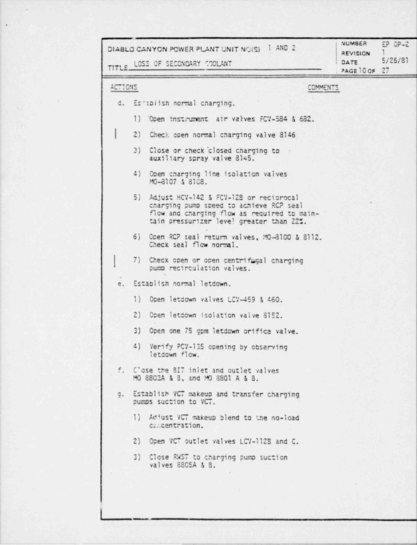
d. Es'uolish nor nal cnarging.
1) 'Open inst.m ment air valves ECV-584 & 682.
| 2) Check open normal enarging valve 8146
3) Close or check " closed charging to -
auxiliary spray valve 8145.
4) Ooen enarging line isolation valvesMO-8107 & 81C8.
5) Adjust HCV-142 & FCV-128 or reciprocal'cnarging pumo speed to achieve RCP seal
flow and enarging ficw as recuired to main-tain pressuri:er level greater than 225.
6) Ocen RCP seal return valves, MO-8100 & 8112.Check seal flow normal.
7) Check open or ocen centrifugal chargingpuma recirculation valves.
'
e. Establish normal' letdown.
1) Open letcown valves LCV-459 & 460.
2) Open letcown isolation valve 8152.
3) Open one 75 gpm ietdown orifica valve.
4) Verify pCV-135 opening by observingletdown ficw.
f. C'ose the BIT inlet and outlet valvesMO 8802A & B, and MO 8801 A & B.
g. Establish VCT makeup and transfer chargingpumos suction to VCT.
1) Adius: VCT makeup blend to tne no-loadcer. centration.
2) Open VCT outlet valves LCV-1123 and C.
3) Close RWST to charging pump suctionvalves 8805A & B.
.
. __ _ . . _ _ _
.
.
-
NUM3ER 5? OP-2DIABLO CANYCN PCWER PLANT UNIT NOIS) 1 AND 2 REVislCN I
cATE 5/25MTITLE LOSS OF SECCNDARY CLCLANT
PACE ll_CF 2,g'-._
ACTIONS COMMENTS
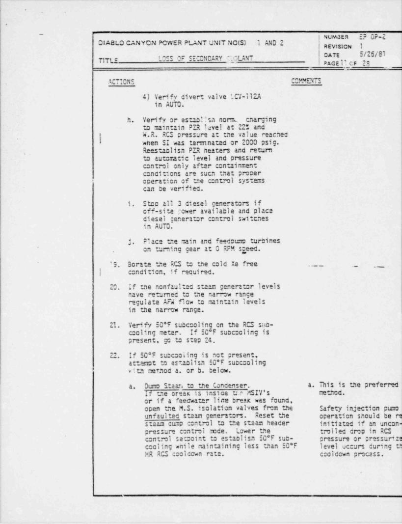
4) Verify divert valve LCV-Il2Ain AtJTO.
h. Verify or esno!!sa nori:L cnargingto maintain FZR level at 22: anc
{W.R. RCS pressure at tne value reachedwnen SI was ter:nnated or 2000 psig.Reesaclisn PIR heaters and return,
to aut:=atic level and pressurecontrol only after containmentc:nditions are sucn :nat proceroceration of the centrol systems-
can be verified.
1. Stco all 3 diesel generators ifoff-site ;cwer available and placediesei generator c:ntrol swittnesin AUTO.
j. Place tne main and fe=cet.mo turbines~ an turning gear at 0 RPM sgeed.' '9. Borate the RCS to the cold Xe free . . _ _ _ ._ ,_
| c:ndition, if recuired.
20. If :ne nonfaulted steam generator levelsnave returned to tne narrow rangeregulate AF4 flow to :.aintain levelsin the narrow range.
21. Verify 50*F subccoling on the RCS sub-c: cling meter. If 50*F subccoling ispresent, go to step 24.
22. If 50*F subccoling is not present,attempt to establish 50*F succ clingvitn merned a. or b. below.
a. Dumo Stear. to the condenser. a. This is the preferred
if tne creax is ins 1ce t:.c MSIV's method. !
or if a feecwater line break was found,open the M.S. isolation valves from the Safety injection pu:raunfaulted steam generators. Reset the operation should be qsteam cump c:ntrol to the steam header initiated if an uncon<pressure control mode. l.ower the trolled drop in RCS |
control setooint to establish 50*F sub- pressure or pressuriz;cooling wnile maintaining less than 50*F level uc urs durino tn~
HR RCS c:olcown rate. c:oldcwn pmcass.
__ _ . _ . __
.
.
NW8ER EP OP-2DIABLO CANYCN PCWhR PLANT UNIT NO(S) 1 AND 2 REvtston 1
ATE 5/25/81TITLE ' nee n'' cer"*m 2 0v can' W.
PAGE 12cF 23
AC ICNS COMMENTS
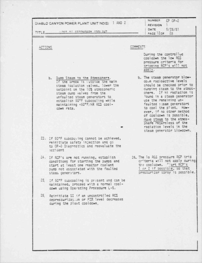
During tne controlledcoolcown the low RCSpressure criteria fortricoino RCP's will notacoly.
b. Dumo Steam to the At=csoner*. b. The steam generator blow-If tne creax is cuts 1ce tne :.ain do n radioactive levelssteam isolation valves, icwer the snould be cnecked prior to
setooint on the 10~. atmos::neric cu.: ping steam to tne atmos-steam cur:o valves imm tne enere. If hi radiation isunfaul ad steam generators to found in a steam generatores colisn 50*F succooling wnile use the remaining un-maintaining <50*F/HR RCS cool- faulted naam generatorsccwn rate. to cool the plint. How-
ever, if no otner methodof cooldown is possible,
dtrao steam to the at:::cs-pnere regardless of theradiation levels in the-
steam generator bicwacwn.
22. If 50*F succousing cannot be achieved,reinitiate safety injection and goto CP-0 Diagnost cs and reevaluate theiccicent
24. If RCP's are not mnning, establish 24.. Tne la RCS pressure RCP tripc::nditions for starting the pu=cs and criteria will not acply during:
start at least one reactor ccolant tre coolcown. 7 art RCP'spumo not asscciated with the faulted 1 cr 2 if cossidie, so tnat
steara gener ttors. pressur1::er spray is possible.
25 If. 50*F succ::aling is pnsent and can bemaintained, pmceed with a normal c::ol-down using Operating Pmcedure L-5.
25 Reinitiate SI if an uncontrolled RCSdepressurizat;an or PIR level decreasesduring the plant c:aldown.
|,
..
I
- - - _ - - - . _ _ _ _ __--
i*
.
.
.
NUMBER EP OP-2~
DIABLO CANYON POWER PLANT UNIT NC(S) 1 AND 2 REvtstCN IDATE 5/25/8l
' Oes or gEc0NOApv Cont:NT ' PAGE 130F 2317TLE -
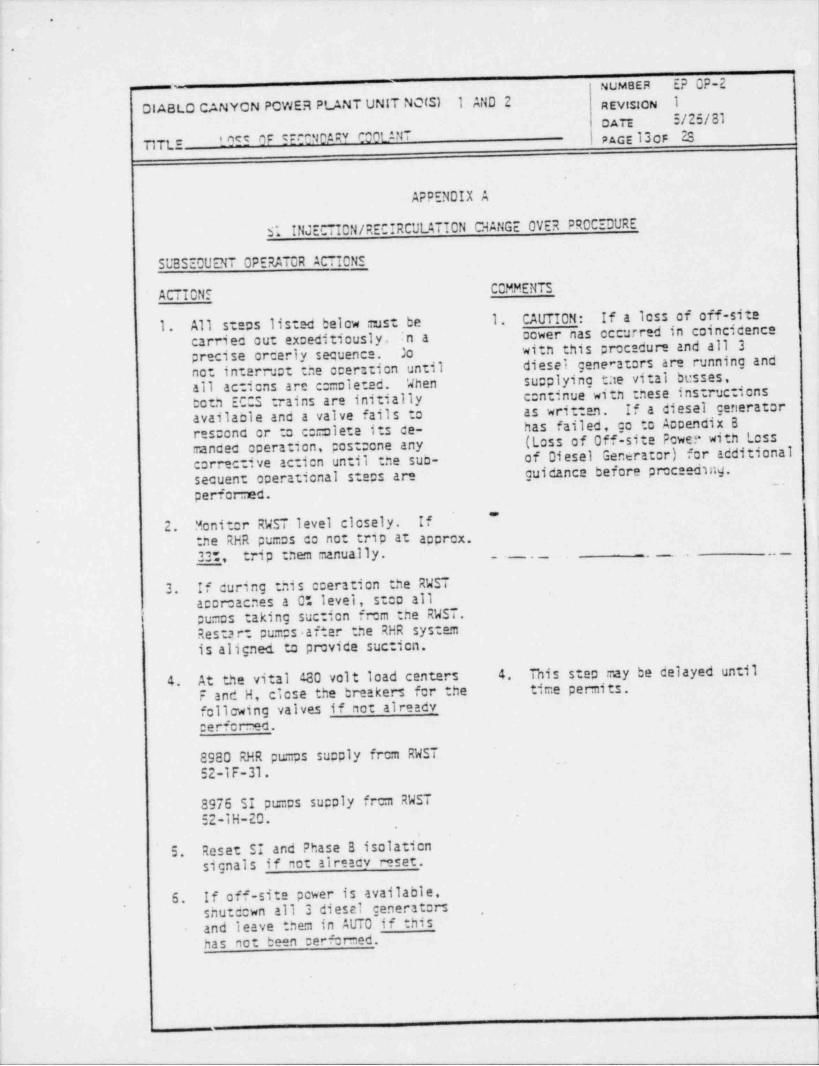
APPENDIX A
S; INJECTION / RECIRCULATION CHANGE OVER PROCEDURE
.SUBSEOUENT OPERATOR ACTIONS
CCMMENTSACTIONF
1. All stecs listed below must be 1. ' CAUTION: If a loss of off-sitecarriec out exceditiously, :n a cower nas cccurred in coincicenceprecise orcerly secuence. Jo witn this precedure and all 3not interruct the cceration until diesei generators are running andall actions are cc=cleted. When supplying tae vital besses,born ECOS trains are initially continue with :nese instruc icnsavailaole and a valve fails to as written. If a diesel generator
has failed, cc to Accendix Bresconc or to ccmolete its ce-(Loss of Off-site Pcwer with Lossmancec operation, postcone anyof Diesel Generator) for additionalcorrective action until the sub-
secuent operational stecs are guidance before preceeding._.
performed."'
2. Monitor RWST level closely. If
- :ne RHR pumps co not trip at aoprcx.33t, trip :nem manually. , ____ __ . _ , _
3. If curing :nis cceration the RWSTaccreacnes a Ot level, stco allpumos taking suction frem the RWST.Restart pumps after the RHR system |is aligned to provide suctica.
-
4. At the vital 180 valt load centers 4. This step may be delayed until -f '.
F and H, ciese the breakers for the time permits.
follcwing valves if not already_cerferrec.
8980 RHR pu.:ps su:: ply frem RWST~
52-l F-31.
8976 SI pumcs supply frem RWST>
52-lH-20.
5. Reset SI and Phase B isolatiensignals if not alreacy reset.
6. If off-site pcwer is available,shutdown all 3 diesel generators ,
and leave them in AUTO if thishas not bean cert:r -ed.
)!
|t

.
.
NUM8sR 5E VEM
DIABLO Ct:NYCN POWET, PLANT UNIT NOIS1 1 AND 2 REvts CN IcATE 3/26/31
I_055 nc (70?t0;.;;V C00f_ ANT gg._
37tc
APPENDIX A (cont)
COP.MENTSAC IONS
7. Close (cut in) tne series contac-ters for tne following valves frcmthe taggle switenes in tne controlroom if not alreadv CUT IN.
8809 A & S RHR pumps injecticn tocold legs.
8974 A & S SI pumps recirculatien..
8982 A & 5 RHR pu=cs suction fromsu=c.
8. With the SI, charging and possibly 8'. Monitor RWST level, trip allpumos taking sucticn from thetne spray pu=cs still taking suc- RWST ucen reacning 0 % level
tion from the RWST and the RHRpu=cs tripced at 33% in the RWST, in the tank. Restart pu=cs
after RHR suction supplied.proceed to transfer RHR suction totne containment su c as follows ir-
steos 9 thru 29. - - - _ ..
9. Check that tne containment recircu-lation st c level indicaters readat least a0". to provide adecuateNPSH to tne RHR pu=cs. . , , ,.
10. Close th'e two RHR heat exchangeroutlet crosstie valves (3716A & B).
11. Close the No. 2 RHR pur:c nor :alsuction valve (87003).
12. Ocen the No. 2 RHR pu=c suctionvalve frem %e containment recircu-lation su=c (S9823).
I3. Open the ce=cenent cooling wateroutlet valve frem No. 2 RHR heatexchanger (FCV-364).
14. Restart No. 2 RHR pt=c and checkflow to the vessel .
15. Close the safety injection pu=c( recirculation valves (8974A & B).|
l
I
i
(I
/!
.
.
. NUM8ER E? OP-2'
OIABLO CANYON PCWE.9 PLANT UNIT NOISI 1 AND 2 | REVisICN I| .
oA'" ~/25/S1-
Tine 1.055 CF SECONDARY COOLANTPAGE15 cF 23
.
APPENDIX A ; cont)
ACTIONS CD.U.MENTS,
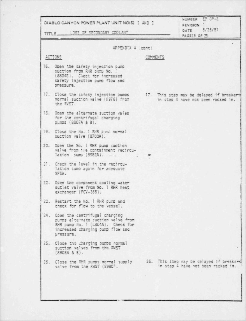
16. Open ?.he safety injection pu :p-suction frem RHR pe=a No. I
(88040). Chcck for increasedsafety injection pu.:o flow andpressure.
17. Close tne safety injection pum::s 17. This step may be delayed if breakertnomal suction valve (8976) frem in steo a nave not been racked in.tne RWIT.
18. Ocen tne alternate suction valesfor tne centrifugal cnargingpc=s (8807A & 3).
19. Close the No.1 F3R p'r.t nomal
suction valve (870CA).
20. Ocen the No. 1 RHR pumo suctionvalve frem tr e containment recircu-lation su== (8982A). ._ _
-
21. Check the level in the recircu-lation sumo again for acecuateNPSH.
.
l22. Open tne component cooling water
outle: valve frem No.1 RHR heatexcnanger (FC7-365). -
22. Restart the No. 1 RHR pumo and ,cneck for flow to the vessel. i
I
'24. Open the centrifugal chargingpumos altan ate suction valve fremRHR pir.o No. 1 (6804A). Check for
,
increased charging pu=o flow and '
pressure.
25. Close tN2 charging ou=os nomalsuction valves frem the RWST '
(8805A & B).
25. Close the FF.R pumos normal supply 25. Tnis step may be delayed if br-skedvalve frem the RWST (8980). in step 4 have not been racked in. i
a
- .
.
NuM;ER *F VF-4..
OIABLO CANYON PCWER PLANT didT NO(S1 1 AND 2 REvtslON 1
LOSS OF'iECONCARY COOLANTTITL- El6 0F. -
APPENDIX A (cont)
ACTI0 tis CCt'MENTS
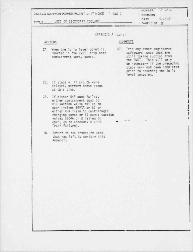
27. When the la lo level point is 27. Trip any other engineeredreached in the RWST, trip both safeguard Sumas that arecontainment spray pumos, still taking suction from -
the RWST. This will only -
be necessary if tne precedingsteps hav3 not been comoletedprior to reacning the lo lo -
level set;oint.
23. If stems 4, 17 and 26 weredelayed, perform these steps
'
at tnis time.
29. If either RHR pumo failed,
eitner c:ntainment suma to |RHR suction valve fatted toopen (valves 8962A or 8) or |eitner RHR Train to centrifugal H
cnarging :cmos or SI pumos suction .!valves 880?A or B failed to ::open, go to Accendix 0 (RHR
~ ~ ~ -'-
Train Failure).
30. Return to tne procecure steptnat was left to perform this
Accendix.
.
t
-.
.
*
NUMBEa E? OP-2CIABLO CANYCN POWER PLANT UNIT NOLSI 1 AND 2 REvis:CN I
I !TITLE 10FF of CEESiCs:V COOLANT
PAGE 170F ES
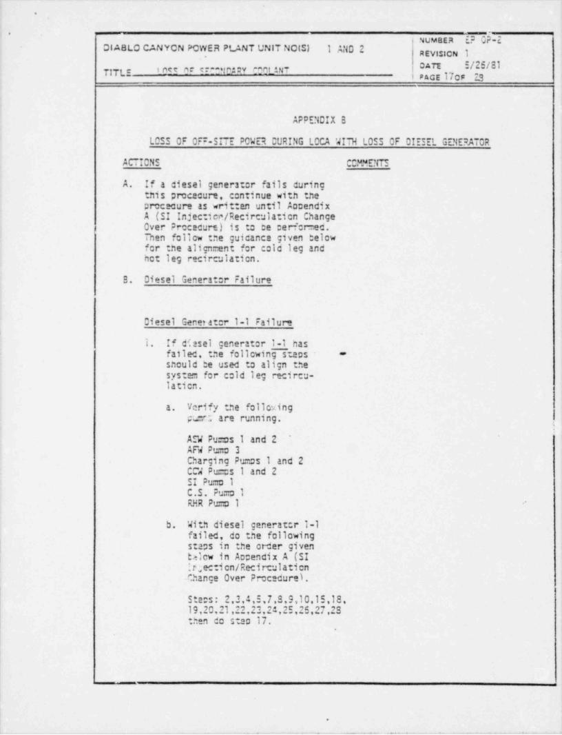
APPENDIX B
LOSS OF OFF-STTE POWER CURING LOCA WITH LOSS OF OIESEL GENERATOR
ACTIONS CCMMENT3
A. If a diesel generster fails duringnis procacure, continue with the
procecure as written until AccendixA (SI Injectien/ Recirculation ChangeOver Procecure) is to ce cerfer=ed.Then follow :ne guicance given belowfor the align =ent for cold leg and ,
het leg recirculation.
B. Diesel Generst:r Failure
Diesel Gener ater 1-1 Failure;
1. If d';asel generator 1-1 hasfailed, the folicwing steps -
should be used to align thesystem for cold leg recircu-latien.
a. Verify the folloxingpL=tt are running.
1
AEW Pu=os 1 and 2 ~AFW Pumo 3Charging Pumas 1 and 2CCW Pu==s I and 2SI Pu=o 1C.S. Pu=o 1RHR Pu=0 1
b. With diesel generatcr 1-1failed, do the following
i staps in the order given| b:-icw in Aapendix A (SI
it;ection/Recirculatien-Change Over Procedure).
Ste:s: 2,3,4,5,7,8,9,10,15,18,19,20,21,22,22,24,25,25,27,23then do step 17.
-,
1
i.
e a t-+ 2 ise t f f
.
NUMBER E? Ch- 2*DIABLO CANYCN POWER PLANT UNIT NO(S) 1 AND 2 REvistoN I
cATE 5/25/81' net nf e f.* * y ry v t*mnt 37T|T( * pace 18 OF 78 ,
--
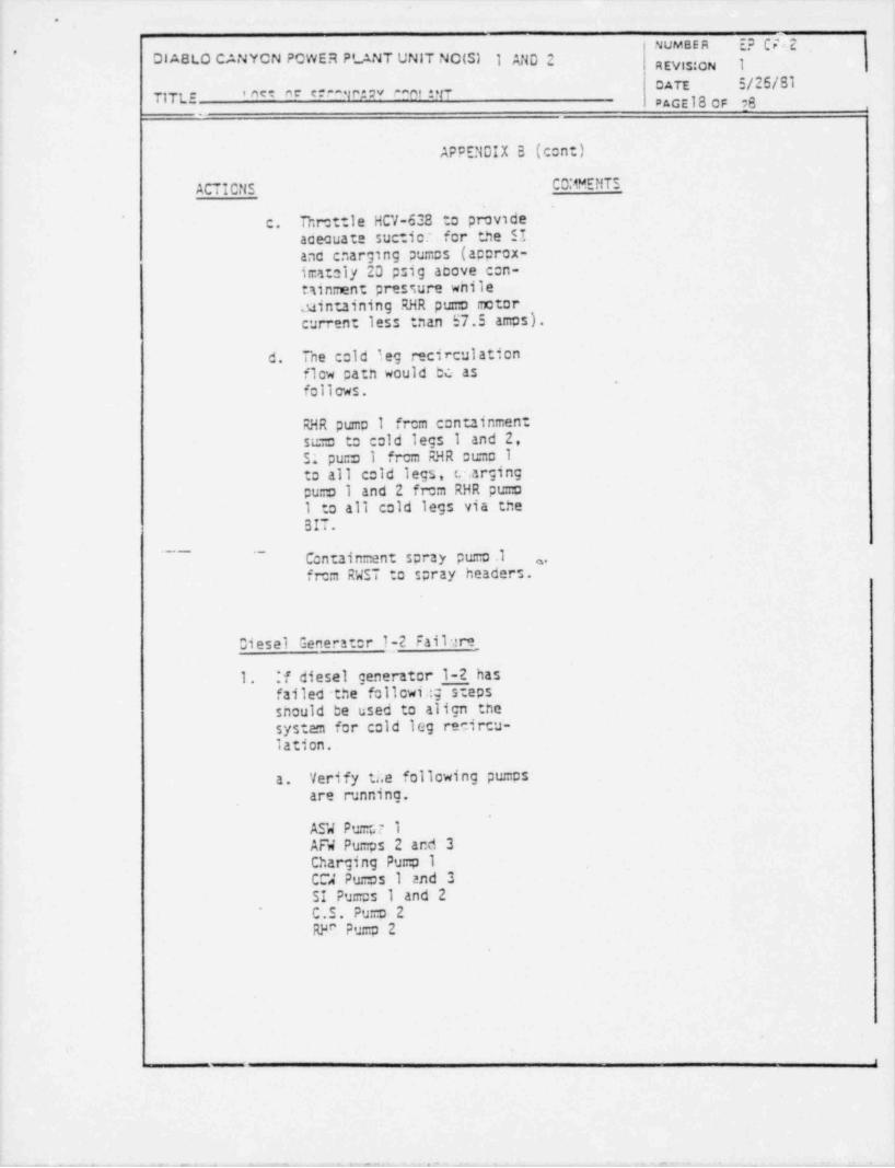
APPENDIX B (cont)
ACTICNS CD:4MENTS
c. Throttle HCV-638 to provideaceouate suctior for the SIano cnarging pumos (approx-imatoly 20 psig acove con-tsinment pressure wnileuinuining RHR pumo motorcurrent less tnan 57.5 amps).
d. Tne cold leg recirculationflow patn would bc asfolicws.
RHR pumo 1 from conuinmentsumo to cold legs 1 and 2,51 puns I frcm RHR oumo 1to all cold legs, c.:.argingpumo 1 and 2 from RHR pu=o1 to all cold legs via the
BIT.- - Centainment spray pu=o .1 ,
, , ,
from RWST to spray headers.
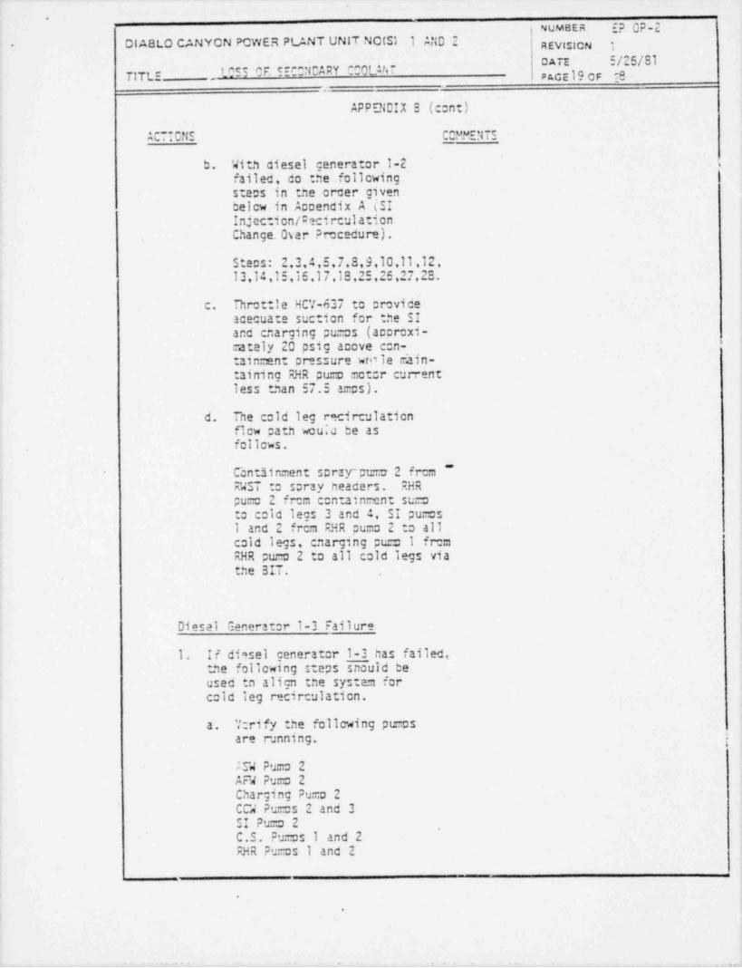
Diesel Generator 1-2 Fail ara
1. :f diesel generator I-2 hasfailed the followi :g stepssnould be used to align thesystem for cold leg recircu-lation.
a. Verify ti.e following pumpsare running.
ASW Pu:r.,7 1AF4 Pur:ps 2 and 3Charging Pump 1CCW Puras 1 and 3SI Pumas 1 and 2
'
C.S. Pumo 2RF" Pu=p 2
f
, .r . -,: , , - e c. i - , -- , - - - -
.
NUMBER E? OP-2DIABLO CANYCN PCWER PLAMT UNIT NO(Sl 1 AND 2 REVislCN i.
DATE 5/25/81TrrLE , LOSS OF SECCMCARY CCOLU,7 pace 19 OF E8
APPENDIX S (cont)
ACTICNS CCMMENTS
b. With ciesel generator 1-2_ \failed, do tne followingsteps in :ne orcer given
below in Accendix A (SIInjection /pecirculationChange. Oser Procecure).
Steos: 2,3,4,5,7,3,9,10,11,12,13,14,15,15,17,18,25,25,27,23.
c. Throttle HCV-637 to proviceacequate suction for the SIand cnarging pu=os (accroxi-mately 20 psig acove con-tain=ent pr-ssure wro le dain-taining RHR pumo motor currentless than 57.5 amps).
d. The cold leg recirculationflow cath wou;c be as
follows.
Contiinment scraran=a 2 frc= ~RWST to spray heacers. RHRpu=c 2 from contain=cnt sumoto cold legs 3 and 4, SI pu=cs1 and 2 frcm RHR pumo 2 to all
'cold legs, enarging pu=c 1 fremRHR pumo 2 to all cold legs viathe BII.
Diesal Generator 1-3 Failure
1. If di-sel generator 1-3 has failed,the following steps snould beused tn align tne system forcold leg recirculation.
a. "crify the following pumpsare running. ;
ASW Pu=c 2AFW Pumo 2Charging Pumo 2CCW Pu=cs 2 and 3SI Pums 2 ,
C.S. Pumas 1 and 2RHR Pumos I and 2
.
D
= .+e.

_ - _ _ _ - _ _ _ _ _
.
.
. NUMBER EP OP-2DIABLO CANYCN PCWER PLANT UNIT NO(S) 1 AND '? R EVISION I
[/26/8IUA"TIT 1.E LOSS OF SECCNCARY COOLANT
Pace 20 cF 6
APPENDIX 3 (cont)
ACTIONS COMMENTS
b. With tne diesel generattr1-3 failed, co the followingsteps in :ne order g1ven
below in Accandix A (SIInjection / Recirculation ChangeOver Procecure)..
t: Steps: 2,3,4,5,7,8,9,10,.11,12,13,
14,15,16,17,18,19,20,21,22,23,24,27,23.
c. Tnrottle HCV-638 and 537 toprovide acecuate suction for theSI anc cnarging pu:::o (approxi-mtely 20 psig aoove containmentpressure wnile maintaining RHRour o motor current less than57.5 amos).
-
- - --f- The cold leg recirculatien - -- -
flow path would be as follows.
Centainment scray pumos 1 and 2from RWST to spray headers.RHR pumo No. 2 from gentainmentsu=p to cold legs 3 and a andto SI pu:::p No. 2.
SI puma No. 2 frem RHR No. 2 tocold legs 3 and A.
RHR puro No.1 from containcentsumo to cold leg 1 and 2 andto No. 2 centrifugal chargingpu :o.
CentrifJgal charging pumo No. 2frem RHR Pu.:o No. 2 to all cold
- legs via the BIT.

.
.
.. M BER E? OP-2DI ABLO CANYON PCWER PL/.NT UNIT NOIS) 1 AND 2 REVistoN 1
UA" I/20/8ILOSS OF SECONDARY CCOLANT' 1TL:- PAGE 210F 2S
APPENDIX C
AUXILIARY r::9 PUMP SUC~ ION SUPDLY ORCM FIRE WATER TANK
The coerator has 20 minutes to perfonn this aceration after the lo lo levelalann en tne concensate storage tank anc before tne AP4 pumas lose suction.This provices sufficient time; nowever,tne coerator must not delay and mustcarry out the valve line up in orcer as written.
.
; If the AFW cumos are being sucolied frem the raw water reservoir and a seismici event occurs with resultant loss of AF4 suction and auxiliary feecwater flow to
tne steam generators, the steam generators will boil cry in acout 30 minutes.Uncer nese concitions, it is especially imer: ant to excedite this procedureanc raestaclisn AF4 flow to the steam generators prior to one reac:cr losingits he.it sink.
ACTIONS COMMENTSI
Using the attached drawing, proceed tosu: ply the AF4 pu:=s suction frem thefire water tank. -
1. Cicse or verify closed MU-0-234 'l. Closing these vahes preventsand MU-0-286, losing fire water out a possible
break in :ne reservoir supplyline.
2 '~ Close' cr check closed.MU-t 298..
,
3. Close or check closed MU-0-325.
4 Cicse or check closed MU-0-427.
5. Open FP-0-306 and FP-0-307.
6. Notify the centrol recm that the, suction for the AF4 pumps is nowavailable frcm the fire water tank.
7. Frcm the c:ntrol recm open FCV-436and 437.
~
Proceed to tne auxiliary feecwater8.pumps and vent the puro casings ifrequired- to remve air.
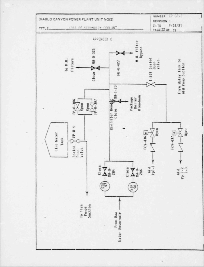
'
.
.
gg y o?*;
o og^j@ ya$uC2y, - o g~ ,
g< *-
7g R' 5 A"j a a" 31y >- j 5di_ ;g " 2
Il
;o xnz-ret
l s5 is
Fa23 j Vu y p
- .y0 U. D d. s -
r U 7 H e e oU. te H 2 l nv nH t 4 ael k o
- cpayAl " 0 SOV nio i atT F - Tce i 7l us H 9 rSo 2 el - t pC 1 an i
1 Ul ul
P9 e2 rD
- if1 FA-u n
erwti
6 - 7 gr1 0
" geo3 n J <
p ] al d
0Xd eM0 l e P U
kl w- e - a coo
.
,p p e aD1
P.|O- O - l
sF - F ro
I
eltCaH
_ -w4 a- ' t- H n j :
g <'0 e e. r - u p p
e P O Ot F 6 7 [
a k 3 3l n 4 4l
a - - )
[.
e T V V
/r d C Ce e F Fi
F l nv [ [aelcnaSOv
-
< <-e )
sM04 oMhl- e - . 23i
o s 06 fl - -li
l - 8 8 Ap f1lC U2 ll 2 p A
H
-C pt
P
S,
' -]
> ,
e nrso
.i piF mt
uc ar .
oPu aiT S Ho
v _mroe ._
_ rs -
_ Fe ~_
R
ret -
a.ll .
_
__-.
_
- .
_

.
<
~
1 NUMBER :D OP 2-DIABLO CANYON POWER PLANT UNIT NO(S) 1 AND 2 yggy,ggy
OATE *i26/81TITLS '"FS O' 5 ~0NOARY T OLAN7 pacg23 op h-
_
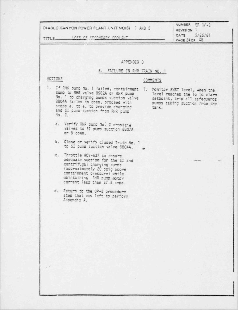
APPENDIX D
RHR TRAIN /CCMPONENT FAILUREA. FAILURE IN Rha TRAIN NO. 2
ACTIONS COMMENTS
1. If RHR pu..:o No. 2 failed, 1. Monitor RWST level, unen
containment sumo to RHR valve the level reaches the lo 1089823 or RHR puro No. 2 to SI alarm set::oint, trip all
suction valve 88048 failed to safeguarcs ou=os taking suctionopen proceed witn steos a. to from the tank.e. to provide cnarging and SIpumo suction from RHR pumoNo. 1.
a. Verify RHR pu=D No. Icrosstie valves to SIpu=D suction 8807A or3 open.
,
~ b. Close or verify closed~
Train No. 2 to SI pumasuction valve 88048.
c. Tnrot:le HCV-638 to ensureacecuate suction for the SIanc centrifuctI cnargingpu=os (acproximately 20psig cbove . containment .
pressure) wnile maintainingRMR puma motor current iessthan 57.5 a.ms.
d. Rerum to the OP-2 procedurestem that was left to performAcpendix A.
,
l
.
|
|
|
|
|
|
|
.
.
!
9 ,
O
-
NUMBER EP C/.2DI ABLO CANYON POWER PLANT UNIT NOIS) 1 AND 2 REVislCN 1
oATE 3/26/81TITLE ' "IE OFl30W" '*00' ANI PAGE 240F 28
APPENDIX 0
3. FAILURE IN RHR TRAIN NO.1
ACTIONS COMMENTSi
1. If RHR puma No.1 failed, containment 1. Monitor RWST level, wnen thesu=a to RHR valve 8982A cr RHR pu=o level reaches the lo lo alarmNo.1 to charging ou=os suction valve setooint, trio all safeguardsESO4A failed to coen, proceed with pu=os taking suction frem thesteos a. to e. to provice cnarging tan k,and SI pu=c suction frem RHR pu=cNo. 2.
a. Verify RHR pe=a No.' 2 crosstlevalves to SI pu. o suction 8807Aor 6 coen.
b. Close or verify closed Tetin No. Ito SI pu=o sucticn valve 8804A.
.,
c. . Throttle HCV-637 to ensureadecuate suction for the SI and - - -
centrifugal cnarging pur:as(accroximately 20 psig acovecontainment pressure) wnilemaintaining RHR pt=:0 motorcurrent 1ess tnan 57.5 a=cs.
d. Return to the CP-2 precedurestep that was left to performAppendix A.
1 e
_

-n ,
i NUMBER E? OP-2,
DIABLO CAMYCW PCWER PLANT UNIT MO(S) I anc 2 | REV!sION I
LCSS OF SECCNCARY CCCLANT DATE 3/26/8l7;7g, PAGE 230F 28 |
APCENDIX E
1. If the vitai busses lose voltage criar to resetting me safety injectionsignal, the vital cusses will aut:matically loac :ne vital ecui=entgiver. below. Verify tne ecuic ent has been loaced by ocserving breakerlignts on =e c:ntrol boarc.
2. If the vital busses lose voltage after tne safety injection signal hasbeen reset, loac or verify loacec :ne ecuignent given below onto thevital busses manually. Allow accroximately 4 seconcs between loadingof ear.n piece of ecuits:ent onto a given vital bus. Load or verifythat the CFCU are running in low sceed.
VITAL 505 VITAL SUS VITAL SUSF G H
0/G l-3 D/G l-2 0/G l-1MCC 1-F MCC 1-G MCC 1-H
CC Pp 1-1 CC Pp 1-2 SI Pp l-2SI Pp l-1
| CFCU 1-2 RHR Pp l-1 RHR Pp l-2- CFCU 1-1 CFCU 1-3 CFCU 1 4
~
C Q Pp 1-1 CFCU 1-5 CQ % l-3
ASW Pp 1-1 CCW Pp 1-2 AN Pp 1-2
i AFW Pp l-1 ASW Pp 1-2i
!
3. Load the Contain=ent Spray Pumas only if tney wen running rior totne blackout.- -
'
| VITAL SUS_
VITAL SUL
|G H
i| I Cont Spray Pp 1-1 Cont Scray Pp 1-2
.
.
y .- %

-
.
o -. .
NUMBER Ep Op.2 |DI ABLO CANYCN PCWER Pt. ANT UNIT NCISI I and 2 R Evts!ON 1
DAR 2MILOSS OF SECCNCARY CCOLANT1TL:- pacs 45cp 8-
.
APPENDIX EEMERGENCY PROCECURE NOTIFICATION
INSTRUCTIONS
1. When nis eiergency procecure has been activated and upon direction fremthe Shift Forman proceec as follows.
t. Designate this event an Unusual Event. Notify Personnel as ::erEmergency Procedure G-2 (Estaolishment of On-Site Emergency Organization)
- b. If a rajor steam line break is accomoanied with primary to secondaryleakage >10 g;:m designate this event as an Alert. Notify tnoseagencies given in Emargency Procecure G-3 (Notification of Off-SiteOrganization) .
c. If the primary to secondary leakage progresses to >50 gpm with fueldamage evicent, designate this event as a Site Area Emergency.
e. Within one hour notify tne NRC Ooerations Center using the red phonein the Control Roem. Gather sufficient infor .ation frem all sourcesprior to calling so mat tne ::none call is meaninciul . Notify the ..
NRC that your call is ;:ursuant to 10 CFR Part 50.72. , (Notification of~
Significant Events) .
.
t
i
I3
.

--.-..
a_=
NUMBER d E-dDIABLO CANYCN POWER PLANT UNIT NO(S) I AND 2 REVISICN I
DATE 5/26/83T1',''U, inee ne ere~_s.n_.s v can_t_ n47
..PAGE27_ce ?S
____ -_
. . . . . .
2 3 .. ._. . . _ _ . .
a 00-- - -- 1 ' Saturdon qurve with no.-- -- V --
r . i n s trume._n.t..e_r_ro rs . --
DJ.
, . . =_..=-_:____:. . _.: .:::: ,. - .k: 1 - - .
. - .
= . . - _ _ _ _ _ . -.
. ..
._..i . .gii.E.ii. = ~ ~ i .; ' !. _
.l' =. ;.: t - . |
~ ~ ~ ~ -_. ,
*
.
'.2 : . Saturation curve with censervative.. f. |[t .
.g_-...
- . :-_- ! 9-- .J..
_ir..w.snu=ent errors , for use witn. ..
:. .|, . .
.=d-dCT pressr.tre z_M.f~.1R!, R. CS .Tnc.. . ~J.53-#).- '. j:t .. ...:.. .. ~ L. .'. . ~|-
200C .: | | P--f ' !. . .
't- ',. .
- -
.. . . _ ."-. f.'.:i: .d- .-h =- n.. a.k.:1 2:. : . ::.m.- _ ' :: : = - ' ~ ~-
,;[ [i :-- . ' .: --
|a=._...=--- - -
_.. .* _-
,,
. _- D.:.. .; =. . . i_.=. .: .- |. _Q. . . .r_..-- -
.. C- ..! _d_ _;s._:=:!=_: : .: ;.
. . - - - - - - - ,_.
W. . . . .::: . - - - ~ ~ . . . .,
d .!:.=: _j..:C. T .: ,]'
_..-. E-
;
: i n 1 -m=_u;;; .m --
1... i il' ? - %
.
.J
-
--._. ] i i
j i
.4 ;. L_ .-i- ::@_ __ _ g |, . .:._.__.. . . . _ .. ._.- ::: .:
_a
-
_,: _.. . . . . , , . 'i
_..t"__- . _ .i , , _ . _ _
i l . C.2. . .- . ' __: _; . - i_ , .i- 'g __
.. - -. . . . ..s. . . ... . . . .-
. ,. :
_. f ..__.._=-~=:.-:.- .,- .. ...:
* ~'
_.n.i.~J~__=._'~.'_.-- .= . ':=--- =ii. =. ..i=.: '. . : .- -i .'
. . . . . - .f . . . . =- '===. . d.;_ . . i. 5 i.- - =. -. . .
' -~ sr_ --- : .g :. : . - - . i _=i .:. : -- - R I _:. gr .: r: . =.:.:t _.
. - - . s .. -
:RC5 - "==" = '==-"r-- :I == f ''---- ~ - - - -
-
Pressure _ _.E:_ . ;. -g._.._... _ _
=_ - _: _ .;E.. . -_
.-
p$ $ g )',
. , - - -- -
._...__._;..... __ . . . _ . .,
. ._. __ .; :..
,
.
._-
-. . _ = = a ..:...--.--
_ . .
AbCZEIABLE. .
i- . AREA.. 7 CE. TABLE
. . ._ _
A RE.s~
"
._. = _ . . .._ ,. _ . _ _ _ _ _.. .
_.__ ,
-: . y-__
- --. . e _.
- ..__ e
. . - . .10CC - - - -
_.. . . . _ . .--- - . .
' -
%...
.._ ; .. _ _ _ _ ._
s.'_. . _ . - . . .
. ~ =..u. r -. --"*
r .- - - - -
-._._ _._
t . .-;_ .u . 4 -t' --; ~-
. = . _ _ _ _ ..
_ __.._ _,. .;.. .
... _ . _ _ . _
... m. ,
.- . _ . , . - .. . . . . . . . .
. . .-
u., . ..
-; -;. n. - 2:2.r_. . .
..i .. .u . : =.:: . . . - . - - " _ . . . _ _ __ y __. --- . . .
-_
__
l' - - := . - '~2; -@_ 3_C5' SATUMIION*
,
.J - _= - _ . . . - i?.~ i . . 3.- .. _-i CURV E - - -i: ..- -...u.
g, _
! =_ = - 2.== .._.;-.. ~_=....i. -~ 4/. --
b. . .-- . .
3,.
-
s . ; : . ._.- .
t ^ 2:. .V: _; -- __ - - | . . ,| -.
*- -; - ._ __. _ ; . _ _ . . - - '...-l :. :. - - - ----- ; J . .
- - -
- . . . . , , . . - -.u . i.._ ; -. 4.- |
-
::0C-'
.
. . .
;
.c_. i ":. 4? ";- i ,4
__ . _ _ . _ . . _ . - - . . . _ , . _ _ _
.~.. ' J100 . .- - -
-
t- -.
.-
"-
.3 _ _ _ . .__ ._. ._ .
- g-'
00 - "
.b~ _ . .. . . . . _ . _
. =..-_:. . r n:. _.
: ; - W. RCS Tercerature PF) __-_ __I'
400,, . . . . . .
0 100 200 300 '400 500 600 700,
.
.h ph 6
-
_ _ _ _ _ _ _ _ _ _ . _ . _ _ . - - _ _ _ _ _ _ _ . _ _ _ _ m____ _ _ _ _ _ . _ _
-
0
NUMBER :D QP-2DI ABLO CANYCN PCWER PLANT UNIT NOIS) I AND 2
~
REVtsICN I
LOSS OF SECONDARY COOLANT oAn S/26/81.UL- Pacz 23 oF 2S'
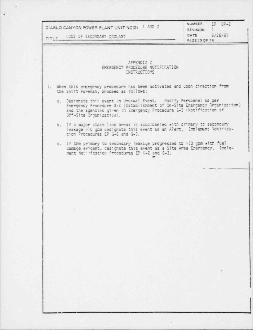
APPENDIX ZEMERGENCY PROCEOURE NOTIFICATICN
INSTRUCTIONS
1. When :nis emergency procedure has been activated and ucen cirection fromthe Shift Foreman, proceed as follows:
a. Designate this event an Unusual Event. Notify Personnel as perErergency Precedure G-2 (Estaolishment of On-Site Emergency Organization)and tne agencies given in Emergency Procacure G-3 (Notification ofOff-Site Organ 1:atica).
b. If a major steam line break is ac: maanied with crimary to seconcaryleakage >10 gpm designate this event as an Alert. Imolement Notifica-tien Prececures E? G-2 and G-3.
c. If the primary to sec:ndary leaktge progresses to 250 gpm with fueldarage evicent, designate this esent as a Site Area Emergency. Imole-ment Not'1icaricn Prececures E? G-2 and G-3.
-__ _
e
6
1 -
.