Embed Size (px)
Citation preview
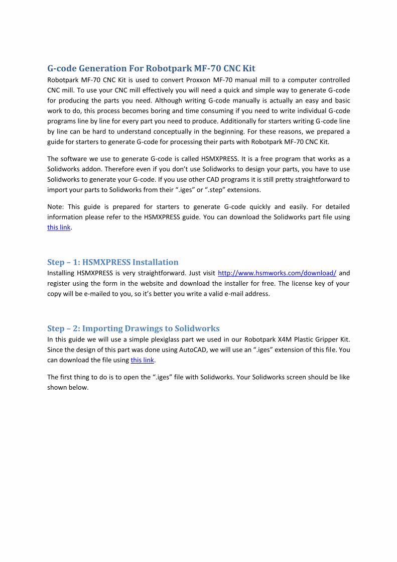
G-code Generation For Robotpark MF-70 CNC Kit Robotpark MF-70 CNC Kit is used to convert Proxxon MF-70 manual mill to a computer controlled
CNC mill. To use your CNC mill effectively you will need a quick and simple way to generate G-code
for producing the parts you need. Although writing G-code manually is actually an easy and basic
work to do, this process becomes boring and time consuming if you need to write individual G-code
programs line by line for every part you need to produce. Additionally for starters writing G-code line
by line can be hard to understand conceptually in the beginning. For these reasons, we prepared a
guide for starters to generate G-code for processing their parts with Robotpark MF-70 CNC Kit.
The software we use to generate G-code is called HSMXPRESS. It is a free program that works as a
Solidworks addon. Therefore even if you don’t use Solidworks to design your parts, you have to use
Solidworks to generate your G-code. If you use other CAD programs it is still pretty straightforward to
import your parts to Solidworks from their “.iges” or “.step” extensions.
Note: This guide is prepared for starters to generate G-code quickly and easily. For detailed
information please refer to the HSMXPRESS guide. You can download the Solidworks part file using
this link.
Step – 1: HSMXPRESS Installation Installing HSMXPRESS is very straightforward. Just visit http://www.hsmworks.com/download/ and
register using the form in the website and download the installer for free. The license key of your
copy will be e-mailed to you, so it’s better you write a valid e-mail address.
Step – 2: Importing Drawings to Solidworks In this guide we will use a simple plexiglass part we used in our Robotpark X4M Plastic Gripper Kit.
Since the design of this part was done using AutoCAD, we will use an “.iges” extension of this file. You
can download the file using this link.
The first thing to do is to open the “.iges” file with Solidworks. Your Solidworks screen should be like
shown below.
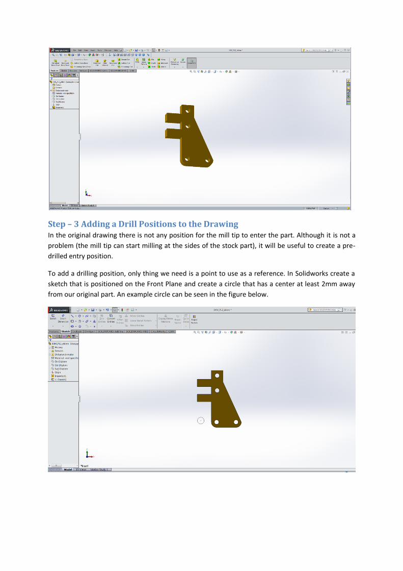
Step – 3 Adding a Drill Positions to the Drawing In the original drawing there is not any position for the mill tip to enter the part. Although it is not a
problem (the mill tip can start milling at the sides of the stock part), it will be useful to create a pre-
drilled entry position.
To add a drilling position, only thing we need is a point to use as a reference. In Solidworks create a
sketch that is positioned on the Front Plane and create a circle that has a center at least 2mm away
from our original part. An example circle can be seen in the figure below.
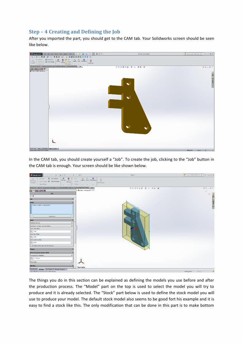
Step – 4 Creating and Defining the Job After you imported the part, you should get to the CAM tab. Your Solidworks screen should be seen
like below.
In the CAM tab, you should create yourself a “Job”. To create the job, clicking to the “Job” button in
the CAM tab is enough. Your screen should be like shown below.
The things you do in this section can be explained as defining the models you use before and after
the production process. The “Model” part on the top is used to select the model you will try to
produce and it is already selected. The “Stock” part below is used to define the stock model you will
use to produce your model. The default stock model also seems to be good fort his example and it is
easy to find a stock like this. The only modification that can be done in this part is to make bottom
offset 0mm because we want our part to have the desired thickness after the process and we
certainly use a plexiglass stock that has the thickness of our model. You can cut a plate from a bigger
plate to match the stock model or if you have an excess part from your other processes, you can
create a similar stock model to use in HSMWORKS.
In “WCS” part, we can define the coordinate system we will use for G-code generation. This part is
very important because the center position of the workspace and the working plane is defined using
this part and a wrong selection in this part will possibly cause our CNC to be damaged while working.
In this example by default the Front Plane and Sketch origin are selected for reference which is
suitable for our work. For different processes you may have to change the default selections.
Selecting the working plane and the origin manually is also possible.
You can click on the green tick sign and continue.
Step – 5: Creating and Defining the Processes After defining the starting stock and coordinate system, we basically defined our job. The next thing
to do is to create and define the processes like drilling and milling which create our desired part.
When you think about our starting stock part and the model we want to create, drilling first and then
milling the sides of the model starting from the drilled holes seems to be the most logical approach.
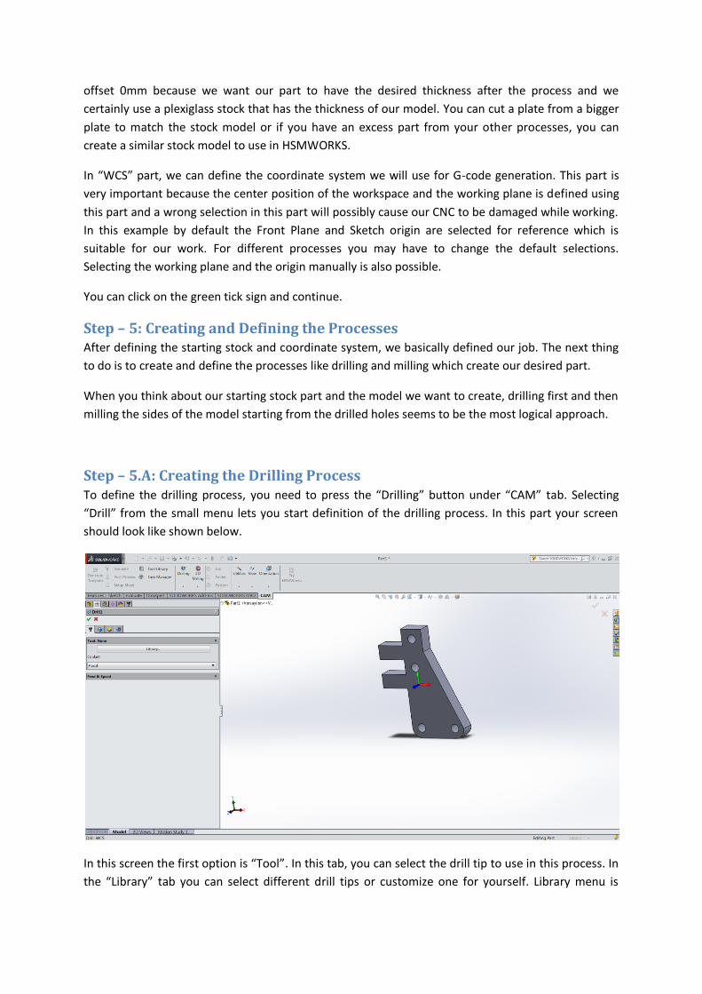
Step – 5.A: Creating the Drilling Process To define the drilling process, you need to press the “Drilling” button under “CAM” tab. Selecting
“Drill” from the small menu lets you start definition of the drilling process. In this part your screen
should look like shown below.
In this screen the first option is “Tool”. In this tab, you can select the drill tip to use in this process. In
the “Library” tab you can select different drill tips or customize one for yourself. Library menu is
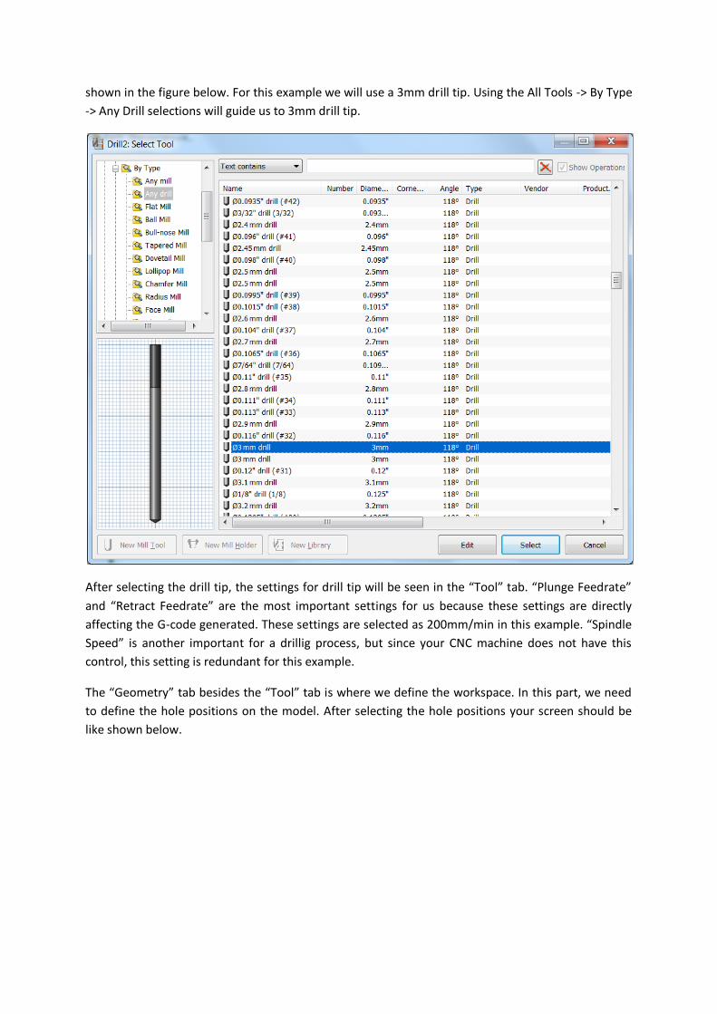
shown in the figure below. For this example we will use a 3mm drill tip. Using the All Tools -> By Type
-> Any Drill selections will guide us to 3mm drill tip.
After selecting the drill tip, the settings for drill tip will be seen in the “Tool” tab. “Plunge Feedrate”
and “Retract Feedrate” are the most important settings for us because these settings are directly
affecting the G-code generated. These settings are selected as 200mm/min in this example. “Spindle
Speed” is another important for a drillig process, but since your CNC machine does not have this
control, this setting is redundant for this example.
The “Geometry” tab besides the “Tool” tab is where we define the workspace. In this part, we need
to define the hole positions on the model. After selecting the hole positions your screen should be
like shown below.
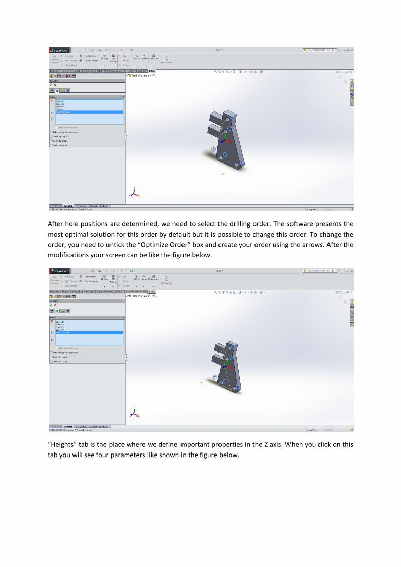
After hole positions are determined, we need to select the drilling order. The software presents the
most optimal solution for this order by default but it is possible to change this order. To change the
order, you need to untick the “Optimize Order” box and create your order using the arrows. After the
modifications your screen can be like the figure below.
“Heights” tab is the place where we define important properties in the Z axis. When you click on this
tab you will see four parameters like shown in the figure below.
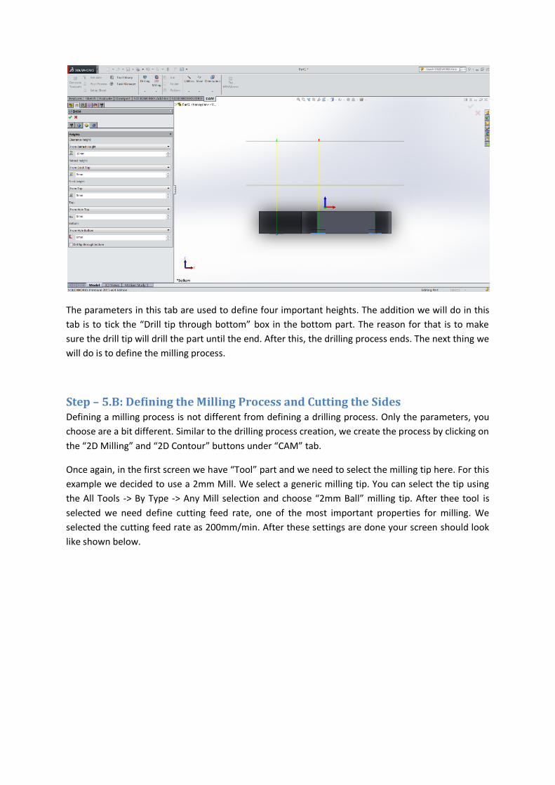
The parameters in this tab are used to define four important heights. The addition we will do in this
tab is to tick the “Drill tip through bottom” box in the bottom part. The reason for that is to make
sure the drill tip will drill the part until the end. After this, the drilling process ends. The next thing we
will do is to define the milling process.
Step – 5.B: Defining the Milling Process and Cutting the Sides Defining a milling process is not different from defining a drilling process. Only the parameters, you
choose are a bit different. Similar to the drilling process creation, we create the process by clicking on
the “2D Milling” and “2D Contour” buttons under “CAM” tab.
Once again, in the first screen we have “Tool” part and we need to select the milling tip here. For this
example we decided to use a 2mm Mill. We select a generic milling tip. You can select the tip using
the All Tools -> By Type -> Any Mill selection and choose “2mm Ball” milling tip. After thee tool is
selected we need define cutting feed rate, one of the most important properties for milling. We
selected the cutting feed rate as 200mm/min. After these settings are done your screen should look
like shown below.
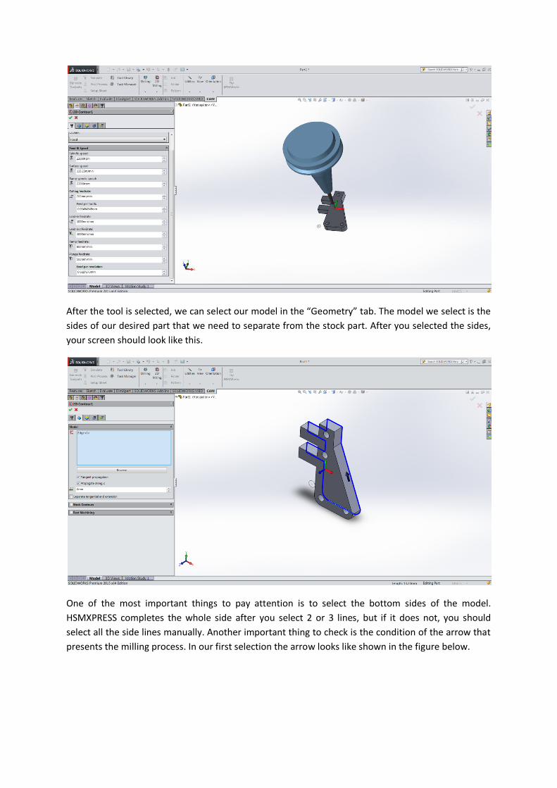
After the tool is selected, we can select our model in the “Geometry” tab. The model we select is the
sides of our desired part that we need to separate from the stock part. After you selected the sides,
your screen should look like this.
One of the most important things to pay attention is to select the bottom sides of the model.
HSMXPRESS completes the whole side after you select 2 or 3 lines, but if it does not, you should
select all the side lines manually. Another important thing to check is the condition of the arrow that
presents the milling process. In our first selection the arrow looks like shown in the figure below.
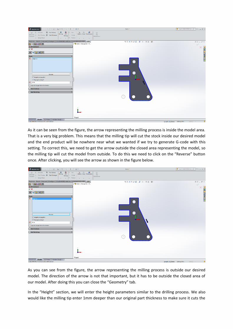
As it can be seen from the figure, the arrow representing the milling process is inside the model area.
That is a very big problem. This means that the milling tip will cut the stock inside our desired model
and the end product will be nowhere near what we wanted if we try to generate G-code with this
setting. To correct this, we need to get the arrow outside the closed area representing the model, so
the milling tip will cut the model from outside. To do this we need to click on the “Reverse” button
once. After clicking, you will see the arrow as shown in the figure below.
As you can see from the figure, the arrow representing the milling process is outside our desired
model. The direction of the arrow is not that important, but it has to be outside the closed area of
our model. After doing this you can close the “Geometry” tab.
In the “Height” section, we will enter the height parameters similar to the drilling process. We also
would like the milling tip enter 1mm deeper than our original part thickness to make sure it cuts the
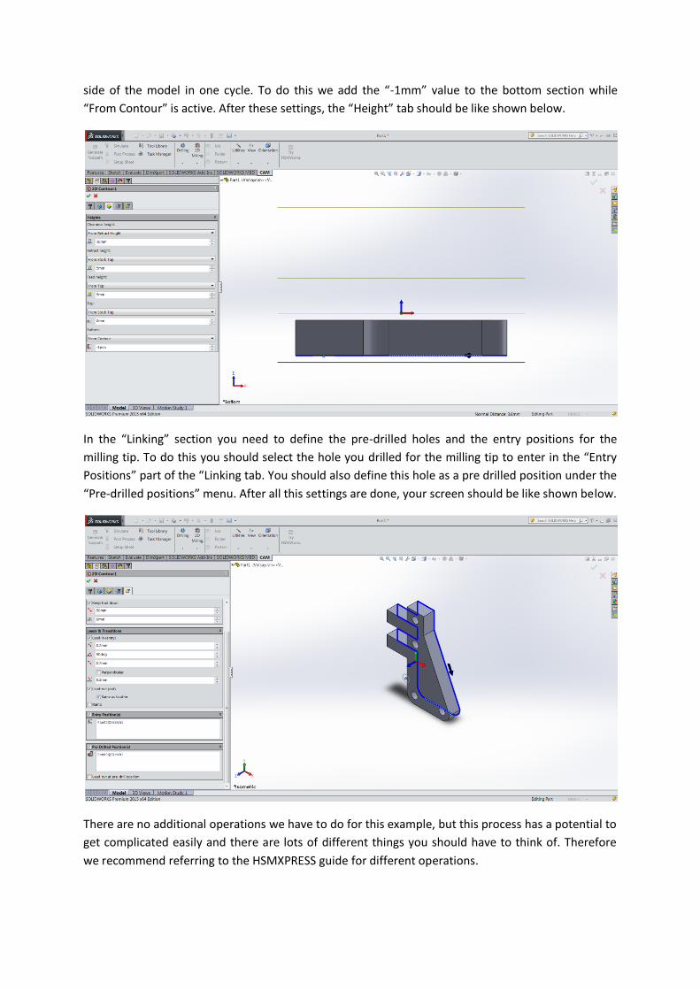
side of the model in one cycle. To do this we add the “-1mm” value to the bottom section while
“From Contour” is active. After these settings, the “Height” tab should be like shown below.
In the “Linking” section you need to define the pre-drilled holes and the entry positions for the
milling tip. To do this you should select the hole you drilled for the milling tip to enter in the “Entry
Positions” part of the “Linking tab. You should also define this hole as a pre drilled position under the
“Pre-drilled positions” menu. After all this settings are done, your screen should be like shown below.
There are no additional operations we have to do for this example, but this process has a potential to
get complicated easily and there are lots of different things you should have to think of. Therefore
we recommend referring to the HSMXPRESS guide for different operations.
To accept the settings you have done, click on the green tick and complete the milling process. After
you complete this process the toolpath is automatically calculated. Just to be sure right click on the
job you created first and select “Generate Toolpath”. The next step will be about simulating the
toolpath we created here.
Step – 6: Simulation The operations we have done up till now seems basic, but even the smallest mistake done in this
operations may cause failure in producing our part, but this may be the smallest of your problems. If
you use a faulty G-code you may destroy your working part, harm your CNC machine or the worst
you can injure yourself. For those reasons taking precaution is the best solution. One of the best
solutions to detect faults in your G-code is to simulate your code and check if it is working as you
wanted.
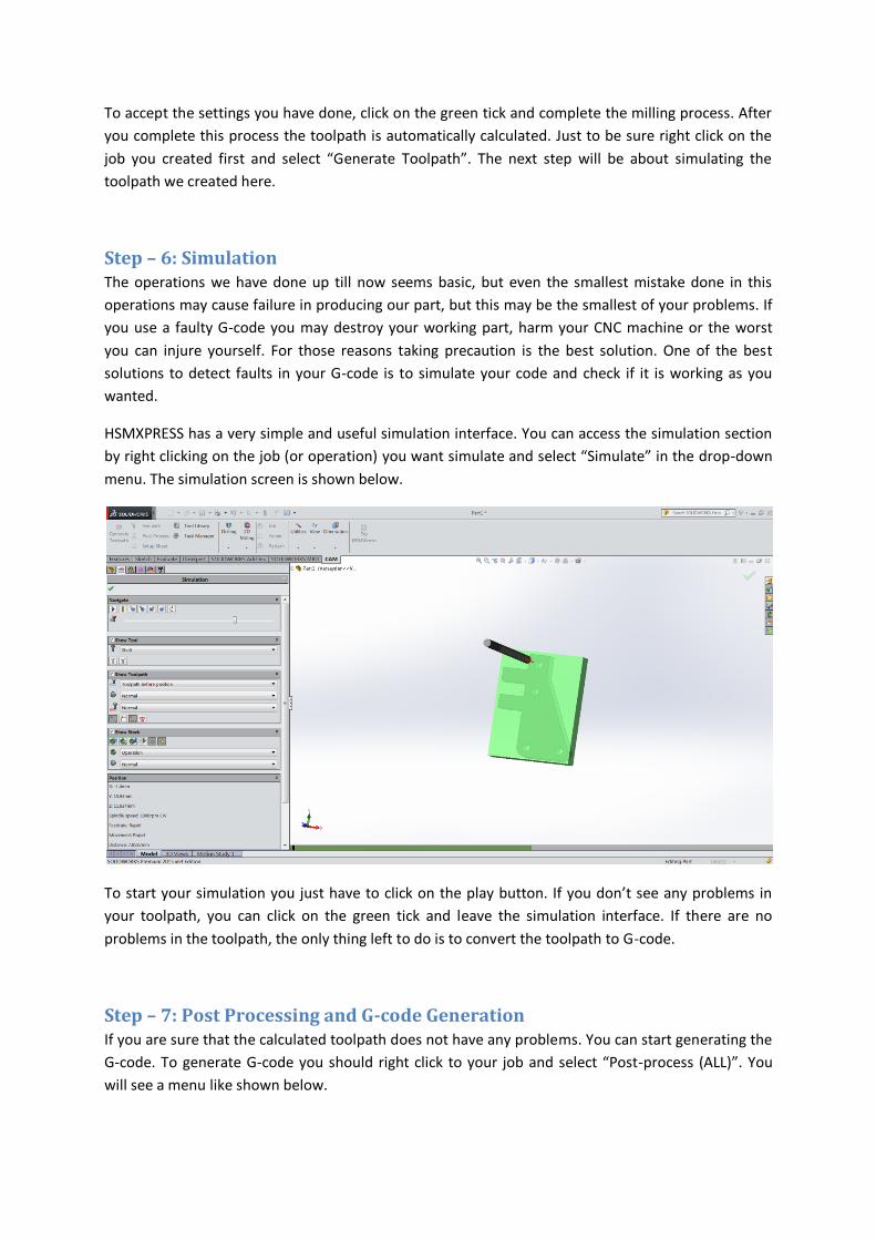
HSMXPRESS has a very simple and useful simulation interface. You can access the simulation section
by right clicking on the job (or operation) you want simulate and select “Simulate” in the drop-down
menu. The simulation screen is shown below.
To start your simulation you just have to click on the play button. If you don’t see any problems in
your toolpath, you can click on the green tick and leave the simulation interface. If there are no
problems in the toolpath, the only thing left to do is to convert the toolpath to G-code.
Step – 7: Post Processing and G-code Generation If you are sure that the calculated toolpath does not have any problems. You can start generating the
G-code. To generate G-code you should right click to your job and select “Post-process (ALL)”. You
will see a menu like shown below.
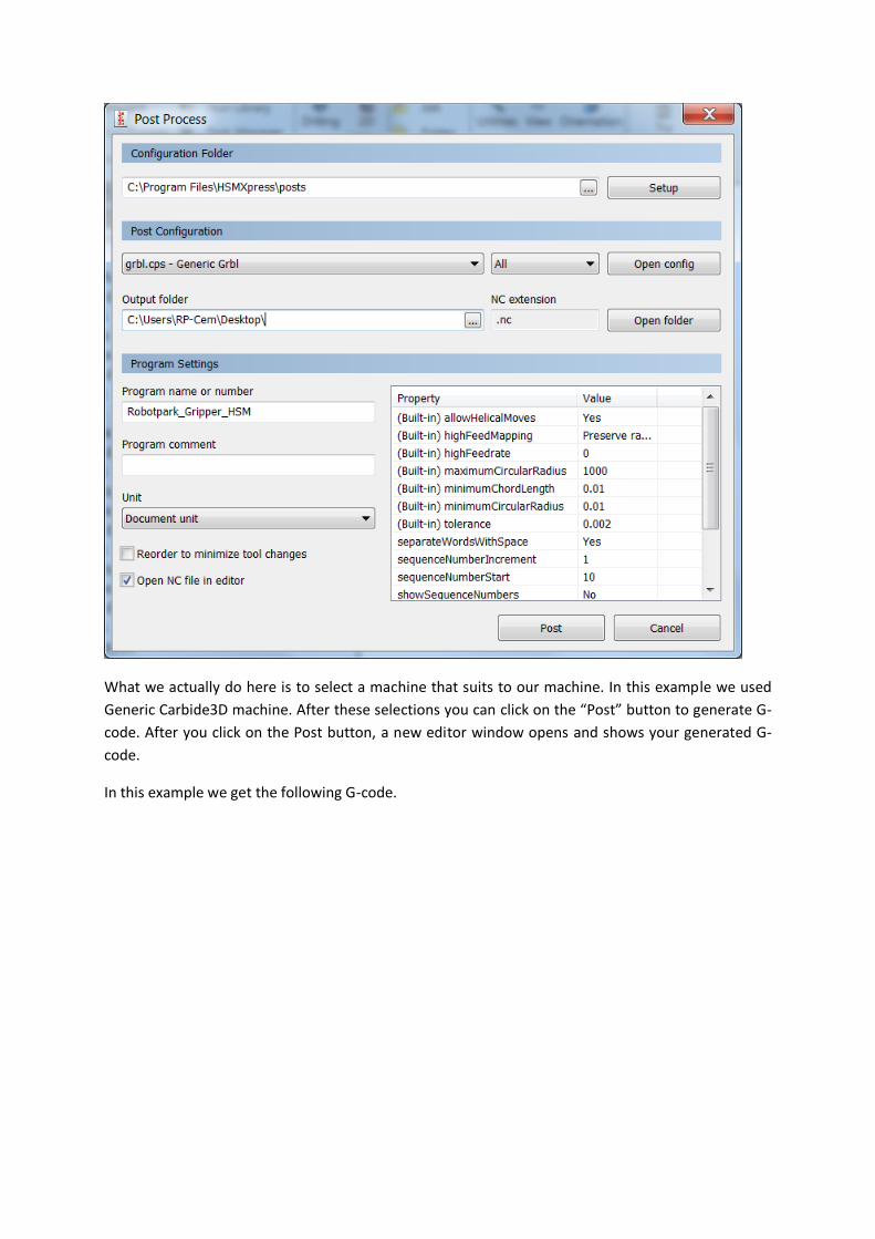
What we actually do here is to select a machine that suits to our machine. In this example we used
Generic Carbide3D machine. After these selections you can click on the “Post” button to generate G-
code. After you click on the Post button, a new editor window opens and shows your generated G-
code.
In this example we get the following G-code.
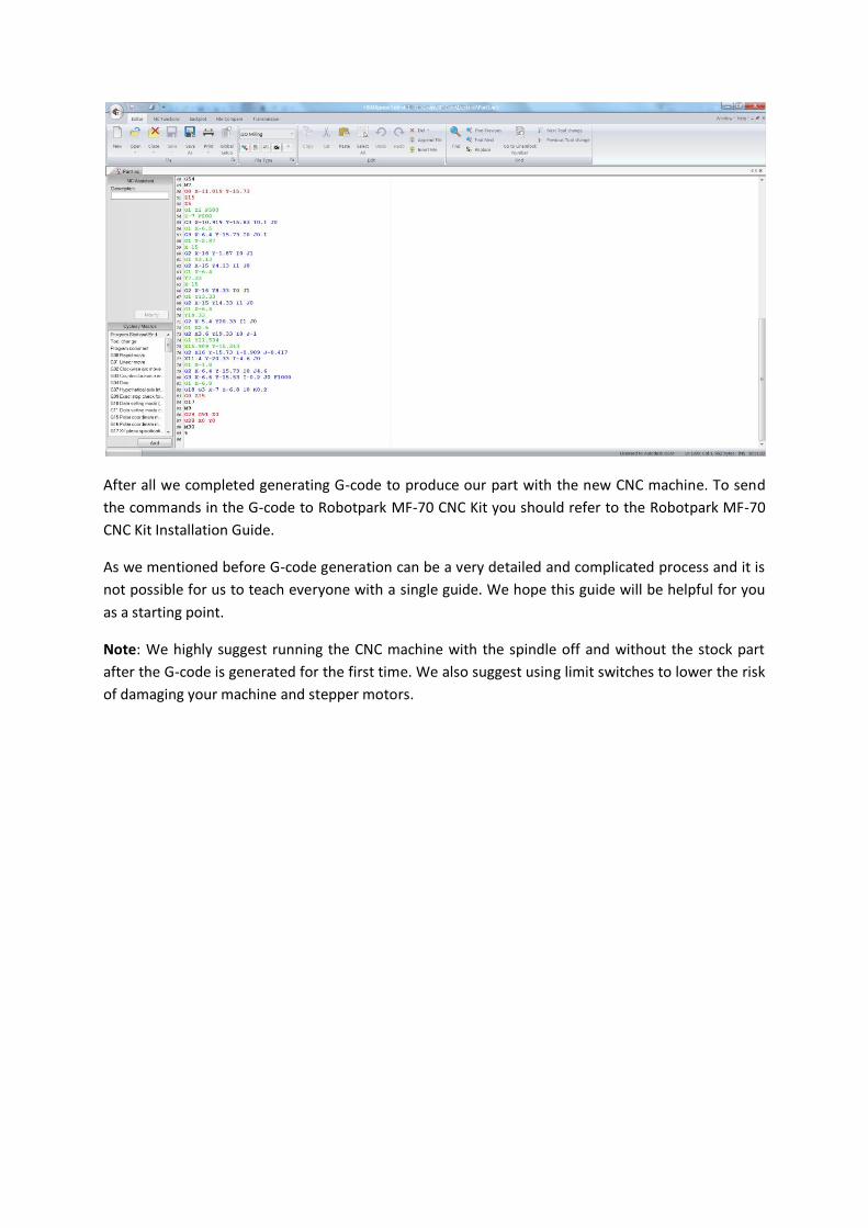
After all we completed generating G-code to produce our part with the new CNC machine. To send
the commands in the G-code to Robotpark MF-70 CNC Kit you should refer to the Robotpark MF-70
CNC Kit Installation Guide.
As we mentioned before G-code generation can be a very detailed and complicated process and it is
not possible for us to teach everyone with a single guide. We hope this guide will be helpful for you
as a starting point.
Note: We highly suggest running the CNC machine with the spindle off and without the stock part
after the G-code is generated for the first time. We also suggest using limit switches to lower the risk
of damaging your machine and stepper motors.