Embed Size (px)
Citation preview
G. D. Bibel
NDContact Stress Analysis of Spiral
Grand Forks,
Bevel Gears Using Finite A. Kumar
Element Analysis S. Reddy
University of Akron,
Akron, OH
A procedure is presented for performing three-dimensional stress analysis of spiral bevel gears in mesh using the finite element method. The procedure involves generating a finite element model by solving equations that identify tooth surface coordinates. Coordinate transformations are used to orientate the gear and pinion for gear meshing.
R. Handschuh Contact boundaiy conditions are simulated with gap elements. A solution technique for correct orientation of the gap elements is given. Example models and results are
Vehicle Propulsion Directorate,
U.S. Army Research Laboratory,presented.
Lewis Research Center,
Cleveland, OH
Introduction Spiral bevel gears are used to transmit power between
intersecting shafts. One such application is in helicopter transmission systems. In this critical application, the gears operate at relatively high rotational speed and transmit sub-stantial power (i.e., 1500 HP at 21,000 rpm).
Prior research has focused on spiral bevel gear geometry [1-6] to reduce vibration and kinematic error, improve manu-facturability and improve inspection. Stress analysis is an-other important area of ongoing research. Accurate predic-tion of contact stresses and tooth root/fillet stresses are important to increase reliability and reduce weight. Tooth flexibility will shift the contact zone and path, alter and change the contact area and stresses. Finite element analysis of gears in mesh, including tooth flexibility, will model con-tact stresses better than a Hertzian calculation.
Much effort has focused on predicting stresses in gears with the finite element method. Most of this work has in-volved parallel axis gears with two dimensional models. Only a few researchers have investigated finite element analysis of spiral bevel gears [7, 8].
Finite element analysis has been done on a single spiral bevel tooth using an assumed contact stress distribution [9]. The research reported here will utilize the numerical solu-tion for spiral bevel surface geometry to study gear meshing. Pinion tooth and gear tooth surfaces will be developed based on the gear manufacturing kinematics. The individual teeth are then rotated in space to create a multi-tooth model (4
Contributed by the Reliability. Stress Analysis. and Failure Prevention Committee for publication in the JOURNAL OF MECHANICAL DESIGN. Manuscript received May 1993; revised May 1994. Associate Technical Editor: T. H. Service.
Journal of Mechanical Design
gear and 3 pinion teeth). The tooth pair contact zones are modeled with gap elements. The model development proce-dure and finite element results are presented.
Equations for Tooth Surface Coordinates The system of equations, briefly summarized here, re-
quired to define the coordinates of a face-milled spiral bevel gear surface were developed by Handschuh and Litvin [9].
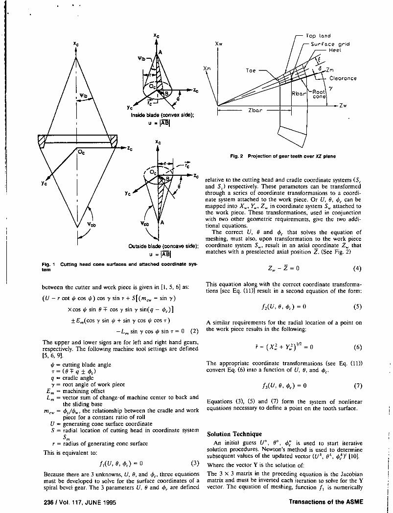
A conical cutting head, attached to a rotating cradle, swings through the work piece. Parameters U and 0 locate a point on the cutting head in coordinate system S. attached to the cutting head as shown in Fig. 1 and described by the following equations.
(r cot ti - U cos
I Usini/isinO I
r =( " (1) Usini,cosO I
I )
The roll angle of the cradle 4 is used to locate the rotating cradle with respect to the fixed machine coordinate system 5m Parameters U, U and 4, along with various machine tool settings can be used to completely define the location of a point on the cutting head in space.
Since the kinematic motion of cutting a gear is equivalent to the cutting head meshing with a simulated crown gear, an equation of meshing can be written in terms of a point on the cutting head (i.e., in terms of U, 0 and thc ). The equation of meshing for straight-sided cutters with a constant ratio of roll
JUNE 1995, Vol. 1171235
https://ntrs.nasa.gov/search.jsp?R=20150020428 2018-06-19T18:15:50+00:00Z
Yc
Inside blade (convex side);
zc
xc
grid
oronce
Zw
xc
Fig. 2 Projection of gear teeth over XZ plane
'C
Outside blade (concave side);
=II Fig. 1 CuttIng head cone surfaces and attached coordinate sys-tem
between the cutter and work piece is given in [1, 5, 6] as:
(U—rcot 'cos qi)cosysinr+S[(m.— sin y)
xcos q sin 0 cos y sin y sin(q - 4)]
relative to the cutting head and cradle coordinate systems (S and S) respectively. These parameters can be transformed through a series of coordinate transformations to a coordi-nate system attached to the work piece. Or U, 0, 4 can be mapped into X, Y,, Z in coordinate system S0. attached to the work piece. These transformations, used in conjunction with two other geometric requirements, give the two addi-tional equations.
The correct U, 0 and 4 that solves the equation of meshing, must also, upon transformation to the work piece coordinate system St..., result in an axial coordinate Z0, that matches with a preselected axial position Z. (See Fig. 2)
zw —= 0 (4)
This equation along with the correct coordinate transforma-tions [see Eq. (11)] result in a second equation of the form:
f2 (U, 6, cb) = 0 (5)
±Em(cos y sin i/i + sin ' cos i cos T) A similar requirements for the radial location of a point on
L m = 0 (2) the work piece results in the following:
The upper and lower signs are for left and right hand gears, respectively. The following machine tool settings are defined [5, 6, 9].
i/i = cutting blade angle r = (0 q ± 4) q = cradle angle y = root angle of work piece
Em = machining offset L m = vector sum of change of machine center to back and
the sliding base m 0. = d'/4, the relationship between the cradle and work
piece for a constant ratio of roll U = generating cone surface coordinate S = radial location of cutting head in coordinate system
Sm
r = radius of generating cone surface
This is equivalent to:
f1 (U, 0, d) = 0 (3)
Because there are 3 unknowns, U, 6, and 4, three equations must be developed to solve for the surface coordinates of a spiral bevel gear. The 3 parameters U, 0 and are defined
(6)
The appropriate coordinate transformations (see Eq. (11)) convert Eq. (6) into a function of U, 6, and 4.
f3 (U, 0, 4') = 0 (7)
Equations (3), (5) and (7) form the system of nonlinear equations necessary to define a point on the tooth surface.
Solution Technique An initial guess U0 , 0, cb° is used to start iterative
solution procedures. Newton's method is used to determine subsequent values of the updated vector (U k , 0, 4)' [101. Where the vector Y is the solution of: The 3 X 3 matrix in the preceding equation is the Jacobian matrix and must be inverted each iteration to solve for the Y vector. The equation of meshing, function f1 is numerically
236! Vol. 117, JUNE 1995 Transactions of the ASME
differentiated directly to find the terms for the
(uk' (u\(ykI)
to=/ok+)Y1S (8) 4ki 4k-l1
_J " CI C )
df1(U') df (9k_I) df2(4)
df2(U k_I ) df(Ok_I)
dU duO
df3(U"') df(O'1)
dU do
gk—I
= f2(u', 9k—I 4 k_I ) (9) f3 (Uk1 , akl , kI)J
Jacobian matrix. Function f2 and f3 cannot be directly differentiated with respect to U, 0 and 4. After each itera-tion ucI, 9k I 4,! (in the cutting head coordinate system Sc) are transformed into the work piece coordinate system, S w,, with the series of coordinate transformations as given in Eq. (11).
l (rcotii—Ucosqi
= [M.,c ] Usin !/isin 0 (10)
I, JUsin4icosO )
where:
[M,.,] = [M,.,af(cbc)][Mop][Mpm][Mmsf(d'c)J[Msc] (11)
Each matrix EM] above represents a transformation from one coordinate system to another. (See Appendix I for the spe-cific matrices.)
Functions f2 and f1 are evaluated by starting with an initial Uk, 0k and 4, performing the transformation in Eq. (11) and evaluating Eqs. (4) and (6). The numerical differen-
tiation of f, and f3 is performed by transforming U' + mc, + in 4 + inc (where inc is a small increment appropri-
ate for numerical differentiation into X, + mc, Y,., + mc, Z,. + inc. Equations (4) and (6) are then used to evaluate the numerical differentiation. Function f, f2, f3 and the partial derivatives of 11, f2, f3 required to the Jacobian matrix are updated each iteration. The iteration continues until the Y vector is less than a predetermined tolerance. This completes the solution techniques for a single point on the spiral bevel gear surface.
The four corners of the active profile are identified from the tooth geometry plane as shown in Fig. 2. Point I on the surface is chosen to be the lowest point of the active profile on the toe end. The initial guess to start the procedure has to be sufficiently close to the correct solution for convergence to occur. The solution for the first point proves to be an adequate initial guess for any subsequent points on the surface.
Subsequent interior surface points are found by increment-ing r = (X 2 + Y 2 )"2 and Z. By adjusting the increments used, a surface mesh of any density can be calculated. The process is repeated four times for each of four surfaces; gear convex, gear concave, pinion convex and pinion concave. Software was written to solve for the tooth surface coordi-nates. Additional software converted the surface coordinates into input commands for the 3D solid modeler PATRAN [11]. PATRAN was used to create the nodes and elements for the FE code NASTRAN [12].
Since all four surfaces are generated independently, addi-tional matrix transformations are required to obtain the appropriate orientation for meshing. The proper convex and concave surface orientation (for both the gear and pinion) is found by fixing the concave surface and rotating the convex surface until the correct tooth thickness is obtained. The correct angle of rotation is obtained by matching the tooth top land thickness with the desired value.
Gear and Pinion Orientations Required For Meshing After generating the pinion and gear surface as described
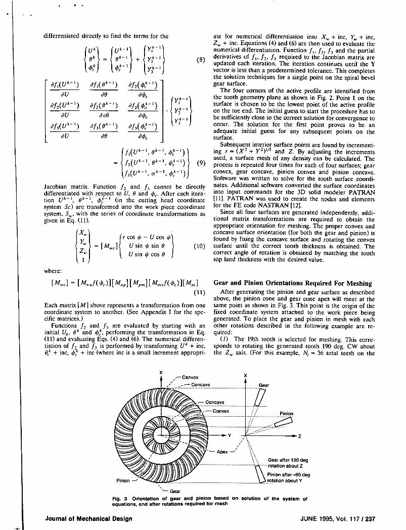
above, the pinion cone and gear cone apex will meet at the same point as shown in Fig. 3. This point is the origin of the fixed coordinate system attached to the work piece being generated. To place the gear and pinion in mesh with each other rotations described in the following example are re-quired:
(1) The 19th tooth is selected for meshing. This corre-sponds to rotating the generated tooth 190 deg. CW about the Z,, axis. (For this example, Iv = 36 total teeth on the
d4 I I (y1k_I
df2 ( 4 ') I . ) I yk_IJ
df3(4')
dC
,..—Convex
Concave Gear
-1t on
_______ __________________
_
Fig. 3 Orientation of gear and pinion based on solution of the system of equations, and after rotations required for mesh
Journal of Mechanical Design JUNE 1995, Vol. 1171237
.
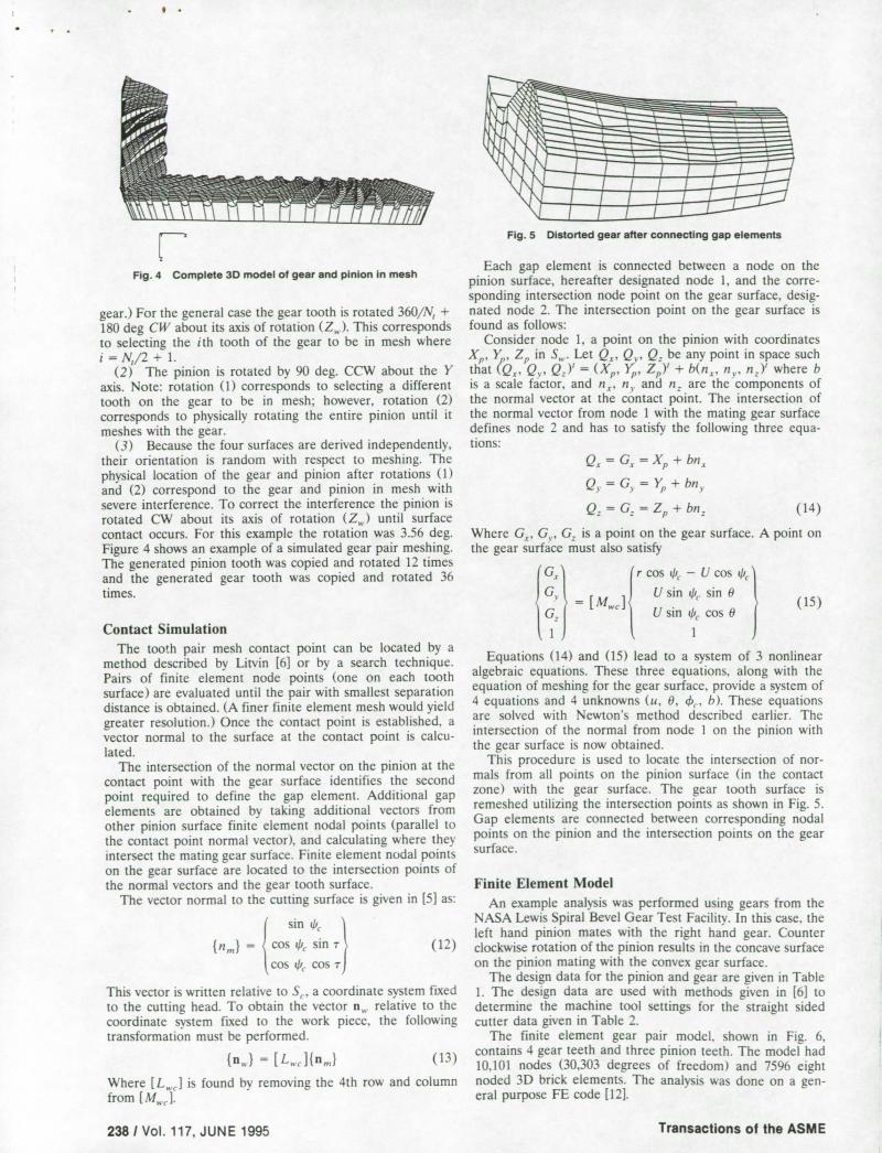
P Fig. 4 Complete 3D model of gear and pinion in mesh
gear.) For the general case the gear tooth is rotated 360/Pç + 180 deg CW about its axis of rotation (4). This corresponds to selecting the ith tooth of the gear to be in mesh where i = N1/2 + 1.
(2) The pinion is rotated by 90 deg. CCW about the Y axis. Note: rotation (1) corresponds to selecting a different tooth on the gear to be in mesh; however, rotation (2) corresponds to physically rotating the entire pinion until it meshes with the gear.
(3) Because the four surfaces are derived independently, their orientation is random with respect to meshing. The physical location of the gear and pinion after rotations (1) and (2) correspond to the gear and pinion in mesh with severe interference. To correct the interference the pinion is rotated CW about its axis of rotation (4) until surface contact occurs. For this example the rotation was 3.56 deg. Figure 4 shows an example of a simulated gear pair meshing. The generated pinion tooth was copied and rotated 12 times and the generated gear tooth was copied and rotated 36 times.
Contact Simulation The tooth pair mesh contact point can be located by a
method described by Litvin [6] or by a search technique. Pairs of finite element node points (one on each tooth surface) are evaluated until the pair with smallest separation distance is obtained. (A finer finite element mesh would yield greater resolution.) Once the contact point is established, a vector normal to the surface at the contact point is calcu-lated.
The intersection of the normal vector on the pinion at the contact point with the gear surface identifies the second point required to define the gap element. Additional gap elements are obtained by taking additional vectors from other pinion surface finite element nodal points (parallel to the contact point normal vector), and calculating where they intersect the mating gear surface. Finite element nodal points on the gear surface are located to the intersection points of the normal vectors and the gear tooth surface.
The vector normal to the cutting surface is given in [5] as:
sin i/it
{11m} cos sin r (12)
cos i/it cos r
This vector is written relative to S. a coordinate system fixed to the cutting head. To obtain the vector n relative to the coordinate system fixed to the work piece. the following transformation must be performed.
{n } = [L]{n,) (13)
Where [L,j is found by removing the 4th row and column from [M 1.
Fig. 5 Distorted gear after connecting gap elements
Each gap element is connected between a node on the pinion surface, hereafter designated node 1, and the corre-sponding intersection node point on the gear surface, desig-nated node 2. The intersection point on the gear surface is found as follows:
Consider node 1, a point on the pinion with coordinates X,,, Y, Z, in S. Let Q. Q, Q. be any point in space such that (Q. QY = (Xe . )', Z,,Y + b(n, n c , n)' where b is a scale factor, and n, n and n. are the components of the normal vector at the contact point. The intersection of the normal vector from node I with the mating gear surface defines node 2 and has to satisfy the following three equa-tions:
Q = = X + bn
Q = G = + bn
Q=G.=Z+bn. (14)
Where G, G % , G. is a point on the gear surface. A point on the gear surface must also satisfy
(G \ r cos i/k. - U cos ' G( Usini/sin6
= [MJ ì (15) <1 G.( Un4cosO I
U) Equations (14) and (15) lead to a system of 3 nonlinear
algebraic equations. These three equations, along with the equation of meshing for the gear surface, provide a system of 4 equations and 4 unknowns (u. 6, . b). These equations are solved with Newton's method described earlier. The intersection of the normal from node I on the pinion with the gear surface is now obtained.
This procedure is used to locate the intersection of nor-mals from all points on the pinion surface (in the contact zone) with the gear surface. The gear tooth surface is remeshed utilizing the intersection points as shown in Fig. 5. Gap elements are connected between corresponding nodal points on the pinion and the intersection points on the gear surface.
Finite Element Model
An example analysis was performed using gears from the NASA Lewis Spiral Bevel Gear Test Facilit y . In this case, the left hand pinion mates with the right hand gear. Counter clockwise rotation of the pinion results in the concave surface on the pinion mating with the convex gear surface.
The design data for the pinion and gear are given in Table 1. The design data are used with methods given in [6] to determine the machine tool settings for the straight sided cutter data given in Table 2.
The finite element gear pair model, shown in Fi g . 6. contains 4 gear teeth and three pinion teeth. The model had 10.101 nodes (30.303 degrees of freedom) and 7596 eight noded 3D brick elements. The analysis was done on a gen-eral purpose FE code [12].
238 I Vol. 117, JUNE 1995 Transactions of the ASME
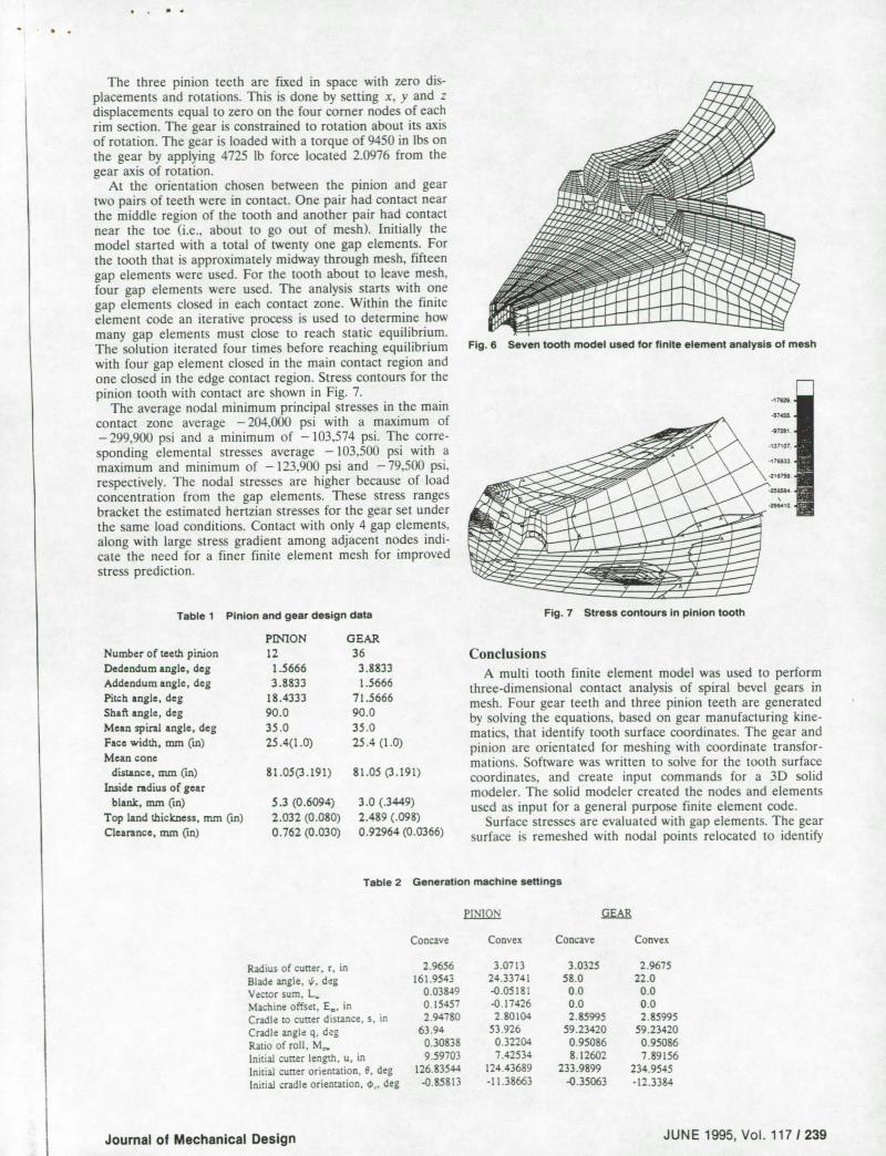
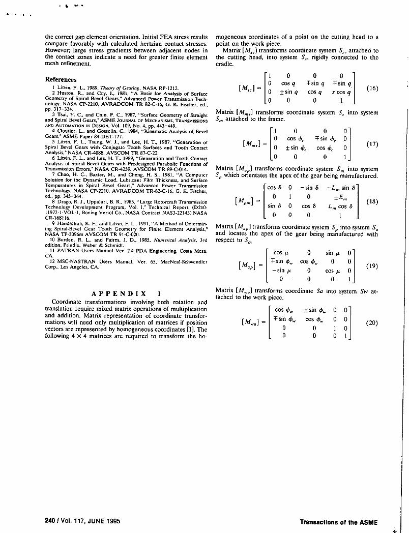
Fig. 7 Stress contours in pinion tooth
I.] Ii
The three pinion teeth are fixed in space with zero dis-placements and rotations. This is done by setting x, y and z displacements equal to zero on the four corner nodes of each rim section. The gear is constrained to rotation about its axis of rotation. The gear is loaded with a torque of 9450 in lbs on the gear by applying 4725 lb force located 2.0976 from the gear axis of rotation.
At the orientation chosen between the pinion and gear two pairs of teeth were in contact. One pair had contact near the middle region of the tooth and another pair had contact near the toe (i.e., about to go out of mesh). Initially the model started with a total of twenty one gap elements. For the tooth that is approximately midway through mesh, fifteen gap elements were used. For the tooth about to leave mesh, four gap elements were used. The analysis starts with one gap elements closed in each contact zone. Within the finite element code an iterative process is used to determine how many gap elements must close to reach static equilibrium. The solution iterated four times before reaching equilibrium with four gap element closed in the main contact region and one closed in the edge contact region. Stress contours for the pinion tooth with contact are shown in Fig. 7.
The average nodal minimum principal stresses in the main contact zone average - 204.000 psi with a maximum of - 299.900 psi and a minimum of - 103,574 psi. The corre-sponding elemental stresses average - 103,500 psi with a maximum and minimum of -123,900 psi and -79,500 psi. respectively. The nodal stresses are higher because of load concentration from the gap elements. These stress ranges bracket the estimated hertzian stresses for the gear set under the same load conditions. Contact with only 4 gap elements. along with large stress gradient among adjacent nodes indi-cate the need for a finer finite element mesh for improved stress prediction.
Table 1 Pinion and gear design data
PINiON GEAR Number of teeth pinion 12 36 Dedendumangle,deg 1.5666 3.8833 Addendum angle, deg 3.8833 1.5666 Pitch angle, deg 18.4333 71.5666 Shaft angle, deg 90.0 90.0 Mean spiral angle, deg 35.0 35.0 Face width, mm c) 25.4(1.0) 25.4 (1.0) Mean cone
djstance,mmcin) 81.05(3.191) 81.05(3.191) Inside radius of gear
blank, mm (in) 5.3 (0.6094) 3.0 (.3449) Top land thickness, mm (in) 2.032 (0.080) 2.489 (.098) Clearance, mm (in) 0.762 (0.030) 0.92964 (0.0366)
Fig. 6 Seven tooth model used for finite element analysis of mesh
Conclusions A multi tooth finite element model was used to perform
three-dimensional contact analysis of spiral bevel gears in mesh. Four gear teeth and three pinion teeth are generated by solving the equations. based on gear manufacturing kine-matics, that identify tooth surface coordinates. The gear and pinion are orientated for meshing with coordinate transfor-mations. Software was written to solve for the tooth surface coordinates, and create input commands for a 3D solid modeler. The solid modeler created the nodes and elements used as input for a general purpose finite element code.
Surface stresses are evaluated with gap elements. The gear surface is remeshed with nodal points relocated to identify
Table 2 Generation machine settings
PINION
Concave Convex Concave Convex
Radius of cutter, r, in 2.9656 3.07 13 3.0325 2.9675 Blade angle. ', deg 161.9543 24.33741 58.0 22.0 Vector sum, L 0.03849 -0.05181 0.0 0.0 Machine offset, E_, in 0 15457 -0.17426 0.0 0.0 Cradle to cutter distance, s, in 2.94780 2.80104 2.85995 2.85995 Cradle angle q, deg 63.94 53.926 59.23420 59.23420 Ratio of roll, M,.. 0.30838 0.32204 0.95086 0.95086 initial cutter length. u, in 9.59703 7.42534 8.12602 7.89156 Initial cutter orientation, 8. deg 126.83544 124.43689 233.9899 234.9545 Initial cradle orientation. .., deg -0.85813 -11.38663 -0.35063 -12.3384
Journal of Mechanical Design JUNE 1995, Vol. 117 I 239
I • 4 ,
the correct gap element orientation. Initial FEA stress results compare favorably with calculated hertzian contact stresses. However; large stress gradients between adjacent nodes in the contact zones indicate a need for greater finite element mesh refinement.
References I Litvin, F. L., 1989, Theory of Gearing, NASA RP-1212. 2 Huston, R., and Coy, J., 1981, "A Basic for Analysis of Surface
Geometry of Spiral Bevel Gears," Advanced Power Transmission Tech-nology, NASA CP-2210, AVRADCOM TR 82-C-16, G. K. Fischer, ed., pp. 317-334.
3 Tsai, Y. C., and Chin. P. C., 1987, "Surface Geometry of Straight and Spiral Bevel Gears," ASME JOURNAL OF MECHANISMS, TRANSMISSIONS AND AUTOMATION IN DESIGN, Vol. 109, No. 4, pp. 443-449.
4 Cloutier, L., and Gosselin, C.. 1984, "Kinematic Analysis of Bevel Gears," ASME Paper 84-DET-177.
5 Litvin, F. L., Tsung, W. J., and Lee, H. T., 1987, "Generation of Spiral Bevel Gears with Conjugate Tooth Surfaces and Tooth Contact Analysis," NASA CR-4088, AVSCOM TR 87-C.22.
6 Lit-yin, F. L., and Lee, H. T.. 1989, "Generation and Tooth Contact Analysis of Spiral Bevel Gears with Predesigned Parabolic Functions of Transmission Errors," NASA CR-4259, AVSCOM TR 89-C-014.
7 Chao, H. C.. Baxter, M., and Cheng, H. S., 1981, "A Computer Solution for the Dynamic Load. Lubricant Film Thickness, and Surface Temperatures in Spiral Bevel Gears," Advanced Power Transmission Technology, NASA CP-2210, AVRADCOM TR-82-C-16, G. K. Fischer, ed., pp. 345-364.
8 Drago, R. J., Uppaluri, B. R., 1983, "Large Rotorcraft Transmission Technology Development Program, Vol. I." Technical Report. (D210. 11972 . 1-VOL-I, Boeing Vertol Co.. NASA Contract NAS3-22143) NASA CR-168116.
9 Handschuh, R. F.. and Litvin, F. L., 1991, "A Method of Determin-ing Spiral-Bevel Gear Tooth Geometry for Finite Element Analysis," NASA TP-3096m AVSCOM TR 91-C-020.
10 Burden, R. L., and Faires, J. D., 1985, Numerical Analysis. 3rd edition, Prindle, Weber & Schmidt.
II PATRAN Users Manual Ver. 2.4 PDA Engineering, Costa Mesa, CA.
12 MSC-NASTRAN Users Manual, Ver. 65, MacNeal-Schwendler Corp., Los Angeles. CA.
mogeneous coordinates of a point on the cutting head to a point on the work piece.
Matrix [M5] transforms coordinate system S, attached to the cutting head, into system S, rigidly connected to the cradle.
11 0 0 0 1 I 0 cos q sin q sin q I
[M5] = I 0 ±sin q cos q s cos q I (16)
L 0 0 0 1 ]
Matrix [Mms ] transforms coordinate system S 5 into system m attached to the frame.
11 0 0 01 lo COS I c Fsin4 01
[Mms] = 0 ±sin 4 cos 4' 0 I (17)
0 0 0 i] Matrix [Map ] transforms coordinate system Sm into system S,, which orientates the apex of the gear being manufactured.
Icos 6 0 —sin 6 L m sin 61 0 1 0 ±Em I [Mpm]
= sin 6 0 cos 6 Lm(18)
L° 0 0 1 ] Matrix [Map ] transforms coordinate system Si,, into system Sa and locates the apex of the gear being manufactured with respect to m
I cosz 0 sing 01
[M0] =Fsin c/
i .cos4 0 01 (19)
SIfl/A. 0 cos 01 L 0 0 0 ii
APPENDIX I Coordinate transformations involving both rotation and
translation require mixed matrix operations of multiplication and addition. Matrix representation of coordinate transfor-mations will need only multiplication of matrices if position vectors are represented by homogeneous coordinates [1]. The following 4 x 4 matrices are required to transform the ho-
Matrix [Mwa ] transforms cooi tached to the work piece.
cos
[M ]=sin4
0 0
dinate Sa into system Sw at-
±sin 0 0
cos 4,, 0 0 (20)
0 10
0 01
240! Vol. 117, JUNE 1995
Transactions of the ASME