Embed Size (px)
Citation preview
SwissFEL instrument ESB femtosecond pump-probe diffraction and scattering
G. Ingold, , J. Rittmann, , P. Beaud, M. Divall, C. Erny, U. Flechsig, R. Follath, C. P. Hauri, S. Hunziker, P.Juranic, A. Mozzanica, B. Pedrini, L. Sala, L. Patthey, B. D. Patterson, and R. Abela,
Citation: AIP Conference Proceedings 1741, 030039 (2016); doi: 10.1063/1.4952862View online: http://dx.doi.org/10.1063/1.4952862View Table of Contents: http://aip.scitation.org/toc/apc/1741/1Published by the American Institute of Physics
SwissFEL Instrument ESBFemtosecond Pump-Probe Diffraction and Scattering
G. Ingold1,a), J. Rittmann1,b), P. Beaud1, M. Divall1, C. Erny1, U. Flechsig1, R.Follath1, C. P. Hauri1, S. Hunziker1, P. Juranic1, A. Mozzanica1, B. Pedrini1, L.
Sala1, L. Patthey1, B.D. Patterson1 and R. Abela1,c)
1SwissFEL, Paul Scherrer Institut, 5232 Villigen PSI, Switzerland
a)Corresponding author: [email protected])[email protected]
c)URL: http://www.psi.ch/swissfel
Abstract. The ESB instrument at the SwissFEL ARAMIS hard X-ray free electron laser is designed to perform pump-probeexperiments in condensed matter and material science employing photon-in and photon-out techniques. It includes a femtosecondoptical laser system to generate a variety of pump beams, a X-ray optical scheme to tailor the X-ray probe beam, shot-to-shotdiagnostics to monitor the X-ray intensity and arrival time, and two endstations operated at a single focus position that includemulti-purpose sample environments and 2D pixel detectors for data collection.
INTRODUCTION
Combining femtosecond (fs) optical laser excitation and X-ray scattering techniques allows to study the stimulatedreponse of functional crystalline materials in the time domain with atomic resolution on a sub-ps timescale. Novelelectronic properties in such materials reflect a balance between several correlated interactions of long-range order,including charge and orbital ordering, magnetism, and coupling to the lattice. One way to clarify cause and effect insuch coupled systems is to selectively pump and probe specific modes by tailored pulses and by tuning the systemby adjusting thermodynamic variables such as temperature, magnetic field or pressure. On a sub-ps timescale theelectronic and thermal response are well separated. This allows to study electronic induced switching in multiferroicsand non-thermally driven non-equilibirum phase transitions to new electronic or magnetic phases in correlated electronsystems by employing flexible pump and probe pulses in terms of wavelength, polarization and intensity. In a pump-probe experiment the time response - which for coherent excitation is oscillatory followed by dephasing and relaxation- is measured by precisely varying the separation between the pump and probe. Optical and THz pump pulses arederived from a fs laser system. The sample is probed by fs X-ray pulses from SwissFEL in SASE mode by time-resolved resonant and non-resonant diffraction (tr(R)XRD) and diffuse scattering (trDS), or in self-seeding mode byresonant inelastic X-ray scattering (trRIXS) in the future.
ESB INSTRUMENT
The ESB instrument [1] is operated in the energy range 4.5-12.4 keV of the fundamental. SwissFEL ARAMIS normalmode of operation is SASE in high (200 pC) and low charge (10 pC) mode [2]. At 7 keV the flux and pulse length is1.3x1012 ph/s/0.1% bw & 5 fs FWHM (10 pC, 100 Hz) and 2.1x10¹³ ph/s/0.1% bw & 50 fs FWHM (200 pC, 100 Hz),respectively. Other modes of operation are the large bandwidth mode (2-4% bw), the self-seeding mode providing anorder of magnitude higher spectral brightness for trRIXS, and the attosecond mode providing a fully coherent singlespike with a pulse length of 0.2 fs FWHM for sub-fs experiments without crystal optics.
Proceedings of the 12th International Conference on Synchrotron Radiation Instrumentation – SRI2015AIP Conf. Proc. 1741, 030039-1–030039-4; doi: 10.1063/1.4952862
Published by AIP Publishing. 978-0-7354-1398-6/$30.00
030039-1
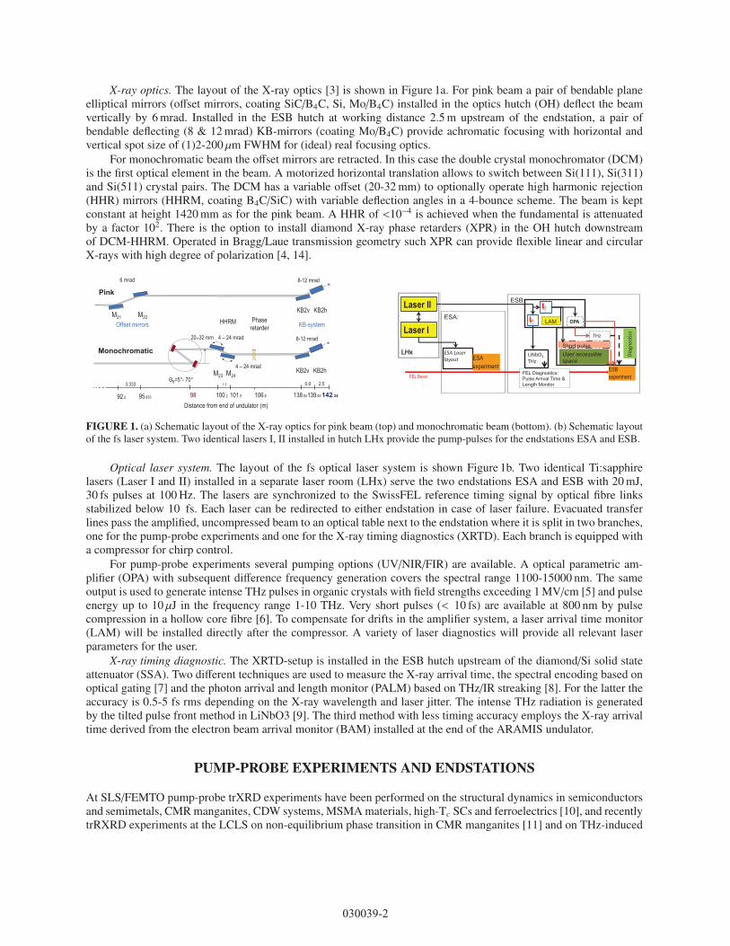
X-ray optics. The layout of the X-ray optics [3] is shown in Figure 1a. For pink beam a pair of bendable planeelliptical mirrors (offset mirrors, coating SiC/B4C, Si, Mo/B4C) installed in the optics hutch (OH) deflect the beamvertically by 6 mrad. Installed in the ESB hutch at working distance 2.5 m upstream of the endstation, a pair ofbendable deflecting (8 & 12 mrad) KB-mirrors (coating Mo/B4C) provide achromatic focusing with horizontal andvertical spot size of (1)2-200 μm FWHM for (ideal) real focusing optics.
For monochromatic beam the offset mirrors are retracted. In this case the double crystal monochromator (DCM)is the first optical element in the beam. A motorized horizontal translation allows to switch between Si(111), Si(311)and Si(511) crystal pairs. The DCM has a variable offset (20-32 mm) to optionally operate high harmonic rejection(HHR) mirrors (HHRM, coating B4C/SiC) with variable deflection angles in a 4-bounce scheme. The beam is keptconstant at height 1420 mm as for the pink beam. A HHR of <10−4 is achieved when the fundamental is attenuatedby a factor 102. There is the option to install diamond X-ray phase retarders (XPR) in the OH hutch downstreamof DCM-HHRM. Operated in Bragg/Laue transmission geometry such XPR can provide flexible linear and circularX-rays with high degree of polarization [4, 14].
Distance from end of undulator (m) 95.833 92.5
0.9 3.333
142.34 138.94 139.84
2.5
98 100.2 101.5
1.3
106.8
Pink
M21 M22
8-12 mrad
KB2v KB2h
6 mrad
KB-system HHRM Offset mirrors Phase
retarder
Monochromatic 8-12 mrad
KB2v KB2h
B=5°- 70°
20–32 mm 4 – 24 mrad
4 – 24 mrad M24 M23
ESB experiment
ESB:
FEL Diagnostics: Pulse Arrival Time & Length Monitor
LiNbO3 THz
OPA
THz
Short pulse
ES
LAM
Diag
nost
ics
User accessible space
LHx
Laser II
Laser I ESA:
ESA Laser layout ESA
experiment FEL Beam
FIGURE 1. (a) Schematic layout of the X-ray optics for pink beam (top) and monochromatic beam (bottom). (b) Schematic layoutof the fs laser system. Two identical lasers I, II installed in hutch LHx provide the pump-pulses for the endstations ESA and ESB.
Optical laser system. The layout of the fs optical laser system is shown Figure 1b. Two identical Ti:sapphirelasers (Laser I and II) installed in a separate laser room (LHx) serve the two endstations ESA and ESB with 20 mJ,30 fs pulses at 100 Hz. The lasers are synchronized to the SwissFEL reference timing signal by optical fibre linksstabilized below 10 fs. Each laser can be redirected to either endstation in case of laser failure. Evacuated transferlines pass the amplified, uncompressed beam to an optical table next to the endstation where it is split in two branches,one for the pump-probe experiments and one for the X-ray timing diagnostics (XRTD). Each branch is equipped witha compressor for chirp control.
For pump-probe experiments several pumping options (UV/NIR/FIR) are available. A optical parametric am-plifier (OPA) with subsequent difference frequency generation covers the spectral range 1100-15000 nm. The sameoutput is used to generate intense THz pulses in organic crystals with field strengths exceeding 1 MV/cm [5] and pulseenergy up to 10 μJ in the frequency range 1-10 THz. Very short pulses (< 10 fs) are available at 800 nm by pulsecompression in a hollow core fibre [6]. To compensate for drifts in the amplifier system, a laser arrival time monitor(LAM) will be installed directly after the compressor. A variety of laser diagnostics will provide all relevant laserparameters for the user.
X-ray timing diagnostic. The XRTD-setup is installed in the ESB hutch upstream of the diamond/Si solid stateattenuator (SSA). Two different techniques are used to measure the X-ray arrival time, the spectral encoding based onoptical gating [7] and the photon arrival and length monitor (PALM) based on THz/IR streaking [8]. For the latter theaccuracy is 0.5-5 fs rms depending on the X-ray wavelength and laser jitter. The intense THz radiation is generatedby the tilted pulse front method in LiNbO3 [9]. The third method with less timing accuracy employs the X-ray arrivaltime derived from the electron beam arrival monitor (BAM) installed at the end of the ARAMIS undulator.
PUMP-PROBE EXPERIMENTS AND ENDSTATIONS
At SLS/FEMTO pump-probe trXRD experiments have been performed on the structural dynamics in semiconductorsand semimetals, CMR manganites, CDW systems, MSMA materials, high-Tc SCs and ferroelectrics [10], and recentlytrRXRD experiments at the LCLS on non-equilibrium phase transition in CMR manganites [11] and on THz-induced
030039-2
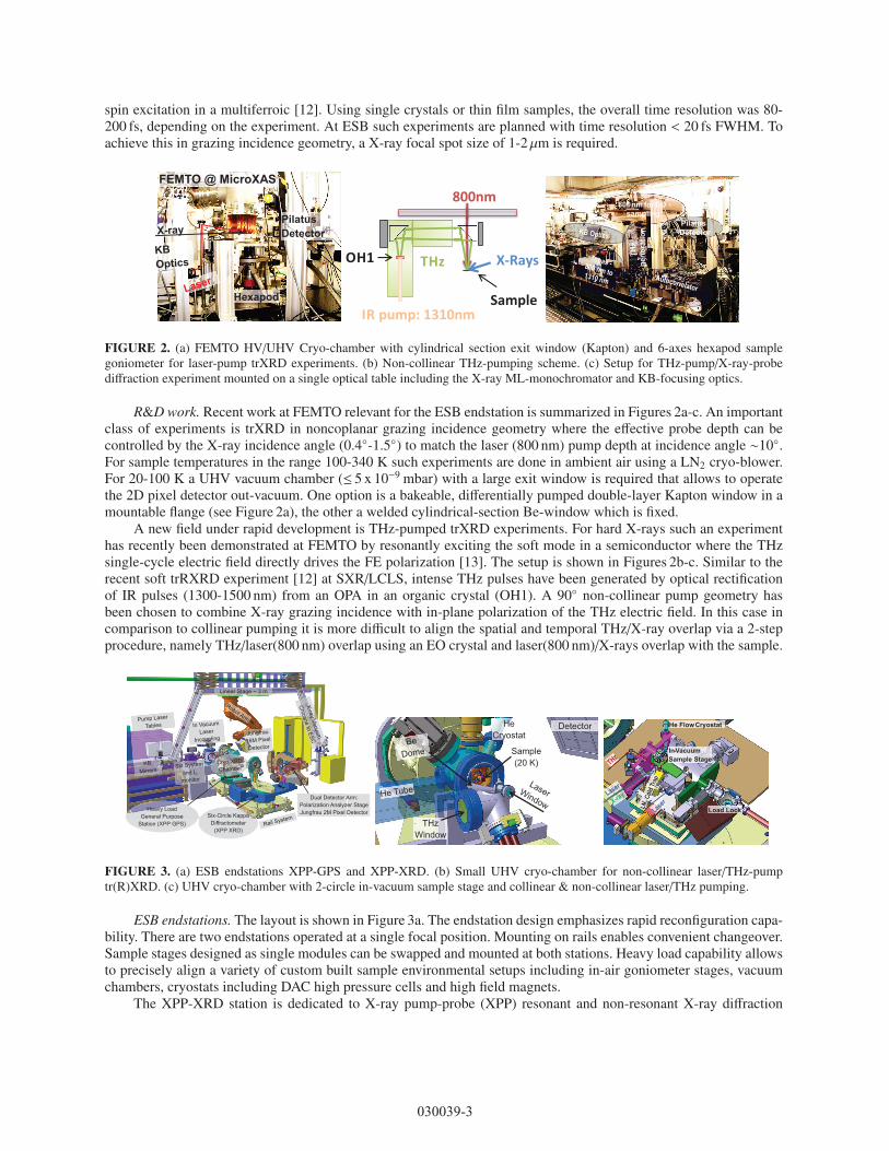
spin excitation in a multiferroic [12]. Using single crystals or thin film samples, the overall time resolution was 80-200 fs, depending on the experiment. At ESB such experiments are planned with time resolution < 20 fs FWHM. Toachieve this in grazing incidence geometry, a X-ray focal spot size of 1-2 μm is required.
FIGURE 2. (a) FEMTO HV/UHV Cryo-chamber with cylindrical section exit window (Kapton) and 6-axes hexapod samplegoniometer for laser-pump trXRD experiments. (b) Non-collinear THz-pumping scheme. (c) Setup for THz-pump/X-ray-probediffraction experiment mounted on a single optical table including the X-ray ML-monochromator and KB-focusing optics.
R&D work. Recent work at FEMTO relevant for the ESB endstation is summarized in Figures 2a-c. An importantclass of experiments is trXRD in noncoplanar grazing incidence geometry where the effective probe depth can becontrolled by the X-ray incidence angle (0.4◦-1.5◦) to match the laser (800 nm) pump depth at incidence angle ∼10◦.For sample temperatures in the range 100-340 K such experiments are done in ambient air using a LN2 cryo-blower.For 20-100 K a UHV vacuum chamber (≤ 5 x 10⁻⁹ mbar) with a large exit window is required that allows to operatethe 2D pixel detector out-vacuum. One option is a bakeable, differentially pumped double-layer Kapton window in amountable flange (see Figure 2a), the other a welded cylindrical-section Be-window which is fixed.
A new field under rapid development is THz-pumped trXRD experiments. For hard X-rays such an experimenthas recently been demonstrated at FEMTO by resonantly exciting the soft mode in a semiconductor where the THzsingle-cycle electric field directly drives the FE polarization [13]. The setup is shown in Figures 2b-c. Similar to therecent soft trRXRD experiment [12] at SXR/LCLS, intense THz pulses have been generated by optical rectificationof IR pulses (1300-1500 nm) from an OPA in an organic crystal (OH1). A 90◦ non-collinear pump geometry hasbeen chosen to combine X-ray grazing incidence with in-plane polarization of the THz electric field. In this case incomparison to collinear pumping it is more difficult to align the spatial and temporal THz/X-ray overlap via a 2-stepprocedure, namely THz/laser(800 nm) overlap using an EO crystal and laser(800 nm)/X-rays overlap with the sample.
Dual Detector Arm: Polarization Analyzer Stage Jungfrau 2M Pixel Detector
Linear Stage ~ 3 m
Heavy Load General Purpose
Station (XPP GPS) Six-Circle Kappa
Diffractometer (XPP XRD)
FIGURE 3. (a) ESB endstations XPP-GPS and XPP-XRD. (b) Small UHV cryo-chamber for non-collinear laser/THz-pumptr(R)XRD. (c) UHV cryo-chamber with 2-circle in-vacuum sample stage and collinear & non-collinear laser/THz pumping.
ESB endstations. The layout is shown in Figure 3a. The endstation design emphasizes rapid reconfiguration capa-bility. There are two endstations operated at a single focal position. Mounting on rails enables convenient changeover.Sample stages designed as single modules can be swapped and mounted at both stations. Heavy load capability allowsto precisely align a variety of custom built sample environmental setups including in-air goniometer stages, vacuumchambers, cryostats including DAC high pressure cells and high field magnets.
The XPP-XRD station is dedicated to X-ray pump-probe (XPP) resonant and non-resonant X-ray diffraction
030039-3
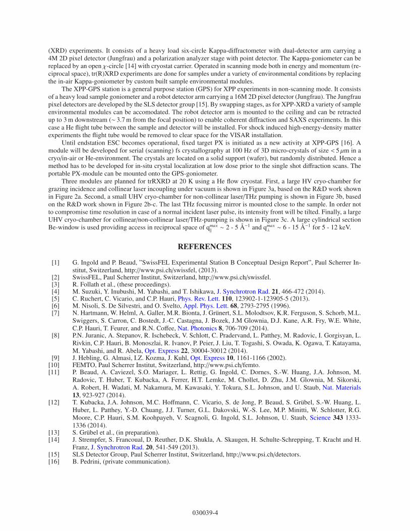
(XRD) experiments. It consists of a heavy load six-circle Kappa-diffractometer with dual-detector arm carrying a4M 2D pixel detector (Jungfrau) and a polarization analyzer stage with point detector. The Kappa-goniometer can bereplaced by an open χ-circle [14] with cryostat carrier. Operated in scanning mode both in energy and momentum (re-ciprocal space), tr(R)XRD experiments are done for samples under a variety of environmental conditions by replacingthe in-air Kappa-goniometer by custom built sample environmental modules.
The XPP-GPS station is a general purpose station (GPS) for XPP experiments in non-scanning mode. It consistsof a heavy load sample goniometer and a robot detector arm carrying a 16M 2D pixel detector (Jungfrau). The Jungfraupixel detectors are developed by the SLS detector group [15]. By swapping stages, as for XPP-XRD a variety of sampleenvironmental modules can be accomodated. The robot detector arm is mounted to the ceiling and can be retractedup to 3 m downstream (∼ 3.7 m from the focal position) to enable coherent diffraction and SAXS experiments. In thiscase a He flight tube between the sample and detector will be installed. For shock induced high-energy-density matterexperiments the flight tube would be removed to clear space for the VISAR installation.
Until endstation ESC becomes operational, fixed target PX is initiated as a new activity at XPP-GPS [16]. Amodule will be developed for serial (scanning) fs crystallography at 100 Hz of 3D micro-crystals of size < 5 μm in acryo/in-air or He-environment. The crystals are located on a solid support (wafer), but randomly distributed. Hence amethod has to be developed for in-situ crystal localization at low dose prior to the single shot diffraction scans. Theportable PX-module can be mounted onto the GPS-goniometer.
Three modules are planned for trRXRD at 20 K using a He flow cryostat. First, a large HV cryo-chamber forgrazing incidence and collinear laser incoupling under vacuum is shown in Figure 3a, based on the R&D work shownin Figure 2a. Second, a small UHV cryo-chamber for non-collinear laser/THz pumping is shown in Figure 3b, basedon the R&D work shown in Figure 2b-c. The last THz focussing mirror is mounted close to the sample. In order notto compromise time resolution in case of a normal incident laser pulse, its intensity front will be tilted. Finally, a largeUHV cryo-chamber for collinear/non-collinear laser/THz-pumping is shown in Figure 3c. A large cylindrical sectionBe-window is used providing access in reciprocal space of qmax
‖ ∼ 2 - 5 Å−1 and qmax⊥ ∼ 6 - 15 Å−1 for 5 - 12 keV.
REFERENCES
[1] G. Ingold and P. Beaud, ”SwissFEL Experimental Station B Conceptual Design Report”, Paul Scherrer In-stitut, Switzerland, http://www.psi.ch/swissfel, (2013).
[2] SwissFEL, Paul Scherrer Institut, Switzerland, http://www.psi.ch/swissfel.[3] R. Follath et al., (these proceedings).[4] M. Suzuki, Y. Inubushi, M. Yabashi, and T. Ishikawa, J. Synchrotron Rad. 21, 466-472 (2014).[5] C. Ruchert, C. Vicario, and C.P. Hauri, Phys. Rev. Lett. 110, 123902-1-123905-5 (2013).[6] M. Nisoli, S. De Silvestri, and O. Svelto, Appl. Phys. Lett. 68, 2793-2795 (1996).[7] N. Hartmann, W. Helml, A. Galler, M.R. Bionta, J. Grunert, S.L. Molodtsov, K.R. Ferguson, S. Schorb, M.L.
Swiggers, S. Carron, C. Bostedt, J.-C. Castagna, J. Bozek, J.M Glownia, D.J. Kane, A.R. Fry, W.E. White,C.P. Hauri, T. Feurer, and R.N. Coffee, Nat. Photonics 8, 706-709 (2014).
[8] P.N. Juranic, A. Stepanov, R. Ischebeck, V. Schlott, C. Pradervand, L. Patthey, M. Radovic, I. Gorgisyan, L.Rivkin, C.P. Hauri, B. Monoszlai, R. Ivanov, P. Peier, J. Liu, T. Togashi, S. Owada, K. Ogawa, T. Katayama,M. Yabashi, and R. Abela, Opt. Express 22, 30004-30012 (2014).
[9] J. Hebling, G. Almasi, I.Z. Kozma, J. Kuhl, Opt. Express 10, 1161-1166 (2002).[10] FEMTO, Paul Scherrer Institut, Switzerland, http://www.psi.ch/femto.[11] P. Beaud, A. Caviezel, S.O. Mariager, L. Rettig, G. Ingold, C. Dornes, S.-W. Huang, J.A. Johnson, M.
Radovic, T. Huber, T. Kubacka, A. Ferrer, H.T. Lemke, M. Chollet, D. Zhu, J.M. Glownia, M. Sikorski,A. Robert, H. Wadati, M. Nakamura, M. Kawasaki, Y. Tokura, S.L. Johnson, and U. Staub, Nat. Materials13, 923-927 (2014).
[12] T. Kubacka, J.A. Johnson, M.C. Hoffmann, C. Vicario, S. de Jong, P. Beaud, S. Grubel, S.-W. Huang, L.Huber, L. Patthey, Y.-D. Chuang, J.J. Turner, G.L. Dakovski, W.-S. Lee, M.P. Minitti, W. Schlotter, R.G.Moore, C.P. Hauri, S.M. Koohpayeh, V. Scagnoli, G. Ingold, S.L. Johnson, U. Staub, Science 343 1333-1336 (2014).
[13] S. Grubel et al., (in preparation).[14] J. Strempfer, S. Francoual, D. Reuther, D.K. Shukla, A. Skaugen, H. Schulte-Schrepping, T. Kracht and H.
Franz, J. Synchrotron Rad. 20, 541-549 (2013).[15] SLS Detector Group, Paul Scherrer Institut, Switzerland, http://www.psi.ch/detectors.[16] B. Pedrini, (private communication).
030039-4