Embed Size (px)
Citation preview
AACC
CCEE
SSSS
IIBBLL
EE LL
IIVVIINN
GG
safe
Home Automation Technologyfor Easy, Safe, and Accessible Living
SOLUTIONSSIMPLE
Funded by the National Institute on Disability and Rehabilitation Researchof the United States Department of Education under grant #H133E40003
Written by
Jeffrey Jerome, BSEE, MBA
Produced by
The Center for Universal DesignSchool of DesignNorth Carolina State University
Disclaimer
This publication was prepared and distributed under a grant from the US Department of Education, National Institute on Disability and RehabilitationResearch (NIDRR). The information provided in this publication is from The Center for Universal Design and does not necessarily reflect the view of the above listed grant funding agency. The recommendations and suggestionscontained within this publication are made without consideration of applicablefederal, state or local regulations.
Credits
Author: Jeffrey Jerome
Technical Assistance: Ronald L. Mace, FAIA
Editor: June Spence
Graphic Design: Robert Rock
Illustration: David Ringholz, Rex Pace, Mark Pace
© 1998 THE CENTER FOR UNIVERSAL DESIGN
ISBN #1-880063-22-0
The Center for Universal DesignSchool of DesignNorth Carolina State UniversityBox 8613Raleigh, NC 27695-8613
(919) 515-3082http://www.design.ncsu.edu/cud
Acknowledgments
Special thanks to the following reviewers who also helped with the productionof this book: Jan Reagan, Larry Trachtman, and Leslie Young.
INTRODUCTION
SIMPLE SOLUTIONS
Remote-Controlled Lighting
Audible and Visible Options for Doorbells
Motion-Activated Room Lighting
In-House Call Chimes
Help Call Pendants
The Garbage Disposal Safety Switch
Stove Timer Safety Switch
Wireless Headphones
Wireless TV Observation Systems
In-House Telephone/Intercom Systems
Voice-Controlled Telephone Systems
Electronic Alternatives to Keys
APPENDICES
Appendix A: Remote-Controlled Lighting and Appliance Control through Power Line Carrier (PLC) Technology
Appendix B: Where To Buy the Equipment
Appendix C: Where To Find Home Systems Installers
Table of Contents
1
2
3
4
5
6
7
8
9
10
11
12
1
5
9
13
17
21
23
27
31
35
39
45
A1
B1
C1
TH
E C
EN
TE
R F
OR
UN
IVE
RS
AL D
ES
IGN
i
Introduction
Welcome to Simple Solutions: Home Automation Technology for Easy, Safe, and Accessible Living. This book describes how relatively inexpensive home technology can benefit everyone–including people with disabilities, busy profes-sionals, older adults, and parents of small children. Many devices and systems are available to make our lives safer, more convenient, and more productive. With so much technology, it is difficult to know what is available and how it can be usedto make living simpler and easier for everyone. That’s where this book can help.
While technology is getting more sophisticated every day, it is also getting easier touse and less expensive. Many of the systems described in this book can be easily installed by the homeowner, and most of them cost less than $100 in parts. Each of the chapters provides all the information needed to determine what the equip-ment can do, how to operate it, and what is required for installation. Appendices provide further details on component selection and installation (Appendix A), offer places to purchase the equipment (Appendix B), and list professional installers (Appendix C). So relax; these systems can make the user’s life much more independentand fulfilling–and an engineering degree isn’t needed to operate them.
This book was produced by The Center for Universal Design, part of the School of Design at North Carolina State University. The Center receives major funding from the U.S. Department of Education’s National Institute on Disability and Rehabilitation Research (NIDRR). As part of this program, the Center conducted a conference called “Emerging Technologies for Independent Living” in November 1994. This conference brought together consumers of various abilities and leading technologists to determine how technology could best assist people to live more independently. The conference participants determined that the greatest barrier to the adoption of home automation was not technology, but the lack of consumer awareness of technology’s benefits. This book was conceived as one method of making people aware of home automation solutions to many common problems.
About the Author
Jeffrey Jerome has been involved in the home automation industry since its incep-tion in the early 1970s with the Smart House project. His background includes a degree in electronic/biomedical engineering and substantial experience in product design for people with disabilities. Mr. Jerome was the designer and director of Future Home–the nation’s first demonstration of how home automation can facilitateindependent living for people with disabilities and older adults. He has been involved in the electronics systems design of dozens of homes, many of them for people with disabilities.

SOLUTIONS
Remote-Controlled Lighting
Turning the lights on and off from anywhere in the home
Audible and Visible Options for Doorbells
Knowing someone is at the door when you can’t hear the doorbell
Motion-Activated Room Lighting
Turning on lights without using your hands
In-House Call Chimes
Alerting others in the home or nearby that you need their help
Help Call Pendants
Calling for outside help if you can’t reach a telephone
The Garbage Disposal Safety Switch
Preventing garbage disposal accidents
Stove Timer Safety Switch
Ensuring that the stove doesn’t start a fire if someone forgets to turn it off
Wireless Headphones
Turning up the volume without disturbing others
Wireless TV Observation Systems
Keeping an eye on someone in another room
In-House Telephone/Intercom Systems
Communicating with others inside and outside the home
Voice-Controlled Telephone Systems
Making telephone calls without pressing keys
Electronic Alternatives to Keys
Unlocking the door without a key
1
2
3
4
5
6
7
8
9
10
11
12
SIMPLE
TH
E C
EN
TE
R F
OR
UN
IVE
RS
AL D
ES
IGN
1
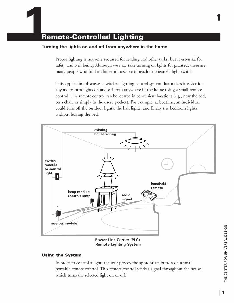
Remote-Controlled LightingTurning the lights on and off from anywhere in the home
Proper lighting is not only required for reading and other tasks, but is essential for safety and well being. Although we may take turning on lights for granted, there aremany people who find it almost impossible to reach or operate a light switch.
This application discusses a wireless lighting control system that makes it easier for anyone to turn lights on and off from anywhere in the home using a small remote control. The remote control can be located in convenient locations (e.g., near the bed,on a chair, or simply in the user’s pocket). For example, at bedtime, an individual could turn off the outdoor lights, the hall lights, and finally the bedroom lights without leaving the bed.
Using the System
In order to control a light, the user presses the appropriate button on a small portable remote control. This remote control sends a signal throughout the house which turns the selected light on or off.
Power Line Carrier (PLC)
Remote Lighting System
1
switch
module
to control
light
existing
house wiring
lamp module
controls lamp
receiver module
radio
signal
handheld
remote
1
TH
E C
EN
TE
R F
OR
UN
IVE
RS
AL D
ES
IGN
2
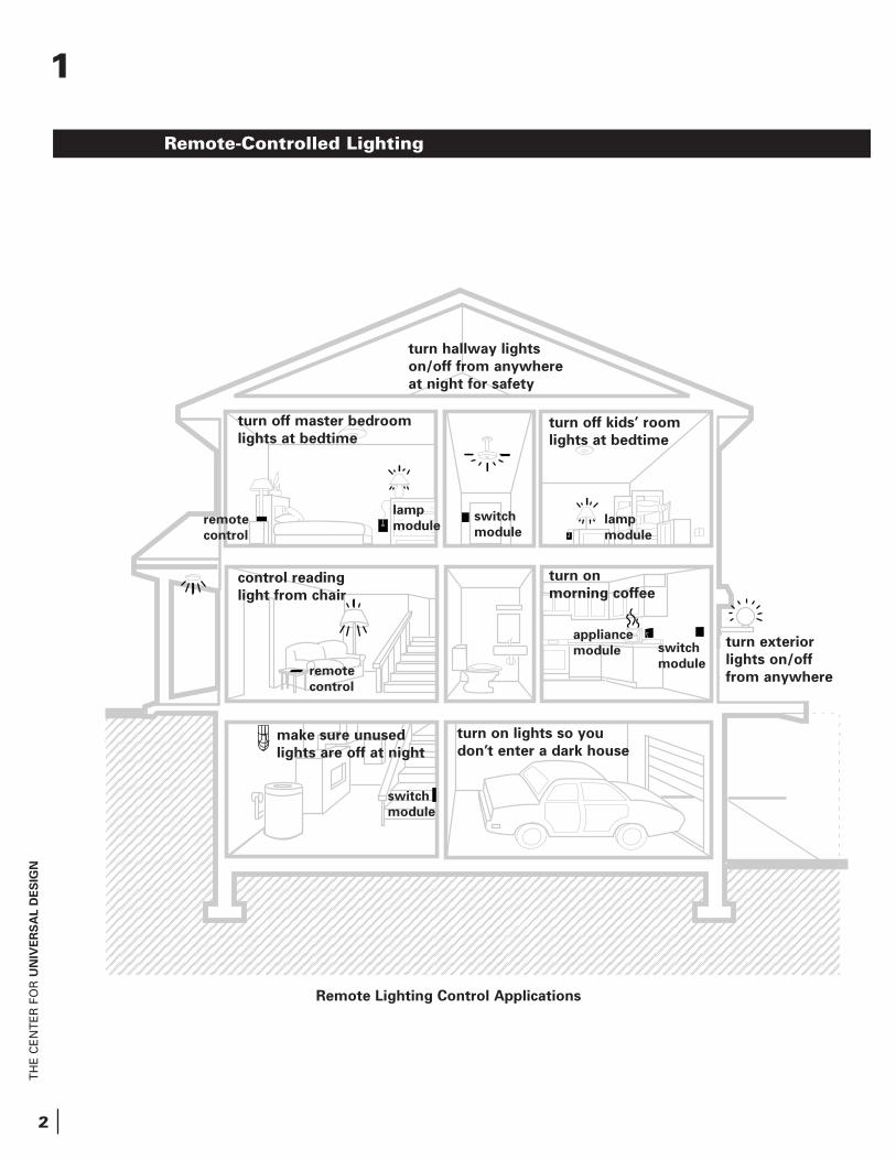
Remote Lighting Control Applications
remote
control
switch
module
lamp
modulelamp
module
remote
control
switch
module
switch
module
appliance
module
turn off master bedroom
lights at bedtime
turn hallway lights
on/off from anywhere
at night for safety
turn off kids’ room
lights at bedtime
turn on
morning coffeecontrol reading
light from chair
make sure unused
lights are off at night
turn on lights so you
don’t enter a dark house
Remote-Controlled Lighting
1
turn exterior
lights on/off
from anywhere
TH
E C
EN
TE
R F
OR
UN
IVE
RS
AL D
ES
IGN
3
How the System Works
The system uses Power Line Carrier (PLC) lighting control equipment, which consists of inexpensive wireless remote controls, lamp modules, and switch modules. The remote control transmitter sends out radio signal commands when its buttons are pressed. The command signals are coded to specify which light to control and whether to have it turn on, turn off, brighten, or dim the light. These radio signals are received by a plug-in receiver module which retransmits them through the home’s existing power lines. Each lamp or switch module has a user selectable address code (1-16) which allows the user to specify exactly which light is to be controlled by any given coded signal. Each module listens to each signal, but only responds to commands with its particular address. Once a module recognizes that the command is for its own address, it makes its light/appliance turn on or off, or brighten or dim accordingly. Because the system uses signals that run along the existing electrical wiring, no new wires are needed.
What to Buy
PLC controls and modules are inexpensive and readily available in electronics stores such as Radio Shack and some hardware and specialty shops. Although there are many types of PLC transmitters, two of the most appropriate are described below:
sThe Handheld Remote Control (Leviton 6313 and 6314 or X-10 RT 504 or equivalent), about the size of a cigarette pack, can turn on, turn off, brighten, and dim up to two independent sets of eight independently controllable lights. The X-10 version of this comes with receiver and transmitter; however, the receiver is sold separately for the Leviton version (part no. 6314). These remotes and receivers cost between $25 and $75 retail.
sPeople with limited coordination might want to consider a Surface
Mounted Remote Control (X-10 part nos. RW 684 and RW 6900), which has fewer, but larger, buttons than the Handheld Remote Control.
Lamp and switch modules control individual lights in response to signals sent by any PLC transmitter. Plug-in modules come as lamp modules (used only for lamps of under 500 watts) as well as non-dimming modules which can be used for lamps or small appliances. Switch modules are used where the lights are controlled by in-wall electrical switches. These modules replace the existing switches and come in various types. See Appendix A for assistance on selecting lamp and switch modules.
Remote-Controlled Lighting
1
TH
E C
EN
TE
R F
OR
UN
IVE
RS
AL D
ES
IGN
4
Installing the System
Transmitter, receiver, lamp, and appliance modules can be easily installed by almost anyone using only a small screwdriver. It is, however, very important to select the transmitters that are easily accessible by the user. Plug-in lamp/appliance modules are used to control devices that plug into a wall outlet. These are also veryeasy to install via the process described in Appendix A.
Switch modules are used to control lights that use a wall switch. Switch modules replace the existing wall switches and may be installed by homeowners, as local building codes allow, if they are familiar with electrical switches. Caution should beexercised as high voltages exist in the switch boxes, and the power must be turned off at the appropriate circuit breaker before attempting to change the switch. See Appendix A for more details on this installation.
Remote-Controlled Lighting
1
TH
E C
EN
TE
R F
OR
UN
IVE
RS
AL D
ES
IGN
5
Audible and Visible Options for DoorbellsKnowing that someone is at the door when you can’t hear the doorbell
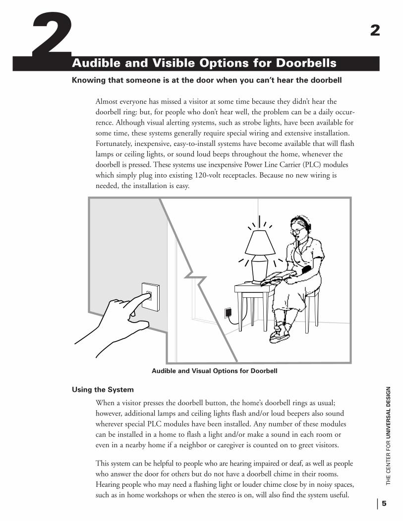
Almost everyone has missed a visitor at some time because they didn’t hear the doorbell ring: but, for people who don’t hear well, the problem can be a daily occur-rence. Although visual alerting systems, such as strobe lights, have been available forsome time, these systems generally require special wiring and extensive installation. Fortunately, inexpensive, easy-to-install systems have become available that will flashlamps or ceiling lights, or sound loud beeps throughout the home, whenever the doorbell is pressed. These systems use inexpensive Power Line Carrier (PLC) moduleswhich simply plug into existing 120-volt receptacles. Because no new wiring is needed, the installation is easy.
Using the System
When a visitor presses the doorbell button, the home’s doorbell rings as usual; however, additional lamps and ceiling lights flash and/or loud beepers also sound wherever special PLC modules have been installed. Any number of these modules can be installed in a home to flash a light and/or make a sound in each room or even in a nearby home if a neighbor or caregiver is counted on to greet visitors.
This system can be helpful to people who are hearing impaired or deaf, as well as people who answer the door for others but do not have a doorbell chime in their rooms. Hearing people who may need a flashing light or louder chime close by in noisy spaces,such as in home workshops or when the stereo is on, will also find the system useful.
2
Audible and Visual Options for Doorbell
2
TH
E C
EN
TE
R F
OR
UN
IVE
RS
AL D
ES
IGN
6
How the System Works
A special transmitter called a Powerflash Module is connected via a wire to the doorbell terminals in the existing chime and then plugged into a convenient outlet. When the doorbell button is pressed, the Powerflash Module sends a “flash” signal out over the home’s existing electrical wiring. This signal causes any PLC receiver modules connected to the power line to flash on and off while the doorbell button is pressed.
The lamp designated to flash is plugged into a PLC receiver module, which can be plugged into any electrical outlet. For a ceiling light to flash, a switch module must replace the wall switch that currently controls the light. In either case, these modulesreceive the flash signal from the Powerflash Module and cause the associated light toflash while the doorbell is pressed. Sounder modules plugged into receptacles also receive this signal and produce an audible tone.
What to Buy
All of the parts for this system are readily available and relatively inexpensive. You will need:
s Powerflash Module: (X-10 part no. PF284)
s 22 gauge (or larger) two-conductor wire, long enough to run from the existing doorbell to the Powerflash Module (which is plugged into a nearby 120-volt electrical outlet)
s One plug-in lamp module for each lamp to flash
s One switch module for each light controlled by a wall switch to flash
s Sounder modules to produce loud sounds (X-10 part no. SC546)
Audible and Visible Options for Doorbells
2
TH
E C
EN
TE
R F
OR
UN
IVE
RS
AL D
ES
IGN
7
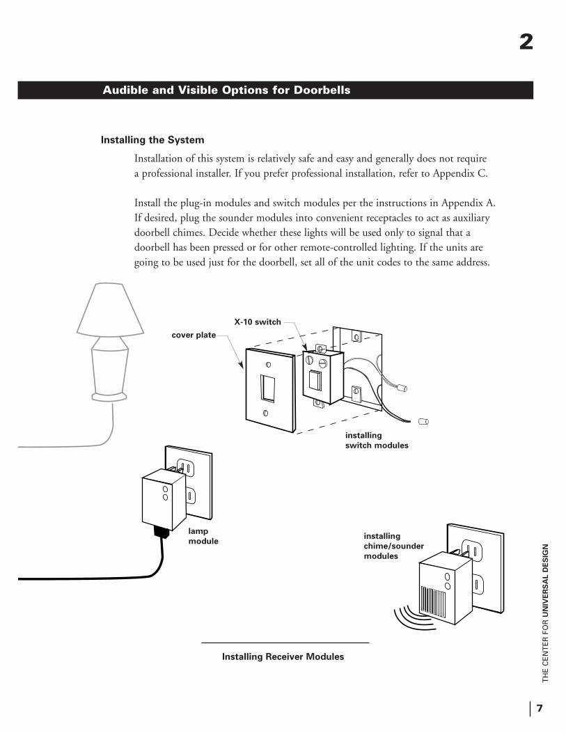
Installing the System
Installation of this system is relatively safe and easy and generally does not require a professional installer. If you prefer professional installation, refer to Appendix C.
Install the plug-in modules and switch modules per the instructions in Appendix A. If desired, plug the sounder modules into convenient receptacles to act as auxiliary doorbell chimes. Decide whether these lights will be used only to signal that a doorbell has been pressed or for other remote-controlled lighting. If the units are going to be used just for the doorbell, set all of the unit codes to the same address.
Installing Receiver Modules
Audible and Visible Options for Doorbells
cover plate
X-10 switch
installing
switch modules
installing
chime/sounder
modules
lamp
module
2
TH
E C
EN
TE
R F
OR
UN
IVE
RS
AL D
ES
IGN
8
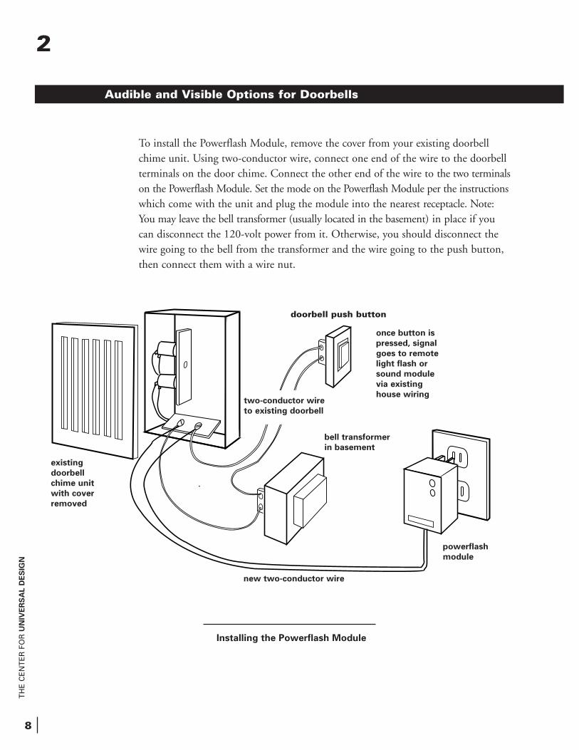
Installing the Powerflash Module
To install the Powerflash Module, remove the cover from your existing doorbell chime unit. Using two-conductor wire, connect one end of the wire to the doorbell terminals on the door chime. Connect the other end of the wire to the two terminalson the Powerflash Module. Set the mode on the Powerflash Module per the instructionswhich come with the unit and plug the module into the nearest receptacle. Note: You may leave the bell transformer (usually located in the basement) in place if you can disconnect the 120-volt power from it. Otherwise, you should disconnect the wire going to the bell from the transformer and the wire going to the push button, then connect them with a wire nut.
Audible and Visible Options for Doorbells
powerflash
module
new two-conductor wire
bell transformer
in basement
two-conductor wire
to existing doorbell
existing
doorbell
chime unit
with cover
removed
once button is
pressed, signal
goes to remote
light flash or
sound module
via existing
house wiring
2
doorbell push button
TH
E C
EN
TE
R F
OR
UN
IVE
RS
AL D
ES
IGN
9
3Motion-Activated Room LightingTurning on lights without using your hands
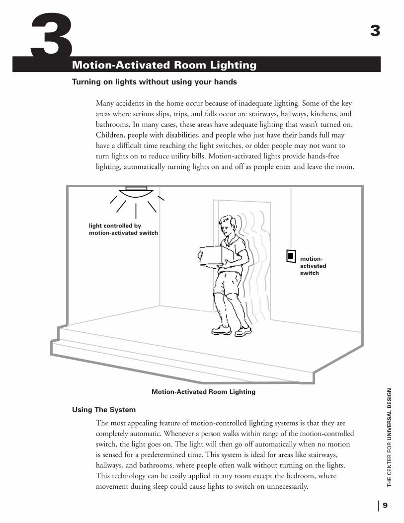
Many accidents in the home occur because of inadequate lighting. Some of the key areas where serious slips, trips, and falls occur are stairways, hallways, kitchens, and bathrooms. In many cases, these areas have adequate lighting that wasn’t turned on. Children, people with disabilities, and people who just have their hands full may have a difficult time reaching the light switches, or older people may not want to turn lights on to reduce utility bills. Motion-activated lights provide hands-free lighting, automatically turning lights on and off as people enter and leave the room.
Using The System
The most appealing feature of motion-controlled lighting systems is that they are completely automatic. Whenever a person walks within range of the motion-controlledswitch, the light goes on. The light will then go off automatically when no motion is sensed for a predetermined time. This system is ideal for areas like stairways, hallways, and bathrooms, where people often walk without turning on the lights. This technology can be easily applied to any room except the bedroom, where movement during sleep could cause lights to switch on unnecessarily.
Motion-Activated Room Lighting
light controlled by
motion-activated switch
motion-
activated
switch
3
TH
E C
EN
TE
R F
OR
UN
IVE
RS
AL D
ES
IGN
10
How the System Works
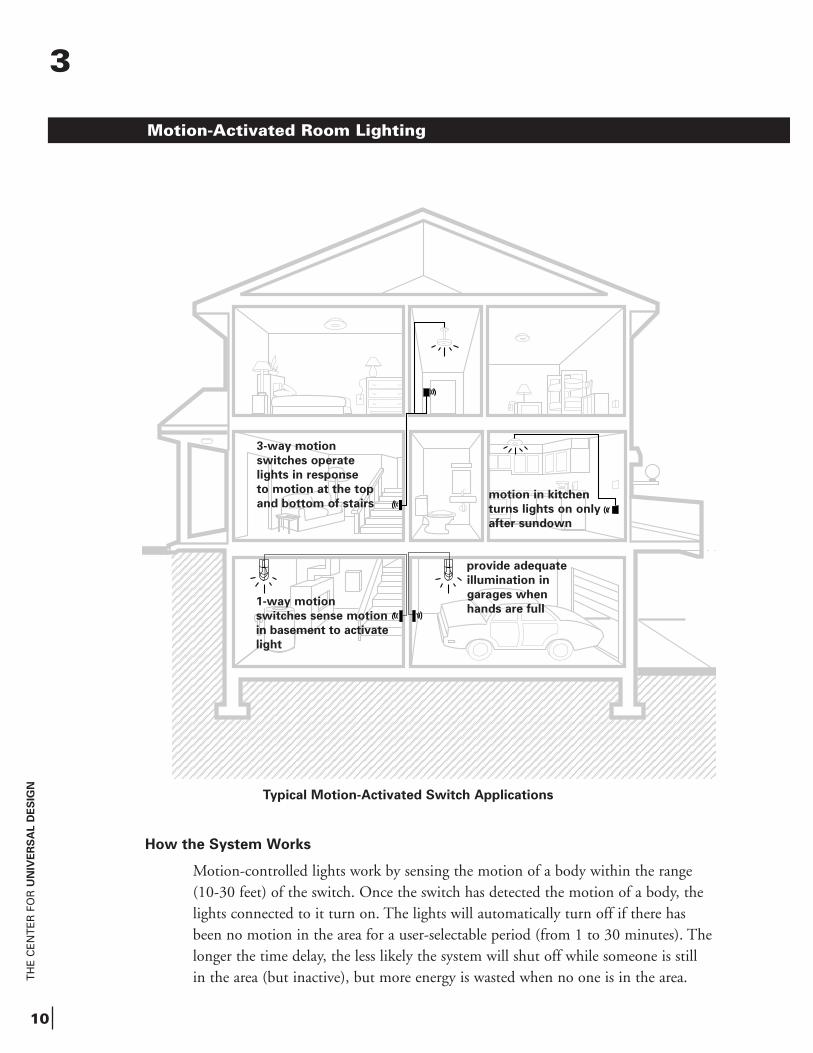
Motion-controlled lights work by sensing the motion of a body within the range (10-30 feet) of the switch. Once the switch has detected the motion of a body, the lights connected to it turn on. The lights will automatically turn off if there has been no motion in the area for a user-selectable period (from 1 to 30 minutes). The longer the time delay, the less likely the system will shut off while someone is still in the area (but inactive), but more energy is wasted when no one is in the area.
Typical Motion-Activated Switch Applications
Motion-Activated Room Lighting
3-way motion
switches operate
lights in response
to motion at the top
and bottom of stairsmotion in kitchen
turns lights on only
after sundown
1-way motion
switches sense motion
in basement to activate
light
provide adequate
illumination in
garages when
hands are full
3
TH
E C
EN
TE
R F
OR
UN
IVE
RS
AL D
ES
IGN
11
What To Buy
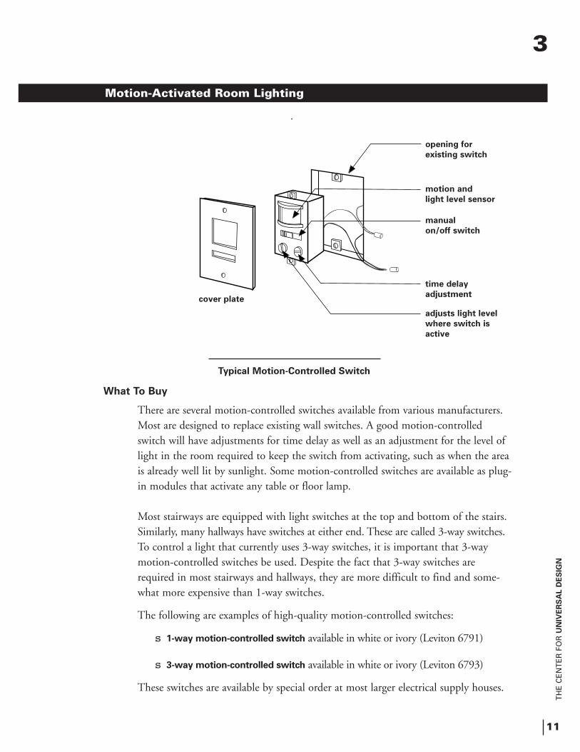
There are several motion-controlled switches available from various manufacturers. Most are designed to replace existing wall switches. A good motion-controlled switch will have adjustments for time delay as well as an adjustment for the level of light in the room required to keep the switch from activating, such as when the areais already well lit by sunlight. Some motion-controlled switches are available as plug-in modules that activate any table or floor lamp.
Most stairways are equipped with light switches at the top and bottom of the stairs. Similarly, many hallways have switches at either end. These are called 3-way switches.To control a light that currently uses 3-way switches, it is important that 3-way motion-controlled switches be used. Despite the fact that 3-way switches are required in most stairways and hallways, they are more difficult to find and some-what more expensive than 1-way switches.
The following are examples of high-quality motion-controlled switches:
s 1-way motion-controlled switch available in white or ivory (Leviton 6791)
s 3-way motion-controlled switch available in white or ivory (Leviton 6793)
These switches are available by special order at most larger electrical supply houses.
Typical Motion-Controlled Switch
Motion-Activated Room Lighting
opening for
existing switch
motion and
light level sensor
manual
on/off switch
time delay
adjustment
adjusts light level
where switch is
active
cover plate
3
TH
E C
EN
TE
R F
OR
UN
IVE
RS
AL D
ES
IGN
12
Installing the System
Simply remove the existing light switch (or switches for 3-way applications) and replace with the motion-controlled switch(es). During the initial installation, the installer needs to set simple screwdriver adjustments for lighting level and delay time. The lighting level setting determines how dark it needs to be before the switchwill turn the lights on when motion is sensed. The delay time determines how long the light will stay on after the last motion is detected.
These switches can be installed by the homeowner if local building codes allow, if the homeowner feels comfortable with changing 1- and 3-way switches, and if the homeowner takes appropriate precautions against accidental electrical shock. If professional installation is preferred, any licensed electrician should be able to installthese devices.
Motion-Activated Room Lighting
3
TH
E C
EN
TE
R F
OR
UN
IVE
RS
AL D
ES
IGN
13
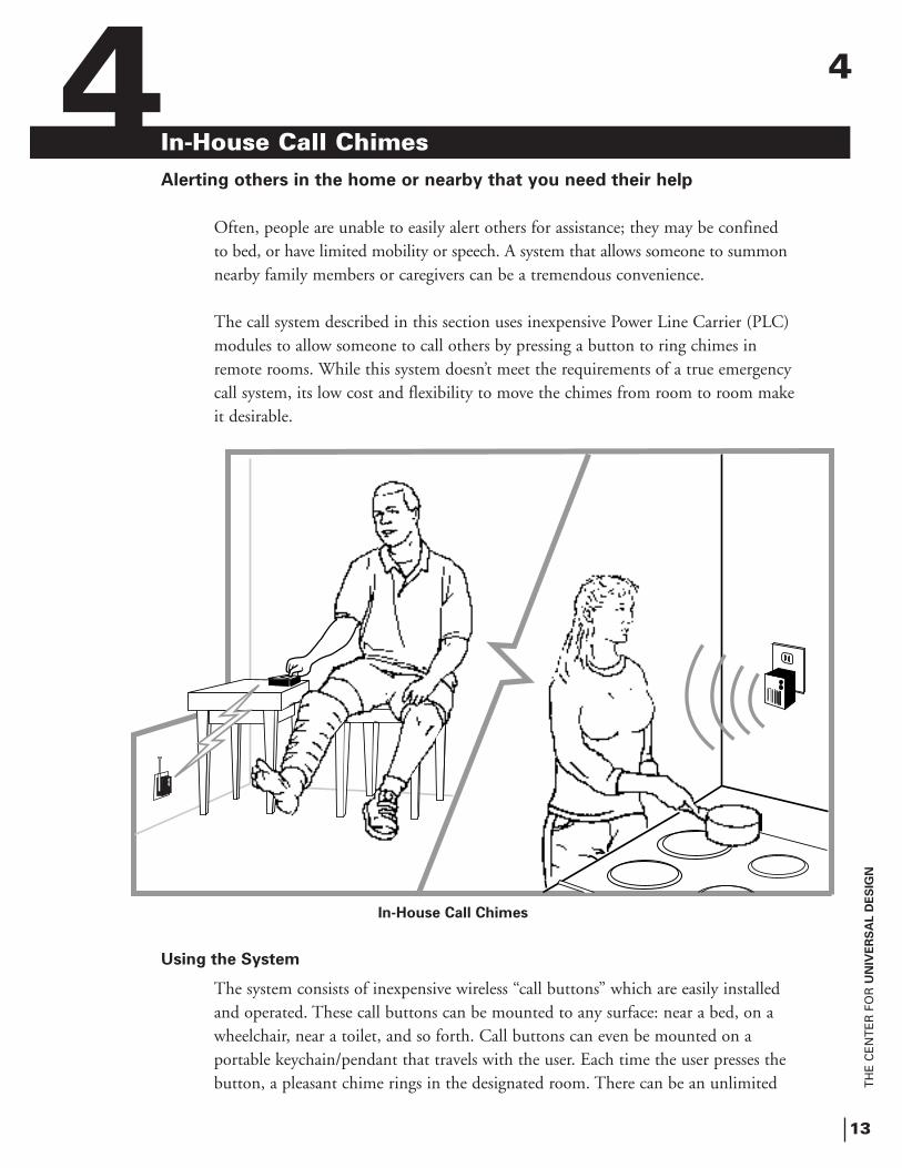
In-House Call Chimes Alerting others in the home or nearby that you need their help
Often, people are unable to easily alert others for assistance; they may be confined to bed, or have limited mobility or speech. A system that allows someone to summonnearby family members or caregivers can be a tremendous convenience.
The call system described in this section uses inexpensive Power Line Carrier (PLC) modules to allow someone to call others by pressing a button to ring chimes in remote rooms. While this system doesn’t meet the requirements of a true emergencycall system, its low cost and flexibility to move the chimes from room to room makeit desirable.
Using the System
The system consists of inexpensive wireless “call buttons” which are easily installed and operated. These call buttons can be mounted to any surface: near a bed, on a wheelchair, near a toilet, and so forth. Call buttons can even be mounted on a portable keychain/pendant that travels with the user. Each time the user presses the button, a pleasant chime rings in the designated room. There can be an unlimited
In-House Call Chimes
4 4
TH
E C
EN
TE
R F
OR
UN
IVE
RS
AL D
ES
IGN
14
number of chimes in various rooms of the home and often in nearby apart-ments and homes as well. These products are usually reliable, but because of potential failure they must never be relied upon as the only alert system for emergency or life threatening situations.
How the System Works
The remote control transmitters are devices that send out commands via radio signals when their buttons are pressed. These radio signals are received by a plug-in receiver module and then transmitted through the home’s existingpower lines. Chime Modules, which are plugged into the standard 120 VACoutlets in any room, ring each time the user presses the transmitter button. Because the system uses radio waves, no new wires are needed.
What to Buy
You will need at least one transmitter module, one receiver module and one chime module. All parts are made by X-10 USA.
s Transmitter/Receiver Kits (1 required)s Wireless Wall Switch Remote Control System Kit
(transmitter and receiver) - (X-10 part no. RW6900) s Wireless Keychain Remote System Kit
(transmitter and receiver) - (X-10 part no. RC6500)
s Chime Modules - (X-10 part no. SC546)
s Optional Additional Transmitters
s 4 Unit Wireless Wall Switch Transmitter (X-10 part no. RW694)s 2 Unit Wireless Wall Switch Transmitter (X-10 part no. RW684)
In-House Call Chimes
4
TH
E C
EN
TE
R F
OR
UN
IVE
RS
AL D
ES
IGN
15
on
off
X10 powerhouse
1
2
3
45
Remote Call Chime System
In-House Call Chimes
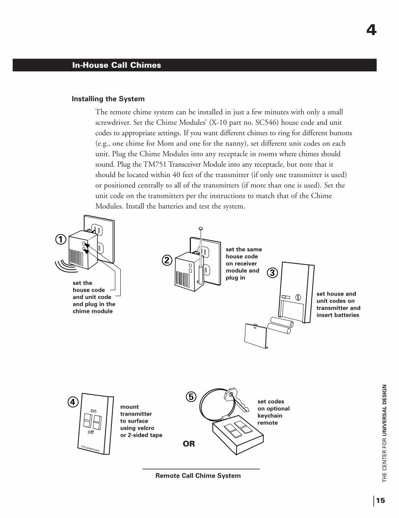
Installing the System
The remote chime system can be installed in just a few minutes with only a small screwdriver. Set the Chime Modules’ (X-10 part no. SC546) house code and unit codes to appropriate settings. If you want different chimes to ring for different buttons(e.g., one chime for Mom and one for the nanny), set different unit codes on each unit. Plug the Chime Modules into any receptacle in rooms where chimes should sound. Plug the TM751 Transceiver Module into any receptacle, but note that it should be located within 40 feet of the transmitter (if only one transmitter is used) or positioned centrally to all of the transmitters (if more than one is used). Set the unit code on the transmitters per the instructions to match that of the Chime Modules. Install the batteries and test the system.
set the
house code
and unit code
and plug in the
chime module
set the same
house code
on receiver
module and
plug in
set house and
unit codes on
transmitter and
insert batteries
mount
transmitter
to surface
using velcro
or 2-sided tape
set codes
on optional
keychain
remote
4
OR

TH
E C
EN
TE
R F
OR
UN
IVE
RS
AL D
ES
IGN
In-House Call Chimes

TH
E C
EN
TE
R F
OR
UN
IVE
RS
AL D
ES
IGN
17
Help Call PendantsCalling for outside help if you can’t reach a telephone
Call pendants serve an important function by providing peace of mind to thousandsof people. Help Call Pendants are typically associated with elderly people living alone; however, they are just as appropriate for people with disabilities or acute illnesses. They can also provide an extra measure of security for “latch-key kids” when they’re home alone.
Using the System
Help Call Pendant Systems allow a person to easily call for help. When there is an emergency, the user presses a button on a small radio transmitter worn around the neck or wrist. When the button is pressed, a neighbor, relative, or a professional monitoring service is notified. At that time, a telephone connection is established with the user’s residence. This phone link allows the person on the other end to communicate with the person who has pressed the button. Depending on the response, the alerted party determines the degree of assistance needed and decides whether or not to dispatch help.
Help Call Phone System
5
user presses
panic button
transmitter
sends signal
when signal
is received,
the help phone
dials and opens
the speaker
phone
person at any
receiving phone
can listen and talk
to homeowner, and
dispatch help if
needed
5
TH
E C
EN
TE
R F
OR
UN
IVE
RS
AL D
ES
IGN
18
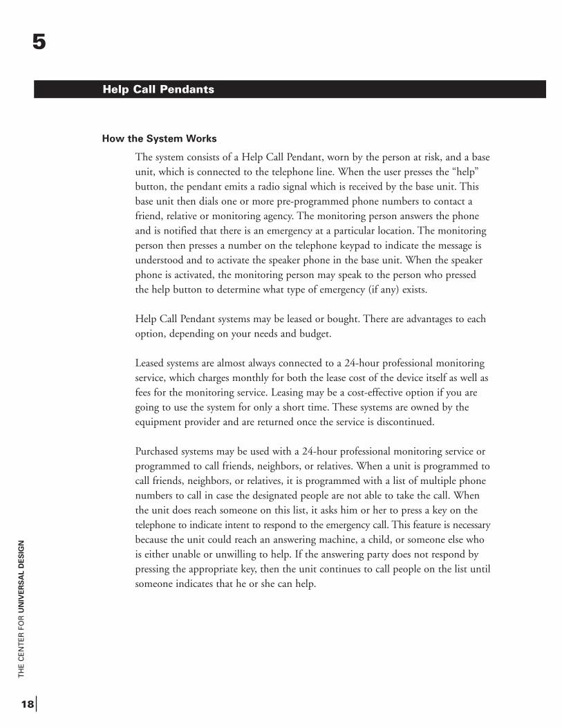
How the System Works
The system consists of a Help Call Pendant, worn by the person at risk, and a base unit, which is connected to the telephone line. When the user presses the “help” button, the pendant emits a radio signal which is received by the base unit. This base unit then dials one or more pre-programmed phone numbers to contact a friend, relative or monitoring agency. The monitoring person answers the phone and is notified that there is an emergency at a particular location. The monitoring person then presses a number on the telephone keypad to indicate the message is understood and to activate the speaker phone in the base unit. When the speaker phone is activated, the monitoring person may speak to the person who pressed the help button to determine what type of emergency (if any) exists.
Help Call Pendant systems may be leased or bought. There are advantages to each option, depending on your needs and budget.
Leased systems are almost always connected to a 24-hour professional monitoring service, which charges monthly for both the lease cost of the device itself as well as fees for the monitoring service. Leasing may be a cost-effective option if you are going to use the system for only a short time. These systems are owned by the equipment provider and are returned once the service is discontinued.
Purchased systems may be used with a 24-hour professional monitoring service or programmed to call friends, neighbors, or relatives. When a unit is programmed to call friends, neighbors, or relatives, it is programmed with a list of multiple phone numbers to call in case the designated people are not able to take the call. When the unit does reach someone on this list, it asks him or her to press a key on the telephone to indicate intent to respond to the emergency call. This feature is necessarybecause the unit could reach an answering machine, a child, or someone else who is either unable or unwilling to help. If the answering party does not respond by pressing the appropriate key, then the unit continues to call people on the list until someone indicates that he or she can help.
Help Call Pendants
5
TH
E C
EN
TE
R F
OR
UN
IVE
RS
AL D
ES
IGN
19
What to Buy
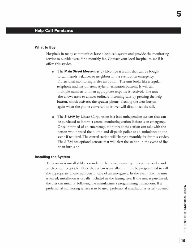
Hospitals in many communities lease a help call system and provide the monitoringservice to outside users for a monthly fee. Contact your local hospital to see if it offers this service.
s The Main Street Messenger by Elcombe is a unit that can be bought to call friends, relatives or neighbors in the event of an emergency. Professional monitoring is also an option. The unit looks like a regular telephone and has different styles of activation buttons. It will call multiple numbers until an appropriate response is received. The unit also allows users to answer ordinary incoming calls by pressing the help button, which activates the speaker phone. Pressing the alert button again when the phone conversation is over will disconnect the call.
s The S-724V by Linear Corporation is a base unit/pendant system that can be purchased to inform a central monitoring station if there is an emergency.Once informed of an emergency, monitors at the station can talk with theperson who pressed the button and dispatch police or an ambulance to the scene if required. The central station will charge a monthly fee for this service.The S-724 has optional sensors that will alert the station in the event of fireor an intrusion.
Installing the System
The system is installed like a standard telephone, requiring a telephone outlet and an electrical receptacle. Once the system is installed, it must be programmed to call the appropriate phone numbers in case of an emergency. In the event that the unit is leased, installation is usually included in the leasing fees. If the unit is purchased, the user can install it, following the manufacturer’s programming instructions. If a professional monitoring service is to be used, professional installation is usually advised.
Help Call Pendants
5

TH
E C
EN
TE
R F
OR
UN
IVE
RS
AL D
ES
IGN
Help Call Pendants
TH
E C
EN
TE
R F
OR
UN
IVE
RS
AL D
ES
IGN
21
The Garbage Disposal Safety SwitchPreventing garbage disposal accidents
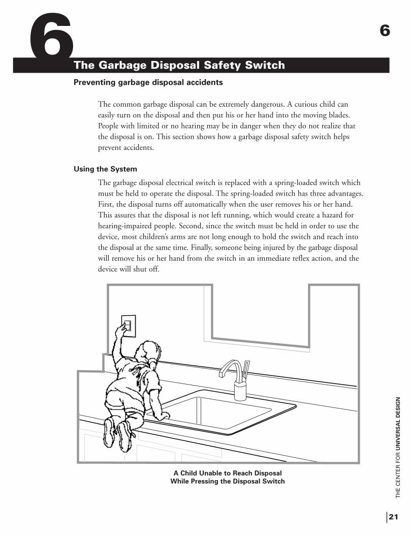
The common garbage disposal can be extremely dangerous. A curious child can easily turn on the disposal and then put his or her hand into the moving blades. People with limited or no hearing may be in danger when they do not realize that the disposal is on. This section shows how a garbage disposal safety switch helps prevent accidents.
Using the System
The garbage disposal electrical switch is replaced with a spring-loaded switch which must be held to operate the disposal. The spring-loaded switch has three advantages.First, the disposal turns off automatically when the user removes his or her hand. This assures that the disposal is not left running, which would create a hazard for hearing-impaired people. Second, since the switch must be held in order to use the device, most children’s arms are not long enough to hold the switch and reach into the disposal at the same time. Finally, someone being injured by the garbage disposalwill remove his or her hand from the switch in an immediate reflex action, and the device will shut off.
A Child Unable to Reach Disposal
While Pressing the Disposal Switch
6 6
TH
E C
EN
TE
R F
OR
UN
IVE
RS
AL D
ES
IGN
22
Occasionally, there are kitchens where the garbage disposal is so far from its switch that it isn’t possible to hold the switch with one hand while feeding food into the disposal with the other. In other cases, people may only have use of one hand, or they may require the use of both hands while the disposal is operating. For these situations, a pilot light switch can be used instead of the spring-loaded switch. Although the pilot light switch lacks the inherent safety advantages of the spring-loaded switch, it does have a built-in light which illuminates to indicate the disposalis on.
What to Buy
The system requires one of the following switches:
s A spring-loaded switch available in a number of colors. (Leviton 5657-2)
s A pilot light switch available in a number of colors. (Leviton 5628)
Leviton switches are available at most electrical supply houses or can be ordered through many of the larger hardware stores. Both of these replacement switches are Decora style, featuring large, easy-to-operate paddle switches. Decora-style switches require corresponding wall plates which are available at most electrical supply housesand hardware stores.
Installing the System
Installation simply involves removing the wall switch controlling the garbage disposal and replacing it with one of the above two switches. For the Leviton 5657-2switch, the wires should be connected to the common terminal and either of the two remaining terminals.
The Garbage Disposal Safety Switch
6
TH
E C
EN
TE
R F
OR
UN
IVE
RS
AL D
ES
IGN
23
Stove Timer Safety SwitchEnsuring that the stove doesn’t start a fire if someone forgets to turn it off
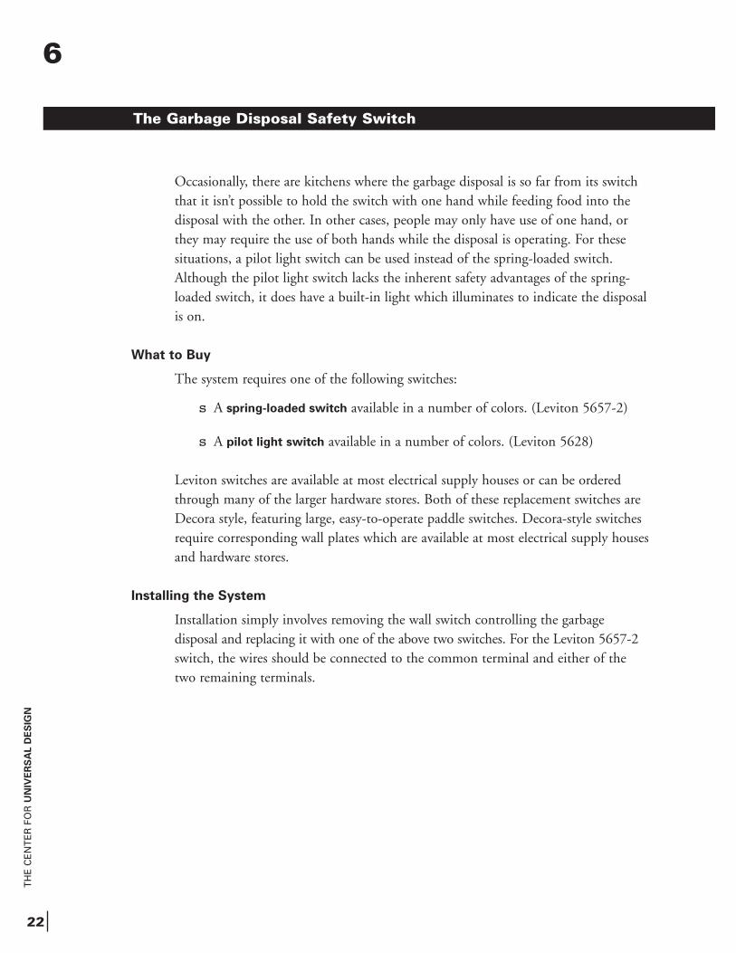
At one time or another, almost everyone forgets about something cooking on the stove. Most of the time, this only results in a ruined meal and a mess, but sometimes it causes a life-threatening fire. People with Alzheimer’s disease or other cognitive impairments may forget to turn off the stove, and their ability to respond appropriately to a fire can be limited, increasing the danger. Fortunately, there are products that will automatically turn off the stove after a preset time or in the eventthat severe overheating occurs. The Range Timer turns off the stove after a predeter-mined time, and the Heatguard is an optional overheat shutoff device.
Using the System
A stove, range, or cooktop equipped with the Range Timer and Heatguard operates the same as before, but it will shut itself off after a preset time or if the stove is severely overheating. The timer can be set from 10 to 90 minutes during installationbut is normally not changed once set.
Units equipped with the Heatguard come with a key that can disable the Range Timer and Heatguard when the safety feature isn’t needed. This key is extremely useful in family situations. For example, the timer may be overridden by Mom and Dad, but it remains functional for Grandma and the kids. Professional attendants who come in to cook for older adults will also find the key useful.
The Problem
7 7
TH
E C
EN
TE
R F
OR
UN
IVE
RS
AL D
ES
IGN
24
How the System Works
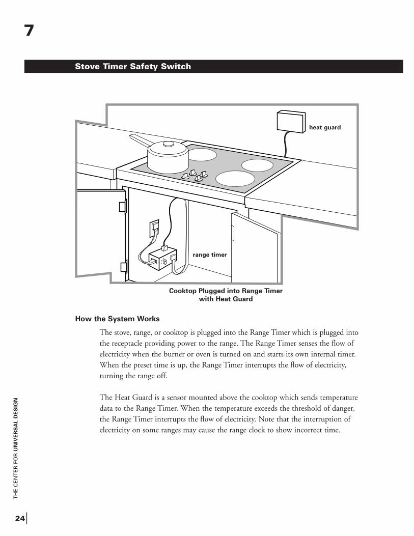
The stove, range, or cooktop is plugged into the Range Timer which is plugged into the receptacle providing power to the range. The Range Timer senses the flow of electricity when the burner or oven is turned on and starts its own internal timer. When the preset time is up, the Range Timer interrupts the flow of electricity, turning the range off.
The Heat Guard is a sensor mounted above the cooktop which sends temperature data to the Range Timer. When the temperature exceeds the threshold of danger, the Range Timer interrupts the flow of electricity. Note that the interruption of electricity on some ranges may cause the range clock to show incorrect time.
Cooktop Plugged into Range Timer
with Heat Guard
Stove Timer Safety Switch
heat guard
range timer
7
TH
E C
EN
TE
R F
OR
UN
IVE
RS
AL D
ES
IGN
25
What to Buy
s The Range Timer and the optional Heat Guard are available from the Logan Powell Company of Camp Hill, PA. See Appendix B for the address and phone number. The prices are approximately $425 and $125, respectively, and a lease program may be available. Note that the Heat Guard needs the Range Timer to operate.
Installing the System
If your stove, range, or cooktop plugs into a receptacle (check behind the stove or under the cooktop to determine this), you can probably install the Range Timer and Heat Guard yourself. Exercise caution: 220 electrical volts are present at the receptacle. If your appliance is “hardwired,” as many are, then an electrician will be required to fit a plug onto the range and a receptacle into the wall. This should costunder $100.
Once a plug and receptacle are available, installation can be accomplished in just a few minutes. Simply plug the Range Timer into the wall receptacle and plug the appliance into the Range Timer. Set the turn-off time on the Range Timer (20 minutesis typical). If a Heat Guard is being used, it is mounted on the wall about 2 feet above the cooking surface. The control wire is run behind the stove to the Range Timer. Remember that the Heat Guard must be connected to the Range Timer to work.
Stove Timer Safety Switch
7

TH
E C
EN
TE
R F
OR
UN
IVE
RS
AL D
ES
IGN
TH
E C
EN
TE
R F
OR
UN
IVE
RS
AL D
ES
IGN
27
Wireless HeadphonesTurning up the volume without disturbing others
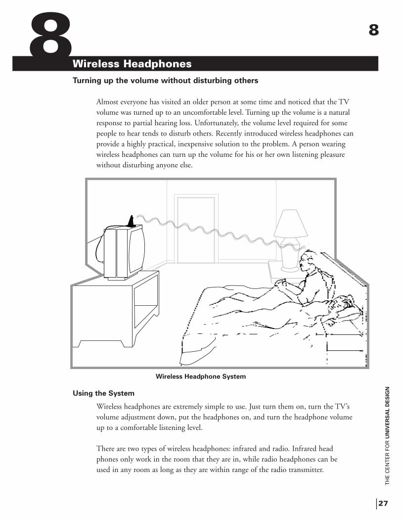
Almost everyone has visited an older person at some time and noticed that the TV volume was turned up to an uncomfortable level. Turning up the volume is a natural response to partial hearing loss. Unfortunately, the volume level required for some people to hear tends to disturb others. Recently introduced wireless headphones canprovide a highly practical, inexpensive solution to the problem. A person wearing wireless headphones can turn up the volume for his or her own listening pleasure without disturbing anyone else.
Using the System
Wireless headphones are extremely simple to use. Just turn them on, turn the TV’svolume adjustment down, put the headphones on, and turn the headphone volumeup to a comfortable listening level.
There are two types of wireless headphones: infrared and radio. Infrared headphones only work in the room that they are in, while radio headphones can be used in any room as long as they are within range of the radio transmitter.
Wireless Headphone System
8 8
TH
E C
EN
TE
R F
OR
UN
IVE
RS
AL D
ES
IGN
28
How the System Works
Wireless headphones take the electrical signal which creates the sound from the television and convert it to infrared light or radio waves. These signals are emitted by the headphone transmitter throughout the room (infrared style) or the entire home (radio style). The headphones worn by the user receive and amplify the signal to produce sound from the small speakers in the earpieces of the headphones.
Because headphone speakers are worn very close to the ears, the actual volume level is much lower than the television’s speaker that sends sound throughout the entire room, reducing noise. Rechargeable or replaceable batteries provide electricity to the headphones.
What to Buy
There are dozens of wireless headphones on the market that may be purchased at practically any store that carries electronics. Before purchasing this product, it is important to be aware of the differences between infrared and radio styles of wireless headphones.
s Infrared headphones can have excellent sound quality, but must be used in the same room as the transmitter.
s Radio headphones can be used in any room, but may be subject to some noise and interference from other sources. Radio headphones generally operate on either 49 MHz or 900 MHz. The 900 MHz versions are generally more expensive but provide longer range and better sound quality.
Wireless headphones are available from such retail electronics outlets as Circuit City, Best Buy, Radio Shack, Sears, Wards, and others. They may also be available through catalogs like Crutchfield and Damark.
Wireless Headphones
8
TH
E C
EN
TE
R F
OR
UN
IVE
RS
AL D
ES
IGN
29
Wireless Headphones
Installing the System
Wireless headphones are usually connected to a VCR for listening to both videos and TV through the VCR’s built-in tuner. Locate the audio output receptacles on the back of the VCR and plug in the headphone audio plugs. Audio-out receptacles on the back of most TVs also allow wireless headphones to be plugged directly into the set.
Wireless headphones are also easy to install to a an audio receiver. If the TV or VCR is connected to play through a stereo receiver, music and TV audio (includingsound from videocassettes) can be received through the wireless headphones. Simplyplug the two RCA phono plugs from the headphone base into the tape recording (monitor) receptacles on the back of the receiver. A pair of Y cables may be requiredto split the signals if these receptacles are already in use.
8

TH
E C
EN
TE
R F
OR
UN
IVE
RS
AL D
ES
IGN
TH
E C
EN
TE
R F
OR
UN
IVE
RS
AL D
ES
IGN
31
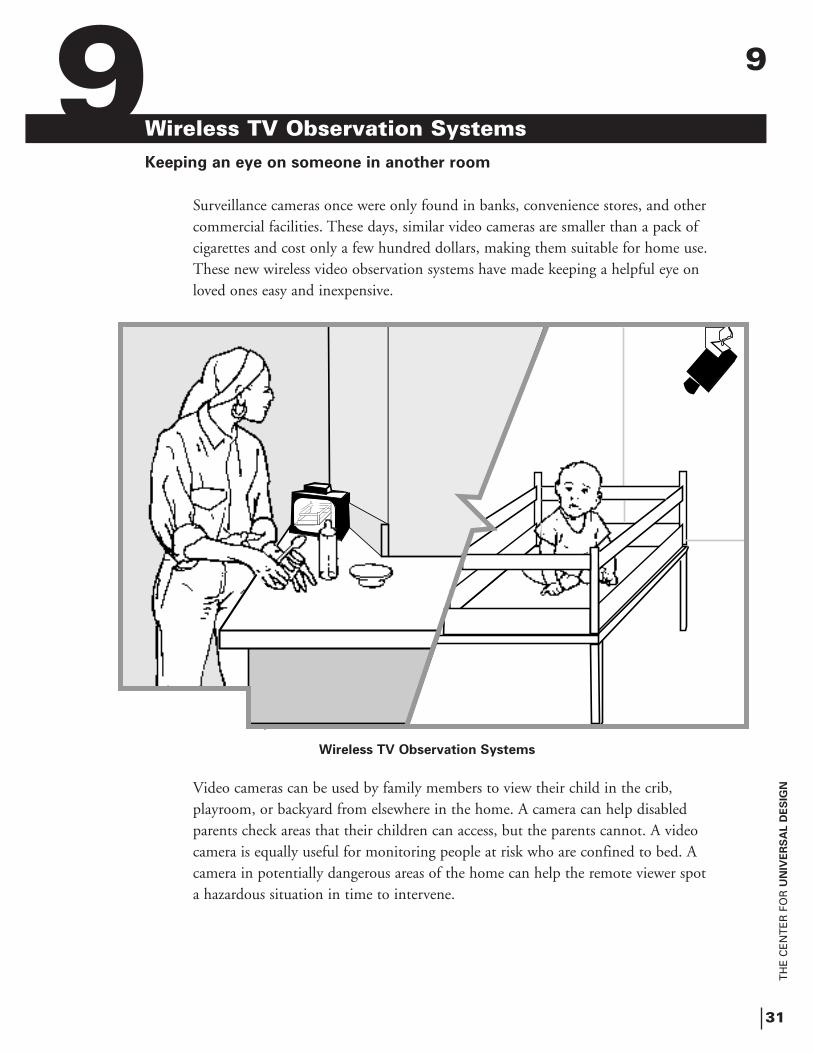
Wireless TV Observation SystemsKeeping an eye on someone in another room
Surveillance cameras once were only found in banks, convenience stores, and other commercial facilities. These days, similar video cameras are smaller than a pack of cigarettes and cost only a few hundred dollars, making them suitable for home use. These new wireless video observation systems have made keeping a helpful eye on loved ones easy and inexpensive.
Video cameras can be used by family members to view their child in the crib, playroom, or backyard from elsewhere in the home. A camera can help disabled parents check areas that their children can access, but the parents cannot. A video camera is equally useful for monitoring people at risk who are confined to bed. A camera in potentially dangerous areas of the home can help the remote viewer spot a hazardous situation in time to intervene.
Wireless TV Observation Systems
9 9
TH
E C
EN
TE
R F
OR
UN
IVE
RS
AL D
ES
IGN
32
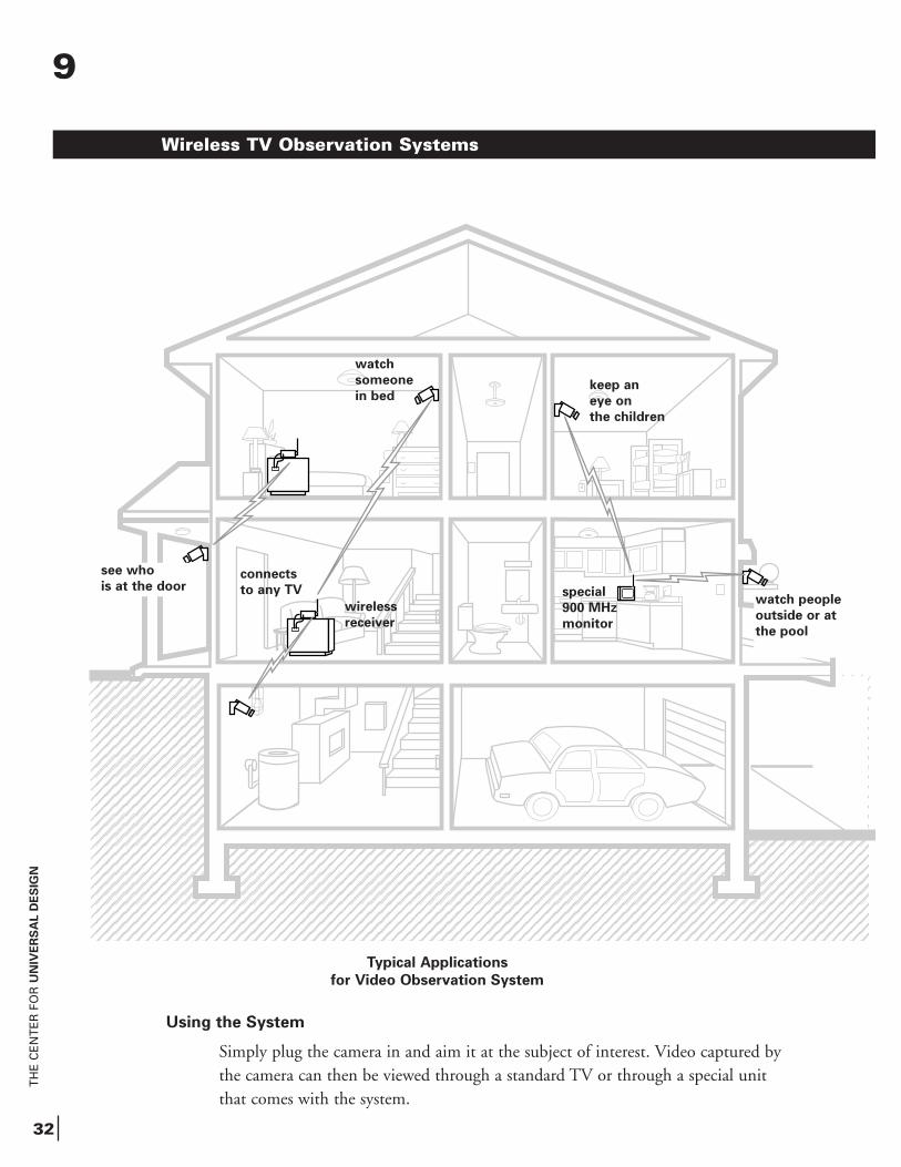
Using the System
Simply plug the camera in and aim it at the subject of interest. Video captured by the camera can then be viewed through a standard TV or through a special unit that comes with the system.
Typical Applications
for Video Observation System
Wireless TV Observation Systems
keep an
eye on
the children
watch
someone
in bed
connects
to any TV
wireless
receiver
special
900 MHz
monitor
watch people
outside or at
the pool
9
see who
is at the door
TH
E C
EN
TE
R F
OR
UN
IVE
RS
AL D
ES
IGN
33
How the System Works
The system operates just like a miniature TV station. In this case, the TV station broadcasts the signal from just one camera. Since the FCC licenses regular TV frequencies, wireless observation systems must broadcast on different radio frequencies(typically 900 MHz). These frequencies are unlicensed, although there are limits set on the amount of power to be transmitted. Because of this, the range of these systemsis limited to about 100 feet. Because the observation systems don’t use traditional TV frequencies, they require a special TV or a converter which changes the signal to one that a standard TV can receive.
What to Buy
There are many wireless observation systems on the market. They are available at many retail stores and through electronics catalogs. They generally range in price from $180 to $400. Selected models are suitable for outdoor use. The following represent a sample of the systems that are available.
s The Fisher Price Baby Camera and the Smart Choice BabyCam. Each of these systems uses a special portable 5-inch TV monitor. The cameras come with special infrared light emitters allowing short-distance visibility in total darkness.
s The Goldbeam Wireless Observation System permits viewing via an ordinaryTV set through the use of a small receiver/converter which converts the 900 MHz to a regular TV station. This system has been available through the Damark catalog.
s The Silent Witness Observation System has a wireless camera suitable for outdoor use; however, it must be supplied with low-voltage power. It is available through most security product distributors, such as ADI and Alarm-It.
Installing the System
A typical installation consists of mounting the camera to a convenient surface, plugging it in, and pointing it at the object of interest. If the system comes with its own TV monitor, all you have to do is turn the monitor on to watch it. If you have the type with a separate receiver/converter, you need to connect the receiver/converterto the antenna or video inputs of any TV. Turn on the TV to the channel which displays the camera image and the camera view appears.
Wireless TV Observation Systems
9

TH
E C
EN
TE
R F
OR
UN
IVE
RS
AL D
ES
IGN
10
TH
E C
EN
TE
R F
OR
UN
IVE
RS
AL D
ES
IGN
35
In-House Telephone/Intercom SystemsCommunicating with others inside and outside the home
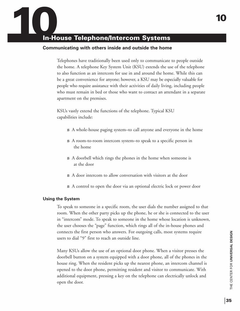
Telephones have traditionally been used only to communicate to people outside the home. A telephone Key System Unit (KSU) extends the use of the telephone to also function as an intercom for use in and around the home. While this can be a great convenience for anyone; however, a KSU may be especially valuable for people who require assistance with their activities of daily living, including people who must remain in bed or those who want to contact an attendant in a separate apartment on the premises.
KSUs vastly extend the functions of the telephone. Typical KSU capabilities include:
s A whole-house paging system–to call anyone and everyone in the home
s A room-to-room intercom system–to speak to a specific person in the home
s A doorbell which rings the phones in the home when someone is at the door
s A door intercom to allow conversation with visitors at the door
s A control to open the door via an optional electric lock or power door
Using the System
To speak to someone in a specific room, the user dials the number assigned to that room. When the other party picks up the phone, he or she is connected to the user in “intercom” mode. To speak to someone in the home whose location is unknown, the user chooses the “page” function, which rings all of the in-house phones and connects the first person who answers. For outgoing calls, most systems require users to dial “9” first to reach an outside line.
Many KSUs allow the use of an optional door phone. When a visitor presses the doorbell button on a system equipped with a door phone, all of the phones in the house ring. When the resident picks up the nearest phone, an intercom channel is opened to the door phone, permitting resident and visitor to communicate. With additional equipment, pressing a key on the telephone can electrically unlock and open the door.
10
How the System Works
The KSU consists of circuitry that routes outside or inside calls to the appropriate person. The KSU responds to a call coming from outside the house by sending a ring signal to all the phones in the home. When an extension is dialed from within the house, the KSU sends a ring signal to a selected phone (or all the phones in “page” mode). When that phone is answered, the KSU connects the two extensions as an intercom. Door phones work in much the same way. When the doorbell button is pressed, the KSU responds by ringing all the phones within the house. The phone answered first is then connected to the door phone via intercom. Many KSUs can also be signaled to close a switch, which disengages an electric lock or opens a power door.
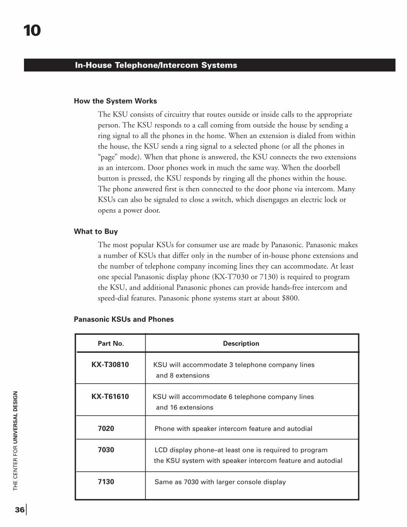
What to Buy
The most popular KSUs for consumer use are made by Panasonic. Panasonic makesa number of KSUs that differ only in the number of in-house phone extensions andthe number of telephone company incoming lines they can accommodate. At least one special Panasonic display phone (KX-T7030 or 7130) is required to program the KSU, and additional Panasonic phones can provide hands-free intercom and speed-dial features. Panasonic phone systems start at about $800.
Panasonic KSUs and Phones
Part No. Description
KX-T30810 KSU will accommodate 3 telephone company lines
and 8 extensions
KX-T61610 KSU will accommodate 6 telephone company lines
and 16 extensions
7020 Phone with speaker intercom feature and autodial
7030 LCD display phone–at least one is required to program
the KSU system with speaker intercom feature and autodial
7130 Same as 7030 with larger console display
TH
E C
EN
TE
R F
OR
UN
IVE
RS
AL D
ES
IGN
36
In-House Telephone/Intercom Systems
10
TH
E C
EN
TE
R F
OR
UN
IVE
RS
AL D
ES
IGN
37
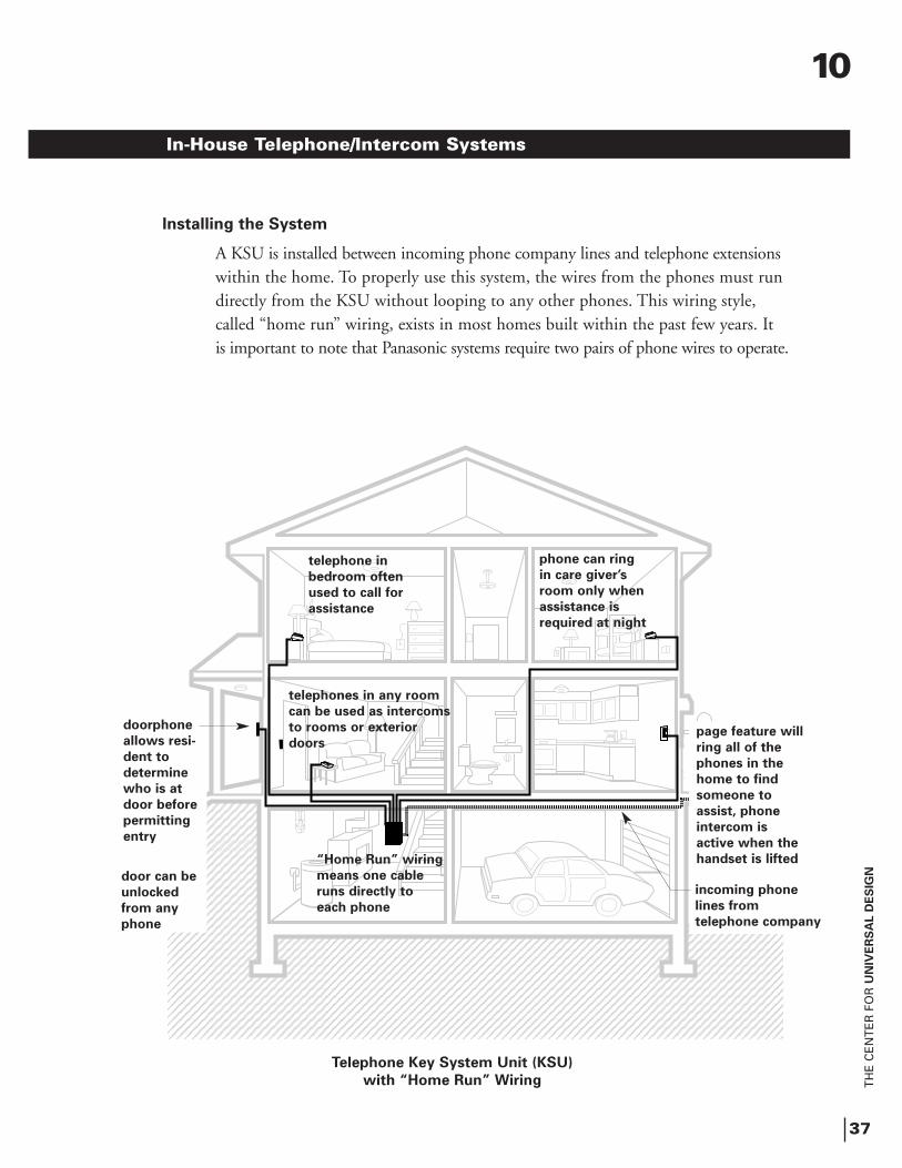
Installing the System
A KSU is installed between incoming phone company lines and telephone extensionswithin the home. To properly use this system, the wires from the phones must run directly from the KSU without looping to any other phones. This wiring style, called “home run” wiring, exists in most homes built within the past few years. It is important to note that Panasonic systems require two pairs of phone wires to operate.
In-House Telephone/Intercom Systems
��
Telephone Key System Unit (KSU)
with “Home Run” Wiring
telephone in
bedroom often
used to call for
assistance
phone can ring
in care giver’s
room only when
assistance is
required at night
telephones in any room
can be used as intercoms
to rooms or exterior
doors
“Home Run” wiring
means one cable
runs directly to
each phone
10
incoming phone
lines from
telephone company
page feature will
ring all of the
phones in the
home to find
someone to
assist, phone
intercom is
active when the
handset is lifted
doorphone
allows resi-
dent to
determine
who is at
door before
permitting
entry
door can be
unlocked
from any
phone
TH
E C
EN
TE
R F
OR
UN
IVE
RS
AL D
ES
IGN
38
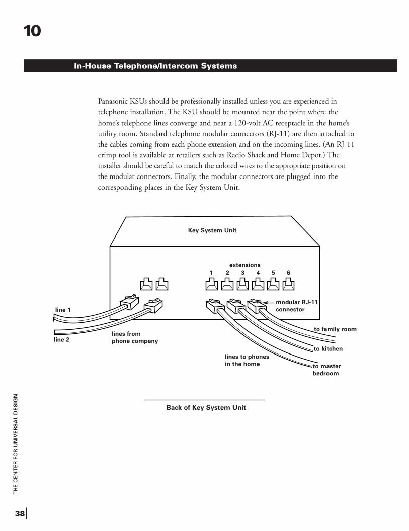
Panasonic KSUs should be professionally installed unless you are experienced intelephone installation. The KSU should be mounted near the point where the home’s telephone lines converge and near a 120-volt AC receptacle in the home’s utility room. Standard telephone modular connectors (RJ-11) are then attached to the cables coming from each phone extension and on the incoming lines. (An RJ-11crimp tool is available at retailers such as Radio Shack and Home Depot.) The installer should be careful to match the colored wires to the appropriate position on the modular connectors. Finally, the modular connectors are plugged into the corresponding places in the Key System Unit.
Back of Key System Unit
In-House Telephone/Intercom Systems
line 1
line 2lines from
phone company
lines to phones
in the home
to family room
to kitchen
to master
bedroom
Key System Unit
10
extensions
1 2 3 4 5 6
modular RJ-11
connector
11
TH
E C
EN
TE
R F
OR
UN
IVE
RS
AL D
ES
IGN
39
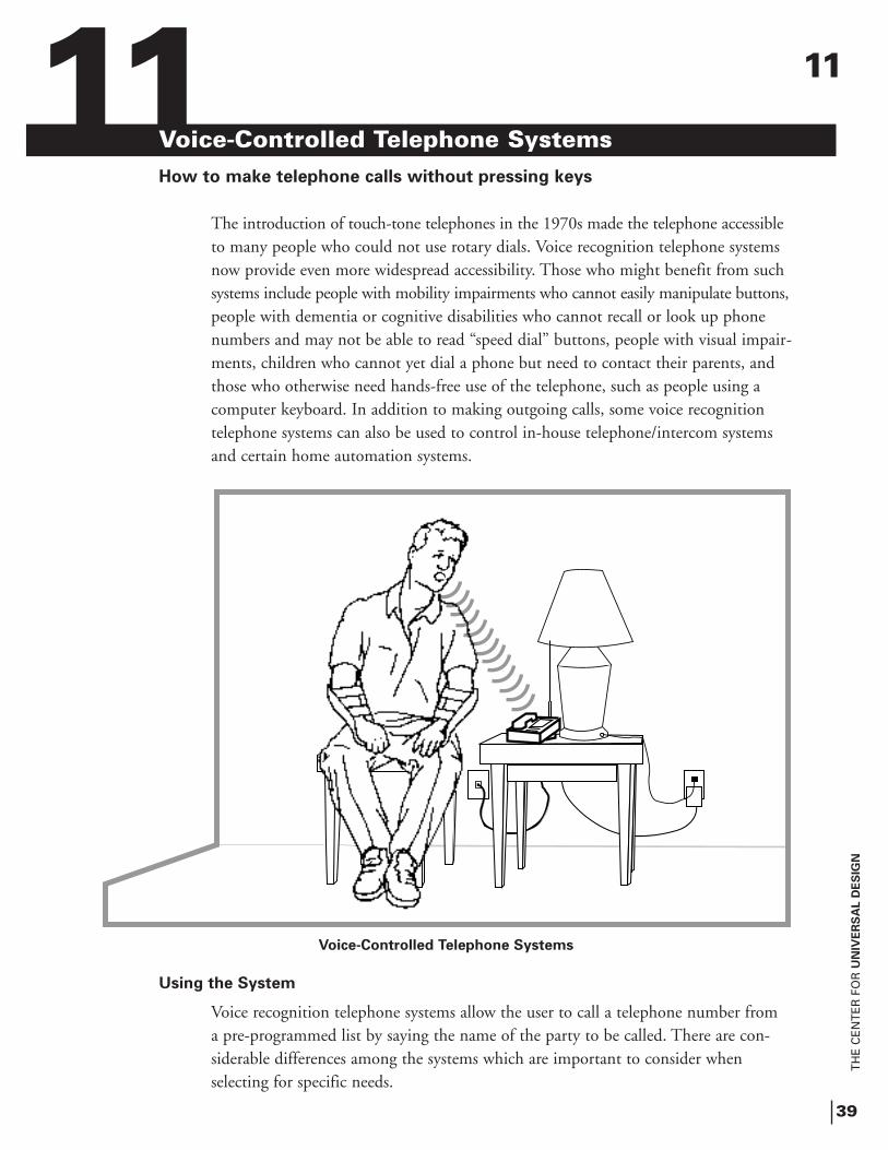
Voice-Controlled Telephone SystemsHow to make telephone calls without pressing keys
The introduction of touch-tone telephones in the 1970s made the telephone accessibleto many people who could not use rotary dials. Voice recognition telephone systems now provide even more widespread accessibility. Those who might benefit from such systems include people with mobility impairments who cannot easily manipulate buttons,people with dementia or cognitive disabilities who cannot recall or look up phone numbers and may not be able to read “speed dial” buttons, people with visual impair-ments, children who cannot yet dial a phone but need to contact their parents, and those who otherwise need hands-free use of the telephone, such as people using a computer keyboard. In addition to making outgoing calls, some voice recognition telephone systems can also be used to control in-house telephone/intercom systems and certain home automation systems.
Using the System
Voice recognition telephone systems allow the user to call a telephone number from a pre-programmed list by saying the name of the party to be called. There are con-siderable differences among the systems which are important to consider when selecting for specific needs.
Voice-Controlled Telephone Systems
11
TH
E C
EN
TE
R F
OR
UN
IVE
RS
AL D
ES
IGN
40
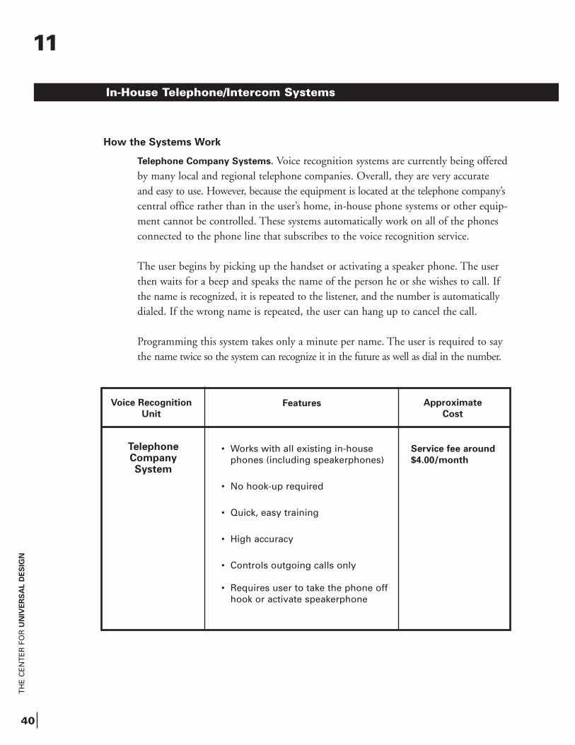
In-House Telephone/Intercom Systems
Voice Recognition
Unit
Features Approximate
Cost
• Works with all existing in-house phones (including speakerphones)
• No hook-up required
• Quick, easy training
• High accuracy
• Controls outgoing calls only
• Requires user to take the phone off hook or activate speakerphone
Service fee around
$4.00/month
11
How the Systems Work
Telephone Company Systems. Voice recognition systems are currently being offeredby many local and regional telephone companies. Overall, they are very accurate and easy to use. However, because the equipment is located at the telephone company’scentral office rather than in the user’s home, in-house phone systems or other equip-ment cannot be controlled. These systems automatically work on all of the phones connected to the phone line that subscribes to the voice recognition service.
The user begins by picking up the handset or activating a speaker phone. The user then waits for a beep and speaks the name of the person he or she wishes to call. If the name is recognized, it is repeated to the listener, and the number is automaticallydialed. If the wrong name is repeated, the user can hang up to cancel the call.
Programming this system takes only a minute per name. The user is required to say the name twice so the system can recognize it in the future as well as dial in the number.
Telephone CompanySystem
TH
E C
EN
TE
R F
OR
UN
IVE
RS
AL D
ES
IGN
41
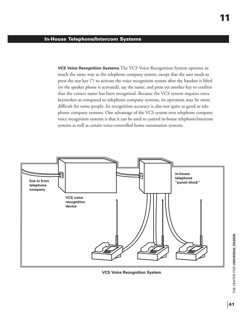
In-House Telephone/Intercom Systems
11
in-house
telephone
“punch block”line in from
telephone
company
VCS voice
recognition
device
VCS Voice Recognition System
VCS Voice Recognition Systems.The VCS Voice Recognition System operates in much the same way as the telephone company system, except that the user needs to press the star key (*) to activate the voice recognition system after the handset is lifted(or the speaker phone is activated), say the name, and press yet another key to confirmthat the correct name has been recognized. Because the VCS system requires extra keystrokes as compared to telephone company systems, its operation may be more difficult for some people. Its recognition accuracy is also not quite as good as tele-phone company systems. One advantage of the VCS system over telephone company voice recognition systems is that it can be used to control in-house telephone/intercom systems as well as certain voice-controlled home automation systems.
TH
E C
EN
TE
R F
OR
UN
IVE
RS
AL D
ES
IGN
42
In-House Telephone/Intercom Systems
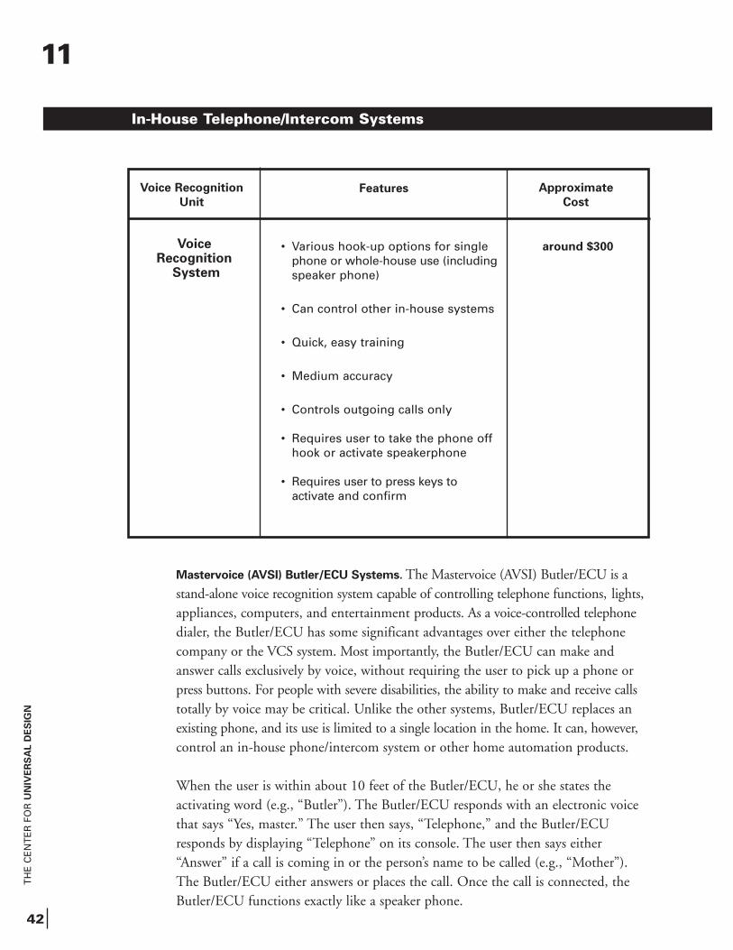
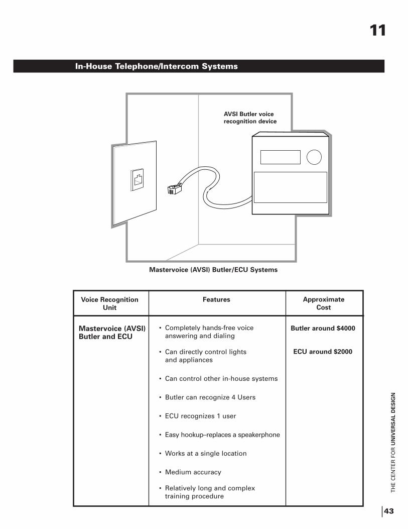
Mastervoice (AVSI) Butler/ECU Systems. The Mastervoice (AVSI) Butler/ECU is a stand-alone voice recognition system capable of controlling telephone functions, lights,appliances, computers, and entertainment products. As a voice-controlled telephone dialer, the Butler/ECU has some significant advantages over either the telephone company or the VCS system. Most importantly, the Butler/ECU can make and answer calls exclusively by voice, without requiring the user to pick up a phone or press buttons. For people with severe disabilities, the ability to make and receive callstotally by voice may be critical. Unlike the other systems, Butler/ECU replaces an existing phone, and its use is limited to a single location in the home. It can, however,control an in-house phone/intercom system or other home automation products.
When the user is within about 10 feet of the Butler/ECU, he or she states the activating word (e.g., “Butler”). The Butler/ECU responds with an electronic voice that says “Yes, master.” The user then says, “Telephone,” and the Butler/ECU responds by displaying “Telephone” on its console. The user then says either “Answer” if a call is coming in or the person’s name to be called (e.g., “Mother”). The Butler/ECU either answers or places the call. Once the call is connected, the Butler/ECU functions exactly like a speaker phone.
11
Voice Recognition
Unit
Features Approximate
Cost
• Various hook-up options for single phone or whole-house use (includingspeaker phone)
• Can control other in-house systems
• Quick, easy training
• Medium accuracy
• Controls outgoing calls only
• Requires user to take the phone off hook or activate speakerphone
• Requires user to press keys to activate and confirm
around $300Voice Recognition
System
TH
E C
EN
TE
R F
OR
UN
IVE
RS
AL D
ES
IGN
43
In-House Telephone/Intercom Systems
Voice Recognition
Unit
Features Approximate
Cost
• Completely hands-free voice answering and dialing
• Can directly control lights and appliances
• Can control other in-house systems
• Butler can recognize 4 Users
• ECU recognizes 1 user
• Easy hookup–replaces a speakerphone
• Works at a single location
• Medium accuracy
• Relatively long and complex training procedure
Mastervoice (AVSI)Butler and ECU
Butler around $4000
ECU around $2000
AVSI Butler voice
recognition device
Mastervoice (AVSI) Butler/ECU Systems
11
TH
E C
EN
TE
R F
OR
UN
IVE
RS
AL D
ES
IGN
44
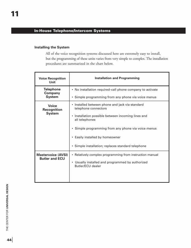
TelephoneCompanySystem
Voice Recognition
Unit
Installation and Programming
Voice Recognition
System
Mastervoice (AVSI)Butler and ECU
• No installation required–call phone company to activate
• Simple programming from any phone via voice menus
• Installed between phone and jack via standard telephone connectors
• Installation possible between incoming lines and all telephones
• Simple programming from any phone via voice menus
• Easily installed by homeowner
• Simple installation; replaces standard telephone
• Relatively complex programming from instruction manual
• Usually installed and programmed by authorized Butler/ECU dealer
Installing the System
All of the voice recognition systems discussed here are extremely easy to install, but the programming of these units varies from very simple to complex. The installationprocedures are summarized in the chart below.
In-House Telephone/Intercom Systems
11
12
TH
E C
EN
TE
R F
OR
UN
IVE
RS
AL D
ES
IGN
45
Electronic Alternatives to KeysEasily unlocking the door without a key
Although small and inexpensive, standard door keys have some disadvantages. Good vision and coordination are required to insert a key into the small keyhole, strength is needed to turn it, and sometimes both hands must be used to open the door. Keys are easy to copy and, if a key gets into the wrong hands, the lock must be changed.
Modern technology has come up with a number of devices that can unlock doors more easily than standard keys. These controls can work with an electric lock to unlock the door and, when necessary, a power door operator to electronically open the door.
Using the System
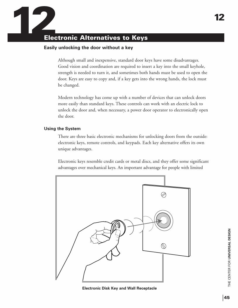
There are three basic electronic mechanisms for unlocking doors from the outside:electronic keys, remote controls, and keypads. Each key alternative offers its own unique advantages.
Electronic keys resemble credit cards or metal discs, and they offer some significantadvantages over mechanical keys. An important advantage for people with limited
Electronic Disk Key and Wall Receptacle
12
TH
E C
EN
TE
R F
OR
UN
IVE
RS
AL D
ES
IGN
46
strength or coordination is that electronic keys don’t have to be inserted into a small keyhole. Electronic keys are generally held up to or slid through a device that recognizesthe pattern in the key’s electronic memory and disengages the lock. Some electronickeys, called “proximity cards,” can actually be read from up to two feet away. Unlikemechanical locks, electronic keys can be programmed to allow access only at specifiedtimes (i.e., to allow domestic or medical assistants to enter only when expected) and are easily reprogrammed to deny access to workers who are no longer employed.
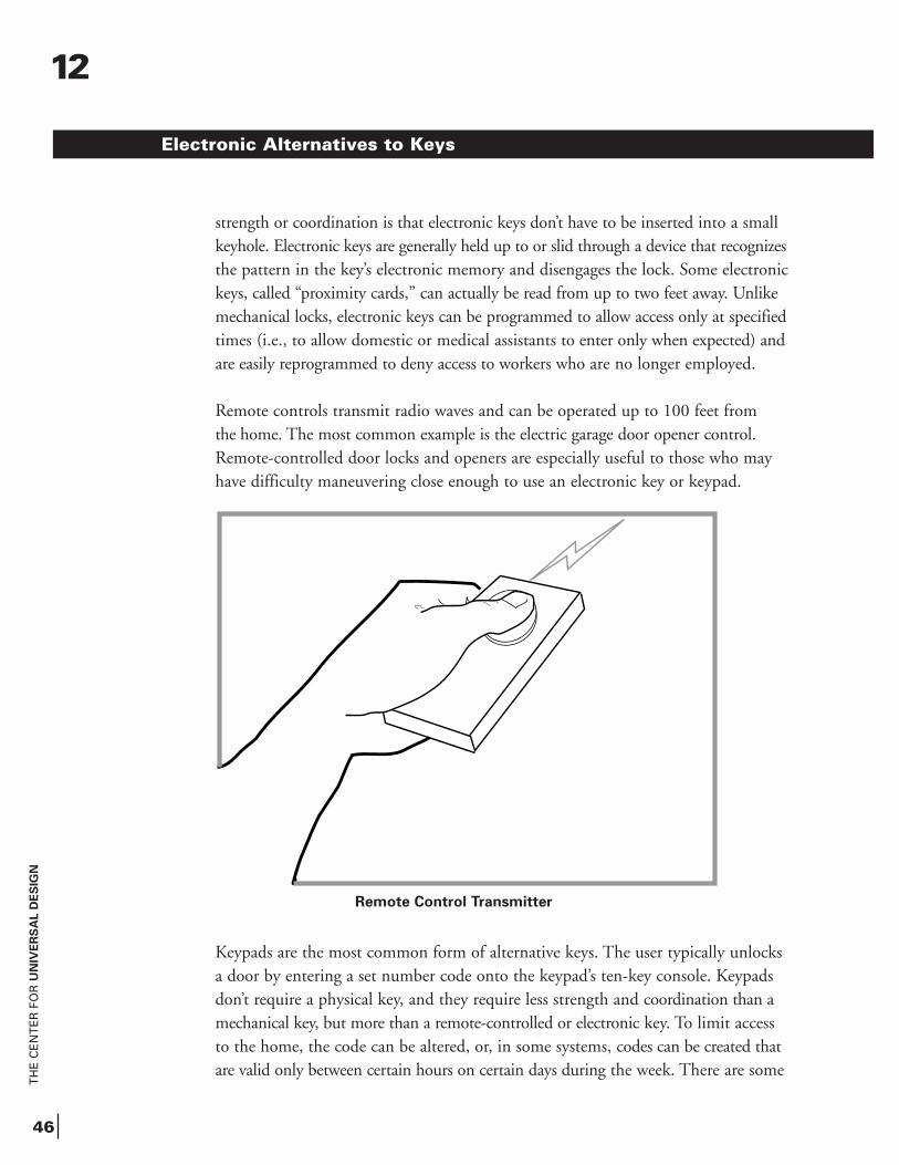
Remote controls transmit radio waves and can be operated up to 100 feet from the home. The most common example is the electric garage door opener control.Remote-controlled door locks and openers are especially useful to those who may have difficulty maneuvering close enough to use an electronic key or keypad.
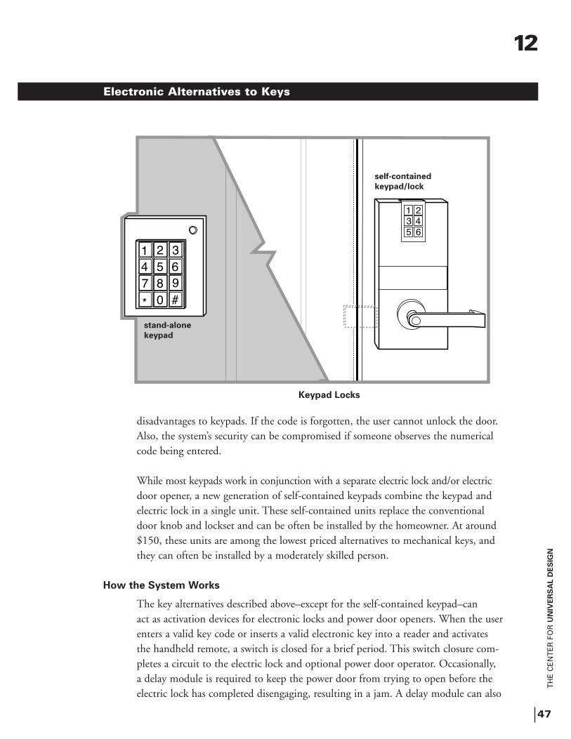
Keypads are the most common form of alternative keys. The user typically unlocks a door by entering a set number code onto the keypad’s ten-key console. Keypads don’t require a physical key, and they require less strength and coordination than a mechanical key, but more than a remote-controlled or electronic key. To limit access to the home, the code can be altered, or, in some systems, codes can be created that are valid only between certain hours on certain days during the week. There are some
Electronic Alternatives to Keys
Remote Control Transmitter
12
TH
E C
EN
TE
R F
OR
UN
IVE
RS
AL D
ES
IGN
47
disadvantages to keypads. If the code is forgotten, the user cannot unlock the door. Also, the system’s security can be compromised if someone observes the numerical code being entered.
While most keypads work in conjunction with a separate electric lock and/or electricdoor opener, a new generation of self-contained keypads combine the keypad and electric lock in a single unit. These self-contained units replace the conventional door knob and lockset and can be often be installed by the homeowner. At around $150, these units are among the lowest priced alternatives to mechanical keys, and they can often be installed by a moderately skilled person.
How the System Works
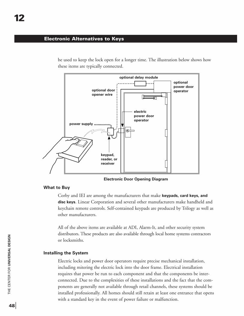
The key alternatives described above–except for the self-contained keypad–can act as activation devices for electronic locks and power door openers. When the userenters a valid key code or inserts a valid electronic key into a reader and activates the handheld remote, a switch is closed for a brief period. This switch closure com-pletes a circuit to the electric lock and optional power door operator. Occasionally, a delay module is required to keep the power door from trying to open before the electric lock has completed disengaging, resulting in a jam. A delay module can also
Electronic Alternatives to Keys
1 23 45 6
�
1 2 34 5 67 8 9
0* #
Keypad Locks
stand-alone
keypad
self-contained
keypad/lock
12
TH
E C
EN
TE
R F
OR
UN
IVE
RS
AL D
ES
IGN
48
be used to keep the lock open for a longer time. The illustration below shows how these items are typically connected.
What to Buy
Corby and IEI are among the manufacturers that make keypads, card keys, and
disc keys. Linear Corporation and several other manufacturers make handheld andkeychain remote controls. Self-contained keypads are produced by Trilogy as well as other manufacturers.
All of the above items are available at ADI, Alarm-It, and other security system distributors. These products are also available through local home systems contractorsor locksmiths.
Installing the System
Electric locks and power door operators require precise mechanical installation, including mitering the electric lock into the door frame. Electrical installation requires that power be run to each component and that the components be inter-connected. Due to the complexities of these installations and the fact that the com-ponents are generally not available through retail channels, these systems should be installed professionally. All homes should still retain at least one entrance that openswith a standard key in the event of power failure or malfunction.
Electronic Alternatives to Keys
Electronic Door Opening Diagram
power supply
optional door
opener wire
keypad,
reader, or
receiver
optional
power door
operator
optional delay module
12
electric
power door
operator