Embed Size (px)
Citation preview

LIGO R&D 1G050486-00-R
Wireless optical controls of LIGO static suspensions actuators
Maria Paola ClariziaUniversity of Sannio
Mentor: Riccardo De SalvoCalum Torrie

LIGO R&D 2G050486-00-R
The aim of this project
A wireless control of a stepper motor to be used to balance the MIRROR suspension system of Advanced LIGO

LIGO R&D 3G050486-00-R
Seismic noise
At very low frequencies, seismic motions may dominate the detectors' noise, degrading their sensitivity
The suspension system provides an isolation of the mirrors from the ground motion
For Advanced LIGO a quadrupole pendulum mirror suspension is used

LIGO R&D 4G050486-00-R
The suspension system
ATTENUATED
OPTICAL BENCH
22 Kg
22 Kg
40 Kg
40 Kg

LIGO R&D 5G050486-00-R
The tuning mass
THE
TUNING
MASS

LIGO R&D 6G050486-00-R
PROBLEMPROBLEM: no tuning is possible once the vacuum chamber is close
SOLUTIONSOLUTION: remote control of the mass to adjust the pitch of the mirror
METHODMETHOD: a stepping motor,which will move its own mass by means of a threaded shaft

LIGO R&D 7G050486-00-R
A wireless circuit to control the motor, in order to eliminate mechanical and electrical perturbations on the suspended masses, as well as an excessive load of outgas on vacuum.
The idea

LIGO R&D 8G050486-00-R
What is a stepping motor?
It’s an electric motor that rotates in small discrete steps (1.6O)
An internal rotor containing permanent magnets is controlled by a set of stationary electromagnets that are switched electronically
Stepping motors provide position holding torque while not in motion.

LIGO R&D 9G050486-00-R
How to make steps
A burst of current in the two coils is required to generate a step.
Coil 1
Coil 2
Steps Coil 1 Coil 2
1 + i
2 + i
3 - i
4 - i

LIGO R&D 10G050486-00-R
How to test the motor
• A charge is stored on a capacitor
• A burst of current is injected in the coils by means of FET switches
LIGO R&D 11G050486-00-R
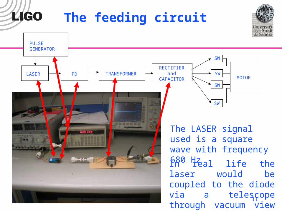
The feeding circuit
PD TRANSFORMERRECTIFIER
and CAPACITOR MOTOR
SW
SW
SW
SW
LASER
The LASER signal used is a square wave with frequency 680 Hz
PULSE GENERATOR
In real life the laser would be coupled to the diode via a telescope through vacuum view port

LIGO R&D 12G050486-00-R
Some specs
The laser:
Max control freq.: DC to 300 kHz
Output power: 1 mW
Wavelength: 635 nm
The silicon detector:
Responsitivity (at 635 nm) = 0.42 A/W
The output current of the detector is about 0.42 mA

LIGO R&D 13G050486-00-R
The transformer
The main formula:
1
2
2
1
2
1
I
I
N
N
V
V
...but actually it’s not so simple!!!
LIGO R&D 14G050486-00-R
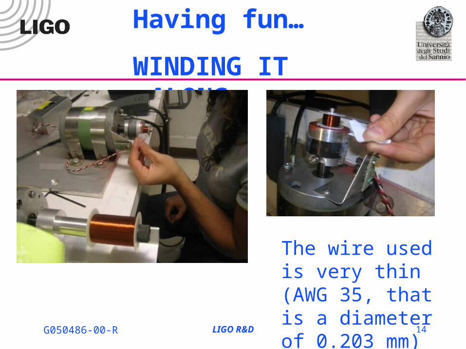
Having fun…
WINDING IT ALONG
The wire used is very thin (AWG 35, that is a diameter of 0.203 mm)

LIGO R&D 15G050486-00-R
Influences on the voltage
The voltage that can be obtained on the secondary strongly depends on:
The wire choice
The section of the FERRITE core
The excitation frequency
Increasing the section of the FERRITE core, the frequency corresponding to the maximum voltage decreases
LIGO R&D 16G050486-00-R
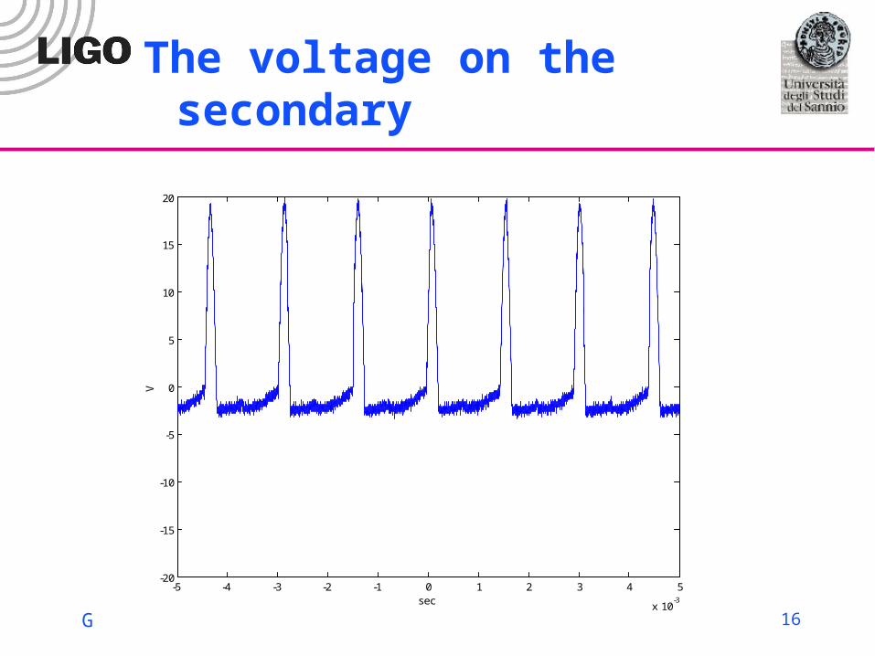
The voltage on the secondary
-5 -4 -3 -2 -1 0 1 2 3 4 5
x 10-3
-20
-15
-10
-5
0
5
10
15
20
sec
V

LIGO R&D 17G050486-00-R
The rectifier
this kind of rectifier gives a DC voltage which is the peak peak voltage of the wave coming from the transformer (a SMALL voltage drop is due to the diodes).
1
2

LIGO R&D 18G050486-00-R
Impedance matching
The rectifier impedance changes while the capacitor charges up.
-5 -4 -3 -2 -1 0 1 2 3 4 5
x 10-3
-6
-4
-2
0
2
4
6
sec
V
-5 -4 -3 -2 -1 0 1 2 3 4 5
x 10-3
-6
-4
-2
0
2
4
6
sec
V
-5 -4 -3 -2 -1 0 1 2 3 4 5
x 10-3
-6
-4
-2
0
2
4
6
sec
V

LIGO R&D 19G050486-00-R
Choice of the capacitor
The generation of a MOTOR step requires a certain amount of charge.
The bigger the capacitance, the slower the charging up TIME, but the smaller the capacitance, the higher the voltage required for A motor STEP.
The capacitance has to be big enough to defeat stictions

LIGO R&D 20G050486-00-R
The capacitor chosen
Several charge up times have been measured for different values of the capacitance and different transformers.
A capacitor of 100µF seems to be a good tradeoff!
Voltage needed: 5 V
Time of wait for one step: approximately one minute WITH 1 mW LASER POWER

LIGO R&D 21G050486-00-R
The charging up curve

LIGO R&D 22G050486-00-R
Further improvements
The transformer used gives a good voltage, but it’s not optimized: a higher voltage could allow a smaller capacitor or a faster charge up time to be used.
Impedance mismatching should be taken into account
A laser with a larger power can be used to provide a stronger signal and to lower the waiting time for one step

LIGO R&D 23G050486-00-R
Next steps
Developing the FET SWITCH control circuit of the motor.
The principle is to use frequency jumps to control gates of FET switches and four bandpass filters to route the current pulses.

LIGO R&D 24G050486-00-R
acknoledgements
My mentors Riccardo De Salvo and Calum Torrie
My professor Innocenzo Pinto
Dave Grimmett, Paul Russel and Peter King
Marco Tarallo
Ilaria Taurasi
Yuri, Chiara, and all the italian people (including John HONORARY ITALIAN)
United states for:
•Wonderful places
•Wonderful people
•Wonderful cookies

LIGO R&D 25G050486-00-R
THAT’S IT !