Embed Size (px)
Citation preview
G070491-00-D
Electronics Infrastructure for advanced LIGO
LSC Meeting, Boston, July 25, 2007
Daniel Sigg, LIGO Hanford Observatory
LSC Meeting, Boston 2G070491-00-D
Outline
Converter Design Commercial baseline: Currently runs the prototypes New design: Low noise ADC/DAC/uplink boards
Timing System (with U of Columbia) New design based on fiber distribution/FPGA
Power Supplies Baseline: 48VDC distribution with local voltage regulators
EMI Plan (Huh?) Thermal Management
Possibility for water cooling
Slow Controls Epics based, no VME based systems
LSC Meeting, Boston 3G070491-00-D
Some Basic Design Guidelines
Digital controls whenever possible X86 architecture for controls; No VME
Stay with the current software infrastructure as much as possible Online digital filter code Frame builder & archival code Diagnostics and DMT software
No change in slow controls interface, i.e., EPICS No VME; maybe no dedicated slow controls hardware
In-vacuum detection benches
LSC Meeting, Boston 4G070491-00-D
Timing System
“The ability to reconstruct the arrival time of a gravitational wave signal with infinite signal-to-noise ratio shall be within 10 μs of UTC.”
Distribution Fiber based; bidirectional links for diagnostics and status Timing derived from GPS Master/fanout units & Slave units Full timestamp to ADC/DAC
Atomic clock Separate system for diagnostics Time-interval counters in each building
DuoTone (Two) sine waves for time encoding in data stream Hardware locking for DAC
LSC Meeting, Boston 5G070491-00-D
LSC Meeting, Boston 6G070491-00-D
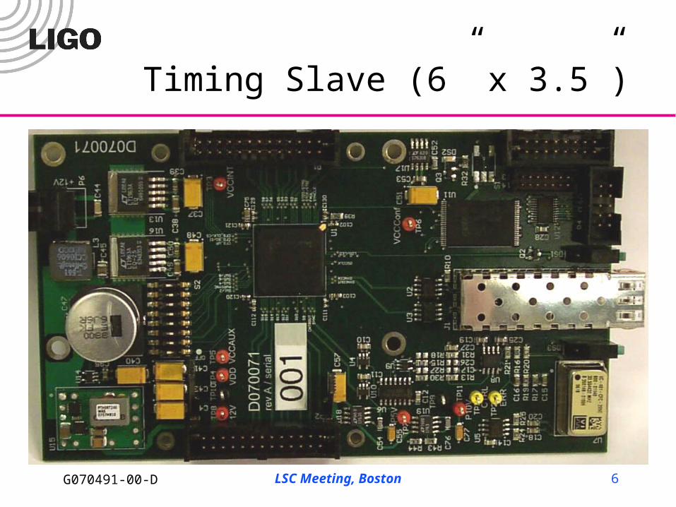
Timing Slave (6” x 3.5”)
LSC Meeting, Boston 7G070491-00-D
Converter DesignFeatures we like to address (I)
Co-location of analog and digital New design uses fiber links between computer and converter
PCI-E for commercial Gigabit ethernet for in-house design
All computers in mass storage room and out of LVEA
Poor noise performance Use over-sampling Better analog input circuits and cleaner power supplies
Limited Timing Support Ideally samples are time stamped at front-end Timing accuracy should be guaranteed in hardware
LSC Meeting, Boston 8G070491-00-D
Converter DesignFeatures we like to address (II)
Inadequate throughput Eliminate the VME backplane Replace with PCI-E or dedicated serial link (gigE)
Convoluted data paths No reflective memory Myrinet/10GE switched network between computers
High costs Better with PCI-E & in-house
LSC Meeting, Boston 9G070491-00-D
Basic Requirements for In-House Development
Absolute timing precision relative to UTC: 1μs Converter range: ±10V Converter noise: 100–300nV/√Hz (best effort) Latency between converter and processor: < 5μs No restriction on converter location No electrical connection between converters and
processors (fiber links) Detection of transmission and timing errors Support for diagnostics
LSC Meeting, Boston 10G070491-00-D
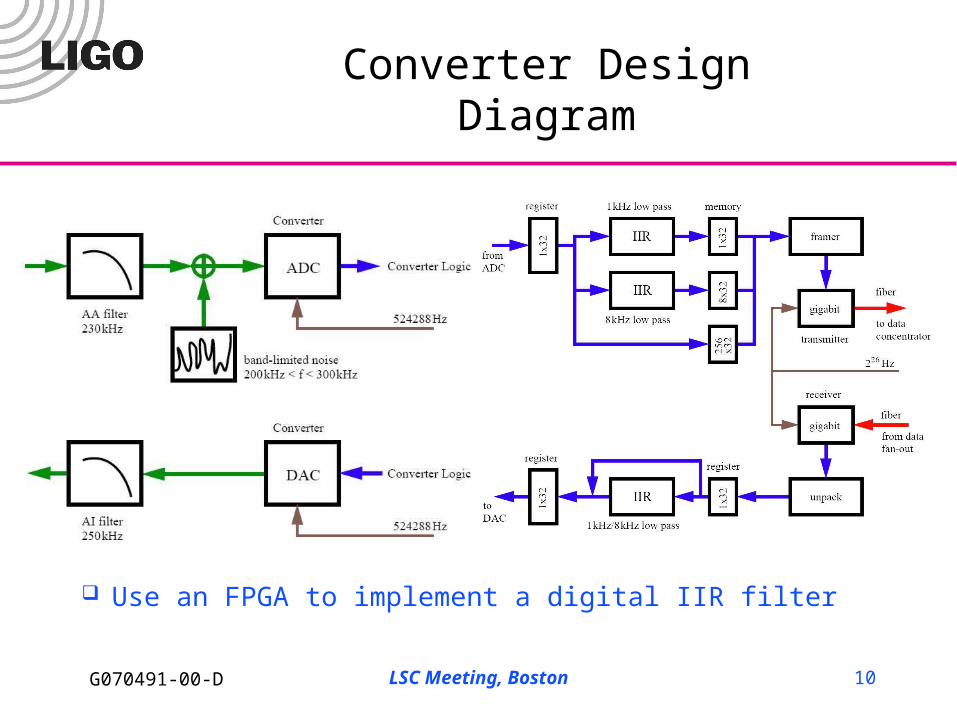
Converter DesignDiagram
Use an FPGA to implement a digital IIR filter
LSC Meeting, Boston 11G070491-00-D
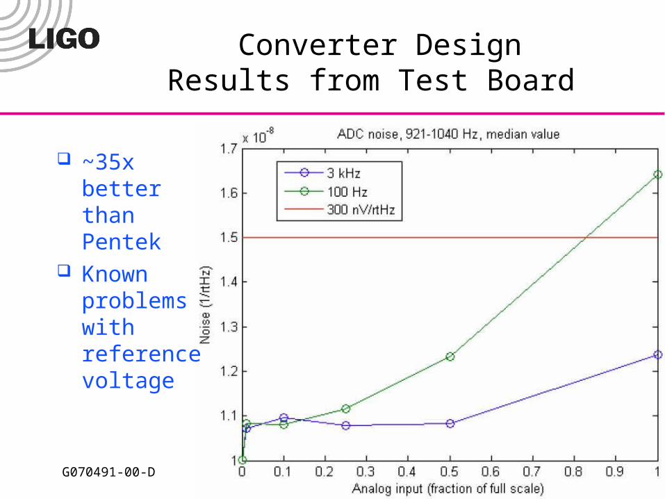
Converter DesignResults from Test Board
~35x better than Pentek
Known problems with reference voltage
LSC Meeting, Boston 12G070491-00-D
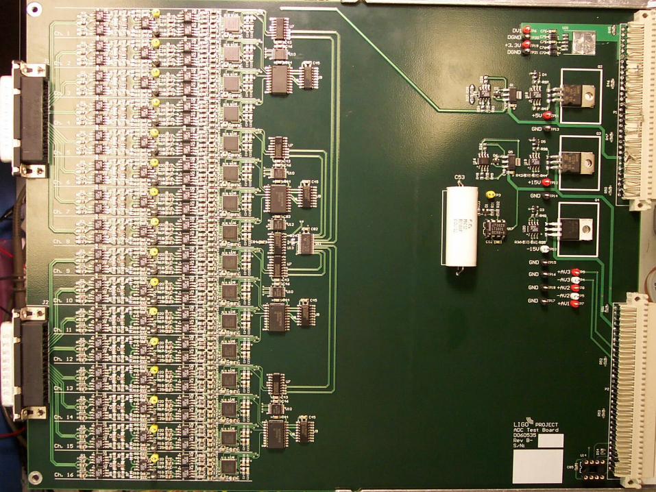
Converter DesignNew Boards
16 channels 6U x 280mm eurocrate form factor Differential signaling to uplink board (LVDS) ADC: Analog Devices AD7634
Fabricated and in testing
DAC: Texas Instruments (Burr-Brown) PCM1794A Design finished
Uplink for single converter board In design phase Xilinx Virtex 4 FX series (most likely)
LSC Meeting, Boston 13G070491-00-D
LSC Meeting, Boston 14G070491-00-D
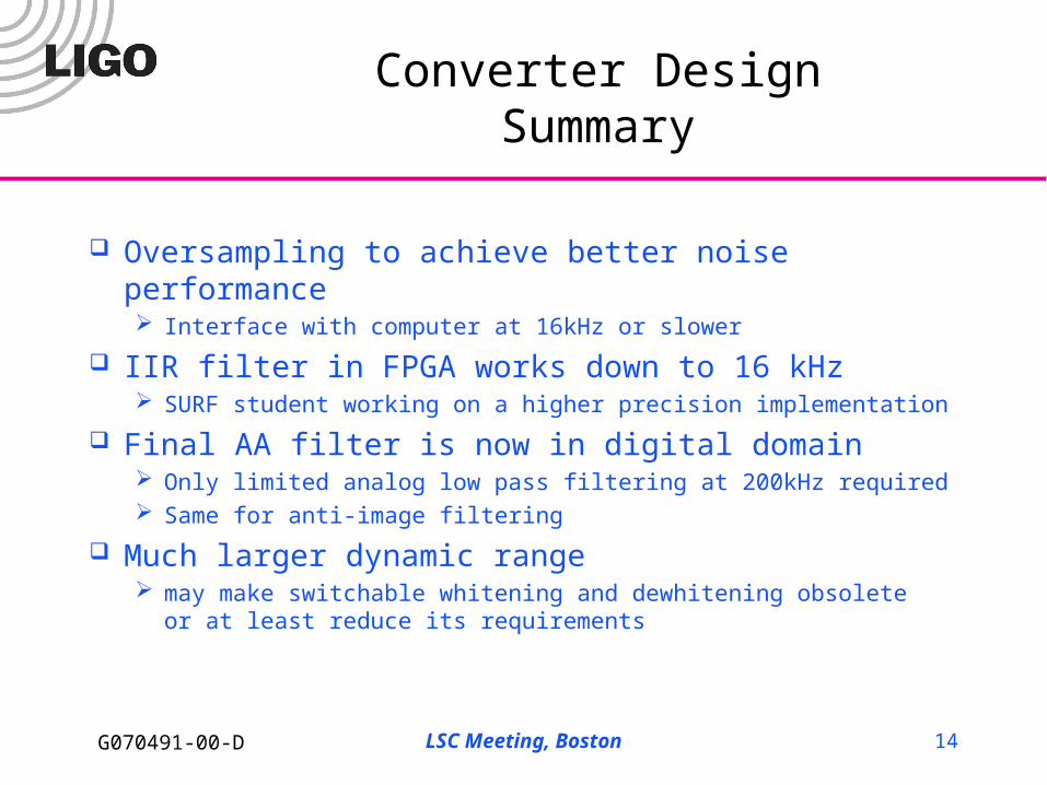
Converter DesignSummary
Oversampling to achieve better noise performance Interface with computer at 16kHz or slower
IIR filter in FPGA works down to 16 kHz SURF student working on a higher precision implementation
Final AA filter is now in digital domain Only limited analog low pass filtering at 200kHz required Same for anti-image filtering
Much larger dynamic range may make switchable whitening and dewhitening obsolete
or at least reduce its requirements
LSC Meeting, Boston 15G070491-00-D
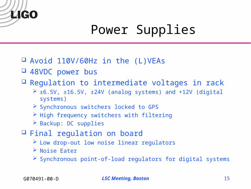
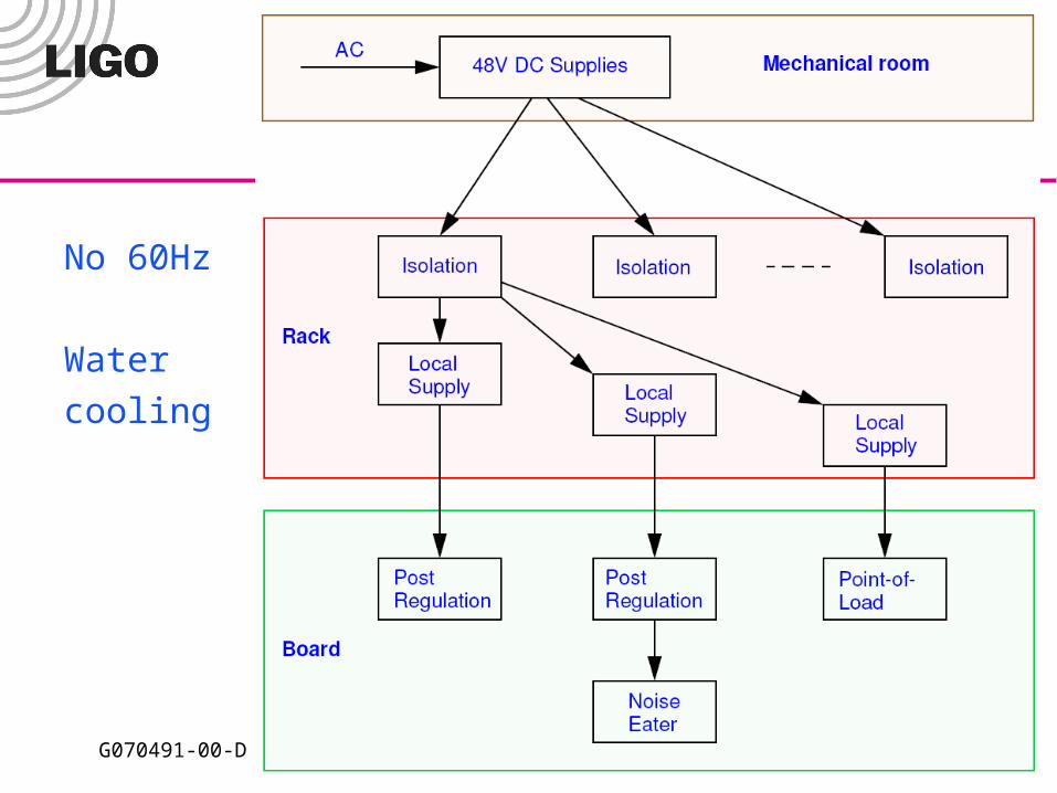
Power Supplies
Avoid 110V/60Hz in the (L)VEAs 48VDC power bus Regulation to intermediate voltages in rack
±6.5V, ±16.5V, ±24V (analog systems) and +12V (digital systems) Synchronous switchers locked to GPS High frequency switchers with filtering Backup: DC supplies
Final regulation on board Low drop-out low noise linear regulators Noise Eater Synchronous point-of-load regulators for digital systems
LSC Meeting, Boston 16G070491-00-D
No 60Hz
Water
cooling
LSC Meeting, Boston 17G070491-00-D
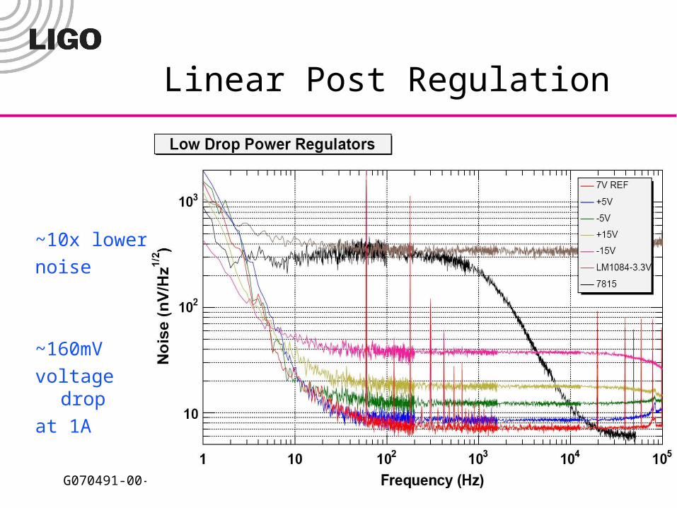
Linear Post Regulation
~10x lower
noise
~160mV
voltage drop
at 1A
LSC Meeting, Boston 18G070491-00-D
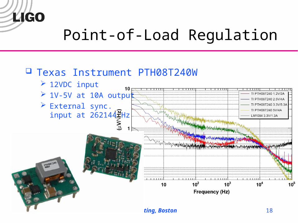
Point-of-Load Regulation
Texas Instrument PTH08T240W 12VDC input 1V-5V at 10A output External sync.
input at 262144 Hz
LSC Meeting, Boston 19G070491-00-D
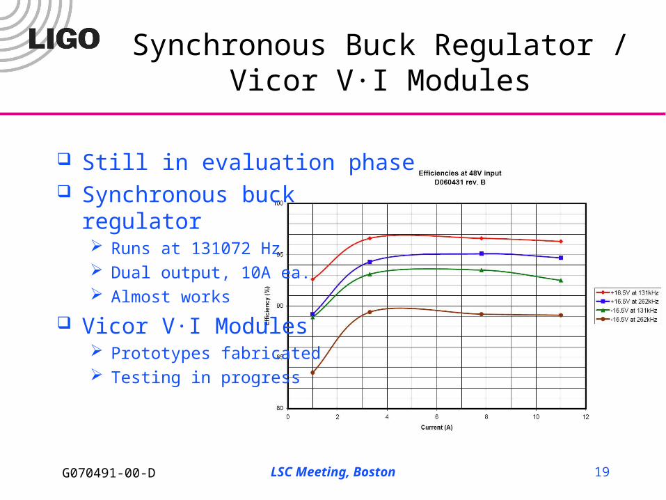
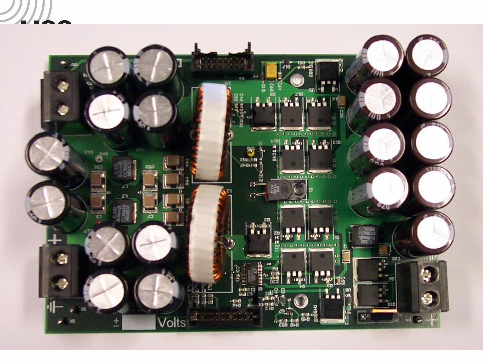
Synchronous Buck Regulator /Vicor V·I Modules
Still in evaluation phase Synchronous buck
regulator Runs at 131072 Hz Dual output, 10A ea. Almost works
Vicor V·I Modules Prototypes fabricated Testing in progress
LSC Meeting, Boston 20G070491-00-D
LSC Meeting, Boston 21G070491-00-D
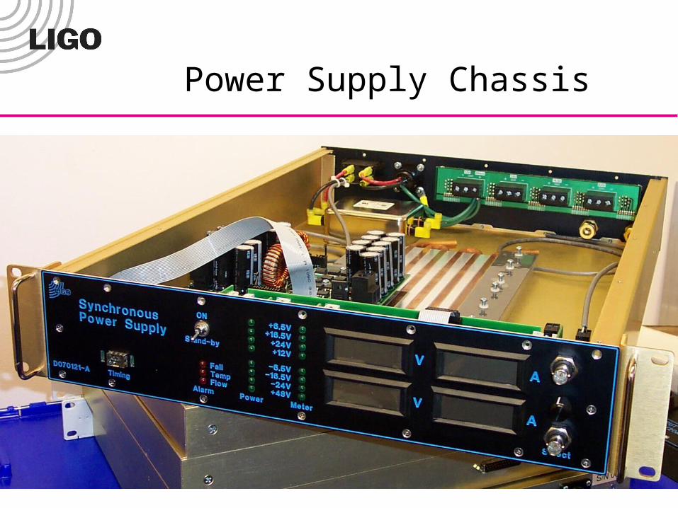
Power Supply Chassis
LSC Meeting, Boston 22G070491-00-D
Summary
New timing design well underway Hope to have final design by end of year
First prototype for new converter design is ready Hope to have noise performance evaluated by end of year Hope to have a full prototype with uplink mid next year
New ideas for power supplies under investigation Hope to have a design by mid next year