Embed Size (px)
Citation preview
1
G1000 CROSS TRACK SINGLE LEG METHOD
OVERVIEW
FOR A
PARALLEL GRID SEARCH
MIAMI 4D
from
Lakeland-Linder Regional Airport Florida (KLAL)
Starting Southwest Corner
East-West Tracks
2
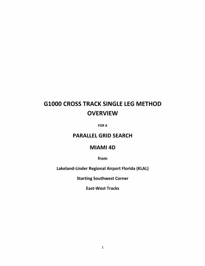
The corners of MIA4D are shown as G1, G2, G3, and G4. These are the waypoints
used for Cross Track Flight Plan Method. Only the G1 to G2 waypoints will be in
the single leg method flight plan.
SEARCH SPECIFICATION:
Miami 4D, start SW corner, East-West Tracks, 0.5 nm track spacing
3
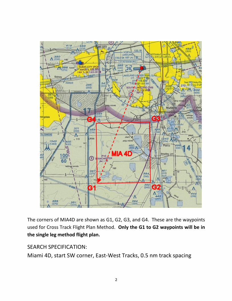
The aircraft is shown on the first search leg with the autopilot in NAV mode.
This is the corresponding MFD view of the PDF above.
4
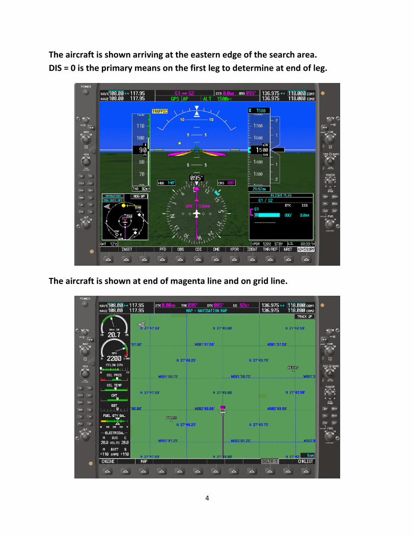
The aircraft is shown arriving at the eastern edge of the search area.
DIS = 0 is the primary means on the first leg to determine at end of leg.
The aircraft is shown at end of magenta line and on grid line.
5
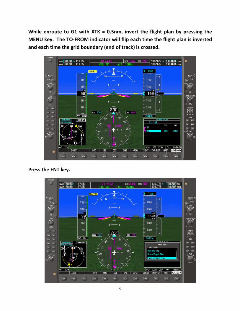
While enroute to G1 with XTK = 0.5nm, invert the flight plan by pressing the
MENU key. The TO-FROM indicator will flip each time the flight plan is inverted
and each time the grid boundary (end of track) is crossed.
Press the ENT key.
6
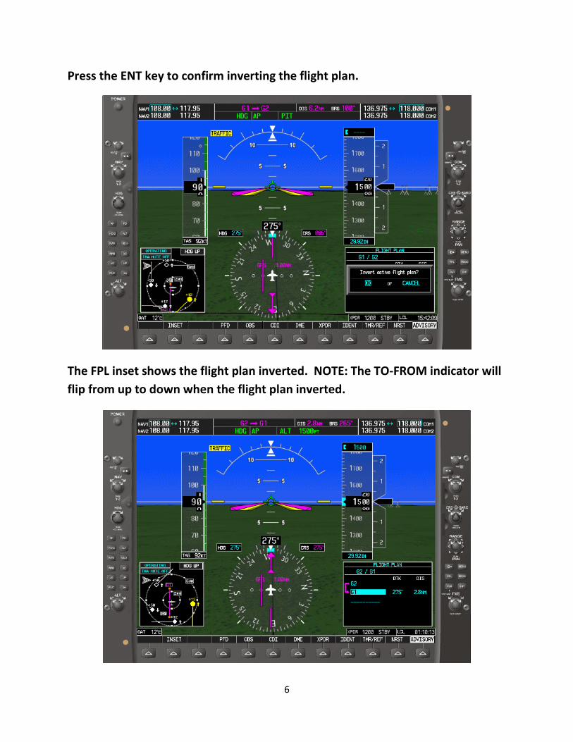
Press the ENT key to confirm inverting the flight plan.
The FPL inset shows the flight plan inverted. NOTE: The TO-FROM indicator will
flip from up to down when the flight plan inverted.
7
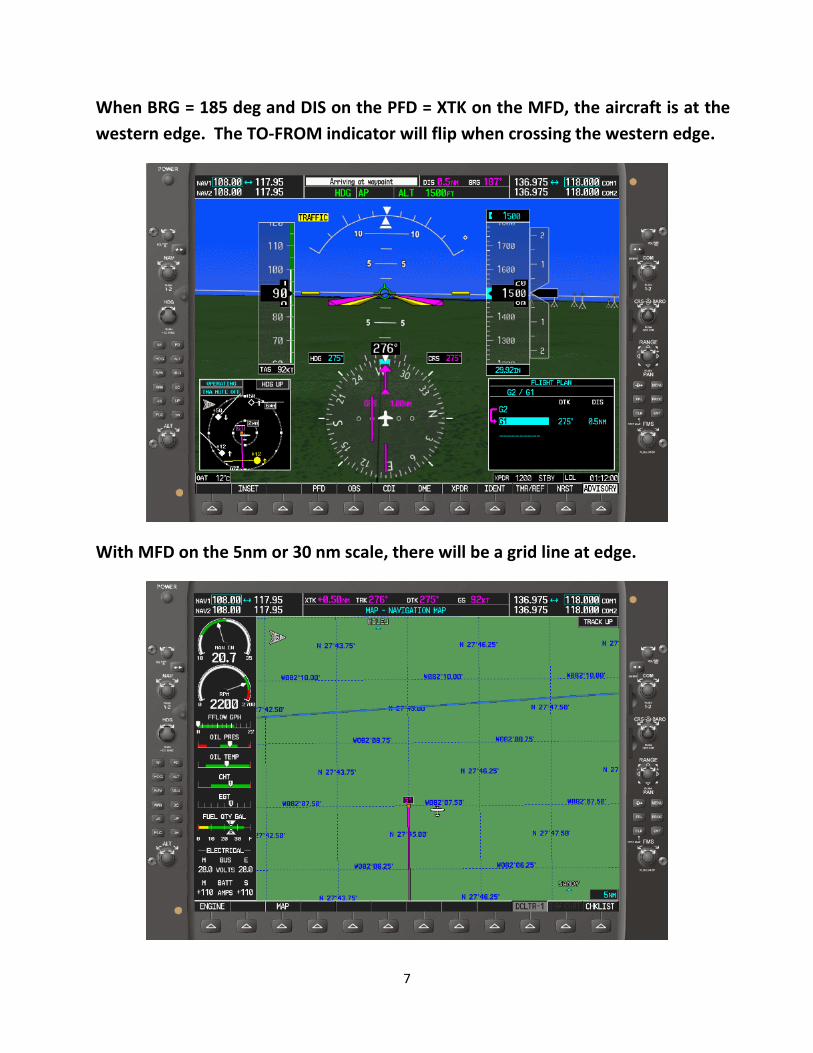
When BRG = 185 deg and DIS on the PFD = XTK on the MFD, the aircraft is at the
western edge. The TO-FROM indicator will flip when crossing the western edge.
With MFD on the 5nm or 30 nm scale, there will be a grid line at edge.
8
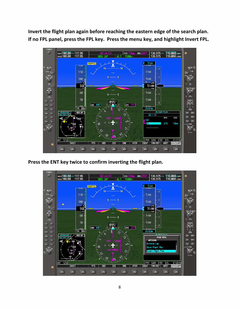
Invert the flight plan again before reaching the eastern edge of the search plan.
If no FPL panel, press the FPL key. Press the menu key, and highlight Invert FPL.
Press the ENT key twice to confirm inverting the flight plan.
9
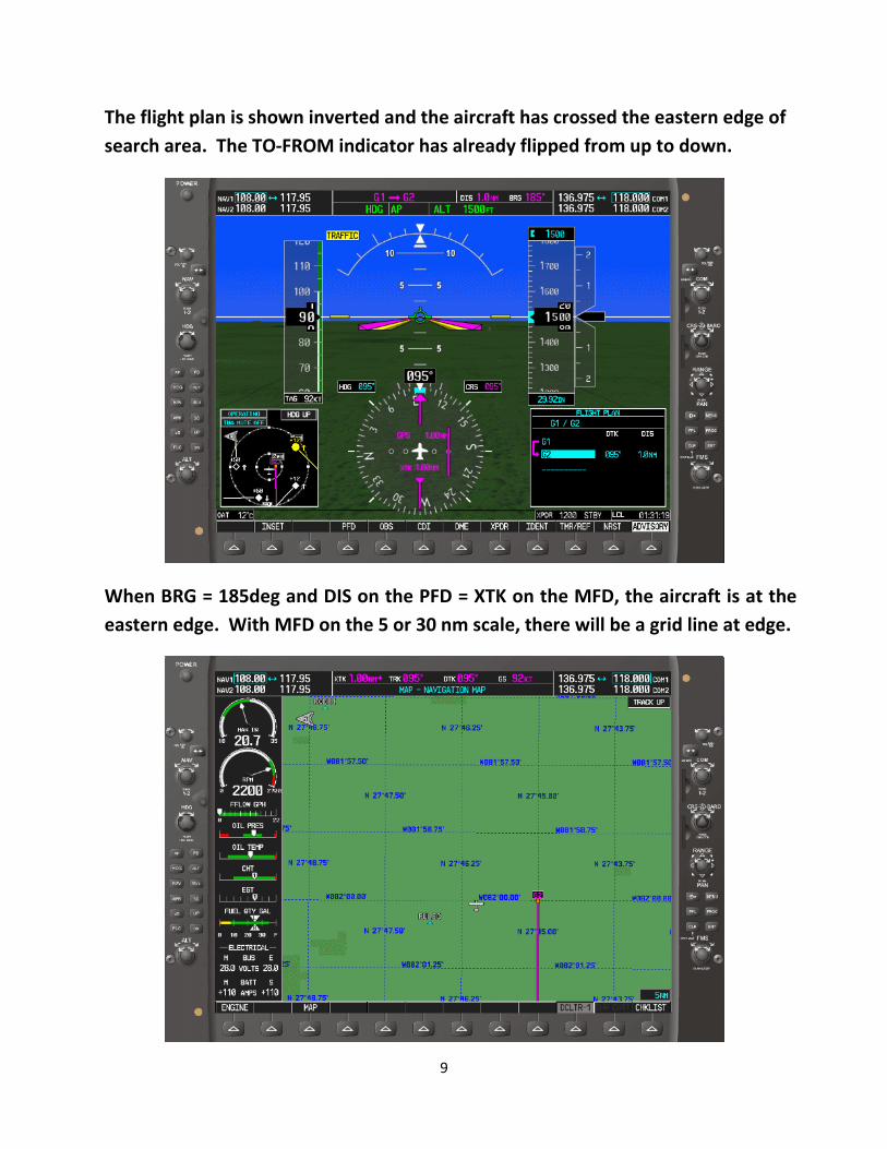
The flight plan is shown inverted and the aircraft has crossed the eastern edge of
search area. The TO-FROM indicator has already flipped from up to down.
When BRG = 185deg and DIS on the PFD = XTK on the MFD, the aircraft is at the
eastern edge. With MFD on the 5 or 30 nm scale, there will be a grid line at edge.
10
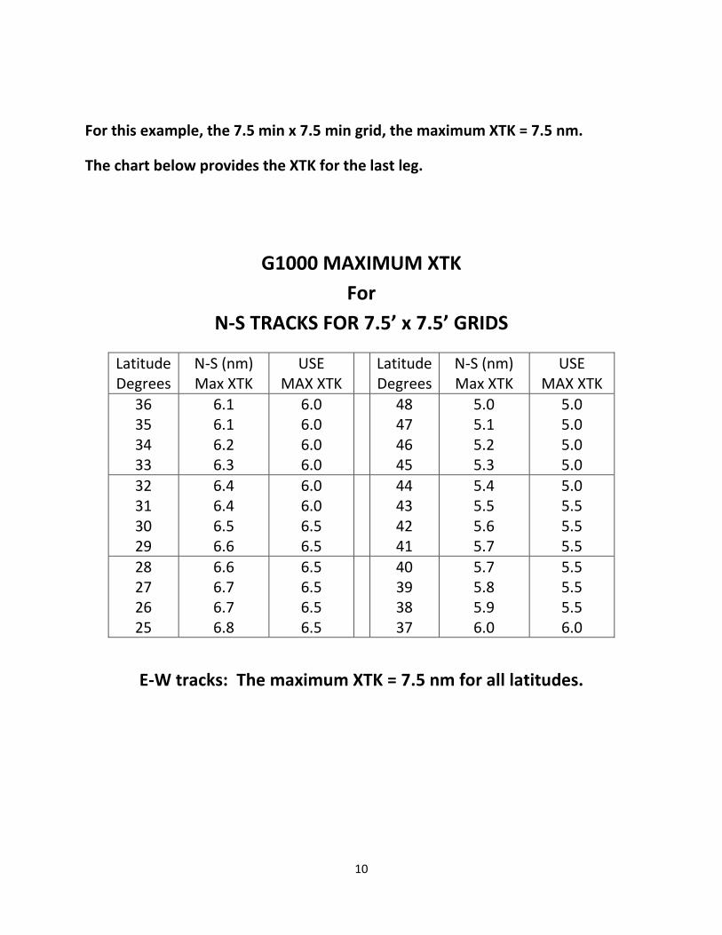
For this example, the 7.5 min x 7.5 min grid, the maximum XTK = 7.5 nm.
The chart below provides the XTK for the last leg.
G1000 MAXIMUM XTK
For
N-S TRACKS FOR 7.5’ x 7.5’ GRIDS
Latitude
Degrees
N-S (nm)
Max XTK
USE
MAX XTK
Latitude
Degrees
N-S (nm)
Max XTK
USE
MAX XTK
36
35
34
33
6.1
6.1
6.2
6.3
6.0
6.0
6.0
6.0
48
47
46
45
5.0
5.1
5.2
5.3
5.0
5.0
5.0
5.0
32
31
30
29
6.4
6.4
6.5
6.6
6.0
6.0
6.5
6.5
44
43
42
41
5.4
5.5
5.6
5.7
5.0
5.5
5.5
5.5
28
27
26
25
6.6
6.7
6.7
6.8
6.5
6.5
6.5
6.5
40
39
38
37
5.7
5.8
5.9
6.0
5.5
5.5
5.5
6.0
E-W tracks: The maximum XTK = 7.5 nm for all latitudes.
11
The Cross Track Single Leg method can be applied to other GPSs.
Use DIS = XTK to determine if close to the end of track, and the flipping of
the CDI TO-FROM indicator from up to down for the end of track. The BRG
will equal DTK + or – 90 degrees when TO-FROM indicator flips at the end
of track. The BRG will count up or down to the crossing bearing value
depending on track direction. One way the crossing bearing value will be
DTK + 90 degrees and the other way DTK – 90 degrees.
EXCEPTION: On the very first track with zero XTK, DIS will count down to
zero, and BRG will change 180 degrees abruptly at the end of track.
All CAP aircraft with the following GPSs have Course Deviation Indicators
(CDI) or Horizontal Situation Indicator (HSI) with a TO-FROM indicator.
Therefore, if BRG is not available or another parameter would be more
meaningful, use the TO-FROM indicator as primary for end of track.
The KLN 89B:
You only have DIS and XTK data parameters to work with for the KLN 89B.
Available Data Parameters:
DIS (hard wired)
WPT (hard wired)
DTK, GS, ETE, or XTK (XTK is required)
Even with the limited availability of parameters, the Cross Track Single
Leg is the best method for the KLN 89B for rectangular search areas.
The KLN 94B:
You have DIS – WPT – DTK – (TRK or BRG) – XTK to work with for the KL94B.
Available Data Parameters:
DIS (hard wired)
WPT (hard wired)
DTK (hard wired)
TRK, BRG, or RAD (TRK most useful) (RAD not applicable)
GS, ETE, XTK or VNAV (XTK is required)
12
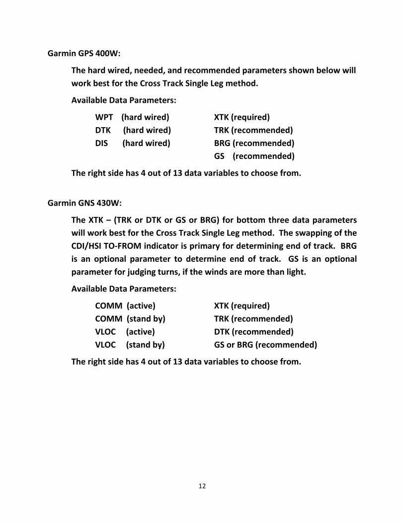
Garmin GPS 400W:
The hard wired, needed, and recommended parameters shown below will
work best for the Cross Track Single Leg method.
Available Data Parameters:
WPT (hard wired) XTK (required)
DTK (hard wired) TRK (recommended)
DIS (hard wired) BRG (recommended)
GS (recommended)
The right side has 4 out of 13 data variables to choose from.
Garmin GNS 430W:
The XTK – (TRK or DTK or GS or BRG) for bottom three data parameters
will work best for the Cross Track Single Leg method. The swapping of the
CDI/HSI TO-FROM indicator is primary for determining end of track. BRG
is an optional parameter to determine end of track. GS is an optional
parameter for judging turns, if the winds are more than light.
Available Data Parameters:
COMM (active) XTK (required)
COMM (stand by) TRK (recommended)
VLOC (active) DTK (recommended)
VLOC (stand by) GS or BRG (recommended)
The right side has 4 out of 13 data variables to choose from.
13
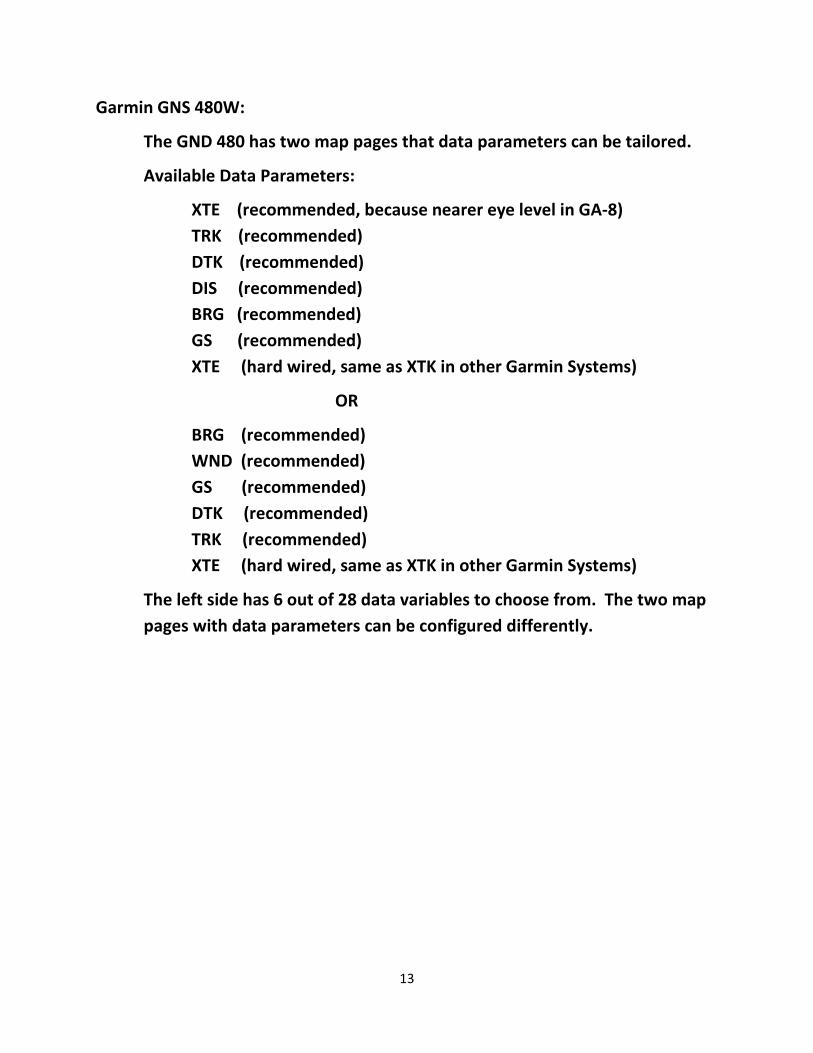
Garmin GNS 480W:
The GND 480 has two map pages that data parameters can be tailored.
Available Data Parameters:
XTE (recommended, because nearer eye level in GA-8)
TRK (recommended)
DTK (recommended)
DIS (recommended)
BRG (recommended)
GS (recommended)
XTE (hard wired, same as XTK in other Garmin Systems)
OR
BRG (recommended)
WND (recommended)
GS (recommended)
DTK (recommended)
TRK (recommended)
XTE (hard wired, same as XTK in other Garmin Systems)
The left side has 6 out of 28 data variables to choose from. The two map
pages with data parameters can be configured differently.