Embed Size (px)
Citation preview
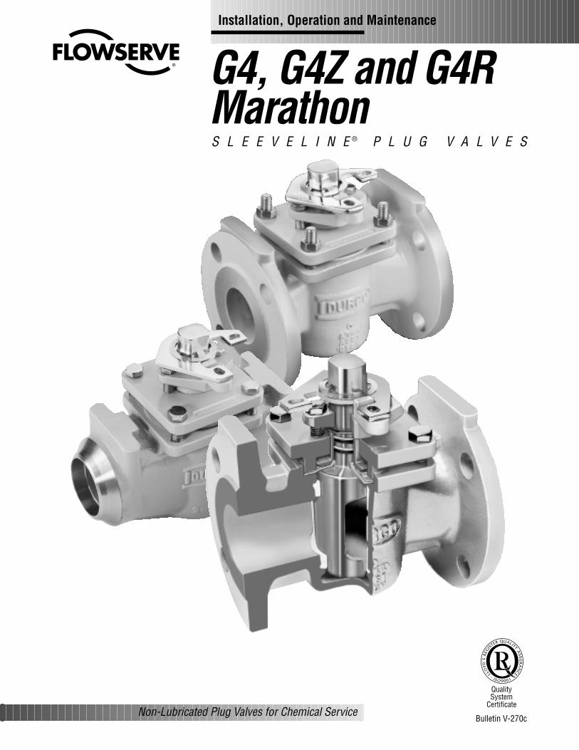
G4, G4Z and G4RMarathonS L E E V E L I N E ® P L U G V A L V E S
Non-Lubricated Plug Valves for Chemical Service
Quality System
Certificate
Bulletin V-270c
Installation, Operation and Maintenance
FOREWORDFlowserve Corporation, Flow Control Division, has establishedthis Installation, Operating, and Maintenance Manual to facili-tate field installation, operation and repair of G4 Marathon,G4Z Marathon and G4R Marathon valves.
It is recommended that questions or concerns involving theprocesses described in this manual be directed to the local
Sales Representative of Flowserve Corporation. OnlyFlowserve replacement repair parts and assembly toolingmade or designed by Flowserve Corporation should be used.Part numbers referenced in the following sections are avail-able from Flowserve Corporation, Flow Control Division.
TABLE OF CONTENTSSECTION TITLE PAGE
FOREWORD
I INSTALLATION INSTRUCTIONS – FLANGED AND WELDED G4 Marathon, G4Z Marathon, G4R Marathon 2
II OPERATING/MAINTENANCE – G4 Marathon, G4Z Marathon, G4R Marathon 3
III VALVE DISASSEMBLY – G4 Marathon, G4Z Marathon, G4R Marathon 4
IV PRESSURE CONTAINING FASTENERS 5-6
V A. VALVE ASSEMBLY – 1/2" & 3/4" G4 Marathon, G4R Marathon 7-8-9
B. VALVE ASSEMBLY – 1"-8" G4 Marathon, G4R Marathon 10-11-12
VI ASSEMBLY SPECIFICATIONS – FIRESAFE VALVES G4Z Marathon, G4ZR Marathon 13-14-15
VII RECOMMENDED SPARE PARTS 16
SECTION I
INSTALLATION INSTRUCTIONS – FLANGED AND WELDED G4 MARATHON, G4Z MARATHON, G4R MARATHON
FLANGED:Installation of Flowserve flanged valves is best accomplished bylocating valves in pipeline flanges, assuring all corrosion andforeign material are removed from pipe flange and then centergaskets with the valve flanges. Fasteners or taper pins shouldbe used to align holes and locate gaskets. Fasteners should betightened to the corresponding valve and fastener size.
WELDED:Flowserve Corporation, Flow Control Division recommendsusing only qualified welding procedures and personnel forweld installation of G4 Marathon and G4R Marathon valves.
The following precautions should be observed:1. The valve should be inspected prior to welding to assure
that no foreign materials obstruct the flow passagewayand that the weld preparations are free of corrosion andphysical damage.
2. The valve should be in the open position while being welded.Open position is when the flow indicator on the plug stem ispointing in the direction of the pipeline.
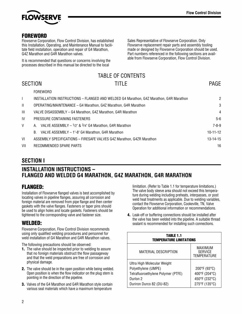
3. Valves of the G4 Marathon and G4R Marathon style containvarious seal materials which have a maximum temperature
limitation. (Refer to Table 1.1 for temperature limitations.)The valve body sleeve area should not exceed this tempera-ture during welding including preheats, interpasses, or postweld heat treatments as applicable. Due to welding variables,contact the Flowserve Corporation, Cookeville, TN, ValveOperation for additional information or recommendations.
4. Leak-off or buffering connections should be installed afterthe valve has been welded into the pipeline. A suitable threadsealant is recommended for installing such connections.
TABLE 1.1TEMPERATURE LIMITATIONS
MAXIMUMMATERIAL DESCRIPTION SERVICE
TEMPERATURE
Ultra High Molecular WeightPolyethylene (UMPE) 200°F (93°C)Tetrafluoroethylene Polymer (PTFE) 400°F (204°C)Durlon 2 450°F (232°C)Duriron Durco 82 (DU-82) 275°F (135°C)
2
Flow Control Division
Section 1.0

SECTION II
OPERATING/MAINTENANCE INSTRUCTIONS FOR G4 MARATHON, G4Z MARATHON, G4R MARATHON
Maintenance requirements for G4 Marathon, G4Z Marathonand G4R Marathon valves may vary due to operating condi-tions of the process. Factors such as operating temperature,pressure, solids content, and frequency of cycling can influ-ence valve performance and maintenance requirements.
Seal wear is compensated by adjusting appropriate parts. ForG4 Marathon, G4Z Marathon and G4R Marathon valves, thereare three possible leak paths:
1. Top Cap (bonnet)2. Stem3. Line (through)
Corresponding adjustments for each leak path are as follows:Note: Refer to Figure II-1 or Figure VI-1A for parts identification.
1. Top Cap (bonnet)Leakage due to thermal or pressure cycling is eliminatedby snugging the top cap fasteners (Part 3A) in a “criss-cross” pattern. This adjustment is most effective when thevalve is not pressurized. It is important that the top capfasteners not be tightened excessively and that torquevalues applied be within industry standard for fasteners.
2. StemLeakage due to wear of the diaphragm, and/or wear tothe sleeve (primary seal) is eliminated by tightening theadjuster fasteners (Part 12A) in 1/4 turn increments. It isrecommended that the adjuster fasteners be tightenedevenly.
The valve should be operated between adjustments toassure that the plug properly seats itself into the sleeve.If leakage persists after repeated adjustments, the sleeveand diaphragm will require replacement as covered inSection V A and V B or Section VI.
3. Line (through)Through leakage due to wear of the primary seal can beeliminated by tightening the adjuster fasteners (Part 12A)in 1/4 turn increments. It is recommended that thefasteners be tightened evenly.
The valve should be operated during adjustments to pre-vent excessive operating torque. Should leakage persistafter repeated adjustments, the sleeve will require replace-ment as covered in Section V A and V B or Section VI.
3
▲WARNINGTo avoid personal injury and prevent damage to equip-ment, do not operate or repair this valve without observ-ing the following procedures outlined in this manual.
!
Flow Control Division
Section 1.0
WRENCH (13)
STOP COLLAR RETAINER (19A)
STOP COLLAR (19)
ADJUSTER FASTENERS (12A)
ADJUSTER (12)
TOP CAP FASTENERS (3A)
TOP CAP (3)
GROUNDING SPRING (17)
THRUST COLLAR (11)
TEFLON BACK-UP RINGS (20) &O-RINGS (21)
DIAPHRAGM (6)
PLUG (2)
SLEEVE (5)
BODY (1)
FIGURE II-1TYPICAL ASSEMBLY OF G4 MARATHON AND G4R MARATHON VALVE

Recommended Precautionary Measures1. Valves must be relieved of process fluid and pressure
prior to disassembly.
2. Personnel performing disassembly must be suitablyprotected and alert for emission of hazardous processfluid.
3. If there is a pipe plug located at the bottom bowl ofthe valve, DO NOT remove the pipe plug until the valveplug has been removed.
Disassembly StepsNOTE: Refer to Figure II-1 or VI-1A for parts identification. Ifan actuator or gearbox operates the valve, alignment marksshould be noted to assure correct orientation when reassem-bled. This may best be accomplished by making matchingmarks on the plug stem and operator housing with no burrson the plug stem.
1. Gradually loosen adjuster fasteners (Part 12A) – DONOT REMOVE.
2. Turn plug (Part 2) in order to raise the plug to vent anymaterial trapped in the valve (see note below).
Note: If there is no upward movement of the plug(Part 2), it will be necessary to devise a method of liftingthe plug upward. This may require removal of the valveoperator (Step 3). This operation should be undertakennoting the above precautionary measures. Methods ofplug removal must include protective measures on plugstem and plug end.
3. WARNING: Do not loosen or remove top cap fasteners(Part 3A) when removing an operator or accessory.Remove the operator by unfastening it from thebracket.
4. Once the plug (Part 2) has lifted, the adjuster fasteners(Part 12A) can be completely removed.
5. Gradually loosen but DO NOT REMOVE all of the top capfasteners (Part 3A). Turn the plug until it is loose fromthe sleeve (Part 5) and all pressure has been vented.(Again, it may be necessary to use a mechanical meansto move the plug upwards.)
6. Remove the top cap fasteners (Part 3A) and top cap(Part 3) from the plug stem (Part 2).
7. Remove the plug (Part 2) from the body (Part 1).
8. Remove the grounding spring (Part 17) and thrust collar(Part 11) from plug stem (Part 2).
9. Remove the o-rings (Part 21), backup rings (Part 20) andthe diaphragm (Part 6) from the plug stem (Part 2).
10. Inspect the valve sleeve (Part 5) for wear or damage,especially scratches near the top, bottom, and port areas.If wear or damage is excessive, the sleeve should bereplaced.
11. Remove sleeve (Part 5) as follows:NOTE: Care should be taken not to damage the internalbody bore.a. Using a screw driver and mallet, cut the old sleeve
through one of the port openings, top and bottom.b. Grasp the sleeve with a pair of pliers while twisting,
and lift the sleeve from the body.
12. Thoroughly clean all valve parts with an acceptablecleaner.
13. Inspect parts for damage. Look for marred, scratched, orrough sealing surfaces on the valve plug (Part 2).
NOTE: Reinstallation of damaged or unclean parts willruin any replacement seals installed into the valve.
SECTION III
VALVE DISASSEMBLY – G4 MARATHON, G4Z MARATHON, G4R MARATHON
4
Flow Control Division
Section 1.0
TABLE 1CAP SCREWS - STUDS
HHCS - Finished Heavy Hex Head Cap Screw Alloy identification stamp required on each piece.HCS - Finished Hex Head Cap Screw Certification required.STUD - Stud Alloy Specification (40 KSI Minimum Yield Strength, 12% Minimum Elongation)Dimensions per ASME B18.2.1
B9 - Stainless Steel per ASTM A193, Class 2B, Grade B8 (AISI type 304)B16 Stainless Steel per ASTM A193, 100% hardness testedB7 - Chromium - Molybdenum Alloy Steel per ASTM A193, Grade B7B7M - Chromium - Molybdenum Alloy Steel per ASTM A193, Grade B7M, 100% hardness testedB7MT - Chromium - Molybdenum Alloy Steel per ASTM A193, Grade B7M, 100% hardness tested, Teflon® coated, Dupont SP11C, Type B - Color blue or greenB8M - 316 Stainless Steel per ASTM A193, Grade B8M, Class 1, 40 KSI Min. Yield Strength, 12% Min. El.B8C2 - 304 Stainless Steel per ASTM A193, Grade B8, Class 2C20 - Carpenter C20, CB-3 (UNS NO8020), ASTM B473, 40 KSI Min. Yield Strength, 12% Min. El.HC - Hastelloy C276 (UNS N10276), ASTM B574I625 - Inconel 625 (UNS N006625), ASTM B446I825 Incoloy 825 (UNS N08825), ASTM B425, 40 KSI Min. Yield Strength, 12% Min. El.IN - Inconel 600 (UNS N0660), ASTM B166, 40 KSI Min. Yield Strength, 12% Min. El.M - Monel (UNS N04400), ASTM B164, Class A or B, 40 KSI Min. Yield Strength, 12% Min. El.HB - Hastelloy B (UNS 10665), ASTM B335I718 - Incoloy 718, AMS 5595B MKH - Monel K-500, Cold drawn and aged hardened, QQN-286 and ASTM F468L7 - Chromium-Molybdenum Alloy Steel per ASTM A320, Grade L7L7M - Chromium-Molybdenum Alloy Steel per ASTM A320, Grade L7M, 100% hardness testedL7T - Chromium-Molybdenum Alloy Steel per ASTM A320, Grade L7, Teflon® coated, Dupont SP11C, Type B - Color blue or greenL7MT - Chromium-Molybdenum Alloy Steel per ASTM A320, Grade L7M, 100% hardness tested, Teflon® coated, Dupont SP11C, Type B - Color blue or greenN - Nickel per ASTM B160 (UNS N0220), 40 KSI Min. Yield Strength, 12% Min. El.B7YC - Chromium-Molybdenum Alloy Steel per A193, Grade B7, Yellow Zinc Dichromate Plated
Material SelectionSelecting the proper fastener material is the ultimate responsi-bility of the customer because the supplier does not typicallyknow in what service the valves will be used or what elementsmay be present in the environment. Flowserve normally sup-plies B7 (carbon steel) for ductile cast iron and carbon steelvalves. For stainless steel and high alloy valves, B8 (stainlesssteel) fasteners are supplied as standard. All fasteners usedmust have a minimum yield strength of 40,000 PSI, a mini-mum elongation of 12% and be compatible with the processfluid. Determining compatibility to the process fluid goesbeyond a material being resistant to general corrosionbecause the more important consideration is a material’sresistance to stress corrosion cracking. Depending on the service, it may make sense to use B7 fasteners on high alloyvalves. One such service would be marine environmentsbecause of stainless steel’s susceptibility to stress corrosioncracking in chloride environments. Another key aspect of fasteners is frequent visual inspection. Because of the com-mon practice of using steel fasteners rather than stainlesssteel to avoid chloride stress corrosion cracking, visualinspection is recommended to monitor the general corrosionof these fasteners. If jacketing or insulation is used on a valve,
SECTION IV
PRESSURE CONTAINING FASTENERS
it must be periodically removed for visual inspection of thefasteners. If you wish assistance in determining the properfasteners to use, please refer to the attached chart.
Design & TypeFlowserve’s valve design standards adopt ASME B18.2.1(1996) as the standard for fastener type and design. Thisnational standard requires that finished hex “head” capscrews be used when the head of the fastener is turned. A finished hex “head” cap screw and a heavy hex cap screwhave a bearing surface under the head to minimize frictionalresistance during tightening. They also comply to qualifiedbody diameters and fully formed head dimensions. CookevilleValve Division’s policy is to use finished hex “head” and heavyhex “head” cap screws for all pressure retaining fasteners.This includes top caps, packing adjusters, plug adjusters, bottom caps, body halves or other pressure retaining compo-nents. Compliance is made with ANSI B18.2.2 (1987), Squareand Hex Nuts, when studs and heavy hex nuts are required.Additional information on these items may be obtained fromthe Flowserve Corporation, Cookeville Valve Operation,Cookeville, Tennessee.
5
Flow Control Division
Section 1.0
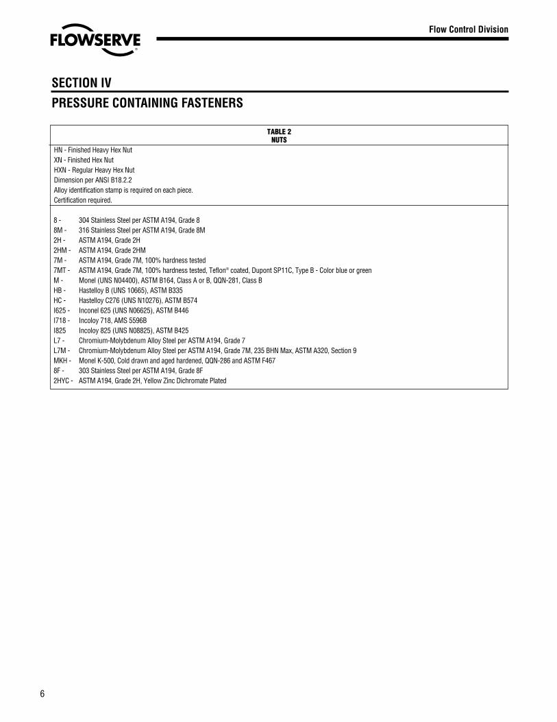
TABLE 2NUTS
HN - Finished Heavy Hex NutXN - Finished Hex NutHXN - Regular Heavy Hex NutDimension per ANSI B18.2.2Alloy identification stamp is required on each piece.Certification required.
8 - 304 Stainless Steel per ASTM A194, Grade 88M - 316 Stainless Steel per ASTM A194, Grade 8M2H - ASTM A194, Grade 2H2HM - ASTM A194, Grade 2HM7M - ASTM A194, Grade 7M, 100% hardness tested7MT - ASTM A194, Grade 7M, 100% hardness tested, Teflon® coated, Dupont SP11C, Type B - Color blue or greenM - Monel (UNS N04400), ASTM B164, Class A or B, QQN-281, Class BHB - Hastelloy B (UNS 10665), ASTM B335HC - Hastelloy C276 (UNS N10276), ASTM B574I625 - Inconel 625 (UNS N06625), ASTM B446I718 - Incoloy 718, AMS 5596BI825 Incoloy 825 (UNS N08825), ASTM B425L7 - Chromium-Molybdenum Alloy Steel per ASTM A194, Grade 7L7M - Chromium-Molybdenum Alloy Steel per ASTM A194, Grade 7M, 235 BHN Max, ASTM A320, Section 9MKH - Monel K-500, Cold drawn and aged hardened, QQN-286 and ASTM F4678F - 303 Stainless Steel per ASTM A194, Grade 8F2HYC - ASTM A194, Grade 2H, Yellow Zinc Dichromate Plated
SECTION IV
PRESSURE CONTAINING FASTENERS
6
Flow Control Division
Section 1.0
1. Apply Durco Seal 1028B to the inside of the tapered borein the body and permit to dry before assembly. RAD-1material is used for nuclear applications.
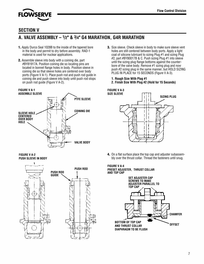
2. Assemble sleeve into body with a coining die, part#BY81917A. Position coining die so locating pins arelocated in bonnet flange holes in body. Position sleeve incoining die so that sleeve holes are centered over bodyports (Figure V A-1). Place push rod and push rod guide incoining die and push sleeve into body until push rod stopson push rod guide (Figure V A-2).
3. Size sleeve. Check sleeve in body to make sure sleeve ventholes are still centered between body ports. Apply a lightcoat of silicone lubricant to sizing Plug #1 and sizing Plug#2, part #BY80017B & C. Push sizing Plug #1 into sleeveuntil the sizing plug flange bottoms against the counter-bore of the valve body. Remove #1 sizing plug and nowpush #2 sizing plug in the same manner, but HOLD SIZINGPLUG IN PLACE for 15 SECONDS (Figure V A-3).
1. Rough Size With Plug #12. Finish Size With Plug #2 (Hold for 15 Seconds)
4. On a flat surface place the top cap and adjuster subassem-bly over the thrust collar. Thread the fasteners until snug.
SECTION V
A. VALVE ASSEMBLY – 1/2" & 3/4" G4 MARATHON, G4R MARATHON
7
SLEEVE HOLECENTEREDOVER BODYHOLE
PUSH RODGUIDE
PUSH ROD
VALVE BODY
COINING DIE
PTFE SLEEVE
FIGURE V A-1ASSEMBLE SLEEVE
FIGURE V A-2PUSH SLEEVE IN BODY
Flow Control Division
Section 1.0
SIZING PLUG
FIGURE V A-3SIZE SLEEVE
SET ADJUSTER CAPSCREWS TO MAKEADJUSTER PARALLEL TOTOP CAP
BOTTOM OF TOP CAP AND THRUST COLLARDIAPHRAGM TO BE FLUSH
CHAMFER
OFFSET
FIGURE V A-4PRESET ADJUSTER, THRUST COLLAR AND TOP CAP

5. The plug stem and dia-phragm guide are to bechecked for nicks orburrs before installingthe diaphragm. Nickson these surfacescould result inscratches on the lipof the diaphragm.Assemble diaphragmover plug stem with theaid of the diaphragmguide, part #BY86272B,and assembly tool, part#BY80019A (FigureV A-5).
6. Using diaphragm guideto protect the o-ringfrom the stem edge,install the first o-ringby “rolling” it with yourfingers over the guideand into the lower stemgroove (Figure V A-6).Install Teflon split ringin a similar mannersuch that it is locatedabove the o-ring insidethe lower groove. SeeFigure V A-7.
7. Install second o-ringand split ring in theupper groove in asimilar manner, exceptthat the diaphragmguide should be raisedso that the lower edgeof the guide does notcontact the lower o-ringassembly. See FigureV A-7. Coat both o-ringassemblies liberallywith Krytox® grease.Remove the guide.
8. Place the thrust collar/diaphragm over theplug stem and gentlymaneuver it over theo-rings onto the PFAdiaphragm. With thethrust collar guide, P/NBY86273B, centeringthe thrust collar assy;force down (with arborpress) the thrust collarguide to seat thethrust collar on thediaphragm. See FigureV A-8. Remove guidefrom plug stem.
9. Place grounding springover plug stem slidingit down to the thrustcollar.
10. Apply a thin, even film of silicone or customer approvedlubricant to the entire surface of the 2° plug taper.
11. Take plug (preassembled with diaphragm, thrust collarand grounding spring) and place it into body. Using asoft head mallet, tap top of plug slightly to seat plug intosleeve taper. The plug at this time will be setting upabove the body counterbore approximately 1/4". Theplug ports should be lined up in an open position.
12. Place the top cap assembly over plug and slide it downuntil it rests on the thrust collar.
13. Assemble four fasteners thru top cap and body. With “U”shaped push plate, part #BY86592A, resting on the topcap (Figure V A-9), force the top cap down (with arborpress or pneumatic clamping arrangement) to seat thetop cap against the valve body counterbore. While holdingthe cap in this position, assemble nuts on underside ofbody flange to a finger tight position against the flange.
NOTE: All fastening torquesare for corrosion free fasten-ers and nuts. Precautionsmust be taken not to exceedrecommended fasteningtorques.
SECTION V
A. VALVE ASSEMBLY – 1/2" & 3/4" G4 MARATHON, G4R MARATHON
8
FIGURE V A-7
FIGURE V A-6
Flow Control Division
Section 1.0
FIGURE V A-5ASSEMBLE DIAPHRAGM ONPLUG
DIAPHRAGMASSEMBLYTOOL
DIAPHRAGM
DIAPHRAGMGUIDE
If damaged theplug taper and 1"in length of stemmust be repolishedto a surface finishof 16AA on thetaper and on stem.
FIGURE V A-8SEAT THRUST COLLAR ONDIAPHRAGM
THRUSTCOLLARGUIDE
THRUSTCOLLAR
FIGURE V A-9ASSEMBLE TOP CAP ASSEMBLYOVER PLUG AND PUSH INTOBODY. APPLY THREAD LOCKINGCOMPOUND.
TOP CAPASSEMBLYPUSH PLATE
9
SECTION V
A. VALVE ASSEMBLY – 1/2" & 3/4" G4 MARATHON, G4R MARATHON
Flow Control Division
Section 1.0
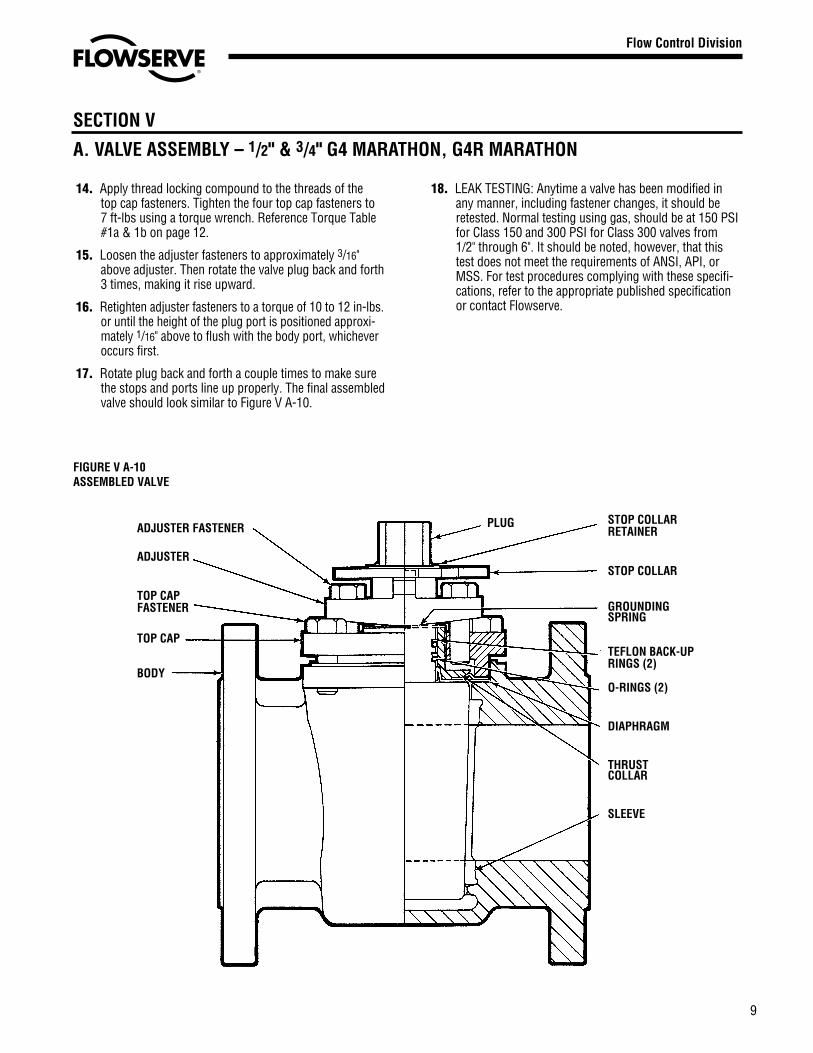
14. Apply thread locking compound to the threads of thetop cap fasteners. Tighten the four top cap fasteners to7 ft-lbs using a torque wrench. Reference Torque Table#1a & 1b on page 12.
15. Loosen the adjuster fasteners to approximately 3/16"above adjuster. Then rotate the valve plug back and forth3 times, making it rise upward.
16. Retighten adjuster fasteners to a torque of 10 to 12 in-lbs.or until the height of the plug port is positioned approxi-mately 1/16" above to flush with the body port, whicheveroccurs first.
17. Rotate plug back and forth a couple times to make surethe stops and ports line up properly. The final assembledvalve should look similar to Figure V A-10.
18. LEAK TESTING: Anytime a valve has been modified inany manner, including fastener changes, it should beretested. Normal testing using gas, should be at 150 PSIfor Class 150 and 300 PSI for Class 300 valves from1/2" through 6". It should be noted, however, that thistest does not meet the requirements of ANSI, API, orMSS. For test procedures complying with these specifi-cations, refer to the appropriate published specificationor contact Flowserve.
FIGURE V A-10ASSEMBLED VALVE
ADJUSTER FASTENER
ADJUSTER
TOP CAPFASTENER
TOP CAP
BODY
TEFLON BACK-UPRINGS (2)
O-RINGS (2)
PLUG STOP COLLARRETAINER
STOP COLLAR
GROUNDINGSPRING
THRUSTCOLLAR
DIAPHRAGM
SLEEVE
10
Flow Control Division
Section 1.0
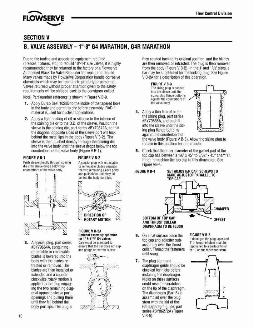
Due to the tooling and associated equipment required(presses, fixtures, etc.) to rebuild 10"-14" size valves, it is highlyrecommended they be returned to the factory or a FlowserveAuthorized Black Tie Valve Rebuilder for repair and rebuild.Many valves made by Flowserve Corporation handle corrosivechemicals which may be injurious to property or personnel.Valves returned without proper attention given to the safetyrequirements will be shipped back to the consignor collect.Note: Part number reference is shown in Figure V B-9.1. Apply Durco Seal 1028B to the inside of the tapered bore
in the body and permit to dry before assembly. RAD-1material is used for nuclear applications.
2. Apply a light coating of oil or silicone to the interior ofthe coining die or to the O.D. of the sleeve. Position thesleeve in the coining die, part series #BY79542A, so thatthe diagonal opposite sides of the sleeve port will lockbehind the metal lips in the body (Figure V B-2). Thesleeve is then pushed directly through the coining dieinto the valve body until the sleeve drops below the topcounterbore of the valve body (Figure V B-1).
FIGURE V B-1 FIGURE V B-2
3. A special plug, part series#BY79664A, containingretractable or removableblades is lowered into thebody with the blades re-tracted or removed. Theblades are then installed orextended and a counterclockwise rotary motion isapplied to the plug engag-ing the two remaining diag-onal opposite sleeve portopenings and pulling themuntil they fall behind thebody port lips. The plug is
then rotated back to its original position, and the bladesare then removed or retracted. The plug is then removedfrom the body (Figure V B-2). In the 1" and 11/2" sizes, abar may be substituted for the locking plug. See FigureV B-2A for a description of this operation.
4. Apply a thin film of oil onthe sizing plug, part series#BY79555A, and push itinto the sleeve until the siz-ing plug flange bottomsagainst the counterbore ofthe valve body (Figure V B-3). Allow the sizing plug toremain in this position for one minute.
5. Check that the inner diameter of the gasket pad of thetop cap has between a 1/6" x 45° to 3/32" x 45° chamfer.If not, remachine the top cap to this dimension. SeeFigure VB-4.
6. On a flat surface place thetop cap and adjuster sub-assembly over the thrustcollar. Thread the fastenersuntil snug.
7. The plug stem anddiaphragm guide should bechecked for nicks beforeinstalling the diaphragm.Nicks on these surfacescould result in scratcheson the lip of the diaphragm.The diaphragm (Part 6) isassembled over the plugstem with the aid of theG4 diaphragm guide, partseries #BY86272A (FigureV B-5).
SECTION V
B. VALVE ASSEMBLY – 1"-8" G4 MARATHON, G4R MARATHON
Push sleeve directly through coiningdie until sleeve drops below topcounterbore of the valve body.
FIGURE V B-3The sizing plug is pushedinto the sleeve until thesizing plug flange bottomsagainst the counterbore ofthe valve body.
FIGURE V B-4
A special plug with retractableor removable blades engagesthe two remaining sleeve portsand pulls them until they fallbehind the body port lips.
FIGURE V B-2AOptional assembly operationfor 1" & 11/2" G4 ValvesCare must be exercised toensure that the bar does not slipand gouge or tear the sleeve.
FIGURE V B-5If damaged the plug taper and1" in length of stem must berepolished to a surface finishof 16 on the taper and stem.
DIRECTION OFROTARY MOTION
CHAMFER
OFFSET
SET ADJUSTER CAP SCREWS TOMAKE ADJUSTER PARALLEL TOTOP CAP
BOTTOM OF TOP CAP AND THRUST COLLARDIAPHRAGM TO BE FLUSH

8. Using the diaphragmguide to protect theo-ring from the stemedge, install the firsto-ring by “rolling” it withyour fingers over theguide and into the lowerstem groove (Figure VB-6). Install Teflon splitring in a similar mannersuch that it is locatedabove the o-ring insidethe lower groove. SeeFigure V B-7.
9. Install second o-ringand split ring in uppergroove in a similarmanner, except that thediaphragm guide shouldbe raised by hand sothat the lower edge ofthe guide does notcontact the lower o-ringassembly. See FigureV B-7. Coat both o-ringassemblies liberallywith Krytox® grease.Remove the guide.
10. Place the thrustcollar/diaphragm overthe plug stem and gentlymaneuver it over theo-rings onto the PFAdiaphragm. The thrustcollar is driven intoplace through the use ofthe thrust collar guide,part series #BY86273A,and an arbor press(Figure V B-8).
11. Place the groundingspring (Part 17) overthe plug stem.
12. Apply a thin, even coatof silicone on the entiresurface of the 2° plugtaper.
13. Place the top cap and adjuster over the plug stem. Placethis subassembly into the valve body. Using an arbor orhydraulic press, push down on the top cap evenly untilthe top cap gasket pad seats firmly against the bodycounterbore. Apply thread locking compound to thethreads of the top cap fasteners. Tighten the top cap
SECTION V
B. VALVE ASSEMBLY – 1"-8" G4 MARATHON, G4R MARATHON
Flow Control Division
Section 1.0
11
fasteners to the torque values found in Torque Table #1a& #2b on page 12.
14. Remove the valve from the arbor press, loosen theadjuster fasteners, and operate the plug several times. Itwill turn hard at first but will then loosen and turn freely.
15. Tighten the adjuster fasteners (Part 12A) until a reason-able turning torque (Ref. Table #2) is obtained. The 8"and larger valves are placed in an oven at 200°F for aminimum of six hours prior to final adjustment with theplug in the open position. After removal from the ovenand valve has cooled, loosen the adjuster fasteners. Turnthe plug several times. Retighten the adjuster fastenersuntil a reasonable plug turning torque is obtained. Theheight of the plug port should be positioned approxi-mately 1/16" above to flush with the body port.
16. Place the stop collar (Part 19A) and retainer on the plugstem. The stop collar should point in the direction of flow.
17. The valve is now ready for test and use.
18. LEAK TESTING: Anytime a valve has been modified inany manner, including fastener changes, it should beretested. Normal testing using gas, should be at 150 PSIfor Class 150 and 300 PSI for Class 300 valves from1/2" through 6". It should be noted, however, that this testdoes not meet the requirements of ANSI, API or MSS.For test procedures complying with these specifications,refer to the appropriate published specification orcontact Flowserve.
FIGURE V B-6
FIGURE V B-7
FIGURE V B-8
THRUSTCOLLARGUIDE ADJUSTER
FASTENERS (12A) PLUG (2)ADJUSTER (12)
GROUNDSPRING (17)
THRUSTCOLLAR(11)
DIAPHRAGM (6)
STOP COLLAR &RETAINER(19A)
TOP CAP FASTENERS (3A)
TEFLON BACK-UPRINGS (20) &
O-RINGS (21)TOPCAP (3)
BODY (1)G4RMARATHON
SLEEVE (5) BODY, G4 MARATHON
FIGURE V B-9ASSEMBLED G4 MARATHON OR G4R MARATHON VALVE
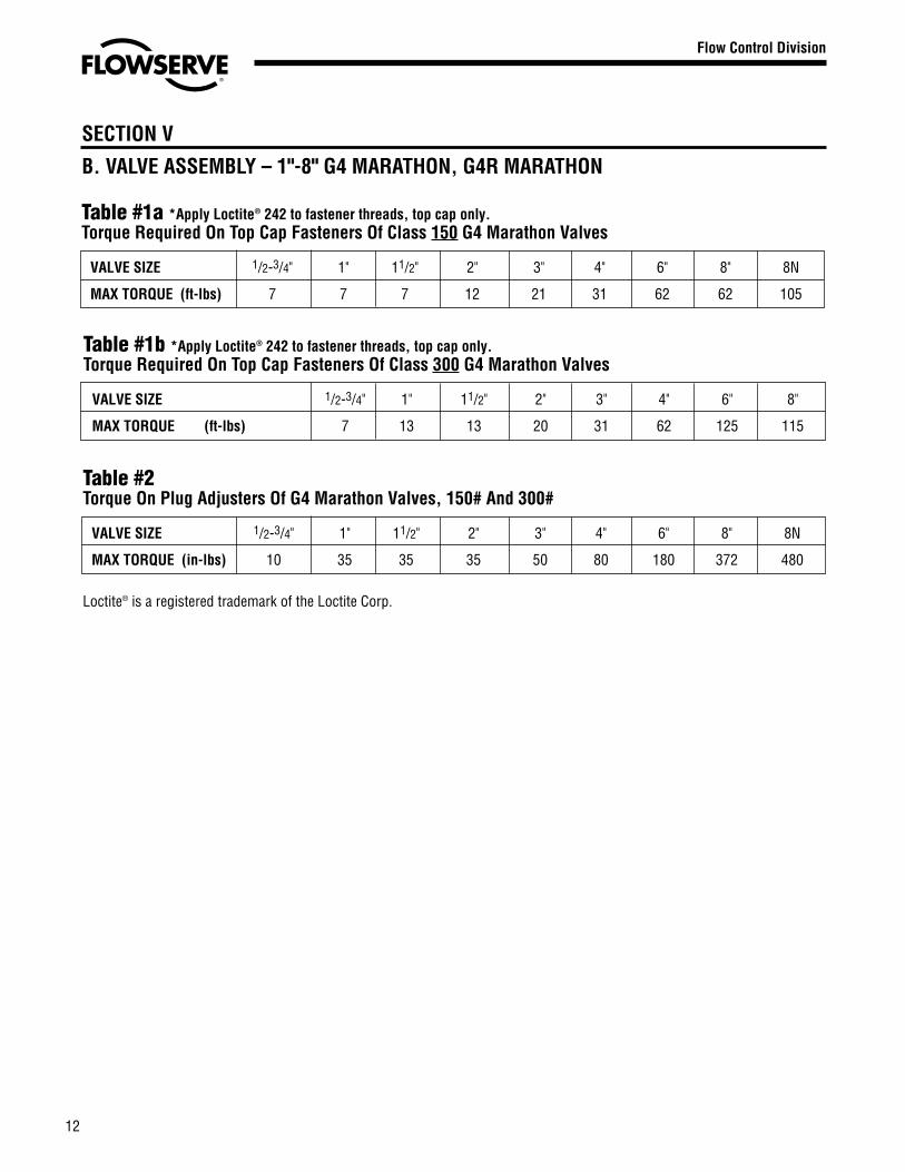
Table #1b *Apply Loctite® 242 to fastener threads, top cap only.Torque Required On Top Cap Fasteners Of Class 300 G4 Marathon Valves
VALVE SIZE 1/2-3/4" 1" 11/2" 2" 3" 4" 6" 8"
MAX TORQUE (ft-lbs) 7 13 13 20 31 62 125 115
SECTION V
B. VALVE ASSEMBLY – 1"-8" G4 MARATHON, G4R MARATHON
12
Flow Control Division
Section 1.0
Table #1a *Apply Loctite® 242 to fastener threads, top cap only.Torque Required On Top Cap Fasteners Of Class 150 G4 Marathon Valves
VALVE SIZE 1/2-3/4" 1" 11/2" 2" 3" 4" 6" 8" 8N
MAX TORQUE (ft-lbs) 7 7 7 12 21 31 62 62 105
Table #2Torque On Plug Adjusters Of G4 Marathon Valves, 150# And 300#
VALVE SIZE 1/2-3/4" 1" 11/2" 2" 3" 4" 6" 8" 8N
MAX TORQUE (in-lbs) 10 35 35 35 50 80 180 372 480
Loctite® is a registered trademark of the Loctite Corp.
13
1/2"-4"1. Normal procedures for field replacement of one piece
sleeves are to be followed for inserting the sleeve,Section V A (1/2" & 3/4"), steps 1-3 or Section V B (1"-8"),steps 1-4.
2. Check that the inner diameter of the gasket pad of thetop cap has between a 1/16" x 45° to 3/32" x 45° cham-fer. If not, remachine the top cap of this dimension. SeeFigure V B-4, page 10.
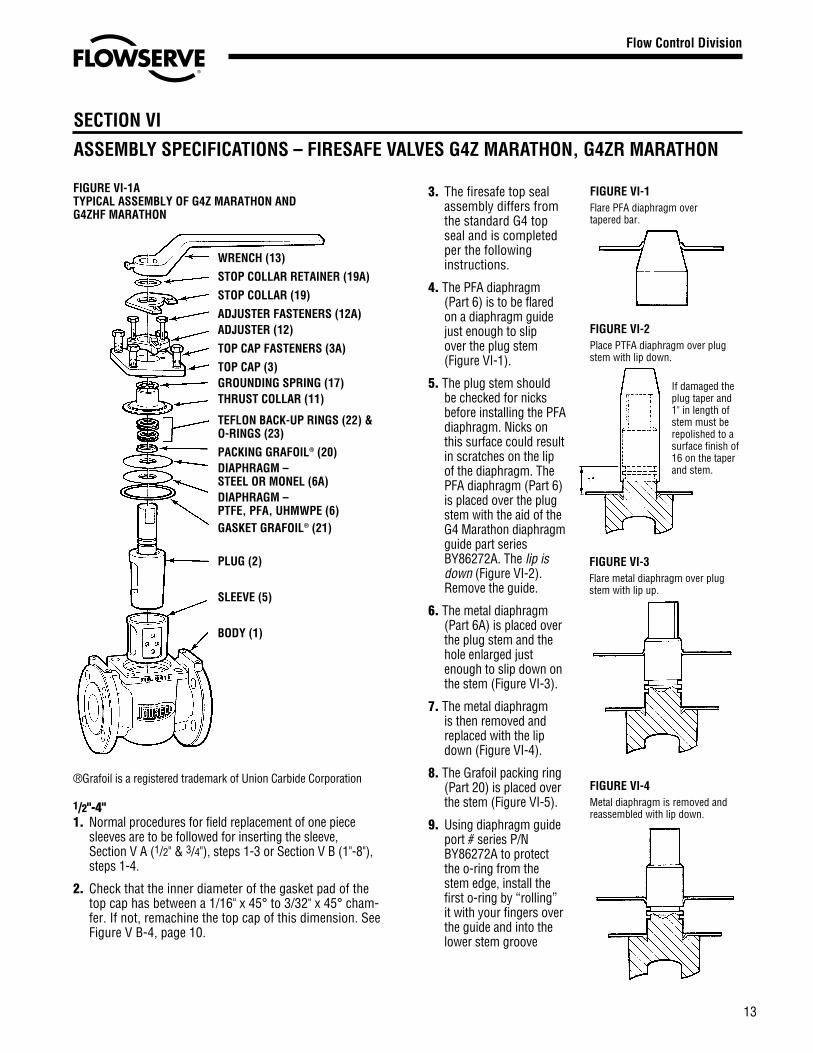
3. The firesafe top sealassembly differs fromthe standard G4 topseal and is completedper the followinginstructions.
4. The PFA diaphragm(Part 6) is to be flaredon a diaphragm guidejust enough to slipover the plug stem(Figure VI-1).
5. The plug stem shouldbe checked for nicksbefore installing the PFAdiaphragm. Nicks onthis surface could resultin scratches on the lipof the diaphragm. ThePFA diaphragm (Part 6)is placed over the plugstem with the aid of theG4 Marathon diaphragmguide part seriesBY86272A. The lip isdown (Figure VI-2).Remove the guide.
6. The metal diaphragm(Part 6A) is placed overthe plug stem and thehole enlarged justenough to slip down onthe stem (Figure VI-3).
7. The metal diaphragmis then removed andreplaced with the lipdown (Figure VI-4).
8. The Grafoil packing ring(Part 20) is placed overthe stem (Figure VI-5).
9. Using diaphragm guideport # series P/NBY86272A to protectthe o-ring from thestem edge, install thefirst o-ring by “rolling”it with your fingers overthe guide and into thelower stem groove
SECTION VI
ASSEMBLY SPECIFICATIONS – FIRESAFE VALVES G4Z MARATHON, G4ZR MARATHON
FIGURE VI-1ATYPICAL ASSEMBLY OF G4Z MARATHON AND G4ZHF MARATHON
®Grafoil is a registered trademark of Union Carbide Corporation
Flow Control Division
Section 1.0
WRENCH (13)
STOP COLLAR RETAINER (19A)
STOP COLLAR (19)
ADJUSTER FASTENERS (12A)ADJUSTER (12)
TOP CAP FASTENERS (3A)
TOP CAP (3)GROUNDING SPRING (17)THRUST COLLAR (11)
TEFLON BACK-UP RINGS (22) &O-RINGS (23)
PACKING GRAFOIL® (20)DIAPHRAGM – STEEL OR MONEL (6A)DIAPHRAGM –PTFE, PFA, UHMWPE (6)GASKET GRAFOIL® (21)
PLUG (2)
SLEEVE (5)
BODY (1)
FIGURE VI-1Flare PFA diaphragm overtapered bar.
If damaged theplug taper and1" in length ofstem must berepolished to asurface finish of16 on the taperand stem.
FIGURE VI-2Place PTFA diaphragm over plugstem with lip down.
FIGURE VI-3Flare metal diaphragm over plugstem with lip up.
FIGURE VI-4Metal diaphragm is removed andreassembled with lip down.

14
Flow Control Division
Section 1.0
(Figure VI-6). InstallTeflon split ring in asimilar manner suchthat it is located abovethe o-ring inside thelower groove. SeeFigure VI-7.
10. Install second o-ringand split ring in uppergroove in a similarmanner, except that thediaphragm guideshould be raised byhand so that the loweredge of the guide doesnot contact the lowero-ring assembly. SeeFigure VI-7. Coat botho-ring assembliesliberally with Krytox®
grease. Remove theguide.
11. Place the thrust collar/diaphragm over theplug stem and gentlymaneuver it over theo-rings onto the Grafoilring. The thrust collar(Part 11) is driven intoplace through the useof the thrust collarguide, part series#BY86273A, and arborpress (Figure VI-8).
12. The entire assemblyis turned over and theGrafoil gasket placed onthe metal diaphragm(Figure VI-9). A smallamount of rubbercement is placed on theGrafoil in several placesto cause it to adhere tothe metal diaphragm.
13. Continue to assemblethe valve per Step 9 ofSection V A for the 1/2"-3/4" size valves or Step11 in Section V B forthe 1"-4".
6"-8"-8"NDue to the tooling andassociated equipmentrequired (presses, fix-tures, etc.) to handle 10"-14" size valves, it is high-ly recommended they bereturned to the factoryfor repair and rebuild.
1. Normal proceduresfor field replacementof one piece sleevesare to be followedfor inserting thesleeve Section V B,steps 1-4.
2. The firesafe top sealassembly differsfrom the standardG4 top seal and iscompleted per thefollowing instruc-tions.
3. The PFA diaphragm(Part 6) is to beflared on thediaphragm guidejust enough to slipover the plug stem(Figure VI-1).
4. The plug stem anddiaphragm guideshould be checkedfor nicks beforeinstalling the PFAdiaphragm. Nicks onthis surface couldresult in scratches on the lip of the diaphragm. The PFAdiaphragm is placed over the diaphragm guide with thelip down (Figure VI-2). Remove the guide.
5. The thrust collar (Part 11) and thrust collar guide, partseries #BY86273A, are to be installed over the plug stemand loaded by an arbor press to flatten the PFA firesafediaphragm. Remove the thrust collar and thrust collarguide.
6. The metal diaphragm (Part 6A) is placed over the plugstem and the hole enlarged just enough to slip down onthe stem (Figure VI-3).
7. A thin coat of silicone oil is applied to the down edge ofthe metal diaphragm. The diaphragm is then placed overthe plug stem with the lip down (Figure VI-4).
SECTION VI
ASSEMBLY SPECIFICATIONS – FIRESAFE VALVES G4Z, G4ZHF, G4ZR
FIGURE VI-5Grafoil packing ring placed over stem.
FIGURE VI-6O-ring placed over stem.
FIGURE VI-7
FIGURE VI-8Packing and thrust collar driveninto place.
GASKET
FIGURE VI-9Grafoil gasket placed on metaldiaphragm using a bonding material.
15
8. The Grafoil packing ring (Part 20) is placed over the stem(Figure VI-5).
9. Using the diaphragm guide P/N BY86272A to protect theo-ring from the stem edge, install the first o-ring by“rolling” it with your fingers over the guide and into thelower stem groove (Figure VI-6). Install Teflon split ring ina similar manner such that it is located above the o-ringinside the lower groove. See Figure VI-7.
10. Install second o-ring and split ring in upper groove in asimilar manner, except that the diaphragm guide shouldbe raised by hand so that the lower edge of the guidedoes not contact the lower o-ring assembly. See FigureVI-7. Coat both o-ring assemblies liberally with Krytoxgrease.
11. Place the thrust collar/diaphragm over the plug stem andgently maneuver it over the o-rings onto the Grafoil ring.The thrust collar (Part 11) is then driven into placethrough the use of the thrust collar guide part # seriesBY86273A and arbor press (Figure VI-8).
12. The Grafoil top cap gasket (Part 21) is to be installed withthe tapered or small edge diameter down or placedagainst the valve counterbore. The plug is pushed downuntil it is flush with the bottom of the body port in orderto check the diaphragm fit inside the Grafoil gasket forclearance. The PFA diaphragm must not ride on theGrafoil gasket but should fit just inside the Grafoil.
13. The adjuster fasteners must be preset per Section VB-6.Check that the inner diameter of the gasket pad of the topcap has between a 1/16" x 45° to 3/32" x 45° chamfer. Ifnot, remachine the top cap to this dimension. The top cap(bonnet) (Part 3) and thrust collar assembly is installedand the plug is pushed down in the open position againuntil the bottom of the port is flush and the top capbottoms firmly on body counterbore. The top cap mustbe checked before installation to ensure there is nochamfer on outside edge of the cap.
14. The top cap is visually located to be evenly spaced insidethe body counterbore. The side of the top cap compres-sion flange is equally spaced with the side wall of thebody counterbore. Fasteners should be installed andtightened to 5 ft-lb torque to prevent movement of thecap during initial torquing. Push down on the top capevenly until the top cap gasket pad seats firmly againstthe body counterbore.
15. Once it has been determined that the gaskets fit properly,continue to tighten the top cap fasteners in 50 ft-lb incre-ments in a crisscross fashion to the levels found in Table#1a & 1b, page 12.
Note: All fastening torques are for Locktite® coated,corrosion free fasteners and nuts. Extreme care must betaken to prevent overstressing fasteners and subsequent
valve parts by tightening in excess of industry standardsfor appropriate size and alloy fasteners. Ref. Torque Table#1a & 1b.
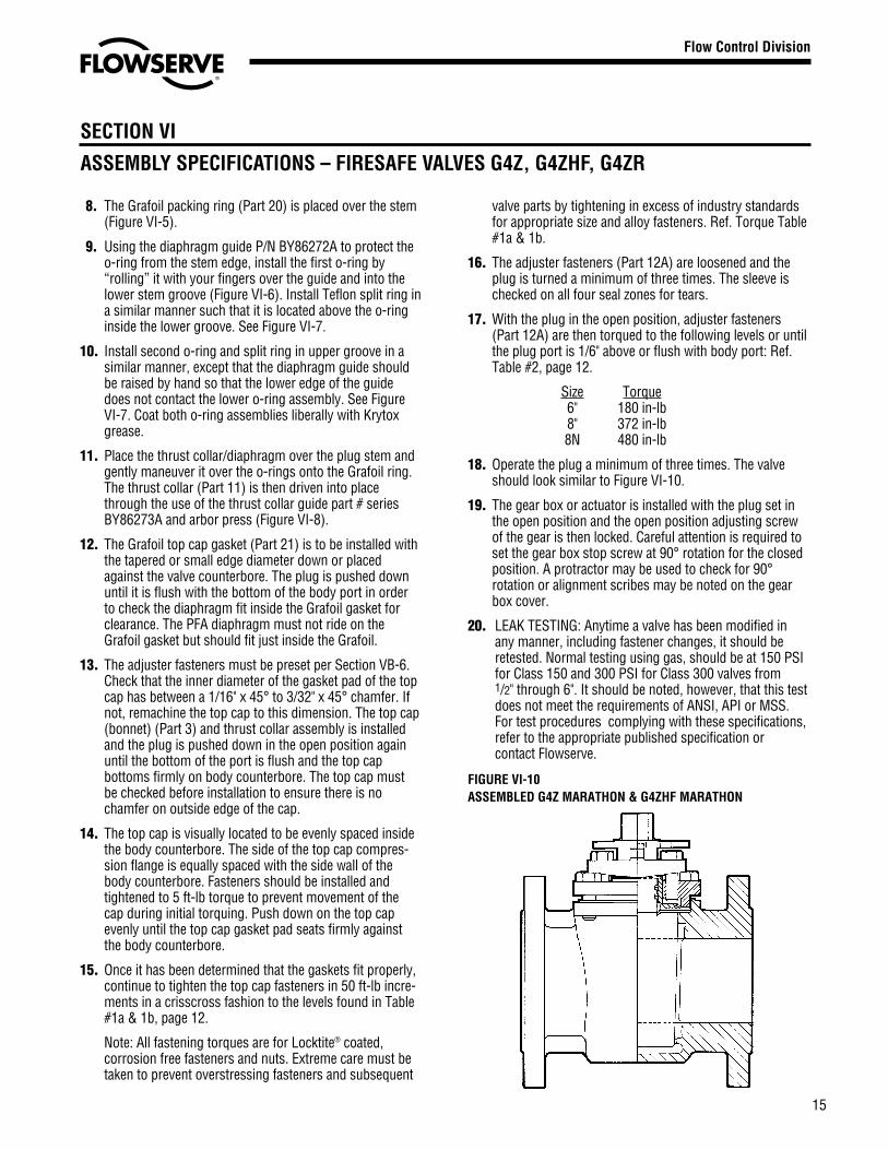
16. The adjuster fasteners (Part 12A) are loosened and theplug is turned a minimum of three times. The sleeve ischecked on all four seal zones for tears.
17. With the plug in the open position, adjuster fasteners(Part 12A) are then torqued to the following levels or untilthe plug port is 1/6" above or flush with body port: Ref.Table #2, page 12.
Size Torque6" 180 in-lb8" 372 in-lb8N 480 in-lb
18. Operate the plug a minimum of three times. The valveshould look similar to Figure VI-10.
19. The gear box or actuator is installed with the plug set inthe open position and the open position adjusting screwof the gear is then locked. Careful attention is required toset the gear box stop screw at 90° rotation for the closedposition. A protractor may be used to check for 90°rotation or alignment scribes may be noted on the gearbox cover.
20. LEAK TESTING: Anytime a valve has been modified inany manner, including fastener changes, it should beretested. Normal testing using gas, should be at 150 PSIfor Class 150 and 300 PSI for Class 300 valves from1/2" through 6". It should be noted, however, that this testdoes not meet the requirements of ANSI, API or MSS.For test procedures complying with these specifications,refer to the appropriate published specification orcontact Flowserve.
SECTION VI
ASSEMBLY SPECIFICATIONS – FIRESAFE VALVES G4Z, G4ZHF, G4ZR
Flow Control Division
Section 1.0
FIGURE VI-10ASSEMBLED G4Z MARATHON & G4ZHF MARATHON
Or Consult Your Local Stocking Distributor
A T O M A C
Printed in U.S.A.January 2002
© Flowserve Corporation
Flowserve Ahaus GmbHVon Braun Straße 19aD-48683 AhausGermanyPhone: +49 2561 686-0Fax: +49 2561 686-39
Flowserve Pte. Ltd.12 Tuas Avenue 20Republic of Singapore 638824Phone: 65-862-3332Fax: 65 862 2800
SECTION VII
RECOMMENDED SPARE PARTS
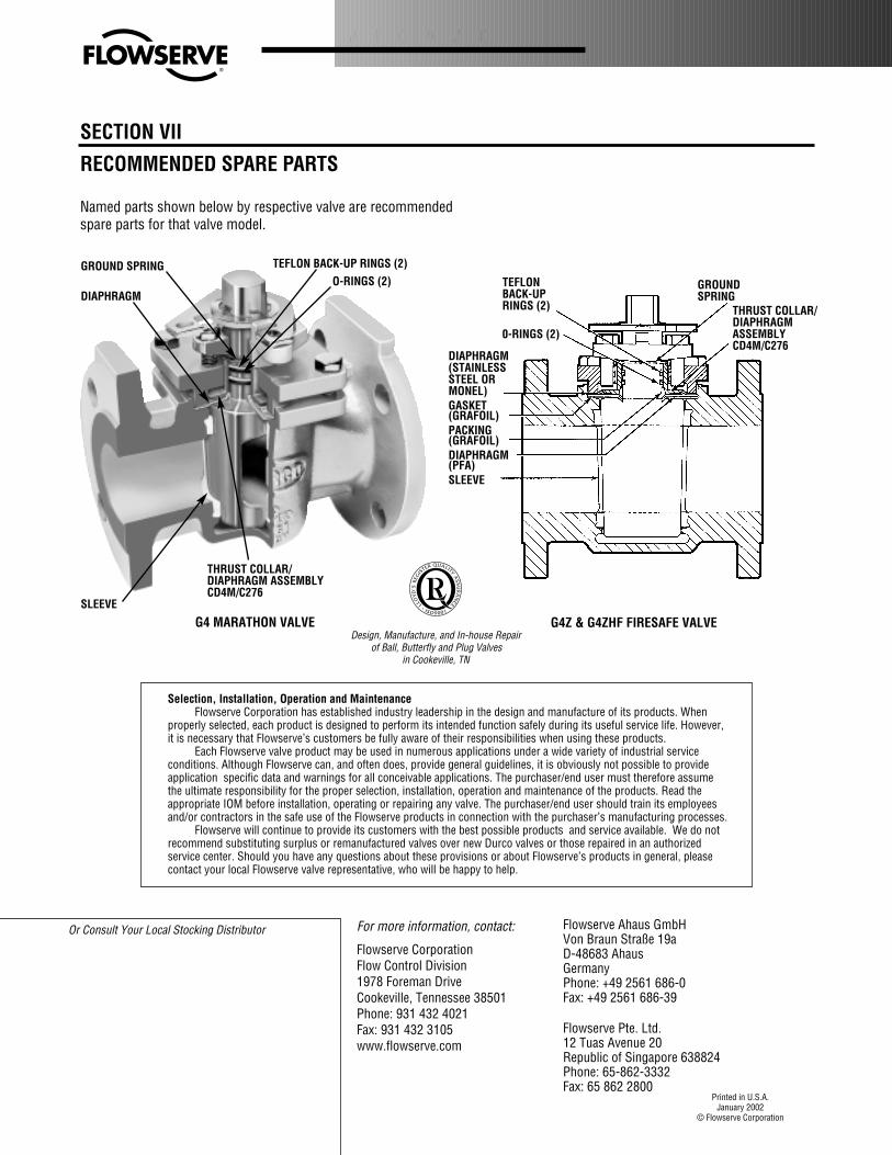
Named parts shown below by respective valve are recommendedspare parts for that valve model.
Design, Manufacture, and In-house Repairof Ball, Butterfly and Plug Valves
in Cookeville, TN
GROUND SPRING
DIAPHRAGM
SLEEVE
G4 MARATHON VALVE
GROUNDSPRING
TEFLONBACK-UPRINGS (2)
0-RINGS (2)
THRUST COLLAR/DIAPHRAGMASSEMBLYCD4M/C276
G4Z & G4ZHF FIRESAFE VALVE
Selection, Installation, Operation and MaintenanceFlowserve Corporation has established industry leadership in the design and manufacture of its products. When
properly selected, each product is designed to perform its intended function safely during its useful service life. However,it is necessary that Flowserve’s customers be fully aware of their responsibilities when using these products.
Each Flowserve valve product may be used in numerous applications under a wide variety of industrial serviceconditions. Although Flowserve can, and often does, provide general guidelines, it is obviously not possible to provideapplication specific data and warnings for all conceivable applications. The purchaser/end user must therefore assumethe ultimate responsibility for the proper selection, installation, operation and maintenance of the products. Read theappropriate IOM before installation, operating or repairing any valve. The purchaser/end user should train its employeesand/or contractors in the safe use of the Flowserve products in connection with the purchaser’s manufacturing processes.
Flowserve will continue to provide its customers with the best possible products and service available. We do notrecommend substituting surplus or remanufactured valves over new Durco valves or those repaired in an authorizedservice center. Should you have any questions about these provisions or about Flowserve’s products in general, pleasecontact your local Flowserve valve representative, who will be happy to help.
For more information, contact:
Flowserve CorporationFlow Control Division1978 Foreman DriveCookeville, Tennessee 38501Phone: 931 432 4021Fax: 931 432 3105www.flowserve.com
DIAPHRAGM(STAINLESSSTEEL ORMONEL)GASKET(GRAFOIL)PACKING(GRAFOIL)DIAPHRAGM(PFA)SLEEVE
TEFLON BACK-UP RINGS (2)O-RINGS (2)
THRUST COLLAR/DIAPHRAGM ASSEMBLYCD4M/C276


![VDR G4[e] S-VDR G4[e] - interschalt.com · Modular and scalable design ... VDR G4[e] S-VDR G4[e] Worldwide Network ... VDR Requirements S-VDR G4[e] S-VDR Requirements Overview](https://img.pdfslide.net/doc/110x75/5af3f3967f8b9a95468d4730/vdr-g4e-s-vdr-g4e-and-scalable-design-vdr-g4e-s-vdr-g4e-worldwide.jpg)