Embed Size (px)
Citation preview
®
G400/G2000Appliance
Quick Start Guide

Internet Security Systems, Inc.6303 Barfield RoadAtlanta, Georgia 30328-4233United States(404) 236-2600http://www.iss.net
© Internet Security Systems, Inc. 2003-2005. All rights reserved worldwide. Customers may make reasonable numbers of copies of this publication for internal use only. This publication may not otherwise be copied or reproduced, in whole or in part, by any other person or entity without the express prior written consent of Internet Security Systems, Inc.
Patent pending.
Internet Security Systems, System Scanner, Wireless Scanner, SiteProtector, Proventia, ADDME, AlertCon, ActiveAlert, FireCell, FlexCheck, Secure Steps, SecurePartner, SecureU, and X-Press Update are trademarks and service marks, and the Internet Security Systems logo, X-Force, SAFEsuite, Internet Scanner, Database Scanner, Online Scanner, and RealSecure registered trademarks, of Internet Security Systems, Inc. Network ICE, the Network ICE logo, and ICEpac are trademarks, BlackICE a licensed trademark, and ICEcap a registered trademark, of Network ICE Corporation, a wholly owned subsidiary of Internet Security Systems, Inc. SilentRunner is a registered trademark of Raytheon Company. Acrobat and Adobe are registered trademarks of Adobe Systems Incorporated. Certicom is a trademark and Security Builder is a registered trademark of Certicom Corp. Check Point, FireWall-1, OPSEC, Provider-1, and VPN-1 are registered trademarks of Check Point Software Technologies Ltd. or its affiliates. Cisco and Cisco IOS are registered trademarks of Cisco Systems, Inc. HP-UX and OpenView are registered trademarks of Hewlett-Packard Company. IBM and AIX are registered trademarks of IBM Corporation. InstallShield is a registered trademark and service mark of InstallShield Software Corporation in the United States and/or other countries. Intel and Pentium are registered trademarks of Intel. Lucent is a trademark of Lucent Technologies, Inc. ActiveX, Microsoft, Windows, and Windows NT are either registered trademarks or trademarks of Microsoft Corporation. Net8, Oracle, Oracle8, SQL*Loader, and SQL*Plus are trademarks or registered trademarks of Oracle Corporation. Seagate Crystal Reports, Seagate Info, Seagate, Seagate Software, and the Seagate logo are trademarks or registered trademarks of Seagate Software Holdings, Inc. and/or Seagate Technology, Inc. Secure Shell and SSH are trademarks or registered trademarks of SSH Communications Security. iplanet, Sun, Sun Microsystems, the Sun Logo, Netra, SHIELD, Solaris, SPARC, and UltraSPARC are trademarks or registered trademarks of Sun Microsystems, Inc. in the United States and other countries. All SPARC trademarks are used under license and are trademarks or registered trademarks of SPARC International, Inc. in the United States and other countries. Adaptive Server, SQL, SQL Server, and Sybase are trademarks of Sybase, Inc., its affiliates and licensers. Tivoli is a registered trademark of Tivoli Systems Inc. UNIX is a registered trademark in the United States and other countries, licensed exclusively through X/Open Company, Ltd. All other trademarks are the property of their respective owners and are used here in an editorial context without intent of infringement. Specifications are subject to change without notice.
© Intel Corporation, 2002.
Disclaimer: The information contained in this document may change without notice, and may have been altered or changed if you have received it from a source other than ISS or the X-Force. Use of this information constitutes acceptance for use in an “AS IS” condition, without warranties of any kind, and any use of this information is at the user’s own risk. ISS and the X-Force disclaim all warranties, either expressed or implied, including the warranties of merchantability and fitness for a particular purpose. In no event shall ISS or the X-Force be liable for any damages whatsoever, including direct, indirect, incidental, consequential or special damages, arising from the use or dissemination hereof, even if ISS or the X-Force has been advised of the possibility of such damages. Some states do not allow the exclusion or limitation of liability for consequential or incidental damages, so the foregoing limitation may not apply.
Reference herein to any specific commercial products, process, or service by trade name, trademark, manufacturer, or otherwise, does not necessarily constitute or imply its endorsement, recommendation, or favoring by Internet Security Systems, Inc. The views and opinions of authors expressed herein do not necessarily state or reflect those of Internet Security Systems, Inc., and shall not be used for advertising or product endorsement purposes.
Links and addresses to Internet resources are inspected thoroughly prior to release, but the ever-changing nature of the Internet prevents Internet Security Systems from guaranteeing the content or existence of the resource. When possible, the reference contains alternate sites or keywords that could be used to acquire the information by other methods. If you find a broken or inappropriate link, please send an email with the topic name, link, and its behavior to [email protected].
Document part number: DOC-QSG-PROVIPAG-004-A
March 25, 2005
Contents
Preface. . . . . . . . . . . . . . . . . . . . . . . . . . . . . . . . . . . . . . . . . . . . . . . . . . . . . . . . vOverview . . . . . . . . . . . . . . . . . . . . . . . . . . . . . . . . . . . . . . . . . . . . . . . . . . . . . . . vAbout the Proventia Intrusion Prevention Appliances . . . . . . . . . . . . . . . . . . . . . . . . . viHow to Use the Documentation . . . . . . . . . . . . . . . . . . . . . . . . . . . . . . . . . . . . . . . viii
Chapter 1: Connecting the ApplianceOverview . . . . . . . . . . . . . . . . . . . . . . . . . . . . . . . . . . . . . . . . . . . . . . . . . . . . . . 1G400/G2000 Front and Back Panels . . . . . . . . . . . . . . . . . . . . . . . . . . . . . . . . . . 2The External Bypass Unit . . . . . . . . . . . . . . . . . . . . . . . . . . . . . . . . . . . . . . . . . . . 7Connecting the Bypass Unit to the Appliance . . . . . . . . . . . . . . . . . . . . . . . . . . . . . . 9High Availability Port Connectivity . . . . . . . . . . . . . . . . . . . . . . . . . . . . . . . . . . . . . 12Connecting the Cables and Starting the Appliance . . . . . . . . . . . . . . . . . . . . . . . . . 15Standard Inline Deployment Scenarios . . . . . . . . . . . . . . . . . . . . . . . . . . . . . . . . . 17High Availability Deployment. . . . . . . . . . . . . . . . . . . . . . . . . . . . . . . . . . . . . . . . . 20
Chapter 2: Configuring the ApplianceOverview . . . . . . . . . . . . . . . . . . . . . . . . . . . . . . . . . . . . . . . . . . . . . . . . . . . . . 23Before You Begin. . . . . . . . . . . . . . . . . . . . . . . . . . . . . . . . . . . . . . . . . . . . . . . . 24Logging On and Configuring the G400 or G2000 Appliance . . . . . . . . . . . . . . . . . . . 26Accessing Proventia Manager for G400 and G2000 . . . . . . . . . . . . . . . . . . . . . . . 30Connecting to SiteProtector . . . . . . . . . . . . . . . . . . . . . . . . . . . . . . . . . . . . . . . . 33Configuring SiteProtector Management. . . . . . . . . . . . . . . . . . . . . . . . . . . . . . . . . 36Configuring Inline High Availability . . . . . . . . . . . . . . . . . . . . . . . . . . . . . . . . . . . . . 38
Chapter 3: Reinstalling the ApplianceOverview . . . . . . . . . . . . . . . . . . . . . . . . . . . . . . . . . . . . . . . . . . . . . . . . . . . . . 41Reinstallation Requirements . . . . . . . . . . . . . . . . . . . . . . . . . . . . . . . . . . . . . . . . 42Reinstalling the Appliance . . . . . . . . . . . . . . . . . . . . . . . . . . . . . . . . . . . . . . . . . . 43Getting Technical Support . . . . . . . . . . . . . . . . . . . . . . . . . . . . . . . . . . . . . . . . . . 44
Index . . . . . . . . . . . . . . . . . . . . . . . . . . . . . . . . . . . . . . . . . . . . . . . . . . . . . . . . 47
iiiProventia G400/G2000 Appliance Quick Start Guide

Contents
iv
Preface
Overview
Introduction This Quick Start Guide contains the procedures for connecting and configuring the Proventia G400 and G2000 Intrusion Prevention Appliances.
Scope This guide supports the Proventia G400 and G2000 appliance firmware release 1.1. It includes information about the appliance hardware, procedures for initial setup, and information about using the appliances for inline high availability.
Audience This guide is intended for network security system administrators who are responsible for configuring and managing the Proventia G400 and G2000 appliances. A fundamental knowledge of network security policies and IP network configuration is helpful.
For information about other G models, see the Proventia G100/G200/G1000/G1200 Quick Start Guide.
What’s new in this guide
This release contains new information about using the G400 or G2000 appliances in high availability network environment.
vProventia G400/G2000 Appliance Quick Start Guide
Preface
About the Proventia Intrusion Prevention Appliances
Introduction The Proventia G400 and G2000 model Intrusion Prevention Appliances are inline intrusion prevention systems (IPS) that automatically block malicious attacks while preserving network bandwidth and availability.
Capabilities The appliances offer the following capabilities:
● three modes of operation, configured at the port level
■ inline protection
■ inline simulation
■ passive monitor
● high availability (HA) modes (cannot be configured at the port level)
■ normal mode
■ HA simulation mode
■ HA protection mode
● firewall rules
● quarantine rules
● blocking
● SNMP (Simple Network Management Protocol)
Note: You can use either SiteProtector or Proventia Manager to manage the G400 or G2000 models.
Reference: For information about high availability with G appliances, see“High Availability Deployment” on page 20 and “Configuring Inline High Availability” on page 38.
Important: SiteProtector must be updated to the latest Database Service Release prior to installing the Proventia G400/G2000 Firmware 1.1.
Proventia Setup utility
The Proventia Setup utility is your local command line configuration interface. Use this tool to initially configure your appliance settings. See “Connecting the Cables and Starting the Appliance” on page 15.
vi
About the Proventia Intrusion Prevention Appliances
Proventia Manager Proventia Manager offers a Web-based interface software for local appliance management. Proventia Manager provides local management of the following functions:
● monitor the status of the appliance
● configure operation modes
● configure high availability
● configure firewall settings
● manage appliance settings and activities
● review event details
Reference: For more information, see “Accessing Proventia Manager for G400 and G2000” on page 30.
viiProventia G400/G2000 Appliance Quick Start Guide
Preface
How to Use the Documentation
Using this guide Use the Proventia G400/G2000 Appliance Quick Start Guide to install and configure Proventia G400 and G2000 model Intrusion Prevention Appliances. Use the Proventia G100/G200/G1000/G1200 Appliance Quick Start Guide to install and configure other Proventia G models.
Related publications For the latest available appliance documentation, refer to the Help and the Readme files associated with each appliance release.
Additional documentation includes the following:
● Proventia G400/G2000 Appliances User Guide
● SiteProtector Installation Guide
● SiteProtector User Guide for Security Managers
● SiteProtector Technical Reference Guide
● SiteProtector Best Practices Guide
These documents are available on the ISS Web site at the following location: http://www.iss.net/support/documentation/
viii
Chapter 1
Connecting the Appliance
Overview
Introduction This chapter contains diagrams and connection procedures for the G400 and G2000 Intrusion Prevention Appliances, and includes information about using an external bypass unit. Information about connecting the G appliances for use in a high availability environment is also provided.
Rack mount instructions
Rack mount kit instructions are included in your appliance box as follows:
● tool-less slide rail kit (G2000C, G2000F and G2000CF models only)
● mid-mount kit (for 1U or 2U appliances)
Box Contents The Proventia G appliance packaging includes the following:
● AC or DC power cable(s)
● slide rail kit (option 1)
● mid-mount rack kit (option 2)
● appliance recovery CD
● RJ-45 to DB9 serial cable
● strain relief
● warranty statement
● bezel cover with keys
● mouse/keyboard Y-cable
● crossover connector and patch cable (copper only)
1Proventia G400/G2000 Appliance Quick Start Guide
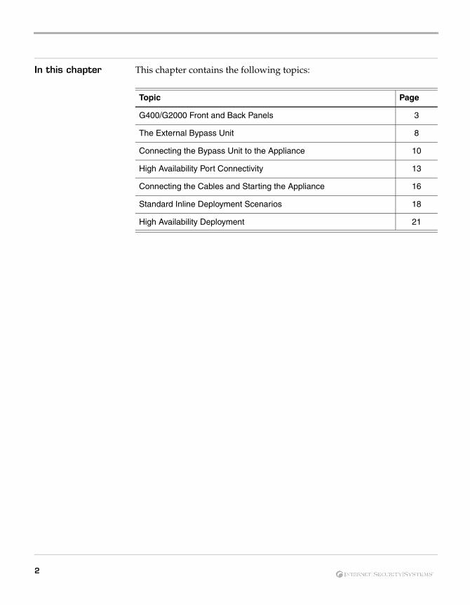
In this chapter This chapter contains the following topics:
Topic Page
G400/G2000 Front and Back Panels 3
The External Bypass Unit 8
Connecting the Bypass Unit to the Appliance 10
High Availability Port Connectivity 13
Connecting the Cables and Starting the Appliance 16
Standard Inline Deployment Scenarios 18
High Availability Deployment 21
2
G400/G2000 Front and Back Panels
G400/G2000 Front and Back Panels
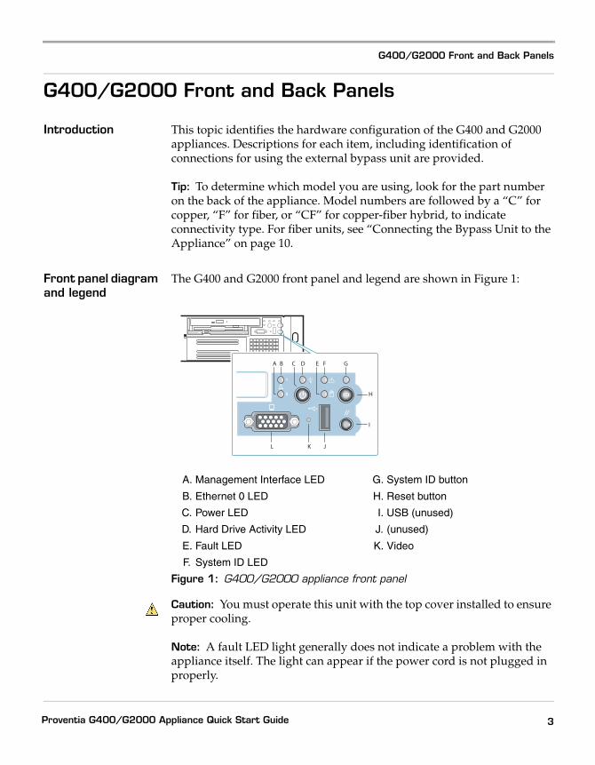
Introduction This topic identifies the hardware configuration of the G400 and G2000 appliances. Descriptions for each item, including identification of connections for using the external bypass unit are provided.
Tip: To determine which model you are using, look for the part number on the back of the appliance. Model numbers are followed by a “C” for copper, “F” for fiber, or “CF” for copper-fiber hybrid, to indicate connectivity type. For fiber units, see “Connecting the Bypass Unit to the Appliance” on page 10.
Front panel diagram and legend
The G400 and G2000 front panel and legend are shown in Figure 1:
Caution: You must operate this unit with the top cover installed to ensure proper cooling.
Note: A fault LED light generally does not indicate a problem with the appliance itself. The light can appear if the power cord is not plugged in properly.
A. Management Interface LED
B. Ethernet 0 LED
C. Power LED
D. Hard Drive Activity LED
E. Fault LED
F. System ID LED
G. System ID button
H. Reset button
I. USB (unused)
J. (unused)
K. Video
Figure 1: G400/G2000 appliance front panel
L JK
H
I
BA F GEDC
3Proventia G400/G2000 Appliance Quick Start Guide
G400F back panel diagram
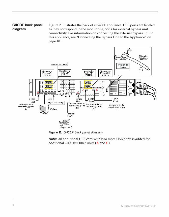
Figure 2 illustrates the back of a G400F appliance. USB ports are labeled as they correspond to the monitoring ports for external bypass unit connectivity. For information on connecting the external bypass unit to this appliance, see “Connecting the Bypass Unit to the Appliance” on page 10.
Figure 2: G400F back panel diagram
Note: an additional USB card with two more USB ports is added for additional G400 full fiber units (A and C)
4
G400/G2000 Front and Back Panels
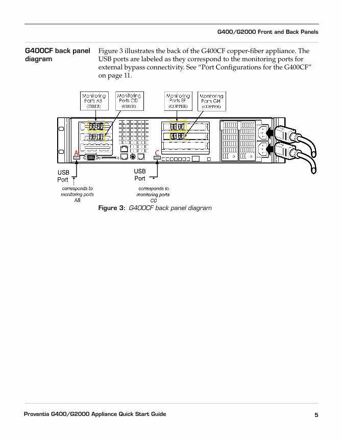
G400CF back panel diagram
Figure 3 illustrates the back of the G400CF copper-fiber appliance. The USB ports are labeled as they correspond to the monitoring ports for external bypass connectivity. See “Port Configurations for the G400CF” on page 11.
Figure 3: G400CF back panel diagram
5Proventia G400/G2000 Appliance Quick Start Guide
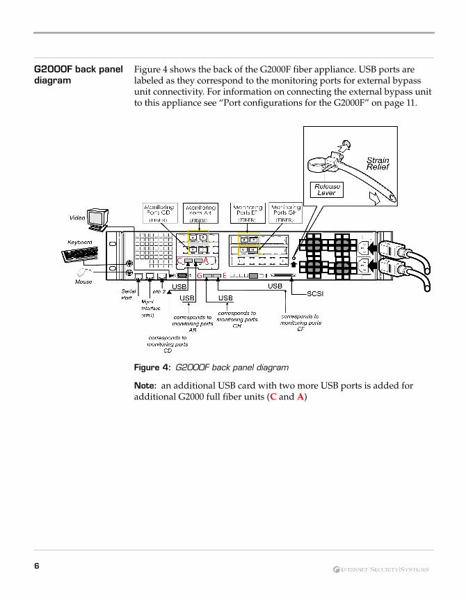
G2000F back panel diagram
Figure 4 shows the back of the G2000F fiber appliance. USB ports are labeled as they correspond to the monitoring ports for external bypass unit connectivity. For information on connecting the external bypass unit to this appliance see “Port configurations for the G2000F” on page 11.
Figure 4: G2000F back panel diagram
Note: an additional USB card with two more USB ports is added for additional G2000 full fiber units (C and A)
6
G400/G2000 Front and Back Panels
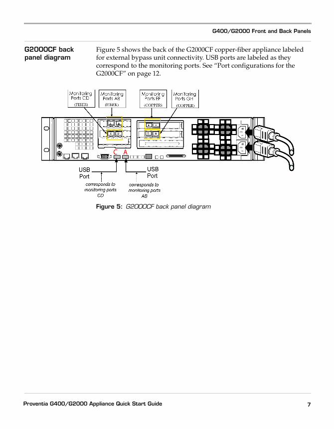
G2000CF back panel diagram
Figure 5 shows the back of the G2000CF copper-fiber appliance labeled for external bypass unit connectivity. USB ports are labeled as they correspond to the monitoring ports. See “Port configurations for the G2000CF” on page 12.
Figure 5: G2000CF back panel diagram
7Proventia G400/G2000 Appliance Quick Start Guide
The External Bypass Unit
Introduction The external bypass unit monitors the appliance and ensures that network traffic continues to flow if the appliance fails or loses power. The full fiber and copper-fiber hybrid G400F, G400CF and G2000F and G2000CF model appliances use the external bypass unit.
Important: Make sure your appliance is turned off before making any connections to the bypass unit. Follow the connection specifications exactly described in this topic.
Items in the bypass unit kit
The single and dual bypass units come with the items shown in Table 1:
Table 1: Items included with the bypass units
Required network cables
You must have two additional fiber cables to connect a single bypass unit and four additional fiber cables to connect a dual bypass unit to a network switch or router. These cables do not come supplied with the units.
Single Bypass Unit Dual Bypass Unit
One USB cable Two USB cables
Two fiber cables Four fiber cables
Bezel cover with keys Bezel cover with keys
8
The External Bypass Unit
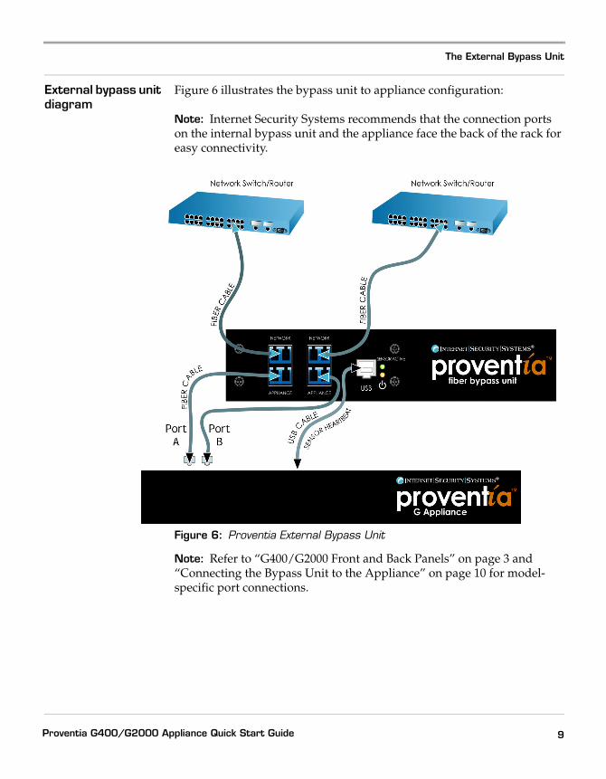
External bypass unit diagram
Figure 6 illustrates the bypass unit to appliance configuration:
Note: Internet Security Systems recommends that the connection ports on the internal bypass unit and the appliance face the back of the rack for easy connectivity.
Figure 6: Proventia External Bypass Unit
Note: Refer to “G400/G2000 Front and Back Panels” on page 3 and “Connecting the Bypass Unit to the Appliance” on page 10 for model-specific port connections.
9Proventia G400/G2000 Appliance Quick Start Guide
Connecting the Bypass Unit to the Appliance
Introduction Important: Turn the appliance OFF before you connect the G400 or G2000 appliance to the external bypass unit.
For each USB port to be correctly associated with the corresponding pair of monitoring ports, the USB cables must be connected before the appliance is turned on. If you connect or disconnect any USB cables while the appliance is on, you must restart the appliance. Each USB port should be connected as described in the following topics.
Note: If you are unsure whether your appliance is full fiber or copper, refer to the sticker on the back of the appliance.
Caution: If you disconnect or change USB port connections, or replace interface cards after the appliance and bypass unit are initialized, the system may renumber the USB ports. ISS recommends that you set up the connections as described in this topic. If you need to adjust your ports, you must turn off the appliance, and then reconfigure your port settings.
Connecting the cables
To connect the bypass unit to the appliance:
1. Connect the fiber cables from the network ports on the bypass unit to your network switch and routers.
2. Verify that traffic is flowing between the network and the appliance.
Note: If you can ping the appliance, traffic is flowing between the network and the appliance.
3. Connect the fiber cables (included with the appliance) from the ports on bypass unit to the corresponding ports on the back of the appliance, as shown in Figure 6 on page 9.
4. Connect the USB cable from the USB port on the bypass unit to the correct USB port(s) on the back of the appliance. Depending on your appliance model, see Figure 2 through Figure 5 for specific connections.
Connecting the G400 appliances
This topic describes how to connect an external bypass unit to the G400F and G400CF appliances. Refer to Figure 2 on page 4 and Figure 3 on page 5 for back panel diagrams corresponding to the following tables.
10
Connecting the Bypass Unit to the Appliance
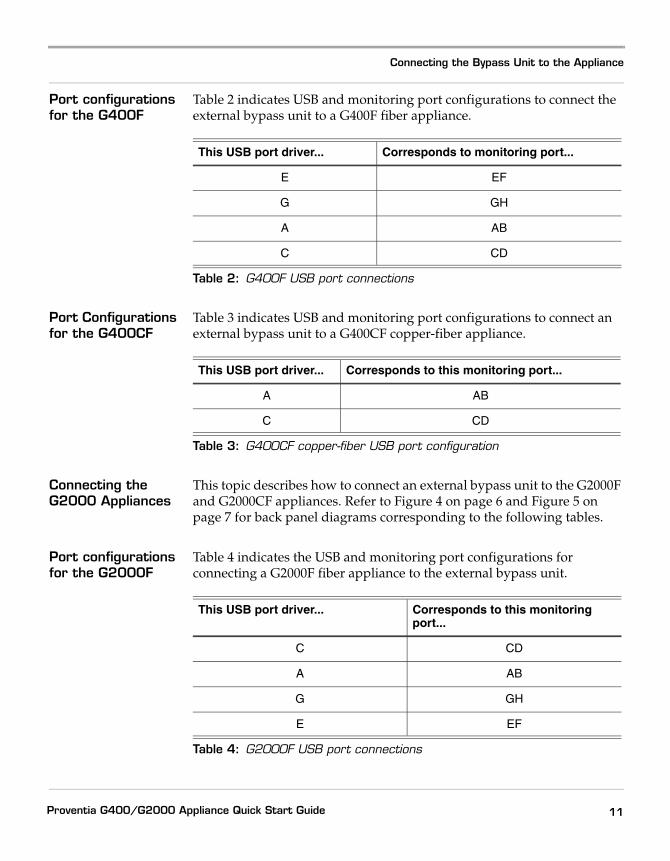
Port configurations for the G400F
Table 2 indicates USB and monitoring port configurations to connect the external bypass unit to a G400F fiber appliance.
Port Configurations for the G400CF
Table 3 indicates USB and monitoring port configurations to connect an external bypass unit to a G400CF copper-fiber appliance.
Connecting the G2000 Appliances
This topic describes how to connect an external bypass unit to the G2000F and G2000CF appliances. Refer to Figure 4 on page 6 and Figure 5 on page 7 for back panel diagrams corresponding to the following tables.
Port configurations for the G2000F
Table 4 indicates the USB and monitoring port configurations for connecting a G2000F fiber appliance to the external bypass unit.
This USB port driver... Corresponds to monitoring port...
E EF
G GH
A AB
C CD
Table 2: G400F USB port connections
This USB port driver... Corresponds to this monitoring port...
A AB
C CD
Table 3: G400CF copper-fiber USB port configuration
This USB port driver... Corresponds to this monitoring port...
C CD
A AB
G GH
E EF
Table 4: G2000F USB port connections
11Proventia G400/G2000 Appliance Quick Start Guide
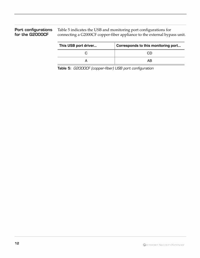
Port configurations for the G2000CF
Table 5 indicates the USB and monitoring port configurations for connecting a G2000CF copper-fiber appliance to the external bypass unit.
This USB port driver... Corresponds to this monitoring port...
C CD
A AB
Table 5: G2000CF (copper-fiber) USB port configuration
12
High Availability Port Connectivity
High Availability Port Connectivity
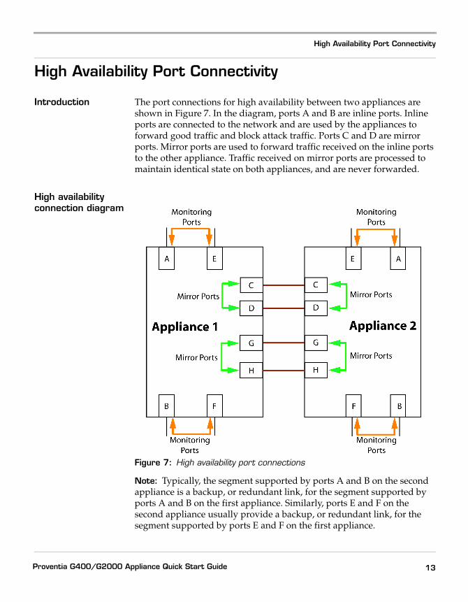
Introduction The port connections for high availability between two appliances are shown in Figure 7. In the diagram, ports A and B are inline ports. Inline ports are connected to the network and are used by the appliances to forward good traffic and block attack traffic. Ports C and D are mirror ports. Mirror ports are used to forward traffic received on the inline ports to the other appliance. Traffic received on mirror ports are processed to maintain identical state on both appliances, and are never forwarded.
High availability connection diagram
Figure 7: High availability port connections
Note: Typically, the segment supported by ports A and B on the second appliance is a backup, or redundant link, for the segment supported by ports A and B on the first appliance. Similarly, ports E and F on the second appliance usually provide a backup, or redundant link, for the segment supported by ports E and F on the first appliance.
13Proventia G400/G2000 Appliance Quick Start Guide
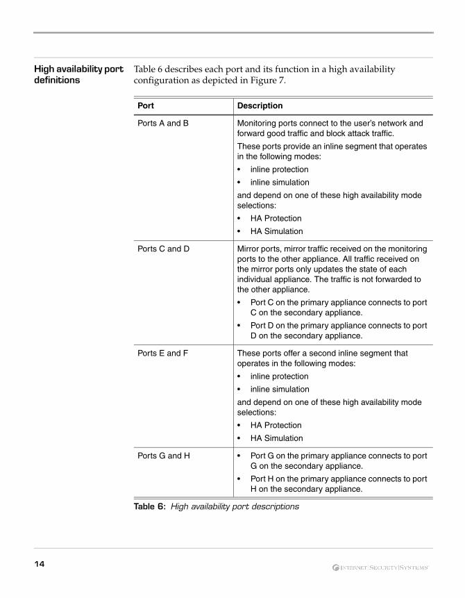
High availability port definitions
Table 6 describes each port and its function in a high availability configuration as depicted in Figure 7.
Port Description
Ports A and B Monitoring ports connect to the user’s network and forward good traffic and block attack traffic.
These ports provide an inline segment that operates in the following modes:
• inline protection
• inline simulation
and depend on one of these high availability mode selections:
• HA Protection
• HA Simulation
Ports C and D Mirror ports, mirror traffic received on the monitoring ports to the other appliance. All traffic received on the mirror ports only updates the state of each individual appliance. The traffic is not forwarded to the other appliance.
• Port C on the primary appliance connects to port C on the secondary appliance.
• Port D on the primary appliance connects to port D on the secondary appliance.
Ports E and F These ports offer a second inline segment that operates in the following modes:
• inline protection
• inline simulation
and depend on one of these high availability mode selections:
• HA Protection
• HA Simulation
Ports G and H • Port G on the primary appliance connects to port G on the secondary appliance.
• Port H on the primary appliance connects to port H on the secondary appliance.
Table 6: High availability port descriptions
14
High Availability Port Connectivity
Cabling requirements for “fail-open” segments
The Proventia G segments are configured to “fail closed” when operating in one of the HA modes. If there is a loss of power or other disruption to the appliance's operation, all traffic is routed through the alternate segment provided by the second appliance. This is the recommended behavior for the appliance.
Note: You can change this configuration by setting the Fail Mode option to Open on the Card Management tab of the Local Tuning Parameters page in Proventia Manager.
In order for the segment to successfully “fail open,” you must use the correct network cables for the inline port pairs. In the event of a loss of power or other disruption, the internal connection between ports A and B (or ports E and F for the second segment) acts as a “crossover” cable. Depending on the type of network equipment attached to the two ports, it may be necessary to connect one of the ports with a crossover cable instead of a straight-through cable.
Example:
If two devices attached to the ports are ordinarily connected with a straight cable, you must use a straight cable attached to one port and a crossover cable attached to the other port. The crossover cable, combined with the crossover provided by the internal fail-open circuitry in the two ports, effectively provides a straight-through connection between the two devices.
If you use the fail-closed setting, it does not matter which type of cable you use because in ordinary operation, the appliance automatically detects and appropriately handles either type of cable. Similarly, it does not matter which type of cables you use to connect the “mirror ports” (ports C, D, G and H); the appliance automatically detects and appropriately handles either cable type.
Note: As delivered, the appliance is in normal mode and all ports on the appliance are set to “fail open.”
Testing connectivity To test connectivity, connect cables to the two ports in each segment before you turn on the appliance or configure it for High Availability mode. Traffic should successfully flow through the cables, from the device attached to port A to the device attached to port B.
15Proventia G400/G2000 Appliance Quick Start Guide
Connecting the Cables and Starting the Appliance
Introduction This topic provides instructions for connecting cables and starting the appliance for the first time.
Important: ISS recommends that the SiteProtector Agent Manager or any remote access computer(s) that communicate with the appliance from the management port are all on the same logical side of the network. If network traffic is unable to traverse the appliance’s network interface card (NIC) and the SiteProtector and remote access computer(s) are not on the same logical side as the management port, they will not be able to communicate with the appliance.
Power connectors The G400 and G2000 appliances have dual standard AC power connectors.
Connecting the power cord
To connect the power cord(s):
1. Press the strain relief into the platform hole until it snaps into place.
2. Insert the power cord into the loop.
Note: Leave some slack in the power cord between the strain relief and the power supply.
3. Pull the tab to secure the power cord in the loop.
4. Plug one end the power cord into the back of the appliance as shown in Figure 2 for the G400 or Figure 4 for the G2000.
5. Plug the other end of the power cord(s) into a standard AC power supply.
Connecting the network cables
To connect the network cables:
1. Connect the management interface on the back panel to the network you will use to manage it.
2. Connect the network cables to correspond with the operation mode (inline or passive) you plan to use for the appliance.
Note: For the G400 and G2000 models, the Kill response is sent through the monitoring ports.
16
Connecting the Cables and Starting the Appliance
Note: There is no need to connect another interface. Ports A through H can be used to monitor different network segments in passive mode.
Reference: If you configure the appliance to operate in inline protection or inline simulation modes, see “Standard Inline Deployment Scenarios” on page 18.
First-time setup with Proventia Setup utility
To perform the configuration setup for the first time on the Proventia G400 or G2000 appliance, you can either connect directly to the appliance or establish a connection to the appliance using a compatible terminal emulator, such as Hyperterminal. Use the terminal emulator to access the Proventia G Setup utility.
Reference: Refer to your Microsoft documentation for instructions on using Hyperterminal.
Connecting the appliance to a computer or laptop
To connect the appliance to a computer or laptop:
1. Plug one end of the serial cable into the serial port on the back of the appliance (Figure 2 or Figure 4, depending on appliance model).
2. Plug the other end of the serial cable into the serial port on your computer or laptop.
3. Use a terminal emulation program, such as Hyperterminal, to create a connection to the appliance.
Setting up terminal emulation
To set up the terminal emulation:
1. In the Hyperterminal application, go to File Properties Settings.
2. Select Emulation = Auto Detect.
3. Click OK.
17Proventia G400/G2000 Appliance Quick Start Guide
Standard Inline Deployment Scenarios
Introduction The Proventia G400C and G2000C appliances have built-in copper bypass hardware, which ensures that traffic continues to pass if the appliance fails or loses power. The G400F and G2000F do not have built-in bypass hardware. You can purchase an optional fiber bypass unit and kit that provides bypass functionality. Contact Internet Security Systems for availability. See “The External Bypass Unit” on page 8.
Note: The G400CF and G2000CF models require the external bypass unit for the fiber ports only.
Caution: You should install the correct network cabling and verify that traffic flows before you turn on the appliance.
Cabling guidelines for standard deployments
Place a CAT5 crossover cable between a Proventia G appliance and a server or a workstation. ISS recommends using a CAT5 crossover cable between a Proventia G appliance and a router. A straight cable is sufficient between a Proventia G appliance and a switch or hub.
Note: Where a crossover is needed, you may use your own CAT5 crossover cable or the provided one-foot cable and crossover coupler that comes with the appliance. When the appliance is not running, its monitoring interfaces function as a crossover. The following scenarios work independently of the monitoring port (A or B) you use.
Important: Cabling guidelines differ for high availability. See “Cabling requirements for “fail-open” segments” on page 15.
Switch/Hub1 to Switch/Hub2
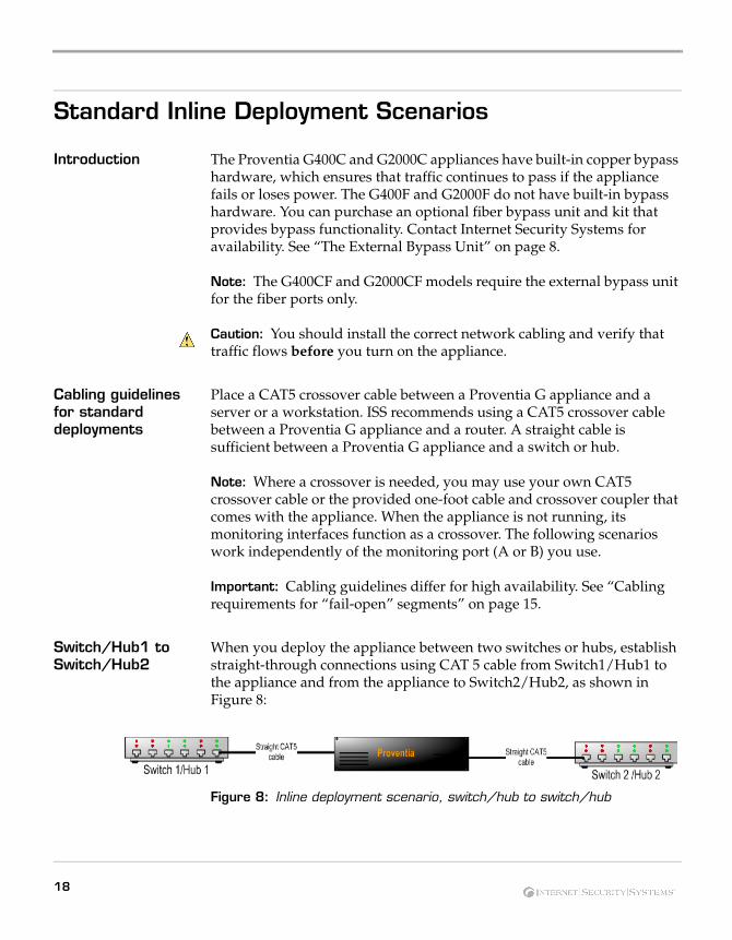
When you deploy the appliance between two switches or hubs, establish straight-through connections using CAT 5 cable from Switch1/Hub1 to the appliance and from the appliance to Switch2/Hub2, as shown in Figure 8:
Figure 8: Inline deployment scenario, switch/hub to switch/hub
18
Standard Inline Deployment Scenarios
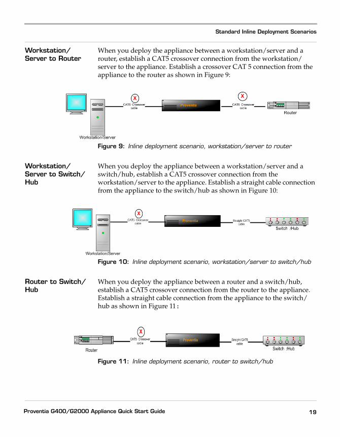
Workstation/Server to Router
When you deploy the appliance between a workstation/server and a router, establish a CAT5 crossover connection from the workstation/server to the appliance. Establish a crossover CAT 5 connection from the appliance to the router as shown in Figure 9:
Figure 9: Inline deployment scenario, workstation/server to router
Workstation/Server to Switch/Hub
When you deploy the appliance between a workstation/server and a switch/hub, establish a CAT5 crossover connection from the workstation/server to the appliance. Establish a straight cable connection from the appliance to the switch/hub as shown in Figure 10:
Figure 10: Inline deployment scenario, workstation/server to switch/hub
Router to Switch/Hub
When you deploy the appliance between a router and a switch/hub, establish a CAT5 crossover connection from the router to the appliance. Establish a straight cable connection from the appliance to the switch/hub as shown in Figure 11:
Figure 11: Inline deployment scenario, router to switch/hub
19Proventia G400/G2000 Appliance Quick Start Guide
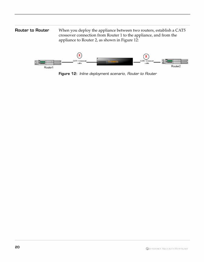
Router to Router When you deploy the appliance between two routers, establish a CAT5 crossover connection from Router 1 to the appliance, and from the appliance to Router 2, as shown in Figure 12:
Figure 12: Inline deployment scenario, Router to Router
20
High Availability Deployment
High Availability Deployment
Introduction The Proventia G400/G2000 high availability (HA) feature supports two types of network configurations. The two supported network configurations are:
● Primary / Secondary
● Clustering
HA network configuration
The Proventia G appliances are connected by mirror links, consisting of multiple connections over multiple ports. These mirror links pass all traffic that the primary G appliance receives on its inline ports to the secondary G appliance. This ensures that the protocol analysis modules on both appliances process all of the traffic over the network, so both appliances maintain an identical state. This also allows the appliances to process asymmetrically routed traffic, so the network is fully protected. There is no gap in protection during failover. Table 7 describes the two ways in which high availability networks are typically configured:
HA network configuration
Description
Primary / Secondary configuration
With this configuration, the traffic flows only on one of the redundant network segments and the primary devices on the network handle all of the traffic until one of the devices fails, at which point the traffic fails over to the secondary redundant network segment and the secondary devices take over.
Clustering configuration
With this configuration, the traffic is load balanced and both sets of devices are active and see traffic all of the time.
Table 7: Types of HA network configurations
21Proventia G400/G2000 Appliance Quick Start Guide
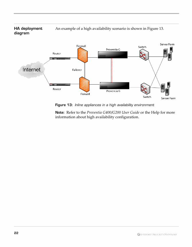
HA deployment diagram
An example of a high availability scenario is shown in Figure 13.
Figure 13: Inline appliances in a high availability environment
Note: Refer to the Proventia G400/G200 User Guide or the Help for more information about high availability configuration.
22
Chapter 2
Configuring the Appliance
Overview
Introduction This chapter describes how to configure Proventia G400 and G2000 models. Initial network configuration is performed in the Proventia Setup utility. You can configure your appliance management settings in either SiteProtector or the local Web-based interface, Proventia Manager.
In this chapter This chapter contains the following topics:
Topic Page
Before You Begin 24
Logging On and Configuring the G400 or G2000 Appliance 26
Accessing Proventia Manager for G400 and G2000 30
Connecting to SiteProtector 33
Configuring SiteProtector Management 36
Configuring Inline High Availability 38
23Proventia G400/G2000 Appliance Quick Start Guide
Before You Begin
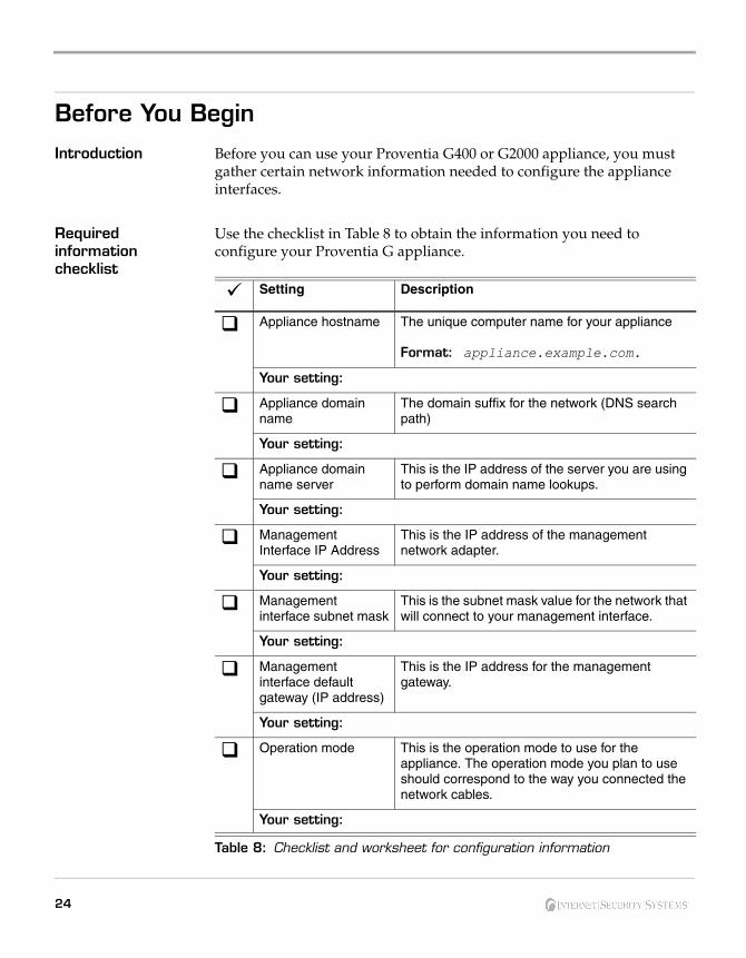
Introduction Before you can use your Proventia G400 or G2000 appliance, you must gather certain network information needed to configure the appliance interfaces.
Required information checklist
Use the checklist in Table 8 to obtain the information you need to configure your Proventia G appliance.
Setting Description
Appliance hostname The unique computer name for your appliance
Format: appliance.example.com.
Your setting:
Appliance domain name
The domain suffix for the network (DNS search path)
Your setting:
Appliance domain name server
This is the IP address of the server you are using to perform domain name lookups.
Your setting:
Management Interface IP Address
This is the IP address of the management network adapter.
Your setting:
Management interface subnet mask
This is the subnet mask value for the network that will connect to your management interface.
Your setting:
Management interface default gateway (IP address)
This is the IP address for the management gateway.
Your setting:
Operation mode This is the operation mode to use for the appliance. The operation mode you plan to use should correspond to the way you connected the network cables.
Your setting:
Table 8: Checklist and worksheet for configuration information
24
Before You Begin
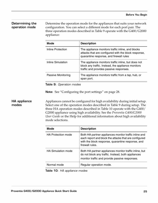
Determining the operation mode
Determine the operation mode for the appliances that suits your network configuration. You can select a different mode for each port pair. The three operation modes described in Table 9 operate with the G400/G2000 appliance:
Note: See “Configuring the port settings” on page 28.
HA appliance modes
Appliances cannot be configured for high availability during initial setup. Select one of the operation modes described in Table 9 during setup. The three HA operation modes described in Table 10 operate with the G400/G2000 appliance using high availability. See the Proventia G400/G2000 User Guide or the Help for additional information about high availability mode selections.
Mode Description
Inline Protection The appliance monitors traffic inline, and blocks attacks that are configured with the block response, quarantine response, and firewall rules
Inline Simulation The appliance monitors traffic inline, but does not block any traffic. Instead, the appliance monitors traffic and provides passive responses.
Passive Monitoring The appliance monitors traffic from a tap, hub, or span port.
Table 9: Operation modes
Mode Description
HA Protection mode Both HA partner appliances monitor traffic inline and each report and block the attacks that are configured with the block response, quarantine response, and firewall rules.
HA Simulation mode Both HA partner appliances monitor traffic inline, but do not block any traffic. Instead, both appliances monitor traffic and provide passive responses.
Normal mode Regular operation mode.
Table 10: HA appliance modes
25Proventia G400/G2000 Appliance Quick Start Guide
Logging On and Configuring the G400 or G2000 Appliance
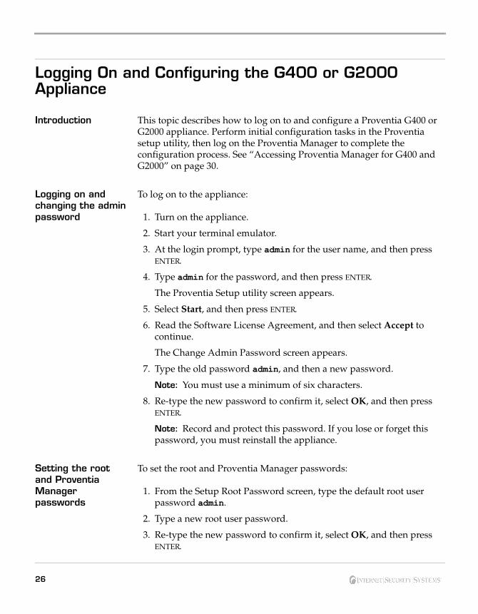
Introduction This topic describes how to log on to and configure a Proventia G400 or G2000 appliance. Perform initial configuration tasks in the Proventia setup utility, then log on the Proventia Manager to complete the configuration process. See “Accessing Proventia Manager for G400 and G2000” on page 30.
Logging on and changing the admin password
To log on to the appliance:
1. Turn on the appliance.
2. Start your terminal emulator.
3. At the login prompt, type admin for the user name, and then press ENTER.
4. Type admin for the password, and then press ENTER.
The Proventia Setup utility screen appears.
5. Select Start, and then press ENTER.
6. Read the Software License Agreement, and then select Accept to continue.
The Change Admin Password screen appears.
7. Type the old password admin, and then a new password.
Note: You must use a minimum of six characters.
8. Re-type the new password to confirm it, select OK, and then press ENTER.
Note: Record and protect this password. If you lose or forget this password, you must reinstall the appliance.
Setting the root and Proventia Manager passwords
To set the root and Proventia Manager passwords:
1. From the Setup Root Password screen, type the default root user password admin.
2. Type a new root user password.
3. Re-type the new password to confirm it, select OK, and then press ENTER.
26
Logging On and Configuring the G400 or G2000 Appliance
Note: You will need this password for command line access.
The Proventia Manager password screen appears.
4. Type the Proventia Manager default password, admin.
5. Type a new password
6. Type the new password again to confirm it.
Note: You will need this password to access the Proventia Manager interface.
7. Select OK, and then press ENTER.
The Network Configuration screen appears.
Configuring the network interface and host
To configure the network interface and host:
1. On the Network Configuration screen, type the IP Address, Subnet Mask, and Gateway of the appliance’s management interface.
2. Select OK, and then press ENTER.
The Host Configuration screen appears.
3. Type the Hostname, Domain Name, and Name Servers (optional, primary and secondary) for the appliance.
4. Select OK, and then press ENTER.
Note: The appliance uses domain names and DNS information to send email and SNMP responses. If you do not provide this information now, then you must specify the IP address of the appliance’s mail server when you define the email response on the management console. The appliance must have network access to the mail server.
Configuring the date and time
To configure the date and time at which events occur:
1. Select the continent or ocean where the appliance is located, and then press ENTER.
2. Select the country where the appliance is located, and then press ENTER.
3. Select the timezone region where the appliance is located, and then press ENTER.
27Proventia G400/G2000 Appliance Quick Start Guide
Note: This screen does not appear if the country you selected contains only one time zone.
4. Select OK, and then press ENTER.
A Timezone Confirmation screen appears.
5. Review your selections, select OK, and then press ENTER.
6. The Date/Time configuration screen appears.
7. Press ENTER to accept the default time, or type a new time.
Note: Use the format [HH:MM:SS] and a 24-hour clock.
8. Press ENTER to accept the default date, or type a new date.
Note: Use the format [mm/dd/yyyy]
The Agent Name Configuration screen appears.
Configuring the agent name
The Agent Name is the asset name that appears for this appliance in your management interface. ISS recommends that you select a name that corresponds to the appliance’s geographic location, business unit, building address, or some other meaningful classification.
To configure the agent name:
1. Press ENTER to accept the default Agent Name, or type a specific name.
2. Select OK, and then press ENTER.
The Port Link Configuration screen appears.
Configuring the port settings
The G400 and G2000 appliances have eight ports labeled A through H. You can configure link speed, duplex mode and operational mode settings appropriate for each port pair on the appliance.
To configure the link speed and mode settings:
1. Select Port A, and then do one of the following:
■ Press the DOWN ARROW to select the port link speed and modes
■ Press ENTER to accept the default settings
2. Press TAB to move from port to port.
3. Select Port B, and then do one of the following:
28
Logging On and Configuring the G400 or G2000 Appliance
■ Press the DOWN ARROW to select the port link speed and modes
■ Press ENTER to accept the default settings
4. Repeat Step 1 and Step 2 to select additional ports.
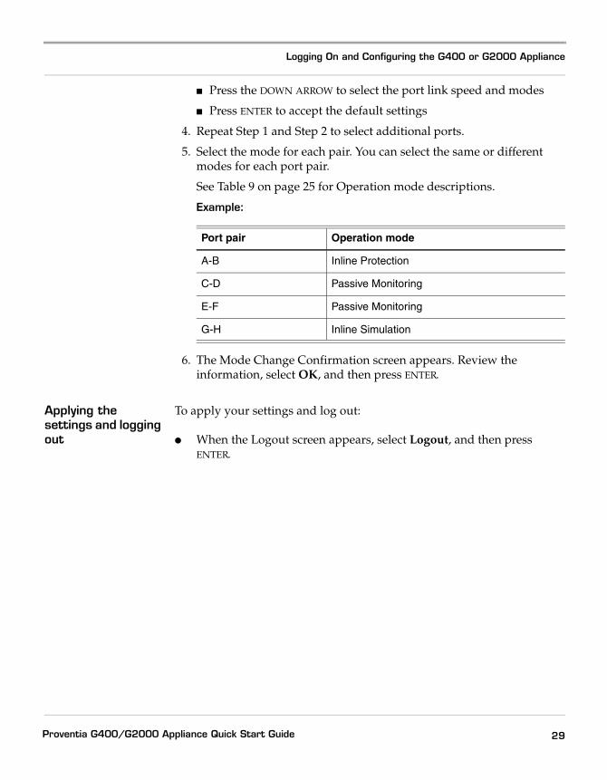
5. Select the mode for each pair. You can select the same or different modes for each port pair.
See Table 9 on page 25 for Operation mode descriptions.
Example:
6. The Mode Change Confirmation screen appears. Review the information, select OK, and then press ENTER.
Applying the settings and logging out
To apply your settings and log out:
● When the Logout screen appears, select Logout, and then press ENTER.
Port pair Operation mode
A-B Inline Protection
C-D Passive Monitoring
E-F Passive Monitoring
G-H Inline Simulation
29Proventia G400/G2000 Appliance Quick Start Guide
Accessing Proventia Manager for G400 and G2000
Introduction This topic describes how to log on to and use the Proventia Manager local management interface for your Proventia G appliance.
Using Proventia Manager
Use Proventia Manager to perform the following tasks:
● monitor the status of the appliance
● configure and manage settings
● view quarantine table and apply changes
● review and manage appliance activities
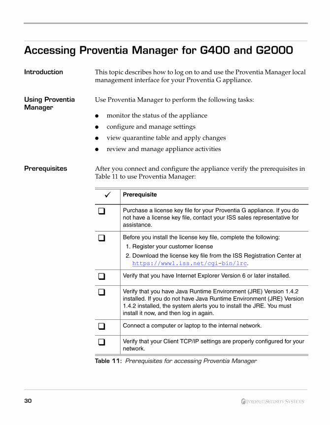
Prerequisites After you connect and configure the appliance verify the prerequisites in Table 11 to use Proventia Manager:
Prerequisite
Purchase a license key file for your Proventia G appliance. If you do not have a license key file, contact your ISS sales representative for assistance.
Before you install the license key file, complete the following:
1. Register your customer license
2. Download the license key file from the ISS Registration Center at https://www1.iss.net/cgi-bin/lrc.
Verify that you have Internet Explorer Version 6 or later installed.
Verify that you have Java Runtime Environment (JRE) Version 1.4.2 installed. If you do not have Java Runtime Environment (JRE) Version 1.4.2 installed, the system alerts you to install the JRE. You must install it now, and then log in again.
Connect a computer or laptop to the internal network.
Verify that your Client TCP/IP settings are properly configured for your network.
Table 11: Prerequisites for accessing Proventia Manager
30

Accessing Proventia Manager for G400 and G2000
Licensing Proventia G appliances require a properly configured license file. If you have not installed the appropriate license file through the management console, you will not be able to manage the appliance.
Licensing for a high availability configuration is identical to licensing for a non-HA appliance. Each individual appliance requests a single license from SiteProtector.
Purchasing a license: To purchase a license for a Proventia G appliance, contact your local sales representative.
Logging on to Proventia Manager
To log on to the Proventia Manager interface:
1. Start Internet Explorer 6.
2. Type https:// followed by the IP address of the appliance’s management interface you configured during initial configuration. See “Required information checklist” on page 24.
3. Log in using the user name “admin” and the Proventia Manager password you configured in the procedure, “Setting the root and Proventia Manager passwords” on page 26.
4. If a message informs you that you do not have Java2 Runtime Environment (JRE) Version 1.4.2 installed, install it, and then return to this procedure.
The Welcome screen appears.
31Proventia G400/G2000 Appliance Quick Start Guide
5. Do one of the following:
■ Select Yes to use the Getting Started procedures.
■ Select No to continue without using the Getting Started procedures.
Note: ISS recommends that you use the Getting Started procedures to help you customize the appliance settings. If this window does not appear, you can also access the Getting Started procedures from the Help.
6. Click Launch Proventia Manager.
32
Connecting to SiteProtector
Connecting to SiteProtector
Introduction This topic explains how to connect the G appliances to the SiteProtector Agent Manager.
Using SiteProtector Management
SiteProtector is the ISS agent manager. SiteProtector can manage a variety of network agents. If you use the SiteProtector with your appliance, you can do the following:
● Report alerts and events to the SiteProtector Agent Manager
● Enable SiteProtector Agent Manager to manage many important functions of your appliance
Important: You must configure SiteProtector management of your appliance on the Management page of Proventia Manager.
Using SiteProtector with HA
High availability configurations are visible to Proventia Manager and are capable of accepting policies and updates, but it is recommended to use SiteProtector to manage the G400/G2000 appliances when using inline high availability configurations. Each pair of Proventia G appliances in a high availability configuration must be put in the same group in SiteProtector so that updates to the sensors can be easily synchronized, including application of XPUs and policies.
Note: It is recommended that both HA partner appliances are configured to use the same policies.
Updating the appliances
The user may choose to apply content updates and firmware updates serially so that one appliance is always operational in order to maintain network connectivity, particularly when both appliances are configured to fail closed.
Important: SiteProtector must be updated to SR 5.6 prior to installing the Proventia G400/G2000 Firmware 1.1.
HA limitations in SiteProtector
In HA mode, using adapter parameters as part of the firewall rules and protection domain definitions is not supported. As the same traffic may flow on different adapters in an HA environment, using adapter parameters may cause the two HA partner appliances to become unsynchronized. For more information, see the Proventia G400/G2000 User Guide or the Help.
33Proventia G400/G2000 Appliance Quick Start Guide
Appliance functions you can manage in SiteProtector
When you register your appliance with SiteProtector, then SiteProtector controls the following management functions of the appliance:
● firewall polices
● notification
● intrusion prevention
● system settings
● updates
When you register the appliance with a SiteProtector group, you can do the following:
● Allow the appliance to inherit appliance group settings
● Manage some or all of settings for a single appliance in the group independently in SiteProtector, so that the appliance maintains those individual settings regardless of group settings
Note: For more information about using SiteProtector agent manager with your appliance, see the SiteProtector documentation.
When to use Proventia Manager
You must manage some settings in Proventia Manager, even when the appliance is registered with SiteProtector. Use Proventia Manager for the following tasks:
● Assign management of device to SiteProtector
● Revoke SiteProtector's management of the appliance, and restore management to Proventia Manager
● View quarantine table and apply changes
Registering an appliance with SiteProtector
When you register your appliance in SiteProtector, you assign the appliance to a group in the Desired SiteProtector Group for agent field. You can configure group settings in SiteProtector, and SiteProtector can apply those settings to some or all appliances in the group.
In the SiteProtector interface, appliances and other protection agents are called “agents,” and you manage the appliance settings on the Agents tab. An appliance can only be assigned to an agent group that includes other G appliances.
Important: Do not assign an appliance to a group that contains other types of appliances.
34
Connecting to SiteProtector
Appliance heartbeat in SiteProtector
A heartbeat is an encrypted, periodic HTTP request that the appliance uses to indicate it is still running and to allow it to receive updates from the Desktop Controller. When you register the appliance with SiteProtector, you specify the time interval between heartbeats to SiteProtector.
When you register the appliance with SiteProtector, you can override SiteProtector settings on the appliance for the first heartbeat. This allows the appliance to maintain its own local settings until you change the settings in SiteProtector.
Note: For instructions on managing the appliance from the management console, see the SiteProtector user documentation. Also see the SiteProtector Help and Proventia Manager Help.
Accessing the SiteProtector Help
To access the SiteProtector Help:
1. On the SiteProtector Console menu bar, select Help SiteProtector Help.
2. Open the Working with Proventia A and Proventia G Appliances and Sensors section.
3. Look up “Working with Proventia Appliance Policies” and “Working with Asset Properties and Responses.”
35Proventia G400/G2000 Appliance Quick Start Guide
Configuring SiteProtector Management
Introduction For G400 and G200 models, you must configure your SiteProtector management settings in Proventia Manager. See “Accessing Proventia Manager for G400 and G2000” on page 30.
Configuring SiteProtector management
To configure SiteProtector management of your appliance:
1. In the Proventia Manager navigation pane, click + to expand the System node.
2. Select Management.
The Management page appears.
3. Select the Register with SiteProtector check box.
4. Do you want local appliance settings to override SiteProtector group settings?
■ If yes, select the Local Settings Override SiteProtector Group Settings box.
■ If no, clear the Local Settings Override SiteProtector Group Settings box.
5. Type a valid SiteProtector group name in the Desired SiteProtector Group for appliance box.
6. In the Heartbeat Interval (secs): field, type the number of seconds that you want the appliance to wait between heartbeats to SiteProtector.
This value must be between 60 and 86,400 seconds.
7. Configure the SiteProtector Agent Manager.
SiteProtector Agent Manager configuration
To configure the SiteProtector Agent Manager:
1. In the navigation pane, click + to expand the System node.
2. Select Management.
The Management page appears.
3. In the Agent Manager Configuration area, click Add.
The Add Agent Manager Configuration window appears.
36
Configuring SiteProtector Management
4. Select the Authentication Level.
5. Type a meaningful name that corresponds to the SiteProtector agent manager in the Name box.
6. Type the IP address of the SiteProtector agent manager in the Agent Manager Address box.
7. Type the port number on which alerts are sent to SiteProtector in the Agent Manager Port box.
■ The default port number is 3995. If you change the default port number, you must also configure the port number locally on the SiteProtector agent manager.
8. Type the account name for the agent manager in the Account Name box.
9. Configure the password.
Configuring the password
To configure the password:
1. In the Agent Manager configuration screen, click Set Password.
The Set Password window appears.
2. Type a password in the Password box.
3. Type the password again in the Confirm Password box, and then click OK.
4. Is a proxy server installed in the network between the appliance and SiteProtector?
■ If yes, select the Use Proxy Settings check box, and then go to Step 5.
■ If no, clear the Use Proxy Settings check box, and then go to Step 7.
5. Type the IP address of the proxy server in the Proxy Server Address box.
6. Type the port number of the proxy server in the Proxy Server Port box.
7. Click OK.
8. Click Save Changes.
37Proventia G400/G2000 Appliance Quick Start Guide
Configuring Inline High Availability
Introduction Important: YOU MUST INSTALL PROVENTIA G400/G2000 FIRMWARE UPDATE 1.1 TO ENABLE THE HIGH AVAILABILITY FEATURE.
The Proventia G400 and G2000 Intrusion Prevention Appliances with inline high availability (HA) enables appliances to work in an existing high availability network environment. Two appliances are connected and pass synchronized information between them. This ensures that both appliances see all of the traffic over the network and thus maintain state. This allows the appliances to see asymmetrically routed or load balanced traffic, and therefore fully protect the network. Both appliances process packets inline and block attack traffic that arrives on their monitoring ports, not on their interconnection ports. Both appliances can report events, however, only one of the appliances reports the events to the management console. Therefore, duplicate events will not occur.
Prerequisites for high availability
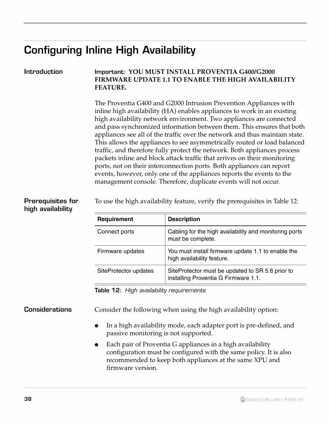
To use the high availability feature, verify the prerequisites in Table 12:
Considerations Consider the following when using the high availability option:
● In a high availability mode, each adapter port is pre-defined, and passive monitoring is not supported.
● Each pair of Proventia G appliances in a high availability configuration must be configured with the same policy. It is also recommended to keep both appliances at the same XPU and firmware version.
Requirement Description
Connect ports Cabling for the high availability and monitoring ports must be complete.
Firmware updates You must install firmware update 1.1 to enable the high availability feature.
SiteProtector updates SiteProtector must be updated to SR 5.6 prior to installing Proventia G Firmware 1.1.
Table 12: High availability requirements
38
Configuring Inline High Availability
● A high availability configuration uses two inline ports and two mirror ports. This allows a single eight port appliance to support two independent high availability network segments. Both of these inline segments must operate in the same mode, either Protection or Simulation.
● Appliances cannot be configured for high availability mode during the initial setup in the Proventia Setup Utility. Select one of the standard appliance modes during the initial setup, and then refer to High Availability Configuration topics in the Proventia G400/G2000 User Guide or the Help for detailed procedures for enabling HA modes.
Note: For detailed high availability configuration procedures and management information, refer to the Proventia G400/G2000 User Guide and the Help.
39Proventia G400/G2000 Appliance Quick Start Guide

40
Chapter 3
Reinstalling the Appliance
Overview Introduction This chapter describes the process and procedures for reinstalling the
Proventia G400 and G2000 Intrusion Prevention Appliances. You must reinstall the appliance software to restore the appliance to its original configuration and to remove any customized settings.
What you need To reinstall a G appliance, you need the following:
● a computer to use as your configuration interface
● a Proventia G Appliance Recovery CD (model-specific)
In this chapter This chapter contains the following topics:
Topic Page
Reinstallation Requirements 42
Reinstalling the Appliance 43
Getting Technical Support 44
41Proventia G400/G2000 Appliance Quick Start Guide
Reinstallation Requirements
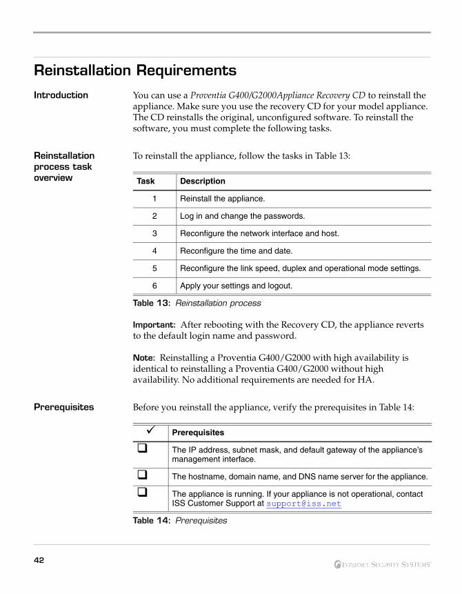
Introduction You can use a Proventia G400/G2000Appliance Recovery CD to reinstall the appliance. Make sure you use the recovery CD for your model appliance. The CD reinstalls the original, unconfigured software. To reinstall the software, you must complete the following tasks.
Reinstallation process task overview
To reinstall the appliance, follow the tasks in Table 13:
Important: After rebooting with the Recovery CD, the appliance reverts to the default login name and password.
Note: Reinstalling a Proventia G400/G2000 with high availability is identical to reinstalling a Proventia G400/G2000 without high availability. No additional requirements are needed for HA.
Prerequisites Before you reinstall the appliance, verify the prerequisites in Table 14:
Task Description
1 Reinstall the appliance.
2 Log in and change the passwords.
3 Reconfigure the network interface and host.
4 Reconfigure the time and date.
5 Reconfigure the link speed, duplex and operational mode settings.
6 Apply your settings and logout.
Table 13: Reinstallation process
Prerequisites
The IP address, subnet mask, and default gateway of the appliance’s management interface.
The hostname, domain name, and DNS name server for the appliance.
The appliance is running. If your appliance is not operational, contact ISS Customer Support at [email protected]
Table 14: Prerequisites
42
Reinstalling the Appliance
Reinstalling the Appliance
Introduction Use the following procedure to reinstall the Proventia G400 or G2000 Intrusion Prevention appliance software.
Reinstalling the appliance
To reinstall the appliance:
1. If there is a bezel cover on the front of the appliance, remove it.
2. Place the Proventia G400 or G2000 Appliance Recovery CD in the CD-ROM drive.
3. Connect a computer or monitor and keyboard to the appliance.
4. Reference: For more information, see “Connecting the appliance to a computer or laptop” on page 16.
5. Restart the appliance. You can manually turn the power off and on if the appliance is not responding.
6. Type reinstall, and then press ENTER.
7. The appliance reloads the operating system, displays status messages, ejects the CD, and then reboots.
8. Log in and change the password. See “Logging on and changing the admin password” on page 26.
9. Reconfigure the appliance. See “Logging On and Configuring the G400 or G2000 Appliance” on page 26.
10. Press ENTER.
Applying settings To apply settings:
1. After the appliance applies your configuration settings, and then displays a message the configuration is complete, press ENTER.
The appliance displays a logout confirmation message.
2. Press ENTER.
The login screen appears.
Note: You must use the Web-based Proventia Manager interface to complete the remaining appliance management configuration. You can change your appliance settings and passwords in Proventia Manager on the System Access Control page.
43Proventia G400/G2000 Appliance Quick Start Guide
Getting Technical Support
Introduction ISS provides technical support through its Web site and by email or telephone.
The ISS Web site The Internet Security Systems (ISS) Resource Center Web site (http://www.iss.net/support/) provides direct access to frequently asked questions (FAQs), white papers, online user documentation, current versions listings, detailed product literature, and the Technical Support Knowledgebase (http://www.iss.net/support/knowledgebase/).
Support levels ISS offers three levels of support:
● Standard
● Select
● Premium
Each level provides you with 24-7 telephone and electronic support. Select and Premium services provide more features and benefits than the Standard service. Contact Client Services at [email protected] if you do not know the level of support your organization has selected.
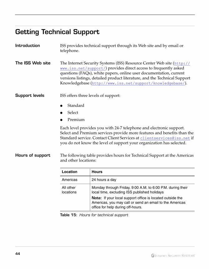
Hours of support The following table provides hours for Technical Support at the Americas and other locations:
Location Hours
Americas 24 hours a day
All other locations
Monday through Friday, 9:00 A.M. to 6:00 P.M. during their local time, excluding ISS published holidays
Note: If your local support office is located outside the Americas, you may call or send an email to the Americas office for help during off-hours.
Table 15: Hours for technical support
44
Getting Technical Support
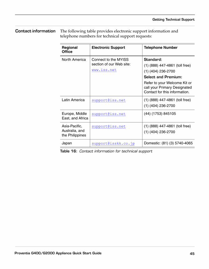
Contact information The following table provides electronic support information and telephone numbers for technical support requests:
Regional Office
Electronic Support Telephone Number
North America Connect to the MYISS section of our Web site:
www.iss.net
Standard:(1) (888) 447-4861 (toll free)
(1) (404) 236-2700
Select and Premium:Refer to your Welcome Kit or call your Primary Designated Contact for this information.
Latin America [email protected] (1) (888) 447-4861 (toll free)
(1) (404) 236-2700
Europe, Middle East, and Africa
[email protected] (44) (1753) 845105
Asia-Pacific, Australia, and the Philippines
[email protected] (1) (888) 447-4861 (toll free)
(1) (404) 236-2700
Japan [email protected] Domestic: (81) (3) 5740-4065
Table 16: Contact information for technical support
45Proventia G400/G2000 Appliance Quick Start Guide

46
Index
aabout Intrusion Prevention Appliances viagent name 28alerts and events 33appliance
accessing proventia manager 30capabilities viconfiguration checklist 24functions 34logging on 26logging out 29registering with SiteProtector 34updates 33
bblock attack traffic 38
ccabling guidelines 17configuring
agent name 28date and time 27high availability (HA) 38link speed and duplex mode settings 28network interface 27password 37port settings 28SiteProtector management 36
connectionshigh availability 12
Proventia G400/G2000 Appliance Quick Start Guide
ddiagram
external bypass unit 8G2000CF back panel 6G2000F back panel 5G400 back panel 3G400/G2000 front panel 2G400CF back panel 4
domain names 27
eemail responses 27external bypass unit 7
ffault LED 2
ggroup settings 34
hheartbeats 35high availability
connections 12considerations 38network 21prerequisites 38
47
Index
iinline protection 25inline simulation 25Internet Security Systems
technical support 44Web site 44
llicense file
HA 31installing 26non-HA 31purchasing 26
logging on and changing the admin password 26
mmanagement console 31
user documentation 35managing the appliance 35mid-mount kit 1
nnetwork cables 15notification 34
oonline Help
for SiteProtector 35operation modes
HA 25non-HA 25
48
ppassive monitoring 25passwords 26periodic HTTP 35power connectors 15Proventia Manager viiProventia setup utility vi, 26
rrack mounting procedures 1recovery CD 42reinstalling 41
process 42required procedures 42
related publications viii
sserial cable 16setting the root and Proventia Manager
passwords 26SiteProtector
HA limitations 33Help 35using with HA 33
SiteProtector console 33slide rail kit 1SNMP responses 27
ttechnical support, Internet Security
Systems 44terminal emulator 16To 27tool-less slide rail kit 1
Index
wWeb site, Internet Security Systems 44
Proventia G400/G2000 Appliance Quick Start Guide
49
Index
50