Embed Size (px)
Citation preview
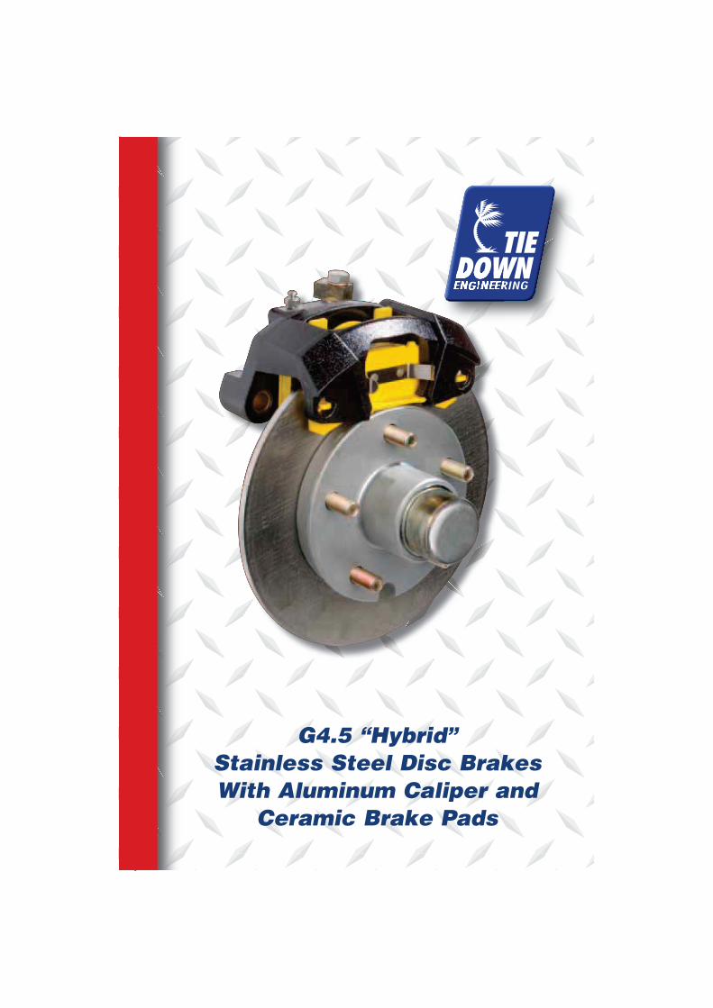
G4.5 “Hybrid”
Stainless Steel Disc Brakes
With Aluminum Caliper and
Ceramic Brake Pads
Read your trailer manufacturer’s operating manual and follow the towing vehicle’s
guidelines for towing capability, hitch requirements and other towing information related
to your trailer GVWR (Gross Vehicle Weight Rating)
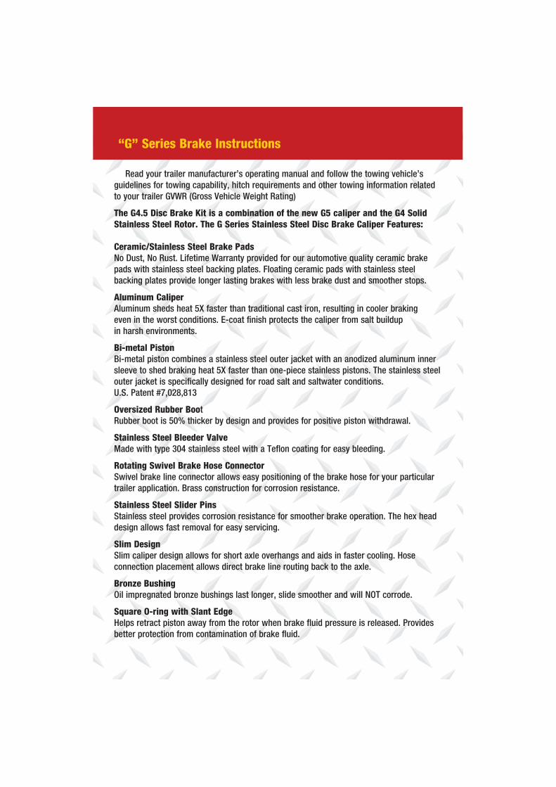
The G4.5 Disc Brake Kit is a combination of the new G5 caliper and the G4 Solid
Stainless Steel Rotor. The G Series Stainless Steel Disc Brake Caliper Features:
Ceramic/Stainless Steel Brake Pads
No Dust, No Rust. Lifetime Warranty provided for our automotive quality ceramic brake
pads with stainless steel backing plates. Floating ceramic pads with stainless steel
backing plates provide longer lasting brakes with less brake dust and smoother stops.
Aluminum Caliper
Aluminum sheds heat 5X faster than traditional cast iron, resulting in cooler braking
even in the worst conditions. E-coat finish protects the caliper from salt buildup
in harsh environments.
Bi-metal Piston
Bi-metal piston combines a stainless steel outer jacket with an anodized aluminum inner
sleeve to shed braking heat 5X faster than one-piece stainless pistons. The stainless steel
outer jacket is specifically designed for road salt and saltwater conditions.
U.S. Patent #7,028,813
Oversized Rubber Boot
Rubber boot is 50% thicker by design and provides for positive piston withdrawal.
Stainless Steel Bleeder Valve
Made with type 304 stainless steel with a Teflon coating for easy bleeding.
Rotating Swivel Brake Hose Connector
Swivel brake line connector allows easy positioning of the brake hose for your particular
trailer application. Brass construction for corrosion resistance.
Stainless Steel Slider Pins
Stainless steel provides corrosion resistance for smoother brake operation. The hex head
design allows fast removal for easy servicing.
Slim Design
Slim caliper design allows for short axle overhangs and aids in faster cooling. Hose
connection placement allows direct brake line routing back to the axle.
Bronze Bushing
Oil impregnated bronze bushings last longer, slide smoother and will NOT corrode.
Square O-ring with Slant Edge
Helps retract piston away from the rotor when brake fluid pressure is released. Provides
better protection from contamination of brake fluid.
“G” Series Brake Instructions
2
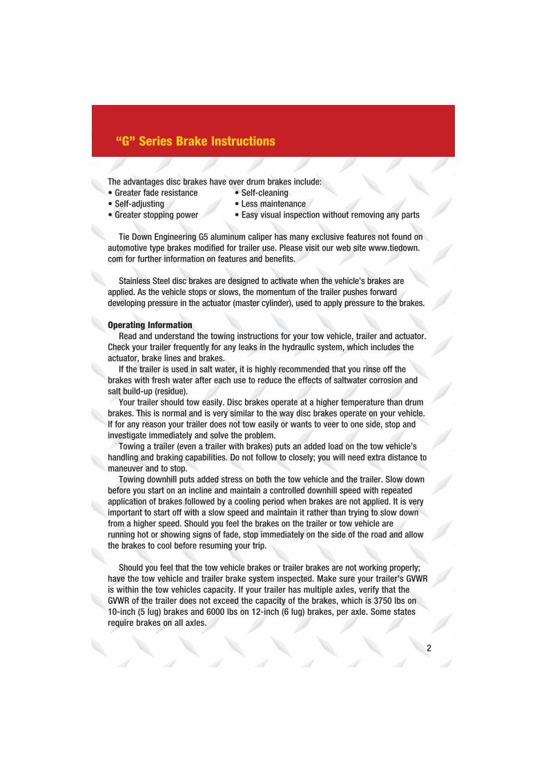
The advantages disc brakes have over drum brakes include:
Tie Down Engineering G5 aluminum caliper has many exclusive features not found on
automotive type brakes modified for trailer use. Please visit our web site www.tiedown.
com for further information on features and benefits.
Stainless Steel disc brakes are designed to activate when the vehicle’s brakes are
applied. As the vehicle stops or slows, the momentum of the trailer pushes forward
developing pressure in the actuator (master cylinder), used to apply pressure to the brakes.
Operating Information
Read and understand the towing instructions for your tow vehicle, trailer and actuator.
Check your trailer frequently for any leaks in the hydraulic system, which includes the
actuator, brake lines and brakes.
If the trailer is used in salt water, it is highly recommended that you rinse off the
brakes with fresh water after each use to reduce the effects of saltwater corrosion and
salt build-up (residue).
Your trailer should tow easily. Disc brakes operate at a higher temperature than drum
brakes. This is normal and is very similar to the way disc brakes operate on your vehicle.
If for any reason your trailer does not tow easily or wants to veer to one side, stop and
investigate immediately and solve the problem.
Towing a trailer (even a trailer with brakes) puts an added load on the tow vehicle’s
handling and braking capabilities. Do not follow to closely; you will need extra distance to
maneuver and to stop.
Towing downhill puts added stress on both the tow vehicle and the trailer. Slow down
before you start on an incline and maintain a controlled downhill speed with repeated
application of brakes followed by a cooling period when brakes are not applied. It is very
important to start off with a slow speed and maintain it rather than trying to slow down
from a higher speed. Should you feel the brakes on the trailer or tow vehicle are
running hot or showing signs of fade, stop immediately on the side of the road and allow
the brakes to cool before resuming your trip.
Should you feel that the tow vehicle brakes or trailer brakes are not working properly;
have the tow vehicle and trailer brake system inspected. Make sure your trailer’s GVWR
is within the tow vehicles capacity. If your trailer has multiple axles, verify that the
GVWR of the trailer does not exceed the capacity of the brakes, which is 3750 lbs on
10-inch (5 lug) brakes and 6000 lbs on 12-inch (6 lug) brakes, per axle. Some states
require brakes on all axles.
“G” Series Brake Instructions
3
Check with your state laws and the state laws of where you will be using your trailer
prior to towing.
After long trips or downhill towing, your brakes could become very hot and it is a good
idea to let them cool down before submerging in cold water. The change in temperature of
very hot brakes submerged in water creates additional stress on the parts and could cause
damage to your brakes.
Pads must be replaced when the friction material is 3/32” or less. Original Tie Down
Engineering brake pads for the Stainless Steel disc brakes have a ceramic pad material
and a stainless steel backing plate that aids in corrosion resistance.
Disc brakes require the use of flexible brake lines attached to the caliper. The calipers
“float” and should not be used with metal brake lines that will restrict movement and cause
overheating or brake failure. If you are replacing existing brakes and using the existing metal
brake lines, either replace metal brake lines with a Tie Down Engineering brake line kit or
add flexible extensions to the metal lines to connect to the disc brake calipers.
Disc brakes require the use of an actuator designed for disc brakes. If you are
replacing drum brakes, you must also change the actuator to a disc brake model. Using a
drum brake actuator with disc brakes will cause overheating, loss of braking power and
possible brake failure.
Use DOT 3 brake fluid only. DOT 3 can be labeled as “synthetic”.
DO NOT USE SILICONE BASED BRAKE FLUID.
When backing a trailer with disc brakes, you must have a lockout device on the actuator
or preferably an electrically operated solenoid to stop brake pressure to the disc brakes.
The solenoid is mounted at the rear of the actuator, between the master cylinder and brake
line. The solenoid has a wire that is connected to your back up lights. When the tow vehicle
transmission is put in reverse, the reverse light voltage activates the solenoid. This will either
stop or redirect the brake fluid to keep the brakes from operating while in reverse.
G Series Brake Instructions
4
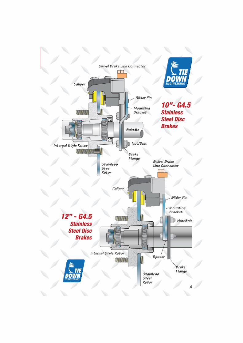
Slider Pin
Swivel Brake Line Connector
Swivel Brake Line Connector
Caliper
Caliper
StainlessSteelRotor
StainlessSteelRotor
Spindle
Nut/Bolt
BrakeFlange
MountingBracket
Slider Pin
MountingBracket
Nut/Bolt
BrakeFlange
Spacer
Intergal Style Rotor
Intergal Style Rotor
10”- G4.5
Stainless
Steel Disc
Brakes
12” - G4.5
Stainless
Steel Disc
Brakes
5
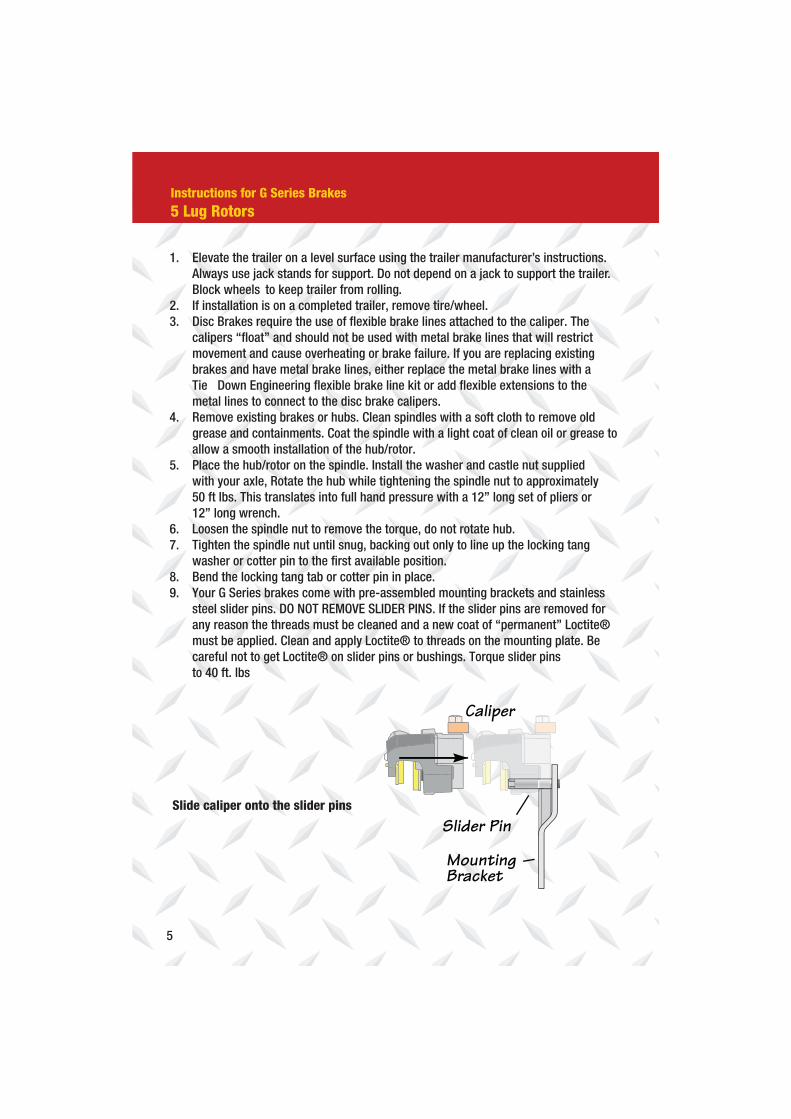
Caliper
MountingBracket
Slider Pin
1. Elevate the trailer on a level surface using the trailer manufacturer’s instructions.
Always use jack stands for support. Do not depend on a jack to support the trailer.
Block wheels to keep trailer from rolling.
2. If installation is on a completed trailer, remove tire/wheel.
3. Disc Brakes require the use of flexible brake lines attached to the caliper. The
calipers “float” and should not be used with metal brake lines that will restrict
movement and cause overheating or brake failure. If you are replacing existing
brakes and have metal brake lines, either replace the metal brake lines with a
Tie Down Engineering flexible brake line kit or add flexible extensions to the
metal lines to connect to the disc brake calipers.
4. Remove existing brakes or hubs. Clean spindles with a soft cloth to remove old
grease and containments. Coat the spindle with a light coat of clean oil or grease to
allow a smooth installation of the hub/rotor.
5. Place the hub/rotor on the spindle. Install the washer and castle nut supplied
with your axle, Rotate the hub while tightening the spindle nut to approximately
50 ft lbs. This translates into full hand pressure with a 12” long set of pliers or
12” long wrench.
6. Loosen the spindle nut to remove the torque, do not rotate hub.
7. Tighten the spindle nut until snug, backing out only to line up the locking tang
washer or cotter pin to the first available position.
8. Bend the locking tang tab or cotter pin in place.
9. Your G Series brakes come with pre-assembled mounting brackets and stainless
steel slider pins. DO NOT REMOVE SLIDER PINS. If the slider pins are removed for
any reason the threads must be cleaned and a new coat of “permanent” Loctite®
must be applied. Clean and apply Loctite® to threads on the mounting plate. Be
careful not to get Loctite® on slider pins or bushings. Torque slider pins
to 40 ft. lbs
Slide caliper onto the slider pins
Instructions for G Series Brakes
5 Lug Rotors
6
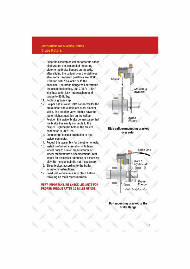
Bolt & Nyloc Nut
Bolt &Nyloc Nut
BrakeFlange
Brake Line
Bolt mounting bracket to the
brake flange
10. Slide the assembled caliper onto the slider
pins. Attach the assembled mounting
plate to the brake flanges on the axle,
after sliding the caliper over the stainless
steel rotor. Preferred positions are 12:00,
9:00 and 3:00 “o-clock” or to the
backside. The brake flange will determine
the exact positioning. Use 7/16”x 1-1/4”
zinc hex bolts, lock nuts/washers and
torque to 40 ft. lbs.
11. Replace grease cap.
12. Caliper has a swivel inlet connector for the
brake hose and a stainless steel bleeder
valve. The bleeder valve should have the
top or highest position on the caliper.
Position the swivel brake connector so that
the brake line easily connects to the
caliper. Tighten the bolt on the swivel
connector to 20 ft. lbs.
13. Connect the flexible brake line to the
swivel connector.
14. Repeat this assembly for the other wheels.
15. Install tire/wheel assembly(s), tighten
wheel nuts to Trailer manufacturer or
wheel manufacture’s specifications. Test
wheel for excessive tightness or excessive
play. Re-tension spindle nut if necessary.
16. Bleed brakes according to the trailer
actuator’s instructions.
17. Road test vehicle in a safe place before
traveling on main roads in traffic.
VERY IMPORTANT, RE-CHECK LUG NUTS FOR
PROPER TORQUE AFTER 25 MILES OF USE.
Caliper
BrakeFlange
MountingBracket
Slide caliper/mounting bracket
over rotor
Instructions for G Series Brakes
5 Lug Rotors
7
Instructions for “G” Series Brakes
6 Lug Rotors
1. Elevate the trailer on a level surface using the trailer manufacturer’s instructions.
Always use jack stands for support. Do not depend on a jack to support the trailer.
Block wheels to keep trailer from rolling.
2. If installation is on a completed trailer, remove tire/wheel.
3. Disc Brakes require the use of flexible brake lines attached to the caliper. The
calipers “float” and should not be used with metal brake lines that will restrict
movement and cause overheating or brake failure. If you are replacing existing
brakes and have metal brake lines, either replace the metal brake lines with a Tie
Down Engineering flexible brake line kit or add flexible extensions to the metal lines
to connect to the disc brake calipers.
4. Remove existing brakes or hubs. Clean spindles with a soft cloth to remove old
grease and containments. Coat the spindle with a light coat of clean oil or grease to
allow a smooth installation of the hub/rotor.
5. Disconnect existing brake line. Elevate the end of the brake hose to keep brake fluid
from draining out.
6. Remove the bolts and nuts holding the caliper-mounting bracket to the brake
flange of the axle. You will re-use the mounting bracket spacer to install the new
G Series caliper.
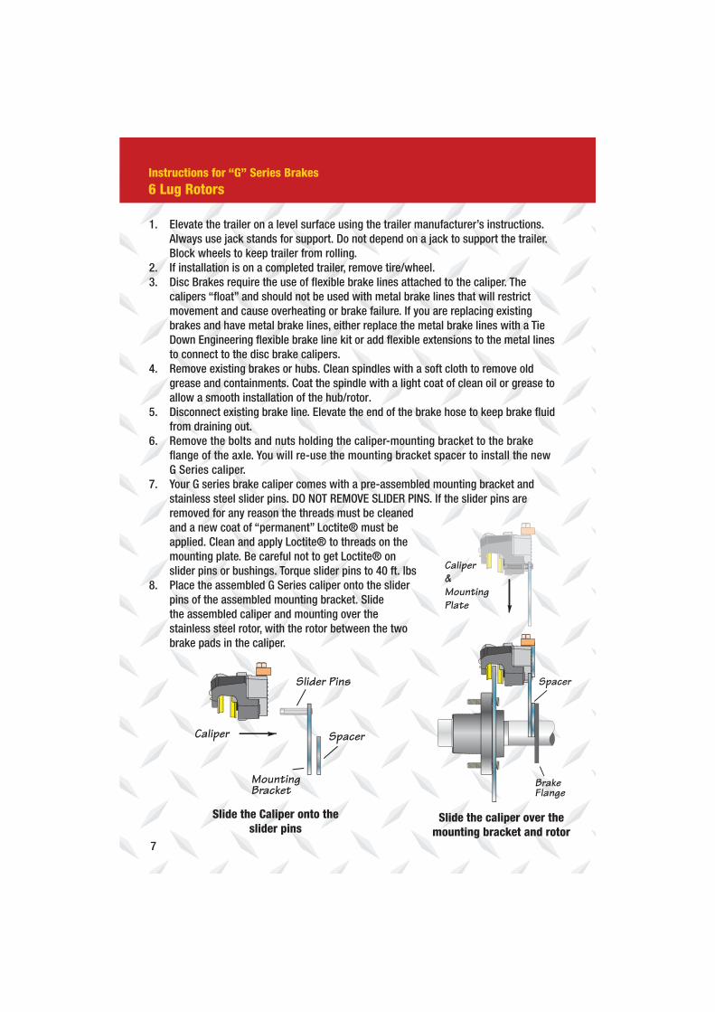
7. Your G series brake caliper comes with a pre-assembled mounting bracket and
stainless steel slider pins. DO NOT REMOVE SLIDER PINS. If the slider pins are
removed for any reason the threads must be cleaned
and a new coat of “permanent” Loctite® must be
applied. Clean and apply Loctite® to threads on the
mounting plate. Be careful not to get Loctite® on
slider pins or bushings. Torque slider pins to 40 ft. lbs
8. Place the assembled G Series caliper onto the slider
pins of the assembled mounting bracket. Slide
the assembled caliper and mounting over the
stainless steel rotor, with the rotor between the two
brake pads in the caliper.
MountingBracket
Spacer
Slider Pins
Caliper
Spacer
BrakeFlange
Caliper&MountingPlate
Slide the Caliper onto the
slider pinsSlide the caliper over the
mounting bracket and rotor
8
Spacer
Bolts &Nyloc Nuts
Swivel BrakeLine Connector
Brake Line
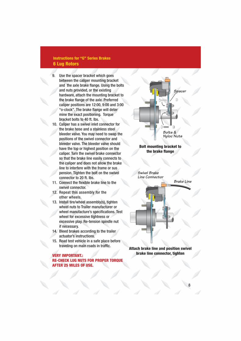
Bolt mounting bracket to
the brake flange
Attach brake line and position swivel
brake line connector, tighten
Instructions for “G” Series Brakes
6 Lug Rotors
9. Use the spacer bracket which goes
between the caliper mounting bracket
and the axle brake flange. Using the bolts
and nuts provided, or the existing
hardware, attach the mounting bracket to
the brake flange of the axle. Preferred
caliper positions are 12:00, 9:00 and 3:00
“o-clock”. The brake flange will deter
mine the exact positioning. Torque
bracket bolts to 40 ft. lbs.
10. Caliper has a swivel inlet connector for
the brake hose and a stainless steel
bleeder valve. You may need to swap the
positions of the swivel connector and
bleeder valve. The bleeder valve should
have the top or highest position on the
caliper. Turn the swivel brake connector
so that the brake line easily connects to
the caliper and does not allow the brake
line to interfere with the frame or sus
pension. Tighten the bolt on the swivel
connector to 20 ft. lbs.
11. Connect the flexible brake line to the
swivel connector.
12. Repeat this assembly for the
other wheels.
13. Install tire/wheel assembly(s), tighten
wheel nuts to Trailer manufacturer or
wheel manufacture’s specifications. Test
wheel for excessive tightness or
excessive play. Re-tension spindle nut
if necessary.
14. Bleed brakes according to the trailer
actuator’s instructions.
15. Road test vehicle in a safe place before
traveling on main roads in traffic.
VERY IMPORTANT.:
RE-CHECK LUG NUTS FOR PROPER TORQUE
AFTER 25 MILES OF USE.
9
Replacement of Brake Pads
1. Elevate the trailer on a level surface using the trailer manufacturer’s instructions.
Always use jack stands for support. Do not depend on a jack to support the trailer.
Block wheels to keep trailer from rolling.
2. Remove the tire/wheel assembly. Inspect the rotor surface. Check for excessive
wear or grooves that may affect braking.
3. Inspect brake pads. Minimum thickness is 3/32”. Pads should be replaced if less
then minimum thickness.
4. Remove the caliper by first removing the mounting bolts from the mounting bracket
and brake flange. Lift the mounting bracket and caliper assembly off of the rotor. Be
careful to hold the caliper in place so that it does not fall and pull on the brake hose.
The inside pad is spring loaded in the caliper piston. Pry this pad out gently with a
flat blade screwdriver. The outside pad is held in place with a center mounted
spring tab. After removing the inside pad, the outside pad can be pulled from
the caliper.
5. Clean the rotor with a brake cleaning spray. Replace brake pads in the reverse
order. For ease of assembly, make sure the piston in the caliper is fully depressed
into the caliper.
6. Re-attach the mounting bracket to the axle brake flange, sliding the caliper over the
rotor. Tighten the four mounting bracket bolts. Torque bolts to 40 lbs.
7. Should you remove the slider pins for any reason, clean the threads on the slider
bolts and mounting plate and apply a coating of Loctite
or similar brand of thread lock. Tighten slider pins to 40 ft lbs. DO NOT
REASSEMBLE WITHOUT APPLYING LOCTITE® TO THE SLIDER PIN THREADS AND
THE BACKING PLATE. SLIDER PINS WITHOUT LOCKTITE® APPLIED COULD
BACK OUT AND CAUSE PERMANENT DAMAGE TO YOUR BRAKES AND TRAILER.
10
Removing the Hub/Rotor
1. The G Series Stainless Steel Disc Brake have an integral style rotor. Hub and rotor
are assembled as one piece, and will come off as one.
2. Elevate the trailer on a level surface using the trailer manufacturer’s instructions.
Always use jack stands for support. Do not depend on a jack to support the trailer.
Block wheels to keep trailer from rolling.
3. Remove the tire/wheel assembly.
4. Remove the caliper by removing the mounting bolts from the mounting bracket
and brake flange. Lift the mounting bracket and caliper assembly as one unit, off
of the rotor. Be careful to hold the caliper in place so that it does not fall and pull
on the brake hose. Support the caliper and mounting bracket so that it does not
“hang” from the brake line.
5. Remove the grease cap from the hub by prying around the edge of the cap.
6. Bend the locking tang washer to the “free” position. If spindle is equipped with a
cotter key, straighten cotter key to remove.
7. Remove the spindle nut in a counter clockwise direction and remove the
spindle washer.
8. Remove the hub from the spindle. Be careful not to allow bearings to fall out
of the hub.
9. Clean bearing and cup surfaces, repack with lithium marine grade grease.
10. Place hub on spindle in reverse order as listed above. Rotate the hub while
tightening the spindle nut to approximately 50 ft lbs. This translates into full hand
pressure with a 12” long set of pliers or 12” long wrench.
11. Loosen the spindle nut to release the torque, do not rotate hub.
12. Tighten the spindle nut until snug, backing out only to line up the locking tang
washer or cotter pin.
13. Bend the locking tang tab or cotter pin in place.
14. Re-attach the mounting bracket to the axle brake flange, sliding the caliper over the
rotor. Tighten the four mounting bracket bolts.
15. Should you remove the caliper slider bolts for any reason, clean the threads of the
slider bolts & mounting bracket and apply a fresh coating of Loctite® to the pins as
well as the mounting bracket. Tighten pins to 40 ft lbs. DO NOT REASSEMBLE
WITHOUT APPLYING LOCTITE® TO THE SLIDER PIN THREADS AND THE BACKING
PLATE. SLIDER PINS WITHOUT LOCTITE® APPLIED COULD BACK OUT AND CAUSE
PERMANENT DAMAGE TO YOUR BRAKES AND TRAILER.
16. Replace cap. Install tire/wheel assembly, tighten wheel nuts to Trailer manufacturer
or wheel manufacture’s specifications. Test wheel for excessive tightness or
excessive play. Readjust in necessary.
17. Road test vehicle in a safe place before traveling on main roads in traffic.
VERY IMPORTANT:
RE-CHECK LUG NUTS FOR PROPER TORQUE AFTER 25 MILES OF USE.
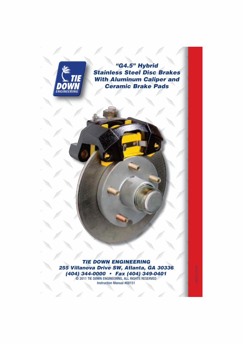
TIE DOWN ENGINEERING
255 Villanova Drive SW, Atlanta, GA 30336
© 2011 TIE DOWN ENGINEERING, ALL RIGHTS RESERVED
Instruction Manual #08151
“G4.5” Hybrid
Stainless Steel Disc Brakes
With Aluminum Caliper and
Ceramic Brake Pads
06
2711
,C11
98