Embed Size (px)
Citation preview
1
G9TA
G9TAAC Power Latching Relay
60 A High power latching relay• High power switching, Compact size
• High magnetic latching force provides vibration resistance
• Low contact resistance
• PCB terminals type available
• Conforms to UL 508 (Except PCB terminals type)
Ordering Information
Note. When ordering, add the rated coil voltage to the model number. Example: G9TA-U1ATH DC12
Rated coil voltageHowever, the notation of the coil voltage on the product case as well as on the packing will be marked as[][] VDC.
Ratings CoilSingle-winding Latching Type
Double-winding Latching Type
Note 1. The rated current and coil resistance were measured at a coil temperature of 23°C with tolerances of ± 10%.Note 2. The operating characteristics are measured at a coil temperature of 23°C.Note 3. The maximum permissible voltage is the maximum value of the fluctuation range for the Relay coil operating power supply and was measured at an ambient
temperature of 23°C.
Contacts
RoHS Compliant
Classification Contact Form Terminal Shape Enclosure rating Model Rated coil voltage Minimum packing unit
Single coil
SPST-NO
M5 securing screw
Flux protection
G9TA-U1ATH12 VDC
25 pcs/tray
Welding terminals G9TA-U1ATWPCB terminals G9TA-U1AP
Double coilsM5 securing screw G9TA-K1ATH
12 VDCWelding terminals G9TA-K1ATWPCB terminals G9TA-K1AP
ItemRated current (mA) Coil resistance (Ω)
Must set voltage Must reset voltage Max. voltage Power consumption
Rated Voltage (V) % of rated voltage Set coil (W) Reset coil (W)DC 12 83 145 80% max. 80% max. 110% max. Approx. 1.0
Item Rated current (mA) Coil resistance (Ω) Must set voltage Must reset voltage Max. voltage Power consumption
Rated Voltage (V) Set coil Reset coil Set coil Reset coil % of rated voltage Set coil (W) Reset coil (W)DC 12 217 217 55 55 80% max. 80% max. 110% max. Approx. 2.6 Approx. 2.6
Model G9TA-U1A /G9TA-K1AItem Load Resistive load Inductive load (PF=0.5)Contact type SPST-NOContact material Ag AlloyRated load 60 A at 250 VACRated carry current 60 AMax. switching voltage 250 VACMax. switching current 60 A
Model Number Structure
G9TA- 1 A
1. Relay FunctionU: Single-winding latchingK: Double-winding latching
1 2 3
2. Number of poles1: 1-Pole
4
3. Contact FormA: SPST-NO
4. Terminal shapeTH: M5 securing screwTW: Welding terminalsP: PCB terminals
Application Examples• Smart Meter • Lighting control• PV Inverter • EV Charger
2
G9TA AC Power Latching Relay
G9TA
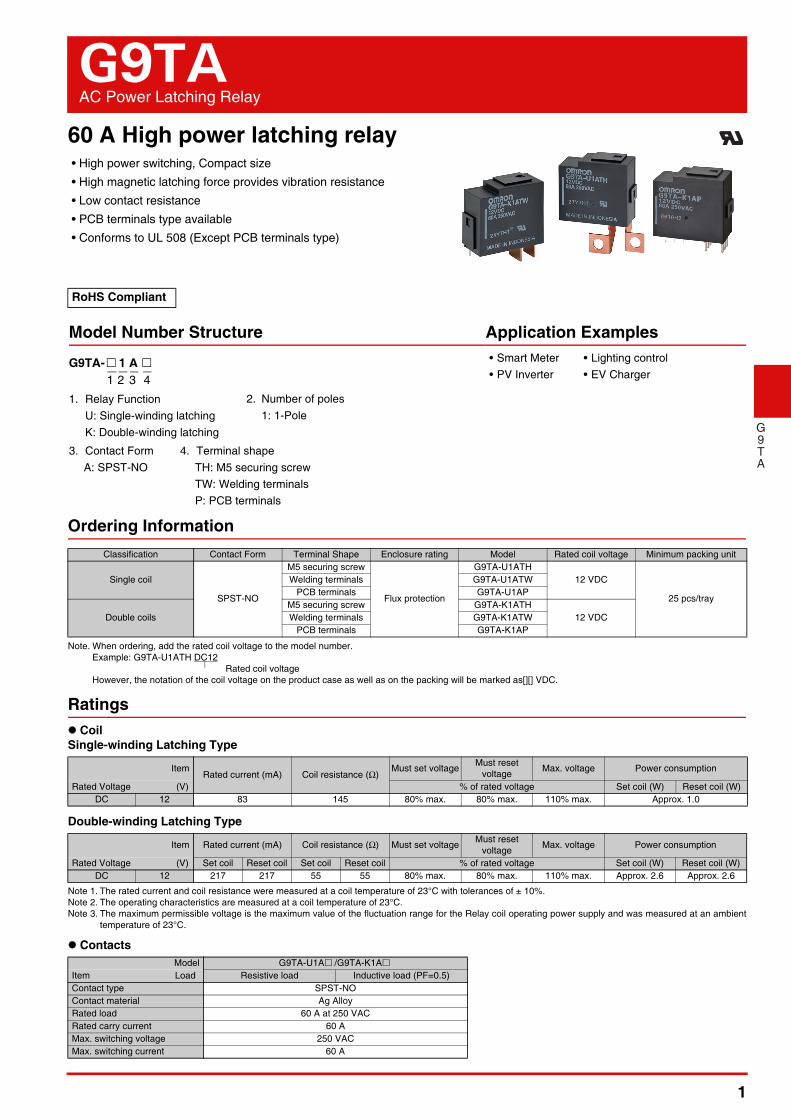
Characteristics
Note. The values given above are initial values.*1. Measurement conditions: 24 VDC, 1 A, voltage drop method.*2. Measurement conditions: Rated operating voltage applied, not including contact bounce.
Ambient temperature: 23°C*3. Measurement conditions: The insulation resistance was measured with a 500 VDC megohm meter at the same locations as the dielectric strength was measured.*4. Contact your OMRON sales representative for Electrical Durability technical data.*5. The characteristic meets IEC62055-31 test requirement.
Item G9TA-U1A G9TA-K1A
Contact resistance *1 2 mΩ max.
Set time *2 30 ms max. 20 ms max.
Reset time *2 30 ms max. 20 ms max.
Minimum pulse width 100 ms
Maximum pulse width 1,000 ms
Insulation resistance *3 1,000 MΩ min.
Dielectric strengthBetween coil and contacts 4,000 VAC, 50/60 Hz for 1 min
Between contacts of the same polarity 1,500 VAC, 50/60 Hz for 1 min
Impulse withstand voltage Between coil and contacts 6 kV
Vibration resistanceDestruction 10 to 150 to 10 Hz, f < 60 Hz: Constant amplitude 0.075 mm, f > 60 Hz: Constant acceleration 9.8 m/s2
Malfunction 10 to 55 to 10 Hz, 0.75 mm single amplitude (1.5 mm double amplitude)
Shock resistanceDestruction 1,000 m/s2
Malfunction 100 m/s2
DurabilityMechanical 100,000 operations min. (at 7,200 operations/h)
Electrical *4 5,000 operations, resistive load and then5,000 operations, inductive load (PF=0.5) (operation: ON for 10 sec, OFF for 20 sec) *5
Ambient operating temperature -40 to 85°C (with no icing or condensation)
Ambient operating humidity 5 to 85%
Weight Approx. 42 g
3
G9TA AC Power Latching Relay
G9TA
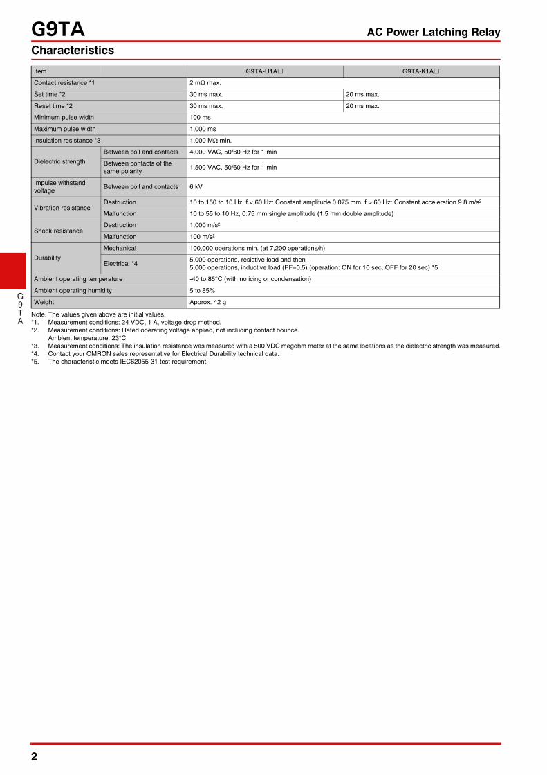
Dimensions (Unit: mm) Please visit our website, which is noted on the last page.CAD Data
39.1 max.
34.5 max.
5 9.9
4.95
5 10
30
4
6.7
4
Two, �5.5 dia.9.3
10
4.65
3.7
18.55
3.7 1
7.7
1
5±0.05
14.2 18 max.
Two, �0.64±0.01
431 2
SR
--
Terminal arrangement/Internal Connections(TOP VIEW)
Check carefully the coil polarity of the Relay.
G9TA-U1ATH
CAD Data
12 10.6
39.1 max.
34.5 max.
8.8
30
4
1 1
14.218 max.
Two, �0.64±0.0118.557.7
5±0.05
Check carefully the coil polarity of the Relay.
Terminal arrangement/Internal Connections(TOP VIEW)
RS -
-321 4
G9TA-U1ATW
CAD Data
Check carefully the coil polarity of the Relay.
Terminal arrangement/Internal Connection(BOTTOM VIEW)
PCB Mounting Holes(BOTTOM VIEW)
431 2SR
--
6-1.5
5.5
39.1 max. 18 max.
36.7 max.
Two, �0.64
30
1 1
5±0.1
0.6±0.1
8.7±0.1
4±0.1
4±0.1
19.05±0.1
Two, �1.2±0.1
Six, �2±0.1
(2.8)
(3.4)
8.7 5 4 419.05
G9TA-U1AP
CAD Data

4
G9TA AC Power Latching Relay
G9TA
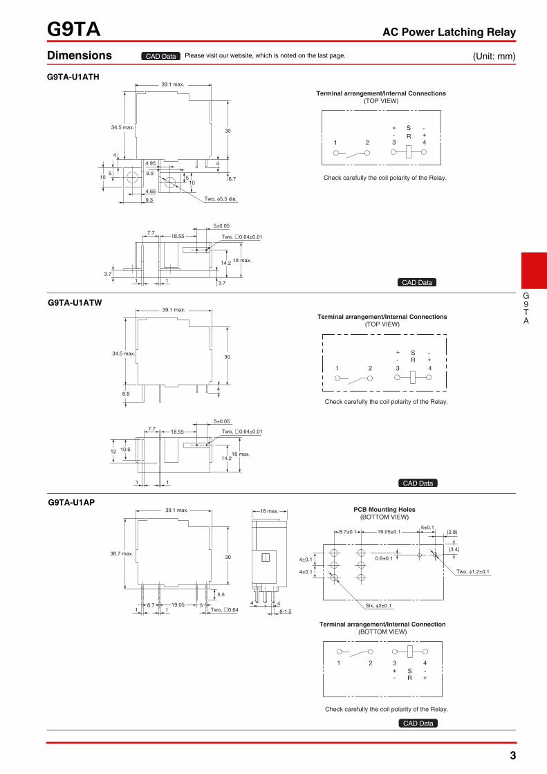
(Unit: mm)
Note 1. Relay is delivered as "reset" status unless specified otherwise. However, the status may change due to the shock from transportation or mounting operations.Therefore, it is recommended the relay should be set to the expected status via a power supply before being used.
Note 2. In order to maintain "set" or "reset" status, the energizing voltage to coil & the pulse width shouldn't lower then the rated value.Note 3. Do not energize both of set and reset coil simultaneously.Note 4. Energizing time longer than 1,000 ms should be avoided.
10
39.1 max.
34.5 max.
5
9.3
3.7
13.55
10 5
3.7
30
4
4.65
9.9
4.95
6.7
Two, �5.5 dia.
4
1
7.7
1
5±0.05 5±0.05
14.218 max.
Three, �0.64±0.01
Check carefully the coil polarity of the Relay.
4 51 2 3S R-
Terminal arrangement/Internal Connections(TOP VIEW)
G9TA-K1ATH
CAD Data
Check carefully the coil polarity of the Relay.
4 51 2 3S R-
Terminal arrangement/Internal Connections(TOP VIEW)
48.8
39.1 max.
34.5 max.
13.55
30
1
7.7
1
5±0.05 5±0.05
14.218 max.
Three, �0.64±0.01
12 10.6
G9TA-K1ATW
CAD Data
PCB Mounting Holes(BOTTOM VIEW)
Check carefully the coil polarity of the Relay.
4 51 2 3S R-
Terminal arrangement/Internal Connections(BOTTOM VIEW)
5.5
39.1 max.
36.7 max.
Three, �0.64
30
1 18.7 14.05
5 56-1.5
18 max.
4 4
5±0.15±0.1
0.6±0.1
8.7±0.1
4±0.1
4±0.1
14.05±0.1
Three, �1.2±0.1
Six, �2±0.1
(2.8)
(3.4)
G9TA-K1AP
CAD Data

5
G9TA AC Power Latching Relay
G9TA
Engineering Data
Approved StandardsThe approval rating values for overseas standards are different from the performance values determined individually. Confirm the valuesbefore use. UL Recognized: (File No. E41515)
Safety Precautions• Please refer to "PCB Relays Common Precautions" for correct use.
Installation• The relay contacts are polarized. Incorrect wiring may cause a
failure to break the circuit. Wire the Relay with care.• Install the Relays in locations that are as dry as possible and
have as little dust, dirt, and harmful gas.• Using the Relay under high temperature, high humidity, or
harmful gas may deteriorate its performance characteristics due to condensation or corrosive materials, resulting in failure or burn damage to the Relay.
Relay Service Life• The electrical durability of these Relays is specified as the
number of load switching operations under a resistive load and OMRON-specified standard testing conditions.The coil drive circuit, ambient environment, switching frequency, or load conditions (e.g., inductive load or capacitor load) may reduce the service life and possibly lead to failure to break. Always confirm the service life in the actual equipment.
Wiring• Be sure to tighten all screws to the appropriate torque given below.• Loose screws may result in burning due to abnormal heat generation during energization.• M5 screws: 1.57 to 2.35 N·m• Use a spring washer in order to prevent deformation and looseness.• Allow suitable slack on leads when wiring, and do not apply excessive force to the terminals.
Maximum Switching CapacityG9TA-U1A
G9TA-K1A
Model Contact form Coil ratings Contact ratings Number of test operations
G9TA-U1ATHG9TA-U1ATWG9TA-K1ATWG9TA-K1ATH
SPST-NO (1a) 12V DC
60 A, 277 V AC (Resistive) 70°C 6,000
60 A, 250 V AC (Resistive) and then 60 A,250 V (PF=0.5), 10 sec. ON / 20 sec. OFF, 40°C
5,000 for resistive and then5,000 for PF=0.5
Correct Use
Switching voltage (V)
Sw
itchi
ng c
urre
nt (
A)
1
10
100
1000
1 10 100 1000
AC Resistive Load60
250Switching voltage (V)
Sw
itchi
ng c
urre
nt (
A)
1
10
100
1000
1 10 100 1000
AC Inductive Load (PF=0.5)60
250
Please check each region's Terms & Conditions by region website.
OMRON CorporationElectronic and Mechanical Components Company
Regional Contact
Cat. No. J220-E1-030120(0318)
Americas Europehttps://www.components.omron.com/ http://components.omron.eu/
Asia-Pacific China https://ecb.omron.com.sg/ https://www.ecb.omron.com.cn/
Korea Japanhttps://www.omron-ecb.co.kr/ https://www.omron.co.jp/ecb/
In the interest of product improvement, specifications are subject to change without notice.© OMRON Corporation 2018-2020 All Rights Reserved.