Embed Size (px)
Citation preview

All rights reserved. No parts of this work may be reproduced in any form or by any means - graphic, electronic, ormechanical, including photocopying, recording, taping, or information storage and retrieval systems - without the writtenpermission of the publisher.
Products that are referred to in this document may be either trademarks and/or registered trademarks of the respectiveowners. The publisher and the author make no claim to these trademarks.
While every precaution has been taken in the preparation of this document, the publisher and the author assume noresponsibility for errors or omissions, or for damages resulting from the use of information contained in this document orfrom the use of programs and source code that may accompany it. In no event shall the publisher and the author be liablefor any loss of profit or any other commercial damage caused or alleged to have been caused directly or indirectly by thisdocument.
Printed: Sunday, March 04, 2012 at 8:26 AM in Sunriver, Oregon.
GageWay SM
Copyright © 2006-2012 MicroRidge Systems, Inc.

IContents
Copyright © 2006-2012 MicroRidge Systems, Inc.
GageWay SM
Table of Contents
Chapter 1 1...................................................................................................................................Introduction
...................................................................................................................................Why do I Need an Interface? 2
...................................................................................................................................My Computer Does Not Have a Serial Port 2
Chapter 2 3...................................................................................................................................Driver Installation for USB Version
Chapter 3 4...................................................................................................................................Operation
...................................................................................................................................How the GageWay SM is Powered 4
...................................................................................................................................Read Switch Connector 4
...................................................................................................................................Computer Commands 5
...................................................................................................................................Output Data Format 5
Chapter 4 6...................................................................................................................................ComTestSerial
Chapter 5 7...................................................................................................................................Accessories
Chapter 6 8...................................................................................................................................Warranty Information
Chapter 7 9...................................................................................................................................Contact MicroRidge
Introduction 1
Copyright © 2006-2012 MicroRidge Systems, Inc.
GageWay SM
1 Introduction
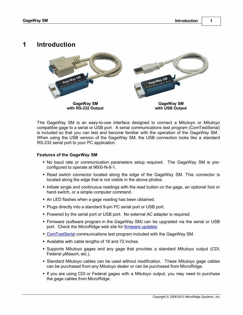
GageWay SMwith RS-232 Output
GageWay SMwith USB Output
The GageWay SM is an easy-to-use interface designed to connect a Mitutoyo or Mitutoyocompatible gage to a serial or USB port. A serial communications test program (ComTestSerial)is included so that you can test and become familiar with the operation of the GageWay SM. When using the USB version of the GageWay SM, the USB connection looks like a standardRS-232 serial port to your PC application.
Features of the GageWay SM
No baud rate or communication parameters setup required. The GageWay SM is pre-configured to operate at 9600-N-8-1.
Read switch connector located along the edge of the GageWay SM. This connector islocated along the edge that is not visible in the above photos.
Initiate single and continuous readings with the read button on the gage, an optional foot orhand switch, or a simple computer command.
An LED flashes when a gage reading has been obtained.
Plugs directly into a standard 9-pin PC serial port or USB port.
Powered by the serial port or USB port. No external AC adapter is required.
Firmware (software program in the GageWay SM) can be upgraded via the serial or USBport. Check the MicroRidge web site for firmware updates.
ComTestSerial communications test program included with the GageWay SM.
Available with cable lengths of 18 and 72 inches.
Supports Mitutoyo gages and any gage that provides a standard Mitutoyo output (CDI,Federal µMaxum, etc.).
Standard Mitutoyo cables can be used without modification. These Mitutoyo gage cablescan be purchased from any Mitutoyo dealer or can be purchased from MicroRidge.
If you are using CDI or Federal gages with a Mitutoyo output, you may need to purchasethe gage cables from MicroRidge.

Introduction 2
Copyright © 2006-2012 MicroRidge Systems, Inc.
GageWay SM
1.1 Why do I Need an Interface?We often get asked “Why do I need to purchase a gage interface to connect my gage to a PC?” The Mitutoyo compatible gages use a signaling method referred to as clocked serial.
The clocked serial data is not sent at a constant rate like RS-232 data; therefore, the Mitutoyosignals require special signal processing to convert them into a standard RS-232 format. Remember that when using the USB version of the GageWay SM, the USB drivers that youinstall make the GageWay SM output look like a regular RS-232 serial port to your PCapplication.
There are a few calipers and digital indicators that have an RS-232 output; however, one shouldcarefully analyze the cost before purchasing the RS-232 ready devices.
You must consider the gage cables to be a consumable item, and factor gage cable replacementinto the cost of your measurement system. People have reported that gage cable consumablerates may be measured in days, weeks or months. Another limitation with RS-232 ready devicesis that the range of products available is small when compared to the products with a Mitutoyocompatible output.
1.2 My Computer Does Not Have a Serial PortThis topic is only pertinent if you are trying to connect an RS-232 version of the GageWay SM toyour PC. If you have purchased the RS-232 version and really need the USB version, contactyour dealer or MicroRidge Systems.
Many of the computers that are being sold today do not contain any RS-232 serial ports. If yourcomputer does not have any serial ports, it will have several USB ports. You will need to obtaina USB to serial converter cable in order to connect the RS-232 version of the GageWay SM toyour PC. This cable will convert one of your USB ports to a serial port. These USB to serialcables are available directly from MicroRidge Systems.
Driver Installation for USB Version 3
Copyright © 2006-2012 MicroRidge Systems, Inc.
GageWay SM
2 Driver Installation for USB VersionBefore you connect the USB version of the GageWay SM to your PC, you must install the USBand virtual serial port drivers. These drivers are located on the CD that you received with theGageWay SM. After installing the drivers, connect the GageWay SM to a USB port. Once theGageWay SM is connected, you will get a message about new hardware found.
USB Driver Installation
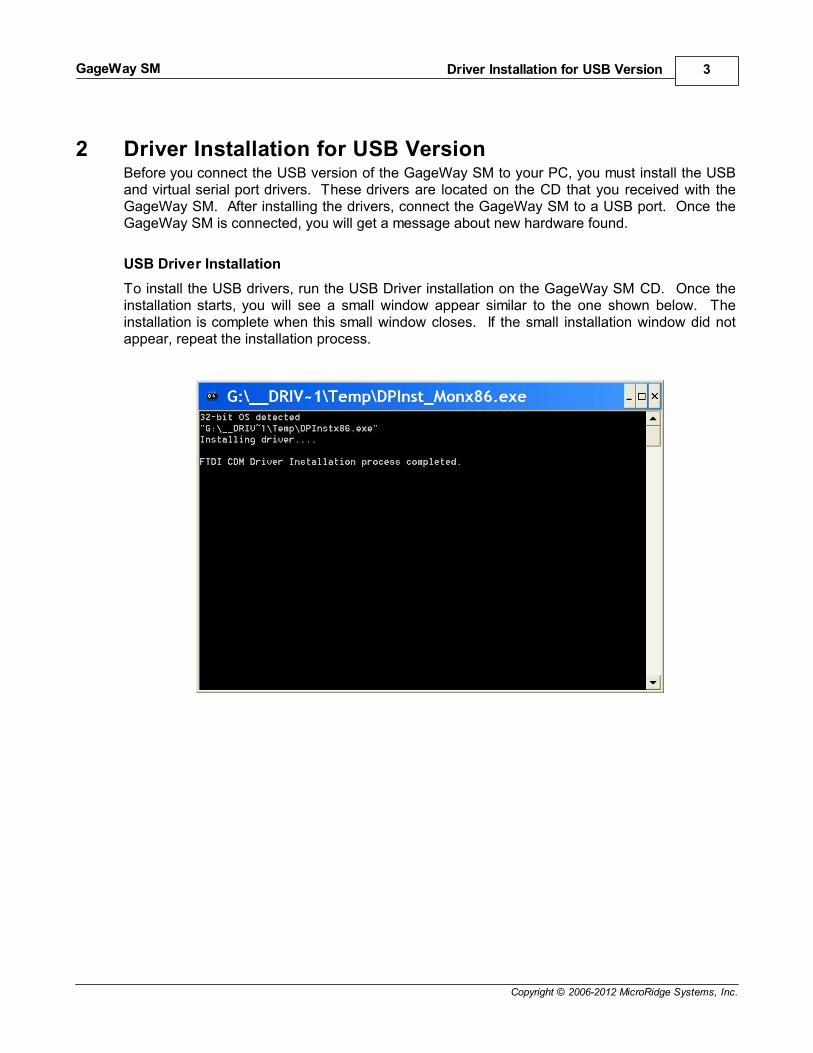
To install the USB drivers, run the USB Driver installation on the GageWay SM CD. Once theinstallation starts, you will see a small window appear similar to the one shown below. Theinstallation is complete when this small window closes. If the small installation window did notappear, repeat the installation process.

Operation 4
Copyright © 2006-2012 MicroRidge Systems, Inc.
GageWay SM
3 OperationTo become familiar with the operation of the GageWay SM, we suggest you follow the stepsoutlined below. You can check communications with the GageWay SM even if you do not havea gage connected to the interface.
Connect the GageWay SM to a serial or USB port. If you have purchased a GageWay SMwith an RS-232 connector and do not have a serial port on your PC, refer to My ComputerDoes Not Have a Serial Port.
Start the ComTestSerial communications program.
Press the Setup button and select the GageWay SM command set.
If necessary, change the serial port number by pressing the Serial Port button. TheRegistry Description in the Select & Configure Serial Port dialog for the USB version willhave a description similar to \Device\VCP0. In order to use the USB version, you mustselect the virtual serial port that was created for the currently connected GageWay SM. The baud rate and communication parameters must be set to 9600-N-8-1.
Use the Computer Commands or the command buttons at the bottom of the ComTestSerialwindow to test the communications with the GageWay SM.
When the GageWay SM is powered up, the LED will blink about 6 times. When theblinking stops, the GageWay SM is ready to receive commands and send data to the PC.
The RS-232 version of the GageWay SM is powered by the serial port handshake lines. Powerup and power down of the GageWay SM is performed by the application controlling the serialport handshake lines. Refer to How the GageWay SM is Powered for more details.
The USB version of the GageWay SM is powered by the USB port and will be powered up whenthe GageWay SM is connected to a USB port.
3.1 How the GageWay SM is PoweredThe RS-232 version of the GageWay SM is designed to draw its power from the serial port anddoes not require an external AC adapter. On the standard serial port there are 2 handshakelines that can be used to supply power to devices that have very low power needs. On thestandard 9-pin PC serial port, the 2 pins that are used are pin 4 (DTR) and pin 7 (RTS). In orderfor your application to use the GageWay SM-R, one or both of these pins must be high. Typically when an application opens a serial port, the application sets both of these lines to thehigh state. You can manually set these handshake lines high and low when testing theGageWay SM with the ComTestSerial communications program.
The USB version of the GageWay SM is powered directly by the USB port and it does notmatter whether the handshake lines are high or low.
3.2 Read Switch ConnectorThe GageWay SM contains a read switch connector along the edge of the unit. Gages such ascalipers and micrometers will have a read switch on the gage cable and a separate read switchis typically not required. If you are using a digital indicator with the GageWay SM, you will needto use an external read switch or send a computer command from your PC.

Operation 5
Copyright © 2006-2012 MicroRidge Systems, Inc.
GageWay SM
The read switch provides a contact closure to tell the GageWay SM to get a gage reading. Youcan purchase a read switch from MicroRidge (see Accessories) or build your own. The requiredread switch connector is a 2.5 mm mono phone plug.
3.3 Computer CommandsThe GageWay SM can be controlled with a set of computer commands. You should test thesecommands with ComTestSerial so that you fully understand the response and the format of theresponse.
The user commands that consist of a letter can be upper or lower case. To request a readingyou can send R or r. A carriage return (enter key) is not required at the end of any of thecommands. If you send an invalid command, the command will be discarded by the GageWaySM.
User commands (commands can be upper or lower case):
R Read gage.
B Begin continuous gage read.
S Stop continuous gage read.
C Begin continuous gage read when read switch (foot switch, hand switch, readbutton on gage, etc.) is pressed and held.
D Stop (disable) continuous gage read when the read switch is released.
H Display a list of the computer commands.
L Turn the LED on for 50 milliseconds (msec).
V Version information.
Z Reset to power up configuration. This will also disable the continuous read thatwas controlled by a remote read switch. The LED will flash 4 times when thiscommand is received.
* Copyright information.
3.4 Output Data FormatThe data format of a reading from a Mitutoyo device is fixed and cannot be modified by the user. The GageWay SM sends the measurement left justified and the measurement is terminated witha carriage return. There are no leading, trailing or embedded blanks in the measurement string. The length of the measurement string will vary based on the number of digits in themeasurement. A few examples are shown below.
1.3265
.1455
-.5725
13.26
ComTestSerial 6
Copyright © 2006-2012 MicroRidge Systems, Inc.
GageWay SM
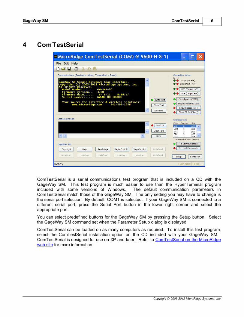
4 ComTestSerial
ComTestSerial is a serial communications test program that is included on a CD with theGageWay SM. This test program is much easier to use than the HyperTerminal programincluded with some versions of Windows. The default communication parameters inComTestSerial match those of the GageWay SM. The only setting you may have to change isthe serial port selection. By default, COM1 is selected. If your GageWay SM is connected to adifferent serial port, press the Serial Port button in the lower right corner and select theappropriate port.
You can select predefined buttons for the GageWay SM by pressing the Setup button. Selectthe GageWay SM command set when the Parameter Setup dialog is displayed.
ComTestSerial can be loaded on as many computers as required. To install this test program,select the ComTestSerial installation option on the CD included with your GageWay SM. ComTestSerial is designed for use on XP and later. Refer to ComTestSerial on the MicroRidgeweb site for more information.
Accessories 7
Copyright © 2006-2012 MicroRidge Systems, Inc.
GageWay SM
5 AccessoriesSeveral accessories are available for use with GageWay SM.
Purchase On the Web
These items are available for purchase directly from the MicroRidge web site at the GageWayInterface Store.
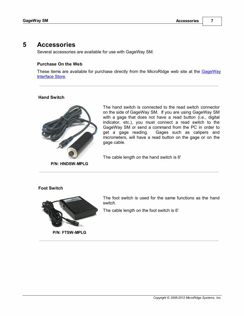
Hand Switch
P/N: HNDSW-MPLG
The hand switch is connected to the read switch connectoron the side of GageWay SM. If you are using GageWay SMwith a gage that does not have a read button (i.e., digitalindicator, etc.), you must connect a read switch to theGageWay SM or send a command from the PC in order toget a gage reading. Gages such as calipers andmicrometers, will have a read button on the gage or on thegage cable.
The cable length on the hand switch is 6'
Foot Switch
P/N: FTSW-MPLG
The foot switch is used for the same functions as the handswitch.
The cable length on the foot switch is 6'

Warranty Information 8
Copyright © 2006-2012 MicroRidge Systems, Inc.
GageWay SM
6 Warranty InformationThe standard MicroRidge warranty for products it manufactures and resells is described below:
MicroRidge warrants that equipment manufactured by MicroRidge to be free from defects inmaterial and workmanship, when properly maintained under normal use, for a period oftwelve (12) months from date of purchase of the product (the “warranty period”). Someproducts sold and distributed by MicroRidge are warranted by the manufacturer of theproducts.
Warranty for gage and RS-232 interface cables is 30 days from date of shipment.
Products which do not conform to their description or which are defective in material orworkmanship will, by MicroRidge decision, be replaced or repaired, or, at MicroRidge’soption, credit for the original purchase price may be allowed provided that customer notifiesMicroRidge in writing of such defect within thirty (30) days of discovery and returns suchproducts in accordance with the MicroRidge instructions. No products may be returnedwithout MicroRidge prior written authorization.
This warranty does not apply to any product which has been subjected to misuse, abuse,negligence or accident by the customer.
MicroRidge makes no other warranty or representation of any kind with respect to theproducts, either express or implied, including without limitation, that of merchantability orfitness for a particular use. Failure to make any claim in writing, or within the thirty (30) dayperiod set forth above, shall constitute an irrevocable acceptance of the products and anadmission by the customer that the products fully comply with all terms, conditions andspecifications of customer’s purchase order. MicroRidge shall not be liable for direct,indirect, incidental, special or consequential damages, under any circumstances, including,but not limited to, damage or loss resulting from inability to use the products, increasedoperating costs or loss of sales, or any other damages. To make a claim under thiswarranty, customer must notify MicroRidge in writing within the warranty period.
Customer will pay all shipping charges (and duty and taxes) for equipment returned toMicroRidge for warranty service. MicroRidge will pay shipping charges for equipmentreturned to customer in North America. Customers outside the USA are responsible forduty and taxes on equipment returned to them.
Software developed by MicroRidge is warranted to operate in accordance with the softwaredocumentation on the hardware specified in such documentation, for a period of six (6)months from date of shipment. During the warranty period, MicroRidge will at no chargecorrect any programming error in the software that interferes with normal operation of thesoftware provided that MicroRidge is able to reproduce such error on MicroRidgecomputer.

Contact MicroRidge 9
Copyright © 2006-2012 MicroRidge Systems, Inc.
GageWay SM
7 Contact MicroRidge
Email:
Support: [email protected]
Sales: [email protected]
Information: [email protected]
Phone:
Support: 541.593.1656
Sales: 541.593.3500
Main office: 541.593.1656
Fax: 541.593.5652
Mailing Address:
MicroRidge Systems, Inc.
PO Box 3249
Sunriver, OR 97707-0249
Shipping Address:
MicroRidge Systems, Inc.
56888 Enterprise Drive
Sunriver, OR 97707
Note: There is no mail delivery to this address. This address should only be used forpackage delivery services such as UPS, FedEx, etc.
Web: www.microridge.com