Embed Size (px)
Citation preview
GAIL (India) Limited
TENDER DOCUMENT
FOR
Laying and Construction of 10” x 32 km, Steel Pipeline,Terminals and Associates Facilities for supplying RLNG
from Ibrahimpur to M/s RRVUN LTD at Dholpur,Rajasthan
Vol-II of IV
TENDER NO.: 05/51/23JV/GAIL/001
MECON LIMITEDSCOPE MINAR
15th Floor, North TowerLaxmi Nagar District Centre
DELHI – 110 092July, 2006
D:\old data\FATEH\IDPL_Dholpur\SCC\Final\Content - Vol-II, III & IV.doc
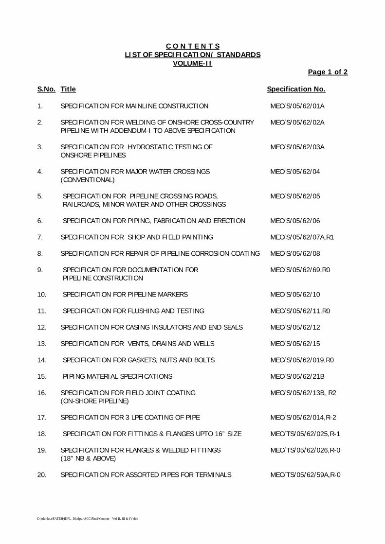
C O N T E N T SLIST OF SPECIFICATION/ STANDARDS
VOLUME-IIPage 1 of 2
S.No. Title Specification No.
1. SPECIFICATION FOR MAINLINE CONSTRUCTION MEC/S/05/62/01A
2. SPECIFICATION FOR WELDING OF ONSHORE CROSS-COUNTRY MEC/S/05/62/02APIPELINE WITH ADDENDUM-I TO ABOVE SPECIFICATION
3. SPECIFICATION FOR HYDROSTATIC TESTING OF MEC/S/05/62/03AONSHORE PIPELINES
4. SPECIFICATION FOR MAJOR WATER CROSSINGS MEC/S/05/62/04(CONVENTIONAL)
5. SPECIFICATION FOR PIPELINE CROSSING ROADS, MEC/S/05/62/05 RAILROADS, MINOR WATER AND OTHER CROSSINGS
6. SPECIFICATION FOR PIPING, FABRICATION AND ERECTION MEC/S/05/62/06
7. SPECIFICATION FOR SHOP AND FIELD PAINTING MEC/S/05/62/07A,R1
8. SPECIFICATION FOR REPAIR OF PIPELINE CORROSION COATING MEC/S/05/62/08
9. SPECIFICATION FOR DOCUMENTATION FOR MEC/S/05/62/69,R0 PIPELINE CONSTRUCTION
10. SPECIFICATION FOR PIPELINE MARKERS MEC/S/05/62/10
11. SPECIFICATION FOR FLUSHING AND TESTING MEC/S/05/62/11,R0
12. SPECIFICATION FOR CASING INSULATORS AND END SEALS MEC/S/05/62/12
13. SPECIFICATION FOR VENTS, DRAINS AND WELLS MEC/S/05/62/15
14. SPECIFICATION FOR GASKETS, NUTS AND BOLTS MEC/S/05/62/019,R0
15. PIPING MATERIAL SPECIFICATIONS MEC/S/05/62/21B
16. SPECIFICATION FOR FIELD JOINT COATING MEC/S/05/62/13B, R2(ON-SHORE PIPELINE)
17. SPECIFICATION FOR 3 LPE COATING OF PIPE MEC/S/05/62/014,R-2
18. SPECIFICATION FOR FITTINGS & FLANGES UPTO 16” SIZE MEC/TS/05/62/025,R-1
19. SPECIFICATION FOR FLANGES & WELDED FITTINGS MEC/TS/05/62/026,R-0(18” NB & ABOVE)
20. SPECIFICATION FOR ASSORTED PIPES FOR TERMINALS MEC/TS/05/62/59A,R-0
D:\old data\FATEH\IDPL_Dholpur\SCC\Final\Content - Vol-II, III & IV.doc
C O N T E N T SLIST OF SPECIFICATION/ STANDARDS
VOLUME-IIPage 2 of 2
S.No. Title Specification No.
21. SPECIFICATION FOR PRE-COMMISSIONING/ COMMISSIONING MEC/S/05/62/61,R1
22. SPECIFICATION FOR HEALTH, SAFETY AND MEC/S/05/62/65ENVIRONMENT MANAGEMENT (HSE)
23. SPECIFICATION FOR QUALITY ASSURANCE MEC/S/05/62/66,R0SYSTEM REQUIREMENTS
24. SPECIFICATION FOR CALIPER PIGGING MEC/S/05/62/70
25. SPECIFICATION FOR FIELD JOINT COATING OF PIPELINE MEC/S/05/62/74FOR HDD CROSSING
26. SPECIFICATION FOR PIPELINE CROSSING USING MEC/S/05/62/75DIRECTIONAL DRILLING METHOD
27. SPECIFICATION FOR FLOW TEE MEC/S/05/62/011,R-0
28. SPECIFICATION FOR LONG RADIUS BENDS MEC/TS/05/62/015,R-1
29. SPECIFICATION FOR INSULATING JOINTS MEC/TS/05/62/009,R-0
30. SPECIFICATION FOR SPLIT TEE MEC/TS/05/62/011A,R-1
31. SPECIFICATION FOR PRESSURE SAFETY VALVE MEC/TS/05/62/056
32. SPECIFICATION FOR CARTRIDGE FILTER MEC/TS/05/62/017,R-1
33. SPECIFICATION FOR QOEC MEC/S/05/62/013,R-0
34. SPECIFICATION FOR PIG SIGNALLERS MEC/S/05/62/048
35. SPECIFICATION FOR SCRAPPER TRAP MEC/S/05/62/007,R-1
36. SPECIFICATION FOR PLUG VALVES MEC/TS/05/62/003,R-2
37. SPECIFICATION FOR GLOBE VALVE MEC/TS/05/62/005
38. SPECIFICATION FOR CHECK VALVES MEC/TS/05/62/004,R-2
39. Specification for Temporary Cathodic Protection System MEC/TS/05/62/016A
40. Specification for Permanent Cathodic Protection System MEC/TS/05/62/016B
41. Specification for Corrosion Survey MEC/TS/05/62/016C
42. Specification for Cathodic Protection CPPSM Units MEC/05/S/26/072A
Document6
SPECIFICATIONFOR
MAINLINE CONSTRUCTION (ONSHORE)
SPECIFICATION NO. MEC/S/05/62/01A
(PROCESS & PIPING DESIGN SECTION)MECON LIMITEDDELHI - 110 092
Document6
MECON LIMITEDREGD. OFF: RANCHI (BIHAR)
PROCESS & PIPINGDESIGN SECTION
NEW DELHI
STANDARD SPECIFICATION
TITLE MAINLINE CONSTRUCTION(ONSHORE)
SPECIFICATION NO. PAGE 1 OF 53
MEC/S/05/62/01 REVISION A
C O N T E N T S
1.0 SCOPE
2.0 REFERENCE CODES, STANDARDS AND SPECIFICATIONS
3.0 REQUIREMENTS OF R.O.U. AND ACCESS THERETO
4.0 RIGHT-OF-WAY
5.0 HANDLING, HAULING, STRINGING AND STORING OF MATERIALS
6.0 TRENCHING
7.0 BENDING
8.0 LINING UP
9.0 LAYING OF PIPE
10.0 BACK-FILLING
11.0 TIEING-IN
12.0 SPECIAL INSTALLATIONS ON THE PIPELINE
13.0 WORKING SPREAD LIMITATIONS
14.0 CLEAN-UP AND RESTORATION OF RIGHT-OF-WAY
15.0 MAINTENANCE DURING DEFECTS LIABILITY PERIOD
PREPARED BY CHECKED BY APPROVED BY
Document6
MECON LIMITEDREGD. OFF : RANCHI (BIHAR)
PROCESS & PIPINGDESIGN SECTION
NEW DELHI
STANDARD SPECIFICATION
TITLE MAINLINE CONSTRUCTION(ONSHORE)
SPECIFICATION NO. PAGE 2 OF 53
MEC/S/05/62/01 REVISION A
1.0 SCOPE
1.1 This specification covers the minimum requirements for the various activities tobe carried out by CONTRACTOR for or about the construction of cross-countrypipelines.
1.2 The various activities covered in this specification include the following works ofpipeline construction :
Clearing, grubbing and grading of Right-of-way
Construction of all temporary facilities required in connection with theWORKS
Staking of the pipeline route
Handling, hauling, stringing and storing of all materials
Trenching
Field-bending of line pipe
Lining-up
Pipeline laying
Backfilling
Tieing-in
Installation of auxiliary facilities and appurtenances forming a part ofpipeline installation
Clean-up and restoration of Right-of-way;
Maintenance during defects liability period.
Document6
MECON LIMITEDREGD. OFF : RANCHI (BIHAR)
PROCESS & PIPINGDESIGN SECTION
NEW DELHI
STANDARD SPECIFICATION
TITLE MAINLINE CONSTRUCTION(ONSHORE)
SPECIFICATION NO. PAGE 3 OF 53
MEC/S/05/62/01 REVISION A
1.3 This specification shall be read in conjunction with the conditions of allspecifications and documents included in the CONTRACT between COMPANYand CONTRACTOR.
1.4 CONTRACTOR shall, with due care and vigilance, execute the work incompliance with all laws, by-laws, ordinances, regulations etc. and provide allservices and labour, inclusive of supervision thereof, all materials, excluding thematerials indicated as "COMPANY Supplied materials" in the CONTRACT,equipment, appliances or other things of whatsoever nature required in or aboutthe execution of the work, whether of a temporary or permanent nature.
1.5 CONTRACTOR shall take full responsibility for the stability and safety of alloperations and methods involved in the WORK.
1.6 CONTRACTOR shall be deened to have inspected and examined the workarea(s) and its surroundings and to have satisfied himself so far as practicableas to the form and nature thereof, including sub-surface conditions, hydrologicaland climatic conditions, the extent and nature of the WORK and materialsnecessary for the completion of the WORK, and the means of access to thework area(s).
1.7 CONTRACTOR shall be deemed to have obtained all necessary informationsubject as above mentioned as to risks, contingencies and all othercircumstances, which may influence the WORK.
1.8 CONTRACTOR shall, in connection with the WORK, provide and maintain at hisown costs, all lights, guards, fencing, watching etc., when and where necessaryor required by COMPANY or by any duly constituted authority and/ or by theauthorities having jurisdiction thereof for the protection of the WORK andproperties or for the safety and the convenience of public and/ or others.
2.0 REFERENCE CODES, STANDARDS AND SPECIFICATIONS
2.1 Reference has been made in this specification to the latest edition of thefollowing codes, standards and specifications :
a) ANSI B 31.8 - Gas Transmission and Distribution Piping Systems
Document6
MECON LIMITEDREGD. OFF : RANCHI (BIHAR)
PROCESS & PIPINGDESIGN SECTION
NEW DELHI
STANDARD SPECIFICATION
TITLE MAINLINE CONSTRUCTION(ONSHORE)
SPECIFICATION NO. PAGE 4 OF 53
MEC/S/05/62/01 REVISION A
b) ANSI B 31.4 - Liquid Petroleum Transportation PipingSystems
c) API 1104 - Standard for Welding Pipelines and RelatedFacilities
d) API 1105 - Bulletin on Construction Practices for Oil andProducts Pipelines
e) Part 1992 - Transportation of Natural and Other GasTitle 49 by Pipeline (US Department of Transportation
- Pipeline Safety Standards)
f) Part 195 - Transportation of Liquids by Pipeline (USDepartment of Transportation - PipelineSafety Standards).
In case of differences between the requirements of this specification and that ofthe above referred codes, standards and specifications, the requirements of thisspecification shall govern.
2.2 For the purpose of this specification the following definitions shall hold:
the words "Shall" and "Must" are mandatory.
the works "Should, "May" and "Will" are non-mandatory, advisory orrecommended.
3.0 REQUIREMENTS OF R.O.U. AND ACCESS THERETO
CONTRACTOR shall, before starting any clearing operations, familiarise himselfwith all the requirements of the Authorities having jurisdiction over the Right ofWay for work along the pipeline route or in connection with the use of otherlands or roads for construction purpose.
CONTRACTOR shall notify COMPANY well in advance during work progress,the method of construction for crossing road, pipeline, cable, railway, river andother existing obstacles.
Document6
MECON LIMITEDREGD. OFF : RANCHI (BIHAR)
PROCESS & PIPINGDESIGN SECTION
NEW DELHI
STANDARD SPECIFICATION
TITLE MAINLINE CONSTRUCTION(ONSHORE)
SPECIFICATION NO. PAGE 5 OF 53
MEC/S/05/62/01 REVISION A
CONTRACTOR shall not commence work on such crossings before havingobtained approval from the authorities and land owners concerned to thesatisfaction of COMPANY. The crossings shall be installed to meet at all timesthe requirements and conditions of the permit issued by the authoritiesconcerned. In the absence of any specific requirements by authorities,CONTRACTOR shall comply with COMPANY'S instructions.
The right of ingress and egress to the ROW shall be limited to points where suchROW intersects public roads, Arrangements for other access required by theCONTRACTOR shall be made by him at his own cost and responsibility, and forsuch access, the conditions of this specifications shall also apply.
Where the ROW comes within 30 metres of an existing line or facility,CONTRACTOR shall propose and provide methods to safe-guard the existingline or facility (e.g. a demarcation fence). No work is allowed in such areawithout COMPANY's prior approval.
3.1 Safety measures during construction of pipelines inside the areainfluenced by high voltage lines
3.1.1 General
Pipelines which are constructed inside the area of high voltage lines may beelectrically influenced by the high voltage lines. The voltage caused by theinfluence may at times be high enough to pose danger to personnel working onthe pipeline. It is imperative therefore, that the instructions given below shouldbe strictly observed.
3.1.1.1 It is a necessity that all personnel working on the pipeline which is being laid inthe area influenced by the high voltage systems, be given clear instructions onmeasures to be taken.
3.1.1.2 Vehicles and equipment must be earth-connected. This may be effected byattaching an uninsulated cable or chain (which touches the ground) of adequatelength to the underside of the vehicle.
3.1.1.3 If its not impossible for plant and/ or materials to come within 50m of thecentre of the high voltage systems, special measures must be taken to preventany approach beyond that distance, unless article 3.1.2 is complied with.
Document6
MECON LIMITEDREGD. OFF : RANCHI (BIHAR)
PROCESS & PIPINGDESIGN SECTION
NEW DELHI
STANDARD SPECIFICATION
TITLE MAINLINE CONSTRUCTION(ONSHORE)
SPECIFICATION NO. PAGE 6 OF 53
MEC/S/05/62/01 REVISION A
3.1.1.4 DURING THUNDERSTORMS OR WHEN DISCHARGES AREOBSERVED ON INSULATORS ALL PERSONNEL MUST LEAVE THE AREAOF THE HIGH VOLTAGE LINE AND PIPELINE.
3.1.1.5 To prevent electrical voltage in a non-buried section of the pipeline fromrising to dangerous levels, the length of the pipeline section which has beenwelded together before burial must not exceed the length at which the max.admissible voltage may be induced. This length may be calculated using anapproved calculation method.
3.1.1.6 Before a pipeline section is lowered into the trench the structure's earthelectrodes indicated in the drawings or determined with calculation method musthave been installed and connected both to the pipeline section already buriedand to the section which is about to be buried. The electrical connections whichserve the purpose of preventing dangerous voltages must have a min. area of35mm2.
Said connections must not be interrupted until after the permanent safety earthconnections have been installed and connected to the entire uninterruptedpipeline.
3.1.1.7 The welded connection between the pipeline section and the sectionalready buried must be installed at a distance of at least 50m from the nearestpoint of a pylon base.
3.1.1.8 Personnel doing work inside the area of influence of the high voltagesystem must wear electrically insulating foot-wear (e.g. rubber kneeboots) andwear insulating rubber or plastic gloves.
3.1.2 Additional measures for work at less than 50m from the centre of the highvoltage system.
If work is done at less than 50m from the centre of the high voltage system, theregulations below must be complied with in addition to the rules specified inclause 3.1.1.
3.1.2.1 The work must not be started until agreement has been reached with theauthorities which controls the high voltage system, about the implementation ofthe safety measures specified in this section.
Document6
MECON LIMITEDREGD. OFF : RANCHI (BIHAR)
PROCESS & PIPINGDESIGN SECTION
NEW DELHI
STANDARD SPECIFICATION
TITLE MAINLINE CONSTRUCTION(ONSHORE)
SPECIFICATION NO. PAGE 7 OF 53
MEC/S/05/62/01 REVISION A
3.1.2.2 Measures must be taken to prevent excavating and hoisting equipmentsfrom approaching high voltage lines to within any of the following distances.
This distance depends on the voltage carried. For individual connections thedistance must be :
0 - 50 KV 3m 40 - 200 KV 5m200 - 380 KV 8m
The measures taken may be as follows :
1. Special selection of equipment, or limiting or blocking certain directions ofmovement, or limiting the operational area, thereby making it impossiblefor any work to tbe done at a distance from the high voltage line of lessthan the accepted minimum.
2. In case the measures recommended in 1. above are not feasible,installation of clearly visible markers of sufficient height or laying out a "nopassage beyond this point" line of drums painted bright red and whitemust prevent any work being done inside the danger area. Further, aninspector must be prevent all the time.
3.1.2.3 In the event that a vehicle, crane etc. should accidently come into contactwith a live cable of a high voltage system or flash-over of electrical chargeoccurs, the driver must not leave his vehicle because this will pose a seriousthreat to his life.
The vehicle or crane must break the contact WITHOUT ANY HELP FROMOUTSIDE.
The driver must not leave his vehicle unitl be has managed to leave "thedangerous area, or alternatively, when the Electricity Authorities have givennotice that the cable(s) have been put out of circuit. In case a serious fire startsin the vehicle, he is permitted to jump from the vehicle, clearing it as far aspossible, while the jump should possible be to a dry spot.
Document6
MECON LIMITEDREGD. OFF : RANCHI (BIHAR)
PROCESS & PIPINGDESIGN SECTION
NEW DELHI
STANDARD SPECIFICATION
TITLE MAINLINE CONSTRUCTION(ONSHORE)
SPECIFICATION NO. PAGE 8 OF 53
MEC/S/05/62/01 REVISION A
4.0 RIGHT-OF-WAY
The CONTRACTOR is required to perform his construction activities within thewidth of Right-of-way set aside for construction of pipeline, unless he has madeother arrangements with the land owner and/ or tenant for using extra land.Variation in this width caused by local conditions or installation of associatedpipeline facilities or existing pipelines will be identified in the field or instructed tothe CONTRACTOR by COMPANY.
The ROW boundary lines shall be staked by the CONTRACTOR, so as toprepare the strip for laying the pipeline. CONTRACTOR shall also establish allrequired lines and grades necessary to complete the work and shall beresponsible for the accuracy of such lines and grades.
4.1 Staking
Prior to cleaning operations CONTRACTOR shall :
1) Install Bench Marks, Intersection Points and other required surveymovements.
2) Stake markers in the centreline of the pipeline at distance of maximum100 metres for straight line sections and maximum 10 metres forhorizontal bends. Wherever ROW centreline has been staked on ground,CONTRACTOR shall exercise care in accurately staking the pipelinecentreline, in consultation with COMPANY.
3) Stake two ROW markers at least at every 100 metres.
4) Set out a reference line with respect in pipeline centreline at a convenientlocation. Markers on reference line shall be at a distance of maximum100m for straight line sections and maximum 10m for horizontal bends.
5) Install distance markers locating and indicating special points, such asbut not limited to :
Contract limits, obstacle crossings, change of wall thickness,including corresponding chainage, etc.
Document6
MECON LIMITEDREGD. OFF : RANCHI (BIHAR)
PROCESS & PIPINGDESIGN SECTION
NEW DELHI
STANDARD SPECIFICATION
TITLE MAINLINE CONSTRUCTION(ONSHORE)
SPECIFICATION NO. PAGE 9 OF 53
MEC/S/05/62/01 REVISION A
ROW markers shall be staked out at the boundary limits of Right-of-waywherever possible. ROW markers shall be painted red with numbers painted inwhite. Number shall be identical to centreline marker number with letters A (leftside) and B (right side) added, (looking, in flow direction). Reference markersshall also carry the same information as its corresponding centreline markers.
Markers shall be of suitable material so as to serve their purpose and shall becoloured distinctly for easy identification. CONTRACTOR shall be responsiblefor the maintenance and replacement of the reference line markers until thepermanent pipeline markers are placed and the as-built drawings are submittedand approved.
Any deviation from the approved alignment shall be executed byCONTRACTOR after seeking COMPANY approval in writing prior to clearingoperations.
4.2 Monuments
All shrines, monument, border stones, stone walls and the like shall be protectedand shall be subjected to no harm during construction. Any violation of theabove by the CONTRACTOR shall be brought to the notice of the COMPANYand other concerned authorities. Restoration of the above shall wholly be theresponsibility of the CONTRACTOR.
4.3 Fencing
Prior to clearing or grading of the Right-of-way or stringing of pipe,CONTRACTOR shall open fences on or crossing the construction Right-of-wayand install temporary gate of sound construction made of similar materials andsuitable quality to serve purpose of original fence. Adjacent post shall beadequately braced to prevent slackening of the remainder of the fence. Beforesuch fences are cut and opened, CONTRACTOR shall notify the land owner ortenant, and where practicable, the opening of the fences shall be in accordancewith the wishes of said owner and tenant. In all cases where CONTRACTORremoves fences to obtain work route, CONTRACTOR shall provide and installtemporary fencing, and on completion of construction shall restore such fencingto its original conditon.
Document6
MECON LIMITEDREGD. OFF : RANCHI (BIHAR)
PROCESS & PIPINGDESIGN SECTION
NEW DELHI
STANDARD SPECIFICATION
TITLE MAINLINE CONSTRUCTION(ONSHORE)
SPECIFICATION NO. PAGE 10 OF 53
MEC/S/05/62/01 REVISION A
CONTRACTOR shall install temporary fencing on either side of ROW where inCOMPANY's opinion, it is considered essential to ensure safety and non-interference, especially in areas like grasing lands, villages etc.
Fencing shall be removable type wherever necessary, to permit crossing oftraffic. The type of fencing must be suitable for the situation in accordance withuser. The pole distance shall not be greater than 6m. The minimum height of thefencing shall be 1.2m above grade. Fencing can consist of one or more rows ofsmooth wire and/ or of barbed wire.
Fencing shall be continuously maintained and the thorough-ways inspected tobe shut during the execution of the work.
4.4 Row Clearing and Grading
4.4.1 All stumps shall be grubbed for a continuous strip, with a width equal to trenchtop width plus two metres on either side centred on the pipeline centreline.Further, all stumps will be grubbed from areas of the construction Right-of-way,where Right-of-way grading will be required. Outside of these areas to begraded and the mentioned trench strip, at the option of CONTRACTOR, thestumps may either be grubbed or cut off to ground level. Any stump cut off mustbe left in a condition suitable for rubber-tyred pipeline equipment traffic.
4.4.2 All grubbed stumps, timber, bush undergrowth and root cut or removed from theRight-of-way shall be disposed of in a manner and method satisfactory toCOMPANY, land-owner and/ or tenant, and Government Authorities havingjurisdication and as soon as practical after the initial removal. In no case, it shallbe left to interfere with the grading and laying operations. Whenever stumps aregrubbed and a hole is left in the ground, CONTRACTOR shall back-fill the holeand compact it to prevent water from gathering in it and creating a big hole.
4.4.3 CONTRACTOR shall grade the pipeline Right-of-way as required for properinstallation of the pipeline, for providing access to the pipeline duringconstruction, and for ensuring that the pipeline is constructed in accordance withthe good engineering and construction practices.
Document6
MECON LIMITEDREGD. OFF : RANCHI (BIHAR)
PROCESS & PIPINGDESIGN SECTION
NEW DELHI
STANDARD SPECIFICATION
SPECIFICATION NO. PAGE 11 OF 53TITLE MAINLINE CONSTRUCTION(ONSHORE)
MEC/S/05/62/01 REVISION A
4.4.4 CONTRACTOR shall grade sharp points or low points, without prejudice tosection 6.0 of this specification, to allow the pipe to be bent and laid within thelimits set forth in these specifications and drawings as regards the minimumelastic curvature permitted, and shall drill, blast or excavate any rock or othermaterial which cannot be graded off with ordinary grading equipment in order tomake an adequate working space along the pipeline.
4.4.5 No temporary or permanent deposit of any kind of material resulting fromclearing and grading shall be permitted in the approach to roads, railways,streams, ditches, drainage ditches and any other position which may hinder thepassage and/or the natural water drainage.
4.4.6 The Right-of-Way clearing and grading operations shall in no case involveembankment structures of any type and class without prior approval of theauthorities having jurisdiction over the same.
4.4.7 In the case of natural or artificial deposits of loose soil, sand, heaps of earth, orother fill materials, these shall be removed till stable natural ground level isreached so as to ensure the construction of the pipeline ditch is in stable ground.
4.4.8 In the case of Right-of-Way clearing and grading on hillside or in steep slopeareas, proper barriers or other structures shall be provided to prevent theremoved materials from rolling downhill. The Right-of-Way crossfall shall notexceed 10%.
4.4.9 Wherever the pipeline Right-of-Way runs across plantations, alongsidefarmyards, built up areas, groups of trees, horticultural spreads, gardens, grass-fields, ditches, roads, paths, railways or any other area with restrictions of somekind, CONTRACTOR shall grade only the minimum area required for diggingand constructing the pipeline. In the said places, CONTRACTOR shall carry outthe works in such a way that damage done from the pipeline construction iskept to a minimum.
4.5 Provision of DetoursCONTRACTOR shall do all necessary grading and bridging at road, water andother crossings and at other locations where needed, to permit the passage ofits men and equipment. It is understood that the CONTRACTOR has recognisedsuch restricctive features of the Right-of-Way and shall provide the necessarydetoors and execute the works without any extra cost to COMPANY. Publictravel shall not be inconvenienced nor shall be wholly obstructed at any point.
Document6
MECON LIMITEDREGD. OFF : RANCHI (BIHAR)
PROCESS & PIPINGDESIGN SECTION
NEW DELHI
STANDARD SPECIFICATION
TITLE MAINLINE CONSTRUCTION(ONSHORE)
SPECIFICATION NO. PAGE 12 OF 53
MEC/S/05/62/01 REVISION A
CONTRACTOR at his own cost shall furnish and maintain watchman detours,lanterns, traffic lights, barricades, signs, wherever necessary to fully protect thepublic.
CONTRACTOR shall be responsible for moving its equipment and men acrossor around watercourses. This may require the construction of temporary bridgesor culverts. Temporary bridging or access to fording required for Right-of-Waycrossing water courses shall be constructed. CONTRACTOR shall ensure thatsuch temporary works shall not interfere with normal water flow, avoid overflows,keep the existing morphology unchanged and shall not unduly damage thebanks or water courses. No public ditches or drains shall be filled or bridged forpassage of equipment until CONTRACTOR has secured written approval of theAuthorities having jurisdiction over the same. CONTRACTOR shall furnishCOMPANY a copy of such approval.
4.6 Steep and Rocky Terrain
Grading operations could normally be carried out along the Right-of-way withmechanical excavators or manually. In certain areas, grading may have to beresorted to exclusively by blasting.
In rough or steep terrain, CONTRACTOR may have to grade access roads andtemporary bypass roads for its own use. Where such access roads do not fall onthe Right-of-Way, CONTRACTOR shall obtain necessary written permissionfrom land owners and tenants and be responsible for all damages caused by theconstruction and use of such roads, and at no extra cost to COMPANY,Wherever rocky terrain is encountered, grading shall be carried out in all types ofsolid rocks which cannot be removed until loosened by blasting, drilling, wedgingor by other recognised means of quarrying solid rocks.
Where use of explosives is required in connection with Right-of-Way gradingand trenching, CONTRACTOR shall comply fully with requirements of the use ofexplosives as provided under clause 6.3 of this Specification.
4.7 Off Right-of-Way Damages
CONTRACTOR shall confine all its operations within limits of the Right-of-Way.Any damage to property outside ROW shall be restored or settled to theCONTRACTOR's account.
Document6
MECON LIMITEDREGD. OFF : RANCHI (BIHAR)
PROCESS & PIPINGDESIGN SECTION
NEW DELHI
STANDARD SPECIFICATION
SPECIFICATION NO. PAGE 13 OF 53TITLE MAINLINE CONSTRUCTION(ONSHORE)
MEC/S/05/62/01 REVISION A
CONTRACTOR shall promptly settle all off Right-of-Way damage claims.Should CONTRACTOR fail to do so, COMPANY shall give written notice toCONTRACTOR that if CONTRACTOR does not settle such claims within sevendays after such notice, COMPANY shall have the authority to settle claims fromthe account of the CONTRACTOR.
5.0 HANDLING, HAULING, STRINGING AND STORING OF MATERIALS.
5.1 GeneralThe CONTRACTOR shall exercise utmost care in handling in pipe and othermaterials. CONTRACTOR shall be fully responsible for all materials and theiridentification until such time that the pipes and other materials are installed inpermanent installation. CONTRACTOR shall be fully responsible for materials,however, method of storage shall be approved by COMPANY.
CONTRACTOR shall reimburse the COMPANY for the cost of replacement ofall COMPANY supplied materials damaged during the period in which suchmaterials are in the custody of the CONTRACTOR. It shall be CONTRACTOR'sresponsibility to unpack any packing for the materials supplied by COMPANY.
5.1.2 "Taking Over" of Line PipeThe following stipulations shall apply in case CONTRACT provides for supply ofline pipe, bare and/or corrosion coated, by COMPANY.CONTRACTOR shall receive and 'take over' against requisition, line pipe fromthe COMPANY's designated place(s) of delivery as defined in the CONTRACT.CONTRACTOR shall perform visual inspection of the bare pipes and coating ofthe corrosion coated pipes, as the case may be, in the presence of COMPANY and all damages shall be recorded. In the case of corrosion coated pipesCONTRACTOR at his option may carry out holiday detection at a prescribed setvoltage and record such holidays, in the presence of COMPANY, at the time of'taking over'. However, if CONTRACTOR proposes to perform only visualinspection of coating, then repair of all holidays found at the time of laying thepipeline shall be carried out by the CONTRACTOR at no extra cost toCOMPANY. The CONTRACTOR shall be entitled to extra compensation forrepair and rectification of defects recorded at the time of taking over as per therate set forth in the "CONTRACT". Repair of all damages after taking over thedelivery of the materials shall be to the CONTRACTOR'S cost. In case of delayin handing over of COMPANY supplied material, CONTRACTOR shall be fullyresponsible for stopping and rearranging means of transportation at no extracost to the COMPANY.
Document6
MECON LIMITEDREGD. OFF : RANCHI (BIHAR)
PROCESS & PIPINGDESIGN SECTION
NEW DELHI
STANDARD SPECIFICATION
TITLE MAINLINE CONSTRUCTION(ONSHORE)
SPECIFICATION NO. PAGE 14 OF 53
MEC/S/05/62/01 REVISION A
5.2 Handling and Hauling of Line Pipe
5.2.1 Bare Pipe
CONTRACTOR shall unload, load, stockpile and transport the bare pipes usingsuitable means and in a manner to avoid denting, flattening, or other damage topipes. Pipe shall not be allowed to drop or strike objects which will damage thepipe but shall be lifted or lowered from one level to another by suitableequipment. Lifting hooks when used, shall be equipped with a plate curved to fitthe curvature of the pipe. In loading pipe on trucks each length shall be loweredto position without dropping and each succeeding length shall rest on specialsupports on the truck and shall be separated from the adjacent pipes. Afterloading, suitable chains and padding shall be used to tie the load securely toeach bolster. Pipes, when stock piled, shall be placed on suitable skids to keepthem clear of the ground and flood water. The CONTRACTOR shall provide allnecessary timber or other materials required for the stock-piling. While stacking,the number of allowable layers of bare pipes shall be calculated as per APIRP5L1 and shall be agreed with COMPANY. The stacks must be properlysecured against sliding and shall consist of pipes of the same diameter and wallthickness. Adjacent stacks of pipes having different dimensional characteristicsshall be clearly separated.
Pipes which are damaged at the time of delivery or "taking-over" (when line pipeis supplied by COMPANY), particularly those which are dented, buckled, orotherwise permanently deformed, must be stacked separately and may betransported to the sites only when these defects have been repaired oreliminated.
5.2.2 Corrosion Coated Pipes
The CONTRACTOR shall load, unload, transport and stockpile the coated pipesusing approved suitable means and in a manner to avoid damage to the pipeand coating. CONTRACTOR shall submit to the COMPANY, a completeprocedure indicating the manner and arrangement used for handling andstacking of coated pipes for COMPANY approval prior to commencement ofhandling operations.
Document6
MECON LIMITEDREGD. OFF : RANCHI (BIHAR)
PROCESS & PIPINGDESIGN SECTION
NEW DELHI
STANDARD SPECIFICATION
SPECIFICATION NO. PAGE 15 OF 53TITLE MAINLINE CONSTRUCTION(ONSHORE)
MEC/S/05/62/01 REVISION A
Use of vaccum lifting equipments are preferred. Hooks may also be used forhandling the pipes provided they have sufficient width and depth to fit the insideof the pipe and covered with soft material like rubber, teflon or equivalent, so asnot to cause damages to bevel or pipe ends. During hoisting, cables/wire ropesshall have sufficient inclination compared to pipe axis so that they do not comeinto contact with external coating.
Coated pipes may be handled by means of slings and belts of proper width(minimum 60mm) made of non-metallic/non - abrasive materials. In this case,pipes to be stacked shall be separated row by row to avoid damage by rubbingthe coated surface in the process of taking off the slings. Use of round sectionalslings are prohibited.
During handling, suitable handling equipment with proper length of booms shallbe used. Fork lifts may be used provided that the arms of the fork lift arecovered by suitable pads preferably rubber. Before lifting operations it isessential to ensure that the pipe surface is free from foreign material with sharpedges. Belts/slings when used shall be cleaned to remove hard materials suchas stone, gravel etc. Coated pipes shall not be bumped against any other pipeor any other objects. Rolling, skiding or dragging shall be strictly forbidden.
Coated pipes at all times shall be stacked completely clear from the ground sothat the bottom row of pipes remain free from any surface water. The pipes shallstacked at a slope so that driving rain does not collect inside the pipe.
The coated pipes at all times shall be stacked by placing them on ridges of sandfree from stones and covered with a plastic film or on wooden supports providedwith suitable cover. This cover can, for example, consist of dry, germ free strawwith a plastic film, otherwise foam rubber may be used. The supports shall bespaced in such a manner so as to avoid permanent bending of the pipes,particularly in case of small diameter pipes with low wall thickness. The pipesshall be stacked so that the uncoated bevelled ends are in line at one end thusmaking differences in length clearly noticeable.
Stacks shall consist of limited number of layers so that the pressure exercisedby the pipe's own weight does not cause damages to the coating. Each pipesection shall be separated by means of spacers suitably spaced for thispurpose. Stacks shall be suitably secured against falling down and shall consistof pipe sections having the same diameter and wall thickness. The weld bead ofpipes shall be positioned in such a manner so as not to touch the adjacentpipes.
Document6
MECON LIMITEDREGD. OFF : RANCHI (BIHAR)
PROCESS & PIPINGDESIGN SECTION
NEW DELHI
STANDARD SPECIFICATION
SPECIFICATION NO. PAGE 16 OF 53TITLE MAINLINE CONSTRUCTION(ONSHORE)
MEC/S/05/62/01 REVISION A
Coated Pipes stacked in open storage yards/dump yards shall be suitablycovered on top to decrease direct exposure to sunlight.
The ends of the pipes during handling and stacking shall always be protectedwith bevel protecters.
The lorries/rail wagons shall be equipped with adequate pipe supports having asmany round hollow beds as the number of pipes to be placed on the bottom ofthe lorry bed. Supports shall be provided for at least 10% of the pipe length.These supports shall be lined with a rubber protection and shall be spaced in amanner as to support equal load from the pipes. The rubber protection shall befree from all nails and staples where pipes are in contact. The second layer andall subsequent layers shall be separated from other layers with adequatenumber of separating layers of protective material such as straw in plasticcovers or otherwise to avoid direct touch between the coated pipes.
All stachions of lorries/rail wagons used for transportation shall be covered bynon-abrasive material like rubber belts or equivalent. Care shall be exerclsed toproperly cover the top of the stanchions and convex portions such asreinforcement of the truck/rail wagon only, rivets etc. to prevent damage to thecoated surface.
5.3 Stringing of Pipe
Pipes shall be unloaded from the stringing trucks and lowered to the ground bymeans of by means of boom tractor or swinging crane or other suitableequipment using lifting devices as mentioned earlier. Dragging or sliding of pipeshall not be permitted. Special precaution shall be taken during stringing ofcorrosion corrosion coated pipe as per the special requirements of previouspara. Stringing of pipe shall only be carried out in daylight and after clearing andgrading operations have been completed. Pipes shall not be strung along theROW in rocky areas where blasting may be required, until all blasting iscompleted and the area cleared of all debris.
The stringing of the pipe on the ROW shall be done in such a manner so as tocause the least interference with the normal use of the land crossed and toavoid damage to and interference with the pipes. The sequence of pipes mustbe interrupted at suitable intervals, spaced to coincide with passages, roads,railwys, water crossings as well as at other places if requested by landowner /tenants to permit use of land.
Document6
MECON LIMITEDREGD. OFF : RANCHI (BIHAR)
PROCESS & PIPINGDESIGN SECTION
NEW DELHI
STANDARD SPECIFICATION
TITLE MAINLINE CONSTRUCTION(ONSHORE)
SPECIFICATION NO. PAGE 17 OF 53
MEC/S/05/62/01 REVISION A
In case line pipe supply is by different manufacturers s, CONTRACTOR shallstring all line pipes of one manufacturer before commencing the stringing of linepipes of another manufacturer.
When parallel pipelines are being constructed, bumping against and contactwith the strung sections of pipe shall be avoided, whether the stringing of thepipes for the individual lines is carried separately or simultaneously.
The pipe lengths shall be properly spaced in order to make easier the handlingduring the welding phase.
It shall be the responsibility of the CONTRACTOR to see that pipe is strung asper the approved drawings for the proper placement of pipe by size, thickness,grade and other specifications. Any additional handling of pipes due to failure tocomply with the requirements shall be at the CONTRACTOR's expense.
5.4 Repair of Damaged pipes
After the pipes have been strung along the ROW, they shall be inspected by theCONTRACTOR and by the COMPANY. All defective pipe ends shall have to berepaired as per the directions of the COMPANY or as per the requirements ofthis specification.
5.5 Materials other than linepipe
CONTRACTOR shall receive and take over against requisition all COMPANYsupplied materials from COMPANY's designated place(s) of delivery as definedin the CONTRACT. CONTRACTOR shall perform visual inspection and defects,if any noted, shall be recorded separately. The CONTRACTOR shall be entitledto extra compensation for repair and rectification of such defects at the rates setforth in the "CONTRACT".
The CONTRACTOR shall perform the necessary loading, unloading, haulingfrom points designated by the COMPANY and storing, if necessary, of allmaterials. The CONTRACTOR shall exercise care in handling, storing anddistribution of materials in order to avoid damage and deterioration of thesematerials and prevent their theft or loss.
Document6
MECON LIMITEDREGD. OFF : RANCHI (BIHAR)
PROCESS & PIPINGDESIGN SECTION
NEW DELHI
STANDARD SPECIFICATION
TITLE MAINLINE CONSTRUCTION(ONSHORE)
SPECIFICATION NO. PAGE 18 OF 53
MEC/S/05/62/01 REVISION A
Materials excluding line pipe shall be stored in sheltered storages. Suchmaterials shall not be strung on the Right-of-Way but shall be transported incovered conveyances for use only at the time of installation.
CONTRACTOR shall ensure that all valves and whenever applicable, othermaterials are fitted with suitable end covers of the type approved by COMPANY.Materials with worked surfaces such as flanges, pipe fittings, etc. must bestacked and handled so as to avoid contact with the ground or with substancesthat could damage them.
The manufacturer's instructions regarding temperature and procedure for storingmaterials which are subject to alteration of the original properties andcnaracteristics did to unsuitable storage must be strictly complied with and, ifrequired, an adequate heat conditioning shall be provided for these materials.
When supplied in containers and packages they must not be thrown ordropped, not handled using hooks which could damage the container or thematerials, either during loading/unloading or during successive handling, untiltheir final use.
Storage of coating materials which are susceptible to deterioration or damagesespecially due to humidity, exposure to high thermal cconditions or other diverse weather conditions, shall be suitably stored and protected. Thesematerials shall be kept permanently in store, supported above the ground in adry place, protected against the weather and transported for use only at the timeand in quantities necessary for immediate application. Deteriorated materialsshall not be used and replaced with no extra cost to COMPANY.
5.6 Identification
CONTRACTOR shall provide all pipes, bends, etc. greater than 2" with serialnumbers as soon as possible and measure their length and state is on thepipes, etc. Pipes to be bent shall be measured prior to bending. Identification(i.e. letter, number and length) shall be indelible.
All serial numbers shall be recorded in a list, which shall also state appurtenant pipe numbers.
Document6
MECON LIMITEDREGD. OFF : RANCHI (BIHAR)
PROCESS & PIPINGDESIGN SECTION
NEW DELHI
STANDARD SPECIFICATION
TITLE MAINLINE CONSTRUCTION(ONSHORE)
SPECIFICATION NO. PAGE 19 OF 53
MEC/S/05/62/01 REVISION A
Beside recording the stamped - in pipe numbers, length of pipe and painted-onserial numbers, the stamped-in numbers of T-pieces, bends, valves, etc. and thebatch numbers of bends, T-pieces, valves, etc. and the make of valves, shallalso be recorded in said list.
Before a pipe length, pipe end, etc. is cut the painted serial number andstamped-in pipe number shall be transferred by CONTRACTOR in the presenceof COMPANY to either side of the joint which is to be made by cutting, and thechanges shall be recorded in the above mentioned list stating the (new) length.The results shall be such that all pipes, pups, etc. of diameter greater than 2"bear clear marks painted on.
CONTRACTOR shall explicitly instruct his staff that parts which cannot beidentified must not be removed, except after permission by COMPANY.
As a general rule parts must be marked as described above before beingmoved. In no conditions may unmarked parts be incorporated into the WORK.
6.0 TRENCHING
6.1 Location
CONTRACTOR shall, excavate and maintain the pipeline trench on the stakedcenter line of the pipeline taking into account the curves of the pipeline.
6.2 Excavation
6.2.1 CONTRACTOR shall, by any method approved by COMPANY, dig the pipelinetrench on the cleared and graded Right-of-Way. In cultivable land and otherareas specifically designated by the COMPANY, top 60mm of the arable soil onthe pipeline trench top and 500mm on either side shall be excavated and storedseparately to be replaced in original position after backfilling and compactingrest of the trench.
Suitable crossing shall be provided and maintained over the open ROW wherenecessary, to pemit general public, property owners or his tenants to cross ormove stock or equipment from one side of the trench to the other.
Document6
MECON LIMITEDREGD. OFF : RANCHI (BIHAR)
PROCESS & PIPINGDESIGN SECTION
NEW DELHI
STANDARD SPECIFICATION
TITLE MAINLINE CONSTRUCTION(ONSHORE)
SPECIFICATION NO. PAGE 20 OF 53
MEC/S/05/62/01 REVISION A
Care shall be exercised to see that fresh soil recovered from trenchingoperation, intended to be used for backfilling over the laid pipe in the trench, isnot mixed with loose debris or foreign material. The excavated material shallnever be deposited over or against the strung pipe.
6.2.2 In steep slope area or on the hillside, before commencing the works, properbarriers or other protection shall be provided to prevent removed materials fromrolling downhill.
6.2.3 On slopes where there is danger of landslide, the pipeline trench shall bemaintained open only for the time strictly necessary. Forever, the COMPANYmay require excavation of trench by hand, local route detours and limiting theperiod of execution of the works.
6.2.4 In certain slope sections before the trench cuts through the water table, properdrainage shall be ensured both near the ditch and the Right-of-Way in order toguarantee soil stability.
6.2.5 All sewers, drains ditches and other natural waterways involved in the executionof the works shall be maintained open and functional. The same applies tocanals, irrigation canals, pipelines and buried facilities crossed by the ditch forwhich temporary pipeline shall be laid, if required, and proper temporaryinstallations provided.
6.3 Blasting
Blasting for trenching and the related removal of scattered rock and debriscaused by the blasting from the Right-of-Way and/or adjacent property, shall beperformed by CONTRACTOR as part of his work.
Every possible precaution shall be taken to prevent injuries and damages topersons and properties during blasting operations, which shall be performed inaccordance with Standard Rules for Blasting.
CONTRACTOR shall obtain necessary permits for storage and use ofexplosives and comply with the laws, rules and regulations of the respectiveGovernmental agencies having jurisdiction thereof. No blasting will be allowedwithout prior and due notice given by CONTRACTOR to COMPANY,Government authorities, land-owners, property occupants, adjacent work crew,and other concerned parties.

Document6
MECON LIMITEDREGD. OFF : RANCHI (BIHAR)
PROCESS & PIPINGDESIGN SECTION
NEW DELHI
STANDARD SPECIFICATION
TITLE MAINLINE CONSTRUCTION(ONSHORE)
SPECIFICATION NO. PAGE 21 OF 53
MEC/S/05/62/01 REVISION A
CONTRACTOR shall employ only such workmen who are experienced in thetype of work to be performed, to supervise, handle and use explosives.
6.3.1 Areas to be blasted are to be categorised as follows:
a) Where blasting is to be carried out beyond 50 meters away from anyexisting pipeline or structures (either above or below ground) theCONTRACTOR shall submit his proposed blasting procedure andperform a trial blast for COMPANY's approval.
b) Where blasting is to be carried out between 50 and 15 meters from anyexisting pipeline or structure (either above or below ground) theCONTRACTOR shall submit a procedure for controlled blasting e.g.break-holes, slit trench etc. which will also detail out safety precautions tosafeguard the existing pipelines. This procedure will be approved byCOMPANY prior to commencement and performing of trial blasting.
c) No blasting is allowed within 15 metres of any existing pipeline orstructure (either above or below around).
6.3.2 All necessary precautions shall be taken to prevent stones from falling outsidethe Right-of-way and in cultivated areas and to avoid any damage to theinstallation and properties existing nearby.
6.3.3 Blasting and removal of debris shall be carried out prior to stringing the pipes.
6.3.4 Ground vibration due to blasting near the existing structures shall becontinuously monitored using certified instruments to be provided byCONTRACTOR and approved by COMPANY and the peak particle velocitiesshall not exceed 50 mm/ sec.
COMPANY reserves the right to refuse blasting where possible danger exists toproperty, existing utilities or other structures. In such locations other methods ofextracting rock shall be proposed by CONTRACTOR and shall be approved byCOMPANY.
Document6
MECON LIMITEDREGD. OFF : RANCHI (BIHAR)
PROCESS & PIPINGDESIGN SECTION
NEW DELHI
STANDARD SPECIFICATION
TITLE MAINLINE CONSTRUCTION(ONSHORE)
SPECIFICATION NO. PAGE 22 OF 53
MEC/S/05/62/01 REVISION A
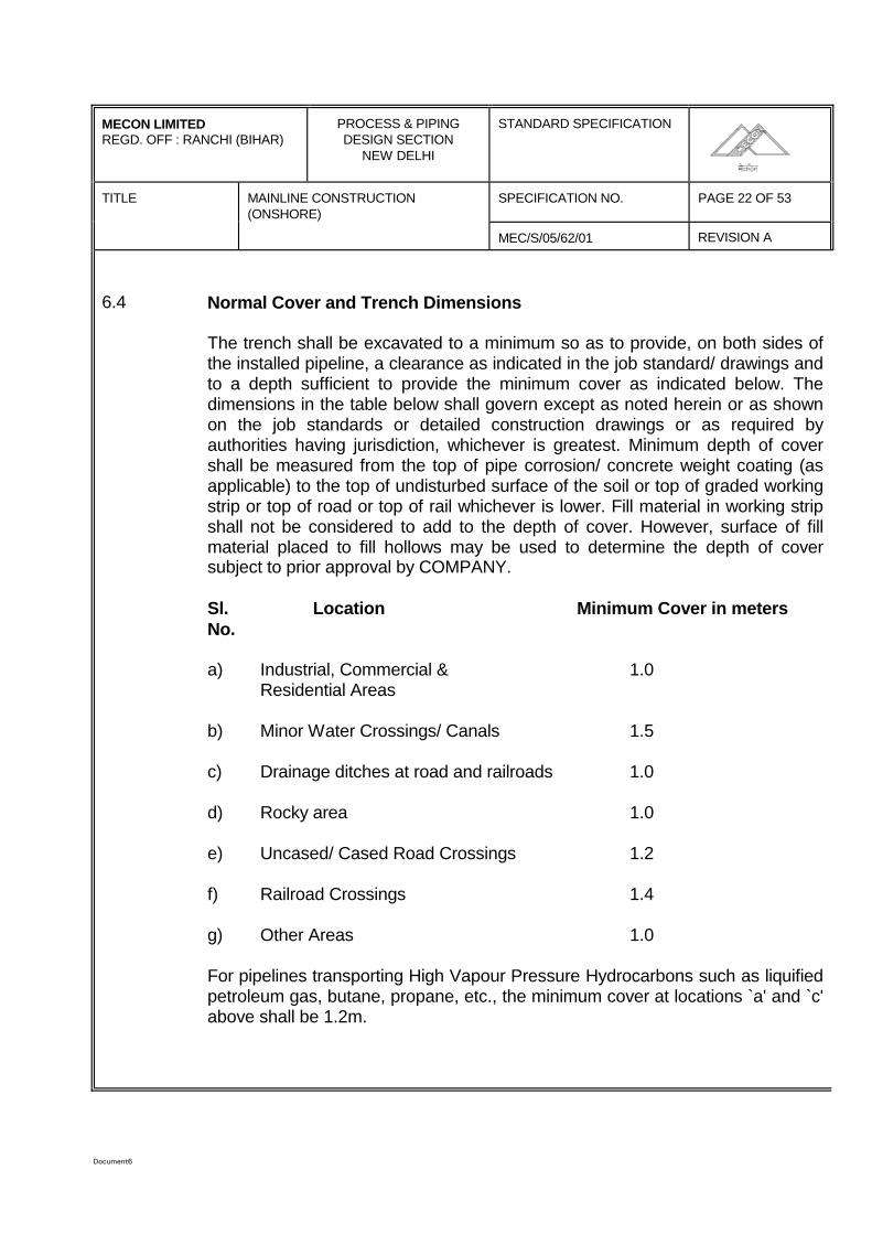
6.4 Normal Cover and Trench Dimensions
The trench shall be excavated to a minimum so as to provide, on both sides ofthe installed pipeline, a clearance as indicated in the job standard/ drawings andto a depth sufficient to provide the minimum cover as indicated below. Thedimensions in the table below shall govern except as noted herein or as shownon the job standards or detailed construction drawings or as required byauthorities having jurisdiction, whichever is greatest. Minimum depth of covershall be measured from the top of pipe corrosion/ concrete weight coating (asapplicable) to the top of undisturbed surface of the soil or top of graded workingstrip or top of road or top of rail whichever is lower. Fill material in working stripshall not be considered to add to the depth of cover. However, surface of fillmaterial placed to fill hollows may be used to determine the depth of coversubject to prior approval by COMPANY.
Sl. Location Minimum Cover in metersNo.
a) Industrial, Commercial & 1.0Residential Areas
b) Minor Water Crossings/ Canals 1.5
c) Drainage ditches at road and railroads 1.0
d) Rocky area 1.0
e) Uncased/ Cased Road Crossings 1.2
f) Railroad Crossings 1.4
g) Other Areas 1.0
For pipelines transporting High Vapour Pressure Hydrocarbons such as liquifiedpetroleum gas, butane, propane, etc., the minimum cover at locations `a' and `c'above shall be 1.2m.
Document6
MECON LIMITEDREGD. OFF : RANCHI (BIHAR)
PROCESS & PIPINGDESIGN SECTION
NEW DELHI
STANDARD SPECIFICATION
TITLE MAINLINE CONSTRUCTION(ONSHORE)
SPECIFICATION NO. PAGE 23 OF 53
MEC/S/05/62/01 REVISION A
6.5 Cutting and Removal of Paving
Whenever it is permitted by Authorities and / or COMPANY to open cut a pavedroad crossing, or where the line is routed within the road pavement,CONTRACTOR shall remove the paving in accordance with the restrictions andrequirements of the authorities having jurisdiction thereof or as directed byCOMPANY. The open cut for the road crossing shall be carried out only whenthe section of pipeline to be laid is complete. After laying the pipeline, backfillingshall be immediately performed and all the area connected with the works shallbe temporarily restored.
Throughout the period of execution of such works, CONTRACTOR shall provideand use warning signs, traffic lights or lanterns, barricades, fencing, watchman,etc. as required by the local authorities having jurisdiction and/ or COMPANY.
For all roads, paths, walkway etc. which are open-cut, CONTRACTOR shallprovide temporary diversions properly constructed to allow the passage ofnormal traffic with the minimum of inconvenience and interruptions.
The paving shall be restored to its original condition after the pipeline is installed.
6.6 Extra Depth and Clearance
At points where the contour of the earth way require extra depth to fit theminimum radius of the bend as specified or to eliminate unnecessary bending ofthe pipe according to customary good pipeline practice, or where a deep trenchis required at the approaches to crossings of roadways, railroads, rivers,streams, drainage ditches, and the like, CONTRACTOR shall excavate suchadditional depth as may be necessary at no extra cost to the COMPANY.
CONTRACTOR shall excavate to additional depth where the pipelineapproaches and crosses other pipelines, sewers, drain pipes, water mains,telephone, conduits, and other underground structures, so that the pipeline maybe laid with at least 50 centimeters free clearance from the obstacle or asspecified in the drawings, or such greater minimum distances as may berequired by authorities having jurisdiction.
Document6
MECON LIMITEDREGD. OFF : RANCHI (BIHAR)
PROCESS & PIPINGDESIGN SECTION
NEW DELHI
STANDARD SPECIFICATION
TITLE MAINLINE CONSTRUCTION(ONSHORE)
SPECIFICATION NO. PAGE 24 OF 53
MEC/S/05/62/01 REVISION A
Where the pipeline crosses areas, whose easements specifically require greaterthan normal depths of cover, the trench shall be excavated to extra depth inaccordance with the Right-of-way Agreements or as required.
CONTRACTOR shall excavate all such additional depths as may be necessaryat no extra cost to the COMPANY.
6.7 Grades, Bends and Finish of Trench
The trench is to be cut to a grade that will provide a firm, uniform and continuoussupport for the pipe. Bends shall be made in the pipe at significant changes ingrade of the trench. COMPANY reserves the right to set the grade of the trenchand locate the bends if so desired, in which case CONTRACTOR shallexcavate, at no extra cost, the trench and bend the pipe to such a grade.COMPANY desires to reduce to a minimum the required number of cold fieldbends to lay the pipe to conform to the general contour of the ground andmaintain a normal cover. This can be accomplished by cutting the trench slightlydeeper at the crest of ridges and by gradually deepening the trench inaproaches to crossings. Such trenching work shall be done by CONTRACTORat no extra cost to the COMPANY.
COMPANY intends that there will be a minmum of hand grading of the trenchbottom. However, to achieve this, CONTRACTOR will have to dig as square abottom of the trench as possible with his equipment. This in part can beobtained by adjusting and adopting the crumbling shoe and digging teeth of thetrenching machines and by use of a drag behind the trenching machines ormanually dressing-up the same. CONTRACTOR shall do such hand work in thetrench as is necessary to free the bottom of the trench from loose rock and hardclods and to trim protruding roots from the bottom and side walls of the trench.
6.8 Padding
In all cases where rock or gravel or hard soil is encountered in the bottom of thetrench, COMPANY will decide the exact extent of trench padding, that will berequired. The thickness of the compacted padding shall not be less than150mm. In those areas that are to be padded, the trench shall be at least150mm deeper than otherwise required, and evenly and sufficiently padded tokeep the pipe, when in place, at least 150mm above bottom of excavated trench.
Document6
MECON LIMITEDREGD. OFF : RANCHI (BIHAR)
PROCESS & PIPINGDESIGN SECTION
NEW DELHI
STANDARD SPECIFICATION
TITLE MAINLINE CONSTRUCTION(ONSHORE)
SPECIFICATION NO. PAGE 25 OF 53
MEC/S/05/62/01 REVISION A
Acceptable padding shall be placed under the pipeline before its installation, andaround after installation to establish at both sides and on top of the pipe apermanent layer of padding. The thickness of compacted padding on top of pipecorrosion coating shall be at least 150mm. Padding materials that are approvedby COMPANY shall be graded soil/ sand and/ or other materials containing nogravel, rock, or lumps of hard soil. Sand used for padding shall pass throughsieve size ASTM-10 or ISO-2.00.
When specified in the CONTRACT, rock shield may be used in place of or inaddition to sand padding as indicated above. Such rock shield shall be inaccordance with the specification issued for the purpose and shall be subject toCOMPANY approval.
6.9 Protection of Trench
CONTRACTOR shall keep the trench in good condition until the pipe is laid, andno claim is to be made to the COMPANY by reason of its caving either before orafter pipe is laid.
All lumber, sheet-piling jacks or other materials, that may be necessary to shorethe trench, in order to prevent caving are to be furnished and removed byCONTRACTOR.
CONTRACTOR shall dewater if necessary, using well point system or othersuitable systems, shore, or do what else might be required to excavate thetrench, install the pipe in it and backfill the trench in accordance with thesespecifications at no extra cost to COMPANY.
6.10 Protection of Underground Utilities and Special Methods
Details of some underground utilities, as far as acquired by COMPANY, shall beindicated in the Drawings. However, CONTRACTOR shall obtain plans and fulldetails of all existing and planned underground services from the relevant LocalAuthorities and shall follow these plans closely at all times during theperformance of work. CONTRACTOR shall be responsible for location andprotection of all underground lines and structures. In special locations the use oftrenching machine, backhoe may result in damage to property and subsurfacestructures likely to be encountered during excavation. At such places,CONTRACTOR shall excavate the trench manually to same specification at noextra cost.
Document6
MECON LIMITEDREGD. OFF : RANCHI (BIHAR)
PROCESS & PIPINGDESIGN SECTION
NEW DELHI
STANDARD SPECIFICATION
TITLE MAINLINE CONSTRUCTION(ONSHORE)
SPECIFICATION NO. PAGE 26 OF 53
MEC/S/05/62/01 REVISION A
Where the pipeline crosses other underground utilities/ structures, theCONTRACTOR shall first manually excavate to a depth and in such a mannerthat the utilities/ structures are located.
Temporary under pinning or any other type of supports and other protectivedevices necessary to keep the interfering structure intact shall be provided bythe CONTRACTOR at his own cost and shall be of such design as to ensureagainst their possible failure.
Despite all precautions, should any damage to any structure/ utility etc., occur,the Owner/ Authority concerned shall be contacted by the CONTRACTOR andrepair shall forthwith be carried out by the CONTRACTOR at his expense underthe direction and to the satisfaction of COMPANY and the concerned Owner/Authority. If CONTRACTOR fails to repair in reasonable time, COMPANYreserves the right to have the repair executed at the cost of the CONTRACTOR.
6.11 Encroachments and Working near other utilities
In locations, where pipeline has to be laid in the body of a road, canal, dyke orother locations under jurisdiction of Government/ Public Bodies, theCONTRACTOR shall perform such work without extra compensation, accordingto the requirement of concerned Authorities. When it becomes necessary thatCONTRACTOR has to resort to hand digging, well point, erection of sheet pilingor any other special construction methods in these areas, no extracompensation shall be paid. CONTRACTOR shall contact the Authoritiesconcerned in order to become familiar with their requirements.
In locations, where the pipeline has to be laid more or less parallel to an existingpipeline, cable and/ or other utilities in the Right-of-way, CONTRACTOR shallperform the work to the satisfaction of the Owner/ Authority of the existingpipeline/ cable/ utility. In such locations CONTRACTOR shall perform work insuch a way that even under the worst weather and flooding conditions, theexisting pipeline/ utilities remain stable and shall neither become underminednor have the tendency to slide towards the trench.
CONTRACTOR shall be liable for any damage occuring to, or resulting fromdamage to other pipelines, underground structure/ utilities, as laid down inclause 6.10 of this specification.
Document6
MECON LIMITEDREGD. OFF : RANCHI (BIHAR)
PROCESS & PIPINGDESIGN SECTION
NEW DELHI
STANDARD SPECIFICATION
SPECIFICATION NO. PAGE 27 OF 53TITLE MAINLINE CONSTRUCTION(ONSHORE)
MEC/S/05/62/01 REVISION A
6.12 Provisions for negative buoyancy to the pipe
CONTRACTOR shall check if up-floating danger is present in open trench andthen shall take appropriate measures to prevent up-floating such as applying soildams and dewatering of trench or temporary filling of water into the line (inexceptional cases).
In the case of water on the ditch bottom when the pipeline is being laid, the ditchshall be drained to the extent and for the time required to make a visualinspection of the ditch bottom. After this inspection, the presence of water will beallowed provided its level does not cause sliding of the ditch sides and pipefloating before backfilling when no concrete weighting is provided.
The water pumped out of the ditch shall be discharged into a natural watercourse.
Wherever up-floating of the pipeline after backfilling is to be reckoned with, anti-buoyancy measures shall be provided by CONTRACTOR for areas indicated inthe drawings or as may be encountered during construction, using one or acombination of the following methods :
weighting by applying a continuous concrete coating around the pipe;
weighting by installing saddle weights;
installing metal anchors screwed into the suboil in pairs;
deeper burial of pipeline;
provision of select backfill material.
The above provisions shall be in accordance with the relevant specificationsand/ or job standards/ drawings.
7.0 BENDING
CONTRACTOR shall preferably provide for changes of vertical and horizontalalignment by making elastic bends. CONTRACTOR may provide cold fieldbends, at its option for change of direction and change of slope. COMPANY atits option, may authorise fabricated bends for installation at points where inCOMPANY's judgement the use of such bends is unavoidable.
Document6
MECON LIMITEDREGD. OFF : RANCHI (BIHAR)
PROCESS & PIPINGDESIGN SECTION
NEW DELHI
STANDARD SPECIFICATION
SPECIFICATION NO. PAGE 28 OF 53TITLE MAINLINE CONSTRUCTION(ONSHORE)
MEC/S/05/62/01 REVISION A Overbends shall be made in such a manner that the center of the bend clearsthe high points of the trench bottom. Sag bends shall fit the bottom of the trenchand side bends shall conform and leave specified clearance to the outside wallof the trench.
7.1 Elastic Bends
The minimum allowable radius for elastic bends in the buried pipeline includingthat for continuous concrete weight coated pipe shall be in accordance withrelevant job standards. The elastic bend shall be continuously supported over itsfull length. A radius smaller than permitted in elastic bending shall require a coldbend.
7.2 Cold Field Bends7.2.1 The radius of cold field bends shall not be less than 40 times the pipe nominal
diameter for pipe diameter 18 inch and above and shall not be less than 30times the pipe nominal diameter for pipe diameter less than 18 inch.
7.2.2 CONTRACTOR shall use a bending machine and mandrel and employrecognized and accepted methods of bending of coated pipe in accordance withgood pipeline construction practice. However, bending machines shall becapable of making bends without wrinkles, buckles, stretching and with minimumdamage to the coating.
7.2.3 CONTRACTOR shall, before the start of the work, submit and demonstrate toCOMPANY a bending procedure which shall conform with the recommendationsof the manufacturer of the bending machine. The procedure shall includeamongst other steps - lengths, maximum degree per pull and method andaccuracy of measurement during pulling of the bend. This procedure and theequipment used shall be subject to COMPANY's approval.
7.2.4 Pipes with longitudinal welds shall be bent in such a way that the weld lies in theplane passing through the neutral axis of the bend which shall be installedpositioning the longitudinal weld in the upper quadrants. If horizontal deviationsare to be achieved by joining more adjacent bends, the bending of the pipelengths shall be made by positioning the longitudinal welds alternatively 70mmabove and below the plane passing through the neutral axis in such a way thatthe bends are welded with the longitudinal welds displaced by about 150mm andsituated in the upper quadrants. In case of vertical bends formed from a numberof pipe lengths, the longitudinal welds shall be positioned on the plane passingthrough the neutral axis of the bend to the right and left alternatively.
Document6
MECON LIMITEDREGD. OFF : RANCHI (BIHAR)
PROCESS & PIPINGDESIGN SECTION
NEW DELHI
STANDARD SPECIFICATION
TITLE MAINLINE CONSTRUCTION(ONSHORE)
SPECIFICATION NO. PAGE 29 OF 53
MEC/S/05/62/01 REVISION A
7.2.5 The pads, dies and rolls of the bending equipment shall have relatively softsurfaces to avoid damage to the pipe coating. Where applicable, fully retainingbending shoes shall be used. Roller type bending machines are preferred.
7.2.6 The ends of each bent length shall be straight and not involved anyway in thebending. The length of the straight section shall permit easy joining. In no eventshall the end of the bend be closer than 1.5m from the end of a pipe or withinone meter of a girth weld.
7.2.7 The ovalisation caused on each pipe by bending shall be less than 2.5% of thenominal diameter at any point. Ovalisation is defined as the reduction orincrease in the internal diameter of the pipe compared with the nominal internaldiameter. A check shall be performed on all bends in the presence ofCOMPANY by passing a gauge consisting of two discs with a diameter equal to95% of the nominal internal diameter of the pipe connected rigidly together at adistance equal to 300mm.
7.2.8 Cold bent pipes on site shall have the corrosion coating carefully checked withthe aid of a holiday detector for cracks in the coating down to the pipe wall. Itmust also be checked whether the coating has disbonded from the pipe wallduring bending by beating with a wooden mallet along the outer radius. Anydefects or disbonding of the coating caused during bending (also forced ridgesin the coating) shall be repaired at the CONTRACTOR's expense in accordancewith COMPANY approved procedures.
7.2.9 When pipelines are laid in parallel, the horizontal bends shall be concentric.
7.3 Miter and Unsatisfactory Bends
All bends showing buckling, wrinkles, cracks or other visible defects or which arein any way in disagreement, in whole or in part, with this specification shall berejected.
No miter bends shall be permitted in the construction of the pipe line.CONTRACTOR shall cut out and remove any bend or bends which do not meetthe specifications and shall replace the same with satisfactory bends at noadditional cost to the COMPANY. In the event the CONTRACT provides forsupply of line pipe by COMPANY, the pipes required for replacement will befurnished by COMPANY, but the cost of replacement of such pipes shall beborne by CONTRACTOR.
Document6
MECON LIMITEDREGD. OFF : RANCHI (BIHAR)
PROCESS & PIPINGDESIGN SECTION
NEW DELHI
STANDARD SPECIFICATION
SPECIFICATION NO. PAGE 30 OF 53TITLE MAINLINE CONSTRUCTION(ONSHORE)
MEC/S/05/62/01 REVISION A Cutting of factory made bends and cold field bends for any purpose are notpermitted.
8.0 LINING UP
Each length of pipe shall be thoroughly examined internally and externally tomake sure that it is free from visual defects, damage, severe corrosion (seawater pitting), dirt, animals or any other foreign objects. Each length of the pipeshall be adequately swabbed, either by use of canvas belt disc of properdiameter or by other methods approved by the COMPANY. Damaged/corrodedpipes shall be kept separate. Each length of pipe shall be pulled through justbefore being welded.
8.1 Pipe Defects and Repairs
It is CONTRACTOR's responsibility to repair all internal and/or external defects.
8.1.1 Acceptability of defects in the pipe detected during inspection at the work siteshall be determined in accordance with latest edition of COMPANY's ownmaterial specification or CODE ANSI B31.8/B 31.4 whichever is more stringent.
8.1.2 The maximum permissible depth of dents in pipes upto and including 123/4" ODis 5mm and for pipes over 12 3/4" OD is 2% of the nominal pipe diameter.
8.1.3 Dents which contain a stress concentrator such as scratch, gauge, arc burn orgroove, and dents located at the longitudinal, spiral or circumferential weld shallbe removed by cutting out the damaged portion of pipe as a cylinder.
8.1.4 Repair on line pipe shall be executed as specified in COMPANY's materialspecification or Code ANSI B 31.8/B 31.4, whichever is more stringent. A recordof all repairs is to be maintained by CONTRACTOR. This record, provided withthe pipe identification number is to be submitted to the COMPANY.
8.1.5 If due to cutting or repairs, the pipe identification number is removed, it shall bereprinted immediately by CONTRACTOR in the presence of COMPANY. In theevent, the CONTRACT provides for supply of line pipe by COMPANY,CONTRACTOR shall be charged for any pipe length due to loss of identificationnumber. No pipe without identification number shall be transported and/orwelded into the pipeline.
Document6
MECON LIMITEDREGD. OFF : RANCHI (BIHAR)
PROCESS & PIPINGDESIGN SECTION
NEW DELHI
STANDARD SPECIFICATION
TITLE MAINLINE CONSTRUCTION(ONSHORE)
SPECIFICATION NO. PAGE 31 OF53
MEC/S/05/62/01 REVISION A
8.1.6 Repair of damaged pipe ends by hammering and/or heating is not allowed. If thedented area is minor and at least 200mm away from the pipe end, and the steelis not stretched, severed, or split in the COMPANY's opinion, the pipe may bestraightened with a proper jack.
8.2 Pipe Handling And Skid Spacing
8.2.1 When lifting pipe, care must be taken not to kink or overstress it. Proper pipeslings approved by COMPANY shall be used. CONTRACTOR shall submit hismethod of skidding and skid spacing for COMPANY's approval. A strip of softmaterial shall be placed in between skid and pipe to protect the external coatingof the pipe. The material shall be approved by the COMPANY.
8.2.2 The maximum skid spacing is not allowed before the stringer bead and the topand bottom reinforcements are completed, provided that the distance betweenthe incomplete weld and the skid shall not exceed 9 (nine) percent of the skidspacing.
8.2.3 Skids shall be atleast 1.20 meter long. For pipe with an O.D. of 12-3/4 inch andlarger the skids in contact with the pipe shall have a width of at least 200mm.For pipe with an O.D. of less than 12 inch the skids in contact with the pipe shallhave a width of atleast 150mm. Pipe supports shall be stable, so that pipemovement will not cause the supports to move. Skids shall not be removedunder a string before lowering in. The welded pipe shall be maintained on skidsat the minimum distance of 500mm above ground. Crotches shall be installed atfrequent intervals (atleast every 10th support) with a greater number required atbends and undulation grounds.
8.3 Night Caps
At the end of each day's work or every time when joining and welding operationsare interrupted, the open ends on the welded strings of pipes shall be cappedwith a securely closed metal cap or plug as approved by COMPANY so as toprevent the entry of dirt, water, or any foreign matter into the pipeline. Thesecovers shall not be removed until the work is to be resumed. The caps/plugsused shall be mechanical type and shall not be attached to pipe by welding orby any other means which may dent, scratch or scar the pipe.
Document6
MECON LIMITEDREGD. OFF : RANCHI (BIHAR)
PROCESS & PIPINGDESIGN SECTION
NEW DELHI
STANDARD SPECIFICATION
SPECIFICATION NO. PAGE 32 OF 53TITLE MAINLINE CONSTRUCTION(ONSHORE)
MEC/S/05/62/01 REVISION A 8.4 Temporary Caps
Whenever the welded strings of pipes are left open at intervals to be tied in laterafter an appreciable time lag, under roads, railroads, rivers, marshy crossings,ets., temporary caps approved by COMPANY shall be welded to the ends of thepipe.
9.0 LAYING OF PIPE
9.1 Lowering In Trench
9.1.1 Lowering can start after removal from ditch bottom of all off cuts, pipe supports,stones, roots, debris, stakes, rock projections below underside of pipe and anyother rigid materials which could lead to perforation or tearing of the coating.Sand padding and / or rock shield shall be provided as required in accordancewith clause 6.8 of this specification.
9.1.2 Lowering shall follow as soon as possible, after the completion of the jointcoating of the pipeline. In the case of parallel pipelines, laying shall be carriedout by means of successive operations, if possible without interruption.
9.1.3 Before lowering in, a complete check by a full circle holiday detector for pipecoating and for field joint coating shall be carried out and all damages repairedat CONTRACTOR's cost. All points on the pipeline where the coating has beenin contact with either the skids or with the lifting equipment during laying, shall becarefully repaired. If, after checking, it becomes necessary to place the pipelineagain on supports at the bottom of the trench, these must be padded in such away as to prevent damage to the coating, thus avoiding necessity for furtherrepairs when the pipe is finally raised and laid. Before the last operation, a checkmust be made of the coating at points of contact with the supports.
9.1.4 Before lowering in, short completed sections of the pipeline shall be cleanedwith compressed air in order to remove all dirt, etc. from the inside of pipesections.
9.1.5 The pipeline shall be lifted and laid using, for all movements necessary, suitableequipment of non-abrasive material having adequate width for the fragility of thecoating. Care shall be exercised while removing the slings from around thecoated pipe after it has been lowered into the trench. Any damage caused to thecoating shall be promptly repaired. Lowering in utilizing standard pipe cradlesshall be permitted if CONTRACTOR demonstrates that pipe coating is notdamaged. No sling shall be put around field joint coating.
Document6
MECON LIMITEDREGD. OFF : RANCHI (BIHAR)
PROCESS & PIPINGDESIGN SECTION
NEW DELHI
STANDARD SPECIFICATION
TITLE MAINLINE CONSTRUCTION(ONSHORE)
SPECIFICATION NO. PAGE 33 OF 53
MEC/S/05/62/01 REVISION A
9.1.6 Wherever the pipeline is laid under tension, as a result of an assembly error (forexample, incorrect positioning of bends, either horizontal or vertical), the trenchshall be rectified or in exceptional cases a new assembly shall be carried out, tobe approved by COMPANY, so that it fits the excavation and the laying bed.
9.1.7 Laying shall be carried out under safe conditions so as to avoid stresses andtemporary deformations of the equipments which may cause damage to thepipeline itself and to the coating. In localised points where the right-of-way isrestricted to the minimum necessary for the transit of mechanical equipment, thelaying shall be carried out using other suitable means. The pipe shall be placedon the floor or the excavation, without jerking, falling, impact or other similarstresses. In particular, care must be taken that the deformation caused duringthe raising of the pipe work from the supports, does not exceed the values forthe minimum allowable radius of elastic curvature, so as to keep the stresses onthe steel and on the coating within safe limits. The portion of the pipelinebetween trench and bank shall be supported by as many side-booms asrequired and approved by COMPANY for holding the line in gentle S-curvemaintaining minimum elastic bend radius as specified in job standard. Loweringin and back-filling shall preferably be carried out at the highest ambienttemperature.
9.1.8 The pipeline must be laid without interruption for the whole or the length ofsection available. Where water is present, no laying shall be permitted until theditch has been drained to the extent and for the time necessary to make visualinspection possible of the bed on which the pipe is to be laid. Following suchinspections, the presence of water will be permitted, provided that it is not sohigh as to cause cave-in of the walls of the trench or floating of the pipelinebefore backfilling, when weighting is not provided for the pipe.
9.1.9 CONTRACTOR shall take precautions immediately after lowering in to preventthe movement of the pipe in trench.
9.1.10 In laying parallel pipelines in the same trench, the minimum distances betweenthe pipeline indicated in the approved drawings shall be observed. Once the firstpipeline has been positioned, it shall in no way be disturbed by laying of thesubsequent pipeline.

Document6
MECON LIMITEDREGD. OFF : RANCHI (BIHAR)
PROCESS & PIPINGDESIGN SECTION
NEW DELHI
STANDARD SPECIFICATION
TITLE MAINLINE CONSTRUCTION(ONSHORE)
SPECIFICATION NO. PAGE 34 OF 53
MEC/S/05/62/01 REVISION A
At every seven meters along the trench sand/earth filled bags shall be placedbetween the parallel pipelines so as to ensure maintenance of the minimumstipulated distance between the parallel lines.
9.2 Overhead Sections and Sections in Tunnel
9.2.1 The following works shall be completed before proceeding with the assemblyand laying of overhead pipelines :
- Construction of the pipe support structures or of mounts on supports.
- Paints and/or coating of the pipework, as indicated in the engineeringspecification.
9.2.2 The erection of the supports shall be carried out taking care that the elevationand alignment is in accordance with the drawings.
In the case of metal work supports, prefabrication and/or assembly shall takeinto account the maximum allowed free span and the supports shall not interferewith the pipeline welds.
9.2.3 In case roller supports are used, the roller shall be lubricated, then checked forsmooth rotation and, in case of seizure, the defect shall be repaired or rollershall be replaced. In the case of overhead section where the pipeline is slanting,the alignment of the end supports shall be made after placing the pipeline inposition. Before installation of the pipe section, all the rollers shall be perfectlycentered acting on the seat of the support plates.
The above alignment operations shall be carried out before connecting theoverhead section with the ends of the buried section.
9.2.4 Lifting, moving and laying of the pipeline shall be carried out in accordance withthe provisions of clause 9.1.5.
An insulation sheet shall be installed to isolate the pipe from the support orsupport from the earth.
The sheet shall be hard polyethylene at least 5mm thick.
It shall extend at least to 1cm outside the saddles or clamps.
Document6
MECON LIMITEDREGD. OFF : RANCHI (BIHAR)
PROCESS & PIPINGDESIGN SECTION
NEW DELHI
STANDARD SPECIFICATION
SPECIFICATION NO. PAGE 35 OF 53TITLE MAINLINE CONSTRUCTION(ONSHORE)
MEC/S/05/62/01 REVISION A 9.2.5 Moving supports, if any, shall be centered on their support and allow for a
movement of at least 300mm in both directions.
9.2.6 A comprehensive report/method statement on the laying operation to be usedshall be submitted to the COMPANY well in advance for approval. The report asa minimum shall include, but not limited to the following:
(a) Method of installation by lifting (as a preferred method).
(b) Pulling method and related calculations, whenever lifting method cannotbe used.
(c) Pulling device and its characteristics
(d) Method of anchoring the pulling device
(e) Characteristics of the pulling rope
(f) Braking device, if any
(g) Pipeline assembly systems.
10.0 BACK-FILLING
10.1 Backfilling shall not be done until the pipe and appurtenances have the proper fitand the pipe is following the ditch profile at the required depth that will providethe required cover and has a bed which is free of extraneous material and whichallows the pipe to rest smoothly and evenly. Before any such work is done, itshall be the CONTRACTOR's responsibility to first secure the approval ofCOMPANY. If any backfilling is done without COMPANY's approval, COMPANYwill have the right to require removal of the backfill for examination, and the costof such uncovering and refilling shall be borne by CONTRACTOR. Backfilling oftrench in water courses shall be carried out as per the relevant specificationsissued for the purpose.
10.2 Backfilling shall be carried out immediately after the pipeline has been laid in thetrench, inspected and approved by the COMPANY, so as to provide a naturalanchorage for the pipeline, thus avoiding long exposure of coating to hightemperature, damaging actions of adverse weather conditions, sliding down of trench sides and pipe movement in the trench. If immediate back filling isnot possible, a covering of atleast 200mm of earth, free of rock and hard lumpsshall be placed over and around the pipe and coating.
Document6
MECON LIMITEDREGD. OFF : RANCHI (BIHAR)
PROCESS & PIPINGDESIGN SECTION
NEW DELHI
STANDARD SPECIFICATION
TITLE MAINLINE CONSTRUCTION(ONSHORE)
SPECIFICATION NO. PAGE 36 OF 53
MEC/S/05/62/01 REVISION A
On no account the top soil from the ROW be used for this purpose. In general,the trench shall be dry during backfilling. Deviations there of must have priorapproval of the COMPANY. The backfill material shall contain no extraneousmaterial and/or hard lumps of soil which could damage the pipe / coating orleave voids in the backfilled trench. After the initial backfill has been placed intothe trench to a level slightly above the surrounding ground, CONTRACTOR shallcompact the backfill material. The surplus material shall be neatly crowneddirectly over the trench and the adjacent excavated areas on both sides of thetrench as per clause 6.2.1, to such a height which will, in COMPANY's opinion,provide adequately for future settlement of the trench backfill during themaintenance period and thereafter. The crown shall be high enough to preventthe formation of a depression in the soil when backfill has settled into its permanent position. Should depression occur after backfill, CONTRACTORshall be responsible for remedial work at no extra cost to COMPANY. Surplusmaterial, including rock, left from this operation shall be disposed of to thesatisfaction of land owner or authority having jurisdiction at no extra cost to theCOMPANY.
For further requirements reference is made to Section of 14.0 "Clean-up andRestoration of Right-of-Way" of this specification.
10.3 Rock, gravel, lumps of hard soil or like materials shall not be backfilled directlyonto the pipe unless 'padding' and/or rock shell has been provided as perSection 6.0 of this specification. When "Padding" as described in Section 6.0 ofthis specification is to be used, the following shall be applicable.
Where rock, gravel, lumps of hard soil or like materials are encountered at thetime of trench excavation, sufficient earth, sand or select backfill materials shallbe placed around and over the pipe to form a protective cushion extending atleast to a height of 150mm above the top of the pipe. Select backfill materials forpadding that are acceptable to COMPANY shall be soil, sand, clay or othermaterial containing no gravel, rock or lumps or hard soil. Whether such paddingmaterial would be taken from the adjacent spoil bank or imported fromelsewhere shall be directed by COMPANY. All these works shall be carried outby CONTRACTOR at no extra cost to COMPANY. Loose rock may be returnedto the trench after the required selected backfill material has been placed,provided the rock placed in the ditch will not interfere with the use of the land bylandowner, or tenant.
Document6
MECON LIMITEDREGD. OFF : RANCHI (BIHAR)
PROCESS & PIPINGDESIGN SECTION
NEW DELHI
STANDARD SPECIFICATION
TITLE MAINLINE CONSTRUCTION(ONSHORE)
SPECIFICATION NO. PAGE 37 OF 53
MEC/S/05/62/01 REVISION A
10.4 When the trench has been dug through drive ways or roads, all backfills shall beexecuted with sand or a suitable material as approved by COMPANY and shallbe thoroughly compacted. In certain cases, special compaction methods, suchas moistening or ramming of the backfill in layers may be required byCOMPANY. COMPANY and any public or private authority having jurisdictionover a road, street or drive way may require that the surface of the backfill begraveled with crushed rock or some other purchased material and the road shallbe repaved. In such instances, CONTRACTOR shall comply with saidrequirements at no extra cost to COMPANY.
10.5 Trenches excavated in dykes which are the property of railways or which arepart of main roads shall be graded and backfilled in their original profile andcondition. If necessary, new and/or special backfill materials shall be suppliedand worked-up. The materials required may include gravel, special stabilizationmaterials or stabilized mixtures. However, special processing and/or compactingmethods shall require the approval of COMPANY and/or competent authorities.
10.6 The trench in irrigated and paddy fields shall be backfilled to within 300mm ofthe top, then rammed and further backfilled until the trench is completelybackfilled. Surplus material remaining after the operation shall be spread overthe ROW as specified in Section 14.0 "Clean-up and Restoration of Right-of-Way", of this specification.
10.7 At the end of each day's work, backfilling shall not be more than 500 metersbehind the head end of lowered-in pipe, which has been padded and approvedfor backfill. The backfill shall be maintained by CONTRACTOR againstwashouts etc., until the completion and final acceptance of the work byCOMPANY.
10.8 CONTRACTOR shall furnish materials and install breakers in the trench in steepareas (slope generally 10% and more) for the purpose of preventing erosion ofthe backfill. The type of breakers installed shall be as per the approveddrawings. Breakers shall be constructed of grout bags filled with a mixture of 4:1Sand:Portland cement at COMPANY's direction. CONTRACTOR may proposeother methods such as foam dams etc. which shall be subject to approval byCOMPANY. Such works shall be at no extra cost to COMPANY.CONTRACTOR shall pay attention to the direction of backfilling in such steepareas.
Document6
MECON LIMITEDREGD. OFF : RANCHI (BIHAR)
PROCESS & PIPINGDESIGN SECTION
NEW DELHI
STANDARD SPECIFICATION
TITLE MAINLINE CONSTRUCTION(ONSHORE)
SPECIFICATION NO. PAGE 38 OF 53
MEC/S/05/62/01 REVISION A
10.9 When backfilling the trenches in sloping terrains or steep areas, where in theopinion of the COMPANY, the backfill may be washed out of the trench, sheetpiling or other effective water breakers across the trench shall be provided byCONTRACTOR. This is to divert the flow of water away from the trench intonormal drainage followed before laying the line. In no case, the water is to bedrained via the trench or via channels other than those followed before the linewas laid.
10.10 CONTRACTOR shall leave the pipe uncovered at certain locations to allowCOMPANY to survey the center line of the pipe and the level of the pipeline inthe backfilled trench. Within 48 hours after backfilling, COMPANY shall havecarried out such survey and informed CONTRACTOR of any realigning, ifrequired. Thereafter CONTRACTOR shall compact the backfill.
The maximum allowable deviation from the centerline for land sections asstaked out by COMPANY and as referenced by CONTRACTOR after backfillingis limited to:
Pipeline dia upto and including 24" : 200mm
Pipeline greater than 24" : 300mm
10.11 Before backfilling of the trench, CONTRACTOR shall comply with therequirements of Clause 6.12 of this specification.
10.12 Stabilization of backfill shall be carried out by the CONTRACTOR in sandyareas and other such places to obtain consolidated cover as directed by theCOMPANY. CONTRACTOR shall carry out the stabilization over the pipeline atno extra cost to COMPANY.
The backfill shall be stabilized preferably with 150mm layer of marl, mattressesof gatch other than straw or other stable materials. The width of stablisation shallbe atleast 5.0 meters on either side of the pipeline, plus one meter for every 10meters height of dune (where the line passes through the dune areas).
10.13 Temporary workers shall be installed during backfilling and the survey as perclauses 10.10 to locate the pipeline axis. These markers shall then be replacedwith permanent pipeline markers.
Document6
MECON LIMITEDREGD. OFF : RANCHI (BIHAR)
PROCESS & PIPINGDESIGN SECTION
NEW DELHI
STANDARD SPECIFICATION
TITLE MAINLINE CONSTRUCTION(ONSHORE)
SPECIFICATION NO. PAGE 39 OF 53
MEC/S/05/62/01 REVISION A
10.14 Backfilling shall be preferably carried out at the highest ambient temperature.
11.0 TIEING-IN
11.1 The unconnected sections of the pipe line at various locations have to be tied inafter the sections are coated, lowered and backfilled. The sections to beconnected shall have at the ends, sections of over lapping, uncovered pipe ofsufficient length to absorb, without inducing excessive stresses in the steel,small displacements necessary for perfect alignment and connection of theends.
11.2 Tie-in shall preferably be carried out at ambient temperatures corresponding tothe average operating temperature in the case of a pipeline conveying fluids atnormal temperatures and at the maximum ambient temperature in the casewhere the pipeline is carrying fluids at high temperature.
11.3 CONTRACTOR shall carry out tie-in-welding (including necessary cutting,bevelling, grinding of pipe weld seams and line-up etc.) cleaning, priming,coating and backfilling for the tie-in portion as per relevant specifications.CONTRACTOR shall also excavate the required bell-holes for the connection.Bell-holes made to facilitate welding shall provide adequate clearance to enablethe welders to exercise normal welding ability and skill. All tie-in welds shall beradiographically examined.
11.4 The tie-in should be done in such a way as to leave a minimum of strain in thepipe. If necessary, with respect to the trench, realigning of the pipe shall be doneto eliminate force or strain in the pipe by the CONTRACTOR at no extra cost toCOMPANY.
11.5 If a pup end cannot be avoided for tie-in, the minimum length that shall beadded is 1.0 meters and two or more such pups shall not be welded together. Allcut-off lengths greater than 1.0 meters shall be moved ahead in order to bewelded into the pipeline at a suitable location. Tie-in with two or more pups maybe used provided that they each have minimum length of 1.0 meter and areseparated by an entire length of pipe. In no case more than three (3) welds shallbe permitted on a 10 meter length of pipeline.
Document6
MECON LIMITEDREGD. OFF : RANCHI (BIHAR)
PROCESS & PIPINGDESIGN SECTION
NEW DELHI
STANDARD SPECIFICATION
TITLE MAINLINE CONSTRUCTION(ONSHORE)
SPECIFICATION NO. PAGE 40 OF 53
MEC/S/05/62/01 REVISION A
11.6 In connecting pipes, special items, fittings and equipment where different wallthickness are to be welded, CONTRACTOR shall follow the proceduresindicated in ANSI B31.8/ANSI B31.4, as applicable. The required tapering shallbe done by CONTRACTOR at no extra cost to COMPANY.
11.7 For tie-in of adacent sections of pipeline already pressure tested, the pup usedfor tie-in shall be of single length or off-cuts of pipe which have already beenhydrostatically tested. CONTRACTOR shall take care that sufficient number ofpretested pipes with different wall thicknesses are readily available.
12.0 SPECIAL INSTALLATIONS ON THE PIPELINE.
12.1 General
12.1.1 In addition to constructing the pipeline, CONTRACTOR shall also install certainother auxiliary facilities and appurtenances.
CONTRACTOR shall do all work necessary at each of the installations toprovide facilities which are complete in all respects and ready for operation.
Without limiting the generality thereof, the work required to complete theinstallations shall, where applicable, include all site surveys, site preparation,filling, grading, fencing, foundations, installation of block valves, side valves,pipework, pipe supports, pressure gauges, mechanical facilities, civil work,painting, installation of all electrical equipments, motors, cables, conduIt, wiringand fixtures and hooking up of same; installation of all instruments, piping,valves and fittings; mount all instruments and make all piping and electronicconnections, etc.
On completion, all elements of each installation shall be checked our and testedfor full and correct operation in the presence of and to the satisfaction ofCOMPANY. All work shall be carried our strictly in accordance with theappropriate codes, the approved drawings, and this and other relatedspecifications.
CONTRACTOR shall fabricate all piping and install valves and fittings asrequired by the detailed engineering drawings prepared by him and approved byCOMPANY.
Document6
MECON LIMITEDREGD. OFF : RANCHI (BIHAR)
PROCESS & PIPINGDESIGN SECTION
NEW DELHI
STANDARD SPECIFICATION
SPECIFICATION NO. PAGE 41 OF 53TITLE MAINLINE CONSTRUCTION(ONSHORE)
MEC/S/05/62/01 REVISION A
Stainless steel lines will be "swaged" using permanent fittings installed with ahydraulic device.
Cold bending for the fitting of 1/2" and 1/4" pipes is allowed when specialbending tools are used with guides to prevent flattening. The minimum radiusallowed shall not be less than R = 10 D where D is the outside diameter of pipe.
The bending tool shall be subject to COMPANY's approval.
CONTRACTOR shall ensure that the piping assemblies are not in a strain priorto the final bolting or welding. CONTRACTOR shall also ensure that allequipment and piping are thoroughly swabbed clean of all dust, refuse, welding-spatter, scale, or any potentially detachable matter prior to the tie-in or finalbolting.
12.1.2 Dimensional tolerances.
These tolerances apply to in line items and corrections for other lines. Thesetolerances can be executed on items such as vents, drains, dummy supports,field supports, temperature and pressure connections, where the deviation willnot affect another spool.
a) General dimension such as face to face, face or end to end, face or endto center, and center to center : ± 3 mm.
b) Inclination of flange face from true in any direction: 4 mm per meter.
c) Displacement of branch connection from indicated location: ± 1.6mm.When multiple branches are involved, the displacement of the branchesshall not exceed 3mm from a common point.
d) Rotation of flange bolt holes shall not exceed 1.6 mm.
12.1.3 Flanged connections.
CONTRACTOR shall ensure that all flange faces are parallel and centered,according to standard practice, prior to final bolting. CONTRACTOR shall notuse bolting forces as a means for attaining alignment. A gasket of proper sizeand quality shall be installed between the flanges at each joint.
Document6
MECON LIMITEDREGD. OFF : RANCHI (BIHAR)
PROCESS & PIPINGDESIGN SECTION
NEW DELHI
STANDARD SPECIFICATION
TITLE MAINLINE CONSTRUCTION(ONSHORE)
SPECIFICATION NO. PAGE 42 OF 53
MEC/S/05/62/01 REVISION A
Bolts shall be tightened in diagonal sequence and shall be centered with equalamounts of thread visible on both sides. Bolts shall be uniformly tightened toproduce a leak-proof joint. Bolts that yield during tightening shall be remover anddiscarded. It is mandatory that a torque wrench is used for bolt tightening.
12.1.4 Threaded connections.
Damaged threads shall be cut from the end of a run and the pipe shall berethreaded.
CONTRACTOR shall properly align all threaded joints. Pipe entering unionsshall be true to centreline so the union will not be forced during tightening. Thethreaded pipe shall not project through fittings to cause interference with valvesor other operating mechanisms.
Except for the threaded connections of instruments, which will require periodictesting and maintenance, all threaded connections shall be seal welded. Thelatter joints shall be made up without pipe joint compound and with a minimumof oil from the threaded cutter. Seal welds should taper into the pipe with as littlediscontinuity as possible and should cover all threads.
12.1.5 Welded connections
Where the Ends of the piping components being welded have an internalsurface misalignment exceeding 1.6mm, the wall of the component extendinginternally shall be trimmed by machining so that the adjoining internal surfaces will be approximately flush. All welding shall be performed in accordance withthe specification " Specification for welding of pipelines and related facilities".Tie - ins between fixed points shall be made at maximum ambient temperature.
.12.1.6 Civil Work
Civil work shall be provided in accordance with Specifications issued for thepurpose.
Document6
MECON LIMITEDREGD. OFF : RANCHI (BIHAR)
PROCESS & PIPINGDESIGN SECTION
NEW DELHI
STANDARD SPECIFICATION
TITLE MAINLINE CONSTRUCTION(ONSHORE)
SPECIFICATION NO. PAGE 43 OF 53
MEC/S/05/62/01 REVISION A
12.1.7 Painting
All exposed surfaces like piping, valves, structures, and miscellaneousappurtenances shall be painted in accordance with the specifications issued forthis purpose. The corrosion coating on pipe surface will end approximately 0.3meter above the finish grade and it will be necessary for CONTRACTOR toprovide a clean interface at the junction of the protective coating and the paint.
12.1.8 Coating of buried-Installations, etc.
All buried valves, insulating joints, flowtees, bends, other in-line fittings andappurtenances shall be coated with minimum three coats of approved quality ofcoal-tar epoxy or any other equivalent suitable COMPANY approved coating atno extra cost to the COMPANY. For buried pipes either heat shrink tapesconforming to COMPANY's specification or coal tar epoxy shall be used.CONTRACTOR shall submit to COMPANY a report used alongwith all the testcertificates. Only after obtaining written approval from the COMPANY,CONTRACTOR shall commence the work of coating.
12.1.9 Clean-up
After all required tests have been concluded satisfactorily CONTRACTOR shallclean up the site as laid down in the specifications issued for the purpose. TheSite finish shall be graded in accordance with the approved drawings.
12.2 Installation of Valves and Valve Stations
12.2.1 Block and sectionalising valve stations shall be installed as shown on theapproved drawings. It is CONTRACTOR's responsibility to have the unitscompletely assembled, tested and made fully functional including all relatedinstruments etc.
12.2.2 The civil and structural work shall be carried our in accordance with the relevantspecifications issued for the purpose and in accordance with the approveddrawings as directed by COMPANY. This work as a minimum shall includeclearing, grading, fencing, foundations, etc, as required. All above groundstructures shall be painted as per the specification and color code given by theCOMPANY.
Document6
MECON LIMITEDREGD. OFF : RANCHI (BIHAR)
PROCESS & PIPINGDESIGN SECTION
NEW DELHI
STANDARD SPECIFICATION
TITLE MAINLINE CONSTRUCTION(ONSHORE)
SPECIFICATION NO. PAGE 44 OF 53
MEC/S/05/62/01 REVISION A
12.2.3 A suitable concrete foundation as directed by COMPANY shall be constructedon which the valve shall be firmly installed, after embedding an insulating sheetof hard polyethylene with a thickness of atleast 5mm or equivalent. Suchinsulating sheet is also to be installed under pipe clamps, etc.
12.2.4 Valves with flow arrows shall be installed according to the normal flow in thepipeline. During, welding, the valves shall be in fully open position. In addition allmanufacturer's instructions shall be followed.
Care shall be taken to avoid entry of sand particles etc. to valve body, seals etc.during transportation, storage, assembly and installation.
12.2.5 For valves and piping installed below ground and/or above ground, the anti-corrosion coating/painting shall be as per the requirements of the relevantspecifications issued for the purpose. The anti-corrosion coating below groundshall extend upto 300mm above grade at the lowest point.
12.2.6 Sectionalizing valves shall be installed on sections of the pipeline in thehorizontal position only or with an inclination not greater than that allowed by thevalve manufacturer. Installation shall be done in such a way that there is nostrain in the welded joint while the pipeline at upstream and downstream sidesare straight.
12.2.7 All valves shall always be handled using equipment and methods to avoidimpact, shaking and other stresses. In particular, the equipment and tools forlifting and handling shall never be done through handwheel, valve stem, jointsand other parts which may suffer damage.
12.2.8 All sectionalizing valve and any other inline assemblies shall be prefabricatedand tested hydrostatically ex-situ as per applicable specification. All suchassemblies shall be installed at the locations shown in the drawings only aftersuccessful completion of the hydrostatic test and dewatering. Thereafter theends of the assembly shall be closed off. CONTRACTOR shall carry outnecessary excavation, cutting, bevelling and welding of the tie-ins required forthe installation of such assembly. The tie-in joints shall be radiographicallyexamined over 100% length and also 100% ultrasonically examined prior tobackfilling. All works shall be executed in accordance with the relevantspecifications issued for the purpose.

Document6
MECON LIMITEDREGD. OFF : RANCHI (BIHAR)
PROCESS & PIPINGDESIGN SECTION
NEW DELHI
STANDARD SPECIFICATION
TITLE MAINLINE CONSTRUCTION(ONSHORE)
SPECIFICATION NO. PAGE 45 OF 53
MEC/S/05/62/01 REVISION A
12.3 Installation of Scraper Launchers and Receivers
12.3.1 Scraper stations shall be fabricated and installed as per the approved drawingsand whenever applicable as per the requirements of clause 12.2 of thisspecification. It is CONTRACTOR's responsibility to have the units completelyassembled, tested and made fully functional including all instruments & relatedpiping.
12.3.2 The civil and structural works for the scraper stations shall be carried out as perthe relevant specifications, in accordance with the drawings and as directed bythe COMPANY. The work as a minimum shall include site survey, sitepreparation, clearing, grading, fencing, foundations, etc. as required.
12.3.3 It shall be CONTRACTOR's responsibility to maintain elevations shown on theapproved drawings and to carry out any pipework adjustments, necessary forthis purpose. Field cuts shall be square and accurate and field welds shall notbe performed under stress of pipe ends.
12.3.4 The painting for the scraper stations shall be carried out as per "Specificationsfor Painting". The underground sections shall be coated as specified for thepipeline upto atleast 300mm above grade.
12.3.5 The hydrostatic testing of the scraper stations shall be executed after installationin accordance with the relevant specification issued for the purpose.
12.4 Installation of Insulation Joints
12.4.1.1 Insulation joints shall be installed at the locations shown in the drawings.CONTRACTOR shall obtain approval from the COMPANY before installation ofthe insulation joints.
12.4.2 Handing and installation of the insulating joints shall be carried out with allprecautions required to avoid damage and excessive stresses and that theoriginal pup length is not reduced.
12.4.2 The insulating joints and the welded joints shall be protected by external coatingas per relevant specifications issued for the purpose.
Document6
MECON LIMITEDREGD. OFF : RANCHI (BIHAR)
PROCESS & PIPINGDESIGN SECTION
NEW DELHI
STANDARD SPECIFICATION
TITLE MAINLINE CONSTRUCTION(ONSHORE)
SPECIFICATION NO. PAGE 46 OF 53
MEC/S/05/62/01 REVISION A
12.4.4 The in-line inserting shall be made on the buried pipeline; care shall be taken tooperate at an external temperature as close as possible to the pipeline operatingtemperature.
The joints shall be inserted on straight sections and laid on a fine sand bed.
12.4.5 During the execution of the in-line connection welding, the propagation of heatshall be avoided. To achieve this, the joint shall be kept cold by means of nagscontinuously wetted.
12.4.6 Insulating joints shall be electrically tested before welding into the pipeline. Theelectrical conductance test shall be carried out using a Megger. Measurement ofthe insulation resistance across the joints shall be approx. one (1) Mega Ohm.The tests shall be repeated after installation and welding of the joint into thepipeline to verify that the assembly is undamaged.
13.0 WORKING SPREAD LIMITATIONS
CONTRACTOR shall, in general, observe the following maximum distancesbetween the working mainline spread:
Between ROW grading, clearing and backfilling :40 Kms
Between backfilling and final clean-up :15 Kms
The above limitations do not apply to point spreads such as continuous rockblasting, river crossing, etc.
Any deviations from the above shall require prior approval of COMPANY.COMPANY reserves the right to stop the work, in case the approved spreadlimitations are exceeded and CONTRACTOR shall not be paid anycompensation for stoppage of work.
14.0 CLEAN-UP AND RESTORATION OF RIGHT OF WAY
14.1 CONTRACTOR shall restore the ROW and all sites used for the construction ofpipelines, water crossing and other structures in accordance with COMPANY'sinstructions, and deliver them to the satisfaction of COMPANY.
Document6
MECON LIMITEDREGD. OFF : RANCHI (BIHAR)
PROCESS & PIPINGDESIGN SECTION
NEW DELHI
STANDARD SPECIFICATION
TITLE MAINLINE CONSTRUCTION(ONSHORE)
SPECIFICATION NO. PAGE 47 OF 53
MEC/S/05/62/01 REVISION A
14.2 Surplus Materials
The following stipulations shall apply in case CONTRACT provides for supply ofline pipe, bare and/or corrosion coated, by COMPANY.
All surplus and defective materials supplied by COMPANY shall be collected byCONTRACTOR and delivered to designated stockpile areas.
All Pipe-ends shorter than 1.0m shall be returned to COMPANY being scrap, allpipes longer than 8.0m shall be reconditioned (bevels, coating, provided withpipe letter, number and length) and be returned to COMPANY's designatedstockpile areas together with all undamaged, unused COMPANY suppliedmaterials. All pieces between 1.0 and 8.0m shall be charged to theCONTRACTOR by COMPANY. CONTRACTOR shall record these returnedmaterials in the Material account, to be prepared by him.
14.3 Disposal
14.3.1 All surplus and defective materials supplied by CONTRACTOR and all trash,refuse and spoiled materials shall be collected and disposed of byCONTRACTOR.
14.3.2 The ROW shall be cleared of all rubbish, broken skids, empty cans, card board,sacks, stamps, trash, and leftover construction material. All burnable matter shallbe burned, but only after obtaining appropriate permits for such burning. Ifburning is not allowed, CONTRACTOR shall haul the clean-up material toapproved dumping area. All scrap metal and unburnable material shall bedisposed of, in an appropriate manner, but never be buried in the ROW.
14.3.3 Surplus soil can only be removed from the Owner's plot after authorisation byCOMPANY.
14.3.4 All dumping fees connected with the disposal of materials shall be to theaccount of CONTRACTOR.

Document6
MECON LIMITEDREGD. OFF : RANCHI (BIHAR)
PROCESS & PIPINGDESIGN SECTION
NEW DELHI
STANDARD SPECIFICATION
SPECIFICATION NO. PAGE 48 OF 53TITLE MAINLINE CONSTRUCTION(ONSHORE)
MEC/S/05/62/01 REVISION A
14.3.5 All loose stones and rock exposed by the construction operations and scatteredover the ROW or adjacent grounds shall be removed by CONTRACTOR and betransported to a location considered suitable by the authorities havingjurisdiction, for satisfactory disposal. For stones, gravel or other hard materialwhich may be buried in the trench the provisions of the specifications shall applywith the understanding that the use of the land by the land-owner and/or tenantwill not be interfered with.
14.4 Temporary Structures
All auxiliary structures such as bridges, culverts, sheet piling, posts, signs, etc.,which were erected or installed by CONTRACTOR as temporary measure, shallbe removed. However, it may be necessary to remove the fence of ROW duringthe maintenance period.
14.5 Repair of Damage
Damages to roads, bridges, private property shall be repaired byCONTRACTOR. All fences and other structures which are damaged duringconstruction shall be restored to original condition.
Slopes, water course sides or banks which have been partially or totallydemolished during the execution of the works shall be properly consolidated andrestored without waiting for their natural consolidation and settling.
All boundary stones which have been moved or removed during the work mustbe reset in their original location to the satisfaction of the landowner concerned.
14.6 On completion of clean-up, the ROW shall be restored to such stable andusable condition as may be reasonably consistent with the condition of the ROWprior to laying the pipeline. The COMPANY shall be completely indemnified andheld harmless by CONTRACTOR from any and against all claims, demands,losses, expenses etc. that may arise in this behalf or the COMPANY mayanyway suffer or sustain, relative to, arising out of, or in connection with same.The COMPANY may require from the CONTRACTOR signed Releases fromland owners regarding satisfactory indemnification and restoration of their lands.
14.7 Special precautions shall be taken near slopes prone to erosions and landslides. All necessary steps shall be taken to ensure the rapid growth of grass byproviding wicker barriers and by regulating the drainage of surface waters.
Document6
MECON LIMITEDREGD. OFF : RANCHI (BIHAR)
PROCESS & PIPINGDESIGN SECTION
NEW DELHI
STANDARD SPECIFICATION
SPECIFICATION NO. PAGE 49 OF 53TITLE MAINLINE CONSTRUCTION(ONSHORE)
MEC/S/05/62/01 REVISION A
14.8 All cadastral or geodetric markers which may have been removed during theexecution of the works shall be restored in their exact position.
14.9 Ditches for which no instructions for restoration have been issued, or restorationcannot be done according to existing banks because of the absence of it, shallbe restored as instructed by COMPANY. The bed of ditches crossed by thepipeline, shall be cleaned over the full width or the ROW, also outside the ROWif necessary. This restoration might involve the supply and installation propermaterials for backfill and protection, sodding or other precautions to preventerosion or guarantee the stability. Work has to be done after deliberation andacceptance of the authorities and COMPANY. Other field drains have to berestored by hand and/or special equipment to be used for that purpose as soonas possible and if necessary, also outside the ROW.
14.10 Any subsidence, cave-ins, wash-outs, which have been caused during thepipeline construction and maintenance, caused by whatever reason within theedge of ditches and open drains, shall be repaired by CONTRACTORimmediately or at first notice given by COMPANY.
14.11 After the clean-up, the ROW of pastures has to remain fenced and to beremoved during the maintenance period. When agricultural and other traffic(requested by tenant) have to cross the ROW the cross-overs have to be fencedwith the same material as the ROW. If necessary, special materials have to beused to allow traffic on the cross-over. Fencing of the right-of-way as specifiedshall not be removed until CONTRACTOR has obtained written permission byCOMPANY. In general this has to be done during the maintenance period.
14.12 All openings in or damage to the fence or enclosures shall be repaired byinstalling new fencing of quality which shall be at least equal to the partsdamaged or removed. Provisional gates shall be removed and replaced withnew fencing. All repairs to fences and enclosures shall be carried out to thecomplete satisfaction of COMPANY, land owner and/or tenant.
14.13 If, in the opinion of COMPANY, the sod in pasture land has been damaged byvehicles and wheel tracks are visible, the ROW shall be tilled with a disc-harrowor rotary cultivator several times. The damaged sod shall be firmly cut up andthoroughly mixed through the top-soil. In general the ROW has also to beripped. After this procedure no closed-in layers must be found and sufficientlyloose top-soil 25 to 30cm thick must be present. The whole procedure has to beapproved by COMPANY. Subsequently, the entire ROW which is part of pastureland, shall be prepared for seeding and fertilized according to the instructions ofCOMPANY.
Document6
MECON LIMITEDREGD. OFF : RANCHI (BIHAR)
PROCESS & PIPINGDESIGN SECTION
NEW DELHI
STANDARD SPECIFICATION
TITLE MAINLINE CONSTRUCTION(ONSHORE)
SPECIFICATION NO. PAGE 50 OF 53
MEC/S/05/62/01 REVISION A
14.14 In crop fields the tillage shall consist of passing over the land several times witha disc harrow, cultivating with a spading machine, or plow, to a depth of approx.20 cm. In general the ROW has also to be ripped. After this cultivation processno closed-in layers must be found in the ROW. The equipment used andmethods adopted shall require the approval of COMPANY. Ripping, has to bedone with rippers with a distance of 50 cm between the ripper blades. The typeto be used shall be approved by COMPANY.
14.15 A sapling of any plant/tree uprooted or cut during construction shall be plantedalong the route as per the direction of the COMPANY and in accordance withthe Forest Preservation Act, 1981. The cost of sapling and its plantation shall beto CONTRACTOR's account.
14.16 The ROW and the backfilled trench in particular has to be finished in such a waythat after settlement of the soil the fields are at their original level.
If during the maintenance period certain parts of the ROW are lower than theoriginal level, COMPANY can order CONTRACTOR to bring these parts to theoriginal level. If the level of the ROW for clean-up is ordered by COMPANY, riskof above mentioned additional restoration shall not be to CONTRACTOR'saccount.
In cases where heavy damage has occurred to the structure of the subsoil as aresult of special circumstances, COMPANY reserves the right to orderCONTRACTOR to carry out special work. Said special work can include:
- spading with dragline (depth 30 - 80 cm);
- spading with dragline (depth 80 - 100 cm);
- fertilizing;
- cover with sand.
If during clean-up operations, soil shortages become apparent outside thetrench, CONTRACTOR shall supplement said soil shortage using suitablematerials, approved by COMPANY.
Document6
MECON LIMITEDREGD. OFF : RANCHI (BIHAR)
PROCESS & PIPINGDESIGN SECTION
NEW DELHI
STANDARD SPECIFICATION
TITLE MAINLINE CONSTRUCTION(ONSHORE)
SPECIFICATION NO. PAGE 51 OF 53
MEC/S/05/62/01 REVISION A
If site and/or climatic conditions should render this necessary, COMPANY shallhave the right to order CONTRACTOR to suspend certain parts of the WORKrelated to the clean-up and postpone it to a later date.
14.17 Soil Surplus
If on site, as a result of the work and after careful backfilling and compacting, asub-soil surplus exists, this shall be worked up by grading and compacting belowthe sub-soil top layer and as a rule this shall be done in the same plot of land. Itshall not be permitted to remove the surplus from the plot concerned, unless itconcerns rejected soil which has to be removed. Working up surplus soil orremoval of rejected soil shall be considered to pertain to the WORK.
To work a soil surplus into the ground CONTRACTOR shall remove anadditional strip of top soil beside the trench. Next the upper layer of sub-soil shallalso be removed. Both soil types shall be stored separately across a widthdepending on the size of the soil surplus. The soil surplus shall then bedistributed across the trench thus widened, after which it shall be graded andcompacted and subsequently the top layer of sub-soil and the top-soil shall bereplaced in the correct order, in accordance with the Specifications.
In case COMPANY has given prior permission for mixed excavation of the sub-soil as well as in cases where COMPANY deems mixed excavation permissible,the above provision of separate storage of the upper layer of sub-soil shall notapply to the working up of the soil surplus.
In cases where the soil surplus can be worked up in other plots where soilshortages have arisen due to the WORK, this shall only be done after priorpermission by land-owner, land-user and COMPANY.
14.18 Soil Shortages
If due to unforeseen circumstances during backfilling and compacting there isn'tenough soil to fill the trench properly, or to install the crown height as stipulated,CONTRACTOR shall supply the necessary backfill material.
Soil shortages shall be supplemented and applied before the top-soil isreplaced.
Document6
MECON LIMITEDREGD. OFF : RANCHI (BIHAR)
PROCESS & PIPINGDESIGN SECTION
NEW DELHI
STANDARD SPECIFICATION
SPECIFICATION NO. PAGE 52 OF 53TITLE MAINLINE CONSTRUCTION(ONSHORE)
MEC/S/05/62/01 REVISION A
The soil to be supplied shall be worked up in those locations and into thoselayers where a soil shortage has been established. The quality of thesupplemented soil shall be equal to that of the shortage.
15.0 MAINTENANCE DURING DEFECTS LIABILITY PERIOD
Defects liability Period (defined as period of liability in the CONTRACT) meansthe period of 12 months calculated from the date certified in the CompletionCertificate.
COMPANY reserves the right to carry out instrumented pigging survey of thecompleted pipeline.
CONTRACTOR shall be responsible for making good with all possible speed athis expense any defect in or damage to any portion of the Work which mayappear or occur during the Defects liability Period and which arise either:
a) from any defective material (other than supplied by COMPANY),workmanship or design (other than a design made, furnished or specifiedby COMPANY and for which CONTRACTOR has disclaimedresponsibility in writing), or
b) from any act or omission of CONTRACTOR done or omitted during thesaid period.
If such defect shall appear or damage occur, COMPANY shall forthwith informCONTRACTOR thereof stating in writing the nature of the defect or damage.
If any such defect or damage be not remedied within a reasonable time,COMPANY may proceed to execute the work at CONTRACTOR's risk andexpense, provided that he does so in a reasonable manner. Such defect ordamage can be, but is not limited to:
- Clean up of ROW, including water courses
- Sagging or sinking of site level or pipe supports
- Sliding of ditch banks
- Repair of fencing or removal of construction fencing
- Repaving of pavements, repair of pavements, repair of coating, painting
Document6
MECON LIMITEDREGD. OFF : RANCHI (BIHAR)
PROCESS & PIPINGDESIGN SECTION
NEW DELHI
STANDARD SPECIFICATION
TITLE MAINLINE CONSTRUCTION(ONSHORE)
SPECIFICATION NO. PAGE 53 OF 53
MEC/S/05/62/01 REVISION A
- Realigning markers, signs
- Leak/burst of pipe, leaking flanges, washouts
- Short-circuit in casings
- Construction defects such as dents, ovality, welding offsets/defects, etc.detected during intelligent pigging survey.
- etc.
Company reserves the right to have the required Computerised PotentialLogging Test executed during the DEFECTS LIABILITY PERIOD and wheneverconditions are more favorable for this job. The work shall at or as soon aspracticable after the expiration of the Defects Liability Period be delivered toCOMPANY in the conditions required by the CONTRACT, fair wear and tearexcepted, to the satisfaction of COMPANY. CONTRACTOR shall finish thework, if any outstanding, at the date of completion as soon as possible aftersuch date and shall execute all such work.
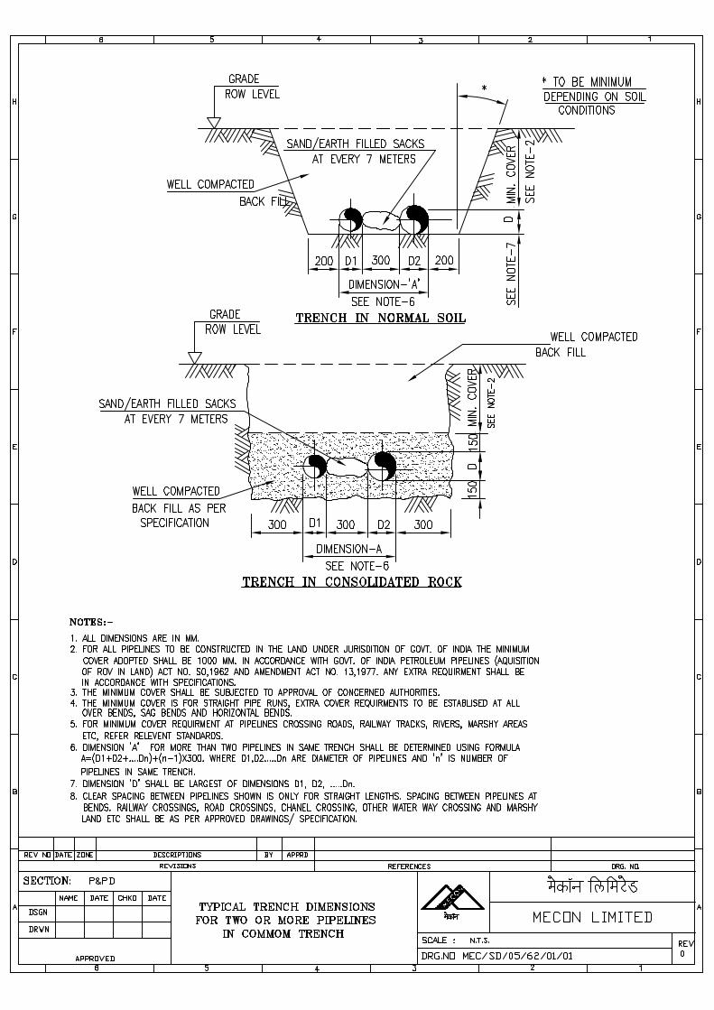
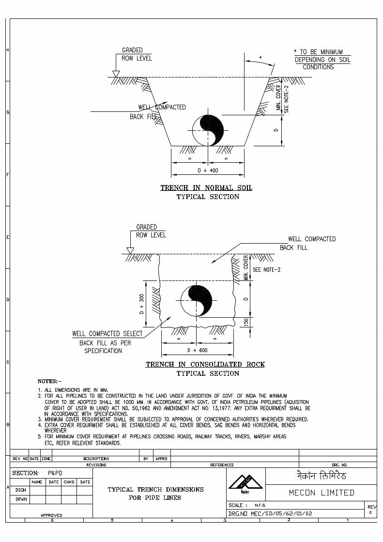
\\Akjha\work contrac\standard TS for Pipe Line WC (Vol-II) MASTER FOLDER\02A welding onshore gas pipeline\Welding of Onshore Gas Pipelines with addendum - I 02A.doc
SPECIFICATIONFOR
WELDING OF ONSHORE GAS PIPELINES
SPECIFICATION NO. MEC/S/05/62/02 A
(PROCESS & PIPING DESIGN SECTION)MECON LIMITED
DELHI - 110 092
\\Akjha\work contrac\standard TS for Pipe Line WC (Vol-II) MASTER FOLDER\02A welding onshore gas pipeline\Welding of Onshore Gas Pipelines with addendum - I 02A.doc
MECON LIMITEDREGD. OFF: RANCHI (BIHAR)
PROCESS & PIPINGDESIGN SECTION
NEW DELHI
STANDARD SPECIFICATION
TITLE SPECIFICATION NO. PAGE 1 OF 48WELDING OF ONSHORE GASPIPELINES
MEC/S/05/62/02 REVISION 0
C O N T E N T S
01. SCOPE
02. APPLICABLE CODES, STANDARDS & SPECIFICATIONS
03. MATERIAL SPECIFICATIONS
04. WELDING CONSUMABLES
05. EQUIPMENT & ACCESSORIES
06. WELDING PROCESSES
07. BEVEL CLEANING AND BEVEL INSPECTION
08. ALIGNMENT AND SPACING
09. WEATHER CONDITIONS
10. WELDING
11. HEAT TREATMENT
12. INSPECTION AND TESTING
13. REPAIR OF WELDS
14. DESTRUCTIVE TESTING
15. ULTRASONIC INSPECTION
16. RADIOGRAPHY
1 Sheet No.
Rev Description Date
PREPARED BY CHECKED BY APPROVED BY
\\Akjha\work contrac\standard TS for Pipe Line WC (Vol-II) MASTER FOLDER\02A welding onshore gas pipeline\Welding of Onshore Gas Pipelines with addendum - I 02A.doc
MECON LIMITEDREGD. OFF: RANCHI (BIHAR)
PROCESS & PIPINGDESIGN SECTION
NEW DELHI
STANDARD SPECIFICATION
TITLE SPECIFICATION NO. PAGE 2 OF 48WELDING OF ONSHORE GASPIPELINES
MEC/S/05/62/02 REVISION 0
C O N T E N T S
Annexure-I : Electrode Qualification Test Record
Annexure-II : Stress Relief Heat Treatment Procedure Specification
Annexure-III : Welding Procedure Qualification Test Record
Annexure-IV : Welder Qualification Test Record
Annexure-V : Welders Identification Card
Annexure-VI : Radiographic Procedure for Pipe Welding
PREPARED BY CHECKED BY APPROVED BY
\\Akjha\work contrac\standard TS for Pipe Line WC (Vol-II) MASTER FOLDER\02A welding onshore gas pipeline\Welding of Onshore Gas Pipelines with addendum - I 02A.doc
MECON LIMITEDREGD. OFF : RANCHI (BIHAR)
PROCESS & PIPINGDESIGN SECTION
NEW DELHI
STANDARD SPECIFICATION
TITLE SPECIFICATION NO. PAGE 3 OF 48WELDING OF ONSHORE GASPIPELINES
MEC/S/05/62/02 REVISION
01. SCOPE
This specification stipulates requirements for fabrication of all types of weldedjoints in carbon steel piping systems covering the pipeline and its facilities, whichwill include the following:
• All line pipe joints of the longitudinal and circumferential butt welded andsocket welded types.
• Branch connections
• Joints in welded/ fabricated piping components.
• Attachments of castings, forgings, flanges and supports to pipes.
• Attachments of smaller connections for vents/ drain pipes and tappings forinstrumentation.
Note: Any approval accorded to the Contractor shall not absolve him of hisresponsibilities and guarantees.
02. APPLICABLE CODES, STANDARDS & SPECIFICATIONS
All welding works, equipment for welding, heat treatment, other auxiliaryfunctions and the welding personnel shall meet the requirements of the latesteditions of the following codes, standards and specifications as listed below :-
• Code for Gas Transmission and Distribution Piping System (ANSI B31.8).
• Standard for welding of Pipelines and Related Facilities (API 1104).
• Specification for welding Electrodes and Filler Materials (ASME Sec. II C).
• Non Destructive examination (ASME Sec. V).
03. MATERIAL SPECIFICATIONS
• In general carbon steel is used in this specification. The details of materialspecifications will be given in a welding Specification Chart attachedalongwith other project data sheets.
\\Akjha\work contrac\standard TS for Pipe Line WC (Vol-II) MASTER FOLDER\02A welding onshore gas pipeline\Welding of Onshore Gas Pipelines with addendum - I 02A.doc
MECON LIMITEDREGD. OFF : RANCHI (BIHAR)
PROCESS & PIPINGDESIGN SECTION
NEW DELHI
STANDARD SPECIFICATION
TITLE SPECIFICATION NO. PAGE 4 OF 48WELDING OF ONSHORE GASPIPELINES
MEC/S/05/62/02 REVISION
• The CONTRACTOR will keep a record of test certificates of all the materialsfor the reference of the welding engineer.
04. WELDING CONSUMABLES
The electrode shall be suitable for the welding process recommended and basemetal used. Physical properties of the welds produced by an electroderecommended for the welding of a particular base metal shall not be lower thanthe minimum values specified for the base metal unless otherwise specified inWelding Specification Chart and shall correspond to the physical properties of theclass of electrode adopted. The choice of electrode shall be made afterconducting the required tests on the electrodes as per relevant standards, andshall be the sole prerogative of the COMPANY.
The welding electrodes/ filler wires supplied by the CONTRACTOR shall conformto the class specified in the welding specification chart. The materials shall be ofthe make approved by the COMPANY.
The CONTRACTOR shall submit batch test certificates from the electrodemanufacturers giving details of physical and chemical tests carried out by themfor each batch of electrode to be used.
Electrode Qualification test records shall be submitted as per Annexure-I withrespect to the electrodes tested by the CONTRACTOR and submitted forapproval of the COMPANY.
The CONTRACTOR shall provide at his own expenses all the weldingconsumbles necessary for the execution of the job such as electrodes, oxygen,acetylene etc. and the same shall be approved in advance by the Purchaser/Consultant.
The electrodes used shall be free from rust, oil grease, earth and other foreignmatter which affect the quality of welding.
All electrodes shall be purchased in sealed containers and stored properly toprevent deterioration. The electrodes removed from the containers (exceptcellulosic coated electrodes) shall be kept in holding ovens at the temperaturerecommended by the electrode manufacturer. Ovens shall be used for lowhydrogen electrodes only. Out-of-the oven time of electrodes, before they areconsumed, shall not exceed the limits recommended by the electrodemanufacturer. The electrodes shall be handled with care to avoid any damage tothe flux covering.
\\Akjha\work contrac\standard TS for Pipe Line WC (Vol-II) MASTER FOLDER\02A welding onshore gas pipeline\Welding of Onshore Gas Pipelines with addendum - I 02A.doc
MECON LIMITEDREGD. OFF : RANCHI (BIHAR)
PROCESS & PIPINGDESIGN SECTION
NEW DELHI
STANDARD SPECIFICATION
TITLE SPECIFICATION NO. PAGE 5 OF 48WELDING OF ONSHORE GASPIPELINES
MEC/S/05/62/02 REVISION
Different grades of electrodes shall be stored separately. Cellulosic electrodesused shall however be used as per specific recommendations of manufacturer.
04.01 Shielding Gas
The composition and purity of shielding gas when required by the weldingprocesses other than shielded metal arc welding, when permitted by theCOMPANY, shall have prior approval of the COMPANY. Where appropriate,gases or gas mixture of the following quality shall be used.
a) argon complying with BS 4365
b) carbon dioxide complying with type 1 specified in BS 4105
c) gas mixture that have been proved to be satisfactory as a result ofprocedure approval tests.
When a gas mixture is used which has specified additions, e.g. 2% 02,5% CO2the variation of such addition shall not exceed ± 10% of that stated. Moisturecontent shall correspond to a dew point of - 30°C or lower.
05. EQUIPMENT & ACCESSORIES
5.1 The CONTRACTOR shall have sufficient number of welding and cuttingequipment, auxiliaries and accessories of sufficient capacities to meet the targetschedule.
5.2 All the equipment for performing the heat treatment including transformers,thermocouples, pyro-meters, automatic temperature recorders with suitablecalibration arrangements, etc. shall be provided by the CONTRACTOR, at hisown expenses and these shall bear the approval of the COMPANY. Adequatemeans of measuring current and voltage shall be available.
5.3 Redoing of any work necessitated by faulty equipment or operation used by theCONTRACTOR, will be done at his own expense.
\\Akjha\work contrac\standard TS for Pipe Line WC (Vol-II) MASTER FOLDER\02A welding onshore gas pipeline\Welding of Onshore Gas Pipelines with addendum - I 02A.doc
MECON LIMITEDREGD. OFF : RANCHI (BIHAR)
PROCESS & PIPINGDESIGN SECTION
NEW DELHI
STANDARD SPECIFICATION
TITLE SPECIFICATION NO. PAGE 6 OF 48WELDING OF ONSHORE GASPIPELINES
MEC/S/05/62/02 REVISION
06. WELDING PROCESSES
6.1 Welding of various materials under this specification shall be carried out usingShielded Metal Arc Welding process (SMAW) with the approval of theCOMPANY.
6.2 The welding processes to be employed are given in the welding specificationchart. Any deviation desired by the CONTRACTOR shall be obtained through theexpress consent of the COMPANY.
6.3 Automatic process shall be employed only with the express approval of theCOMPANY. The welding procedure adopted and consumables used shall bespecifically approved.
6.4 A combination of different welding processes or a combination of electrodes ofdifferent classes/ makes could be employed for a particular joint only afterqualifying the welding procedures to be adopted and obtaining the approval ofthe COMPANY.
07. BEVEL CLEANING AND BEVEL INSPECTION
Line pipe supplied by COMPANY shall have bevel ends as specified in theapplicable specification for Line Pipe attached with the Bid Package. Anymodification thereto, if required by CONTRACTOR due to his special weldingtechnique shall be carried out by the CONTRACTOR at his own cost.
Before welding, all rust and foreign matter shall be removed from the bevelledends by power operated tools. This shall be effected inside and outside and for aminimum distance of 25mm from the edge of the weld bevel. The bevels shall bethoroughly inspected at this stage. If any of the ends of the pipe joints aredamaged to the extent that, in the opinion of COMPANY, satisfactory weldspacing cannot be obtained and local repair by grinding cannot be successfullydone, the damged ends shall be cut and re-bevelled to the satisfaction of theCOMPANY, with an approved bevelling machine. Manual cutting and weldrepairs of bevels is not allowed. Should laminations, split ends or inherentmanufacturing defects in the pipe be discovered, the lengths of pipe containingsuch defects shall be removed from the line to the satisfaction of COMPANY. Onpipes which have been cut back, a zone extending 25mm back from the newfield bevel, shall be ultrasonically tested to the requirement of the line pipespecification to ensure freedom from laminations. The new bevel shall besubjected to 100% visual and 100% dye penetrant/ MPI tests. A report shall bewritten for all testing and records kept.
\\Akjha\work contrac\standard TS for Pipe Line WC (Vol-II) MASTER FOLDER\02A welding onshore gas pipeline\Welding of Onshore Gas Pipelines with addendum - I 02A.doc
MECON LIMITEDREGD. OFF : RANCHI (BIHAR)
PROCESS & PIPINGDESIGN SECTION
NEW DELHI
STANDARD SPECIFICATION
TITLE SPECIFICATION NO. PAGE 7 OF 48WELDING OF ONSHORE GASPIPELINES
MEC/S/05/62/02 REVISION
08. ALIGNMENT AND SPACING
Immediately prior to line-up CONTRACTOR shall inspect the pipe ends insideand outside for damage, dents, laminations etc. Pipe for welding shall be set up,correctly spaced, allowing for temperature changes during welding, in correctalignment and shall in no circumstances be sprung into position. Temporaryattachments of any kind shall not be welded to the pipe. Welds joining thesections of the pipelines, valve installation or similar welds classified as tie-inwelds shall be made in the trench. Otherwise the alignment and welding shall bemade alongside the ditch with the pipe supported on skids and back pad or othersuitable means approved by COMPANY, at least 500mm above the ground,unless approved by the COMPANY in specific cases.
Seam orientation of welded pipe shall be selected to ensure that at thecircumferential welds, the longitudinal welds shall be staggered in the top 90° ofthe pipeline, or 250mm whichever is the lesser. A longitudinal joint shall pass anappurtenance of a structural element at a minimum distance of 50mm. Should asection of the line containing uncompleted welds fall from the skids, theCONTRACTOR shall immediately inform COMPANY.
Every effort shall be made to reduce misalignment by the use of the clamp androtation of the pipes to obtain the best fit. For pipe of same nominal wallthickness off-set shall not exceed 1.6mm. The off set may be checked fromoutside using dial gauges. Any branch connection, sleeve, etc. shall be atleast150mm from any other weld. The welds for fittings shall be so located that the toeof the cold dressing is permissible only in cases of slight misalignment and mayonly be carried out with a bronze headed hammer. Hot dressing shall not bepermitted. When welding pipes of different wall thickness (as directed byCOMPANY) a special transition piece shall be used. This shall have a minimumof 1:4 taper. The welds shall be subject to both ultrasonic and radiographicinspection.
The root gap shall be accurately checked and shall conform to the qualifiedwelding procedure. The use of internal line-up clamps is mandatory for pipediameters 10" and above. However, in some cases (tie-in welds, flanges, fittings,diameter of pipe 10" etc.) where it is impossible to use internal clamps, anexternal line-up clamp may be used.
\\Akjha\work contrac\standard TS for Pipe Line WC (Vol-II) MASTER FOLDER\02A welding onshore gas pipeline\Welding of Onshore Gas Pipelines with addendum - I 02A.doc
MECON LIMITEDREGD. OFF : RANCHI (BIHAR)
PROCESS & PIPINGDESIGN SECTION
NEW DELHI
STANDARD SPECIFICATION
TITLE SPECIFICATION NO. PAGE 8 OF 48WELDING OF ONSHORE GASPIPELINES
MEC/S/05/62/02 REVISION
The internal line-up clamp shall not be released before the entire root pass hasbeen completed.
When as external line-up clamp is used, all spaces between bars or atleast 60%of the first pass shall be welded before the clamp is released and the piperemaining adequately supported on each side of the joint.
Segments thus welded shall be equally spaced around the circumference of thepipe. Slag, etc. shall be cleaned off and the ends of the segments shall beprepared by grinding, so as to ensure continuity of the weld bead.
09. WEATHER CONDITIONS
The parts being welded and the welding personnel shall be adequately protectedfrom rain and strong winds. In the absence of such a protection no welding shallbe carried out. The completed welds shall be suitably protected in case of badweather conditions.
10.0 WELDING
10.1 Root Pass
a) Root pass shall be made with electrodes/ filler wires recommended in thewelding specification chart attached along with other project data sheets.The size of the electrodes used shall be as per the approved weldingprocedure.
b) Position or roll welding may be permitted. Separate procedures shall besubmitted and qualified for up hill, down hill, vertical down and roll welding.The vertical up method of welding shall be sued for the root pass of thetie-ins, special crossings, fittings and special parts, filled welds, repairsand when an external line up clamp is used. The down hill welding may beused for root run welding of tie-ins and special crossings when (a) theedges are machined or have equivalent preparation (b) line up clamps areused and the fit up is geometrically and mechanically similar to one of theoridinary line welding without misalignment or uneveness.
c) The root pass of butt joints shall be executed properly so as to achieve fullpenetration with complete fusion of the root edges. Weld projection insidethe pipe shall not exceed 3mm wherever not specified by the applicablecode.
\\Akjha\work contrac\standard TS for Pipe Line WC (Vol-II) MASTER FOLDER\02A welding onshore gas pipeline\Welding of Onshore Gas Pipelines with addendum - I 02A.doc
MECON LIMITEDREGD. OFF : RANCHI (BIHAR)
PROCESS & PIPINGDESIGN SECTION
NEW DELHI
STANDARD SPECIFICATION
TITLE SPECIFICATION NO. PAGE 9 OF 48WELDING OF ONSHORE GASPIPELINES
MEC/S/05/62/02 REVISION
d) Any deviation desired from the recommended welding technique andelectrodes indicated in the welding specification chart shall be adoptedonly after obtaining express approval of the COMPANY.
e) Welding shall be continuous and uninterrupted during a pass.
f) On completion of each run, craters, welding irreigularities, slag, etc., shallbe removed by grinding and chiselling.
g) While the welding is in progress care shall be taken to avoid any kindofmovement of the components, shocks, vibration and stresses to preventoccurance of weld cracks.
h) Fillet welds shall be made by shielded metal arc welding processirrespective of the thickness and class of piping. Electrode size shall notexceed 3.25mm diameter for socket joints. Atleast two passes shall bemade on socket weld joints
i) Peening shall not be used.
10.2 Joint Completion
In case of manual welding, the first pass shall be carried out by a minimum of twowelders, working simultaneously and so placed as to cause minimum distortionof the pipe.
The number of welders and the allowable welding sequences shall be as thoselaid down in the qualified welding procedure specification. Once the deposit ofthe first pass has been started, it must be completed as rapidly as possible,reducing interruptions to the minimum. The welding and wire speed shall beapproximately same as that established in the qualified welding procedurespecification.
The pipe shall always be adequately supported and must not be pumped orshaken during welding. The clamp shall be removed, as indicated in clause 8.0above. Before starting the second pass, the first pass shall be cleaned andflattened with rotating grinders.
The interruption between completion of the first pass and starting the secondpass shall be as stated in the procedure specification, normally not exceedingfour minutes.
\\Akjha\work contrac\standard TS for Pipe Line WC (Vol-II) MASTER FOLDER\02A welding onshore gas pipeline\Welding of Onshore Gas Pipelines with addendum - I 02A.doc
MECON LIMITEDREGD. OFF : RANCHI (BIHAR)
PROCESS & PIPINGDESIGN SECTION
NEW DELHI
STANDARD SPECIFICATION
TITLE SPECIFICATION NO. PAGE 10 OF 48WELDING OF ONSHORE GASPIPELINES
MEC/S/05/62/02 REVISION
For crack prevention a top and bottom reinforcement of at least one electrodeshall be applied before lowering the pipe on the skid.
The welding speed selected shall enable production of a bead which issufficiently thick and which shows no undercutting.
The time lapse between second and third pass shall be as stated in theprocedure specification, normally not exceeding five minutes. After completion ofthe third or following passes, welding operations may be suspended, so allowingthe joint to cool down, provided that the thickness of the weld metal deposited isequal to at least 50% of the pipe thickness. Upon restarting, depending on thematerials, wall thickness and welding process, a preheating to atleast 100°Cshall be carried out. Subsequent passes up to weld completion shall be protectedto avoid rapid cooling, if meteorological conditions so dictate. Cleaning betweenpasses shall be done carefully so as to reduce the possibility of inclusions.
Electrodes starting and finishing points shall be staggered from pass to pass.Arc-strikes outside the bevel on the pipe surface are not permitted. Arc - strike orarc-burn on the pipe surface outside the weld, which are caused accidentally byelectrical arcs between the electrodes, electrode holder, welding cable shall beremoved by grinding in accordance with a procedure approved by COMPANYand the repair checked by ultrasonic, radiographic, magnetic particle ordyepenetrant tests which the COMPANY feels necessary. The pipe wallthickness after grinding shall not be less that the minimum thickness limitpermitted for the pipe. Repair of arc-strikes by welding is prohibited.
The completed weld shall be carefully brushed and cleaned and shall appear freefrom spatters, scales, etc.
These requirements apply not only to completed welds but also to the bare stripat least so wide so as to allow full skid examination at both ends of the pipe toallow a good ultrasonic inspection when it is required.
11.0 HEAT TREATMENT
11.1 Preheating
a) Preheating requirements for the various materials shall be as per thewelding specification chart.
\\Akjha\work contrac\standard TS for Pipe Line WC (Vol-II) MASTER FOLDER\02A welding onshore gas pipeline\Welding of Onshore Gas Pipelines with addendum - I 02A.doc
MECON LIMITEDREGD. OFF : RANCHI (BIHAR)
PROCESS & PIPINGDESIGN SECTION
NEW DELHI
STANDARD SPECIFICATION
TITLE SPECIFICATION NO. PAGE 11 OF 48WELDING OF ONSHORE GASPIPELINES
MEC/S/05/62/02 REVISION
b) Preheating shall be performed using resistance or induction/ heatingmethods. Preheating by gas burners, utilising acetylene or propane gasmay also be carried out. Oxypropane gas may be used with thepermission of the COMPANY under careful supervision.
c) Preheating shall extend uniformly to atleast three times the thickness ofthe joint, but not less than 50mm, on both sides of the weld.
d) Preheating temperature shall be maintained over the whole length of thejoint during welding. Temperature indicating crayons or other temperatureindicating devices shall be provided by the CONTRACTOR to check thetemperature.
11.2 Postweld Heat Treatment
a) Post weld heat treatment, wherever required for joints between pipes andfittings, pipe body and supports shall be carried out by theCONTRACTOR at his expense as per the relevant specifications,applicable standards and the instructions of the COMPANY.
b) The heat treatment of welded joints shall be carried out as per therequirements laid down in ANSI B31.8 and other special requirementsmentioned in welding specification chart.
c) The CONTRACTOR shall submit for the approval of the COMPANY, wellbefore carrying out actual heat treatments the details of the post weld heattreatment procedure, as per Annexure-II attached, that he proposes toadopt for each of the materials/ assembly/ part involved.
d) Post weld heat treatment shall be done in a furnace or by using an electricresistance or induction heating equipment, as decided by the COMPANY.
e) While carrying out local post weld heat treatment, technique of applicationof heat must ensure uniform temperature attainment at all points of theportion being heat treated. Care shall be taken to ensure that width ofheated band over which specified post weld heat treatment temperature isattained is atleat as that specified in the relevant applicable standards/codes.
\\Akjha\work contrac\standard TS for Pipe Line WC (Vol-II) MASTER FOLDER\02A welding onshore gas pipeline\Welding of Onshore Gas Pipelines with addendum - I 02A.doc
MECON LIMITEDREGD. OFF : RANCHI (BIHAR)
PROCESS & PIPINGDESIGN SECTION
NEW DELHI
STANDARD SPECIFICATION
TITLE SPECIFICATION NO. PAGE 12 OF 48WELDING OF ONSHORE GASPIPELINES
MEC/S/05/62/02 REVISION
The width of the heated band centred on the weld shall at least be equalto the width of weld plus 2" (50mm). The temperature gradient shall besuch that the length of the material on each side of the weld, at atemperature exceeding half the heat treatment temperature, is atleast 2.5rt wherer is the bore radius and t is the pipe thickness at the weld.
f) Throughout the cycle of heat treatment, the portion outside the heat bandshall be suitably wrapped with insulation so as to avoid any harmfultemperature gradient on the exposed surface of pipe. For this purposetemperature at the exposed surface of the pipe shall not be allowed toexceed 400°C.
g) The temperature attained by the portion under heat treatment shall berecorded by means of thermocouple pyrometers. Adequate number ofthermocouples shall be attached to the pipe directly at equally spacedlocations along the periphery of the pipe joint. The minimum number ofthermocouples attached per joint shall be 2 upto 10" dia and 3 for 12" diaand above. However, the COMPANY can increase the required minimumnumber of thermocouples to be attached, if found necessary.
h) Automatic temperature recorders which have been suitably calibratedshall be employed. The calibration chart of each recorder shall besubmitted to the COMPANY prior to starting the heat treatment operationand its approval shall be obtained.
i) Immediately on completion of the heat treatment, the post weld heattreatment charts/ records alongwith the hardness test results on the weldjoints (whenever required as per the welding specification chart) shall besubmitted to COMPANY for its approval.
j) Each joint shall bear an identification number which shall be maintained inthe piping sketch to be prepared by the CONTRACTOR. The jointidentification number shall appear on the corresponding post weld heattreatment treatment charts. The same identification numbers shall also befollowed for identification on corresponding radiographic films. The chartcontaining the identification number and piping sketch shall be submittedto the COMPANY in suitable folders.
\\Akjha\work contrac\standard TS for Pipe Line WC (Vol-II) MASTER FOLDER\02A welding onshore gas pipeline\Welding of Onshore Gas Pipelines with addendum - I 02A.doc
MECON LIMITEDREGD. OFF : RANCHI (BIHAR)
PROCESS & PIPINGDESIGN SECTION
NEW DELHI
STANDARD SPECIFICATION
TITLE SPECIFICATION NO. PAGE 13 OF 48WELDING OF ONSHORE GASPIPELINES
MEC/S/05/62/02 REVISION
k) Vickers hardness/ Brinnel hardness of the heat affected zone as well as ofthe weld metal, after heat treatment shall be measured using a suitablehardness tester and shall not exceed the maximum hardness specified inthe welding specification chart. The weld joint shall be subjected to reheattreatment, when hardness measured exceeds the specified limit, at theCONTRACTOR's own expense.
l) The CONTRACTOR shall arrange for the hardness testing and shallmaintain the records of all the joints tested. These records shall bechecked by the COMPANY.
12.0 INSPECTION AND TESTING
12.1 Generala) The COMPANY's Inspector shall have free access to all concerned areas,
where the actual work is being performed. The CONTRACTOR shall bealso provide the COMPANY's inspector all means and facilities necessaryto carry out inspection.
b) The COMPANY is entitled to depute its own inspector to the shop or fieldwhere pre-fabrication and erection of pipelines are being done, with (butnot limited to) the following objectives :-
i. To check the conformance to relevant standards/ specificationsand suitability of various welding equipment and the weldingperformance.
ii. To supervise the welding procedures qualification.
iii. To supervise the welder's performance qualification.
iv. To carry out visual/NDT examination of the weldings.
v. To check whether shop/ field welding is being executed is inconformity with the relevant specification and codes of practicefollowed in pipe construction.
c) CONTRACTOR shall intimate sufficiently in advance the commencementof qualification tests, welding works and acceptance tests, to enable theCOMPANY's inspector to be present to supervise the same.
\\Akjha\work contrac\standard TS for Pipe Line WC (Vol-II) MASTER FOLDER\02A welding onshore gas pipeline\Welding of Onshore Gas Pipelines with addendum - I 02A.doc
MECON LIMITEDREGD. OFF : RANCHI (BIHAR)
PROCESS & PIPINGDESIGN SECTION
NEW DELHI
STANDARD SPECIFICATION
TITLE SPECIFICATION NO. PAGE 14 OF 48WELDING OF ONSHORE GASPIPELINES
MEC/S/05/62/02 REVISION
12.2 Welding Procedure Qualification
a) Welding procedure qualification shall be carried out in accordance with therelevant requirements of API 1104 latest edition or other applicable codesand other job requirements by the CONTRACTOR at his expense. TheCONTRACTOR shall submit the welding procedure specification chartformat as per Annexure-III (attached) immediately after the receipt of theorder.
b) COMPANY's inspector will review, check and approve the weldingprocedure submitted and shall release the procedure for procedurequalification tests. The procedure qualification test shall be carried out bythe CONTRACTOR under field conditions at his own expense. A completeset of test results in format as per Annexure-III (attached) shall besubmitted to the COMPANY's Inspector for approval immediately aftercompleting the procedure qualification test and atleast 2 weeks before thecommencement of actual work. Standard tests as specified in the codeshall be carried out in all cases. In addition to these, tests, other tests likeradiography, macro/ micro examination, hardness tests, dye penetrantexamination, charphy V-notch etc. shall be carried out on specimens. Itshall be the responsibility of the CONTRACTOR to carry out all the testsrequired to the satisfaction of the COMPANY's Inspector. The destructivetesting of welded joints shall be as per Clause 14.0.
12.3 Welder's Qualification
a) Welders shall be qualifed in accordance with the API 1104 and otherapplicable specifications by the CONTRACTOR at his expense. The buttweld test pieces of the qualification test shall meet the radiographic testrequirements specified in Clause 12.5 and 16.0 of this specification. TheCOMPANY's Inspector shall witness the test and certify the qualification ofeach welder separately. Only those welders who have been approved bythe COMPANY's Inspector shall be employed for welding.CONTRACTOR shall submit the welder qualification test reports in thestandard format as shown in Annexure-IV and obtain express approval,before commencement of the work. It shall be the responsibility ofCONTRACTOR to carry out qualification tests of welders.
\\Akjha\work contrac\standard TS for Pipe Line WC (Vol-II) MASTER FOLDER\02A welding onshore gas pipeline\Welding of Onshore Gas Pipelines with addendum - I 02A.doc
MECON LIMITEDREGD. OFF : RANCHI (BIHAR)
PROCESS & PIPINGDESIGN SECTION
NEW DELHI
STANDARD SPECIFICATION
TITLE SPECIFICATION NO. PAGE 15 OF 48WELDING OF ONSHORE GASPIPELINES
MEC/S/05/62/02 REVISION
b) The welders shall always have in their possession the identification cardas shown in Annexure-V and shall produce it on demand by theCOMPANY's Inspector. It shall be the responsibility of the CONTRACTORto issue the identity cards after it has been duly certified by theCOMPANY.
c) No welder shall be permitted to work without the possession of identitycards.
d) If a welder is found to perform a type of welding or in a position for whichhe is not qualified, he shall be debarred from doing any further work. Allwelds performed by an unqualfiied welder shall be cut and redone by aqualified welder at the expense of the CONTRACTOR.
12.4 Visual Inspection
Inspection of all welds shall be carried out by COMPANY as per the latesteditions of the applicable codes and specifications. All finished welds shall bevisually inspected for parallel and axial alignment of the work, excessivereinforcement, concavity of welds, shrinkage, cracks, under-cuts, dimensions ofthe weld, surface porosity and other surface defects. Undercutting adjacent to thecompleted weld shall not exceed the limits specified in the applicable standard/code.
12.5 Non Destructive Examination
The non destructive examination shall mainly consist of examination using x-rayradiography as detailed in Clause 16.0.
Radiographic examination of one hundred percent (100%) girth welds will berequired by the COMPANY.
For 150# Rating Pipeline, welds shall meet the standards of acceptability as setforth in API 1104. However for higher class rating pipeline welds shall meet thestandards of acceptability as set forth in API 1104 and as well as therequirements laid in subsequent paragraphs.
The CONTRACTOR shall make all the arrangements for the radiographicexamination of work covered by the specification at his expense.
The COMPANY will review all the radiographs of welds and inform theCONTRACTOR regarding acceptable welds. The decision of the COMPANYshall be final and binding in the regard.
\\Akjha\work contrac\standard TS for Pipe Line WC (Vol-II) MASTER FOLDER\02A welding onshore gas pipeline\Welding of Onshore Gas Pipelines with addendum - I 02A.doc
MECON LIMITEDREGD. OFF : RANCHI (BIHAR)
PROCESS & PIPINGDESIGN SECTION
NEW DELHI
STANDARD SPECIFICATION
TITLE SPECIFICATION NO. PAGE 16 OF 48WELDING OF ONSHORE GASPIPELINES
MEC/S/05/62/02 REVISION
i. Any length of inadequate penetration of the root bead as defined by API-1104 is not acceptable except that root concavity is allowed as per API1104.
ii. Any amount of incomplete fusion at the root of the joint as detailed in para6.3.4 of API 1104 sixteenth edition May, 1983 (Ref. Fig. 13) is consideredunacceptable.
iii. Unrepaired burn through areas are unacceptable.
All requirements mentioned in the specification shall be arranged and executedby the CONTRACTOR through his own resources. In addition, for pipes with wallthickness 9.5mm and above, ultrasonic inspection is required in the followingcases as per clause 15.0 of this specification.
a) On the first 100 welded joints corresponding to each automatic (GTAW/GMAW) welding procedure used.
b) When 20mm or more are cut from the pipe end as supplied, the ends shallbe ultrasonically inspected for an additional length of 20mm to assure nolamination exist.
c) When welds are repaired.
d) When in the opinion of COMPANY, ultrasonic inspection is required toconfirm or clarify defects indicated by radiography.
e) When automatic procedure is used at least 10 cm on each weld shall beultrasonically inspected at COMPANY's discretion.
In addition, ultrasonic inspection may be required for certain critical weldings ofthe pipeline (i.e. tie-ins, welding of valves, flanges) randomly selected atCOMPANY's discretion. All fillet and groove welds other than those radiographedshall by subjected to dye penetrant/ MP inspection. The non-destructive testsystem used for inspecting welds must be approved by the COMPANY.
Weld quality is judged on the basis of the acceptability criteria mentioned below:
\\Akjha\work contrac\standard TS for Pipe Line WC (Vol-II) MASTER FOLDER\02A welding onshore gas pipeline\Welding of Onshore Gas Pipelines with addendum - I 02A.doc
MECON LIMITEDREGD. OFF : RANCHI (BIHAR)
PROCESS & PIPINGDESIGN SECTION
NEW DELHI
STANDARD SPECIFICATION
TITLE SPECIFICATION NO. PAGE 17 OF 48WELDING OF ONSHORE GASPIPELINES
MEC/S/05/62/02 REVISION
Any weld which as a result of radiographic and/ or ultrasonic examination in theopinion of COMPANY exhibits imperfections greater than the limits stated in API-1104 latest edition or as superseded in this article shall be considered defectiveand shall so be marked with an identification paint marker.
In addition to the API-1104 requirements, the welds containing cracks includingcrater cracks regardless of size of location is unacceptable.
1. Any length of inadequate penetration of the root bead as defined by API-1104 is not acceptable except that root concavity is allowed as per API1104.
2. Any amount of incomplete fusion at the root of the joint as detailed in API1104 is considered unacceptable.
3. Unrepaired burn through areas are unacceptable.
Suitable records shall be maintained by the CONTRACTOR as desired by theCOMPANY on the day to day work done on welding, radiography, ultrasonictesting. The CONTRACTOR shall present the records to the COMPANY on dayto day basis and whenever demanded, for approval.
12.6 Destructive Testing
The COMPANY has the authority to order the cutting of upto 0.1% of the totalnumber of welds completed for destructive testing at no extra cost of COMPANY.The destructive testing of weld joints shall be made as per Clause 14.0.
In addition, welds already cut out for defects for any reason may also besubjected to destructive testing. The sampling and the re-execution of welds shallbe carried out by the CONTRACTOR at his own expense. If the results areunsatisfactory, welding operations shall be suspended and may not be restarteduntil the causes have been identified and the CONTRACTOR has adoptedmeasures which guarantee acceptable results. If it is necessary in theCOMPANY's opinion the procedure shall be re-qualified. The weld jointrepresented by unsatisfactory welds shall stand rejected unless investigationprove otherwise.
13.0 REPAIR OF WELDS
13.1 With the prior permission of COMPANY, welds which do not comply with thestandards of acceptability shall be repaired or the joint cut out and re-welded.
\\Akjha\work contrac\standard TS for Pipe Line WC (Vol-II) MASTER FOLDER\02A welding onshore gas pipeline\Welding of Onshore Gas Pipelines with addendum - I 02A.doc
MECON LIMITEDREGD. OFF : RANCHI (BIHAR)
PROCESS & PIPINGDESIGN SECTION
NEW DELHI
STANDARD SPECIFICATION
TITLE SPECIFICATION NO. PAGE 18 OF 48WELDING OF ONSHORE GASPIPELINES
MEC/S/05/62/02 REVISION
A separate welding procedure specification sheet shall be formulated andqualified by CONTRACTOR for repair welds simulating the proposed repair to becarried out. Separate procedures are required to be qualified for (a) thoroughthickness repair (b) external repair and (c) internal repair. Welders shall bequalified in advance for repairs. The root pass, for repairs opening the root, shallbe done by the vertical uphill technique. The procedure shall be proven bysatisfactory procedure tests to API 1104 including the special requirement of thespecification, and shall also be subject to metalographic examination, hardnesssurveys and Charpy tests to determine the effects of repair welding on theassociated structure.
Root sealing or single pass repair deposit shall not be allowed. Internal rootdefects shall be ground thoroughly and welded with a minimum of two passes.However, while grinding for repairs, care shall be taken to ensure that no grindingmarks are made on the pipe surface anywhere.
The repair shall be subjected, as a minimum requirement to the same testing andinspection requirements as the original weld. The re-radiography of repaired weldshall be limited to 6” weld length on either edge of the repaired area. A 100%ultrasonic test shall be done at the repaired area externally. Any repaired areathat is wide, irregular or rough shall be rejected and a full cut out shall be done.
Repairs are limited to a maximum of 30% of the weld length. Welds not meetingthe specification after one repair shall be cut out depending upon the extent ofrepair. A report of all repairs shall be maintained by CONTRACTOR.
13.2 Limitations on Repairs
Only one attempt at repair of any region is permitted. Repairs are limited to amaximum of 30% of the weld length measuring over cap. Welds containingcracks shall be cut out and rebevelled to make a joint.
\\Akjha\work contrac\standard TS for Pipe Line WC (Vol-II) MASTER FOLDER\02A welding onshore gas pipeline\Welding of Onshore Gas Pipelines with addendum - I 02A.doc
MECON LIMITEDREGD. OFF : RANCHI (BIHAR)
PROCESS & PIPINGDESIGN SECTION
NEW DELHI
STANDARD SPECIFICATION
TITLE SPECIFICATION NO. PAGE 19 OF 48WELDING OF ONSHORE GASPIPELINES
MEC/S/05/62/02 REVISION
13.3 Weld Rejected by Accumulation of Defects
Where a weld is rejected by the accumulation of defect clause, as defined by API1104 and this specification, repairs within these limitations are permitted. Defectsin the filling and capping passes shall be repaired preferentially.
14. DESTRUCTIVE TESTING OF WELDED JOINT - BUTT WELDS
14.1 Preparation
Having passed the visual and the non-destructive-inspection the test weld shallbe subject to mechanical test.
After satisfactory completion of all visual and non-destructive testing the test weldshall be set aside for a period not less than 24hours. No further work on the testweld and no cutting of test specimens from the weld shall be performed until aperiod of at least 24 hours has expired.
Weld specimens shall be taken from the positions indicated in Fig. 1 of thisspecification from areas as free from defects as possible; for this reason it isnecessary to take the previous non-destructive tests into account. The minimumnumber of tests to be carried out is given in Table-1 of this specification.
The tests shall be carried out in laboratories approved by the COMPANY. Thespecimens shall be prepared in accordance with the figures given in theparagraphs which refer to the individual tests.
14.2 Tensile Strength
Specimens shall be taken from the position indicated in Fig. 1 & 1A of thisspecification. Two ISO type specimens and two API - type specimens shall betaken.
The ISO test specimen are shown in Fig. 2 of this specification.14.2.1 Method
The test shall be carried out in accordance with ISO:375.

\\Akjha\work contrac\standard TS for Pipe Line WC (Vol-II) MASTER FOLDER\02A welding onshore gas pipeline\Welding of Onshore Gas Pipelines with addendum - I 02A.doc
MECON LIMITEDREGD. OFF : RANCHI (BIHAR)
PROCESS & PIPINGDESIGN SECTION
NEW DELHI
STANDARD SPECIFICATION
TITLE SPECIFICATION NO. PAGE 20 OF 48WELDING OF ONSHORE GASPIPELINES
MEC/S/05/62/02 REVISION
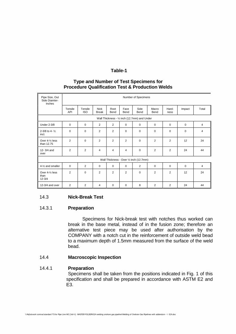
\\Akjha\work contrac\standard TS for Pipe Line WC (Vol-II) MASTER FOLDER\02A welding onshore gas pipeline\Welding of Onshore Gas Pipelines with addendum - I 02A.doc
Table-1
Type and Number of Test Specimens forProcedure Qualification Test & Production Welds
Pipe Size, OutSide Diamter-
Inches
Number of Specimens
TensileAPI
TensileISO
NickBreak
RootBend
FaceBend
SideBend
MacroBend
Hard-ness
Impact Total
Wall Thickness - ½ inch (12.7mm) and Under
Under 2-3/8 0 0 2 2 0 0 0 0 0 4
2-3/8 to 4- ½incl.
0 0 2 2 0 0 0 0 0 4
Over 4-½ lessthan 12.75
2 0 2 2 2 0 2 2 12 24
12- 3/4 andover
2 2 4 4 4 0 2 2 24 44
Wall Thickness - Over ½ inch (12.7mm)
4-½ and smaller 0 2 0 0 0 2 0 0 0 4
Over 4-½ lessthan12-3/4
2 0 2 2 2 0 2 2 12 24
12-3/4 and over 2 2 4 0 0 8 2 2 24 44
14.3 Nick-Break Test
14.3.1 Preparation
Specimens for Nick-break test with notches thus worked canbreak in the base metal, instead of in the fusion zone; therefore analternative test piece may be used after authorisation by theCOMPANY with a notch cut in the reinforcement of outside weld beadto a maximum depth of 1.5mm measured from the surface of the weldbead.
14.4 Macroscopic Inspection
14.4.1 PreparationSpecimens shall be taken from the positions indicated in Fig. 1 of this
specification and shall be prepared in accordance with ASTM E2 andE3.
\\Akjha\work contrac\standard TS for Pipe Line WC (Vol-II) MASTER FOLDER\02A welding onshore gas pipeline\Welding of Onshore Gas Pipelines with addendum - I 02A.doc
MECON LIMITEDREGD. OFF : RANCHI (BIHAR)
PROCESS & PIPINGDESIGN SECTION
NEW DELHI
STANDARD SPECIFICATION
TITLE SPECIFICATION NO. PAGE 21 OF 48WELDING OF ONSHORE GASPIPELINES
MEC/S/05/62/02 REVISION
The width of the macrosection has to be at least three times the width of theweld. The section is to be prepared by grinding and polishing and etched toclearly reveal the weld metal and heat affected zone.
14.4.2 Method
Specimens shall be carefully examined under the microscope, with amagnification of atleast 25 times (25:1). The COMPANY may ask for amacrograph with 5 times (5:1) magnification for DOCUMENTATION purposes.
14.4.3 Requirements
Under macroscopic examination, the welded joints shall show good penetrationand fusion, without any defect exceeding the limits stated in the evaluationcriteria of the nick break test.
14.5 Hardness Test
14.5.1 Preparation
The prepared macrosection is to be used for hardness testing using the Vickersmethod with 10 kg load Indentations are to be made along traverses eachapproximately 1mm below the surface on both sides of the weld.
In the weld metal a minimum of 6 indentations equally spaced along thetraverses are to be made. The HAZ indentations are to be made along thetraverses for approximately 0.5mm each into unaffected materials, and startingas close to the fusion line as possible.
One indentation on each side of the weld along each traverse is to be made onparent metal. Refer Fig.3. The indentations are to be made in the adjacentregions as well on the opposite sides of the macrosection along the specifiedtraverses.
14.5.2 Method
The test shall be carried out in accordance with Recommendation ISO R81,Vickers hardness, using a laboratory type machine controlled as pre-recommendation ISO R146 and using a diamond pyramid penetrator set at 2.37rad (136°) with a load of 10 kg.
\\Akjha\work contrac\standard TS for Pipe Line WC (Vol-II) MASTER FOLDER\02A welding onshore gas pipeline\Welding of Onshore Gas Pipelines with addendum - I 02A.doc
MECON LIMITEDREGD. OFF : RANCHI (BIHAR)
PROCESS & PIPINGDESIGN SECTION
NEW DELHI
STANDARD SPECIFICATION
TITLE SPECIFICATION NO. PAGE 22 OF 48WELDING OF ONSHORE GASPIPELINES
MEC/S/05/62/02 REVISION
14.5.3 RequirementsHardness value shall not exceed the limit specified in welding Specification chart.In case of a single reading having a slightly (+10 HV) higher value than thespecified limit, further indentations shall be made to check if the high value wasan isolated case.
All the hardness values contained from the heat affected zone shall not exceed100 HV with respect to the average hardness of the values obtained for the basemetal. If these additional tests give a hardness within the specification limit theslightly higher value may be accepted.
14.6 Charpy - V - Notch Impact Test14.6.1 Specimens shall be taken from the position indicated in Fig. 1 of this
specification. The test specimens will be prepared in accordance with ISO R148.Charpy V-notch specimens shall have dimensions as given in Fig. 3 of thisspecification.
Three test specimens shall be taken from each sample and they shall be cut andworked so that their length is transverse and perpendicular to the weld bead withthe notch position as shown in Fig. 4 of this specification. The notch shall beperpendicular to the roller surface. The test specimen width shall depend uponthe pipe wall nominal thickness as following :
Sl. Nominal Wall Thickness in mm Test Specimen width mmNo.1. Over 12 102. Over 9.5 and upto 12 7.53. From 7 upto 9.5 54. Less than 7 2.5
14.6.2 Test Method
The test shall be carried out as indicated in ISO R148 "Beam impact test V-notch".
Test pieces shall be immersed in a thermostatic bath and maintained at the testtemperature for at least 15 minutes. They shall then be placed in the testingmachine and broken within 5 seconds of their removal from the bath. The testtemperature shall be as mentioned in Special conditions of the Contract.
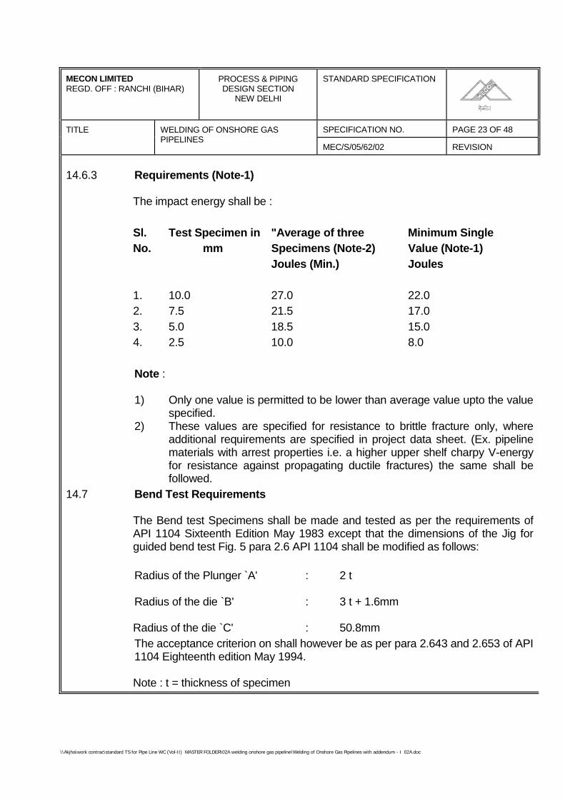
\\Akjha\work contrac\standard TS for Pipe Line WC (Vol-II) MASTER FOLDER\02A welding onshore gas pipeline\Welding of Onshore Gas Pipelines with addendum - I 02A.doc
MECON LIMITEDREGD. OFF : RANCHI (BIHAR)
PROCESS & PIPINGDESIGN SECTION
NEW DELHI
STANDARD SPECIFICATION
TITLE SPECIFICATION NO. PAGE 23 OF 48WELDING OF ONSHORE GASPIPELINES
MEC/S/05/62/02 REVISION
14.6.3 Requirements (Note-1)
The impact energy shall be :
Sl. Test Specimen in "Average of three Minimum SingleNo. mm Specimens (Note-2) Value (Note-1)
Joules (Min.) Joules
1. 10.0 27.0 22.02. 7.5 21.5 17.03. 5.0 18.5 15.04. 2.5 10.0 8.0
Note :
1) Only one value is permitted to be lower than average value upto the valuespecified.
2) These values are specified for resistance to brittle fracture only, whereadditional requirements are specified in project data sheet. (Ex. pipelinematerials with arrest properties i.e. a higher upper shelf charpy V-energyfor resistance against propagating ductile fractures) the same shall befollowed.
14.7 Bend Test Requirements
The Bend test Specimens shall be made and tested as per the requirements ofAPI 1104 Sixteenth Edition May 1983 except that the dimensions of the Jig forguided bend test Fig. 5 para 2.6 API 1104 shall be modified as follows:
Radius of the Plunger `A' : 2 t
Radius of the die `B' : 3 t + 1.6mm
Radius of the die `C' : 50.8mmThe acceptance criterion on shall however be as per para 2.643 and 2.653 of API1104 Eighteenth edition May 1994.
Note : t = thickness of specimen
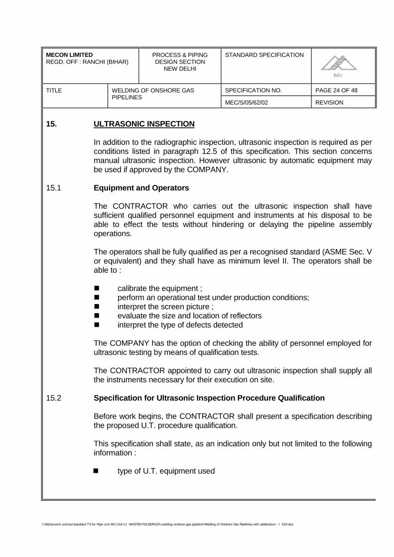
\\Akjha\work contrac\standard TS for Pipe Line WC (Vol-II) MASTER FOLDER\02A welding onshore gas pipeline\Welding of Onshore Gas Pipelines with addendum - I 02A.doc
MECON LIMITEDREGD. OFF : RANCHI (BIHAR)
PROCESS & PIPINGDESIGN SECTION
NEW DELHI
STANDARD SPECIFICATION
TITLE SPECIFICATION NO. PAGE 24 OF 48WELDING OF ONSHORE GASPIPELINES
MEC/S/05/62/02 REVISION
15. ULTRASONIC INSPECTION
In addition to the radiographic inspection, ultrasonic inspection is required as perconditions listed in paragraph 12.5 of this specification. This section concernsmanual ultrasonic inspection. However ultrasonic by automatic equipment maybe used if approved by the COMPANY.
15.1 Equipment and Operators
The CONTRACTOR who carries out the ultrasonic inspection shall havesufficient qualified personnel equipment and instruments at his disposal to beable to effect the tests without hindering or delaying the pipeline assemblyoperations.
The operators shall be fully qualified as per a recognised standard (ASME Sec. Vor equivalent) and they shall have as minimum level II. The operators shall beable to :
calibrate the equipment ;perform an operational test under production conditions;interpret the screen picture ;evaluate the size and location of reflectorsinterpret the type of defects detected
The COMPANY has the option of checking the ability of personnel employed forultrasonic testing by means of qualification tests.
The CONTRACTOR appointed to carry out ultrasonic inspection shall supply allthe instruments necessary for their execution on site.
15.2 Specification for Ultrasonic Inspection Procedure Qualification
Before work beqins, the CONTRACTOR shall present a specification describingthe proposed U.T. procedure qualification.
This specification shall state, as an indication only but not limited to the followinginformation :
type of U.T. equipment used
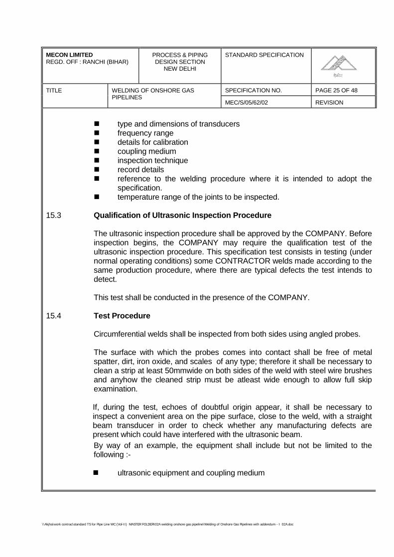
\\Akjha\work contrac\standard TS for Pipe Line WC (Vol-II) MASTER FOLDER\02A welding onshore gas pipeline\Welding of Onshore Gas Pipelines with addendum - I 02A.doc
MECON LIMITEDREGD. OFF : RANCHI (BIHAR)
PROCESS & PIPINGDESIGN SECTION
NEW DELHI
STANDARD SPECIFICATION
TITLE SPECIFICATION NO. PAGE 25 OF 48WELDING OF ONSHORE GASPIPELINES
MEC/S/05/62/02 REVISION
type and dimensions of transducersfrequency rangedetails for calibrationcoupling mediuminspection techniquerecord detailsreference to the welding procedure where it is intended to adopt thespecification.temperature range of the joints to be inspected.
15.3 Qualification of Ultrasonic Inspection Procedure
The ultrasonic inspection procedure shall be approved by the COMPANY. Beforeinspection begins, the COMPANY may require the qualification test of theultrasonic inspection procedure. This specification test consists in testing (undernormal operating conditions) some CONTRACTOR welds made according to thesame production procedure, where there are typical defects the test intends todetect.
This test shall be conducted in the presence of the COMPANY.
15.4 Test Procedure
Circumferential welds shall be inspected from both sides using angled probes.
The surface with which the probes comes into contact shall be free of metalspatter, dirt, iron oxide, and scales of any type; therefore it shall be necessary toclean a strip at least 50mmwide on both sides of the weld with steel wire brushesand anyhow the cleaned strip must be atleast wide enough to allow full skipexamination.
If, during the test, echoes of doubtful origin appear, it shall be necessary toinspect a convenient area on the pipe surface, close to the weld, with a straightbeam transducer in order to check whether any manufacturing defects arepresent which could have interfered with the ultrasonic beam.By way of an example, the equipment shall include but not be limited to thefollowing :-
ultrasonic equipment and coupling medium
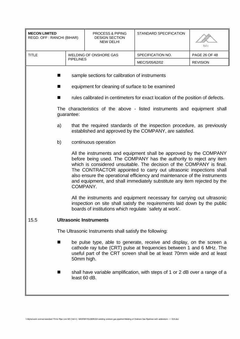
\\Akjha\work contrac\standard TS for Pipe Line WC (Vol-II) MASTER FOLDER\02A welding onshore gas pipeline\Welding of Onshore Gas Pipelines with addendum - I 02A.doc
MECON LIMITEDREGD. OFF : RANCHI (BIHAR)
PROCESS & PIPINGDESIGN SECTION
NEW DELHI
STANDARD SPECIFICATION
TITLE SPECIFICATION NO. PAGE 26 OF 48WELDING OF ONSHORE GASPIPELINES
MEC/S/05/62/02 REVISION
sample sections for calibration of instruments
equipment for cleaning of surface to be examined
rules calibrated in centimeters for exact location of the position of defects.
The characteristics of the above - listed instruments and equipment shallguarantee:
a) that the required standards of the inspection procedure, as previouslyestablished and approved by the COMPANY, are satisfied.
b) continuous operation
All the instruments and equipment shall be approved by the COMPANYbefore being used. The COMPANY has the authority to reject any itemwhich is considered unsuitable. The decision of the COMPANY is final.The CONTRACTOR appointed to carry out ultrasonic inspections shallalso ensure the operational efficiency and maintenance of the instrumentsand equipment, and shall immediately substitute any item rejected by theCOMPANY.
All the instruments and equipment necessary for carrying out ultrasonicinspection on site shall satisfy the requirements laid down by the publicboards of institutions which regulate `safety at work'.
15.5 Ultrasonic Instruments
The Ultrasonic Instruments shall satisfy the following:
be pulse type, able to generate, receive and display, on the screen acathode ray tube (CRT) pulse at frequencies between 1 and 6 MHz. Theuseful part of the CRT screen shall be at least 70mm wide and at least50mm high.
shall have variable amplification, with steps of 1 or 2 dB over a range of aleast 60 dB.
\\Akjha\work contrac\standard TS for Pipe Line WC (Vol-II) MASTER FOLDER\02A welding onshore gas pipeline\Welding of Onshore Gas Pipelines with addendum - I 02A.doc
MECON LIMITEDREGD. OFF : RANCHI (BIHAR)
PROCESS & PIPINGDESIGN SECTION
NEW DELHI
STANDARD SPECIFICATION
TITLE SPECIFICATION NO. PAGE 27 OF 48WELDING OF ONSHORE GASPIPELINES
MEC/S/05/62/02 REVISION
the regulation control shall be accurate to within ±1 db and this accuracyshall be certified by the instrument manufacturer.
may be powered by a battery or an electric generator. In the first case, theautonomy of operation (endurance) of the instrument shall be sufficient tocarry on working without frequent interruptions, and the instruments shallbe equipped with an automatic switch which switches it off when thebattery runs down; in the second case, there must be a voltage stabilisingdevice with a tolerance of ±2 Volts.
15.6 Probes
The probes used shall have dimensions, frequencies, and a refraction anglesuited to the type of steel, the diameter, the thickness of the pipe and to the jointdesign.
15.7 Reference Sample Pieces
The efficiency of the equipment used, the effective refraction angle of the probe,and the beam output point, shall be checked using a V1 and V2 sample block, IIWtype or calibration block ASTM E-428.
For the calibration of runs and the regulation of detection sensitivity during thetest, a calibration piece shall be used. This piece shall be taken from theproduction material, and will be at least 150mm long (measured in the direction ofthe axis), and at least 50mm wide (measured in the direction of thecircumference) (see Fig. 5 of this specification).
In the middle of the inside and the outside surface of the calibration piece agroove shall be made. The groove will have a rectangular cross-section, a flatbottom and the following dimensions.
depth : 1 ± 0.1mm
breadth (measured parallel to the 150mm side) : 1 ± 01mm
Length (measured parallel to the 50mm side) not less than 30mm
\\Akjha\work contrac\standard TS for Pipe Line WC (Vol-II) MASTER FOLDER\02A welding onshore gas pipeline\Welding of Onshore Gas Pipelines with addendum - I 02A.doc
MECON LIMITEDREGD. OFF : RANCHI (BIHAR)
PROCESS & PIPINGDESIGN SECTION
NEW DELHI
STANDARD SPECIFICATION
TITLE SPECIFICATION NO. PAGE 28 OF 48WELDING OF ONSHORE GASPIPELINES
MEC/S/05/62/02 REVISION
In addition, the calibration piece shall have a hole, 2mm in diameter, passingthrough its thickness and positioned so that during calibration the echoesreturning from the two grooves do not interfere with those returning from the hole.
15.8 Calibration
For a precise check of the sound paths necessary for a full inspection of the weldjoint, the probe shall be moved (half skip and full skip distance) until internal andexternal notches on the test piece are detected (See Fig. 5 of this specification).
The relevant defect limits the path lengths on the time base. The calibration ofreference sensitivity is obtained by utilising the through - drilled test hole in thethickness of the reference block to draw the distance - amplitude correction curverelevant to the test probe.
Calibration shall be carried out according to the following procedure ; place itsinternal vertex until the maximum height of echo is displayed on the screen ; thisecho is adjusted to 80% of full screen height by means of the sensitivity adjusterset in dB. Without varying the amplification, the probe placed at full skip distancefrom the hole is moved to detect the external vertex of the hole until themaximum height of echo is obtained. The straight line connecting the peaks ofthe two echoes obtained by the above procedure, represents 100% referencelevel, while the one connecting the two points at half height of the same echoesrepresents "50% reference level".
The two straight lines shall be marked on the screen with a pen. Calibration shallbe repeated each time tests are re-started ; at intervals not longer than 30minutes during normal operations; each time the conditions fixed in advance arealtered. This calibration is applicable provided that the crystal of the probe is 8 x9mm size. Should this size of the crystal be different, the value of the sensitivityobtained from the calibration by a crystal of a different size shall be brought to thevalue of sensitivity obtained from the calibration by a 8 x 9mm crystal. Thesensitivities of the two different size probes shall be compared through theechoes obtained on the notch of the test piece with the probe position at half skipof the distance.
\\Akjha\work contrac\standard TS for Pipe Line WC (Vol-II) MASTER FOLDER\02A welding onshore gas pipeline\Welding of Onshore Gas Pipelines with addendum - I 02A.doc
MECON LIMITEDREGD. OFF : RANCHI (BIHAR)
PROCESS & PIPINGDESIGN SECTION
NEW DELHI
STANDARD SPECIFICATION
TITLE SPECIFICATION NO. PAGE 29 OF 48WELDING OF ONSHORE GASPIPELINES
MEC/S/05/62/02 REVISION
15.9 Regulation of Amplification During Production Testing
The amplification during production testing shall be obtained by adding 2-6 dB(according to the surface condition of the pipe and its cleaness) to the referenceamplification.
15.10 Qualification of Ultrasonic Testing Operators
Before the inspection begins or during the same inspection, the COMPANY mayrequire a qualification test for the ultrasonic equipment operators.
15.11 Evaluation of Indications Given by Ultrasonic Tests
Each time that echoes from the weld bead appear during production testing, theinstrument amplification shall be altered to coincide with the referenceamplification and the probe shall be oved until maximum response is obtained,paying attention all the time of the probe-tube coupling.
If, under these conditions, the heights of the defect echo is equal to or greaterthan that of the reference echo, the defect shall be evaluated according to otherclauses of this Specification. If the defect has also been detected by theradiographic and or visual examination, the dimensions shall be judgedaccording to the type of examination which detects the greater defect. Returnswhich are less that 50% of the reference echo, will not be considered. If returnsare above 50% but lower than 100% of the reference echo, and if the operatorhas good reasons to suspect that the returns are caused by unfavourablyoriented cracks, the same shall be informed to the COMPANY. Moreover, whenthere is a defect to be repaired, such defect shall be removed for a lengthcorresponding to the one where no more return echo is given.
15.12 Other Equipment
The use of rules calibrated in centimeters, attached if possible to the probe, forthe precise location of the position of welding defects, is recommended. Defectlocation is effected by measuring the projection distance between the probeoutput and the reflecting surface.
\\Akjha\work contrac\standard TS for Pipe Line WC (Vol-II) MASTER FOLDER\02A welding onshore gas pipeline\Welding of Onshore Gas Pipelines with addendum - I 02A.doc
MECON LIMITEDREGD. OFF : RANCHI (BIHAR)
PROCESS & PIPINGDESIGN SECTION
NEW DELHI
STANDARD SPECIFICATION
TITLE SPECIFICATION NO. PAGE 30 OF 48WELDING OF ONSHORE GASPIPELINES
MEC/S/05/62/02 REVISION
The operators carrying out the tests shall have besides the probing instrument,tools for cleaning the pipe surface (files, brushes, etc.), as well as, the couplingliquid or paste appropriate for the temperature of the section to be examined.
16.0 RADIOGRAPHY
16.1 Scope
This covers the radiographic inspection of all types of welded joints of the mainpipeline.
The welded joints shall include the following :-
i. Full girth welds on the mainline construction including double jointing ofpipe, if adopted.
ii. Welds for installation of block valves, insulating joints and otherappurtenances and tie-ins.
iii. Welds at scraper launching and receiving barrels.
iv. Terminal Piping
16.2 Applicable Standards
This specification shall apply in conjunction with the following (all latest edition):
i. API 1104, Standard for welding Piplines and Related Facilities.
ii. ANSI B31.8, Code for Gas Transmission and Distribution Piping Systems.
iii. ANSI B31.4, Code for Liquid Petroleum Transportation Piping Systems.
iv. ASTM E94, Recommended practice for Radiographic Testing.
\\Akjha\work contrac\standard TS for Pipe Line WC (Vol-II) MASTER FOLDER\02A welding onshore gas pipeline\Welding of Onshore Gas Pipelines with addendum - I 02A.doc
MECON LIMITEDREGD. OFF : RANCHI (BIHAR)
PROCESS & PIPINGDESIGN SECTION
NEW DELHI
STANDARD SPECIFICATION
TITLE SPECIFICATION NO. PAGE 31 OF 48WELDING OF ONSHORE GASPIPELINES
MEC/S/05/62/02 REVISION
v. ASTM E142, Standard Method for Controlling Quality of RadiographicTesting.
vi. The American Society for Non-destructive Testing. RecommendedPractice No. SNT - TC-1A Supplement A.
16.3 Procedure
16.3.1 The radiographic examination procedure to be adopted shall be submitted by theCONTRACTOR as per Annexure VI.
16.3.2 The procedure of radiographic examination shall be qualified to the entiresatisfaction of COMPANY prior to use. It shall include but not be limited to thefollowing requirements :
i. Lead foil intensifying screens, at the rear of the film shall be used for allexposures.
ii. Type 2 and 3 films as per ASTM E-94 shall be used.
iii. A densitometer shall be used to determine film density. The transmittedfilm density shall be 2.0 and 3.5 throughout the weld. The unexposedbase density of the film shall not exceed 0.30.
iv. Radiographic identification system and documentation for radiographicinterpretation reports and their recording system.
16.3.3 The CONTRACTOR shall qualify each procedure in the presence of theCOMPANY prior to use.
16.3.4 The procedure of radiographic examination shall produce radiographs ofsufficient density, clarity and contrast so that defects in the weld or in the pileadjacent to the weld, and the outline and holes of the penetrameter are clearlydiscernible.
16.3.5 All the girth welds of mainline shall be subjected to 100% radiographicexamination. The CONTRACTOR shall furnish all the radiographs to theCOMPANY, immediately after processing them, together with the correspondinginterpretation reports on approved format. The details of the radiographs allalongwith the joint identification number shall be duly entered in a register andsigned by the CONTRACTOR and submitted to the COMPANY for approval.
\\Akjha\work contrac\standard TS for Pipe Line WC (Vol-II) MASTER FOLDER\02A welding onshore gas pipeline\Welding of Onshore Gas Pipelines with addendum - I 02A.doc
MECON LIMITEDREGD. OFF : RANCHI (BIHAR)
PROCESS & PIPINGDESIGN SECTION
NEW DELHI
STANDARD SPECIFICATION
TITLE SPECIFICATION NO. PAGE 32 OF 48WELDING OF ONSHORE GASPIPELINES
MEC/S/05/62/02 REVISION
16.3.6 When the radiation source and the film are both on the outside of the weld andlocated diametrically opposite each other, the maximum acceptable length of filmfor each exposure shall not exceed the values given in Table-4 of API 1104. Theminimum film overlap, in such cases, shall be 40mm. The ellipse exposuretechnique may be used on nominal pipe sizes of 2 inch and smaller provided thatthe source of film distance used is a minimum of 12 inch.
16.3.7 Three copies of each acceptable radiographic procedure (as per Annexure-VI)and three copies of radiographic qualification records, shall be supplied toCOMPANY. One set of the qualifying radiographs on the job shall be kept by theCONTRACTOR's authorised representative to be used as a standard for thequality of production radiographs during the job. The other two sets shall beretained by COMPANY for its permanent record.
16.3.8 Three copies of the exposure charts relating to material thickness, kilo voltage,source of film distance and exposure time shall also be made available toCOMPANY by the CONTRACTOR.
16.3.9 The CONTRACTOR shall, on a daily basis, record for each radiograph (1)radiograph's number, (2) welder's number (3) approximate chainage of weldlocation, (4) whether or not the welds meet the specified acceptance standardsand (5) the nature and approximate location of unacceptable defects observed. Itmust be possible to relate back to a particular butt weld and welder on pipingdrawing and pipe line alignment drawing.
16.3.10 Each day's production of processed radiographs shall be properly packagedseparately, identified by at least the (1) date, (2) radiographic unit, (3) joblocations, (4) starting and ending progress survey stations and (5) shall includeoriginal and three copies of the daily radiographic record. The package shall besubmitted to the COMPANY daily when possible, but in no event later than noonof the following day.
16.3.11 The CONTRACTOR shall provide all the necessary facilities at site, such as adark room with controlled temperature, film viewer etc. to enable the COMPANYto examine the radiographs.
16.3.12 The CONTRACTOR, if found necessary, may modify the procedure ofradiographic examination suiting to the local conditions prevailing. This shall,however, be subject to the approval of the COMPANY.

\\Akjha\work contrac\standard TS for Pipe Line WC (Vol-II) MASTER FOLDER\02A welding onshore gas pipeline\Welding of Onshore Gas Pipelines with addendum - I 02A.doc
MECON LIMITEDREGD. OFF : RANCHI (BIHAR)
PROCESS & PIPINGDESIGN SECTION
NEW DELHI
STANDARD SPECIFICATION
TITLE SPECIFICATION NO. PAGE 33 OF 48WELDING OF ONSHORE GASPIPELINES
MEC/S/05/62/02 REVISION
16.3.13 COMPANY shall have free access to all the CONTRACTOR's work facilities inthe field.
16.3.14 Any approval granted by the COMPANY shall not relieve the CONTRACTOR ofhis responsibilities and guarantees.
16.4 Radiation Source
16.4.1 Radiographic examination shall be carried out using x-radiations, Radiographicexamination by Gamma rays may be allowed, at the discretion of theCOMPANY, in case of inaccessible joints. Radiography by Gamma-Ray for tie-injoints shall be acceptable provided Du AGFA film or equivalent is used and thereqd. sensitivity obtained. Radiography by Gamma-Ray for tie-in-joints shall beacceptable provided D4 AGFA film or equivalent is used and the requiredsensitivity obtained.
16.4.2 Whenever possible, pipeline welds will be inspected by placing the radiationsource inside the pipe, on the pipeline axis, with a radiation of 6.28 rad. (360°C).
If it is impossible to place the radiation source inside the pipe, the weld will beinspected with the source on the outside. An overlap of at least 40mm at theends of each film shall be required to ensure that the first and last locationincrement numbers are common to successive films and to establish that no partof a weld has been omitted.
16.5 Level of Quality
The quality level of Radiographic sensitivity required for radiographic inspectionshall be at least equivalent to the values in Fig. 6
16.6 PenetrametersThe image quality indicator (abbreviation : IQI) shall be used for the qualificationof the welding procedure and during normal line production. Radiographicsensitivity shall be measured with the wire image quality indicator(Penetrameter). The penetrameter shall be selected according to DIN54109 roISO1027. For radiographs made with the source on the outside, a penetrametershall be placed on each side of the film with the smaller wiere of thepenetrameter turned towards the end of the film itself. When a complete weld isradiographed in a single exposure using a source inside the piping, fourpenetrameter approximately equally spaced around the circumference shall beused. During the procedure qualification, IQI shall be placed both on the sourceside and on the film side. The sensitivity obtained with IQI on the source sideshall not be less than the values shown in Fig. 6 of this specification.

\\Akjha\work contrac\standard TS for Pipe Line WC (Vol-II) MASTER FOLDER\02A welding onshore gas pipeline\Welding of Onshore Gas Pipelines with addendum - I 02A.doc
\\Akjha\work contrac\standard TS for Pipe Line WC (Vol-II) MASTER FOLDER\02A welding onshore gas pipeline\Welding of Onshore Gas Pipelines with addendum - I 02A.doc
MECON LIMITEDREGD. OFF : RANCHI (BIHAR)
PROCESS & PIPINGDESIGN SECTION
NEW DELHI
STANDARD SPECIFICATION
TITLE SPECIFICATION NO. PAGE 34 OF 48WELDING OF ONSHORE GASPIPELINES
MEC/S/05/62/02 REVISION
The sensitivity limit may be considered to have been reached when the outline ofthe IQI, its identification number and the wire of the required diameter show upclearly on the radiograph.
The COMPANY may authorise use of types of IQI other than those planned,provided that they conform with recognised standards and only if theCONTRACTOR is able to demostrate that the minimum sensitivity level requiredis obtained. For this demostration, a test shall be carried out comparing the IQIspecified and the CONTRACTOR's, to show up the identification number andother details of the proposed IQI, which must be visible in the test radiograph.
16.7 Film Identification Markers
All films shall be clearly identified by lead numbers, letters, and/or markers. Theimage of the markers shall appear on the films, without interfering with theinterpretation. These markers positions shall also be marked on the part to beradiographed and shall be maintained during radiography.
16.8 Protection and care of film
16.8.1 All unexposed films shall be protected and stored properly as per therequirements of API 1104 standard and ASTM E.94.
16.8.2 The exposed and unexposed film shall be protected from heat, light, dust andmoisture. Sufficient shielding shall be supplied to prevent exposure of film todamaging radiation prior to and following the use of the film for radiographicexposure.
16.9 Re-radiography
16.9.1 The weld joints shall be re-radiographed in case of unsatisfactory quality of theradiographs, at the expense of the CONTRACTOR.
16.9.2 All the repaired weld joints shall be re-radiographed at no extra cost to theCOMPANY in the same manner as that followed for the original welds. Inaddition, the repaired weld areas shall be identified with the original identificationnumber plus the letter R to indicate the repair.
\\Akjha\work contrac\standard TS for Pipe Line WC (Vol-II) MASTER FOLDER\02A welding onshore gas pipeline\Welding of Onshore Gas Pipelines with addendum - I 02A.doc
MECON LIMITEDREGD. OFF : RANCHI (BIHAR)
PROCESS & PIPINGDESIGN SECTION
NEW DELHI
STANDARD SPECIFICATION
TITLE SPECIFICATION NO. PAGE 35 OF 48WELDING OF ONSHORE GASPIPELINES
MEC/S/05/62/02 REVISION
16.9.3 When evaluating repair film, radiographers shall compare each section(exposure) of the weld with the original film to assure repair was correctly markedand original defect removed.
16.9.4 The COMPANY will review prior to any repair of welds, all the radiographs ofwelds which contain, according to the CONTRACTOR's interpretation,unacceptable defects. The final disposition of all unacceptable welds shall bedecided by the COMPANY.
16.10 Qualification of Radiographers
16.10.1 Pipeline radiographers shall be qualified in accordance with the requirement ofAPI 1104 and to the full satisfaction of COMPANY.
16.10.2 Certification of all the radiographers, qualified as per 16.10.1 above, shall befurnished by the CONTRACTOR to the COMPANY before a radiographer will bepermitted to perform production radiography. The certificate record shall include :
i. Background and Experience Record
ii. Training Course Record
iii. Technical Examination Record
iv. Doctor's report on radiographer's Oaecuer 0-1 acquity eye test.
v. Date of qualification
16.10.3 The radiographers shall be required to qualify with each radiographic procedurethey use, prior to performing the work assigned to him in accordance with thespecification.
16.11 Preservation of Radiographs
16.11.1 The radiographs shall be processed to allow storage of films without anydiscoloration for at least three years. All the radiographs shall be presented insuitable folders for preservation alongwith necessary documentation.
16.11.2 All radiographs shall become property of the COMPANY.
\\Akjha\work contrac\standard TS for Pipe Line WC (Vol-II) MASTER FOLDER\02A welding onshore gas pipeline\Welding of Onshore Gas Pipelines with addendum - I 02A.doc
MECON LIMITEDREGD. OFF : RANCHI (BIHAR)
PROCESS & PIPINGDESIGN SECTION
NEW DELHI
STANDARD SPECIFICATION
TITLE SPECIFICATION NO. PAGE 36 OF 48WELDING OF ONSHORE GASPIPELINES
MEC/S/05/62/02 REVISION
16.12 Equipment and Accessories
16.12.1 CONTRACTOR shall make necessary arrangement at his own expense, forproviding the radiographic equipment, radiographic film and all the accessoriesfor carrying out the radiographic examination for satisfactory and timelycompletion of the job.
16.12.2 For carrying out the mainline radiographic examination the CONTRACTOR shallbe equipped with suitable mobile/ stationary type dark rooms.
These shall have all the required facilities for film processing. Film viewer usedshall be equipped with the film illuminator that has a light source of sufficientintensity and suitably controlled to allow viewing film densities upto 4.0 withoutdamaging the film.
16.13 Radiation Protection
16.13.1 CONTRACTOR shall be responsible for the protection and personnel monitoringof personnel with or near radiation sources.
16.13.2 The protection and monitoring shall comply with local regulations.
16.13.3 In view of visual hazards in the handling of Radioactive source of material,CONTRACTOR shall be solely responsible for complying with all rules andregulations set forth by Atomic Energy Commission or any other Governmentagency of India in this regard and COMPANY shall not be responsible and shallbe kept indemnified by the CONTRACTOR for default (s) of whatever nature bythe CONTRACTOR. Safety equipment as considered adequate by theCOMPANY for all necessary personnel shall be made available for use andmaintained for immediate and proper use by the CONTRACTOR.
16.14 Display of Safety Instructions
16.14.1 The safety provisions shall be brought to the notice of all concerned by display ona notice board at a prominent place at the work spot. The person responsible forthe "safety" shall be named by the CONTRACTOR.
\\Akjha\work contrac\standard TS for Pipe Line WC (Vol-II) MASTER FOLDER\02A welding onshore gas pipeline\Welding of Onshore Gas Pipelines with addendum - I 02A.doc
MECON LIMITEDREGD. OFF : RANCHI (BIHAR)
PROCESS & PIPINGDESIGN SECTION
NEW DELHI
STANDARD SPECIFICATION
TITLE SPECIFICATION NO. PAGE 37 OF 48WELDING OF ONSHORE GASPIPELINES
MEC/S/05/62/02 REVISION
16.15 Enforcement of Safety Regulations
16.15.1 To ensure effective enforcement of the rules and regulations relating to safetyprecautions, the arrangement made by CONTRACTOR shall be open toinspection by COMPANY or its representatives.
16.16 First Aid and Industrial Injuries
16.16.1 CONTRACTOR shall maintain first aid facilities for its employees and sub-contractors.
16.16.2 CONTRACTOR shall make outside arrangements for ambulance service and fortreatment of industrial injuries. Names of those providing these services shall befurnished to COMPANY prior to start of work and their telephone no. shall beposted prominently in CONTRACTOR's field office.
16.16.3 All critical industrial injuries shall be reported promptly to the COMPANY and acopy of CONTRACTOR's report covering each personal injury requiring theattention of physician shall be furnished to the COMPANY.
16.17 No Exemption
16.17.1 Notwithstanding the above there is nothing in these to exempt theCONTRACTOR from the operation of any other act or rules in force.
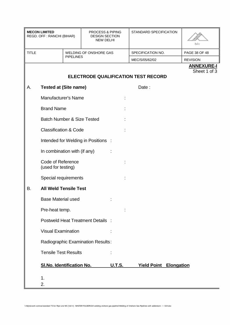
\\Akjha\work contrac\standard TS for Pipe Line WC (Vol-II) MASTER FOLDER\02A welding onshore gas pipeline\Welding of Onshore Gas Pipelines with addendum - I 02A.doc
MECON LIMITEDREGD. OFF : RANCHI (BIHAR)
PROCESS & PIPINGDESIGN SECTION
NEW DELHI
STANDARD SPECIFICATION
TITLE SPECIFICATION NO. PAGE 38 OF 48WELDING OF ONSHORE GASPIPELINES
MEC/S/05/62/02 REVISION
ANNEXURE-ISheet 1 of 3
ELECTRODE QUALIFICATION TEST RECORD
A. Tested at (Site name) Date :
Manufacturer's Name :
Brand Name :
Batch Number & Size Tested :
Classification & Code :
Intended for Welding in Positions :
In combination with (if any) :
Code of Reference :(used for testing)
Special requirements :
B. All Weld Tensile Test
Base Material used :
Pre-heat temp. :
Postweld Heat Treatment Details :
Visual Examination :
Radiographic Examination Results:
Tensile Test Results :
Sl.No. Identification No. U.T.S. Yield Point Elongation
1.2.
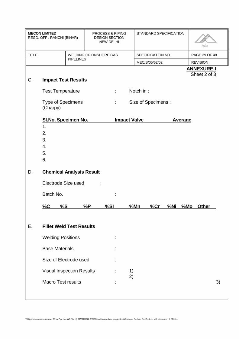
\\Akjha\work contrac\standard TS for Pipe Line WC (Vol-II) MASTER FOLDER\02A welding onshore gas pipeline\Welding of Onshore Gas Pipelines with addendum - I 02A.doc
MECON LIMITEDREGD. OFF : RANCHI (BIHAR)
PROCESS & PIPINGDESIGN SECTION
NEW DELHI
STANDARD SPECIFICATION
TITLE SPECIFICATION NO. PAGE 39 OF 48WELDING OF ONSHORE GASPIPELINES
MEC/S/05/62/02 REVISION
ANNEXURE-ISheet 2 of 3
C. Impact Test Results
Test Temperature : Notch in :
Type of Specimens : Size of Specimens :(Charpy)
Sl.No. Specimen No. Impact Valve Average1.2.3.4.5.6.
D. Chemical Analysis Result
Electrode Size used :
Batch No. :
%C %S %P %SI %Mn %Cr %Ni %Mo Other
E. Fillet Weld Test Results
Welding Positions :
Base Materials :
Size of Electrode used :
Visual Inspection Results : 1)2)
Macro Test results : 3)
\\Akjha\work contrac\standard TS for Pipe Line WC (Vol-II) MASTER FOLDER\02A welding onshore gas pipeline\Welding of Onshore Gas Pipelines with addendum - I 02A.doc
MECON LIMITEDREGD. OFF : RANCHI (BIHAR)
PROCESS & PIPINGDESIGN SECTION
NEW DELHI
STANDARD SPECIFICATION
TITLE SPECIFICATION NO. PAGE 40 OF 48WELDING OF ONSHORE GASPIPELINES
MEC/S/05/62/02 REVISION
ANNEXURE-ISheet 3 of 3
Fracture Test Results :
Remarks :
F. Other Test Results
1. Transverse Tensile Test :
In combination with :
Base Material used :
Position of Welding :
Preheat Temperature :
Post Weld Heat Treatment :
Radiography :
Identification No. U.T.S. Fracture in Remarks
2. Guided Bend Test
Position ID No. Root, Face or Side Bend Remarks1.2.3.4.5.
Any other Tests :
Conclusion :
\\Akjha\work contrac\standard TS for Pipe Line WC (Vol-II) MASTER FOLDER\02A welding onshore gas pipeline\Welding of Onshore Gas Pipelines with addendum - I 02A.doc
MECON LIMITEDREGD. OFF : RANCHI (BIHAR)
PROCESS & PIPINGDESIGN SECTION
NEW DELHI
STANDARD SPECIFICATION
TITLE SPECIFICATION NO. PAGE 41 OF 48WELDING OF ONSHORE GASPIPELINES
MEC/S/05/62/02 REVISION
ANNEXURE-IISheet 1 of 2
STRESS RELIEF HEAT TREATMENT PROCEDURE SPECIFICATION
Name of the Heat-Treater :
Name of the Project : Specification Reference No.:
1. General Details
Name of the Equipment :
Name of the Assembly/ Part :
Assembly/ Part Drawing No. :
Material :
2. Furnace Details
Type of Heating : Gas/ Oil/ Elec. Res./ Induction
Type of Heating : (Tick mark)
Capacity (Size) :
Maximum Temp.(°C) :
Method of Temp. :Measurement
Atmosphere Control :
3. Heat Treatment Cycle Details
Changing Temp. °C :
Rate of Heating, °C/ Hr. :
\\Akjha\work contrac\standard TS for Pipe Line WC (Vol-II) MASTER FOLDER\02A welding onshore gas pipeline\Welding of Onshore Gas Pipelines with addendum - I 02A.doc
MECON LIMITEDREGD. OFF : RANCHI (BIHAR)
PROCESS & PIPINGDESIGN SECTION
NEW DELHI
STANDARD SPECIFICATION
TITLE SPECIFICATION NO. PAGE 42 OF 48WELDING OF ONSHORE GASPIPELINES
MEC/S/05/62/02 REVISION
ANNEXURE-IISheet 2 of 2
Soaking Temp. °C :
Soaking Time, Hrs. :
Rate of Cooling, °C/ Hr. :
Mode of Cooling :
4. Other Details, if any.
Notes :The following documents shall be furnished alongwith the specifications :i. Material Test Certificatesii. Assembly/ Part Drawing.
\\Akjha\work contrac\standard TS for Pipe Line WC (Vol-II) MASTER FOLDER\02A welding onshore gas pipeline\Welding of Onshore Gas Pipelines with addendum - I 02A.doc
MECON LIMITEDREGD. OFF : RANCHI (BIHAR)
PROCESS & PIPINGDESIGN SECTION
NEW DELHI
STANDARD SPECIFICATION
TITLE SPECIFICATION NO. PAGE 43 OF 48WELDING OF ONSHORE GASPIPELINES
MEC/S/05/62/02 REVISION
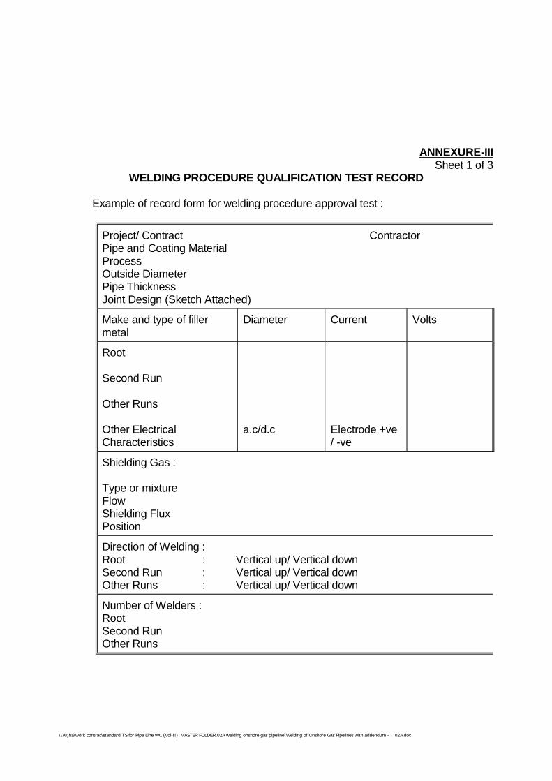
\\Akjha\work contrac\standard TS for Pipe Line WC (Vol-II) MASTER FOLDER\02A welding onshore gas pipeline\Welding of Onshore Gas Pipelines with addendum - I 02A.doc
ANNEXURE-IIISheet 1 of 3
WELDING PROCEDURE QUALIFICATION TEST RECORD
Example of record form for welding procedure approval test :
Project/ Contract ContractorPipe and Coating MaterialProcessOutside DiameterPipe ThicknessJoint Design (Sketch Attached)
Make and type of fillermetal
Diameter Current Volts
Root
Second Run
Other Runs
Other ElectricalCharacteristics
a.c/d.c Electrode +ve/ -ve
Shielding Gas :
Type or mixtureFlowShielding FluxPosition
Direction of Welding :Root : Vertical up/ Vertical downSecond Run : Vertical up/ Vertical downOther Runs : Vertical up/ Vertical down
Number of Welders :RootSecond RunOther Runs
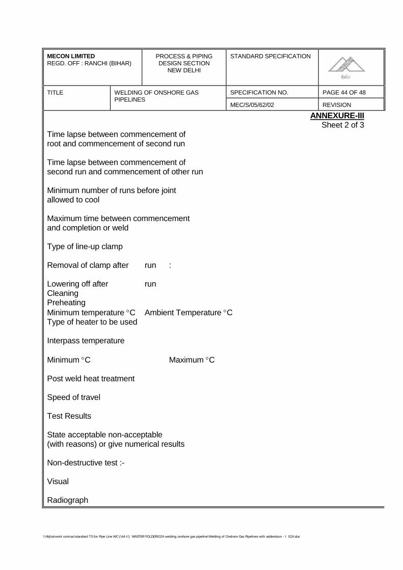
\\Akjha\work contrac\standard TS for Pipe Line WC (Vol-II) MASTER FOLDER\02A welding onshore gas pipeline\Welding of Onshore Gas Pipelines with addendum - I 02A.doc
MECON LIMITEDREGD. OFF : RANCHI (BIHAR)
PROCESS & PIPINGDESIGN SECTION
NEW DELHI
STANDARD SPECIFICATION
TITLE SPECIFICATION NO. PAGE 44 OF 48WELDING OF ONSHORE GASPIPELINES
MEC/S/05/62/02 REVISION
ANNEXURE-IIISheet 2 of 3
Time lapse between commencement ofroot and commencement of second run
Time lapse between commencement ofsecond run and commencement of other run
Minimum number of runs before jointallowed to cool
Maximum time between commencementand completion or weld
Type of line-up clamp
Removal of clamp after run :
Lowering off after runCleaningPreheatingMinimum temperature °C Ambient Temperature °CType of heater to be used
Interpass temperature
Minimum °C Maximum °C
Post weld heat treatment
Speed of travel
Test Results
State acceptable non-acceptable(with reasons) or give numerical results
Non-destructive test :-
Visual
Radiograph
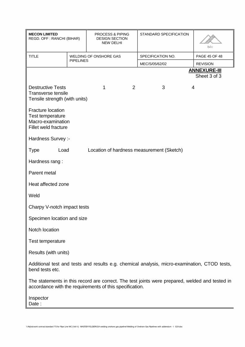
\\Akjha\work contrac\standard TS for Pipe Line WC (Vol-II) MASTER FOLDER\02A welding onshore gas pipeline\Welding of Onshore Gas Pipelines with addendum - I 02A.doc
MECON LIMITEDREGD. OFF : RANCHI (BIHAR)
PROCESS & PIPINGDESIGN SECTION
NEW DELHI
STANDARD SPECIFICATION
TITLE SPECIFICATION NO. PAGE 45 OF 48WELDING OF ONSHORE GASPIPELINES
MEC/S/05/62/02 REVISION
ANNEXURE-IIISheet 3 of 3
Destructive Tests 1 2 3 4Transverse tensileTensile strength (with units)
Fracture locationTest temperatureMacro-examinationFillet weld fracture
Hardness Survey :-
Type Load Location of hardness measurement (Sketch)
Hardness rang :
Parent metal
Heat affected zone
Weld
Charpy V-notch impact tests
Specimen location and size
Notch location
Test temperature
Results (with units)
Additional test and tests and results e.g. chemical analysis, micro-examination, CTOD tests,bend tests etc.
The statements in this record are correct. The test joints were prepared, welded and tested inaccordance with the requirements of this specification.
InspectorDate :
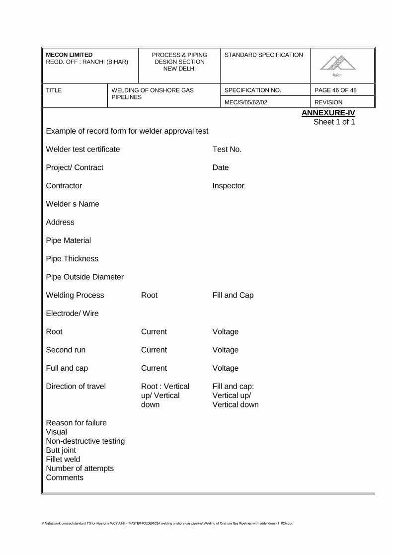
\\Akjha\work contrac\standard TS for Pipe Line WC (Vol-II) MASTER FOLDER\02A welding onshore gas pipeline\Welding of Onshore Gas Pipelines with addendum - I 02A.doc
MECON LIMITEDREGD. OFF : RANCHI (BIHAR)
PROCESS & PIPINGDESIGN SECTION
NEW DELHI
STANDARD SPECIFICATION
TITLE SPECIFICATION NO. PAGE 46 OF 48WELDING OF ONSHORE GASPIPELINES
MEC/S/05/62/02 REVISION
ANNEXURE-IVSheet 1 of 1
Example of record form for welder approval test
Welder test certificate Test No.
Project/ Contract Date
Contractor Inspector
Welder s Name
Address
Pipe Material
Pipe Thickness
Pipe Outside Diameter
Welding Process Root Fill and Cap
Electrode/ Wire
Root Current Voltage
Second run Current Voltage
Full and cap Current Voltage
Direction of travel Root : Vertical Fill and cap:up/ Vertical Vertical up/down Vertical down
Reason for failureVisualNon-destructive testingButt jointFillet weldNumber of attemptsComments
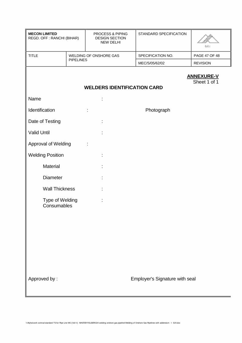
\\Akjha\work contrac\standard TS for Pipe Line WC (Vol-II) MASTER FOLDER\02A welding onshore gas pipeline\Welding of Onshore Gas Pipelines with addendum - I 02A.doc
MECON LIMITEDREGD. OFF : RANCHI (BIHAR)
PROCESS & PIPINGDESIGN SECTION
NEW DELHI
STANDARD SPECIFICATION
TITLE SPECIFICATION NO. PAGE 47 OF 48WELDING OF ONSHORE GASPIPELINES
MEC/S/05/62/02 REVISION
ANNEXURE-VSheet 1 of 1
WELDERS IDENTIFICATION CARD
Name :
Identification : Photograph
Date of Testing :
Valid Until :
Approval of Welding :
Welding Position :
Material :
Diameter :
Wall Thickness :
Type of Welding :Consumables
Approved by : Employer's Signature with seal
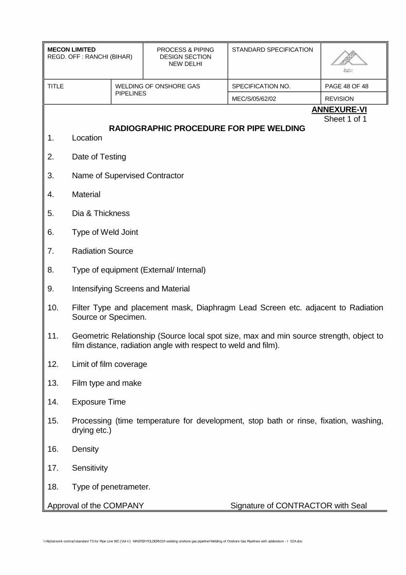
\\Akjha\work contrac\standard TS for Pipe Line WC (Vol-II) MASTER FOLDER\02A welding onshore gas pipeline\Welding of Onshore Gas Pipelines with addendum - I 02A.doc
MECON LIMITEDREGD. OFF : RANCHI (BIHAR)
PROCESS & PIPINGDESIGN SECTION
NEW DELHI
STANDARD SPECIFICATION
TITLE SPECIFICATION NO. PAGE 48 OF 48WELDING OF ONSHORE GASPIPELINES
MEC/S/05/62/02 REVISION
ANNEXURE-VISheet 1 of 1
RADIOGRAPHIC PROCEDURE FOR PIPE WELDING1. Location
2. Date of Testing
3. Name of Supervised Contractor
4. Material
5. Dia & Thickness
6. Type of Weld Joint
7. Radiation Source
8. Type of equipment (External/ Internal)
9. Intensifying Screens and Material
10. Filter Type and placement mask, Diaphragm Lead Screen etc. adjacent to RadiationSource or Specimen.
11. Geometric Relationship (Source local spot size, max and min source strength, object tofilm distance, radiation angle with respect to weld and film).
12. Limit of film coverage
13. Film type and make
14. Exposure Time
15. Processing (time temperature for development, stop bath or rinse, fixation, washing,drying etc.)
16. Density
17. Sensitivity
18. Type of penetrameter.
Approval of the COMPANY Signature of CONTRACTOR with Seal
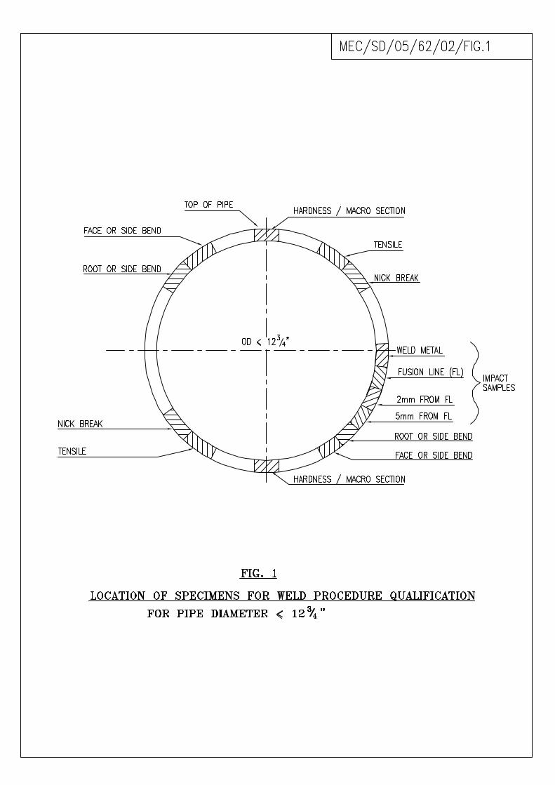
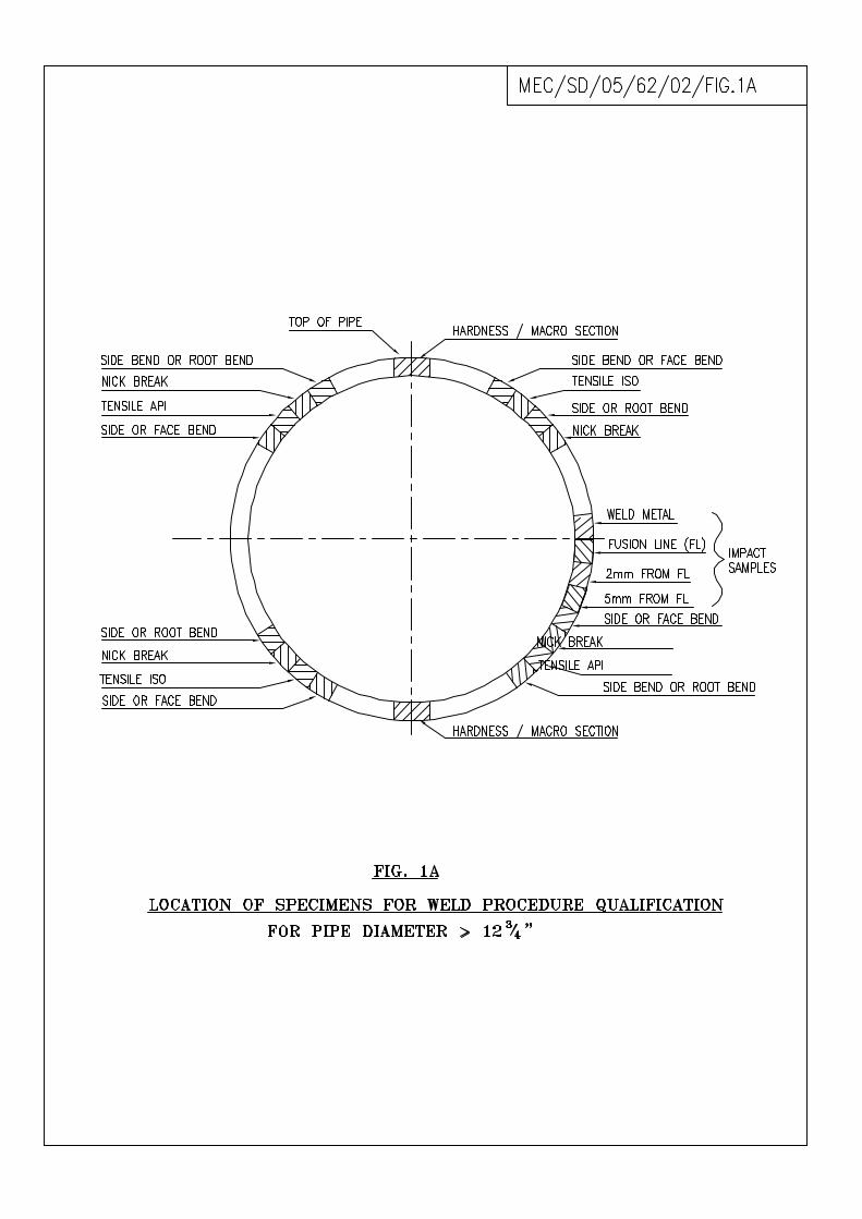
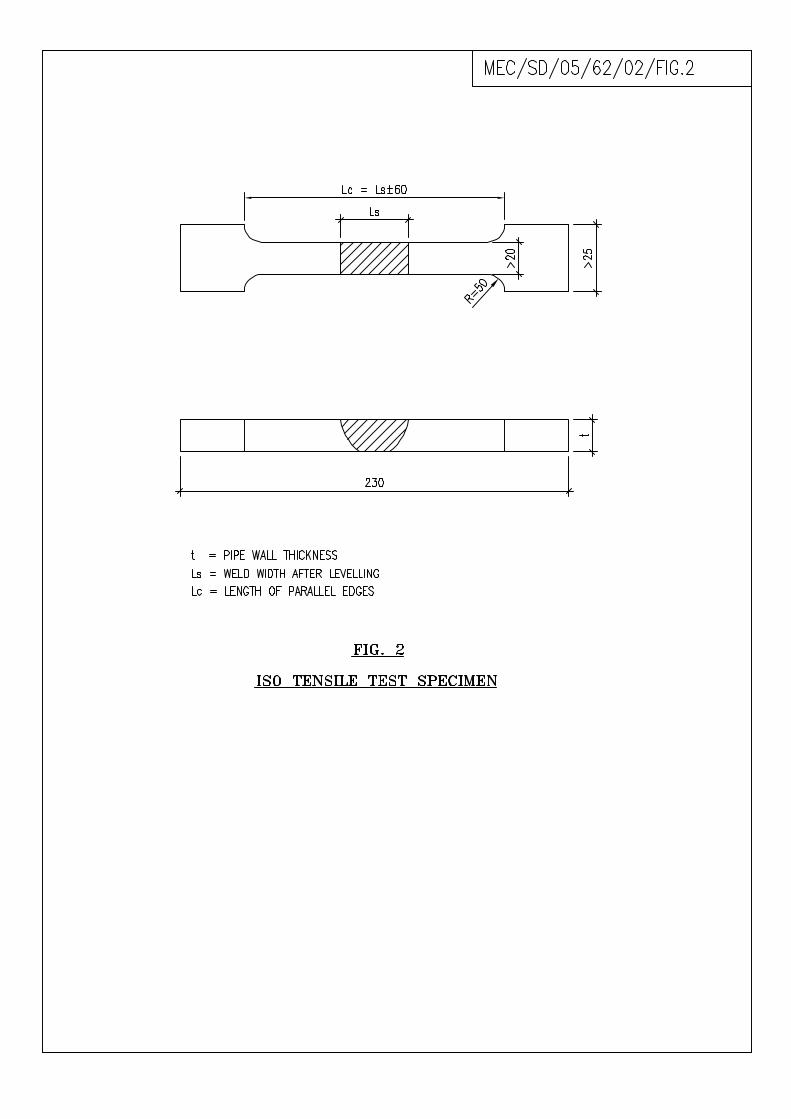
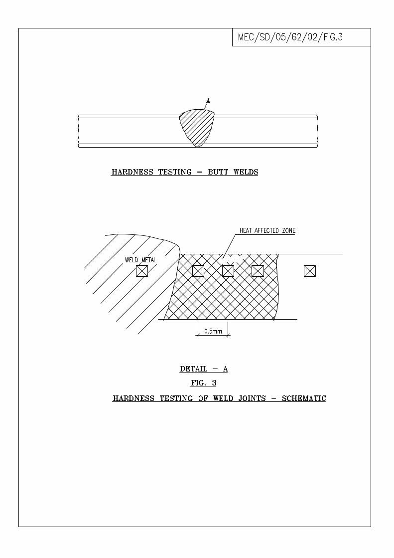
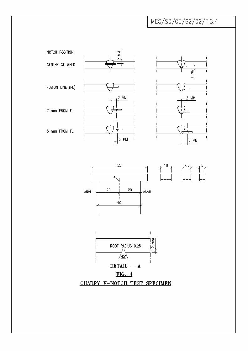
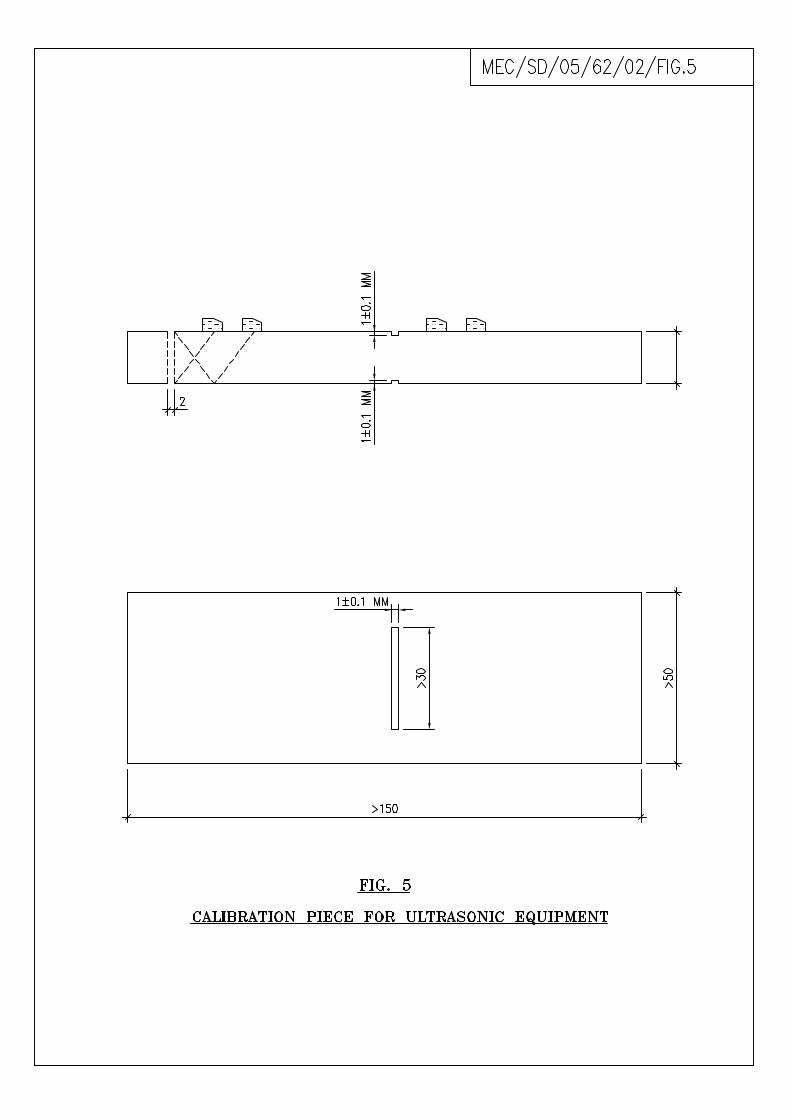
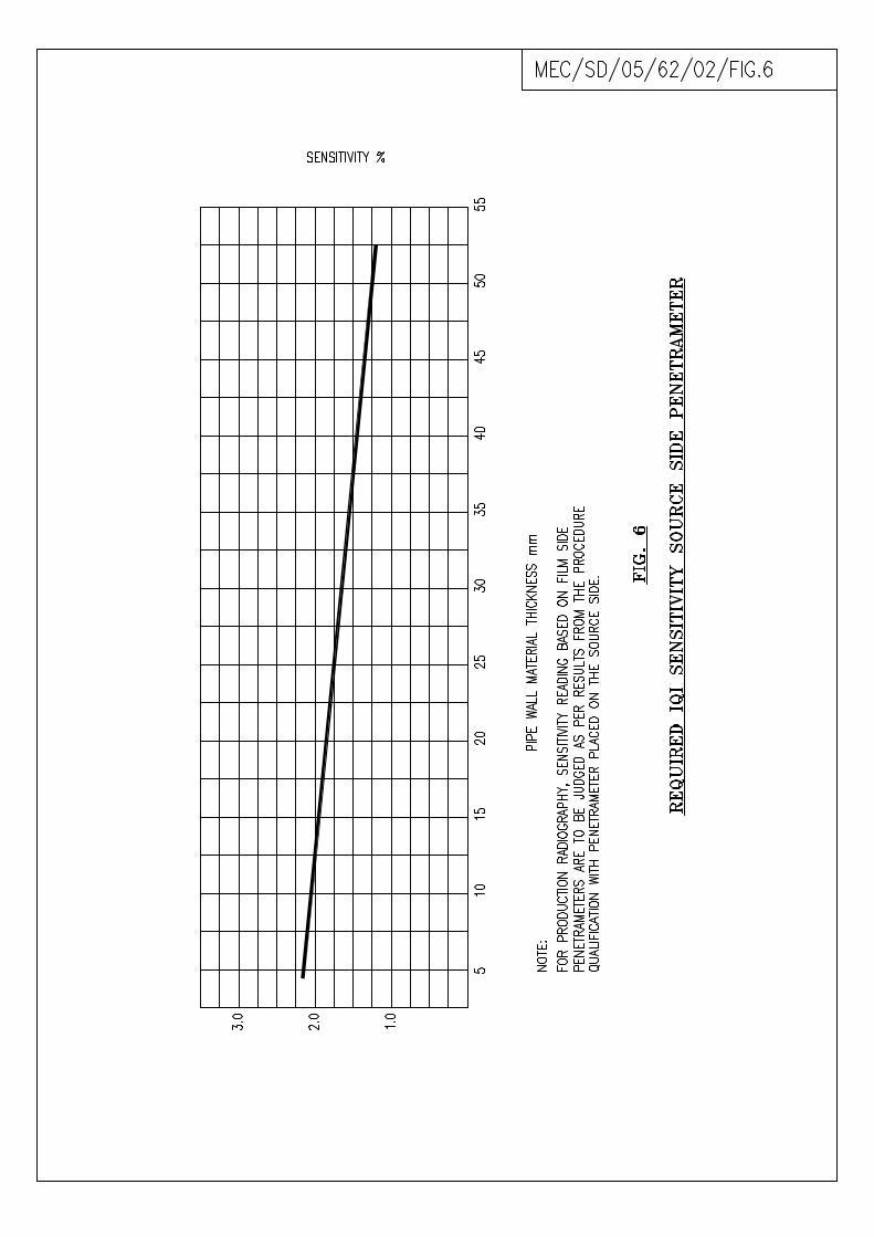
\\Akjha\work contrac\standard TS for Pipe Line WC (Vol-II) MASTER FOLDER\02A welding onshore gas pipeline\Welding of Onshore Gas Pipelines with addendum - I 02A.doc
ADDENDUM –1 TO SPECIFICATION NO. MEC/S/05/62/02A
1) Special Points
Followings points are to be considered strictly.
i) Acceptance criterion for welding procedure qualification and theirtesting welder qualification & their testing and non-destructiveexaminations of weld joints shall be as per API-1104 (Latest editions)
ii) Same criterion as mentioned above shall also be applicable to aboveground piping system.
SPECIFICATIONFOR
HYDROSTATIC TESTINGOF ONSHORE PIPELINE
SPECIFICATION NO. MEC/S/05/62/03
(PROCESS & PIPELINE DESIGN SECTION)MECON LIMITED
DELHI - 110 092
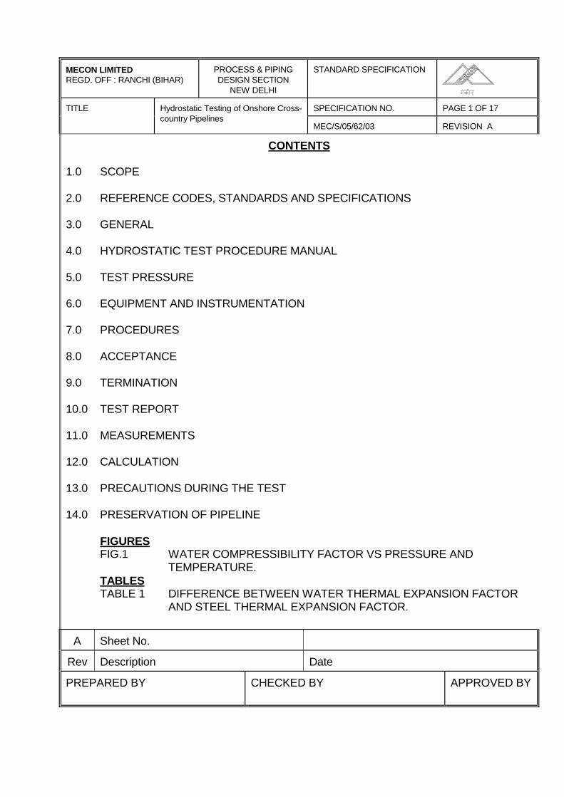
MECON LIMITEDREGD. OFF : RANCHI (BIHAR)
PROCESS & PIPINGDESIGN SECTION
NEW DELHI
STANDARD SPECIFICATION
TITLE SPECIFICATION NO. PAGE 1 OF 17Hydrostatic Testing of Onshore Cross-country Pipelines
MEC/S/05/62/03 REVISION A
CONTENTS
1.0 SCOPE
2.0 REFERENCE CODES, STANDARDS AND SPECIFICATIONS
3.0 GENERAL
4.0 HYDROSTATIC TEST PROCEDURE MANUAL
5.0 TEST PRESSURE
6.0 EQUIPMENT AND INSTRUMENTATION
7.0 PROCEDURES
8.0 ACCEPTANCE
9.0 TERMINATION
10.0 TEST REPORT
11.0 MEASUREMENTS
12.0 CALCULATION
13.0 PRECAUTIONS DURING THE TEST
14.0 PRESERVATION OF PIPELINE
FIGURESFIG.1 WATER COMPRESSIBILITY FACTOR VS PRESSURE AND
TEMPERATURE.TABLESTABLE 1 DIFFERENCE BETWEEN WATER THERMAL EXPANSION FACTOR
AND STEEL THERMAL EXPANSION FACTOR.
A Sheet No.
Rev Description Date
PREPARED BY CHECKED BY APPROVED BY
MECON LIMITEDREGD. OFF : RANCHI (BIHAR)
PROCESS & PIPINGDESIGN SECTION
NEW DELHI
STANDARD SPECIFICATION
TITLE SPECIFICATION NO. PAGE 2 OF 17Hydrostatic Testing of Onshore Cross-country Pipelines
MEC/S/05/62/03 REVISION A
1.0 SCOPE
1.1 This specification covers the minimum requirements of supply, works and operations tobe performed by CONTRACTOR for hydrostatic testing of cross-country steel pipelinestransporting hydrocarbons in liquid or gaseous phase under high pressure. Thisspecification does not cover the requirements of drying/precommissioning of the testedpipelines. This specification shall be read in conjunction with the conditions of allspecifications and documents included in the CONTRACT between COMPANY andCONTRACTOR.
2.0 REFERENCE CODES, STANDARDS AND SPECIFICATIONS
2.1 Reference has been made in this specification to the latest edition/ revision of thefollowing codes, standards and specifications.
a) ANSI B 31.8 Gas Transmission and Distribution Piping Systems.b) ANSI B 31.4 Liquid Petroleum Transportation Piping Systems.c) API RP 1110 Pressure Testing of Liquid Petroleum Pipelines.d) ASME Sec. VIII Div-1 Boiler & Pressure Vessel Code.
e) OISD 141 Design & construction requirements for cross-countryhdyrocarbon pipeline
2.2 In case of conflict between the requirements of this specification and that of the abovereferred coded, standards, and specifications, the requirements of this specificationsshall govern.
2.3 For the purpose of this specification the following definitions shall hold:
- the words 'shall' and 'Must' are mandatory;
- the words 'Should', 'May', and 'Will' are non-mandatory, advisory orrecommended.
3.0 GENERAL
3.1 Hydrostatic test shall be performed on the entire length of the pipeline. Hydrostatic testshall be performed in accordance with approved Hydrostatic Test Diagrams for eachtest section. The maximum length of each test section shall not exceed 25 kms.
MECON LIMITEDREGD. OFF : RANCHI (BIHAR)
PROCESS & PIPINGDESIGN SECTION
NEW DELHI
STANDARD SPECIFICATION
TITLE SPECIFICATION NO. PAGE 3 OF 17Hydrostatic Testing of Onshore Cross-country Pipelines
MEC/S/05/62/03 REVISION A
3.2 For pipeline sections which in COMPANY's opinion, once installed would require aninordinate amount of effort for repair in case of a leak, a provisional pre-test shall beconducted. However, after installation, such pretested sections shall be tested againalongwith the entire pipeline.
3.3 Hydrostatic test shall commence only after mechanical and civil works completion, i.e.,all welds have been accepted and the pipeline has been laid and backfilled accordingto the specifications. Hydrostatic test shall include those sections which have beenpreviously tested, viz. Rail/ road crossing, major water crossings including test on banksand in place after installation, and scraper traps at the terminals. CONTRACTOR shallperform all works required for hydrostatic testing after obtaining prior written approvalfrom the COMPANY.
3.4 The pipeline shall be tested in accordance with the requirements of the latest edition ofANSI B 31.8 or ANSI B 31.4, OISD 141 as applicable, and requirements laid down inthis specification.
4.0 HYDROSTATIC TEST PROCEDURE MANUAL
CONTRACTOR shall prepare for COMPANY's approval a hydrostatic test proceduremanual. The procedure shall strictly comply with the requirements of this specificationand shall be submitted to COMPANY for approval well in advance. The proceduremanual shall include all temporary materials & equipment, but not be limited to thefollowing items:
a) For the systems to be tested, a diagram indicating all fittings, vents, valves,temporary connections, relevant elevations and ratings. The diagram shall alsoindicate injection locations and intake and discharge lines.
b) Estimated amount of test water, water sources, including required concentrationof corrosion inhibitors and additives, procedure for inhibitor injection and controlof concentration.
c) Filling and flushing procedures, including a complete description of all proposedequipment and instruments (including spares), their location and set-up.
d) The type and sequence of pigs and the pig tracking systems for cleaning andremoval of air pockets. Pig inspection procedures, including procedure to befollowed in case the calliper pig indicates damage.
\\Akjha\work contrac\standard TS for Pipe Line WC (Vol-II) MASTER FOLDER\03A hydrostatic testing\Hydrostatic Testing of Onshore Pipeline 03A.doc
MECON LIMITEDREGD. OFF : RANCHI (BIHAR)
PROCESS & PIPINGDESIGN SECTION
NEW DELHI
STANDARD SPECIFICATION
TITLE SPECIFICATION NO. PAGE 4 OF 17Hydrostatic Testing of Onshore Cross-country Pipelines
MEC/S/05/62/03 REVISION A
e) Procedures for levelling and stabilization after filling and for pressurization and toallow for temperature stabilization.
f) Pressure testing procedure including a complete description of all proposedequipment and instruments (including spares), their location and set-up, andproposed system for observation and recording of data during the pressure test.
g) Procedure for detection and location of leaks.
h) Procedure for dewatering the pipeline section(s) after testing, including acomplete description of all proposed equipment and instruments, (includingspares), their location and set-up, the type and sequence of pigs and the pigtracking system along with the pig specifications.
i) Forms for recording the test data.
5.0 TEST DURATION AND PRESSURE
5.1 The duration of hydrostatic test shall be a minimum of 24 hours after stabilization andthe test pressure shall be as indicated in the approved hydrostatic test diagram.
5.2 Unless specified otherwise in the CONTRACT, the maximum base pressure shall notbe higher than the one resulting in a hoop stress corresponding to 90% of SMYS ofpipe material based on the minimum wall thickness in the test section and minimumtest pressure shall not be lower than the one resulting in a hoop stress correspondingto 85% of SMYS of pipe material based on the minimum wall thickness in the testsection.
6.0 EQUIPMENT AND INSTRUMENTATION
The CONTRACTOR shall furnish all necessary equipment for performing the work asstated in cleaning, flushing, filling, levelling, stabilizing, testing and dewateringprocedures. This shall include the following :
a) Pigs for filling , cleaning and gauging including
- Cleaning pigs with spring loaded steel wire brushes except for internal coatedpipes. In this case pigs to be provided with nylon / polyurethane brushes.
- Four cup batching pigs
\\Akjha\work contrac\standard TS for Pipe Line WC (Vol-II) MASTER FOLDER\03A hydrostatic testing\Hydrostatic Testing of Onshore Pipeline 03A.doc
MECON LIMITEDREGD. OFF : RANCHI (BIHAR)
PROCESS & PIPINGDESIGN SECTION
NEW DELHI
STANDARD SPECIFICATION
TITLE SPECIFICATION NO. PAGE 5 OF 17Hydrostatic Testing of Onshore Cross-country Pipelines
MEC/S/05/62/03 REVISION A
- Calliper pigs with gauge plate diameter equal to 95% of the heavy wallpipe in the pipe sections. Gauging pig fitted with gauge plate.
The CONTRACTOR shall provide sufficient number of pigs including spares.
b) Fill pumps : The CONTRACTOR shall determine the type and number of fill pumps in order to guarantee the following :Differential head 20% greater than the maximum required.Flow rate : 400m3 min. ; 1000m3 max.If a single pump is used, a standby unit must be available.
c) Variable speed positive displacement pumps equipped with a stroke counter topressurise the line with a known stroke and capable of exceeding the maximumtest pressure by at least 20 bar.
d) Two positive displacement meters to measure the volume of water used for filling the line. These meters shall be provided with a callibration certificate notolder than one month.
e) Portable tanks of sufficient size to provide a continuous supply of water to thepump during pressurizing.
f) Bourdon pressure gauges of suitable pressure range and accuracy.
g) Dead weight testers with an accuracy of 0.01 bar measuring in increments of0.05 bar provided with a calibration certificate not older than one month.
h) Two 48 hours recording pressure gauges tested with charts and ink gaugestested with dead weight tester prior to use. These shall be installed atp the testheads.
i) Pressure recording charts.
j) Two temperature recorders for fill water.
k) Thermocouples for measuring the pipe wall temperature.
l) Two laboratory thermometers 0°C to 60°C range, accuracy ± 0.1 degree to beused in thermowells.
MECON LIMITEDREGD. OFF : RANCHI (BIHAR)
PROCESS & PIPINGDESIGN SECTION
STANDARD SPECIFICATION
c:\fateh\standard\stad-eqp.wp
NEW DELHI
TITLE SPECIFICATION NO. PAGE 6 OF 17Hydrostatic Testing of Onshore Cross-country Pipelines
MEC/S/05/62/03 REVISION A m) Means to measure the volume of water necessary to drop the line pressure by
0.5 bar (container on scales or graduated cylinder).
n) Injection facilities to inject additives into the test medium in the requiredproportions.
o) Communication equipment suitable for a continuous connection between thebeginning and the end of the test section and with the inspection team along theline, in accordance with the requirements of local Authorities.
p) The temporary scraper traps shall be installed according to the testing sectionsfixed in the test procedure manual. Proper piping and valuing arrangementsshall be available to allow launching and receiving of each pig independently.
The test heads shall be sized in conformity with ASME specification Section VIII,Division 2 with particular reference to Appendices 4 and 5.
q) Thermocouples for assuring the temperature of the pipe wall shall be installedon the pipeline to be tested:
- 1 thermocouple at about 500m distance from the pumping head.- 1 thermocouple every 2500m of the pipe the spacing may be increased to
maximum 5000m depending on the terrain and nature of sub-soil along thealignment of section.
- 1 thermocouple at about 500m distance from the terminal head.
The spacing may be increased to maximum 5000 metre depending on the terrain andnature of sub soil along the alignment of test section.
Thermocouples shall be attached on the external surface of the pipe after removal ofexternal coating and shall be adequately protected and COMPANY's coatinginstructions shall be followed.
7.0 PROCEDURES
7.1 Equipment and/or parts which need not or must not be subjected to the test pressures,must be disconnected or separated from the pipeline to be tested.
7.2 If the difference of minimum and maximum atmosphere temperature should causethermal instability on the pipe section directly exposed to atmospheric condition, thescraper traps and above ground pipeline shall be properly protected.
c:\fateh\standard\stad-eqp.wp
MECON LIMITEDREGD. OFF : RANCHI (BIHAR)
PROCESS & PIPINGDESIGN SECTION
NEW DELHI
STANDARD SPECIFICATION
TITLE SPECIFICATION NO. PAGE 7 OF 17Hydrostatic Testing of Onshore Cross-country Pipelines
MEC/S/05/62/03 REVISION A The pipeline test shall exclude long segments of line exposed to atmosphericconditions, viz. Aerial lengths on piers, suspension bridges, etc., which shall be testedseparately.
7.3 The test medium shall be soft non-aggressive water furnished by the CONTRACTOR.The water to be used shall be filtered, shall not be contaminated, and free from sand orsilt. CONTRACTOR shall submit laboratory test reports of water used for testing. Thepossible use of sea water shall be subject to its degree of cleanliness, the possibility ofobtaining a pre determined salinity neutralization and the use of corrosion inhibitors,this at the sole discretion of COMPANY. CONTRACTOR shall provide COMPANYapproved corrosion inhibitors, oxygen scavengers and bactericides to be added to thetest water. The CONTRACTOR shall furnish and install all temporary piping which maybe necessary to connect from source of water to its pumps and manifolds/ tankage.
7.4 Before filling operation the CONTRACTOR shall clean the pipeline by air driven pigsprovided with spring loaded bushes and chisels to remove all mill scale rust/ sand fromthe inside of pipe section. For this purpose temporary headers for air cleaning shall beattached to the pipeline. The number of pig runs is depending upon the cleaning resultsand shall be determined by the COMPANY at site.
7.5 “After cleaning the pipeline by using air and acceptance by Company, gauging shall becarried out by using gauging pig. The gauge plate diameter shall be equal to 95% ofinside diameter of the heaviest wall pipe in the test section. While computing the ID ofheaviest wall pipe, pipe manufacturing tolerance shall not be considered. A 10mmthick aluminium plate shall be used for making gauge plate.After receipt of gauging pig at the other end, the gauge plate shall be inspected in thepresence of Company representative. A deformed, bent or severally nicked plate ordamaged pig shall be evidence of gauging pig run failure and the same is notacceptable to company. In such cases the Contractor shall repair and rectify the lineand repeat the gauging pig run to the satisfaction and approval of the CompanyRepresentative. Any obstruction and/ or faults such as dents, buckles, flat spots, etc.analysed and noted during gauging pig run shall be located and any necessary repairwork shall be performed to rectify the same to the satisfaction of the Company. Awritten approval shall be obtained from Company regarding successful completion ofgauging pig run.After acceptance of gauging operation, air header shall be cut and removed. Pre-tested test headers loaded with three numbers of four cup batching pig shall be weldedto test Section. Un-inhibited water equal to 10% of the volume of test section shall beintroduced in front of the first pig. The first pig shall be launched by introducing about1.5 km un-inhibited water. Then the second pig shall be launched by pumping theinhibited water till the second pig is received at the other end. The thermal stablisationand pressurisation can now the started”.
c:\fateh\standard\stad-eqp.wp
MECON LIMITEDREGD. OFF : RANCHI (BIHAR)
PROCESS & PIPINGDESIGN SECTION
NEW DELHI
STANDARD SPECIFICATION
TITLE SPECIFICATION NO. PAGE 8 OF 17Hydrostatic Testing of Onshore Cross-country Pipelines
MEC/S/05/62/03 REVISION A 7.6 Thermal Stabilization
After a check has been made to confirm if the pressure has attained at least 1 bar (g)on the highest section, thermal stabilization can be started.
Thermal equilibrium between the pipeline and environment shall be checked throughthe thermocouples installed on the pipeline.
Temperature readings shall be made at 4 hours-intervals. Thermal stabilization shall beconsidered to have been achieved when a difference not higher than 1°C is attainedbetween the average values of the last two readings. Thermal stabilization completionshall be approved by COMPANY.
7.7 Pressurisation
Pressurisation shall be performed in the presence of COMPANY at moderate andconstant rate not exceeding 2 bars/min. One pressure recording gauge shall beinstalled in parallel with the dead weight tester. Volume required to reach the testpressure shall be recorded periodically throughout the pressurization as follows:
- each 5 bar increments up to 80% of test pressure as recorded by the deadweight tester;
- each 2 bar increment between 80% to 90% of test pressure as recorded by thedead weight tester;
- each 0.2 bar increment between 90% of test pressure to full test pressure asrecorded by the dead weight tester.
The pressurizing shall be cycled according to the following sequence:a) Pressurize to 50% of test pressure, hold pressure for 1 hour.b) Drop pressure to static head of test section at test head.c) Pressurize to 75% of test pressure, hold pressure for 1 hour.d) Drop pressure to static head of test section at the test head.e) Pressurize to test pressure.
During the pressurization to each test pressure, two tests shall be carried out for thecalculation of air volume in the pipeline under test.
In case, during the hold pressure periods indicated above, a decrease in pressure isobserved, the operations shall not be repeated more than twice, after which the lineshall not be considered capable of test, until the CONTRACTOR has isolated andeliminated the cause for the lack of water tightness.
c:\fateh\standard\stad-eqp.wp
MECON LIMITEDREGD. OFF : RANCHI (BIHAR)
PROCESS & PIPINGDESIGN SECTION
NEW DELHI
STANDARD SPECIFICATION
TITLE SPECIFICATION NO. PAGE 9 OF 17Hydrostatic Testing of Onshore Cross-country Pipelines
MEC/S/05/62/03 REVISION A 7.8 Air Volume Calculation
In order to check the presence of air in the pipeline, two separate consecutive pressurelowering of 0.5 bar shall be carried out.
For calculation of air in the pipeline the second pressure lowering shall be used, andthe relevant drained water shall be accurately measured (V1). This amount measuredshall be compared to the theoretical amount (Vp) corresponding to the pressurelowering that has been carried out, by using the procedure outlined in clause 12.1 ofthis specification.
If no air is present in the length under test:
V1--- = 1Vp
In order that the above ratio is acceptable, it shall not differ from 1 by more than 6%(i.e. 1.06).If the air found in the pipeline is within the above established tolerance, then thepressurizing can continue. If the ratio V1 / Vp exceeds 1.06, the hydrostatic testingcannot go on and additional pig passages shall be performed to remove the airpockets.
The test shall be repeated as per the above procedure until above estimatedtolerances are satisfied. The pressurizing can then continue, to reach the value of testpressure.
7.9 Testing
After the section has been pressurized and the air volume test has given acceptableresults the test pressure shall be held for a minimum of 24 hours after stabilization.After temperature and pressure has stabilized, the injection pump shall bedisconnected and all connections at the test heads shall be checked for leakage. Thepressure recorders shall then be started with the charts in a real time orientation forcontinuous recording throughout the test.
During the testing period the following measurements shall be recorded :
- every one hour pressure measurements form dead weight testers.- every two hours the ambient temperature and the pipe temperature at the
thermocouples.All data shall be recorded on appropriate forms attached to the hydrostatic test
procedure manual. Care shall be taken that the maximum test pressures are not exceeded.
c:\fateh\standard\stad-eqp.wp
MECON LIMITEDREGD. OFF : RANCHI (BIHAR)
PROCESS & PIPINGDESIGN SECTION
NEW DELHI
STANDARD SPECIFICATION
TITLE SPECIFICATION NO. PAGE 10 OF 17Hydrostatic Testing of Onshore Cross-country Pipelines
MEC/S/05/62/03 REVISION A
Bleed-off water shall be accurately measured and recorded.
8.0 ACCEPTANCE
8.1 The hydrostatic test shall be considered as passed if pressure has kept a constantvalue throughout the test duration, except for change due to temperature effects. Suchchange shall be evaluated as described under clause 12.2 of this specification.
The pressure change value as a function of temperature change shall be algebraicallyadded to the pressure value as read on the meters. The pressure value thus adjustedshall be compared with the initial value and the test shall be considered as acceptableif the difference is less than or equal to 0.3 bar. In case of doubt the testing period shallbe extended by 24 hours.
8.2 If test section fails to maintain the specified test pressure after isolation,CONTRACTOR shall determine by search the location of leakage or failure. All leaksand failures within the pipe wall or weld seam shall be repaired by replacement of entirejoint or joints in which leakage or failure occurs. In circumferential welds the method ofrepair shall be determined by the COMPANY. CONTRACTOR shall comply withinstructions of the COMPANY whether to replace a section of the line pipe thatincludes the line leak or whether to repair the circumferential weld. This repair shouldhowever meet the requirements of 'Specification for Welding Pipelines and RelatedFacilities'. Where failure occur in pipeline field bends, bends shall be replaced withsame degree of bends. After completion of repairs, the hydrostatic test shall berepeated in full, as per this specification.
8.3 The cost of repairs or replacements, followed by refilling and repressurizing the line,due to poor workmanship, shall be borne by the CONTRACTOR. In the event of leaksor failures resulting form faulty COMPANY furnished materials, CONTRACTOR shallbe reimbursed for furnishing all labour, equipment, materials, except those materialsfurnished by the COMPANY, and transportation necessary to repair and repressurizethe section of the pipeline to the pressure at the time of recognition of leak or linefailure. CONTRACTOR shall be entitled for compensation as per the provisions of theCONTRACT. All work of reinstalling line pipe, to replace pipe failures shall be done inaccordance with the relevant specification included in the CONTRACT.
c:\fateh\standard\stad-eqp.wp
MECON LIMITEDREGD. OFF : RANCHI (BIHAR)
PROCESS & PIPINGDESIGN SECTION
NEW DELHI
STANDARD SPECIFICATION
TITLE SPECIFICATION NO. PAGE 11 OF 17Hydrostatic Testing of Onshore Cross-country Pipelines
MEC/S/05/62/03 REVISION A
8.4 CONTRACTOR shall haul and stockpile all damaged and defective pipes to storagelocations designated by the COMPANY. All cracks and splice resulting from failuresshall be coated with an application of grease to preserve the characteristics of failuresfrom corrosion. Joint of failed pipes shall be marked with paint, with a tag indicatingfailure details, date and location of failure and pressure at which failure occurred.
9.0 TERMINATION
After the positive results of testing and collection of all data the test shall be terminatedupon written approval given by the COMPANY.
9.1 CONTRACTOR shall dewater the tested line as per the following requirement after testacceptance.
The dewatering shall be carried out by using four cup pigs and foam pigs driven bycompressed air. The detailed dewatering procedure shall be developed by theCONTRACTOR in such a way as to provide adequate control of pigs duringdewatering. Pigs and equipment required for dewatering the line shall be furnished byCONTRACTOR and shall be approved in advance by the COMPANY. Four cup pigsshall first be passed through the line to displace the water. Foam pigs shall then bepassed in order to complete the line dewatering. CONTRACTOR shall use a number offoam pigs, each in different colors/ numbered for this purpose. The line shall beconsidered dewatered when a negligible amount of water is flushed out by the lastfoam pig and approval is given by the COMPANY.
9.2 During dewatering, care shall be taken to properly dispose the discharging water inorder to avoid pollution, damages to fields under cultivation and/or existing structuresand interference with the traffic. Before start of dewatering and disposal of hydrotestwater, a procedure for treatment of inhibited water to prevent pollution shall besubmitted by contractor to owner/ consultant for review and approval.
9.3 Upon completion of the testing and dewatering operation, any provisional traps for pigsand all other temporary installation relating to the test shall be removed. Subsequentlythe individual sections of the line already tested shall be joined in accordance with therequirements of relevant specifications issued for the purpose.
10.0 TEST REPORT
A complete report signed by CONTRACTOR and the COMPANY shall be submittedupon completion of the hydrostatic test for each test section.
c:\fateh\standard\stad-eqp.wp
MECON LIMITEDREGD. OFF : RANCHI (BIHAR)
PROCESS & PIPINGDESIGN SECTION
NEW DELHI
STANDARD SPECIFICATION
TITLE SPECIFICATION NO. PAGE 12 OF 17Hydrostatic Testing of Onshore Cross-country Pipelines
MEC/S/05/62/03 REVISION A
This report shall contain as a minimum:
- the cleaning, flushing, filling and testing procedures used;
- schematic layout of cleaning, filling and testing facilities;
- instruments calibration certificates;
- a profile of the pipeline that shows the test sites, all instrument and injectionconnections;
- pipe filling logs and records;
- additive specification, required concentration and additive injection records;
- pig specifications;
- pig inspection records including photographs of the damages;
- records of gauging pig survey and photographs;
- pressurization and stabilization records;
- pressure and temperature recording charts with appropriate informationinscribed thereon;
- temperature data along the pipeline;
- dead weight tester logs and recording;
- air volume calculations;
- pressure change due to temperature change calculations;
- environmental data;
- depressurization logs and records;
- dewatering procedure and schematic layout of relevant facilities;

c:\fateh\standard\stad-eqp.wp
MECON LIMITEDREGD. OFF : RANCHI (BIHAR)
PROCESS & PIPINGDESIGN SECTION
NEW DELHI
STANDARD SPECIFICATION
TITLE SPECIFICATION NO. PAGE 13 OF 17Hydrostatic Testing of Onshore Cross-country Pipelines
MEC/S/05/62/03 REVISION A
- dewatering logs and records;
- records and photograph of all leaks.
11.0 MEASUREMENTS
11.1 Water Amount Measurement
The water volume added to the section to be tested shall be measured during the fillingstage through a positive displacement meter (a turbine meter may also be used). In thecalculation, as per clause 12.1 of this specification, use shall be made of thegeometrical volume of the section in question.
11.2 Pressure Measurement
Pressure shall be measured with a dead weight tester with an accuracy of 0.01 bar thatshall permit readings of at least 0.05 bar.
During the test the pressure shall be recorded by means of a pressure recorderfeaturing the following specifications:
Accuracy : ± 0.1% of the full-scale value
Recording : continuous on tape or disk, graph width 100mm
Feed : 20mm/h for tape diagrams, 7.5°/h for disk diagrams
Recording : to be such as to record pressure between 50% and 90% of thediagram width.
The pressure recorder shall be checked by means of dead weight tester at thebeginning, during and at the end of the hydrostatic test.
A pressure gauge tested with dead weight tester shall be connected in parallel to thedead weight tester at the test head.
11.3 Temperature Measurements
Water temperature shall be taken at every 2 hours through the thermocouple that havebeen installed on the pipe wall along the section under test on the pipe wall.
c:\fateh\standard\stad-eqp.wp
MECON LIMITEDREGD. OFF : RANCHI (BIHAR)
PROCESS & PIPINGDESIGN SECTION
NEW DELHI
STANDARD SPECIFICATION
TITLE SPECIFICATION NO. PAGE 14 OF 17Hydrostatic Testing of Onshore Cross-country Pipelines
MEC/S/05/62/03 REVISION A
Further the temperature measurement shall be taken :
- during the filling operation
- during the thermal stabilization stage
- during the hydrostatic test
The thermocouple’s sensitivity shall enable temperature readings with an accuracy of±0.2°C.
b) Water temperature shall also be measured on the pump delivery by means of arecording thermometer (temperature recorder) throughout the filling stage.
The recording thermometer shall have the following features :
Accuracy ± 1% of the scale range
Scale - 10° to + 40° C
Recording: Continuous on tape or disk, diagram within 100mm
Feed : 20mm/h for tape diagrams, 7.5°/h for disk diagrams.
c) Ground temperature shall be taken by measuring pipe temperature at thethermocouple prior to starting the filling operation.
d) Environmental temperature shall be recorded from the beginning ofpressurization to the end of the test by means of a recording thermometerfeaturing the following characteristics:
Accuracy ± 1% of the scale range
Scale - 0° to + 60° C
Recording: Continuous on tape or disk, diagram width 100mm
Feed : 20mm/h for tape diagrams, 7.5°/h for disk diagrams.
c:\fateh\standard\stad-eqp.wp
MECON LIMITEDREGD. OFF : RANCHI (BIHAR)
PROCESS & PIPINGDESIGN SECTION
NEW DELHI
STANDARD SPECIFICATION
TITLE SPECIFICATION NO. PAGE 15 OF 17Hydrostatic Testing of Onshore Cross-country Pipelines
MEC/S/05/62/03 REVISION A
12.0 CALCULATIONS
12.1 The theoritical water amount that is necessary for filling the section to be tested shallbe obtained from the geometrical volume of the section considering the pipetolerances.
The theoretical water amount that is necessary for pressurizing the section shall becalculated by means of the following formula:
Vp = (0.884 r i/t +A) x 10-6 x Vt x ∆ P x K
Where:
Vp = computed water amount required to raise by P the pressure in the sectionto be tested (m3).
Vt = geometrical volume of the section (m3)
∆ P = Pressure rise (bar)
r i = nominal inner radius of the pipe (mm)
t = nominal pipe thickness(mm)
A = isothermal compressibility value for water at the pressurizationtemperature in the P range (bar-1) x 106.
(Refer water compressibility factor vs pressure and temperature chart). For temperature above 30°C the values may be extrapolated.
K = a dimensionless coefficient that is equal to a value of 1.02 forlongitudinally welded pipe.
12.2 The pressure change due to a water temperature change shall be calculated by thefollowing formula:
B ∆P = -------------------------- ∆T
0.884 r i/ t +A
c:\fateh\standard\stad-eqp.wp
MECON LIMITEDREGD. OFF : RANCHI (BIHAR)
PROCESS & PIPINGDESIGN SECTION
NEW DELHI
STANDARD SPECIFICATION
TITLE SPECIFICATION NO. PAGE 16 OF 17Hydrostatic Testing of Onshore Cross-country Pipelines
MEC/S/05/62/03 REVISION A
Where,
∆P = pressure change resulting from a temperature change (bar)
∆T algaebrical difference between water temperature at the beginning of the testand water temperature as measured at the end of the test (°C).
B = value of the difference between the thermal expansion of water at the pressureand temperature as measured at the end of the test and that of steel (°C-1) x 106
(Refer table – 1)
A = Isothermal compressibility value of water as estimated at the pressure andtemperature values obtained at the end of test (bar-1) x 106 (Refer Figure 1)
r i = nominal inner radius of the pipe (mm).
t = nominal thickness of pipe (mm).
13.0 PRECAUTIONS DURING THE TEST
In addition to all that has been expressly described in the procedures for carrying outthe tests, the following additional requirements shall be complied with:
13.1 Provision shall be made for the installation of no-admittance signs to unauthorizedpersonnel from the roads to the R.O.W.
13.2 Signs stating "PIPE UNDER TEST-KEEP OFF" with local language translation shall beplaced where the pipeline is uncovered, and particularly where the provisional trapsand stations are located. Such areas shall be suitably fenced in such a way as toprevent access of unauthorized personnel. No unauthorized personnel shall be closerthan 40 m to the pipeline or equipment under test.
13.3 Provisional scraper traps shall be installed in compliance with methods and suitablelocations so that their rupture cannot cause any injuries to the personnel or thirdparties.
13.4 The test station shall be placed in such a location as to prevent it from being affectedby a catastrophic failure in the test head.
c:\fateh\standard\stad-eqp.wp
MECON LIMITEDREGD. OFF : RANCHI (BIHAR)
PROCESS & PIPINGDESIGN SECTION
NEW DELHI
STANDARD SPECIFICATION
TITLE SPECIFICATION NO. PAGE 17 OF 17Hydrostatic Testing of Onshore Cross-country Pipelines
MEC/S/05/62/03 REVISION A
13.5 Once dewatering is over, the sectionalizing valves and other valve assemblies testedpreviously, shall be installed at locations shown in the drawings and in accordance withthe procedures contained in the relevant specifications. All thermocouple installed inthe pipeline shall be removed and damaged corrosion coating shall be repaired usingCOMPANY approved materials and procedure.
14.0 PRESERVATION OF PIPELINE
When so stated in the CONTRACT, to preserve/conserve the pipeline for a specifiedduration, CONTRACTOR shall completely fill the pipeline with water, with sufficientquantity of corrosion inhibitors depending upon quality of water and the period ofconservation, at a pressure to be agreed upon with the COMPANY at a later stage.CONTRACTOR shall obtain necessary approval from the COMPANY of the procedureand the type and quantity of the inhibitors used before commencement of the works.
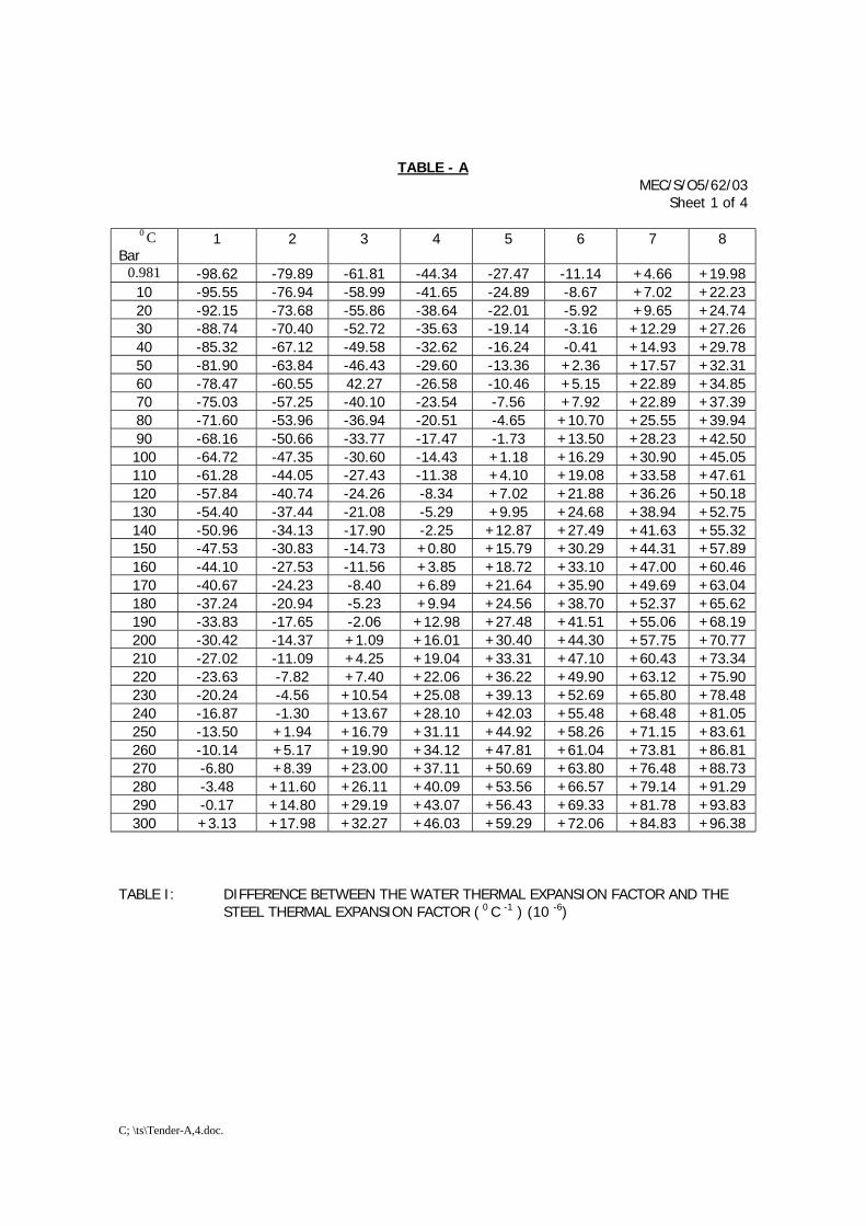
C; \ts\Tender-A,4.doc.
TABLE - A MEC/S/O5/62/03
Sheet 1 of 4
0 CBar
1 2 3 4 5 6 7 8
0.981 -98.62 -79.89 -61.81 -44.34 -27.47 -11.14 +4.66 +19.9810 -95.55 -76.94 -58.99 -41.65 -24.89 -8.67 +7.02 +22.2320 -92.15 -73.68 -55.86 -38.64 -22.01 -5.92 +9.65 +24.7430 -88.74 -70.40 -52.72 -35.63 -19.14 -3.16 +12.29 +27.2640 -85.32 -67.12 -49.58 -32.62 -16.24 -0.41 +14.93 +29.7850 -81.90 -63.84 -46.43 -29.60 -13.36 +2.36 +17.57 +32.3160 -78.47 -60.55 42.27 -26.58 -10.46 +5.15 +22.89 +34.8570 -75.03 -57.25 -40.10 -23.54 -7.56 +7.92 +22.89 +37.3980 -71.60 -53.96 -36.94 -20.51 -4.65 +10.70 +25.55 +39.9490 -68.16 -50.66 -33.77 -17.47 -1.73 +13.50 +28.23 +42.50100 -64.72 -47.35 -30.60 -14.43 +1.18 +16.29 +30.90 +45.05110 -61.28 -44.05 -27.43 -11.38 +4.10 +19.08 +33.58 +47.61120 -57.84 -40.74 -24.26 -8.34 +7.02 +21.88 +36.26 +50.18130 -54.40 -37.44 -21.08 -5.29 +9.95 +24.68 +38.94 +52.75140 -50.96 -34.13 -17.90 -2.25 +12.87 +27.49 +41.63 +55.32150 -47.53 -30.83 -14.73 +0.80 +15.79 +30.29 +44.31 +57.89160 -44.10 -27.53 -11.56 +3.85 +18.72 +33.10 +47.00 +60.46170 -40.67 -24.23 -8.40 +6.89 +21.64 +35.90 +49.69 +63.04180 -37.24 -20.94 -5.23 +9.94 +24.56 +38.70 +52.37 +65.62190 -33.83 -17.65 -2.06 +12.98 +27.48 +41.51 +55.06 +68.19200 -30.42 -14.37 +1.09 +16.01 +30.40 +44.30 +57.75 +70.77210 -27.02 -11.09 +4.25 +19.04 +33.31 +47.10 +60.43 +73.34220 -23.63 -7.82 +7.40 +22.06 +36.22 +49.90 +63.12 +75.90230 -20.24 -4.56 +10.54 +25.08 +39.13 +52.69 +65.80 +78.48240 -16.87 -1.30 +13.67 +28.10 +42.03 +55.48 +68.48 +81.05250 -13.50 +1.94 +16.79 +31.11 +44.92 +58.26 +71.15 +83.61260 -10.14 +5.17 +19.90 +34.12 +47.81 +61.04 +73.81 +86.81270 -6.80 +8.39 +23.00 +37.11 +50.69 +63.80 +76.48 +88.73280 -3.48 +11.60 +26.11 +40.09 +53.56 +66.57 +79.14 +91.29290 -0.17 +14.80 +29.19 +43.07 +56.43 +69.33 +81.78 +93.83300 +3.13 +17.98 +32.27 +46.03 +59.29 +72.06 +84.83 +96.38
TABLE I: DIFFERENCE BETWEEN THE WATER THERMAL EXPANSION FACTOR AND THESTEEL THERMAL EXPANSION FACTOR ( 0 C -1 ) (10 -6)
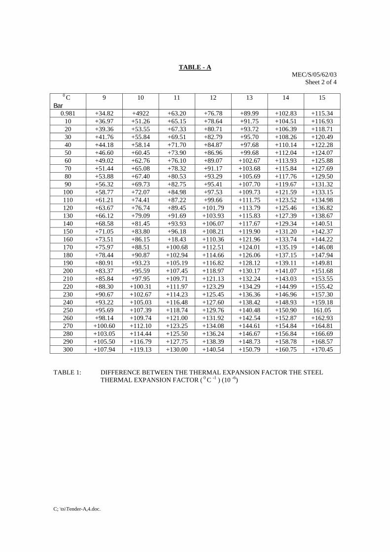
C; \ts\Tender-A,4.doc.
TABLE - AMEC/S/05/62/03
Sheet 2 of 4
0 CBar
9 10 11 12 13 14 15
0.981 +34.82 +4922 +63.20 +76.78 +89.99 +102.83 +115.3410 +36.97 +51.26 +65.15 +78.64 +91.75 +104.51 +116.9320 +39.36 +53.55 +67.33 +80.71 +93.72 +106.39 +118.7130 +41.76 +55.84 +69.51 +82.79 +95.70 +108.26 +120.4940 +44.18 +58.14 +71.70 +84.87 +97.68 +110.14 +122.2850 +46.60 +60.45 +73.90 +86.96 +99.68 +112.04 +124.0760 +49.02 +62.76 +76.10 +89.07 +102.67 +113.93 +125.8870 +51.44 +65.08 +78.32 +91.17 +103.68 +115.84 +127.6980 +53.88 +67.40 +80.53 +93.29 +105.69 +117.76 +129.5090 +56.32 +69.73 +82.75 +95.41 +107.70 +119.67 +131.32
100 +58.77 +72.07 +84.98 +97.53 +109.73 +121.59 +133.15110 +61.21 +74.41 +87.22 +99.66 +111.75 +123.52 +134.98120 +63.67 +76.74 +89.45 +101.79 +113.79 +125.46 +136.82130 +66.12 +79.09 +91.69 +103.93 +115.83 +127.39 +138.67140 +68.58 +81.45 +93.93 +106.07 +117.67 +129.34 +140.51150 +71.05 +83.80 +96.18 +108.21 +119.90 +131.20 +142.37160 +73.51 +86.15 +18.43 +110.36 +121.96 +133.74 +144.22170 +75.97 +88.51 +100.68 +112.51 +124.01 +135.19 +146.08180 +78.44 +90.87 +102.94 +114.66 +126.06 +137.15 +147.94190 +80.91 +93.23 +105.19 +116.82 +128.12 +139.11 +149.81200 +83.37 +95.59 +107.45 +118.97 +130.17 +141.07 +151.68210 +85.84 +97.95 +109.71 +121.13 +132.24 +143.03 +153.55220 +88.30 +100.31 +111.97 +123.29 +134.29 +144.99 +155.42230 +90.67 +102.67 +114.23 +125.45 +136.36 +146.96 +157.30240 +93.22 +105.03 +116.48 +127.60 +138.42 +148.93 +159.18250 +95.69 +107.39 +118.74 +129.76 +140.48 +150.90 161.05260 +98.14 +109.74 +121.00 +131.92 +142.54 +152.87 +162.93270 +100.60 +112.10 +123.25 +134.08 +144.61 +154.84 +164.81280 +103.05 +114.44 +125.50 +136.24 +146.67 +156.84 +166.69290 +105.50 +116.79 +127.75 +138.39 +148.73 +158.78 +168.57300 +107.94 +119.13 +130.00 +140.54 +150.79 +160.75 +170.45
TABLE 1: DIFFERENCE BETWEEN THE THERMAL EXPANSION FACTOR THE STEELTHERMAL EXPANSION FACTOR ( 0 C -1 ) (10 -6)
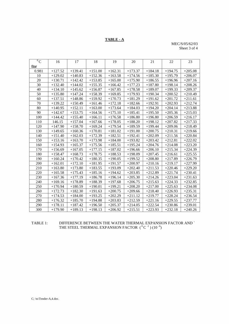
C; \ts\Tender-A,4.doc.
TABLE - AMEC/S/05/62/03
Sheet 3 of 4
0 CBar
16 17 18 19 20 21 22 23
0.981 +127.52 +139.41 +151.00 +162.31 +173.37 +184.18 +194.75 +205.0810 +129.02 +140.83 +152.36 +163.58 +174.56 +185.30 +195.79 +206.0720 +130.71 +142.42 +153.85 +165.00 +175.90 +186.55 +196.96 +207.1630 +132.40 +144.02 +155.35 +166.42 +177.23 +187.80 +198.14 +208.2640 +134.10 +145.62 +156.87 +167.85 +178.58 +189.07 +199.33 +209.3750 +135.80 +147.24 +158.39 +169.85 +179.93 +190.34 +200.52 +210.4960 +137.51 +148.86 +159.92 +170.73 +181.29 +191.62 +201.72 +211.6170 +139.22 +150.49 +161.46 +172.18 +182.66 +192.91 +202.93 +212.7480 +140.95 +152.11 +163.00 +173.64 +184.03 +194.20 +204.14 +213.8890 +142.67 +153.75 +164.56 +175.10 +185.41 +195.50 +205.36 +215.03
100 +144.42 +155.40 +166.11 +176.58 +186.80 +196.80 +206.59 +216.17110 146.15 +157.04 +167.66 +178.05 +188.20 +198.12 +207.82 +217.33120 +147.90 +158.70 +169.24 +179.54 +189.59 +199.44 +209.06 +218.49130 +149.65 +160.36 +170.81 +181.02 +191.00 +200.75 +210.31 +219.66140 +151.40 +162.03 +172.39 +182.51 +192.41 +202.09 +211.56 +220.84150 +153.16 +163.70 +173.98 +184.00 +193.82 +203.42 +212.81 +222.02160 +154.93 +165.37 +175.56 +185.51 +195.24 +204.76 +214.08 +223.20170 +156.69 +167.05 +177.15 +187.02 +196.66 +206.10 +215.34 +224.39180 +158.47 +168.73 +178.75 +188.53 +198.09 +207.45 +216.61 +225.55190 +160.24 +170.42 +180.35 +190.05 +199.52 +208.80 +217.89 +226.79200 +162.01 +172.10 +181.95 +191.57 +200.97 +210.16 +219.17 +227.99210 +163.80 +173.80 +183.55 +193.09 +202.40 +211.53 +220.46 +229.20220 +165.58 +175.43 +185.16 +194.62 +203.85 +212.89 +221.74 +230.41230 +167.36 +177.19 +186.78 +196.14 +205.30 +214.26 +223.04 +231.63240 +169.16 +178.89 +188.39 +197.68 +206.75 +215.63 +224.33 +232.85250 +170.94 +180.59 +190.01 +199.21 +208.20 +217.00 +225.63 +234.08260 +172.73 +182.30 +191.63 +200.75 +209.66 +218.40 +226.93 +235.31270 +174.53 +184.00 +193.25 +202.29 +211.12 +219.77 +228.24 +236.54280 +176.32 +185.70 +194.88 +203.83 +212.59 +221.16 +229.55 +237.77290 +178.11 +187.42 +196.50 +205.37 +214.05 +222.54 +230.86 +239.01300 +179.90 +189.13 +198.13 +206.92 +215.51 +223.93 +232.18 +240.26
TABLE 1: DIFFERENCE BETWEEN THE WATER THERMAL EXPANSION FACTOR AND `THE STEEL THERMAL EXPANSION FACTOR ( 0 C -1 ) (10 -6)
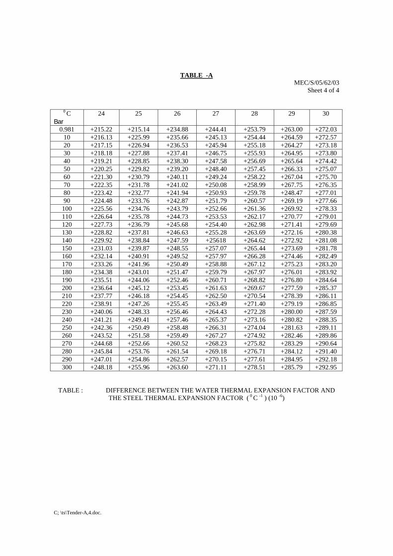
C; \ts\Tender-A,4.doc.
TABLE -AMEC/S/05/62/03
Sheet 4 of 4
0 CBar
24 25 26 27 28 29 30
0.981 +215.22 +215.14 +234.88 +244.41 +253.79 +263.00 +272.0310 +216.13 +225.99 +235.66 +245.13 +254.44 +264.59 +272.5720 +217.15 +226.94 +236.53 +245.94 +255.18 +264.27 +273.1830 +218.18 +227.88 +237.41 +246.75 +255.93 +264.95 +273.8040 +219.21 +228.85 +238.30 +247.58 +256.69 +265.64 +274.4250 +220.25 +229.82 +239.20 +248.40 +257.45 +266.33 +275.0760 +221.30 +230.79 +240.11 +249.24 +258.22 +267.04 +275.7070 +222.35 +231.78 +241.02 +250.08 +258.99 +267.75 +276.3580 +223.42 +232.77 +241.94 +250.93 +259.78 +248.47 +277.0190 +224.48 +233.76 +242.87 +251.79 +260.57 +269.19 +277.66
100 +225.56 +234.76 +243.79 +252.66 +261.36 +269.92 +278.33110 +226.64 +235.78 +244.73 +253.53 +262.17 +270.77 +279.01120 +227.73 +236.79 +245.68 +254.40 +262.98 +271.41 +279.69130 +228.82 +237.81 +246.63 +255.28 +263.69 +272.16 +280.38140 +229.92 +238.84 +247.59 +25618 +264.62 +272.92 +281.08150 +231.03 +239.87 +248.55 +257.07 +265.44 +273.69 +281.78160 +232.14 +240.91 +249.52 +257.97 +266.28 +274.46 +282.49170 +233.26 +241.96 +250.49 +258.88 +267.12 +275.23 +283.20180 +234.38 +243.01 +251.47 +259.79 +267.97 +276.01 +283.92190 +235.51 +244.06 +252.46 +260.71 +268.82 +276.80 +284.64200 +236.64 +245.12 +253.45 +261.63 +269.67 +277.59 +285.37210 +237.77 +246.18 +254.45 +262.50 +270.54 +278.39 +286.11220 +238.91 +247.26 +255.45 +263.49 +271.40 +279.19 +286.85230 +240.06 +248.33 +256.46 +264.43 +272.28 +280.00 +287.59240 +241.21 +249.41 +257.46 +265.37 +273.16 +280.82 +288.35250 +242.36 +250.49 +258.48 +266.31 +274.04 +281.63 +289.11260 +243.52 +251.58 +259.49 +267.27 +274.92 +282.46 +289.86270 +244.68 +252.66 +260.52 +268.23 +275.82 +283.29 +290.64280 +245.84 +253.76 +261.54 +269.18 +276.71 +284.12 +291.40290 +247.01 +254.86 +262.57 +270.15 +277.61 +284.95 +292.18300 +248.18 +255.96 +263.60 +271.11 +278.51 +285.79 +292.95
TABLE : DIFFERENCE BETWEEN THE WATER THERMAL EXPANSION FACTOR ANDTHE STEEL THERMAL EXPANSION FACTOR ( 0 C -1 ) (10 -6)
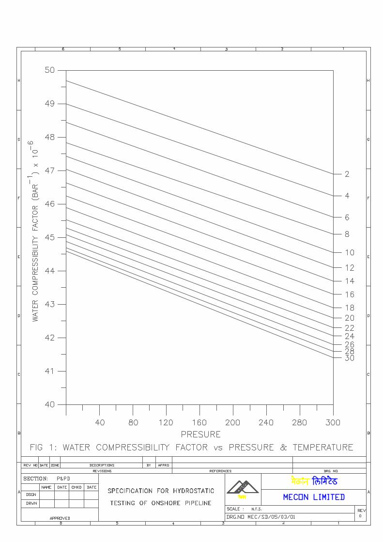
\\Akjha\work contrac\standard TS for Pipe Line WC (Vol-II) MASTER FOLDER\04A major water crossing\Major Water Crossing -Final 04.doc
SPECIFICATIONFOR
MAJOR WATER CROSSINGS(CONVENTIONAL)
SPECIFICATION NO. MEC/S/05/62/04
(PROCESS & PIPING DESIGN SECTION)MECON LIMITEDDELHI - 110 092
\\Akjha\work contrac\standard TS for Pipe Line WC (Vol-II) MASTER FOLDER\04A major water crossing\Major Water Crossing -Final 04.doc
MECON LIMITEDREGD. OFF: RANCHI (BIHAR)
PROCESS & PIPINGDESIGN SECTION
NEW DELHI
STANDARD SPECIFICATION
TITLE MAJOR WATER CROSSINGS SPECIFICATION NO. PAGE 1 OF 14
MEC/S/05/62/04 REVISION 0
C O N T E N T S
0.0 DEFINITION
1.0 SCOPE
2.0 GENERAL
3.0 TRENCHING
4.0 CONTINUOUS CONCRETE COATING
5.0 HYDROSTATIC PRE-TESTING
6.0 INSTALLATION
7.0 BACKFILLING AND BANK PROTECTION
8.0 FINAL HYDROSTATIC TEST
9.0 POST-CONSTRUCTION SURVEY
10.0 FINAL CLEAN-UP
11.0 DOCUMENTATION
PREPARED BY CHECKED BY APPROVED BY
\\Akjha\work contrac\standard TS for Pipe Line WC (Vol-II) MASTER FOLDER\04A major water crossing\Major Water Crossing -Final 04.doc
MECON LIMITEDREGD. OFF : RANCHI (BIHAR)
PROCESS & PIPINGDESIGN SECTION
NEW DELHI
STANDARD SPECIFICATION
TITLE MAJOR WATER CROSSINGS SPECIFICATION NO. PAGE 2 OF 14
MEC/S/05/62/04 REVISION 0
00 DEFINITIONA major water crossing shall be reckoned the one which will necessitatepassing the gas pipeline across a water body such as perennial river, majorirrigation canal, pond, lake, lagoon, creek etc. using special attention and means.The parameters required to classify a particular water body as a major watercrossing shall comprise of size, hydrological data, authority/ownership,importance and other ecological/ environmental factors associated with it, andthe authority to classify it such, shall rest with the COMPANY.
1.0 SCOPE
1.1 This specification covers the minimum requirements for the various activities tobe performed by CONTRACTOR for the construction of pipeline major watercrossings by conventional trenching method. Provisions of this specification areapplicable only for "major water crossings" specifically named as such in theCONTRACT.
1.2 This specification shall be read in conjunction with the conditions of allspecifications and documents included in the CONTRACT between COMPANYCONTRACTOR.
1.3 CONTRACTOR shall, with due care and diligence, execute the work incompliance with all laws, by-laws, ordinances, regulations etc. and provide allservices and labour, inclusive of supervision thereof, all materials excluding thematerials indicated as "Company supplied Materials" in the CONTRACT,equipment, appliances or other things of whatsoever nature required in or aboutthe execution of the work, whether of a temporary or permanent nature.
1.4 CONTRACTOR shall take full responsibility for the stability and safety of alloperations and methods involved in the work.
1.5 CONTRACTOR shall be deemed to have inspected and examined the workarea and its surroundings and to have satisfied himself so far as practicable asto the form and nature thereof, including sub-surface conditions, hydrologicaland climatic conditions, the extent and nature of the work and materialsnecessary for the completion of the work, and the means of access to the workarea.
1.6 CONTRACTOR shall be deemed to have obtained all necessary information asto risks, contingencies and all other circumstances, which may influence thework w.r.t. the above.
\\Akjha\work contrac\standard TS for Pipe Line WC (Vol-II) MASTER FOLDER\04A major water crossing\Major Water Crossing -Final 04.doc
MECON LIMITEDREGD. OFF : RANCHI (BIHAR)
PROCESS & PIPINGDESIGN SECTION
NEW DELHI
STANDARD SPECIFICATION
TITLE MAJOR WATER CROSSINGS SPECIFICATION NO. PAGE 3 OF 14
MEC/S/05/62/04 REVISION 0
1.7 CONTRACTOR shall, in connection with the work, provide and maintain athis own costs all lights, guards, fencing, watching etc., when and wherenecessary or required by COMPANY or by any duly constituted authorityfor the protection of the work and properties or for the safety and theconvenience of public and/ or others.
1.8 For the purpose of this specification, the following definitions shall hold :
• the words `Shall' and `Must' are mandatory• the words `Should', `May' and `Will' are non-mandatory, advisory, or
recommended.
2.0 GENERAL
2.1 All works of the pipeline major water crossing shall be performed in accordancewith the approved construction drawings, procedures, other applicabledocuments as per the CONTRACT, good pipeline practice and as directed byCOMPANY.
2.2 Before start of the field construction, CONTRACTOR shall submit toCOMPANY, for approval for each major water crossing a complete reportcontaining at the minimum :-
i) installation method
ii) proposed time schedule indicating start and finish dates and detailedbreak-up of time period for all critical activities associated with the work.
iii) required work area along with layout and location
iv) equipment to be used (including number and capacity of equipment).
v) manpower deployment during construction
vi) proposed sub-contractors and/ or vendors along with their scope of work.
The description of the installation method as a minimum shall include thefollowing:
a) Study of water currents in relation to the method of launching (on bottomand on surface).
b) Calculation for stability of pipeline during launching and final test.
\\Akjha\work contrac\standard TS for Pipe Line WC (Vol-II) MASTER FOLDER\04A major water crossing\Major Water Crossing -Final 04.doc
MECON LIMITEDREGD. OFF : RANCHI (BIHAR)
PROCESS & PIPINGDESIGN SECTION
NEW DELHI
STANDARD SPECIFICATION
TITLE MAJOR WATER CROSSINGS SPECIFICATION NO. PAGE 4 OF 14
MEC/S/05/62/04 REVISION 0 c) Buoyancy studies
d) Preparation of fabrication yard and launching areas.
e) Pipeline construction details (handling, stringing, welding, concretecoating etc.)
f) Pre-test procedure including trial mix, design & tests for concrete coating.
g) Procedure for corrosion coating of field joint
h) Dredging, anchoring program, spoil-deposit and trench survey methodincluding facilities for COMPANY.
i) Pulling or other installation method and related calculations.
j) Pulling arrangement including launchway and anchoring and breakingdevice.
k) Trench correction before launching.
l) Method of positioning and sinking of pipeline.
m) Method of rectification of damages to the pipeline, during launching.
n) Method of backfilling, bank protection and survey.
o) Final test procedure after backfilling.
p) Safety systems during launching, rope tests.
q) Communication.
r) Abandonment and recovery procedures concurred.
s) Necessary permission from concerned authorities for crossing.
COMPANY shall inform CONTRACTOR within 21 days if any objection againstthe document and procedure described requires resubmission byCONTRACTOR.
Approval by COMPANY of the methods used by CONTRACTOR shall in no wayrelieve CONTRACTOR from the sole responsibility for safe and satisfactoryinstallation of the crossing.
\\Akjha\work contrac\standard TS for Pipe Line WC (Vol-II) MASTER FOLDER\04A major water crossing\Major Water Crossing -Final 04.doc
MECON LIMITEDREGD. OFF : RANCHI (BIHAR)
PROCESS & PIPINGDESIGN SECTION
NEW DELHI
STANDARD SPECIFICATION
TITLE MAJOR WATER CROSSINGS SPECIFICATION NO. PAGE 5 OF 14
MEC/S/05/62/04 REVISION 0 2.3 CONTRACTOR shall comply with all the conditions and requirements issued by
authorities having jurisdiction in the area where the work is to be performed.CONTRACTOR shall, at his own responsibility, obtain necessary permits fromthe authorities having jurisdiction, for performing his work.If no public roads exist, CONTRACTOR shall arrange on his own for access tohis work area at no extra cost to COMPANY.
2.4 Pre-construction Surveys
Prior to start of any work, CONTRACTOR shall carry out a survey of the majorwater crossings and acquaint himself with site conditions and to collect any dataregarding the water velocity and the tidal variations in the flow pattern and shallverify the suitability of his equipment and the methods of construction.
3.0 TRENCHING
3.1 Dredging/ Excavating
3.1.1 CONTRACTOR shall dredge or excavate the trench for the water crossing inconformity with the approved drawings. Dredging of the trench shall be executedas accurately as possible.
3.1.2 The trench shall be excavated to such depth as required to provide the minimumcover and the pipeline configuration as specified. The pipeline profile of thecrossings shall be followed as accurately as possible. Before laying, the trenchshall be cleaned and levelled. The trench shall be subject to inspection byCOMPANY prior to installation of the pipe.
3.1.3 Navigational traffic shall not be obstructed, unless permission has been giventhereto. CONTRACTOR shall issue all necessary publications according to thelocal regulations. Instructions given by authorities shall be followed accuratelyand immediately, so that there in no hindrance to traffic. For stoppage ofnavigational traffic public notification, PA system, signal/ sign etc. shall beprovided.
CONTRACTOR cannot request a compensation if his work is hampered ordelayed due to weather conditions, any obstacles/ or by any traffic on the spot,where work is executed.
3.1.4 CONTRACTOR is fully responsible for the execution of the blasting (wheneverpermitted) the dredging and excavation work, hopping of the soil, transportation,dumping on land or in water, all to be executed in agreement with authorities,land owners and COMPANY.
\\Akjha\work contrac\standard TS for Pipe Line WC (Vol-II) MASTER FOLDER\04A major water crossing\Major Water Crossing -Final 04.doc
MECON LIMITEDREGD. OFF : RANCHI (BIHAR)
PROCESS & PIPINGDESIGN SECTION
NEW DELHI
STANDARD SPECIFICATION
TITLE MAJOR WATER CROSSINGS SPECIFICATION NO. PAGE 6 OF 14
MEC/S/05/62/04 REVISION 0
3.1.5 CONTRACTOR may be obliged to dredge or excavate a trench deeper or widerthan indicated in the drawings in order to properly lay the pipeline in unstable(underwater) areas, or near and adjacent to the banks of water courses. It shallbe understood that CONTRACTOR is aware of such problems at the time of thisbid and that, when such additional excavation is required, it shall be done byCONTRACTOR as part of the work and that he will install the necessaryprovision and/ or temporary works such as sheet-piling, special filling materials,etc. at no extra cost to COMPANY.
3.1.6 During, the execution of dredging work of CONTRACTOR, bearings,measurements and levels shall be taken by or on behalf of COMPANY.CONTRACTOR shall render assistance for this purpose and make available forCOMPANY appropriate survey boats, fully manned and equipped before thestart of excavation work of the water crossing trench. CONTRACTOR, if sodesired by COMPANY, shall make cross profiles at intervals of not more than10.0m of the bottom of the water-course along the surveyed center line of thewater crossing. In such a case horizontal measurements shall be taken bytriangulation or taping between known points and shall be made with suchaccuracy that the location of each vertical measurement is known within 1.0m.Vertical measurements shall be taken with a sonic recording device, or with lineand rod, as directed by COMPANY and shall be taken with such accuracy thateach depth is known within 0.2m. Vertical measurements shall be taken at pointsaveraging not more than 5.0m apart and no two measurements shall be morethan 7.0m apart. The cross profiles shall extend at least 10m on both sides ofthe top of the trench.
All measurements shall be witnessed by COMPANY. The resulting profile,corrected to the elevation of the undisturbed water-course, shall then be thereference profile. Said profile shall be plotted on a 1:200 vertical and horizontalscale.
3.1.7 CONTRACTOR shall keep the trench in good condition until the pipe is laid, andno claim is to be made to the COMPANY by reason of its caving either before orafter the pipe is laid. CONTRACTOR shall do whatever is required to excavatethe trench, install the pipe in it and backfill the trench in accordance with thesespecifications at no extra cost to COMPANY.

\\Akjha\work contrac\standard TS for Pipe Line WC (Vol-II) MASTER FOLDER\04A major water crossing\Major Water Crossing -Final 04.doc
MECON LIMITEDREGD. OFF : RANCHI (BIHAR)
PROCESS & PIPINGDESIGN SECTION
NEW DELHI
STANDARD SPECIFICATION
TITLE MAJOR WATER CROSSINGS SPECIFICATION NO. PAGE 7 OF 14
MEC/S/05/62/04 REVISION 0
3.1.8 Immediately before installation of the water crossing in the excavated trench,CONTRACTOR shall prepare a profile of the trench bottom along the surveyedcenter line of the water crossing for comparison with the reference profile.CONTRACTOR shall also make cross sections of the trench at intervals of notmore than 100m. All profile and cross section measurements shall be taken asspecified and shall be witnessed by COMPANY. These data shall be submittedto COMPANY for approval and COMPANY will approve or reject the trenchexcavation as completed within 24 hours after receipt of the profile and crosssections.
3.1.9 CONTRACTOR shall grade the trench in such a manner as to give themaximum amount of uniform support to the pipeline when it is lowered or pulledinto place. The maximum unsupported span shall not exceed 10.0m.
3.1.10 In submerged sections, where rock or gravel is encountered in the bottom of thetrench, padding is required. The thickness of the padding under the concretecoated pipe shall at least be 50 cm and after installation at least 50 cm aroundthe pipe.
Blasting, if any, and padding shall be included in the work.
3.2 Pumping Line
In case CONTRACTOR uses pumping lines to discharge the spoil, he shall takecare of the necessary permits.
Pumping lines, discharges and siphons shall be installed by CONTRACTOR andremoved before the completion of the work. At crossings with existing roads, thepumping lines shall be led through a casing pipe bored/ jacked under the road orled through a porch over the road. A stress calculation must then be handedover to COMPANY. The necessary provisions to embank the dumping area andalso the spoil basins shall be made by CONTRACTOR. CONTRACTOR isresponsible for transportation of the soil and dumping on land and is liable fordamage to works of third parties caused by leakage of pumping lines, etc.CONTRACTOR shall at all time prevent overflow of pumping water, spoil orsand over embankments, parcels or roads. Further more, CONTRACTOR shallsafeguard COMPANY from claims of compensation by third parties due toencountered damage.

\\Akjha\work contrac\standard TS for Pipe Line WC (Vol-II) MASTER FOLDER\04A major water crossing\Major Water Crossing -Final 04.doc
MECON LIMITEDREGD. OFF : RANCHI (BIHAR)
PROCESS & PIPINGDESIGN SECTION
NEW DELHI
STANDARD SPECIFICATION
TITLE MAJOR WATER CROSSINGS SPECIFICATION NO. PAGE 8 OF 14
MEC/S/05/62/04 REVISION 0
3.3 Spoil
Spoil which is not dumped on and including spoil acquired after cleaning thewater crossing trench, shall be transported and dumped in places, designatedthereto by agreement between CONTRACTOR and authorities and approved ofby COMPANY. Spoil shall be transported in (split) barges; only those bargesshall be used that avoid spilling during transportation due to incorrect closing ofthe flaps, etc. Spoil which is dumped outside the designated places shall beremoved by CONTRACTOR at first notice by COMPANY.
3.4 Dykes, Dams and Weirs
CONTRACTOR shall install temporary provisions in the existing dykes, dams,etc. to prevent flooding of low areas.
Therefore in general, in existing dykes, dams, etc a double substituting weirmust be installed before start of excavation in the existing dyke or dam. Such adouble substituting weir can be a closed wall of sheet piling, supported by soil.The provisions shall be such that the underwater profile of the dredged trench,the water movement caused by ships, etc. cause no slides/ cave-ins of the dykeor dam.
4.0 CONTINUOUS CONCRETE COATING
CONTRACTOR shall provide concrete coating over the pipeline including thebends in accordance with the specification issued for the purpose (referspecification no. MEC/S/05/11/03 and approved procedure. CONTRACTORshall coat the weld joints in order to arrive at a continuously concrete coatedpipeline. However this concrete coating shall be applied after the hydrostaticpretest.
5.0 HYDROSTATIC PRE-TESTING
CONTRACTOR shall hydrostatically pre-test the pipe string of each watercrossing before installation as per approved procedure.
Joint coating of the welds shall be done after this pre-test.
The section of the pipeline corresponding to the major water crossing shall,before installation, be subjected to hydrostatic pre-testing to a combined equivalent stress of 90% of the SMYS of the pipe material.
\\Akjha\work contrac\standard TS for Pipe Line WC (Vol-II) MASTER FOLDER\04A major water crossing\Major Water Crossing -Final 04.doc
MECON LIMITEDREGD. OFF : RANCHI (BIHAR)
PROCESS & PIPINGDESIGN SECTION
NEW DELHI
STANDARD SPECIFICATION
TITLE MAJOR WATER CROSSINGS SPECIFICATION NO. PAGE 9 OF 14
MEC/S/05/62/04 REVISION 0
After the temperature has been stabilised, the pressure shall be maintained inthe pipeline for at least twenty four hours and recorded by manothermograph.During the test CONTRACTOR shall check all welds for leakage. Failure, if any,during the test shall be rectified by the CONTRACTOR. If the same is due tofailure on account of any cause other than defect in material supplied byCOMPANY, the repairs shall be done free of cost, to the satisfaction ofCOMPANY.
6.0 INSTALLATION
6.1 CONTRACTOR shall submit a detailed scheme for the method he proposes toadopt for installing the pipeline to COMPANY for approval. CONTRACTOR shallcalculate all stresses in the pipeline while laying and check whether the stressesremain within permissible limits. A set of all calculations shall be submitted to theCOMPANY for approval.
6.2 CONTRACTOR shall perform all work required to install the water crossings,including the possible appurtenances indicated in the drawings. The watercrossings shall be installed in such a manner as to comply with the requirementsand conditions stated by the Authorities issuing the permits. CONTRACTORshall pay special attention to minimize any damage to embankments and dykesin the vicinity of water crossings.
6.3 The equipment for launching shall be arranged in such a way that the pipeline islaid without impact or jerking and is not subjected to stresses of any type otherthan those which are allowable. Minimum allowed radius of curvature shall befollowed, particularly at the end of the launching way towards the water in thefreely suspended section.
6.4 After the water-crossing section has been installed in place, CONTRACTORshall fill this section including the pertaining land sections with water for the finaltesting.
6.5 CONTRACTOR shall check if the position and depth of the water crossing are inaccordance with the approved drawings, by means of a profile of the pipeline,before and after the water-crossing section is filled with water. CONTRACTORshall lower each pipeline section which is not sufficiently deep by dredging orjetting the underlying ground.
\\Akjha\work contrac\standard TS for Pipe Line WC (Vol-II) MASTER FOLDER\04A major water crossing\Major Water Crossing -Final 04.doc
MECON LIMITEDREGD. OFF : RANCHI (BIHAR)
PROCESS & PIPINGDESIGN SECTION
NEW DELHI
STANDARD SPECIFICATION
TITLE MAJOR WATER CROSSINGS SPECIFICATION NO. PAGE 10 OF 14
MEC/S/05/62/04 REVISION 0
6.6 The maximum allowed horizontal deviation from the required center line shall belimited to the following :-
For pipeline dia. upto and including 24" - 300 mmFor pipeline dia greater than 24" - 500 mm
6.7 Prior to backfill the pipeline shall, when laid in the trench, conform to the bottomcontour of the trench grade, so that it will be firmly, uniformly and continuouslysupported. COMPANY may employ a diver or use other suitable methods toinspect the bottom of the trench and/ or after the pipe is installed prior tobackfilling of the trench. CONTRACTOR shall facilitate the work of the diver andshall furnish the necessary equipment and helpers (other than actual divingequipment) necessary for the diver/ inspector to perform his work.
6.8 If the pipe does not properly fit the trench or does not rest at sufficient depth tosatisfy the minimum requirements of cover as specified in approved drawings,the CONTRACTOR shall make necessary corrections to either trench or thepipe alignment or to both so that the pipe, when finally in position in the trench,shall fully meet the specifications, failing which CONTRACTOR may be asked toremove the pipeline. This shall be done at no extra to the COMPANY.
6.9 Installation of Parallel Pipelines
When parallel pipelines are required to be installed for a major water crossing.CONTRACTOR shall further comply with the following requirements.
6.9.1 Depending on the diameters of the parallel pipelines, the characteristics of thecrossing and the limitations of CONTRACTOR's equipment, CONTRACTORmay propose installation of the parallel pipelines either together in a combinedoperation or separately in a common trench.
6.9.2 If the pipelines are installed together, the minimum clear distance between theparallel pipelines (measured from the outside diameters of the concrete coatedpipes) shall be 300mm. CONTRACTOR shall provide spacers at sufficientintervals along the length of the pipe section(s), securely fixed to the pipes, orshall propose other suitable alternative methods, so as to ensure that thestipulated minimum clear distance is maintained. The spacers may be removedbefore the trench is backfilled.
\\Akjha\work contrac\standard TS for Pipe Line WC (Vol-II) MASTER FOLDER\04A major water crossing\Major Water Crossing -Final 04.doc
MECON LIMITEDREGD. OFF : RANCHI (BIHAR)
PROCESS & PIPINGDESIGN SECTION
NEW DELHI
STANDARD SPECIFICATION
TITLE MAJOR WATER CROSSINGS SPECIFICATION NO. PAGE 11 OF 14
MEC/S/05/62/04 REVISION 0
CONTRACTOR shall furnish detailed drawings for the pipe assembly showingthe details of spacers/ other arrangements for COMPANY's approval beforestart of construction.
6.9.3 If the parallel pipelines are installed separately in a common trench, theminimum clear distance between the parallel pipelines in the trench shall be5000mm. CONTRACTOR shall ensure that this minimum spacing bemaintained till the time the trench is backfilled.
7.0 BACKFILLING AND BANK PROTECTION
7.1 Backfilling of the water-crossing section shall be performed as described in thefollowing clauses.
7.1.1 The bottom of the waterway shall be reinstated to its original level by backfillingthe trench in a manner and with suitable material and as prescribed andapproved by the authorities and COMPANY. In case material other than theoriginal spoil is required, this shall be supplied and applied by CONTRACTOR.
Wherever boulders, rock, gravel and other hard object are encountered, theyshall not be placed directly on the pipe. Sufficient earth, and or selected andapproved backfill material shall be backfilled initially around and over the pipe toprovide a protective padding or cushion extending to a minimum thickness of 50centimeters around the pipe before backfilling remainder of the trench withexcavated or other material.
Wherever required by COMPANY, CONTRACTOR shall cover the (nearly)backfilled trench with a layer of rock boulders to be approved by COMPANYover a width equal to the width of the excavated trench with an extra of 5 m oneither side at no extra cost to COMPANY.
7.1.2 Backfilling progress of the trench shall be checked continuously, and a dailyprogress report shall be made and handed over to COMPANY.
7.1.3 All embankments and/ or dykes, bed and banks shall be reinstated to theiroriginal state and levels, unless otherwise prescribed in the drawings or by theCompetent authorities or COMPANY.
7.1.4 All remaining spoil-deposits shall be cleaned by CONTRACTOR to thesatisfaction of COMPANY.
\\Akjha\work contrac\standard TS for Pipe Line WC (Vol-II) MASTER FOLDER\04A major water crossing\Major Water Crossing -Final 04.doc
MECON LIMITEDREGD. OFF : RANCHI (BIHAR)
PROCESS & PIPINGDESIGN SECTION
NEW DELHI
STANDARD SPECIFICATION
TITLE MAJOR WATER CROSSINGS SPECIFICATION NO. PAGE 12 OF 14
MEC/S/05/62/04 REVISION 0
7.2 Bank Protection
7.2.1 Trenches in banks of major water crossings shall be backfilled with soilapproved by COMPANY. The fill at the banks shall be tamped firmly andreinforced with sacked earth, rip-rap, or by other means as directed byCOMPANY to the satisfaction of authorities having jurisdiction thereof. In areaswhere the backfilled soil is expected to be of loose type which is prone to flow,the trench shall be backfilled with boulder/ crushed rock of minimum 75mmthickness. The boulder/ crushed rock shall be derived from solid, stable, non-soluble and approved quality store approved by COMPANY and pipe shall beprovided with adequate padding of soil of a quality approved by COMPANY.Wherever necessary the boulder/ crushed rock shall be held to the bed by useof 6.1 wire nets of minimum dia. of 3.2mm, made from steel having tensilestrength of 400 N/mm2 and with a minimum elongation at failure of 12%. Theminimum zinc coating of 275 gm-2 shall be applied on single/ double twistedwire. After the trench has been backfilled and during the clean up works, thewater crossing shall be cleaned across the whole width of ROW. The existingbed profile shall be maintained after restorations.
7.2.2 Unless stipulated otherwise by the authorities or by COMPANY, CONTRACTORshall protect the banks of the major water crossings by using gravel andboulders filled embankment mattresses of galvanized iron wire (of specificationas in 7.2.1 above) to be laid over the backfilled, compacted and graded banks.In case slope of the banks is 1:1 or more, bank protection shall be carried outusing gabions. Bank protection works shall be carried out by CONTRACTOR inaccordance with the drawings included in the CONTRACT. All materials requiredfor such works shall be supplied by CONTRACTOR and all works carried out inaccordance with specifications, approved drawings, instructions of COMPANYand to the complete satisfaction of authorities having jurisdiction at no extra costto COMPANY.
The length of the above protection shall be equal to the actual bank excavationedge including damage and further extending 10 m on either sides, The width ofthe restoration on the slope shall be determined by the levels :• 2m above Highest Water Level, (recordable) or upto the top of bank ,
whichever is higher.• 5m below Low Water Level (recordable) or upto pipe trench level in the
bed.
7.2.3 Before final hydrostatic testing, CONTRACTOR shall `prove' the diameter of thepipeline by passing a gauging (caliper) pig through the pipeline. The gaugingpig shall have a diameter equal to 95% of the internal diameter of thepipe.
\\Akjha\work contrac\standard TS for Pipe Line WC (Vol-II) MASTER FOLDER\04A major water crossing\Major Water Crossing -Final 04.doc
MECON LIMITEDREGD. OFF : RANCHI (BIHAR)
PROCESS & PIPINGDESIGN SECTION
NEW DELHI
STANDARD SPECIFICATION
TITLE MAJOR WATER CROSSINGS SPECIFICATION NO. PAGE 13 OF 14
MEC/S/05/62/04 REVISION 0
CONTRACTOR shall supply and install all temporary scraper, launchers.Receivers and other equipment, piping and materials and consumables forthe purpose.
8.0 FINAL HYDROSTATIC TEST
The complete water crossing must be tested immediately after the approvedbackfilling of the trench. The test procedure shall result in a hoop stress in pipecorresponding to 90% SMYS of the pipe material. After temperature stabilisationpressure shall be retained in the pipeline for a minimum of 4 hours and recordedby manothermograph. The hydrostatic testing shall be carried out in accordancewith approved procedures.
9.0 POST-CONSTRUCTION SURVEY
After laying of the pipeline, CONTRACTOR shall carry out a post-constructionsurvey jointly with COMPANY. Any defects brought to the notice ofCONTRACTOR shall be promptly corrected by CONTRACTOR at his ownexpense to the complete satisfaction of COMPANY.
10.0 FINAL CLEAN-UP
After completion of construction, CONTRACTOR shall clear the site of allbalance material and debris. All balance pipe lengths, in case supplied byCOMPANY, shall be returned to COMPANY's designated stock yard(s). Siteshall be cleared to the complete satisfaction of COMPANY and authoritieshaving jurisdiction. All such works shall be done at no extra cost to COMPANY.
11.0 DOCUMENTATION
11.1 In addition to the documents specified elsewhere in this specification.CONTRACTOR shall submit to the COMPANY six copies of each of thefollowing documents / records.
• Complete record of pipes `taken-over' from COMPANY, number of pipelengths used, and record of return of balance pipe lengths toCOMPANY's designated stock-yard(s).
• Copies of the permits obtained from authorities having jurisdiction for thevarious works.
• Records of Non-destructive testing of welds.
\\Akjha\work contrac\standard TS for Pipe Line WC (Vol-II) MASTER FOLDER\04A major water crossing\Major Water Crossing -Final 04.doc
MECON LIMITEDREGD. OFF : RANCHI (BIHAR)
PROCESS & PIPINGDESIGN SECTION
NEW DELHI
STANDARD SPECIFICATION
TITLE MAJOR WATER CROSSINGS SPECIFICATION NO. PAGE 14 OF 14
MEC/S/05/62/04 REVISION 0
• Clearance certificates from the land owners and authorities havingjurisdiction regarding satisfactory clean-up and restoration of pipelineROU and work areas.
11.2 After completion of construction CONTRACTOR shall prepare & furnish six setsof copies and two sets of reproducible of As-built drawing for the crossings.
As-built drawings shall be as a minimum, include the following information.
• True profile of the bed and banks of the water crossing along the pipelineafter backfilling.
• True profile of the pipeline as installed and the top of cover to top of pipeat regular intervals.
• Location and angle of sag and over bends.
• Extent of backfill.
• Extent of bank protection.
11.3 All documents shall be in English Language
\\Akjha\work contrac\standard TS for Pipe Line WC (Vol-II) MASTER FOLDER\05 pipeline crossing road,railroad , minor water etc\PCR-MWC final-1 05.doc
SPECIFICATIONFOR
PIPELINES CROSSING ROADS,RAILROADS, MINOR WATER
AND OTHER CROSSINGS
SPECIFICATION NO. MEC/S/05/62/05
(PROCESS & PIPING DESIGN SECTION)MECON LIMITEDDELHI - 110 092
\\Akjha\work contrac\standard TS for Pipe Line WC (Vol-II) MASTER FOLDER\05 pipeline crossing road,railroad , minor water etc\PCR-MWC final-1 05.doc
MECON LIMITEDREGD. OFF: RANCHI (BIHAR)
PROCESS & PIPINGDESIGN SECTION
NEW DELHI
STANDARD SPECIFICATION
TITLE SPECIFICATION NO. PAGE 1 OF 10PIPELINES CROSSING ROADS,RAILROADS, MINOR WATER ANDOTHER CROSSINGS MEC/S/05/62/05 REVISION 0
C O N T E N T S
1.0 SCOPE
2.0 GENERAL
3.0 ROAD AND RAIL-ROAD CROSSINGS
4.0 CROSSINGS OF BURIED SERVICES
5.0 MINOR WATER COURSE CROSSINGS
PREPARED BY CHECKED BY APPROVED BY

\\Akjha\work contrac\standard TS for Pipe Line WC (Vol-II) MASTER FOLDER\05 pipeline crossing road,railroad , minor water etc\PCR-MWC final-1 05.doc
MECON LIMITEDREGD. OFF : RANCHI (BIHAR)
PROCESS & PIPINGDESIGN SECTION
NEW DELHI
STANDARD SPECIFICATION
TITLE SPECIFICATION NO. PAGE 2 OF 10PIPELINES CROSSING ROADS,RAILROADS, MINOR WATER AND OTHER CROSSINGS MEC/S/05/62/05 REVISION 0
1.0 SCOPE
1.1 This specification covers the minimum requirement for the various activities tobe carried out by the CONTRACTOR for or about the installation of pipelinescrossing roads, railroads, minor water courses and other services.
The provisions of this specification are not applicable for pipelines crossingwater courses, which are specifically designated as "Major Water Courses" inthe CONTRACT.
1.2 This specification shall be road in conjunction with the conditions of allspecifications and documents included in the CONTRACT between COMPANYand CONTRACTOR.
For the purpose of this specification the following definitions shall hold :
• the words "Shall" and "Must" are mandatory• the words "Should, "May" and "Will" are non-mandatory, advisory
recommended.
2.0 GENERAL
2.1 Crossing of roads, railroads, buried services, canals and minor water courseswith equipment and/ or personnel is allowed only after acquiring approval fromthe authorities having jurisdiction and after making arrangements forsafeguarding the roads, etc. and the buried services with appropriate provisions.
Highways, main-roads and railroads and their verges and banks of watercrossings are not allowed to be used for loading, unloading or stacking ofmaterials and/ or equipment. For secondary roads, such loading/ unloading ispermitted only after prior approval from the concerned authoritiesCONTRACTOR is not allowed to close or divert roads or water courses withoutprior approval from the COMPANY and the concerned authorities.CONTRACTOR shall never unnecesarilly hamper the users of the roads,railroads, buried services and/ or water courses. The water flow shall not beobstructed in any way.
2.2 COMPANY reserves the right to demand for individual crossings from theCONTRACTOR a separate detailed report for approval, containing :
• Time schedule
\\Akjha\work contrac\standard TS for Pipe Line WC (Vol-II) MASTER FOLDER\05 pipeline crossing road,railroad , minor water etc\PCR-MWC final-1 05.doc
MECON LIMITEDREGD. OFF : RANCHI (BIHAR)
PROCESS & PIPINGDESIGN SECTION
NEW DELHI
STANDARD SPECIFICATION
TITLE SPECIFICATION NO. PAGE 3 OF 10PIPELINES CROSSING ROADS,RAILROADS, MINOR WATER ANDOTHER CROSSINGS MEC/S/05/62/05 REVISION 0
• Working method with equipment• Test procedure• Manpower deployment• Calculations of temporary works• Soil investigations, etc.
Such works shall be without any extra cost to COMPANY.
2.3 Pipeline crossings for road, railroad, canals and rivers etc., shall behydrostatically pretested ex-situ, prior to joint coating, whenever,
• Crossing is executed by boring ;
• Crossing is installed in casing pipe;
• River crossing pipes which are to be continuously concrete weight coated(to be tested prior to concrete coating);
• Whenever, in COMPANY's opinion, the repair of pipeline at crossing, incase of a leak during final hydrostatic testing, would require inordinateamount of effort and/ or time;
• Whenever pretesting is insisted upon by the Authorities havingjurisdication over the utility crossed.
The section of the pipeline for the crossings shall be tested as a single string.Unless specified otherwise in the CONTRACT, the test pressure shall be theone resulting in a hoop stress corresponding to 90% of SMYS of pipe material.Test pressure shall be retained in the pipeline for minimum period of 2 hours.Test section shall be visually examined for leaks/ defects, etc.
3.0 ROAD AND RAILROAD CROSSINGS
3.1 The work under crossings shall include necessary clearing, grading andtrenching to required depths and widths, welding of casing (when required) andcarrier pipes, coating, lowering-in, backfilling, clean-up, restoration to the originalcondition and further strengthening and protective works, testing, installation ofassemblies, insulators and seals, and temporary works such as sheet pilling,bridges, etc.
\\Akjha\work contrac\standard TS for Pipe Line WC (Vol-II) MASTER FOLDER\05 pipeline crossing road,railroad , minor water etc\PCR-MWC final-1 05.doc
MECON LIMITEDREGD. OFF : RANCHI (BIHAR)
PROCESS & PIPINGDESIGN SECTION
NEW DELHI
STANDARD SPECIFICATION
TITLE SPECIFICATION NO. PAGE 4 OF 10PIPELINES CROSSING ROADS,RAILROADS, MINOR WATER ANDOTHER CROSSINGS MEC/S/05/62/05 REVISION 0
The work shall be carried out in accordance with the approved drawings and jobstandards, as directed by COMPANY and to the satisfaction of COMPANY andthe authorities having jurisdication over th facility crossed. The work carried outfor road and railroad crossings shall meet the minimum requirements of API RP1102, latest edition.
Before the installation work of crossings is started, the CONTRACTOR shallprovide suitable barricades, temporary bridge/ bypass work (especially whereroads are open-cut) with railing, if required by COMPANY for safety of traffic.Adequate traffic warning signals and/ or traffic lights and suitable diversions shallbe provided as directed by COMPANY/ Authority having jurisdication over theseareas. Such diversions shall not cross the pipeline where it has already beeninstalled, unless proper safeguarding in COMPANY's opinion is ensured.
Prior approval from the statutory authorities shall be obtained to lay the pipelineacross highways/ roads either by boring or by open-cut method. Installation ofthe crossing shall be by the method (i.e., boring/ open-cut) approved byAuthorities having jurisdiction. Railroad crossings shall always be bored/ jacked.
3.2 Boring/ jacking of carrier pipes for crossings is allowed only if the pipes forboring/ jacking are provided with a suitable corrosion coating andCONTRACTOR remains liable for the suitablity of the pipe and weld-coating ofcarrier pipes to be bored and for which coating and method of application areanyhow to be authorised by COMPANY without prejudice to CONTRACTOR'sliability. In all other cases the carrier pipes shall be cased.
Before start of the boring/ jacking CONTRACTOR shall execute a soilinvestigation and determine the ground water table. Based on theseinvestigations CONTRACTOR shall prepare a construction drawing and submitto COMPANY for approval including time schedule and soil investigation report.The CONTRACTOR shall submit for approval of COMPANY the method ofboring / trenchless to be carried out, depending on the nature of soil conditions, nature of crossing, local requirements etc.
During the execution of boring the ground water table over the length of theboring shall be lowered up to atleast 0.50 M below bottom of the pipeline. Thiswater table is to be regularly inspected and maintained by CONTRACTOR andreported to COMPANY. To safeguard the stability of the borepit, CONTRACTORshall, if necessary in COMPANY's opinion, use a closed sheetpiling which shallextend atleast over 50% of the length in undisturbed soil. The length of theboring shall be in accordance with the length of the ROW of the crossing (road,railroad, etc.) with minimum 0.6 m extra on either side.
\\Akjha\work contrac\standard TS for Pipe Line WC (Vol-II) MASTER FOLDER\05 pipeline crossing road,railroad , minor water etc\PCR-MWC final-1 05.doc
MECON LIMITEDREGD. OFF : RANCHI (BIHAR)
PROCESS & PIPINGDESIGN SECTION
NEW DELHI
STANDARD SPECIFICATION
TITLE SPECIFICATION NO. PAGE 5 OF 10PIPELINES CROSSING ROADS,RAILROADS, MINOR WATER ANDOTHER CROSSINGS MEC/S/05/62/05 REVISION 0
If the soil conditions and groundwater for a particular boring give reasons forthis, CONTRACTOR is entitled to suggest to COMPANY for a relaxation of oneor more of the following requirements as defined hereforth :
• Soil investigation• Lowering of groundwater table• Sheetpiling• Length of boring etc.
In approaches to the crossing, CONTRACTOR shall eliminate unnecessarybending of pipe by conforming to the contour of the ground by graduallydeepening the ditch at such approaches as directed by the COMPANY.
3.3 The bottom of the trench and/ or the pit for at least twelve (12) metres at theapproach to each end of a casing shall be graded and if necessary backfilledwith clean sand and compacted upto atleast 95% Proctor density to an elevationthat will provide sufficient and continuous support to the pipeline so that thepipeline remains correctly aligned at the casing ends during and after backfilling.
3.4 The diameter of the hole for a bored section shall have a hole diameter as closeas practicable to the outside diameter of the carrier or casing pipe. If excessivevoid or too large hole results, or if it is necessary, in the opinion of COMPANY,to abandon the bored hole, prompt remedial measures such as filling the holewith suitable material shall be taken to the entire satisfaction of the COMPANYand Authorities having jurisdication thereof at no extra cost to COMPANY.Equipment used for installation of casing pipe shall be of the type approved byCOMPANY.
An installation consisting of hydraulic jacks shall be provided with easilyreadable pressure gauges (in bar) and sealable pressure limits. Their properoperation shall be demonstrated before the work is started. COMPANY canrequest that the maximum pressing force be limited.
At the front of the pipe there may be a cutting ring which may be 12mm largerthan the outside diameter for the pipe or casing. A lubricating pipe can also beused in jacking, the nipples of which shall not protrude from the cutting edge.Said lubricating pipe shall not be fixed to the pipe casing. When jacking, onlybiologically degradable lubricants shall be used (e.g. WRC Medlube or anemulsion of bentonite).
\\Akjha\work contrac\standard TS for Pipe Line WC (Vol-II) MASTER FOLDER\05 pipeline crossing road,railroad , minor water etc\PCR-MWC final-1 05.doc
MECON LIMITEDREGD. OFF : RANCHI (BIHAR)
PROCESS & PIPINGDESIGN SECTION
NEW DELHI
STANDARD SPECIFICATION
TITLE SPECIFICATION NO. PAGE 6 OF 10PIPELINES CROSSING ROADS,RAILROADS, MINOR WATER ANDOTHER CROSSINGS MEC/S/05/62/05 REVISION 0
Removal of soil from the pipeline during jacking shall be done mechanically bymeans of a standard, locked auger, which has to be safeguarded against jackingahead of the pipe.
During jacking the progress of the pipe to be jacked and the cutting capacity ofthe auger shall be mutually adjusted, by regulating the speed of the auger, toprevent the road from bulging (rpm too low) or cave-ins (rpm too high). In anycase no more soil shall be removed than the volume of the pipe. The auger driveshall be provided with a clutch.
The progress in the work, the readings of the gauge pipes, the jacking pressuresobserved, etc., shall be recorded in a log book, to be shown to COMPANY uponrequest. All information shall be supplied to COMPANY on completion of thework.
If the jacking fails, the casing shall not be withdrawn. It shall be filled with sandand plugged at either end. The diameter of the casing pipe shall conform to APIRP 1102 recommendations or as directed by the Engineer – in - charge.
COMPANY reserves the right to inspect certain lengths of pipes to assessdamages, if any, to the corrosion coating of the carrier pipe used for boring.CONTRACTOR shall weld additional lengths of pipe and pull the required extralengths of COMPANY's inspection. If during inspection any defects are noticed,CONTRACTOR, in consultation with COMPANY, shall carry out the remedialmeasures required.
3.5 While welding of the casing and vent/ drain pipes, internal high or low is notallowed. Welding of casing and vent/ drain pipes need not be radiographed,however, only normal visual checks shall be carried out. Before welding, thesingle length of pipe shall be inspected in order to check that there is no out ofroundness and dents. When such defects are noticed, these must be completelyremoved before joining the pipes. If these defects cannot be repaired, thedefective section shall be cut out.
3.6 In the case of crossing where excavation has been authorised, the welding forthe casing pipe and for a continuous sectio of the pipeline corresponding to theexpected length shall be carried out in the proximity of the crossing. Casing mustbe laid immediately after the trenching. Casing pipe must be laid with a singlegradient in order to allow for an easy insertion and, if necessary at a future date,to allow for the removal or replacement of the pipeline, leaving the casingundisturbed.
\\Akjha\work contrac\standard TS for Pipe Line WC (Vol-II) MASTER FOLDER\05 pipeline crossing road,railroad , minor water etc\PCR-MWC final-1 05.doc
MECON LIMITEDREGD. OFF : RANCHI (BIHAR)
PROCESS & PIPINGDESIGN SECTION
NEW DELHI
STANDARD SPECIFICATION
TITLE SPECIFICATION NO. PAGE 7 OF 10PIPELINES CROSSING ROADS,RAILROADS, MINOR WATER ANDOTHER CROSSINGS MEC/S/05/62/05 REVISION 0
3.7 The assembly of vent pipe units as approved by COMPANY shall be carried outby direct insertion and welding to the ends of the casing pipe before introducingthe carrier pipe. The operation of assembling and extending the vent pipe shallbe carried out in such a way that there is no contact with the carrier pipe. Thepainting/ coating of the vent pipes shall be applied before backfilling as perrelevant specifications.
3.8 The casing pipe shall be considered ready for installation of the carrier pipe,after careful inspection and internal cleaning with the removal of soil, mud,stones and other foreign materials.
3.9 Insulators, as approved by COMPANY, shall be securely fastened to the pipewith all bolts and fixtures firmly tightened. The number of insulators and spacingshall be as shown in the drawings or at 2.5m intervals (whichever is morestringent). At the end of both sides of the casing, a double set of insulators shallbe installed.
3.10 Care must be taken in pushing or pulling carrier pipe into the casing so that thepipe is aligned correctly in the casing and that the pushing or pulling force isevenly and constantly applied to avoid damages to the insulators. A nose piecehaving a diameter equal to that of the pipe shall be welded on the front and backend of the carrier pipe to facilitate installation of the carrier pipe properly in thecasing and to keep it dry and clean.
3.11 After installation of the carrier pipe section, the casing and the appurtenances,but prior to making tie-in welds and backfilling, an electrical test shall beconducted by the CONTRACTOR in the presence of the COMPANY, todetermine the resistance between the casing and the carrier pipe or the carrierpipe and the soil. These tests shall show at least a resistance of 100 kohm/m2.After backfilling and compaction, additional tests shall be conducted todetermine if the casing is electrically shorted to the pipe. If the installation isfound to be shorted, CONTRACTOR shall make the necessary corrections andrepairs at his cost, until a test to the satisfaction of the COMPANY is obtained.
4.0 CROSSINGS OF BURIED SERVICES
4.1 The pipeline under construction may pass above or below the existing buriedfacilities such as pipelines, cables, etc. Type of crossing shall be such that aminimum depth of cover as required in the drawings and specifications areguaranteed. The minimum clearance required between pipeline and the existingfacility shall be 500mm.
\\Akjha\work contrac\standard TS for Pipe Line WC (Vol-II) MASTER FOLDER\05 pipeline crossing road,railroad , minor water etc\PCR-MWC final-1 05.doc
MECON LIMITEDREGD. OFF : RANCHI (BIHAR)
PROCESS & PIPINGDESIGN SECTION
NEW DELHI
STANDARD SPECIFICATION
TITLE SPECIFICATION NO. PAGE 8 OF 10PIPELINES CROSSING ROADS,RAILROADS, MINOR WATER ANDOTHER CROSSINGS MEC/S/05/62/05 REVISION 0
4.2 Whenever buried services in the ROW are to be crossed by CONTRACTOR, heshall safeguard the buried facilities and the required precautions shall be takenas approved by Owner of the buried services and by COMPANY.
4.3 For buried services to be crossed by boring/ jacking, the relevant provisions ofSection 3.0 shall apply.
5.0 MINOR WATER COURSE CROSSINGS
5.1 Minor water crossings are crossings of ditches, canals, water courses, rivers,streams etc, whether the bed(s) contain(s) water or not, and not being specifiedas `Major Water Crossings' in the CONTRACT.
5.2 For minor water crossings a standard drawing or a separate detailed approveddrawing for individual crossing shall be applicable, and all further specificationsare applicable.
5.3 Whenever minor water crossings in the ROW are to be crossed,CONTRACTOR shall install/ temporary bridges to facilitate movement.
5.4 In crossings of water courses with either moderate flow rate or of torrentialnature with marked and unpredictable flooding, an adequate survey shall becarried out before starting the work with the object of determining whatprecautions are necessary and the most favourable period for executing thework.
5.5 In case of crossings of water courses for which no special methods of laying arerequired, a pipe section of a size as per the the approved drawings shall beassembled and subsequently laid. Bends shall be of cold field type.
Whenever required by COMPANY, CONTRACTOR shall, before start ofconstruction, execute a soil investigation. Based on this soil investigation he shallprepare construction drawings, work method and time schedule for approval ofCOMPANY as well as concerned local agencies.
The depth of the existing bottom of a minor water course crossing shall bedetermined in relation to the adjacent stable ground level by taking the averageof four measurements. Measurement shall be taken with a gauge and withdimensions 60 x 60mm and having a flat bottom. The minimum force to beexerted shall be 360 N (36 kgf).
\\Akjha\work contrac\standard TS for Pipe Line WC (Vol-II) MASTER FOLDER\05 pipeline crossing road,railroad , minor water etc\PCR-MWC final-1 05.doc
MECON LIMITEDREGD. OFF : RANCHI (BIHAR)
PROCESS & PIPINGDESIGN SECTION
NEW DELHI
STANDARD SPECIFICATION
TITLE SPECIFICATION NO. PAGE 9 OF 10PIPELINES CROSSING ROADS,RAILROADS, MINOR WATER ANDOTHER CROSSINGS MEC/S/05/62/05 REVISION 0
CONTRACTOR shall take special care to check with the responsible authoritiesfor special conditions applying to working on, over, under or through minor watercrossings and CONTRACTOR shall comply with any such conditions. Writtenarrangements with authorities shall be drawn up in cooperation with COMPANY.
5.7 For crossings beneath the bed of water courses, the pipe section shal be madein such a way that it conforms to the existing or future bed as indicated in theapproved drawings. In crossings for which an individual drawing has not beenprepared, the minimum cover of the pipeline shall not be less than that indicatedin the standard drawings for a similar type of crossing.
5.8 Whenever the crossing requries a straight section of pipe between the lowerbends coinciding with the river bed, this section shall be laid at a singlehorizontal level.
5.9 For crossings of ditches, canals, banked channels, etc. by boring, the pipesection shall be prepared, laid and tested in accordance with the applicableclauses of Section 3.0 of this specification.
5.10 The CONTRACTOR shall arrange temporary installation of diversions as maybe necessary, to ensure the effective functioning of these water coursescrossed, to the entire satisfaction of the concerned Local Authorities as well asthe COMPANY.
5.11 Banks and trenches of minor water crossings shall be backfilled with soil whichis to be approved by COMPANY and shall be thoroughly compacted to preventsoil and bank erosion as per the drawings and standards to the satisfaction ofauthorities having jurisdication thereof and the COMPANY. Whenever boulders,rock, gravel and other hard objects are encountered, they shall not be placeddirectly on the pipe. Sufficient earth, sand or selected and approved backfillmaterial shall be backfilled initially around and over the pipe to provide aprotective padding or cushion extending to a minimum thickness of 30centimeters around the pipe before backfilling remainder of the trench withexcavated or other material as per approved drawings and standards.
After the trench has been backfilled and during the clean up works, the minorwater crossing shall be cleaned at least across the whole of the ROW.
When directed by the COMPANY, CONTRACTOR shall stabilise and restorethe bank of the water crossings with materials to be supplied by him as follows.
\\Akjha\work contrac\standard TS for Pipe Line WC (Vol-II) MASTER FOLDER\05 pipeline crossing road,railroad , minor water etc\PCR-MWC final-1 05.doc
MECON LIMITEDREGD. OFF : RANCHI (BIHAR)
PROCESS & PIPINGDESIGN SECTION
NEW DELHI
STANDARD SPECIFICATION
TITLE SPECIFICATION NO. PAGE 10 OF 10PIPELINES CROSSING ROADS,RAILROADS, MINOR WATER ANDOTHER CROSSINGS MEC/S/05/62/05 REVISION 0
The excavation shall be trimmed in steps-and-berms backfilled with wellcompacted solid soil, followed by a minimum 0.25m thick layer of properlyshaped boulders (75-150mm) encased in a net of galvanised iron wire of dia3mm spaced at a maximum distance of 50mm to be laid over the backfilled,compacted and graded banks.
The GI wire shall be made from steel having tensile strength of 400 N/mm2 andwith a minimum elongation at failure of 10%. The minimum zinc coating of 200gm-2 shall be applied on single/ double twisted wire.
The length of the above protection shall be equal to the actual bank excavationedge including damage and extending 2m on either sides. The width of thisprotection on the slope shall be determined by the following :
• 2m plus the highest water level (recoverable) or upto the top of bankwhichever is higher.
• Upto the bottom of the crossing or 20m below the highest water levelwhichever is smaller.
Bank stabilisation for certain minor water crossings shall be determined byCOMPANY based on nature of crossing e.g. type of river, canal, major nallah,flood control banks and other water bodies; type of soil, regulations of localauthorities; and any other socio-economic consideration evaluated by theCOMPANY.
5.12 The crossing of any embankments shall be carried out strictly in accordance withapproved drawings.
No drilling work on embankments shall be permitted without prior writtenapproval from the competent authorities.
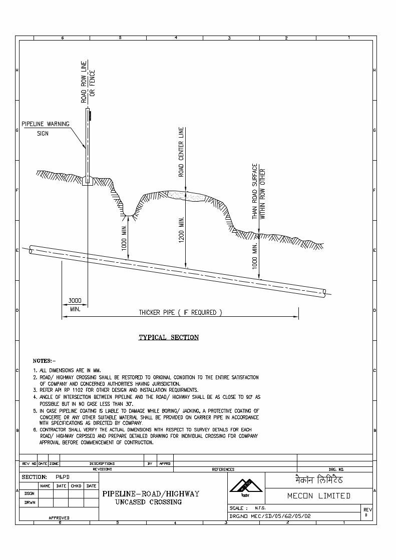
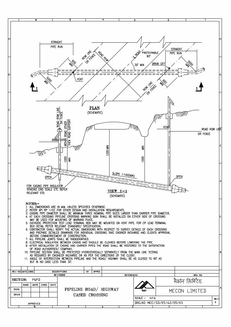
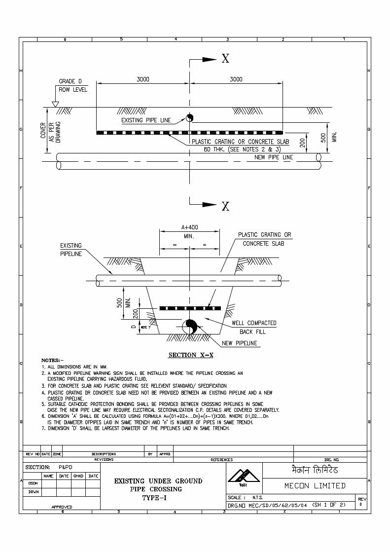
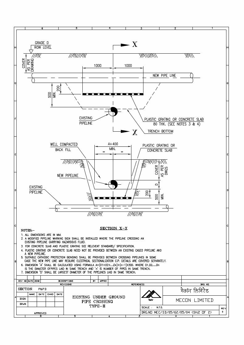
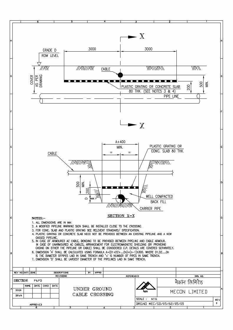
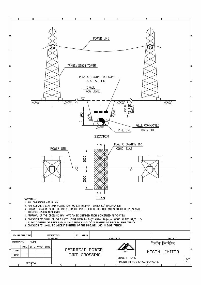
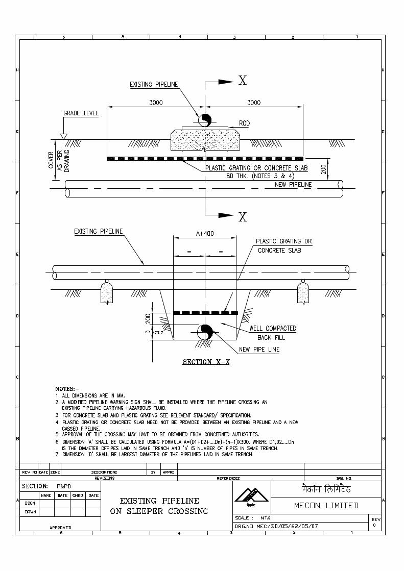
SPECIFICATION FORPIPING FABRICATION AND ERECTION
SPECIFICATION NO. MEC/S/05/62/06
(PROCESS & PIPING DESIGN SECTION)MECON LIMITED
NEW DELHI 110 016
MECON LIMITEDREGD. OFF: RANCHI (BIHAR)
PROCESS & PIPINGDESIGN SECTION
NEW DELHI
STANDARD SPECIFICATION
TITLE PIPING FABRICATION ANDERECTION
SPECIFICATION NO. PAGE 1 OF 62
MEC/S/05/62/06 REVISION 0
C O N T E N T S
1.0 GENERAL
2.0 CODES OF PRACTICE
3.0 FABRICATION
4.0 WELDING
5.0 ERECTION
6.0 INSPECTION
7.0 PROTECTIVE COATING
8.0 FLUSHING
9.0 HYDROSTATIC TESTING
ANNEXURE-1ANNEXURE-2ANNEXURE-3ANNEXURE-4
PREPARED BY CHECKED BY APPROVED BY
MECON LIMITEDREGD. OFF: RANCHI (BIHAR)
PROCESS & PIPINGDESIGN SECTION
NEW DELHI
STANDARD SPECIFICATION
TITLE PIPING FABRICATION ANDERECTION
SPECIFICATION NO. PAGE 2 OF 62
MEC/S/05/62/06 REVISION 0
1.0 GENERAL
This specification covers the minimum technical requirements for the fabrication,erection and testing of piping systems in accordance with the requirements ofthis specification, approved drawings and as directed by COMPANY.
2.0 CODES OF PRACTICE
2.1 All phases of work pertaining to process lines handling Natural Gas shall becarried out in accordance with latest edition of ANSI B 31.8 "GASTRANSMISSION AND DISTRIBUTION PIPING SYSTEM" with modificationsand additions as specified in various sections of this specification.
2.2 All phases of work pertaining to utility lines shall be carried out in accordancewith the latest edition of ANSI B 31.3 "CODE FOR PRESSURE PIPING,PETROLEUM REFINERY PIPING" CONTRACTOR shall bear the cost ofrepair, modifications and replacements, if any, becoming necessary due to non-compliance of codes, this specification or due to disregard of COMPANY'sinstructions.
3.0 FABRICATION
3.1 All fabrication shall be carried out in accordance with piping generalarrangement drawings, (prepared by CONTRACTOR and approved byCOMPANY) including this specification and codes as specified in section 2.0.
3.2 CONTRACTOR shall be responsible for working to the exact dimensions as perthe approved drawings. Dimensional tolerances to be adopted duringimplementation of fabrication work shall be as per attached sketch"TOLERANCES FOR FABRICATION".
3.3 Flange bolt holes shall generally straddle the established centre lines unlessother orientation is required and as called out in approved drawings.
MECON LIMITEDREGD. OFF: RANCHI (BIHAR)
PROCESS & PIPINGDESIGN SECTION
NEW DELHI
STANDARD SPECIFICATION
TITLE PIPING FABRICATION ANDERECTION
SPECIFICATION NO. PAGE 3 OF 62
MEC/S/05/62/06 REVISION 0
3.4 Threading shall be NPT to ANSI B 1.20.1. Threading shall preferably be doneafter bending, forging or heat treatment operation. However if it is not possible,precaution shall be taken to protect threading against deformation. Thread shallbe clean cut with no burrs or stripping. Dies shall be new, sharp and properlydesigned for piping material. Ends shall be reamed to remove burrs.
3.5 All threaded joints shall be aligned properly. The pipe entering unions shall betrue to centrelines so as to avoid forcing of union coupling during make up.Damaged threads shall be cut from the end of run and the pipe shall berethreaded.
3.6 Immediately before testing the piping, all threads of pipe and fittings shall bethoroughly cleared of cuttings, fuel oil or other foreign matter. The male threadsshall be sealed with thread sealant and the piping made up sufficiently for thethread to seize. Sealant shall be teflon tape.
3.7 Seal welding of threaded connections when specified shall include the first blockvalve, cover all threads. The joint shall be cleaned of all cutting oil and otherforeign material and made up dry to full thread engagement. Instrumentthreaded connections which are frequently subjected to testing andmaintenance shall not be seal welded.
3.8 All threaded connections shall be protected from rusting by applying greases oroil when in operating condition.
3.9 When socket weld fittings or valves are used, pipe shall be spacedapproximately 1/16" to avoid bottoming which could result in excessive weldstress.
3.10 Where the ends of the piping components being welded have an internalsurface misalignment exceeding 1.6mm, the wall of the component extendinginternally shall be trimmed by machining so that the adjoining internal surfacewill approximately flush.
3.11 Laying, Cutting and Fitting up
Extensive use of templates, gauges, plumb lines shall be made for laying,cutting and fitting up of various piping components for fabrication.
MECON LIMITEDREGD. OFF: RANCHI (BIHAR)
PROCESS & PIPINGDESIGN SECTION
NEW DELHI
STANDARD SPECIFICATION
TITLE PIPING FABRICATION ANDERECTION
SPECIFICATION NO. PAGE 4 OF 62
MEC/S/05/62/06 REVISION 0
3.12 Pipe joints shall be accomplished by butt welding for pipe sizes 2" and aboveand by screwed coupling for pipes 1½" and below with the exception for utilitiespiping which shall have socket weld coupling for size upto 1½".
3.13 Edge preparation for butt weld joints shall conform to ANSI B 16.25. Cutting ofedges shall preferably be done by machine.
3.14 Pipe bends for piping system below 1½" NB shall be used when called for inapproved arrangement drawings. Cold bending will be implemented with specialbending tools with guides to avoid flattening. The minimum radius allowed shallnot be less than five times the outside diameter of pipe. CONTRACTOR shallobtain COMPANY's approval of bending tool to be used.
3.15 All branch connection shall be joined to header with full penetration weld.Reinforcement pads where required shall be added only after external andinternal visual inspection of the attachment. Re-inforcement pad shall beprovided with ¼" tapped weep hole. Weep holes shall be plugged.
3.16 On completion of both shop and field fabrication, all sub-assemblies shall becleaned from the inside and outside by suitable mechanical means ensuring thatthey are free from all loose foreign materials such as scales, sand, weldspatters, oil, grease, cutting chips etc.
4.0 WELDING
Welding of pipelines shall be done as per applicable codes and Annexure-1
5.0 ERECTION
5.1 Pre-fabrication and Field Assembly
Extent of pre-fabrication shall be purely at the discretion of CONTRACTORkeeping in view the following :-
5.1.1 Field joint shall be decided by CONTRACTOR keeping in view the transportationof pre-fabricated pieces to site.
MECON LIMITEDREGD. OFF: RANCHI (BIHAR)
PROCESS & PIPINGDESIGN SECTION
NEW DELHI
STANDARD SPECIFICATION
TITLE PIPING FABRICATION ANDERECTION
SPECIFICATION NO. PAGE 5 OF 62
MEC/S/05/62/06 REVISION 0
5.1.2 There can be some variations in the dimensions and level appearing in thearrangement drawings and those actually occurring at site due to minorvariations in the location of equipments, structures, cut out etc. Adequate fieldjoints shall be provided, permitting assembly and erection of pipe work withoutmajor modification.
5.2 Supporting
Location and design of pipe supports shown in approved drawings and supportdrawings shall be strictly followed.
5.2.1 Supports shall be installed in such a way that they do not contribute to overstressing of a line.
5.2.2 Fabrication and erection of additional supporting elements and structural fixtureswhich in COMPANY's view are required for proper supporting of the system,shall be carried out by CONTRACTOR at no extra cost.
5.2.3 All temporary supports, elements required for alignment, erection and assemblyshall be removed after completion of work.
5.3 Equipment hook-up
5.3.1 Prior to hook-up, the alignment and trueness of flange faces shall be checked toensure that no undue stresses shall be induced in the system while hooking up.
6.0 INSPECTION
6.1
6.2 CONTRACTOR shall provide all facilities/ assistance to COMPANY for properexecution of their inspection without any extra charge.
6.3 All piping work shall be subjected to inspection by COMPANY at any time duringfabrication. CONTRACTOR shall furnish to COMPANY detailed workprogramme sufficiently in advance, in order to enable COMPANY to arrange forinspection.
MECON LIMITEDREGD. OFF: RANCHI (BIHAR)
PROCESS & PIPINGDESIGN SECTION
NEW DELHI
STANDARD SPECIFICATION
TITLE PIPING FABRICATION ANDERECTION
SPECIFICATION NO. PAGE 6 OF 62
MEC/S/05/62/06 REVISION 0
7.0 PROTECTIVE COATING
7.1 All above ground piping system shall be applied with protective coating inaccordance with specification for shop & field painting.
7.2 All under ground portion of piping system shall be coated with three layer P.E.coating. CONTRACTOR shall prepared procedure for epoxy painting of burriedpipeline for approval of COMPANY. Procedure shall include surface preparation,brand and type of coating to be adopted. Coating of pipes shall not commencewithout approval of coating procedure. Total dry film thickness to be achievedshall not be less than 300 microns. Compatible primer and finish coat asrecommended by coating manufacturer shall only be applied. Coating integrityshall be checked by "Holiday detector" over full length of coated pipe work.Coating to be supplied by CONTRACTOR shall be suitable for designtemperature.
7.3 Once the coating has been accepted by COMPANY, backfiling operation can bestarted. In order to protect coated pipe from damage, the excavated trench shallbe examined for stone, rock and any other hard substance detrimental tocoating. All such substances shall be removed before lowering the pipe in thetrench. COMPANY may ask for a 100mm padding of clear sand under andabove pipeline in rocky or otherwise hard soil area. No additional payment onaccount of padding shall however be admissible.
8.0 FLUSHING
Completed piping systems shall be flushed by CONTRACTOR with fresh water,to clean the pipe of all dirt, debris, and foreign material. CONTRACTOR shallprepare a procedure for flushing of the system for approval of COMPANY.Flushing shall not be commenced without approval of flushing procedure.
8.1 CONTRACTOR shall perform all activities like dismantling and reinstalling of allstrainers, in line instruments etc. before and after completion of flushing.
8.2 Flushing shall be considered as complete only after inspection and approval byCOMPANY.
MECON LIMITEDREGD. OFF: RANCHI (BIHAR)
PROCESS & PIPINGDESIGN SECTION
NEW DELHI
STANDARD SPECIFICATION
TITLE PIPING FABRICATION ANDERECTION
SPECIFICATION NO. PAGE 5 OF 62
MEC/S/05/62/06 REVISION 0
8.3 Disposal of muck and flushing media shall be arranged by CONTRACTOR asdirected by COMPANY, in such a manner that it does not spoil the adjacentinstallation. CONTRACTOR shall obtain COMPANY approval regarding theplace and method to be adopted for disposal of debris.
8.4 Record of flushing giving following details shall be submitted by CONTRACTORto COMPANY for its approval and records :
a) Date of flushing
b) Identification of line : flushed-line number
9.0 HYDROSTATIC TESTING
9.1 Completed piping system as approved by COMPANY shall be hydrostaticallytested in the presence of COMPANY. The general requirements of hydrostatictesting shall be in accordance with codes specified in section 2.0.
9.2 CONTRACTOR shall prepare hydrostatic test procedure based on specifiedcodes. The hydrostatic test shall commence only after approval of procedure byCOMPANY.
9.3 Piping system shall be hydrostatically tested to a pressure corresponding to 1.4times the design pressure.
9.4 Fresh water shall be used as test media. CONTRACTOR shall locate the sourceof water supply and arrange for transportation of water to test site.CONTRACTOR shall arrange at his own cost the water analysis and confirmthat water is suitable for testing. In case any corrosion inhibitor is to added, thesame shall be done after approval of COMPANY.
9.5 Lines repaired subsequent to hydrostatic test shall be retested using the sameprocedure as originally adopted. However COMPANY may waive such retest incase of minor repairs by taking precautionary measures to ensure soundconstruction.
9.6 All equipment and instruments used for hydrostatic test shall be approved byCOMPANY before start of tests.
MECON LIMITEDREGD. OFF: RANCHI (BIHAR)
PROCESS & PIPINGDESIGN SECTION
NEW DELHI
STANDARD SPECIFICATION
TITLE PIPING FABRICATION ANDERECTION
SPECIFICATION NO. PAGE 8 OF 62
MEC/S/05/62/06 REVISION 0
9.7 Pressure gauges shall be installed on line to measure test pressures. In case oflonger lines two or more pressure gauges shall be installed as directed byCOMPANY. One gauge shall be installed at the discharge of the pressurisingpump. Pressure gauge used for hydrostatic testing shall be calibrated with deadweight tester in the presence of Engineer-in-charge. Range of pressure gaugeshall generally be 1.5 times the test pressure.
9.8 Orifice plates and restriction orifices shall not be installed until hydrostatic testingis completed. Temporary gaskets shall be used during testing.
9.9 First block valve of pressure instruments shall be half open & plugged at thetime of hydrostatic testing. Temperature connections shall be blanked off duringtesting.
9.10 All equipments, in line instruments, relief valves shall be disconnected frompiping system by means of blinds during testing. Control valves shall bereplaced by spool pieces during testing.
9.11 High point vents and low point drain required for testing in addition to thosemarked in the drawings shall be provided by CONTRACTOR at his own cost.
9.12 All welded and screwed joints shall be kept clean for detecting leaks duringtesting.
9.13 Test pressure shall be maintained long enough to facilitate complete inspectionof the system. Minimum duration of test shall be 6 hours unless other wisespecified. Pressurising equipment shall be isolated immediately after testpressure is attained.
9.14 After successful completion of hydrostatic testing, the piping system shall bedewatered. All lines shall be completely dried using compressed air.CONTRACTOR shall make his own arrangement for supply of compressed air.Drying of lines shall be considered complete on approval by COMPANY.
MECON LIMITEDREGD. OFF: RANCHI (BIHAR)
PROCESS & PIPINGDESIGN SECTION
NEW DELHI
STANDARD SPECIFICATION
TITLE PIPING FABRICATION ANDERECTION
SPECIFICATION NO. PAGE 9 OF 62
MEC/S/05/62/06 REVISION 0
9.15 Test Records
The records in duplicate shall be prepared and submitted by CONTRACTOR asbelow :
a) Date of test
b) Identification of pipe tested - line number
c) Test pressure
d) Test results
e) Signature of CONTRACTOR
f) Approval signature by COMPANY.
MECON LIMITEDREGD. OFF: RANCHI (BIHAR)
PROCESS & PIPINGDESIGN SECTION
NEW DELHI
STANDARD SPECIFICATION
TITLE PIPING FABRICATION ANDERECTION
SPECIFICATION NO. PAGE 10 OF 62
MEC/S/05/62/06 REVISION 0
ANNEXURE-1
WELDING SPECIFICATION
10.0 GENERAL
This specification shall be followed for the fabrication of all types of welded jointsof carbon steel above ground natural gas service piping systems.
The welded pipe joints shall include the following :
a) All line pipe joints of the longitudinal and circumferential butt welded.
b) Attachments of castings, forgings, flanges.
c) Welded manifold headers and other sub-assemblies
d) Welded branch connections with or without reinforcing pads.
e) Joints in welded/ fabrication piping components.
f) The attachments of smaller connections for vents drain drips and otherinstrument tappings.
Any approval granted by the Engineer-in-charge or owner's inspectors shall notrelieve the contractor of his responsibilities & guarantees.
1.1 Applicable Codes & Standards
All welding work, equipments for welding, heat treatment, other auxiliaryfunctions and the welding personnel shall be as per the requirements of thelatest editions of the following approved standards and procedures :-
i) Code for gas transmission and distribution piping systems. ANSI B31.8.
ii) Code for petroleum refinery piping, ANSI B31.3.
MECON LIMITEDREGD. OFF: RANCHI (BIHAR)
PROCESS & PIPINGDESIGN SECTION
NEW DELHI
STANDARD SPECIFICATION
TITLE PIPING FABRICATION ANDERECTION
SPECIFICATION NO. PAGE 11 OF 62
MEC/S/05/62/06 REVISION 0
In addition, the following codes/ specifications referred to in the relevant code offabrication shall be followed for the welding/ brazing qualifications, consumablequalifications and non destructive test procedures.
i) Standard for welding of pipelines and related facilities API-1104.
ii) Material Specifications - Welding rods, electrodes and fillermaterials - ASME Sec. - IIC.
iii) Code for non destructive examination ASME Sec-V.
iv) Qualification standard for welding and brazing procedure andwelders, brazers, welding and brazing operators - ASME Sec-I
In the event of any difference due to the additional requirements mentioned inthis specification, over and above those obligation as per codes, thisspecification shall be binding.
1.2 Base Material
a) In general carbon steel is used in this plant. The details of materialspecifications are given in the welding Specification Chart.
b) The contractor shall provide the Manufacturer's test certificates for everyheat of the materials supplied by him.
1.3 Filler Materials
a) The Contractor shall provide all the necessary welding electrodes, fillermaterials, etc. required for the execution of the work.
b) The welding electrodes/ filler wires supplied by the Contractor shallconform to the class specified in the welding specification chart. Thematerials shall be of the make approved by the Engineer-in-charge.
MECON LIMITEDREGD. OFF: RANCHI (BIHAR)
PROCESS & PIPINGDESIGN SECTION
NEW DELHI
STANDARD SPECIFICATION
TITLE PIPING FABRICATION ANDERECTION
SPECIFICATION NO. PAGE 12 OF 62
MEC/S/05/62/06 REVISION 0
c) The electrode shall be suitable for the welding process recommendedand base metal used. Unless otherwise specified physical properties ofthe welds produced by a electrode recommended for the welding of aparticular base metal shall not be lower than the minimum valvesspecified for the base metal and shall correspond to the physicalproperties of the class of electrode adopted. The choice of electrode shallbe made after conducting the required tests on the electrodes as perrelevant standards, and shall be the sole prerogative of the Engineer-in-charge.
d) Electrode qualification test records should be submitted as per theExhibit-A (attached) in respect of the electrodes tested by the contractor,for obtaining the approval of the Engineer-in-charge.
e) The Contractor shall submit batch test certificate from the electrodeManufacturers giving details of physical and chemical tests carried out bythem, for each batch of electrodes to be used.
f) All electrodes shall be purchased in sealed containers and storedproperly to prevent deterioration. The electrodes removed from thecontainers shall be kept in holding ovens at temperature recommendedby the electrode Manufacture. Out-of-the oven time of electrodes beforethey are consumed shall not exceed the limits recommended by theelectrodes manufacturer. The electrodes shall be handled with care toavoid any damage to flux covering.
g) All low hydrogen type of electrodes shall be rebaked at 350°C for 1 hourminimum and stored in ovens kept at 80-100°C before use.Recommendations of the electrode Manufacturer shall be followed ifavailable.
h) The electrodes, filler wires and flux used shall be free from rust, oil,greases, earth and other foreign matter which can affect the quality ofwelding.
1.4 Welding Consumables
The Contractor shall provide at this own expense all the weldingconsumables necessary for the execution of the job such as electrodesfiller wires, oxygen, acetylene, etc. and these should bear the approval ofthe COMPANY.
MECON LIMITEDREGD. OFF: RANCHI (BIHAR)
PROCESS & PIPINGDESIGN SECTION
NEW DELHI
STANDARD SPECIFICATION
TITLE PIPING FABRICATION ANDERECTION
SPECIFICATION NO. PAGE 13 OF 62
MEC/S/05/62/06 REVISION 0
1.5 Equipment & Accessories
1.5.1 The Contractor should have the arrangement of sufficient number of weldingand cutting equipments, auxiliaries and accessories of sufficient capacities so asto meet the target schedule.
1.5.2 All the equipment for performing the heat treatment, including transformers,thermocouples, flow meters, automatic temperature recorders with suitablecalibration arrangement etc. shall be provided by the Contractor, at his ownexpense and these should bear the approval of the COMPANY.
1.5.3 Contractor shall make necessary arrangements at his own expense for providingthe radiographic equipment, radiographic films, and all the equipment/ materialsrequired for carrying out the dye penetrant/ magnetic particle test for satisfactoryand timely completion of the job.
1.5.4 Redoing of any work necessitated by faulty equipments or operation used by theContractor, will be done at his own expense.
1.6 Welding Processes
1.6.1 Welding of various materials under this specification shall be carried out usingShielded Metal Arc Welding (SMAW) Process with the approval of the Engineer-in-charge.
1.6.2 The welding processes to be employed are given in the welding specificationchart. Any deviation desired by the Contractor shall be obtained through theexpress consent of the Engineer-in-charge.
1.6.3 Automatic and semi-automatic welding processes shall be employed only withthe express approval of the Engineer-in-charge. The welding procedure adoptedand consumables used shall be specifically approved.
1.6.4 A combination of different welding processes or a could be employed for aparticular joint only after duly qualifying the welding procedure as per therequirements of code of fabrication to be adopted and obtaining the approval ofthe Engineer-in-charge.
MECON LIMITEDREGD. OFF: RANCHI (BIHAR)
PROCESS & PIPINGDESIGN SECTION
NEW DELHI
STANDARD SPECIFICATION
TITLE PIPING FABRICATION ANDERECTION
SPECIFICATION NO. PAGE 14 OF 62
MEC/S/05/62/06 REVISION 0
1.7 End Preparation
1.7.1 End Preparation
The edges to be welded shall be prepared to meet the joint design requirementsby gas cutting, machining or grinding method. After gas cutting, oxides shall beremoved by chipping or grinding.
1.7.2 Cleaning
The ends to be welded shall be properly cleaned to remove paint, oil, greases,rust, oxides, sand, earth and other foreign matter. The ends shall be completelydry before the welding commences.
1.8 Alignment and Spacing
Prior to alignment, the contractor shall inspect the pipe ends inside and outsidefor damage, dents, laminations etc. Pipe for welding shall be set up correctlyspaced. Temporary attachment of any kind shall not be welded. Every effortshall be made to reduce misalignment by the use of clamp and rotation of pipesto the best fit. For pipes of same nominal wall thickness, the off set should notexceed 1.6mm. Any branch connections sleeve shall be at least 150mm fromany other weld. The welds for fitting shall be so located that top of the weld shallnot come within 50mm of any other weld. The use of internal line up clamps ismandatory for diameters 10" and above. However, in case where it is impossibleto use internal line up clamp, external line up clamp may be used.
1.9 Weather Conditions
1.9.1 The parts being welded and the welding personnel should be protected fromrain and strong winds. In the absence of such a protection no welding shall becarried out.
1.10 Welding
1.10.1 Root Pass
a) Root pass shall be made with electrodes/ filler wires recommended in thewelding specification chart. The preferable size of the electrode is 2.5mmdiameter (12 SWG) but in no case greater than 3.25mm (10 SWG).

MECON LIMITEDREGD. OFF: RANCHI (BIHAR)
PROCESS & PIPINGDESIGN SECTION
NEW DELHI
STANDARD SPECIFICATION
TITLE PIPING FABRICATION ANDERECTION
SPECIFICATION NO. PAGE 15 OF 62
MEC/S/05/62/06 REVISION 0
b) Uphill welding shall be adopted for welding pipes weld fixed with its axishorizontal. Downward technique of welding shall not be used for weldingof pipes in horizontal position, unless specifically permitted by Engineer-in-charge for a particular case.
c) The root pass of but joints should be executed properly so as to achievefull penetration with complete fusion of the root edges. Weld projectioninside the pipe shall not exceed .4mm wherever not specified by theapplicable code.
d) Any deviations desired from the recommended welding technique andelectrodes indicated in the welding specification chart should be adoptedonly after obtaining express approval of the Engineer-in-charge.
e) Welding shall be continuous & uninterrupted during a pass.
f) On completion of each run, craters, welding irregularities, slag etc., shallbe removed by grinding and chiselling.
g) While the welding is in progress care should be taken to avoid any kind ofmovement of components, to prevent occurrence of weld cracks.
h) Fillet welds shall be made by shielded metal arc/ GTAW welding processirrespective of the thickness and class of piping.
i) Peening shall not be used unless specified in the welding specificationchart.
1.10.2 Joint Completion
a) Joint shall be completed using the class of filler wires/ electrodes,recommended in the welding specification chart.
b) Two weld beads shall not be started at the same point in different layers.
b) Butt joints shall be completed with a cover layer that would effect goodcover at the joint edge and a gradual notch free surface.
MECON LIMITEDREGD. OFF: RANCHI (BIHAR)
PROCESS & PIPINGDESIGN SECTION
NEW DELHI
STANDARD SPECIFICATION
TITLE PIPING FABRICATION ANDERECTION
SPECIFICATION NO. PAGE 16 OF 62
MEC/S/05/62/06 REVISION 0
d) Each weld joints should have a workman like finish.
e) Weld identification mark shall be stamped clearly at each joint, justadjacent to the weld. Metal stamping shall not be used on the thin wallpipe. Suitable paint shall be used on thin wall pipes for identification.
f) No painting shall be done until the weld joint has been hydrostaticallytested.
1.11 Heat Treatment
1.11.1 Preheating
a) Preheating requirements for the various materials shall be as per thewelding specification chart attached.
b) Preheating shall be performed using resistance or induction heatingmethods. Preheating by gas burners, utilising any acetylene or oxy-propane gas mixtures, with neutral flame may also be carried out whenpermitted by the Engineer-in-charge.
c) Preheating shall extend uniformly to atleast three times the thickness ofthe joint, but not less than 100mm, on both sides of the weld.
d) Preheating temperature shall be maintained over the whole length of thejoint during welding. Temperature indicating crayons or other temperatureindicating devices shall be provided by the contractor to check thetemperature.
1.11.2 Postweld Heat Treatment
a) Post weld heat treatment, wherever required for joints between pipes,pipes an fittings, pipe body and supports shall be carried out as per therelevant specifications, applicable standards and the instructions of theEngineer-in-charge.
c) The heat treatment of welded joints shall be carried out as per therequirements laid down in ANSI B31.8 and welding specification chart.
MECON LIMITEDREGD. OFF: RANCHI (BIHAR)
PROCESS & PIPINGDESIGN SECTION
NEW DELHI
STANDARD SPECIFICATION
TITLE PIPING FABRICATION ANDERECTION
SPECIFICATION NO. PAGE 17 OF 62
MEC/S/05/62/06 REVISION 0
c) The contractor shall submit for the approval of the Engineer-in-charge, the details of the post weld heat treatment procedure, as per Exhibit `B'attached, that the propose to adopt for each of the materials/ assembly/part involved, well before carrying out actual heat treatment.
d) Post weld heat treatment shall be done by using an electric resistance orinduction heating equipment as decided by the Engineer-in-charge.
e) While carrying out local post weld heat treatment, technique ofapplication of heat must ensure uniform temperature attainment at allpoints of the portion being heat treated. Care shall be taken to ensurethat width of treated band over which specified post weld heat treatmentis carried out, the temperature attained is atleast as that specified in therelevant applicable standards/ codes.
f) Throughout the cycle of heat treatment, the portion outside the heatedband shall be suitably wrapped under insulation so as to avoid anyharmful temperature gradient at the exposed surface of pipe. For thispurpose temperature at the exposed surface of the pipes should not beallowed to exceed 400°C.
g) The temperature attained by the portion under heat treatment shall berecorded by means of thermocouple pyrometers. Adequate number ofthermocouples should be attached to the pipe directly at the equallyspaced location along the periphery of the pipe joint. The minimumnumber of thermocouples attached per joint shall be 1 upto 6" dia, 2 upto10" dia and 3 upto 12" and above. However the Engineer-in-charge canincrease the required minimum number of thermocouples to be attachedif found necessary.
h) Automatic temperature recorders which have been duly calibrated shouldbe employed. The calibration chart of each recorder should be submittedto the Engineer-in-charge prior to starting the heat treatment operationand his approval should be obtained.
i) Immediately on completion of the heat treatment, the post weld heattreatment charts/ records alongwith the hardness test results on the weldjoints (whenever required as per the welding specification chart), shall besubmitted to Engineer-in-charge for his approval.
MECON LIMITEDREGD. OFF: RANCHI (BIHAR)
PROCESS & PIPINGDESIGN SECTION
NEW DELHI
STANDARD SPECIFICATION
TITLE PIPING FABRICATION ANDERECTION
SPECIFICATION NO. PAGE 18 OF 62
MEC/S/05/62/06 REVISION 0
j) Each joint shall bear an identification number which shall be maintainedin the piping sketch to be prepared by the contractor. The jointidentification number should appear on the corresponding post weld heattreatment charts. The same identification numbers shall also be followedfor identification for corresponding radiographic films. The chartcontaining the identification numbers and piping sketch shall besubmitted to the Engineer-in-charge in suitable folders.
k) The hardness of the heat affected zone as well as of the weld metal, afterheat treatment, shall be measured using suitable hardness tester andshall not exceed the maximum hardness specified in the weldingspecification chart. The weld joint shall be subjected to re-heat treatmentwhen hardness measured exceeds the specified limit, at the contractor'sown expenses.
l) The contractor shall arrange for the hardness testing and shall maintainthe records of all joints tested. These records shall be checked by theplant Owner's inspector.
1.12 Cleaning of the Weld Joints
All weld joints shall be free from adherent weld spatter, slag, dirt or foreignmatter. This can be achieved by brushing.
1.13 Inspection & Testing
1.13.1 General
a) The owner's inspector shall have free access to all concerned areas,where the actual work is being performed. The contractor shall also offerthe Owner's inspector all means and facilities necessary for carrying outinspection.
b) The owner is entitled to depute his own inspector to the shop or fieldwhere pre-fabrication and erection of pipelines are being done with (butnot limited to) the following objectives :-
i. To check the conformance to relevant standards and suitability ofvarious welding equipments and the welding performance.
MECON LIMITEDREGD. OFF: RANCHI (BIHAR)
PROCESS & PIPINGDESIGN SECTION
NEW DELHI
STANDARD SPECIFICATION
TITLE PIPING FABRICATION ANDERECTION
SPECIFICATION NO. PAGE 19 OF 62
MEC/S/05/62/06 REVISION 0
ii. To supervise the welding procedure qualification.
iii. To supervise the welder performance qualifications.
c) Contractor shall intimate sufficiently in advance the commencement ofqualification tests welding works and acceptance tests, to enable theplant owner's inspector to be present to supervise them.
1.13.2 Welding Procedure Qualifications
a) Welding Procedure Qualification shall be carried out in accordance withthe relevant requirements of API 1104/ ASME Sec-IX or other applicablecodes and other job requirements by the contractor at his expense. Thecontractor shall submit the welding procedure specifications in format asper Exhibit-C (attached) immediately after the receipt of the order.
b) COMPANY's inspector will review, check and approve the weldingprocedure submitted and shall release the procedure for procedurequalification tests. The procedure qualification test shall be carried out bythe Contractor under field conditions at this own expense. A complete setof test results in format as per Exhibit-D (attached) shall be submitted tothe COMPANY's inspector for approval immediately after completing theprocedure qualification test and atleast 2 weeks before thecommencement of actual work. Standard tests as specified in the codeshall be carried out in all cases. In addition to these tests, other tests likeradiography, macro/ micro examination, hardness testers, dye penetrantexamination, Charpy V-notch etc. shall be carried out on specimens. Itshall be the responsibility of the contractor to carry out all the testsrequired to the satisfaction of the COMPANY's Inspector. The destructivetesting of welded joints shall be as per Annexure-2 and ASME Sec-IX.
MECON LIMITEDREGD. OFF: RANCHI (BIHAR)
PROCESS & PIPINGDESIGN SECTION
NEW DELHI
STANDARD SPECIFICATION
TITLE PIPING FABRICATION ANDERECTION
SPECIFICATION NO. PAGE 20 OF 62
MEC/S/05/62/06 REVISION 0
1.13.3 Welder's Qualification
a) Welders shall be qualified in accordance with the API 1104/ ASME IXand other applicable codes by the contractor at his expense. The buttweld test pieces of the qualification test shall meet the radiographic testsrequirements as mentioned in this specification. The COMPANY'sinspector shall witness the test and certify the qualification of each welderseparately. Only those welders who have been approved by theCOMPANY's inspector shall be employed for welding. Contractor shallsubmit the welder qualification test reports in the standard format andobtain express approval, before commencement of the work. It shall bethe responsibility of contractor to carry out Qualification tests of welders.
b) The welders shall always have in their possession the identification cardas shown in Exhibit-E and shall produce it on demand by theCOMPANY's Inspector. It shall be the responsibility, of the Contractor toissue the identify cards after it has been duly certified by the COMPANY.If a welder is found to perform a type of welding for which he is notqualified, he shall be debarred from doing any further work. All weldsperformed by an unqualified welder shall be cut and redone by a qualifiedwelder at the expense of the Contractor.
1.13.4 Visual Inspection
Inspection of all welds shall be carried out by COMPANY as per the latesteditions of the applicable codes and specifications. All finished welds shall bevisually inspected for parallel and axial alignment of the work, excessivereinforcement, concavity of welds, shrinkage, cracks, under cuts, dimensions ofthe weld, surface porosity and other surface defects. Under-cutting adjacent tothe completed weld shall not exceed the limits specified in the applicablestandard/ code.
1.13.5 Non-destructive Examination
The non destructive examination shall mainly consist of examination using x-rayradiography as detailed in Annexure-4.
MECON LIMITEDREGD. OFF: RANCHI (BIHAR)
PROCESS & PIPINGDESIGN SECTION
NEW DELHI
STANDARD SPECIFICATION
TITLE PIPING FABRICATION ANDERECTION
SPECIFICATION NO. PAGE 21 OF 62
MEC/S/05/62/06 REVISION 0
Radiographic examination of one hundred percent (100%) girth welds will berequired by the COMPANY. Welds shall meet the standards of acceptability asset forth in API 1104 and as per the requirements laid in subsequentparagraphs.
The CONTRACTOR shall make all the arrangements for the radiographicexamination of work covered by this specification at his expense.
The COMPANY will review all the radiographs of welds and inform theCONTRACTOR regarding unacceptable welds. The decision of the COMPANYshall be final and binding in this regard.
All requirements mentioned in the specification shall be arranged and executedby the CONTRACTOR through his own resources. In addition, for pipes withwall thickness 9.5mm and above, ultrasonic inspection is required in thefollowing cases as per Annexure-3 of this specification.
a) On the first 100 welded joints corresponding to each automatic (GTAW/GMAW) welding procedure used.
b) When 20mm or more are cut from the pipe end as supplied, the endsshall be ultrasonically inspected for an additional length of 20mm toensure no lamination exist.
c) When welds are repaired.
d) When in the opinion of COMPANY, ultrasonic inspection is required toconfirm or clarify defects indicated by radiography.
e) When automatic procedure is used at least 10cm on each weld shall beultrasonically inspected at COMPANY's discretion.
In addition, ultrasonic inspection may be required for certain critical weldings ofthe pipeline (i.e. tie-ins, welding of valves, flanges) randomly selected atCOMPANY's discretion. All fillet and groove welds other than that radiographedshall be subjected to dye pentrant/ MP inspection. The non destructive testsystem used for inspecting welds must be approved by the COMPANY.
Weld quality is judged on the basis of the acceptability criteria mentioned below :
MECON LIMITEDREGD. OFF: RANCHI (BIHAR)
PROCESS & PIPINGDESIGN SECTION
NEW DELHI
STANDARD SPECIFICATION
TITLE PIPING FABRICATION ANDERECTION
SPECIFICATION NO. PAGE 22 OF 62
MEC/S/05/62/06 REVISION 0
Any weld which as a result of radiographic and / or ultrasonic examination in theopinion of COMPANY exhibits imperfections greater than the limits stated inAPI-1104 latest edition or as superseded in this article shall be considereddefective and shall so be marked with an identification paint marker.
In addition to the API-1104 requirements, the welds containing cracks includingcrater cracks regardless of size of location are unacceptable.
i. Any amount of inadequate penetration of the root bead as defined byAPI-1104 is unacceptable.
ii. Any amount of incomplete fusion between the root and bevel as definedby API-1104 is unacceptable.
iii. Unrepaired burn through areas are unacceptable.
The contractor shall be responsible for carrying out radiography, rectification ofdefects and reradiography of weld rectified/ repaired.
• The extent of radiography shall be as per specifications to be supplied tothe Contractor. For welds between dissimilar materials, the extent ofradiographic examination shall be more stringent for the tworecommended materials being welded.
• Radiographic examination shall be carried out using x-radiation. Gammaray sources may be used in place of X-ray with the approval of the EIC incase of inaccessible joints.
• The contractor shall fulfill all the statutory safety requirements whilehandling x-ray and Gamma ray equipments.
• The Contractor shall furnish all films to the Owner's inspector immediatelyafter processing. The details of the radiographs alongwith the jointidentification number shall be duly entered in a register and signed by theContractor and shall be submitted to the Owner's inspector for approval.
• The contractor shall provide the inspector all necessary facilities at sitesuch as a dark room with controlled temperature, film viewer etc. toenable him to examine the radiographs.
MECON LIMITEDREGD. OFF: RANCHI (BIHAR)
PROCESS & PIPINGDESIGN SECTION
NEW DELHI
STANDARD SPECIFICATION
TITLE PIPING FABRICATION ANDERECTION
SPECIFICATION NO. PAGE 23 OF 62
MEC/S/05/62/06 REVISION 0
1.13.6 Magnetic Particle & Liquid Penetrant Examination
a) Whenever such tests are specified, the tests shall be carried out on jointschosen by the Owner's Inspector.
1.13.7 Hardness Test
Hardness requirement of welds shall be as per welding specification chart.Hardness testing may be carried out by Vickers, Brinell or Poldy Hardness testeras agreed by the Owner's Inspector.
1.13.8 Proof Tests
Hydrostatic and pneumatic tests shall be performed as per the requirements laiddown in the respective flushing & testing specification/ applicable codes todemonstrate the soundness of the welds. The tests shall be conducted onlyafter fulfilling the requirements of visual examination, radiography etc. and afterthe entire work has been certified by the Owner's inspector, as fit for subjectingto such test.
1.14 Repairs of Welds
a) Defects ascertained, through the inspection methods, which are beyondacceptable limits shall be removed from the joint completely by theprocess of chipping and grinding.
b) When an entire joint is judged unacceptable, the welding shall becompletely cut and the edges be suitably prepared as per requiredalignment tolerances. The welded joint shall again be examined followingstandard practices.
c) No repair shall be carried out without prior permission of the Owner'sinspector.
d) Where random radiography is specified, the test welds of each weldershall be completely radiographed. In the case of pipes of sizes 6" andbelow, the first two welds shall be completely radiographed.
MECON LIMITEDREGD. OFF: RANCHI (BIHAR)
PROCESS & PIPINGDESIGN SECTION
NEW DELHI
STANDARD SPECIFICATION
TITLE PIPING FABRICATION ANDERECTION
SPECIFICATION NO. PAGE 24 OF 62
MEC/S/05/62/06 REVISION 0
e) For each weld found unacceptable due to a welder's fault, two additionalchecks should be carried out on welds performed by the same welder.This operation is interactive and the procedure of radiographing twoadditional welds for each weld deemed unsatisfactory shall be continuedtill such time that the two consecutive welds of satisfactory quality arefound for every defective weld.
The contractor shall carry out these additional radiographic testing.
To avoid the possibility of too many defective welds by a single welderremaining undetected for a long period of time, the Contractor shallpromptly arrange for radiographic examination so that there is noaccumulation of defective joints.
1.15 Limitations on Repairs
Only one attempt at repair of any region is permitted. Repairs are limited to amaximum 30% of the weld length. For internal or external repairs which openthe weld root, only 20% of the weld length may be repaired. Repairs opening theroot must only be carried out in the presence of COMPANY. The minimumlength of a repaired area shall be 100mm as measured over the recappedlength. Welds containing cracks shall be cut out and rebevelled to make a joint,COMPANY shall authorise all repairs.
1.16 Weld Rejected by Accumulation of Defects
Where a weld is rejected by the accumulation of defect clause, as defined byAPI-1104 and this specification, repairs within these limitations are permitted.Defects in the filling and capping passes shall be repaired preferentially.
1.17 Documents to be submitted by the Contractor
a) Welding procedure specifications as per Exhibit-C immediately afterreceipt of the order.
b) Welding procedure qualification records as per Exhibit-D.
d) Welder performance qualification records as per Exhibit-C&Dimmediately after conducting welder qualification tests.
MECON LIMITEDREGD. OFF: RANCHI (BIHAR)
PROCESS & PIPINGDESIGN SECTION
NEW DELHI
STANDARD SPECIFICATION
TITLE PIPING FABRICATION ANDERECTION
SPECIFICATION NO. PAGE 25 OF 62
MEC/S/05/62/06 REVISION 0
d) Proposed heat treatment procedure as per Exhibit-B.
e) Heat treatment charts and records alongwith the hardness test results.

MECON LIMITEDREGD. OFF: RANCHI (BIHAR)
PROCESS & PIPINGDESIGN SECTION
NEW DELHI
STANDARD SPECIFICATION
TITLE PIPING FABRICATION ANDERECTION
SPECIFICATION NO. PAGE 28 OF 62
MEC/S/05/62/06 REVISION 0
ANNEXURE-A
Sheet 1 of 4
ELECTRODE QUALIFICATIONS TEST RECORD
A : Tested at Date :(Site Name)
Test Period :
Manufacturer's Name :
Brand Name :
Batch Number & size Tested :
Classification & Code :
Intended for Welding in positions :
In combination with (if any) :
Code of Reference (used for testing) :
Special requirements (if any) :
B : All - Weld Tensile Test
Base Material used :
Pre-heat temperature :
Postweld Heat Treatment Details :
Visual Examination :
Radiographic Examination Results :
MECON LIMITEDREGD. OFF: RANCHI (BIHAR)
PROCESS & PIPINGDESIGN SECTION
NEW DELHI
STANDARD SPECIFICATION
TITLE PIPING FABRICATION ANDERECTION
SPECIFICATION NO. PAGE 27 OF 62
MEC/S/05/62/06 REVISION 0
Sheet 2 of 4Tensile Test Results :
-------------------------------------------------------------------------------------------------------------------------Sl. Identification U.T.S. Yield Point Elongation RemarksNo. Number-------------------------------------------------------------------------------------------------------------------------
-------------------------------------------------------------------------------------------------------------------------
C : Impact Test Results
Test Temperature : Notch in :
Type of Specimens (Impd, Charpy: Size of Specimens :
-------------------------------------------------------------------------------------------------------------------------Specimen No. Impact Value Average-------------------------------------------------------------------------------------------------------------------------1.2.3.4.5.-------------------------------------------------------------------------------------------------------------------------
D : Chemical Analysis Result
Electrode size used :
Batch No.
-----------------------------------------------------------------------------------------------------------------%C %S %P %Si %Mn %Cr %Ni %Mo-----------------------------------------------------------------------------------------------------------------
-----------------------------------------------------------------------------------------------------------------
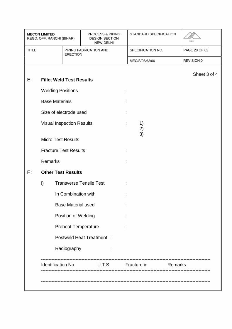
MECON LIMITEDREGD. OFF: RANCHI (BIHAR)
PROCESS & PIPINGDESIGN SECTION
NEW DELHI
STANDARD SPECIFICATION
TITLE PIPING FABRICATION ANDERECTION
SPECIFICATION NO. PAGE 28 OF 62
MEC/S/05/62/06 REVISION 0
Sheet 3 of 4E : Fillet Weld Test Results
Welding Positions :
Base Materials :
Size of electrode used :
Visual Inspection Results : 1)2)3)
Micro Test Results
Fracture Test Results :
Remarks :
F : Other Test Results
i) Transverse Tensile Test :
In Combination with :
Base Material used :
Position of Welding :
Preheat Temperature :
Postweld Heat Treatment :
Radiography :
-----------------------------------------------------------------------------------------------------------------Identification No. U.T.S. Fracture in Remarks-----------------------------------------------------------------------------------------------------------------
-----------------------------------------------------------------------------------------------------------------
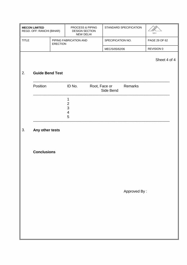
MECON LIMITEDREGD. OFF: RANCHI (BIHAR)
PROCESS & PIPINGDESIGN SECTION
NEW DELHI
STANDARD SPECIFICATION
TITLE PIPING FABRICATION ANDERECTION
SPECIFICATION NO. PAGE 29 OF 62
MEC/S/05/62/06 REVISION 0
Sheet 4 of 4
2. Guide Bend Test
-----------------------------------------------------------------------------------------------------------------Position ID No. Root, Face or Remarks
Side Bend-----------------------------------------------------------------------------------------------------------------
12345
-----------------------------------------------------------------------------------------------------------------
3. Any other tests
Conclusions
Approved By :
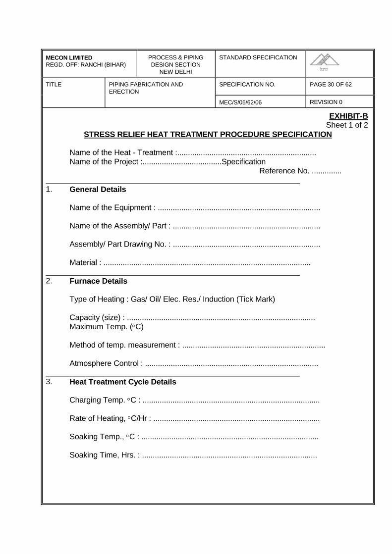
MECON LIMITEDREGD. OFF: RANCHI (BIHAR)
PROCESS & PIPINGDESIGN SECTION
NEW DELHI
STANDARD SPECIFICATION
TITLE PIPING FABRICATION ANDERECTION
SPECIFICATION NO. PAGE 30 OF 62
MEC/S/05/62/06 REVISION 0
EXHIBIT-BSheet 1 of 2
STRESS RELIEF HEAT TREATMENT PROCEDURE SPECIFICATION
Name of the Heat - Treatment :.................................................................Name of the Project :.....................................Specification
Reference No. .............. 1. General Details
Name of the Equipment : ............................................................................
Name of the Assembly/ Part : .....................................................................
Assembly/ Part Drawing No. : .....................................................................
Material : ................................................................................................. 2. Furnace Details
Type of Heating : Gas/ Oil/ Elec. Res./ Induction (Tick Mark)
Capacity (size) : ........................................................................................Maximum Temp. (°C)
Method of temp. measurement : ...................................................................
Atmosphere Control : ................................................................................. 3. Heat Treatment Cycle Details
Charging Temp. °C : ...................................................................................
Rate of Heating, °C/Hr : ..............................................................................
Soaking Temp., °C : ...................................................................................
Soaking Time, Hrs. : ..................................................................................
MECON LIMITEDREGD. OFF: RANCHI (BIHAR)
PROCESS & PIPINGDESIGN SECTION
NEW DELHI
STANDARD SPECIFICATION
TITLE PIPING FABRICATION ANDERECTION
SPECIFICATION NO. PAGE 31 OF 62
MEC/S/05/62/06 REVISION 0
Sheet 2 of 2
Rate of Cooling, °C/Hr : ..............................................................................
Mode of Cooling : ......................................................................................
4. Other Details, if any : .................................................................................
5. The following documents are to be furnished :along with these specification :
i) Material Test Certificates
ii) Assembly/ Part Details
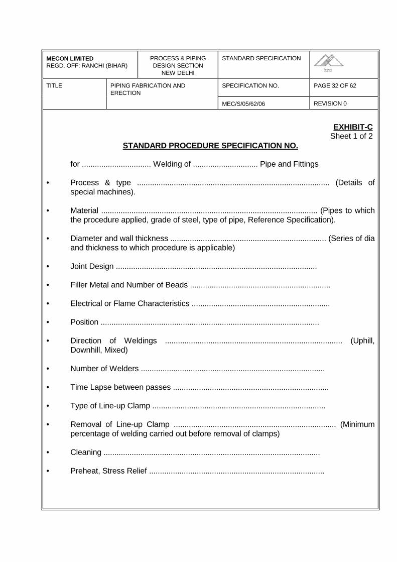
MECON LIMITEDREGD. OFF: RANCHI (BIHAR)
PROCESS & PIPINGDESIGN SECTION
NEW DELHI
STANDARD SPECIFICATION
TITLE PIPING FABRICATION ANDERECTION
SPECIFICATION NO. PAGE 32 OF 62
MEC/S/05/62/06 REVISION 0
EXHIBIT-CSheet 1 of 2
STANDARD PROCEDURE SPECIFICATION NO.
for ................................ Welding of .............................. Pipe and Fittings
• Process & type ......................................................................................... (Details ofspecial machines).
• Material .................................................................................................... (Pipes to whichthe procedure applied, grade of steel, type of pipe, Reference Specification).
• Diameter and wall thickness ........................................................................ (Series of diaand thickness to which procedure is applicable)
• Joint Design .............................................................................................
• Filler Metal and Number of Beads .................................................................
• Electrical or Flame Characteristics ................................................................
• Position .....................................................................................................
• Direction of Weldings .................................................................................. (Uphill,Downhill, Mixed)
• Number of Welders .....................................................................................
• Time Lapse between passes ........................................................................
• Type of Line-up Clamp ................................................................................
• Removal of Line-up Clamp ........................................................................... (Minimumpercentage of welding carried out before removal of clamps)
• Cleaning ....................................................................................................
• Preheat, Stress Relief .................................................................................
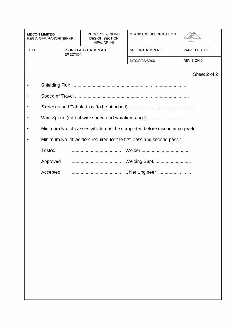
MECON LIMITEDREGD. OFF: RANCHI (BIHAR)
PROCESS & PIPINGDESIGN SECTION
NEW DELHI
STANDARD SPECIFICATION
TITLE PIPING FABRICATION ANDERECTION
SPECIFICATION NO. PAGE 33 OF 62
MEC/S/05/62/06 REVISION 0
Sheet 2 of 2
• Shielding Flux ............................................................................................
• Speed of Travel ..........................................................................................
• Sketches and Tabulations (to be attached) ....................................................
• Wire Speed (rate of wire speed and variation range) ........................................
• Minimum No. of passes which must be completed before discontinuing weld.
• Minimum No. of welders required for the first pass and second pass :
Tested : ....................................... Welder ......................................
Approved : ....................................... Welding Supt. ............................
Accepted : ....................................... Chief Engineer ...........................
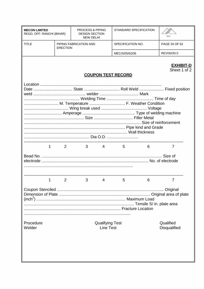
MECON LIMITEDREGD. OFF: RANCHI (BIHAR)
PROCESS & PIPINGDESIGN SECTION
NEW DELHI
STANDARD SPECIFICATION
TITLE PIPING FABRICATION ANDERECTION
SPECIFICATION NO. PAGE 34 OF 62
MEC/S/05/62/06 REVISION 0
EXHIBIT-DSheet 1 of 2
COUPON TEST RECORD
Location .............................................................................................................Date ................................... State ................................ Roll Weld ...................... Fixed positionweld ............................................... welder ................................... Mark.................................................. Welding Time .......................................... Time of day............................... M. Temperature ................................ F. Weather Condition ........................................ Wing break used ......................................... Voltage.................................. Amperage ............................................... Type of welding machine...................................................... Size ................................... Filler Metal......................................................................................................... Size of reinforcement........................................................................................... Pipe kind and Grade............................................................................................. Wall thickness........................................................... Dia O.D. ............................-------------------------------------------------------------------------------------------------------------------------
1 2 3 4 5 6 7
Bead No. ............................................................................................................ Size ofelectrode ................................................................................................ No. of electrode..................................................................................................
-------------------------------------------------------------------------------------------------------------------------1 2 3 4 5 6 7
Coupon Stenciled ................................................................................................ OriginalDimension of Plate .................................................................................. Original area of plate(inch2) ................................................................................ Maximum Load................................................................................................... Tensile S/ in. plate area....................................................................................... Fracture Location................................................................................................
Procedure Qualifying Test QualifiedWelder Line Test Disqualified

MECON LIMITEDREGD. OFF: RANCHI (BIHAR)
PROCESS & PIPINGDESIGN SECTION
NEW DELHI
STANDARD SPECIFICATION
TITLE PIPING FABRICATION ANDERECTION
SPECIFICATION NO. PAGE 35 OF 62
MEC/S/05/62/06 REVISION 0
Sheet 2 of 2
Max. tensile strength ................... min. tensile strength ..........................................
Avg. tensile strength ........................ Remarks on tensile strength ...........................
1. .................................................................................................................
2. .................................................................................................................
3. .................................................................................................................
4. .................................................................................................................
Remarks on Bend Tests
1. .................................................................................................................
2. .................................................................................................................
3. .................................................................................................................
4. .................................................................................................................
Remarks on Nick Tests
1. .................................................................................................................
2. .................................................................................................................
3. .................................................................................................................
4. .................................................................................................................
Other Tests ........................................................................................................
( Use back for additional remarks )
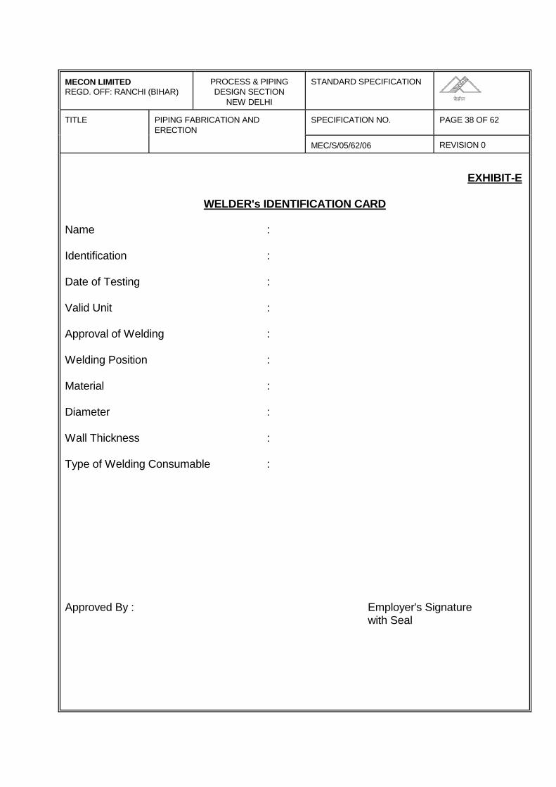
MECON LIMITEDREGD. OFF: RANCHI (BIHAR)
PROCESS & PIPINGDESIGN SECTION
NEW DELHI
STANDARD SPECIFICATION
TITLE PIPING FABRICATION ANDERECTION
SPECIFICATION NO. PAGE 38 OF 62
MEC/S/05/62/06 REVISION 0
EXHIBIT-E
WELDER's IDENTIFICATION CARD
Name :
Identification :
Date of Testing :
Valid Unit :
Approval of Welding :
Welding Position :
Material :
Diameter :
Wall Thickness :
Type of Welding Consumable :
Approved By : Employer's Signaturewith Seal
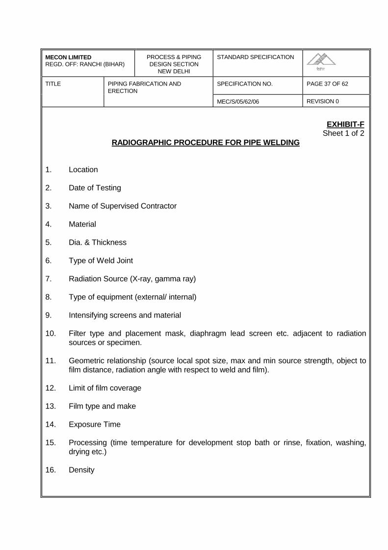
MECON LIMITEDREGD. OFF: RANCHI (BIHAR)
PROCESS & PIPINGDESIGN SECTION
NEW DELHI
STANDARD SPECIFICATION
TITLE PIPING FABRICATION ANDERECTION
SPECIFICATION NO. PAGE 37 OF 62
MEC/S/05/62/06 REVISION 0
EXHIBIT-FSheet 1 of 2
RADIOGRAPHIC PROCEDURE FOR PIPE WELDING
1. Location
2. Date of Testing
3. Name of Supervised Contractor
4. Material
5. Dia. & Thickness
6. Type of Weld Joint
7. Radiation Source (X-ray, gamma ray)
8. Type of equipment (external/ internal)
9. Intensifying screens and material
10. Filter type and placement mask, diaphragm lead screen etc. adjacent to radiationsources or specimen.
11. Geometric relationship (source local spot size, max and min source strength, object tofilm distance, radiation angle with respect to weld and film).
12. Limit of film coverage
13. Film type and make
14. Exposure Time
15. Processing (time temperature for development stop bath or rinse, fixation, washing,drying etc.)
16. Density
MECON LIMITEDREGD. OFF: RANCHI (BIHAR)
PROCESS & PIPINGDESIGN SECTION
NEW DELHI
STANDARD SPECIFICATION
TITLE PIPING FABRICATION ANDERECTION
SPECIFICATION NO. PAGE 38 OF 62
MEC/S/05/62/06 REVISION 0
Sheet 2 of 2
17. Sensitivity
18. Type of penetrameter
Approval of the COMPANY Signature of CONTRACTORwith seal

MECON LIMITEDREGD. OFF: RANCHI (BIHAR)
PROCESS & PIPINGDESIGN SECTION
NEW DELHI
STANDARD SPECIFICATION
TITLE PIPING FABRICATION ANDERECTION
SPECIFICATION NO. PAGE 39 OF 62
MEC/S/05/62/6 REVISION 0
WELDING SPECIFICATION CHART EXHIBIT-GSheet 1 of 2
Class :
Material Specification :
Pipes : API 5L Gr. X 60, API 5L Gr. B APIS Gr. X 42
Fittings : A 105, A234 Gr. WPB. MSS-SP-75, Gr. WPHY42, MSS-S
Flanges : Alos, MSS-SP-44 Gr. F42, MSS-SP as Gr. WPH 60
Other : 44 Gr. F6C
Base Metal of NCL :
Welding Processes : Groove Joints : Butt
Root Pass SMAW Filler Pass SMAW Root Pass SMAW Filler Pass SMAW Filler Joints/Socket Joints : SMAW
Welding Materials : Groove Joints : Butt
Root Pass E6010G/ E7010G Filler Pass F7010G/ E8010G/ E8818GRoot Pass E7010/ E7018G/ E8018G Filler Pass F7016/ E7018G/ E80118G
Filler Joints/ Socket Joints : E7016/ E7018/ E7018G/ E8018G
Backing Page Consumable :
Gases : Purging Sheilding
Gas Composition : Purging Sheilding
Preheating : 10 min for all welds, 100°C Post heating
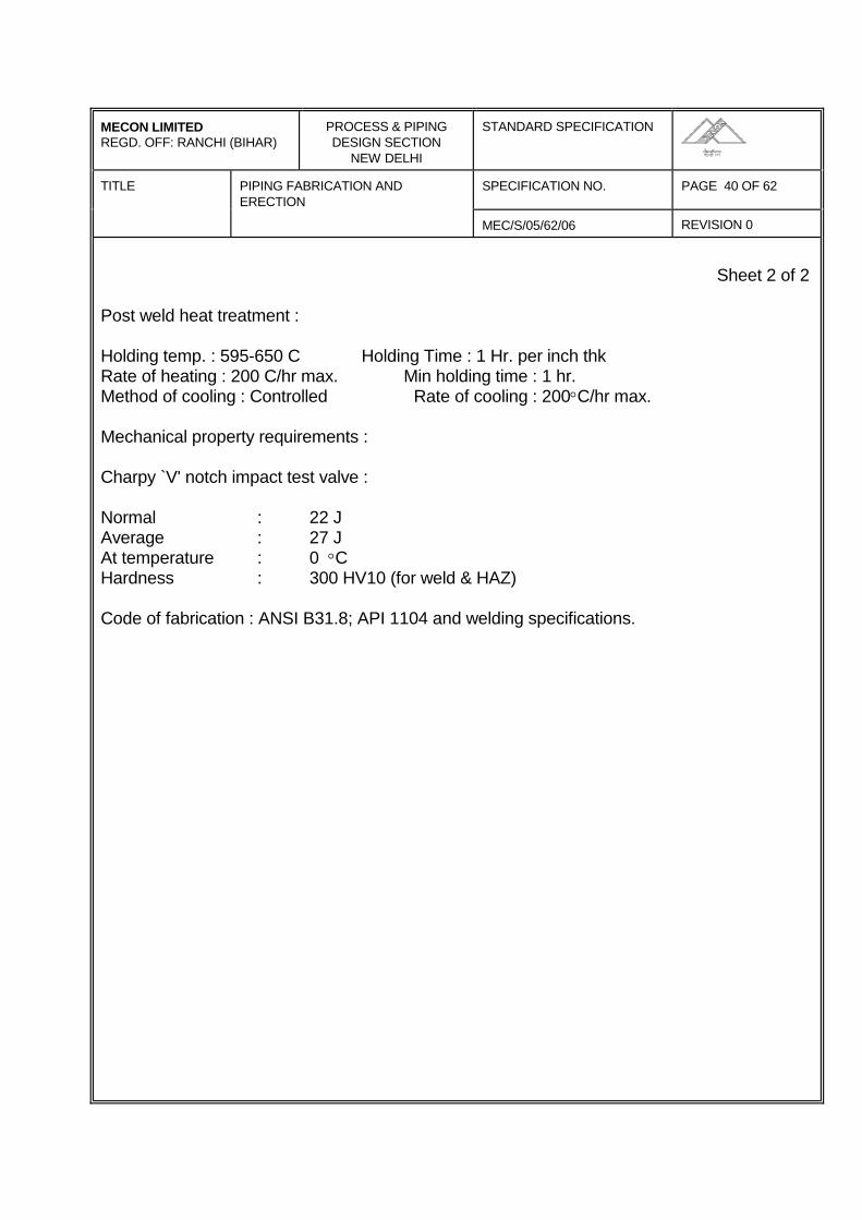
MECON LIMITEDREGD. OFF: RANCHI (BIHAR)
PROCESS & PIPINGDESIGN SECTION
NEW DELHI
STANDARD SPECIFICATION
TITLE PIPING FABRICATION ANDERECTION
SPECIFICATION NO. PAGE 40 OF 62
MEC/S/05/62/06 REVISION 0
Sheet 2 of 2
Post weld heat treatment :
Holding temp. : 595-650 C Holding Time : 1 Hr. per inch thkRate of heating : 200 C/hr max. Min holding time : 1 hr.Method of cooling : Controlled Rate of cooling : 200°C/hr max.
Mechanical property requirements :
Charpy `V' notch impact test valve :
Normal : 22 JAverage : 27 JAt temperature : 0 °CHardness : 300 HV10 (for weld & HAZ)
Code of fabrication : ANSI B31.8; API 1104 and welding specifications.
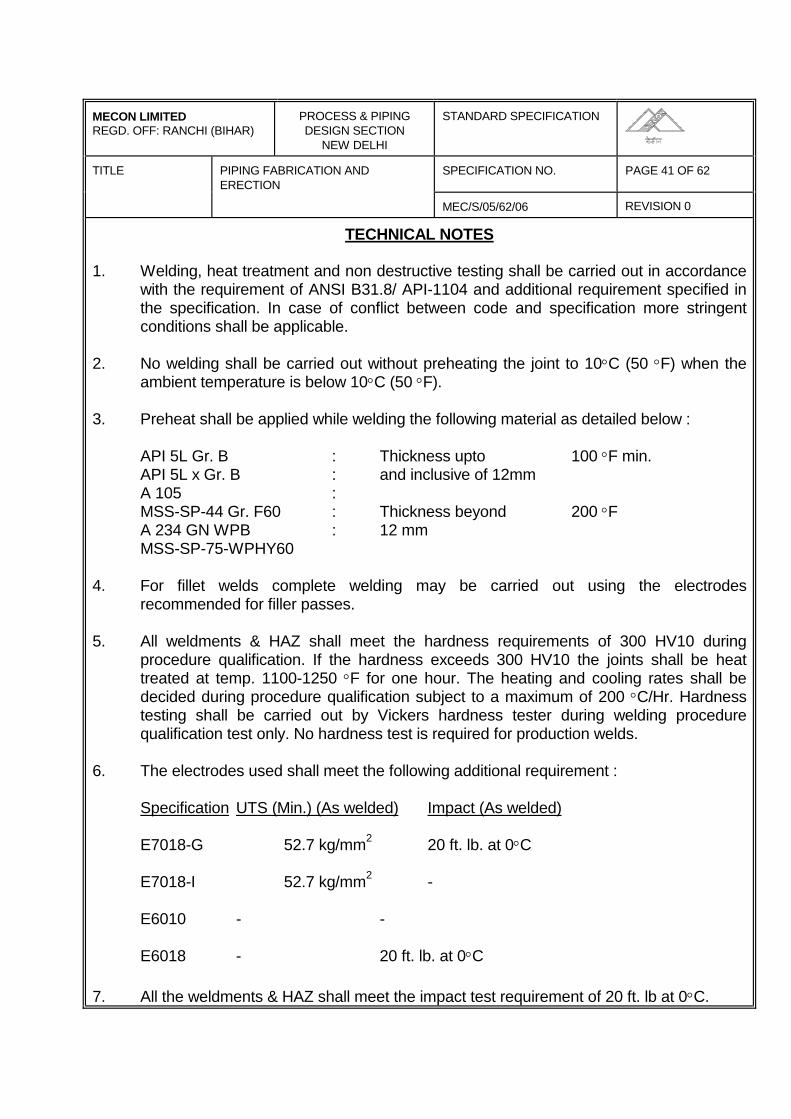
MECON LIMITEDREGD. OFF: RANCHI (BIHAR)
PROCESS & PIPINGDESIGN SECTION
NEW DELHI
STANDARD SPECIFICATION
TITLE PIPING FABRICATION ANDERECTION
SPECIFICATION NO. PAGE 41 OF 62
MEC/S/05/62/06 REVISION 0
TECHNICAL NOTES
1. Welding, heat treatment and non destructive testing shall be carried out in accordancewith the requirement of ANSI B31.8/ API-1104 and additional requirement specified inthe specification. In case of conflict between code and specification more stringentconditions shall be applicable.
2. No welding shall be carried out without preheating the joint to 10°C (50 °F) when theambient temperature is below 10°C (50 °F).
3. Preheat shall be applied while welding the following material as detailed below :
API 5L Gr. B : Thickness upto 100 °F min.API 5L x Gr. B : and inclusive of 12mmA 105 :MSS-SP-44 Gr. F60 : Thickness beyond 200 °FA 234 GN WPB : 12 mmMSS-SP-75-WPHY60
4. For fillet welds complete welding may be carried out using the electrodesrecommended for filler passes.
5. All weldments & HAZ shall meet the hardness requirements of 300 HV10 duringprocedure qualification. If the hardness exceeds 300 HV10 the joints shall be heattreated at temp. 1100-1250 °F for one hour. The heating and cooling rates shall bedecided during procedure qualification subject to a maximum of 200 °C/Hr. Hardnesstesting shall be carried out by Vickers hardness tester during welding procedurequalification test only. No hardness test is required for production welds.
6. The electrodes used shall meet the following additional requirement :
Specification UTS (Min.) (As welded) Impact (As welded)
E7018-G 52.7 kg/mm2 20 ft. lb. at 0°C
E7018-I 52.7 kg/mm2 -
E6010 - -
E6018 - 20 ft. lb. at 0°C
7. All the weldments & HAZ shall meet the impact test requirement of 20 ft. lb at 0°C.
MECON LIMITEDREGD. OFF: RANCHI (BIHAR)
PROCESS & PIPINGDESIGN SECTION
NEW DELHI
STANDARD SPECIFICATION
TITLE PIPING FABRICATION ANDERECTION
SPECIFICATION NO. PAGE 42 OF 62
MEC/S/05/62/06 REVISION 0
ANNEXURE-2
1.0 DESTRUCTIVE TESTING OF WELDED JOINT - BUTT WELDS
1.1 Preparation
Having passed the visual and the non destructive inspection, the test weld shall besubjected to mechanical test.
After satisfactory completion of all visual and non destructive testing the procedure testweld shall be set aside for a period not less than 24 hours. No further work on the testweld and no cutting of test specimens from the weld be performed till a period of atleast 24 hours has expired.
Weld specimens, for pipe diameter greater than or equal to 12.3/4" shall be taken fromthe positions indicated in Fig. 1 of this specification from areas as free from defects aspossible. For this reason it is necessary to take the previous non destructive tests intoaccount. The minimum no. of tests to be carried out is given in Table-I of thisspecification.
The test shall be carried out at laboratories approved by COMPANY. The specimensshall be prepared in accordance with the figure given in the paragraphs which refer tothe individual test.
MECON LIMITEDREGD. OFF: RANCHI (BIHAR)
PROCESS & PIPINGDESIGN SECTION
NEW DELHI
STANDARD SPECIFICATION
TITLE PIPING FABRICATION ANDERECTION
SPECIFICATION NO. PAGE 43 OF 62
MEC/S/05/62/06 REVISION 0
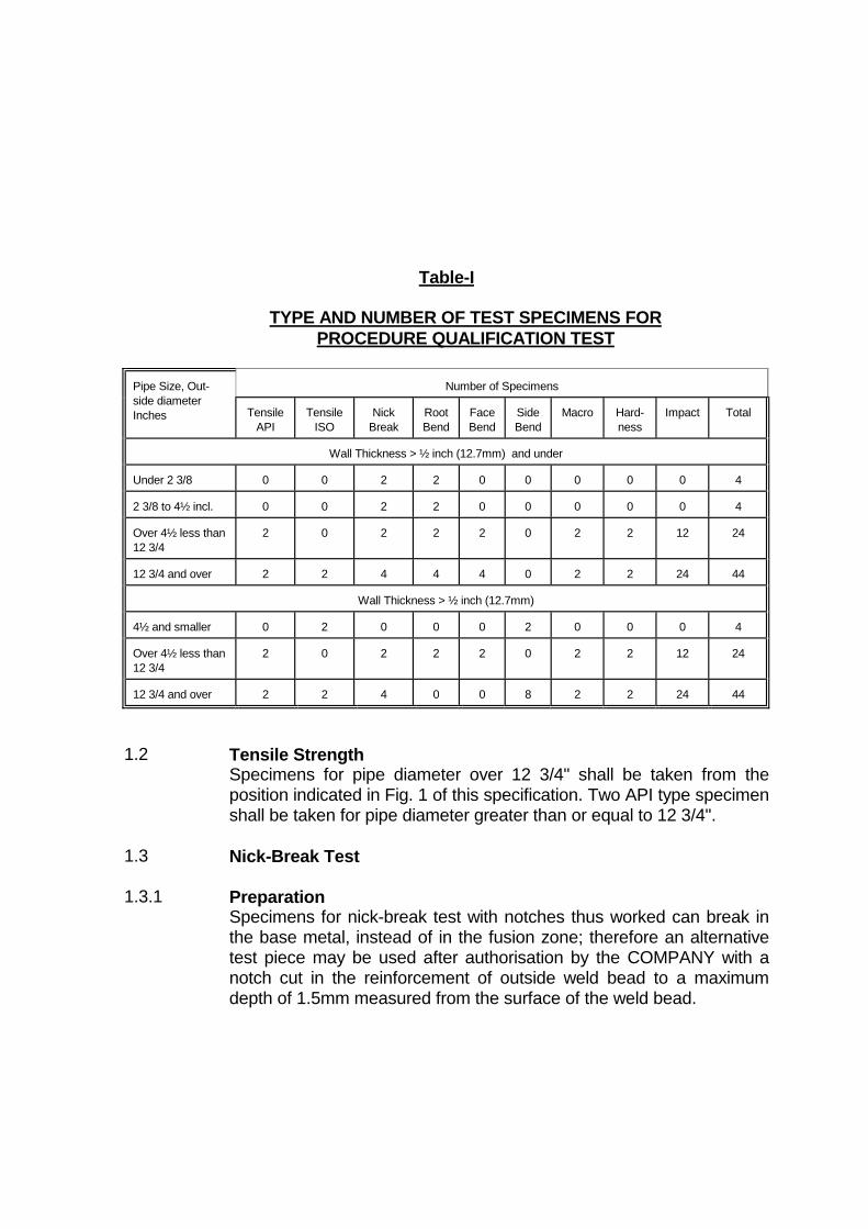
Table-I
TYPE AND NUMBER OF TEST SPECIMENS FORPROCEDURE QUALIFICATION TEST
Number of SpecimensPipe Size, Out-side diameterInches Tensile
APITensile
ISONick
BreakRootBend
FaceBend
SideBend
Macro Hard-ness
Impact Total
Wall Thickness > ½ inch (12.7mm) and under
Under 2 3/8 0 0 2 2 0 0 0 0 0 4
2 3/8 to 4½ incl. 0 0 2 2 0 0 0 0 0 4
Over 4½ less than12 3/4
2 0 2 2 2 0 2 2 12 24
12 3/4 and over 2 2 4 4 4 0 2 2 24 44
Wall Thickness > ½ inch (12.7mm)
4½ and smaller 0 2 0 0 0 2 0 0 0 4
Over 4½ less than12 3/4
2 0 2 2 2 0 2 2 12 24
12 3/4 and over 2 2 4 0 0 8 2 2 24 44
1.2 Tensile StrengthSpecimens for pipe diameter over 12 3/4" shall be taken from theposition indicated in Fig. 1 of this specification. Two API type specimenshall be taken for pipe diameter greater than or equal to 12 3/4".
1.3 Nick-Break Test
1.3.1 PreparationSpecimens for nick-break test with notches thus worked can break inthe base metal, instead of in the fusion zone; therefore an alternativetest piece may be used after authorisation by the COMPANY with anotch cut in the reinforcement of outside weld bead to a maximumdepth of 1.5mm measured from the surface of the weld bead.
MECON LIMITEDREGD. OFF: RANCHI (BIHAR)
PROCESS & PIPINGDESIGN SECTION
NEW DELHI
STANDARD SPECIFICATION
TITLE PIPING FABRICATION ANDERECTION
SPECIFICATION NO. PAGE 45 OF 62
MEC/S/05/62/06 REVISION 0
1.4 Macroscopic Inspection
1.4.1 Preparation
Specimens shall be taken from the positions indicated in Fig. 1 of thisspecification and shall be prepared in accordance with ASTM E2 and E3.
The width of the macrosection has to be at least three times the width of theweld. The section is to be prepared by grinding or polishing and etching toclearly reveal the weld metal and heat effected zone.
1.4.2 Method
Specimens shall be carefully examined under the microscope with amagnification of at least 25 times. The COMPANY may ask for a macrographwith 5 times magnification for documentation purposes.
1.4.3 Requirements
Under macroscopic examination, the welded joints shall show good penetrationand fusion, without any defect exceeding the limits stated in the evaluationcriteria of the nick break test.
1.5 Hardness Test
1.5.1 Preparation
The prepared macrosection is to be used for hardness testing using the Vickersmethod with 100 N (10 kg) load. Indentations are to be made along traverseseach approximately 1mm below the surface at both side of the weld.
In the weld metal a minimum of 6 indentations equally spaced along thetraverses are to be made. The HAZ indentations are to be made along thetraverses for approximately 0.5mm each into unaffected material, and starting asclose to the fusion line as possible.
One indentation at each side of the weld along each traverse has to be made onparent metal. Reference is made to fig. 3 of this specification. The indentationare to be made in the adjacent region as well as on the opposite side of themacrosection along the specified traverses.
MECON LIMITEDREGD. OFF: RANCHI (BIHAR)
PROCESS & PIPINGDESIGN SECTION
NEW DELHI
STANDARD SPECIFICATION
TITLE PIPING FABRICATION ANDERECTION
SPECIFICATION NO. PAGE 46 OF 62
MEC/S/05/62/06 REVISION 0
1.5.2 Method
The test shall be carried out in accordance with Recommendation ISO R81,Vickers hardness, using laboratory type machine controlled as per-recommendation of ISO R 146 and using a diamond pyramid penetrator set at2.37 rad. (136) with a load of 100 N (10 kg).
1.5.3 Requirements
Hardness value shall not exceed 300 H VI0 . In case of a single reading slightly(+10 HV) higher than the specified limit, further indentations should be made tocheck if the high value was an isolated case.
All the hardness values obtained from the heat effected zone shall not exceed100 HV with respect to the average hardness of the values obtained for thebase metal.
If these additional tests mentioned above give a hardness within thespecification limit, the slightly higher value may be accepted.
1.6 Charpy-V-notch Impact Test
1.6.1 Specimens shall be taken from the position indicated in Fig. 1 of thisspecification. The test specimens will be prepared in accordance with ISO R148. Charpy V-notch specimens shall have dimensions as given in Fig. 3 of thespecification.
Three test specimens shall be taken from each sample and they shall be cutand worked so that their length is transversal and perpendicular to the weldbead with the notch position as shown in Fig. 4 of this specification. The notchshall be perpendicular to the roller surface. The test specimens width shalldepend upon the pipe wall nominal thickness as following :
MECON LIMITEDREGD. OFF: RANCHI (BIHAR)
PROCESS & PIPINGDESIGN SECTION
NEW DELHI
STANDARD SPECIFICATION
TITLE PIPING FABRICATION ANDERECTION
SPECIFICATION NO. PAGE 47 OF 62
MEC/S/05/62/06 REVISION 0
-------------------------------------------------------------------------------------------------------Nominal wall thickness in Test Specimens width in
mm mm-------------------------------------------------------------------------------------------------------> 12 12-------------------------------------------------------------------------------------------------------> 9.5 and ≤ 12 7.5-------------------------------------------------------------------------------------------------------≥ 7 and ≤ 9.5 5-------------------------------------------------------------------------------------------------------< 7 2.5-------------------------------------------------------------------------------------------------------
1.6.2 Test Method
The test shall be carried out as indicated in ISO R 148 "Beam Impact Test V-notch.
Test pieces shall be immersed in a thermostatic bath and maintained at the testtemperature for at least 15 minutes. They shall than be placed in the testingmachine and broken within 5 seconds of their removal from the batch.
1.6.3 Requirements
The impact energy shall be greater or equal to :-
-------------------------------------------------------------------------------------------------------Test Specimens in Average of Minimum
mm Three specimens Single ValueJoule (min) (Note-2) Joules (Note 1)
-------------------------------------------------------------------------------------------------------10 27 227.5 21.5 17.55 18.5 15.02.5 10.0 8.0
-------------------------------------------------------------------------------------------------------Note:1) Only one value is permitted to be lower than average upto the value
specified.
MECON LIMITEDREGD. OFF: RANCHI (BIHAR)
PROCESS & PIPINGDESIGN SECTION
NEW DELHI
STANDARD SPECIFICATION
TITLE PIPING FABRICATION ANDERECTION
SPECIFICATION NO. PAGE 48 OF 62
MEC/S/05/62/06 REVISION 0
1.7 Bend Test Requirements
The bend test specimens shall be made and tested as per the requirements ofAPI-1104 sixteenth edition - May, 1983 except that the dimensions of Jig forguided bend test fig. 5 para 2.6 API-1104 shall be modified as follows :
Radius of the plunger °A' = 2 tRadius of the die °B' = 3 t + 1.6mmWidth of the die °C' = 50.8
The acceptance criteria shall however be as per para 2.643 and 2.653 of API-1104 sixteenth edition - May, 1983.
Note t = Thickness of Specimen (nominal)
MECON LIMITEDREGD. OFF: RANCHI (BIHAR)
PROCESS & PIPINGDESIGN SECTION
NEW DELHI
STANDARD SPECIFICATION
TITLE PIPING FABRICATION ANDERECTION
SPECIFICATION NO. PAGE 49 OF 62
MEC/S/05/62/06 REVISION 0
ANNEXURE-31.0 ULTRASONIC INSPECTION
In addition to the radiographic inspection ultrasonic inspection is required as perconditions mentioned in Annexure-1 of this specification.
This section concerns manual ultrasonic inspection. However ultrasonicinspection by automatic equipment may be used if approved by the COMPANY.
1.1 Equipment and Operators
The CONTRACTOR who carries out the ultrasonic inspection shall havesufficient qualified personnel, equipment and instrument at his disposal to beable to effect the tests without hindering or delaying the pipeline assemblyoperations.
• Calibrate the equipment;• Perform an operational test under production conditions;• Interpret the screen picture;• Evaluate the size and location of reflectors• Interpret the type of defects detected.
The COMPANY has the option of checking the ability of personnel employed forultrasonic testing by means of qualification tests.
The CONTRACTOR appointed to carry out UT inspection shall supply theinstruments necessary for their execution on site.
1.2 Specification for Ultrasonic Testing Procedure
Qualification
Before work begins the CONTRACTOR shall present a specification describingthe proposed U.T. procedure qualification.
This specification shall be state, as an indication only but not limited to thefollowing information :
• Type of U.T. equipment used
MECON LIMITEDREGD. OFF: RANCHI (BIHAR)
PROCESS & PIPINGDESIGN SECTION
NEW DELHI
STANDARD SPECIFICATION
TITLE PIPING FABRICATION ANDERECTION
SPECIFICATION NO. PAGE 50 OF 62
MEC/S/05/62/06 REVISION 0
• Type and dimensions of transducers• Frequency range• Details for calibration• Coupling medium• Inspection technique• Record details• Reference to the welding procedure where it is intended to adopt the
specification.• Temperature range of the joints to be inspected.
1.3 Qualification of Ultrasonic Inspection Procedure
The ultrasonic inspection procedure shall be approved by the COMPANY.Before inspection begins, the COMPANY may require the qualification test ofthe ultrasonic inspection procedure. This specification test consists in testing(under normal operating conditions) some CONTRACTOR welds madeaccording to the same production procedure, when there are typical defects thetest intends to detect.
1.4 Test Procedure
Circumferential weld shall be inspected from both sides using angled. Probes.
The surface with which the probe comes into contact shall be free of metalspatter, dirt, iron oxide and scales of any type: therefore it shall be necessary toclean a strip at least 50mm wide on both sides of the weld with steel - wirebrushes and anyhow the cleaned strip must be atleast wide enough to allow fullskip examination.
If during the test, echoes of doubtful origin appear, it shall be necessary toinspect a convenient area on the pipe surface, close to the weld, with a straightbeam transducer in order to check whether any manufacturing defects arepresent which could have interfered with the ultrasonic beam.
By way of an example, the equipment shall include but not be limited to thefollowing :
• Ultrasonic equipment and coupling medium• Sample sections for calibration of instruments.
MECON LIMITEDREGD. OFF: RANCHI (BIHAR)
PROCESS & PIPINGDESIGN SECTION
NEW DELHI
STANDARD SPECIFICATION
TITLE PIPING FABRICATION ANDERECTION
SPECIFICATION NO. PAGE 51 OF 62
MEC/S/05/62/06 REVISION 0
• Equipment for cleaning of surface to be examined.• Rulers calibrated in centimeters for exact location of the position of
defects.
The characteristics of the above-listed instruments and equipment shallguarantee:
a) that the required standards of the inspection procedure, as previouslyestablished and approved by the COMPANY, are satisfied.
b) continuous operation
All the instruments and equipment shall be approved by the COMPANYbefore being used. The COMPANY has the authority to reject any itemwhich is considered unsuitable. The decision of the COMPANY is final. The CONTRACTOR appointed to carry out ultrasonic inspection shallalso ensure the operational efficiency and maintenance of theinstruments and equipment, and shall immediately substitute any itemrejected by the COMPANY.
All the instrument and equipment necessary for carrying out ultrasonicinspection on site shall satisfy the requirements laid down by the publicboard of institutions which regulate "safety at work".
1.5 Ultrasonic Instruments
The ultrasonic instruments :
• Shall be each pulse type, able to generate, receive and display, on thescreen a cathode ray tube (CRT) pulse, at frequencies between 1 and 6mhz. The useful part of the CRT screen shall be at least 70m wide and atleast 50mm high.
• Shall have various amplification, with steps of 1 or 2 dB over a range of aleast 60 dB.
• The regulation control shall be accurate to within 1 dB and this accuracyshall be certified by the instrument manufacturer.
MECON LIMITEDREGD. OFF: RANCHI (BIHAR)
PROCESS & PIPINGDESIGN SECTION
NEW DELHI
STANDARD SPECIFICATION
TITLE PIPING FABRICATION ANDERECTION
SPECIFICATION NO. PAGE 52 OF 62
MEC/S/05/62/06 REVISION 0
• May be powered by a battery or an electric generator. In the first case,the autonomy of operation (endurance) of the instrument shall besufficient to carry on working without frequent interruptions, and theinstrument shall be equipped with an automatic switch which switches itoff when the battery runs down, in the second case, there must be avoltage stabilising device with a tolerance of 2 volts.
1.6 Probes
The probes used shall have dimensions, frequencies, and a refraction anglesuited to the type of steel, the diameter the thickness of the pipeline and to thejoint design.
1.7 Reference Sample Pieces
The efficiency of the equipment used, the effective refraction angle of the probe,and the beam output points, shall be checked using a V1 and V2 sample block,IIW type or the calibration block ASTM E-428.
For the calibration of runs and the regulation of detection sensitivity during thetest, a calibration piece be used. This piece shall be taken from the productionmaterial, and will be at least 150mm long (measured in the direction of the axis),and at least 50mm wide (measured in the direction of the circumference), (seeFig. 4 of this specification).
In the middle of the inside and the outside surface of the calibration piece agroove shall be made. The groove will have a rectangular cross-section, a flatbottom and the following dimensions :-
• Depth : 1 +/- 0.1mm
• Breadth (measured parallel to the 150mm side) : 1 +/- 0.1mm
• Length (measured parallel to the 50mm side) not less than 30mm.
In addition, the calibration piece shall have a hole, 2mm in diameter, passingthrough its thickness and positioned so that during calibration the echoesreturning from the two grooves do not interfere with those returning from thehole.
MECON LIMITEDREGD. OFF: RANCHI (BIHAR)
PROCESS & PIPINGDESIGN SECTION
NEW DELHI
STANDARD SPECIFICATION
TITLE PIPING FABRICATION ANDERECTION
SPECIFICATION NO. PAGE 53 OF 62
MEC/S/05/62/06 REVISION 0
1.6 Calibration
For a precise check of the sound paths necessary for a full inspection of theweld joint, the probe shall be moved (half skip and full skip distance) untilinternal and external notches on the test piece are detected (see Fig. 5 of thisspecification).
The relevant defect limits the path lengths on the time base. The calibration ofreference sensitivity is obtained by utilising the through drilled test hole in thethickness of the reference block to draw the distance amplitude correction curverelevant to the test probe.
Calibration shall be carried out according to the following procedure : place itsinternal vertex until the maximum height of echo is displayed on the screen; thisecho is adjusted to 80% of full screen height by means of the sensitivity adjusterset in dB. Without varying the amplification, the probe placed at full skip distancefrom the hole is moved to detect the external vertex the hole until the maximumheight of echo is obtained. The straight line connecting the peaks of the twoechoes obtained by the above procedure, represents the 100% reference level,while the one connecting the two points at half height of the same echoesrepresents "50% reference level".
The two straight lines shall be marked on the screen with a pen. Calibrationshallbe repeated each time tests are re-started at intervals not longer than 30minutes during normal operations; each time the conditions fixed in advance arealtered. This calibration is applicable provided that the crystal of the probe is 8 x9mm size. Should this size of the crystal be different, the value of the sensitivityobtained from the calibration by a crystal of a different size shall be brought tothe value of sensitivity obtained from the calibration by a 8 x 9mm crystal. Thesensitivities of the two different size probes shall be compared through theechoes obtained on the notch of the test piece with the probe position at halfskip of the distance.
1.9 Regulation of Amplification during Production Testing
The amplification during production testing shall be obtained by adding 2-6 dB(according to the surface condition of the pipe and its cleanness) to thereference amplification.
MECON LIMITEDREGD. OFF: RANCHI (BIHAR)
PROCESS & PIPINGDESIGN SECTION
NEW DELHI
STANDARD SPECIFICATION
TITLE PIPING FABRICATION ANDERECTION
SPECIFICATION NO. PAGE 54 OF 62
MEC/S/05/62/06 REVISION 0
1.10 Qualification of Ultrasonic Testing Operators
Before the inspection begins or during the same inspection, the COMPANY mayrequire a qualification test for the ultrasonic equipment operators.
1.11 Evaluation of Indications given by Ultrasonic Tests
Each time that echoes from the weld bead appear during production testing, theinstrument amplification shall be altered to coincide with the referenceamplifications and the probe shall be moved until maximum respond is obtainedpaying attention all the time to the probetube coupling.
If, under these conditions, the height of the defer echo is equal to or greater thanthat of the reference echo, the defect shall be evaluated. If the defect has alsobeen detected by the radiographic and or visual examination, the dimensionsshall be judged according to the type of examination which detects the greaterdefects. Returns which are less than 50% of the reference echo, will not beconsidered. It returns are above 50% but lower than 100% of the referenceecho, and if the operator has good reasons to suspect that the returns arecaused by unfavorably oriented cracks, he shall inform the COMPANY.Moreover, when there is a defect to be repaired such defect shall be removedfor a length corresponding to the one where no more return echo is given.
1.12 Other Equipment
The use of rules calibrated in centimeters, attached if possible to the probe, forthe precise location of the position of welding defects, it recommended. Defectlocation is effected by measuring the projection distance between the probeoutput and the reflecting surface.
The operators carrying out the tests shall have besides the probing instrument,tools for cleaning the pipe surface (files, brushes, etc.) as well as the couplingliquid or paste appropriate for the temperature of the section to be examined.
MECON LIMITEDREGD. OFF: RANCHI (BIHAR)
PROCESS & PIPINGDESIGN SECTION
NEW DELHI
STANDARD SPECIFICATION
TITLE PIPING FABRICATION ANDERECTION
SPECIFICATION NO. PAGE 55 OF 62
MEC/S/05/62/06 REVISION 0
ANNEXURE-4
RADIOGRAPHY
1.0 SCOPE
This annexure covers the radiographic inspection of all types of welded joints ofthe main pipeline. The welded joints shall include the following :
i) Full girth welds on the mainline construction including double jointing ofpipe, if adopted.
ii) Welds for installation of block valves, insulating joints and otherappurtenances and tie-ins.
iii) Welds at scraper launching and receiving barrels
iv) Terminal Piping.
2.0 APPLICABLE STANDARDS
This specification shall apply in conjunction with the following (all latest edition) :
i) API 1104, Standard for welding pipelines and related facilities.
ii) ANSI B31.8, code for Gas Transmission and Distribution Piping Systems.
iii) ANSI B31.4, Code for Liquid Petroleum Transportation Piping System.
iv) ASTM E94, Recommended practice for Radiographic Testing.
v) ASTM, E 142, Standard Method for Controlling Quality of RadiographicTesting.
vi) The American Society for non-destructive Testing. RecommendedPractice No. SNT-TC-1A Supplement-A.
MECON LIMITEDREGD. OFF: RANCHI (BIHAR)
PROCESS & PIPINGDESIGN SECTION
NEW DELHI
STANDARD SPECIFICATION
TITLE PIPING FABRICATION ANDERECTION
SPECIFICATION NO. PAGE 56 OF 62
MEC/S/05/62/06 REVISION 0
3.0 PROCEDURE
3.1 The radiographic examination procedure to be adopted shall be submitted bythe CONTRACTOR as per Exhibit-F.
3.2 The procedure of radiographic examination shall be qualified to the entiresatisfaction of COMPANY prior to use. It shall include but not be limited to thefollowing requirements.
i) Lead foil intensifying screens, at the rear of the film shall be used in allexposures.
ii) Type 2 and 3 films as per ASTM E-94 shall be used.iii) A densitometer shall be used to determine film density. The transmitted
film density shall be 2.0 and 3.5 through out the weld. The unexposedbase density of the film shall not exceed 0.30.
iv) Radiographic identification system and documentation for radiographicinterpretation reports and their recording system.
3.3 The CONTRACTOR shall qualify each procedure in the presence of theCOMPANY prior to use.
3.4 The procedure of radiographic examination shall produce radiographs ofsufficient density, clarity and contrast so that defects in the weld or in the pipeadjacent to the weld, and the outline and holes of the pentrameter are clearlydiscernible.
3.5 All the girth welds of mainline shall be subjected to 100% radiographicexamination. The CONTRACTOR shall furnish all the radiographs to theCOMPANY, immediately after processing them, together with the correspondinginterpretation reports on approved format. The details of the radiographsalongwith the joint identification number shall be duly entered in a register andsigned by the CONTRACTOR and submitted to the COMPANY for approval.
3.6 When the radiation source and the film are both on the outside of the weld andlocated diametrically opposite each other, the maximum acceptable length offilm for each exposure shall not exceed the values given in Table 4 of API 1104.The minimum film overlap, in such cases, shall be 40mm. The ellipse exposuretechnique may be used on nominal pipe sizes of 2 inch and smaller providedthat the source to film distance used is a minimum of 12 inches.
MECON LIMITEDREGD. OFF: RANCHI (BIHAR)
PROCESS & PIPINGDESIGN SECTION
NEW DELHI
STANDARD SPECIFICATION
TITLE PIPING FABRICATION ANDERECTION
SPECIFICATION NO. PAGE 57 OF 62
MEC/S/05/62/06 REVISION 0
3.7 Three copies of each acceptable radiographic procedure (as outlined inSpecification no. MEC/S/O5/62/02) and three copies of radiographic qualificationrecords, shall be supplied to COMPANY. One set of the qualifying radiographson the job shall be kept by the CONTRACTOR's authorised representative to beused as a standard for the quality of production radiographs during the job. Theother two sets shall be retained by COMPANY for its permanent record.
3.8 Three copies of the exposure charts relating to material thickness, kilo voltage,source to film distance and exposure time shall also be made available toCOMPANY by the CONTRACTOR.
3.9 The CONTRACTOR shall, on a daily basis, record for each radiograph (1)radiography number (2) approximate chainage of weld location, (3) whether ornot the welds meet the specified acceptance standards and (4) the nature andapproximate location of unacceptable defects observed. It must be possible torelate to a particular butt weld and welder on piping drawing and pipelinealignment drawing.
3.10 Each day's production of processed radiographs shall be properly packagedseparately, identified by at least the (1) date, (2) radiographic unit, (3) joblocations, (4) starting and ending progress survey stations and (5) shall includeoriginal and three copies of the daily radiographic record. The package shall besubmitted to the COMPANY daily when possible, but in no event later than noonof the following day.
3.11 The CONTRACTOR shall provide all the necessary facilities at site, such as adark room with controlled temperature, film viewer etc. to enable the COMPANYto examine the radiographs.
3.12 The CONTRACTOR, if found necessary, may modify the procedure ofradiographic examination suiting the local conditions prevailing. This shall,however, be subject to the approval of the COMPANY.
3.13 COMPANY shall have free access to all the CONTRACTOR's work facilities inthe field.
3.14 Any approval granted by the COMPANY shall not relieve the CONTRACTOR ofhis responsibilities and guarantees.
MECON LIMITEDREGD. OFF: RANCHI (BIHAR)
PROCESS & PIPINGDESIGN SECTION
NEW DELHI
STANDARD SPECIFICATION
TITLE PIPING FABRICATION ANDERECTION
SPECIFICATION NO. PAGE 58 OF 62
MEC/S/05/62/06 REVISION 0
4.0 RADIATION SOURCE
4.1 Radiographic examination shall be carried out using x-radiations. Radiographicexamination by Gamma rays may be allowed, at the discretion of theCOMPANY, in case of inaccessible joints.
4.2 Whenever possible, pipeline welds will be inspected by placing the radiationsource inside the pipe, on the pipeline axis, with a radiation of 6.28 rad. (360°).
If it is impossible to place the radiation source inside the pipe, the weld will beinspected with the source on the outside. An overlap of at least 40mm at theends of each film shall be required to ensure that the first and last locationincrement numbers are common to successive films and to establish that nopart of a weld has been omitted.
5.0 LEVEL OF QUALITY
The quality level of radiographic sensitivity required for radiographic inspectionshall be at least equivalent to the values in Figure-6.
6.0 PENETRAMETERS
6.1 The image quality indicator (abbreviation : IQI) shall be used for the qualificationof the welding procedure and during normal line production. Radiographicsensitivity shall be measured with the wire image quality indicator(Penetrameter). The penetrameter shall be selected according to DIN 54109 orISO 1027. For radiographs made with the source on the outside, a penetrametershall be placed on each side of the film with the smaller wire of the penetrameterturned towards the end of the film itself. When a complete weld is radiographedin a single exposure using a source inside the piping, four penetrametersapproximately equally spaced around the circumference shall be used. Duringthe procedure qualification, IQI shall be placed both on the source side and onthe film side. The sensitivity obtained with IQI on the source side shall not beless than the values shown in Fig. 6 of this specification.
The sensitivity limit may be considered to have been reached when the outlineof the IQI, its identification number and the wire of the required diameter showup clearly on the radiographs.
MECON LIMITEDREGD. OFF: RANCHI (BIHAR)
PROCESS & PIPINGDESIGN SECTION
NEW DELHI
STANDARD SPECIFICATION
TITLE PIPING FABRICATION ANDERECTION
SPECIFICATION NO. PAGE 59 OF 62
MEC/S/05/62/06 REVISION 0
The COMPANY may authorise use of types of IQI other than those planned,provided that they conform with recognised standards and only if theCONTRACTOR is able to demonstrate that the minimum sensitivity levelrequired is obtained. For this demonstration, a test shall be carried outcomparing the IQI specified and the CONTRACTOR's to show up theidentification number and other details of the proposed IQI, which must bevisible in the test radiograph.
7.0 FILM IDENTIFICATION MARKERS
All films shall be clearly identified by lead numbers, letters, and/ or markers. Theimage of the markers shall appear on the films, without interfering with theinterpretation. These markers positions shall also be marked on the part to beradiographed and shall be maintained during radiography.
8.0 PROTECTION AND CARE OF FILM
8.1 All unexposed films shall protected and stored properly as per the requirementsof API 1104 standard and ASTM E 94.
8.2 The exposed and unexposed film shall be protected from heat, light, dust andmoisture. Sufficient shielding shall be supplied to prevent exposure of film todamaging radiation prior to and following the use of the film for radiographicexposure.
9.0 RE-RADIOGRAPHY
9.1 The weld joints shall be re-radiographed in case of unsatisfactory quality of theradiographs, at the expense of the CONTRACTOR.
9.2 All the repaired weld joints shall be re-radiographed at no extra cost to theCOMPANY in the same manner as that followed for the original welds. Inaddition, the repaired weld area shall be identified with the original identificationnumber plus the letter `R' to indicate the repair.
9.3 When evaluating repair film, radiographers shall compare each section(exposure) of the weld with the original film to assure repair was correctlymarked and original defect removed.
MECON LIMITEDREGD. OFF: RANCHI (BIHAR)
PROCESS & PIPINGDESIGN SECTION
NEW DELHI
STANDARD SPECIFICATION
TITLE PIPING FABRICATION ANDERECTION
SPECIFICATION NO. PAGE 60 OF 62
MEC/S/05/62/06 REVISION 0
9.4 The COMPANY will review prior to any repair of welds, all the radiographs ofwelds which contain, according to the CONTRACTOR's interpretation,unacceptable defects. The final disposition of all unacceptable welds shall bedecided by the COMPANY.
10.0 QUALIFICATION OF RADIOGRAPHERS
10.1 Pipeline radiographers shall be qualified in according with the requirement ofAPI 1104 and to the full satisfaction of COMPANY.
10.2 Certification of all the radiographers, qualified as per 10.1 above, shall befurnished by the CONTRACTOR to the COMPANY before a radiographer will bepermitted to perform production radiography. The certificate record shall include:
i) Background and experience recordii) Training course recordiii) Technical examination recordiv) Doctor's report on radiographer's Oaecuer 0-1 acquity eye test.v) Date of qualification.
10.3 The radiographers shall be required to qualify with each radiographic procedurethey use, prior to performing the work assigned to him in accordance with thespecification.
11.0 PRESERVATION OF RADIOGRAPHS
11.1 The radiographs shall be processed to allow storage of films without anydiscoloration for at least three years. All the radiographers shall be presented insuitable folders for preservation alongwith necessary documentation.
11.2 All radiographs shall become property of the COMPANY.
12.0 EQUIPMENT AND ACCESSORIES
12.1 CONTRACTOR shall make necessary arrangement at his own expense, forproviding the radiographic equipment, radiographic films and the accessories forcarrying out the radiographic examination for satisfactory and timely completionof the job.
MECON LIMITEDREGD. OFF: RANCHI (BIHAR)
PROCESS & PIPINGDESIGN SECTION
NEW DELHI
STANDARD SPECIFICATION
TITLE PIPING FABRICATION ANDERECTION
SPECIFICATION NO. PAGE 61 OF 62
MEC/S/05/62/06 REVISION 0
12.2 For carrying out the mainline radiographic examination the CONTRACTOR shallbe equipped with suitable mobile/ stationary type with rooms. These shall haveall the required facilities for film processing. Film viewer used shall be equippedwith the film illuminator that has a light source of sufficient intensity and can besuitably controlled to allow viewing film densities upto 4.0 without damaging thefilm.
13.0 RADIATION PROTECTION
13.1 CONTRACTOR shall be responsible for the protection and personal monitoringof every man with or near radiation sources.
13.2 The protection and monitoring shall comply with local regulations.
13.3 In view of visual hazards in the handling of radioactive source of material,CONTRACTOR shall be solely responsible for complying with all rules andregulations set forth by Atomic Energy Commission or any other Governmentagencies of India in this regard and COMPANY shall not be responsible andshall be kept indemnified by the CONTRACTOR for default(s) of whatevernature by the Contractor. Safety equipment as considered adequate by theCOMPANY for all necessary personnel shall be made available for use andmaintained for immediate and proper use by the CONTRACTOR.
14.0 DISPLAY OF SAFETY INSTRUCTIONS
14.1 The safety provisions shall be brought to the notice of all concerned by displayon a notice board at prominent place at the work spot. The person responsiblefor the "safety" shall be named by the CONTRACTOR.
15.0 ENFORCEMENT FOR SAFETY REGULATIONS
15.1 To ensure effective enforcement of the rules and regulations relating to safetyprecautions, the arrangement made by the CONTRACTOR shall be open toinspection by COMPANY or its representatives.
16.0 FIRST AID INDUSTRIAL INJURIES
16.1 CONTRACTOR shall maintain first aid facilities for its employees and those ofits sub-contractors.
MECON LIMITEDREGD. OFF: RANCHI (BIHAR)
PROCESS & PIPINGDESIGN SECTION
NEW DELHI
STANDARD SPECIFICATION
TITLE PIPING FABRICATION ANDERECTION
SPECIFICATION NO. PAGE 62 OF 62
MEC/S/05/62/06 REVISION 0
16.2 CONTRACTOR shall make outside arrangements for ambulance service and fortreatment of industrial injuries. Names of those providing these services shall befurnished to COMPANY prior to start of work and their telephone no. shall beposted prominently in CONTRACTOR's field office.
16.3 All critical industrial injuries shall be reported promptly to the COMPANY and acopy of CONTRACTOR's report covering each personal injury requiring theattention of physician shall be furnished to the COMPANY.
17.0 NO EXEMPTION
17.1 Not withstanding the above there is nothing in these clauses to exempt theCONTRACTOR from the operation of any other act or rules in force.
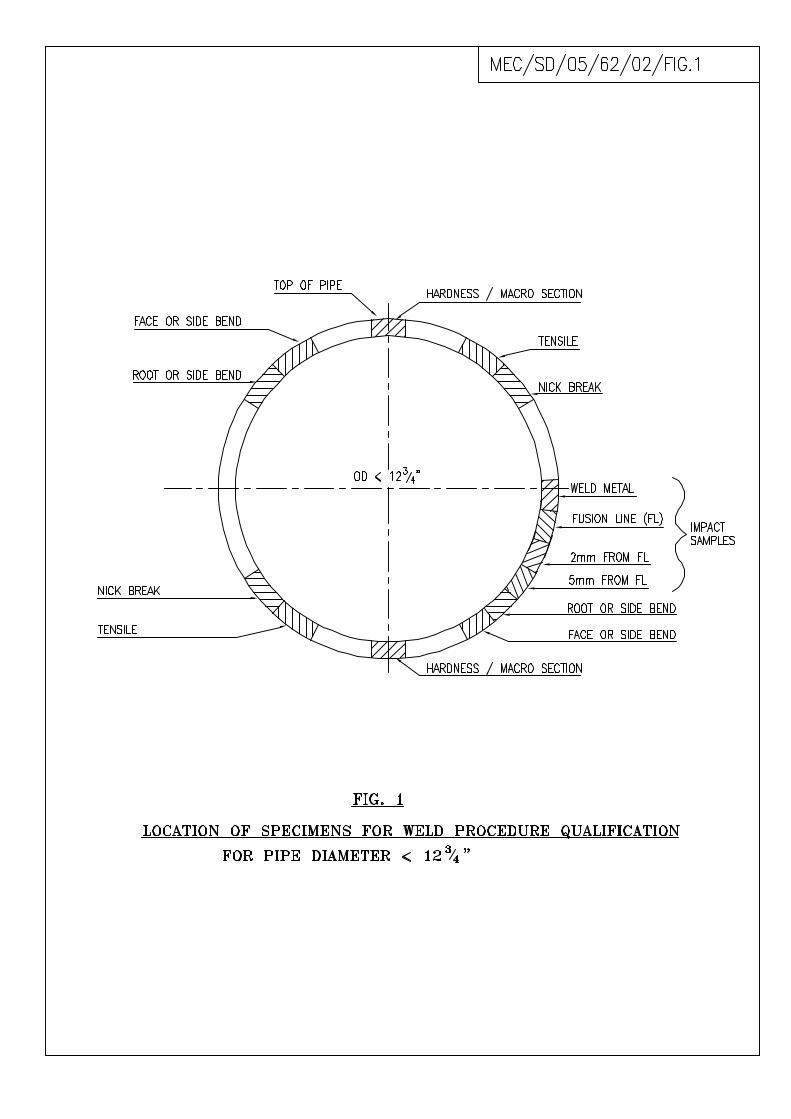

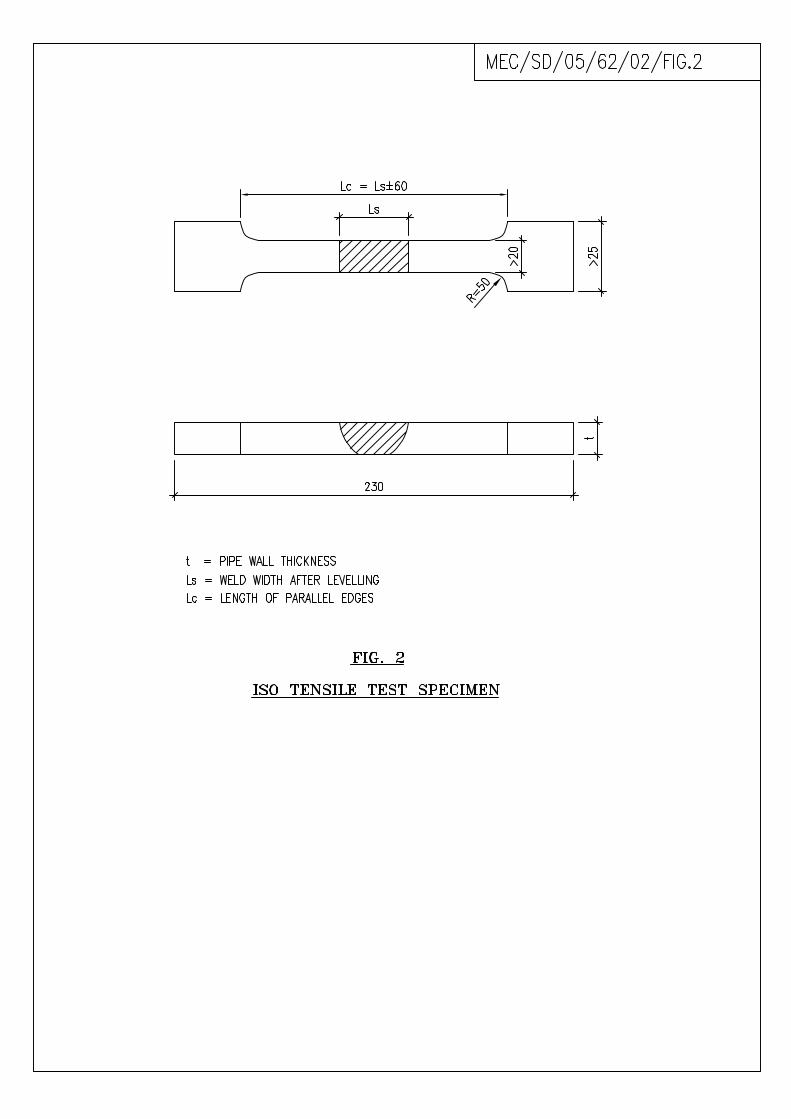
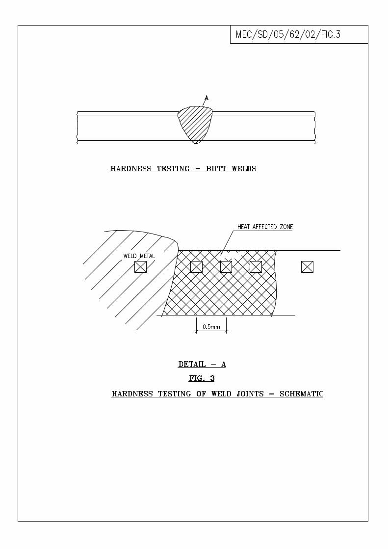

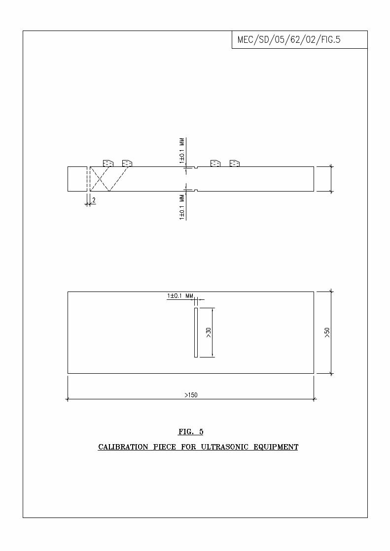
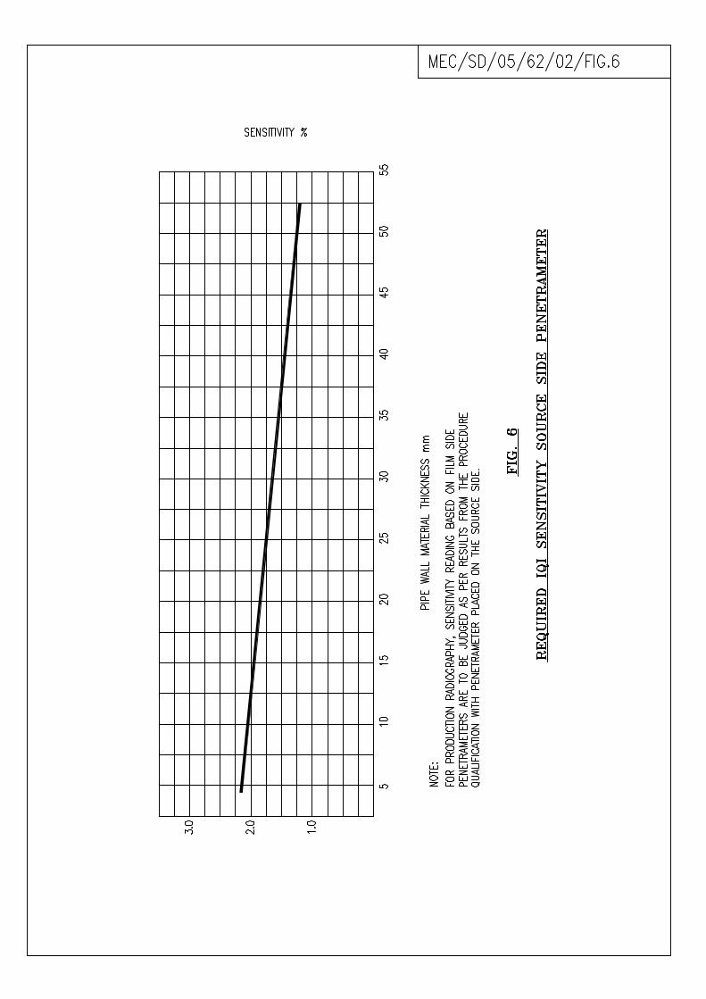
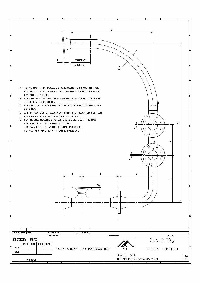
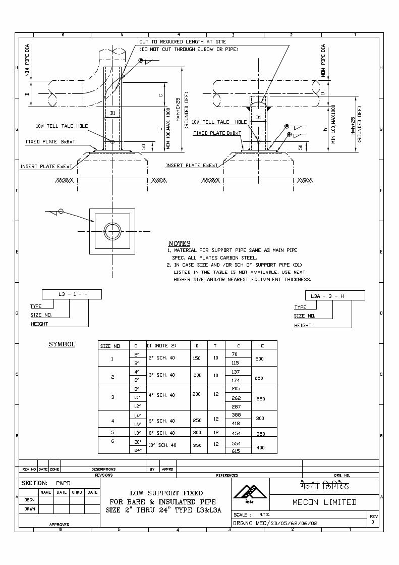
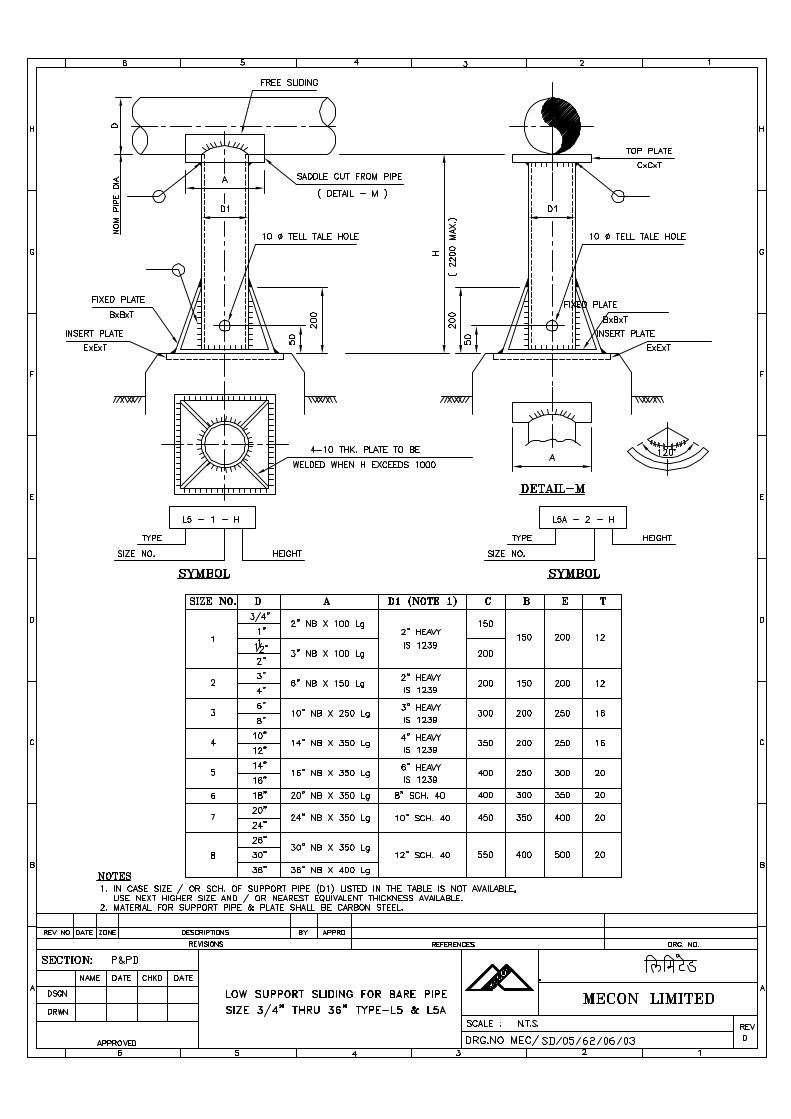
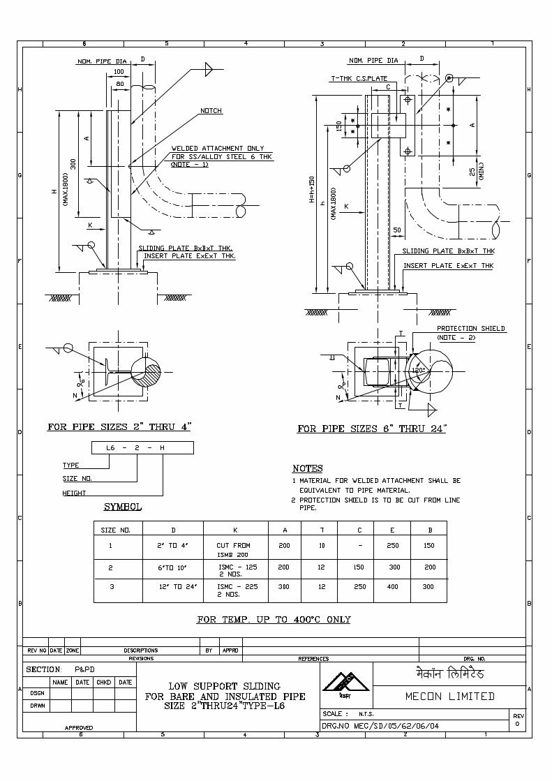
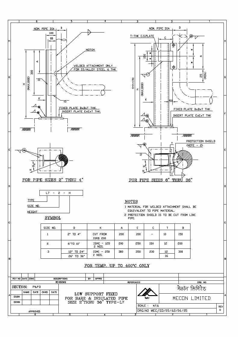
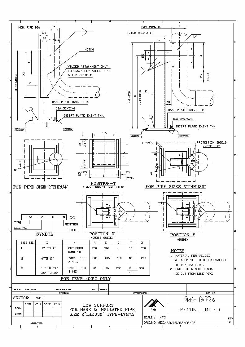
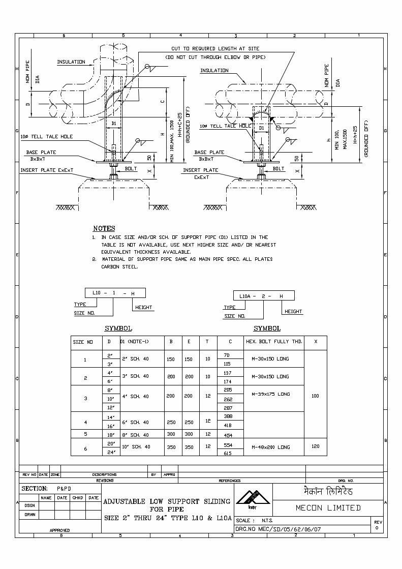
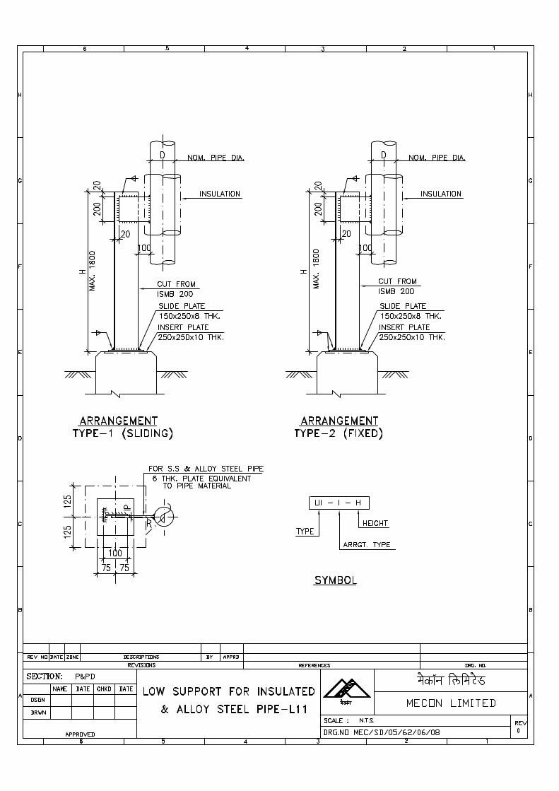
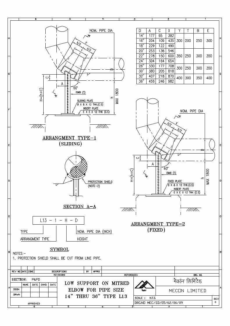
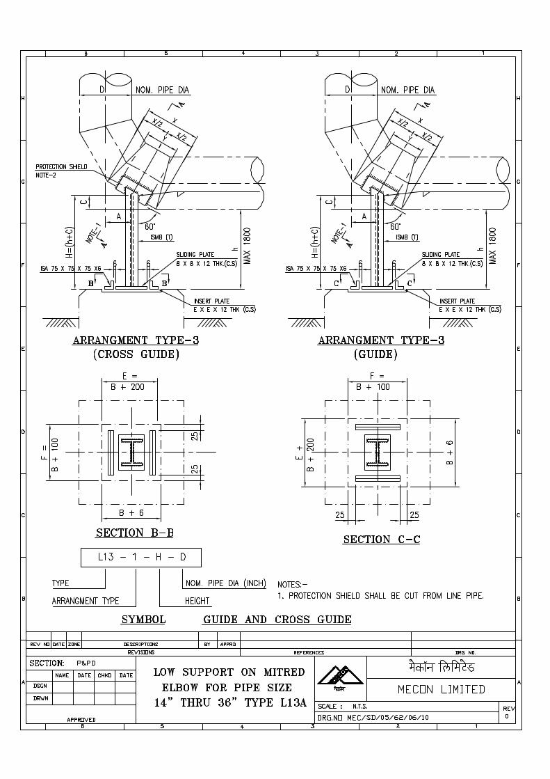
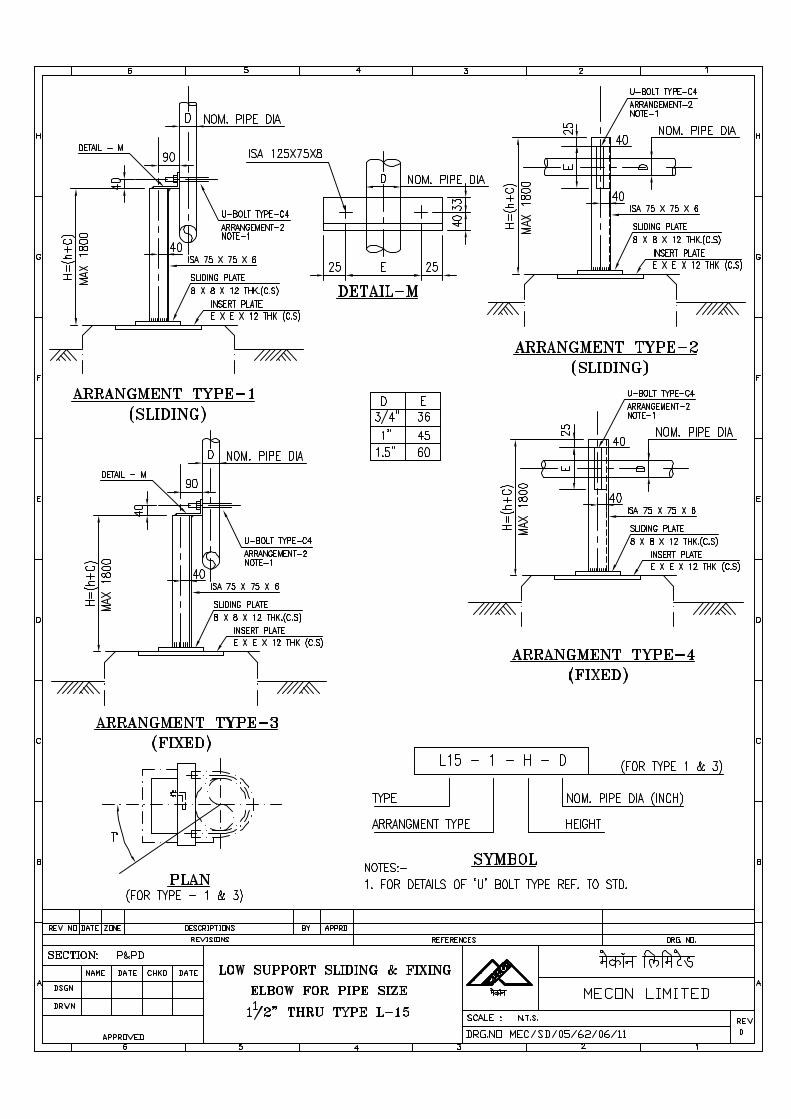
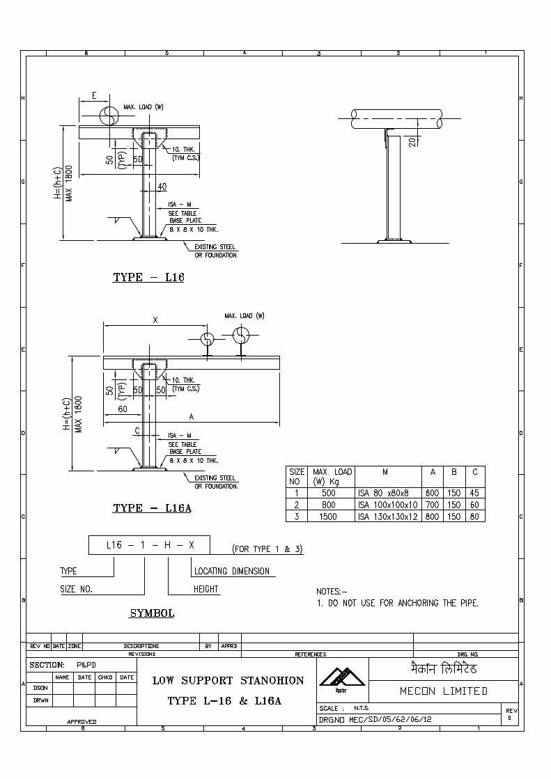
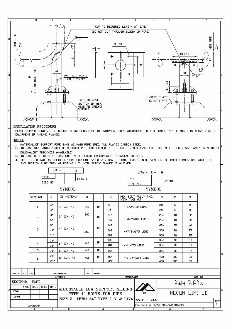
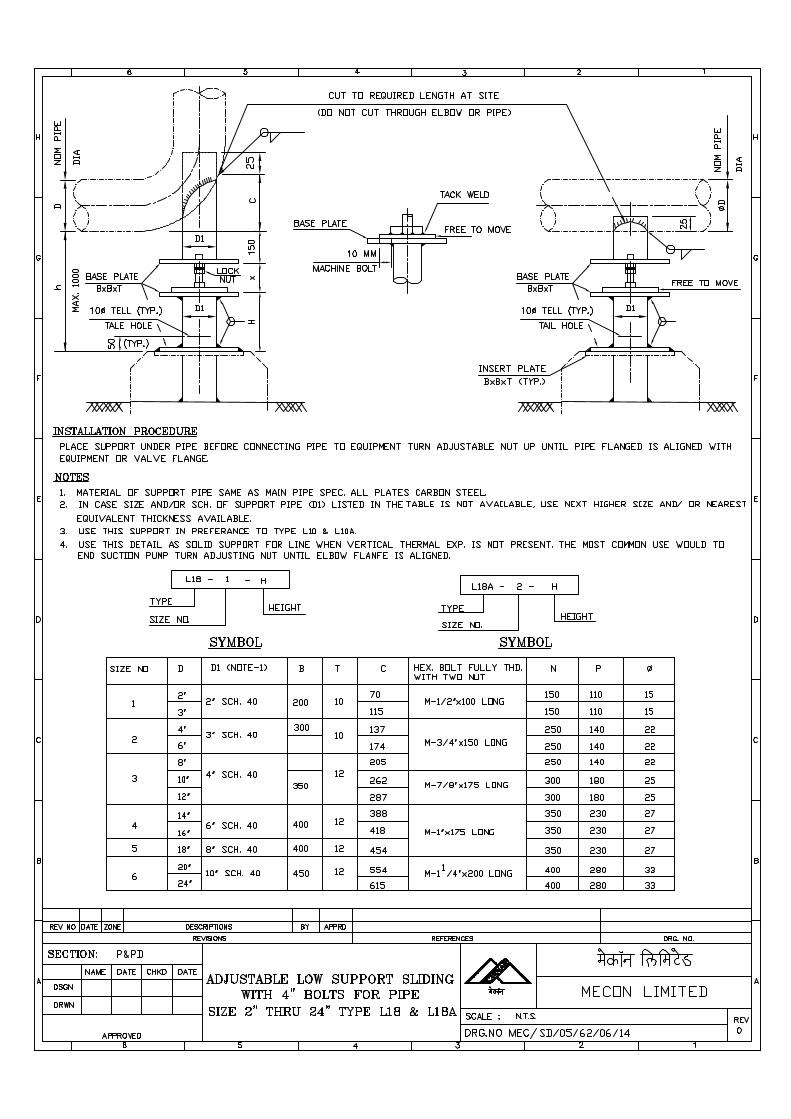
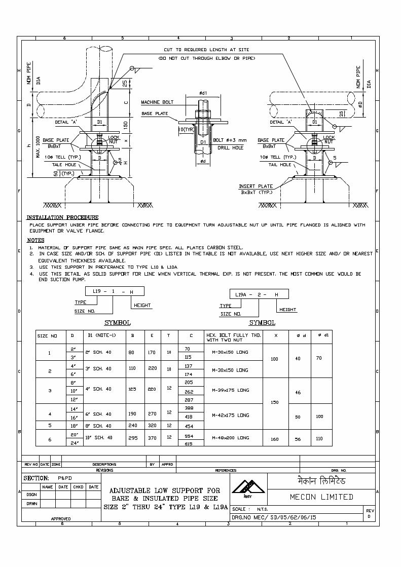
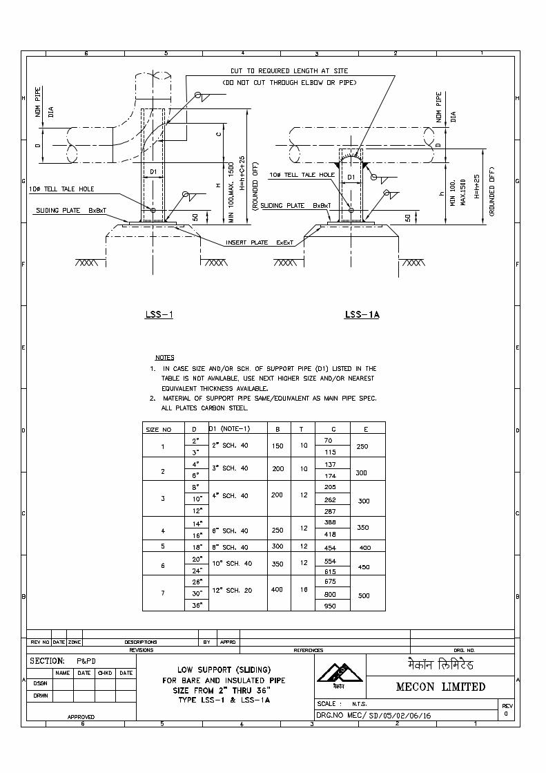
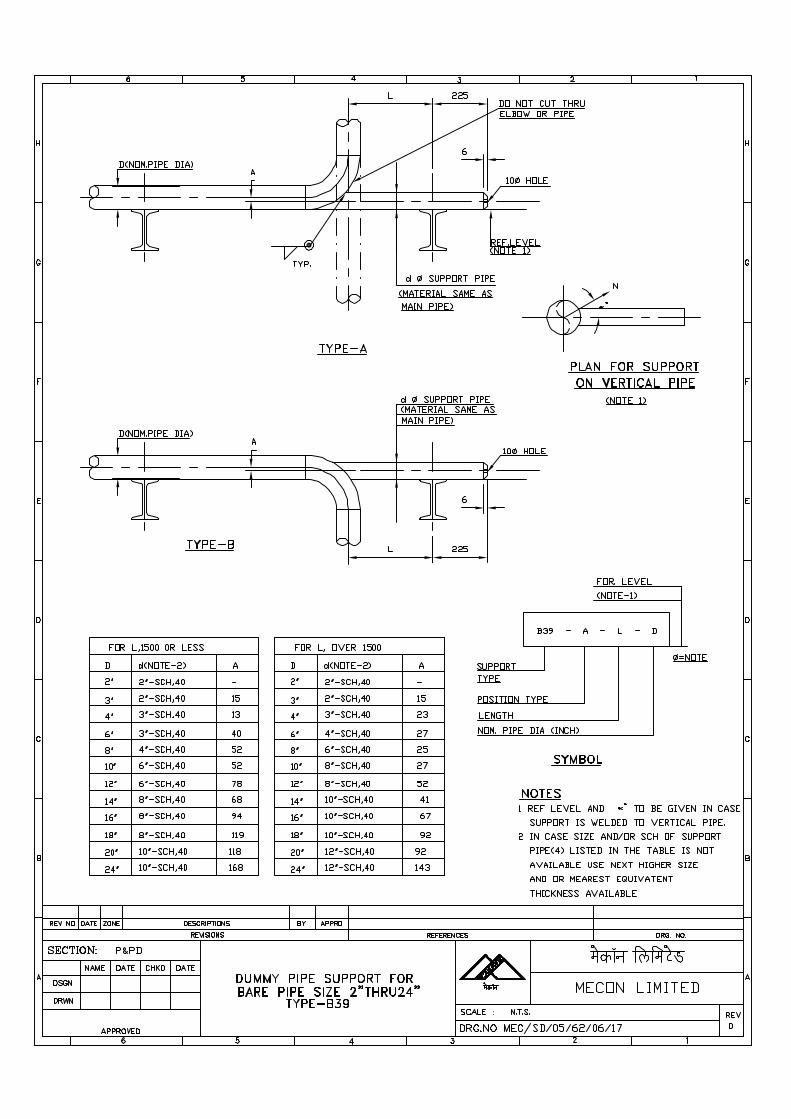
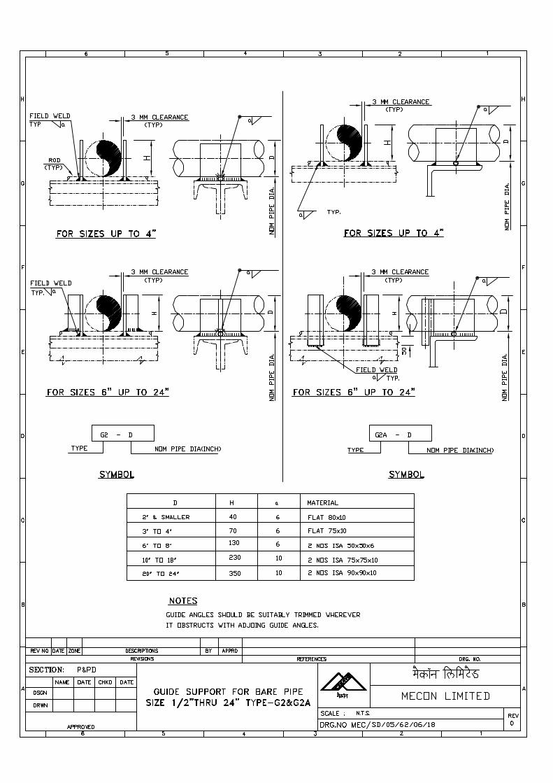
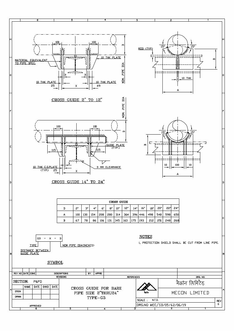
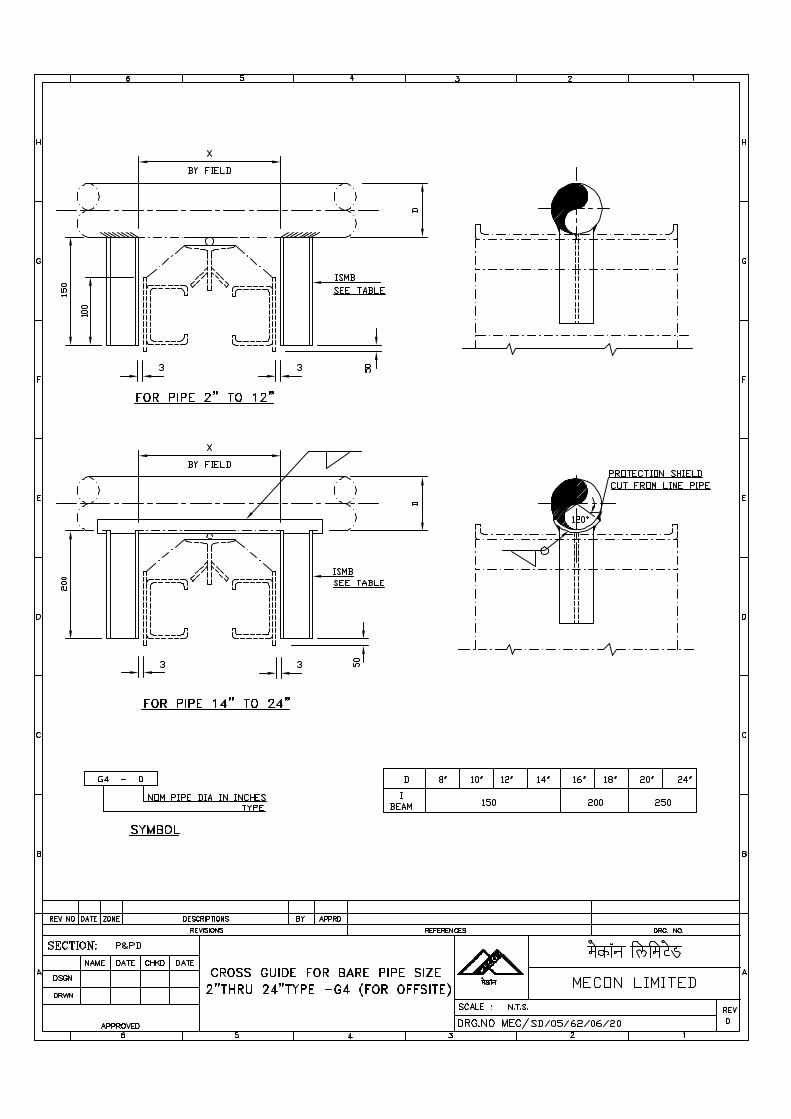
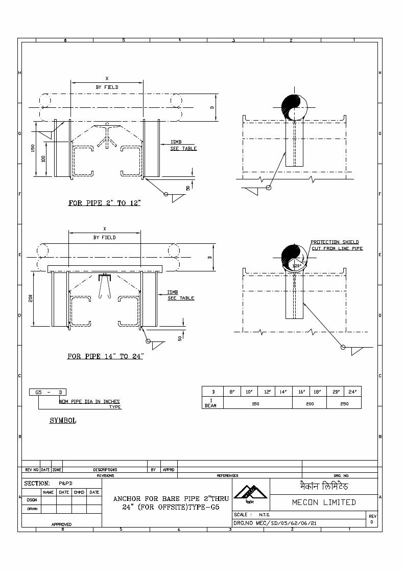
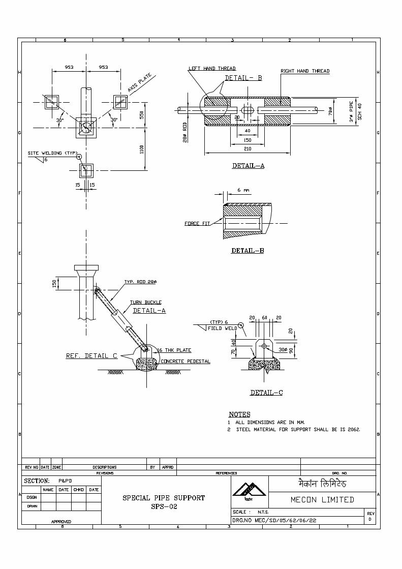
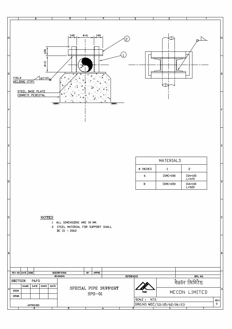

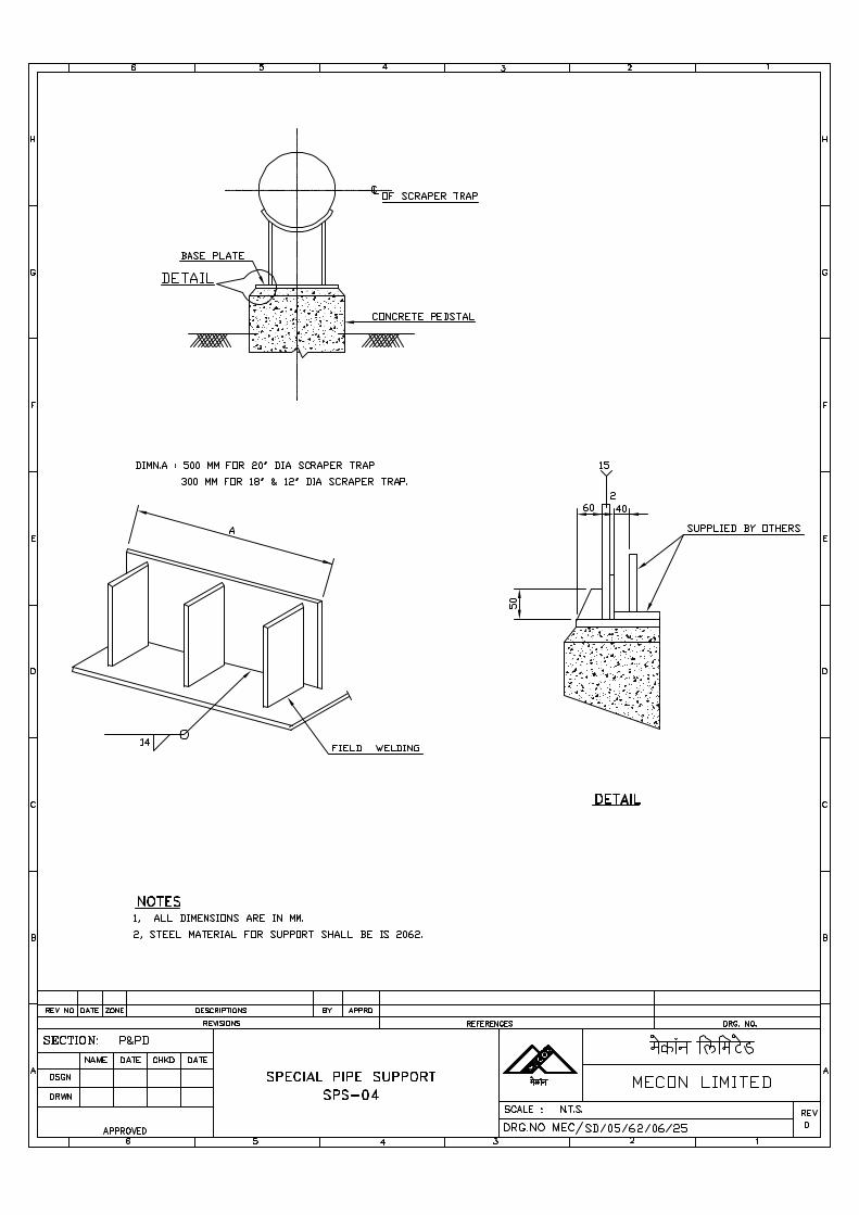
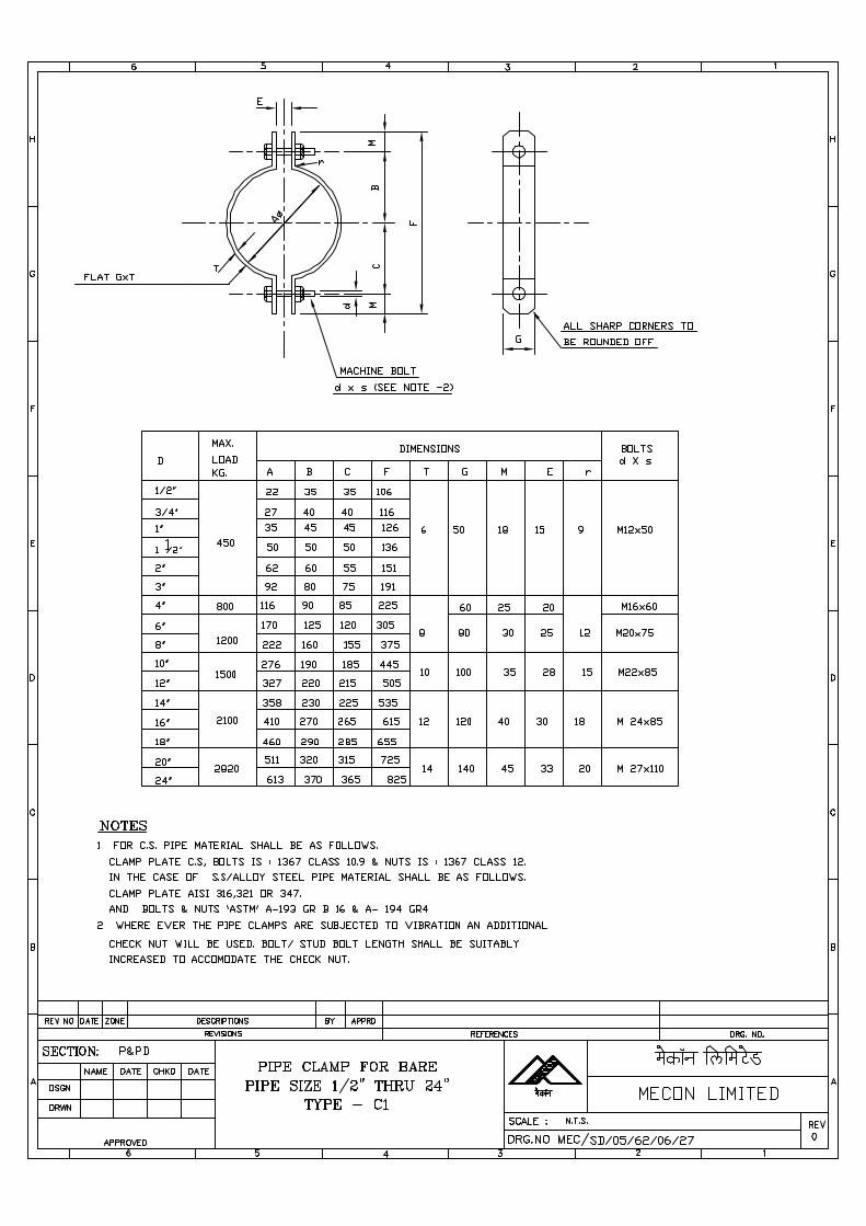
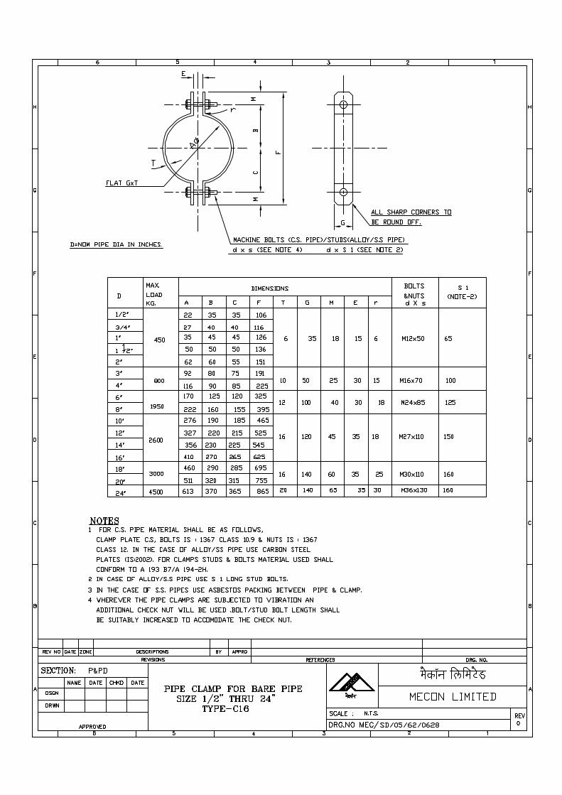
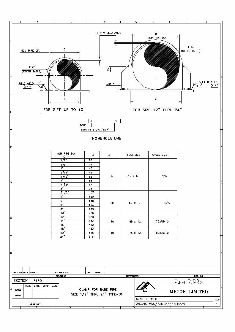
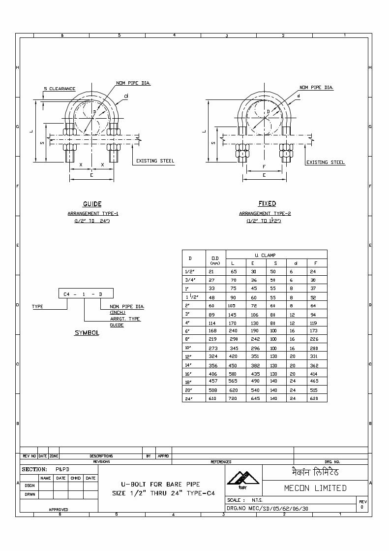

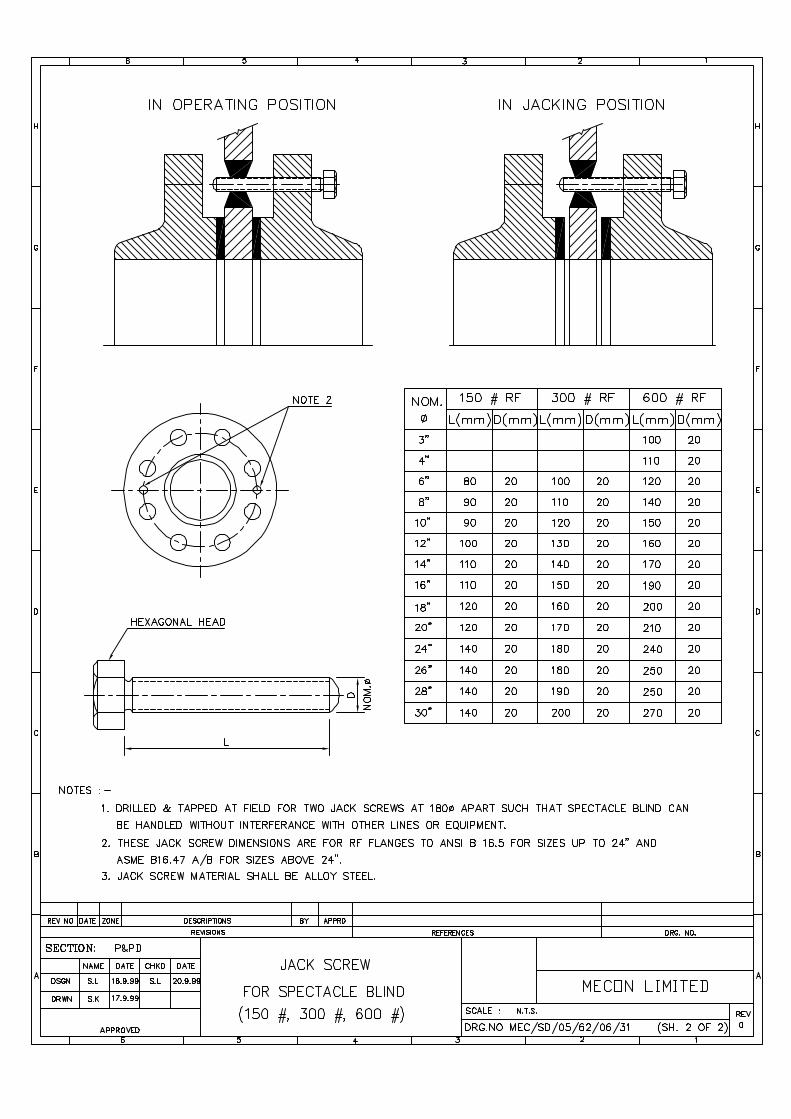
SPECIFICATIONFOR
SHOP & FIELD PAINTING
SPECIFICATION NO. MEC/S/05/62/07A
(PROCESS & PIPELINE DESIGN SECTION)MECON LIMITED
DELHI - 110 092
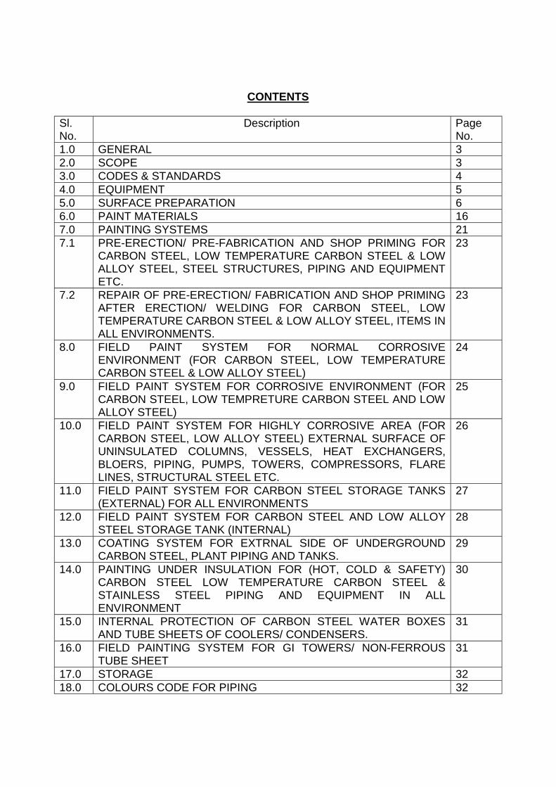
CONTENTS
Sl.No.
Description PageNo.
1.0 GENERAL 32.0 SCOPE 33.0 CODES & STANDARDS 44.0 EQUIPMENT 55.0 SURFACE PREPARATION 66.0 PAINT MATERIALS 167.0 PAINTING SYSTEMS 217.1 PRE-ERECTION/ PRE-FABRICATION AND SHOP PRIMING FOR
CARBON STEEL, LOW TEMPERATURE CARBON STEEL & LOWALLOY STEEL, STEEL STRUCTURES, PIPING AND EQUIPMENTETC.
23
7.2 REPAIR OF PRE-ERECTION/ FABRICATION AND SHOP PRIMINGAFTER ERECTION/ WELDING FOR CARBON STEEL, LOWTEMPERATURE CARBON STEEL & LOW ALLOY STEEL, ITEMS INALL ENVIRONMENTS.
23
8.0 FIELD PAINT SYSTEM FOR NORMAL CORROSIVEENVIRONMENT (FOR CARBON STEEL, LOW TEMPERATURECARBON STEEL & LOW ALLOY STEEL)
24
9.0 FIELD PAINT SYSTEM FOR CORROSIVE ENVIRONMENT (FORCARBON STEEL, LOW TEMPRETURE CARBON STEEL AND LOWALLOY STEEL)
25
10.0 FIELD PAINT SYSTEM FOR HIGHLY CORROSIVE AREA (FORCARBON STEEL, LOW ALLOY STEEL) EXTERNAL SURFACE OFUNINSULATED COLUMNS, VESSELS, HEAT EXCHANGERS,BLOERS, PIPING, PUMPS, TOWERS, COMPRESSORS, FLARELINES, STRUCTURAL STEEL ETC.
26
11.0 FIELD PAINT SYSTEM FOR CARBON STEEL STORAGE TANKS(EXTERNAL) FOR ALL ENVIRONMENTS
27
12.0 FIELD PAINT SYSTEM FOR CARBON STEEL AND LOW ALLOYSTEEL STORAGE TANK (INTERNAL)
28
13.0 COATING SYSTEM FOR EXTRNAL SIDE OF UNDERGROUNDCARBON STEEL, PLANT PIPING AND TANKS.
29
14.0 PAINTING UNDER INSULATION FOR (HOT, COLD & SAFETY)CARBON STEEL LOW TEMPERATURE CARBON STEEL &STAINLESS STEEL PIPING AND EQUIPMENT IN ALLENVIRONMENT
30
15.0 INTERNAL PROTECTION OF CARBON STEEL WATER BOXESAND TUBE SHEETS OF COOLERS/ CONDENSERS.
31
16.0 FIELD PAINTING SYSTEM FOR GI TOWERS/ NON-FERROUSTUBE SHEET
31
17.0 STORAGE 3218.0 COLOURS CODE FOR PIPING 32
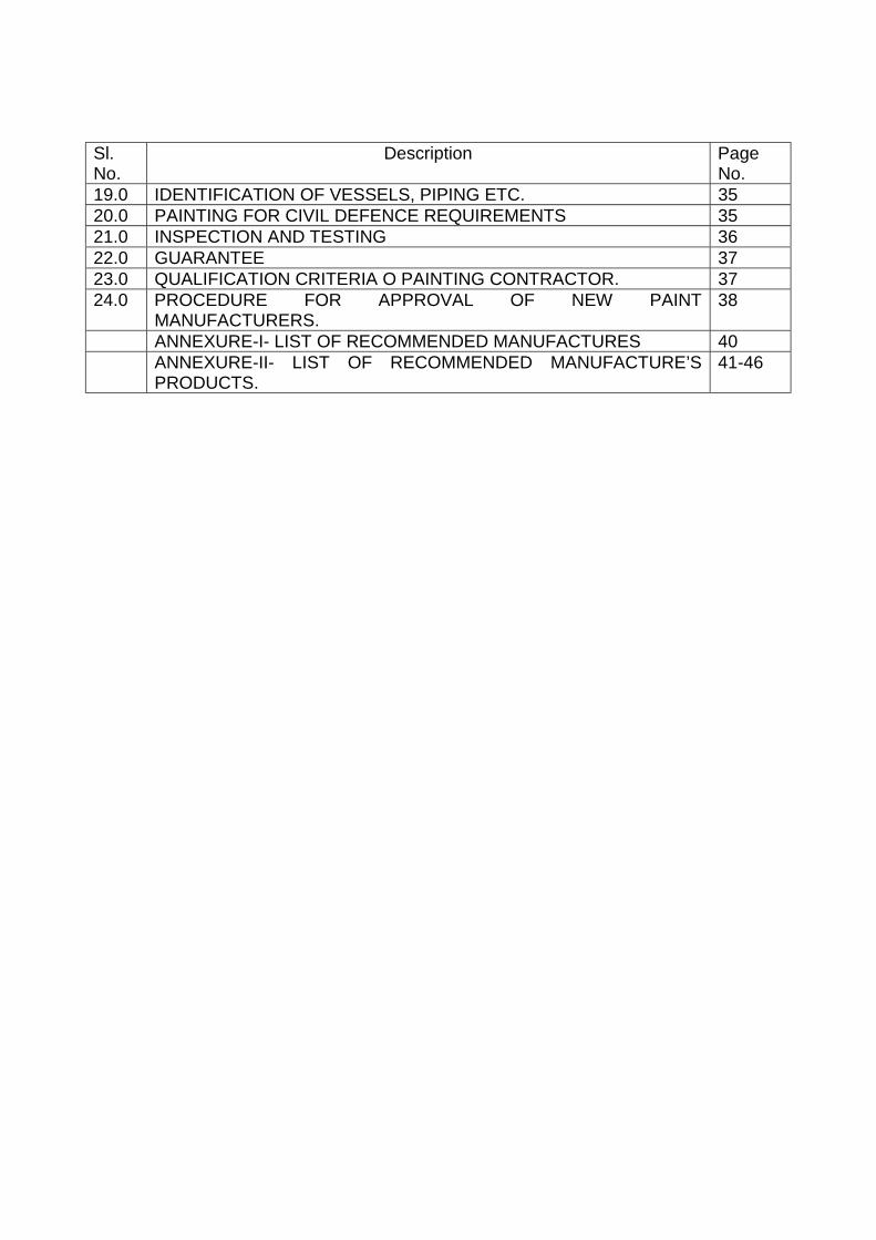
Sl.No.
Description PageNo.
19.0 IDENTIFICATION OF VESSELS, PIPING ETC. 3520.0 PAINTING FOR CIVIL DEFENCE REQUIREMENTS 3521.0 INSPECTION AND TESTING 3622.0 GUARANTEE 3723.0 QUALIFICATION CRITERIA O PAINTING CONTRACTOR. 3724.0 PROCEDURE FOR APPROVAL OF NEW PAINT
MANUFACTURERS.38
ANNEXURE-I- LIST OF RECOMMENDED MANUFACTURES 40ANNEXURE-II- LIST OF RECOMMENDED MANUFACTURE’SPRODUCTS.
41-46
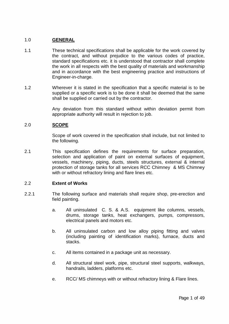
Page 1 of 49
1.0 GENERAL
1.1 These technical specifications shall be applicable for the work covered bythe contract, and without prejudice to the various codes of practice,standard specifications etc. it is understood that contractor shall completethe work in all respects with the best quality of materials and workmanshipand in accordance with the best engineering practice and instructions ofEngineer-in-charge.
1.2 Wherever it is stated in the specification that a specific material is to besupplied or a specific work is to be done it shall be deemed that the sameshall be supplied or carried out by the contractor.
Any deviation from this standard without within deviation permit fromappropriate authority will result in rejection to job.
2.0 SCOPE
Scope of work covered in the specification shall include, but not limited tothe following.
2.1 This specification defines the requirements for surface preparation,selection and application of paint on external surfaces of equipment,vessels, machinery, piping, ducts, steels structures, external & internalprotection of storage tanks for all services RCC Chimney & MS Chimneywith or without refractory lining and flare lines etc.
2.2 Extent of Works
2.2.1 The following surface and materials shall require shop, pre-erection andfield painting.
a. All uninsulated C. S. & A.S. equipment like columns, vessels,drums, storage tanks, heat exchangers, pumps, compressors,electrical panels and motors etc.
b. All uninsulated carbon and low alloy piping fitting and valves(including painting of identification marks), furnace, ducts andstacks.
c. All items contained in a package unit as necessary.
d. All structural steel work, pipe, structural steel supports, walkways,handrails, ladders, platforms etc.
e. RCC/ MS chimneys with or without refractory lining & Flare lines.
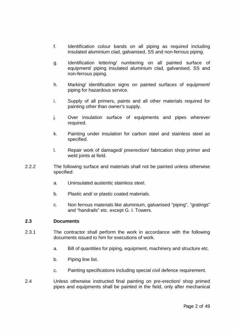
Page 2 of 49
f. Identification colour bands on all piping as required includinginsulated aluminium clad, galvanised, SS and non-ferrous piping.
g. Identification lettering/ numbering on all painted surface ofequipment/ piping insulated aluminium clad, galvanised, SS andnon-ferrous piping.
h. Marking/ identification signs on painted surfaces of equipment/piping for hazardous service.
i. Supply of all primers, paints and all other materials required forpainting other than owner’s supply.
j. Over insulation surface of equipments and pipes whereverrequired.
k. Painting under insulation for carbon steel and stainless steel asspecified.
l. Repair work of damaged/ preerection/ fabrication shop primer andweld joints at field.
2.2.2 The following surface and materials shall not be painted unless otherwisespecified:
a. Uninsulated austentic stainless steel.
b. Plastic and/ or plastic coated materials.
c. Non ferrous materials like aluminium, galvanised “piping”, “gratings”and “handrails” etc. except G. I. Towers.
2.3 Documents
2.3.1 The contractor shall perform the work in accordance with the followingdocuments issued to him for executions of work.
a. Bill of quantities for piping, equipment, machinery and structure etc.
b. Piping line list.
c. Painting specifications including special civil defence requirement.
2.4 Unless otherwise instructed final painting on pre-erection/ shop primedpipes and equipments shall be painted in the field, only after mechanical
Page 3 of 49
completion and testing on system are completed as well as, aftercompletion of steam purging wherever required.
2.5 Changes and deviations required for any specific job due to clientsrequirement or otherwise shall be referred to EIL for deviation permit.
3.0 CODES & STANDARDS
3.1 Without prejudice to the provision of clause 1.1 above and the detailedspecifications of the contract, the following codes and standards shall befollowed for the work covered by this contract.
IS:5 : Colour coding
IS-101 : Methods of test for ready mixed paintand enamels.
IS-2379:1990 : Indian standard for pipe lineIdentification –Colour code.
ASTM : American standard test methods forPaints and coatings.
ASA A 13.1-1981 : Scheme for Identification of pipingSystems : American National StandardInstitution.
3.2 Surface Preparation Standards:
Following standards shall be followed for surface preparations:
3.2.1 Swedish Standard : SIS-05 5900-1967/ ISO-8501-1-1998(Surface preparation standards for painting steel surfaces).
This standard contains photographs of the various standards on fourdifferent degrees of rusted steel and as such is preferable for inspectionpurpose by the Engineer-in-Charge.
3.2.2 Steel structure painting Council, U.S.A (surface preparationsspecifications (SSPC-SP).
3.2.3 British standard (surface finish or Blast-cleaned for painting) BS:4232
3.2.4 National Associations of Corrosion Engineers, U.S.A. (NACE)
Page 4 of 49
3.2.5 Various International Standards equivalent to swedish Standard forsurface preparation are given in Table-I.
3.3 The contractor shall arrange, at his own cost, to keep a set of latest editionof any one of the above standards and codes at site.
3.4 The paint manufacturer’s instructions shall be followed as far aspracticable at all times. Particular attention shall be paid to the following:
a. Instructions for storage to avoid exposure as well as extremes oftemperature.
b. Surface preparations prior to painting.
c. Mixing and thinning.
d. Application of paints and the recommended limit on time intervalsbetween coats.
4.0 EQUIPMENT
4.1 All tools, brushes, rollers, spray guns, abrasive materials hand/ powertools for leaning and all equipments, scaffolding materials, shot/ wetabrassive blasting, water blasting equipments & air compressors etc.required to be used shall be suitable for the work and all in good order andshall be arranged by the contractor at site and in sufficient quantity.
Mechanical mixing shall be used for paint mixing operations in case of twopack systems except that the Engineer-in-Charge may allow the handmixing of small quantities at his discretion.
5.0 SURFACE PREPARATION, SHOP COAT, COATING APPLICATION &REPAIR AND DOCUMENTATION
5.1 General
5.1.1 In order to achive the maximum durability, one or more of followingmethods of surface preparation shall be followed, depending on conditionof steel surface and as instructed by Engineer-in-Charge. Adhesion of thepaint film to surface depends largely on the degree of cleanliness of themetal surface. Proper surface preparation contributes more to the successof the paint protective system:
a. Manual or hand tools cleaning.b. Mechanical or power tool cleaning.c. Blast cleaning.
Page 5 of 49
5.1.2 Mill scale, rust, rust scale and foreign matter shall be removed fully toensure that a clean and dry surface is obtained. The minimum acceptablestandard in case of manual or hand tool cleaning shall be St. 2 orequivalent, in case of mechanical or power tool cleaning it shall be St. 3 orequivalent, in case of blast cleaning it shall be Sa 2½ or equivalent as perSwedish Standard SIS-055900-1967/ ISO-8501-1-1988. Where highlycorrosive condition exits, then blast cleaning shall be Sa3 as per SwedishStandard.
Remove all other contaminants, oil, grease etc. by use of an aromaticsolvent prior to surface cleaning.
5.1.3 Blast cleaning shall not be performed where dust can contaminatesurfaces undergoing such cleaning or during humid weather conditionshaving humidity exceeding 85%.
5.1.4 Irrespective of the method of surface preparation, the first coat of primermust be applied on dry surface. This should be done immediately and inany case within 4 hours of cleaning of surface. However, at times ofunfavourable weather conditions, the Engineer-in-Charge shall have theliberty to control the time period, at his sole discretion and / or to insist onrecleaning, as may be required, before primer application is taken up. Ingeneral, during unfavourable weather conditions, blasting and paintingshall be avoided as far as practicable.
5.1.5 The external surface of R.C.C. chimney to be painted be dry and clean.Any loose particle of stand, cement, aggregate etc. shall be removed byrubbing with soft wire brush if necessary, acid etching with 10-15% HCLsolution about 15 minutes shall be carried out and surface must bethorought washed with water to remove acid & loose particles then drycompletely before application of paint.
5.2 Procedure of Surface Preparation.
5.2.1 Blast Cleaning
5.2.1.1 Air Blast Cleaning
The surface shall be blast cleaned using one of the abrasives: AL202particles chilled casts iron or malleable iron and steel at pressure of 7kg.Cm2 at appropriate distance and angle depending on nozzle sizemaintaining constant velocity and pressure. Chilled cast iron, malleableiron and steel shall be in the form of shot or grit of size not greater than0.055” maximum in case of steel and malleable iron and 0.04” maximumin case of chilled iron. Compressed air shall be free form moisture and oil.
Page 6 of 49
The blasting nozzles should be venturei style with tungsten carbide orboron carbide as the material for liners. Nozzles orifice may vary from3/16” to ¾”. On completion of blasting operation, the blasted surface shallbe clean and free from any scale or rust and must show a grey whitemetallic lusture. Primer or first coat of paint shall be applied within 4 hoursof surface preparation. Blast cleaning shall bot be done outdoors in badweather without adequate protection or when there is dew on the metalwhich is to be cleaned, surface profile shall be uniform to provide goodkey to the paint adhesion (i.e.35to 50µ). If possible vacuum collector shallbe installed for collecting the abrasive and recycling.
5.2.1.2 Water Blast cleaning
Environmental, health and safety problems associated with abrassiveblast cleaning limit the application of air blast cleaning in manyinstallations. In such case water blast cleaning is resorted to.
Water blast cleaning can be applied with or without abrassive and high-pressure water blasting. The water used shall be inhibited with sodiumchromate/ phosphate. The blast cleaned surface shall be washedthoroughly with detergents and wiped solvent and dried with compressedAir. For effective cleaning abrassives are used. The most commonly usedpressure for high pressure water blast cleaning for maintenance surfacepreparation is 3000 to 6000 psi at 35-45 liters/ minute water volume andpressure upto 10000 psi and water volume of 45 liters/ minute providemaximum cleaning.
The wate blast cleaned surface shall be comparable to SSPC-SP-12/NACE No. 5. The operation shall be carried out as per SSPC guidelinesfor water blast cleaning. The indicative values for sand injection is
Air : 300 to 400 Cu.ft/ min.Water : 5-10 liter/ min. with corrosion inhibitorSand : 200-400 lbs/ hr.Nozzle : 0.5 to 1” diaSpecial equipments for water blast cleaning with abrasives now availableshall be used.
5.2.2 Mechanical of Power tool cleaning
Power tool cleaning shall be done mechanical striking tools, chippinghammers, griding wheels or roating steels wire-brushes. Excessiveburnish of surface shall be avoided as it can reduce paint adhesion. Oncompletion of cleaning, the detached rust mill scale etc. shall be removedby clean rags and/ or washed by water or stream and thoroughly driedwith compressed air jet before application of paint.
Page 7 of 49
5.2.3 Maual or hand tool cleaning
Manual or hand tool cleaning is used only where safety problems limit theapplication of other surface preparation procedure and hence dones notappear in the specifications of paint systems.
Hand tool cleaning normally consists of the following:
a. Hand descaling and/ or hammeringb. Hand scrapingc. Hand wire brushing
Rust, mill scale spatters, old coating and other foreign matter, shall beremoved by hammering, scrapping tools, emery paper cleaning, wirebrushing or combination of the above methods. On completion ofcleaning, loose materials shall be removed from the surface by clean ragsand the surface shall be brushed, swept, deducted and blown off withcompressed air/ steam to remove all loose matter. Finally the surface maybe washed with water and dried for effective cleaning.
5.3 Non compatible shop coat primer
The compatibility of finishing coat should be confirmed from the paintmanufacturer. In the event of use of primer such as zinc rich epoxy,inorganic zinc silicate etc. as shop coat the pant system shall depend oncondition of shop coat, if shop coat is in satisfactory condition showing nomajor defects, the shop coat shall not be removed. The touch up primerand finishing coat(s) shall be identified for application by Engineer-in-Charge.
5.4 Shop coated (coated with primer & finishing coat) equipment should notbe repainted unless paint is damaged.
5.5 Shop primed equipment and surface will only be ‘spot cleaned’ indamaged areas by means of power tool brush cleaning and then spotprimed before applying one coat of filed primer unless otherwise specified.If shop primer is not compatible with field primer then shop coated primershould be completely removed before applications of selected paintssystem for particular environment.
5.6 For packaged units/ equipment, shop primer should be as per the paintsystem given in this specification. However, manufacturer’s standard canbe followed after review.
5.7 Coating Procedure and Application:
Page 8 of 49
5.7.1 Surface shall not be coated in rain, wind or in environment where injuriousairbone elements exists, when the steel surface temperature is less than5° F above dew point when the relative humidity is greater then 85% orwhen the temperature is below 40° F.
5.7.2 Blast cleaned surface shall be coated with one complete application ofprimer as soon as practicable but in no case later than 4 hrs. the sameday.
5.7.3 To the maximum extent practicable, each coat of material shall be appliedas a continuous film uniform thickness free of probes. Any spots or areasmissed in application shall be recoated and permitted to dry before thenext coat is applied. Applied paint should have the desired wet filmthickness.
5.7.4 Each coat shall be proper state of cure or dryness before the applicationof succeeding coat. Material shall be considered dry for recoating when anadditional coat can applied without the development of any detrimentalfilm irregularities such as lifting or loose of adhesion of the under coat.Manufacturer instruction shall be followed for intercoat interval.
5.7.5 When the successive coat of the same colour have been specified,alternate coat shall be tinted, when practical, sufficiently to produceenough contrast to indicate complete coverage of the surface. The tintingmaterial shall be compatible with the material and not detrimental to itsservice life.
5.7.6 Air spray application shall be in accordance with the following:
a. The equipment used shall be suitable for the intended purpose,shall be capable of properly atomizing the paint to be applied, andshall be equipped with suitable pressure regulators and gauges.The air caps, nozzles, and needles shall be those recommended bythe manufacturer of the equipment for the material beign sprayed.The equipment shall be kept in satisfactory condition to permitproper paint application.
b. Traps or separators shall be provided to remove oil and condensedwater from the air. These traps or separators must be of adequatesize and must be drained periodically during operations. The airfrom the spray gun impinging against the surface shall showcondensed water or oil.
Page 9 of 49
c. Ingredients shall be kept properly mixed in the spray pots orcontainers during application by continuous mechanicalagitation.
d. The pressure on the material in the pot and of the air at the gunshall be adjusted for optimum spraying effectiveness. The pressureon the material in the pot shall be adjusted when necessary forchange in elevation of the gun above the pot. The atomizing airpressure at the gun shall be high enough to properly atomize thepaint but not so high as to cause excessive fogging of paint,excessive evaporation of solvent, or less by overspray.
e. Spray equipment shall be kept sufficiently clean so that dirt, driedpaint, and other foreign materials are not deposited in the paint film.
Any solvents left in the equipment shall be completely removedbefore applying paint to the surface begin painted.
f. Paint shall be applied in a uniform layer, with overlapping at theedge of the spray pattern. The spray patterns shall be adjusted sothat the paint is deposited uniformly. During application the gunshall be held perpendicular to the surface and at a distance whichwill ensure that a wet layer of paint is deposited on the surface. Thetrigger of the gun should be released at the end of each stroke.
g. All runs and sags shall be brushed out immediately or the paintshall be removed and the surface repainted.
h. Areas inaccessible to the spray gun shall be painted by brush: if notaccessible by brush, daubers or sheepking shall be used.
i. All nameplates, manufacturer’s identification tags, machinedsurface instrument glass, finished flange faces, control valve itemsand similar items shall be masked to prohibit coating disposition. Ifthese surface are coated, the component shall be cleaned andrestored to its original condition.
j. Edges of structural shapes and irregular coated surface shall becoated first and an extra pass made later.
k. If spray gun shown choking, immediately dechoking procedure shallbe followed.
5.7.7 Airless spray application shall be in accordance with the followingprocedure: as per steel structure paint manual vol. 1 & vol. 2. By SSPC,U.S.A., Air less spray relies on hydraulic pressure rather than air
Page 10 of 49
atomization to produce the desired spray. An air compressor or electricmotor is used to operate a pump to produce pressures of 1,000 to 6.000psi. Paint is delivered to the spray gun at this pressure through a singlehose within the gun, a single paint stream is divided into separatestreams, which are forced through a small orifice resulting in atomizationof paint without the use of air. This result in more repaid coverage withless overspray. Airless spray usually is faster, cleaner, more economicaland easier to use than conventional airspray.
Airless spray equipment is mounted on wheels, and paint is aspirated in ahose that sucks paint from any container, including drums. The unit shallhave in built agitator that keep the paint uniformly mixed during thespraying. The unit shall consists of in built strainer. Usually very smallquantities of thinning is required before spray. Incase of High Build epoxycoating (two pack), 30:1 pump ratios and 0.020-0.023” tip size will providea good spray pattern. Ideally fluid hoses should no be less than 3/8” IDand not longer than 50ft to obtain optimum results.
In case of gun choking, decoking steps shall be followed immediately.
5.7.8 Brush application of paint shall be in accordance with the following:
a. Brushes shall be of a style and quality that will enable properapplication of paint
b. Round or oval brushes are most suitable for rivets, bolts, irregularsurfaces and rough or pitted steel. Wide flat brushes are suitablefor large flat areas, but they shall not have width over five inches.
c. Paints shal be applied into all corners.
d. Any runs or sags shall be brushed out.
e. There shall be minimum of brush marks left in the applied paint
f. Surface not accessible to brushes shall be painted by spray,duubers, or sheepkin.
5.7.9 Manual application by sling (where 6 O’ clock position of pipe is notapproachable)
A canvas strip (alternatively a tinplate strip) about 450mm wide and 1.5mlongs is hold under the pipe by two men. Liquid coating poured on thesling at each side of the pipe. The men holding this sling move it up anddown and walk slowly forward while fresh coating is poured on the pipeand they manipulate the sling so that an even coating is ontained all round
Page 11 of 49
the bottom. This work shall be done vey carefully and by experiencedpersonnel. There shall bot be any formation of “Whiskers” and holes in thecoating. The coating film shall be inspected by mirror.
5.7.10 For each coat the painter should know the WFT corresponding to thespecified DFT and standardise the paint application technique to achievethe desired WFT. This is to be ensured in the qualification trial.
5.8 Drying of Coated Surface
5.8.1 No coat shall be applied unit the preceding coat has dried. The materialshall be considered dry for re-coating when another coat can be appliedwithout the development of any film irregularities such as lifting or loss ofadhesion of undercoats. Drying time of the applied coat should not excedmaximum specified for it as a first coat; if it exceeds the paint material haspossible deteriorated or mixing is faulty.
5.8.2 No paint shall be force dried under condition which will cause checking,wrinkling blistering formation of pores, or detrimentally after the conditionof the paint.
No drier shall be added to a paint on the job unless specifically called forin the manufacturer’s specification for the paint.
Paint shall be protected from rain, condensation, contamination snow andfreezing until dry to the fullest extent practicable.
5.9 Repair of damaged paint surface.
5.9.1. Where paint has been damaged in handling and in transportation, therepair of damaged coating of pre-creation/ fabrication shall be as givenbelow.
5.9.2. Repair of damaged inorganic zinc silicate primer after erection/ weldding:
Quickly remove the primer from damaged area by mechanical scrapingand emery paper to expose the white metal. Blasts clean the surfacespossible. Feather the primer over the intact adjacent surface surroundingthe damaged area by emery paper.
5.9.3 Repair of damaged pre-erection and shop priming in the designtemperature of 90° C to 500° C.
- Surface preparation shall be done as per procedure 5.9.2
Page 12 of 49
- One coat of F-9 shall be applied wherever damaged was observedon pre-erection/ pre-fabrication/ shop primer of inorganic zincsilicate coating (F-9) shall not be applied if damaged area is notmore than 5 x 5 cm.
5.10 PAINT APPLICATION
5.10.1 Shop priming/ pre-erection priming with F9 of F12 shall be done only onblasted surface.
5.10.2 Shop priming/ pre-erection priming with F-9 or F-12 shall be done onlywith airless spray.
5.10.3 For large flat surface field painting shall be done by airless sprayotherwise brush can be used.
5.11 Documentation.
1. A written quality plan with procedure for qualification trials and for theactual work.
2. Daily progress report with dedtails of weather condition, particular ofapplication no of coats and type of materials applied, anomolies, progressof work versus programme.
3. Result of measurement of temperature relative humidity, surface profile,film thickness, holiday detection, adhesion tests with signature ofappropriate authority.
4. Particular of surface preparation and paint application during trials andduring the work.
5. Details of non-compliance, rejects and repairs.6. Type of testing equipments and calibration.7. Code and batch numbers of paint material used.
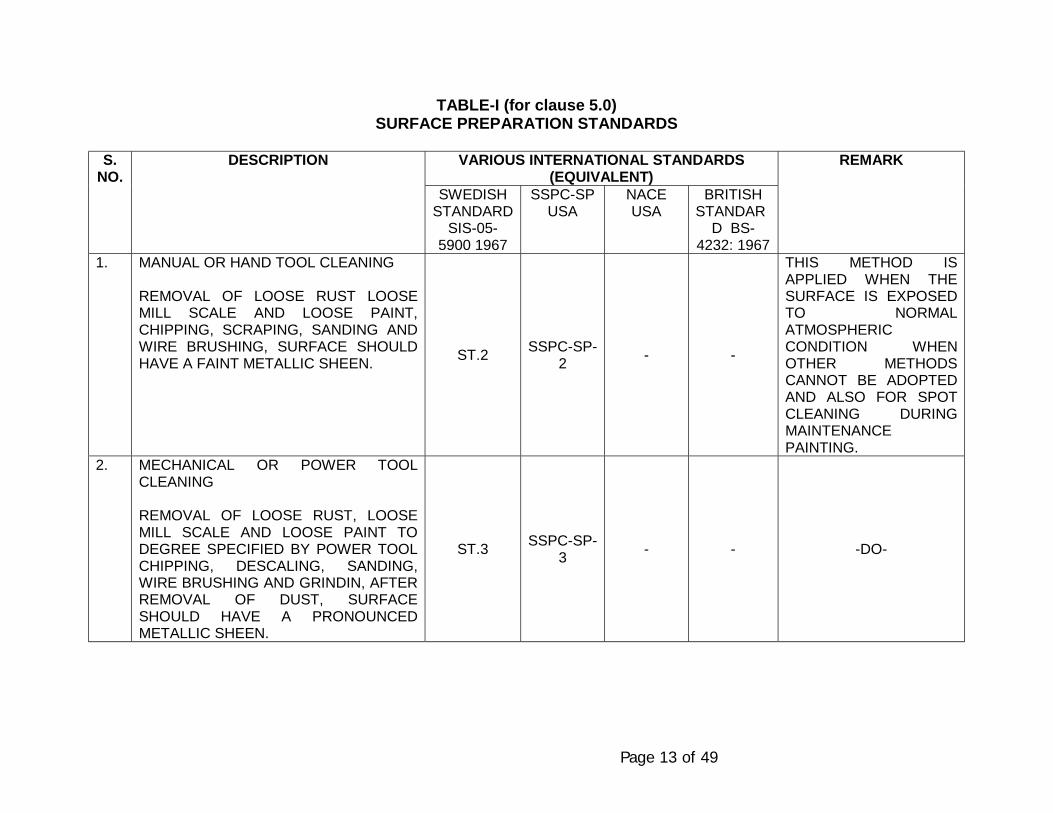
Page 13 of 49
TABLE-I (for clause 5.0)SURFACE PREPARATION STANDARDS
VARIOUS INTERNATIONAL STANDARDS(EQUIVALENT)
S.NO.
DESCRIPTION
SWEDISHSTANDARD
SIS-05-5900 1967
SSPC-SPUSA
NACEUSA
BRITISHSTANDAR
D BS-4232: 1967
REMARK
1. MANUAL OR HAND TOOL CLEANING
REMOVAL OF LOOSE RUST LOOSEMILL SCALE AND LOOSE PAINT,CHIPPING, SCRAPING, SANDING ANDWIRE BRUSHING, SURFACE SHOULDHAVE A FAINT METALLIC SHEEN. ST.2 SSPC-SP-
2 - -
THIS METHOD ISAPPLIED WHEN THESURFACE IS EXPOSEDTO NORMALATMOSPHERICCONDITION WHENOTHER METHODSCANNOT BE ADOPTEDAND ALSO FOR SPOTCLEANING DURINGMAINTENANCEPAINTING.
2. MECHANICAL OR POWER TOOLCLEANING
REMOVAL OF LOOSE RUST, LOOSEMILL SCALE AND LOOSE PAINT TODEGREE SPECIFIED BY POWER TOOLCHIPPING, DESCALING, SANDING,WIRE BRUSHING AND GRINDIN, AFTERREMOVAL OF DUST, SURFACESHOULD HAVE A PRONOUNCEDMETALLIC SHEEN.
ST.3 SSPC-SP-3 - - -DO-
Page 14 of 49
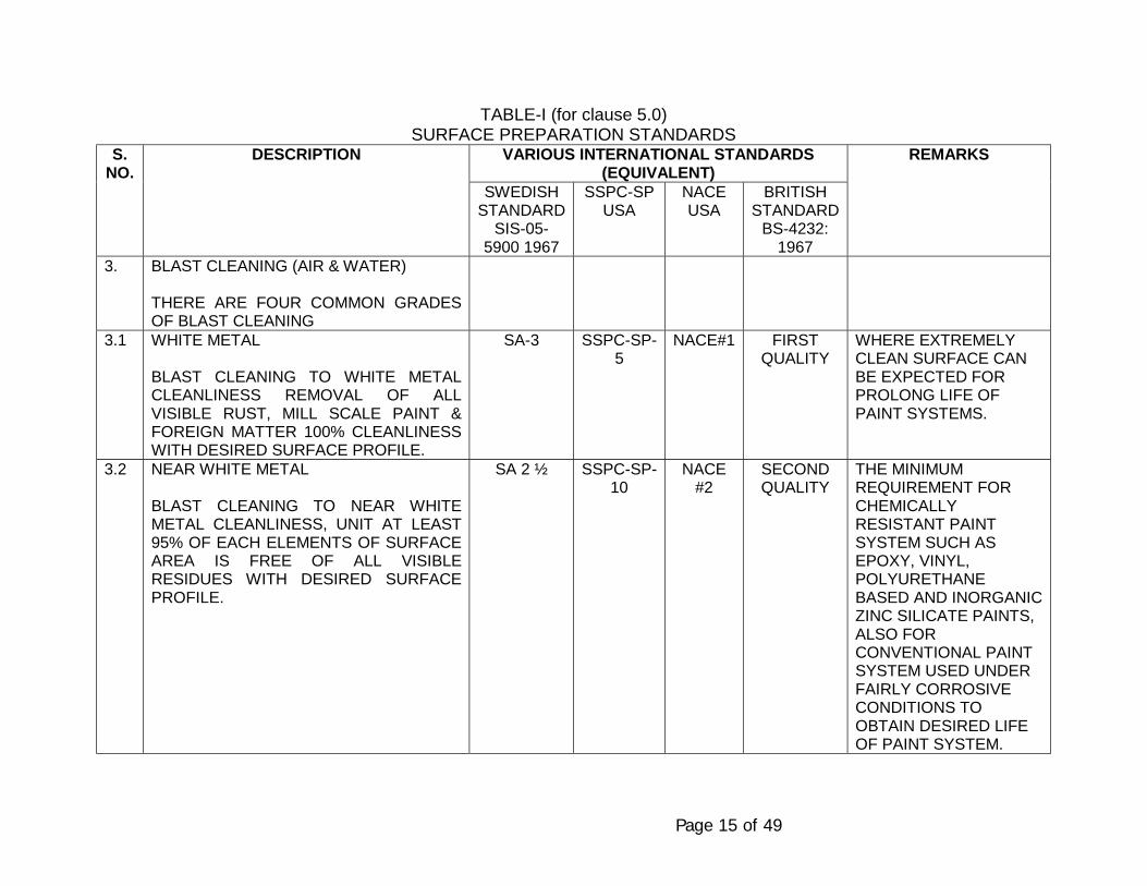
Page 15 of 49
TABLE-I (for clause 5.0)SURFACE PREPARATION STANDARDS
VARIOUS INTERNATIONAL STANDARDS(EQUIVALENT)
S.NO.
DESCRIPTION
SWEDISHSTANDARD
SIS-05-5900 1967
SSPC-SPUSA
NACEUSA
BRITISHSTANDARD
BS-4232:1967
REMARKS
3. BLAST CLEANING (AIR & WATER)
THERE ARE FOUR COMMON GRADESOF BLAST CLEANING
3.1 WHITE METAL
BLAST CLEANING TO WHITE METALCLEANLINESS REMOVAL OF ALLVISIBLE RUST, MILL SCALE PAINT &FOREIGN MATTER 100% CLEANLINESSWITH DESIRED SURFACE PROFILE.
SA-3 SSPC-SP-5
NACE#1 FIRSTQUALITY
WHERE EXTREMELYCLEAN SURFACE CANBE EXPECTED FORPROLONG LIFE OFPAINT SYSTEMS.
3.2 NEAR WHITE METAL
BLAST CLEANING TO NEAR WHITEMETAL CLEANLINESS, UNIT AT LEAST95% OF EACH ELEMENTS OF SURFACEAREA IS FREE OF ALL VISIBLERESIDUES WITH DESIRED SURFACEPROFILE.
SA 2 ½ SSPC-SP-10
NACE#2
SECONDQUALITY
THE MINIMUMREQUIREMENT FORCHEMICALLYRESISTANT PAINTSYSTEM SUCH ASEPOXY, VINYL,POLYURETHANEBASED AND INORGANICZINC SILICATE PAINTS,ALSO FORCONVENTIONAL PAINTSYSTEM USED UNDERFAIRLY CORROSIVECONDITIONS TOOBTAIN DESIRED LIFEOF PAINT SYSTEM.
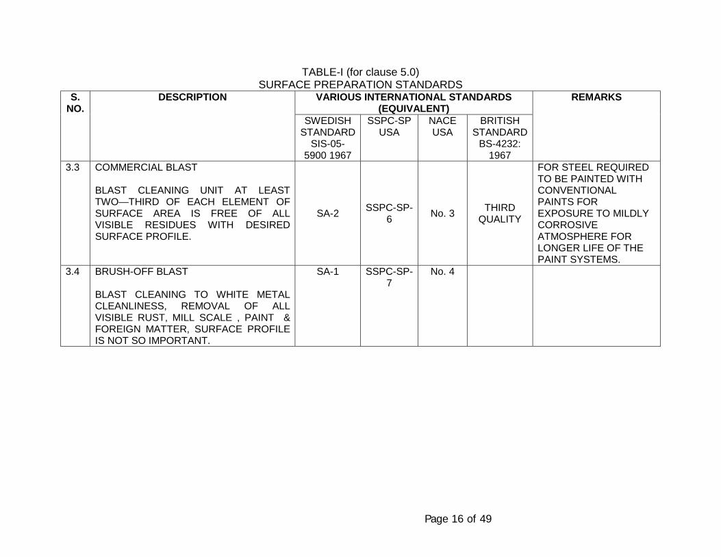
Page 16 of 49
TABLE-I (for clause 5.0)SURFACE PREPARATION STANDARDS
VARIOUS INTERNATIONAL STANDARDS(EQUIVALENT)
S.NO.
DESCRIPTION
SWEDISHSTANDARD
SIS-05-5900 1967
SSPC-SPUSA
NACEUSA
BRITISHSTANDARD
BS-4232:1967
REMARKS
3.3 COMMERCIAL BLAST
BLAST CLEANING UNIT AT LEASTTWO—THIRD OF EACH ELEMENT OFSURFACE AREA IS FREE OF ALLVISIBLE RESIDUES WITH DESIREDSURFACE PROFILE.
SA-2 SSPC-SP-6 No. 3 THIRD
QUALITY
FOR STEEL REQUIREDTO BE PAINTED WITHCONVENTIONALPAINTS FOREXPOSURE TO MILDLYCORROSIVEATMOSPHERE FORLONGER LIFE OF THEPAINT SYSTEMS.
3.4 BRUSH-OFF BLAST
BLAST CLEANING TO WHITE METALCLEANLINESS, REMOVAL OF ALLVISIBLE RUST, MILL SCALE , PAINT &FOREIGN MATTER, SURFACE PROFILEIS NOT SO IMPORTANT.
SA-1 SSPC-SP-7
No. 4
Page 17 of 49
6.0 PAINT MATERIALS
Paint manufacturers shall furnish all the characteristics of paintmaterial on printed literature, alongwith the test certificate for all thespecified characteristics given in this specifications. All the paintmaterials shall be of first quality and conform to the followinggeneral characteristics as per the table 6.1, 6.2 and 6.3.

Page 18 of 49
PAINT MATERIALSTABLE NO.: 6.1 PRIMERS
S.No
.
DESCRIPTION P-2 P-4 P-6
1. Technical Name Chlorinated rubber ZincPhosphpate primer
Etch primer/ washprimer
Epoxy zinc phosphateprimer
2. Type and composition Single pack, air dryingchlorinated rubberbased mediumplasticised withunsaponlfiableplasticizer, plgmentedwith Zic phosphate.
Two pack polyvinylbutyral resin mediumcured with phosphoricacid solution pogmentedwith zic tetroxychoromate.
Tow componentpolyamide cured epoxyresin medium,pigmented with zincphosphate.
3. Volume solids (approx) 40% 7-8% 40%4. DFT (Dry dilm thickness) per coat (approx) 40-50µ 8-10µ 40-50µ5. Theoretical covering capacity in M2/ coat/ litre
(approx)8-10 8-10 8-10
6. Welght per litre in kgs/ litre (approx) 1.3 1.2 1.47. Touch dry at 30° C (approx) 30 minutes 2 hrs. After 30 mins.8. Hard dry at 30° C (approx) Min.: 8 hrs.
Max.: no limitationMin.: 2 hrs.Max.: 24 hrs.
Min.: 8 hrs.Max.: 3-6 months
9. Over Coating Interval (approx.) Min : 8 hrsMax : No limitation
Min : 4.6 hrsMax : 24 hrs
Min : 8 hrsMax : 3-6 months
10. Pot life (approx) at 30° C for two componentpaints (approx).
Not applicable Not applicable 8 hrs.
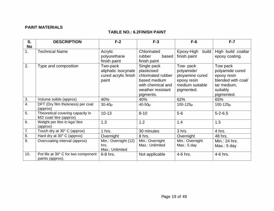
Page 19 of 49
PAINT MATERIALSTABLE NO.: 6.2FINISH PAINT
S.No
DESCRIPTION F-2 F-3 F-6 F-7
1. Technical Name Acrylicpolyurethanefinish paint
Chlorinatedrubber basedfinish paint
Epoxy-High buildfinish paint
High build coaltarepoxy coating.
2. Type and composition Two-packaliphatic isocynatecured acrylic finishpaint
Single packplasticisedchlorinated rubberbased mediumwith chemical andweather resistantpigments.
Tow- packpolyamide/ployamine curedepoxy resinmedium suitablepigmented.
Tow packpolyamide curedepoxy resinblended with coal/tar medium,suitablypigmented.
3. Volume solids (approx) 40% 40% 62% 65%4. DFT (Dry film thickness) per coat
(approx)30-40µ 40-50µ 100-125µ 100-125µ
5. Theoretical covering capacity inM2/ coat/ litre (approx)
10-13 8-10 5-6 5-2-6.5
6. Welght per litre in kgs/ litre(approx)
1.3 1.2 1.4 1.5
7. Touch dry at 30° C (approx) 1 hrs. 30 minutes 3 hrs. 4 hrs.8. Hard dry at 30° C (approx) Overnight 8 hrs. Overnight 48 hrs.9. Overcoating interval (approx) Min.: Overnight (12)
hrs.Max.: Unlimited
Min.: OvernightMax.: Unlimited
Min.: OvernightMax.: 5 day
Min.: 24 hrs.Max.: 5 day
10. Pot life at 30° C for two componentpaints (approx).
6-8 hrs. Not applicable 4-6 hrs. 4-6 hrs.
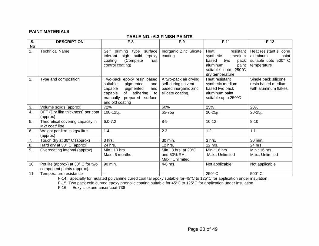
Page 20 of 49
PAINT MATERIALSTABLE NO.: 6.3 FINISH PAINTS
S.No
DESCRIPTION F-8 F-9 F-11 F-12
1. Technical Name Self priming type surfacetolerant high build epoxycoating (Complete rustcontrol coating)
Inorganic Zinc Slicatecoating
Heat resistantsynthetic mediumbased two packaluminum paintsuitable upto 250°Cdry temperature
Heat resistant siliconealuminum paintsuitable upto 500° Ctemperature
2. Type and composition Two-pack epoxy resin basedsuitable pigmented andcapable pigmented andcapable of adhering tomanually prepared surfaceand old coating
A two-pack air dryingself-curing solventbased inorganic zincsilicate coating.
Heat resistantsynthetic mediumbased two packaluminum paintsuitable upto 250°C
Single pack siliconeresin based mediumwith aluminum flakes.
3. Volume solids (approx) 72% 60% 25% 20%4. DFT (Dry film thickness) per coat
(approx)100-125µ 65-75µ 20-25µ 20-25µ
5. Theoretical covering capacity inM2/ coat/ litre
6.0-7.2 8-9 10-12 8-10
6. Welght per litre in kgs/ litre(approx)
1.4 2.3 1.2 1.1
7. Touch dry at 30° C (approx) 3 hrs. 30 min. 3 hrs. 30 min.8. Hard dry at 30° C (approx) 24 hrs. 12 hrs. 12 hrs. 24 hrs.9. Overcoating interval (approx) Min.: 10 hrs.
Max.: 6 monthsMin.: 8 hrs. at 20°Cand 50% RH.Max.: Unlimited
Min.: 16 hrs. Max.: Unlimited
Min.: 16 hrs.Max.: Unlimited
10. Pot life (approx) at 30° C for twocomponent paints (approx).
90 min. 4-6 hrs. Not applicable Not applicable
11. Temperature resistance - - 250° C 500° CF-14: Specially for mulated polyamine cured coal tal epoxy suitable for-45°C to 125°C for application under insulationF-15: Two pack cold curved epoxy phenolic coating suitable for 45°C to 125°C for application under insulationF-16: Eoxy siloxane anser coat 738
Page 21 of 49
Notes:
1. Covering capacity and DFT depends on method of application. Coveringcapacity specified above are theoretical. Allowing the loose during theapplication, minimum specified DFT should be maintained.
2. All primers and finish coats should be cold cured and air drying unlessotherwise specified.
3. All paints shall be applied in accordance with manufacturer’s instructionfor surface preparation, intervals, curing and application. The surfacepreparation, quality and workmanship should be ensured.
4. Technical data sheets for all paints shall be supplied at the time ofsubmission of quotations.
6.4 List of recommended manufacturers
The paint shall conform to the specifications given above and the bestquality in their products range of the manufacturers listed in Annexure-I.
7.0 PAINT SYSTEM
The paint system should vary with type of environment envisaged in andaround the plants. Three types of environment as given below areconsidered for selection of paint system. The paint system is also given forspecific requirements.
Primers & finish coats covered in table nos. 7.0 to 15.0
PRIMERS
P-2 : Chlorinated Rubber Zinc Phosphate Primer
P-4 : Etch Primer/ Wash Primer
P-6 : Epoxy Zic Phosphate Primer
FINISH COATS/ PAINTS
F-2 : Acrylic- Polyurethane finish paint
F-3 : Chlorinated Rubber Finish Paint
F-6 : High Build Epoxy finish coating
Page 22 of 49
F-7 : High Build Coal Tar epoxy coating
F-8 : Self-priming surface tolerant high build epoxycoating
F-9 : Inorganic Zinc Silicate Coating.
F-11 : Heat resistant Synthetic medium based Aluminum paint.
F-12 : Heat resistant Silicone Aluminum paint.
F-14 : Specially formulated polyamine-cured coal forEpoxy coating
F-15 : Epoxy phenolic coating
F-16 : Epoxy Siloxane Coating : Amercoat 738
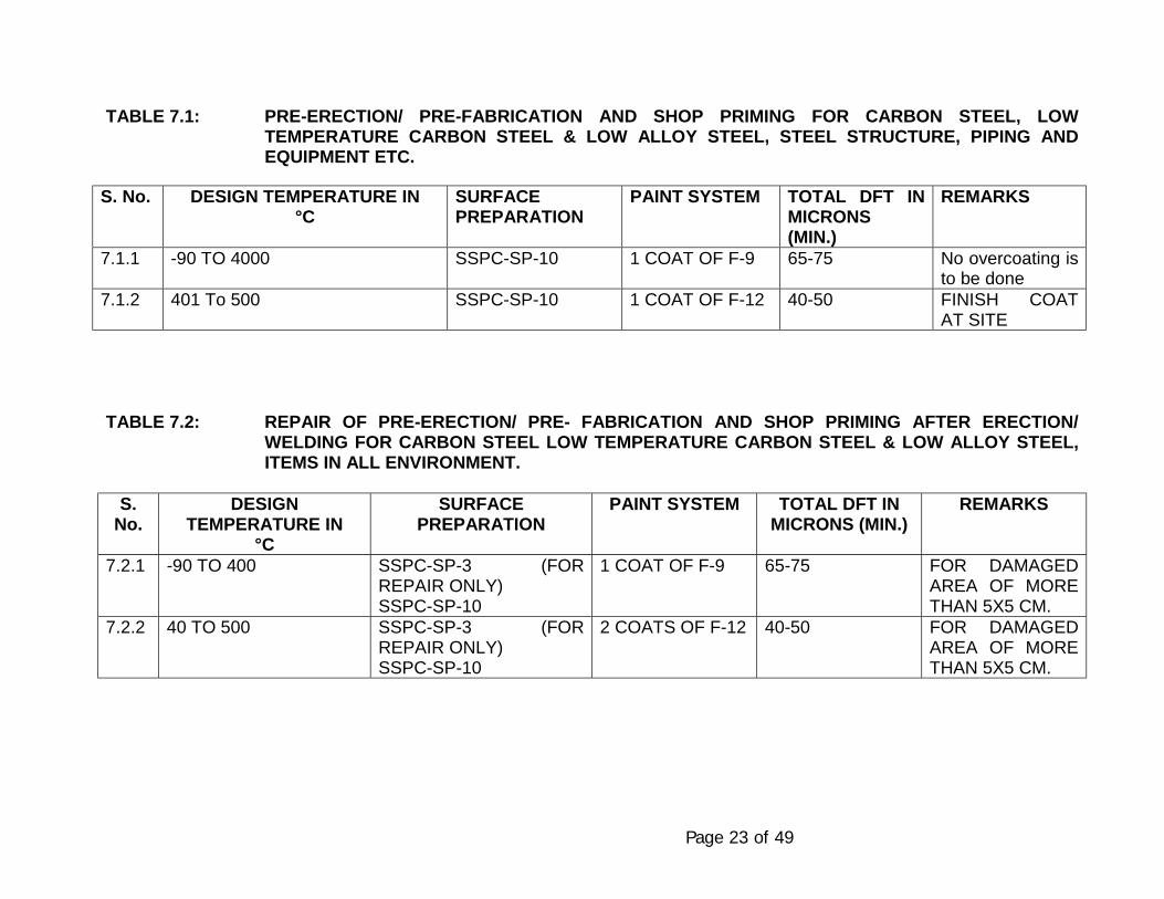
Page 23 of 49
TABLE 7.1: PRE-ERECTION/ PRE-FABRICATION AND SHOP PRIMING FOR CARBON STEEL, LOWTEMPERATURE CARBON STEEL & LOW ALLOY STEEL, STEEL STRUCTURE, PIPING ANDEQUIPMENT ETC.
S. No. DESIGN TEMPERATURE IN°C
SURFACEPREPARATION
PAINT SYSTEM TOTAL DFT INMICRONS(MIN.)
REMARKS
7.1.1 -90 TO 4000 SSPC-SP-10 1 COAT OF F-9 65-75 No overcoating isto be done
7.1.2 401 To 500 SSPC-SP-10 1 COAT OF F-12 40-50 FINISH COATAT SITE
TABLE 7.2: REPAIR OF PRE-ERECTION/ PRE- FABRICATION AND SHOP PRIMING AFTER ERECTION/WELDING FOR CARBON STEEL LOW TEMPERATURE CARBON STEEL & LOW ALLOY STEEL,ITEMS IN ALL ENVIRONMENT.
S.No.
DESIGNTEMPERATURE IN
°C
SURFACEPREPARATION
PAINT SYSTEM TOTAL DFT INMICRONS (MIN.)
REMARKS
7.2.1 -90 TO 400 SSPC-SP-3 (FORREPAIR ONLY)SSPC-SP-10
1 COAT OF F-9 65-75 FOR DAMAGEDAREA OF MORETHAN 5X5 CM.
7.2.2 40 TO 500 SSPC-SP-3 (FORREPAIR ONLY)SSPC-SP-10
2 COATS OF F-12 40-50 FOR DAMAGEDAREA OF MORETHAN 5X5 CM.
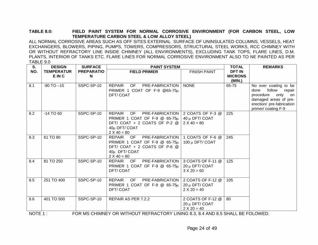
Page 24 of 49
TABLE 8.0: FIELD PAINT SYSTEM FOR NORMAL CORROSIVE ENVIRONMENT (FOR CARBON STEEL, LOWTEMPERATURE CARBON STEEL & LOW ALLOY STEEL)
ALL NORMAL CORROSIVE AREAS SUCH AS OFF SITES EXTERNAL SURFACE OF UNINSULATED COLUMNS, VESSELS, HEATEXCHANGERS, BLOWERS, PIPING, PUMPS, TOWERS, COMPRESSORS, STRUCTURAL STEEL WORKS, RCC CHIMNEY WITHOR WITHOUT REFRACTORY LINE INSIDE CHIMNEY (ALL ENVIRONMENTS), EXCLUDING TANK TOPS, FLARE LINES, D.M.PLANTS, INTERIOR OF TANKS ETC. FLARE LINES FOR NORMAL CORROSIVE ENVIRONMENT ALSO TO NE PAINTED AS PERTABLE 9.0
PAINT SYSTEMS.NO.
DESIGNTEMPERATUR
E IN C
SURFACEPREPARATIO
NFIELD PRIMER FINISH PAINT
TOTALDFT IN
MICRONS(MIN.)
REMARKS
8.1 -90 TO –15 SSPC-SP-10 REPAIR OF PRE-FABRICATIONPRIMER 1 COAT OF F-9 @65-75µDFT/ COAT
NONE 65-75 No over coating to bedone follow repairprocedure only ondamaged areas of pre-erection/ pre-fabricationprimer/ coating F-9
8.2 -14 TO 60 SSPC-SP-10 REPAIR OF PRE-FABRICATIONPRIMER 1 COAT OF F-9 @ 65-75µDFT/ COAT + 2 COATS OF P-2 @40µ DFT/ COAT2 X 40 = 80
2 COATS OF F-3 @40 µ DFT/ COAT2 X 40 = 80
225
8.3 61 TO 80 SSPC-SP-10 REPAIR OF PRE-FABRICATIONPRIMER 1 COAT OF F-9 @ 65-75µDFT/ COAT + 2 COATS OF P-6 @40µ DFT/ COAT2 X 40 = 80
1 COATS OF F-6 @100 µ DFT/ COAT
245
8.4 81 TO 250 SSPC-SP-10 REPAIR OF PRE-FABRICATIONPRIMER 1 COAT OF F-9 @ 65-75µDFT/ COAT
3 COATS OF F-11 @20 µ DFT/ COAT3 X 20 = 60
125
8.5 251 TO 400 SSPC-SP-10 REPAIR OF PRE-FABRICATIONPRIMER 1 COAT OF F-9 @ 65-75µDFT/ COAT
2 COATS OF F-12 @20 µ DFT/ COAT2 X 20 = 40
105
8.6 401 TO 500 SSPC-SP-10 REPAIR AS PER 7.2.2 2 COATS OF F-12 @20 µ DFT/ COAT2 X 20 = 40
80
NOTE 1 : FOR MS CHIMNEY OR WITHOUT REFRACTORY LINING 8.3, 8.4 AND 8.5 SHALL BE FOLOWED.
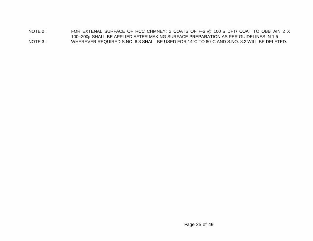
Page 25 of 49
NOTE 2 : FOR EXTENAL SURFACE OF RCC CHMNEY: 2 COATS OF F-6 @ 100 µ DFT/ COAT TO OBBTAIN 2 X100=200µ SHALL BE APPLIED AFTER MAKING SURFACE PREPARATION AS PER GUIDELINES IN 1.5
NOTE 3 : WHEREVER REQUIRED S.NO. 8.3 SHALL BE USED FOR 14°C TO 80°C AND S.NO. 8.2 WILL BE DELETED.
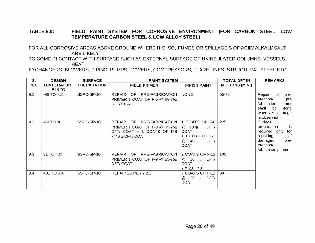
Page 26 of 49
TABLE 9.0: FIELD PAINT SYSTEM FOR CORROSIVE ENVIRONMENT (FOR CARBON STEEL, LOWTEMPERATURE CARBON STEEL & LOW ALLOY STEEL)
FOR ALL CORROSIVE AREAS ABOVE GROUND WHERE H2S, SO2 FUMES OR SPILLAGE’S OF ACID/ ALKALI/ SALTARE LIKELY
TO COME IN CONTACT WITH SURFACE SUCH AS EXTERNAL SURFACE OF UNINSULATED COLUMNS, VESSELS,HEAT
EXCHANGERS, BLOWERS, PIPING, PUMPS, TOWERS, COMPRESSORS, FLARE LINES, STRUCTURAL STEEL ETC.
PAINT SYSTEMS.NO.
DESIGNTEMPERATUR
E IN °C
SURFACEPREPARATION FIELD PRIMER FINISH PAINT
TOTAL DFT INMICRONS (MIN.)
REMARKS
9.1 -90 TO –15 SSPC-SP-10 REPAIR OF PRE-FABRICATIONPRIMER 1 COAT OF F-9 @ 65-75µDFT/ COAT
NONE 65-75 Repair of pre-erection/ prefabrication primershall be donewherever damageis observed.
9.2 -14 TO 80 SSPC-SP-10 REPAIR OF PRE-FABRICATIONPRIMER 1 COAT OF F-9 @ 65-75µDFT/ COAT + 1 COATS OF P-6@40 µ DFT/ COAT
1 COATS OF F-6@ 100µ DFT/COAT+ 1 COAT OF F-2@ 40µ DFT/COAT
225 Surfacepreparation isrequired only forrepairing ofdamaged pre-erection/fabrication primer
9.3 81 TO 400 SSPC-SP-10 REPAIR OF PRE-FABRICATIONPRIMER 1 COAT OF F-9 @ 65-75µDFT/ COAT
2 COATS OF F-12@ 20 µ DFT/COAT2 X 20 = 40
105
9.4 401 TO 500 SSPC-SP-10 REPAIR 2S PER 7.2.2 2 COATS OF F-12@ 20 µ DFT/COAT
80
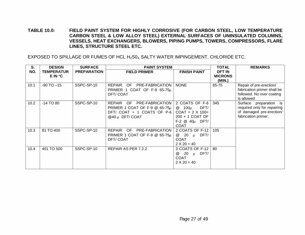
Page 27 of 49
TABLE 10.0: FIELD PAINT SYSTEM FOR HIGHLY CORROSIVE (FOR CARBON STEEL, LOW TEMPERATURECARBON STEEL & LOW ALLOY STEEL) EXTERNAL SURFACES OF UNINSULATED COLUMNS,VESSELS, HEAT EXCHANGERS, BLOWERS, PIPING PUMPS, TOWERS, COMPRESSORS, FLARELINES, STRUCTURE STEEL ETC.
EXPOSED TO SPILLAGE OR FUMES OF HCL H2S04, SALTY WATER IMPINGEMENT, CHLORIDE ETC.
PAINT SYSTEMS.NO.
DESIGNTEMPERATUR
E IN °C
SURFACEPREPARATION FIELD PRIMER FINISH PAINT
TOTALDFT IN
MICRONS(MIN.)
REMARKS
10.1 -90 TO –15 SSPC-SP-10 REPAIR OF PRE-FABRICATIONPRIMER 1 COAT OF F-9 65-75µDFT/ COAT
NONE 65-75 Repair of pre-erection/fabrication primer shall befollowed. No over coatingis allowed
10.2 -14 TO 80 SSPC-SP-10 REPAIR OF PRE-FABRICATIONPRIMER 1 COAT OF F-9 @ 65-75µDFT/ COAT + 1 COATS OF P-6@40 µ DFT/ COAT
2 COATS OF F-6@ 100µ DFT/COAT = 2 X 100=200 + 1 COAT OFF-2 @ 40µ DFT/COAT
345 Surface preparation isrequired only for repairingof damaged pre-erection/fabrication primer.
10.3 81 TO 400 SSPC-SP-10 REPAIR OF PRE-FABRICATIONPRIMER 1 COAT OF F-9 @ 65-75µDFT/ COAT
2 COATS OF F-12@ 20 µ DFT/COAT2 X 20 = 40
105
10.4 401 TO 500 SSPC-SP-10 REPAIR AS PER 7.2.2 3 COATS OF F-12@ 20 µ DFT/COAT2 X 20 = 40
80
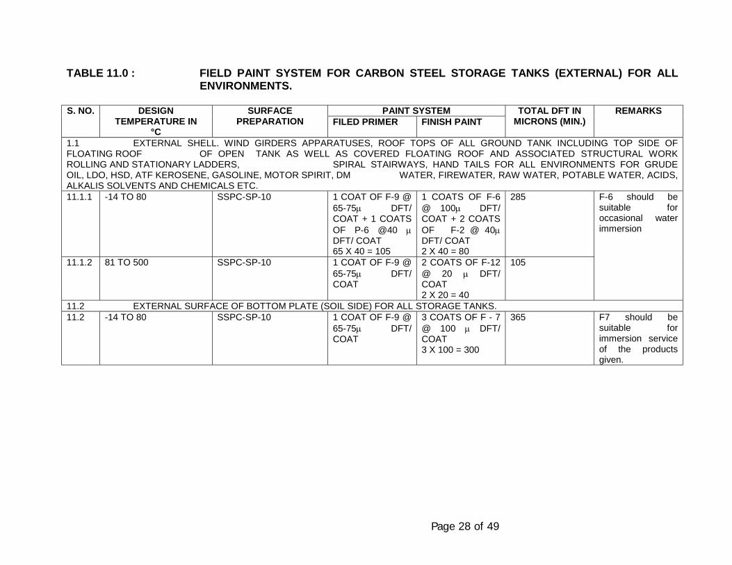
Page 28 of 49
TABLE 11.0 : FIELD PAINT SYSTEM FOR CARBON STEEL STORAGE TANKS (EXTERNAL) FOR ALLENVIRONMENTS.
PAINT SYSTEMS. NO. DESIGNTEMPERATURE IN
°C
SURFACEPREPARATION FILED PRIMER FINISH PAINT
TOTAL DFT INMICRONS (MIN.)
REMARKS
1.1 EXTERNAL SHELL. WIND GIRDERS APPARATUSES, ROOF TOPS OF ALL GROUND TANK INCLUDING TOP SIDE OFFLOATING ROOF OF OPEN TANK AS WELL AS COVERED FLOATING ROOF AND ASSOCIATED STRUCTURAL WORKROLLING AND STATIONARY LADDERS, SPIRAL STAIRWAYS, HAND TAILS FOR ALL ENVIRONMENTS FOR GRUDEOIL, LDO, HSD, ATF KEROSENE, GASOLINE, MOTOR SPIRIT, DM WATER, FIREWATER, RAW WATER, POTABLE WATER, ACIDS,ALKALIS SOLVENTS AND CHEMICALS ETC.11.1.1 -14 TO 80 SSPC-SP-10 1 COAT OF F-9 @
65-75µ DFT/COAT + 1 COATSOF P-6 @40 µDFT/ COAT65 X 40 = 105
1 COATS OF F-6@ 100µ DFT/COAT + 2 COATSOF F-2 @ 40µDFT/ COAT2 X 40 = 80
285
11.1.2 81 TO 500 SSPC-SP-10 1 COAT OF F-9 @65-75µ DFT/COAT
2 COATS OF F-12@ 20 µ DFT/COAT2 X 20 = 40
105
F-6 should besuitable foroccasional waterimmersion
11.2 EXTERNAL SURFACE OF BOTTOM PLATE (SOIL SIDE) FOR ALL STORAGE TANKS.11.2 -14 TO 80 SSPC-SP-10 1 COAT OF F-9 @
65-75µ DFT/COAT
3 COATS OF F - 7@ 100 µ DFT/COAT3 X 100 = 300
365 F7 should besuitable forimmersion serviceof the productsgiven.

Page 29 of 49
TABLE 12.0 : FIELD PAINT SYSTEM FOR CARBON STEEL AND ALLOY STORAGE TANK: (INTERNAL)PAINT SYSTEMS. NO. DESIGN TEMPERATURE IN
°CSURFACE PREPARATION
FILED PRIMER FINISH PAINTTOTAL DFT IN
MICRONS (MIN.)REMARKS
INTERNAL SURFACE OF UNDERSIDE OF FLOATING ROOF, INTERNAL STRUCTURAL OF CONE ROOF, BOTTOM PLATE, ROOF STRUCTURE,STEEL, LADDERS SUPPORTS FOR STORING GRUIDE OIL, LDO AND HSD (EXCLUDING WHITE OIL PRODUCTS)
12.1 -14 TO 80 SSPC-SP-10 1 COAT OF F-9 @ 65-75µ DFT/ COAT
3 COATS OF F-7 @ 100µDFT/ COAT3 X 100 = 300
365 F7 should be suitable forimmersion service of theproducts given.
12.2 BARE SHEEL OF INSIDE FLOATING ROOF TANK AND CONE ROOF TANK FOR PRODUCTS MENTIONED IN 12.112.2.1 -14 TO 80 SSPC-SP-10 PHOSPHATING
TREATMENT WITHPHOSPHATINGCHEMICALS (2COATS)
2 COATS OF @10 µ2 X 10 = 20
20
12.3 FLOATING CONE ROOF TANKS FOR PETROLEUM PRODUCTS SUCH AS ATF, GASOLINE, NAPHTHA, KEROSENE, MOTOR SPIRIT, INSIDEOF BOTTOM PLATE, UNDERSIDE OF FLOATING ROOF AND SHELL ABOVE MAXIMUM LIQUID LEVEL AND STRUCTURAL STEEL , LADDERS ETC.12.3.1 -14 TO 80 SSPC-SP-10 1 COAT OF F-9 @ 65-
75µ DFT/ COAT3 COATS OF F-6 @ 100µDFT/ COAT3 X 100 = 300
365 F-6 should be suitable forimmersion service ofpetroleum produce likeATF, Kerosene, petrol etc.
12.4 BARE SHELL OF INSIDE OF FLOATING CONE ROOF TANKS FOR PRODUCTS MENTIONED IN 12.312.4.1 -14 TO 80 SSPC-SP-10 1 COAT OF F-9 @ 65-
75µ DFT/ COATNONE 65-75 No over coating is allowed
same as per pre-erectionprimer, if any
12.5 INTERNAL PROTECTION IF FIXED ROOF TYPE STORAGE TANKS FOR POTABLE WATER: INSIDE OF SHELL, UNDER SIDE OF ROOF AND ROOF STRUCTUREINSIDE SURFACE BOTTOM PLATE AND STRURAL STEEL WORKS, LADDERS, WALKWAYS, PLATFORMS ETC.12.5.1 -14 TO 80 SSPC-SP-10 2 COAT OF F-6 @ 40µ
DFT/ COAT2 X 40 = 80
2 COATS OF F-6 @ 100µDFT/ COAT2 X 100 = 200
280 F-6 shall be suitable forimmersion service.
12.6 D. M. (DEMINERALISED WATER) AND HYDROCHLORIC ACID (HCL): INTERNAL SHELL, BOTTOM PLATE AND ALL ACCESSORIES12.6.1 -14 TO 80 SSPC-SP-10 EBONITE RUBBER LINING AS PER SMMS SPECIFICATION 6-06-20412.7 EG TANKS (INTERNAL SHELL, BOTTOM PLATE ROOF AND ALL ACCESSORIES)12.7.1 ALL SSPC-SP-10 3 COATS VINYL CHLORIDE CO-POLYMER
AMERCOAT 23 @ 75µ / COAT225
12.8 INSIDE PONTOON AND INSIDE OF DOUBLE DECK OF ALL FLOATING ROOFS.12.8.1 -14 TO 80 SSPC-SP-3 1 COAT OF F-8 @
100µ DFT/ COAT1 COATS OF F-6 @ 100µDFT/ COAT1 X 100 = 100
200
12.9 INTERNAL SURFACE OF AMINE & SOUR WATER STORAGE TANKS12.9.1 -14 TO 80 SSPC-SP-10 1 COAT OF F-9 @ 65-
75µ DFT/ COAT2 X 40 = 80
2 COATS OF F-15 @ 75µDFT/ COAT2 X 75 = 150
215-225
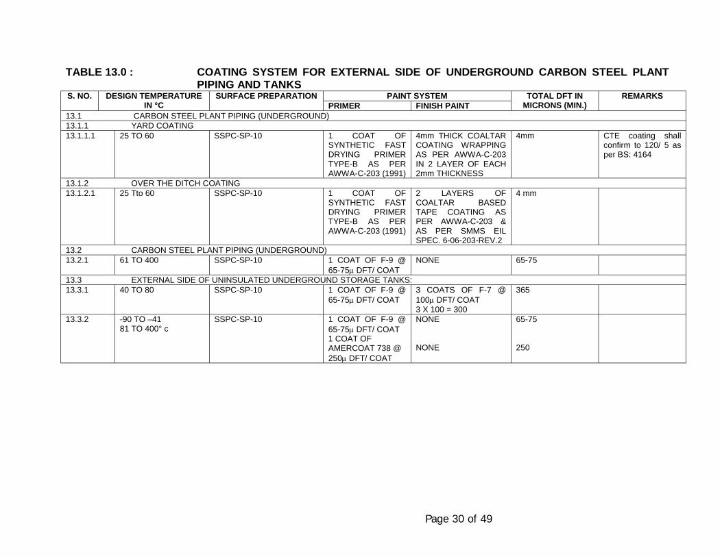
Page 30 of 49
TABLE 13.0 : COATING SYSTEM FOR EXTERNAL SIDE OF UNDERGROUND CARBON STEEL PLANTPIPING AND TANKS
PAINT SYSTEMS. NO. DESIGN TEMPERATUREIN °C
SURFACE PREPARATIONPRIMER FINISH PAINT
TOTAL DFT INMICRONS (MIN.)
REMARKS
13.1 CARBON STEEL PLANT PIPING (UNDERGROUND)13.1.1 YARD COATING13.1.1.1 25 TO 60 SSPC-SP-10 1 COAT OF
SYNTHETIC FASTDRYING PRIMERTYPE-B AS PERAWWA-C-203 (1991)
4mm THICK COALTARCOATING WRAPPINGAS PER AWWA-C-203IN 2 LAYER OF EACH2mm THICKNESS
4mm CTE coating shallconfirm to 120/ 5 asper BS: 4164
13.1.2 OVER THE DITCH COATING13.1.2.1 25 Tto 60 SSPC-SP-10 1 COAT OF
SYNTHETIC FASTDRYING PRIMERTYPE-B AS PERAWWA-C-203 (1991)
2 LAYERS OFCOALTAR BASEDTAPE COATING ASPER AWWA-C-203 &AS PER SMMS EILSPEC. 6-06-203-REV.2
4 mm
13.2 CARBON STEEL PLANT PIPING (UNDERGROUND)13.2.1 61 TO 400 SSPC-SP-10 1 COAT OF F-9 @
65-75µ DFT/ COATNONE 65-75
13.3 EXTERNAL SIDE OF UNINSULATED UNDERGROUND STORAGE TANKS:13.3.1 40 TO 80 SSPC-SP-10 1 COAT OF F-9 @
65-75µ DFT/ COAT3 COATS OF F-7 @100µ DFT/ COAT3 X 100 = 300
365
13.3.2 -90 TO –4181 TO 400° c
SSPC-SP-10 1 COAT OF F-9 @65-75µ DFT/ COAT1 COAT OFAMERCOAT 738 @250µ DFT/ COAT
NONE
NONE
65-75
250
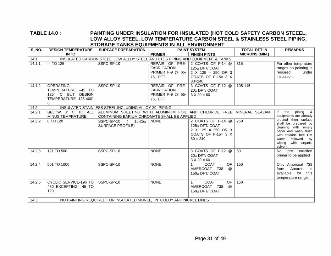
Page 31 of 49
TABLE 14.0 : PAINTING UNDER INSULATION FOR INSULATED (HOT COLD SAFETY CARBON STEEEL,LOW ALLOY STEEL, LOW TEMPERATURE CARBON STEEL & STAINLESS STEEL PIPING,STORAGE TANKS EQUIPMENTS IN ALL ENVIRONMENT
PAINT SYSTEMS. NO. DESIGN TEMPERATUREIN °C
SURFACE PREPARATIONPRIMER FINISH PINTS
TOTAL DFT INMICRONS (MIN.)
REMARKS
14.1 INSULATED CARBON STEEL, LOW ALLOY STEEL AND LTCS PIPING AND EQUIPMENT & TANKS14.1.1 -4 TO 125 SSPC-SP-10 REPAIR OF PRE-
FABRICATIONPRIMER F-9 @ 65-75µ DFT
2 COATS OF F-14 @125µ DFT/ COAT2 X 125 = 250 OR 3COATS OF F-15= 3 X80=240
315 For other tempratureranges no painting isrequired underinsulation.
14.1.2 OPERATINGTEMPERATURE –45 TO125° C BUT DESIGNTEMPERATURE 126-400°C
SSPC-SP-10 REPAIR OF PRE-FABRICATIONPRIMER F-9 @ 65-75µ DFT
3 COATS OF F-12 @20µ DFT/ COAT3 X 20 = 60
105-115
14.2 INSULATED STAINLESS STEEL INCLUDING ALLOY-20- PIPING14.2.1 BELOW 0° C TO ALL
MINUS TEMPRATUREALUMINUM SHEETING WITH ALUMINUM FOIL AND CHLORIDE FREE MINERAL SEALANTCONTAINING BARIUM CHROMATE SHALL BE APPLIED
14.2.2 0 TO 120 SSPC-SP-10 ( 15-25µSURFACE PROFILE)
NONE 2 COATS OF F-14 @125µ DFT/ COAT2 X 125 = 250 OR 3COATS OF F-15= 3 X80 = 240
250
If the piping &equipments are alreadyerected then surfaceshall be prepared bycleaning with emerypaper and wash/ flushwith chloride free DMwater followed bywiping with organicsolvent
14.2.3 121 TO 500 SSPC-SP-10 NONE 3 COATS OF F-12 @20µ DFT/ COAT3 X 20 = 60
60 No pre erectionprimer to be applied
14.2.4 501 TO 1000 SSPC-SP-10 NONE 1 COAT OFAMERCOAT 738 @150µ DFT/ COAT
150 Only Amorcoat 738from Amoron isavailable for thistemperature range.
14.2.5 CYCLIC SERVICE-196 TO480 EXCEPTING –45 TO120
SSPC-SP-10 NONE 1 COAT OFAMERCOAT 738 @150µ DFT/ COAT
150
14.3 NO PAINTING REQUIRED FOR INSULATED MONEL, IN COLOY AND NICKEL LINES

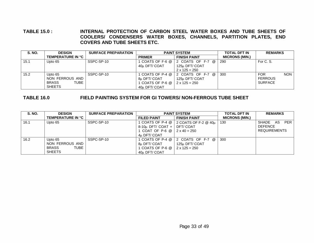
Page 33 of 49
TABLE 15.0 : INTERNAL PROTECTION OF CARBON STEEL WATER BOXES AND TUBE SHEETS OFCOOLERS/ CONDENSERS WATER BOXES, CHANNELS, PARTITION PLATES, ENDCOVERS AND TUBE SHEETS ETC.
PAINT SYSTEMS. NO. DESIGNTEMPERATURE IN °C
SURFACE PREPARATIONPRIMER FINISH PAINT
TOTAL DFT INMICRONS (MIN.)
REMARKS
15.1 Upto 65 SSPC-SP-10 1 COATS OF F-6 @40µ DFT/ COAT
2 COATS OF F-7 @125µ DFT/ COAT2 x 125 = 250
290 For C. S.
15.2 Upto 65NON FERROUS ANDBRASS TUBESHEETS
SSPC-SP-10 1 COATS OF P-4 @8µ DFT/ COAT1 COATS OF P-6 @40µ DFT/ COAT
2 COATS OF F-7 @125µ DFT/ COAT2 x 125 = 250
300 FOR NONFERROUSSURFACE
TABLE 16.0 FIELD PAINTING SYSTEM FOR GI TOWERS/ NON-FERROUS TUBE SHEET
PAINT SYSTEMS. NO. DESIGNTEMPERATURE IN °C
SURFACE PREPARATIONFILED PAINT FINISH PAINT
TOTAL DFT INMICRONS (MIN.)
REMARKS
16.1 Upto 65 SSPC-SP-10 1 COATS OF P-4 @8-10µ DFT/ COAT +1 COAT OF P-6 @4µ DFT/ COAT
2 COATS OF F-2 @ 40µDFT/ COAT2 x 40 = 250
130 SHADE AS PERDEFENCEREQUIREMENTS
16.2 Upto 65NON FERROUS ANDBRASS TUBESHEETS
SSPC-SP-10 1 COATS OF P-4 @8µ DFT/ COAT1 COATS OF P-6 @40µ DFT/ COAT
2 COATS OF F-7 @125µ DFT/ COAT2 x 125 = 250
300
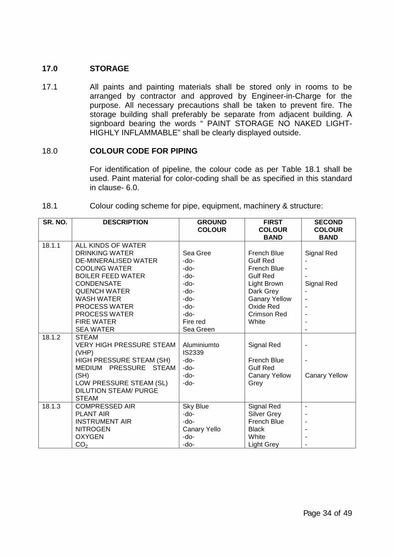
Page 34 of 49
17.0 STORAGE
17.1 All paints and painting materials shall be stored only in rooms to bearranged by contractor and approved by Engineer-in-Charge for thepurpose. All necessary precautions shall be taken to prevent fire. Thestorage building shall preferably be separate from adjacent building. Asignboard bearing the words “ PAINT STORAGE NO NAKED LIGHT-HIGHLY INFLAMMABLE” shall be clearly displayed outside.
18.0 COLOUR CODE FOR PIPING
For identification of pipeline, the colour code as per Table 18.1 shall beused. Paint material for color-coding shall be as specified in this standardin clause- 6.0.
18.1 Colour coding scheme for pipe, equipment, machinery & structure:
SR. NO. DESCRIPTION GROUNDCOLOUR
FIRSTCOLOUR
BAND
SECONDCOLOUR
BAND18.1.1 ALL KINDS OF WATER
DRINKING WATERDE-MINERALISED WATERCOOLING WATERBOILER FEED WATERCONDENSATEQUENCH WATERWASH WATERPROCESS WATERPROCESS WATERFIRE WATERSEA WATER
Sea Gree-do--do--do--do--do--do--do--do-Fire redSea Green
French BlueGulf RedFrench BlueGulf RedLight BrownDark GreyGanary YellowOxide RedCrimson RedWhite
Signal Red---Signal Red------
18.1.2 STEAMVERY HIGH PRESSURE STEAM(VHP)HIGH PRESSURE STEAM (SH)MEDIUM PRESSURE STEAM(SH)LOW PRESSURE STEAM (SL)DILUTION STEAM/ PURGESTEAM
AluminiumtoIS2339-do--do--do--do-
Signal Red
French BlueGulf RedCanary YellowGrey
-
-
Canary Yellow
18.1.3 COMPRESSED AIRPLANT AIRINSTRUMENT AIRNITROGENOXYGENCO2
Sky Blue-do--do-Canary Yello-do--do-
Signal RedSilver GreyFrench BlueBlackWhiteLight Grey
------
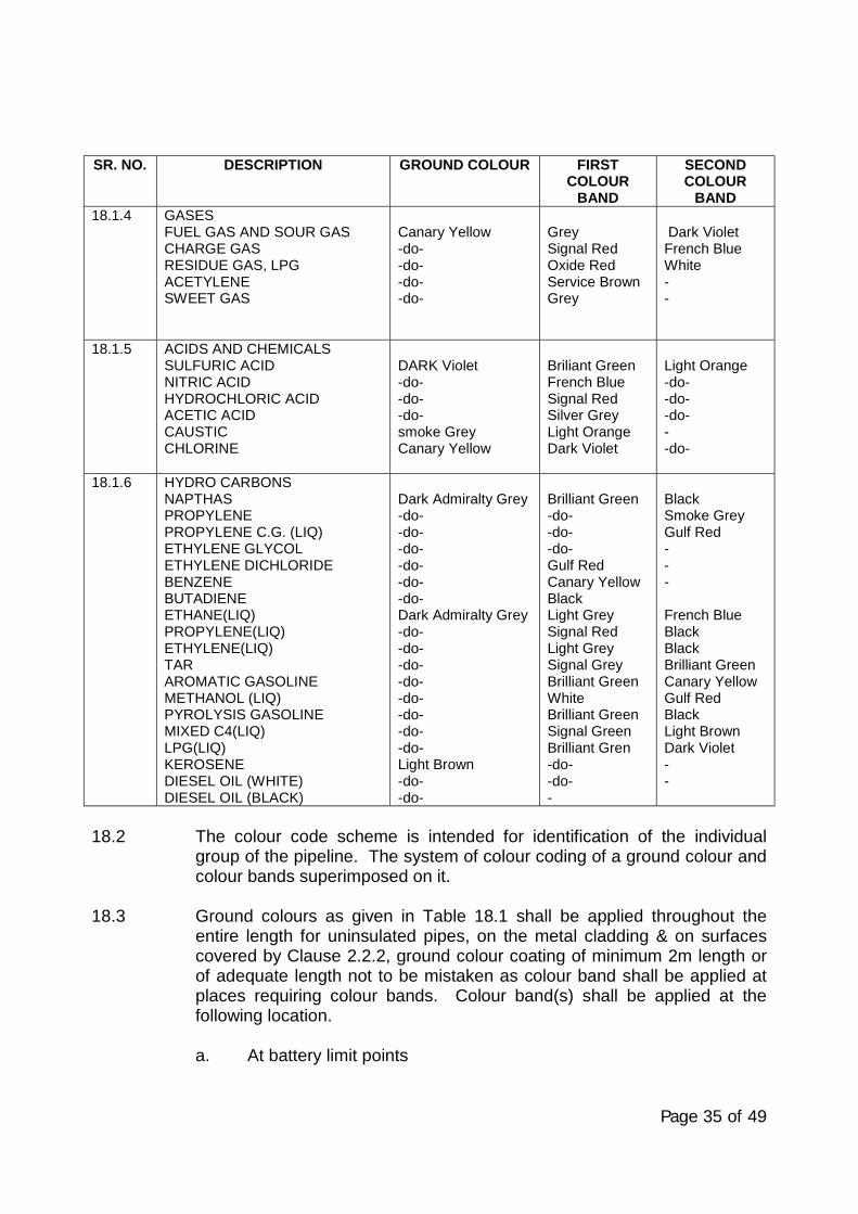
Page 35 of 49
SR. NO. DESCRIPTION GROUND COLOUR FIRSTCOLOUR
BAND
SECONDCOLOUR
BAND18.1.4 GASES
FUEL GAS AND SOUR GASCHARGE GASRESIDUE GAS, LPGACETYLENESWEET GAS
Canary Yellow-do--do--do--do-
GreySignal RedOxide RedService BrownGrey
Dark VioletFrench BlueWhite--
18.1.5 ACIDS AND CHEMICALSSULFURIC ACIDNITRIC ACIDHYDROCHLORIC ACIDACETIC ACIDCAUSTICCHLORINE
DARK Violet-do--do--do-smoke GreyCanary Yellow
Briliant GreenFrench BlueSignal RedSilver GreyLight OrangeDark Violet
Light Orange-do--do--do---do-
18.1.6 HYDRO CARBONSNAPTHASPROPYLENEPROPYLENE C.G. (LIQ)ETHYLENE GLYCOLETHYLENE DICHLORIDEBENZENEBUTADIENEETHANE(LIQ)PROPYLENE(LIQ)ETHYLENE(LIQ)TARAROMATIC GASOLINEMETHANOL (LIQ)PYROLYSIS GASOLINEMIXED C4(LIQ)LPG(LIQ)KEROSENEDIESEL OIL (WHITE)DIESEL OIL (BLACK)
Dark Admiralty Grey-do--do--do--do--do--do-Dark Admiralty Grey-do--do--do--do--do--do--do--do-Light Brown-do--do-
Brilliant Green-do--do--do-Gulf RedCanary YellowBlackLight GreySignal RedLight GreySignal GreyBrilliant GreenWhiteBrilliant GreenSignal GreenBrilliant Gren-do--do--
BlackSmoke GreyGulf Red---
French BlueBlackBlackBrilliant GreenCanary YellowGulf RedBlackLight BrownDark Violet--
18.2 The colour code scheme is intended for identification of the individualgroup of the pipeline. The system of colour coding of a ground colour andcolour bands superimposed on it.
18.3 Ground colours as given in Table 18.1 shall be applied throughout theentire length for uninsulated pipes, on the metal cladding & on surfacescovered by Clause 2.2.2, ground colour coating of minimum 2m length orof adequate length not to be mistaken as colour band shall be applied atplaces requiring colour bands. Colour band(s) shall be applied at thefollowing location.
a. At battery limit points
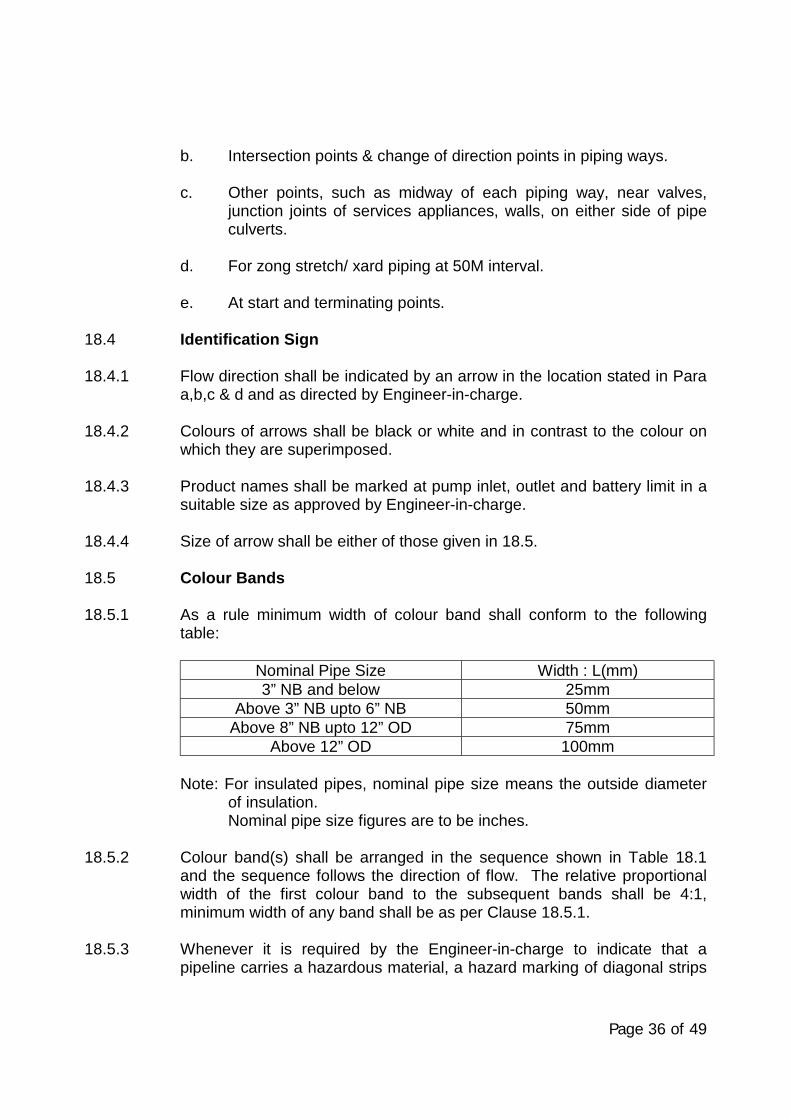
Page 36 of 49
b. Intersection points & change of direction points in piping ways.
c. Other points, such as midway of each piping way, near valves,junction joints of services appliances, walls, on either side of pipeculverts.
d. For zong stretch/ xard piping at 50M interval.
e. At start and terminating points.
18.4 Identification Sign
18.4.1 Flow direction shall be indicated by an arrow in the location stated in Paraa,b,c & d and as directed by Engineer-in-charge.
18.4.2 Colours of arrows shall be black or white and in contrast to the colour onwhich they are superimposed.
18.4.3 Product names shall be marked at pump inlet, outlet and battery limit in asuitable size as approved by Engineer-in-charge.
18.4.4 Size of arrow shall be either of those given in 18.5.
18.5 Colour Bands
18.5.1 As a rule minimum width of colour band shall conform to the followingtable:
Nominal Pipe Size Width : L(mm)3” NB and below 25mm
Above 3” NB upto 6” NB 50mmAbove 8” NB upto 12” OD 75mm
Above 12” OD 100mm
Note: For insulated pipes, nominal pipe size means the outside diameterof insulation.Nominal pipe size figures are to be inches.
18.5.2 Colour band(s) shall be arranged in the sequence shown in Table 18.1and the sequence follows the direction of flow. The relative proportionalwidth of the first colour band to the subsequent bands shall be 4:1,minimum width of any band shall be as per Clause 18.5.1.
18.5.3 Whenever it is required by the Engineer-in-charge to indicate that apipeline carries a hazardous material, a hazard marking of diagonal strips
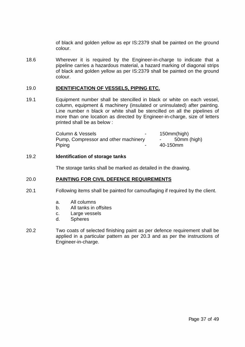
Page 37 of 49
of black and golden yellow as epr IS:2379 shall be painted on the groundcolour.
18.6 Wherever it is required by the Engineer-in-charge to indicate that apipeline carries a hazardous material, a hazard marking of diagonal stripsof black and golden yellow as per IS:2379 shall be painted on the groundcolour.
19.0 IDENTIFICATION OF VESSELS, PIPING ETC.
19.1 Equipment number shall be stencilled in black or white on each vessel,column, equipment & machinery (insulated or uninsulated) after painting.Line number n black or white shall be stencilled on all the pipelines ofmore than one location as directed by Engineer-in-charge, size of lettersprinted shall be as below :
Column & Vessels - 150mm(high)Pump, Compressor and other machinery - 50mm (high)Piping - 40-150mm
19.2 Identification of storage tanks
The storage tanks shall be marked as detailed in the drawing.
20.0 PAINTING FOR CIVIL DEFENCE REQUIREMENTS
20.1 Following items shall be painted for camouflaging if required by the client.
a. All columnsb. All tanks in offsitesc. Large vesselsd. Spheres
20.2 Two coats of selected finishing paint as per defence requirement shall beapplied in a particular pattern as per 20.3 and as per the instructions ofEngineer-in-charge.
Page 38 of 49
20.3 Method of Camouflaging
20.3.1 Disruptive painting for camouflaging shall be done in three colours in theratio of 5:3:2 (all matt finish).
Dark Green Light Green Dark Medium Brown5: 3: 2
20.3.2 The patches should be asymmetrical and irregular.
20.3.3 The patches should be inclined at 30 degree to 60 degree to thehorizontal.
20.3.4 The patches should be continuous where two surfaces meet at an angle.
20.3.5 The patches should not coincide with corners.
20.3.6 Slits and holes shall be painted and dark shades.
20.3.7 Width of patches should be 1 to 2 meters.
21.0 INSPECTION AND TESTING
21.1 All painting materials including primers and thinners brought to site bycontractor for application shall be procured directly from manufacturers asper specifications and shall be accompanied by manufacturer’s testcertificates. Paint formulations without certificates are not acceptable.
21.2 Engineer-in-Charge at his discretion, may call for tests for paintformulations. Contractor shall arrange to have such tests performedincluding batchwise test of wet paints for physical & chemical analysis. Allcosts there shall be borne by the contractor.
21.3 The painting work shall be subject to inspection by Engineer-in-Charge atall times. In particular, following stagewise inspection will be performedand contractor shall offer the work for inspection and approval of everystage before proceeding with the next stage. The record of inspectionshall ne maintained in the registers. Stages of inspection are as follows:
a. Surface preparationb. Primer applicationc. Each coat of paint
Page 39 of 49
In addition to above, record should inculde type of shop primer alreadyapplied on equipment e. g. Redd oxide zinc chromate or zinc chromate orRed lead primer etc.
Any defect noticed during the various stages of inspection shall berectified by the contractor to the entire satisfaction of Engineer-in-Chargebefore proceeding further. Irrespective of the inspection, repair andapproval at intermidiate stages of work. Contractor shall be responsible formaking good any defects found during final inspection/ guarantee period/defect liability period as defined in general condition of contract. Dry filmthickness (DFT) shall be checked and recorded after application of eachcoat and extra coat of paint should be applied to make-up the DFTspecified without any extra cost to owner, the extra cost should have priorapproval of Engineer-in-Charge.
21.4 Primer Application
After surface preparation the primer should be applied to cover thecrevices, corners, sharp edges etc. in the presence of inspectornominated by Engineer-in-Charge.
21.5 The shades of successive coats should be slightly different in colour inorder to ensure application of individual coats, the thickness of each coatand complete coverage should be checked as per provision of thisspecification. This should be approved by Engineer-in-Charge beforeapplication of successive coats.
21.6 The contractor shall provide standard thickness measurement instrumentwith appropriate ranges(s) for measuring.
Dry film thickness of each coat, surface profile guage for checking ofsurface profile in case of blast cleaning. Holiday directors and pinholedetector and positector whenever required for checking in case ofimmersion conditions.
21.7 Prior to application of paints on surface of chimneys the thickness of theindividual coat shall be checked by application of each coat of same painton M. S test panel. The thickness of paint on test panel shall bedetermined by using guage such as ‘Elkomere’. This thickness of eachcoat shall be checked as per provision of this specification. This shall beapproved by Engineer-in-Charge before application of paints on surface ofchimney.
21.8 At the discretion of Engineer-in-Charge, the paint manufacturer mustprovide the expert technical service at site as and when required. Thisservice should be free of cost and without any obligation to the owner, as
Page 40 of 49
it would be in the interest of the manufacturer to ensure that both surfacepreparation and application are carried out as per their recommendations.
21.9 Final inspection shall include measurement of paint dry film thickness.Adhesion Holiday detection check of finish and workmanship. Thethickness should be measured at as many points/ locations as decided byEngineer-in-Charge and shall be within + 10% of the dry thickness,specified in the specifications.
21.10 The contractor shall arrange for spot checking of paint materials for Sp.Gr., flow time (ford cup) and spreading rate.
22.0 GUARANTEE
22.1 The contractor shall guarantee that the chemical and physical propertiesof paint materials used are in accordance with the specifications containedherein/ to be provided during execution of work.
22.2 The contractor shall produce test report from manufacturer regarding thequality of the particular batch of paint supplied. The Engineer-in-Chargeshall have the right the test wet samples of paint at random, for quality ofsame as stipulated in clause 11 above. Batch test report of manufacturer’sfor each batch paint supplied shall be made available by the contractor.
23.0 QUALIFICATION CRITERIA OF PAINTING CONTRACTOR
Painting contractor who is awarded any job for EIL, projects under thisstandard must have necessary equipments, machinery, tool and tacklesfor surface preparation, paint application and inspection. The contractormust have qualified trained and experienced surface preparation, paintapplicator, inspector, and supervisors. The contractor supervisor,inspector surface perpetrator and paint applicator must be conversant withthe standards referred in this specification the contractors capacity,capability and competency requirements for the job shall be quantified inthe tender document and shall be assessed by an EIL team beforeawarding any job.
Page 41 of 49
24.0 PROCEDURE FOR APPROVAL OF NEW COATING MATERIALS ANDMANUFACTURER’S
Following procedure is recommended to be followed for approval of newmanufacturers.
24.1 The manufacturer should arrange testing of the inorganic zinc silicatecoating materials as per the list of tests given in para 24.5 below from oneof the reputed Government laboratories.
24.2 Samples of coating should be submitted to the Govt. laboratory in sealedcontainers with batch no. and test certificate on regular format ofmanufacturer’s testing laboratory. The sampling shall be certificate andsealed by a citifying agency.
24.3 All test panels should be prepared by govt. testing agency colouredphotographs of test panels should be taken before and after the testshould be enclosed alongwith test report.
Sample batch. No. and manufacturer’s test certificate should ne enclosedalongwith the report. Test reports contain details of observation andrusting if any, as per the testing code. Suggested government laboratoriesare:
RRL, HayderabadHBTI, KanpurDMSRDE, KanpurIIT, MumbaiBIS LaboratoryUDCT, MumbaiRITES, CalcuttaPDIL
24.4 Manufacturers should intimate the company, details of sample submittedfor testing name of Govt. testing agency, date, contact personnel of theGovt. testing agency. At the end of the test the manufacturer shouldsubmit the test report to the company for approval. The manufacturer(s)shall be qualified based on the result of these tests and other assessmentand the Company’s decision in this regard shall be final and binding on themanufacturer.
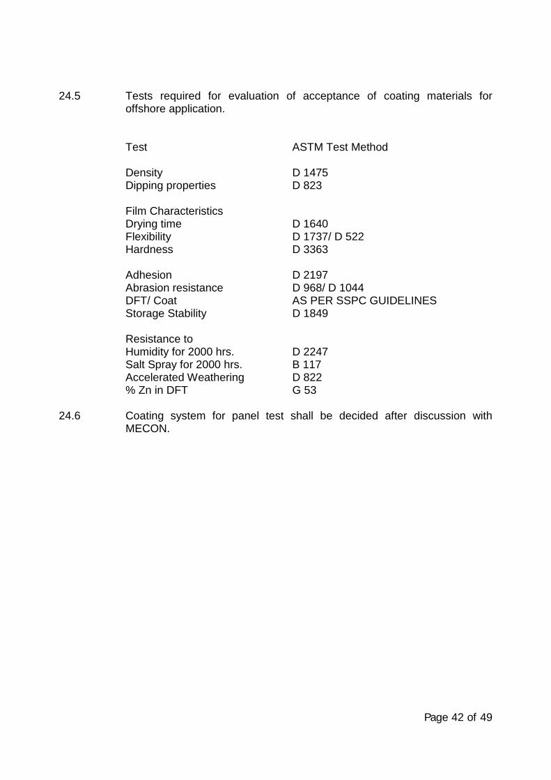
Page 42 of 49
24.5 Tests required for evaluation of acceptance of coating materials foroffshore application.
Test ASTM Test Method
Density D 1475Dipping properties D 823
Film CharacteristicsDrying time D 1640Flexibility D 1737/ D 522Hardness D 3363
Adhesion D 2197Abrasion resistance D 968/ D 1044DFT/ Coat AS PER SSPC GUIDELINESStorage Stability D 1849
Resistance toHumidity for 2000 hrs. D 2247Salt Spray for 2000 hrs. B 117Accelerated Weathering D 822% Zn in DFT G 53
24.6 Coating system for panel test shall be decided after discussion withMECON.
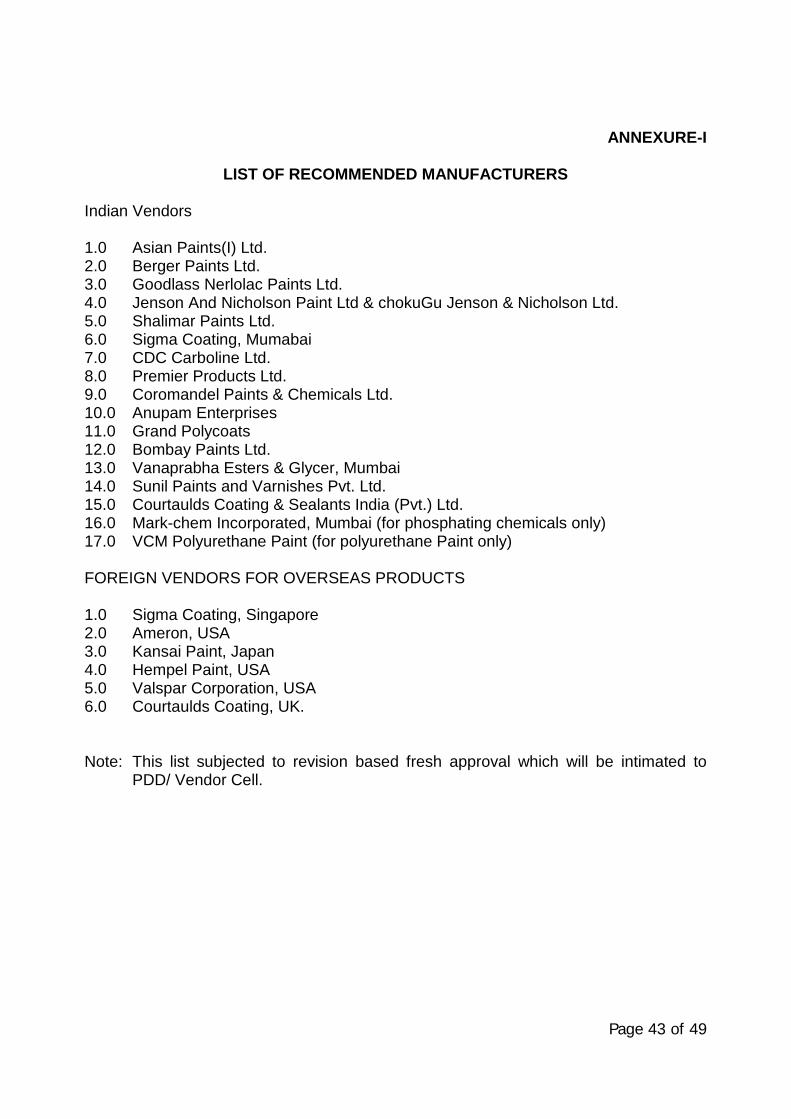
Page 43 of 49
ANNEXURE-I
LIST OF RECOMMENDED MANUFACTURERS
Indian Vendors
1.0 Asian Paints(I) Ltd.2.0 Berger Paints Ltd.3.0 Goodlass Nerlolac Paints Ltd.4.0 Jenson And Nicholson Paint Ltd & chokuGu Jenson & Nicholson Ltd.5.0 Shalimar Paints Ltd.6.0 Sigma Coating, Mumabai7.0 CDC Carboline Ltd.8.0 Premier Products Ltd.9.0 Coromandel Paints & Chemicals Ltd.10.0 Anupam Enterprises11.0 Grand Polycoats12.0 Bombay Paints Ltd.13.0 Vanaprabha Esters & Glycer, Mumbai14.0 Sunil Paints and Varnishes Pvt. Ltd.15.0 Courtaulds Coating & Sealants India (Pvt.) Ltd.16.0 Mark-chem Incorporated, Mumbai (for phosphating chemicals only)17.0 VCM Polyurethane Paint (for polyurethane Paint only)
FOREIGN VENDORS FOR OVERSEAS PRODUCTS
1.0 Sigma Coating, Singapore2.0 Ameron, USA3.0 Kansai Paint, Japan4.0 Hempel Paint, USA5.0 Valspar Corporation, USA6.0 Courtaulds Coating, UK.
Note: This list subjected to revision based fresh approval which will be intimated toPDD/ Vendor Cell.
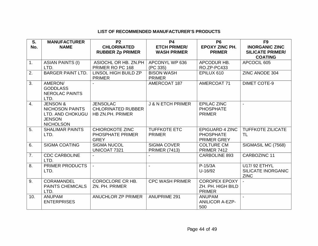
Page 44 of 49
LIST OF RECOMMENDED MANUFACTURER’S PRODUCTS
S.No.
MANUFACTURERNAME
P2CHLORINATED
RUBBER Zp PRIMER
P4ETCH PRIMER/WASH PRIMER
P6EPOXY ZINC PH.
PRIMER
F9INORGANIC ZINC
SILICATE PRIMER/COATING
1. ASIAN PAINTS (I)LTD.
ASIOCHL OR HB. ZN.PHPRIMER RO PC 168
APCONYL WP 636(PC 335)
APCODUR HB.RO.ZP-PC433
APCOCIL 605
2. BARGER PAINT LTD. LINSOL HIGH BUILD ZPPRIMER
BISON WASHPRIMER
EPILUX 610 ZINC ANODE 304
3. AMERON/GODDLASSNEROLAC PAINTSLTD.
- AMERCOAT 187 AMERCOAT 71 DIMET COTE-9
4. JENSON &NICHOSON PAINTSLTD. AND CHOKUGUJENSONNICHOLSON
JENSOLACCHLORINATED RUBBERHB ZN.PH. PRIMER
J & N ETCH PRIMER EPILAC ZINCPHOSPHATEPRIMER
-
5. SHALIMAR PAINTSLTD.
CHIOROKOTE ZINCPHOSPHATE PRIMERGREY
TUFFKOTE ETCPRIMER
EPIGUARD 4 ZINCPHOSPHATEPRIMER GREY
TUFFKOTE ZILICATETL
6. SIGMA COATING SIGMA NUCOLUNICOAT 7321
SIGMA COVERPRIMER (7413)
COLTURE CMPRIMER 7412
SIGMASIL MC (7568)
7. CDC CARBOLINELTD.
- - CARBOLINE 893 CARBOZINC 11
8. PRIMER PRODUCTSLTD.
- - P-15/3AU-16/92
U17/ 92 ETHYLSILICATE INORGANICZINC
9. CORAMANDELPAINTS CHEMICALSLTD.
COROCLORE CR HB.ZN. PH. PRIMER
CPC WASH PRIMER COROPEX EPOXYZH. PH. HIGH BILDPRIMER
-
10. ANUPAMENTERPRISES
ANUCHLOR ZP PRIMER ANUPRIME 291 ANUPAMANILICOR A-EZP-500
-
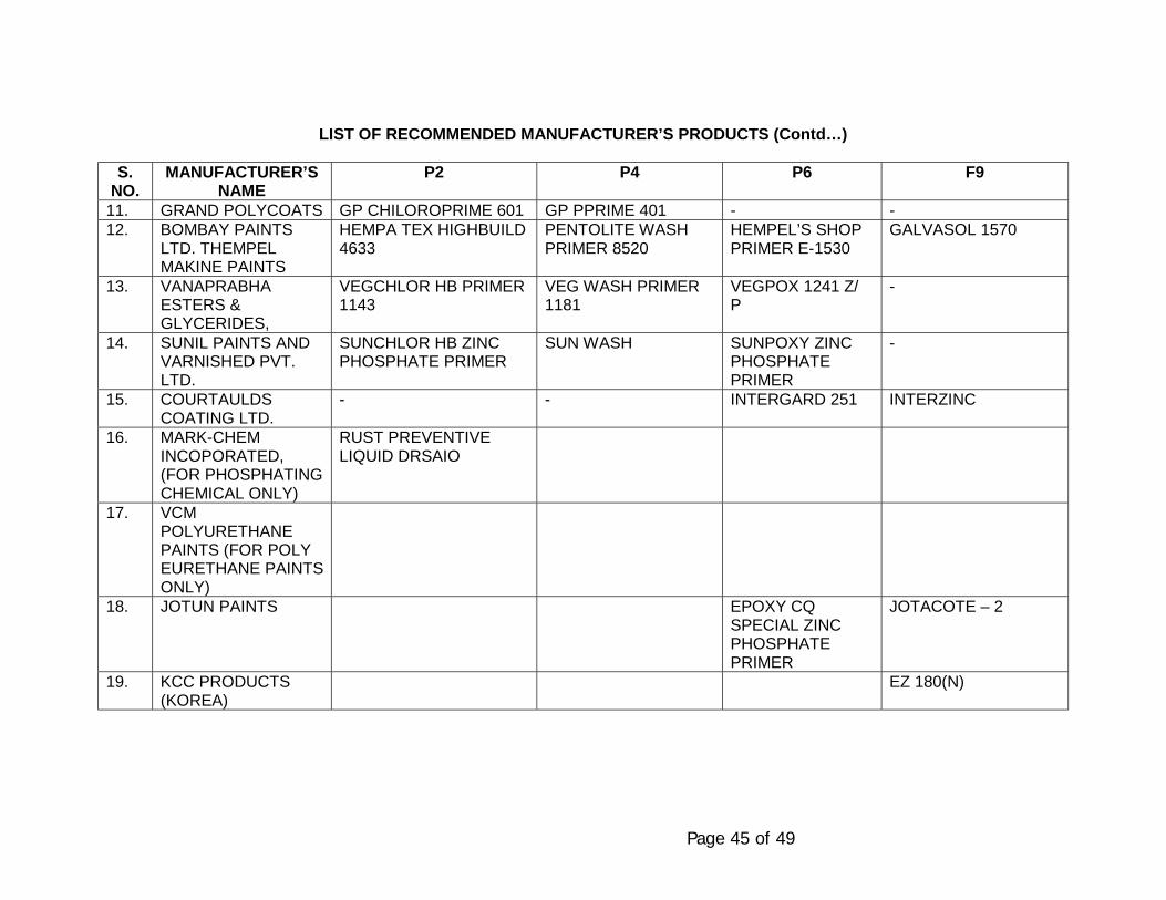
Page 45 of 49
LIST OF RECOMMENDED MANUFACTURER’S PRODUCTS (Contd…)
S.NO.
MANUFACTURER’SNAME
P2 P4 P6 F9
11. GRAND POLYCOATS GP CHILOROPRIME 601 GP PPRIME 401 - -12. BOMBAY PAINTS
LTD. THEMPELMAKINE PAINTS
HEMPA TEX HIGHBUILD4633
PENTOLITE WASHPRIMER 8520
HEMPEL’S SHOPPRIMER E-1530
GALVASOL 1570
13. VANAPRABHAESTERS &GLYCERIDES,
VEGCHLOR HB PRIMER1143
VEG WASH PRIMER1181
VEGPOX 1241 Z/P
-
14. SUNIL PAINTS ANDVARNISHED PVT.LTD.
SUNCHLOR HB ZINCPHOSPHATE PRIMER
SUN WASH SUNPOXY ZINCPHOSPHATEPRIMER
-
15. COURTAULDSCOATING LTD.
- - INTERGARD 251 INTERZINC
16. MARK-CHEMINCOPORATED,(FOR PHOSPHATINGCHEMICAL ONLY)
RUST PREVENTIVELIQUID DRSAIO
17. VCMPOLYURETHANEPAINTS (FOR POLYEURETHANE PAINTSONLY)
18. JOTUN PAINTS EPOXY CQSPECIAL ZINCPHOSPHATEPRIMER
JOTACOTE – 2
19. KCC PRODUCTS(KOREA)
EZ 180(N)
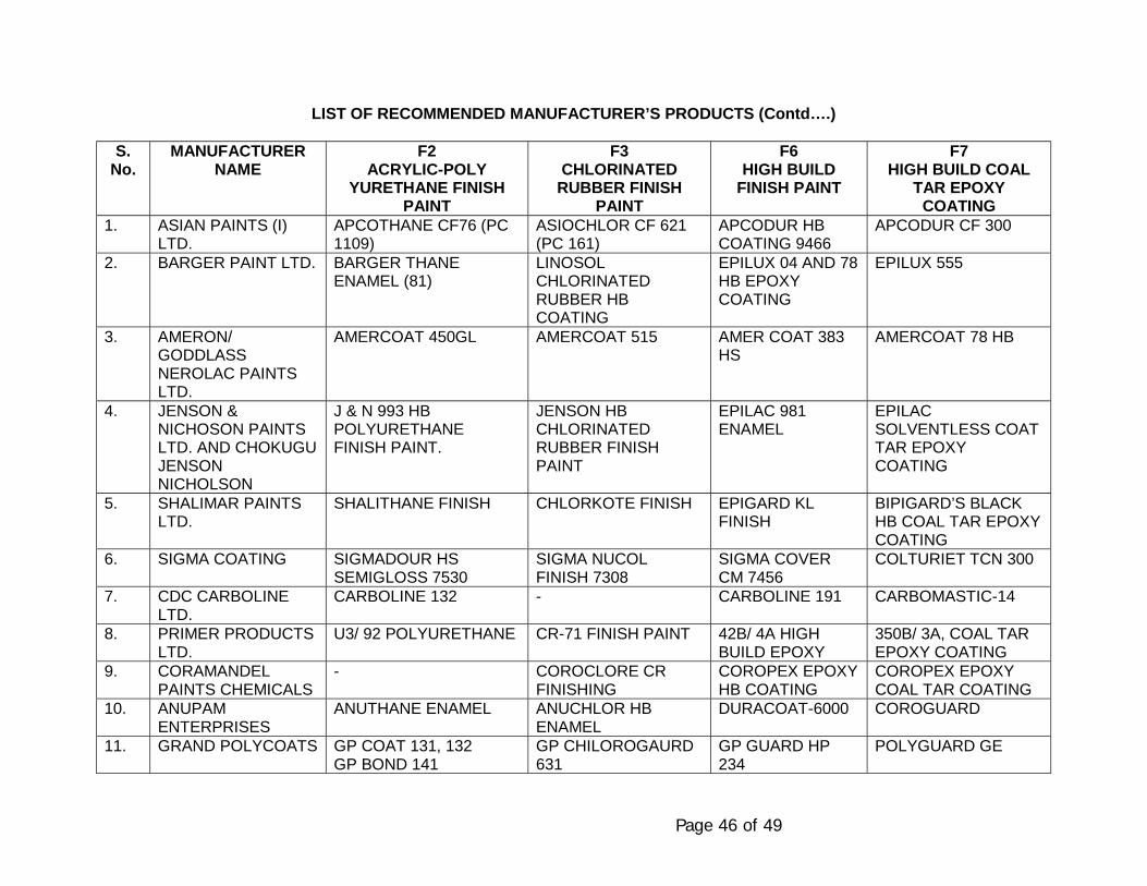
Page 46 of 49
LIST OF RECOMMENDED MANUFACTURER’S PRODUCTS (Contd….)
S.No.
MANUFACTURERNAME
F2ACRYLIC-POLY
YURETHANE FINISHPAINT
F3CHLORINATED
RUBBER FINISHPAINT
F6HIGH BUILD
FINISH PAINT
F7HIGH BUILD COAL
TAR EPOXYCOATING
1. ASIAN PAINTS (I)LTD.
APCOTHANE CF76 (PC1109)
ASIOCHLOR CF 621(PC 161)
APCODUR HBCOATING 9466
APCODUR CF 300
2. BARGER PAINT LTD. BARGER THANEENAMEL (81)
LINOSOLCHLORINATEDRUBBER HBCOATING
EPILUX 04 AND 78HB EPOXYCOATING
EPILUX 555
3. AMERON/GODDLASSNEROLAC PAINTSLTD.
AMERCOAT 450GL AMERCOAT 515 AMER COAT 383HS
AMERCOAT 78 HB
4. JENSON &NICHOSON PAINTSLTD. AND CHOKUGUJENSONNICHOLSON
J & N 993 HBPOLYURETHANEFINISH PAINT.
JENSON HBCHLORINATEDRUBBER FINISHPAINT
EPILAC 981ENAMEL
EPILACSOLVENTLESS COATTAR EPOXYCOATING
5. SHALIMAR PAINTSLTD.
SHALITHANE FINISH CHLORKOTE FINISH EPIGARD KLFINISH
BIPIGARD’S BLACKHB COAL TAR EPOXYCOATING
6. SIGMA COATING SIGMADOUR HSSEMIGLOSS 7530
SIGMA NUCOLFINISH 7308
SIGMA COVERCM 7456
COLTURIET TCN 300
7. CDC CARBOLINELTD.
CARBOLINE 132 - CARBOLINE 191 CARBOMASTIC-14
8. PRIMER PRODUCTSLTD.
U3/ 92 POLYURETHANE CR-71 FINISH PAINT 42B/ 4A HIGHBUILD EPOXY
350B/ 3A, COAL TAREPOXY COATING
9. CORAMANDELPAINTS CHEMICALS
- COROCLORE CRFINISHING
COROPEX EPOXYHB COATING
COROPEX EPOXYCOAL TAR COATING
10. ANUPAMENTERPRISES
ANUTHANE ENAMEL ANUCHLOR HBENAMEL
DURACOAT-6000 COROGUARD
11. GRAND POLYCOATS GP COAT 131, 132GP BOND 141
GP CHILOROGAURD631
GP GUARD HP234
POLYGUARD GE
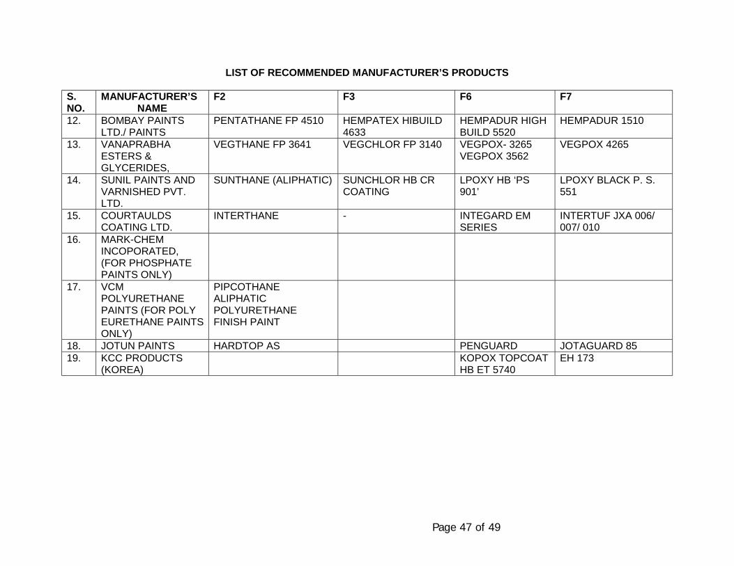
Page 47 of 49
LIST OF RECOMMENDED MANUFACTURER’S PRODUCTS
S.NO.
MANUFACTURER’SNAME
F2 F3 F6 F7
12. BOMBAY PAINTSLTD./ PAINTS
PENTATHANE FP 4510 HEMPATEX HIBUILD4633
HEMPADUR HIGHBUILD 5520
HEMPADUR 1510
13. VANAPRABHAESTERS &GLYCERIDES,
VEGTHANE FP 3641 VEGCHLOR FP 3140 VEGPOX- 3265VEGPOX 3562
VEGPOX 4265
14. SUNIL PAINTS ANDVARNISHED PVT.LTD.
SUNTHANE (ALIPHATIC) SUNCHLOR HB CRCOATING
LPOXY HB ‘PS901’
LPOXY BLACK P. S.551
15. COURTAULDSCOATING LTD.
INTERTHANE - INTEGARD EMSERIES
INTERTUF JXA 006/007/ 010
16. MARK-CHEMINCOPORATED,(FOR PHOSPHATEPAINTS ONLY)
17. VCMPOLYURETHANEPAINTS (FOR POLYEURETHANE PAINTSONLY)
PIPCOTHANEALIPHATICPOLYURETHANEFINISH PAINT
18. JOTUN PAINTS HARDTOP AS PENGUARD JOTAGUARD 8519. KCC PRODUCTS
(KOREA)KOPOX TOPCOATHB ET 5740
EH 173
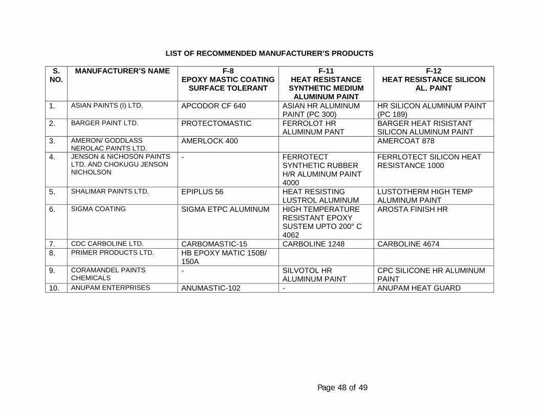
Page 48 of 49
LIST OF RECOMMENDED MANUFACTURER’S PRODUCTS
S.NO.
MANUFACTURER’S NAME F-8EPOXY MASTIC COATING
SURFACE TOLERANT
F-11HEAT RESISTANCE
SYNTHETIC MEDIUMALUMINUM PAINT
F-12HEAT RESISTANCE SILICON
AL. PAINT
1. ASIAN PAINTS (I) LTD. APCODOR CF 640 ASIAN HR ALUMINUMPAINT (PC 300)
HR SILICON ALUMINUM PAINT(PC 189)
2. BARGER PAINT LTD. PROTECTOMASTIC FERROLOT HRALUMINUM PANT
BARGER HEAT RISISTANTSILICON ALUMINUM PAINT
3. AMERON/ GODDLASSNEROLAC PAINTS LTD.
AMERLOCK 400 AMERCOAT 878
4. JENSON & NICHOSON PAINTSLTD. AND CHOKUGU JENSONNICHOLSON
- FERROTECTSYNTHETIC RUBBERH/R ALUMINUM PAINT4000
FERRLOTECT SILICON HEATRESISTANCE 1000
5. SHALIMAR PAINTS LTD. EPIPLUS 56 HEAT RESISTINGLUSTROL ALUMINUM
LUSTOTHERM HIGH TEMPALUMINUM PAINT
6. SIGMA COATING SIGMA ETPC ALUMINUM HIGH TEMPERATURERESISTANT EPOXYSUSTEM UPTO 200° C4062
AROSTA FINISH HR
7. CDC CARBOLINE LTD. CARBOMASTIC-15 CARBOLINE 1248 CARBOLINE 46748. PRIMER PRODUCTS LTD. HB EPOXY MATIC 150B/
150A9. CORAMANDEL PAINTS
CHEMICALS- SILVOTOL HR
ALUMINUM PAINTCPC SILICONE HR ALUMINUMPAINT
10. ANUPAM ENTERPRISES ANUMASTIC-102 - ANUPAM HEAT GUARD
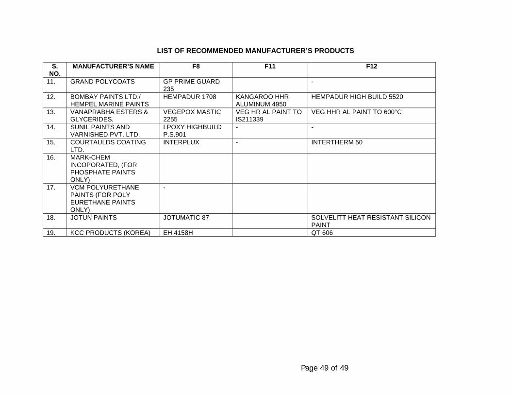
Page 49 of 49
LIST OF RECOMMENDED MANUFACTURER’S PRODUCTS
S.NO.
MANUFACTURER’S NAME F8 F11 F12
11. GRAND POLYCOATS GP PRIME GUARD235
-
12. BOMBAY PAINTS LTD./HEMPEL MARINE PAINTS
HEMPADUR 1708 KANGAROO HHRALUMINUM 4950
HEMPADUR HIGH BUILD 5520
13. VANAPRABHA ESTERS &GLYCERIDES,
VEGEPOX MASTIC2255
VEG HR AL PAINT TOIS211339
VEG HHR AL PAINT TO 600°C
14. SUNIL PAINTS ANDVARNISHED PVT. LTD.
LPOXY HIGHBUILDP.S.901
- -
15. COURTAULDS COATINGLTD.
INTERPLUX - INTERTHERM 50
16. MARK-CHEMINCOPORATED, (FORPHOSPHATE PAINTSONLY)
17. VCM POLYURETHANEPAINTS (FOR POLYEURETHANE PAINTSONLY)
-
18. JOTUN PAINTS JOTUMATIC 87 SOLVELITT HEAT RESISTANT SILICONPAINT
19. KCC PRODUCTS (KOREA) EH 4158H QT 606
SPECIFICATIONFOR
REPAIR OF PIPELINECORROSION COATING
SPECIFICATION NO. MEC/S/05/62/08
(PROCESS & PIPING DESIGN SECTION)MECON LIMITEDDELHI - 110 092
MECON LIMITEDDELHI
PROCESS & PIPINGDESIGN SECTION
NEW DELHI
STANDARD SPECIFICATION
TITLE REPAIR OF PIPELINE CORROSIONCOATING
SPECIFICATION NO. PAGE 1 OF 3
MEC/S/05/62/08 REVISION 0
C O N T E N T S
1. SCOPE
2. MATERIAL AND EQUIPMENT
3. APPLICATION PROCEDURE
4. INSPECTION/ TEST
PREPARED BY CHECKED BY APPROVED BY
MECON LIMITEDDELHI
PROCESS & PIPINGDESIGN SECTION
NEW DELHI
STANDARD SPECIFICATION
TITLE REPAIR OF PIPELINE CORROSIONCOATING
SPECIFICATION NO. PAGE 2 OF 3
MEC/S/05/62/08 REVISION 0 1.0 SCOPE :
This specification covers the minimum requirement of material and equipment,installation procedure and inspection of repair of damaged polyethylene coatingson steel pipes.
1.1 The repair shall be carried out using repair patch made of radiation crosslinkedPolyolefin backing, coated on the inside with semi-crystalline thermoplasticAdhesive and filler mastic
2.0 MATERIAL AND EQUIPMENT
2.1 CONTRACTOR shall supply all ,equipment and manpower required for a skillfuland adequate application in the field in accordance with the specification.
2.2 The repair material shall be :
• Repair patch shall be cross linked polyolefin with semi-crystallinethermoplastic adhesive (PERP patch make of RAYCHEM or equivalent ).
• Filler mastic : PERPFILLER make of RAYCHEM or equivalent.
2.3 The material shall not be older than their period of validity at the time ofApplication by CONTRACTOR. Deteriorated/decomposed materials shall not beused.
2.4 Material shall be stored in sheltered storages in the manufacturer's originalpacking and away from direct sunlight and in accordance with manufacturer'srecommendations.
3.0 APPLICATION PROCEDURE
Application procedure shall be as per manufacturer's recommendations and asper the following guidelines ( ref. Fig: 1 )
Preparation : Remove coating from damaged area with knife, scraper or powerbrush. Scrap off the damaged area and adjacent coating to remove oil, grease,ruse dirt and moisture.
Preheating : Preheat the exposed bare metal surface to about 60°C andadjacent pipe coating to about 47°C with a torch moved back and forth over thesurface.
MECON LIMITEDDELHI
PROCESS & PIPINGDESIGN SECTION
NEW DELHI
STANDARD SPECIFICATION
TITLE REPAIR OF PIPELINE CORROSIONCOATING
SPECIFICATION NO. PAGE 3 OF 3
MEC/S/05/62/08 REVISION 0 Application of the Filler : Plastic filler shall be applied to all exposed metalsurface. The mastic is heated and smoothed down with a paint scraper to coverall bare metal in a manner such that all entrapped air is removed.
Application of repair tape : Cut a patch from the tape in a manner such that itextends 50 mm beyond the damaged area, position it over the damaged area,heat until the temperature sensitive paint on the outside of the patch changescolour. It shall be smoothed down to confirm with the contour of lap, and shallbe freed of any air bubbles or wrinkles.
For cosmetic type of defects such as minor gauging tearing, scratches which donot indicate holiday during holiday inspection, following procedure shall beadopted :
The defect area shall be roughened to remove loose polyethylene coating, oilgrease, dirt etc.
This shall be followed by application of repair patch as described above.
4.0 INSPECTION, TEST
A visual inspection shall be carried out for the following:
- Mastic extrusion on ends of the patch shall be examined.- There shall be no sign of punctures or pin holes or bend failure. The
external appearance of the patch shall be smooth, free from dimples, airentrapment or void formation.
- The entire repair patch shall have changed colour uniformly.
5.0 HOLIDAY INSPECTION
The holiday detector used shall be checked and calibrated easily with anaccurate D.C. Voltmeter. The detector electrode shall be in direct contact withthe surface of coating to be inspected.
The entire surface of the repaired section shall be inspected by means of a fullcircle holiday detector approved by company set to a DC Voltage of at least 25KV. Inspection of repaired patch shall be conducted only after it has cooledbelow 50°C.No repaired point shall be covered or lowered in the trench until it has beenapproved by the COMPANY.
\\Akjha\work contrac\standard TS for Pipe Line WC (Vol-II) MASTER FOLDER\69 documentation for pipeline construction\Specification for Documentation for PL Const - 69.doc
SPECIFICATION
FOR
DOCUMENTATION FOR PIPELINE CONSTRUCTION
SPECIFICATION NO. MEC/S/05/62/09R
(PROCESS & PIPELINE DESIGN SECTION)
MECON LIMITEDDELHI - 110 092
\\Akjha\work contrac\standard TS for Pipe Line WC (Vol-II) MASTER FOLDER\69 documentation for pipeline construction\Specification for Documentation for PL Const - 69.doc
C O N T E N T S
1.0 SCOPE
2.0 RECORDS
3.0 AS-BUILT DRAWINGS AND PIPE BOOK
\\Akjha\work contrac\standard TS for Pipe Line WC (Vol-II) MASTER FOLDER\69 documentation for pipeline construction\Specification for Documentation for PL Const - 69.doc
Page 1 of 8
1.0 SCOPE
1.1 This specification covers the minimum requirements of various records,reports and drawings for all aspects of pipeline construction to beprepared by Contractor and submitted to the Company at intervals asdescribed in this specification and as directed by Company.
1.2 All document required to prepared and submitted by Contractor as perthis specification shall be in addition to the various reports, records,methodology statement, calculation, drawings etc. to be submitted by theContractor for Company’s record, review or approval as per therequirements of all other specification included in the Contract betweenthe Company and Contractor.
1.3 This specification shall be read in conjunction with the conditions of allspecifications and document included in the Contract between Companyand Contractor.
2.0 RECORDS
Contractor shall submit daily, weekly, monthly and after completion to theCompany, various records and reports for Company’s documentationpurpose during and immediately after the construction. This shall asminimum include, but not limited to the following :
2.1 Daily
• Separate progress reports of all crews
• Daily welding results and repairs
• Actual weather conditions
• Application for deviations, if any
\\Akjha\work contrac\standard TS for Pipe Line WC (Vol-II) MASTER FOLDER\69 documentation for pipeline construction\Specification for Documentation for PL Const - 69.doc
Page 2 of 8
• Accidents
• Damages
• Activities required from Company
• Materials Receipts
• Urgently required materials
2.2 Weekly
• Up-to-date list of confirmed site instruction issued by Company
• Materials `taken over’
• Material defects and repairs
• Outstanding activities of Company
• List of installed markers, chainage
• Required approval from Company
• Progress planned
• Reports of manning of all crews, equipment and plant
• Report of equipment and plant
• Report of accidents
• Report of damages
• Report of acquired release, permits
\\Akjha\work contrac\standard TS for Pipe Line WC (Vol-II) MASTER FOLDER\69 documentation for pipeline construction\Specification for Documentation for PL Const - 69.doc
Page 3 of 8
• Priced variations
• Required materials for next month
2.3 Monthly
• Progress report for payment, safety report, report of accidents,security report, health and environment report, material balance,approved deviations.
2.4 Further, Contractor shall supply (for approval if required to the Companywith document such as but not limited :
• Organogram for construction work.
• Bio-data of key personnel (including foremen).
• (Revised) list of address of personnel in particular of medical staff,safety and security offers.
• (Revised) list of approved coaters.
• (Revised) list of approved sub-contractors.
• Time schedule.
• Acquired permits and/ or approvals from Authorities, if any.
• Minutes of meeting with Company with comments, if any.
• Material certificates, material receipt.
• Guarantee from vendors and sub-contractor.
• Calculations, temporary works, bouyance, blasting.
\\Akjha\work contrac\standard TS for Pipe Line WC (Vol-II) MASTER FOLDER\69 documentation for pipeline construction\Specification for Documentation for PL Const - 69.doc
Page 4 of 8
• Drawings issued by Contractor.
• Vendors drawings.
• As-built of route maps, alignment sheets, details drawings andisometric drawings.
• Procedures such as surveying, stacking, fencing.
• Welding procedure qualification records, radiographic procedurequalification, welder qualification.
• Coating procedure.
• Installation of crossings.
• Hydrostatic testing.
• Blasting.
• Radiographic report alongwith original radiographs
• Pipe and welding book.
• Reports
- Material tests (coating, welding, painting)- Computerised Potential Logging Test- Water Samples- Cleaning, Pigging Report before Hydrostatic Test- Hydrostatic Test- Calibration Test- Blasting Trials- Equipment certificate (dead weight tester, instruments,
vessels, equipment)- Manuals
\\Akjha\work contrac\standard TS for Pipe Line WC (Vol-II) MASTER FOLDER\69 documentation for pipeline construction\Specification for Documentation for PL Const - 69.doc
Page 5 of 8
- Major water crossings- Waste disposal- Disposal of water after hydrostatic test.
2.5 Contractor shall submit to company colour photographs of variousconstruction activities/ operations at regular intervals. Size, number andfrequency of the photographs shall be mutually agreed upon at a laterstage. Also Contractor shall make video recordings of all operations rightfrom the start of construction till the completion of the work, covering tothe extent as instructed by Company and submit to Company. Uponcompletion of the work, Contractor and submit edited master tape plus sixcopies of video recording in VHS formats or any format ordered by theCompany. The duration of video recording shall be of ½ hour and shallcover all aspects of the job.
3.0 AS-BUILT DRAWINGS AND PIPE BOOK
3.1 General
Contractor shall prepare “as-built” drawings of all by or on behalf ofCompany issued drawings and of all Contractor work drawings includingvendor drawing, such as but not limited to :
For Pipeline Section :
- Route Maps- Alignment Sheets- Detail Drawings (road, railway, minor water crossings, major water
crossings, valley crossings)- Isometric drawings of installations- Special installation
Further Contractor shall prepare a pipe Weld Book.
\\Akjha\work contrac\standard TS for Pipe Line WC (Vol-II) MASTER FOLDER\69 documentation for pipeline construction\Specification for Documentation for PL Const - 69.doc
Page 6 of 8
If required by the Company, Contractor shall update the diskettes fordrawings issued for construction of the job.
3.2 “As-Built” Drawings
Contractor shall prepare a complete set of “as-built” drawings. From thestart of construction, Contractor shall on daily basis process any changesin two sets of drawings. Deleted parts shall be indicated in red, new partsin blue, remarks in green and unchanged parts in yellow. Said drawingsshall be kept at site and be available to Company at all times. Contractorshall prepare “as-built” drawings based on these data. On completion ofthe work, one revised film transparency of all drawing made “as-built” byContractor containing the “as-built” information shall be handed over toCompany as well as one complete set of CD ROM/ floppy diskettes asspecified by Company.
Contractor shall prepare and submit a specimen of the layout of thedrawings for Company’s approval.
The required measurement for “as-built” drawing shall be executed byContractor by experienced, qualified surveyors.
The surveyors shall daily take care of all measurement required such asbut not limited to:
- Horizontal location of pipeline with regard to deviations andPermanent Grid Pillars.
- Vertical Level with regard to Mean Sea Level of pipeline and grade.- Location and type of bends, fittings etc. and grades, points of
intersection.- Change of wall thickness, materials.- Location and details of valves, insulating flanges, fencing.- Location and details of crossing pipes, vents.- Location and type of coating.- Location and type of weighting, anchoring.- Location and type of markers.
\\Akjha\work contrac\standard TS for Pipe Line WC (Vol-II) MASTER FOLDER\69 documentation for pipeline construction\Specification for Documentation for PL Const - 69.doc
Page 7 of 8
- Location of further appurtenance (Pig-Signallers)- Location of ROU and of pipeline with respect to ROU.- Type of soil.- Type of rock- Type of blasting and ripping.- Sand padding.- Type of road pavement.- Details of bank protection, number of insulators, seals.
Contractor shall also prepare isometric drawings of all installation(facilitates) etc. for which the data as mentioned in or required for thePipe and Welding Book can be identified and these drawings can also beused for material accounting.
3.3 Nameplates of Equipment
All permanent equipment supplied and installed by Contractor shall beprovided with plates by Contractor. All texts shall be submitted toCompany for approval before plates may be manufactured.
3.4 Pipe Book
Every page of the pipe and Welding Book shall mention:
- Data relevant to the project and section there of.- Sequential number.- Length brought forward (for pipes and other materials).- Length to bring forward (for pipes and other materials).
Alignment sheet number and atleast the location thereon of two welds onevery page of the pipe Book.
Further,
- Diameter of pipeline- Length of each pipe
\\Akjha\work contrac\standard TS for Pipe Line WC (Vol-II) MASTER FOLDER\69 documentation for pipeline construction\Specification for Documentation for PL Const - 69.doc
Page 8 of 8
- Wall thickness- Pipe number- Heat number, certificate number- Cut and re-numbered pipe ends- Coating type- Date of stringing- Date of welding- Direction of working- Heat treatment- Equipment used for radiography- Limits of water crossings- Test pressure and date of test.
In order to achieve this, Contractor shall identify all pipe elements.Sample format of Pipe Book shall be submitted for Company approval.
3.5 As-Built Documents
Contractor shall prepare all documents in the prescribed format asindicated below. In addition to the three hard copies, three copies of finaldocuments shall also be submitted in electronic media i.e. CD ROM/ floppydiskettes.
Software used for the preparation of these documents shall be as follows:
Type document Softwarea) Reports/ Documents MS Officeb) Drawings Auto CAD
For the purpose of preparation of as-built drawings, Contractor shallupdate the “Issued for construction” drawings issued by the Company. Itshall be the Contractor’s responsibility to covert the drawings furnished bythe Company in hard copy into CAD drawings including scanning,digitising and converting the drawings into a suitable format compatiblewith the AutoCAD and above. As-built drawings shall be prepared only onAutoCAD drawings.
Document2
SPECIFICATIONFOR
PIPELINE MARKERS
SPECIFICATION NO. MEC/S/05/62/10
(PROCESS & PIPING DESIGN SECTION)MECON LIMITEDDELHI - 110 092
Document2
MECON LIMITEDREGD. OFF: RANCHI (BIHAR)
PROCESS & PIPINGDESIGN SECTION
NEW DELHI
STANDARD SPECIFICATION
TITLE PIPELINE MARKERS SPECIFICATION NO. PAGE 1 OF 4
MEC/S/05/62/10 REVISION 0
C O N T E N T S
1.0 SCOPE
2.0 REFERENCE CODES AND DRAWINGS
3.0 GENERAL
4.0 AERIAL MARKERS
5.0 KILOMETRE MARKERS
6.0 PIPELINE WARNING SIGN
7.0 ROW BOUNDARY MARKERS
8.0 DIRECTION MARKERS
9.0 NAVIGABLE WATERWAY PIPELINE CROSSING WARNING SIGN
REFERENCE DRAWINGS
MECON STANDARD DRAWINGS
MEC/SD/05/62/10/01 : K.M. POSTMEC/SD/05/62/10/02 : TYPICAL ROW BOUNDARY
MARKERMEC/SD/05/62/10/03 : AERIAL MARKERMEC/SD/05/62/10/04 : DIRECTION MARKERMEC/SD/05/62/10/05 : PIPELINE WARNING SIGNMEC/SD/05/62/10/06 : NAVIGABLE WATERWAY PIPELINE
CROSSING WARNING SIGN
PREPARED BY CHECKED BY APPROVED BY
Document2
MECON LIMITEDREGD. OFF : RANCHI (BIHAR)
PROCESS & PIPINGDESIGN SECTION
NEW DELHI
STANDARD SPECIFICATION
TITLE PIPELINE MARKERS SPECIFICATION NO. PAGE 2 OF 4
MEC/S/05/62/10 REVISION 0
1.0 SCOPE
1.1 This specification covers the minimum requirements for supply, fabrication anderection of pipeline markers to be installed by CONTRACTOR at variouslocations along the route of a cross-country pipeline.
1.2 This specification shall be read in conjunction with the conditions of allspecifications and documents included in the CONTRACT between COMPANYand CONTRACTOR.
2.0 REFERENCE CODES
Reference has been made in this specification to the latest revision of thefollowing code :
API RP 1109 : Recommended practice for marking liquid petroleumpipeline facilities.
3.0 GENERAL
3.1 CONTRACTOR shall supply, fabricate and install the pipeline markers along thepipeline route. The locations of markers as indicated in the approved drawingsshall be treated for guidance purposes only and the exact location of themarkers shall be based on AS BUILT drainage and as directed by COMPANY.
3.2 The pipeline markers shall be fabricated and installed in accordance with theMECON standard drawings included herein. Before start of fabrication of themarkers, CONTRACTOR shall prepare and submit for COMPANY's approvalthe detailed scheme for the marker plates as applicable for the project.
3.3 The pipeline markers shall be installed, as far as possible, at locations such thatto cause no hindrance to the regular use of the land or to the traffic.
4.0 AERIAL MARKERS
Aerial markers shall in general in installed along the pipeline at every five (5)kilometres intervals and at places specified by COMPANY. Refer MECONStandard Drawing No. MEC/SD/05/62/10/03 for details.
Document2
MECON LIMITEDREGD. OFF : RANCHI (BIHAR)
PROCESS & PIPINGDESIGN SECTION
NEW DELHI
STANDARD SPECIFICATION
TITLE PIPELINE MARKERS SPECIFICATION NO. PAGE 3 OF 4
MEC/S/05/62/10 REVISION 0
5.0 KILOMETRE MARKERS
Kilometre markers shall in general be installed along the pipeline between theaerial markers at every one (1) kilometre interval. Markers shall indicatecumulative distance in kilometres from the reference station, as directed byCOMPANY. A kilometre marker is not required if the relative length between itslocation and any pipeline warning sign is less than 200 metres. Refer MECONStandard Drawing No. MEC/SD/05/62/10/01 for details.
6.0 PIPELINE WARNING SIGN
Pipeline Warning Sign shall in general be installed at
• National and State Highway Crossings (2 Nos.)
• Other Road Crossings (1 No.)
• Railway Crossings (2 Nos.)
• Minor Water Crossings (less than 15m width) (1 No.)
• Minor Water Crossings (above 15m width) (2 Nos.)
• Major Water Crossings (2 Nos.)
• Valve Station (1 No.)
• And at any other location as shown in the approved drawings and asdirected by the COMPANY.
Pipeline Warning Sign shall identify the existence of the pipeline and display thename of the COMPANY, with an emergency telephone number, as shown inMECON Standard Drawing No. MEC/SD/05/62/10/05 for details.
7.0 ROW BOUNDARY MARKERS
Right-of-Way boundary markers shall be fabricated and installed as per thedrawings at every 250 metres interval along the entire pipeline route. Theseshall be installed on either side of the pipeline alignment to define the ROWboundary limits. These shall also be installed at pipeline turning points tomaintain the continuity of the ROW limits. Refer MECON Standard Drawing No.MEC/SD/05/62/10/02 for details.
Document2
MECON LIMITEDREGD. OFF : RANCHI (BIHAR)
PROCESS & PIPINGDESIGN SECTION
NEW DELHI
STANDARD SPECIFICATION
TITLE PIPELINE MARKERS SPECIFICATION NO. PAGE 4 OF 4
MEC/S/05/62/10 REVISION 0
8.0 DIRECTION MARKERS
Direction markers as shown in MECON Standard Drawing No. shall be installedto identify the significant turning points of the pipeline during aerial traverse. Onedirection marker shall be installed at each turning point, in addition, two moredirection markers shall be installed along the pipeline alignment, one on eitherside of the turning point at 200m from the turning point.
9.0 NAVIGABLE WATERWAY PIPELINE CROSSING WARNING SIGN
The Navigable Waterway Pipeline Crossing Warning Sign shall be fabricated inaccordance with MECON Standard Drawing No. Such Warning Sign shall beinstalled one on each bank of navigable water courses at the pipeline crossinglocation, in lieu of the Pipeline Warning Sign described in clause 6.0 of thisspecification.
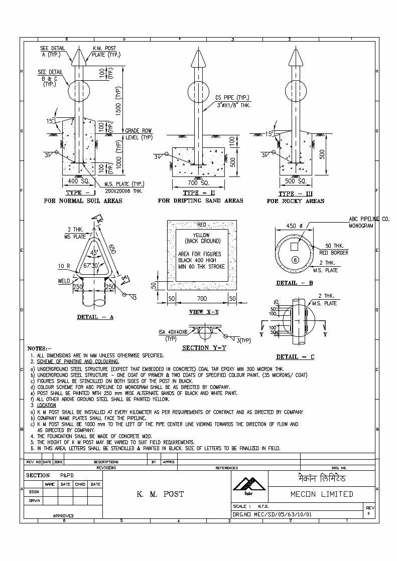
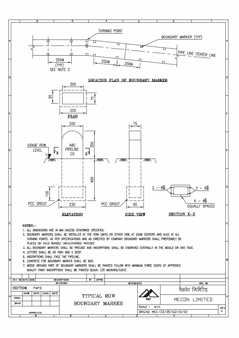
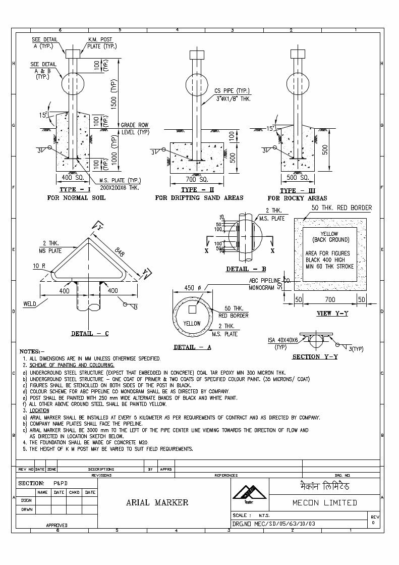
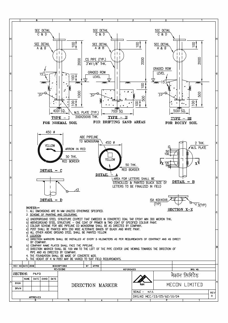
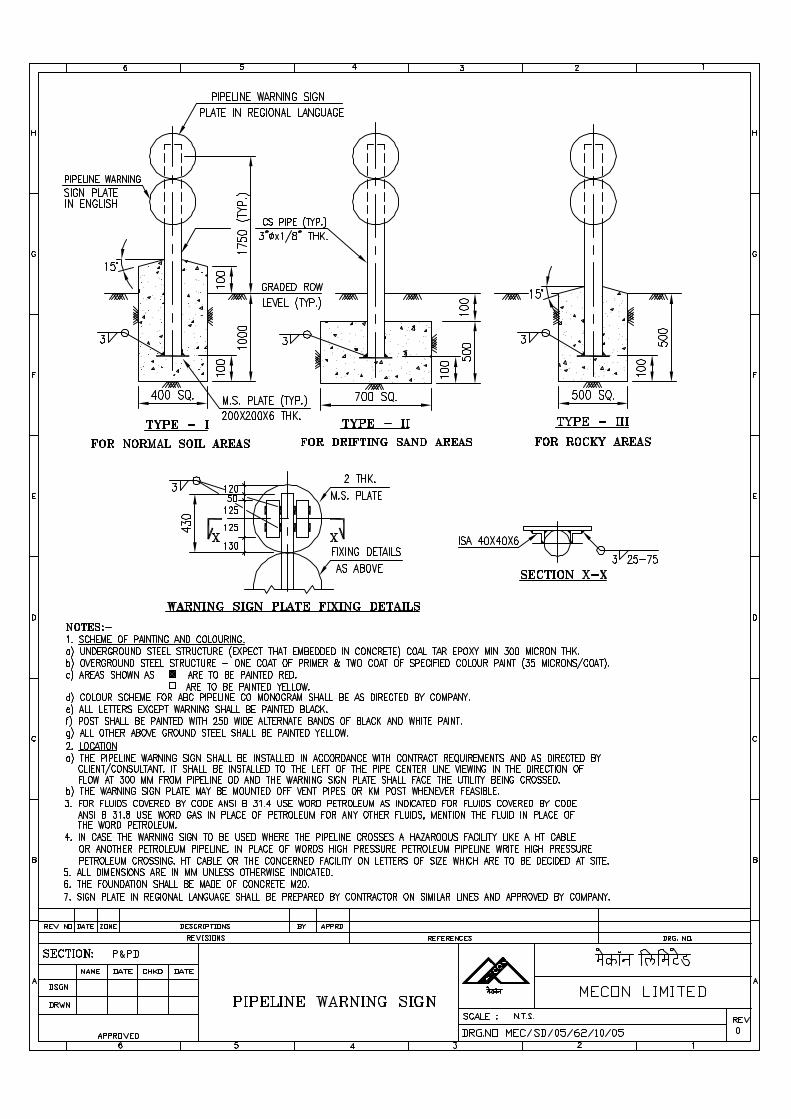
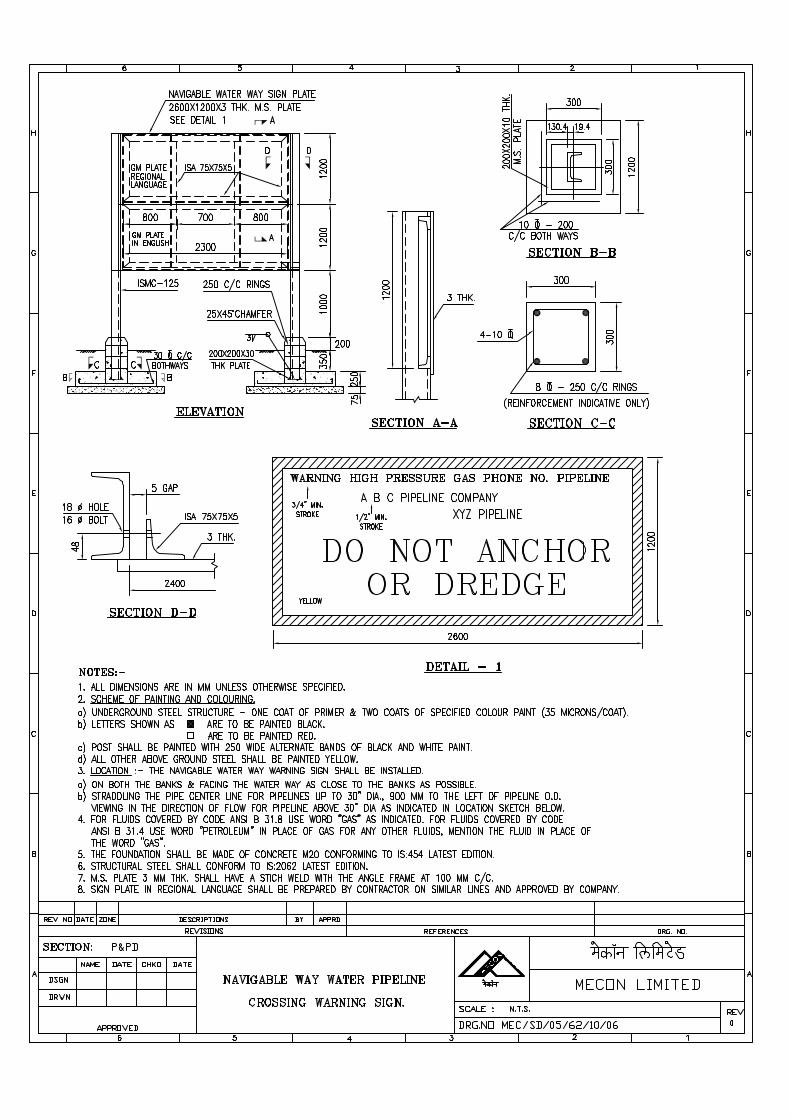
SPECIFICATION FORFLUSHING AND TESTING
SPECIFICATION NO. MEC/S/05/62/11
(PROCESS & PIPING DESIGN SECTION)MECON LIMITEDDELHI 110 092
MECON LIMITEDREGD. OFF: RANCHI (BIHAR)
PROCESS & PIPINGDESIGN SECTION
NEW DELHI
STANDARD SPECIFICATION
TITLE Flushing and Testing SPECIFICATION NO. PAGE 1 OF 9
MEC/S/05/62/11 REVISION 0
C O N T E N T S
1.0 SCOPE
2.0 INSPECTION
3.0 FLUSHING
4.0 TESTING
4.1 EXTENT OF TESTING
4.2 GENERAL REQUIREMENT/TEST PREPARATION FOR TESTING
4.3 TESTING MEDIA, TEST PRESSURE AND TEST PRESSURE GAUGES.
4.4 TESTING PROCEDURE
4.5 COMPLETION OF TESTING
4.6 TEST RECORDS
PREPARED BY CHECKED BY APPROVED BY
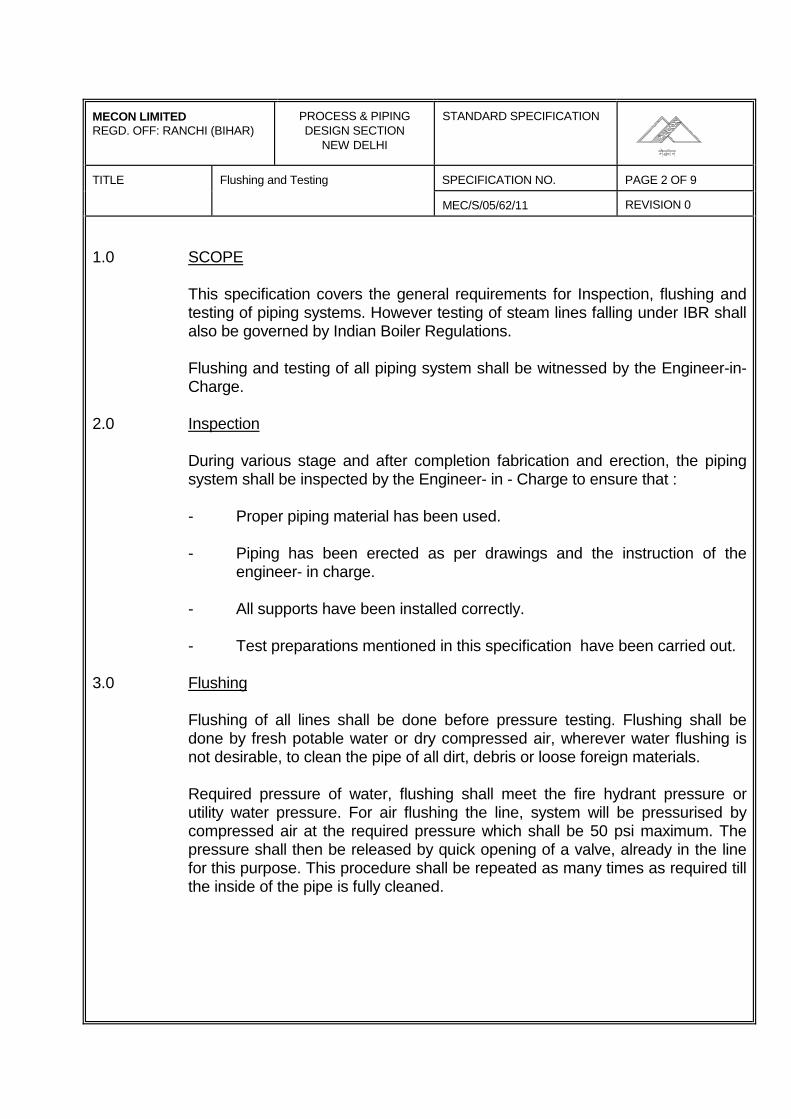
MECON LIMITEDREGD. OFF: RANCHI (BIHAR)
PROCESS & PIPINGDESIGN SECTION
NEW DELHI
STANDARD SPECIFICATION
TITLE Flushing and Testing SPECIFICATION NO. PAGE 2 OF 9
MEC/S/05/62/11 REVISION 0
1.0 SCOPE
This specification covers the general requirements for Inspection, flushing andtesting of piping systems. However testing of steam lines falling under IBR shallalso be governed by Indian Boiler Regulations.
Flushing and testing of all piping system shall be witnessed by the Engineer-in-Charge.
2.0 Inspection
During various stage and after completion fabrication and erection, the pipingsystem shall be inspected by the Engineer- in - Charge to ensure that :
- Proper piping material has been used.
- Piping has been erected as per drawings and the instruction of theengineer- in charge.
- All supports have been installed correctly.
- Test preparations mentioned in this specification have been carried out.
3.0 Flushing
Flushing of all lines shall be done before pressure testing. Flushing shall bedone by fresh potable water or dry compressed air, wherever water flushing isnot desirable, to clean the pipe of all dirt, debris or loose foreign materials.
Required pressure of water, flushing shall meet the fire hydrant pressure orutility water pressure. For air flushing the line, system will be pressurised bycompressed air at the required pressure which shall be 50 psi maximum. Thepressure shall then be released by quick opening of a valve, already in the linefor this purpose. This procedure shall be repeated as many times as required tillthe inside of the pipe is fully cleaned.
MECON LIMITEDREGD. OFF: RANCHI (BIHAR)
PROCESS & PIPINGDESIGN SECTION
NEW DELHI
STANDARD SPECIFICATION
TITLE Flushing and Testing SPECIFICATION NO. PAGE 3 OF 9
MEC/S/05/62/11 REVISION 0
In line instruments like control valves, orifice plates, rotameters, safety valvesand other instruments like thermowells which may interfere with flushing shallnot be included i m the flushing circuit.
From all permanent strainers the screens/meshes shall be removed beforeflushing. Screens/meshes shall be re- installed after flushing but before testing.
In case an equipment such as column, vessel, exchanger etc. forms part of apiping circuit during flushing, this shall be done with the approval of Engineer- in- Charge. However equipment thus included in the circuit, shall be completelycleaned and dried with comprss4ed air, after flushing is completed.
During flushing discharged water/air shall be drained at the place directed theEngineer- in - Charge. If necessary, proper temporary drainage shall beprovided by the contractor.
Care shall be taken during flushing so as not to damage/spoil work of otheragencies. Precautions shall also be taken to prevent entry of water/foreignmatter into equipment, electric motors, instruments, electrical installations etc. inthe vicinity of lines being flushed.
The contractor shall carry out all the activities required before, during and afterthe flushing operation, arising because of flushing requirements, such as but notlimited to the following.
Dropping of valves, specials, distance pieces, online instruments and any otherpiping part before flushing. The flanges to disengaged for this purpose shall beenvisaged by the contractor and approved by the Engineer-in-Charge. Theseflanges shall be provided with temporary gaskets at the time of flushing.
After flushing is completed and approved, the valve, distance pieces, pipingspecials etc. shall be re-installed by the contractor with permanent gaskets.However, flanges of equipment nozzles and other places where isolation isrequired during testing, only temporary gaskets shall be provided.
MECON LIMITEDREGD. OFF: RANCHI (BIHAR)
PROCESS & PIPINGDESIGN SECTION
NEW DELHI
STANDARD SPECIFICATION
TITLE Flushing and Testing SPECIFICATION NO. PAGE 4 OF 9
MEC/S/05/62/11 REVISION 0
Records in triplicate shall be prepared and submitted by the Contractor for eachpiping system for the flushing done in the proforma in Exhibit F.
4.0 Testing
4.1 Extent of testing
With the exclusion of instrumentation. piping system fabricated or assembled inthe field shall be tested irrespective of whether or not they have been pressuretested prior to site welding of fabrication.
To facilitate the testing of piping systems, vessels and other equipments may beincluded in the system with the prior approval of Engineer-in-charge, if the testpressure specified is equal to or less than that for the vessels and otherequipments.
Pumps, compressors and other votary equipments shall not be subjected to fieldtest pressures.
Lines which are directly open to atmosphere such as vents, drains, safetyvalves, discharge need not be tested, but all joints shall be visually inspectedwherever necessary such lines shall be tested by continuous flow of fluid toeliminate the possibility of blockage. However, such lines if provided with blockvalve shall be pressure tested upto the first block valve.
Seats of all vales shall not be subjected to a pressure in excess of the maximumcold welding pressure of the valve. Test pressure applied to vales shall not begrater than the manufacturer is recommendation nor less than that required bythe applicable code. Where desirable set pressure is less than test pressure,test shall be made through an open valve.
Instruments in the system to be tested, shall be excluded from the test byisolation or removal, unless approved otherwise by the Engineer-in-charge. Restrictions which interfere with filling, venting and drawing such as orifice platesetc. shall not be installed unless testing is complete.
Control valves shall not be included in the test system. Where by-passes areprovided test shall be performed through the by-pass end/or necessary spoolshall be used in place of the control valve.
MECON LIMITEDREGD. OFF: RANCHI (BIHAR)
PROCESS & PIPINGDESIGN SECTION
NEW DELHI
STANDARD SPECIFICATION
TITLE Flushing and Testing SPECIFICATION NO. PAGE 5 OF 9
MEC/S/05/62/11 REVISION 0
Pressure gauges which are part of the finished system, but cannot withstandtest pressure shall not be installed until the system has been tested. Wherepiping systems to be tested are directly connected at the battery limits to pipingfor which the responsibility tests with other agencies, the piping to be testedshall be isolated from such piping by physical disconnection such as valves orblinds.
4.2 General Requirement/Test preparation for Testing
Test shall be carried out with permanent gaskets installed unless specifiedotherwise or instructed by the Engineer-in- charge.
No pressure test shall be carried out against close valve unless approved by theEngineer-in-charge.
The Engineer-in-charge shall be notified in advance by the contractor, of thetesting sequence and programme, to enable him to be present for witnessingthe test. The contractor shall be fully responsible for making arrangements withthe local boiler inspector to witness the tests for steam lines falling under IBR. IBR certificates for these tests shall be obtained in the relevant IBR forms andfurnished to the Engineer-in-charge. Before testing, all piping shall be cleanedby flushing to make it free from dist loose scale, debris and other loose foreignmaterials.
All piping systems to be hydrostatically tested shall be vented at the high pointsand the systems purged of air before the test pressure is applied.
Wherever in the line any void is existing due to any reasons, for absence ofcontrol valve, safety valve, check valves etc. it shall be filled with temporaryspools.
All joints welded, screwed or flanged shall be left exposed for examinationduring the test. Before pressuring the lines, each weld joint shall be cleaned bywire brush to free it from rest and any other foreign matter.
Where a system is to be isolated of a pair of companion flanges, a blank shallbe inserted between the companion flanges. Minimum thickness of the blankshall be designed in accordance with applicable design code.
MECON LIMITEDREGD. OFF: RANCHI (BIHAR)
PROCESS & PIPINGDESIGN SECTION
NEW DELHI
STANDARD SPECIFICATION
TITLE Flushing and Testing SPECIFICATION NO. PAGE 6 OF 9
MEC/S/05/62/11 REVISION 0
Open ends of piping system where blanks cannot be used, such as pumps,compressors, turbines or wherever equipment or pipe spool have beenreceivered or disconnected prior to hydrostatic testing, shall be blinded – off byusing standard blind flanges of same rating as the piping system being tested.
Pressure gauges used in testing shall be installed as close as possible to thelowest point in the piping system to be tested, to avoid overstressing of any ofthe lower portion of the system. For longer lines and vertical lines, two or morepressure gauges shall be installed at locations selected by theEngineer-in-charge. For lines containing check valves any of the followingalternatives shall be adopted for pressure testing. Wherever possible pressuriseup-stream side of valve.
Replace the valve by a temporary spool and re-install the valve after testing.
Provide blind on valve flanges and test the upstream and downstream of the lineseparately and remove the blind after testing. All these flanges, temporarygaskets shall be provided during testing and shall be replaced by permanentgaskets subsequently. For check valves in lines 1-1/2" and below, flapper orseat shall be removed during testing (if possible). After completion of testing theflopper/ seat shall be refitted.
Gas lines when hydrostatically tested shall be provided with additional temporarysupports during testing as directed by Engineer-in-charge.
Piping which is spring or counter – weight supported shall be temporarilysupported, where the weight of the fluid would overload the support. Retainingpins for spring supports shall be removed only after testing is completed and testfluid is completely drained.
When testing any piping system, air or steam of approximately 2 kg/cm2 (g) maybe used as preliminary test to detect missing gaskets etc. as this avoids thenecessity of purging the gas to make repairs. However, this method may not beused for this purpose, if the steam temperature is more than the design temp. ofthe line.
MECON LIMITEDREGD. OFF: RANCHI (BIHAR)
PROCESS & PIPINGDESIGN SECTION
NEW DELHI
STANDARD SPECIFICATION
TITLE Flushing and Testing SPECIFICATION NO. PAGE 7 OF 9
MEC/S/05/62/11 REVISION 0
For jacketed pipes testing of core pipes shall be done on individual pieces wherethe pipe is continuously packed, before it is jacketed. The outer jacket shall betested separately as a system for piping with discontinuous jacketing, the eorepipe and the jacket shall be tested as separate system.
4.3 Testing Modes, Test pressure and Test Pressure Gauges
4.3.1 Testing Modes
In general all pressure test shall be hydrostatic using iron free water, which isclean and free of silt. Maximum clorine content in water for hydrostatic testingfor MS piping shall be 15-20 ppm. Air shall be used for testing only if waterwould cause corrosion of the system or overloading of supports etc. in specialcases as directed by Engineer-in-charge.
Where air/water tests are undesirable substitute fluid such as gas, oil, methanoletc. shall be used as the testing medium, with due consideration to the hazardsinvolved. These test fluids shall be specified in the line list given to thecontractor.
4.3.2 Test Pressure
The hydrostatic/pneumatic test pressure shall be as indicated in the line list or asper the instruction of Engineer-in-charge.
The selection of the piping system for one individual test shall be based on thefollowing :-
Test pressure required as per line list.
Maximum allowable pressure for the material of construction of pipingdepending upon the above requirements and based on construction progress,maximum length of piping shall be included in each test.
4.3.3 Test Pressure Gauge
All gauge used for field testing shall have suitable range so that the testpressure of the various system falls in 40% to 60% of gauge scale range. Gauge shall be of a good quality and in first class working condition.
MECON LIMITEDREGD. OFF: RANCHI (BIHAR)
PROCESS & PIPINGDESIGN SECTION
NEW DELHI
STANDARD SPECIFICATION
TITLE Flushing and Testing SPECIFICATION NO. PAGE 8 OF 9
MEC/S/05/62/11 REVISION 0
Prior to the start of any test or periodically during the field test programmes, alltest gauges shall be calibrated using a standard dead weight gauge tester orother suitable approved testing apparatus. Any gauge having an incorrect zeroreading or error of more than ± 2% of full scale range shall be discarded. TheEngineer-in-charge shall check the accuracy of master pressure gauge used forcalibration.
4.4 Testing Pressure
4.4.1 Hydrostatic Test
All vents and other connections used as vents shall be kept open while filling theline with test fluid for complete removal of air. For pressurising anddepressurising the system, temporary isolating valves shall be provided if valves,vents, drains do not exist in the system.
Pressure shall be applied only after the system/line is ready and approved bythe Engineer-in-charge.
Pressure shall be applied by means of a suitable test pump or other pressuresource which shall be isolated from the system as the desired test pressure isreached and stabilised in the system.
A pressure gauge shall be provided at the pump discharge for guiding thesystem to the required pressure.
The pump shall be attended constantly during the test by an authorised person. The pump shall be isolated from the system wherever the pump is to be leftunattended.
Test pressure shall be maintained for a sufficient length of time to permitthrough inspection of all joints for leakage or signs of failure. Any joint foundleaking during a pressure test, shall be re-tested to the specified pressure afterrepair. Test period shall be maintained for a minimum of three hours.
The pump and the piping system to be tested are to be provided with separatepressure indicating test gauges. There gauges are to be checked by thestandard test gauge before each pressure test.
MECON LIMITEDREGD. OFF: RANCHI (BIHAR)
PROCESS & PIPINGDESIGN SECTION
NEW DELHI
STANDARD SPECIFICATION
TITLE SPECIFICATION NO. PAGE 10 OF 10
Flushing and Testing MEC/S/05/62/11 REVISION 0
Care shall be taken to avoid increase in the pressure due to atmosphericvariation during the test.
4.4.2 Air Test
When testing with air, pressure shall be supplied by means of a compressor. The compressor shall be portable type with a receiver after cooler & oilseparator.
Piping to be tested by air shall have joints covered with a soap and watersolution so that the joints can be examined for leaks.
All other activities shall be same as per hydrotesting procedure (specifiedabove).
4.5 Completion of Testing
After the hydrostatic test has been completed, pressure shall be released in amanner and at a rate so as not to endanger personnel or damage equipments.
All vents and drains shall be opened before the system is to be drained andshall remain open till all draining is complete, so as to prevent formation ofvacuum in the system. After draining lines/systems shall be dried by air.
After testing is completed the test blinds shall be removed and equipment/pipingisolated during testing shall be connected using the specified gaskets, bolts andnuts. These connections shall be checked for tightness in subsequentpneumatic tests to be carried out by the contractor for complete loop/circuitincluding equipments (except rotary equipments).
Pressure tests shall be considered complete only after approved by theEngineer-in-charge. Defects, if any, noticed during testing shall be rectifiedimmediately and retesting of the system/line shall be done by the contractor athis cost.
4.6 Test Records
Records in triplicate shall be prepared and submitted by the contractor for eachpiping system, for the pressure test done in the proforma as given in Exhibit `F'.
Document3
SPECIFICATIONFOR
CASING INSULATORSAND END SEALS
SPECIFICATION NO. MEC/S/05/62/12
(PROCESS & PIPING DESIGN SECTION)MECON LIMITEDDELHI - 110 092
Document3
MECON LIMITEDREGD. OFF: RANCHI (BIHAR)
PROCESS & PIPINGDESIGN SECTION
NEW DELHI
STANDARD SPECIFICATION
TITLE SPECIFICATION NO. PAGE 1 OF 6CASING INSULATORS AND END
SEALS MEC/S/05/62/12 REVISION 0
C O N T E N T S
PART-A CASING INSULATIONS
1.0 SCOPE
2.0 FUNCTION
3.0 DESIGN
4.0 MATERIAL
5.0 INSPECTION AND TESTING
PART-B CASING END-SEALS
1.0 SCOPE
2.0 FUNCTION
3.0 DESIGN
4.0 MATERIAL
5.0 INSPECTION AND TESTING
PART-C SUPPLEMENTARY REQUIREMENTS
PREPARED BY CHECKED BY APPROVED BY
Document3
MECON LIMITEDREGD. OFF : RANCHI (BIHAR)
PROCESS & PIPINGDESIGN SECTION
NEW DELHI
STANDARD SPECIFICATION
TITLE SPECIFICATION NO. PAGE 2 OF 6CASING INSULATORS AND END
SEALS MEC/S/05/62/12 REVISION 0
PART-A CASING INSULATORS
1.0 SCOPE
This specification covers the minimum requirements of design, material,manufacture and supply of casing insulators intended to be used for casedpipeline crossings.
2.0 FUNCTION
Pipeline insulators shall be used to support the carrier pipe inside the casingpipe and electrically isolate the carrier pipe from the casing pipe at the casedcrossings.
The casing insulators shall:
- Resist cold flow and will not soften at design temperature.
- Resist corrosion
- Resist mechanical damage while being pulled into the casing.
- Have high electrical insulating value and low water absorption, thuspreventing leakage and maintain electrical isolation between carrier andcasing pipes
- Have high compressive strength in order to assure a permanent supportto the carrier pipe.
3.0 DESIGN
The arrangement of insulator shall be generally in accordance with Fig. 3.0. Itshall be made in segments duly held together with cadmium plated bolts andnuts, to be supplied with casing insulators.
The number of segments shall be two for pipe diameters upto 12” (generally).For larger diameters, the number of segments may be more than two, but theirnumber shall be kept minimum.
The skid height shall be such that it is slightly less than the value obtained byfollowing formula.
Document3
MECON LIMITEDREGD. OFF : RANCHI (BIHAR)
PROCESS & PIPINGDESIGN SECTION
NEW DELHI
STANDARD SPECIFICATION
TITLE SPECIFICATION NO. PAGE 3 OF 6CASING INSULATORS AND END
SEALS MEC/S/05/62/12 REVISION 0
Casing internal dia-carrier outer dia2
Manufacturer shall obtain prior approval from COMPANY on casing insulatorsdrawings/designs.
4.0 MATERIAL
Casing insulators shall be made of injection moulded high density polyethyleneor other material equivalent or superior as approved by COMPANY and shallmeet the following specifications:
Property Value ASTM Test Method
Dielectric strength 450-500 Volts/Mil D-149
Compresssive strength 3200 psi D-695i
Tensile strength 3100-5000 D-638, D-651
Impact strength 4.Oft. 1b./inch of notch D-256
Water Absorption 0.01% D-570
5.0 INSPECTION AND TESTING
Manufacturer shall furnish material test certificates of the components used inthe assembly of casing insulations as per the requirements of clause 4.0 of thisspecification.
Document3
MECON LIMITEDREGD. OFF : RANCHI (BIHAR)
PROCESS & PIPINGDESIGN SECTION
NEW DELHI
STANDARD SPECIFICATION
TITLE SPECIFICATION NO. PAGE 4 OF 6CASING INSULATORS AND END
SEALS MEC/S/05/62/12 REVISION 0
PART-B CASING END-SEALS
1.0 SCOPE
This specification covers the minimum requirements of design, material,fabrication and supply of casing end-seals intended to be used for pipelinecased crossings.
2.0 FUNCTION
Casing end seals are intended to be used for sealing the annular spacebetween casing pipe and carrier pipe at casing ends so as to prevent ingressof moisture and water.
3.0 DESIGN
The scale shall be suitable for the casing and carrier pipe diameters asapplicable for each case.
The casing end-seal shall be flexible to cater for the expansion and contractionof carrier and casing pipes and shall be able to tolerate both angular andconcentric misalignment of casing pipe without loss of sealing efficiency.
The design of the casing end-scale shall permit easy installation of the seal tothe cased pipeline crossing.
It shall provide moisture-proof seals when installed for the entire anticipatedlife of the buried pipeline.
Manufacturer shall obtain prior approval from COMPANY on casing end sealsdesign/drawings.
4.0 MATERIAL
The casing end-scale shall be made of head shrink high density radiationcrosslinked polyethylene with an adhesive having a melt point suitable for thepipeline service temperature and ambient temperatures foreseen duringconstruction. End-seals material shall be resistant to heat, cold, vibration,impact, abrasion, corrosive fluids, disbonding, organic and bio-deterioration.Manufacturer shall confirm compatibility of end seals with carrier pipe coating.
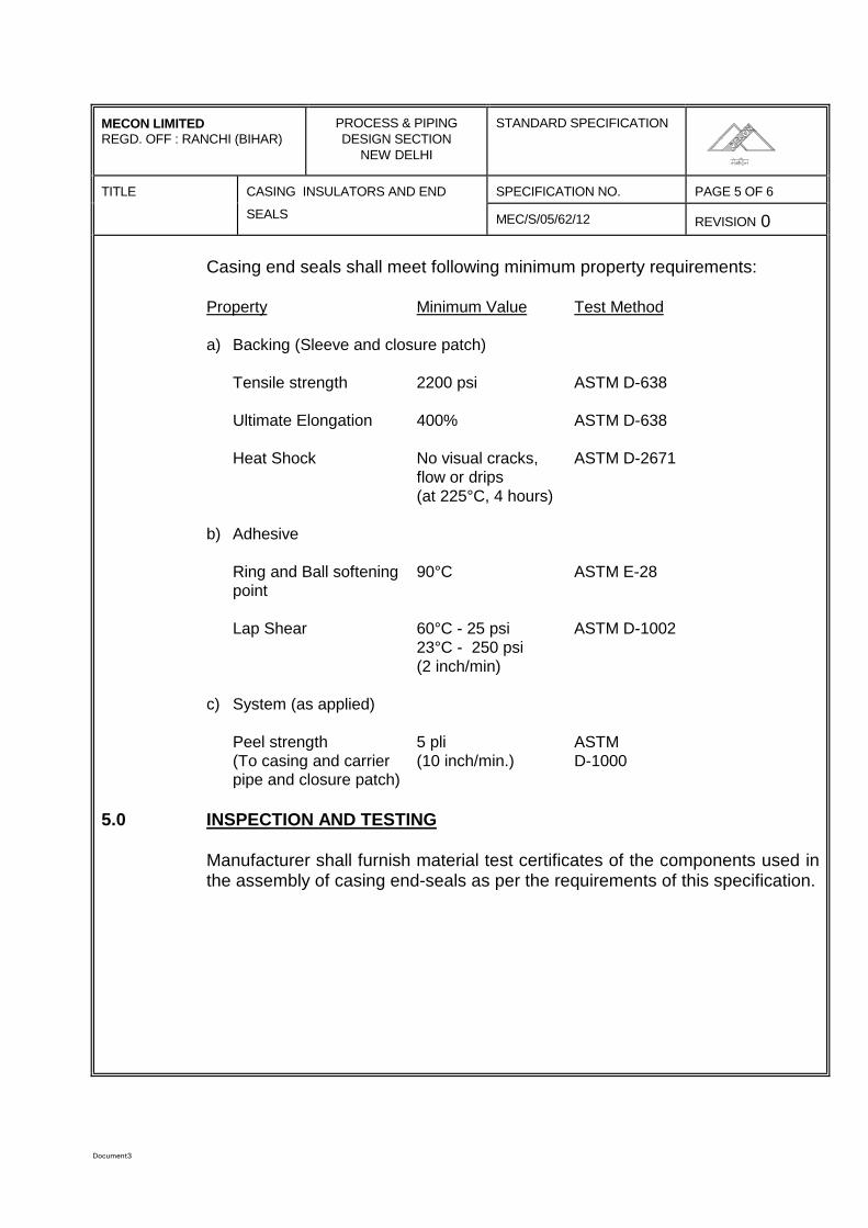
Document3
MECON LIMITEDREGD. OFF : RANCHI (BIHAR)
PROCESS & PIPINGDESIGN SECTION
NEW DELHI
STANDARD SPECIFICATION
TITLE SPECIFICATION NO. PAGE 5 OF 6CASING INSULATORS AND END
SEALS MEC/S/05/62/12 REVISION 0
Casing end seals shall meet following minimum property requirements:
Property Minimum Value Test Method
a) Backing (Sleeve and closure patch)
Tensile strength 2200 psi ASTM D-638
Ultimate Elongation 400% ASTM D-638
Heat Shock No visual cracks, ASTM D-2671flow or drips(at 225°C, 4 hours)
b) Adhesive
Ring and Ball softening 90°C ASTM E-28point
Lap Shear 60°C - 25 psi ASTM D-100223°C - 250 psi(2 inch/min)
c) System (as applied)
Peel strength 5 pli ASTM(To casing and carrier (10 inch/min.) D-1000pipe and closure patch)
5.0 INSPECTION AND TESTING
Manufacturer shall furnish material test certificates of the components used inthe assembly of casing end-seals as per the requirements of this specification.
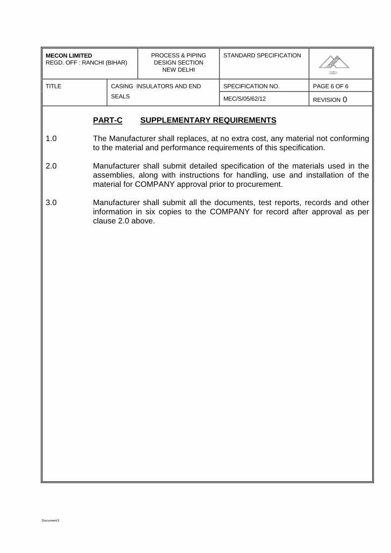
Document3
MECON LIMITEDREGD. OFF : RANCHI (BIHAR)
PROCESS & PIPINGDESIGN SECTION
NEW DELHI
STANDARD SPECIFICATION
TITLE SPECIFICATION NO. PAGE 6 OF 6CASING INSULATORS AND END
SEALS MEC/S/05/62/12 REVISION 0
PART-C SUPPLEMENTARY REQUIREMENTS
1.0 The Manufacturer shall replaces, at no extra cost, any material not conformingto the material and performance requirements of this specification.
2.0 Manufacturer shall submit detailed specification of the materials used in theassemblies, along with instructions for handling, use and installation of thematerial for COMPANY approval prior to procurement.
3.0 Manufacturer shall submit all the documents, test reports, records and otherinformation in six copies to the COMPANY for record after approval as perclause 2.0 above.
SPECIFICATIONFOR
VENTS, DRAINS AND WELLS
SPECIFICATION NO.: MEC/S/05/62/15
(PROCESS & PIPING DESIGN SECTION)MECON LIMITED
DELHI 110 092
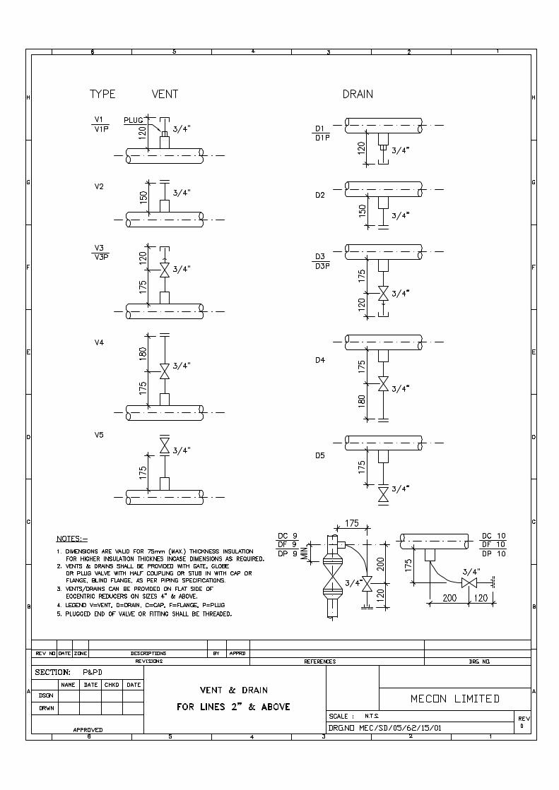
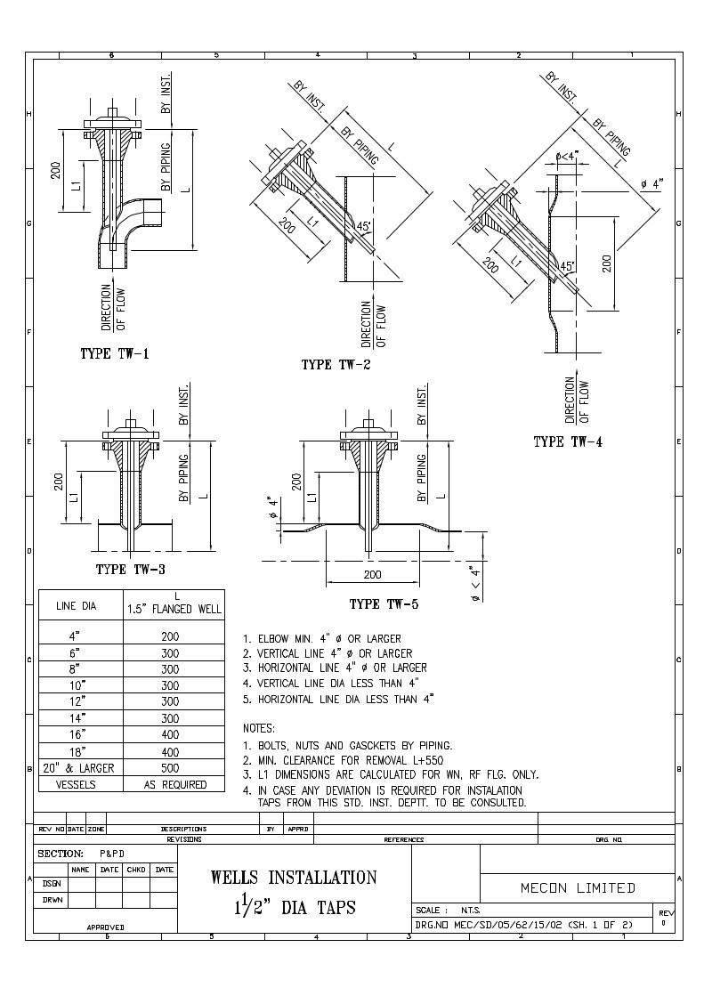
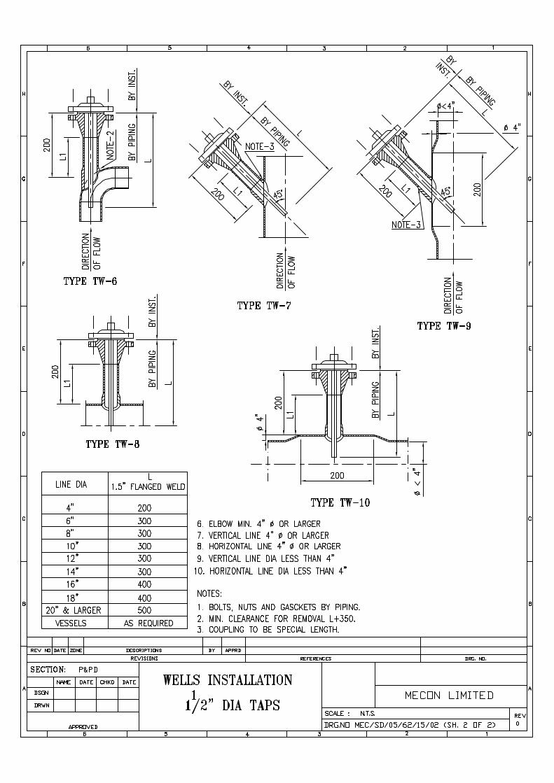
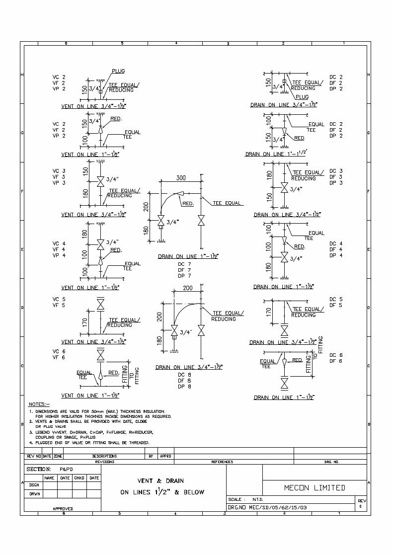
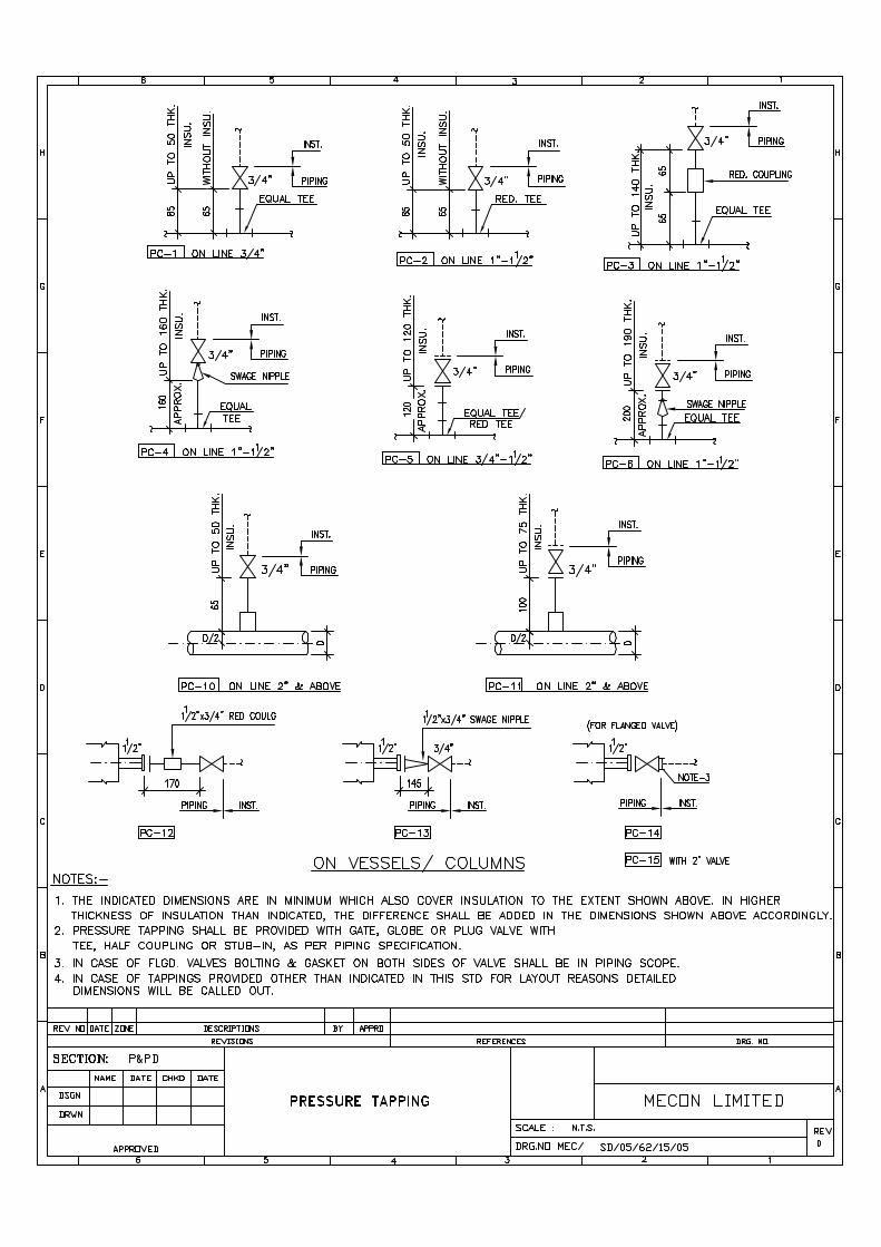
c:\fateh\standard\gas-b&n.wp
SPECIFICATION FORGASKETS, BOLTS & NUTS
SPECIFICATION NO. MEC/S/05/62/19
(PROCESS & PIPING DESIGN SECTION)MECON LIMITED
NEW DELHI 110 016
AUGUST,1999
c:\fateh\standard\gas-b&n.wp
MECON LIMITEDREGD. OFF: RANCHI (BIHAR)
PROCESS & PIPINGDESIGN SECTION
NEW DELHI
STANDARD SPECIFICATION
TITLE GASKETS, BOLTS AND NUTS SPECIFICATION NO. PAGE 1 OF 3
MEC/S/05/62/19 REVISION 0
C O N T E N T S
1.0 GASKETS
2.0 NUTS AND BOLTS
PREPARED BY CHECKED BY APPROVED BY
c:\fateh\standard\gas-b&n.wp
MECON LIMITEDREGD. OFF: RANCHI (BIHAR)
PROCESS & PIPINGDESIGN SECTION
NEW DELHI
STANDARD SPECIFICATION
TITLE GASKETS, BOLTS AND NUTS SPECIFICATION NO. PAGE 2 OF 3
MEC/S/05/62/19 REVISION 0
TECHNICAL NOTES FOR GASKETS
1. Materials for gaskets shall conform to the codes/ standards and specifications given inthe Pipeline Material Specification.
2. Asbestos filler for spiral wound gaskets shall not have any colour or dye.
3. Each size of gaskets shall be supplied in bundles labelled with size, rating and materialspecifications.
4. All gaskets shall be inspected as follows :-
a) Visual Inspection
b) Dimensional Check
5. Material test certificates for all mandatory tests as per the relevant materialspecifications and other inspection reports shall be furnished before despatch ofmaterial.
6. All items shall be inspected and approved (Stagewise) by Purchaser's Representative.
c:\fateh\standard\gas-b&n.wp
MECON LIMITEDREGD. OFF: RANCHI (BIHAR)
PROCESS & PIPINGDESIGN SECTION
NEW DELHI
STANDARD SPECIFICATION
TITLE GASKETS, BOLTS AND NUTS SPECIFICATION NO. PAGE 3 OF 3
MEC/S/05/62/19 REVISION 0
TECHNICAL NOTES FOR BOLTS & NUTS
1. Materials for stud bolts, M/C bolts, jack screws and nuts shall conform to the codes/standards and specifications given in the Pipeline Material Specification.
2. Test reports shall be supplied for all mandatory tests as per the relevant materialspecifications.
3. All bolting shall be as per ANSI B18.2.1 for studs, M/C Bolts and Jack screws and ANSIB18.2.2 for nuts.
4. Threads shall be unified (UNC for = 1" dia and BUN for C1" dia) as per ANSI B1.1 withclass 2A fit for studs, M/C bolts and jack screws and class 2B fit for nuts.
5. Stud bolts shall be fully threaded as specified in the standards, codes.
6. The nuts shall be double chamfered, heavy hexagonal type.
7. Heads of jack screws and M/C bolts by heavy hexagonal type. Jack screw end shall berounded.
8. Each size of studs & M/C bolts with nuts and jack screws shall be supplied in separatebags marked with size and material specifications.
9. All items shall be inspected and approval (Stagewise) by Purchaser's Representative.
PIPING MATERIAL SPECIFICATION
SPECIFICATION NO. MEC/S/05/62/21B
(PROCESS & PIPELINE DESIGN SECTION)MECON LIMITED
DELHI - 110 092
TABLE OF CONTENTS
1.0 SCOPE
2.0 CODES AND STANDARDS
3.0 MATERIAL SPECIFICATION
4.0 CLASS DESIGNATION CODE
5.0 PIPELINE
6.0 PIPING
7.0 FITTINGS
8.0 BENDS
9.0 FLANGES
10.0 GASKETS
11.0 BOLTING
12.0 THREAD SEALANT
13.0 VALVES
14.0 QUICK OPENING END CLOSURE
15.0 HYDROTESTING VENTS AND DRAINS
TABLE-1 PIPE WALL THICKNESS DETAILS FOR LINE
TABLE-2 INDEX OF PIPING MATERIAL SPECIFICATION
ANNEXURE-1 PIPING MATERIAL SPECIFICATION
ANNEXURE-II LIST OF ATTACHMENTS
\\Akjha\work contrac\standard TS for Pipe Line WC (Vol-II) MASTER FOLDER\21B piping material spec\Specification for Piping Materials-021B.doc Page 1 of 6
1.0 SCOPE
This specification covers the requirements of various piping materialsused in piping/ pipeline system handling natural gas and associate utilitiesin the pipeline.
2.0 CODES AND STANDARDS
2.1 Pipeline and terminal facilities envisaged as a part of this project shall bedesigned and Engineered primarily in accordance with the provision ofASME B 31.8- Gas Transmission and Distribution piping system 1995edition.
2.2 All codes standards and specifications referred herein shall be the latestedition of such documents.
2.3 For sake of brevity, the intials of the society to which the codes arereferred are omitted in the specification, for example, B16.5 is a codereferring to ANSI/ ASME, A 105 is a code referring to ASTM.
2.4 In addition, MECON specifications for various piping and pipelinematerials shall also be applicable.
3.0 MATERIAL SPECIFICATION
Piping material specifications are classified for the general purpose ofselection of material for the class of services. The maximum designpressure and design temperature together with the fluid in line governs theselection of material specifications. Deviation of materials from classspecifications may occure due to specific design condition. Thesedeviations are permissible if they are equal or better than the individualclass requirements.
4.0 CLASS DESIGNATION CODE
The piping class designation consist of three digits numbering systemmade up of letter, number, letter e. g. A1A, B1A, D1A, etc as follows:
First letter indicates ANSI class rating e. g.A-Class 150B-Class 300D-Class 600
The middle number indicates differences in the specification within thesame rating and material.
\\Akjha\work contrac\standard TS for Pipe Line WC (Vol-II) MASTER FOLDER\21B piping material spec\Specification for Piping Materials-021B.doc Page 2 of 6
The last letter indicates type of material e. g..
A-Carbon Steel
5.0 PIPELINE
The material for linepipe shall be as per the requirements of specificationas indicated in table-I.
6.0 PIPING
6.1 Carbon steel pipe shall be made by open hearth, electric furnace or basicoxygen process only. The steel used shall be fully killed and made withfine grain structure. The grade and wall thickness of various sizes of pipesshall be as per piping material specification for the applicable class.
6.2 Pipe dimension shall be in accordance with ANSI B 36.10 for carbon steelpipes and ANSI B 36.19 for stainless steel pipes.
6.3 All pipe threads shall conform to American Standard taper as per ANSI B1.20.1 NPT, unless otherwise specified.
6.4 For butt weld end, bevel shall be in accordance to ANSI B 16.25/ API 5Las applicable.
7.0 FITTINGS
7.1 Fully killed carbon steel shall be used in the manufacture of fittings.
7.2 Threaded joints, if used shall conform to American Standard taper as perANSI 1.20.1 NPT.
7.3 Dimension of socket weld/ screwed fittings shall conform to ASME B 16.11
7.4 Bore of socket welded fittings shall suit O. D. of pipe and its thickness.
7.5 Dimensions of butt welded carbon steel fittings upto size 18” NB shallconform to ASME B 16.9/ MSS-SP-75 as applicable.
7.6 Butt welding ends shall conform to ANSI B 16.25/ API 5L. in case ofdifference in thickness of matching ends, requirements of ASME B 31.8shall apply.
\\Akjha\work contrac\standard TS for Pipe Line WC (Vol-II) MASTER FOLDER\21B piping material spec\Specification for Piping Materials-021B.doc Page 3 of 6
7.7 Integrally reinforced forged branch fittings such as sockolet, threadolet,weldolet, nippolet etc. shall be as per MSS-SP-97. Fittings not covered inASME B 16.9 and MSS-SP-97, shall conform to manufacturer’s standard.
8.0 BENDS
8.1 Unless otherwise specified for terminal piping, the elbow of radius R = 1.5D shall only be used.
8.2 For pipeline cold field bends with radius R = 40D (where D is pipe O. D)for 18” NB shall be used. Limited used of long radius bends (R = 6D) maybe permitted for reason of space constraints.
9.0 FLANGES
9.1 Flange rating shall be same as ANSI class rating unless othewisespecified.
9.2 Dimensions pf flanges shall be in accordance with ANSI B 16.5 for sizesup to 18” NB.
9.3 Neck of Weld Neck (WN) flanges to suit pipe bore and thickness.
9.4 Bore of Socket Welded (SW) flanges shall suit pipe O.D. and its thickenss.
9.5 Threads for screwed flanges if used shall conform to American Standardtaper as per ANSI B 1.20 1 NPT.
9.6 Sizes for blind flanges shall be indicated by nominal pipe sizes.
9.7 Carbon steel flanges faces shall have serrated finish or smooth finish asindicated in the material specification. Flanges faces shall have serratedfinish to 250-500 microinches AARH as per ANSI B 16.5 for ANSI class150# and smooth finish to 125-200 microinches AARH as per MSS-SP-6for ANSI class 300# & 600#.
9.8 Butt welding ends of WN flanges shall conform to ANSI B 16.25.
9.9 Spectacle blind/ spacer & blinds for sizes upto and including sizes 18” NBshall be in accordance with API standard 590/ MECON standard.Spectacle blind shall be used for sizes upto 8” NB and for 10” & abovespacer & blind shall be used.
9.10 Two jack screws 180° apart shall be provided for all spectacle blindassemblies. The jack screws shall be as per MECON’s standard, attachedwith this specification.
\\Akjha\work contrac\standard TS for Pipe Line WC (Vol-II) MASTER FOLDER\21B piping material spec\Specification for Piping Materials-021B.doc Page 4 of 6
10.0 GASKETS
10.1 Spiral wound metallic gaskets shall conform to B 16.20 and shall beprovided with compressed asbestos filler. All spiral wound gaskets shallbe provided with carbon steel centering ring. Gasket thickness shall be asindicated in piping material specification for the applicable piping class.
10.2 Non metallic compressed asbestos gaskets for flanged pipe joints shallconform to B16.21. Unless specified otherwise, asbestos material shallconform to IS 2712 Gr. O/1. Gasket thickness shall be as indicated inpiping material specification for the applicable piping class.
11.0 BOLTING
11.1 Nuts for stud bolts shall be American Standard Hexagonal Heavy seriesand double chamfered.
11.2 Dimension and tolerances for stud bolts and nuts shall be as per ANSI B18.2.1 and 18.2.2 with full threading to ANSI B 1.1 Class 2A thread forbolts and Class 2Bfor nuts. Diameter and length of stud bolts shall be asper ANSI B 16.5 with full threading.
11.3 Threads for nuts shall as per ANSI B 1.1, as follows:
Nuts for stud dia ¼” to 1” : UNC-2BNuts for stud bolts dia 11/8” to 3 ¼” : 8UN-2B
11.4 Threads for stud bolts shall be as per ANSI B 1.1, as follows.
Studs bolts dia ¼” to 1” : UNC-2AStud bolts dia 11/8” to 3 ¼” : 8UN-2A
11.5 Heads of jack screws shall be heavy hexagonal type. Jack screw end shallbe rounded. Stud bolts shall be fully threaded with two hexagonal
nuts.
\\Akjha\work contrac\standard TS for Pipe Line WC (Vol-II) MASTER FOLDER\21B piping material spec\Specification for Piping Materials-021B.doc Page 5 of 6
TABLE-1MAIN LINE PIPE MATERIAL
Line Pipe Material and thickness shall be indicated in Mainline SOR.
TABLE-2INDEX OF PIPING MATERIAL SPECIFICATIONS
PipingClass
Service DesignpressureKg/ cm2
DesignTemp. °c
C .A. inmm
BasicMaterial
DesignCode
AIA (150#) NATURALGAS
19.0 65 1.5 API 5L ASME B31.8
BIA (150#) NATURALGAS
49 65 1.5 API 5L ASME B31.8
DIA(150#)
NATURALGAS
92 65 1.5 API 5L ASME B31.8
12.0 THREAD SEALANT
12.1 Threaded joints shall be made with 1” wide PTFE Jointing tape.
13.0 VALVES
13.1 All valves installed above ground within the terminal of sizes 2” and aboveshall have flanged ends. Valves of size less than 2” shall have socketwelded ends except for ball valves.
13.2 Flange dimensions and face finish of flanged end valves shall confirm toclause 9.0 of this specification.
13.3 Butt welding ends of Butt Welded valves shall confirm to ANSI B 16.25.
13.4 Face to face and end to end dimensions shall confirm to applicablestandards.
13.5 Buried valves on mainline shall be provided with stem extension, sealant,vent/drain & shall have butt welded ends.
13.6 Sectionalising Valves (Block valves) installed on the main pipeline shallhave butt welded ends and shall be full bore to allow smooth passage ofcleaning pigs as well as intelligent pigs.
\\Akjha\work contrac\standard TS for Pipe Line WC (Vol-II) MASTER FOLDER\21B piping material spec\Specification for Piping Materials-021B.doc Page 6 of 6
13.7 Unless specified otherwise. Valves shall confirm to the followingstandards:
Screwed / Socket welded / Flanged end valves (1 ½” and below)
Ball Valves - BS 5351Plug Valves - BS 5353Check Valves - BS 5352Globe Valves - BS 5352Gate Valves - API 602
Flanged / Butt weld end Valves (2” and above)
Ball Valves - API 6DPlug Valves - API 6DCheck Valves - BS 1868Globe Valves - BS 1873Gate Valves - API 600
13.8 Valve operators shall be as indicated below, unless specified otherwise inthe P&ID.
a) Gate and Globe Valves
i) For ANSI class 150 and 300 -Hand Wheel operated for size<12”NB
Gear operated for size >14” NB.ii) For ANSI class 600 - Hand Wheel operated for size <10”NB.
Gear operated for size >12” NB.
b) Ball and Plug Valves
i) For ANSI class 150, 300, 600 – Wrench operated for size <4”NB.Gear operated for size >6”NB.
14.0 QUICK OPENING END CLOSURE
Quick opening end closure to be installed on scraper traps shall be equipped withsafety locking devices in compliance with section VIII, division 1, UG-35 (b) ofASME Boiler and Pressure Vessel code.
15.0 HYDRO TESTING VENTS AND DRAINS
High point vents and low point drains required for the purpose of hydro testingshall be of size 0.75” and consist of sockolet, gate valve, flange & blind flange.

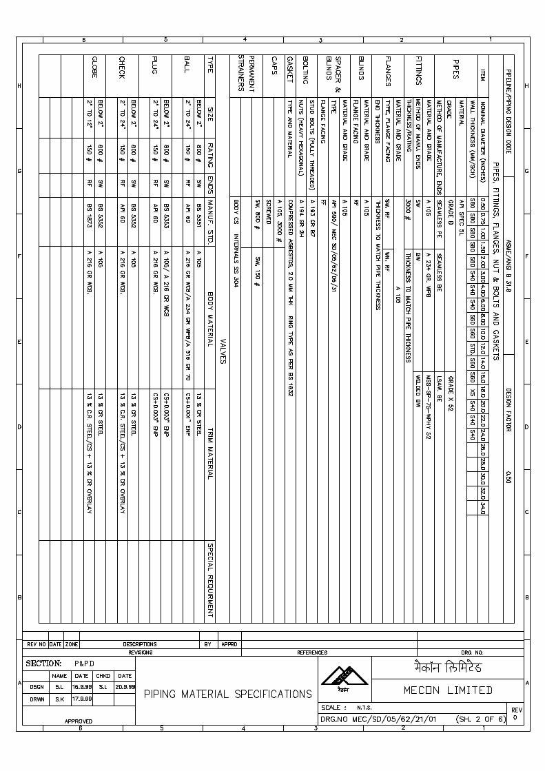
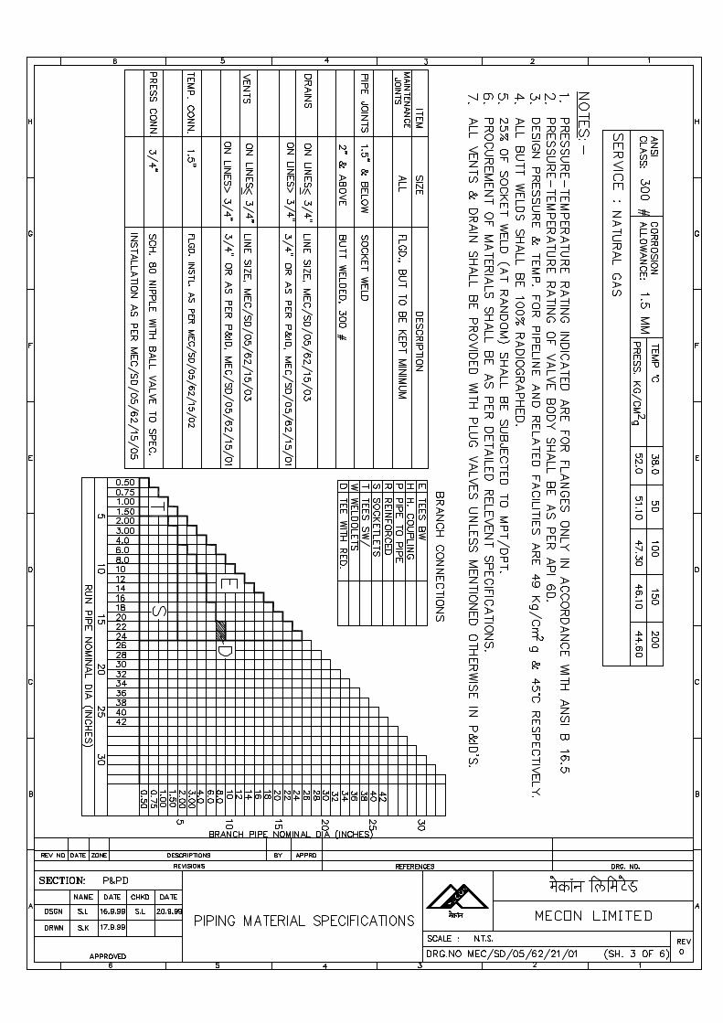
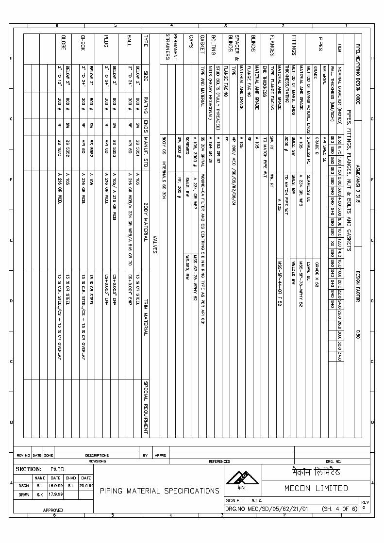

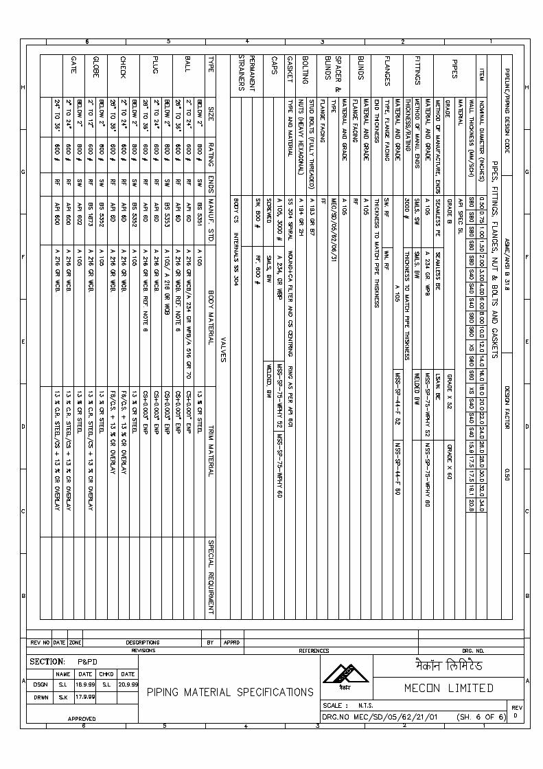
D:\old data\FATEH\Aban Power\TS\Specification for Field Joint Coaitng-13B.doc
GAIL (India) Limited
SPECIFICATIONFOR
FIELD JOINT COATING(ON-SHORE PIPELINE)
SPECIFICATION NO. MEC/S/05/62/13B
(PROCESS & PIPELINE DESIGN SECTION)
MECON LIMITEDDELHI - 110 092
D:\old data\FATEH\Aban Power\TS\Specification for Field Joint Coaitng-13B.doc
CONTENTS
Sl.No. Description Page No.
1.0 SCOPE 1
2.0 REFERENCE DOCUMENTS 1
3.0 MATERIAL AND EQUIPMENT 2 - 6
4.0 APPLICATION PROCEDURE 6 – 10
5.0 INSPECTION & TESTING 10 - 12
6.0 REPAIR 12
7.0 DOCUMENTATION 13
D:\old data\FATEH\Aban Power\TS\Specification for Field Joint Coaitng-13B.doc Page 1 of 11
1.0 SCOPE
This specification covers the minimum requirements of materials, equipment andinstallation of field joint anti-corrosion coating of buried onshore pipelines factorycoated with either three layer polyethylene or fusion bonded epoxy coating, byheatshrink wraparound sleeves or by cold applied tapes conforming to DIN EN 12068 –“Cathodic Protection – External Organic Coatings for the Corrosion Protection ofBuried or Immersed Steel Pipelines used in Conjunction with Cathodic Protection –Tapes and Shrinkable Materials” and the requirements of this specification. Unlessmodified/ replaced by this specification, all requirements of DIN EN 12068 shallremain fully applicable and complied with.
This specification shall be read in conjunction with the conditions of allspecifications and documents included in the Contract between COMPANY andCONTRACTOR. Unless specified otherwise, all section of this specification shallapply to all specifications referred in this specification.
2.0 REFERENCE DOCUMENTS
Reference has been made to the latest edition (edition enforce at the time offloating the enquiry) of the following standards, codes and specifications:
a) ASTM D-149 : Standard Test Methods of DielectricBreakdown voltage and Dielectric Strength ofsolid electrical insulating materials atcommercial frequencies.
b) ASTM D-257 : Standard Test Methods for D-C Resistance orconductance of insulating materials.
c) ASTM D-570 : Standard Method of Test for WaterAbsorption of Plastics
d) ISO 8502-3 : Preparation of Steel Stubstrates beforeApplication of Paints and Related Products –
Part-3 –Assessment of Dust on Steel SurfacesPrepared for Painting (Pressure SensitiveTape Method).
e) ISO:8503-1 : Part-1 : Specification and definitions for ISOsurface profile comparator for theassessment of abrasive blast cleanedsurfaces.
f) ISO:8503-4 : Part-4 : Methods for calibration of ISOsurface profile comparator and for the
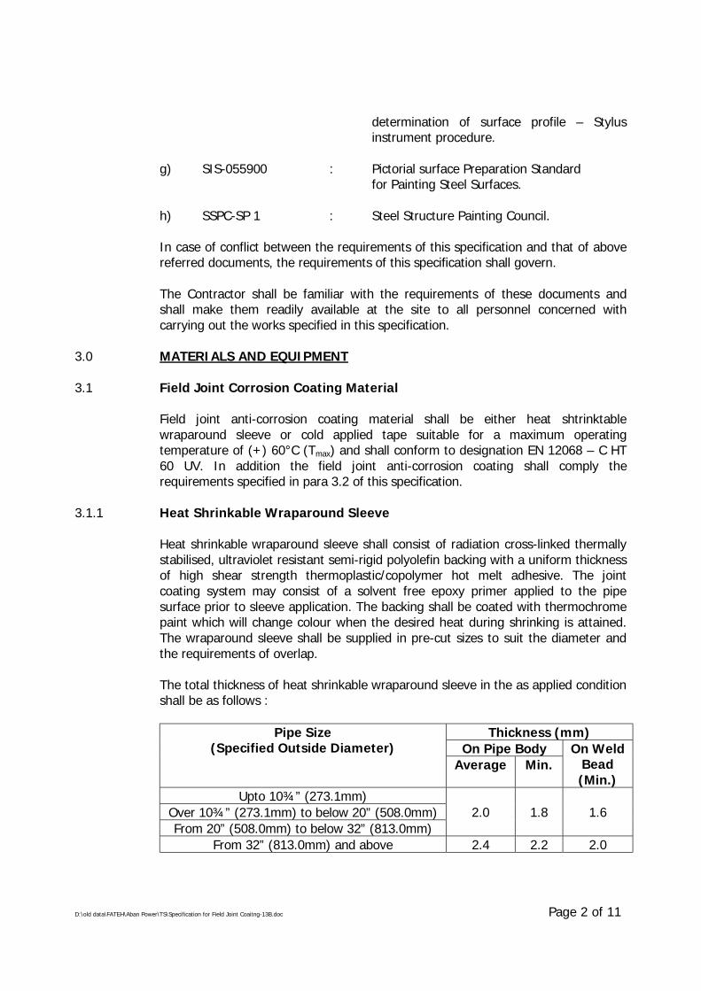
D:\old data\FATEH\Aban Power\TS\Specification for Field Joint Coaitng-13B.doc Page 2 of 11
determination of surface profile – Stylusinstrument procedure.
g) SIS-055900 : Pictorial surface Preparation Standardfor Painting Steel Surfaces.
h) SSPC-SP 1 : Steel Structure Painting Council.
In case of conflict between the requirements of this specification and that of abovereferred documents, the requirements of this specification shall govern.
The Contractor shall be familiar with the requirements of these documents andshall make them readily available at the site to all personnel concerned withcarrying out the works specified in this specification.
3.0 MATERIALS AND EQUIPMENT
3.1 Field Joint Corrosion Coating Material
Field joint anti-corrosion coating material shall be either heat shtrinktablewraparound sleeve or cold applied tape suitable for a maximum operatingtemperature of (+) 60°C (Tmax) and shall conform to designation EN 12068 – C HT60 UV. In addition the field joint anti-corrosion coating shall comply therequirements specified in para 3.2 of this specification.
3.1.1 Heat Shrinkable Wraparound Sleeve
Heat shrinkable wraparound sleeve shall consist of radiation cross-linked thermallystabilised, ultraviolet resistant semi-rigid polyolefin backing with a uniform thicknessof high shear strength thermoplastic/copolymer hot melt adhesive. The jointcoating system may consist of a solvent free epoxy primer applied to the pipesurface prior to sleeve application. The backing shall be coated with thermochromepaint which will change colour when the desired heat during shrinking is attained.The wraparound sleeve shall be supplied in pre-cut sizes to suit the diameter andthe requirements of overlap.
The total thickness of heat shrinkable wraparound sleeve in the as applied conditionshall be as follows :
Thickness (mm)On Pipe Body
Pipe Size(Specified Outside Diameter)
Average Min.On Weld
Bead(Min.)
Upto 10¾” (273.1mm)Over 10¾” (273.1mm) to below 20” (508.0mm)From 20” (508.0mm) to below 32” (813.0mm)
2.0 1.8 1.6
From 32” (813.0mm) and above 2.4 2.2 2.0
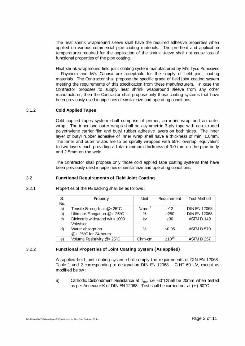
D:\old data\FATEH\Aban Power\TS\Specification for Field Joint Coaitng-13B.doc Page 3 of 11
The heat shrink wraparound sleeve shall have the required adhesive properties whenapplied on various commercial pipe-coating materials. The pre-heat and applicationtemperatures required for the application of the shrink sleeve shall not cause loss offunctional properties of the pipe coating.
Heat shrink wraparound field joint coating system manufactured by M/s Tyco Adhesives– Raychem and M/s Canusa are acceptable for the supply of field joint coatingmaterials. The Contractor shall propose the specific grade of field joint coating systemmeeting the requirements of this specification from these manufacturers. In case theContractor proposes to supply heat shrink wraparound sleeve from any othermanufacturer, then the Contractor shall propose only those coating systems that havebeen previously used in pipelines of similar size and operating conditions.
3.1.2 Cold Applied Tapes
Cold applied tapes system shall comprise of primer, an inner wrap and an outerwrap. The inner and outer wraps shall be asymmetric 3-ply tape with co-extrudedpolyethylene carrier film and butyl rubber adhesive layers on both sides. The innerlayer of butyl rubber adhesive of inner wrap shall have a thickness of min. 1.0mm.The inner and outer wraps are to be spirally wrapped with 55% overlap, equivalentto two layers each providing a total minimum thickness of 3.0 mm on the pipe bodyand 2.5mm on the weld.
The Contractor shall propose only those cold applied tape coating systems that havebeen previously used in pipelines of similar size and operating conditions.
3.2 Functional Requirements of Field Joint Coating
3.2.1 Properties of the PE backing shall be as follows :
Sl.No.
Property Unit Requirement Test Method
a) Tensile Strength at @+25°C N/mm2 ≥12 DIN EN 12068b) Ultimate Elongation @+ 25°C % ≥250 DIN EN 12068c) Dielectric withstand with 1000
Volts/seckv ≥30 ASTM D 149
d) Water absorption@+ 25°C for 24 hours
% ≤0.05 ASTM D 570
e) Volume Resistivity @+25°C Ohm-cm ≥1015 ASTM D 257
3.2.2 Functional Properties of Joint Coating System (As applied)
As applied field joint coating system shall comply the requirements of DIN EN 12068.Table 1 and 2 corresponding to designation DIN EN 12068 – C HT 60 UV, except asmodified below :
a) Cathodic Disbondment Resistance at Tmax i.e. 60°Cshall be 20mm when testedas per Annexure K of DIN EN 12068. Test shall be carried out at (+) 60°C.
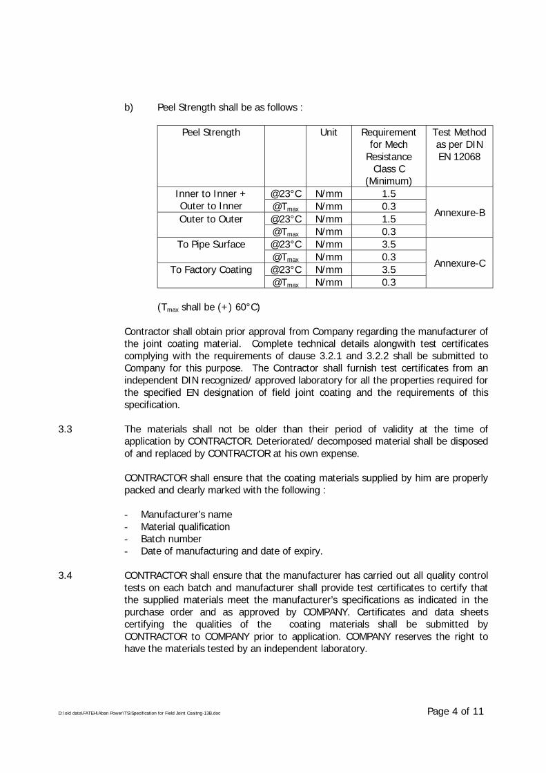
D:\old data\FATEH\Aban Power\TS\Specification for Field Joint Coaitng-13B.doc Page 4 of 11
b) Peel Strength shall be as follows :
Peel Strength Unit Requirementfor Mech
ResistanceClass C
(Minimum)
Test Methodas per DINEN 12068
@23°C N/mm 1.5Inner to Inner +Outer to Inner @Tmax N/mm 0.3
@23°C N/mm 1.5Outer to Outer@Tmax N/mm 0.3
Annexure-B
@23°C N/mm 3.5To Pipe Surface@Tmax N/mm 0.3@23°C N/mm 3.5To Factory Coating@Tmax N/mm 0.3
Annexure-C
(Tmax shall be (+) 60°C)
Contractor shall obtain prior approval from Company regarding the manufacturer ofthe joint coating material. Complete technical details alongwith test certificatescomplying with the requirements of clause 3.2.1 and 3.2.2 shall be submitted toCompany for this purpose. The Contractor shall furnish test certificates from anindependent DIN recognized/ approved laboratory for all the properties required forthe specified EN designation of field joint coating and the requirements of thisspecification.
3.3 The materials shall not be older than their period of validity at the time ofapplication by CONTRACTOR. Deteriorated/ decomposed material shall be disposedof and replaced by CONTRACTOR at his own expense.
CONTRACTOR shall ensure that the coating materials supplied by him are properlypacked and clearly marked with the following :
- Manufacturer’s name- Material qualification- Batch number- Date of manufacturing and date of expiry.
3.4 CONTRACTOR shall ensure that the manufacturer has carried out all quality controltests on each batch and manufacturer shall provide test certificates to certify thatthe supplied materials meet the manufacturer’s specifications as indicated in thepurchase order and as approved by COMPANY. Certificates and data sheetscertifying the qualities of the coating materials shall be submitted byCONTRACTOR to COMPANY prior to application. COMPANY reserves the right tohave the materials tested by an independent laboratory.
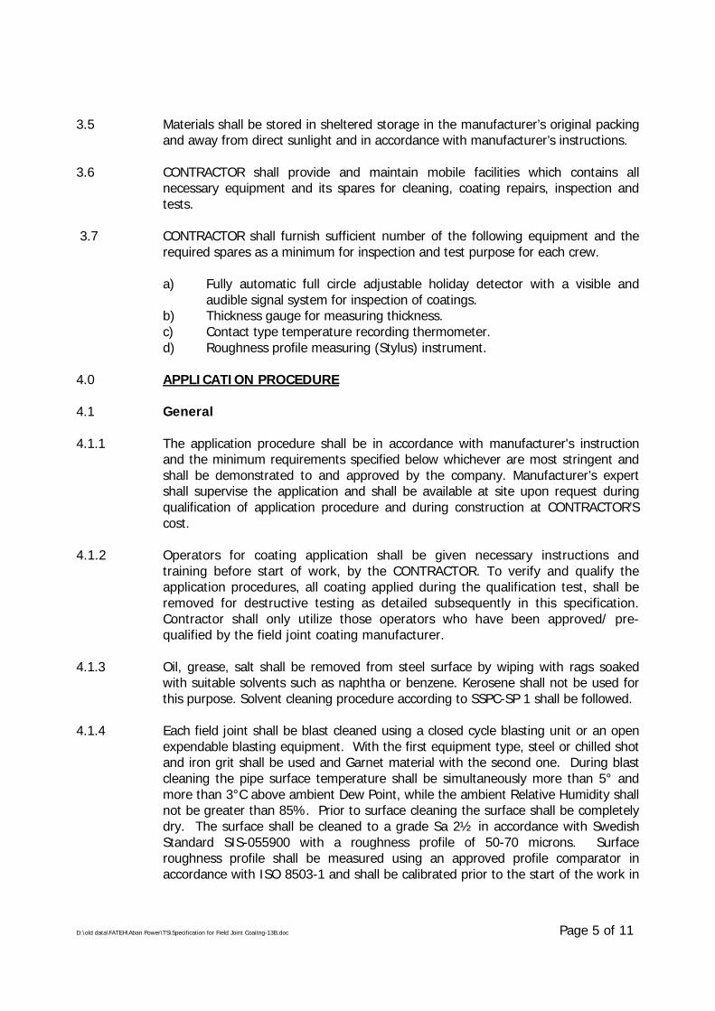
D:\old data\FATEH\Aban Power\TS\Specification for Field Joint Coaitng-13B.doc Page 5 of 11
3.5 Materials shall be stored in sheltered storage in the manufacturer’s original packingand away from direct sunlight and in accordance with manufacturer’s instructions.
3.6 CONTRACTOR shall provide and maintain mobile facilities which contains allnecessary equipment and its spares for cleaning, coating repairs, inspection andtests.
3.7 CONTRACTOR shall furnish sufficient number of the following equipment and therequired spares as a minimum for inspection and test purpose for each crew.
a) Fully automatic full circle adjustable holiday detector with a visible andaudible signal system for inspection of coatings.
b) Thickness gauge for measuring thickness.c) Contact type temperature recording thermometer.d) Roughness profile measuring (Stylus) instrument.
4.0 APPLICATION PROCEDURE
4.1 General
4.1.1 The application procedure shall be in accordance with manufacturer's instructionand the minimum requirements specified below whichever are most stringent andshall be demonstrated to and approved by the company. Manufacturer’s expertshall supervise the application and shall be available at site upon request duringqualification of application procedure and during construction at CONTRACTOR’Scost.
4.1.2 Operators for coating application shall be given necessary instructions andtraining before start of work, by the CONTRACTOR. To verify and qualify theapplication procedures, all coating applied during the qualification test, shall beremoved for destructive testing as detailed subsequently in this specification.Contractor shall only utilize those operators who have been approved/ pre-qualified by the field joint coating manufacturer.
4.1.3 Oil, grease, salt shall be removed from steel surface by wiping with rags soakedwith suitable solvents such as naphtha or benzene. Kerosene shall not be used forthis purpose. Solvent cleaning procedure according to SSPC-SP 1 shall be followed.
4.1.4 Each field joint shall be blast cleaned using a closed cycle blasting unit or an openexpendable blasting equipment. With the first equipment type, steel or chilled shotand iron grit shall be used and Garnet material with the second one. During blastcleaning the pipe surface temperature shall be simultaneously more than 5° andmore than 3°C above ambient Dew Point, while the ambient Relative Humidity shallnot be greater than 85%. Prior to surface cleaning the surface shall be completelydry. The surface shall be cleaned to a grade Sa 2½ in accordance with SwedishStandard SIS-055900 with a roughness profile of 50-70 microns. Surfaceroughness profile shall be measured using an approved profile comparator inaccordance with ISO 8503-1 and shall be calibrated prior to the start of the work in
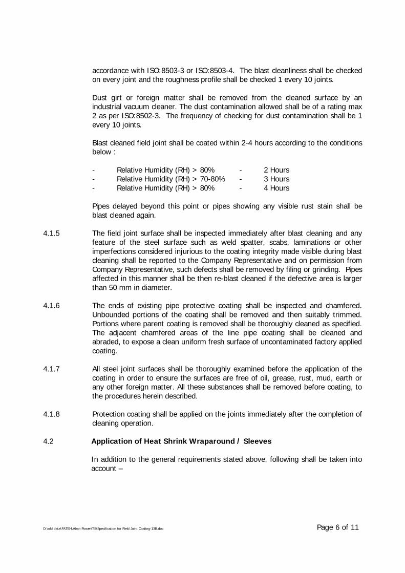
D:\old data\FATEH\Aban Power\TS\Specification for Field Joint Coaitng-13B.doc Page 6 of 11
accordance with ISO:8503-3 or ISO:8503-4. The blast cleanliness shall be checkedon every joint and the roughness profile shall be checked 1 every 10 joints.
Dust girt or foreign matter shall be removed from the cleaned surface by anindustrial vacuum cleaner. The dust contamination allowed shall be of a rating max2 as per ISO:8502-3. The frequency of checking for dust contamination shall be 1every 10 joints.
Blast cleaned field joint shall be coated within 2-4 hours according to the conditionsbelow :
- Relative Humidity (RH) > 80% - 2 Hours- Relative Humidity (RH) > 70-80% - 3 Hours- Relative Humidity (RH) > 80% - 4 Hours
Pipes delayed beyond this point or pipes showing any visible rust stain shall beblast cleaned again.
4.1.5 The field joint surface shall be inspected immediately after blast cleaning and anyfeature of the steel surface such as weld spatter, scabs, laminations or otherimperfections considered injurious to the coating integrity made visible during blastcleaning shall be reported to the Company Representative and on permission fromCompany Representative, such defects shall be removed by filing or grinding. Pipesaffected in this manner shall be then re-blast cleaned if the defective area is largerthan 50 mm in diameter.
4.1.6 The ends of existing pipe protective coating shall be inspected and chamfered.Unbounded portions of the coating shall be removed and then suitably trimmed.Portions where parent coating is removed shall be thoroughly cleaned as specified.The adjacent chamfered areas of the line pipe coating shall be cleaned andabraded, to expose a clean uniform fresh surface of uncontaminated factory appliedcoating.
4.1.7 All steel joint surfaces shall be thoroughly examined before the application of thecoating in order to ensure the surfaces are free of oil, grease, rust, mud, earth orany other foreign matter. All these substances shall be removed before coating, tothe procedures herein described.
4.1.8 Protection coating shall be applied on the joints immediately after the completion ofcleaning operation.
4.2 Application of Heat Shrink Wraparound / Sleeves
In addition to the general requirements stated above, following shall be taken intoaccount –
D:\old data\FATEH\Aban Power\TS\Specification for Field Joint Coaitng-13B.doc Page 7 of 11
4.2.1 The wrap around sleeve shall be of a size such that a minimum overlap of 50mmbefore applying is ensured (after shrinking) on both sides of the yard appliedcorrosion coating of pipes.
In the cases where carrier pipe is installed by direct boring/ jacking, the overlap onthe mill coating for the leading edges of the joints shall be minimum 200mm. Whenthis extra overlap is achieved by providing an additional patch of heat shrink tape/wraparound, it shall be applied in such a manner that the square edge of the patchon the joint coating is in the direction opposite to the direction of boring/ jacking.
4.2.2 Before centering the wraparound sleeve, the bare steel surface shall be preheatedwith torch moved back and forth over the surface or by induction heating. Theminimum preheat temperature shall be as recommended by manufacturer and shallbe checked by means of contact type temperature recording thermometer.Temperature indicating crayons shall not be used Pre-heat temperature shall bechecked on every joint. Care shall be taken to ensure that the entire circumferenceof the pipe is heated evenly. Temperature measuring instruments shall becalibrated immediately before the start of the works and thereafter at intervalsrecommended by the manufacturer of the instrument.
4.2.3 Upon pre-heating the pipe surface shall be applied with two pack epoxy primer ofwet film thickness 100 microns or as per manufacturer’s recommendationwhichever is higher, to cover the exposed bare metal of the welded field joint and10mm min. onto the adjacent pipe coating if recommended by the manufacturer.The wet film thickness of the primer shall be checked or every joint with a wet filmthickness gauge prior to installation of sleeve. Thickness gauge shall be calibratedonce per shift.
4.2.4 Immediately after application of epoxy primer, the wraparound sleeve shall beentirely wrapped around the pipe within the stipulated time recommended by themanufacturer. Sleeve shall be positioned such that the closure patch is located toone side of the pipe in 10 or 2 O’clock position, with the edge of the undergoinglayer facing upward and an overlap of min. 50mm. Gently heat by appropriatetorch the backing and the adhesive of the closure and press it firmly into place.
4.2.5 A heat shrinking procedure shall be applied to shrink the sleeve in such a mannerto start shrinkage of the sleeve beginning from the center of the sleeve and heatcircumferentially around the pipe. Continue heating from the center towards oneend of the sleeve until recovery is completed. In a similar manner, heat andshrink the remaining side. Shrinking has been completed when the adhesivebegins to ooze at the sleeve edges all around the circumference.
The complete shrinking of the entire sleeve shall be obtained without undueheating of existing pipe coating and providing due bonding between pipe, sleeveand pipe coating. The installed sleeve shall not be disturbed until the adhesive hassolidified.
D:\old data\FATEH\Aban Power\TS\Specification for Field Joint Coaitng-13B.doc Page 8 of 11
4.3 Application Procedure for Corrosion Protection Tapes
4.3.1 Cold applied joint protection tapes shall be of the type which can be applied byspirally wrapping on the pipe.
4.3.2 Immediately after the completion of surface preparation the approved primer ofwet film thickness 100 microns or as per manufacturer’s recommendationwhichever is higher to cover the exposed bare metal of the welded field joint and10mm min. onto the adjacent pipe coating if recommended by the manufacturer.Any dirt on the primed surface shall be removed. If the primer is damaged, thedamaged area shall be cleaned and re-primed.
4.3.3 Approximately 100mm of tape interleaving paper shall be peeled back and tapeshall be applied with the adhesive side to the pipe. Whilst continuously removingthe interleaving paper, the tape shall be spirally applied to provide a minimum of55% overlap. Sufficient tension shall be applied to ensure good conformity,avoiding air pockets and also continuously smooth out as the wrapping proceeds.The wrapping shall start and finish to give a minimum of 50mm overlap on to theadjoining yard applied coating. Outer wrap shall be applied in similar method.
4.4 Pre-Qualification of Field Joint Coating System
The field joint coating system materials and the procedures proposed by theContractor shall be pre-qualified during the sleeve installation start-up phase. Fivejoints (5) shall be coated with the requirements of this specification and theninspected and tested in accordance with the requirements of this specification withrespect to the following :
- Surface preparation cleanliness, roughness profile and dust contamination- Pre-heat temperature (as applicable)- Primer thickness- As applied coating thickness- Holiday detection- Peel test at (+) 23°C & (+) 60°C on pipe surface & factory applied coating
and at over laps (as applicable). If required to achieve the temperature of(+) 60°C, suitable thermal blanket may be used.
- Visual appearance and void after installation on the body, area adjoining theweld and area adjoining the factory applied coating. (To establish voidsadjoining the weld and factory coating a strip of 50mm wide and 200mmlong shall be stripped and examined).
Company Representative shall witness the tests and inspection. Regular applicationof field joint coating shall commence only upon successful completion of the pre-qualification testing.
After successful completion of the pre-qualification testing as above, the entire fieldjoint coating shall be removed, the pipe surface re-blasted and field joint coatingre-applied as per the requirements of this specification.
D:\old data\FATEH\Aban Power\TS\Specification for Field Joint Coaitng-13B.doc Page 9 of 11
5.0 INSPECTION & TESTING
5.1 Visual Inspection
Visual inspection of the as applied coating shall be carried out on every joint, forthe following :
- Mastic extrusion on either ends of the sleeve shall be examined.
- There shall be no sign of punctures or pinholes or bend failure. The externalappearance of the sleeve shall be smooth, free of dimples, air entrapmentor void formation. All sleeves shall be tested for the presence of voids byknocking on the sleeves. A hollow sound compared to the remainder of thesleeve may indicate the presence of voids under the sleeve. Such sleeveshall be tested for adhesion at the discretion of the CompanyRepresentative.
- Weld bead profile shall be visible through the sleeve.
- Visual indicator provided on the backing and the closure patch showingdesired heat is achieved.
5.2 Holiday Inspection
The holiday detector used shall be checked and calibrated daily with an accurateDC voltmeter. The detector electrode shall be in direct contact with the surface ofcoating to be inspected.
The entire surface of the joint section shall be inspected by means of a full circleholiday detector approved by COMPANY set to a DC voltage applicable as per therequirements of factory applied mainline coating specification of Company.Inspection of the sleeves shall be conducted only after the joint has cooled below50°C. The holiday detector used shall be checked and calibrated daily with anaccurate DC voltmeter. The detector electrode shall be in direct contact with thesurface of coating to be inspected.
No field joint shall be covered or lowered in the trench until it has been approvedby the COMPANY.
5.3 As-applied Coating Thickness
Coating thickness shall be checked by non-destructed methods for each field joint.Average thickness of the as-applied coating on pipe body shall be established basedon measurement at min. eight locations i.e. four measurement on either sides ofthe girth weld at 3, 6, 9, & 12 O’clock positions. To establish the minimumthickness on the girth weld, four measurement shall be taken on apex on the weldat 3, 6, 9 & 12 O’clock positions. All such measurements shall be recorded.
D:\old data\FATEH\Aban Power\TS\Specification for Field Joint Coaitng-13B.doc Page 10 of 11
Company Representative reserves the right to ask for additional measurement atany location on the field joint coating, whenever doubt arises.
5.4 Peel Strength Testing
5.4.1 One out of every 50 joint coatings or one joint coating out of every day’sproduction whichever is stringent shall be tested to establish the peel strength onsteel and factory applied coating. Contractor shall carry out such testing in thepresence of Company Representative.
5.4.2 From each test sleeve selected as above, one or more strips of size 25mm x200mm shall be cut perpendicular to the pipe axis and slowly peeled off.
The required peel strength shall meet the requirements of this specification asapplicable for (+) 23°C or (+) 60°C whichever is feasible. This test shall beconducted between wrapping & metal and mill coating & between layers at overlapwith joint coating (wherever applicable). After removal of strip, the bulk ofadhesive shall remain adhered to the pipe showing no bare metal, otherwise, testshall be considered failed. The adhesive layer that remains on the pipe surfaceshall generally be free of voids resulting from air or gas inclusion. In case the peelstrength test at a different temperature than that specified in warranted due to theambient site conditions, then the peel strength shall comply the recommendation ofthe manufacturer. Manufacturer shall be asked to furnish peel strength valuescorresponding to various expected temperatures, prior to start of the works.
5.4.3 If the sleeve does not meet the requirements of clause 5.4.2 the adjacent twosleeves shall also be tested. If the adjacent two sleeves are acceptable the test rateshall be increased to one sleeve every twenty five until Company’s Representativeis satisfied. The test rate can then be reduced as per clause 5.4.1. If either orboth of the adjacent two sleeves do not meet the requirements of clause 5.4.2, thefield joint shall be stopped.
5.4.4 Company Representative reserve the right of 100% removal of sleeves if he is notconvinced that the requirements of clause 5.4.2 are achieved.
6.0 REPAIRS
6.1 If a field joint is detected to be unacceptable after testing as per section 5.0 of thisspecification the Contractor shall, at his own cost :
- Determine the cause of the faulty results of the field coating.
- Mobilise the expert of manufacturer, if required.
- Test to be complete satisfaction of the COMPANY, already completed fieldcoatings.
D:\old data\FATEH\Aban Power\TS\Specification for Field Joint Coaitng-13B.doc Page 11 of 11
- Stop field coating until remedial measures are taken against the causes of suchfaults, to the entire satisfaction of the Company.
6.2 CONTRACTOR shall replace all joint found or expected to be unacceptable as persection 5.0 of this specification.
6.3 CONTRACTOR shall, at his own cost repair all areas where the coating has beenremoved for testing by COMPANY.
6.4 After the coating work on welded joints, fittings and repairs to the coating havebeen completed the coating as a whole shall be tested with a spark-tester beforelowering or jacking the pipeline.
6.5 COMPANY shall be entitled to check the coating on buried pipelines or parts ofpipelines with equipment such as the "Pearson Meter" and the resistance meter. Ifthe Coating defects are established, the Contractor shall be responsible forexcavations at such points repair the coating, spark testing and back filling theexcavations without extra charge.
7.0 DOCUMENTATION
7.1 Prior to procurement of coating materials, Contractor shall furnish the followinginformation for qualification of the manufacturer and material :
i. Complete information as per clause 5.2, DIN EN 12068 alongwithdescriptive technical catalogues.
ii. Test certificates and results of previously conducted tests, for allproperties listed in clause 3.2 of this specification.
iii. Reference list of previous supplies, in last 5 years, of the similar materialindicating the project details such as diameter, quantity, operatingtemperature, year of supply, project name, contact person and feed backon performance.
Once the Company’s approval has been given, any change in material orManufacturer shall be notified to Company, whose approval in writing of allchanges shall be obtained before the materials are manufactured.
7.2 Prior to shipment of materials from the Manufacturer’s works. Contractor shallfurnish the following documents :
i. Test certificates/ results as per Manufacturer’s Quality Control Procedurefor each batch of materials.
ii. Specific application instructions with pictorial illustrations.iii. Specific storage and handling instructions.
7.3 All documents shall be in English language only.
\\Akjha\work contrac\standard TS for Pipe Line WC (Vol-II) MASTER FOLDER\14 3-layer pe coated line pipe\3-LPE Coating of Linepipes-TS-R2 14.doc
SPECIFICATIONFOR
3-LAYER POLYETHYLENE COATING OF LINEPIPES
SPECIFICATION NO. : MEC/S/05/62/014, Rev-2
MECON LIMITEDDELHI - 110 092
\\Akjha\work contrac\standard TS for Pipe Line WC (Vol-II) MASTER FOLDER\14 3-layer pe coated line pipe\3-LPE Coating of Linepipes-TS-R2 14.doc
C O N T E N T S
1.0 SCOPE
2.0 REFERENCE DOCUMENTS
3.0 PLANT SCALE AND INSTALLATION
4.0 MATERIALS
5.0 FUNCTIONAL REQUIREMENTS AND PROPERTIES OF COATING
6.0 MEASUREMENT AND LOGGING
7.0 COATING PROCEDURE AND QUALIFICATION
8.0 PIPE SURFACE PREPARATION
9.0 COATING APPLICATION
10.0 INSPECTION AND TESTING
11.0 HANDLING, TRANSPORTATION AND STORAGE
12.0 REPAIR OF COATING
13.0 MARKING
14.0 QUALITY ASSURANCE
ANNEXURE-I : COATING SYSTEM/ MATERIAL PRE-QUALIFICATION
\\Akjha\work contrac\standard TS for Pipe Line WC (Vol-II) MASTER FOLDER\14 3-layer pe coated line pipe\3-LPE Coating of Linepipes-TS-R2 14.doc Page 1 of 35
1.0 SCOPE
This specification covers the minimum requirements for supply/ arrangement of allmaterials, plant, equipment, plant sites, consumables, utilities and applicationincluding all labour, supervision, inspection and tests etc. for application of externalanti-corrosion coating of pipes by using 3 Layer Side Extruded Polyethylene Coatingconforming to DIN-30670, 1991, `Polyethylene Coating of Steel Pipes and Fittings'and the requirements of this specification.
2.0 REFERENCE DOCUMENTS
Reference has also been made to the latest edition of the following standards,codes and specifications. The edition enforce at the time of floating the enquiryshall be termed as latest edition.
a. ASTM D-149 : Standard Test Methods of DielectricBreakdown voltage and Dielectric strength ofsolid electrical insulating materials atcommercial frequencies.
b. ASTM D-257 : Standard Test Methods for D-C Resistance orconductance of insulating materials.
c. ASTM D-543 : Standard Method of Test for Ressistance ofPlastics to Chemical Reagents.
d. ASTM D-570 : Standard Method of Test for WaterAbsorption of Plastics.
e. ASTM D-638 : Standard Test Method for TensileProperties of Plastics.
f. ASTM D-792 : Standard Test Method of Specific Gravity andDensity of Plastics by Displacement.
g. ASTM D-1238 : Test Method for Low Rate of Thermoplasticsby Extrusion.
h. ASTM D-1525 : Test Method for Vicat Softening Temperatureof Plastics
i. ASTM D-1603 : Test Method for Carbon Black in OlefinPlastics
j. ASTM D-1693 : Test Method for Environmental StressCracking of Ethylene Plastics
\\Akjha\work contrac\standard TS for Pipe Line WC (Vol-II) MASTER FOLDER\14 3-layer pe coated line pipe\3-LPE Coating of Linepipes-TS-R2 14.doc Page 2 of 35
k. ASTM D-2240 : Test Method for Rubber Property –Durometer Hardness
l. ASTM D-3895 : Test Method for Oxidative – Induction Timeof Polyolefins by Differential ScanningCalorimetry
m. ASTM G-42 : Tentative Methods for Cathodic disbonding ofPipeline Coatings Subjected to Elevated orCyclic Temperatures.
n. API RP 5L1 : Recommended Practice for RailroadTransportation of Linepipe.
o. API RP 5LW : Transportation of Line Pipe on barges andmarine vessels
p. DIN EN 10204 : Metallic Products – Types of InspectionDocuments
q. DIN 53735 : Testing of Plastics : Determination of MeltIndex of Thermoplastics.
r. ISO 8502-3 : Preparation of Steel Stubstrates beforeApplication of Paints and Related Products –Part-3 – Assessment of Dust on SteelSurfaces Prepared for Painting (PressureSensitive Tape Method)
s. ISO 9002 : Quality Systems : Specification of Productionand Installation
t. ISO 11124 : Preparation of Steel Substrates BeforeApplication of Paints and Related Products
u. SIS 055900 : Preparation of Steel Substrates beforeApplication of Paints and Related Products –Visual Assessment of Surface Cleanliness.
v. APL 5L : Specification for Line Pipe
w. ASME B 31.8 : Gas Transmission and DistributionPiping Systems
x. ASME B 31.4 : Liquid Transportation systems forHydrocarbons, Liquid petroleum GasAnhydrous ammonia, and Alcohols
\\Akjha\work contrac\standard TS for Pipe Line WC (Vol-II) MASTER FOLDER\14 3-layer pe coated line pipe\3-LPE Coating of Linepipes-TS-R2 14.doc Page 3 of 35
y. CSA Z245.20-98 : External Fusion Bond Epoxy Coating forSteel Pipe
The CONTRACTOR shall be familiar with the requirements of these documentsand shall make them readily available at the coating plant to all personsconcerned with carrying out the works specified in this specification.
3.0 PLANT SCALE AND INSTALLATION
3.1 CONTRACTOR shall size coating plant(s) after evaluating the scale of work and thetime schedule required for the works. Coating plant(s), shall be installed into a yardwhose geometry and dimensions are such as to allow the execution of a continuouswork schedule. For this purpose the CONTRACTOR shall ensure non stop workexecution owing to prohibitive adverse weather conditions and when requiredCONTRACTOR shall install requisite equipment and plant in roofed and adequatelyweather protected areas.
3.2 Plant equipment, machinery and other facilities shall be in first class operatingcondition to atleast meet the job requirements of quality and production. Worn outand improvised plants are not acceptable.
3.3 CONTRACTOR shall, at his own responsibility and cost, provide and prepare allnecessary area for the storage of bare and coated pipe and all other materials, forcoating yard, stock-piling and other temporary installation. For each area,CONTRACTOR shall provide to stipulate servitude agreements as required with therelevant Authorities, and, on work completion, to clean, restore and pay servitudeand claims for damages, as applicable.
3.4 CONTRACTOR shall at its own responsibility and cost, provide for water and powersupply and other utilities and consumables and obtain authorisation regardingaccess roads and other permits required for the execution of works conforming toall the requirements of the governing authorities.
3.5 CONTRACTOR shall at its own expense provide a fully equipped laboratory and testfacilities with adequate inventory to carry out tests required for the procedurequalification and during regular production. Outside testing for qualification andregular production is not acceptable to COMPANY.
3.6 The CONTRACTOR shall be fully responsible for adherence to all statutoryregulations applicable for handling and disposal of the hazardous chemicals duringthe coating works.
3.7 The CONTRACTOR shall be responsible for obtaining all statutory approvals/clearances from relevant Authorities including Pollution Control Board, as applicablefor the coating plant(s).
\\Akjha\work contrac\standard TS for Pipe Line WC (Vol-II) MASTER FOLDER\14 3-layer pe coated line pipe\3-LPE Coating of Linepipes-TS-R2 14.doc Page 4 of 35
4.0 MATERIALS
4.1 The three layer coating system shall comprise of a powder epoxy primer,polythylene adhesive and a polyethylene top coat. Coating materials shall besuitable for the service conditions and the pipe sizes involved. The coating materialsi.e. epoxy powder, adhesive and polyethylene compound shall have provencompatibility. The coating system and materials shall be pre-qualified and approvalCOMPANY in accordance with provision Annexure-I of this specification.CONTRACTOR shall obtain prior approval from COMPANY for the coating systemand coating of all materials.
4.2 The coating materials Manufacturer shall carry out tests for all properties specifiedin para 5.3.1 and 5.3.2 for each batch of epoxy, adhesive and polyethylenecompound. In addition, the Manufacturer shall also furnish Infra-red Scan for eachbatch of epoxy powder. The coating materials manufacturer shall issue testcertificates as per DIN EN 10204, 3.1B for each batch of materials supplied toCONTRACTOR and the same shall be submitted to COMPANY for approval prior totheir use.
4.3 In addition to Manufacturer’s certificate, the CONTRACTOR shall draw samplesfrom each batch of epoxy, adhesive and polyethylene in the presence ofCOMPANY Representative and test for the following properties at the coatingyard at least one week prior to its use, to establish compliance with theManufacturer’s certificates.
a) Epoxy Powder
i. Gel Timeii. Cure Timeiii. Moisture Contentiv. Thermal Characteristics (Tgl, Tg2, ∆H)
b) Adhesive
i. Specific Gravityii. Melt Flow Rateiii. Vicat Softening Point
c) Polyethylene
i. Melt Flow Rateii. Specific Gravityiii. Vicat Softening Pointiv. Moisture Contentv. Oxidative Induction Time
In case of failure of any of the above tests in a batch, that batch of material shallbe tested for all other tests required as per para 5.3.1 and 5.3.2 including the tests
\\Akjha\work contrac\standard TS for Pipe Line WC (Vol-II) MASTER FOLDER\14 3-layer pe coated line pipe\3-LPE Coating of Linepipes-TS-R2 14.doc Page 5 of 35
which failed. If all tests pass, the batch shall be accepted for coating. If any of thetests fail, entire batch of material shall be rejected and shall not be used for thecoating.
4.4 All materials to be used shall be supplied in sealed, damage free containers andshall be suitably marked and identifiable with the following minimum information:
a. Name of the manufacturerb. Type of materialc. Batch Numberd. Place and Date of Manufacturee. Shelf Life/ Expiry Date (if applicable)f. Quantity
All materials noted to be without above identification shall be deemed/ suspect andshall be rejected by COMPANY. Such materials shall not be used for coating andshall be removed from site and replaced by CONTRACTOR at its expense.
4.6 CONTRACTOR shall ensure that all coating materials properly stored in accordancewith the Manufacturer’s recommendation at all times, to prevent damage anddeterioration in quality prior to use.
4.7 CONTRACTOR shall be required to use all materials on a date received rotationbasis, i.e. first in-first used basis.
5.0 FUNCTIONAL REQUIREMENTS AND PROPERTIES COATING
5.1 The coating must be able to withstand a maximum in service operatingtemperature of +65°C and shall conform to `S’ Type of coating as per DIN 30670.In addition, in open storage the coating must be able to withstand a temperature ofatleast +80°C, without impairing its serviceability and properties specified.
5.2 The top coat polyethylene used shall be black readymade compound, fully stabilizedagainst influence of ultraviolet radiation (.e. sunlight), oxygen in air and heat (dueto environmental temperature as specified above). No appreciable changes shalloccur during exposure to such environments up to at least a period of 6000 hours.The CONTRACTOR shall submit certificate from Manufacturer in this regard.
5.3 Properties
Properties of coating system and coating material shall comply the requirementsindicated in subsequent paragraph. In case the coating/ material properties aretested as per test methods/ standards other than specified herein below, the samemay be accepted provided the test procedures and test conditions are same ormore stringent than the specified.
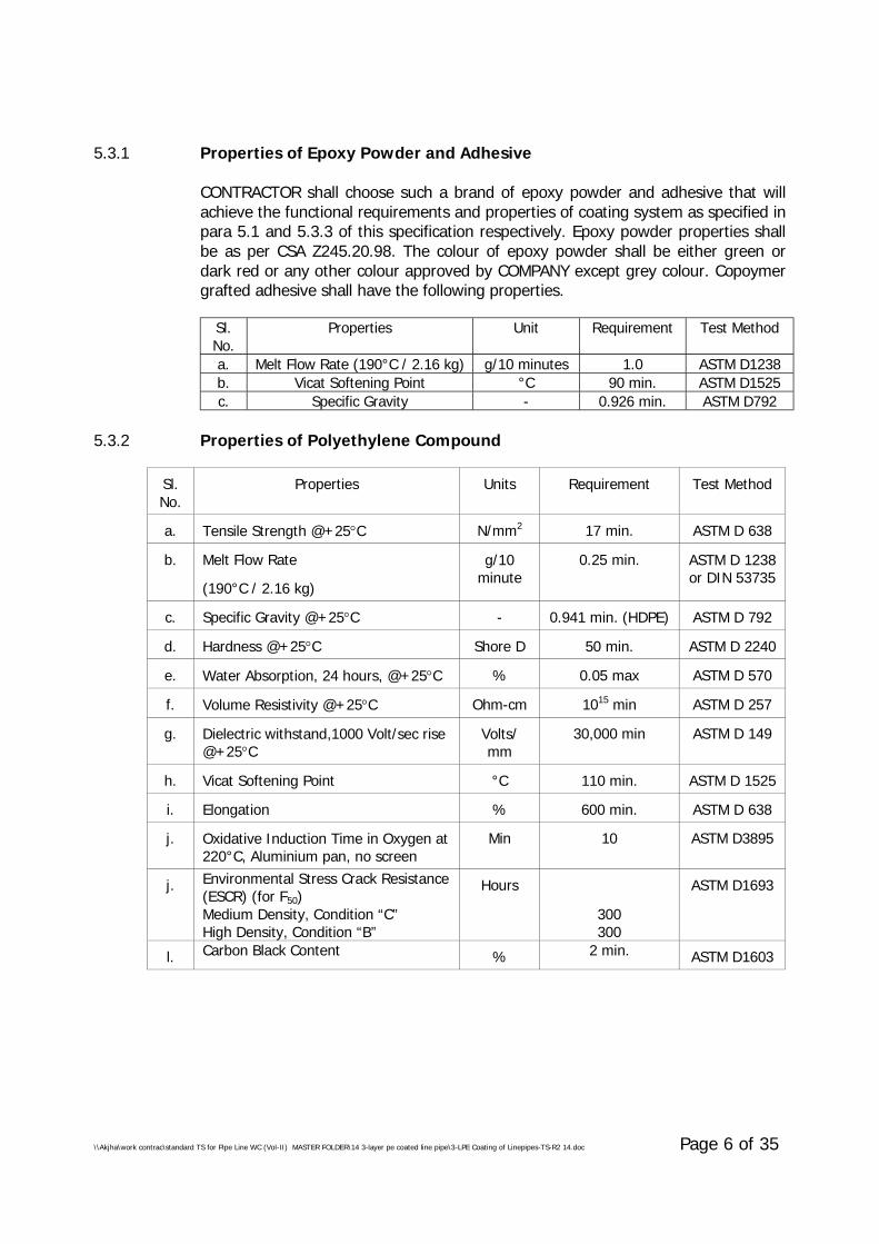
\\Akjha\work contrac\standard TS for Pipe Line WC (Vol-II) MASTER FOLDER\14 3-layer pe coated line pipe\3-LPE Coating of Linepipes-TS-R2 14.doc Page 6 of 35
5.3.1 Properties of Epoxy Powder and Adhesive
CONTRACTOR shall choose such a brand of epoxy powder and adhesive that willachieve the functional requirements and properties of coating system as specified inpara 5.1 and 5.3.3 of this specification respectively. Epoxy powder properties shallbe as per CSA Z245.20.98. The colour of epoxy powder shall be either green ordark red or any other colour approved by COMPANY except grey colour. Copoymergrafted adhesive shall have the following properties.
Sl.No.
Properties Unit Requirement Test Method
a. Melt Flow Rate (190°C / 2.16 kg) g/10 minutes 1.0 ASTM D1238b. Vicat Softening Point °C 90 min. ASTM D1525c. Specific Gravity - 0.926 min. ASTM D792
5.3.2 Properties of Polyethylene Compound
Sl.No.
Properties Units Requirement Test Method
a. Tensile Strength @+25°C N/mm2 17 min. ASTM D 638
b. Melt Flow Rate
(190°C / 2.16 kg)
g/10minute
0.25 min. ASTM D 1238or DIN 53735
c. Specific Gravity @+25°C - 0.941 min. (HDPE) ASTM D 792
d. Hardness @+25°C Shore D 50 min. ASTM D 2240
e. Water Absorption, 24 hours, @+25°C % 0.05 max ASTM D 570
f. Volume Resistivity @+25°C Ohm-cm 1015 min ASTM D 257
g. Dielectric withstand,1000 Volt/sec rise@+25°C
Volts/mm
30,000 min ASTM D 149
h. Vicat Softening Point °C 110 min. ASTM D 1525
i. Elongation % 600 min. ASTM D 638
j. Oxidative Induction Time in Oxygen at220°C, Aluminium pan, no screen
Min 10 ASTM D3895
j. Environmental Stress Crack Resistance(ESCR) (for F50)Medium Density, Condition “C”High Density, Condition “B”
Hours
300300
ASTM D1693
l. Carbon Black Content % 2 min. ASTM D1603

\\Akjha\work contrac\standard TS for Pipe Line WC (Vol-II) MASTER FOLDER\14 3-layer pe coated line pipe\3-LPE Coating of Linepipes-TS-R2 14.doc Page 7 of 35
5.3.3 Properties of Coating System
Sl.No.
Properties Unit Requirement Test Method
a. Bond Strength (using Type 2 TestAssembly i.e. Dynamometer)@ 20±5°C@ 60±5°C
Kg/cm
8.0 min5.0 min.
DIN 30670
b. Impact Strength (min. of 30 impacts onbody along the length. No breakdownallowed when tested at 25 kV)
Joules per mmof coatingthickness
7 minDIN 30670
c. Indentation Hardness
@ 23±2°C
@ 70±2°C
mm
0.2 max
0.3 max
DIN 30670
d. Elongation at Failure % 300 min. DIN 30670
e. Coating Resistivity (*) Ohm-m2 108 min. DIN 30670
f. Heat Ageing (*) - Melt flow rate shallnot deviate by more
than 35% oforiginal value
DIN 30670
g. Light Ageing (*) - Melt flow rate shallnot deviate by more
than 35% oforiginal value
DIN 30670
h. Cathodic Disbondment
@+65°C after 30 days
@+65°C after 48 hrs
mm radius ofdisbondment
(**)15 max.
7 max.
ASTM G42
i. Degree of Cure of Epoxy
Percentage Cure, ∆H
∆Tg
%
°C
95
+3/ -2
CSAZ245.20-
98(*)
(*) Test carried out in an independent laboratory of national/ internationalrecognition on PE top coat is also acceptable.
(**) Disbondment shall be equivalent circle radius of total unsealed area as perASTM G42.
(***) Temperature to which the test specimens are to be heated during cyclicheating shall however be as per the recommendations of epoxy powdermanufacturer.
6.0 MEASUREMENT AND LOGGING
CONTRACTOR shall maintain records in computer using MS ACCESS databaseSoftware containing all the relevant data of individual pipe and pipe coatingincluding heat number, diameter, length, wall thickness, defects, pipe number,batches of materials, materials balance, sampling, testing, damages, repairs,rejects and any other information that COMPANY considers to be relevant andrequired for all incoming bare pipes and COMPANY approved outgoing coated
\\Akjha\work contrac\standard TS for Pipe Line WC (Vol-II) MASTER FOLDER\14 3-layer pe coated line pipe\3-LPE Coating of Linepipes-TS-R2 14.doc Page 8 of 35
pipes as applicable. CONTRACTOR shall submit this information in the form of areport at the agreed intervals. The above data shall also be provided in MSEXCEL/MS ACCESS formant in Compact Disc (CD). CONTRACTOR shall provide aComputer Terminal to COMPANY Representative for monitoring/tracking of theabove. The CONTRACTOR shall also submit the material balance details toCOMPANY for information at the end of shift.
7.0 COATING PROCEDURE AND QUALIFICATION
7.1 Upon the award of the CONTRACT, the CONTRACTOR shall submit within two(2)weeks for COMPANY approval, a detailed report in the form of bound manualoutlining, but not limited to the following:
a. Details of plant(s), locations, layout, capacity and production rate(s).b. Details of the equipment available to carry out the coating works including
surface preparation, epoxy powder application and its recycling system,adhesive & polyethylene extrusion, moisture control facilities available forcoating materials.
c. Details of process control and inspection equipment required for thecoating process such as temperature control, thickness control, holidaytesters, etc.
d. Details of chemicals pre-treatment facilities including process control andinspection equipment for phosphoric acid wash, de-ionised-ionised waterwash and chromate wash.
e. Facilities in the yard for unloading, handling, transport, production,storage, stockpiling, loading of bare and coated pipes and warehouses forstorage of other coating materials.
f Plant Organogram Chart and availability of manpower including coatingspecialist.
g Details of utilities/facilities such as water, power, fuel, access roads andcommunication etc.
After approval has been given by COMPANY, no change in plant set-up shall bemade. However, unavoidable changes shall be executed only after obtainingwritten approval from COMPANY.
7.2 At least four(4) weeks prior to the commencement of production coating, adetailed procedure of CONTRACTOR's methods, material proposed, etc., shall beformulated by CONTRACTOR and submitted for COMPANY's approval in the formof a bound manual. The procedure shall include, but not limited to the followinginformation and proposals:
a. Pipe inspection at the time of bare pipe receipt.b. Steel surface preparation, including preheating, removal of steel defects,
method of pipe cleaning, dust removal, abrasive blast cleaning and surfaceprofile, methods of measurements and consumables.
c. Complete details of chemical pre-treatment viz phosphoric acid wash, de-ionised water wash, and chromate wash including product data sheets,
\\Akjha\work contrac\standard TS for Pipe Line WC (Vol-II) MASTER FOLDER\14 3-layer pe coated line pipe\3-LPE Coating of Linepipes-TS-R2 14.doc Page 9 of 35
health and safety sheets and manufacturer’s recommended applicationprocedure.
d. Pipe heating, temperatures and control prior to epoxy application.e. Complete details of raw materials including current data sheets showing
values for all the properties specified together with quality control andapplication procedure recommendation from manufacturer(s).
f. Application of FBE powder, adhesive and polyethylene, includingcharacteristics, temperature, line speed, application window, curing time,etc.
g. Quenching and cooling, including time and temperature.h. Quality assurance system, Inspection and testing methods and reporting
formats, including instrument and equipment types, makes and uses etc.i. Detailed method of repair of coating defects duly classified depending upon
nature and magnitude of defects and repairs thereof including coatingstripping technique.
j. Details of instrument and equipment calibration methods including relevantstandards and examples of calibration certificates.
k. Complete details and inventory of laboratory and equipment for procedurequalification and regular production.
l. Pipe handling and stock piling procedures.m. Sample of recording and reporting formats, including laboratory reports,
certificates and requirement as per clause 6.0 of this specification.n. Complete details of test certificates for raw materials including test
methods standards used.o. Test certificates from PE compound manufacturer for tests for thermal
aging coating resistivity and aging under exposure to light. These testcertificates shall not be older than three years.
p. Health, safety and environment plans.q. Storage details of coating materials and chemicals.r. Continuous temperature monitoring at various stages of coating.
Procedure Qualification Tests (PQT) shall be carried out only after obtainingwritten approval of the above procedure from COMPANY. No change in theprocedure shall be made after approval has been given by the COMPANY.However, unavoidable changes shall be executed only after obtaining writtenapproval from COMPANY.
7.3 Prior to start of production, CONTRACTOR shall, at his expense, carry out acoating procedure qualification trial for each pipe diameter, and for each plant,to prove that his plant, materials, and coating procedures result in a quality ofend product conforming to the properties stated in clause 5.3, relevantstandards, specifications and material manufacturer’s recommendations.CONTRACTOR shall give seven(7) working days notice to witness procedures andtests.
A batch representing a normal production run, typically 15 pipes, shall be coatedin accordance with the approval coating procedure and the coating operationswitnessed by COMPANY Representative. Out of these pipes, at least one pipe
\\Akjha\work contrac\standard TS for Pipe Line WC (Vol-II) MASTER FOLDER\14 3-layer pe coated line pipe\3-LPE Coating of Linepipes-TS-R2 14.doc Page 10 of 35
shall be coated partly with epoxy and partly with both epoxy and adhesivelayers.
Atleast 5 (five) test pipes shall be selected by Company Representative forcoating procedure approval tests and shall be subjected to procedurequalification testing as described hereinafter. All tests shall be witnessed byCOMPANY’s representative. Out of 5(five) test pipes 1(one) pipe shall be coatedpartly with epoxy and partly with both epoxy and adhesive layers. Remaining4(four) test pipes shall be coated with all three layers.
During PQT, the CONTRACTOR shall qualify various procedures forming a part ofcoating operations as detailed subsequently.
7.4 Qualification of Procedures
7.4.1 Epoxy Powder Application & Recycling
During pre-qualification, air pressure in the epoxy spray guns, satisfactoryfunctioning of monitoring system, line speed vs coating thickness, etc. shall beestablished. Dew point of air used to supply the fluidised bed, epoxy spraysystem and epoxy recycling system shall be recorded during the PQT.
Also, the CONTRACTOR shall remove samples of reclaimed powder from thereclamation system. These of reclaimed powder shall be subject to a detailedvisual examination, thermal analysis and moisture content tests. The propertiesof the reclaimed powder shall be within the range specified by the Manufacturerof epoxy powder. In case the properties of the reclaimed powder are out of therange specified by the Manufacturer, CONTRACTOR shall not the use thereclaimed powder during the regular production.
7.4.2 Pipe Pre-Heating
The CONTRACTOR shall establish the temperature variation due to in-comingpipe temperature, line speed variation, wall thickness variation, emissivity,interruptions, etc. and document the same during the PQT stage. During PQT,proper functioning of pipe temperature monitoring and recording systemincluding alarm/ hooter shall be demonstrated to the COMPANY Representative.
7.4.3 Surface Preparation
The procedure to clean and prepare the pipe surface shall be in accordance withthe requirements of this specification. The ratio to shots to grits shall beestablished during procedure qualification testing, such that the resultant surfaceprofile is not dished and rounded. The qualification shall be performed through avisual inspection, measurement of roughness and check of the presence of dustin the abrasive blast cleaned pipe surface.
\\Akjha\work contrac\standard TS for Pipe Line WC (Vol-II) MASTER FOLDER\14 3-layer pe coated line pipe\3-LPE Coating of Linepipes-TS-R2 14.doc Page 11 of 35
7.4.4 Chemical Pre-Treatment
7.4.4.1 Phosphoric Acid Wash followed by De-ionised Water Wash
The procedure to apply the chemical pre-treatment viz. phosphoric acid washfollowed by de-ionised water wash shall be in accordance with therecommendation of the manufacturer and shall result in intended cleaningrequirements of this specification. Working solution preparation, maintainingconcentration, application procedure including method of spreading, spreadingrate, drying times, etc. depending upon the cleanliness/ temperature of theincoming pipe and the line speed shall be established. Temperature of thechemical, pipe pre-heat temperature vs line speed vs dwell time, rinsingprocedure, testing & control, rectificatory measures, drying procedure etc. shallbe clearly established during PQT. Also the quality of the deionised water shallbe established during PQT.
7.4.4.2 Chromate Treatment
The procedure to apply the chromate treatment shall be in accordance with therecommendation of the manufacturer. Working solution preparation, maintainingconcentration, application procedure including method of spreading, spreadingrate, drying times, etc. depending upon the temperature of the incoming pipeand the line speed shall be established. Temperature of the chemical, pipe pre-heat temperature vs line speed, pipe heating after chromating and time limitwithin which the pipe to be heated, testing & control, rectificatory measures,shall be clearly established during PQT.
7.4.5 Coating Application
The COMPANY Representative will check the correctness of each coatingapplication operation, values of the main parameters of each operation, pre-heating pipe surface temperature prior to epoxy powder application temperature,line speed, fusion bonded epoxy curing time, temperature and flow rate of co-polymer adhesive and polyethylene etc. and the same shall be recorded. Thesevalues shall be complied with during regular production.
7.5 Qualification of Applied Coating
7.5.1 Tests on pipe coated partly with epoxy and partly with epoxy &adhesive Layers
a. Degree of Cure
Epoxy film samples (min 4 Nos.) shall be scrapped from the coated pipeusing hammer and cold chisel and the samples shall be taken for curetest using Differential Scanning Calorimatry (DSC) procedure. Care shallbe taken to remove the samples of full film thickness avoiding inclusion of
\\Akjha\work contrac\standard TS for Pipe Line WC (Vol-II) MASTER FOLDER\14 3-layer pe coated line pipe\3-LPE Coating of Linepipes-TS-R2 14.doc Page 12 of 35
steel debris. Glass transition temperature differential (∆Tg) and % cure(∆H) shall comply the specified requirements.
b. Epoxy Layer Thickness
Epoxy layer thickness shall be checked at every one meter spacing at 3,6, 9 and 12 o’clock positions. The thickness shall comply the specifiedthickness requirements.
c. Adhesive Layer Thickness
Adhesive layer thickness shall be checked at every one meter spacing at3, 6, 9 and 12 o’clock positions. The thickness shall comply the specifiedthickness requirements.
d. Holiday Inspection
Entire pipe shall be subject to holiday inspection and the test voltageshall be set to exceed 5 v/micron of epoxy thickness specified for theportion coated only with epoxy layer.
e. Adhesion Test
i) Adhesion Test (24 hrs or 48 hrs) shall be carried out on the epoxycoated pipe. Test method, no. of test specimen and acceptancecriteria shall comply CSA Z.245,20-98, Table 4.
ii) Adhesion of FBE shall also be separately determined at ambienttemperature at two locations by the “St Andrews Cross” methodand the test shall comply with the specified requirements.
f. 2.5° Flexibility Test
2.5° Flexibility test shall be carried out on the epoxy coated pipe at testtemperature of 0°C. Test method, no. of test specimen and acceptancecriteria shall comply CSA Z.245,20-98, Table-4.
g. Cross-section & Interface Porosity Test
Cross section porosity and interface porosity tests shall be carried out onthe epoxy coated pipe. Test method, no. of test specimen andacceptance criteria shall comply CSA Z.245,20-98, Table-4.
7.5.2 Tests on pipes coated only with all three layers
a. Bond Strength
Three test pipes shall be selected for bond strength tests. On each of theselected pipes, three bond strength test shall be performed for each

\\Akjha\work contrac\standard TS for Pipe Line WC (Vol-II) MASTER FOLDER\14 3-layer pe coated line pipe\3-LPE Coating of Linepipes-TS-R2 14.doc Page 13 of 35
specified temperature i.e. one at each end and one in the middle of thepipe and specified requirements shall be complied with, i.e. bond strengthas well as mode of separation. Length of peel shall be minimum 65mm.None of these samples shall fail.
b. Impact Strength
Three test pipes shall be selected for impact strength test and the testshall meet the requirement.
c. Indentation Hardness
Two samples for both the temperatures from all pipes shall be taken. Ifany one of these samples fail to satisfy the requirements, then the testshall be repeated on four more samples. In this case, none of thesamples must fail.
d. Elongation at Failure
Six samples each from two coated pipes i.e. 18 samples in all shall betested and the test shall comply the specified requirement. Only onesample per pipe may fail.
e. Cathodic Disbondment Test
Two CD test shall be carried out for the total lot of test pipes having allthree layers. One test shall be carried out for 30 days duration andanother test for 45 hours duration The tests shall comply the specifiedrequirement. Whenever Procedure Qualification is necessitated fordifferent pipe size with same coating material combination, 48 hours testonly be conducted. 30 days CD test is not mandatory in this case.
f. Holiday Inspection
All the pipes shall be subject to holiday inspection. The test voltage shallbe as specified in para 10.4(b)
g. Coating Thickness Measurement
All pipes shall be subject to coating thickness measurement. Acceptancecriteria shall be as per para 10.3
h. Air Entrapment
One sample each from pipe body and on weld (if applicable) shall betaken from all four coated pipes and the specified requirements shall becomplied with.
\\Akjha\work contrac\standard TS for Pipe Line WC (Vol-II) MASTER FOLDER\14 3-layer pe coated line pipe\3-LPE Coating of Linepipes-TS-R2 14.doc Page 14 of 35
i. Degree of Cure
Epoxy film samples (minimum 4 no., equally spaced) shall be scrappedfrom one coated pipe and the samples shall be taken for cure test usingDifferential Scanning Calorimetry (DSC) procedure. Care shall be taken toremove the samples of full film thickness avoiding inclusion of steeldebris. Glass transition temperature differential (∆Tg) and % cure (∆H)shall comply with the specified requirements.
7.5.3 Inspection of all test pipes
All pipes shall be subject to the following inspections:
a. surface cleanliness, surface roughness measurements and dust controlimmediately after second abrasive blast cleaning and salt testimmediately after De-ionised water wash.
b. pH of pipe surface before and after phosphoric acid wash.c. visual inspection of chromate coating.d. visual inspection of finished coating, cut back dimension, internal/
external cleanliness, end sealing and bevel inspection.
Acceptance criteria for all inspection and testing shall be as specified in thisspecification.
7.6 After completion of the qualification tests and inspection as per para 7.4 and 7.5above, the CONTRACTOR shall prepare and issue to COMPANY for approval adetailed report of the above tests and inspection including test reports/certificates of all materials and coatings tested. Only upon written approval fromCOMPANY, CONTRACTOR shall commence production coating.
7.7 On successful completion of PQT, coating of all five(5) test pipes shall beremoved and completely recycled as per the approval coating procedurespecification, at CONTRACTOR’s expense. Remaining pipes will be accepted byCOMPANY provided they meet the requirements of this specification and neednot be stripped and re-cycled.
7.8 The CONTRACTOR shall re-establish the requirements of qualification and in amanner as stated before or to the extent considered necessary by COMPANY, inthe event of, but not limited to, the following :
• Every time there is a change in the previously qualified procedure.• Every time there is a change in the manufacturer and change in formulation
of any of the raw materials and change in location of raw materialmanufacture.
• Every time the coating yard is shifted from one location to the other or everytime the critical coating equipments (induction heater, epoxy spray system,extruder, etc) are shifted.
• Any change in line speed during coating application.

\\Akjha\work contrac\standard TS for Pipe Line WC (Vol-II) MASTER FOLDER\14 3-layer pe coated line pipe\3-LPE Coating of Linepipes-TS-R2 14.doc Page 15 of 35
• Any time when in COMPANY’s opinion the properties are deemed to besuspect during regular production tests.
7.9 COMPANY reserves the right to conduct any or all the test required forqualification through an independent laboratory or agency at the cost ofCONTRACTOR when in COMPANY’s opinion, the results are deemed suspect.COMPANY’s decision shall be final.
8.0 PIPE SURFACE PREPARATION
8.1 Unless specified otherwise, the pipes shall be supplied free from mill applied oilsbut may be subject to contamination occurring during transit.
8.2 Prior to cleaning operation, CONTRACTOR shall visually examine the pipes andshall ensure that all defects, flats and other damages have been repaired orremoved. The CONTRACTOR shall also remove marking stickers, if any, presentwithin the pipe. Record shall be kept of such marking on the stickers of ensuretraceability of pipe after coating.
8.3 Any oil, grease, salt or other contaminants detrimental to the formation of agood coating bond or coating quality shall be removed prior to coatingapplication. Contaminants may be removed by the use of non-oily solvents.Gasoline or kerosene shall not be used for this purpose. Visible oil and greasespots shall be removed by solvent wiping. Solvents cleaning shall be inaccordance with SSPC-SP1. Steel surface shall be allowed to dry before abrasivecleaning.
8.4 All pipes shall be preheated to a temperature 65°C to 85°C prior to abrasive blastcleaning. The external surface of the pipe shall be cleaned using 2 no. dryabrasive blasting cleaning units to achieve the specified surface cleanliness andprofile. After first abrasive blast cleaning, chemical pre-treatment withphosphoric acid solution as per para 8.6 shall be carried out prior to secondabrasive blast cleaning. However at the option of CONTRACTOR, chemical pre-treatment with phosphoric acid solution as per para 8.6 may be carried out afterthe second abrasive blaster.
The abrasive blast cleaning units shall have an effective dust collection system toensure total removal of dust generated during blast cleaning from the pipesurface. The equipment used for abrasive blast cleaning shall meet the specifiedrequirements and shall be free from oil, water soluble salts and other forms ofcontamination to ensure that the cleaning process is not impaired. Traps,separators and filters shall be checked for condensed water and oil at the start ofeach shift and emptied and cleaned regularly. During abrasive blast cleaning themetallic abrasive shall be continuously sieved to remove “fines” and“contaminates” and the quality checked at every four hours. Abrasive used forblast cleaning shall comply ISO- 11124.
\\Akjha\work contrac\standard TS for Pipe Line WC (Vol-II) MASTER FOLDER\14 3-layer pe coated line pipe\3-LPE Coating of Linepipes-TS-R2 14.doc Page 16 of 35
8.5 Suitable plugs shall be provided at both pipe ends to prevent entry of anyshot/grit into pipe during blast cleaning operations. These plugs shall beremoved after blast cleaning. Alternatively the CONTRACTOR may link pipessuitably together to prevent the entry of any short/grit into the pipe.
8.6 Chemical Pre-treatment with Phosphoric Acid Solution
8.6.1 All pipes shall provided chemical pre-treatment with phosphoric acid solution.10% solution of phosphoric acid, Oakite 31 / 33 or equivalent, shall be used toremove all soluble salts and other soluble contaminations.
The CONTRACTOR shall provide data sheets and supporting documentation forthe phosphoric acid to be used. The documentation shall verify that thephosphoric acid is suitable for the treatment of line prior to the application of thespecific fusion bonded epoxy powder being applied and the final wil meet fullythe requirements of this specification.
8.6.2 The pipe temperature immediately prior to the phosphoric acid treatment shallbe in the range of 45 to 75 °C. Phosphoric acid treatment shall be followedimmediately by washing with de-ionised water. Deionised water used shallconform to the following requirements :
Sl.No.
Properties Unit Requirement
a. Turbidity NTU 1 max.b. Conductivity µmho/cm 5 max.c. Hardness - Nild. Total Alkalinity as CaCO3 mg/l 2 to 3e. Chloride as Cl mg/l 1 max.f. Sulphate as SO4
= mg/l 1 max.g. PH - 6.5 to 7.5
Tests to determine the above properties shall be carried out in accordance with“Standard Methods for the Examination of Water and Wastewater” publishedjointly by American Public Health Association, American Water Works Associationand Water Pollution Control Federation.
Quality of the deionised water shall be monitored at the start of each shift and atevery four hours interval. Non-compliance of deionised water wrt the aboverequirements shall cause for stoppage of the operations.
8.6.3 The pH of the pipe surface shall be determined both before and after the de-ionised water rinse initially on each pipe and in case of consistent results, thefrequency may be relaxed to once per hour at the discretion of COMPANYRepresentative. The measured pH shall be as follows :
Before de-ionised water wash : 1 to 2After de-ionised water wash : 6 to 7
\\Akjha\work contrac\standard TS for Pipe Line WC (Vol-II) MASTER FOLDER\14 3-layer pe coated line pipe\3-LPE Coating of Linepipes-TS-R2 14.doc Page 17 of 35
8.6.4 After the de-ionised water wash, the pipe shall be dried with dry air andpreheated to a temperature of 65°C to 85°C.
8.6.5 The salt tests shall be carried out after de-ionised water rinse. One test shall becarried out at one end of each pipe. The acceptance criteria shall be 2µg/cm2.An approved salt meter (SCM 400 or equivalent) shall be used to carry out salttests and shall be calibrated in accordance with the equipment manufacturer’srecommendation.
8.7 Abrasive cleaning carried out shall be such that the resultant surface profile isnot dished and rounded when viewed with 30X magnification. The standard offinish for cleaned pipe shall conform to near white metal finish to Sa 2½ ofSwedish Standard SIS 055900 latest edition. Surface of pipe after abrasive blastcleaning shall have an anchor pattern of 50 to 70 microns(Rz). This shall bemeasured for each pipe by a suitable instrument such as surface profile depthgauge. In addition the pipe surface after blast cleaning shall be checked for thedegree of cleanliness (Sa 2½), degree of dust and shape of profile. Degree ofdust shall comply the requirements of ISO:8502 – 3. Acceptance limit shall beeither quality rating 2 or Class 2.
8.8 All pipes shall be visually examined for presence of any shot/ grit/ loose materialleft inside the pipe during blast cleaning. Suitable mechanical means (stiff brush)shall be employed to remove the same before the pipes are processed further. Inaddition, inside surface of the pipe shall also be visually inspected for presenceof any foreign material or shots and grit (free or embedded/ sticking to pipeinside surface). The pipe inside surface shall be examined using sharp floodlightfocused at the middle of the pipe at one end while inspection is carried outvisually from other end. Any foreign material or shots/ grit present in the pipeshall be completely removed by mechanical/ brush, high pressure air jets, bytilting of pipe etc.
8.9 At no time shall the blast cleaning be performed when the relative humidityexceeds 85%. The CONTRACTOR shall measure the ambient conditions atregular intervals during blast cleaning and coating operations and keep recordsof prevailing temperature, humidity and dew point.
8.10 The blast cleaned surface shall not be contaminated with dirt, dust, metalparticles, oil, water or any other foreign material, nor shall be surface or itsanchor pattern be scarred or burnished. All blast cleaned pipe surface shall bekept in dust free enclosure prior to coating. After blast cleaning, all surfaces shallbe thoroughly inspected under adequate lighting to determine anchor pattern,quality of blasting and identify any surface defects prior to coating application.All surface defects such as slivers, scab, burns, laminations, welds spatters,gouges, scores, indentations, slugs or any other defects considered injurious tothe coating integrity made visible during blast cleaning shall be reported to theCOMPANY Representative and on permission from COMPANY Representative,such defects shall be removed by filing or grinding. After any grinding or
\\Akjha\work contrac\standard TS for Pipe Line WC (Vol-II) MASTER FOLDER\14 3-layer pe coated line pipe\3-LPE Coating of Linepipes-TS-R2 14.doc Page 18 of 35
mechanical repairs, the remaining wall thickness shall be checked and comparedwith specified thickness. Ay pipes having thickness less than 95% of specifiedthickness shall be kept aside and disposed off as per the instructions ofCOMPANY Representative. The method employed to remove surface defects shallnot burnish or destroy then anchor pattern or contaminate the surface.Pneumatic tools shall not be used unless they are fitted with effective air/ oil andwater traps. Where burnishing results in destruction of anchor pattern, theanchor patter shall be restored by suitable means. Pipes which have damagesrepaired by grinding and have ground areas more than 50mm in diameter shallbe recycling-blasted.
Any dust or loose residues that have been accumulated during blasting and/ orduring filing/ grinding operations shall be removed by vacuum cleaning.
If contamination of surface occurs, the quality of blast cleaning method andprocess shall be examined. If the surface roughness is outside the specified limit,the blast cleaning material shall be checked and replaced.
8.11 Upon Completion of the blasting operations, the quality control supervisor shallaccept the pipe for further processing or return for re-blasting after removal ofdefects/ imperfections. In case imperfections are considered detrimental to thecoating quality, the same shall be reported to COMPANY’s Representative forfinal decision on rejection or re-blasting/ removal of defects. Re-blasting/removal of defects or returning pipe to the yard shall be at the CONTRACTOR’scost.
COMPANY’s Representative, in additions, reserves the right to initiate any of theabove actions during periodic inspections for oil, dust, salt, imperfections, surfacedefects, lack of white metal finish etc.
8.12 In order to ensure that pipe with defects are not processed further, provisionsshall be available to lift the pipes from inspection stand.
8.13 Chemical Pre-treatment with Chromate Solution
8.13.1 Following completion of abrasive blast cleaning, all pipe surface shall bechemically Pre-treated with a 10% strength chromate solution.
8.13.2 The CONTRACTOR shall provide data sheets and supporting documentation forthe chemical to be used. The documentation shall verify that the chemical issuitable for the treatment of line pipe prior to the application of the specificfusion bonded epoxy powder being applied and the final coating will meet fullythe requirements of this specification.
8.13.3 The chemical pre-treatment shall be applied fully in accordance with thechemical suppliers’ instructions and in a manner that ensures 100% uniformcoverage of the pipe surface without introducing surface contamination.
\\Akjha\work contrac\standard TS for Pipe Line WC (Vol-II) MASTER FOLDER\14 3-layer pe coated line pipe\3-LPE Coating of Linepipes-TS-R2 14.doc Page 19 of 35
8.13.4 The CONTRACTOR shall check that the concentration for the chemical pre-treatment solution remains within the range recommended by the chemicalmanufacturer for the pipe coating process. The concentration shall be checked atthe make up of each fresh solution and once per hour, using a method approvedby the chemical manufacturer. The CONTRACTOR shall also ensure that thechemical pre-treatment solution remains free from contamination at all times.Recycling of chemical pre-treatment solution is not permitted.
8.13.5 The CONTRACTOR shall ensure that the temperature of the substrate ismaintained between 40°C and 80°C and the chromate solution temperature doesnot exceed 60° or as recommended by the manufacturer.
8.13.6 The chromate coating shall be smooth, even, free from runs, drips or excessiveapplication and lightly adherent with no flaking of the coating. The chromatecoated steel must be thoroughly dried immediately after application and shall beachieved by boiling off any residual solution on the surface.
8.14 The total allowable elapsed time between completion of the blasting operationsand commencement of the pre-coating and heating operations shall be such thatno detectable oxidation of the surface occurs. Relative humidity readings shallbe recorded every half on hour during the blasting operations in the immediatevicinity of the operations. The maximum elapsed time shall not exceed theduration given below :
Relative Humidity % Maximum elapsed time> 80 2 hours
70 to 80 3 hours< 70 4 hours
Any pipe not processed within the above time-humidity requirement shall becompletely re-blasted. Any pipe showing flash rusting shall be re-blasted even ifthe above conditions have not been exceeded.
8.15 Pipe handling between abrasive blasting and pipe coating shall not damage thesurface profile achieved during blasting. Any pipe affected by the damage to thesurface exceeding 200mm2 in area/ or having contamination of steel surface shallbe rejected and sent for re-blasting.
9.0 COATING APPLICATION
The external surface of the cleaned pipe conforming to clause 8.0 of thisspecification shall be immediately coated with 3-layer extruded polyethylenecoating in accordance with the procedures approved by COMPANY, relevantstandards and this specification. In general, the procedure shall be as follows :
\\Akjha\work contrac\standard TS for Pipe Line WC (Vol-II) MASTER FOLDER\14 3-layer pe coated line pipe\3-LPE Coating of Linepipes-TS-R2 14.doc Page 20 of 35
9.1 Pipe Heating
9.1.1 Immediately prior to heating of pipe, all dust and grit shall be removed fromboth inside and outside of the pipe by a combination of air blast, brushing andvacuum cleaning. Suitable arrangement shall be made to protect the bevel endsfrom getting damaged during the coating operation.
9.1.2 Induction heater or gas furnace shall be used for heating the pipe. The methodshall be capable of maintaining uniform temperature along the total length of thepipe, and shall be such that it shall not contaminate the surface to be coated. Incase of induction heating, appropriate frequency shall be used to ensure `deepheating’ and intense skin heating is avoided. Gas fired heating system shall bewell adjusted so that no combustion products are deposited on the steel surface.This shall be demonstrated on bare pipes prior to start of PQT. Oxidation of thecleaned pipe surfaces prior to coating (in the form of bluing or other apparentoxide formation) is not acceptable.
9.1.3 External surface of the pipe shall be heated to about 190°C or within atemperature range (min. to max.) as recommended by the powdermanufacturer. Required pipe temperature shall be maintained as it enters thecoating chamber.
9.1.4 Temperature of the pipe surface shall be continuously monitored & recorded byusing suitable instruments such as infrared sensors, contact thermometers,thermocouples etc. The recording method shall allow to correlate each line pipe.The monitoring instrument shall be able to raise an alarm/ activate audio system(hooter) in the event of tripping of induction heater/ gas fired heater or in theevent of pipe temperature being outside the range recommended by themanufacturer. Any deviation from the application temperature rangerecommended by manufacturer shall be rectified. If immediate rectification isnot feasible, the production shall be stopped until cause of deviation has beenremoved. Any pipe coated during the duration of temperature deviation shall beidentified by marking and rejected. Such rejected pipes shall be stripped andrecoated.
9.1.5 Temperature measuring & monitoring equipment shall be calibrated twice everyshift and/ or as per COMPANY representative’s instruction.
9.1.6 Contractor shall ensure that pipe surface emissivity variations are minimisedduring pipe heating. To avoid significant variance, more than once blasted jointsshould be coated at the same time and not mixed with joints blasted only once.
9.2 Pipe Coating
9.2 .1 Subsequent to pipe heating, coating consisting of following layers shall beapplied onto the pipe.
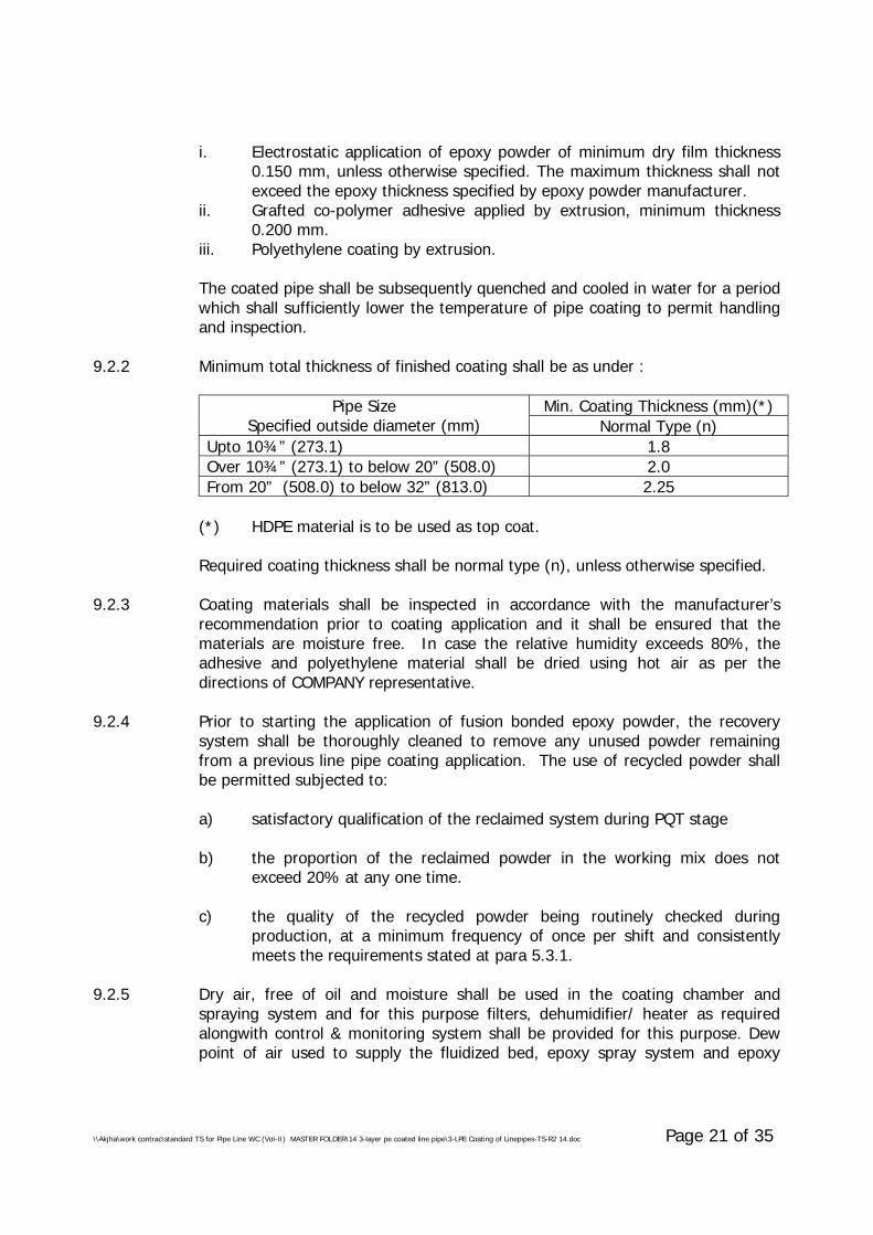
\\Akjha\work contrac\standard TS for Pipe Line WC (Vol-II) MASTER FOLDER\14 3-layer pe coated line pipe\3-LPE Coating of Linepipes-TS-R2 14.doc Page 21 of 35
i. Electrostatic application of epoxy powder of minimum dry film thickness0.150 mm, unless otherwise specified. The maximum thickness shall notexceed the epoxy thickness specified by epoxy powder manufacturer.
ii. Grafted co-polymer adhesive applied by extrusion, minimum thickness0.200 mm.
iii. Polyethylene coating by extrusion.
The coated pipe shall be subsequently quenched and cooled in water for a periodwhich shall sufficiently lower the temperature of pipe coating to permit handlingand inspection.
9.2.2 Minimum total thickness of finished coating shall be as under :
Min. Coating Thickness (mm)(*)Pipe SizeSpecified outside diameter (mm) Normal Type (n)
Upto 10¾” (273.1) 1.8Over 10¾” (273.1) to below 20” (508.0) 2.0From 20” (508.0) to below 32” (813.0) 2.25
(*) HDPE material is to be used as top coat.
Required coating thickness shall be normal type (n), unless otherwise specified.
9.2.3 Coating materials shall be inspected in accordance with the manufacturer’srecommendation prior to coating application and it shall be ensured that thematerials are moisture free. In case the relative humidity exceeds 80%, theadhesive and polyethylene material shall be dried using hot air as per thedirections of COMPANY representative.
9.2.4 Prior to starting the application of fusion bonded epoxy powder, the recoverysystem shall be thoroughly cleaned to remove any unused powder remainingfrom a previous line pipe coating application. The use of recycled powder shallbe permitted subjected to:
a) satisfactory qualification of the reclaimed system during PQT stage
b) the proportion of the reclaimed powder in the working mix does notexceed 20% at any one time.
c) the quality of the recycled powder being routinely checked duringproduction, at a minimum frequency of once per shift and consistentlymeets the requirements stated at para 5.3.1.
9.2.5 Dry air, free of oil and moisture shall be used in the coating chamber andspraying system and for this purpose filters, dehumidifier/ heater as requiredalongwith control & monitoring system shall be provided for this purpose. Dewpoint of air used to supply the fluidized bed, epoxy spray system and epoxy
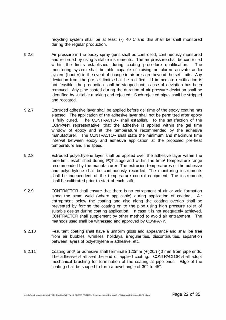
\\Akjha\work contrac\standard TS for Pipe Line WC (Vol-II) MASTER FOLDER\14 3-layer pe coated line pipe\3-LPE Coating of Linepipes-TS-R2 14.doc Page 22 of 35
recycling system shall be at least (-) 40°C and this shall be shall monitoredduring the regular production.
9.2.6 Air pressure in the epoxy spray guns shall be controlled, continuously monitoredand recorded by using suitable instruments. The air pressure shall be controlledwithin the limits established during coating procedure qualification. Themonitoring system shall be able capable of raising an alarm/ activate audiosystem (hooter) in the event of change in air pressure beyond the set limits. Anydeviation from the pre-set limits shall be rectified. If immediate rectification isnot feasible, the production shall be stopped until cause of deviation has beenremoved. Any pipe coated during the duration of air pressure deviation shall beidentified by suitable marking and rejected. Such rejected pipes shall be strippedand recoated.
9.2.7 Extruded adhesive layer shall be applied before gel time of the epoxy coating haselapsed. The application of the adhesive layer shall not be permitted after epoxyis fully cured. The CONTRACTOR shall establish, to the satisfaction of theCOMPANY representative, that the adhesive is applied within the gel timewindow of epoxy and at the temperature recommended by the adhesivemanufacturer. The CONTRACTOR shall state the minimum and maximum timeinterval between epoxy and adhesive application at the proposed pre-heattemperature and line speed.
9.2.8 Extruded polyethylene layer shall be applied over the adhesive layer within thetime limit established during PQT stage and within the time/ temperature rangerecommended by the manufacturer. The extrusion temperatures of the adhesiveand polyethylene shall be continuously recorded. The monitoring instrumentsshall be independent of the temperature control equipment. The instrumentsshall be calibrated prior to start of each shift.
9.2.9 CONTRACTOR shall ensure that there is no entrapment of air or void formationalong the seam weld (where applicable) during application of coating. Airentrapment below the coating and also along the coating overlap shall beprevented by forcing the coating on to the pipe using high pressure roller ofsuitable design during coating application. In case it is not adequately achieved,CONTRACTOR shall supplement by other method to avoid air entrapment. Themethods used shall be witnessed and approved by COMPANY.
9.2.10 Resultant coating shall have a uniform gloss and appearance and shall be freefrom air bubbles, wrinkles, holidays, irregularities, discontinuities, separationbetween layers of polyethylene & adhesive, etc.
9.2.11 Coating and/ or adhesive shall terminate 120mm (+)20/(-)0 mm from pipe ends.The adhesive shall seal the end of applied coating. CONTRACTOR shall adoptmechanical brushing for termination of the coating at pipe ends. Edge of thecoating shall be shaped to form a bevel angle of 30° to 45°.
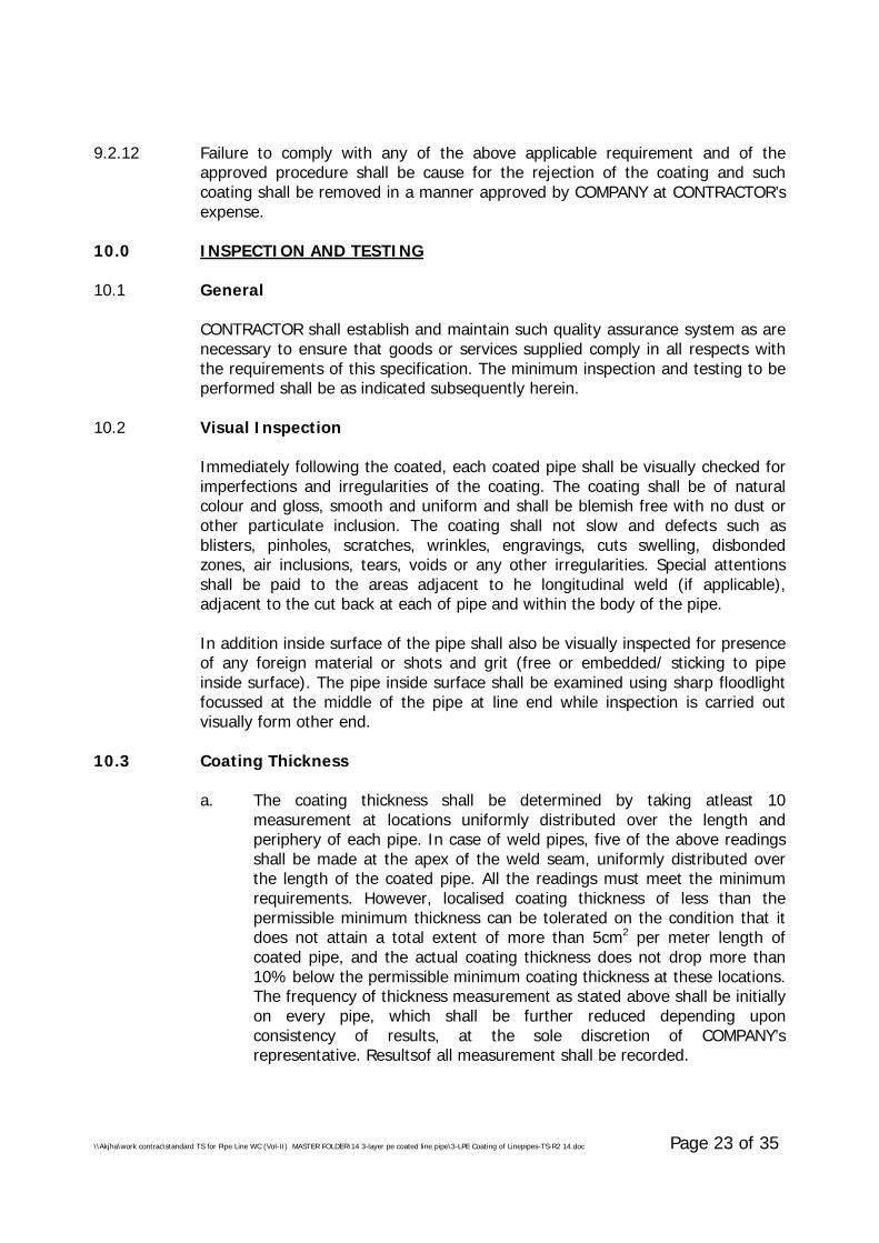
\\Akjha\work contrac\standard TS for Pipe Line WC (Vol-II) MASTER FOLDER\14 3-layer pe coated line pipe\3-LPE Coating of Linepipes-TS-R2 14.doc Page 23 of 35
9.2.12 Failure to comply with any of the above applicable requirement and of theapproved procedure shall be cause for the rejection of the coating and suchcoating shall be removed in a manner approved by COMPANY at CONTRACTOR’sexpense.
10.0 INSPECTION AND TESTING
10.1 General
CONTRACTOR shall establish and maintain such quality assurance system as arenecessary to ensure that goods or services supplied comply in all respects withthe requirements of this specification. The minimum inspection and testing to beperformed shall be as indicated subsequently herein.
10.2 Visual Inspection
Immediately following the coated, each coated pipe shall be visually checked forimperfections and irregularities of the coating. The coating shall be of naturalcolour and gloss, smooth and uniform and shall be blemish free with no dust orother particulate inclusion. The coating shall not slow and defects such asblisters, pinholes, scratches, wrinkles, engravings, cuts swelling, disbondedzones, air inclusions, tears, voids or any other irregularities. Special attentionsshall be paid to the areas adjacent to he longitudinal weld (if applicable),adjacent to the cut back at each of pipe and within the body of the pipe.
In addition inside surface of the pipe shall also be visually inspected for presenceof any foreign material or shots and grit (free or embedded/ sticking to pipeinside surface). The pipe inside surface shall be examined using sharp floodlightfocussed at the middle of the pipe at line end while inspection is carried outvisually form other end.
10.3 Coating Thickness
a. The coating thickness shall be determined by taking atleast 10measurement at locations uniformly distributed over the length andperiphery of each pipe. In case of weld pipes, five of the above readingsshall be made at the apex of the weld seam, uniformly distributed overthe length of the coated pipe. All the readings must meet the minimumrequirements. However, localised coating thickness of less than thepermissible minimum thickness can be tolerated on the condition that itdoes not attain a total extent of more than 5cm2 per meter length ofcoated pipe, and the actual coating thickness does not drop more than10% below the permissible minimum coating thickness at these locations.The frequency of thickness measurement as stated above shall be initiallyon every pipe, which shall be further reduced depending uponconsistency of results, at the sole discretion of COMPANY’srepresentative. Resultsof all measurement shall be recorded.
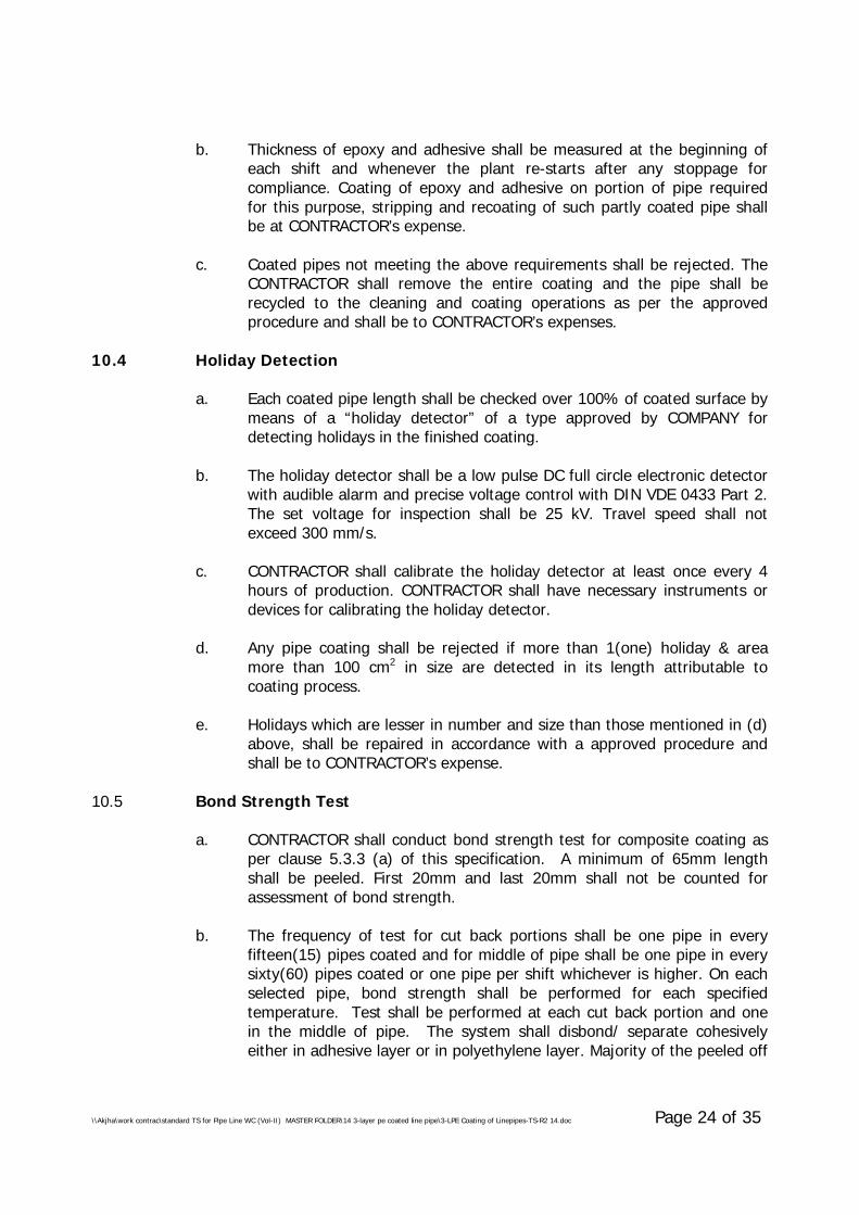
\\Akjha\work contrac\standard TS for Pipe Line WC (Vol-II) MASTER FOLDER\14 3-layer pe coated line pipe\3-LPE Coating of Linepipes-TS-R2 14.doc Page 24 of 35
b. Thickness of epoxy and adhesive shall be measured at the beginning ofeach shift and whenever the plant re-starts after any stoppage forcompliance. Coating of epoxy and adhesive on portion of pipe requiredfor this purpose, stripping and recoating of such partly coated pipe shallbe at CONTRACTOR’s expense.
c. Coated pipes not meeting the above requirements shall be rejected. TheCONTRACTOR shall remove the entire coating and the pipe shall berecycled to the cleaning and coating operations as per the approvedprocedure and shall be to CONTRACTOR’s expenses.
10.4 Holiday Detection
a. Each coated pipe length shall be checked over 100% of coated surface bymeans of a “holiday detector” of a type approved by COMPANY fordetecting holidays in the finished coating.
b. The holiday detector shall be a low pulse DC full circle electronic detectorwith audible alarm and precise voltage control with DIN VDE 0433 Part 2.The set voltage for inspection shall be 25 kV. Travel speed shall notexceed 300 mm/s.
c. CONTRACTOR shall calibrate the holiday detector at least once every 4hours of production. CONTRACTOR shall have necessary instruments ordevices for calibrating the holiday detector.
d. Any pipe coating shall be rejected if more than 1(one) holiday & areamore than 100 cm2 in size are detected in its length attributable tocoating process.
e. Holidays which are lesser in number and size than those mentioned in (d)above, shall be repaired in accordance with a approved procedure andshall be to CONTRACTOR’s expense.
10.5 Bond Strength Test
a. CONTRACTOR shall conduct bond strength test for composite coating asper clause 5.3.3 (a) of this specification. A minimum of 65mm lengthshall be peeled. First 20mm and last 20mm shall not be counted forassessment of bond strength.
b. The frequency of test for cut back portions shall be one pipe in everyfifteen(15) pipes coated and for middle of pipe shall be one pipe in everysixty(60) pipes coated or one pipe per shift whichever is higher. On eachselected pipe, bond strength shall be performed for each specifiedtemperature. Test shall be performed at each cut back portion and onein the middle of pipe. The system shall disbond/ separate cohesivelyeither in adhesive layer or in polyethylene layer. Majority of the peeled off
\\Akjha\work contrac\standard TS for Pipe Line WC (Vol-II) MASTER FOLDER\14 3-layer pe coated line pipe\3-LPE Coating of Linepipes-TS-R2 14.doc Page 25 of 35
area on the pipe shall show presence of adhesive. Disbondment/separation at epoxy to steel interface or epoxy/ adhesive interface oradhesive/ polyethylene interface shall not be permitted. The failure modeshall be recorded for each test.
c. In case the above tests do not comply with the above requirement,CONTRACTOR shall test all the preceding and succeeding coated pipes. Ifboth pipes pass the test, then the remainder of the pipe joints in thatshift shall be deemed satisfactory. If either pipe fails to meet thespecified requirements, all pipes coated during the shift shall be testeduntil the coating is provided acceptable. Rejected coated pipes shall bestripped and re-coated in accordance with approved procedure, atCONTRACTOR’s expense.
d. The frequency of bond strength test as per para 10.5(b) for cut backportion may be reduced depending upon the consistently of result to onepipe in every twenty five(25) instead of every fifteen pipes, at the solediscretion of the COMPANY Representative.
10.6 Impact Strength
a. Impact resistance test shall be conducted as per clause 5.3.3 (b) of thisspecification. Initially the frequency of test shall be 2(two) coated pipesper shift, which may be further reduced and/ or waived depending uponconsistently acceptable results at the sole discretion of COMPANY’srepresentative.
b. Minimum thirty(30) impacts located equidistant along the length ofcoated pipe shall be performed.
c. Immediately after testing, the test area shall be subjected to holidaydetection at the same voltage as used prior to impact strength test. Thepipe shall be rejected if any holiday is noted in the test area.
d. In case of test failure, retesting and disposal of coated pipe shall be asper 10.5(c) above.
10.7 Indentation Hardness
a. Indentation hardness test shall be as per clause 5.3.3 (c) of thisspecification. The frequency of test shall be initially 2(two) coated pipesper shift which shall be further reduced to one test each on 2 coatedpipes per week at random after 1 week of consistently acceptable results.Two samples for each temperature shall be taken from the cut backportion of coated pipe and one in middle of the pipe for this test.
b. In case of test failure, retesting and disposal of coated pipe shall be asper 10.5(c) above.
\\Akjha\work contrac\standard TS for Pipe Line WC (Vol-II) MASTER FOLDER\14 3-layer pe coated line pipe\3-LPE Coating of Linepipes-TS-R2 14.doc Page 26 of 35
10.8 Air Entrapment Test
a. Strips from bond strength tests or coated pipe may be used to helpdetermine the porosity of the finished coating. Strip shall be also cut fromlongitudinal weld (if applicable) at cut back portion and examined for thepresence of voids.
b. Bond strength strip shall be viewed from the side and at the failureinterface. At the pipe bond strength test location, utility knife shall beused to cut the edge of the coating to a 45° angle and view with amicroscope. Similar examination shall be done in the coating cut backarea.
c. One sample each either on the bond strength strip or coated pipe andstrip cut from the longitudinal weld (if applicable) shall be examined forair entrapment per shift. Strips shall be viewed from the side.
d. All examination shall done using a 30X magnification hand-heldmicroscope. The polyethylene and adhesive layers shall have no morethan 10% of the observed area taken up with air entrapment (porosity orbubbles). Air entrapment shall not occupy more than 10% of thethickness in each case. Bubbles shall not link together to provide amoisture path to the epoxy layer.
e. In case of test failure, retesting and disposal of coated pipe shall be asper 10.5(c) above.
10.9 Degree of Cure
a. Epoxy film samples shall be removed from cut back portion of the coatedpipe using hammer and cold chisel and the samples shall be taken forcure test using DSC procedure. Care shall be taken to remove thesamples of full film thickness avoiding inclusion of steel debris. Glasstransition temperature differential (∆Tg) and % cure (∆H) shall complythe specified requirements.
b. Frequency of this test shall be once per shift. Pipe shall be selectedrandomly by COMPANY Representative during the middle of a shift.Suitable provisions/ arrangements as per the instructions of COMPANYRepresentative shall be made by the CONTRACTOR for this purpose.
c. In case of test failure, production carried out during the entire shift shallbe rejected, unless the CONTRACTOR proposes a method to establish thecompliance with the degree of cure requirements of all pipes coatedduring that shift.
\\Akjha\work contrac\standard TS for Pipe Line WC (Vol-II) MASTER FOLDER\14 3-layer pe coated line pipe\3-LPE Coating of Linepipes-TS-R2 14.doc Page 27 of 35
10.10 Epoxy Layer Adhesive Test
a. Adhesion of epoxy layer shall be determined at ambient temperature bythe “St Andrews Cross” method i.e. by cutting two straight lines throughthe epoxy layer with a sharp knife. The incisions shall intersect at anangle of 30°/ 150°. The epoxy coating shall resist disbondment from thesteel when attempts are made to flick/ lift the coating from the 30° anglewith a sharp knife.
b. Frequency of this test shall be once per shift. The test shall be carried outat the cut back portion of the pipe from which the Degree of Cure testhas been carried out as per para 10.9 above.
c. In case of test failure, retesting and disposal of coated pipe shall be asper 10.9(c) above.
10.11 Cathodic Disbondment Test
a. 48 hours CD test shall be conducted as per clause 5.3.3. (h) of thisspecification.
b. The frequency of this test shall be once in every two weeks or one testrepresenting each batch of epoxy powder used, whichever is morefrequent.
c. In case the test fails to conform to the specified requirement, at theoption of the CONTRACTOR, all pipes coated after the previousacceptable test and prior to next acceptable test shall be rejected or thetest shall be repeated or the shall be repeated using two additionalsamples taken from the same end of the affected pipe.
When both retests conform to the specified requirement, the lot of pipesshall be accepted. When one or both the retests fail to conform to thespecified requirement, all coated pipes after previous acceptable test andprior to next acceptable shall be rejected. All rejected pipes shall bestripped, re-cleaned and re-coated. COMPANY may consider a furtherretest program to determine whether any of the affected pipe meet thecriteria for acceptance upon written request by the CONTRACTOR.
10.12 Damages occurring to pipe coating during above tests shall be repaired inaccordance with approved coating repair procedure.
10.13 Repairs occurring on account of the production test are however excluded fromabove mentioned limitations at para 10.4 (d) above.
10.14 COMPANY, reserves the right to perform inspection and witness tests on allactivities concerning the pipe coating operations starting from bare pipe tofinished coated pipe ready for dispatch and also testing of raw materials.

\\Akjha\work contrac\standard TS for Pipe Line WC (Vol-II) MASTER FOLDER\14 3-layer pe coated line pipe\3-LPE Coating of Linepipes-TS-R2 14.doc Page 28 of 35
CONTRACTOR shall give reasonable notice of time and shall provide withoutcharge reasonable access and facilities required for inspection to the COMPANY’sRepresentative. Inspection and tests performed or witnessed by COMPANY’sRepresentative shall in no way relieve the CONTRACTORs obligation to performthe required inspection and tests.
10.15 In case rate of defective or rejected pipes and/ or samples tests are 10% ormore for a single shift (typically 8 hours), CONTRACTOR shall be required to stopproduction and carry out a full and detailed investigation and shall submitfindings to COMPANY for approval. CONTRACTOR shall recommence theproduction only after getting the written permission from COMPANY.
Under no circumstances any action or omission of the COMPANY’s representativeshall relieve the CONTRACTOR of his responsibility for material and quality ofcoating produced. No pipes shall be transported from the coating plants unlessauthorised by COMPANY in writing.
11.0 HANDLING, TRANSPORTATION AND STORAGE
11.1 The CONTRACTOR shall be fully responsible for the pipe and for the pipeidentification marking from the time of “taking over” of bare pipe from COMPANYuntil such time that the coated line pipes are `handed over’ and/ or installed inthe permanent installation as the case may be according to the provisions of theContract.
At the time of “taking over” of bare pipes CONTRACTOR shall inspect and recordall the relevant details referred above including pipe defects in the presence ofCOMPANY. All pipes shall be checked for bevel damages, weld seam height,dents, gouges, corrosion and other damages. COMPANY Representative shalldecide whether pipe defects/ damages are suitable for repair. Damage to thepipes which occur after the CONTRACTOR has taken delivery such as dents,flats, or damage to the weld ends shall be cut off or removed and pipesrebevelled and repaired again as necessary. The cost of this work, as well as thatof the pipe lost in cutting and repair shall be to the CONTRACTOR’s account. Allsuch works shall be carried out after written approval of the COMPANY. Anyreduction in length shall be indicated in the CONTRACTOR’s pipe trackingsystem.
11.2 The CONTRACTOR shall unload, load, stockpile and transport the bare pipeswithin the coating plant(s) using suitable means and in a manner to avoiddamage to pipes.
The CONTRACTOR shall stockpile the bare pipes at the storage area of thecoating plant. The CONTRACTOR shall prepare and furnish to COMPANY aprocedure/ calculation generally in compliance with API RP-5L1 for pipe stacking,which shall be approved by COMPANY prior to commencement.
\\Akjha\work contrac\standard TS for Pipe Line WC (Vol-II) MASTER FOLDER\14 3-layer pe coated line pipe\3-LPE Coating of Linepipes-TS-R2 14.doc Page 29 of 35
11.3 The CONTRACTOR shall load, unload, transport and stockpile the coated pipeswithin the coating plant using approved suitable means and in a manner to avoiddamage to the pipe and coating. The procedure shall be approved by COMPANYprior to commencement of work.
11.4 Coated pipes may be handled by means of slings and belts of proper width(minimum 60mm) made of non-abrasive/ non-metallic materials. In this case,pipes to be stacked shall be separated row by row to avoid damages by rubbingthe coated surface in the process of taking off the slings. Use of round sectionalslings are prohibited. Fork lifts may be used provided that the arms of the forklift are covered with suitable pads preferably rubber.
11.5 Bare/ coated pipes at all times shall be stacked completely clear from the groundso that the bottom row of pipes remain free from any surface water. The pipesshall be stacked at a slope so that driving rain does not collect inside the pipe.Bare/ coated pipes may be stacked by placing them on ridges of sand free fromstones and covered with a plastic film or on wooden supports provided withsuitable cover. This cover can, for example, consist of dry, germ free straw witha plastic film, otherwise foam rubber may be used. The supports shall be spacedin such a manner as to avoid permanent bending of the pipes.
Stacks shall consist of limited number of layers such that the pressure exercisedby the pipe’s own weight does not cause damages to the coating. CONTRACTORshall submit calculations for COMPANY approval in this regard. Each pipe sectionshall be separated by means of spacers suitably spaced for this purpose. Stacksshall be suitably secured against falling down and shall consist of pipe sectionshaving the same diameter and wall thickness. The weld seam of pipes shall bepositioned always in a manner so as not to touch the adjacent pipes.
The ends of the pipes during handling and stacking shall always be protectedwith bevel protectors.
11.6 The lorries used for transportation shall be equipped with adequate pipesupports having as many round hollow beds as there as pipes to be placed onthe bottom of the lorry bed. Total width of the supports shall be at least 5% ofthe pipe length and min. 3 Nos. support shall be provided. These supports shallbe lined with a rubber protection and shall be spaced in a manner as to supportequal load from the pipes. The rubber protection must be free from all nails andstaples where pipes are in contact. The second layer and all following layers shallbe separated from the other with adequate number of separating layers ofprotective material such as straw in plastic covers or mineral wool strips orequivalent, to avoid direct touch between the coated pipes.
All stanchions of lorries used for transportation shall be covered by non-abrasivematerial like rubber belts or equivalent. Care shall be exercised to properly coverthe top of the stanchions and other positions such as reinforcement of the truckbody, rivets, etc. to prevent damage to the coated surface. Slings or non-metallic
\\Akjha\work contrac\standard TS for Pipe Line WC (Vol-II) MASTER FOLDER\14 3-layer pe coated line pipe\3-LPE Coating of Linepipes-TS-R2 14.doc Page 30 of 35
straps shall be used for securing loads during transportation. They shall besuitable padded at the contact points with the pipe.
11.7 Materials other than pipes and which are susceptible of deteriorating or sufferingfrom damages especially due to humidity, exposure to high thermal excursions orother advers weather conditions, shall be suitably stored and protected.Deteriorated materials shall not be used and shall be replaced at CONTRACTOR’sexpenses. These materials, shall always be handled during loading, unloadingand storage in a manner so as to prevent any damage, alteration and dispersion.When supplied in containers and envelopes, they shall bot be dropped or thrown,or removed by means of hooks, both during the handling operations till theircomplete use. During unloading transport and utilization, any contact with waterearth, crushed stone and any other foreign material shall be carefully avoided.
CONTRACTOR shall strictly follow Manufacturer’s instructions regarding storagetemperature and methods for volatile materials which are susceptible to changein properties and characteristics due to unsuitable storage. If necessary theCONTRACTOR shall provide for a proper conditioning.
11.8 In case of any marine transportation of bare/ coated line pipes involved, thesame shall be carried out in compliance with API RP 5LW. CONTRACTOR shallfurnish all details pertaining to marine transportation including necessarydrawings of cargo barges, storing/ stacking, sea fastening of pipes on thebarges/ marine vessels to the COMPANY for approval prior to undertaking suchtransportation works. In addition CONTRACTOR shall also carry out requisiteanalyses considering the proposed transportation scheme and establish the sameis safe and stable. On-deck overseas shipment shall not be allowed.
12.0 REPAIR OF COATING
CONTRACTOR shall submit to COMPANY, its methods and materials proposed tobe used for executing a coating repair and shall receive approval from COMPANYprior to use. In open storage the repair coating materials must be able towithstand a temperature of atleast +80°C, without impairing its serviceabilityand properties. CONTRACTOR shall furnish manufacturer’s test certificates forthe repair materials clearly establishing the compliance of the repair materialswith the applicable coating requirements indicated in this specification.
All pipe leaving coating plant, shall have sound external coating with no holidayporosity on 100% of the surface.
Defects, repairs and acceptability criteria shall be as follows :
• Pipes showing porosities or very small damage not picked up duringholiday test and having a surface less than 0.5 cm2 or linear damage(cut) of less than 3 cm shall be repaired by stick welding using material ofsame quality.
\\Akjha\work contrac\standard TS for Pipe Line WC (Vol-II) MASTER FOLDER\14 3-layer pe coated line pipe\3-LPE Coating of Linepipes-TS-R2 14.doc Page 31 of 35
• Damages caused to coating by handling such as scratches, cuts, dents,gouges, not picked up during holiday test, having a total reducedthickness on damaged portion not less than 2.0mm and an area notexceeding 20 cm2 shall be rebuild by heat shrink patch only and withoutexposing to bare metal.
• Defects or size exceeding above mentioned area or holidays of width lessthan 300 mm shall be repaired with heat shrinks repair patch by exposingthe bare metal surface.
• Defects exceeding the above and in number not exceeding 2 per pipe andlinear length not exceeding 500mm shall be repaired using heatshrinkable sleeves of HTLP80 or equivalent.
• Pipes with bigger damage shall be stripped and recoated.
• In case of coating defect close to coating cut back, CONTRACTOR shallremove the coating throughout the entire circumference of the pipe downto the steel surface and increase the coating cut back length. Now if thecoating cut back exceeds 140mm of linear length of pipe then the coatingshall be repaired by the use of heat shrinkable sleeves thereby making upthe coating cut back length of 120mm.
Not withstanding the above, under no circumstances, if the defects exceeds70mm from the original coating cut back length, the entire coating shall beremoved and the pipe shall be recycled through the entire coating procedure.
Irrespective of type of repair, the maximum nos of repair of coating shall be asfollows :
• Holiday repair of size ≤ 100 cm2 attributable to process of coatingapplication shall be maximum of one per pipe.
• In addition to the above, defects to be repaired by heat shrink patch/sleeve shall be maximum 2(two) per pipe.
Defects exceeding the above limits shall cause pipe coating rejection, strippingand recoating. The above is exclusive of the repairs warranted due to testing asper this specification.
All repairs carried out to coating for whatever reason shall be to the account ofCONTRACTOR.
Cosmetic damages occurring only in the Polyethylene layer only need not berepaired by exposing upto steel surface, as deemed fit by the COMPANYrepresentative. In any case the CONTRACTOR shall establish his material,methods and procedure of repair that results in acceptable quality of product bytesting and shall receive approval from COMPANY prior to use.
\\Akjha\work contrac\standard TS for Pipe Line WC (Vol-II) MASTER FOLDER\14 3-layer pe coated line pipe\3-LPE Coating of Linepipes-TS-R2 14.doc Page 32 of 35
Testing of repairs shall be in the same form as testing coating. All repairs shallresult in a coating thickness no less than the parent coating thickness.CONTRACTOR shall test repairs to coating as and when required by COMPANY.
13.0 MARKING
CONTRACTOR shall place marking on the outside surface of the coating at oneend of the coated pipe, and marking shall indicate, but not limited to thefollowing information:
a. Pipe number, Heat numberb. Diameter & Wall Thicknessc. Coated Pipe Numberd. Colour bande. Any other information considered relevant by COMPANY.f. Pipe Manufacturer Nameg. Inspection Mark/ Punch
CONTRACTOR shall obtain prior approval on making procedure to be adoptedfrom the COMPANY.
14.0 QUALITY ASSURANCE
14.1 The CONTRACTOR shall have established within the organisation and, shalloperate for the contract, a documented Quality System that ensures that therequirements of this specification are met in all aspects. The Quality System shallbe based upon ISO 9001/2 or equivalent.
14.2 The CONTRACTOR shall have established a Quality Assurance Group within itsorganisation that shall be responsible for reviewing the Quality System andensuring that it is implemented.
14.3 The CONTRACTOR shall submit the procedures that comprise the Quality Systemto the COMPANY for agreement.
14.4 The CONTRACTOR’s Quality System shall pay particular attention to the controlof Suppliers and sub-contractors and shall ensure that the requirements of thisspecification are satisfied by the Suppliers and Sub-contractors operating Qualitysystem in their organisation.
14.5 The CONTRACTOR shall, prior to the commencement of work, prepare and issuea Quality plan for all of the activities required to satisfy the requirements of thisspecification. The plan shall include any sub-contracted work, for which the sub-contractors Quality plans shall be submitted. The plan shall be sufficientlydetailed to indicate sequentially for each discipline the requisite quality control,inspection , testing and certification activities with reference to the relevantprocedures and the acceptance standards.
\\Akjha\work contrac\standard TS for Pipe Line WC (Vol-II) MASTER FOLDER\14 3-layer pe coated line pipe\3-LPE Coating of Linepipes-TS-R2 14.doc Page 33 of 35
14.6 The CONTRACTOR’s Quality system and associated procedures may, with duenotice, be subject to formal audits. The application of quality control by theCONTRACTOR will be monitored by the COMPANY Representatives who willwitness and accept the inspection testing and associated work required by thisspecification.
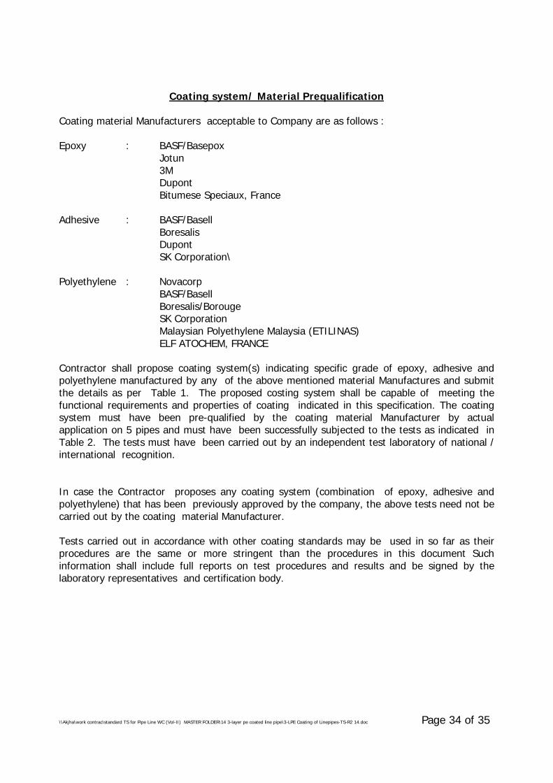
\\Akjha\work contrac\standard TS for Pipe Line WC (Vol-II) MASTER FOLDER\14 3-layer pe coated line pipe\3-LPE Coating of Linepipes-TS-R2 14.doc Page 34 of 35
Coating system/ Material Prequalification
Coating material Manufacturers acceptable to Company are as follows :
Epoxy : BASF/BasepoxJotun3MDupontBitumese Speciaux, France
Adhesive : BASF/BasellBoresalisDupontSK Corporation\
Polyethylene : NovacorpBASF/BasellBoresalis/BorougeSK CorporationMalaysian Polyethylene Malaysia (ETILINAS)ELF ATOCHEM, FRANCE
Contractor shall propose coating system(s) indicating specific grade of epoxy, adhesive andpolyethylene manufactured by any of the above mentioned material Manufactures and submitthe details as per Table 1. The proposed costing system shall be capable of meeting thefunctional requirements and properties of coating indicated in this specification. The coatingsystem must have been pre-qualified by the coating material Manufacturer by actualapplication on 5 pipes and must have been successfully subjected to the tests as indicated inTable 2. The tests must have been carried out by an independent test laboratory of national /international recognition.
In case the Contractor proposes any coating system (combination of epoxy, adhesive andpolyethylene) that has been previously approved by the company, the above tests need not becarried out by the coating material Manufacturer.
Tests carried out in accordance with other coating standards may be used in so far as theirprocedures are the same or more stringent than the procedures in this document Suchinformation shall include full reports on test procedures and results and be signed by thelaboratory representatives and certification body.
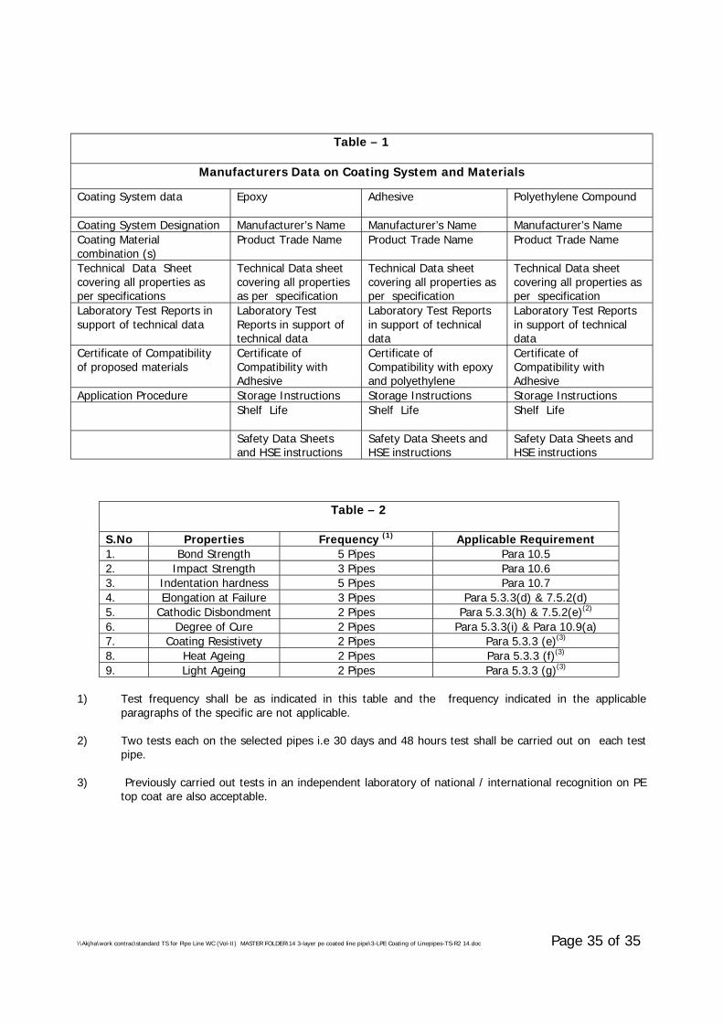
\\Akjha\work contrac\standard TS for Pipe Line WC (Vol-II) MASTER FOLDER\14 3-layer pe coated line pipe\3-LPE Coating of Linepipes-TS-R2 14.doc Page 35 of 35
Table – 1
Manufacturers Data on Coating System and Materials
Coating System data Epoxy Adhesive Polyethylene Compound
Coating System Designation Manufacturer’s Name Manufacturer’s Name Manufacturer’s NameCoating Materialcombination (s)
Product Trade Name Product Trade Name Product Trade Name
Technical Data Sheetcovering all properties asper specifications
Technical Data sheetcovering all propertiesas per specification
Technical Data sheetcovering all properties asper specification
Technical Data sheetcovering all properties asper specification
Laboratory Test Reports insupport of technical data
Laboratory TestReports in support oftechnical data
Laboratory Test Reportsin support of technicaldata
Laboratory Test Reportsin support of technicaldata
Certificate of Compatibilityof proposed materials
Certificate ofCompatibility withAdhesive
Certificate ofCompatibility with epoxyand polyethylene
Certificate ofCompatibility withAdhesive
Application Procedure Storage Instructions Storage Instructions Storage InstructionsShelf Life Shelf Life Shelf Life
Safety Data Sheetsand HSE instructions
Safety Data Sheets andHSE instructions
Safety Data Sheets andHSE instructions
Table – 2
S.No Properties Frequency (1) Applicable Requirement1. Bond Strength 5 Pipes Para 10.52. Impact Strength 3 Pipes Para 10.63. Indentation hardness 5 Pipes Para 10.74. Elongation at Failure 3 Pipes Para 5.3.3(d) & 7.5.2(d)5. Cathodic Disbondment 2 Pipes Para 5.3.3(h) & 7.5.2(e)(2)
6. Degree of Cure 2 Pipes Para 5.3.3(i) & Para 10.9(a)7. Coating Resistivety 2 Pipes Para 5.3.3 (e)(3)
8. Heat Ageing 2 Pipes Para 5.3.3 (f)(3)
9. Light Ageing 2 Pipes Para 5.3.3 (g)(3)
1) Test frequency shall be as indicated in this table and the frequency indicated in the applicableparagraphs of the specific are not applicable.
2) Two tests each on the selected pipes i.e 30 days and 48 hours test shall be carried out on each testpipe.
3) Previously carried out tests in an independent laboratory of national / international recognition on PEtop coat are also acceptable.
\\Akjha\work contrac\standard TS for Pipe Line WC (Vol-II) MASTER FOLDER\25 Seamless Fitting & Flange upto 16 inch\TS - Seamless Fittings & Flanges - 025-R1.doc
PROCESS & PIPING DESIGN SECTIONMECON LIMITEDDELHI 110 092
TECHNICAL SPECIFICATIONFOR
SEAMLESS FITTINGS AND FLANGESUPTO 400mm (16”) NB
SPECIFICATION NO. : MEC/TS/05/62/025, Rev-1
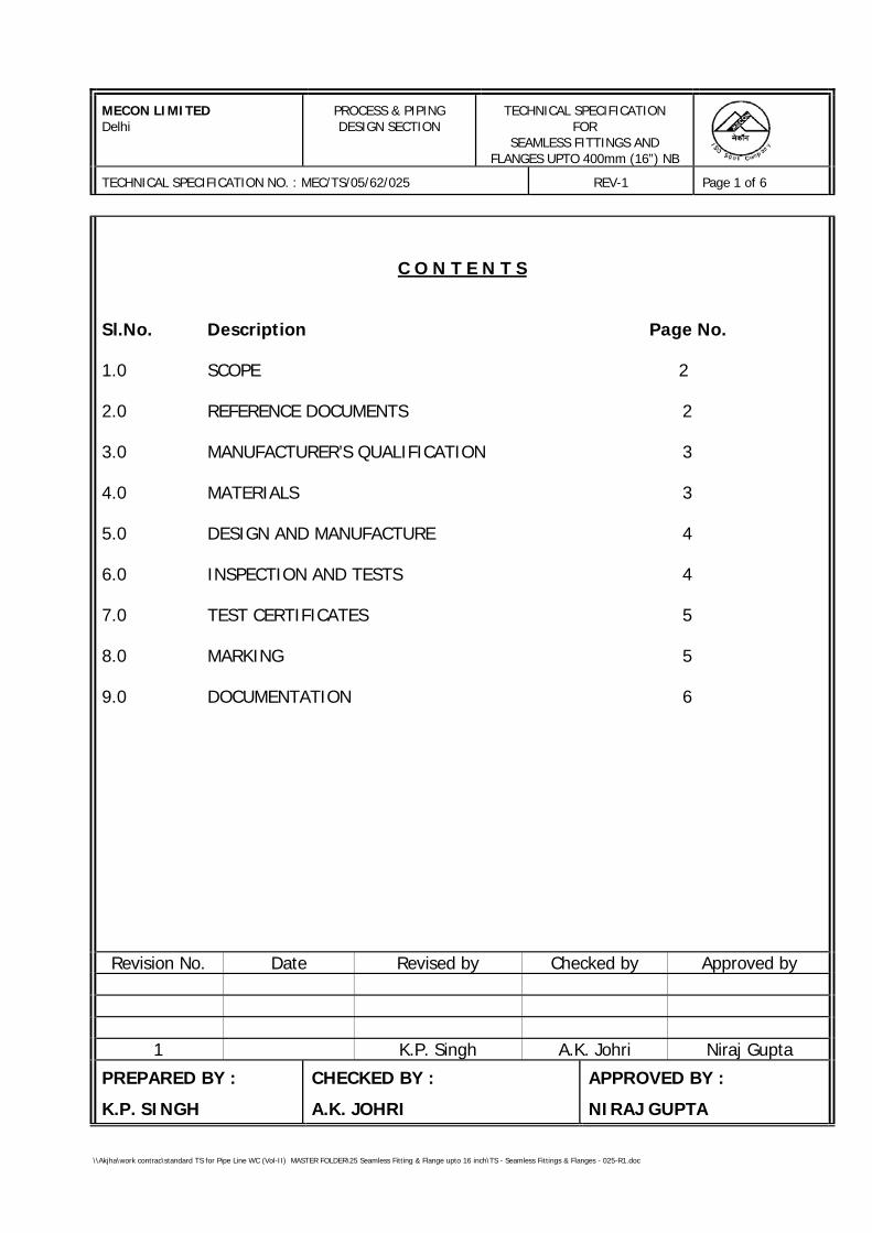
MECON LIMITEDDelhi
PROCESS & PIPINGDESIGN SECTION
TECHNICAL SPECIFICATIONFOR
SEAMLESS FITTINGS ANDFLANGES UPTO 400mm (16”) NB
TECHNICAL SPECIFICATION NO. : MEC/TS/05/62/025 REV-1 Page 1 of 6
\\Akjha\work contrac\standard TS for Pipe Line WC (Vol-II) MASTER FOLDER\25 Seamless Fitting & Flange upto 16 inch\TS - Seamless Fittings & Flanges - 025-R1.doc
C O N T E N T S
Sl.No. Description Page No.
1.0 SCOPE 2
2.0 REFERENCE DOCUMENTS 2
3.0 MANUFACTURER’S QUALIFICATION 3
4.0 MATERIALS 3
5.0 DESIGN AND MANUFACTURE 4
6.0 INSPECTION AND TESTS 4
7.0 TEST CERTIFICATES 5
8.0 MARKING 5
9.0 DOCUMENTATION 6
Revision No. Date Revised by Checked by Approved by
1 K.P. Singh A.K. Johri Niraj Gupta
PREPARED BY :
K.P. SINGH
CHECKED BY :
A.K. JOHRI
APPROVED BY :
NIRAJ GUPTA
MECON LIMITEDDelhi
PROCESS & PIPINGDESIGN SECTION
TECHNICAL SPECIFICATIONFOR
SEAMLESS FITTINGS ANDFLANGES UPTO 400mm (16”) NB
TECHNICAL SPECIFICATION NO. : MEC/TS/05/62/025 REV-1 Page 2 of 6
\\Akjha\work contrac\standard TS for Pipe Line WC (Vol-II) MASTER FOLDER\25 Seamless Fitting & Flange upto 16 inch\TS - Seamless Fittings & Flanges - 025-R1.doc
1.0 SCOPE
This specification covers the minimum requirements for the design,manufacture and supply of following items to be installed in pipeline systemhandling hydrocarbons in liquid or gaseous phase:
- Seamless fittings 400 mm (16”) NB and smaller, such as tees, elbows,reducers and caps.
- Flanges 400 mm (16”) NB and smaller, such as welding neck flangesand blind flanges.
The specification does not cover the above mentioned items which are to beinstalled in pipeline system handling sour hydrocarbons (liquid/ gas) serviceas defined in NACE standard MR-01-75-98.
2.0 REFERENCE DOCUMENTS
Reference has been made in this specification to the latest edition of thefollowing codes, standards and specifications:
a) ASME B 16.5 - Steel Pipe Flanges and Flanged Fittings
b) ASME B 16.9 - Factory-Made Wrought Steel ButtWelding Fittings
c) ASME B 16.11 - Forged Steel Fittings, Socket Weldingand Threaded
d) ASME B 31.4 - Liquid Transportation Systems for Hydrocarbons, Liquid Petroleum Gas, Anhydrous Ammonia and Alcohols
e) ASME B 31.8 - Gas Transmission and DistributionPiping Systems
f) ASTM A 370 - Mechanical Testing of Steel Products
g) API 590 - Steel Line Blanks
h) MSS-SP-25 - Standard Marking System for Valves, Fittings, Flanges and Unions
MECON LIMITEDDelhi
PROCESS & PIPINGDESIGN SECTION
TECHNICAL SPECIFICATIONFOR
SEAMLESS FITTINGS ANDFLANGES UPTO 400mm (16”) NB
TECHNICAL SPECIFICATION NO. : MEC/TS/05/62/025 REV-1 Page 3 of 6
\\Akjha\work contrac\standard TS for Pipe Line WC (Vol-II) MASTER FOLDER\25 Seamless Fitting & Flange upto 16 inch\TS - Seamless Fittings & Flanges - 025-R1.doc
i) MSS-SP-44 - Steel Pipeline Flanges
j) MSS-SP-75 - Specification for High Test Wrought Welded Fittings
k) MSS-SP-97 - Forged Carbon Steel Branch OutletFittings-Socket Welding, Threadedand Butt Welding Ends
3.0 MANUFACTURER’S QUALIFICATION
Manufacturer who intends bidding for fittings, must possess the records of asuccessful proof test, in accordance with the provisions of ASME B 16.9/ MSS-SP-75, as applicable. These records shall be submitted at the time of bidding.
4.0 MATERIALS
4.1 The basic material for fittings and flanges shall be as indicated in the MaterialRequisition. Additionally, the material shall also meet the requirementsspecified hereinafter.
4.2 Each heat of steel used for the manufacture of fittings and flanges shall havecarbon equivalent (CE) not greater than 0.45% calculated from check analysisin accordance with following formula :
Mn Cr + Mo + V Ni + CuCE = C + ------- + --------------------- + ---------------
6 5 15
Carbon contents on check analysis shall not exceed 0.22%.
4.3 Unless specified otherwise, Charpy V-notch test shall be conduced for eachheat of steel, in accordance with the impact test provision of ASTM A370 at0°C temperature. The average absorbed impact energy values of three full-sized specimens shall be 27 joules.
The minimum impact energy value of any one specimen of the threespecimens analysed as above, shall not be less than 80% of the above-mentioned average value.
MECON LIMITEDDelhi
PROCESS & PIPINGDESIGN SECTION
TECHNICAL SPECIFICATIONFOR
SEAMLESS FITTINGS ANDFLANGES UPTO 400mm (16”) NB
TECHNICAL SPECIFICATION NO. : MEC/TS/05/62/025 REV-1 Page 4 of 6
\\Akjha\work contrac\standard TS for Pipe Line WC (Vol-II) MASTER FOLDER\25 Seamless Fitting & Flange upto 16 inch\TS - Seamless Fittings & Flanges - 025-R1.doc
4.4 Steel used shall be fully killed.
4.5 Hardness testing shall be carried out by Manufacturer in accordance withASTM A 234. Hardness testing shall cover at least 10% per item, per size, perheat per manufacturing method.
5.0 DESIGN AND MANUFACTURE
5.1 Flanges such as welding neck flanges and blind flanges shall conform to therequirements of ASME B 16.5. Spectacle blind, spacer & blind shall conform toAPI 590.
5.2 Fittings such as tees, elbows and reducers shall be seamless type and shallconform to ASME B 16.9 for sizes 50 mm (2”)NB and above and ASME B16.11for sizes below 50mm(2”)NB.
5.3 Fittings such as weldolets, sockolets, nippolets, etc., shall be manufactured inaccordance with MSS-SP-97.
5.4 Type, face and face finish of flanges shall be as specified in MaterialRequisition.
5.5 Stub-in or pipe to pipe connection shall not be used in the manufacture oftees. Tees shall be manufactured by forging or extrusion methods. Thelongitudinal weld seam shall be kept at 90° from the extrusion. Fittings shallnot have any circumferential joint .
5.6 All butt weld ends shall be beveled as per ASME B16.25.
5.7 Repair by welding on flanges and parent metal of the fittings is not allowed.
6.0 INSPECTION AND TESTS
6.1 The Manufacturer shall perform all inspection and tests as per the requirementof this specification and the relevant codes, prior to shipment at his works. Such inspection and tests shall be, but not limited to, the following:
6.1.1 Visual inspection.
6.1.2 Dimensional checks.
MECON LIMITEDDelhi
PROCESS & PIPINGDESIGN SECTION
TECHNICAL SPECIFICATIONFOR
SEAMLESS FITTINGS ANDFLANGES UPTO 400mm (16”) NB
TECHNICAL SPECIFICATION NO. : MEC/TS/05/62/025 REV-1 Page 5 of 6
\\Akjha\work contrac\standard TS for Pipe Line WC (Vol-II) MASTER FOLDER\25 Seamless Fitting & Flange upto 16 inch\TS - Seamless Fittings & Flanges - 025-R1.doc
6.1.3 Chemical composition, mechanical properties and hardness examination.
6.1.4 All finished wrought weld ends shall be 100% ultrasonically tested forlamination type defects. Any lamination larger than 6.35 mm shall not beacceptable.
6.1.5 All other tests not specifically listed but are required as per applicablestandard/ specification.
6.2 Purchaser’s Inspector may also perform stage-wise inspection and witnesstests as indicated in Clause 6.1 at Manufacture's Works prior to shipment.Manufacturer shall give reasonable notice of time and shall provide, withoutcharge, reasonable access and facilities required for inspection to thePurchaser’s Inspector.
Inspection and tests performed/ witnessed by the Purchaser’s Inspector shallin no way relieve the Manufacturer's obligation to perform the requiredinspection and tests.
7.0 TEST CERTIFICATES
Manufacturer shall submit following certificates to Purchaser’s Inspector:
a) Test certificates relevant to the chemical analysis and mechanicalproperties of the materials used for construction as per this specificationand relevant standards.
b) Test reports on non-destructive testing.
8.0 MARKING
Each item shall be marked with indelible paint with the following data:
a) Manufacturer's marking
b) Material Specification
c) Size and schedule number
d) Heat number
MECON LIMITEDDelhi
PROCESS & PIPINGDESIGN SECTION
TECHNICAL SPECIFICATIONFOR
SEAMLESS FITTINGS ANDFLANGES UPTO 400mm (16”) NB
TECHNICAL SPECIFICATION NO. : MEC/TS/05/62/025 REV-1 Page 6 of 6
\\Akjha\work contrac\standard TS for Pipe Line WC (Vol-II) MASTER FOLDER\25 Seamless Fitting & Flange upto 16 inch\TS - Seamless Fittings & Flanges - 025-R1.doc
9.0 DOCUMENTATION
9.1 At the time of bidding, Manufacturer shall submit the following documents:
a) Reference list of previous supplies of similar fittings of similarspecification.
b) Clausewise list of deviations from this specification, if any.c) Brief description of the manufacturing and quality control facilities at
Manufacturer's works.d) Manufacturer's qualification requirement as per clause 3.0 of this
specification.e) Quality Assurance Plan (QAP) enclosed with this tender duly signed,
stamped and accepted.
9.2 Prior to shipment, Manufacturer shall submit six copies of test certificates aslisted in clause 7.0 of this specification.
9.3 All documents shall be in English language.
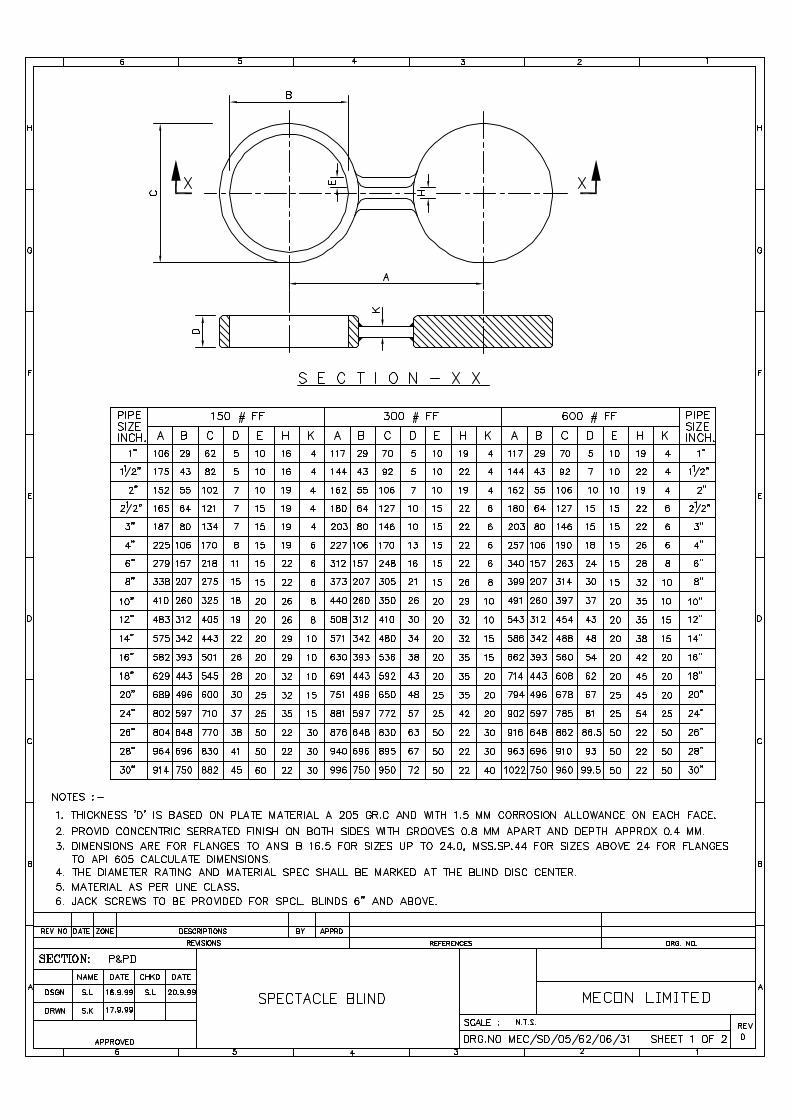
\\Akjha\work contrac\standard TS for Pipe Line WC (Vol-II) MASTER FOLDER\26 flange & welded fittings 18 inch & above\Specification for Flanges & Welded Fittings 26.doc
PROCESS & PIPING DESIGN SECTIONMECON LIMITEDDELHI 110 092
TECHNICAL SPECIFICATIONFOR
FLANGES AND WELDED FITTINGS(SIZE 450mm (18”) NB AND ABOVE)
SPECIFICATION NO. : MEC/TS/05/62/026, R-0
MECON LIMITEDDelhi
PROCESS & PIPINGDESIGN SECTION
TECHNICAL SPECIFICATIONFOR
FLANGES AND WELDED FITTINGS(SIZE 450mm (18”) NB AND ABOVE)
TECHNICAL SPECIFICATION NO. : MEC/TS/05/62/026 REV-0 PAGE 1 OF 9
\\Akjha\work contrac\standard TS for Pipe Line WC (Vol-II) MASTER FOLDER\26 flange & welded fittings 18 inch & above\Specification for Flanges & Welded Fittings 26.doc
C O N T E N T S
Sl.No. Description Page No.
1.0 SCOPE 2
2.0 REFERENCE DOCUMENTS 2
3.0 MANUFACTURER’S QUALIFICATION 3
4.0 MATERIALS 3
5.0 DESIGN AND MANUFACTURE 5
6.0 INSPECTION AND TESTS 6
7.0 TEST CERTIFICATES 7
8.0 PAINTING, MARKING AND SHIPMENT 8
9.0 DOCUMENTATION 9
Prepared By : Checked By : Approved By :
MECON LIMITEDDelhi
PROCESS & PIPINGDESIGN SECTION
TECHNICAL SPECIFICATIONFOR
FLANGES AND WELDED FITTINGS(SIZE 450mm (18”) NB AND ABOVE)
TECHNICAL SPECIFICATION NO. : MEC/TS/05/62/026 REV-0 PAGE 2 OF 9
\\Akjha\work contrac\standard TS for Pipe Line WC (Vol-II) MASTER FOLDER\26 flange & welded fittings 18 inch & above\Specification for Flanges & Welded Fittings 26.doc
1.0 SCOPE
This specification covers the minimum requirements for the design,manufacture and supply of following items to be installed in pipelinesystem handling hydrocarbons in liquid or gaseous phase :
• Carbon Steel Welded Fittings 450mm (18”) NB and above, such astees, elbows, reducers and caps.
• Carbon Steel Flanges 450mm (18”) NB and above, such as weldingneck flanges and blind flanges.
This specification does not cover the above mentioned items which are tobe installed in pipeline system handling sour hydrocarbons (liquid/ gas)service as defined in NACE Standard MR-01-75.
2.0 REFERENCE DOCUMENTS
2.1 Reference has been made in this specification to the latest edition of thefollowing Codes, Standards and Specifications:
a) ASME B31.8 - Gas Transmission and Distribution PipingSystems
b) ASME B31.4 - Pipeline Transportation Systems for LiquidHydrocarbons, Liquid Petroleum Gas,Anhydrous Ammonia and Alcohols
c) ASME B16.5 - Steel Pipe Flanges and Flanged Fittings
d) ASME B16.9 - Factory Made Wrought Steel Butt WeldingFittings
e) ASME B16.47 - Large Diameter Steel Flanges
f) ASME B16.25 - Butt-welding Ends
MECON LIMITEDDelhi
PROCESS & PIPINGDESIGN SECTION
TECHNICAL SPECIFICATIONFOR
FLANGES AND WELDED FITTINGS(SIZE 450mm (18”) NB AND ABOVE)
TECHNICAL SPECIFICATION NO. : MEC/TS/05/62/026 REV-0 PAGE 3 OF 9
\\Akjha\work contrac\standard TS for Pipe Line WC (Vol-II) MASTER FOLDER\26 flange & welded fittings 18 inch & above\Specification for Flanges & Welded Fittings 26.doc
g) ASME Sec VIII/IX - Boiler and Pressure Vessel Code
h) ASTM A370 - Standard Test Methods and Definitions forMechanical Testing of Steel Products
i) MSS-SP-75 - Specification for High Test Wrought WeldedFittings
j) MSS-SP-44 - Steel Pipeline Flanges
2.2 In case of conflict between the requirements of this specification and therequirement of above referred Codes and Standards, the requirements ofthis specification shall govern.
3.0 MANUFACTURER’S QUALIFICATION
The design of fittings shall be established by mathematical analysiscontained in ASME Sec. VIII/ ASME B31.3. The design of fittings forwhich mathematical analysis is not available shall be established by prooftesting. These records shall be submitted at the time of bidding,qualifying the complete range of fittings offered. Manufacturer whointends bidding for fittings must posses the records of a successful prooftest in accordance with the provisions of ASME B16.9 and/ or MSS-SP-75.These records shall be submitted at the time of bidding, qualifying thecomplete range of fittings offered. Failure to submit such records at thetime of bidding may become a cause of rejection of the offer.
4.0 MATERIALS
4.1 The steel used in the manufacture of fittings and flanges shall be fullykilled carbon steel with a grain size of ASTM 7 or finer as defined in ASTME112. This requirement shall not apply to quenched and temperedfittings. The basic material for fittings and flanges shall be as indicated inthe Material Requisition. Additionally, the material shall also meet therequirements specified hereinafter.
MECON LIMITEDDelhi
PROCESS & PIPINGDESIGN SECTION
TECHNICAL SPECIFICATIONFOR
FLANGES AND WELDED FITTINGS(SIZE 450mm (18”) NB AND ABOVE)
TECHNICAL SPECIFICATION NO. : MEC/TS/05/62/026 REV-0 PAGE 4 OF 9
\\Akjha\work contrac\standard TS for Pipe Line WC (Vol-II) MASTER FOLDER\26 flange & welded fittings 18 inch & above\Specification for Flanges & Welded Fittings 26.doc
4.2 Each heat of steel used for the manufacture of fittings and flanges shallhave carbon equivalent (CE) not greater than 0.45 calculated from checkanalysis in accordance with the following formula:
Mn Cr + Mo + V Ni + CuCE = C + --------- + ------------------- + ------------
6 5 15
4.3 Carbon contents on check analysis shall not exceed 0.22%.
4.4 Unless specified otherwise, Charpy V-notch test shall be conducted at 0°Ctemperature for each heat of steel, in accordance with the impact testprovisions of ASTM A370 for flanges and MSS-SP-75 for all fittings.
The average absorbed impact energy values of three full-sized specimensshall be 27 joules. The minimum impact energy value of any onespecimen of the three specimens analysed as above, shall not be less than80% of the above mentioned average value. In addition, the averageshear area shall comply the requirements of MSS-SP-75.
4.5 Hardness test shall be carried out as per ASTM A370 for each heat of steelused. A full thickness cross-section shall be taken for this purpose andthe maximum hardness of base metal, weld metal and heat affected zoneshall not exceed 248 HV10.
4.6 One transverse guided weld bend test shall be performed for each lot ofwelded fittings produced from the same heat in accordance withprovisions of MSS-SP-75. The dimension “A” in guided bend test shall notexceed 4.0 times the nominal wall thickness and dimension “B” shall beequal to A+2t+3.2mm, where “t” is nominal wall thickness.
4.7 One transverse weld tensile test shall be conducted on each heat/ lot ofwelded fittings in accordance with the requirements of MSS-SP-75.
MECON LIMITEDDelhi
PROCESS & PIPINGDESIGN SECTION
TECHNICAL SPECIFICATIONFOR
FLANGES AND WELDED FITTINGS(SIZE 450mm (18”) NB AND ABOVE)
TECHNICAL SPECIFICATION NO. : MEC/TS/05/62/026 REV-0 PAGE 5 OF 9
\\Akjha\work contrac\standard TS for Pipe Line WC (Vol-II) MASTER FOLDER\26 flange & welded fittings 18 inch & above\Specification for Flanges & Welded Fittings 26.doc
5.0 DESIGN AND MANUFACTURE
5.1 Flanges such as weld neck flanges and blind flanges shall conform to therequirements of ASME B16.5 upto size DN 600mm (24”) excluding DN550mm (22”), MSS-SP-44 for sizes DN 550mm (22”) and ASME B16.47 forsizes DN 650mm (26”) and above.
5.2 Spectacle blind and Spacer & blind shall conform to the requirements ofAPI 590 upto sizes DN 600mm (24”). For sizes above DN 650mm (26”)and above, Spectacle blind and Spacer & blind shall conform toManufacturer’s standard.
5.3 Type, face and face finish of flanges shall be as specified in MaterialRequisition.
5.4 Fittings such as tees, elbows and reducers shall be either welded orseamless type. All fittings shall comply with the requirements of MSS-SP-75.
5.5 Tees shall be manufactured by forging or extrusion method. Stub-in orpipe to pipe connection shall not be used in the manufacture of tees. Thelongitudinal weld seam shall be kept at 90° from the extrusion. Fittingsshall not have any circumferential weld joint.
5.6 All butt weld ends shall be bevelled as per ASME B16.5/ MSS-SP-44/ ASMEB16.47 as applicable for flanges and MSS-SP-75 for fittings.
5.7 The reinforcement of inside weld seam shall be removed for a distance of100mm from each end of welded fittings.
5.8 All welds shall be made by welders and welding procedures qualified inaccordance with provisions of ASME Sec. IX. The procedure qualificationshall include impact test for weld/ heat affected zone, hardness test andguided bend test and shall meet the requirements of Clauses 4.4, 4.5 and4.6 of this specification, respectively.
MECON LIMITEDDelhi
PROCESS & PIPINGDESIGN SECTION
TECHNICAL SPECIFICATIONFOR
FLANGES AND WELDED FITTINGS(SIZE 450mm (18”) NB AND ABOVE)
TECHNICAL SPECIFICATION NO. : MEC/TS/05/62/026 REV-0 PAGE 6 OF 9
\\Akjha\work contrac\standard TS for Pipe Line WC (Vol-II) MASTER FOLDER\26 flange & welded fittings 18 inch & above\Specification for Flanges & Welded Fittings 26.doc
5.9 Repair by welding on flanges and parent metal of fittings is not allowed.Repair of weld seam by welding shall be carried out by welders andwelding procedures duly qualified as per ASME Section IX and API 1104and records for each repair shall be maintained. Repair weldingprocedure qualification shall include all tests which are applicable forregular production welding procedure qualification.
6.0 INSPECTION AND TESTS
6.1 The Manufacturer shall perform all inspections and tests as per therequirement of this specification and the relevant codes, prior to shipmentat his works. Such inspections and tests shall be, but not limited to, thefollowing :
6.1.1 All fittings and flanges shall be visually inspected. The internal andexternal surfaces of the fittings shall be free from any strikes, gouges,burrs and other detrimental defects.
6.1.2 Dimensional checks shall be carried out on finished products as per ASMEB16.5/ MSS-SP-44/ ASME B16.47 as applicable for flanges and ASMEB16.9/ MSS-SP-75 as applicable for fittings and as per this specification.Fittings not covered in MSS-SP-75 shall be checked as per Manufacturer’sstandard.
6.1.3 Chemical composition and mechanical properties shall be checked as perrelevant material standards and this specification, for each heat of steelused.
6.1.4 The non-destructive inspection shall be carried out as given below :
a) All butt and repair welds for welded fittings shall be examined100% by radiography. Acceptance limits shall be as per API 1104.
b) When elbows of size > 18” NB are manufactured, the first elbow ofeach radius, diameter and wall thickness shall be ultrasonicallychecked for sufficient wall thickness in areas where a minimum wall
MECON LIMITEDDelhi
PROCESS & PIPINGDESIGN SECTION
TECHNICAL SPECIFICATIONFOR
FLANGES AND WELDED FITTINGS(SIZE 450mm (18”) NB AND ABOVE)
TECHNICAL SPECIFICATION NO. : MEC/TS/05/62/026 REV-0 PAGE 7 OF 9
\\Akjha\work contrac\standard TS for Pipe Line WC (Vol-II) MASTER FOLDER\26 flange & welded fittings 18 inch & above\Specification for Flanges & Welded Fittings 26.doc
thickness is to be expected. This shall be followed by randominspection of one out of every three elbows of the same radius,diameter and wall thickness.
c) All finished wrought weld ends shall be 100% tested for laminationtype defects by ultrasonic test. Any lamination larger than 6.35mmshall not be acceptable.
d) Magnetic particle or liquid penetrant examination shall beperformed on cold formed butt welding tees with extruded outlets,that are subjected to an extreme fiber elongation of greater than5% shall be carried out as per the Supplementary Requirement SR3of MSS-SP-75.
e) Welds which cannot be inspected by radiographic methods shall bechecked by ultrasonic or magnetic particle methods. Acceptancecriteria shall be as per ASME Section VIII Appendix 12 andAppendix 6, respectively.
6.2 Purchaser’s Inspector reserves the right to perform stagewise inspectionand witness tests, as indicated in Clause 6.1 of this specification atManufacturer’s Works prior to shipment. Manufacturer shall givereasonable notice of time and shall provide, without charge, reasonableaccess and facilities required for inspection, to the Purchaser’s Inspector.Inspection and tests performed/ witnessed by Purchaser’s Inspector shallin no way relieve the Manufacturer’s obligation to perform the requiredinspection and tests.
7.0 TEST CERTIFICATES
Manufacturer shall furnish the following certificates :
a) Test certificates relevant to the chemical and mechanical propertiesof the materials used for manufacture of flanges and fittings as perrelevant standards and this specification.
MECON LIMITEDDelhi
PROCESS & PIPINGDESIGN SECTION
TECHNICAL SPECIFICATIONFOR
FLANGES AND WELDED FITTINGS(SIZE 450mm (18”) NB AND ABOVE)
TECHNICAL SPECIFICATION NO. : MEC/TS/05/62/026 REV-0 PAGE 8 OF 9
\\Akjha\work contrac\standard TS for Pipe Line WC (Vol-II) MASTER FOLDER\26 flange & welded fittings 18 inch & above\Specification for Flanges & Welded Fittings 26.doc
b) Test Reports on radiography, ultrasonic inspection and magneticparticle examination.
c) Test reports of heat treatment carried out as per the specification.
d) Welding procedures and welders’ qualification reports.
e) Test certificates for each fitting stating that it is capable ofwithstanding without leakage a test pressure which results in ahoop stress equivalent to 100% of the specified minimum yieldstrength for the pipe with which the fitting is to be attachedwithout impairment of serviceability.
8.0 PAINTING, MARKING AND SHIPMENT
8.1 After all required inspection and tests have been carried out, all externalsurfaces shall be thoroughly cleaned to remove grease, dust & rust andshall be applied with standard mill coating for protection against corrosionduring transit and storage. The coating shall be easily removable in thefield. Manufacturer shall furnish the details of paint used at the time ofbidding.
8.2 Ends of all fittings and weld neck flanges shall be suitably protected toavoid any damage during transit. Metallic or high impact plastic bevelprotectors shall be provided for fittings and flanges. Flange face shall besuitably protected to avoid any damage during transit.
8.3 All fittings and flanges shall be marked as per MSS-SP-25.
8.4 Package shall be marked legibly with suitable marking ink to indicate thefollowing :
a) Manufacturer’s Nameb) Type of flange(s) and fittings(s)c) Nominal diameter, thickness and material graded) Purchase order number and item serial number
MECON LIMITEDDelhi
PROCESS & PIPINGDESIGN SECTION
TECHNICAL SPECIFICATIONFOR
FLANGES AND WELDED FITTINGS(SIZE 450mm (18”) NB AND ABOVE)
TECHNICAL SPECIFICATION NO. : MEC/TS/05/62/026 REV-0 PAGE 9 OF 9
\\Akjha\work contrac\standard TS for Pipe Line WC (Vol-II) MASTER FOLDER\26 flange & welded fittings 18 inch & above\Specification for Flanges & Welded Fittings 26.doc
9.0 DOCUMENTATION
9.1 Manufacturer shall furnish at the time of bidding, the followingdocuments:
a) Reference list of similar supplies including all relevant details, viz.Project, Year, Client, Location, Size and Service.
b) Record of successful qualification test of fittings in compliance withthe requirement of this specification.
c) Brief description of the manufacturing, heat treatment and qualitycontrol facilities of the Manufacturer’s Works.
d) Clause-wise list of deviations from this specification, if any.
9.2 Within three weeks of placement of order, Manufacturer shall submit fourcopies of method of manufacture, testing and quality control procedurefor raw material and finished product for Purchaser’s approval.
Once the approval has been given by Purchaser, any changes in design,material and method of manufacture shall be notified to the Purchaser,whose approval in writing of all changes shall be obtained before theflanges and fittings are manufactured.
9.3 Within four weeks from the approval date, Manufacturer shall submit sixcopies of all documents as listed in Clause 9.2 of this specification.
9.4 Prior to shipment, the Manufacturer shall submit six copies of the testcertificates as listed in Clause 7.0 of this specification.
9.5 All documents shall be in English Language only.
\\Akjha\work contrac\standard TS for Pipe Line WC (Vol-II) MASTER FOLDER\59A assorted pipe spec\Specification for Assorted Pipes 59A.doc
PROCESS & PIPING DESIGN SECTIONMECON LIMITEDDELHI 110 092
TECHNICAL SPECIFICATIONFOR
ASSORTED PIPES
SPECIFICATION NO. : MEC/TS/05/62/59A, R-0
MECON LIMITEDDelhi
PROCESS & PIPINGDESIGN SECTION
TECHNICAL SPECIFICATIONFOR
ASSORTED PIPES
TECHNICAL SPECIFICATION NO. : MEC/TS/05/62/59A REV-0 PAGE 1 OF 9
\\Akjha\work contrac\standard TS for Pipe Line WC (Vol-II) MASTER FOLDER\59A assorted pipe spec\Specification for Assorted Pipes 59A.doc
C O N T E N T S
Sl.No. Description Page No.
1.0 GENERAL 2
2.0 IBR PIPES 4
3.0 HYDROSTATIC TEST 5
4.0 MARKING & DESPATCH 5
ANNEXURE-I : HYDROSTATIC TEST 7
Prepared By : Checked By : Approved By :
MECON LIMITEDDelhi
PROCESS & PIPINGDESIGN SECTION
TECHNICAL SPECIFICATIONFOR
ASSORTED PIPES
TECHNICAL SPECIFICATION NO. : MEC/TS/05/62/59A REV-0 PAGE 2 OF 9
\\Akjha\work contrac\standard TS for Pipe Line WC (Vol-II) MASTER FOLDER\59A assorted pipe spec\Specification for Assorted Pipes 59A.doc
1.0 GENERAL
1.1 All pipes and their dimensions, tolerances, chemical composition, physicalproperties, heat treatment, hydrotest and other testing and markingrequirements shall conform to the latest codes and standards specified inthe Material Requisition (MR). Deviation(s), if any, shall be clearlyhighlighted in the offer.
1.2 Testing
1.2.1 Test reports shall be supplied for all mandatory tests as per the applicablematerial specifications. Test reports shall also be furnished for anysupplementary tests as specified in the MR & Clauses 1.10 & 1.11.
1.2.2 Material test certificates (physical property, chemical composition &treatment report) shall also be furnished for the pipes supplied.
1.3 Manufacturing Processes
1.3.1 Steel made by Acid Bessemer Process shall not be acceptable.
1.3.2 All longitudinally welded pipes other than IS:3589 should employautomatic welding.
1.4 Pipe shall be supplied in single or double random length of 4 to 7 and 7 to14 meters, respectively.
1.5 a) Seamless and E.R.W. pipes shall not have any circumferential seamjoint in a random length. However, in case of E.FS.W. pipe, in onerandom length one welded circumferential seam of same quality aslongitudinal weld is permitted. This weld shall be at least 2.5 mfrom either end. The longitudinal seams of the two portions shallbe staggered by 90°. Single random length in such cases shall be 5to 7m.
b) Unless otherwise mentioned in the respective material code,E.FS.W. pipes < 36” shall not have more than one longitudinalseam joint and E.FS.W. pipes ≥ 36” shall not have more than twolongitudinal seam joints.
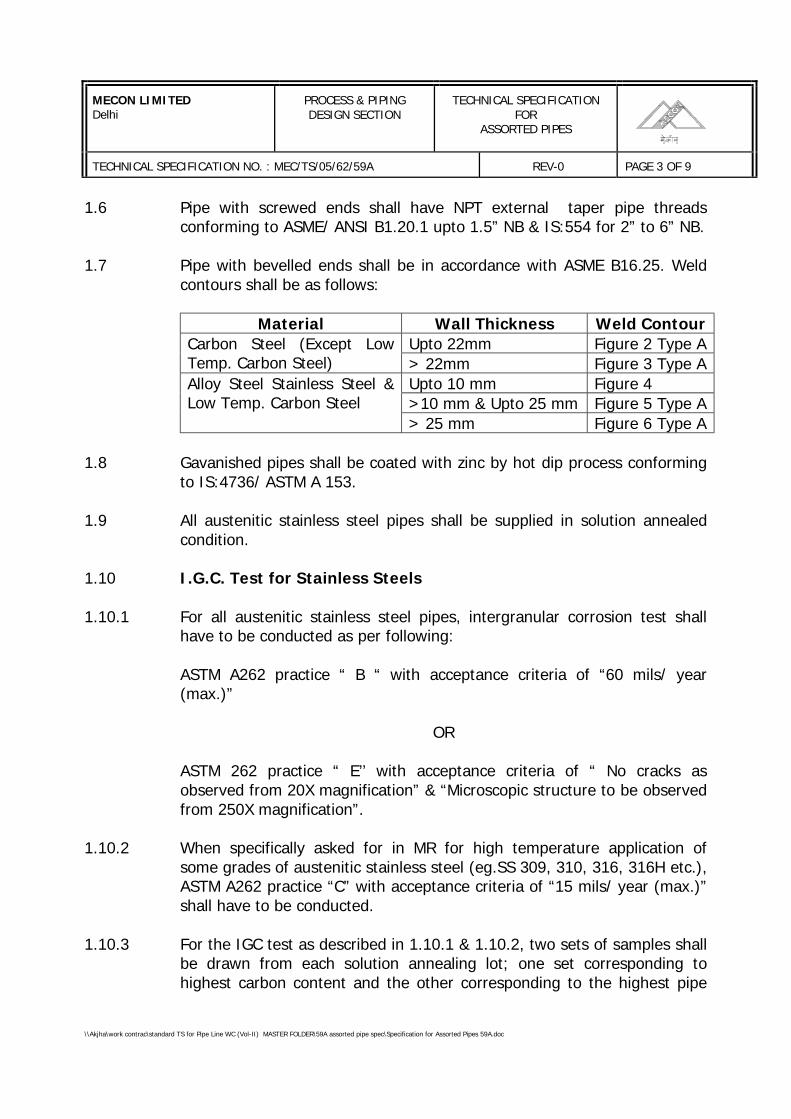
MECON LIMITEDDelhi
PROCESS & PIPINGDESIGN SECTION
TECHNICAL SPECIFICATIONFOR
ASSORTED PIPES
TECHNICAL SPECIFICATION NO. : MEC/TS/05/62/59A REV-0 PAGE 3 OF 9
\\Akjha\work contrac\standard TS for Pipe Line WC (Vol-II) MASTER FOLDER\59A assorted pipe spec\Specification for Assorted Pipes 59A.doc
1.6 Pipe with screwed ends shall have NPT external taper pipe threadsconforming to ASME/ ANSI B1.20.1 upto 1.5” NB & IS:554 for 2” to 6” NB.
1.7 Pipe with bevelled ends shall be in accordance with ASME B16.25. Weldcontours shall be as follows:
Material Wall Thickness Weld ContourUpto 22mm Figure 2 Type ACarbon Steel (Except Low
Temp. Carbon Steel) > 22mm Figure 3 Type AUpto 10 mm Figure 4>10 mm & Upto 25 mm Figure 5 Type A
Alloy Steel Stainless Steel &Low Temp. Carbon Steel
> 25 mm Figure 6 Type A
1.8 Gavanished pipes shall be coated with zinc by hot dip process conformingto IS:4736/ ASTM A 153.
1.9 All austenitic stainless steel pipes shall be supplied in solution annealedcondition.
1.10 I.G.C. Test for Stainless Steels
1.10.1 For all austenitic stainless steel pipes, intergranular corrosion test shallhave to be conducted as per following:
ASTM A262 practice “ B “ with acceptance criteria of “60 mils/ year(max.)”
OR
ASTM 262 practice “ E’’ with acceptance criteria of “ No cracks asobserved from 20X magnification” & “Microscopic structure to be observedfrom 250X magnification”.
1.10.2 When specifically asked for in MR for high temperature application ofsome grades of austenitic stainless steel (eg.SS 309, 310, 316, 316H etc.),ASTM A262 practice “C” with acceptance criteria of “15 mils/ year (max.)”shall have to be conducted.
1.10.3 For the IGC test as described in 1.10.1 & 1.10.2, two sets of samples shallbe drawn from each solution annealing lot; one set corresponding tohighest carbon content and the other corresponding to the highest pipe
MECON LIMITEDDelhi
PROCESS & PIPINGDESIGN SECTION
TECHNICAL SPECIFICATIONFOR
ASSORTED PIPES
TECHNICAL SPECIFICATION NO. : MEC/TS/05/62/59A REV-0 PAGE 4 OF 9
\\Akjha\work contrac\standard TS for Pipe Line WC (Vol-II) MASTER FOLDER\59A assorted pipe spec\Specification for Assorted Pipes 59A.doc
thickness. When testing in is conducted as per Practice “E”, photograph ofmicroscopic structure shall be submitted for record.
1.11 All welded pipes indicated as ‘CRYO’ & ‘LT’ in MR shall be impact testedper requirement and acceptance criteria of ASME B31.3. The impact testtemperature shall be –196° C & -45° C for stainless steel and carbonsteel, respectively, unless specifically mentioned otherwise in MR.
1.12 Pipes under ‘NACE’ category shall meet the requirements given inMR-01-75.
1.13 Specified heat treatment for carbon steel & alloy steel and solutionannealing for stainless steel pipes shall be carried out after weld repairs.Number of weld repairs at the same spot shall be restricted to maximumtwo by approved repair procedure.
1.14 For black or galvanised pipes to IS:1239, the minimum percentage ofelongation shall be 20%.
2.0 IBR PIPES
2.1 IBR Documentation
2.1.1 Pipes under purview of IBR shall be accompanied with IBR certificateoriginal in Form IIIA, duly approved and countersigned by IBR authority/local authority empowered by the Central Boiler Board of India. Photocopyof the original certificate duly attested by the local boiler inspector wherethe supplier is located is the minimum requirement for acceptance.
2.1.2 For materials 1 ¼ Cr- ½ Mo (ASTM A335 Gr. P11/ A691 Gr. 1 ¼ Cr) & 2¼ Cr-1Mo (ASTM A335 Gr.P22/ A691 Gr. 2 ¼ Cr.), from III-A approvedby IBR shall include the tabulation of Et , Sc & Sr values for the entiretemperature range given below. Et , Sc & Sr values shall be such thatthroughout the temperature range
Et / 1.5 ≥Sr / 1.5 ≥ Sa
Sc ≥where,SA : Allowable stress at the working metal temperature.Et : Yield point (0.2% proof stress at the working metal
temperature).
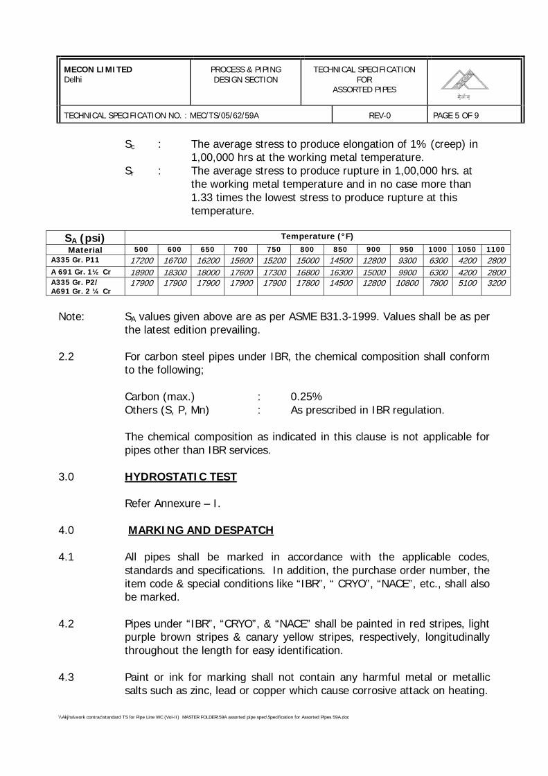
MECON LIMITEDDelhi
PROCESS & PIPINGDESIGN SECTION
TECHNICAL SPECIFICATIONFOR
ASSORTED PIPES
TECHNICAL SPECIFICATION NO. : MEC/TS/05/62/59A REV-0 PAGE 5 OF 9
\\Akjha\work contrac\standard TS for Pipe Line WC (Vol-II) MASTER FOLDER\59A assorted pipe spec\Specification for Assorted Pipes 59A.doc
Sc : The average stress to produce elongation of 1% (creep) in 1,00,000 hrs at the working metal temperature.
Sr : The average stress to produce rupture in 1,00,000 hrs. atthe working metal temperature and in no case more than1.33 times the lowest stress to produce rupture at this temperature.
SA (psi) Temperature (°F)
Material 500 600 650 700 750 800 850 900 950 1000 1050 1100A335 Gr. P11 17200 16700 16200 15600 15200 15000 14500 12800 9300 6300 4200 2800A 691 Gr. 1½ Cr 18900 18300 18000 17600 17300 16800 16300 15000 9900 6300 4200 2800A335 Gr. P2/A691 Gr. 2 ¼ Cr
17900 17900 17900 17900 17900 17800 14500 12800 10800 7800 5100 3200
Note: SA values given above are as per ASME B31.3-1999. Values shall be as perthe latest edition prevailing.
2.2 For carbon steel pipes under IBR, the chemical composition shall conformto the following;
Carbon (max.) : 0.25%Others (S, P, Mn) : As prescribed in IBR regulation.
The chemical composition as indicated in this clause is not applicable forpipes other than IBR services.
3.0 HYDROSTATIC TEST
Refer Annexure – I.
4.0 MARKING AND DESPATCH
4.1 All pipes shall be marked in accordance with the applicable codes,standards and specifications. In addition, the purchase order number, theitem code & special conditions like “IBR”, “ CRYO”, “NACE”, etc., shall alsobe marked.
4.2 Pipes under “IBR”, “CRYO”, & “NACE” shall be painted in red stripes, lightpurple brown stripes & canary yellow stripes, respectively, longitudinallythroughout the length for easy identification.
4.3 Paint or ink for marking shall not contain any harmful metal or metallicsalts such as zinc, lead or copper which cause corrosive attack on heating.
MECON LIMITEDDelhi
PROCESS & PIPINGDESIGN SECTION
TECHNICAL SPECIFICATIONFOR
ASSORTED PIPES
TECHNICAL SPECIFICATION NO. : MEC/TS/05/62/59A REV-0 PAGE 6 OF 9
\\Akjha\work contrac\standard TS for Pipe Line WC (Vol-II) MASTER FOLDER\59A assorted pipe spec\Specification for Assorted Pipes 59A.doc
4.4 Pipes shall be dry, clen and free from from moisture, dirt and looseforeign materials of any kind.
4.5 Pipes shall be protected from rust, corrosion and mechanical damageduring transportation, shipment and storage.
4.6 Rust preventive used on machined surfaces to be welded shall be easilyremovable with a petroleum solvent and the same shall not be harmful towelding.
4.7 Both ends of the pipe shall be protected with the following material:
Plain end : Plastic capBevel end : Wood, Metal or Plastic coverThreaded end : Metal or Plastic threaded cap
4.8 End protectors to be used on bevelled ends shall be securely and tightlyattached with belt or wire.
4.9 Steel end protectors to be used on galvanised pipes shall be galvanised.
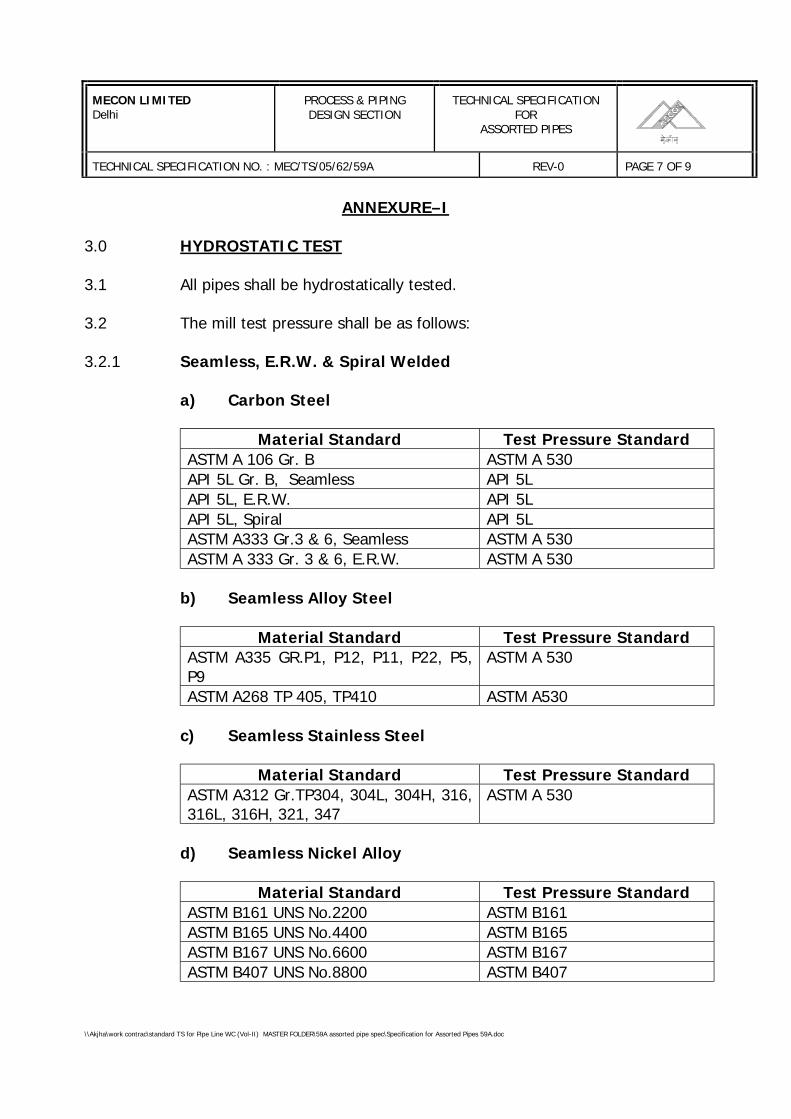
MECON LIMITEDDelhi
PROCESS & PIPINGDESIGN SECTION
TECHNICAL SPECIFICATIONFOR
ASSORTED PIPES
TECHNICAL SPECIFICATION NO. : MEC/TS/05/62/59A REV-0 PAGE 7 OF 9
\\Akjha\work contrac\standard TS for Pipe Line WC (Vol-II) MASTER FOLDER\59A assorted pipe spec\Specification for Assorted Pipes 59A.doc
ANNEXURE–I
3.0 HYDROSTATIC TEST
3.1 All pipes shall be hydrostatically tested.
3.2 The mill test pressure shall be as follows:
3.2.1 Seamless, E.R.W. & Spiral Welded
a) Carbon Steel
Material Standard Test Pressure StandardASTM A 106 Gr. B ASTM A 530API 5L Gr. B, Seamless API 5LAPI 5L, E.R.W. API 5LAPI 5L, Spiral API 5LASTM A333 Gr.3 & 6, Seamless ASTM A 530ASTM A 333 Gr. 3 & 6, E.R.W. ASTM A 530
b) Seamless Alloy Steel
Material Standard Test Pressure StandardASTM A335 GR.P1, P12, P11, P22, P5,P9
ASTM A 530
ASTM A268 TP 405, TP410 ASTM A530
c) Seamless Stainless Steel
Material Standard Test Pressure StandardASTM A312 Gr.TP304, 304L, 304H, 316,316L, 316H, 321, 347
ASTM A 530
d) Seamless Nickel Alloy
Material Standard Test Pressure StandardASTM B161 UNS No.2200 ASTM B161ASTM B165 UNS No.4400 ASTM B165ASTM B167 UNS No.6600 ASTM B167ASTM B407 UNS No.8800 ASTM B407
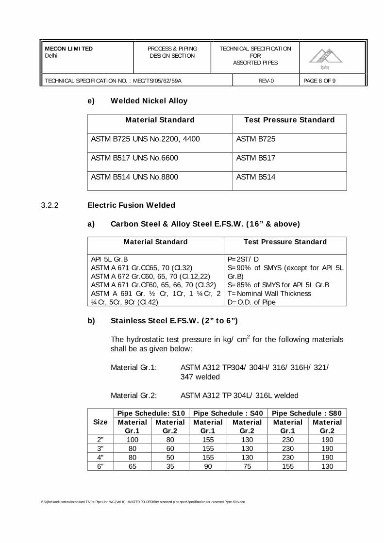
MECON LIMITEDDelhi
PROCESS & PIPINGDESIGN SECTION
TECHNICAL SPECIFICATIONFOR
ASSORTED PIPES
TECHNICAL SPECIFICATION NO. : MEC/TS/05/62/59A REV-0 PAGE 8 OF 9
\\Akjha\work contrac\standard TS for Pipe Line WC (Vol-II) MASTER FOLDER\59A assorted pipe spec\Specification for Assorted Pipes 59A.doc
e) Welded Nickel Alloy
Material Standard Test Pressure Standard
ASTM B725 UNS No.2200, 4400 ASTM B725
ASTM B517 UNS No.6600 ASTM B517
ASTM B514 UNS No.8800 ASTM B514
3.2.2 Electric Fusion Welded
a) Carbon Steel & Alloy Steel E.FS.W. (16” & above)
Material Standard Test Pressure Standard
API 5L Gr.BASTM A 671 Gr.CC65, 70 (Cl.32)ASTM A 672 Gr.C60, 65, 70 (Cl.12,22)ASTM A 671 Gr.CF60, 65, 66, 70 (Cl.32)ASTM A 691 Gr. ½ Cr, 1Cr, 1 ¼Cr, 2¼Cr, 5Cr, 9Cr (Cl.42)
P=2ST/ DS=90% of SMYS (except for API 5LGr.B)S=85% of SMYS for API 5L Gr.BT=Nominal Wall ThicknessD=O.D. of Pipe
b) Stainless Steel E.FS.W. (2” to 6”)
The hydrostatic test pressure in kg/ cm2 for the following materialsshall be as given below:
Material Gr.1: ASTM A312 TP304/ 304H/ 316/ 316H/ 321/ 347 welded
Material Gr.2: ASTM A312 TP 304L/ 316L welded
Pipe Schedule: S10 Pipe Schedule : S40 Pipe Schedule : S80Size Material
Gr.1Material
Gr.2Material
Gr.1Material
Gr.2Material
Gr.1Material
Gr.22” 100 80 155 130 230 1903” 80 60 155 130 230 1904” 80 50 155 130 230 1906” 65 35 90 75 155 130
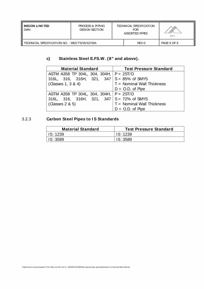
MECON LIMITEDDelhi
PROCESS & PIPINGDESIGN SECTION
TECHNICAL SPECIFICATIONFOR
ASSORTED PIPES
TECHNICAL SPECIFICATION NO. : MEC/TS/05/62/59A REV-0 PAGE 9 OF 9
\\Akjha\work contrac\standard TS for Pipe Line WC (Vol-II) MASTER FOLDER\59A assorted pipe spec\Specification for Assorted Pipes 59A.doc
c) Stainless Steel E.FS.W. (8” and above).
Material Standard Test Pressure StandardASTM A358 TP 304L, 304, 304H,316L, 316, 316H, 321, 347(Classes 1, 3 & 4)
P = 2ST/DS = 85% of SMYST = Nominal Wall ThicknessD = O.D. of Pipe
ASTM A358 TP 304L, 304, 304H,316L, 316, 316H, 321, 347(Classes 2 & 5)
P = 2ST/DS = 72% of SMYST = Nominal Wall ThicknessD = O.D. of Pipe
3.2.3 Carbon Steel Pipes to IS Standards
Material Standard Test Pressure StandardIS :1239 IS :1239IS :3589 IS :3589
SPECIFICATIONFOR
PIPELINE PRE-COMMISSIONING ANDCOMMISSIONING
OFPIPELINE PROJECT
SPECIFICATION NO. MEC/S/05/62/61, R-1
(PROCESS & PIPELINE DESIGN SECTION)MECON LIMITED
DELHI - 110 092
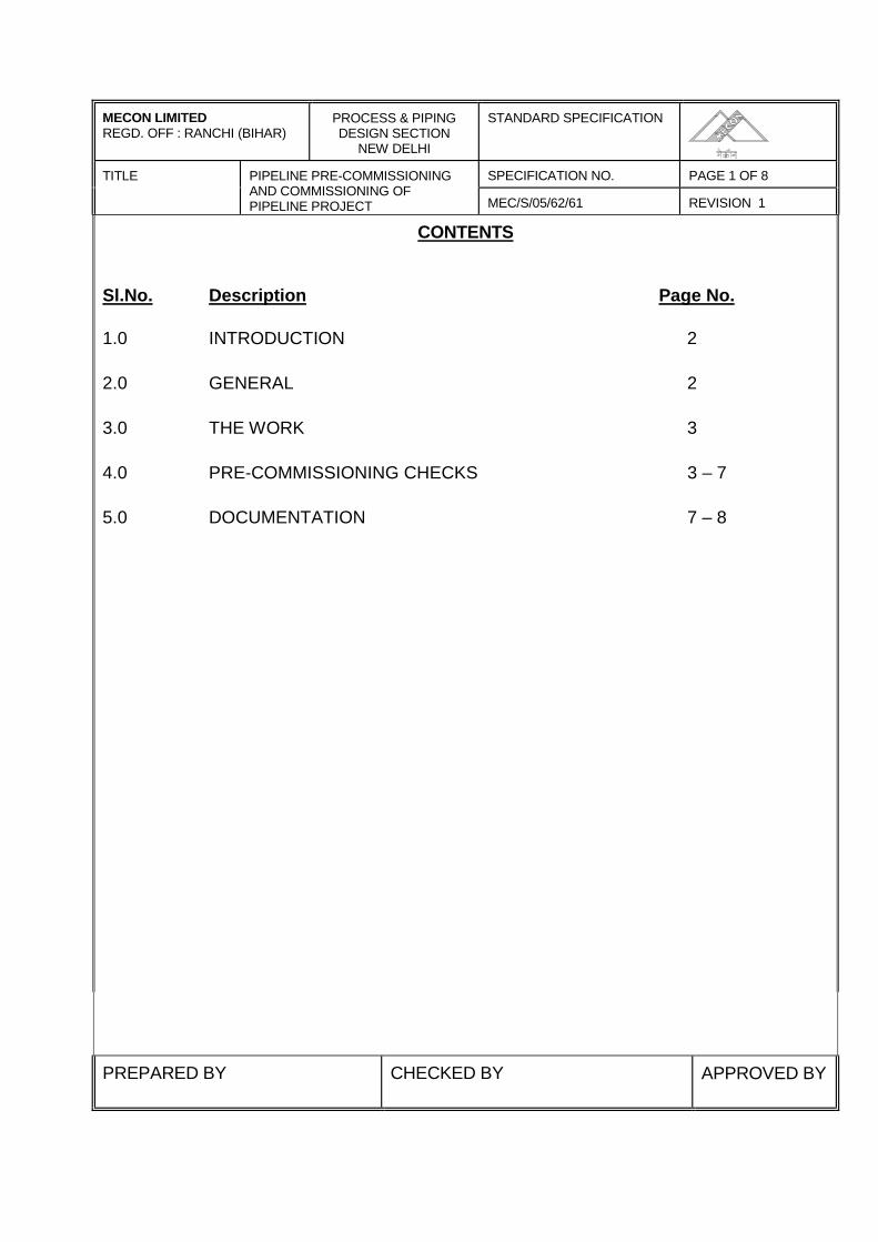
MECON LIMITEDREGD. OFF : RANCHI (BIHAR)
PROCESS & PIPINGDESIGN SECTION
NEW DELHI
STANDARD SPECIFICATION
SPECIFICATION NO. PAGE 1 OF 8TITLE PIPELINE PRE-COMMISSIONINGAND COMMISSIONING OFPIPELINE PROJECT MEC/S/05/62/61 REVISION 1
CONTENTS
Sl.No. Description Page No.
1.0 INTRODUCTION 2
2.0 GENERAL 2
3.0 THE WORK 3
4.0 PRE-COMMISSIONING CHECKS 3 – 7
5.0 DOCUMENTATION 7 – 8
PREPARED BY CHECKED BY APPROVED BY
MECON LIMITEDREGD. OFF : RANCHI (BIHAR)
PROCESS & PIPINGDESIGN SECTION
NEW DELHI
STANDARD SPECIFICATION
SPECIFICATION NO. PAGE 2 OF 8TITLE PIPELINE PRE-COMMISSIONINGAND COMMISSIONING OFPIPELINE PROJECT MEC/S/05/62/61 REVISION - 1
1.0 INTRODUCTION
This specification covers the minimum technical requirements for pre-commissioning and commissioning of gas pipeline, including pre-commissioning activities such as pre-commissioning checks, flushing ofterminal piping, dewatering, swabbing and nitrogen purging.
2.0 GENERAL
The scope of work for testing and commissioning including pre-commissioningactivities shall include, but not limited to the manpower, machinery &equipment, detailed procedures, materials and consumables, communicationsetc. to perform the work satisfactorily.
Contractor shall prepare detailed procedures for flushing of terminal piping,dewatering, swabbing, inertisation and commissioning of the pipeline, coveringall aspects of work for company’s approval. This shall include, but not limitedto, the sequence and description of all operations, data on materials,equipment, instruments, consumables, communications systems, necessarycalculations, detailed time schedule and organisation chart.
The Contractor shall be responsible for demonstrating the successfulcompletion of all the activities i.e. flushing of terminal piping, dewatering,swabbing, inertisation and commissioning of the pipeline. All necessary workto perform the job successfully including necessary modifications required shallbe the responsibility of the Contractor.
Contractor shall design and supply all temporary line connections, valves,instruments, etc. as required during the various operations.
In the event of any detail which is not fully addressed, it is warranted byContractor that work shall be performed in accordance with company’sspecification and the best recognised practices in the on-shore pipelineindustry.

MECON LIMITEDREGD. OFF : RANCHI (BIHAR)
PROCESS & PIPINGDESIGN SECTION
NEW DELHI
STANDARD SPECIFICATION
SPECIFICATION NO. PAGE 3 OF 8TITLE PIPELINE PRE-COMMISSIONINGAND COMMISSIONING OFPIPELINE PROJECT MEC/S/05/62/61 REVISION – 1
3.0 THE WORK
The work to be performed by the Contractor shall consist of the followingactivities :
Pre-commissioning : Entire pipeline project shall be checked with respectto latest P&ID’s and other design specification.
Dewatering : Removal of hydrotest water from the entire pipelinenetwork system.
Swabbing : Reducing the amount of remaining water in themain pipeline system which is left behind aftercompletion of the dewatering operations to makethe pipeline free of water.
Inertisation : Inertising the entire pipeline with nitrogen.
Commissioning : Charging the entire pipeline network with theproduct and achieving normal operating conditionsof the pipeline.
4.0 PRE-COMMISSIONING CHECKS
4.1 The pre-commissioning checks shall be carried out for the pipeline to ascertainthat the pipeline system has been mechanically completed in all respects.These checks shall cover the main pipeline including distribution networksystem and sectionalising valve stations. The pre-commissioning checks shallinclude the following:
i) System Checks
The entire facilities shall be checked against the latest P&ID’s and otherdesign specification codes.
MECON LIMITEDREGD. OFF : RANCHI (BIHAR)
PROCESS & PIPINGDESIGN SECTION
NEW DELHI
STANDARD SPECIFICATION
SPECIFICATION NO. PAGE 4 OF 8TITLE PIPELINE PRE-COMMISSIONINGAND COMMISSIONING OFPIPELINE PROJECT MEC/S/05/62/61 REVISION - 1
ii) Checking of Field Instruments
All the field instruments like control valves, sectionalising valves,transmitters, solenoid valves, shut down switches, alarms etc. shall bechecked physically and also for their intended application by simulatingthe operating conditions. It will also include checking of differentmeters, gauges action of shutdown valves etc. as applicable.
iii) Survey of the Pipelines
This shall be performed to confirm that proper fittings/ supports, routemarkets, fencing around SV Stations etc. have been intalled along thepipeline.
iv) Checking of Communications System
This is to check that there is proper communications with adequateback-up power to ensure uninterrupted communication.
v) Checking of Electrical Distribution System
This is to ensure safety and also to ensure an uninterrupted powersupply during startup and normal pipeline operation.
vi) Checking of Instruments, Controls & Interlocks
This is to check that instrument controls and interlocks are functional asper the normal operating conditions.
vii) Checking of Utilities
This is to check that utilities like power, nitrogen, UPS systeminstrument air, etc. are available prior to startup.
viii) Any other checks as may be considered necessary.
MECON LIMITEDREGD. OFF : RANCHI (BIHAR)
PROCESS & PIPINGDESIGN SECTION
NEW DELHI
STANDARD SPECIFICATION
SPECIFICATION NO. PAGE 5 OF 8TITLE PIPELINE PRE-COMMISSIONINGAND COMMISSIONING OFPIPELINE PROJECT MEC/S/05/62/61 REVISION - 1
4.2 DEWATERING
4.2.1 General
During the dewatering operation the major quantity of hydrotest water shall beremoved from the main pipeline and distribution network. It is the responsibilityof the Contractor to develop suitable dewatering procedure and submit forCompany’s approval.
The disposal of the water shall be performed such that no harm is done to theenvironment.
4.2.2 Operational Requirements
The dewatering operation shall consist of number of dewatering pig runs whenair is used as propellant for pig trains.
Bi-directional cup pigs shall be used and will be suitable for traversing theentire length of the pipeline/ pipe segment being dewatered. Contractor shallensure that all the pigs are designed to prevent damage to the pipeline internalcoating, if any.
The Contractor shall propose the minimum speed and the back pressure of thepigs in order that continuous operation will be performed without the pig gettingstuck. Contractor shall submit all the calculations regarding this procedure anda contingency plan for implementation in case the pigs get stuck.
Contractor shall provide a suitable compressor for oil-free air with sufficientcapacity and pressure.
Upon arrival of the pigs at the receiving end the Contractor in the presence ofCompany’s representative shall remove the pigs without delay.
MECON LIMITEDREGD. OFF : RANCHI (BIHAR)
PROCESS & PIPINGDESIGN SECTION
NEW DELHI
STANDARD SPECIFICATION
SPECIFICATION NO. PAGE 6 OF 8TITLE PIPELINE PRE-COMMISSIONINGAND COMMISSIONING OFPIPELINE PROJECT MEC/S/05/62/61 REVISION – 1
4.2.3 Acceptance Criteria
Before proceeding to the next stage of the inertisation operation Contractorshall ensure that bulk of the water has been removed from the pipeline.Contractor shall specify when the dewatering phase if finished and shall obtainapproval of the company before proceeding to the next inertisation phase.
4.3 Swabbing
4.3.1 General
The swabbing operation is meant to reduce the remaining water in the pipelineto bring the pipeline into touch dry condition.
Swabbing operation shall be carried out to ensure that there is no free waterleft inside the pipeline. This is done by driving number of swabbing pigs so thatthe weight increase in pig before and after the swabbing operation is not morethen 25%. The Contractor shall submit the detailed procedure along with theduration of the swabbing operation and obtain approval of the company beforestarting the operation.
4.3.2 Acceptance Criteria
The Contractor shall ensure that the swabbing operation is considered to becompleted when it is established that there is no free water left in the pipelineand the pipeline has achieved a touch dry condition. This shall be subject tocompany’s approval.
4.4 Inertisation
During the inertisation operation, the air left in the pipeline shall be replaced bynitrogen before admitting the product natural gas that the pipeline willultimately carry.
MECON LIMITEDREGD. OFF : RANCHI (BIHAR)
PROCESS & PIPINGDESIGN SECTION
NEW DELHI
STANDARD SPECIFICATION
SPECIFICATION NO. PAGE 7 OF 8TITLE PIPELINE PRE-COMMISSIONINGAND COMMISSIONING OFPIPELINE PROJECT MEC/S/05/62/61 REVISION - 1
The inertisation operation shall start as soon as possible after the swabbingoperation has been completed and approved by the company. Contractorshall submit the detailed purging procedure for approval for the company priorto its implementation.
Nitrogen needed for inertisation of the pipeline, shall be provided by theContractor. The maximum allowable oxygen content inside the pipeline shallbe less than 1% by volume.
Multiple separation pigs with nitrogen slugs in between shall be used forpipeline commissioning. At least three batches of nitrogen separated by fourseparation pigs shall be used for inertisation of the pipeline during charging ofgas in it. The combined nitrogen column length to be used for inertisationshould be at least 5% of the total pipeline length.
4.4.1 Safety Review before start of commissioning
A pre-startup safety review shall be carried out of the pipeline system beforepermitting entry of natural gas into the new facility. Owner/ Owner’srepresentative shall also participate in the pre-startup safety review.
4.5 COMMISSIONING
4.5.1 General
Commissioning of pipeline shall be considered completed when the line ischarged with product natural gas at operating pressure and the total systemoperated at normal operating parameters for a minimum period of 72 hourswith all the instruments, controls and interlocks working satisfactorily at normaloperating conditions. Contractor shall submit a detailed commissioningprocedure for company’s approval.
5.0 DOCUMENTATION
Contractor shall submit for approval of the company the complete description,detailed procedure and time schedule of all the dewatering, swabbing, purgingand commissioning operations, as applicable.
MECON LIMITEDREGD. OFF : RANCHI (BIHAR)
PROCESS & PIPINGDESIGN SECTION
NEW DELHI
STANDARD SPECIFICATION
SPECIFICATION NO. PAGE 8 OF 8TITLE PIPELINE PRE-COMMISSIONINGAND COMMISSIONING OFPIPELINE PROJECT MEC/S/05/62/61 REVISION - 1
Documents shall also contain all procedures and safety plans to be followedwhile carrying out the activities.
Upon successful completion of the work, Contractor shall prepare a final reportof the work which shall include necessary charts, diagrams, graphs,calculations, recordings, daily logs, measurements, details of the operation,etc. Report shall also include all certificates of calibration of instrumentsrequired together with records of calibration performed at site prior to the startof any operation.
5.1 Spares and Consumables
Supply of spares, tools and consumables for start-up & commissioning.
5.2 Safety
Follow the safety practice during execution of pre-commissioning/commissioning works as detailed in the scope of work. Maintain and follow allsafety practices equivalent or better than those being practiced for the pipelineduring pre-commissioning and commissioning.

SPECIFICATIONFOR
HEALTH, SAFETYAND
ENVIRONMENT (HSE)MANAGEMENT
SPECIFICATION NO. : MEC/S/05/62/65
(PROCESS & PIPELINE DESIGN SECTION)MECON LIMITED
DELHI - 110 092
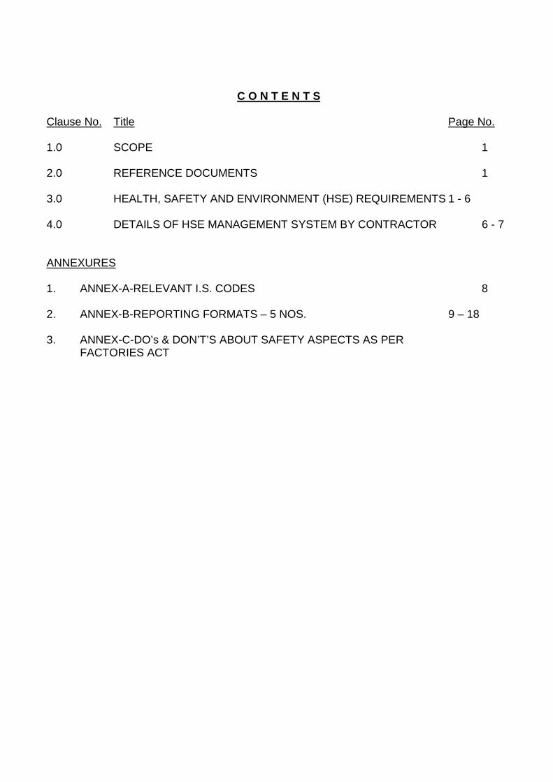
C O N T E N T S
Clause No. Title Page No.
1.0 SCOPE 1
2.0 REFERENCE DOCUMENTS 1
3.0 HEALTH, SAFETY AND ENVIRONMENT (HSE) REQUIREMENTS 1 - 6
4.0 DETAILS OF HSE MANAGEMENT SYSTEM BY CONTRACTOR 6 - 7
ANNEXURES
1. ANNEX-A-RELEVANT I.S. CODES 8
2. ANNEX-B-REPORTING FORMATS – 5 NOS. 9 – 18
3. ANNEX-C-DO’s & DON’T’S ABOUT SAFETY ASPECTS AS PER FACTORIES ACT
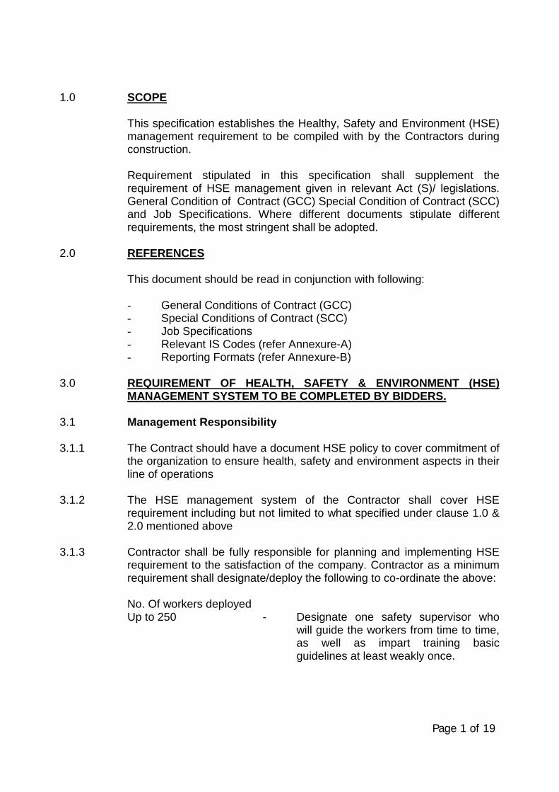
Page 1 of 19
1.0 SCOPE
This specification establishes the Healthy, Safety and Environment (HSE)management requirement to be compiled with by the Contractors duringconstruction.
Requirement stipulated in this specification shall supplement therequirement of HSE management given in relevant Act (S)/ legislations.General Condition of Contract (GCC) Special Condition of Contract (SCC)and Job Specifications. Where different documents stipulate differentrequirements, the most stringent shall be adopted.
2.0 REFERENCES
This document should be read in conjunction with following:
- General Conditions of Contract (GCC)- Special Conditions of Contract (SCC)- Job Specifications- Relevant IS Codes (refer Annexure-A)- Reporting Formats (refer Annexure-B)
3.0 REQUIREMENT OF HEALTH, SAFETY & ENVIRONMENT (HSE)MANAGEMENT SYSTEM TO BE COMPLETED BY BIDDERS.
3.1 Management Responsibility
3.1.1 The Contract should have a document HSE policy to cover commitment ofthe organization to ensure health, safety and environment aspects in theirline of operations
3.1.2 The HSE management system of the Contractor shall cover HSErequirement including but not limited to what specified under clause 1.0 &2.0 mentioned above
3.1.3 Contractor shall be fully responsible for planning and implementing HSErequirement to the satisfaction of the company. Contractor as a minimumrequirement shall designate/deploy the following to co-ordinate the above:
No. Of workers deployedUp to 250 - Designate one safety supervisor who
will guide the workers from time to time,as well as impart training basicguidelines at least weakly once.
Page 2 of 19
Above 250 & upto 500 - Deploy one qualified and experiencedsafety Engineer/ Officer who will guidethe workers from time to time as well asimpart basic guideline & training at leastweakly once.
Above 500 - One additional safety engineer/Officer(for every 500 or less) whose function will be as mentioned
above
Contractor shall indemnify and hold harmless GAIL/ MECON & theirrepresentative’s from any and all liabilities arising out of non fulfillment ofHSE requirements.
3.1.4 The Contractor shall ensure that the Health, Safety and Environment(HSE) requirements are clearly understood & faithfully implemented at alllevels, at each and every site/ work place.
3.1.5 The Contractor shall promote and develop consciousness for Healthy,Safety and Environment among all personnel working for the Contractor.Regular awareness programs and fabrication shop/work site meeting shallbe arranged on HSE activities to cover hazards involved in variousoperations during construction.
3.1.6 Arrange suitable first aid measures such as First Aid Box, trainedpersonnel to give First Aid, Stand by Ambulance or Vehicle and install fireprotection measures such as: adequate number of steel buckets with sandand water and adequate fire extinguishers to the satisfaction of GAIL/MECON.
3.1.7 The Contractor shall evolve a comprehensive planned and documentedsystem for implementation and monitoring of the HSE requirements. Thisshall submitted to GAIL & MECON for approval well in advance, prior tostart of work. The monitoring for implementation shall be done by regularinspection and compliance to the observations thereof. The Contractorshall get similar HSE requirements implemented at his sub-contractor (s)work site/ Office. However, compliance of HSE requirement shall be thesole responsibility of the Contractor. Any review/ approval by GAIL/MECON shall not absolve the Contractor of his responsibility/ liability inrelation to all HSE requirements.
3.1.8 Non-Conformance on HSE by the Contractor (including his Sub-contractors) as brought out during review/ audit by MECON/ OWNERrepresentative shall be resolved forthwith by Contractor. Compliancereport shall be possibility submitted to MECON/ GAIL at the earliest.
Page 3 of 19
3.1.9 The Contractor shall ensure participation of his Resident Engineer/Site-in-Charge in the Safety Committee/HSE Committee meetings arranged byGAIL/ MECON. The compliance of any observation shall be arrangedurgently. Contractor shall assist GAIL/MECON to achieve the targets setby them on HSE during the project implementation.
3.1.10 The Contractor shall adhere consistently to all provisions of HSErequirements. In case of non-compliance or continuous failure inimplementation of any of HSE provisions; GAIL/ MECON may imposestoppage of work without any Cost & Time implication to Owner and/orimpose a suitable penalty for non-compliance with a notice of suitableperiod, upto a cumulative limit of 1.0% (one percent) of Contract valuewith a ceiling of Rs. 10 lakhs. This penalty shall be in addition to all otherpenalties specified else where in the contract. The decision of imposingstoppage of work, its extent & monitory penalty shall rest withMECON/GAIL & binding on the Contractor.
3.1.11 All fatal accidents and other personnel accidents shall be investigated by ateam of Contractor’s senior personnel for root cause and recommendcorrective and preventive actions. Findings shall documented and suitableactions taken to avoid recurrences shall be communicated toGAIL/MECON. GAIL/MECON shall have the liberty to independentlyinvestigate such occurrences and Contractor shall extend all necessaryhelp and co-operation in this regard.
3.2 House Keeping
3.2.1 Contractor shall ensure that a high degree of house keeping is maintainedand shall ensure the followings:
a. All surplus earth and debris are removed/disposed off from theworking site to identified location (s).
b. Unused/Surplus Cables Steel items and steel scrap lying scatteredat different places within the working areas are removed toidentified location (s).
c. All wooden scrap, empty wooden cable drums and othercombustible packing materials shall be removed from work place toidentified location(s).
d. Roads shall be kept clear and materials like pipes, steel, sand,boulders, concrete chips and bricks, etc. shall not be allowed in theroads to obstructs free movement of men & machineries.
Page 4 of 19
e. Fabricated steel structurals, pipes & piping materials shall bestacked properly for erection.
f. Water logging on rods shall not be allowed.
g. No parking of trucks/ trolleys, cranes and trailors etc. shall beallowed on of roads, which may obstruct the traffic movements.
h. Utmost care shall be taken to ensure over all cleanliness andproper up keep of the working areas.
i. Trucks carrying sand, earth and pulverized materials etc. shall becovered while moving within the plant areas.
3.3 Healthy, Safety and Environment
a) The Contractor shall provide safe means of access to any workingplace including provision of suitable and sufficient scaffolding atvarious stages during all operations of the work for the safety of hisworkmen, and GAIL/ MECON. Contractor shall ensure deploymentof appropriate equipment and appliances for adequate safety andhealthy of the workmen and protection of surrounding areas.
b) The Contractor shall ensure that all their staff workers includingtheir sub-Contractor (s) shall wear Safety Helmet and Safety shoes.Contractor shall also ensure use of safety belt, protective goggles,gloves etc. by the personnel as per jobs requirements. All thesegadgets shall conform to relevant IS specification equivalent.
c) Contractor shall ensure that a proper Safety Net System shall beused at appropriate locations. The safety net shall be located notmore than 30 feet (9.0 metrs) below the working surface at site toarrest or to reduce the consequences of possible fall of personsworking at different heights.
d) Contractor shall ensure that flash back arrester shall used whileusing gas Cylinders at site. Cylinders shall be mounted on trollys.
e) The Contractor shall assign to his workmen, tasks commensuratewith their qualification, experience and state of health for driving ofvehicles, handling and erections of materials and equipment’s. Alllifting equipments shall be tested certified for its capacity beforeuse. Adequate and suitable lighting at every work place andapproach there to shall be provided by the contractor beforestarting the actual work/ operation at night..

Page 5 of 19
f) Hazardous and/or toxic material such as solvent coating or thinnersshall be stored in appropriate containers.
g) All hazardous materials shall be labeled with the name of thematerials, the hazards associated with its use and necessaryprecautions to be taken.
h) Contractor shall ensure that during the performance of the work allhazards to the health of personnel have been identified assessedand eliminated.
i) Chemical spills shall be contained & cleaned up immediately toprevent further contamination.
j) All personnel exposed to physical agents such as ionizing or non-ionizing radiation ultraviolet rays or similar other physical agentsshall be provided with adequate shielding or protectioncommensurate with type of exposure involved.
k) Where contract or exposure of hazardous materials could exceedlimits or could otherwise have harmful affects, appropriate personalprotective equipment’s such as gloves, goggles, aprons, chemicalresistant clothing and respirator shall be used
l) Contractor shall ensure the following facilities at work sites:
I) A Crèche where 10 or more female workers are havingchildren below the age of 6 years.
II) Reasonable Canteen facilities are made available atappropriate location depending upon site conditions.
m) Suitable facilities for toilet, drinking water, proper lighting shall beprovided at site and labor camps, commensurate with applicableLaws/Legislation.
n) Contractor shall ensure storage and utilization methodology ofmaterial that are not detrimental to the environment. Whereverrequired Contractor shall ensure that only the environment friendlymaterial are selected.
o) All person deployed at site shall be knowledgeable of and complywith the environmental laws, rules & regulation relating to thehazardous materials substance and wastes. Contractor shall notdump, release or otherwise discharge or dispose off any suchmaterials without the authorization of GAIL/ MECON.
Page 6 of 19
4.0 DETAILS OF HSE MANAGEMENT SYSTEM BY CONTRACTOR
4.1 On Awards of Contract
The Contractor shall prior to start of work submit his Health. Safety andEnvironment Manual of procedure and HSE Plans for approval byGAIL/MECON. The Contractor shall participate in the pre-start meetingwith GAIL/MECON to finalize HSE plans including the following.
- Job procedure to be followed by Contractor for activities coveringHandling of equipment’s, Scaffolding, Electric Installation,describing the risks involved, actions to be taken and methodologyfor monitoring each.
- Organizations structure alongwith responsibility and authorityrecords/ reports etc. on HSE activities.
4.2 During job execution
4.2.1 Implement approved Health, Safety and Environment managementprocedure including but not limited to as brought our under para 3.0.Contractor shall also ensure to:
- Arrange workmen compensation insurance, registration under ESIAct, third party liability insurance etc. as applicable.
- Arrange all HSE permits before start of activities (as applicable) likeher work, confined space, work at heights, storage ofChemicals/explosives materials and its use and implement allprecautions mentioned therein
- Submit timely the completed check list on HSE activities, MonthlyHSE report, accident report, investigation report, etc. as perGAIL/MECON requirements. Compliance of instructions on HSEshall be done by Contractor and informed urgently toGAIL/MECON.
- Ensure that resident Engineers/Site-In-Charge of the Contractorshall amend all the Safety Committee/HSE meeting arranged byGAIL/ MECON only in case of his absence from site, a secondssenior most person shall be nominated by him in advance andcommunicated to GAIL/MECON.
- Display at site office and work locations caution boards, list ofhospitals for emergency services available.
Page 7 of 19
- Provided posters, banners, for safe working to promote safetyconsciousness
- Carryout audits/inspection at sub Contractor work as per approvedHSE documents & submit the reports for GAIL/MECON review.
- Assistk in HSE audits by GAIL/ MECON and submit compliancereport.
- Generate & submit HSE records/ reports as per HSE Plan.
- Appraise GAIL/MECON on HSE activities at site.
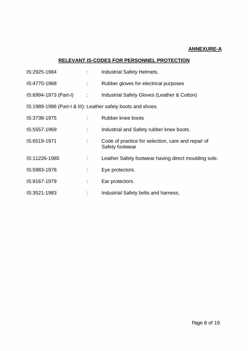
Page 8 of 19
ANNEXURE-A
RELEVANT IS-CODES FOR PERSONNEL PROTECTION
IS:2925-1984 : Industrial Safety Helmets.
IS:4770-1968 : Rubber gloves for electrical purposes
IS:6994-1973 (Part-I) : Industrial Safety Gloves (Leather & Cotton)
IS:1989-1986 (Part-I & III): Leather safety boots and shoes.
IS:3738-1975 : Rubber knee boots
IS:5557-1969 : Industrial and Safety rubber knee boots.
IS:6519-1971 : Code of practice for selection, care and repair ofSafety footwear
IS:11226-1985 : Leather Safety footwear having direct moulding sole.
IS:5983-1978 : Eye protectors.
IS:9167-1979 : Ear protectors.
IS:3521-1983 : Industrial Safety belts and harness.
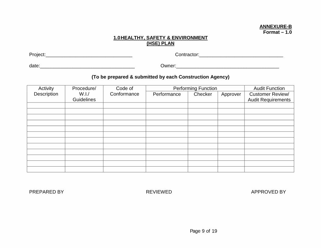
Page 9 of 19
ANNEXURE-BFormat – 1.0
1.0 HEALTHY, SAFETY & ENVIRONMENT(HSE) PLAN
Project:________________________________ Contractor:_______________________________
date:___________________________________ Owner:______________________________________
(To be prepared & submitted by each Construction Agency)
Performing Function Audit FunctionActivityDescription
Procedure/W.I./
Guidelines
Code ofConformance Performance Checker Approver Customer Review/
Audit Requirements
PREPARED BY REVIEWED APPROVED BY

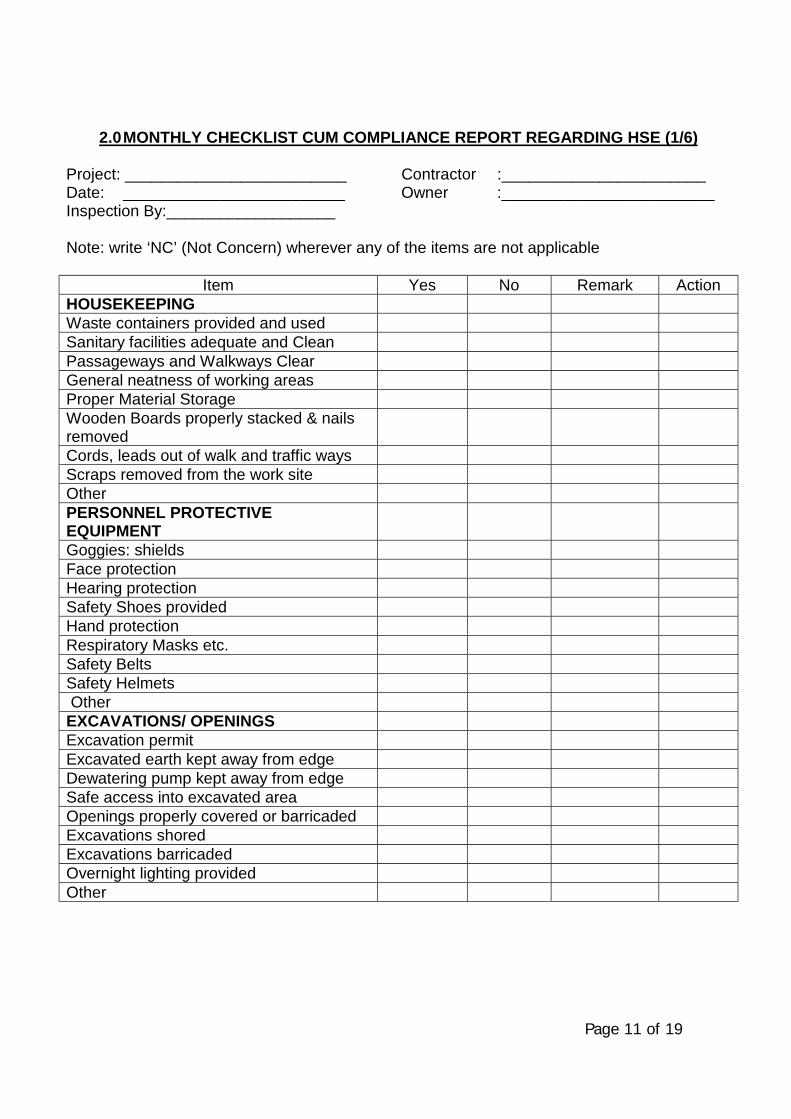
Page 11 of 19
2.0 MONTHLY CHECKLIST CUM COMPLIANCE REPORT REGARDING HSE (1/6)
Project: _________________________ Contractor :_______________________Date: _________________________ Owner :________________________Inspection By:___________________
Note: write ‘NC’ (Not Concern) wherever any of the items are not applicable
Item Yes No Remark ActionHOUSEKEEPINGWaste containers provided and usedSanitary facilities adequate and CleanPassageways and Walkways ClearGeneral neatness of working areasProper Material StorageWooden Boards properly stacked & nailsremovedCords, leads out of walk and traffic waysScraps removed from the work siteOtherPERSONNEL PROTECTIVEEQUIPMENTGoggies: shieldsFace protectionHearing protectionSafety Shoes providedHand protectionRespiratory Masks etc.Safety BeltsSafety Helmets OtherEXCAVATIONS/ OPENINGSExcavation permitExcavated earth kept away from edgeDewatering pump kept away from edgeSafe access into excavated areaOpenings properly covered or barricadedExcavations shoredExcavations barricadedOvernight lighting providedOther
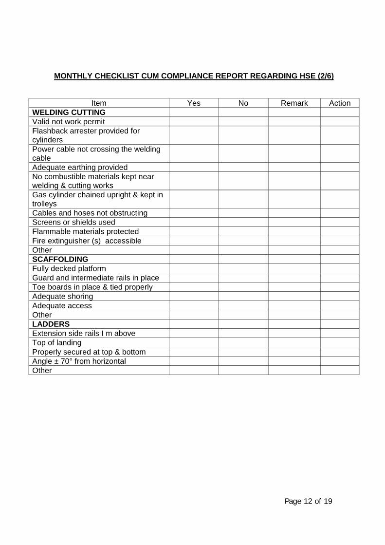
Page 12 of 19
MONTHLY CHECKLIST CUM COMPLIANCE REPORT REGARDING HSE (2/6)
Item Yes No Remark ActionWELDING CUTTINGValid not work permitFlashback arrester provided forcylindersPower cable not crossing the weldingcableAdequate earthing providedNo combustible materials kept nearwelding & cutting worksGas cylinder chained upright & kept introlleysCables and hoses not obstructingScreens or shields usedFlammable materials protectedFire extinguisher (s) accessibleOtherSCAFFOLDINGFully decked platformGuard and intermediate rails in placeToe boards in place & tied properlyAdequate shoringAdequate accessOtherLADDERSExtension side rails I m aboveTop of landingProperly secured at top & bottomAngle ± 70° from horizontalOther
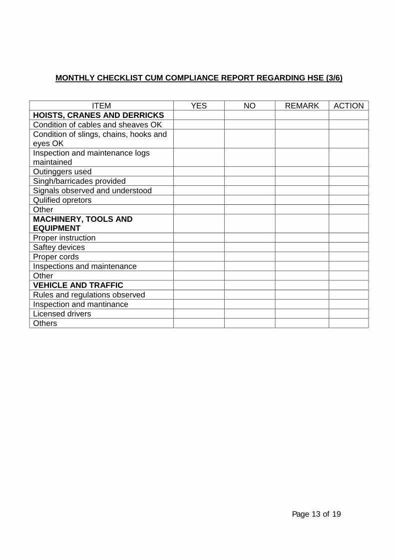
Page 13 of 19
MONTHLY CHECKLIST CUM COMPLIANCE REPORT REGARDING HSE (3/6)
ITEM YES NO REMARK ACTIONHOISTS, CRANES AND DERRICKSCondition of cables and sheaves OKCondition of slings, chains, hooks andeyes OKInspection and maintenance logsmaintainedOutinggers usedSingh/barricades providedSignals observed and understoodQulified opretorsOtherMACHINERY, TOOLS ANDEQUIPMENTProper instructionSaftey devicesProper cordsInspections and maintenanceOtherVEHICLE AND TRAFFICRules and regulations observedInspection and mantinanceLicensed driversOthers
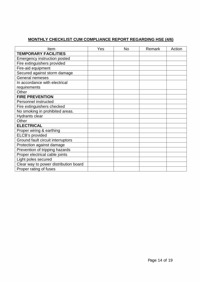
Page 14 of 19
MONTHLY CHECKLIST CUM COMPLIANCE REPORT REGARDING HSE (4/6)
Item Yes No Remark ActionTEMPORARY FACILITIESEmergency instruction postedFire extinguishers providedFire-aid equipmentSecured against storm damageGeneral nemesesIn accordance with electricalrequirementsOtherFIRE PREVENTIONPersonnel instructedFire extinguishers checkedNo smoking in prohibited areas.Hydrants clearOtherELECTRICALProper wiring & earthingELCB’s providedGround fault circuit interruptorsProtection against damagePrevention of tripping hazardsProper electrical cable jointsLight poles securedClear way to power distribution boardProper rating of fuses
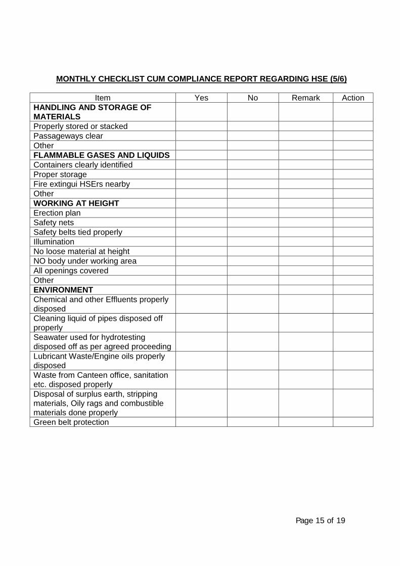
Page 15 of 19
MONTHLY CHECKLIST CUM COMPLIANCE REPORT REGARDING HSE (5/6)
Item Yes No Remark ActionHANDLING AND STORAGE OFMATERIALSProperly stored or stackedPassageways clearOtherFLAMMABLE GASES AND LIQUIDSContainers clearly identifiedProper storageFire extingui HSErs nearbyOtherWORKING AT HEIGHTErection planSafety netsSafety belts tied properlyIlluminationNo loose material at heightNO body under working areaAll openings coveredOtherENVIRONMENTChemical and other Effluents properlydisposedCleaning liquid of pipes disposed offproperlySeawater used for hydrotestingdisposed off as per agreed proceedingLubricant Waste/Engine oils properlydisposedWaste from Canteen office, sanitationetc. disposed properlyDisposal of surplus earth, strippingmaterials, Oily rags and combustiblematerials done properlyGreen belt protection
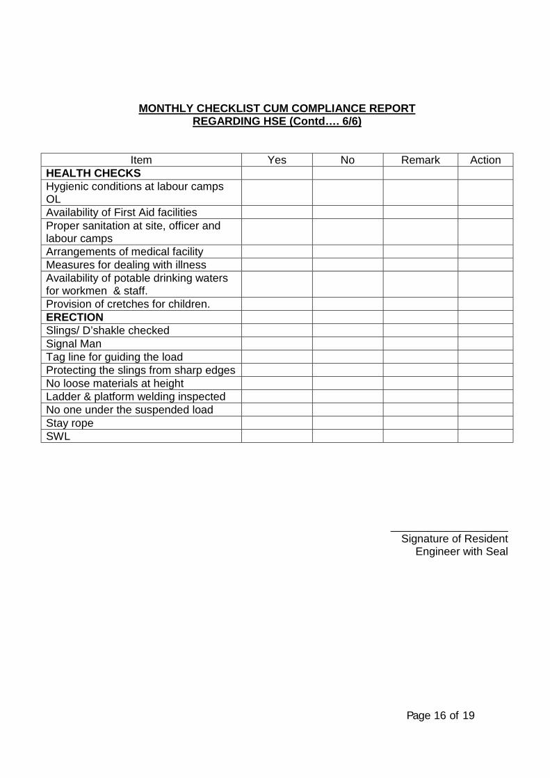
Page 16 of 19
MONTHLY CHECKLIST CUM COMPLIANCE REPORTREGARDING HSE (Contd…. 6/6)
Item Yes No Remark ActionHEALTH CHECKSHygienic conditions at labour campsOLAvailability of First Aid facilitiesProper sanitation at site, officer andlabour campsArrangements of medical facilityMeasures for dealing with illnessAvailability of potable drinking watersfor workmen & staff.Provision of cretches for children.ERECTIONSlings/ D’shakle checkedSignal ManTag line for guiding the loadProtecting the slings from sharp edgesNo loose materials at heightLadder & platform welding inspectedNo one under the suspended loadStay ropeSWL
___________________Signature of Resident
Engineer with Seal
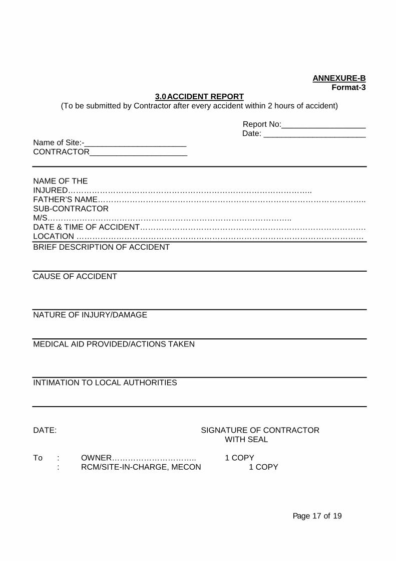
Page 17 of 19
ANNEXURE-BFormat-3
3.0 ACCIDENT REPORT(To be submitted by Contractor after every accident within 2 hours of accident)
Report No:___________________Date: _______________________
Name of Site:-_______________________CONTRACTOR______________________
NAME OF THEINJURED………………………………………………………………………………..FATHER’S NAME………………………………………………………………………………………..SUB-CONTRACTORM/S………………………………………………………………………………..DATE & TIME OF ACCIDENT………………………………………………………………………….LOCATION ………………………………………………………………………………………………BRIEF DESCRIPTION OF ACCIDENT
CAUSE OF ACCIDENT
NATURE OF INJURY/DAMAGE
MEDICAL AID PROVIDED/ACTIONS TAKEN
INTIMATION TO LOCAL AUTHORITIES
DATE: SIGNATURE OF CONTRACTORWITH SEAL
To : OWNER………………………….. 1 COPY: RCM/SITE-IN-CHARGE, MECON 1 COPY
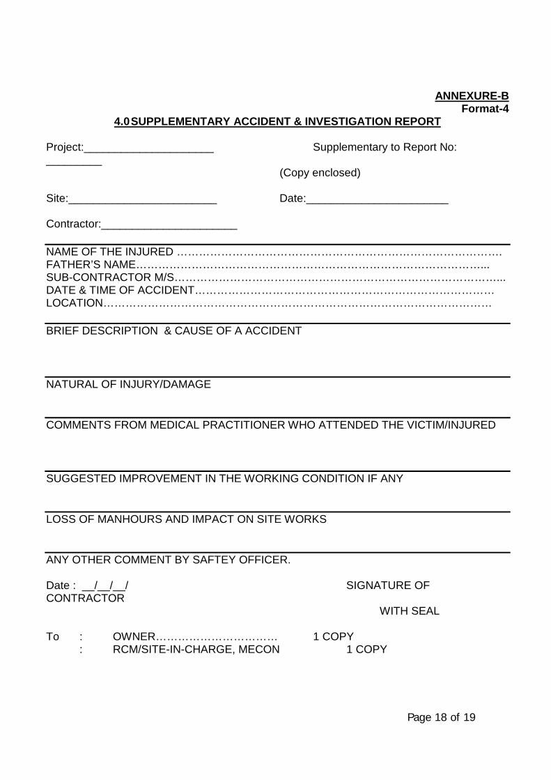
Page 18 of 19
ANNEXURE-BFormat-4
4.0 SUPPLEMENTARY ACCIDENT & INVESTIGATION REPORT
Project:_____________________ Supplementary to Report No:_________
(Copy enclosed)
Site:________________________ Date:_______________________
Contractor:______________________
NAME OF THE INJURED …………………………………………………………………………….FATHER’S NAME…………………………………………………………………………………...SUB-CONTRACTOR M/S……………………………………………………………………………...DATE & TIME OF ACCIDENT………………………………………………………………………LOCATION……………………………………………………………………………………………
BRIEF DESCRIPTION & CAUSE OF A ACCIDENT
NATURAL OF INJURY/DAMAGE
COMMENTS FROM MEDICAL PRACTITIONER WHO ATTENDED THE VICTIM/INJURED
SUGGESTED IMPROVEMENT IN THE WORKING CONDITION IF ANY
LOSS OF MANHOURS AND IMPACT ON SITE WORKS
ANY OTHER COMMENT BY SAFTEY OFFICER.
Date : __/__/__/ SIGNATURE OFCONTRACTOR
WITH SEAL
To : OWNER…………………………… 1 COPY: RCM/SITE-IN-CHARGE, MECON 1 COPY
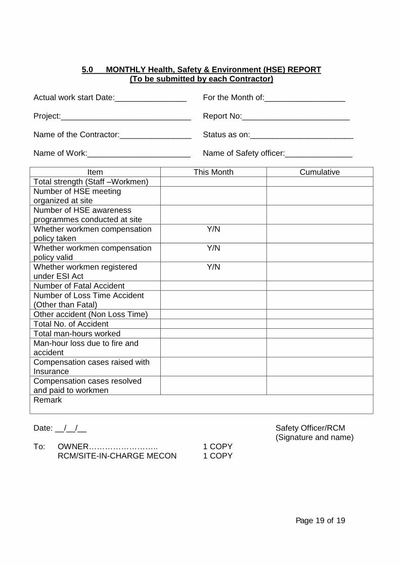
Page 19 of 19
5.0 MONTHLY Health, Safety & Environment (HSE) REPORT(To be submitted by each Contractor)
Actual work start Date:________________ For the Month of:__________________
Project:_____________________________ Report No:________________________
Name of the Contractor:________________ Status as on:_______________________
Name of Work:_______________________ Name of Safety officer:_______________
Item This Month CumulativeTotal strength (Staff –Workmen)Number of HSE meetingorganized at siteNumber of HSE awarenessprogrammes conducted at siteWhether workmen compensationpolicy taken
Y/N
Whether workmen compensationpolicy valid
Y/N
Whether workmen registeredunder ESI Act
Y/N
Number of Fatal AccidentNumber of Loss Time Accident(Other than Fatal)Other accident (Non Loss Time)Total No. of AccidentTotal man-hours workedMan-hour loss due to fire andaccidentCompensation cases raised withInsuranceCompensation cases resolvedand paid to workmenRemark
Date: __/__/__ Safety Officer/RCM(Signature and name)
To: OWNER…………………….. 1 COPY RCM/SITE-IN-CHARGE MECON 1 COPY
\\Akjha\work contrac\standard TS for Pipe Line WC (Vol-II) MASTER FOLDER\66 quality assurance system\Specification - Quality Assurance Plan - Reqd. - 66.doc
SPECIFICATIONFOR
QUALITY ASSURANCE SYSTEMSREQUIREMENTS
SPECIFICATION NO. MEC/S/05/62/66
(PROCESS & PIPELINE DESIGN SECTION)
MECON LIMITEDDELHI - 110 092
\\Akjha\work contrac\standard TS for Pipe Line WC (Vol-II) MASTER FOLDER\66 quality assurance system\Specification - Quality Assurance Plan - Reqd. - 66.doc
MECON LIMITEDREGD. OFF : RANCHI (BIHAR)
PROCESS & PIPINGDESIGN SECTION
NEW DELHI
STANDARD SPECIFICATION
SPECIFICATION NO. PAGE 1 OF 9TITLE QUALITY ASSURANCE SYSTEMS
REQUIREMENTS MEC/S/05/62/66 REVISION 0
CONTENTS
Sl.No. Description Page No.
1.0 INTRODUCTION 1
2.0 DEFINITIONS 1 - 2
3.0 CONTRACTORS SCOPE OF WORK 2 - 4
4.0 QUALITY ASSURANCE REQUIREMENTS 4 - 7
ATTACHMENTS
TITLE NUMBER
FORMAT FOR QUALITY PLAN FORMAT 00001
FORMAT FOR OBSERVATION ON FORMAT 00002
PREPARED BY CHECKED BY APPROVED BY
\\Akjha\work contrac\standard TS for Pipe Line WC (Vol-II) MASTER FOLDER\66 quality assurance system\Specification - Quality Assurance Plan - Reqd. - 66.doc
MECON LIMITEDREGD. OFF : RANCHI (BIHAR)
PROCESS & PIPINGDESIGN SECTION
NEW DELHI
STANDARD SPECIFICATION
SPECIFICATION NO. PAGE 2 OF 9TITLE QUALITY ASSURANCE SYSTEMS
REQUIREMENTS MEC/S/05/62/66 REVISION 0
1.0 INTRODUCTION
This specification establishes the Quality Assurance Requirements to be met bythe sub-contractors (including turnkey Contractors) and their sub-vendors.
In case of any conflict between this specification and other provisions of thecontract/ purchase order, the same shall be brought to the notice of MECON,at the stage of bidding and shall be resolved with MECON, prior to theplacement of order.
2.0 DEFINITION
Bidder
For the purpose of this specification, the word “Bidder” means the person(s),firm, company or organisation who is under the process of being contracted byMECON/ Owner for delivery of some products (including service). The word isconsidered synonymous to supplier, contractor or vendor.
Correction
Action taken to eliminate the detected non-conformity.
Refers to repair, rework or adjustment and relates to the disposition of anexisting non-conformity.
Corrective Action
Action taken to eliminate the causes of an existing non-conformity, defect orother undesirable situation in order to prevent recurrence.
Preventive Action
Action taken to eliminate the causes of a potential non-conformity, defect orother undesirable situation in order to prevent its recurrence.
Process
Set of inter-related resources and activities which transform inputs intooutputs.
\\Akjha\work contrac\standard TS for Pipe Line WC (Vol-II) MASTER FOLDER\66 quality assurance system\Specification - Quality Assurance Plan - Reqd. - 66.doc
MECON LIMITEDREGD. OFF : RANCHI (BIHAR)
PROCESS & PIPINGDESIGN SECTION
NEW DELHI
STANDARD SPECIFICATION
SPECIFICATION NO. PAGE 3 OF 9TITLE QUALITY ASSURANCE SYSTEMS
REQUIREMENTS MEC/S/05/62/66 REVISION 0Special Process
Processes requiring pre-qualification of their process capability.
3.0 CONTRACTORS SCOPE OF WORK
3.1 Prior to award of contract
The bidder shall understand scope of work, drawings, specifications andstandards etc., attached to the tender/ enquiry document, before he makes anoffer.
The bidder shall submit milestone chart showing the time required for eachmilestone activity and linkages between different milestone activities alongwithoverall time period required to complete the entire scope of work.
The bidder shall develop and submit manpower and resource deploymentchart.
The bidder shall submit, alongwith the bid, a manual or equivalent documentdescribing/ indicating/ addressing various control/ check points for the purposeof quality assurance and the responsibilities of various functions responsiblefor quality assurance.
3.2 After the award of contract
The bidder shall submit the schedule for submission of following documents inthe kick-off meeting or within two weeks of the placement of order, whicheveris earlier.
• Detailed Bar Chart• Quality plan for all activities, required to be done by the bidder, to
accomplish offered scope of work.• Inspection and test plans, covering various control aspects.• Job procedures as required by MECON/ Owner.• Procurement schedule for items to be supplied by contractor covering
inspection of the same.
Various documents submitted by the bidder shall be finalised in consultationwith MECON. Here it shall be presumed that ones a bidder has made an offer,he has understood the requirements given in this specification and agrees to
\\Akjha\work contrac\standard TS for Pipe Line WC (Vol-II) MASTER FOLDER\66 quality assurance system\Specification - Quality Assurance Plan - Reqd. - 66.doc
MECON LIMITEDREGD. OFF : RANCHI (BIHAR)
PROCESS & PIPINGDESIGN SECTION
NEW DELHI
STANDARD SPECIFICATION
SPECIFICATION NO. PAGE 4 OF 9TITLE QUALITY ASSURANCE SYSTEMS
REQUIREMENTS MEC/S/05/62/66 REVISION 0
comply with them in totality unless otherwise categorically so indicated duringpre-award stage through agreed deviation/ exception request. All QualityAssurance Plan (QAP) documents shall be reviewed by concerned functionalgroups of MECON and the bidder shall be required to incorporate all commentswithin the framework of this specification at this stage of the contract. It isalso obligatory on the part of the bidder that obtains approval on every QualityAssurance Plan (QAP) documents, before he starts using a particular documentfor delivery of contracted scope of work. Participation of MECON/ Owner inreview/ approval of quality plan/ QAP documents does not absolve thecontractor of his contractual obligations towards specified and intended use ofthe product (or service) provided/ to be provided by him under the contract.
3.3 During job execution
During job execution, the bidder shall fully comply with all quality documentsubmitted and finalised/ agreed against the requirements of this specification.Approval of MECON on all these documents shall be sought before start ofwork.
Bidder shall produce sufficient quality records on controlled/ agreed formssuch that requirements given in this specification are objectively/demonstrable.
Bidder shall facilitate MECON/ Owner during quality/ technical audits at hisworks/ sites.
Bidder shall discharge all responsibilities towards enforcement of thisspecification on all his sub-contractors for any part of the scope which is sub-contracted.
4.0 QUALITY ASSURANCE SYSTEM REQUIREMENTS
4.1 The bidder shall nominate an overall incharge of the contract titled as “ProjectManager” for the scope of work of agreed contract. The name of this personshall be duly intimated to MECON including all subsequent changes, if any.MECON shall correspond only with the project manager of the bidder on allmatters of the project. The project manager of the bidder shall be responsiblefor co-ordination and management of activities with bidder’s organisation andall sub-vendors appointed by the bidder.
\\Akjha\work contrac\standard TS for Pipe Line WC (Vol-II) MASTER FOLDER\66 quality assurance system\Specification - Quality Assurance Plan - Reqd. - 66.doc
MECON LIMITEDREGD. OFF : RANCHI (BIHAR)
PROCESS & PIPINGDESIGN SECTION
NEW DELHI
STANDARD SPECIFICATION
SPECIFICATION NO. PAGE 5 OF 9TITLE QUALITY ASSURANCE SYSTEMS
REQUIREMENTS MEC/S/05/62/66 REVISION 0
After award of work, the bidder may review augmentation of manpower andresources deployment chart (submitted earlier), detail it out, if so consentedby MECON/ Owner and resubmit the same as “issued for effectiveimplementation of the project”.
4.2 The bidder shall plan the contract scope of work on quality plan format suchthat no major variation is expected during delivery of contract scope of work.These quality plan shall be made on enclosed format complete in all respect.The quality plan shall be assumed to be detailing bidder’s understanding andplanning for the contract/ offered scope of work. The bidder shall plan thetype of resources including various work methodology which he agrees toutilize for delivery of contract scope of work.
4.3 The bidder is required to review the contract at all appropriate stages toevaluate his capabilities with respect to timely and quality completion of allactivities pertaining to contracted scope of work and shall report forconstraints, if any to MECON/ Owner.
4.4 The design activities, if any, performed during delivery of contract scope ofwork shall be so controlled that the outputs is reliable enough. It is expectedthat during development of design, the bidder shall take recourse to detailedchecking, inter departmental reviews and documented verification methods.
4.5 For all documents which the bidder is likely to utilise for delivery of contractscope of work, a system must exist which assures that latest/ requiredversion(s) of the document(s) is available at all location/ point of use.
4.6 In case the bidder decides to sub-contract any part/ full of the contract scopeof work (without prejudice to main Contractual condition), the bidder shall :
• Evaluate the technical and financial capabilities and past performance ofthe sub-contractor(s) and their products and/ or services beforeawarding them with the sub-contracted scope of work. Selection of asub-contractor should meet MECON approval in documented form.
• Requirement of this specification shall be enforced on sub-contractedagency also. The bidder shall choose sub-contractor based on theircapability to meet requirements of this specification also.
\\Akjha\work contrac\standard TS for Pipe Line WC (Vol-II) MASTER FOLDER\66 quality assurance system\Specification - Quality Assurance Plan - Reqd. - 66.doc
MECON LIMITEDREGD. OFF : RANCHI (BIHAR)
PROCESS & PIPINGDESIGN SECTION
NEW DELHI
STANDARD SPECIFICATION
SPECIFICATION NO. PAGE 6 OF 9TITLE QUALITY ASSURANCE SYSTEMS
REQUIREMENTS MEC/S/05/62/66 REVISION 0
Note: It may so happen that, in a given situation, a sub-contractor may nothave a system meeting the requirements of this specification. In allsuch eventualities, bidder may lend his system to sub-contractor for thecontract such that sub-contractor effectively meets the requirements ofthis specification. In all such cases MECON shall be duly informed.
4.7 Bidder shall establish adequate methodology such that the materials suppliedby the Owner/ MECON shall be adequately preserved, handled and made useof for the purpose for which they are provided.
4.8 All output delivered against contract scope of work shall be suitably identifiedin such a manner that either through identification or some other means,sufficient traceability is maintained which permits effective resolution of anyproblem reported in the outputs.
4.9 Critical activities shall be identified and the bidder is required to havedocumented methodologies which he is going to utilize for carrying out suchactivities under the contract scope of work. Wherever it is difficult to fullyinspect or verify the output (special process), bidder shall pre-qualify, theperformers and methodologies.
4.10 All inspections carried out by the bidder’s surveillance/ inspection staff shall beconformity to quality plans and/ or inspection and test plans. All inspectionresults shall be duly documented on controlled/ agreed forms such that resultscan be co-related to specific product, that was inspected/ tested.
4.11 All inspection, measuring & test equipments (IMTEs) shall be duly calibrated asper National/ International standards/ codes and only calibrated and certifiedIMTEs shall be utilized for delivery of contract scope of work.
4.12 All outputs/ products delivered against contract scope of work shall be dulymarked such that their inspection status is clearly evident during all stages/period of the contract.
4.13 All non-conformities (NCs) found by the contractor’s inspection/ surveillancestaff shall be duly recorded, including their disposal action. The deficienciesobserved during stage of the product, shall be recorded and resolved suitably.Effective corrective and preventive action shall be implemented by the bidderfor all repetitive NCs, including deficiencies.
\\Akjha\work contrac\standard TS for Pipe Line WC (Vol-II) MASTER FOLDER\66 quality assurance system\Specification - Quality Assurance Plan - Reqd. - 66.doc
MECON LIMITEDREGD. OFF : RANCHI (BIHAR)
PROCESS & PIPINGDESIGN SECTION
NEW DELHI
STANDARD SPECIFICATION
SPECIFICATION NO. PAGE 7 OF 9TITLE QUALITY ASSURANCE SYSTEMS
REQUIREMENTS MEC/S/05/62/66 REVISION 0
4.14 All deficiencies noticed by MECON/ Owner representative(s) shall be recordedon a controlled form (Format No. 00002). Such deficiencies shall be analysedby the bidder and effective and appropriate correction, corrective andpreventive actions shall be implemented. Bidder shall intimate MECON/ Ownerof all such corrective and preventive action implemented by him.
4.15 Bidder shall establish appropriate methodologies for safe and effectivehandling, storage, preservation of various materials/ inputs encounteredduring delivery of contract scope of work.
4.16 Bidder shall prepare sufficient records for various processes carried out by himfor delivery of contract scope of work such that requirements of thisspecification are objectively demonstrable. In case MECON/ Owner finds thatenough objective evidence/ recording is not available for any particularprocess, bidder shall be obliged to make additional records so as to providesufficient objective evidence. The decision of MECON/ Owner shall be finaland binding on such issues.
4.17 The bidder shall arrange internal quality audits at quarterly intervals, toindependently assess the conformance by various performers to therequirements of this specification. The findings of such assessment shall beduly recorded and a copy shall be sent to MECON/ Owner for review.
4.18 For all special processes, bidder shall deploy only qualified performers.Wherever MECON/ Owner observes any deficiency, the bidder shall arrangethe adequate training to the performer(s) before any further delivery of work.
\\Akjha\work contrac\standard TS for Pipe Line WC (Vol-II) MASTER FOLDER\66 quality assurance system\Specification - Quality Assurance Plan - Reqd. - 66.doc
MECON LIMITEDREGD. OFF : RANCHI (BIHAR)
PROCESS & PIPINGDESIGN SECTION
NEW DELHI
STANDARD SPECIFICATION
SPECIFICATION NO. PAGE 8 OF 9TITLE QUALITY ASSURANCE SYSTEMS
REQUIREMENTS MEC/S/05/62/66 REVISION 0
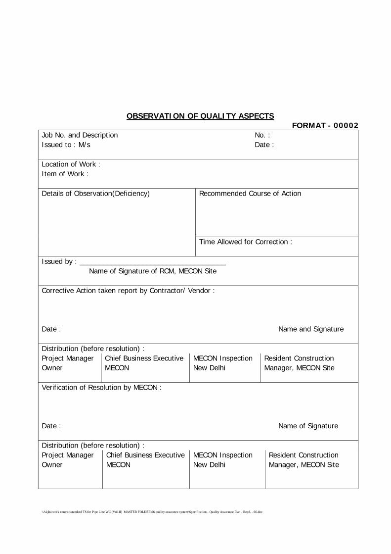
\\Akjha\work contrac\standard TS for Pipe Line WC (Vol-II) MASTER FOLDER\66 quality assurance system\Specification - Quality Assurance Plan - Reqd. - 66.doc
OBSERVATION OF QUALITY ASPECTSFORMAT - 00002
Job No. and Description No. :Issued to : M/s Date :
Location of Work :Item of Work :
Recommended Course of ActionDetails of Observation(Deficiency)
Time Allowed for Correction :
Issued by : _____________________________________Name of Signature of RCM, MECON Site
Corrective Action taken report by Contractor/ Vendor :
Date : Name and Signature
Distribution (before resolution) :Project ManagerOwner
Chief Business ExecutiveMECON
MECON InspectionNew Delhi
Resident ConstructionManager, MECON Site
Verification of Resolution by MECON :
Date : Name of Signature
Distribution (before resolution) :Project ManagerOwner
Chief Business ExecutiveMECON
MECON InspectionNew Delhi
Resident ConstructionManager, MECON Site
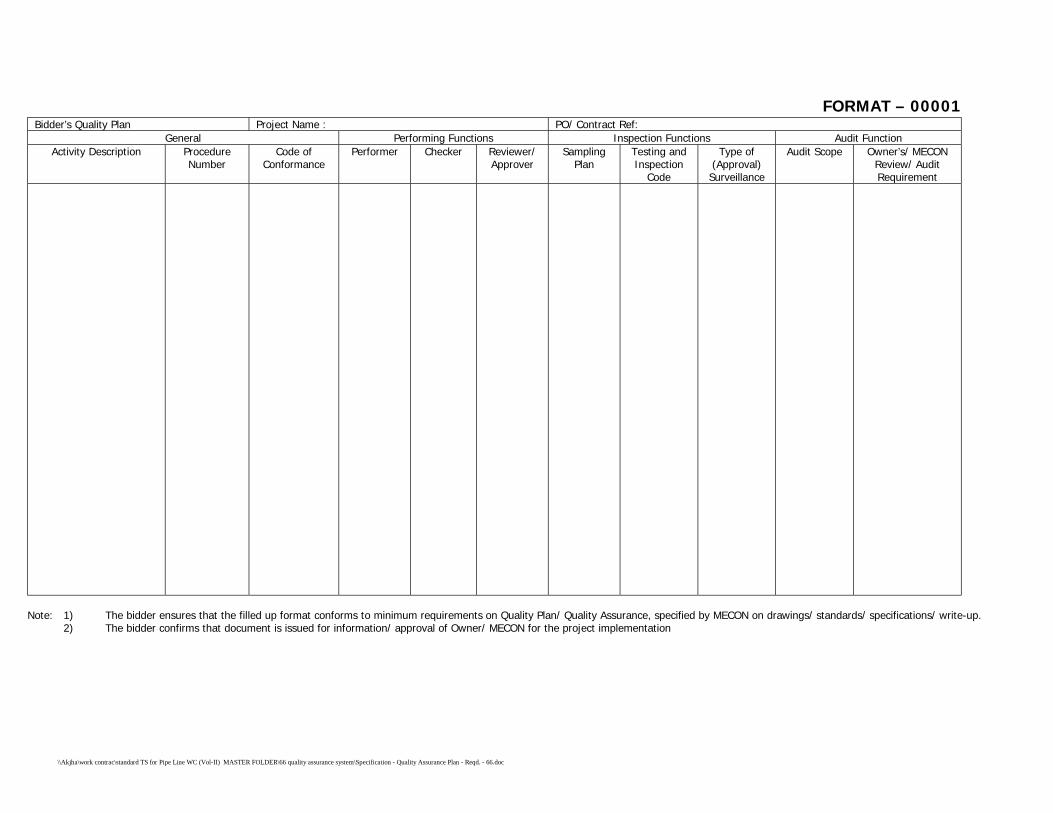
\\Akjha\work contrac\standard TS for Pipe Line WC (Vol-II) MASTER FOLDER\66 quality assurance system\Specification - Quality Assurance Plan - Reqd. - 66.doc
FORMAT – 00001Bidder’s Quality Plan Project Name : PO/ Contract Ref:
General Performing Functions Inspection Functions Audit FunctionActivity Description Procedure
NumberCode of
ConformancePerformer Checker Reviewer/
ApproverSampling
PlanTesting andInspection
Code
Type of(Approval)
Surveillance
Audit Scope Owner’s/ MECONReview/ AuditRequirement
Note: 1) The bidder ensures that the filled up format conforms to minimum requirements on Quality Plan/ Quality Assurance, specified by MECON on drawings/ standards/ specifications/ write-up.2) The bidder confirms that document is issued for information/ approval of Owner/ MECON for the project implementation
\\Akjha\work contrac\standard TS for Pipe Line WC (Vol-II) MASTER FOLDER\70 caliper pigging spec\Specification for Caliper Pigging - 70.doc
SPECIFICATION
FOR
CALIPER PIGGING
SPECIFICATION NO. MEC/S/05/62/70
(PROCESS & PIPELINE DESIGN SECTION)
MECON LIMITEDDELHI - 110 092
\\Akjha\work contrac\standard TS for Pipe Line WC (Vol-II) MASTER FOLDER\70 caliper pigging spec\Specification for Caliper Pigging - 70.doc
C O N T E N T S
Sl. No. Description Page No.
1.0 INTENT 1
2.0 OBJECTIVE 1
3.0 SCOPE OF WORK 1
4.0 VELOCITY OF DIFFERENT PIGS 2
5.0 FOAM PIG RUN 2
6.0 GAUGE PIG RUN 3
7.0 CLEANING PIG RUN 3
8.0 CALIPER PIG RUN 4
9.0 PIG TRACKING 5
10.0 MARKER DEVICES 5
11.0 DEFECT VERIFICATION 6
12.0 ABNORMAL SITUATIONS 6
13.0 WORK REPORT 7
14.0 INFORMATION TO BE FURNISHED BY BIDDER 8
\\Akjha\work contrac\standard TS for Pipe Line WC (Vol-II) MASTER FOLDER\70 caliper pigging spec\Specification for Caliper Pigging - 70.doc Page 1 of 9
SPECIFICATION FOR CALIPER PIGGING
1.0 INTENT
The intent of this specification is to setforth the requirements of the
caliper pigging. The specification is not intended to be all-inclusive and the
use of this specification will not absolve the contractor of his responsibility
of generating valid, interpretable and physically verifiable data.
2.0 OBJECTIVE
The objective of the present pigging programme to access the internal
geometry of the following pipelines and detect significant geometry
defects if any, which may affect safe operation of the pipeline.
The relevant technical specifications of the pipeline including launcher and
receiver details in the Annexure.
3.0 SCOPE OF WORK
To achieve the above objective, contractors SCOPE OF WORK includes
running of adequate numbers of foam pigs, cleaning pigs (magnet, brush,
commination of brush and magnet, scraper, pin wheel etc.), gauge pig
and caliper pig.
Further the scope of work comprises supply of skilled personnel, all
equipment e.g. foam pigs cleaning pigs, gauging pig, caliper pigs, pig
locating and pig tracking devices, spares consumables, communication
and transportation including their mobilisation and demobilisation. It is
expressly understood that this do not limit the scope of work of the
CONTRACTOR in any way. The quantities to be mobilized for different
equipment (different types of pigs pig tracking device, marker device)
accessories, spare and consumables need to be carefully evaluate by the
CONTRACTOR taking in to the consideration that caliper pigging of various
\\Akjha\work contrac\standard TS for Pipe Line WC (Vol-II) MASTER FOLDER\70 caliper pigging spec\Specification for Caliper Pigging - 70.doc Page 2 of 9
pipelines in the scope of work should be carried out without any constraint
and turn around time.
The contractor shall submit the details of each type of pig including foam,
gauge cleaning and caliper for approval of MECON/ GAIL, which he
proposes to use. Pigs shall be launched in the pipeline only after their
design and size has been approved by MECON/ GAIL. Due care shall be
taken not to damage internal coating by the contractor, while proposing
the pigs for internally coated pipeline.
The detailed scope of work shall be, but not limited to under
- Supply of all equipment, personnel and consumables.
- Running of foam, Gauge, Cleaning and Caliper pigs and Tracking to
generate valid data.
- Placement of marker devices along the Row over the pipeline.
- Identification of defects in the field as found
- Preparation of work reports.
4.0 VELOCITY OF DIFFERENT PIGS
Contractor shall be required to maintain velocities of propelling medium in
such a way that the objective of each pig run shall be achieved.
5.0 FOAM PIG RUN
Contractor to carry out adequate number of foam pigs runs in each
pipeline covered under Scope of Work prior to running of cleaning pigs to
make a final assessment of the line piggability to the satisfaction of the
Contractor and provide detailed daily site report for each run in the
approved format before commencing the subsequent run. Contractor to
select size of the foam pigs in such a way that the objective shall be
achieved.
\\Akjha\work contrac\standard TS for Pipe Line WC (Vol-II) MASTER FOLDER\70 caliper pigging spec\Specification for Caliper Pigging - 70.doc Page 3 of 9
6.0 GAUGE PIG RUN
Contractor to carry out adequate number of gauging pig runs in each
pipeline covered under Scope of work including pig tracking for pipeline to
assess any internal restriction in the pipeline that may restrict the passage
of cleaning and caliper pig. Contractor to provide detailed daily site report
for each run in the approved format before commencing the subsequent
run Gauge pig shall be equipped with a gauge plate made of Aluminium
having its diameters 95% of minimum pipeline Internal Diameter (I.D.).
The gauge pig should be able to pass over or negotiate lateral tees or
bends on the pipeline.
7.0 CLEANING PIG RUN
7.1 Pipelines with Internal Coating
Contractor to carry out adequate number of cleaning pig runs by running
suitable cleaning pigs in the pipelines including pig tracking till such time
contractor is satisified with himself about the degree of cleanliness of
pipeline and provide detailed daily site report for each run in the approved
format before commencing the subsequent run. Choice of the type of
cleaning pig has been left to the contractor. The contractor shall assure
that the pigs, which are proposed to be used, are adequately soft and
they do not damage internal coating under any circumstances. The
brushes and scrappers used shall be of nonmetallic/ plastic material.
However, the details of these pigs including their construction details of
brushes, scrappers etc. (if applicable) shall be submitted to MECON/ GAIL
for approval before their usage.
7.2 Pipelines Without Internal Coating
CONTRACTOR to carry out adequate numbers of cleaning pig runs by
running suitable cleaning pigs in pipeline covered under SCOPE OF WORK
including pig tracking till such time CONTRACTOR is satisfied with himself
\\Akjha\work contrac\standard TS for Pipe Line WC (Vol-II) MASTER FOLDER\70 caliper pigging spec\Specification for Caliper Pigging - 70.doc Page 4 of 9
about the degree of cleanliness of pipeline and provide detailed daily site
report for each run in the approved format before commencing the
subsequent run. Choice of the type of cleaning pig has been left to the
contractor. Contractor may deploy brush cleaning pig, magnetic cleaning
pig, combination of brush and magnet, scrapper pig etc. the cleaning pigs
should be able to pass over negotiate lateral tees or bends on the pipeline
8.0 CALIPER PIG RUN
CONTRACTOR to carry out adequate number of electronic geometry
(caliper) pig runs each pipeline covered under SCOPE OF WORK including
pig tracking for each pipeline decided after findings of gauging pig run to
generate valid and interpretable geometry data of the pipeline and
analysis of data of the caliper survey to detect the nature, extent and
location of geometry defect. Contractor to provide detailed daily site
report for each run in the approved format before commencing the
subsequent run. The caliper should be capable of inspecting entire length
of the pipeline i.e. from launcher to receiver in single run. Battery life
should be adequate to commensurate with the run time required to travel
the pipeline length. The electronic recorder system should have requisite
data storage capacity. The drive cups should have requisite resistance to
wear and tear to maintain effective seal throughout the entire run time.
The measurement shall cover the entire 360° of internal pipe wall
circumference using properly oriented and suffcient quantity of sensors.
For internally coated pipelines adequate care shall be taken by using soft
cups so that no damage takes place to the internal coating of pipe. The
tool shall be capable to identify and locate the following features as
minimum.
- Individual Girth weld
- Dent, ovality, buckles, or any other out of roundness, change in
pipeline I.D. and difference of thickness.
- Bend with bend radius and degree of bend.
\\Akjha\work contrac\standard TS for Pipe Line WC (Vol-II) MASTER FOLDER\70 caliper pigging spec\Specification for Caliper Pigging - 70.doc Page 5 of 9
- Valves or any partially closed valves.
- Tees/ off-takes.
The caliper pig should have minimum capability to identify and detect the
defects of following threshold.
Dent : 3% of outer diameter (O. D.)
Ovality : 5% of outer Diameter (O. D.)
Location accuracy : Axial ± 3.0m
Circumferential : ± 12°
(For dents, ovalities and pipeline feature as detailed above).
9.0 PIG TRACKING
The movement of any type of pig (Except, foam pig) put into the line
during caliper pigging shall be required to be monitored along the pipeline
length from launcher to receiver trap. The BIDDER shall detail out the
complete methodology of pig tracking proposed to be deployed by him
including complete technical details of the equipment and device proposed
to be used for this purpose.
It is proposed that pig tracking would be done in a discrete manner at
least 5 to and 10 km - interval on each pipeline at preselected locations.
The exact KM chainage of these locations shall be decided at site in
consultation with the Contractor and CONSULTANT/ COMPANY.
10.0 MARKER DEVICES
The contractor shall submit the details of marker devices, which he
proposes to place for relocating the defect accurately in the field, when
the same has been identified as a result of Caliper survey.
\\Akjha\work contrac\standard TS for Pipe Line WC (Vol-II) MASTER FOLDER\70 caliper pigging spec\Specification for Caliper Pigging - 70.doc Page 6 of 9
The contractor shall be responsible for placing these devices (Marker
Magnets or Locator coils or any other device) at suitable interval so that
the defect can be easily located in the field with minimum above ground
measurement. It may be noted that placement of marker devices, their
retrieval and locating the identified defect in the field shall be the
responsibility of the contractor. The liquidation of defects, if any, is
however, not included in the scope of work of the contract.
11.0 DEFECT VERIFICATION
At the discretion of the COMPANY/ CONSULTANT identify at least two
verification dig sites for each pipeline jointly with MECON and GAIL from
the recorded data and provide MECON/ GAIL with their distance from the
nearest pipeline feature or reference marker to facilitate location of defect
in the field.
The contractor shall depute his representative to observe the verification
at verification sites for proving that filed log detected anomalies conform
to sizing including linear and circumferential positions.
12.0 ABNORMAL SITUATIONS
The objective of this section is to write down foreseeable abnormal
circumstances for taking appropriate measures, should such a condition
arise during implementation of project.
The following abnormal condition have been foreseen by the Comapny.
However, if the BIDDER foresees any other abnormal condition, he is free
to make a mention of the same in his technical BID offer:
12.1 Tool Failure
CONTRACTOR is required to get valid interpretable and verifiable data for
pipeline. In case CONTRACTOR’S equipment fails to perform electronic
\\Akjha\work contrac\standard TS for Pipe Line WC (Vol-II) MASTER FOLDER\70 caliper pigging spec\Specification for Caliper Pigging - 70.doc Page 7 of 9
geometry inspection to generate valid data for any of the pipeline,
CONTRACTOR will make extra runs of pigs to get valid and physically
verifiable data.
12.2 Stuck-Up Tool
The BIDDER shall details out a contingency plan in his BID as proposed by
him in case any of the pigs get stuck up. The plan shall identify procedure
for exactly locating the stuck up pig, detail procedure for retrieval of pig,
equipment, including support facilities required to retrieve the pig.
If pig do not move from stuck up location, by any measure, then the
pipeline section shall have to be cut for retrieval of Pig. Necessary
erection, fabrication and modification of pipe with new pipe piece after
retrieval of pig shall be done by Contractor. The cost for this works shall
be borne by Contractor on actuals. After fabrication & erection, pigging
contractor shall run Gauge pig to check internal restriction, if any.
Locating the stuck up pig and its retrieval shall be the responsibility of the
CONTRACTOR.
13.0 WORK REPORT
The work report shall be prepared and submitted in hard copy (4 sets)
and Electronics media (2 sets)
The work report shall consist of following as a minimum.
- All field activities.
- Equipment description
- List of installations
- List of significance with feature information and installation
reference
- Survey log and enlargement areas of special interest to suitable
scale.
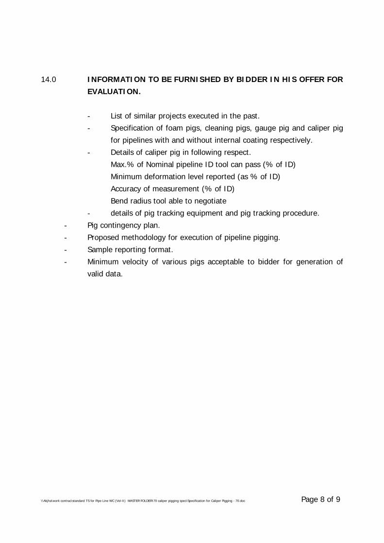
\\Akjha\work contrac\standard TS for Pipe Line WC (Vol-II) MASTER FOLDER\70 caliper pigging spec\Specification for Caliper Pigging - 70.doc Page 8 of 9
14.0 INFORMATION TO BE FURNISHED BY BIDDER IN HIS OFFER FOREVALUATION.
- List of similar projects executed in the past.
- Specification of foam pigs, cleaning pigs, gauge pig and caliper pig
for pipelines with and without internal coating respectively.
- Details of caliper pig in following respect.
Max.% of Nominal pipeline ID tool can pass (% of ID)
Minimum deformation level reported (as % of ID)
Accuracy of measurement (% of ID)
Bend radius tool able to negotiate
- details of pig tracking equipment and pig tracking procedure.
- Pig contingency plan.
- Proposed methodology for execution of pipeline pigging.
- Sample reporting format.
- Minimum velocity of various pigs acceptable to bidder for generation of
valid data.
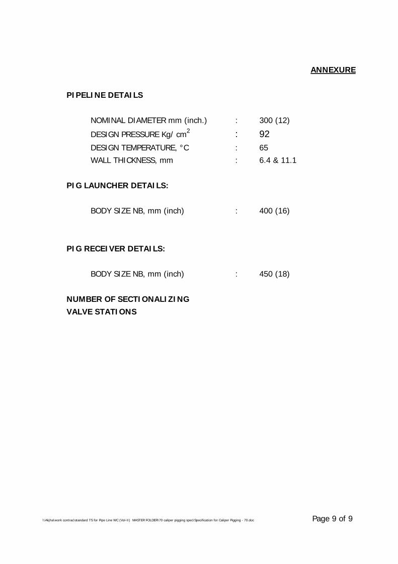
\\Akjha\work contrac\standard TS for Pipe Line WC (Vol-II) MASTER FOLDER\70 caliper pigging spec\Specification for Caliper Pigging - 70.doc Page 9 of 9
ANNEXURE
PIPELINE DETAILS
NOMINAL DIAMETER mm (inch.) : 300 (12)
DESIGN PRESSURE Kg/ cm2 : 92DESIGN TEMPERATURE, °C : 65
WALL THICKNESS, mm : 6.4 & 11.1
PIG LAUNCHER DETAILS:
BODY SIZE NB, mm (inch) : 400 (16)
PIG RECEIVER DETAILS:
BODY SIZE NB, mm (inch) : 450 (18)
NUMBER OF SECTIONALIZINGVALVE STATIONS
SPECIFICATIONSFOR
FIELD JOINT COATINGS OF PIPELINEFOR HDD CROSSING
SPECIFICATION NO. MEC/S/05/62/074
(PROCESS & PIPELINE DESIGN SECTION)MECON LIMITED
DELHI - 110 092
CONTENTS
Sl.No. Description Page No.
1.0 SCOPE 01 -01
2.0 REFERENCE DOCUMENTS 01 -02
3.0 SPECIFICATION FOR FIELD JOINT COATING MATERIAL 02 - 07
4.0 APPLICATION PROCEDURE 08 -11
5.0 INSPECTION 11 - 12
6.0 TESTING 12 - 12
7.0 REPAIR OF FIELD JOINT COATING 13 - 13
8.0 REPAIR OF PIPE COATING DEFECTS 14 - 14
9.0 DOCUMENT 14 - 14
\\Akjha\work contrac\standard TS for Pipe Line WC (Vol-II) MASTER FOLDER\74 field joint for HDD crossing\Specification for FPJ Coating for HDD Crossing - 074-f.doc Page 1 of 14
1.0 SCOPE
1.1 General
This specification covers the minimum requirement for application of anti-corrosion field joints coating on welded pipe section and field tie-in jointsreferred to here in after as Joint(s). The contractor shall perform all work inaccordance with this specification, latest pipeline coating practices and tothe full satisfaction of the Owner. The anti-corrosion pipe joint coating shallbe compatible with yard applied, Ultra Violet (UV) radiation protected, 3layer side extruded polyethylene coating conforming to DIN-30670. Thesleeve width shall be suitable for cut back of 120 ± 20 mm to be left atboth the ends of coated pipes. The job includes supply of all materialsequipment, consumables, labour, supervision, quality control, inspectionrepairs.
1.2 Manpower, Material & Equipment
1.2.1 The Contractor shall supply wrap around heat shrinkable sleeves which iscomposed of two parts such as adhesive coated wrap around and acurable modified epoxy primer alongwith applicator pads.
1.2.2 The supply of wrap around heat shrinkable sleeve shall be underContractor’s scope.
1.2.3 The Contractor shall provide all skilled/ unskilled personnel required forexecution of this work.
1.2.4 The joint coating operation starting from cleaning and surface preparationtill application of joint coating and wrapping of the pipe joints shall beperformed under the supervision of skilled personnel who are well versedin the work.
1.2.5 Contractor shall at his own cost provide a fully equipped laboratory andtest facilities with adequate inventory to carry out tests required forprocedure qualification and during regular production, for testing of jointcoating system.
2.0 REFERENCE DOCUMENTS
2.1 Provision of the following documents/ codes shall generally be followed forstandard of specification and workmanship.
a) DIN – 30672 : Corrosion protection tapes and Heat ShrinkableSleeves.
\\Akjha\work contrac\standard TS for Pipe Line WC (Vol-II) MASTER FOLDER\74 field joint for HDD crossing\Specification for FPJ Coating for HDD Crossing - 074-f.doc Page 2 of 14
b) SIS – 055900 : Pictorial surface preparation standard for paintingsteel surfaces.
c) SSPC – SP1 : Steel structure painting council – Solvent Cleaning.
2.2 In case of conflict between the requirements of this specification and thatof above referred documents/ codes, the requirements of thisspecifications shall govern.
3.0 SPECIFICATION FOR FIELD JOINT COATING MATERIAL
3.1 General
This scope covers the minimum requirement of materials, equipmentrequired for installation of field joint coating by wraparound fibre-reinforcement heat-shrinkable sleeve used for corrosion protection andsealing of field joints in pipelines that are forced through the soil byHorizontal Directional Drilling technique. The sleeves shall be suitable for3LPE/FBE coated pipes operating up to 60°C continuously.
3.1.1 Each Joint Coating System shall consist of :
a) A wraparound heat shrinkable sleeve reinforced with fibre-glass.The sleeve shall be coated with a higher- shear- strengththermoplastic hot-melt adhesive.
b) A solvent-free, two component liquid epoxy primer
c) A specifically designed wear cone
d) A clamping belt
3.1.2 Sleeve Backing
The heat shrinkable sleeves shall be manufactured from minimum 1.0 mmthick radiation cross linked, thermally stabilized, UV -resistant heat-shrinkable fabric, composed of a fibre glass reinforcement and polyolefinfibres, embedded in a polyolefin matrix.
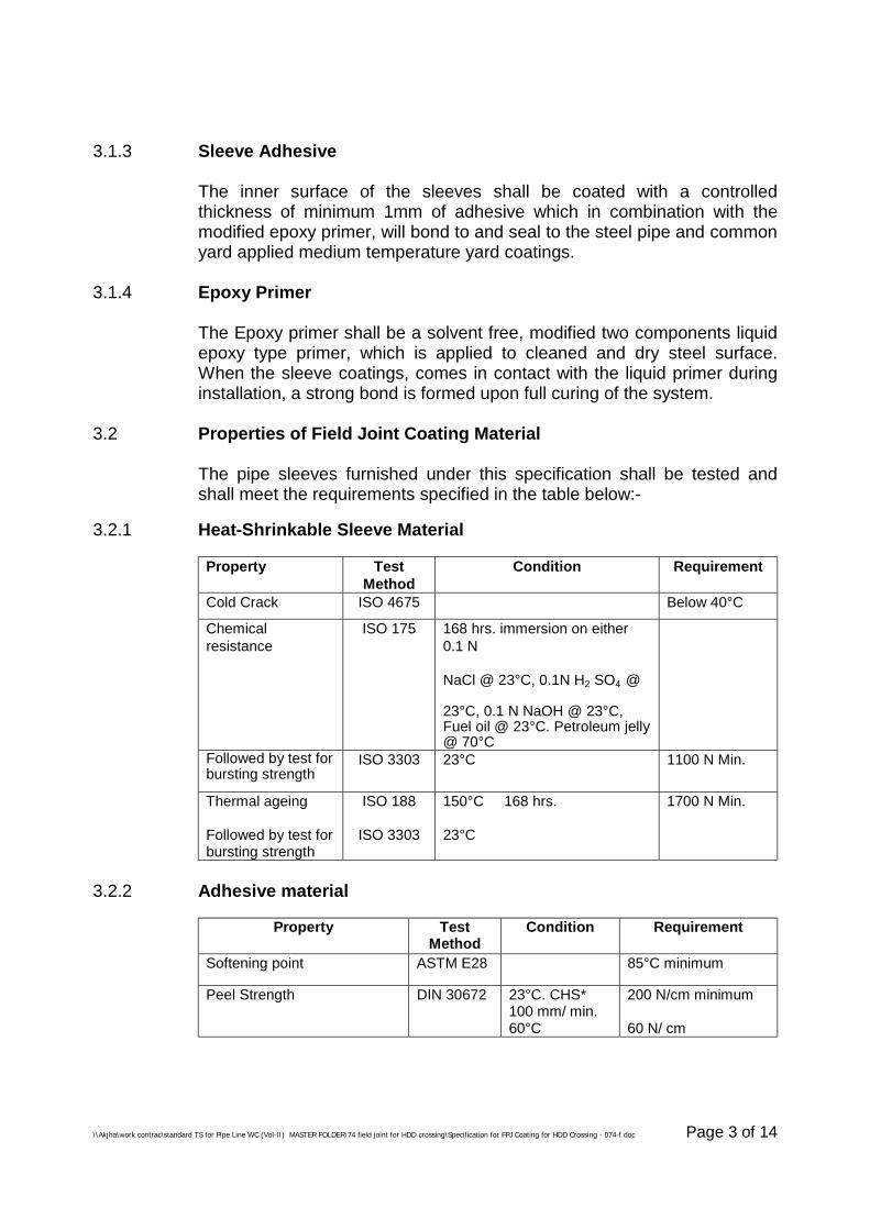
\\Akjha\work contrac\standard TS for Pipe Line WC (Vol-II) MASTER FOLDER\74 field joint for HDD crossing\Specification for FPJ Coating for HDD Crossing - 074-f.doc Page 3 of 14
3.1.3 Sleeve Adhesive
The inner surface of the sleeves shall be coated with a controlledthickness of minimum 1mm of adhesive which in combination with themodified epoxy primer, will bond to and seal to the steel pipe and commonyard applied medium temperature yard coatings.
3.1.4 Epoxy Primer
The Epoxy primer shall be a solvent free, modified two components liquidepoxy type primer, which is applied to cleaned and dry steel surface.When the sleeve coatings, comes in contact with the liquid primer duringinstallation, a strong bond is formed upon full curing of the system.
3.2 Properties of Field Joint Coating Material
The pipe sleeves furnished under this specification shall be tested andshall meet the requirements specified in the table below:-
3.2.1 Heat-Shrinkable Sleeve Material
Property TestMethod
Condition Requirement
Cold Crack ISO 4675 Below 40°C
Chemicalresistance
ISO 175 168 hrs. immersion on either0.1 N
NaCl @ 23°C, 0.1N H2 SO4 @
23°C, 0.1 N NaOH @ 23°C,Fuel oil @ 23°C. Petroleum jelly@ 70°C
Followed by test forbursting strength
ISO 3303 23°C 1100 N Min.
Thermal ageing
Followed by test forbursting strength
ISO 188
ISO 3303
150°C 168 hrs.
23°C
1700 N Min.
3.2.2 Adhesive material
Property TestMethod
Condition Requirement
Softening point ASTM E28 85°C minimum
Peel Strength DIN 30672 23°C. CHS*100 mm/ min.60°C
200 N/cm minimum
60 N/ cm
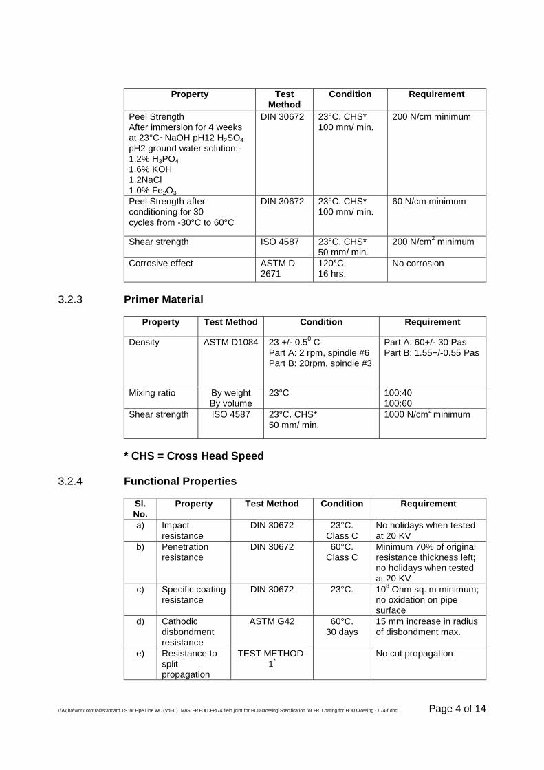
\\Akjha\work contrac\standard TS for Pipe Line WC (Vol-II) MASTER FOLDER\74 field joint for HDD crossing\Specification for FPJ Coating for HDD Crossing - 074-f.doc Page 4 of 14
Property TestMethod
Condition Requirement
Peel StrengthAfter immersion for 4 weeksat 23°C~NaOH pH12 H2SO4pH2 ground water solution:-1.2% H3PO41.6% KOH1.2NaCl1.0% Fe2O3
DIN 30672 23°C. CHS*100 mm/ min.
200 N/cm minimum
Peel Strength afterconditioning for 30cycles from -30°C to 60°C
DIN 30672 23°C. CHS*100 mm/ min.
60 N/cm minimum
Shear strength ISO 4587 23°C. CHS*50 mm/ min.
200 N/cm2 minimum
Corrosive effect ASTM D2671
120°C.16 hrs.
No corrosion
3.2.3 Primer Material
Property Test Method Condition Requirement
Density ASTM D1084 23 +/- 0.50 CPart A: 2 rpm, spindle #6Part B: 20rpm, spindle #3
Part A: 60+/- 30 PasPart B: 1.55+/-0.55 Pas
Mixing ratio By weightBy volume
23°C 100:40100:60
Shear strength ISO 4587 23°C. CHS*50 mm/ min.
1000 N/cm2 minimum
* CHS = Cross Head Speed
3.2.4 Functional Properties
Sl.No.
Property Test Method Condition Requirement
a) Impactresistance
DIN 30672 23°C.Class C
No holidays when testedat 20 KV
b) Penetrationresistance
DIN 30672 60°C.Class C
Minimum 70% of originalresistance thickness left;no holidays when testedat 20 KV
c) Specific coatingresistance
DIN 30672 23°C. 108 Ohm sq. m minimum;no oxidation on pipesurface
d) Cathodicdisbondmentresistance
ASTM G42 60°C.30 days
15 mm increase in radiusof disbondment max.
e) Resistance tosplitpropagation
TEST METHOD-1*
No cut propagation
\\Akjha\work contrac\standard TS for Pipe Line WC (Vol-II) MASTER FOLDER\74 field joint for HDD crossing\Specification for FPJ Coating for HDD Crossing - 074-f.doc Page 5 of 14
Sl.No.
Property Test Method Condition Requirement
f) Resistance tocircumferentialedge loading
TEST METHOD-2*
50 KN minimum
g) Resistance tolocal edgeloading (chiseltest)
TEST METHOD-3*
6 KN minimum
*Test Methods
3.3 Test Methods
3.3.1 Resistance to split propagation (Test Method -1)
A rectangular piece of 50mm width by 150 mm length shall be cut from thematerial as delivered. A 5mm long, clean cut shall be made mid-way in thepiece along once of the long edges perpendicular to this edge. Thesample shall be mounted on a clamp that holds it securely and avoids anyshrinking during testing.
The assembly shall be placed in an air-circulating oven present at 1700C.
After 15 minutes, the sample shall be removed from the oven, allowed tocool down to room temperature and examined for cut propagation.
This test simulates the unlikely event when the sleeve gets cut during theinstallation phase. Sleeves based upon extruded polyelfin show a distincttendency to propagate the cut along the total width of the sleeve. Sleevessuitable for HDD works shall not exhibit this behaviour.
3.3.2 Resistance to circumferential edge loading (Test method -2)
The sleeve shall be installed on a DN 200 three -layer PE coated steelpipe piece. A thick wall steel ring that fits a DN 200 three-layer PE coatedsteel pipe with a tolerance of 0.2+-0.2 mm shall be positioned against thefront edge of the wear cone sleeve and then pushed towards the sleevesystem at a constant speed of 5 mm/ min over a distance of 50 mm. Theforces necessary shall continuously be registered. The minimum requiredforce shall be less than 50 KN.
During the pushing or pulling operation, any obstacle protruding from thesmooth pipe surface is loaded by the surrounding soil that passes by. Thistest simulates the shear forces that are exerted on to the sleeve by rigidsoil type.
3.3.3 Resistance to local edge loading (Chisel test: Test Method -3)
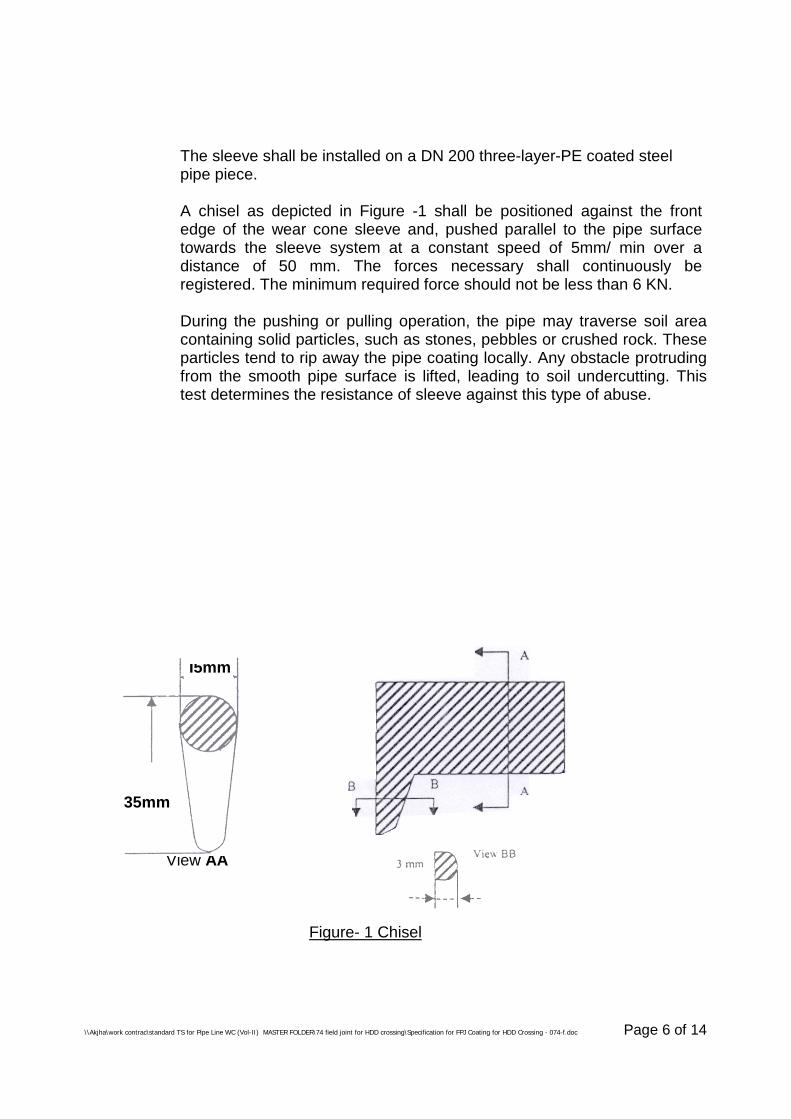
\\Akjha\work contrac\standard TS for Pipe Line WC (Vol-II) MASTER FOLDER\74 field joint for HDD crossing\Specification for FPJ Coating for HDD Crossing - 074-f.doc Page 6 of 14
The sleeve shall be installed on a DN 200 three-layer-PE coated steelpipe piece.
A chisel as depicted in Figure -1 shall be positioned against the frontedge of the wear cone sleeve and, pushed parallel to the pipe surfacetowards the sleeve system at a constant speed of 5mm/ min over adistance of 50 mm. The forces necessary shall continuously beregistered. The minimum required force should not be less than 6 KN.
During the pushing or pulling operation, the pipe may traverse soil areacontaining solid particles, such as stones, pebbles or crushed rock. Theseparticles tend to rip away the pipe coating locally. Any obstacle protrudingfrom the smooth pipe surface is lifted, leading to soil undercutting. Thistest determines the resistance of sleeve against this type of abuse.
I5mm
35mm
View AA
Figure- 1 Chisel
\\Akjha\work contrac\standard TS for Pipe Line WC (Vol-II) MASTER FOLDER\74 field joint for HDD crossing\Specification for FPJ Coating for HDD Crossing - 074-f.doc Page 7 of 14
3.4 Qualification for Contractor’s supplied Materials and theirManufacturer
3.4.1 Prior to procurement of coating materials, Contractor shall furnish thefollowing information for qualification of the Manufacturer and material:
a. Complete descriptive technical catalogs describing the materialsoffered along with samples of corrosion coating materials, itsproperties and application instruction as applicable specifically tothe project.
b. Reference list of previous supplies, in last 5 years, of the similarmaterial or manufacturer shall be notified to Company, whoseapproval in writing of all charges shall be obtained before thematerials are manufactured.
3.4.2 Contractor shall ensure that the coating materials supplied by him areproperly packed and clearly marked with the following :-
- Manufacturer’s name
- Material Qualification Certificate Number
- Batch Number
- Date of Manufacturing and date of expiry
3.4.3 Prior to shipment of materials from the Manufacturer’s Works. Contractorshall furnish the following documents:
a. Test certificate/results as per Manufacturer’s Quality ControlProcedure for each batch of materials complying with therequirements of relevant sub-clauses of clause no. 3.2 of the thisspecification.
b. Specific application instructions with pictorial illustrations.c. Specific storage and handling instructions.
3.4.4 All documents shall be in English language only.
3.5 Storage of Materials
Material shall be stored in sheltered storage by the Contractor in themanufacturer’s original packing and away from direct sunlight and inaccordance with manufacturer’s instructions.
4.0 APPLICATION PROCEDURE
\\Akjha\work contrac\standard TS for Pipe Line WC (Vol-II) MASTER FOLDER\74 field joint for HDD crossing\Specification for FPJ Coating for HDD Crossing - 074-f.doc Page 8 of 14
4.1 General
a) The application procedure shall be in accordance withmanufacturer’s instruction and the minimum requirements requiredbelow whichever are the most stringent and shall be demonstratedto and approved by the Owner.
b) Contractor shall provide and maintain mobile facilities whichcontains all necessary tools, propane torches, epoxy primer pumps,silicon rollers, testing instruments, equipment, and spares forcleaning, coating, repairs, inspection and testing.
c) Contractor shall furnish sufficient number of the followingequipment and the required spares as a minimum for inspectionand testing purpose for each crew :
- Fully automatic full circle adjustable holiday detector withaudio and visual output signal for inspection of coating.
- Portable Tensile Strength Tester- Digital Thermometer- Solid state digital thickness gauge for measuring thickness
of joint coating.
4.2 Pipe Surface Preparation
a) The Contractor shall thoroughly clean and dry the joint surface bypower tool cleaning in accordance with SSPC-SP1. The completeprocedure and details of equipment used shall be prepared by theContractor for Owner’s approval prior to commencement of jointcoating work.
b) Prior to cleaning operation, Contractor shall visually examine thejoint surface area and shall ensure that all defects, flats and otherdamages have been repaired or removed.
c) Where oil, grease or other materials detrimental to the finishedcoating is present, it shall be removed with a continuous removalsolvents cleaning system to remove completely all such materials inaccordance with SSPC-SP1.
d) The standard of finish for cleaned pipe surface shall conform to SA2½ of Swedish Standard SIS-055900 latest edition. The degree ofpreparation required to obtain an end product that fulfil the
\\Akjha\work contrac\standard TS for Pipe Line WC (Vol-II) MASTER FOLDER\74 field joint for HDD crossing\Specification for FPJ Coating for HDD Crossing - 074-f.doc Page 9 of 14
requirements of this specification may not be sufficiently coveredand is not limited by SIS-055900. Surface of pipe after shot blastingshall be have an anchor pattern of 50 to 70 microns. This shall bemeasured by a suitable instrument such as Elecometer.
e) Piper temperature immediately prior to blasting shall be minimum20°C. At no time shall be blast cleaning be performed when therelative humidity exceeds 85%. Surface temperature must be atleast 3°C above the dew point temperature.
f) The abrasive blast material shall be free of impurities andinclusions, water and oil. All abrasives shall be removed after blastby brush or vacuum type cleaner prior to applying joint coating.The abrasive shall be stored in a dry condition and maintained dryduring use.
g) The compressed air for blasting shall be free of water and oil.Contractor to verify air cleanliness at the start of the work and everyfour hours thereafter. Separators and the traps shall be provided atthe compressor and blasting station. Separators and traps shall bechecked daily for effective moisture and oil removal during coatingoperations.
h) The ends of existing line pipe protective coating shall be inspectedand chamfered. Unbonded portions of the coating shall beremoved and then suitably trimmed. Portions where parent coatingis removed shall be thoroughly cleaned as specified.
i) Pipe shall be visually inspected by Contractor immediately afterblast cleaning for surface defects such as slivers, laminations,leafing, scores, indentation slugs or any other defects consideredinjurious to the coating integrity. Such defects shall be reported toOwner and on permission from Owner, such defects shall beremoved by filling or grinding in such a way as not to “blue” thesteel.
\\Akjha\work contrac\standard TS for Pipe Line WC (Vol-II) MASTER FOLDER\74 field joint for HDD crossing\Specification for FPJ Coating for HDD Crossing - 074-f.doc Page 10 of 14
4.3 Procedure
a) The application procedure shall be in accordance withmanufacturers instruction and the minimum requirements specifiedbelow whichever are the most stringent and shall be demonstratedto and approved by the owner.
b) Applicators for coating application shall be given necessaryinstructions and training before start of work by theCONTRACTOR. To verify and qualify the application procedures,all coating applied during the qualification test, shall be removed fordestructive testing until the requirements stated in sections‘Inspection’ and ‘testing’ of this specification are met.
c) Prior to surface cleaning, the surface shall be completely dry. Aneffective heating equipment which shall not give rise to depositsshall be used. Care shall be taken to avoid damage to existingcoating.
d) All pipe joint surfaces shall be thoroughly examined before theapplication of the coating in order to ensure that the surfaces arefree of oil, grease, rust, mud, earth or any other foreign matter.
e) Liquid epoxy primer shall be applied on the joints immediately afterthe completion of heating operation.
f) The heat shrink sleeve is then wraparound the joint while the primeris still wet and shall overlap the existing pipe coating by minimum100 mm on each side.
g) The wraparound sleeve is shrunk on pipe joint with a propane torchmoved back and forth over the surface when heated above 125°C,the sleeve shall shrink tightly around the substrate on to the wet-primer. At the time of application of the primer, th pipe surfacetemperature shall be at least 60°C at every point. To check this,approved temperature indicators shall be used . temperatureindicating crayons shall not be used.
h) The wraparound sleeve shall be entirely wrapped around the pipepositioning the closure patch off to one side of the pipe in 10m or 2O’clock position, with edge of the undergoing layer facing upwardand an overlap of min. 100 mm.
i) Heat shrinking shall be procedure shall be applied to shrink thesleeve in such a manner that all entrapped air is removed usinggloved hands and hand rollers. The complete shrinking of entire
\\Akjha\work contrac\standard TS for Pipe Line WC (Vol-II) MASTER FOLDER\74 field joint for HDD crossing\Specification for FPJ Coating for HDD Crossing - 074-f.doc Page 11 of 14
sleeves shall be obtained without undue heating of existing pipecoating and providing due bonding between pipe, sleeve and pipecoating. A thermochrome paint shall be applied a an closure patchto indicate that sufficient heat/ temperature has been obtained. Thejoint coating shall have wear cone applied over the leading edge ofthe sleeve and the clamping belt tightened over it.
j) Application of Wear Cone - The leading edge will be given an extrawear cone. Start by heating the leading edge area of the mainsleeve to 700C. Wrap the leading edge sleeve over the transitionMill coating. Ensure that the closure is placed away from the mainsleeve closure Shrink the leading edge sleeve.
k) Application of Metal Belt - The metal belt shall be applied over thewear cone sleeve. The metal belt will be tightened using thestrapper tool supplied by the manufacturer.
l) Sufficient manpower working on opposite sides of each pipe jointare required for installation of the sleeve.
m) The installed sleeve shall not be disturbed until the adhesive hassolidified.
5.0 INSPECTION
5.1 For wraparound coating, a visual inspection shall be carried out for thefollowing :
- Mastic extrusion on either ends of the sleeves shall be examined- There shall be no sign of punctures or pinholes or bond failure.
The external appearance of the sleeves shall be smooth, free ofdimples, air entrapment or void formation.
- Weld bead profile shall be visible over the sleeves.- The entire closure patch shall have changed colour uniformly.
5.2 Holiday Inspection
5.2.1 The Holiday Detector used shall be checked and calibrated daily with anaccurate D.C. voltmeter. The detector electrode shall be in direct contactwith the surface of coating to be inspected.
5.2.2 The entire surface of the joint section shall be inspected by means of a fullcircle Holiday Detector approved by OWNER set to DC Voltage of at least25 kV for wraparound sleeves. Inspection of the heat shrink sleeve coatingshall be conducted only after the joint has cooled below + 50°C.
\\Akjha\work contrac\standard TS for Pipe Line WC (Vol-II) MASTER FOLDER\74 field joint for HDD crossing\Specification for FPJ Coating for HDD Crossing - 074-f.doc Page 12 of 14
5.2.3 All the coated joints shall be subjected to Holiday Detection test.
5.2.4 An installed sleeve with more than two holiday shall be stripped and a newone be installed.
6.0 TESTING
a) OWNER reserves the right to test one out of every 30 joint coatingsubject to a minimum of 2 joints. CONTRACTOR shall provide allassistance in removing and testing of field joint coatings. Fromeach test sleeve, one or more strips of size 25 mm x 200 mm shallbe cut one perpendicular to the pipe axis and slowly peeled off.This test shall be conducted between either sleeve and metal orsleeve and mill coating as per direction of Owner/ Engineer-in-charge.
b) The required peel strength shall be 60 N/cm (min.) at 23°C. Thesystem shall fail only in the adhesive layer. No failure either inadhesion to steel or adhesion to backing shall be permitted. Theadhesive layer that remains on the pipe surface shall be free ofvoids resulting from air or gas inclusion.
c) If the sleeve taken away for test does not meet the requirement ofclause 6.0 (b), the adjacent two sleeves do not meet therequirements of clause 6.0 (b) the field joint coating shall bestopped until OWNER is satisfied with application methods.
d) For the test tensile strength, two parallel incisions spaced 1 CM.Apart are made right down to the surface of the steel. A furtherincision shall then be at right angles to the first angles to the firsttwo incisions. With the aid of a 1 cm. Wide knife the coating is liftedover a length of about 2 cm. And clamped into the tensile tester,where upon a uniform pull is exerted at an angle of 90 degree. Thetensile strength shall be more than a 2500psi.
e) Coating thickness shall be checked by non destructive method foreach field joint.
\\Akjha\work contrac\standard TS for Pipe Line WC (Vol-II) MASTER FOLDER\74 field joint for HDD crossing\Specification for FPJ Coating for HDD Crossing - 074-f.doc Page 13 of 14
7.0 REPAIR OF FIELD JOINT COATING
7.1 If a field joint is detected to be unacceptable after inspection and testingas per clause no. 6.0 of this specification. The CONTRACTOR shall , athis own cost :
- determine the cause of the faulty results of the coatings.
- mobilise the services of expert of manufactures, if required.
- test to the complete satisfaction of the OWNER, already completedfield joint coatings.
- stop joint coating until remedial measures are taken against thecauses of such failures, to the complete satisfaction of theOWNER.
7.2 CONTRACTOR shall replace all the joints coating found or expected to beunacceptable as per clause no. 6.0 of this specification.
7.3 CONTRACTOR shall, at his own cost repair all areas where the coatinghas been removed for testing by the OWNER or by the CONTRACTORto the complete satisfaction of the OWNER.
7.4 The upright edges of the damaged areas shall be chamfered, in additionto the steel shall be free from rust, dirt, oil and grease. The coating aroundthe damaged area shall be roughened. After thorough mixing (inaccordance with the recommendations of the manufacturer) the filler shallbe applied, to sufficient Thickness with the aid of stooping knife, whilstobserving ample overlap hardening. The material will require the approvalof OWNER.
7.5 After the coating work on welded joints and repairs to the coating havebeen completed, The coating area as a whole shall be tested with spark-tester before pull back/ lowering/jacking the pipeline.
7.6 Company shall be entitled to check the coating on buried pipelines orparts of pipelines with equipment such as the “Pearson meter” and theresistance meter. If the coating defects are established, the Contractorshall be responsible for excavation at such points, repairing the coating,spark testing and backfilling the excavations without extra charge.
\\Akjha\work contrac\standard TS for Pipe Line WC (Vol-II) MASTER FOLDER\74 field joint for HDD crossing\Specification for FPJ Coating for HDD Crossing - 074-f.doc Page 14 of 14
8.0 REPAIR OF PIPE COATING DEFECTS
8.1 Any defect or damage in pipe coating observed till incorporation onpermanent works shall be rectified by the Contractor at his risk and cost.However, for repair of damaged coating observed during taking over ofOwner supplied pipe, if any, shall be paid extra in accordance with therelevant items of Schedule of Rates.
8.2 Field repair of coated pipes shall be carried out by using same type ofwraparound sleeves used for joint coating.
8.3 The repair procedure shall be same as specified herein above forapplication of anti-corrosion field joint coating on welded pipe.
9.0 DOCUMENTATION
9.1 Prior to start the coating works at site Contractor shall furnish followingOwner/ Consultant’s approved documents in addition to that mentioned inclause no. 3.4 of this specification.
- Procedure for field joint coating & their repair- Procedure for repair of pipe line coating defects- Procedure qualification record- Inspection test plan- Inspection format
9.2 Final submission of all documents after finish the work shall be as perrelevant specification & SCC enclosed with the tender or as per directionof Engineer-in-charge.
\\Akjha\work contrac\standard TS for Pipe Line WC (Vol-II) MASTER FOLDER\75 pipe line crossing using HDD method\Specification for PL CUHDDM 75.doc
SPECIFICATIONFOR
PIPELINE CROSSINGSUSING HORIZONTAL DIRECTIONAL
DRILLING METHOD
SPECIFICATION NO. : MEC/S/05/62/75
MECON LIMITEDDELHI - 110 092
MECON LIMITEDDelhi
PROCESS & PIPINGDESIGN SECTION
TECHNICAL SPECIFICATIONFOR
PIPELINE CROSSINGS USINGHORIZONTAL DIRECTIONAL
DRILLING METHOD
TECHNICAL SPECIFICATION NO. : MEC/S/05/62/75 REV-0 Page 1 of 11
\\Akjha\work contrac\standard TS for Pipe Line WC (Vol-II) MASTER FOLDER\75 pipe line crossing using HDD method\Specification for PL CUHDDM 75.doc
C O N T E N T S
Sl.No. Description Page No.
1.0 SCOPE 2
2.0 DESIGN AND ENGINEERING 3 – 6
3.0 CONSTRUCTION 6 – 10
4.0 DOCUMENTATION 10 – 11
PREPARED BY : CHECKED BY : APPROVED BY :
MECON LIMITEDDelhi
PROCESS & PIPINGDESIGN SECTION
TECHNICAL SPECIFICATIONFOR
PIPELINE CROSSINGS USINGHORIZONTAL DIRECTIONAL
DRILLING METHOD
TECHNICAL SPECIFICATION NO. : MEC/S/05/62/75 REV-0 Page 2 of 11
\\Akjha\work contrac\standard TS for Pipe Line WC (Vol-II) MASTER FOLDER\75 pipe line crossing using HDD method\Specification for PL CUHDDM 75.doc
1.0 SCOPE
1.1 This specification covers the minimum requirements for various activities to becarried out by the Contractor for the engineering and construction of pipelinecrossing using directional drilling method.
1.2 This specification shall be read in conjunction with the requirements ofspecification and other documents included in the CONTRACT between ownerand Contractor.
1.3 Contractor shall, execute the work in compliance with laws, by laws, ordinanceand regulations. Contractor shall provide all services, labour, inclusive ofsupervision thereof, supply of all materials (excluding “Owner suppliedMaterial), equipment , appliances etc..
1.4 Contractor shall take full responsibility for the stability and safety of alloperation and methods involved in the work.
1.5 Contractor shall be deemed to have inspected and examined the work areaand its surroundings and to have satisfied himself as far as practicable with thesurface conditions, hydrological and climatic conditions, the extent and natureof the work and materials necessary for the completion of the work, and themeans of access to the work area.
1.6 Contractor shall be deemed to have obtained all necessary information withregard to risks, contingencies and all other circumstances, which may influencethe work.
1.7 Contractor shall, in connection with the work, provide and maintain at his owncosts all lights, guards, fencing, as necessary or directed by Owner or theirrepresentative.
1.8 For the purpose of this specification, the following definitions shall hold.
- The words `Shall’ and `Must’ are mandatory.
- The words `Should, May and Will’ are non mandatory, advisory, orrecommendatory.
1.9 Contractor shall provide free of charge reasonable facilities to Owner’spersonnel to witness all stages of construction.
MECON LIMITEDDelhi
PROCESS & PIPINGDESIGN SECTION
TECHNICAL SPECIFICATIONFOR
PIPELINE CROSSINGS USINGHORIZONTAL DIRECTIONAL
DRILLING METHOD
TECHNICAL SPECIFICATION NO. : MEC/S/05/62/75 REV-0 Page 3 of 11
\\Akjha\work contrac\standard TS for Pipe Line WC (Vol-II) MASTER FOLDER\75 pipe line crossing using HDD method\Specification for PL CUHDDM 75.doc
2.0 DESIGN AND ENGINEERING
2.1 The limits of each crossing shall be determined by the Contractor on the basisof crossing profile based on survey drawings, design, equipment, installationtechnique and site condition. Contractor shall furnish all engineering designcalculation and crossing drawings etc. to owner for their approval prior toexecution of the work.
2.2 Within the entire limits of crossing, the minimum cover to top of coated pipeshall be as specified in the Special Conditions of Contract (SCC).
However, wherever the drilled length for a crossing includes the crossings ofobstacles such as roads, railroads, cannals, streams, etc. The followingminimum requirements of cover to the pipe shall be satisfied unless specifiedotherwise in the scope of work in SCC.
For Road Crossing : 1.4 m from top of road to top of pipe.
For railroad crossing : 1.7 m from base of Rail to top of pipe.
For canal crossing : 1.5 m from lowest bed level to top of pipe.
In case the pipeline crosses other utilities, viz., other pipelines, sewers, drainpipes, water mains, telephone conduits and other underground structures, thepipeline shall be installed with at least 500 mm free clearance from theobstacle or as specified in the drawing or such greater minimum distance asmay be required by authorities having jurisdiction. Also in all cases, theminimum covers specified above shall be maintained within the entire limits ofcrossing.
2.3 The entry and exit points of the pipeline at ground level shall not come withinthe limits of crossing as defined in the crossing drawings.
2.4 Contractor shall carry out calculations for determining the maximumpermissible overburden on pipe, to check that the empty pipeline is safe fromcollapse at any point along the drilled crossing section. Contractor shall submitthese calculations to Owner for approval.
MECON LIMITEDDelhi
PROCESS & PIPINGDESIGN SECTION
TECHNICAL SPECIFICATIONFOR
PIPELINE CROSSINGS USINGHORIZONTAL DIRECTIONAL
DRILLING METHOD
TECHNICAL SPECIFICATION NO. : MEC/S/05/62/75 REV-0 Page 4 of 11
\\Akjha\work contrac\standard TS for Pipe Line WC (Vol-II) MASTER FOLDER\75 pipe line crossing using HDD method\Specification for PL CUHDDM 75.doc
2.5 Pipeline Axis
The plane containing the pipeline route axis shall be perpendicular to thehorizontal plane. There shall be no bending of the pipeline route axis atdepths shall lower than 2 meters below ground level.
2.6 Back-reamed hole and Pipeline Interface
2.6.1 Contractor shall derive combination of:
- Back-reamed hole diameter- Bentonite density- Pipeline submerged weight in bentonite (and means to achieve that
weight)
to optimise the crossing design in terms of pipeline stresses and powerrequirement
2.6.2 Contractor shall indicated what maximum shear stress in the pipeline coatingwill result from his choice of above parameters and other characteristicsdescribed in this section.
2.6.3 Contractor shall furnish all calculations for Onner’s approval. If shear stress inpipe coating is, in the opinion of Owner, beyond the permissible limits,Contractor shall revise his choice of parameters to reduce shear stress on pipecoating to permissible value.
2.7 Contractor shall determine in the minimum allowable elastic bend radius forpipe from the following consideration:
2.7.1 Maximum Longitudinal Stress During Installation
Total maximum longitudinal stress in the pipeline due to tension and bendingat any location shall not exceed 90% of the SMYS of the pipe material.
Contractor shall, in order to check this requirement, evaluate the maximumtensile forces to which the pipeline is subjected to at any phase of itsinstallation during the pulling operation.
MECON LIMITEDDelhi
PROCESS & PIPINGDESIGN SECTION
TECHNICAL SPECIFICATIONFOR
PIPELINE CROSSINGS USINGHORIZONTAL DIRECTIONAL
DRILLING METHOD
TECHNICAL SPECIFICATION NO. : MEC/S/05/62/75 REV-0 Page 5 of 11
\\Akjha\work contrac\standard TS for Pipe Line WC (Vol-II) MASTER FOLDER\75 pipe line crossing using HDD method\Specification for PL CUHDDM 75.doc
2.7.2. Maximum Equivalent Stress During Final Hydrostatic Test
After installation, the pipeline shall be hydrostatically tested to a minimum testpressure equal to 1.4 times the design pressure or at a pressure stipulated inthe Special Conditions of Contract whichever is higher. However, duringhydrostatic testing, the combined equivalent stress in the pipeline due tobending and test pressure shall not exceed 90% of the SMYS of pipe material.
2.7.3 Maximum Equivalent Stress During Service
Permissible values of maximum equivalent stress during services shall begoverned by the requirements of ANSI B 31.8/B 31.4 as applicable. The detailsof pipeline operating parameters are provided in the Special Conditions ofContract.
2.7.4 The minimum allowable radius of curvature for the pipeline shall be thehighest value of the minimum pipeline elastic radius as computed from theconsiderations outlined in clause 2.7.1 to 2.7.3 above after correction fordrilling inaccuracies or multiplication by the factor 1.85. whichever results inthe highest permissible value of minimum elastic bend radius.
2.7.5 Contractor shall submit all calculations for Company’s approval alongwithprocedure.
2.8 Pipeline Configuration along the Support String Before Entry Point
2.8.3 Contractor shall determine the required pipeline configuration in order to allowsmooth pull in the crossing entry point and admissible stress in the supportedpipeline string. Pipeline combined stress shall not exceed 95% of the specifiedminimum yield strength for line pipe material.
2.8.4 Contractor shall furnish all calculation and specify the number of requiredsupports, description of the supports, their co-ordinates and capacity in metrictons.
2.8.5 Contractor shall also furnish a drawing of the launching ramp indicating thepipeline configuration.
2.8.6 The distance between each roller shall also be specified and justified.
MECON LIMITEDDelhi
PROCESS & PIPINGDESIGN SECTION
TECHNICAL SPECIFICATIONFOR
PIPELINE CROSSINGS USINGHORIZONTAL DIRECTIONAL
DRILLING METHOD
TECHNICAL SPECIFICATION NO. : MEC/S/05/62/75 REV-0 Page 6 of 11
\\Akjha\work contrac\standard TS for Pipe Line WC (Vol-II) MASTER FOLDER\75 pipe line crossing using HDD method\Specification for PL CUHDDM 75.doc
2.9 Contractor shall, based on result of design and engineering carried out by him,prepare construction drawings for the crossing and shall submit the same forOwner’s approval. Construction drawings shall indicate the pipeline profile withlevels furnished at sufficient intervals for proper control during construction.Other relevant details viz., entry and exit angles, radius of bends, etc. shallalso be indicated. Contractor shall also calculated the total length of pipelinerequired as well as the maximum tension required on the pull head of the rig.
2.10 All construction works shall be carried out in accordance with the constructiondrawings approved by Owner.
2.11 Before commencement of any field work, Contractor shall furnish for Owner’sapproval all design calculations and construction drawings as stipulated in theabove clauses.
3.0 CONSTRUCTION
Contractor shall comply with all the conditions and requirements issued byAuthorities having jurisdiction in the area where the work is to be performed.
If no public road exists, Contractor shall arrange on his own for access to hiswork area at no extra cost to owner.
3.1.0 Installation Procedure
3.1.1 Contractor shall, before commencing any work at site, submit for Owner’sapproval a detailed installation procedure.
3.1.2 The installation procedure as a minimum shall include the following:
a) Project Organisation Chart:This shall indicate Contractor’s organisational set-up at site andmanpower deployment.
b) Details of fabrication yard and launching areas.
c) Details of Equipment :Contractor shall furnish the complete list of all equipment to bedeployed for preparation of pipe string and installation of crossing.Technical characteristics and capacity of each equipment includinginstrumentation, monitoring and control equipment shall be furnished indetails.
MECON LIMITEDDelhi
PROCESS & PIPINGDESIGN SECTION
TECHNICAL SPECIFICATIONFOR
PIPELINE CROSSINGS USINGHORIZONTAL DIRECTIONAL
DRILLING METHOD
TECHNICAL SPECIFICATION NO. : MEC/S/05/62/75 REV-0 Page 7 of 11
\\Akjha\work contrac\standard TS for Pipe Line WC (Vol-II) MASTER FOLDER\75 pipe line crossing using HDD method\Specification for PL CUHDDM 75.doc
d) Pipeline string preparation details (hauling, stringing, welding etc.)
e) Hydrostatic test procedure (pre and post installation)
f) Disposal methodology of bentonite slurry.
g) Method of installation covering all steps of construction, viz. Rig up,Pilot hole, Back-Reaming, Pulling Down, Backfilling etc.
h) Calculation for maximum pulling force on the rig and recommendedmaximum pulling velocity.
i) Time schedule for construction.
3.1.3 The time schedule shall be in accordance with overall time schedule for theproject.
3.1.4 Approval by Owner of the methods used by Contractor shall in no way relieveContractor from the sole responsibility for safe and satisfactory installation,working and operational use of the pipeline crossing.
3.2 Pipe String Preparation
Complete pipe string shall be prepared as a single string for pulling. Welding,radiographic inspection of joints and joint coating of the string shall beperformed in accordance with the respective applicable specifications includedin the Contract document.
3.3 Pre-testing
3.3.1 Contractor shall hydrostatically pre-test the complete pipe string of eachcrossing before installation as per approved procedure for a minimum period of24 hours.
3.3.2 After pre-testing, joint coating of the welds shall be done as per specificationfor specific field joint coating of pipeline for HDD crossing included in thecontract document
3.3.3 The section of the pipeline corresponding to the crossing shall, beforeinstallation, be subjected to hydrostatic test pressure as stipulated in theSpecial Conditions of Contract. During the test, Contractor shall check all weldsfor leakage. Failure, if any, during the test shall be rectified by the Contractor.
MECON LIMITEDDelhi
PROCESS & PIPINGDESIGN SECTION
TECHNICAL SPECIFICATIONFOR
PIPELINE CROSSINGS USINGHORIZONTAL DIRECTIONAL
DRILLING METHOD
TECHNICAL SPECIFICATION NO. : MEC/S/05/62/75 REV-0 Page 8 of 11
\\Akjha\work contrac\standard TS for Pipe Line WC (Vol-II) MASTER FOLDER\75 pipe line crossing using HDD method\Specification for PL CUHDDM 75.doc
3.4 Gauging
3.4.1 Before pre and post installation hydrostatic testing, Contractor shall prove thediameter of the pipeline by passing a gauging pig through the pipeline. Thegauging pig shall have a diameter equal to 95% of the nominal internaldiameter of the pipe. Contractor shall supply and install all temporary scraperlaunchers/ receivers and other equipment, piping and materials andconsumables required for the purpose.
3.5 Installation
3.5.1 Installation shall be done in accordance with approval installation procedure.
3.5.2 The lateral offset of the actual exit point of the pilot hole from the calculatedand theoretical exit point shall not exceed half per cent (0.5%) of the length ofthe crossing.
3.5.3 The length tolerance shall not exceed one per cent of the crossing length,subject to the condition that the actual exit point shall not be within the limitsof crossing as defined in the approved drawings.
3.5.4 Back reaming shall be done separately from the pipeline pulling operation. Thesize of the back-reamed hole shall be adequate (approximately 1.5 times thepipeline diameter) to allow enough clearance for a smooth pull-back of thepipeline.
3.5.5 Contractor shall be responsible for maintaining the drilled hole till such timethe pipeline is pulled in.
3.5.6 During pulling operation, the buoyancy of the pipeline shall be controlled bysuitable approved methods so as to maintain the buoyancy as close as possibleto zero during pull-back in order to reduce friction forces of the pipeline in thehole.
3.5.7 Bentonite slurry of specified viscosity shall be pumped into the hole,preventing the wall from collapsing and protecting the pipeline coating.
MECON LIMITEDDelhi
PROCESS & PIPINGDESIGN SECTION
TECHNICAL SPECIFICATIONFOR
PIPELINE CROSSINGS USINGHORIZONTAL DIRECTIONAL
DRILLING METHOD
TECHNICAL SPECIFICATION NO. : MEC/S/05/62/75 REV-0 Page 9 of 11
\\Akjha\work contrac\standard TS for Pipe Line WC (Vol-II) MASTER FOLDER\75 pipe line crossing using HDD method\Specification for PL CUHDDM 75.doc
3.6 Contractor shall be responsible for the integrity of the corrosioncoating.
3.6.1 Before pull-back operation, megger test shall be done for the entire pipeline(externally corrosion coated) string made for crossing by HDD method.
3.6.2 After pull-back operation to ensure the integrity of pipeline coating, againmegger test shall be done for the bored string before tied-in to the mainlinepipe. The megger value before & after pulling operation of the pipeline stringshall be nearly same and acceptable to Owner.
3.6.3 However, if, in Owner’s opinion, the integrity of external corrosion coating ofbored pipeline string is not established by above (Clause No. 3.6.1 & 3.6.2),then further in order to ensure the integrity of coating of the bored pipelinestring, megger test of the coating shall be carried out in accordance with thefollowing steps:
a) The test must be carried out before the bored pipe is tied-in to themainline pipe
b) Measure the natural potential of the bored pipe at both ends.
c) Set up the temporary impressed current system with a digitalmultimeter connected to measure the output current. Position the testelectrode anode as far from the bored pipe as interconnecting cable willallow and no closer than 10 meters.
d) Place the reference electrode at the remote end (opposite to impressedcurrent system) to monitor the bored pipe potential
e) Impress a current into the bored pipe start at Zero amp. and increaseslowly until the bored pipe potential is depressed to 1.5 V with respectto the reference electrode.
f) Note the current from the digital multimeter and calculate the currentdensity.
g) The desirable value of calculated current density should be less than 70micro ampere per square meter of drilled pipe surface in contact withthe soil.
MECON LIMITEDDelhi
PROCESS & PIPINGDESIGN SECTION
TECHNICAL SPECIFICATIONFOR
PIPELINE CROSSINGS USINGHORIZONTAL DIRECTIONAL
DRILLING METHOD
TECHNICAL SPECIFICATION NO. : MEC/S/05/62/75 REV-0 Page 10 of 11
\\Akjha\work contrac\standard TS for Pipe Line WC (Vol-II) MASTER FOLDER\75 pipe line crossing using HDD method\Specification for PL CUHDDM 75.doc
3.6.4 If Contractor again fails to establish the integrity of coating of the boredpipeline string and the same is not acceptable to Owner, the above works shallnot be continued further until the cause analysed and rectified by theContractor to the entire satisfaction of Owner.
3.7 Final Hydrostatic Test
3.5.1 The complete crossing section shall be tested after installation. The testpressure shall be as stipulated in the Special Conditions of Contract. Aftertemperature stabilisation, pressure shall be retained in the pipeline for aperiod of 6 hours and recorded by manothermograph. The hydrostatic testingshall be carried out in accordance with approved procedures and specificationdetailed elsewhere in the document.
3.8 Final Clean up
3.8.1 After completion of construction, Contractor shall clear the site of all balancematerial and debris and bentonite slurry. All balance pipe lengths shall bereturned to Owner’s designated stock yard(s). Site/ ROW shall be cleared tothe complete satisfaction of the land owner’s and authorities havingjurisdiction. All such works shall be done at no extra cost to Owner. The Ownershall be indemnified against any/ all claims arising as a result thereof.
4.0 DOCUMENTATION
4.1 In additional to the documents specified elsewhere in this specification.Contractor shall submit to the Owner the following documents/ records.
• Copies of the permits obtained from authorities having jurisdiction.• Records of pre and post installation hydrostatic testing.• Record of non-destructive testing of welds.• Clearance certificate from the land owners and authorities having
jurisdiction regarding satisfactory clean-up and restoration of the pipelineROW and work sites.
4.2 After completion of construction, Contractor shall prepare and furnish six setsof copies and two sets of reproducible of `As-built’ for the crossings. As builtdrawings shall , as a minimum include the following information
MECON LIMITEDDelhi
PROCESS & PIPINGDESIGN SECTION
TECHNICAL SPECIFICATIONFOR
PIPELINE CROSSINGS USINGHORIZONTAL DIRECTIONAL
DRILLING METHOD
TECHNICAL SPECIFICATION NO. : MEC/S/05/62/75 REV-0 Page 11 of 11
\\Akjha\work contrac\standard TS for Pipe Line WC (Vol-II) MASTER FOLDER\75 pipe line crossing using HDD method\Specification for PL CUHDDM 75.doc
• True profile of the crossing along the pipeline.• True profile of the pipeline as installed and the depth of cover to top of
pipe at regular intervals.• Location of entry and exit point and angles of entry and exit alongwith
lateral offset of exit point from the original pipeline alignment.• Location and angle of field bends• Location of pipeline markers.
4.3 All documents shall be in English language.

D:\TS\Flow Tees - 011 - TS.doc
PROCESS & PIPING DESIGN SECTIONMECON LIMITEDDELHI – 110 092
TECHNICAL SPECIFICATIONFOR
FLOW TEES
SPECIFICATION NO. : MEC/TS/05/62/011, Rev-0
MECON LIMITEDREGD. OFF RANCHI
PROCESS & PIPINGDESIGN SECTION
NEW DELHI
TECHNICAL SPECIFICATIONFLOW TEES
TECHNICAL SPECIFICATION NO. : MEC/TS/05/62/011 REV-0 Page 1 of 8
D:\TS\Flow Tees - 011 - TS.doc
C O N T E N T S
Sl.No. Description
1.0 SCOPE
2.0 REFERENCE DOCUMENTS
3.0 MANUFACTURER'S QUALIFICATION
4.0 MATERIALS
5.0 DESIGN AND CONSTRUCTION REQUIREMENTS
6.0 INSPECTION AND TESTS
7.0 TEST CERTIFICATES
8.0 PAINTING, MARKING AND SHIPMENT
9.0 WARRANTY
10.0 DOCUMENTATION
Revision No. Date Revised by Checked by Approved by
PREPARED BY : CHECKED BY : APPROVED BY :
MECON LIMITEDREGD. OFF RANCHI
PROCESS & PIPINGDESIGN SECTION
NEW DELHI
TECHNICAL SPECIFICATIONFLOW TEES
TECHNICAL SPECIFICATION NO. : MEC/TS/05/62/011 REV-0 Page 2 of 8
D:\TS\Flow Tees - 011 - TS.doc
1.0 SCOPE
This specification covers the basic requirements for the design, manufacture andsupply of carbon steel flow tees to be installed in pipeline system for handlinghydrocarbons in liquid or gaseous phase.
2.0 REFERENCE DOCUMENTS
Reference has also been made in this specification to the latest edition of thefollowing codes, standards and specifications :
a) ASME B 31.4 : Liquid Transportation Systems forHydrocarbons, Liquid Petroleum Gas,Anhydrous Ammonia and Alcohols.
b) ASME B 31.8 : Gas Transmission and Distribution PipingSystem
c) ASME B 16.9 : Factory made wrought steel butt weldingfittings.
d) ASME Sec. VIII : Boiler & Pressure Vessels Code-Rules for theconstruction of pressure vessels.
e) ASME Sec. IX : Boiler & Pressure Vessel Code-Welding &Brazing Qualifications.
f) ASTM A 370 : Mechanical Testing of Steel Products
g) MSS-SP-53 : Quality Standard for Steel Castings andForgings for Valves, Flanges and fittings andother Piping components and - MagneticParticle Examination Method.
h) MSS-SP-75 : Specification for High Test Wrought ButtWelding Fittings
i) API 1104 : Specification for Welding Pipeline and RelatedFacilities
j) SSPC-VIS-1 : Steel Structures Painting Council
MECON LIMITEDREGD. OFF RANCHI
PROCESS & PIPINGDESIGN SECTION
NEW DELHI
TECHNICAL SPECIFICATIONFLOW TEES
TECHNICAL SPECIFICATION NO. : MEC/TS/05/62/011 REV-0 Page 3 of 8
D:\TS\Flow Tees - 011 - TS.doc
In case of conflict between the requirement of this specification and the codes,standards and specifications referred above, the requirements of thisspecification shall govern.
3.0 MANUFACTURER'S QUALIFICATION
Manufacturer who intend bidding for flow tees must possess the records of asuccessful proof test for tees used in the fabrication of flow tees, in accordancewith the provisions of ASME B16.9/ MSS-SP-75. These records shall be submittedat the time of bidding.
4.0 MATERIALS
4.1 Material for the pressure containing parts of the flow tees shall be indicated inthe data sheet. Other parts shall be as per manufacturer's standard suitable forthe service conditions indicated in data sheet and shall be subjected to approvalby Purchaser.
4.2 Fully killed Carbon steel shall be used in the manufacture of flow tees.
4.3 Each heat of steel used for the manufacture of pressure containing parts of theflow tees shall have carbon equivalent (CE) not greater than 0.45 calculated fromthe check analysis in accordance with the following formula.
CE = C + Mn/6 + (Cr+Mo+V)/5 + (Ni +Cu)/15
4.4 When specified in Data sheet, Charpy V-notch test shall be conducted for eachheat of steel used in manufacture of pressure containing parts of flow tee. Testshall conform to the provisions of ASTM A-370 and at a temperature of 0°C forpressure containing parts material. The Charpy impact test specimen shall betaken in the direction of principal grain flow and notched perpendicular to theoriginal surface of the plate or forging. The average impact energy values of fullsized three specimens shall be as follows, unless indicated otherwise in the datasheets :
Diameter Base Metal Weld Metal and HAZ(inches) (joules) (joules)
For all sizes 27 27
MECON LIMITEDREGD. OFF RANCHI
PROCESS & PIPINGDESIGN SECTION
NEW DELHI
TECHNICAL SPECIFICATIONFLOW TEES
TECHNICAL SPECIFICATION NO. : MEC/TS/05/62/011 REV-0 Page 4 of 8
D:\TS\Flow Tees - 011 - TS.doc
Minimum impact energy value of any one specimen shall not be less than 80%of the above average values.
4.5 When specified in the data sheet, hardness test shall be carried out as per ASTMA 370 for each heat of steel used. The maximum hardness of base metal, weldmetal and HAZ of all pressure containing parts shall be 248 HV10, unlessotherwise specified.
5.0 DESIGN AND CONSTRUCTION REQUIREMENTS
5.1 Flow tees shall be designed and manufactured in accordance with the provisionsof codes and standards referred in Section 2.0 of this specification. Design factorand corrosion allowance indicated in data sheet shall be taken into account fordesign of flow-tees.
5.2 Flow tees shall generally conform to the figure shown in the data sheet and shallmeet following requirements as minimum :
a) An internal pipe having the same diameter as the connecting pipelineallowing the passage of scraper/ instrumented pigs, provided withholes/slots located in the centre line of the branch. The holes shall bedesigned to prevent the pig getting stuck or damaged without affectingthe flow through the branch line. The area of the holes/slots shall beatleast equal to the internal area of branch size.
b) A forged/ submerged arc welded `tee' as per ASME B 16.9/ MSS-SP-75enclosing the internal pipe fixed to it by suitably shaped forged steel rings.Machined steel rings shall not be used. Circumferential welding on thebranch outlet is not acceptable. Pup shall not be provided either at therun or at the branch.
5.3 Butt weld ends shall be beveled as per MSS-SP-75.
5.4 All flow tees shall be completely stress relieved as per MSS-SP-75.
5.5 Stub-in or pipe to pipe connection shall not be used in the manufacture of flowtees. Flow tees shall be manufactured by forging or extrusion methods. In caseflow tees are manufactured using welded tees, the longitudinal weld seam shallbe at least 90° to the branch connection.
MECON LIMITEDREGD. OFF RANCHI
PROCESS & PIPINGDESIGN SECTION
NEW DELHI
TECHNICAL SPECIFICATIONFLOW TEES
TECHNICAL SPECIFICATION NO. : MEC/TS/05/62/011 REV-0 Page 5 of 8
D:\TS\Flow Tees - 011 - TS.doc
5.6 All welds shall be made by welders and welding procedures qualified inaccordance with ASME Section-IX. The welding procedure qualification test shallbe include charpy impact test and hardness test and shall meet the requirementsof cllause 4.3 and 4.5 of this specification respectively.
5.7 Repair by welding on parent metal is not allowed. Repair of welds shall becarried out only after specific approval by Purchaser's Representative for eachrepair. The repair welding shall be carried out by the welders and weldingprocedures duly qualified as per ASME Section-IX and records for each repairshall be maintained.
6.0 INSPECTION AND TESTS
6.1 The manufacturer shall perform all inspections and tests as per the requirementsof this specification and the relevant codes, prior to shipment, at his works. Suchinspection and tests shall be, but not limited to the following :
6.1.1 All flow tees shall be visually inspected.
6.1.2 Dimensional checks shall be carried out as per the approved drawing.
6.1.3 Chemical composition and Mechanical properties shall be checked as per MSS-SP-75 and this specification for each heat of steel used.
6.1.4 Non destructive examination of individual flow tees shall be performed as givenbelow:
a) 100% inspection by radiography shall be carried out on all butt welds ofpressure containing parts. Acceptance limits shall be as per API 1104.
b) Welds which in Purchaser's Representative's opinion cannot be inspectedby radiographic methods shall be checked by ultrasonic or magneticparticle methods. Acceptance criteria shall be as per ASME Section VIIIAppendix-12 and Appendix-6 respectively.
c) All finished wrought weld ends shall be 100% ultrasonically tested forlamination type defects for a distance of 25mm from the end. Anylamination larger than 6.35mm shall not be acceptance.
MECON LIMITEDREGD. OFF RANCHI
PROCESS & PIPINGDESIGN SECTION
NEW DELHI
TECHNICAL SPECIFICATIONFLOW TEES
TECHNICAL SPECIFICATION NO. : MEC/TS/05/62/011 REV-0 Page 6 of 8
D:\TS\Flow Tees - 011 - TS.doc
d) All forgings shall be wet magnetic particle examined on 100% of theforged surfaces. Method and acceptance shall comply with MSS-SP-53.
6.2 Purchaser's Representative shall also perform stagewise inspection and witnesstests as indicated in clause 6.1 at manufacturer's works prior to shipment.Manufacturer shall give reasonable notice of time and shall provide withoutcharge reasonable access and facilities required for inspection, to the Purchaser'sRepresentative.
Inspection and tests performed/ witnessed by Purchaser's Representative shall inno way relieve the Manufacturer's obligation to perform the required inspectionand tests.
7.0 TEST CERTIFICATES
7.1 Manufacturer shall submit following certificates to Purchaser's Representative :
a) Test certificates relevant to the chemical analysis and mechanicalproperties of the materials used for construction as per this specificationand relevant standards.
b) Test reports on radiographic and ultrasonic inspection and wet magneticparticle examination.
c) Certificates for each flow tee stating that it is capable of withstandingwithout leakage for a test duration of 15 minutes and test pressure whichresults in a hoop stress equivalent to 90% of the specified minimum yieldstrength and for the pipe with which the flow tee is to be attachedwithout impairing its serviceability.
d) Test reports on heat treatment carried out.
8.0 PAINTING, MARKING AND SHIPMENT
8.1 Flow tees entire surface shall be thoroughly cleaned, freed from rust and greaseand applied with sufficient coats of corrosion resistant paint, after all the requiredtests have been performed and accepted by Purchaser's Representative. Thesurface preparation shall be carried out by shot blasting to SP 6 in accordancewith "Steel Structures Painting Council - Visual Standard - SSPC-VIS-1".
MECON LIMITEDREGD. OFF RANCHI
PROCESS & PIPINGDESIGN SECTION
NEW DELHI
TECHNICAL SPECIFICATIONFLOW TEES
TECHNICAL SPECIFICATION NO. : MEC/TS/05/62/011 REV-0 Page 7 of 8
D:\TS\Flow Tees - 011 - TS.doc
8.2 Manufacturer shall indicate the type & recommended coats of corrosion resistantpaint used, in the drawing submitted for approval.
8.3 Flow tees shall be marked with indelible paint with the following data :
a) Manufacturer's Nameb) Nominal diameter in inches D1 x D2c) End thickness in mm T1 x T2d) Materiale) Tag numbers
8.4 Flow tees shall be suitably protected to avoid any damage during transit. Metallicor high impact plastic bevel protectors shall be provided for weld ends.
9.0 WARRANTY
Purchaser will be reimbursed by Manufacturer for any flow tee furnished to thisspecification which fails under field hydrostatic testing or does not performsatisfactory during the pigging operation and if such failure or non-performanceis caused by a defect in the flow tees which is outside the acceptance limits ofthis specification. The reimbursement cost shall include cost of flow tee, labourand equipment rental for finding, excavating, cutting, and installation of replacedflow tee in position.
10.0 DOCUMENTATION
10.1 At the time of bidding, bidder shall submit the following documents :-
a) General arrangement drawing of flow tees with overall dimensions anddetails of internal sleeve and cross sectional drawings.
b) Reference list of previous supplies of flow tees of similar specification withrelevant details viz Project, Year of supply, Client, size, Rating and servicefor the last five years.
c) Clausewise list of deviation from this specification, if any.d) Records of successful proof test for tees used for fabrication of flow tees,
qualifying the range of sizes quoted.e) Brief description of the manufacturing, heat treatment and quality control
facilities of the manufacturer’s work.f) Quality Assurance Plan (QAP) enclosed with this tender duly signed,
stamped and accepted..
MECON LIMITEDREGD. OFF RANCHI
PROCESS & PIPINGDESIGN SECTION
NEW DELHI
TECHNICAL SPECIFICATIONFLOW TEES
TECHNICAL SPECIFICATION NO. : MEC/TS/05/62/011 REV-0 Page 8 of 8
D:\TS\Flow Tees - 011 - TS.doc
10.2 Within two weeks of placement of order, the manufacturer shall submit fourcopies, of but not limited to, the following drawings, documents andspecifications for approval.
a) Fabrication drawings and relevant calculations for pressure containingparts.
b) Calculation for the holes/slots sizes/ flow area.
c) Method of manufacture, welding procedure and heat treatment details.
d) Quality control Manual.
Once the approval has been given by Purchaser, any change in design, materialmethod of manufacture shall be notified to Purchaser whose approval in writingof all changes shall be obtained before the flow tees are manufactured.
10.3 Within four weeks from the approval date Manufacturer shall submit onereproducible and six copies of the approved drawings, documents andspecification as stated in clause 10.3 of this specification.
10.4 Prior to shipment, Manufacturer shall submit one reproducible and six copies oftest certificates as listed in clause 7.0 of this specification.
10.5 All documents shall be in English Language.
D:\TS\Lond Redius Bends - 015-R1.doc
PROCESS & PIPING DESIGN SECTIONMECON LIMITEDDELHI - 110 092
TECHNICAL SPECIFICATIONFOR
LONG RADIUS BENDS
SPECIFICATION NO. : MEC/TS/05/62/015, Rev-1
D:\TS\Lond Redius Bends - 015-R1.doc
MECON LIMITEDDELHI
PROCESS & PIPINGDESIGN SECTION
STANDARD SPECIFICATION
TITLE LONG RADIUS BENDS SPECIFICATION NO. PAGE 1 OF 8
MEC/TS/05/62/015 REVISION 1
C O N T E N T S
1.0 SCOPE
2.0 REFERENCE DOCUMENTS
3.0 MATERIAL
4.0 MANUFACTURE
5.0 INSPECTION AND TESTS
6.0 MARKING, PACKING AND SHIPMENT
7.0 WARRANTY
8.0 DOCUMENTATION
Revision No. Date Revised by Checked by Approved by
PREPARED BY : CHECKED BY : APPROVED BY :
D:\TS\Lond Redius Bends - 015-R1.doc
MECON LIMITEDDELHI
PROCESS & PIPINGDESIGN SECTION
STANDARD SPECIFICATION
TITLE LONG RADIUS BENDS SPECIFICATION NO. PAGE 2 OF 8
MEC/TS/05/62/015 REVISION 1
1.0 SCOPE
This specification covers long radius steel pipe bends to be manufactured inaccordance with the requirements of MSS-SP (Manufacturers StandardisationSociety – Standard Practice) – 75, latest edition, to be used in pipeline systemhandling Natural Gas. The selection of options permitted by MSS-SP-75 shall beas described below. All applicable requirements contained in the MSS-SP-75shall be fully valid unless cancelled, replaced or amended by morerequirements as stated in this specification. In case of conflict between therequirements of this specification and MSS-SP-75, the requirements of thisspecification shall govern.
2.0 REFERENCE DOCUMENTS
Reference has also been made in this specification to the latest edition of thefollowing codes, standards and specifications.
a) ANSI B31.8 : Gas Transmission and Distribution PipingSystem.
b) ASME – Sec. VIII : Boiler and Pressure Vessel CodeDiv. 1
c) ASME – Sec IX : Boiler & Pressure Vessel CodeWelding and Brazing Qualifications
d) API Spec. 5L : Line Pipe
e) ASTM Part-I : Steel – Piping, Tubing, Fittings
In case of conflict between the above reference documents and thisspecification, the requirements of the specification shall prevail.
3.0 MATERIALS
3.1 Bends shall be fabricated from bare steel line pipe (to be issued as free issueitem by Purchaser). The details of free issue line pipe material is givenseparately in LR Bend Data Sheet & Purchase Requisition.
D:\TS\Lond Redius Bends - 015-R1.doc
MECON LIMITEDDELHI
PROCESS & PIPINGDESIGN SECTION
STANDARD SPECIFICATION
TITLE LONG RADIUS BENDS SPECIFICATION NO. PAGE 3 OF 8
MEC/TS/05/62/015 REVISION 1
3.2 All mechanical properties of the bends after finishing shall be same as pipespecification as referred in section 3.1. The following tests shall be conductedon finished bends and test procedures shall be as per pipe specification asreferred in para 3.1.
3.2.1 One transverse tensile test will be conducted to establish the yield strength,ultimate tensile strength and elongation of :
a) Base material at inside radius of the bend.b) Base material at outside radius of the bend.
3.2.2 One all weld tensile test will be conducted (wherever applicable) to establishyield strength, ultimate tensile strength and elongation of weld material onbend.
3.2.3 Three transverse Charpy-V-notch impact tests shall be conducted on full sizedspecimen of the same heat in accordance with ASTM A370 at 0°C for each ofthe following :
a) Base material at outside radius of the bend.b) Weld material of bend
3.2.4 Guided Bend Tests
One face and one root guided bend weld test shall be performed on samplescut from one bend per heat of steel. The dimensions `A’ in guided bend testshall not exceed 4.0 times the nominal wall thickness and dimension `B’ shallbe equal to A + 2t + 3.2mm.
4.0 MANUFACTURE
4.1 Bends shall be manufactured by hot bending of pipe applying induction heatingonly.
The adopted procedure shall be completed by suitable heat treatment toachieve the required mechanical and chemical properties of the finished bendsand is accepted only after written approval of the Purchaser. The procedureshall ensure uniform bending without any defects other than those allowed inthis specification and pipe specification as referred in para 3.1.
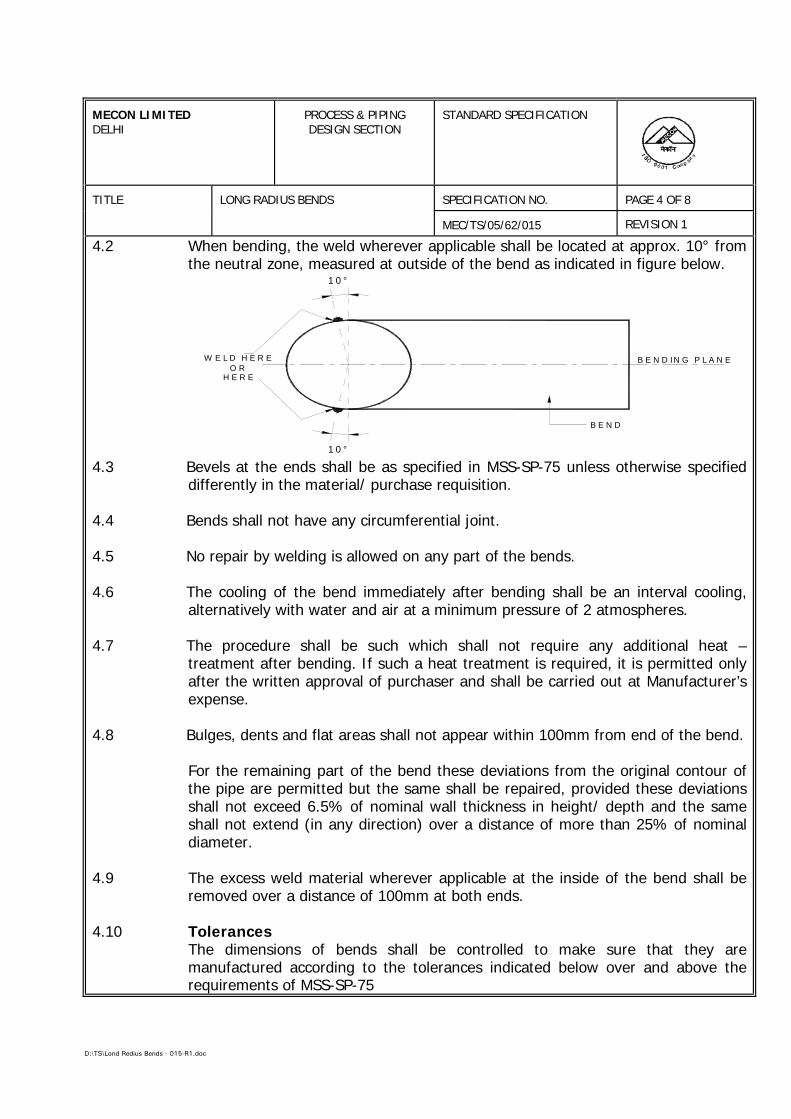
D:\TS\Lond Redius Bends - 015-R1.doc
MECON LIMITEDDELHI
PROCESS & PIPINGDESIGN SECTION
STANDARD SPECIFICATION
TITLE LONG RADIUS BENDS SPECIFICATION NO. PAGE 4 OF 8
MEC/TS/05/62/015 REVISION 1
4.2 When bending, the weld wherever applicable shall be located at approx. 10° fromthe neutral zone, measured at outside of the bend as indicated in figure below.
1 0 °
W E L D H E R EO R
H E R E
B E N D
B E N D IN G P L A N E
1 0 °
4.3 Bevels at the ends shall be as specified in MSS-SP-75 unless otherwise specifieddifferently in the material/ purchase requisition.
4.4 Bends shall not have any circumferential joint.
4.5 No repair by welding is allowed on any part of the bends.
4.6 The cooling of the bend immediately after bending shall be an interval cooling,alternatively with water and air at a minimum pressure of 2 atmospheres.
4.7 The procedure shall be such which shall not require any additional heat –treatment after bending. If such a heat treatment is required, it is permitted onlyafter the written approval of purchaser and shall be carried out at Manufacturer’sexpense.
4.8 Bulges, dents and flat areas shall not appear within 100mm from end of the bend.
For the remaining part of the bend these deviations from the original contour ofthe pipe are permitted but the same shall be repaired, provided these deviationsshall not exceed 6.5% of nominal wall thickness in height/ depth and the sameshall not extend (in any direction) over a distance of more than 25% of nominaldiameter.
4.9 The excess weld material wherever applicable at the inside of the bend shall beremoved over a distance of 100mm at both ends.
4.10 TolerancesThe dimensions of bends shall be controlled to make sure that they aremanufactured according to the tolerances indicated below over and above therequirements of MSS-SP-75
D:\TS\Lond Redius Bends - 015-R1.doc
MECON LIMITEDDELHI
PROCESS & PIPINGDESIGN SECTION
STANDARD SPECIFICATION
TITLE LONG RADIUS BENDS SPECIFICATION NO. PAGE 5 OF 8
MEC/TS/05/62/015 REVISION 1
4.10.1 Minimum Inside Diameter : -2.5% of inside nominaldiameter except 200mm from ends
Bend Angle : ±1°
Bend Radius : ± 1% of bending nominalDiameter
4.10.2 The manufacturer shall check the wall thickness of the pipe before and afterbending along the outside radius either at distances approximately equal topipe diameter or 300mm whichever is less. The measured wall thickness shallbe atleast equal to :
tmin = 0.95 (tnom. - t)
tnom = nominal wall thickness as specified in thematerial/ purchase requisition.
t = 0.35mm for a wall thickness smaller than10mm.
t = 0.50mm for a wall thickness 10mm or more.
4.10.3 Ovality may be defined as :
OD max. – OD min OD nom.
The above value shall be < 1% within 100mm from each end and < 6% forremaining part of the bend. The measurement shall be made over thecircumference of the bend either at distance approximately equal to pipediameter or 300mm whichever is less.
4.10.4 Wrinkles
Measurements of the outside diameter shall be taken in the plane of the bendat locations where wrinkles are present (OD max.) and at locations wherewrinkles are not present (OD min,). The acceptance limit shall be as definedbelow.
OD max. – OD min------------------------- < 1%
OD nom.
D:\TS\Lond Redius Bends - 015-R1.doc
MECON LIMITEDDELHI
PROCESS & PIPINGDESIGN SECTION
STANDARD SPECIFICATION
TITLE LONG RADIUS BENDS SPECIFICATION NO. PAGE 6 OF 8
MEC/TS/05/62/015 REVISION 1
5.0 INSPECTION AND TESTS
5.1 The manufacturer shall perform all inspection and tests as per therequirements of this specification and MSS-SP-75 prior to shipment at hisworks. Such inspection and tests shall be, but not limited to, the following :
a) Verify that the unfinished product arriving at manufacturer’s shop is infull compliance with the pipe specification as referred in para 3.1.
b) Visual Inspection.c) Dimensional and tolerances check as per MSS-SP-75 and requirements
of section 4.0 of this specification.d) Check heat treatment, if carried out, as required and maintain its
records.e) Temperature against time recorder charts for each induction heating.f) Material properties shall be checked to meet the requirements of section
3.0 of this specification.g) The non-destructive inspection on the finished bend shall be carried out
as given below :
• All longitudinal seam welds shall be fully radiographed andacceptance limits shall be as per pipe specification as referred inpara 3.1.
• The full circumference of both ends of each bend after bevellingshall be ultrasonically tested for laminations over a length of 25mmand acceptance limits shall be as per pipe specification as referred inpara 3.1.
5.2 Purchaser’s Representative reserves the right to perform stagewise inspectionand witness tests on all bends as indicated in para 5.1 at Manufacturer’sworks, prior to shipment.
Manufacturer shall give reasonable notice of time and shall provide withoutcharge reasonable access and facilities required for inspection, to thePurchaser’s Representative. Inspection and test performed or witnessed byPurchaser’s Representative shall in no way relieve the Manufacturer’sobligation to perform the required inspection and tests. Under nocircumstances any action of the Purchaser’s Representative shall relieve theManufacturer of his responsibility for the material, design, quality andoperation of the equipment.
D:\TS\Lond Redius Bends - 015-R1.doc
MECON LIMITEDDELHI
PROCESS & PIPINGDESIGN SECTION
STANDARD SPECIFICATION
TITLE LONG RADIUS BENDS SPECIFICATION NO. PAGE 7 OF 8
MEC/TS/05/62/015 REVISION 1
5.3 Test Certificates
The Manufacturer shall produce the Certificates (in original) for all, but notlimited to, the following :
a) Certificates of chemical analysis and mechanical tests carried out onpipe and bends separately.
b) Certificates of required non-destructive test inspection.
c) Certificates of heat treatments, if any.
d) Certificates of all other tests as required in this specification.
In case any of the above said certificates are not available during the finalinspection, the supply shall be considered incomplete.
6.0 MARKING, PACKING AND SHIPMENT
6.1 All bends shall be marked as per MSS-SP-75.
6.2 All loose and foreign material i.e. rust, grease, etc. shall be removed frominside and outside of the bends.
6.3 All bends except bevelled ends shall be coated internally and externally with athin film of zinc chromate red oxide paint for protection against corrosionduring transit and storage. The coating shall be easily removable in the field.Manufacturer shall furnish the details for the same.
6.4 Both ends of all bends shall be suitably protected to avoid any damage duringtransit by means of metallic bevel protectors.
6.5 Package shall be marked legibly with suitable marking to indicate thefollowing:
a) Order Numberb) Package Numberc) Manufacturer’s Named) Size (Inches) and wall thickness (mm)
D:\TS\Lond Redius Bends - 015-R1.doc
MECON LIMITEDDELHI
PROCESS & PIPINGDESIGN SECTION
STANDARD SPECIFICATION
TITLE LONG RADIUS BENDS SPECIFICATION NO. PAGE 8 OF 8
MEC/TS/05/62/015 REVISION 1
7.0 WARRANTY
Purchaser will be reimbursed by Manufacturer for any bend furnished on thisorder that fails under field hydrostatic test if such failure is caused by a defectin the bend which is outside the acceptance limits of this specification. Thereimbursement cost shall include bend cost, labour cost and equipment rentalfor searching, excavation, cutting out and installation of replaced bend inposition. The field hydrostatic test pressure will not exceed that value whichwill cause a calculated hoop stress equivalent to 100% of specified minimumyield strength of the attached pipe.
8.0 DOCUMENTATION
8.1 All documents shall be in English language.
8.2 At the time of bidding, bidder shall submit the following documents :
a) Reference list of previous supplies of bends of similar specifications.
b) Clause-wise list of deviation from this specification, if any.
c) Brief description of manufacturing and quality control facilities of theManufacturer’s works.
8.3 Within one week of placement of order the Manufacturer shall submit fourcopies, of the manufacturing process and quality assurance plan for pipe andbends.
Once the approval has been given by Purchaser any change in material andmethod of manufacture and quality control shall be notified to Purchaserwhose approval in writing of all such changes shall be obtained before thebends are manufactured.
8.4 Within four weeks from the approval date Manufacturer shall submit onereproducible and six copies of the documents as stated in para 8.3 of thisspecification.
8.5 Prior to shipment, the Manufacturer shall submit one reproducible and sixcopies of test certificates as listed in para 5.3 of this specification.
D:\TS\Insulating Joints - 09 - TS.doc
SPECIFICATIONFOR
INSULATING JOINTS
SPECIFICATION NO. : MEC/TS/05/62/009, Rev-0
MECON LIMITEDDELHI - 110 092
MECON LIMITEDREGD. OFF RANCHI
PROCESS & PIPINGDESIGN SECTION
NEW DELHI
STANDARD SPECIFICATIONINSULATING JOINTS
TECHNICAL SPECIFICATION NO. : MEC/TS/05/62/009 REV-0 Page 1 of 10
D:\TS\Insulating Joints - 09 - TS.doc
C O N T E N T S
Sl.No. Description
1.0 SCOPE
2.0 REFERENCE DOCUMENTS
3.0 MATERIALS
4.0 DESIGN & CONSTRUCTION REQUIREMENTS
5.0 INSPECTION AND TESTS
6.0 TEST CERTIFICATES
7.0 PAINTING, MARKING AND SHIPMENT
8.0 GUARANTEE
9.0 DOCUMENTATION
PREPARED BY CHECKED BY APPROVED BY
MECON LIMITEDREGD. OFF RANCHI
PROCESS & PIPINGDESIGN SECTION
NEW DELHI
STANDARD SPECIFICATIONINSULATING JOINTS
TECHNICAL SPECIFICATION NO. : MEC/TS/05/62/009 REV-0 Page 2 of 10
D:\TS\Insulating Joints - 09 - TS.doc
1.0 SCOPE
This specification cover the basic requirements for design manufacture, testingand supply of carbon steel insulating joints to be installed in onshore pipelinesystems handling hydrocarbons in liquid or gaseous phase including LiquifiedPetroleum Gas (LPG).
2.0 REFERENCE DOCUMENTS
2.1 Reference has been made in this specification to the latest edition of, thefollowing Codes, Standards and Specifications.
a) ASME B 31.8 Gas Transmission & Distribution pipingSystem
b) ASME B 31.4 Liquid transportation systems forhydrocarbons, LPG, Anhydrous Ammonia andAlcohols
c) ASTM A 370 Mechanical testing of Steel Product
d) ANSI B 16.25 Butt Welding Ends
e) ASME Section Boiler & pressure Vessel Code viii & ix
f) API 1104 Standard for welding pipelines and Relatedfacilities.
g) SSPC-VIS-1 Steel Structures painting Council VisualStandard.
h) MSS-SP-53 Quality standard for steel castings andforgings for valves flanges and fittings andother piping components - magnetic particleexamination method.
i) MSS-SP-75 Specification for high test wrought weldingfittings.
MECON LIMITEDREGD. OFF RANCHI
PROCESS & PIPINGDESIGN SECTION
NEW DELHI
STANDARD SPECIFICATIONINSULATING JOINTS
TECHNICAL SPECIFICATION NO. : MEC/TS/05/62/009 REV-0 Page 3 of 10
D:\TS\Insulating Joints - 09 - TS.doc
j) NACE RP 0286 The electrical isolation of cathodicallyprotected pipelines.
2.2 In case of conflict between the requirements of this specification and any code,Standard or Specification referred to in this Specification, the requirements ofthis specification shall govern.
3.0 MATERIALS
3.1 Material for the pressure containing parts of the insulating joints shall be asindicated in the data sheets. Material for pups shall be equivalent or superior tothe material of connecting pipeline which is indicated in the data sheets. Otherpart shall be as per manufacturer's standard suitable for the service conditionindicated in Insulating Joint Data Sheets and shall be subject to approval bypurchaser.
3.2 Insulating joints which are subject to field welding by purchaser, shall havecarbon equivalent (CE) not exceeding 0.45 based on check analysis for each heatof steel calculated according to the following formula :
CE = C + Mn/6 + (Cr+Mo+V)/5 + (Ni +Cu)/15
3.3 When specified in the IJ Data Sheet, charpy V-notch test shall be conducted oneach heat of base material, weld metal and heat affected zone of all pressurecontaining parts such as body, welding ends in accordance with the impact testprovisions of ASTM A 370 at a temperature of 0° C. The charpy impact testspecimens shall be taken in the direction of principal grain flow and notchedperpendicular to the original surface of the plate of forging. Average impactenergy value of three full sized specimens shall be 27 joules. Minimum impactenergy value of any one specimen shall not be less than 80% of the averageimpact energy specified. No specimen shall exhibit less than 80% shear area.
3.4 Carbon steel used for the manufacture shall be fully killed
3.5 When specified in data sheet, hardness test shall be carried out as per ASTMA370 for each heat of steel used. The maximum hardness of base metal, weldmetal and heat affected zone of all pressure parts shall be 248 HV10, unlessspecified otherwise.
MECON LIMITEDREGD. OFF RANCHI
PROCESS & PIPINGDESIGN SECTION
NEW DELHI
STANDARD SPECIFICATIONINSULATING JOINTS
TECHNICAL SPECIFICATION NO. : MEC/TS/05/62/009 REV-0 Page 4 of 10
D:\TS\Insulating Joints - 09 - TS.doc
3.6 Insulation material shall be minimum 20 mm thick and shall comply section 5,NACE RP 0286.
4.0 DESIGN & CONSTRUCTION REQUIREMENTS
4.1 Mechanical
4.1.1 Insulating joints shall be of integral type fabricated by welding and with pups oneither side as shown in data sheet. A corrosion allowance as indicated in datasheet shall be considered in design. Bolted and threaded joints are notacceptable.
4.1.2 All materials used for the manufacture of the insulating joint shall be inaccordance with clause 3.0 of this Specification.
4.1.3 Insulating joints shall be designed using the design principles of ASME Section-VIII Div. 1. The design shall be checked for the following two cases :
Case-I : Design Pressure (as per Data Sheet) + Axial Force (F)
The Axial force shall be calculated as under :
F = 0.1 x S x A
Where
S = SMYS of connected pipe (refer Data Sheet)A = Metal cross-sectional area of connected pipe.
The allowable stress in this case shall be less than or equal to 0.5 x SMYS ofinsulating joint material.
Case-II : Hydrostatic Test Pressure
The allowable stress in this case shall be less than or equal to 90% of SMYS ofinsulating joint material.
All design parameters shall be as per Insulating Joint Data Sheet. Detailedcalculations shall be submitted for Purchaser approval.
MECON LIMITEDREGD. OFF RANCHI
PROCESS & PIPINGDESIGN SECTION
NEW DELHI
STANDARD SPECIFICATIONINSULATING JOINTS
TECHNICAL SPECIFICATION NO. : MEC/TS/05/62/009 REV-0 Page 5 of 10
D:\TS\Insulating Joints - 09 - TS.doc
4.1.4 Insulating joint design and materials shall be capable of being vacuum tested to1 millibar.
4.1.5 The joint between pipe pup pieces and main forging shall be full penetration buttweld type. Weld design shall be such as resulting in a weld joint factor of 1.0.
4.1.6 Butt weld ends shall have ends as per ASME B16.25. However, end preparationfor butt welding ends having unequal thickness with respect to connecting pipe,shall be as per ASME B31.4/ B31.8 as applicable.
4.1.7 The reinforcement of inside weld seam, in case pups fabricated from LSAWpipes, shall be removed for a distance of at least 50mm from each end.
4.1.8 Insulating joints shall allow free passage of scraper/ instrumented pigs. Theinternal bore shall be same as that of connecting pipe including its tolerances.
4.1.9 The insulating joint shall be formed by sandwiching and locking in positions theinsulating material in a bell and spigot type of joint. The joint shall be assembledin such a way that its various components are firmly locked in position and thecompleted joint is capable of withstanding stresses due to designed operatingconditions and field hydrostatic testing.
4.1.10 Insulating joints shall be suitable for aboveground or underground installationsas indicated in the data sheets.
4.1.11 All welds shall be made by welders and welding procedures qualified inaccordance with the provisions ASME section IX. The procedure qualificationshall include impact test and hardness test and shall meet the requirements ofclause 3.3, 3.5 of this specification.
4.1.12 Repair welding on parent metal is not allowed. Repair of welds shall be carriedout only after specific approval by purchaser's representative for each repair.The repair welding shall be carried out by welders and welding procedures dulyqualified as per ASME section IX and records for each repair shall be maintained.
4.1.13 Internal diameter at the welding end shall not vary more than + 1, -3 mm fromthe nominal internal diameter.
MECON LIMITEDREGD. OFF RANCHI
PROCESS & PIPINGDESIGN SECTION
NEW DELHI
STANDARD SPECIFICATIONINSULATING JOINTS
TECHNICAL SPECIFICATION NO. : MEC/TS/05/62/009 REV-0 Page 6 of 10
D:\TS\Insulating Joints - 09 - TS.doc
4.1.14 Out of roundness measured at the root face of the welding ends shall not bemore than 0.5% of the specified inside diameter.
4.2 Electrical
4.2.1 The average dielectric strength of the insulating joint shall be minimum 15 kiloVolts.
4.2.2 Two cleats as shown in data sheet shall be provided on the pups on either sideof the insulating joint for connecting 10 mm2 and 50 mm2 cables formeasurement/ shorting purposes. Cleats shall be attached to the insulating jointby welding.
5.0 INSPECTION AND TESTS
5.1 The manufacture, shall perform all inspection and tests as per the requirementsof this specification and the relevant codes, prior to shipment at his works. Suchinspection and tests shall be, but not limited to the following:
5.1.1 All insulating joints shall be visually inspected.
5.1.2 Dimensional checks shall be carried out as per the purchaser approved drawings.
5.1.3 Chemical composition and mechanical properties including hardness shall bechecked as per relevant material standards and this specification, for each heatof steel used.
5.1.4 Non-destructive inspection of insulating joints shall be carried out as givenbelow:
a) 100% radiography shall be carried out on all butt & repair welds ofpressure containing parts. Acceptance limits shall be as per API 1104.
Welds which in purchaser's Representative opinion can not be inspectedby radiographic methods,shall be checked by ultrasonic or magneticparticle methods. Acceptance criteria shall be as per ASME Section VIIIAppendix-12 and Appendix-6 respectively.
MECON LIMITEDREGD. OFF RANCHI
PROCESS & PIPINGDESIGN SECTION
NEW DELHI
STANDARD SPECIFICATIONINSULATING JOINTS
TECHNICAL SPECIFICATION NO. : MEC/TS/05/62/009 REV-0 Page 7 of 10
D:\TS\Insulating Joints - 09 - TS.doc
b) All finished weld ends shall be 100% ultrasonically tested for laminationtype defects for a distance of 5Omm from the ends. Any laminationlarger than 6.35 mm shall not be acceptable.
c) All forgings shall be wet magnetic particle inspected on 100% of forgedsurfaces. Method and acceptance shall comply MSS-SP-53.
d) All fillet weld of thickness < 6mm shall be examined 100% by magneticparticle inspection and ≥ 6mm shall be examined 100% by UT.Accetpance criteria for MPI & UT shall be as per ASME Sec.VIII Appendix-6 & Appendix-12 respectively.
5.1.5 Insulating joint shall be hydrostatically tested to a pressure as indicated in datasheet. The test duration shall be of 15 minutes.
5.1.6 After the hydrostatic test insulating joints shall be tested with air at 5 kg/cm2 for10 minutes. The tightness shall be checked by immersion or with a frothingagent. No leakage will be accepted.
5.1.7 Dielectric Test
a) Insulation resistance of each insulating joint shall be atleast 25 mega-ohms when checked with 500-1000 V DC.
b) Insulating joint before and after the hydrostatic test, shall be tested fordielectric integrity for one minute at 5000 V A.C., 50 cycles and theleakage current before and after hydrostatic test shall be equal. Testingtime voltage and leakage shall be recorded and certified. No repair shallbe permitted to the insulating joints failed in the above mentioned tests.
5.2 Purchaser reserves the right to perform stagewise inspection and witness test asindicated in Para 5.1 at Manufacturer's works prior to shipment. Manufacturershall give reasonable notice of time and shall provide without charge reasonableaccess and facilities required for inspection to the purchaser's Representative .
Inspection and tests performed/witnessed by the Purchaser's Representativeshall in no way relieve the Manufacturer's obligation to perform the requiredinspection and test.
MECON LIMITEDREGD. OFF RANCHI
PROCESS & PIPINGDESIGN SECTION
NEW DELHI
STANDARD SPECIFICATIONINSULATING JOINTS
TECHNICAL SPECIFICATION NO. : MEC/TS/05/62/009 REV-0 Page 8 of 10
D:\TS\Insulating Joints - 09 - TS.doc
6.0 TEST CERTIFICATES
6.1 Manufacturer shall submit following certificates to Purchaser's Representative.
a) Test certificates relevant to the chemical analysis and mechanicalproperties including hardness of the materials used for construction ofinsulating joint as per this specification and relevant standards.
b) Test reports on non-destructive testing.
c) Test certificates for hydrostatic and air tests.
d) Test certificate for electrical test.
e) Test report on vacuum test.
7.0 PAINTING, MARKING AND SHIPMENT.
7.1 Insulating joint surface shall be thoroughly cleaned, freed from rust and greaseand applied with sufficient coats of corrosion resistant paint. Surface preparationshall be carried out by shot blasting to SP-6 in accordance with "steel structurespainting council - Visual standard SSPC-VIS-l.". External surfaces of burriedinsulating joints shall be painted with three coats of suitable coal tar epoxy resinwith a minimum dry film thickness of 300 microns.
Manufacturer shall indicate the type of corrosion resistant paint used, in thedrawings submitted for approval.
7.2 Insulating joints shall be marked with indelible paint with the following data:-
a. Manufacturer's name
b. Suitable for inch nominal diameter pipeline
c. End thickness in mm
d. Material
e. Design Pressure/ Hydrostatic Test Pressure
MECON LIMITEDREGD. OFF RANCHI
PROCESS & PIPINGDESIGN SECTION
NEW DELHI
STANDARD SPECIFICATIONINSULATING JOINTS
TECHNICAL SPECIFICATION NO. : MEC/TS/05/62/009 REV-0 Page 9 of 10
D:\TS\Insulating Joints - 09 - TS.doc
f. ANSI Class Ratingg. Tag No.h. Year of Manufacture
7.3 Insulating joints shall be suitably protected to avoid any damage during transit.Metallic bevel protectors shall be provided to weld ends.
7.4 Only those insulating joints which have been inspected and certified byPurchaser shall be shipped.
8.0 GUARANTEE
8.1 The manufacturer shall guarantee that the materials used comply with therequirements of this specification.
8.2 Manufacturer shall replace or repair insulating joints found defective due toinadequate engineering or quality of material.
8.3 Manufacturer shall replace the insulating joint without delay if the defect ormalfunctioning can not be eliminated.
8.4 Any defects occurring within 12 months from the date of installation or within 30months from the date of despatch, whichever is earlier, shall be repaired makingall necessary modifications and repair of defective parts free of charge to thepurchaser.
9.0 DOCUMENTATION
9.1 All documents shall be in English Language.
9.2 At the time of bidding, Bidder shall submit the following documents:-
a) General arrangement drawing along with cross sectional view, overalldimensions and details of insulating meterials recommended.
b) Reference lists of previous supplies of insulating joint of similarspecification.
MECON LIMITEDREGD. OFF RANCHI
PROCESS & PIPINGDESIGN SECTION
NEW DELHI
STANDARD SPECIFICATIONINSULATING JOINTS
TECHNICAL SPECIFICATION NO. : MEC/TS/05/62/009 REV-0 Page 10 of 10
D:\TS\Insulating Joints - 09 - TS.doc
c) Clausewise list of deviation from this specification, if any.
9.3 Within three weeks of placement of order, the Manufacturer shall submit fourcopies of but not limited to the following drawings, documents and specificationsfor approval.
a) Fabrication drawings and relevant calculations for pressure containingparts.
b) Welding procedure and method of manufacture for all phases ofmanufacture.
c) Quality Assurance Plan (QAP)
Once the approval has been given by purchaser any changes in design, materialand method of manufacture shall be notified to the Purchaser whose approval inwriting of all changes shall be obtained before the insulting joint aremanufactured.
9.4 Within four weeks from the approval date Manufacturer shall submit onereproducible and six copies of the approved drawings, documents andspecifications as listed in 9.3 of this specification.
9.5 Prior to shipment, the manufacturer shall submit one reproducible and six copiesof the test certificates as listed in Clause 6.0 of this specification.
D:\TS\Specification for Split Tee (011A) - R1.doc
PROCESS & PIPING DESIGN SECTIONMECON LIMITEDDELHI – 110 092
STANDARD SPECIFICATIONFOR
SPLIT TEES(HOT TAP MATERIAL)
SPECIFICATION NO. : MEC/TS/05/62/011A, Rev-1
MECON LIMITEDREGD. OFF RANCHI
PROCESS & PIPINGDESIGN SECTION
NEW DELHI
STANDARD SPECIFICATIONSPLIT TEES (HOT TAPPING
MATERIAL)
TECHNICAL SPECIFICATION NO. : MEC/TS/05/62/011A REV-1 Page 1 of 8
D:\TS\Specification for Split Tee (011A) - R1.doc
C O N T E N T S
Sl.No. Description
1.0 SCOPE
2.0 REFERENCE DOCUMENTS
3.0 MANUFACTURER'S QUALIFICATION
4.0 MATERIALS
5.0 DESIGN AND CONSTRUCTION REQUIREMENTS
6.0 INSPECTION AND TESTS
7.0 TEST CERTIFICATES
8.0 PAINTING, MARKING AND SHIPMENT
9.0 WARRANTY
10.0 DOCUMENTATION
1 May,05
0 Jan,05
Rev Date Prepared By Checked By Approved By
MECON LIMITEDREGD. OFF RANCHI
PROCESS & PIPINGDESIGN SECTION
NEW DELHI
STANDARD SPECIFICATIONSPLIT TEES (HOT TAPPING
MATERIAL)
TECHNICAL SPECIFICATION NO. : MEC/TS/05/62/011A REV-1 Page 2 of 8
D:\TS\Specification for Split Tee (011A) - R1.doc
1.0 SCOPE
This specification covers the basic requirements for the design, manufacture andsupply of carbon steel split tees as hot tap material to be installed in pipeline systemfor handling hydrocarbons in liquid or gaseous phase.
2.0 REFERENCE DOCUMENTS
Reference has also been made in this specification to the latest edition of thefollowing codes, standards and specifications :
a) ASME B 31.4 : Liquid Transportation Systems for Hydrocarbons,Liquid Petroleum Gas, Anhydrous Ammonia andAlcohols.
b) ASME B 31.8 : Gas Transmission and Distribution Piping System
c) ASME B 16.5 : Steel Pipe Flanges & Flanged Fittings
d) ASME B 16.9 : Factory made wrought steel butt welding fittings.
e) ASME B 16.25 : But Welding Ends
f) ASME Sec. VIII : Boiler & Pressure Vessels Code-Rules for theconstruction of pressure vessels.
g) ASME Sec. IX : Boiler & Pressure Vessel Code-Welding & BrazingQualifications.
h) ASTM A 370 : Mechanical Testing of Steel Products
i) MSS-SP-44 : Steel Pipe Flanges
j) MSS-SP-53 : Quality Standard for Steel Castings and Forgings forValves, Flanges and fittings and other Pipingcomponents and - Magnetic Particle ExaminationMethod.
k) MSS-SP-75 : Specification for High Test Wrought Butt WeldingFittings
l) API 1104 : Specification for Welding Pipeline and RelatedFacilities
MECON LIMITEDREGD. OFF RANCHI
PROCESS & PIPINGDESIGN SECTION
NEW DELHI
STANDARD SPECIFICATIONSPLIT TEES (HOT TAPPING
MATERIAL)
TECHNICAL SPECIFICATION NO. : MEC/TS/05/62/011A REV-1 Page 3 of 8
D:\TS\Specification for Split Tee (011A) - R1.doc
m) SSPC-VIS-1 : Steel Structures Painting Council
In case of conflict between the requirement of this specification and the codes,standards and specifications referred above, the requirements of thisspecification shall govern.
3.0 MANUFACTURER'S QUALIFICATION
Manufacturer who intend bidding for fittings should possess the records of asuccessful proof test for split tees qualifying the ranges of sizes quoted, inaccordance with the provisions of ASME B16.9/ MSS-SP-75. These records shallbe submitted on demand by Client/ Consultant before or after placement oforder.
4.0 MATERIALS
4.1 The basic materials required for manufacturing of split tees have been indicatedin the data sheet. Other additional materials required for manufacturing splittees shall be as per manufacturer's standard suitable for the service conditionsindicated in data sheet and shall be subjected to approval by Purchaser.
4.2 Fully killed Carbon steel shall be used in the manufacture of split tees.
4.3 Each heat of steel used for the manufacture of pressure containing parts of theflow tees shall have carbon equivalent (CE) not greater than 0.45 calculated fromthe check analysis in accordance with the following formula.
CE = C + Mn/6 + (Cr+Mo+V)/5 + (Ni +Cu)/15
Carbon content on check analysis shall not exceed 0.22%.
4.4 When specified in Data sheet, Charpy V-notch test shall be conducted for eachheat of steel used in manufacture of split tee. Test shall conform to theprovisions of ASTM A-370 and at a temperature of -20°C. The Charpy impact testspecimen shall be taken in the direction of principal grain flow and notchedperpendicular to the original surface of the plate or forging. The average impactenergy values of full sized three specimens shall be 27 Joules, unless indicatedotherwise in the data sheets :
MECON LIMITEDREGD. OFF RANCHI
PROCESS & PIPINGDESIGN SECTION
NEW DELHI
STANDARD SPECIFICATIONSPLIT TEES (HOT TAPPING
MATERIAL)
TECHNICAL SPECIFICATION NO. : MEC/TS/05/62/011A REV-1 Page 4 of 8
D:\TS\Specification for Split Tee (011A) - R1.doc
Minimum impact energy value of any one specimen of the three specimensanalysed shall not be less than 80% of the above average values.
4.5 When specified in the data sheet, hardness test shall be carried out as per ASTMA 370 for each heat of steel used. A full thickness cross section shall be takenfor this purpose and the maximum hardness of base metal, weld metal and HAZof all pressure containing parts shall not exceed 248 HV10, unless otherwisespecified.
5.0 DESIGN AND CONSTRUCTION REQUIREMENTS
5.1 Split tees shall be designed and manufactured in accordance with the provisionsof codes and standards referred in Section 2.0 of this specification. Flanges uptosize 16” shall conform to the requirements of ASME B16.5. Design factor andcorrosion allowance indicated in data sheet shall be taken into account for designof split-tees.
5.2 Split tees shall generally conform to the figure shown in the data sheet and shallmeet following requirements as minimum :
a) Sleeves shall be designed to meet pressure & reinforce requirements ofASME Codes.
b) Fittings shall be manufactured with controlled carbon equivalent for itswelding in harsh out side environments.
c) Split tee shall be of full branch or reducing branch & meet therequirement for fittings with hot tap machine.
5.3 Butt weld ends shall be beveled as per MSS-SP-75/ B16.25.
5.4 Split tees shall be manufactured by hot drawn, full branch/ reduced branchopening, snug-fitting sleeve or fabricated full size nipple, branch outlet welded tosnug-fittings sleeve.
5.5 All welds shall be made by welders and welding procedures qualified inaccordance with ASME Section-IX. The welding procedure qualification test shallinclude charpy impact test and hardness test and shall meet the requirements ofclause 4.3 and 4.5 of this specification respectively.
MECON LIMITEDREGD. OFF RANCHI
PROCESS & PIPINGDESIGN SECTION
NEW DELHI
STANDARD SPECIFICATIONSPLIT TEES (HOT TAPPING
MATERIAL)
TECHNICAL SPECIFICATION NO. : MEC/TS/05/62/011A REV-1 Page 5 of 8
D:\TS\Specification for Split Tee (011A) - R1.doc
5.6 Repair by welding on parent metal is not allowed. Repair of welds shall becarried out only after specific approval by Purchaser's Representative for eachrepair. The repair welding shall be carried out by the welders and weldingprocedures duly qualified as per ASME Section-IX and records for each repairshall be maintained.
6.0 INSPECTION AND TESTS
6.1 The manufacturer shall perform all inspections and tests as per the requirementsof this specification and the relevant codes, prior to shipment, at his works. Suchinspection and tests shall be, but not limited to the following :
6.1.1 All split tee shall be visually inspected.
6.1.2 Dimensional checks shall be carried out as per the approved drawing.
6.1.3 Chemical composition and Mechanical properties shall be checked as per MSS-SP-75 and this specification for each heat of steel used.
6.1.4 Non destructive examination of individual split tees shall be performed as givenbelow:
a) 100% inspection by radiography shall be carried out on all pressurecontaining welds on fittings. Acceptance limits shall be as per API 1104.
b) Welds which in Purchaser's Representative's opinion cannot be inspectedby radiographic methods shall be checked by ultrasonic or magneticparticle methods. Acceptance criteria shall be as per ASME Section VIIIAppendix-12 and Appendix-6 respectively.
c) All finished wrought weld ends shall be 100% ultrasonically tested forlamination type defects for a distance of 25mm from the end. Anylamination larger than 6.35mm shall not be acceptance.
d) All forgings shall be wet magnetic particle examined on 100% of theforged surfaces. Method and acceptance shall comply with MSS-SP-53.
MECON LIMITEDREGD. OFF RANCHI
PROCESS & PIPINGDESIGN SECTION
NEW DELHI
STANDARD SPECIFICATIONSPLIT TEES (HOT TAPPING
MATERIAL)
TECHNICAL SPECIFICATION NO. : MEC/TS/05/62/011A REV-1 Page 6 of 8
D:\TS\Specification for Split Tee (011A) - R1.doc
6.2 Purchaser's Representative shall also perform stagewise inspection and witnesstests as indicated in clause 6.1 at manufacturer's works prior to shipment.Manufacturer shall give reasonable notice of time and shall provide withoutcharge reasonable access and facilities required for inspection, to the Purchaser'sRepresentative.
Inspection and tests performed/ witnessed by Purchaser's Representative shall inno way relieve the Manufacturer's obligation to perform the required inspectionand tests.
7.0 TEST CERTIFICATES
7.1 Manufacturer shall submit following certificates to Purchaser's Representative :
a) Test certificates relevant to the chemical analysis and mechanicalproperties of the materials used for construction as per this specificationand relevant standards.
b) Test reports on radiographic and ultrasonic inspection and wet magneticparticle examination.
c) Certificates for each split tee stating that it is capable of withstandingwithout leakage for a test duration of 15 minutes and test pressure whichresults in a hoop stress equivalent to 90% of the specified minimum yieldstrength and for the pipe with which the split tee is to be attached withoutimpairing its serviceability.
d) Test reports on heat treatment carried out.
8.0 PAINTING, MARKING AND SHIPMENT
8.1 Split tees entire surface shall be thoroughly cleaned, freed from rust and greaseand applied with sufficient coats of corrosion resistant paint, after all the requiredtests have been performed and accepted by Purchaser's Representative. Thesurface preparation shall be carried out by shot blasting to SP 6 in accordancewith "Steel Structures Painting Council - Visual Standard - SSPC-VIS-1".
8.2 Manufacturer shall indicate the type & recommended coats of corrosion resistantpaint used, in the drawing submitted for approval.
MECON LIMITEDREGD. OFF RANCHI
PROCESS & PIPINGDESIGN SECTION
NEW DELHI
STANDARD SPECIFICATIONSPLIT TEES (HOT TAPPING
MATERIAL)
TECHNICAL SPECIFICATION NO. : MEC/TS/05/62/011A REV-1 Page 7 of 8
D:\TS\Specification for Split Tee (011A) - R1.doc
8.3 Split tees shall be marked with indelible paint with the following data :
a) Manufacturer's Nameb) Nominal diameter in inches D1 x D2c) End thickness in mm T1 x T2d) Materiale) Tag numbers
8.4 Split tees shall be suitably protected to avoid any damage during transit. Metallicor high impact plastic bevel protectors shall be provided for weld ends.
9.0 WARRANTY
Purchaser will be reimbursed by Manufacturer for any Split tee furnished to thisspecification which fails under field hydrostatic testing or does not performsatisfactory during the pigging operation and if such failure or non-performanceis caused by a defect in the Split tees which is outside the acceptance limits ofthis specification. The reimbursement cost shall include cost of Split tee, labourand equipment rental for finding, excavating, cutting, and installation of replacedSplit tee in position.
10.0 DOCUMENTATION
10.1 At the time of bidding, bidder shall submit the following documents :-
a) General arrangement drawing of split tees with overall dimensions andcross sectional drawings.
b) Reference list of previous supplies of split tees of similar specification withrelevant details viz Project, Year of supply, Client, size, Rating and servicefor the last five years.
c) Clausewise list of deviation from this specification, if any.d) Quality Assurance Plan (QAP), data sheets enclosed with the tender
enquiry duly filled in/ stamped and signed by the Bidder.
10.2 Within two weeks of placement of order, the manufacturer shall submit fourcopies, of but not limited to, the following drawings, documents andspecifications for approval.
a) Fabrication drawings and relevant calculations for pressure containingparts.
MECON LIMITEDREGD. OFF RANCHI
PROCESS & PIPINGDESIGN SECTION
NEW DELHI
STANDARD SPECIFICATIONSPLIT TEES (HOT TAPPING
MATERIAL)
TECHNICAL SPECIFICATION NO. : MEC/TS/05/62/011A REV-1 Page 8 of 8
D:\TS\Specification for Split Tee (011A) - R1.doc
b) Calculation for fittings thickness.
c) Method of manufacture, welding procedure and heat treatment details.
d) Quality control Manual.
Once the approval has been given by Purchaser, any change in design, materialmethod of manufacture shall be notified to Purchaser whose approval in writingof all changes shall be obtained before the Split tees are manufactured.
10.3 Within four weeks from the approval date Manufacturer shall submit onereproducible and six copies of the approved drawings, documents andspecification as stated in clause 10.2 of this specification.
10.4 Prior to shipment, Manufacturer shall submit one reproducible and six copies oftest certificates as listed in clause 7.0 of this specification.
10.5 All documents shall be in English Language.
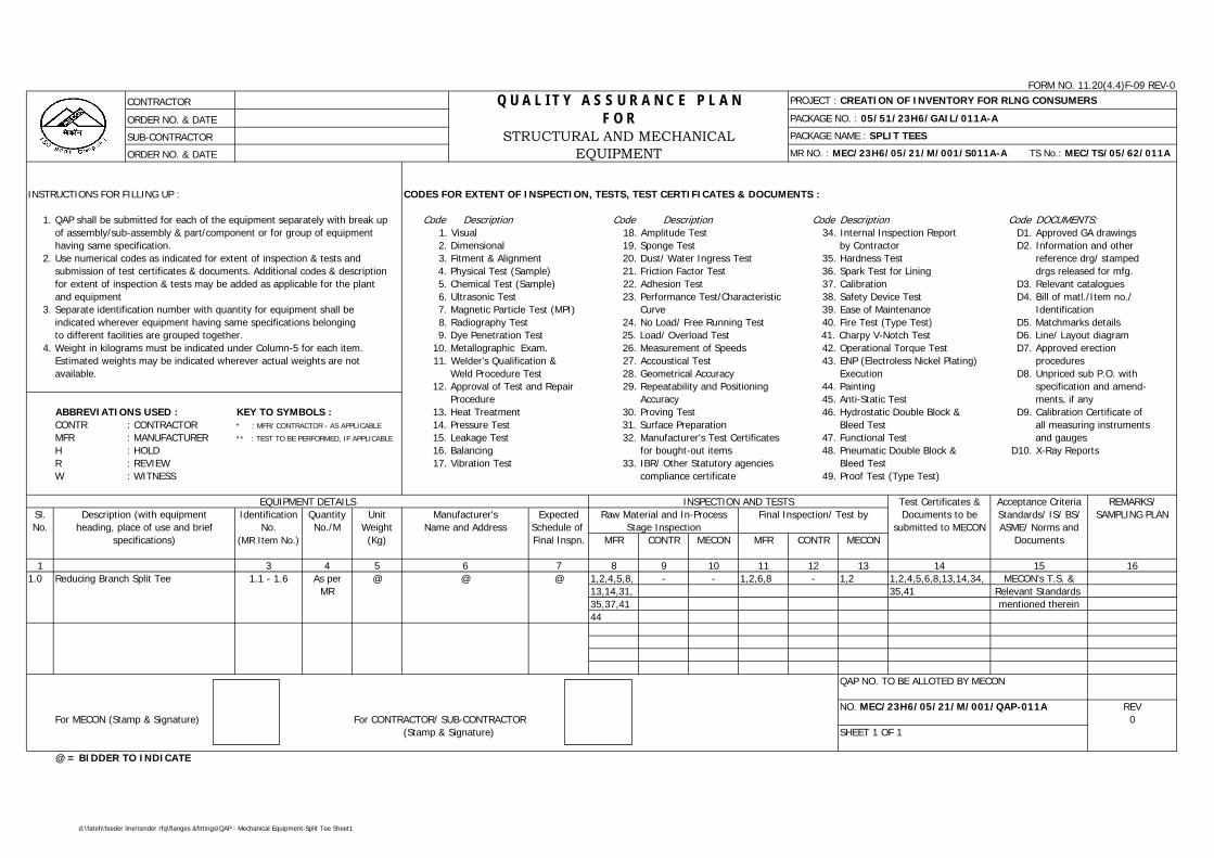
FORM NO. 11.20(4.4)F-09 REV-0
CONTRACTOR PROJECT : CREATION OF INVENTORY FOR RLNG CONSUMERS
ORDER NO. & DATE PACKAGE NO. : 05/51/23H6/GAIL/011A-A
SUB-CONTRACTOR PACKAGE NAME : SPLIT TEES
ORDER NO. & DATE MR NO. : MEC/23H6/05/21/M/001/S011A-A TS No.: MEC/TS/05/62/011A
INSTRUCTIONS FOR FILLING UP : CODES FOR EXTENT OF INSPECTION, TESTS, TEST CERTIFICATES & DOCUMENTS :
1. QAP shall be submitted for each of the equipment separately with break up Code Description Code Code Description Code DOCUMENTS:of assembly/sub-assembly & part/component or for group of equipment 1. Visual 18. Amplitude Test 34. Internal Inspection Report D1. Approved GA drawingshaving same specification. 2. Dimensional 19. Sponge Test by Contractor D2. Information and other
2. Use numerical codes as indicated for extent of inspection & tests and 3. Fitment & Alignment 20. Dust/ Water Ingress Test 35. Hardness Test reference drg/ stampedsubmission of test certificates & documents. Additional codes & description 4. Physical Test (Sample) 21. Friction Factor Test 36. Spark Test for Lining drgs released for mfg.for extent of inspection & tests may be added as applicable for the plant 5. Chemical Test (Sample) 22. Adhesion Test 37. Calibration D3. Relevant cataloguesand equipment 6. Ultrasonic Test 23. Performance Test/Characteristic 38. Safety Device Test D4. Bill of matl./Item no./
3. Separate identification number with quantity for equipment shall be 7. Magnetic Particle Test (MPI) Curve 39. Ease of Maintenance Identification indicated wherever equipment having same specifications belonging 8. Radiography Test 24. No Load/ Free Running Test 40. Fire Test (Type Test) D5. Matchmarks detailsto different facilities are grouped together. 9. Dye Penetration Test 25. Load/ Overload Test 41. Charpy V-Notch Test D6. Line/ Layout diagram
4. Weight in kilograms must be indicated under Column-5 for each item. 10. Metallographic Exam. 26. Measurement of Speeds 42. Operational Torque Test D7. Approved erectionEstimated weights may be indicated wherever actual weights are not 11. Welder’s Qualification & 27. Accoustical Test 43. ENP (Electroless Nickel Plating) proceduresavailable. Weld Procedure Test 28. Geometrical Accuracy Execution D8. Unpriced sub P.O. with
12. Approval of Test and Repair 29. Repeatability and Positioning 44. Painting specification and amend-Procedure Accuracy 45. Anti-Static Test ments, if any
ABBREVIATIONS USED : KEY TO SYMBOLS : 13. Heat Treatment 30. Proving Test 46. Hydrostatic Double Block & D9. Calibration Certificate ofCONTR : CONTRACTOR * : MFR/ CONTRACTOR - AS APPLICABLE 14. Pressure Test 31. Surface Preparation Bleed Test all measuring instrumentsMFR : MANUFACTURER ** : TEST TO BE PERFORMED, IF APPLICABLE 15. Leakage Test 32. Manufacturer's Test Certificates 47. Functional Test and gaugesH : HOLD 16. Balancing for bought-out items 48. Pneumatic Double Block & D10. X-Ray ReportsR : REVIEW 17. Vibration Test 33. IBR/ Other Statutory agencies Bleed TestW : WITNESS compliance certificate 49. Proof Test (Type Test)
Test Certificates & REMARKS/Sl. Identification Quantity Unit Expected Documents to be SAMPLING PLANNo. No. No./M Weight Schedule of submitted to MECON
(MR Item No.) (Kg) Final Inspn. MFR CONTR MECON MFR CONTR MECON
1 3 4 5 7 8 9 10 11 12 13 14 161.0 1.1 - 1.6 As per @ @ 1,2,4,5,8, - - 1,2,6,8 - 1,2 1,2,4,5,6,8,13,14,34,
MR 13,14,31, 35,4135,37,4144
QAP NO. TO BE ALLOTED BY MECON
NO. MEC/23H6/05/21/M/001/QAP-011A REVFor MECON (Stamp & Signature) For CONTRACTOR/ SUB-CONTRACTOR 0
(Stamp & Signature) SHEET 1 OF 1
@ = BIDDER TO INDICATE
Relevant Standards mentioned therein
Description
6@
EQUIPMENT DETAILS INSPECTION AND TESTSDescription (with equipment
heading, place of use and briefFinal Inspection/ Test byManufacturer's
Acceptance CriteriaStandards/ IS/ BS/ASME/ Norms and
Documents
15MECON's T.S. &
specifications)
Reducing Branch Split Tee
Name and AddressRaw Material and In-Process
Stage Inspection
Q U A L I T Y A S S U R A N C E P L A NF O R
STRUCTURAL AND MECHANICALEQUIPMENT
d:\fateh\feeder line\tender rfq\flanges &fittings\QAP - Mechanical Equipment-Split Tee Sheet1
D:\TS\PSV - TS - 056 (R-1).doc
PROCESS & PIPING DESIGN SECTIONMECON LIMITEDDELHI – 110 092
TECHNICAL SPECIFICATIONFOR
PRESSURE SAFETY VALVES
SPECIFICATION NO. : MEC/TS/05/62/056, Rev-1
MECON LIMITEDDelhi
PROCESS & PIPINGDESIGN SECTION
TECHNICAL SPECIFICATIONFOR
PRESSURE SAFETY VALVES
TECHNICAL SPECIFICATION NO. : MEC/TS/05/62/056 REV-1 Page 1 of 9
D:\TS\PSV - TS - 056 (R-1).doc
C O N T E N T S
Sl.No. Description Page No.
1.0 GENERAL 2
2.0 VALVE SIZING 5
3.0 VALVE CONSTRUCTION 5
4.0 NAMEPLATE 7
5.0 INSPECTION & TESTING 7
6.0 SHIPPING 9
7.0 GUARANTEE 9
8.0 REJECTION 9
Revision No. Date Revised by Checked by Approved by
1 K.P. Singh A.K. Johri Niraj Gupta
PREPARED BY :
K.P. SINGH
CHECKED BY :
A.K. JOHRI
APPROVED BY :
NIRAJ GUPTA
MECON LIMITEDDelhi
PROCESS & PIPINGDESIGN SECTION
TECHNICAL SPECIFICATIONFOR
PRESSURE SAFETY VALVES
TECHNICAL SPECIFICATION NO. : MEC/TS/05/62/056 REV-1 Page 2 of 9
D:\TS\PSV - TS - 056 (R-1).doc
1.0 GENERAL
1.1 Scope
1.1.1 This specification together with the attached data sheets covers the requirements forthe design, materials, nameplate marking, testing and shipping of pressure safetyvalves.
1.1.2 The related standards referred to herein and mentioned below shall be of the latesteditions prior to the date of the Purchaser's enquiry :
ASME B 1.20.1 : Pipe threads
ASME B 16.5 : Pipe flanges and flanged fittings
ASME B 16.20 : Ring joint gaskets and grooves for steel pipe flanges
ASME Sec.VIII : Boiler & pressure vessels codes for unfired pressure vessel
API RP 520 : Sizing, selection and installation of pressure relieving(Part-I & II) devices in refineries
API RP 521 : Guide for pressure relieving and depressurisingsystems
API 526 : Flanged steel safety-relief valves
API 527 : Commercial seat tightness of refineries relief valvewith metal to metal seats
DIN 50049 : Document on material testing
IBR : Indian boiler regulations
1.1.3 In the event of any conflict between this specification, data sheets, related standards,codes etc, the Vendor should refer the matter to the Purchaser for clarifications andonly after obtaining the same, should proceed with the manufacture of the items inquestion.
1.1.4 Purchaser's data sheets indicate the selected valve's relieving area, materials for thebody, bonnet, disc, nozzle, spring, indicative inlet/outlet connection sizes, bellows etc.However, this does not relieve the Vendor of the responsibility for proper selection withrespect to the following :
MECON LIMITEDDelhi
PROCESS & PIPINGDESIGN SECTION
TECHNICAL SPECIFICATIONFOR
PRESSURE SAFETY VALVES
TECHNICAL SPECIFICATION NO. : MEC/TS/05/62/056 REV-1 Page 3 of 9
D:\TS\PSV - TS - 056 (R-1).doc
a) Sizing calculations and selection of valve with proper relieving area to meet theoperating conditions indicated.
b) Selection of materials for all parts of the valve suitable for the fluid and itsconditions indicated.
1.1.5 All process-wetted parts, metallic and non-metallic, shall be suitable for the fluids andservice specified by the Purchaser. The service gas composition shall be as given inAnnexure-I.
1.2 Bids
1.2.1 Vendor's quotation shall include a detailed specification sheet for each pressure safetyvalve which shall provide all the details regarding type, construction materials, relievingarea, relieving capacity, orifice letter designation, overpressure, blowdown, operatingpressure, etc., and any other valve accessories.
1.2.2 All the units of measurement for various items in the Vendor's specification sheets shallbe to the same standards as those in Purchaser's data sheets.
1.2.3 All the material specifications for various parts in the Vendor's specification sheets shallbe to the same standards as those in Purchaser's data sheets.
1.2.4 Deleted.
1.2.5 Vendor shall enclose catalogues giving detailed technical specifications and otherinformation for each type of pressure safety valve covered in the bid.
1.2.6 Vendor's quotation, catalogues, drawings, operating and maintenance manual, etc.,shall be in English.
1.2.7 Vendor’s quotation shall include detailed sizing calculation for each pressure safetyvalve. Published data for certified discharge coefficient and certified flow capacities andactual discharge area shall be furnished. Data used by Vendor without the abovementioned supported documentation shall, on prima-facie basis, be rejected.
1.2.8 All valves shall have been type tested for capacity as per ASME. A copy of the certificateshall be provided.
1.2.9 Vendor shall also quote separately for the following :
a) Two years recommended operational spares for each pressure relief valve andits accessories. List of such spares without price shall be indicated alongwithtechnical bid and separately with price.
b) Any specific tools needed for maintenance work.
MECON LIMITEDDelhi
PROCESS & PIPINGDESIGN SECTION
TECHNICAL SPECIFICATIONFOR
PRESSURE SAFETY VALVES
TECHNICAL SPECIFICATION NO. : MEC/TS/05/62/056 REV-1 Page 4 of 9
D:\TS\PSV - TS - 056 (R-1).doc
1.2.10 Vendor’s quotation shall include general arrangement and sectional drawings showingall features and major parts with reference numbers and material specification.
IMPORTANT
The drawings to be submitted alongwith the bid shall be in total compliancewith the requirement of technical specification and data sheets of the valveswith no exception & deviation.
1.2.11 Vendor’s quotation shall include Quality Assurance Plan (QAP) enclosed with this tenderduly signed, stamped & accepted.
1.3 Drawings and Data
1.3.1 Detailed drawings, data, catalogues required from the Vendor are indicated by thePurchaser in this specification. The required number or reproducibles and prints shouldbe dispatched to the address mentioned, adhering to the time limits indicated.
1.3.2 Within two weeks of placement of order, Vendor shall submit six copies of certifieddrawings and specification sheets for each pressure safety valve for Purchaser’s finalapproval. These documents shall specially include the following :
a) Flange face to face dimension.b) Height of the complete valve assembly.c) Weight of the complete valve assembly.d) Cold bench set pressure for the valve to be tested at atmospheric temperature
and back pressure.e) The cold test medium to be used for bench test in case it is different from air.f) Horizontal reaction force at center line of valve outlet.g) Relieving capacity of the valve under the same operating conditions.h) Over pressure and blowdown/ reclosing pressure for each valve.
1.3.3 Vendor shall provide test certificates for all the tests indicated in clause 5.0 of thisspecification. In addition Vendor shall provide the Manufacturer’s certificate ofconformity to Purchaser’s specifications as per clause 2.2 of Din 50049.
1.3.4 Within 30 days from the approval date, Manufacturer shall submit to Purchaser onereproducible and six copies of the approved drawings, documents and specifications aslisted in clause 1.3.2 above.
1.3.5 Prior to shipment, Manufacturer shall submit one reproducible and six copies of thefollowing:
MECON LIMITEDDelhi
PROCESS & PIPINGDESIGN SECTION
TECHNICAL SPECIFICATIONFOR
PRESSURE SAFETY VALVES
TECHNICAL SPECIFICATION NO. : MEC/TS/05/62/056 REV-1 Page 5 of 9
D:\TS\PSV - TS - 056 (R-1).doc
a) Test certificates for all the tests indicated in clause 5.0 of this specification.b) Manual for installation, erection, maintenance and operation instructions,
including a list of recommended spares for the valves.
2.0 VALVE SIZING
2.1 Sizing shall be carried out using the formulae mentioned in the following standards,whenever the sizing code mentioned in the Purchaser's data sheets refers to them:
Sizing Code Standard
API API RP 520 Part-I
ASME ASME boiler and pressure vessel code section VIII titled- Unfired pressure vessels
IBR Indian Boiler Regulations Paragraph – 293
2.2 Discharge co-efficient of Vendor's pressure safety valves shall be minimum 0.975 as perAPI – 520. However, for valves covered under IBR, regulations of IBR shall govern.
2.3 For flanged pressure safety valves, the orifice letter designation and the correspondingrelieving area indicated in the Purchaser's data sheet shall be as per API 526. For avalve of given inlet and outlet sizes and letter designation, relieving area of the valvesoffered by Vendor shall meet those in API-526, as a minimum.
2.4 The discharge capacity of selected pressure safety valves shall be calculated based oncertified ASME capacity curves or by using ASME certified discharge coefficient andactual orifice area. Higher valve size shall be selected in case pressure relief valvedischarge capacity is less than the required flow rate.
2.5 The definitions of various terminologies used in Purchaser's data sheets are as perparagraph 3.1 of API RP 520 Part-I.
3.0 VALVE CONSTRUCTION
3.1 Body
3.1.1 Unless otherwise mentioned end connection details shall be as below :-
a) Threaded end connections shall be to NPT as per ASME B 1.20.1.b) Flanged end connections shall be as per ASME B 16.5.
MECON LIMITEDDelhi
PROCESS & PIPINGDESIGN SECTION
TECHNICAL SPECIFICATIONFOR
PRESSURE SAFETY VALVES
TECHNICAL SPECIFICATION NO. : MEC/TS/05/62/056 REV-1 Page 6 of 9
D:\TS\PSV - TS - 056 (R-1).doc
c) Flanged face finish shall be serrated concentric to paragraphs 6.3.4.1, 6.3.4.2and 6.3.4.3 of ASME B 16.5. The face finish as specified in data sheets, shallhave serrations as follows.
Serrated : 250 to 500 microinches AARH125 AARH : 125 to 200 microinches AARH63 AARH : 32 to 63 microinches AARH
3.1.2 For flanged valves, inlet and outlet sizes & ratings and center to flange face dimensionsshall be in accordance with API-526. Dimensional tolerances shall be as mentionedtherein.
3.1.3 Body drain with a plug shall be provided as a standard feature on every pressure safetyvalve.
3.2 Trim
3.2.1 The term `trim' covers all the parts of the valves exposed to and in contact with theprocess fluid except for the body and bonnet assembly.
3.2.2 Valves shall in general be of the full nozzle full lift type, unless otherwise specified.
3.2.3 Wherever stelliting of disc and nozzle has been specified, it stands for stelliting of theseat joint and the entire disc contour, unless otherwise mentioned.
3.2.4 Resilient seat/ seal or `O’ rings wherever used shall be suitable for pressure andtemperature conditions specified.
3.3 Bonnet and Spring
3.3.1 All valves shall be provided with a cap over the adjusting bolt.
3.3.2 Lifting lever shall be provided whenever the fluid to be relieved is steam or air.
3.3.3 Valve spring design shall permit an adjustment ± 5% of the set pressure as a minimum.
3.3.4 Carbon Steel spring shall be cadmium/ nickel plated.
3.3.5 The allowable tolerances in set pressures are as below :
± 0.14 kg/cm2(g) for set pressures upto and including 5 kg/cm2(g);±3% for set pressure above 5 kg/cm2(g).
3.3.6 Bonnet shall be of the enclosed type in general. Open type of bonnet may be used onlyfor non-toxic fluids.
MECON LIMITEDDelhi
PROCESS & PIPINGDESIGN SECTION
TECHNICAL SPECIFICATIONFOR
PRESSURE SAFETY VALVES
TECHNICAL SPECIFICATION NO. : MEC/TS/05/62/056 REV-1 Page 7 of 9
D:\TS\PSV - TS - 056 (R-1).doc
3.4 Pilot
3.4.1 Wherever pilot operated valves are specified, pilot shall be non-flowing type and shallbe designed fail safe.
3.4.2 All accessories like back flow preventer, pilot filter etc. required for proper operation ofpilot operated valves as per indicated service conditions shall be included.
3.4.3 Wherever the body is part of flow path, body material shall be same as trim material, asa minimum.
4.0 NAMEPLATE
4.1 Each pressure safety valve shall have a S.S. nameplate attached firmly to it at a visibleplace, furnishing the following information:
a) Tag number as per Purchaser's data sheets.b) Manufacturer's serial no. or model no.c) Manufacturer's name/ trade mark.d) Nominal flanged size in inches and rating in lbs. for both inlet and outlet.e) Orifice letter designation.f) Valve set pressure.g) Cold bench test set pressure.
Unit of the above pressures shall be marked in the same units as those followed inPurchaser's data sheets.
5.0 INSPECTION & TESTING
5.1 Unless otherwise specified, Purchaser reserves the right to test and inspect all the itemsat the Vendor’s works.
5.1.1 Purchaser's Inspector shall perform inspection and witness test on all valves asindicated in the Quality Assurance Plan (QAP) attached with this specification.
5.2 Vendor shall submit the following test certificates and test reports for Purchaser’sreview:
a) Material test certificate from the foundry (MIL certificate) for each valve bodyand bonnet castings, nozzle, disc etc.
b) Certificate of radiography / x-ray for valve castings. 100% radiography shall becarried out for all valve castings with body rating of 600# and above. Aminimum of two shots shall be taken for all curved portion of the body andbonnet.
MECON LIMITEDDelhi
PROCESS & PIPINGDESIGN SECTION
TECHNICAL SPECIFICATIONFOR
PRESSURE SAFETY VALVES
TECHNICAL SPECIFICATION NO. : MEC/TS/05/62/056 REV-1 Page 8 of 9
D:\TS\PSV - TS - 056 (R-1).doc
c) Hydrostatic test reports for all valve bodies and functional test reports for allvalves as per clause 5.3 and 5.4 of this specification.
d) IBR certificate in Form III item 11 and shall be furnished for all safety valves insteam service in addition to Form III C. Form III C shall also be furnished forpressure relief valves in distribution network.
5.3 Hydrostatic Test
5.3.1 Each pressure safety valve body and nozzle shall undergo hydrostatic test as per outletflange and inlet flange ANSI rating, respectively. However all the safety valves castingscovered under IBR shall be tested as per IBR regulations. There shall not be any visibleleakage during this test.
5.4 Functional Tests
5.4.1 Assembled valves shall be subjected to functional tests as below :
a) Cold bench set pressure test
Pressure relief valve shall be tested for opening at specified set pressure andalso for seat tightness.
b) Seat Leakage test as per API
Whenever the specified set pressure is less than or equal to 70 kg/cm2g, thevalve shall meet the seat tightness requirements specified in API RP-527. Themaximum permissible leakage rates for conventional and balanced bellow valvesagainst various sizes shall be as specified therein. Whenever the specified setpressure exceeds 70 kg/cm2g, the Vendor shall submit the leakage rates ofvalves for approval by the Purchaser.
Where bubble tightness has been specified, there shall be no leakage or bubblesof air at the specified percentage of set pressure.
c) Valve lift test
5.5 Witness Inspection
All pressure safety valves shall be offered for pre-despatch inspection for following as aminimum :
a) Physical dimensional checks and workmanshipb) Hydrostatic test as per clause 5.3 of this specification.c) Functional test on representative samples.d) Review of all certificate and test reports as indicated in clause 5.2 of this
specification.
MECON LIMITEDDelhi
PROCESS & PIPINGDESIGN SECTION
TECHNICAL SPECIFICATIONFOR
PRESSURE SAFETY VALVES
TECHNICAL SPECIFICATION NO. : MEC/TS/05/62/056 REV-1 Page 9 of 9
D:\TS\PSV - TS - 056 (R-1).doc
In the event of tests being not witnessed by Purchaser, the tests shall anyway becompleted by the Vendor and documents for same submitted for scrutiny.
6.0 SHIPPING
6.1 Valves shall be supplied as a whole, complete with all the accessories like cap, liftinglever, test gag, etc.
6.2 All threaded and flanged opening shall be suitably protected to prevent entry of foreignmaterial.
7.0 GUARANTEE
7.1 Manufacturer shall guarantee that the materials and machining of valves and fittingscomply with the requirements in this specification and in the Purchase Order.
7.2 Manufacturer is bound to replace or repair all valve parts which should result defectivedue to inadequate engineering or to the quality of materials and machining.
7.3 If valve defect or malfunctioning cannot be eliminated, Manufacturer shall replace thevalve without delay,
7.4 Any defect occurring during the period of Guarantee shall be attended to by making allnecessary modifications and repair of defective parts free of charge to the Purchaser asper the relevant clause of the bid document.
7.5 All expenses shall be to Manufacturer’s account.
8.0 REJECTION
8.1 Vendor shall make his offer in detail with respect to every item of the Purchaser'sspecifications. Any offer not conforming to this shall be summarily rejected.
D:\TS\Cartridge Filter - 017 - TS.doc
TECHNICAL SPECIFICATIONFOR
CARTRIDGE FILTER & ACCESSORIES(Dry Gas Filters)
SPECIFICATION NO. : MEC/TS/05/62/017, Rev-1
MECON LIMITEDDELHI - 110 092
MECON LIMITEDREGD. OFF RANCHI
PROCESS & PIPINGDESIGN SECTION
NEW DELHI
STANDARD SPECIFICATIONCARTRIDGE FILTER
TECHNICAL SPECIFICATION NO. : MEC/TS/05/62/017 REV-1 Page 1 of 10
D:\TS\Cartridge Filter - 017 - TS.doc
C O N T E N T S
Sl. Description Page No.No.
1.0 GENERAL 2
2.0 SCOPE OF SUPPLY 2
3.0 SCOPE OF SERVICES 3
4.0 DESIGN 3
5.0 TECHNICAL REQUIREMENTS 4
6.0 INSPECTION AND TESTING 5
7.0 PROTECTION AND PAINTING 6
8.0 PACKAGING AND IDENTIFICATION 7
9.0 SPARE PARTS 8
10.0 INFORMATION/ DOCUMENTS/ DRAWINGS 8TO BE SUBMITTED WITH THE OFFER
11.0 INFORMATION/ DOCUMENTS/ DRAWINGS 9TO BE SUBMITTED BY SUCCESSFUL VENDOR
12.0 ORDER OF PRECEDENCE 10
PREPARED BY CHECKED BY APPROVED BY
MECON LIMITEDREGD. OFF RANCHI
PROCESS & PIPINGDESIGN SECTION
NEW DELHI
STANDARD SPECIFICATIONCARTRIDGE FILTER
TECHNICAL SPECIFICATION NO. : MEC/TS/05/62/017 REV-1 Page 2 of 10
D:\TS\Cartridge Filter - 017 - TS.doc
1.0 GENERAL
1.1 This specification outlines the minimum requirements under which themanufacturer shall design, manufacture, test and supply Cartridge Filter forseparating solid contaminants from the gas stream.
2.0 SCOPE OF SUPPLY
2.1 The vendor's scope of supply shall be Cartridge Filter alongwith accessoriescomplete in all respects as per data sheet enclosed. The detailed scope of workis as follows :
The filters shall comprise of the following :
• Filter vessel alongwith necessary filtering cartridge.
• Necessary nozzles, companion flanges, blind flanges (with nuts, bolts,gaskets etc.) on the filter vessel as specified in the data sheets.
• Cartridge supporting arrangement inside the vessel.
• Quick opening closure for maintenance and filter element replacement.
• Instruments, viz PSV as per Instrumentation inputs.
• Necessary supports for filter vessel.
• Cleats for platforms and ladders.
• Foundation bolts & base plate for embedding/ grouting into civilfoundation.
• Documents clause 10, 11 & elsewhere in spec.
• Spare parts for two years normal operation.
3.0 SCOPE OF SERVICES
• Engineering, design and manufacturing.
MECON LIMITEDREGD. OFF RANCHI
PROCESS & PIPINGDESIGN SECTION
NEW DELHI
STANDARD SPECIFICATIONCARTRIDGE FILTER
TECHNICAL SPECIFICATION NO. : MEC/TS/05/62/017 REV-1 Page 3 of 10
D:\TS\Cartridge Filter - 017 - TS.doc
• Procurement of raw materials etc. from sub-vendors.
• Preparation and submission of documentation for design approval bypurchaser/ consultant.
• Inspection and testing as per T.S.
• Surface preparation, protective coating and painting as per T.S.
• Packaging for transportation to site and supply.
4.0 DESIGN
4.1 Following codes & standards (latest edition) shall be followed for design,manufacture, testing etc. of the equipment.
ASME Sec-VIII Div-1 : Boiler and Pressure Vessel Code
ASME Sec-IX : Welding and Brazing Qualifications
ASME Sec-II & ASTM : Material Specifications
ANSI B16.5 : Pipe Flanges & Pipe Fittings
ANSI B16.1 : Forged Steel Fittings Socket Welded &Threaded
ASME B16.47 : Large Diameter Steel Flanges
ANSI B36.10 : Welding & Seamless Wrought Steel Pipe.
4.2 For purpose of material selection national code of the country of origin shall alsobe acceptable provided the vendor specifically establishes, to the satisfaction ofthe purchaser, the equivalence or superiority of the proposed material withrespect to those specified.
MECON LIMITEDREGD. OFF RANCHI
PROCESS & PIPINGDESIGN SECTION
NEW DELHI
STANDARD SPECIFICATIONCARTRIDGE FILTER
TECHNICAL SPECIFICATION NO. : MEC/TS/05/62/017 REV-1 Page 4 of 10
D:\TS\Cartridge Filter - 017 - TS.doc
5.0 TECHNICAL REQUIREMENTS
5.1 The cartridge shall be of PECO/ PALL/ FILTERITE/ VELCON/ FACET/ BURGESSMANNING make. For porous metal cartridge, FUJI/ PALL/ PORAL/ MOTT areacceptable.
5.2 Filter elements must withstand a pressure of 1.0 kg/cm2(g) without breaking orfailure.
5.3 At least 300mm space from bottom tangent line to be provided.
5.4 Filtering efficiency shall be as per enclosed data sheet.
5.5 Particle size shall be as indicated in the data sheets.
5.6 The end closure to be high pressure quick release type interlock to open onlywhen vessel is completely depressurised. The Quick Opening Closure shall beone of the following makes only : a) Peerless, b) Grinell, c) Peco, d) Siirtec, e)Huber Yale, f) G.D. Engineering.
5.7 Filter element should be suitable for specified mole% of CO2.
5.8 Core of filter element shall be of SS material.
5.9 A davit/ hinged arrangement shall be provided for the closure for convenienthandling. The closure shall have perfect sealing arrangement to prevent leakage.
5.10 The equipment shall be of the type as mentioned in the data sheets and shallmeet the duty requirements and performance parameters as mentioned therein.
5.11 Vendor shall submit calculations for sizing of the equipment together with allsupporting documents/ catalogues/ nomographs etc. with the bid. The type,model and number of cartridge shall be selected based on allowable pressuredrop and supplier's recommendation. The total internal cross sectional area ofmounted cartridge shall not be less than inlet nozzle area for inlet size upto 150NB. The calculation for the selected number of cartridge shall be furnished,alongwith the bid.
MECON LIMITEDREGD. OFF RANCHI
PROCESS & PIPINGDESIGN SECTION
NEW DELHI
STANDARD SPECIFICATIONCARTRIDGE FILTER
TECHNICAL SPECIFICATION NO. : MEC/TS/05/62/017 REV-1 Page 5 of 10
D:\TS\Cartridge Filter - 017 - TS.doc
5.12 Suitable baffle plates shall be provided in the vessels for proper fluid flowdistribution. Vessel diameter shall be minimum twice the diameter of inlet nozzle.All internal nuts and bolts shall be of stainless steel irrespective of material ofconstruction of vessel.
5.13 All nozzles/ pipes on the vessel shall be of seamless construction. All nozzle lessthan or equal to 50 NB size shall be provided with 2 Nos., 6mm thick stiffeners at90 degress to each other. All nozzles above 80 NB size, shall be provided withreinforcement pads.
5.14 All flanges shall be WNRF except DPT connection which is to be socket welded.
5.15 Dimensions of flanges including shell flanges, blind head cover flanges, nozzleflanges and blind flanges shall be as per ANSI B16.5. Larger flanges shall be asper ANSI B16.47.
5.16 Pressure parts joined by butt welds shall be with full penetration welds. Whereboth sides welding is not accessible, root run by tungsten inert gas process orbacking strip, shall be used to ensure full penetration. Backing strip if used, shallbe removed after welding.
5.17 Vessels shall be post weld heat treated, whenever it is required due to servicerequirement or due to code requirements. Vessels shall be post weld heattreated as a complete unit and no welding shall be permitted after the post weldheat treatment is completed.
5.18 For vessels in stainless steel construction, lower allowable stress values shall beconsidered as per ASME Code for their design.
5.19 Filter vessel shall be provided with lifting and earthing lugs. Fire proofing andinsulation supports shall be provided if indicated in data sheet.
6.0 INSPECTION AND TESTING
6.1 Equipment shall be subjected to stagewise expediting, inspection and testing atvendor's/ sub-vendor's works by purchaser/ its authorised inspection agency.Vendor shall submit Quality Assurance (QA) procedures before commencementof fabrication. Approved QA procedures shall form the basis for equipmentinspection.
MECON LIMITEDREGD. OFF RANCHI
PROCESS & PIPINGDESIGN SECTION
NEW DELHI
STANDARD SPECIFICATIONCARTRIDGE FILTER
TECHNICAL SPECIFICATION NO. : MEC/TS/05/62/017 REV-1 Page 6 of 10
D:\TS\Cartridge Filter - 017 - TS.doc
6.2 Testing at vendor's works shall include but not limited to the following:
• Non destructive tests such as radiography, dye penetration tests.• Hydrostatic test at 150% of design pressure for the vessel.• Any other tests as per data sheets/ standards/ codes.
6.3 Any or all the tests, at purchaser's option, shall be witnessed by purchaser/ itsauthorised inspection agency. However, such inspection shall be regarded ascheck-up and in no way absolve the vendor of this responsibility.
6.4 Extent of radiography shall be 100%.
7.0 PROTECTION AND PAINTING
7.1 All exposed carbon steel parts to be painted shall be thoroughly cleaned frominside and outside to remove scale, rust, dirt and other foreign materials by wirebrushing and sand blasting as applicable. Minimum acceptable standard in caseof power tool cleaning shall be St. 3 and incase of blast cleaning shall be Sa 2½as per Swedish Standard SIS 0055900.
7.2 Non-ferrous materials, austenitic stainless steels, plastic or plastic coatedmaterials, insulated surfaces of equipment and pre-painted items shall not bepainted.
7.3 Stainless steel surfaces both inside and outside shall be pickled and passivated.
7.4 Machined and bearing surfaces shall be protected with varnish or thick coat ofgrease.
7.5 Depending on the environment, following primer and finish coats shall beapplied.
Environment Description
i) Normal Industrial Surface : Sa 2½Preparation
Primer : 2 coats of Redoxide zinc chromate each25 microns (min.) thick.
MECON LIMITEDREGD. OFF RANCHI
PROCESS & PIPINGDESIGN SECTION
NEW DELHI
STANDARD SPECIFICATIONCARTRIDGE FILTER
TECHNICAL SPECIFICATION NO. : MEC/TS/05/62/017 REV-1 Page 7 of 10
D:\TS\Cartridge Filter - 017 - TS.doc
Finish Coat : 2 coats of synthetic enamel, each 25microns (min.) thick.
ii) Corrosive Industrial Surface : Sa 2½Preparation
Primer : 2 coats of Epoxy zinc chromate each 35microns (min.) thick.
Finish Coat : 2 coats of Epoxy high build paint each 100microns (min.) thick.
iii) Coastal and Marine Surface : Sa 2½Preparation
Primer : 2 coats of high build Chlorinated Rubberzinc phosphate, each 50 microns (min.)thick.
Finish : 2 coats of chlorinated rubber paint, each35 microns (min.) thick.
iv) All Environment Surface : Sa 2½(temp. 80-400°C) Preparation
Finish : 2 coats of heat resistant aluminium paintsuitable for specified temp. each 20 µthick. (All values refer to dry filmthickness).
7.6 The colour of finish coat shall be intimated to vendor after placement of order.
8.0 PACKAGING AND IDENTIFICATION
8.1 All packaging shall be done in such a manner as to reduce the volume. Theequipment shall be dismantled into major components suitable for shipment andshall be properly packed to provide adequate protection during shipment. Allassemblies shall be properly match marked for site erection.
MECON LIMITEDREGD. OFF RANCHI
PROCESS & PIPINGDESIGN SECTION
NEW DELHI
STANDARD SPECIFICATIONCARTRIDGE FILTER
TECHNICAL SPECIFICATION NO. : MEC/TS/05/62/017 REV-1 Page 8 of 10
D:\TS\Cartridge Filter - 017 - TS.doc
8.2 Attachments, spares parts of the equipment and small items shall be packedseparately in wooden-cases. Each item shall be appropriately tagged withidentification of main equipment, its denomination and reference number of therespective assembly drawing.
8.3 Detailed packing list in water-proof envelope shall be inserted in the packagetogether with equipment.
8.4 Each equipment shall have an identification plate giving salient equipment data,make, year of manufacture, equipment number, name of manufacturer etc.
9.0 SPARE PARTS
9.1 Vendor shall submit his recommended list of spare parts with recommendedquantities and itemised prices for first two years of operation of the equipment.Proper coding and referencing of spare parts shall be done so that lateridentification with appropriate equipment will be facilitated.
9.2 Recommended spares and their quantities should take into account relatedfactors of equipment reliability, effect of equipment downtime upon productionor safety, cost of parts and availability of vendor's service facilities aroundproposed location of equipment.
9.3 Vendor shall also submit a list of recommended commissioning spares withquantities and the itemised prices.
10.0 INFORMATIONS/ DOCUMENTS/ DRAWINGS TO BE SUBMITTED WITHTHE OFFER
Contractor shall submit with the offer four copies each of the following:
10.1 Manufacturer's complete descriptive and illlustrative catalogue/ literature.
10.2 The completion schedule activity wise.
10.3 In case of failure to submit the documents listed above, the offer may berejected.
MECON LIMITEDREGD. OFF RANCHI
PROCESS & PIPINGDESIGN SECTION
NEW DELHI
STANDARD SPECIFICATIONCARTRIDGE FILTER
TECHNICAL SPECIFICATION NO. : MEC/TS/05/62/017 REV-1 Page 9 of 10
D:\TS\Cartridge Filter - 017 - TS.doc
11.0 INFORMATION/ DOCUMENTS/ DRAWINGS TO BE SUBMITTED BYSUCCESSFUL VENDOR
Successful vendor shall submit six copies unless noted otherwise, each of thefollowing :
11.1 Inspection & test reports for all mandatory tests as per the applicable code. Testreports for any supplementary tests, in nicely bound volumes.
11.2 Material test certificates (physical) property, chemical composition, make, heattreatment report etc.) as applicable for items in nicely bound volumes.
11.3 Statutory test certificates, as applicable.
11.4 Filled in QAP for Owner's/ Consultants approval. These QAP's shall be submittedin four copies.
11.5 WPS & PQR, as required.
11.6 Within two(2) weeks of placement of order, the detailed fabrication drawingsalongwith mechanical design calculations for Owner's/ Consultants approval.These drawings shall be submitted in four copies.
11.7 Detailed completion schedule activity wise, within one week of placement oforder.
11.8 Weekly & fortnightly progress reports for all activities including procurement.
11.9 Purchase orders of bought out items soon after placement of order.
11.10 Manufacturer's drawings for bought out items, in 4 copies, for Owner's/Consultant approval within 4 weeks.
11.11 Manufacturer related information for design of civil foundation & other matchingitems within 6 weeks of LOI.
MECON LIMITEDREGD. OFF RANCHI
PROCESS & PIPINGDESIGN SECTION
NEW DELHI
STANDARD SPECIFICATIONCARTRIDGE FILTER
TECHNICAL SPECIFICATION NO. : MEC/TS/05/62/017 REV-1 Page 10 of 10
D:\TS\Cartridge Filter - 017 - TS.doc
11.12 All approved drawings/ documents as well as inspection and test reports forOwner's/ Consultants reference/ record in nicely category wise bound volumesseparately.
Note: All drawings, instructions, catalogues, etc. shall be in English languageand all dimensions shall be metric units.
12.0 ORDER OF PRECEDENCE
The following order of precedence shall govern in interpretation of variousrequirements and data :
• Data Sheets• This Specification• Codes & Standards• Vendors Standards
D:\TS\QOEC - 013 - TS.doc
SPECIFICATIONFOR
QUICK OPENING END CLOSURE
SPECIFICATION NO. : MEC/S/05/62/013, Rev-0
MECON LIMITEDDELHI - 110 092
MECON LIMITEDREGD. OFF RANCHI
PROCESS & PIPINGDESIGN SECTION
NEW DELHI
STANDARD SPECIFICATIONQUICK OPENING END CLOSURE
TECHNICAL SPECIFICATION NO. : MEC/S/05/62/013 REV-0 Page 1 of 7
D:\TS\QOEC - 013 - TS.doc
C O N T E N T S
Sl.No. Description
1.0 SCOPE
2.0 REFERENCE DOCUMENTS
3.0 MATERIALS
4.0 DESIGN AND CONSTRUCTION
5.0 INSPECTION AND TESTS
6.0 TEST CERTIFICATES
7.0 PAINTING, MARKING AND SHIPMENT
8.0 GUARANTEE
9.0 SPARES
10.0 DOCUMENTATION
PREPARED BY CHECKED BY APPROVED BY
MECON LIMITEDREGD. OFF RANCHI
PROCESS & PIPINGDESIGN SECTION
NEW DELHI
STANDARD SPECIFICATIONQUICK OPENING END CLOSURE
TECHNICAL SPECIFICATION NO. : MEC/S/05/62/013 REV-0 Page 2 of 7
D:\TS\QOEC - 013 - TS.doc
1.0 SCOPE
This specification covers the minimum requirements for design and manufacture of quickopening end closures to be installed at various blow-down points of the pipeline handlingNatural Gas. This specification does not cover quick opening end closures for sourhydrocarbons service as defined in NACE standard MR0175-98.
2.0 REFERENCE DOCUMENTS
Reference has been made in this specification to the latest edition of the followingcodes, standards and specification :
a) ANSI B 31.8 : Gas Transmission and Distribution Piping Systems
b) ANSI B 16.25 : Butt - Welding Ends
c) ASME Sec. VIII : Boiler and Pressure Vessels Code Rules for theConstruction of Pressure vessels
d) ASME Sec. IX : Qualification standard for Welding and Brazingprocedures, welders, brazers and welding andbrazing operators.
e) API 6H : Specification on End closures, Connectors andSwivels
f) API 1104 : Specification for Welding Pipeline and RelatedFacilities
g) SSPC-VIS-1 : Steel Structures Painting Council
In case of conflict between the requirement of this specification and the requirements ofabove referred documents, the requirements of this specification shall govern.
3.0 MATERIALS
3.1 Material used in the manufacture of pressure containing parts of quick opening end-closure shall be fully killed carbon steel, forged construction. In addition, the materialshall also meet the requirements specified herein.
The minimum SMYS of the material of pressure containing part of the closure shall be35,000 psi.
MECON LIMITEDREGD. OFF RANCHI
PROCESS & PIPINGDESIGN SECTION
NEW DELHI
STANDARD SPECIFICATIONQUICK OPENING END CLOSURE
TECHNICAL SPECIFICATION NO. : MEC/S/05/62/013 REV-0 Page 3 of 7
D:\TS\QOEC - 013 - TS.doc
Other components shall be as per Manufacturer's Standard. However, all the materialsused shall be suitable for the service conditions indicated in Annexure-I, which will besubject to approval by Purchaser.
3.2 Material of the ends to be field welded by Purchaser shall have carbon equivalent notmore than 0.45 based on check analysis, for each heat of steel used, calculated as perthe following formula:
Mn Cr + Mo + V Ni +CuCE = C+ ---------- + --------------------- + -------------
6 5 15
3.3 Unless specified otherwise, Charpy V-notch test shall be conducted for each heat ofsteel, in accordance with the impact test provisions of ASTM A 370 at temperature of0oC. The average absorbed impact energy valves of three full-sized specimens shall be27 joules.
The minimum impact energy value of any one specimen of the three specimensanalysed as above, shall not be less than 80% of the above mentioned average values.
3.4 Hardness test shall be carried out as per ASTM A 370 for each heat of steel used. A fullthickness cross section shall be taken for this purpose and the maximum hardness ofbase metal, weld metal and HAZ of all pressure containing parts shall not exceed 248HV10.
4.0 DESIGN AND CONSTRUCTION
4.1 End closure shall be designed in accordance with the provisions of ANSI B 31.8 andASME Sec. VIII Division 1. Corrosion allowance and design factor as indicated in the datasheets shall be considered in the design of end closure.
4.2 Diameter, thickness, material, ANSI Rating of the pipeline with which the end closure tobe welded is indicated in the Data Sheets. End closure supplied shall be suitable for thesame.
4.3 End closure shall be of clamp ring, band lock or equivalent type and operable by a singlelever operation. The threaded closures are not acceptable.
4.4 End closure shall be of hinged and quick opening type and shall consist of a safetysystem allowing the opening only when there is no pressure in the line.
4.5 End closure shall be suitable for installation in vertical position at an elevation of 2.0meters above ground level. The safety system and the lever for operating the closureshall be at a convenient position so that easy access is possible for operator fromground without usage of any structure or platform.
MECON LIMITEDREGD. OFF RANCHI
PROCESS & PIPINGDESIGN SECTION
NEW DELHI
STANDARD SPECIFICATIONQUICK OPENING END CLOSURE
TECHNICAL SPECIFICATION NO. : MEC/S/05/62/013 REV-0 Page 4 of 7
D:\TS\QOEC - 013 - TS.doc
4.6 When closed, the closure shall provide a positive seal without any leakage. Gaskets orseals when provided for this purpose shall be self sealing and suitable for the servicecondition indicated in Annexure-I & Data Sheets.
4.7 For vertical installation, a suitable lifting device shall be provided to hinge the closureplug, head or door, clear for vertical access into the opened closure. The lever of theclosure shall be provided in vertical plane so that vertical up and down operation isachievable.
4.8 The handling device shall be attached to the welding end hub, which shall be suitable forsuch attachment.
4.9 End closure shall be provided with a butt-welding end for direct welding with thepipeline. The weld end shall be prepared in accordance with ANSI B31.8.
4.10 All welds shall be made by welders and welding procedures qualified in accordance withthe provisions of ASME Sec. IX. The procedure qualification shall also include impact testand hardness test when required as per clause 3.3 and 3.4 of this specification and shallmeet the requirements as specified therein.
4.11 Completed assembly shall be stress relieved as per the provisions of the design codes.
4.12 The tolerance on internal diameter end out of roundness shall be as per connected pipespecifications indicated in the Data Sheet.
5.0 INSPECTION AND TESTS
5.1 Manufacturer shall perform all inspection and tests as per the requirements of thisspecification and the relevant codes, prior to shipment at his works. Such inspectionshall be, but not limited to the following :
5.1.1 All closures shall be visually inspected.
5.1.2 Chemical composition and mechanical properties shall be checked.
5.1.3 Dimensional check shall be carried out as per the approved drawings.
5.1.4 Hydrostatic test shall be conducted for all end closures complete in all respects, at apressure equal to 1.5 times the design pressure. Test duration shall be as 15 minutes.No leakage is allowed.
5.1.5 All butt welds shall be 100% radiographically inspected. Procedure and acceptancecriteria shall be as per API 1104.
MECON LIMITEDREGD. OFF RANCHI
PROCESS & PIPINGDESIGN SECTION
NEW DELHI
STANDARD SPECIFICATIONQUICK OPENING END CLOSURE
TECHNICAL SPECIFICATION NO. : MEC/S/05/62/013 REV-0 Page 5 of 7
D:\TS\QOEC - 013 - TS.doc
5.1.6 Welds, which cannot be radiographically inspected, shall be inspected by ultrasonic ormagnetic particle methods. Procedure and acceptance criteria shall be as per ASME Sec.VIII, Appendix `U' and Appendix-VI respectively.
5.1.7 All finished wrought weld ends shall be ultrasonically inspected for lamination typedefects for a distance of 50mm from the end. Any lamination larger 6.35mm shall not beaccepted.
5.1.8 A minimum of two closing and opening cycles shall be performed and correct operationof both quick opening and safety system shall be established.
5.2 Purchaser's Representative reserves the right to perform inspection and witness testsincluding hydrostatic test, as indicated in para 5.1 at manufacturer's works prior toshipment. Manufacturer shall give reasonable notice of time and shall provide withoutcharge reasonable access and facilities required for inspection, to the Purchaser'sRepresentative.
Inspection and tests performed/ witnessed by Purchaser's Representative shall in no wayrelieve the Manufacturer's obligation to perform the required inspection and tests.
6.0 TEST CERTIFICATES
Manufacturer shall furnish the following certificates:
a) Test certificates relevant to chemical and mechanical properties of the materialused as per the relevant standards.
b) Hydrostatic test certificates.c) Report on Non-Destructive examination.d) Certificate of satisfactory performance of end closure as per clause 5.1.8.e) Certificates of stress relieving.
The certificates shall be considered valid only when signed by the Purchaser's inspector.
7.0 PAINTING, MARKING AND SHIPMENT
7.1 After all inspection and tests required have been carried out, all external surfaces shallbe thoroughly cleaned to remove grease, dust and rust. Surface preparation shall becarried out by shot blasting to SP-6 in accordance with "Steel Structures Painting Council- Visual Standard - SSPC-VIS-1". Machined parts shall be coated with anti-rustremovable paint and non-machined parts shall be applied with two coats of protectivepaint. Manufacturer shall indicate the type of paints used in the drawings submitted forapproval.
MECON LIMITEDREGD. OFF RANCHI
PROCESS & PIPINGDESIGN SECTION
NEW DELHI
STANDARD SPECIFICATIONQUICK OPENING END CLOSURE
TECHNICAL SPECIFICATION NO. : MEC/S/05/62/013 REV-0 Page 6 of 7
D:\TS\QOEC - 013 - TS.doc
7.2 Marking shall be done on a stainless steel plate and affixed to the body permanently.Marking shall include the following :-
a) Manufacturer's Nameb) Suitable for dia. X Thick Pipeline.c) ANSI Ratingd) Tag Numbere) Year of Manufacturer
7.3 Before shipment, closures shall be properly packed against damage duringtransportation. Bevel ends shall be protected with metallic & high impact plasticbevel protectors.
7.4 Only those closures, which have been inspected and certified by Purchaser’sRepresentative, shall be shipped.
8.0 GUARANTEE
8.1 Manufacturer shall guarantee that the closure alongwith the davits is in compliance withthe requirements of this specification for material and workmanship. Manufacturer shallreplace or repair all parts which should result defective due to inadequate engineering ofquality of material or workmanship. In case the defect cannot be eliminated,Manufacturer shall replace the closure without any delay. Any defects occurring withinthe time period specified elsewhere shall be required making all necessary modificationsand repair of defective parts free of charge ot the purchaser.
9.0 SPARES
9.1 Manufacturer shall furnish list of recommended spares and accessories for QuickOpening End Closures required during start up and commissioning. Cost of such sparesshall be included by the Manufacturer in the item rates indicated in PurchaseRequisition.
9.2 Manufacturer shall furnish separately a list of recommended spares and accessoriesrequired for two years of normal operation and maintenance of Quick Opening EndClosures.
10.0 DOCUMENTATION
10.1 Manufacturer shall furnish at the time of bidding, the following documents:-
a) General Arrangement Drawings of end closure with over all dimensions andshowing the operational arrangement.
MECON LIMITEDREGD. OFF RANCHI
PROCESS & PIPINGDESIGN SECTION
NEW DELHI
STANDARD SPECIFICATIONQUICK OPENING END CLOSURE
TECHNICAL SPECIFICATION NO. : MEC/S/05/62/013 REV-0 Page 7 of 7
D:\TS\QOEC - 013 - TS.doc
b) Clause wise list of deviation from this specification, if any listed at one place inthe document.
c) Reference list of similar supplies for the past five years including project, client,year of supply & contact person.
d) Descriptive technical catalogues of the manufacturer.
e) Quality Assurance Plan (QAP) enclosed with this tender duly signed, stampedand accepted.
10.2 Within two weeks of placement of order, the manufacturer shall submit four copies of,but not limited to, the following drawings, documents and specifications for approval :-
a) Calculations according to relevant codes for the end closure.
b) Closure assembly and sectional drawing showing all parts with materials anddimensions.
c) Welding procedure and method of manufacture.
Once the above said documents have been approved by the Purchaser, any change indesign, material and method of manufacture shall be notified to the Purchaser, whoseapproval in writing of all changes shall be obtained before the closures aremanufactured.
10.3 Within four weeks from the approval date, Manufacturer shall submit one reproducibleand six copies of Approved drawings, documents and specifications listed in clause 10.2of this specification.
10.4 Prior to shipment, the Manufacturer shall submit one reproducible and six copies of thefollowing :-
a) Test certificates as listed in clause 6.0 of this specification.
b) Manual for installation, erection instructions, maintenance and operationinstructions.
10.5 All documents shall be in English Language only.
D:\Technical Specifications & Standards\048 - Pig Signaller - TS.doc
SPECIFICATIONFOR
PIG SIGNALLERS
SPECIFICATION NO. : MEC/S/05/62/048, Rev-0
MECON LIMITEDDELHI - 110 092
MECON LIMITEDREGD. OFF RANCHI
PROCESS & PIPINGDESIGN SECTION
NEW DELHI
STANDARD SPECIFICATIONPIG SIGNALLERS
TECHNICAL SPECIFICATION NO. : MEC/S/05/62/048 REV-0 Page 1 of 6
D:\Technical Specifications & Standards\048 - Pig Signaller - TS.doc
C O N T E N T S
Sl.No. Description
1.0 SCOPE
2.0 MATERIALS
3.0 DESIGN AND CONSTRUCTION REQUIREMENTS
4.0 INSPECTION AND TESTS
5.0 TEST CERTIFICATES
6.0 PAINTING, MARKING AND SHIPMENT
7.0 SPARES AND ACCESSORIES
8.0 GUARANTEE
9.0 DOCUMENTATION
PREPARED BY CHECKED BY APPROVED BY
MECON LIMITEDREGD. OFF RANCHI
PROCESS & PIPINGDESIGN SECTION
NEW DELHI
STANDARD SPECIFICATIONPIG SIGNALLERS
TECHNICAL SPECIFICATION NO. : MEC/S/05/62/048 REV-0 Page 2 of 6
D:\Technical Specifications & Standards\048 - Pig Signaller - TS.doc
1.0 SCOPE
This specification covers the basic requirements for the design andmanufacture testing & supply of pig signallers, used for the detection ofpassage of scraper and instrumented gauging pigs, to be installed in pipelinesystems handling hydrocarbons in liquid or gaseous phase including LiquefiedPetroleum Gas (LPG). This specification does not cover pig signallers for sourhydrocarbons (liquid/ gas) service as defined in NACE Standard MR 0175–98.
2.0 MATERIALS
2.1 All materials used in the manufacture of the main components of the pigsignallers shall be as indicated in the data sheets. Other components shall be asper manufacturer's standard suitable for the service conditions indicated inAnnexure – I and data sheets which will be subject to approval by Purchaser.
2.2 Scarfed welding base, shall have Carbon Equivalent (CE) not greater than 0.45on check analysis, calculated as per the following formula :
Mn Cr + Mo + V Ni + CuCE = C + -------- + --------------------- + ---------------
6 5 15
2.3 Fully skilled carbon steel shall be used in the manufacture of pig signallers.
2.4 The maximum hardness of the base material, weld metal heat affected zone ofthe pressure ciontaining parts shall be 248 HV10. Hardness test shall be carriedout as per ASTM A370 for each heat of steel used.
3.0 DESIGN AND CONSTRUCTION REQUIREMENTS
3.1 Pig signallers shall be bi-directional type having pivot-less tumbler mechanismand laminated trigger blades.
3.2 Pig signallers shall be designed to meet the requirements of pipeline material,diameter, wall thickness & service conditions indicated in the data sheet.
3.3 Design of pig signallers shall be such that any possibility of signaller beingoperated by line pressure is eliminated.

MECON LIMITEDREGD. OFF RANCHI
PROCESS & PIPINGDESIGN SECTION
NEW DELHI
STANDARD SPECIFICATIONPIG SIGNALLERS
TECHNICAL SPECIFICATION NO. : MEC/S/05/62/048 REV-0 Page 3 of 6
D:\Technical Specifications & Standards\048 - Pig Signaller - TS.doc
3.4 Design of pig signallers shall also be such that repair and installation of internals/accessories are possible under pressure, without removing the unit from the line.
3.5 Pig signallers shall be provided with a visual indicator to indicate the passageof pigs, by means of spring loaded metal shaft. The arm shall lock in downposition when manually reset.
3.7 Pig signallers shall be fitted with sealed, weather proof and explosion proofmicroswitch for remote signal indication. The area classification and rating ofmicroswitch shall be as indicated in data sheet. Suitable for installation in NECclass I Division 1, hazardous area. Microswitch shall have the following rating:
2 Amp, 24 Volts, 50 Hz.Type : SPDT.Contacts : 2 NO and 2 NC
3.8 All welds shall be made by welders and welding procedures qualified inaccordance with the provision of ASME Section IX.
The procedure qualification shall include hardness test and shall meet therequirements of clause 2.4 of this specification
3.9 Whenever specified in the data sheet, pig signallers shall be provided withextension, suitable for installation on underground pipeline.
4.0 INSPECTION AND TESTS
4.1 Manufacturer shall perform all inspection and tests required to supply thesignallers as per the requirements of this specification.
4.2 All pig signallers shall be visually inspected.
4.3 Chemical composition & mechanical properties including hardness shall bechecked for each heat of steel used.
4.4 All welds shall be non destructively examined.
4.5 The welding end shall be inspected ultrasonically over the entire circumferencefor lamination type defects. Any lamination larger than 6.35 mm shall not beacceptable.
MECON LIMITEDREGD. OFF RANCHI
PROCESS & PIPINGDESIGN SECTION
NEW DELHI
STANDARD SPECIFICATIONPIG SIGNALLERS
TECHNICAL SPECIFICATION NO. : MEC/S/05/62/048 REV-0 Page 4 of 6
D:\Technical Specifications & Standards\048 - Pig Signaller - TS.doc
4.6 Hydrostatic test shall be conducted at a pressure equal to 1.5 times the designpressure. Hydrotest duration shall be 15 Minutes.
4.6 Manufacturers shall perform functional tests to establish satisfactoryperformance of both manual and electrical indications
5.0 TEST CERTIFICATES
5.1 Manufacturer shall supply the test certificates for material compliance as per therelevant Material Standards.
5.2 Certificate for hydrostatic test and functional test
5.3 Test reports on heat treatment carried out, if any.
6.0 PAINTING, MARKING AND SHIPMENT
6.1 Exterior surface of the pig signallers shall be thoroughly cleaned, freed from rustand grease and applied with sufficient coats of corrosion resistant paint.Manufacturer shall indicate the type and corrosion resistant paint used in thedrawings submitted for approval. In case of pig signallers with extension, theburried portion shall be coated with three coats of coal tar epoxy resin. Theminimum dry film thickness shall be 300 microns.
6.2 A corrosion resistant metal tag shall be permanently attached with each unit,with the following marking:-
i) Manufacturer’s name
i) Suitable for installation in_______mm dia. pipeline
ii) ANSI Rating
iii) Tag No.
MECON LIMITEDREGD. OFF RANCHI
PROCESS & PIPINGDESIGN SECTION
NEW DELHI
STANDARD SPECIFICATIONPIG SIGNALLERS
TECHNICAL SPECIFICATION NO. : MEC/S/05/62/048 REV-0 Page 5 of 6
D:\Technical Specifications & Standards\048 - Pig Signaller - TS.doc
6.3 Each unit shall be suitably protected to avoid any damage during transit. Careshall be exercised during packing to prevent any damage to the welding ends. Allmachined surfaces subject to corrosion shall be well protected by a coat ofgrease or other suitable materials.
7.0 SPARES AND ACCESSORIES
7.1 Manufacturer shall furnish list of recommended spares and accessories for PigSignallers required during start up and commissioning. Cost of such spares shallbe included by the Manufacturer in the item rates indicated in PurchaseRequisition.
7.2 Manufacturer shall furnish separately a list of recommended spares andaccessories required for two years of normal operation and maintenance of PigSignallers.
8.0 GUARANTEE
8.1 Manufacturer shall guarantee that the pig signallers comply with therequirements stated in this specification and in the purchase order. Manufacturershall replace or repair all parts found to be defective due to inadequateengineering or quality of material. Manufacturer shall replace the signallerwithout delay, if the defect or malfunctioning cannot be eliminated.
8.2 Any defects occuring within the time period specified elsewhere shall be repairedmaking all necessary modifications and repair of defective parts free of charge tothe purchaser.
9.0 DOCUMENTATION
9.1 At the time of bidding, bidder shall submit the following documents :-
a) General Arrangement drawing with overall dimensions.b) Clause wise list of deviation from this specification, if any.c) Reference list of similar supplies of pig signaller shall be furnished
including project, year of supply, client, size, rating and service for lastfive years.
d) Quality Assurance Plan (QAP) enclosed with this tender duly signed,stamped and accepted.
MECON LIMITEDREGD. OFF RANCHI
PROCESS & PIPINGDESIGN SECTION
NEW DELHI
STANDARD SPECIFICATIONPIG SIGNALLERS
TECHNICAL SPECIFICATION NO. : MEC/S/05/62/048 REV-0 Page 6 of 6
D:\Technical Specifications & Standards\048 - Pig Signaller - TS.doc
9.2 Within two weeks of placement of order, the manufacturer shall submit fourcopies, but not limited to, of the following drawings, documents andspecifications for approval.
a) Fabrication drawings/ sectional arrangement drawings showing all partswith reference numbers and material specification.
b) Assembly drawing with overall dimension.
c) Welding and testing procedure.
e) Cable connection details and cable specification.
Once the approval has been given by Purchaser, any change in design, material,etc. shall be notified to the Purchaser whose approval in writing for all changesshall be obtained before Pig Signallers are manufactured.
9.3 Within four weeks from the approval date, Manufacturer shall submit onereproducible and six copies of the approved drawings and specifications as listedin 9.2 of this specification.
9.4 Prior to shipment, Manufacturer shall submit one reproducible and six copies offollowing :
a) Test certificates as per clause 5.0 of this specification.
b) Manual for installation, erection instructions, maintenance and operationinstructions.
9.5 All documents shall be in English Language.
D:\Technical Specifications & Standards\007 - Scrapper Trap - TS.doc
SPECIFICATIONFOR
SCRAPPER TRAP
SPECIFICATION NO. : MEC/S/05/62/007, Rev-1
MECON LIMITEDDELHI - 110 092
MECON LIMITEDREGD. OFF RANCHI
PROCESS & PIPINGDESIGN SECTION
NEW DELHI
STANDARD SPECIFICATIONSCRAPPER TRAP
TECHNICAL SPECIFICATION NO. : MEC/S/05/62/007 REV-1 Page 1 of 10
D:\Technical Specifications & Standards\007 - Scrapper Trap - TS.doc
C O N T E N T S
Sl.No. Description
1.0 SCOPE
2.0 REFERENCE DOCUMENTS
3.0 MATERIALS
4.0 DESIGN AND CONSTRUCTION
5.0 INSPECTION AND TESTS
6.0 TEST CERTIFICATES
7.0 PAINTING, MARKING AND SHIPMENT
8.0 GUARANTEE
9.0 SPARES
10.0 DOCUMENTATION
PREPARED BY CHECKED BY APPROVED BY
MECON LIMITEDREGD. OFF RANCHI
PROCESS & PIPINGDESIGN SECTION
NEW DELHI
STANDARD SPECIFICATIONSCRAPPER TRAP
TECHNICAL SPECIFICATION NO. : MEC/S/05/62/007 REV-1 Page 2 of 10
D:\Technical Specifications & Standards\007 - Scrapper Trap - TS.doc
1.0 SCOPE
This specification covers the basic requirements for design, manufacture, inspection,testing & supply of scrapper launching & receiving traps to be installed in pipelinesystem transporting non-sour hydrocarbons in liquid or gaseous phase includingLiquefied Petroleum Gas (LPG). This specification does not cover scraper launching &receiving trap for sour hydrocarbons (liquid/ gas) services as defined in NACE Std. MR-01-75.
2.0 REFERENCE DOCUMENTS
2.1 Reference has also been made in this specification to the latest edition of the followingcodes, standards and specifications :
a) ASME B 31.4 : Pipeline Transportation System for LiquidHydrocarbons and Other Liquids
b) ASME B 31.8 : Gas Transmission and Distribution Piping System
c) ASME B 16.5 : Steel Pipe Flanges and Flanges Fittings
d) ASME B16.9 : Factory made Wrought Steel Butt Welding Fittings
e) ASME B 16.11 : Forged Steel Fittings, Socket-Welding andThreaded
f) ASME B 16.25 : Butt-Welding Ends
g) ASTM A370 : Mechanical testing of steel products
h) ASME Sec-VIII and IX : Boiler and Pressure Vessels Codes.
i) API 1104 : Specification for Welding Pipeline andRelated Facilities
j) MSS-SP-44 : Specification for High Test Wrought WeldingFittings.
k) MSS-SP-75 : Specification for High Test Wrought WeldingFittings
l) MSS-SP-97 : Integrally Reinforced Forged Branch Outlet FittingsSocket Welding Threaded and Butt Welding Ends
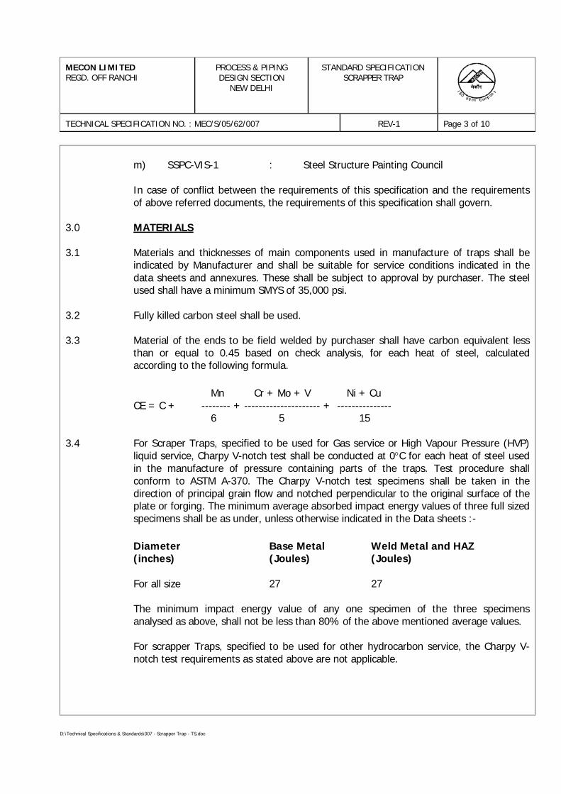
MECON LIMITEDREGD. OFF RANCHI
PROCESS & PIPINGDESIGN SECTION
NEW DELHI
STANDARD SPECIFICATIONSCRAPPER TRAP
TECHNICAL SPECIFICATION NO. : MEC/S/05/62/007 REV-1 Page 3 of 10
D:\Technical Specifications & Standards\007 - Scrapper Trap - TS.doc
m) SSPC-VIS-1 : Steel Structure Painting Council
In case of conflict between the requirements of this specification and the requirementsof above referred documents, the requirements of this specification shall govern.
3.0 MATERIALS
3.1 Materials and thicknesses of main components used in manufacture of traps shall beindicated by Manufacturer and shall be suitable for service conditions indicated in thedata sheets and annexures. These shall be subject to approval by purchaser. The steelused shall have a minimum SMYS of 35,000 psi.
3.2 Fully killed carbon steel shall be used.
3.3 Material of the ends to be field welded by purchaser shall have carbon equivalent lessthan or equal to 0.45 based on check analysis, for each heat of steel, calculatedaccording to the following formula.
Mn Cr + Mo + V Ni + CuCE = C + -------- + --------------------- + ---------------
6 5 15
3.4 For Scraper Traps, specified to be used for Gas service or High Vapour Pressure (HVP)liquid service, Charpy V-notch test shall be conducted at 0°C for each heat of steel usedin the manufacture of pressure containing parts of the traps. Test procedure shallconform to ASTM A-370. The Charpy V-notch test specimens shall be taken in thedirection of principal grain flow and notched perpendicular to the original surface of theplate or forging. The minimum average absorbed impact energy values of three full sizedspecimens shall be as under, unless otherwise indicated in the Data sheets :-
Diameter Base Metal Weld Metal and HAZ(inches) (Joules) (Joules)
For all size 27 27
The minimum impact energy value of any one specimen of the three specimensanalysed as above, shall not be less than 80% of the above mentioned average values.
For scrapper Traps, specified to be used for other hydrocarbon service, the Charpy V-notch test requirements as stated above are not applicable.
MECON LIMITEDREGD. OFF RANCHI
PROCESS & PIPINGDESIGN SECTION
NEW DELHI
STANDARD SPECIFICATIONSCRAPPER TRAP
TECHNICAL SPECIFICATION NO. : MEC/S/05/62/007 REV-1 Page 4 of 10
D:\Technical Specifications & Standards\007 - Scrapper Trap - TS.doc
3.5 For Scraper Traps, specified to be used for Gas service or High Vapour Pressure (HVP)liquid service, hardness test shall be carried out as per ASTM A370 for each heat of steelused. A full thickness cross section shall be taken for this purpose and the maximumhardness of the base material, weld metal and heat affected zone (HAZ) of all thepressure containing parts shall not exceed 248 HV10. The maximum difference inhardness of Base metal, Weld metal and Heat affected zone (HAZ) of pressurecontaining parts of the traps shall be less than 80 points Vicker’s HV10.
For scrapper Traps, specified to be used for other hydrocarbon service, the hardness testrequirements as stated above are not applicable.
4.0 DESIGN AND CONSTRUCTION
4.1 The cylindrical portion of the trap shall be designed as per design code and design factorindicated in the data sheets. Quick end closure shall be designed as per sec. ASME Sec.VIII, Div. 1 for design conditions indicated in data sheets. A corrosion allowance of 3mm shall be considered in design of the traps. Quality of welding shall be such that weldefficiency factor of 1.0 is achieved.
4.2 The trap shall be capable of handling instrumented pigs, model like Linalog 360 of AMFTuboscope or British gas magnetic inspection vehicle or equivalent and scraper pigs asspecified in scraper Trap data sheet.
4.3 The trap body and neck, diameter has been indicated in the data sheet. Trap length tosuit the purpose and thickness to meet the class rating shall be suggested by themanufacturer and approved by the purchaser. Circumferential weld on scraper tarpbody and neck shall not be permitted.
4.4 Concentric or eccentric reducer, as indicated in data sheets, used in the manufacture oftraps shall conform to MSS-SP-75.
4.5 Vents and drains shall be provided on each trap. The trap shall be provided with asuitable slope and the drain location shall be such that complete drainage of the trap ispossible. Sizes for vent and drain shall be as indicated in data sheet.
4.6 All branch connections shall be made by weldolets/ nippolet or by extrusions as indicatedin the data sheet. All weldolets shall confirm to MSS-SP-97 and nippolets shall bemanufacturer’s standard. The extruded opening shall be adequately heat treated andstress relieved.
4.7 End connections of traps shall be flanged or butt welded as indicated in data sheet.a) Flanged ends, if specified shall have dimension as per ASME B16.5 for sizes upto
24" NB (excluding 22 NB) and as per ASME B16.47 / MSS-SP-44 for sizes 22 NBand 26 NB and above. Flanges shall be as indicated in data sheets.
MECON LIMITEDREGD. OFF RANCHI
PROCESS & PIPINGDESIGN SECTION
NEW DELHI
STANDARD SPECIFICATIONSCRAPPER TRAP
TECHNICAL SPECIFICATION NO. : MEC/S/05/62/007 REV-1 Page 5 of 10
D:\Technical Specifications & Standards\007 - Scrapper Trap - TS.doc
b) Butt weld ends if specified shall have ends prepared as per ASME B16.25.However, end preparation for butt welding ends having unequal thicknesses withrespect, to connecting pipe shall be as per ASME B31.4/ ASME B31.8 asapplicable.
c) The location & orientation of all nozzle connections shall be submitted forpurchaser's approval before manufacturing.
4.8 The quick opening end closure shall be of clamp ring or band lock type or equivalentdesign. The closure shall also consist of a safety relief system allowing the opening onlywhen there is no pressure in the trap. Screwed type or plug-in type of end closures arenot acceptable. End closure shall be hand operated and operable by one operator. Endclosures of size 24" and above shall be fitted with worm gear operator for the opening ofthe closure.
Hinge of the closure shall be so designed that the weight of the end closure is fullysupported with out sagging.
4.9 Receiving traps shall be provided with a pig indicator in the middle of the neck and theindicator shall conform to the specification issued for the purpose. Pig indicator shall besuitable for bi-directional operation and shall have visual flag and manual reset. Thesame shall also have provision for remote indication. REFER SPECIFICATION No.MEC/S/05/62/48 and Pig Signaller Data Sheet.
4.10 Suitable handling system for inserting and retracting the scraper and instrumented pigsfrom the trap shall be provided with each trap. Handling system shall consist of afabricated structural steel framework comprising a bench fitted with a purpose-designedcradle for the pig. A pusher/ puller mechanism operated by a cable system employing ahand cranked winch shall be mounted on the bench framework for inserting/ retractingthe pig from the trap. The bench frame should be suitable for bolting to the floor. Allparts of the handling system in contact with each other shall be of the anti spark type.
4.11 Fabricated steel supports, minimum two numbers at suitable spacing shall be providedwith traps for mounting on concrete blocks. These supports will not be subjected topipeline achorage forces. The material of support shall be compatible with trap materialfor welding purposes. All welds shall be examined by magnetic particle method.
4.12 Completed assembly shall be stress relieved as per the provisions of the design codes.
4.13 All welds shall be made by welders and welding procedures qualified in accordance withthe provisions of ASME Sec. IX. The procedure qualification shall include impact test andhardness test when required as per clause 3.4 & 3.5 of this specification and shall meetthe requirements as specified therein.
MECON LIMITEDREGD. OFF RANCHI
PROCESS & PIPINGDESIGN SECTION
NEW DELHI
STANDARD SPECIFICATIONSCRAPPER TRAP
TECHNICAL SPECIFICATION NO. : MEC/S/05/62/007 REV-1 Page 6 of 10
D:\Technical Specifications & Standards\007 - Scrapper Trap - TS.doc
4.14 Repair by welding on parent metal is not allowed. Repair of welds shall be carried outonly after specific approval by purchaser's representative for each repair. The repairwelding shall be carried out by the welders and welding procedures duly qualified as perASME Section IX and records for each repair shall be maintained. The repair weldingprocedure qualification shall include impact test and hardness test when required as perclause 3.4 & 3.5 of this specification and shall meet the requirements as specifiedtherein.
4.15 The traps shall be equipped with a half internal removable filtering basket consisting of apunched plate with a least five rows of drain holes.
4.16 The filtering basket shall slide on guides on wheels and in all cases the material of theparts being in contact with each other shall be of the anti spark type.
4.17 The tolerance on internal diameter and out of roundness at the ends for the weldingend of the neck (at the end where connecting pipeline will be welded) shall be as perapplicable connected pipe specification as indicated in the data sheet.
5.0 INSPECTION AND TESTS
5.1 The manufacturer shall perform all inspections and test as per the requirements of thisspecification and the relevant codes prior to shipment at his works. Such inspections andtests shall be, but not limited to the following :-
5.1.1 All trap shall be visually inspected.
5.1.2 Chemical composition and mechanical properties including hardness shall be checked foreach heat of steel used.
5.1.3 Dimensional check shall be carried out as per the approved drawings.
5.1.4 Hydrostatic test shall be conducted for all scraper traps complete in all respects includingmounting of pig indicators at a pressure equal to 1.5 times the design pressure. The testpressure shall be held for a minimum period of one hour.
5.1.5 All butt welds shall be 100% radiographically inspected. Procedure and acceptancecriteria shall be as per API 1104.
5.1.6 Ultrasonic or magnetic particle inspection shall be carried out on all welds which inPurchaser's Representative's opinion can not be radiographically inspected. Procedureand acceptance criteria shall be as per ASME Sec. VIII, Appendix-U and VI respectively.
MECON LIMITEDREGD. OFF RANCHI
PROCESS & PIPINGDESIGN SECTION
NEW DELHI
STANDARD SPECIFICATIONSCRAPPER TRAP
TECHNICAL SPECIFICATION NO. : MEC/S/05/62/007 REV-1 Page 7 of 10
D:\Technical Specifications & Standards\007 - Scrapper Trap - TS.doc
5.1.7 All finished wrought weld shall be 100% ultrasonically inspected for lamination typedefects for a distance of 50mm from the end. Any lamination larger than 6.35 mm shallnot be acceptable.
5.1.8 All forgings shall be wet magnetic particle examined on 100% of the forged surfaces.Method and acceptance shall comply with MSS-SP-53.
5.1.9 A minimum of two closing and opening cycles shall be performed and correct operationof both quick opening closure and safety system shall be ascertained.
5.2 Purchaser's Representative reserves the right to perform stage wise inspection andwitness tests including hydrostatic test, as indicated in specification at manufacturer’sworks prior to shipment. Manufacturer shall give reasonable notice of time & shallprovide without charge reasonable access and facilities required for inspection, to thepurchaser's representative.
Inspection and tests performed / witnessed by Purchaser's Representative shall in noway relieve the Manufacturer's obligation of specific integrity of the scraper traps.
Manufacturer's equipment shall be subject to examination and approval by purchaser toensure proper fabrication and testing of traps.
6.0 TEST CERTIFICATES
Manufacturer shall furnish the following certificates
a) Test certificates relevant to the chemical and Mechanical properties includingHardness of the materials used for manufacture of trap as per relevant standardsand this specification.
b) Hydrostatic test certificates.
c) Test reports on radiography, ultrasonic inspection and magnetic particleexamination.
d) Test reports on heat treatment carried out, if any.
The certificate shall be considered valid only when signed by purchaser’s representative.
MECON LIMITEDREGD. OFF RANCHI
PROCESS & PIPINGDESIGN SECTION
NEW DELHI
STANDARD SPECIFICATIONSCRAPPER TRAP
TECHNICAL SPECIFICATION NO. : MEC/S/05/62/007 REV-1 Page 8 of 10
D:\Technical Specifications & Standards\007 - Scrapper Trap - TS.doc
7.0 PAINTING, MARKING AND SHIPMENT
7.1 After all inspection and test required have been carried out, all external surfaces shall bethoroughly cleaned to remove grease, dust and rust. Surface preparation shall be carriedout by shot blasting to SP-6 in accordance with "Steel Structures Painting Council VisualStandard - SSPC-VIS-1". Machined parts shall be coated with anti-rust removable paintand non machined parts shall be applied with two coats of protective paint.Manufactures shall indicate the type of paint used in the drawings submitted forapproval.
7.2 Marking shall be done on a stainless steel plate and affixed to the body by means ofcorrosion resistant fasteners. Marking shall include the following :-
a) Manufacturer's Nameb) Trap/ Neck Diameter, Thicknessc) Materiald) ASME Class Ratinge) Tag Numberf) Design Pressureg) Design Temperatureh) Test Pressurei) Design Factorj) Year of Manufacturek) Empty weight of the trap assembly.
7.3 Before shipment, traps shall be properly packed against damage duringtransportation. All machined surface subject to corrosion during transit shall be wellprotected by coat of grease or other suitable material. All traps shall be provided withsuitable protectors, for flange faces, securely attached to the traps. Bevel ends shallbe protected with metallic or high impact plastic bevel protectors.
7.4 Only those traps, which have been inspected and certified by the purchaser’sinspector shall be supplied.
8.0 GUARANTEE
8.1 Manufacturer shall guarantee that the trap alongwith accessories is in compliance withthe requirements of this specification for materials and workmanship. Manufacturer shallreplace or repair all parts which should result defective due to inadequate design or theworkmanship. In case the defect can not be eliminated, Manufacturer shall replace thetrap without any delay. Any defect occurring within the time period specified elsewhereshall be repaired making all necessary modifications and repair of defective parts free ofcharge to the purchaser.
MECON LIMITEDREGD. OFF RANCHI
PROCESS & PIPINGDESIGN SECTION
NEW DELHI
STANDARD SPECIFICATIONSCRAPPER TRAP
TECHNICAL SPECIFICATION NO. : MEC/S/05/62/007 REV-1 Page 9 of 10
D:\Technical Specifications & Standards\007 - Scrapper Trap - TS.doc
9.0 SPARES
9.1 Manufacturer shall furnish list of recommended spares and accessories for ScrapperTraps required during start up and commissioning. As a minimum, the commissioningspares shall include 200% extra consumable spares viz. gaskets/ o-rings/ seals etc. foreach trap. Cost of such spares shall be included by the Manufacturer in the item ratesindicated in Purchase Requisition.
9.2 Manufacturer shall furnish separately a list of recommended spares and accessoriesrequired for two years of normal operation and maintenance of Scraper Traps.
10.0 DOCUMENTATION
10.1 Manufacturer shall furnish at the time of bidding, the following documents:-
a) General arrangement drawing of scraper trap, pig signallers, quick opening endclosure with overall dimensions.
b) Clause wise list of deviations from this specification, if any listed at one place inthe document.
c) Reference list of similar supplies for the past five years including project, clientyear of supply & contact person.
d) Quality Assurance Plan (QAP) enclosed with this tender duly signed, stampedand accepted.
10.2 Within two weeks of placement of order, the manufacturer shall submit four copies of,but not limited to, the following drawings, documents and specifications for approval.
a) Calculations according to the relevant codes for the body including branchconnections and quick end closures.
b) Trap assembly and sectional drawings showing all parts with materials anddimensions.
c) Support Assembly Drawing.
d) Arrangement & details of foundation bolts for pig handling and lifting system,where applicable.
e) Welding procedure and method of manufacture.
MECON LIMITEDREGD. OFF RANCHI
PROCESS & PIPINGDESIGN SECTION
NEW DELHI
STANDARD SPECIFICATIONSCRAPPER TRAP
TECHNICAL SPECIFICATION NO. : MEC/S/05/62/007 REV-1 Page 10 of 10
D:\Technical Specifications & Standards\007 - Scrapper Trap - TS.doc
Once the above said documents have been approved by the Purchaser, any changes indesign, material and method of manufacturer shall be notified to the Purchaser, whoseapproval in writing of all changes shall be obtained before the traps are manufactured.
10.3 Within four weeks from the approval date Manufacturer shall submit one reproducibleand six copies of all approved drawings, documents and specification as listed in clause10.2 of this specification.
10.4 Prior to shipment, the manufacturer shall submit one reproducible and six copies of thefollowing :
a) Test certificate as listed in clause 6.0 of this specification.
b) Manual for installation, erection instructions, maintenance and operationsinstruction.
10.5 All documents shall be in English Language.
D:\old data\FATEH\MP Region\Kailaras\Tender RFQ\Plug Valves\Plug Valves - 003 - TS-R2.doc
PROCESS & PIPING DESIGN SECTIONMECON LIMITED
DELHI - 110 092
TECHNICAL SPECIFICATIONFOR
PLUG VALVES(NB ≥ 2”)
SPECIFICATION NO.: MEC/TS/05/62/003, Rev-2
MECON LIMITEDDelhi
PROCESS & PIPINGDESIGN SECTION
TECHNICAL SPECIFICATIONFOR
PLUG VALVES
TECHNICAL SPECIFICATION NO. : MEC/TS/05/62/003 REV-2 Page 1 of 13
D:\old data\FATEH\MP Region\Kailaras\Tender RFQ\Plug Valves\Plug Valves - 003 - TS-R2.doc
C O N T E N T S
Sl.No. Description Page No.
1.0 SCOPE 2
2.0 REFERENCE DOCUMENTS 2
3.0 MATERIALS & TEST PROCEDURES 3
4.0 DESIGN & CONSTRUCTION 4
5.0 INSPECTION & TESTS 7
6.0 EXTENT OF INSPECTION & TESTING 9
7.0 TEST CERTIFICATES 9
8.0 PAINTING, MARKING & SHIPMENT 10
9.0 SPARES & ACCESSORIES 10
10.0 DOCUMENTATION 11
11.0 GUARANTEE 12
PREPARED BY :
Gurdeep Singh
Date
CHECKED BY :
A.K. Sarkar
Date
APPROVED BY :
A.K. Johri
Date
MECON LIMITEDDelhi
PROCESS & PIPINGDESIGN SECTION
TECHNICAL SPECIFICATIONFOR
PLUG VALVES
TECHNICAL SPECIFICATION NO. : MEC/TS/05/62/003 REV-2 Page 2 of 13
D:\old data\FATEH\MP Region\Kailaras\Tender RFQ\Plug Valves\Plug Valves - 003 - TS-R2.doc
1.0 SCOPE
This specification covers the minimum requirements for design, manufacture and supplyof carbon steel plug valves of size DN 50mm (2") and above and ANSI Class 150# thru900# for use in onshore pipeline systems handling non sour hydrocarbons in liquidphase or gaseous phase including Liquefied Petroleum Gas (LPG).
2.0 REFERENCE DOCUMENTS
2.1 All valves shall be manufactured and supplied in accordance with the Twenty SecondEdition, January, 2002, or the latest edition of American Petroleum Institute (API)Specification 6D, twenty first edition, 1994 including supplement 1 & 2 thereof withadditions and modifications as indicated in the following sections of this specification.
2.2 Reference has also been made in this specification to the latest edition of the followingCodes, Standards and Specifications :
ASME B 16.5 : Pipe flanges and flanged fittings
ASME B 16.25 : Buttwelding ends
ASME B 16.34 : Valves – Flanged, threaded and welding end
ASME B16.47 : Large diameter steel flanges
ASME B 31.3 : Chemical & process plant piping system
ASME B 31.4 : Liquid transportation systems for hydrocarbons andother liquids
ASME B 31.8 : Gas transmission and distribution piping systems
ASME Sec.VIII : Boiler and pressure vessel code
ASTM A 370 : Standard test methods and definitions for mechanicaltesting of steel products
ASTM B 733 : Autocatalytic nickel phosphorous coating on metals
API 6FA : Fire test for valves
API 1104 : Welding of pipelines and related facilities
BS:6755 (Part-II) : Testing of valves – Specification for fire type - testingrequirements
MSS-SP-6 : Standard finishes for contact faces of pipe flanges andconnecting-end flanges of valves and fittings
MECON LIMITEDDelhi
PROCESS & PIPINGDESIGN SECTION
TECHNICAL SPECIFICATIONFOR
PLUG VALVES
TECHNICAL SPECIFICATION NO. : MEC/TS/05/62/003 REV-2 Page 3 of 13
D:\old data\FATEH\MP Region\Kailaras\Tender RFQ\Plug Valves\Plug Valves - 003 - TS-R2.doc
MSS-SP-44 : Steel pipeline flanges
SSPC-VIS-1 : Steel structures painting council-visual standard
2.3 In case of conflict between the requirements of this specification, API 6D and theCodes, Standards and Specifications referred in clause 2.2 above, the requirements ofthis specification shall govern. Order of precedence shall be as follows :
• Data Sheets• This Specification• API 6D Specification• Other Referred Codes & Standards• Manufacturer’s Standard
3.0 MATERIALS & TEST PROCEDURES
3.1 Material for major components of the valves shall be as indicated in Valve Data Sheet.Other components shall be as per Manufacturer's standard which will be subject toapproval by Purchaser.
3.2 Carbon steel used for the manufacture of valves shall be fully killed.
3.3 Chemical composition (check analysis) of valve end connection which are subject tofurther welding by Purchaser shall meet the following requirements for each heat ofsteel used:a) Carbon : 0.22% (max.)b) Manganese : 1.70 % (max.)c) Silicon : 0.55 % (max.)d) Phosphorus : 0.030 % (max.)e) Sulphur : 0.030 % (max.)
Total percentage of Vanadium, Niobium and Titanium shall not exceed 0.20. Residualelements shall not exceed the following limits :a) Nitrogen : 0.019 %b) Nickel : 0.30 %c) Copper : 0.20 %d) Aluminum : 0.070 %e) Chromium : 0.15 %f) Molybdenum : 0.05 %
Carbon equivalent (CE) as calculated by the following shall not exceed 0.45%.
Mn Cr + Mo + V Ni + CuCE = C + -------- + ---------------------- + ---------------
6 5 15
MECON LIMITEDDelhi
PROCESS & PIPINGDESIGN SECTION
TECHNICAL SPECIFICATIONFOR
PLUG VALVES
TECHNICAL SPECIFICATION NO. : MEC/TS/05/62/003 REV-2 Page 4 of 13
D:\old data\FATEH\MP Region\Kailaras\Tender RFQ\Plug Valves\Plug Valves - 003 - TS-R2.doc
3.4 For valves specified for Gas Service or high vapour pressure liquid service, charpy V-Notch test on each heat of base material shall be conducted as per API 6D, for allpressure containing parts such as body, end flanges and welding ends as well as thebolting material for pressure containing parts. Unless specified otherwise in Valve DataSheets, the Charpy impact test shall be conducted at 0°C. The Charpy impact testspecimen shall be taken in the direction of principal grain flow and notchedperpendicular to the original surface of plate or forging.
Unless specified otherwise in Valve Data Sheets, the minimum average absorbedenergy per set of three specimens shall be 27 J with an individual minimum perspecimen of 22 J.
3.5 For valves specified for Gas Service or high vapour pressure liquid service, the hardnessof base material of body and principal parts of the valve such as plug, stem, etc., shallnot exceed 22 RC.
3.6 Plug for valve size DN 200mm (8”) and above or as specified in Valve Data Sheets shallhave Electroless Nickel Plating (ENP) or equivalent. The hardness of plating shall beminimum 50 RC. Manufacturer shall ensure that the adhesive strength of plating issufficient so as to prevent peeling of plating during operation of the valve.
3.7 All process-wetted parts, metallic and non-metallic, shall be suitable for the fluids andservice specified by the Purchaser. The service gas composition when applicable shallbe as given in Annexure-I.
4.0 DESIGN & CONSTRUCTION
4.1 The Manufacturer shall have a valid license to use API 6D monogram for manufactureof Plug Valves.
4.2 Valve pattern shall be short, regular or venturi as specified in the following table:
Class Size Range, NB mm (inch) Pattern50-100 (2-4) Short
150 150-300 (6-12) Regular350 (14) & above Venturi50-100 (2-4) Short
300 150-250 (6-10) Regular300 (12) & above Venturi50-250 (2-10) Regular
600 300 (12) & above Venturi50-250 (2-10) Regular
900 300 (12) & above Venturi
MECON LIMITEDDelhi
PROCESS & PIPINGDESIGN SECTION
TECHNICAL SPECIFICATIONFOR
PLUG VALVES
TECHNICAL SPECIFICATION NO. : MEC/TS/05/62/003 REV-2 Page 5 of 13
D:\old data\FATEH\MP Region\Kailaras\Tender RFQ\Plug Valves\Plug Valves - 003 - TS-R2.doc
4.3 Valve shall have an inherent feature using line pressure to ensure that the line pressurecannot cause taper locking of the plug/ plug movement into taper i.e. valves shall be ofpressure balanced design.
4.4 Cover shall be bolted to the body and screwed connections are not acceptable.
4.5 Soft seats to achieve a seal between plug and body are not permitted.
4.6 All valves shall have provisions for secondary sealant injection under full line pressurefor seat and stem seals. Sealant injection points shall be provided with a ball type checkvalve or needle valve to replace the sealant injection fitting under full line pressure.
4.7 Valves shall have vent and drain connections as per API 6D.
4.8 When specified in the Valve Data Sheet, valves shall be designed to withstand asustained internal vacuum of at least one milli-bar in both open and closed position.
4.9 Valve design shall ensure repair of gland packing under full line pressure.
4.10 a) Valve ends shall be either flanged or butt welded or one end flanged and one end buttwelded as indicated in Valve Data Sheet. Flanges of the flanged end cast/ forged bodyvalves shall be integrally cast/forged with the body of valve. Face-to-face/ end-to-enddimensions shall conform to API 6D.
b) Flanged end shall have dimensions as per ASME B16.5 for valve sizes upto DN 600mm(24 inches) excluding DN 550mm (22 inches) and as per MSS-SP-44 for valve sizes DN550mm (22 inches) & for DN 650mm (26 inches) and above. Flange face shall be eitherraised face or ring joint type as indicated in Valve Data Sheet. Flange face finish shall beserrated or smooth as indicated in Valve Data Sheet. Smooth finish when specified shallbe 125 to 200 AARH. In case of RTJ flanges, the groove hardness shall be minimum140 BHN.
c) Butt weld end preparation shall be as per ASME B16.25. The thickness of the pipe towhich the valve has to be welded shall be as indicated in Valve Data Sheet. Valvesshall be without transition pups. In case significant difference exists betweenthickness of welding ends of valve and connecting pipe, the welding ends of valveshall have bevel preparation as per ASME B31.4 or ASME B31.8, as applicable.
4.11 Valves shall be provided with position indicator and stops at the fully open and fullyclosed positions.
4.12 Valves of size DN 200mm (8”) and above shall be equipped with lifting lugs. Tappedholes and eye bolts shall not be used for lifting lugs.
4.13 Valves shall have locking devices to be locked either in full open or full close positionwhen indicated in the Valve Data Sheets. Locking devices shall be permanently attachedto the valve operator and shall not interfere with operation of the valve.
MECON LIMITEDDelhi
PROCESS & PIPINGDESIGN SECTION
TECHNICAL SPECIFICATIONFOR
PLUG VALVES
TECHNICAL SPECIFICATION NO. : MEC/TS/05/62/003 REV-2 Page 6 of 13
D:\old data\FATEH\MP Region\Kailaras\Tender RFQ\Plug Valves\Plug Valves - 003 - TS-R2.doc
4.14 Valves shall be of fire safe design as per BS:6755 (Part-II)/ API 6FA, if indicated inValve Data Sheet.
4.15 Valves shall be suitable for either buried or above ground installation as indicated in theValve Data Sheet.
4.16 Valves with stem extension, when indicated in Valve Data Sheet shall have followingprovisions :
a) Valves provided with stem extension shall have water proof outer casing. Lengthof stem extension shall be as indicated in the Valve Data Sheet. The lengthindicated corresponds to the distance between the centreline of the valveopening and the top of the mounting flange for valve operating device (gearoperator/ power actuator as applicable).
b) Vent and drain connections shall be terminated adjacent to the valve operatorby means of suitable piping anchored to the valve body. Pipe used shall be API5L Gr. B/ ASTM A106 Gr. B, with Sch. 160. Fittings shall be ASTM A105/ ASTMA 234 Gr. WPB, Socket Welded, ANSI class 6000.
c) Sealant injection lines shall be extended and terminated adjacent to the valveoperator in manner as indicated in (b) above.
d) Stem extension and stem housing design shall be such that the completeassembly will form a rigid unit giving a positive drive under all conditions with nopossibility of free movements between valve body stem extension or itsoperator.
e) Outer casing of stem extension shall have 3/8" or ½" NPT plugs at the top andbottom, for draining and filling with oil to prevent internal corrosion.
4.17 Operating Devices
a) Valves shall have a power actuator or manual operator as indicated in the Valve Data Sheet. Manual operated valves of size < DN 100mm (4”) shall bewrench operated and valves of sizes > DN 150mm (6") shall be gear operated.Each wrench operated valve shall be supplied with wrench. Valve design shall besuch that damage due to malfunctioning of the operator or its controls will onlyoccur in the operator gear train or power cylinder and damaged parts can bereplaced without the bonnet being removed.
b) The power actuator shall be in accordance with the specification issued for thepurpose and as indicated in the valve and actuator data sheet. Operating timeshall be as indicated in valve data sheet. Valve operating time shall correspondto full close to full open / full open to full close under maximum differentialpressure corresponding to the valve rating. For actuated valves, the actuatortorque shall be atleast 1.25 times the maximum torque required to operate thevalve under maximum differential pressure corresponding to the valve classrating.
c) Operating device shall be designed for easy operation of valve under maximumdifferential pressure corresponding to the valve rating.
MECON LIMITEDDelhi
PROCESS & PIPINGDESIGN SECTION
TECHNICAL SPECIFICATIONFOR
PLUG VALVES
TECHNICAL SPECIFICATION NO. : MEC/TS/05/62/003 REV-2 Page 7 of 13
D:\old data\FATEH\MP Region\Kailaras\Tender RFQ\Plug Valves\Plug Valves - 003 - TS-R2.doc
d) For manual operation of all valves, the diameter of the hand wheel or the lengthof operating lever shall be such that under the maximum differential pressure,the total force required to operate the valve does not exceed 350 N.Manufacturer shall also indicate the number of turns of hand wheel (in case ofgear operator), required to operate the valve from full open to full closeposition.
e) Direction of operation of hand wheel or wrench shall be in clock-wise directionwhile closing the valve. Hand wheels shall not have protruding spokes.
f) Gear operators, if specified, shall have a self locking provision and shall be fullyencased in waterproof/ dustproof/ weatherproof/ splashproof enclosure andshall be filled with suitable grease.
4.18 Repair by welding is not permitted for fabricated and forged body valves. Howeverrepair by welding as per ASME B16.34 is permitted for cast body valves. Repair shall becarried out before any heat treatment of casting is done. Repair welding procedurequalification shall also include impact test and hardness test when required as perClause 3.4 and 3.6 of this specification and shall meet the requirements as specifiedtherein.
4.19 The tolerance on internal diameter and out of roundness at the ends for welded endsvalves shall be as per connected pipe specification as indicated in the Valve Data Sheet.
4.20 Valve stem shall be capable of withstanding the maximum operating torque required tooperate the valve against the maximum differential pressure corresponding toapplicable class rating. The combined stress shall not exceed the maximum allowablestresses specified in ASME section VIII, Division-1.
For Power Actuated Valves, the valve stem shall be designed for maximum outputtorque of the selected power actuator (including gear box, if any) at the valves stem.
5.0 INSPECTION & TESTS
5.1 The Manufacturer shall perform all inspection and tests as per the requirements of thisspecification and the relevant codes, prior to shipment at his works. Such inspectionand tests shall be, but not limited to, the following :
5.1.1 All valves shall be visually inspected.
5.1.2 Dimensional check shall be carried out as per the Purchaser approved drawings.
5.1.3 Chemical composition and mechanical properties shall be checked as per relevantmaterial standards and this specification, for each heat of steel used.
5.1.4 a) Non-destructive examination of individual valve material and component consisting of but not limited to castings, forgings, plates and assembly weldsshall be carried out by the Manufacturer.
MECON LIMITEDDelhi
PROCESS & PIPINGDESIGN SECTION
TECHNICAL SPECIFICATIONFOR
PLUG VALVES
TECHNICAL SPECIFICATION NO. : MEC/TS/05/62/003 REV-2 Page 8 of 13
D:\old data\FATEH\MP Region\Kailaras\Tender RFQ\Plug Valves\Plug Valves - 003 - TS-R2.doc
b) Valves castings shall be radiographically examined at the cover and bodyportion, seat location, flanged body ends and circumference of ends to be fieldwelded. Procedure and acceptance criteria shall be as per ASME B16.34. Theextent of radiography shall be as follows :
ANSI Class 150 - All Sizes - Nil
ANSI Class 300 - ≤ DN 400mm (16") - Nil≥ DN 450mm (18") - 100%
ANSI Class 600 - All Sizes - 100%and above
All castings shall be wet magnetic particle inspected 100 % of the internalsurfaces. Method and acceptance shall comply with ASME B16.34.
c) Valve forgings shall be examined by ultrasonic method. Inspection procedureand acceptance criteria shall be as per Annexure E of ASME B16.34.
5.1.5 Areas which, in Purchaser's Inspector’s opinion, cannot be inspected by radiographicmethods shall be checked by ultrasonic or magnetic particle methods and acceptancecriteria shall be as per ASME Sec-VIII, Division I, Appendix 12 and Appendix 6respectively.
5.1.6 a) Weld ends of all cast valves shall be 100% radiographically examined andacceptance criteria shall be as per ASME B16.34.
b) After final machining all bevel surfaces shall be inspected by dye penetrant, orwet magnetic particle methods. Any defects longer than 6.35mm shall berejected and also defects between 6.35mm and 1.59mm that are separated by adistance less than 50 times their greatest length. Weld repair of bevel surface isnot permitted. Rejectable defects must be removed.
c) All finished wrought weld ends subject to welding in the field shall be 100%ultrasonically tested for lamination type defects for a distance of 50mm from theend. Laminations shall not be acceptable.
5.1.7 All valves shall be tested in compliance with the requirements of API 6D. Hydrostaticshell testing shall ensure that the whole of the shell is subjected to the test pressure. Ifnecessary, the empty shell shall be pressure tested prior to assembly of the plug. Thedrain, vent and sealant lines shall be either included in the hydrostatic shell test ortested independently. No leakage is permissible during hydrostatic testing.
5.1.8 A supplementary air seat test as per API 6D shall be carried out for all valves. Noleakage is allowed. Test pressure shall be held for at least 15 minutes.
MECON LIMITEDDelhi
PROCESS & PIPINGDESIGN SECTION
TECHNICAL SPECIFICATIONFOR
PLUG VALVES
TECHNICAL SPECIFICATION NO. : MEC/TS/05/62/003 REV-2 Page 9 of 13
D:\old data\FATEH\MP Region\Kailaras\Tender RFQ\Plug Valves\Plug Valves - 003 - TS-R2.doc
5.1.9 Manufacturer who intends bidding must submit at bid stage, certificate and report forsuccessful fire safe tests for all types of valves in accordance with BS:6755 (Part-II)/API 6FA, as applicable in Valve Data Sheet.
Failure to comply with the requirement shall be a cause of rejection of the offer.
5.1.10 Valve shall be subjected to Operational Torque Test as per supplementary testrequirement of API 6D under hydraulic pressure equal to the maximum differentialpressure corresponding to the valve rating. The maximum handwheel force shall notexceed 350 N.
5.1.11 Power actuated valves shall be tested after assembly at the valve Manufacturer's works.Actuator shall be capable to allow minimum five consecutive "opening" and "closing"cycles. To achieve this, the Manufacturer shall provide "closing" and "opening"operations. This test shall be conducted on one valve out of a lot of five valves of thesame size, rating and actuator type. In case the test result dose not meet therequirements, retesting/ rejection of the lot shall be as decided by Purchaser'sInspector.
The actuator shall be adjusted to ensure that opening and closing time is within thelimits stated in Actuator Data Sheet issued for the purpose.
The hand operator installed on the actuator shall also be checked after the cyclictesting, for satisfactory manual over-ride performance.
5.2 Purchaser reserves the right to perform stagewise inspection and witness tests asindicated in para 5.1 at Manufacturer's works prior to shipment. Manufacturer shall givereasonable access and facilities required for inspection to Purchaser's Inspector.
Purchaser reserves the right to request additional testing at any time to confirm orfurther investigate a suspected fault. If the suspected fault is confirmed, the costincurred shall be to Manufacturer's account.
In no case shall any action of Purchaser or his representative relieve the Manufacturerof his responsibility for material, design, quality or operation of valves.
Inspection and tests performed/ witnessed by the Purchaser's Inspector shall in no wayrelieve the Manufacturer's obligation to perform the required inspection and tests.
6.0 EXTENT OF INSPECTION & TESTING
6.1 Purchaser's Inspector shall perform inspection and witness test on all valves asindicated in the Quality Assurance Plan (QAP) attached with this specification.
6.2 The hydrostatic testing and cyclic opening and closing of the valves with the operatorshall be witnessed by Purchaser's Inspector.
MECON LIMITEDDelhi
PROCESS & PIPINGDESIGN SECTION
TECHNICAL SPECIFICATIONFOR
PLUG VALVES
TECHNICAL SPECIFICATION NO. : MEC/TS/05/62/003 REV-2 Page 10 of 13
D:\old data\FATEH\MP Region\Kailaras\Tender RFQ\Plug Valves\Plug Valves - 003 - TS-R2.doc
7.0 TEST CERTIFICATES
7.1 Manufacturer shall submit the following certificates :
a) Mill test certificates relevant to the chemical analysis and mechanical propertiesof the materials used for valve construction as per the relevant standards.
b) Test certificates on hydrostatic and pneumatic test complete with records oftiming and pressure of each test.
c) Test reports conforming to clause 5.1.9 of this specification, if applicable.
d) Test reports on radiographic and ultrasonic inspection.
e) Test reports on operation of valves conforming to clause 5.1.10 and 5.1.11 ofthis specification.
f) All other test reports and certificates as required by API 6D and thisspecification.
The certificates shall be valid only when signed by Purchaser's Inspector. Only thosevalves which have been certified by Purchaser’s Inspector shall be dispatched fromManufacturer's works.
8.0 PAINTING, MARKING & SHIPMENT
8.1 Valve surface shall be thoroughly cleaned, freed from rust and grease and applied withsufficient coats of corrosion resistant paint. Surface preparation shall be carried out byshot blasting to SP 6 in accordance with "Steel Structures Painting Council - VisualStandard - SSPC-VIS-1". For the valves to be installed underground, when indicated inValve Data Sheet, external surfaces of the buried portion of valves shall be painted withthree coats of suitable coal tar epoxy resin with a minimum dry film thickness of 300microns.
8.2 Manufacturer shall indicate the type of corrosion resistant paint used, in the drawingssubmitted for approval.
8.3 All valves shall be marked as per API 6D. The units of marking shall be metric exceptNominal Diameter which shall be in inches. Marking shall be done by die-stamping onthe bonnet or on the housing. However for buried valves the marking shall be done onthe above ground portion of the stem housing only.
8.4 Valve ends shall be suitably protected to avoid any damage during transit. All threadedand machined surfaces subject to corrosion shall be well protected by a coat of greaseor other suitable material. All valves shall be provided with suitable protectors, forflange faces, securely attached to the valves. Bevel ends shall be protected with metallicbevel protectors.
MECON LIMITEDDelhi
PROCESS & PIPINGDESIGN SECTION
TECHNICAL SPECIFICATIONFOR
PLUG VALVES
TECHNICAL SPECIFICATION NO. : MEC/TS/05/62/003 REV-2 Page 11 of 13
D:\old data\FATEH\MP Region\Kailaras\Tender RFQ\Plug Valves\Plug Valves - 003 - TS-R2.doc
8.5 All sealant lines and other cavities of the valves shall be filled with sealant beforeshipment.
8.6 Packaging and shipping instructions shall be as per API 6D.
8.7 Packages shall be marked legibly, with suitable marking ink, the following.
a) Order Numberb) Manufacturer's Namec) Valve Size and Ratingd) Tag Numbere) Serial Number
9.0 SPARES & ACCESSORIES
9.1 Manufacturer shall recommend and quote separately the spares for valves required forcommissioning and two years of normal operation. List of such spares without priceshall be indicated alongwith technical bid and separately with price.
9.2 Manufacturer shall recommend and quote unit price separately for the accessories (likewrench, sealant injector, etc.), sealant and special tools required for maintenance ofvalves.
10.0 DOCUMENTATION
10.1 At the time of bidding, the bidder shall submit the following documents :
a) General arrangement/ assembly drawings showing all features and relativepositions & sizes of vents, drains, gear box & other external parts together withoverall dimensions.
b) Sectional drawing showing major parts with reference numbers and materialspecification.
c) Reference list of similar plug valves manufactured and supplied in last five years,indicating all relevant details including project, year, client, location, size rating,service, etc.
d) Torque curves for the power actuated valves alongwith break torque andmaximum allowable stem torque. In addition, sizing criteria and torquecalculations shall also be submitted for power actuated valves.
e) Descriptive technical catalogues of the Manufacturer.
f) Copy of valid API 6D certificate, wherever applicable.
MECON LIMITEDDelhi
PROCESS & PIPINGDESIGN SECTION
TECHNICAL SPECIFICATIONFOR
PLUG VALVES
TECHNICAL SPECIFICATION NO. : MEC/TS/05/62/003 REV-2 Page 12 of 13
D:\old data\FATEH\MP Region\Kailaras\Tender RFQ\Plug Valves\Plug Valves - 003 - TS-R2.doc
g) Details of support foot, including dimensions and distance from valve centreline to bottom of support foot.
h) Quality Assurance Plan enclosed with this tender duly signed, stamped andaccepted.
IMPORTANTThe drawings to be submitted alongwith the bid shall be in total compliancewith the requirement of technical specification and data sheets of the valveswith no exception & deviation.
10.2 Within two weeks of placement of order, the manufacturer shall submit six copies of,but not limited to, the following drawings, documents and specifications for approval :
a) Design drawings and relevant calculations for pressure containing parts andother principle parts.
b) Detailed sectional arrangement drawing showing all parts with referencenumbers and materials specification.
c) Assembly drawings with overall dimensions & clearances required and showingall features. Drawing shall also indicate the numbers of turns of handwheel (incase of gear operator) required for operating the valve from full open to fullclose position and the painting scheme.
d) Welding, heat treatment, testing and quality control procedures.
e) Details of corrosion resistant paint to be applied on the valves.
f) Design calculation for pressure containing parts.
Manufacture of valves shall commence only after approval of the above documents.Once approval has been given by Purchaser, any change in design, material andmethod of manufacture shall be notified to the Purchaser, whose approval in writing forall changes shall be obtained before the valves are manufactured.
10.3 Within 30 days from the approval date, Manufacturer shall submit one reproducible andsix copies of the approved drawings, documents and specification as listed in clause10.2 of this specification.
10.4 Prior to shipment, Manufacturer shall submit one reproducible and six copies offollowing :-a) Test certificates as listed in clause 7.0 of this specification.b) Manual for installation, erection instructions, maintenance and operation
instructions, including a list of recommended spares for the valves.
10.5 All documents shall be in English Language.
MECON LIMITEDDelhi
PROCESS & PIPINGDESIGN SECTION
TECHNICAL SPECIFICATIONFOR
PLUG VALVES
TECHNICAL SPECIFICATION NO. : MEC/TS/05/62/003 REV-2 Page 13 of 13
D:\old data\FATEH\MP Region\Kailaras\Tender RFQ\Plug Valves\Plug Valves - 003 - TS-R2.doc
11.0 GUARANTEE
11.1 Manufacturer shall guarantee that the materials and machining of valves and fittingscomply with the requirements in this specification and in the Purchase Order.
11.2 Manufacturer is bound to replace or repair all valve parts which should result defectivedue to inadequate engineering or to the quality of materials and machining.
11.3 If valve defect or malfunctioning cannot be eliminated, Manufacturer shall replace thevalve without delay.
11.4 Any defect occurring during the period of Guarantee shall be attended to by making allnecessary modifications and repair of defective parts free of charge to the Purchaser asper the relevant clause of the bid document.
11.5 All expenses shall be to Manufacturer’s account.
D:\old data\FATEH\MP Region\Kailaras\Tender RFQ\Check Valve\Check Valves - 004 - TS-R2.doc
PROCESS & PIPING DESIGN SECTIONMECON LIMITEDDELHI – 110 092
TECHNICAL SPECIFICATIONFOR
CHECK VALVES
SPECIFICATION NO. : MEC/TS/05/62/004, Rev-2
MECON LIMITEDDelhi
PROCESS & PIPINGDESIGN SECTION
TECHNICAL SPECIFICATIONFOR
CHECK VALVES
TECHNICAL SPECIFICATION NO. : MEC/TS/05/62/004 REV-2 Page 1 of 8
D:\old data\FATEH\MP Region\Kailaras\Tender RFQ\Check Valve\Check Valves - 004 - TS-R2.doc
C O N T E N T S
Sl.No. Description Page No.
1.0 SCOPE 2
2.0 REFERENCE DOCUMENTS 2
3.0 MATERIALS 2
4.0 DESIGN AND CONSTRUCTION 3
5.0 INSPECTION AND TESTS 4
6.0 TEST CERTIFICATES 5
7.0 PAINTING, MARKING AND SHIPMENT 6
8.0 SPARES AND ACCESSORIES 6
9.0 DOCUMENTATION 6
10.0 GUARANTEE 7
PREPARED BY CHECKED BY APPROVED BY
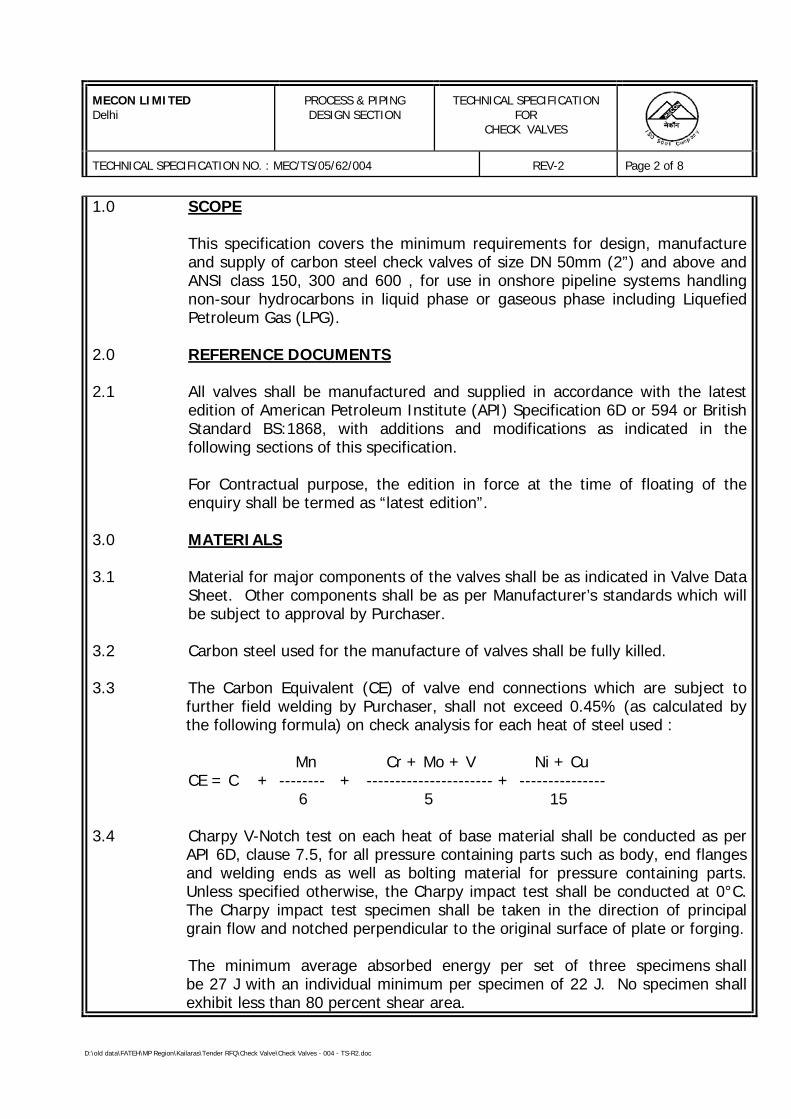
MECON LIMITEDDelhi
PROCESS & PIPINGDESIGN SECTION
TECHNICAL SPECIFICATIONFOR
CHECK VALVES
TECHNICAL SPECIFICATION NO. : MEC/TS/05/62/004 REV-2 Page 2 of 8
D:\old data\FATEH\MP Region\Kailaras\Tender RFQ\Check Valve\Check Valves - 004 - TS-R2.doc
1.0 SCOPE
This specification covers the minimum requirements for design, manufactureand supply of carbon steel check valves of size DN 50mm (2”) and above andANSI class 150, 300 and 600 , for use in onshore pipeline systems handlingnon-sour hydrocarbons in liquid phase or gaseous phase including LiquefiedPetroleum Gas (LPG).
2.0 REFERENCE DOCUMENTS
2.1 All valves shall be manufactured and supplied in accordance with the latestedition of American Petroleum Institute (API) Specification 6D or 594 or BritishStandard BS:1868, with additions and modifications as indicated in thefollowing sections of this specification.
For Contractual purpose, the edition in force at the time of floating of theenquiry shall be termed as “latest edition”.
3.0 MATERIALS
3.1 Material for major components of the valves shall be as indicated in Valve DataSheet. Other components shall be as per Manufacturer’s standards which willbe subject to approval by Purchaser.
3.2 Carbon steel used for the manufacture of valves shall be fully killed.
3.3 The Carbon Equivalent (CE) of valve end connections which are subject tofurther field welding by Purchaser, shall not exceed 0.45% (as calculated bythe following formula) on check analysis for each heat of steel used :
Mn Cr + Mo + V Ni + CuCE = C + -------- + ---------------------- + ---------------
6 5 15
3.4 Charpy V-Notch test on each heat of base material shall be conducted as perAPI 6D, clause 7.5, for all pressure containing parts such as body, end flangesand welding ends as well as bolting material for pressure containing parts.Unless specified otherwise, the Charpy impact test shall be conducted at 0°C.The Charpy impact test specimen shall be taken in the direction of principalgrain flow and notched perpendicular to the original surface of plate or forging.
The minimum average absorbed energy per set of three specimens shallbe 27 J with an individual minimum per specimen of 22 J. No specimen shallexhibit less than 80 percent shear area.
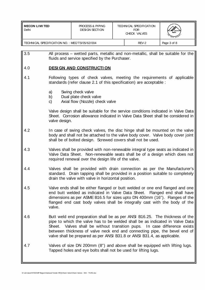
MECON LIMITEDDelhi
PROCESS & PIPINGDESIGN SECTION
TECHNICAL SPECIFICATIONFOR
CHECK VALVES
TECHNICAL SPECIFICATION NO. : MEC/TS/05/62/004 REV-2 Page 3 of 8
D:\old data\FATEH\MP Region\Kailaras\Tender RFQ\Check Valve\Check Valves - 004 - TS-R2.doc
3.5 All process – wetted parts, metallic and non-metallic, shall be suitable for thefluids and service specified by the Purchaser.
4.0 DESIGN AND CONSTRUCTION
4.1 Following types of check valves, meeting the requirements of applicablestandards (refer clause 2.1 of this specification) are acceptable :
a) Swing check valveb) Dual plate check valvec) Axial flow (Nozzle) check valve
Valve design shall be suitable for the service conditions indicated in Valve DataSheet. Corrosion allowance indicated in Valve Data Sheet shall be considered invalve design.
4.2 In case of swing check valves, the disc hinge shall be mounted on the valvebody and shall not be attached to the valve body cover. Valve body cover jointshall be of bolted design. Screwed covers shall not be used.
4.3 Valves shall be provided with non-renewable integral type seats as indicated inValve Data Sheet. Non-renewable seats shall be of a design which does notrequired renewal over the design life of the valve.
4.4 Valves shall be provided with drain connection as per the Manufacturer’sstandard. Drain tapping shall be provided in a position suitable to completelydrain the valve with valve in horizontal position.
4.5 Valve ends shall be either flanged or butt welded or one end flanged and oneend butt welded as indicated in Valve Data Sheet. Flanged end shall havedimensions as per ASME B16.5 for sizes upto DN 400mm (16”). Flanges of theflanged end cast body valves shall be integrally cast with the body of thevalve.
4.6 Butt weld end preparation shall be as per ANSI B16.25. The thickness of thepipe to which the valve has to be welded shall be as indicated in Valve DataSheet. Valves shall be without transition pups. In case difference existsbetween thickness of valve neck end and connecting pipe, the bevel end ofvalve shall be prepared as per ANSI B31.8 or ANSI B31.4, as applicable.
4.7 Valves of size DN 200mm (8”) and above shall be equipped with lifting lugs. Tapped holes and eye bolts shall not be used for lifting lugs.
MECON LIMITEDDelhi
PROCESS & PIPINGDESIGN SECTION
TECHNICAL SPECIFICATIONFOR
CHECK VALVES
TECHNICAL SPECIFICATION NO. : MEC/TS/05/62/004 REV-2 Page 4 of 8
D:\old data\FATEH\MP Region\Kailaras\Tender RFQ\Check Valve\Check Valves - 004 - TS-R2.doc
4.8 An arrow indicating the direction of flow shall be embossed or cast on the bodyof all valves.
4.9 All welds shall be made by welders and welding procedures qualified inaccordance with the provisions of ASME Section IX. The welding and repairwelding procedure qualification shall include impact test and shall meet therequirements of clause 3.4 of this specification.
4.10 Repair by welding is permitted for cast body valves subject to written approvalby Purchaser and shall be carried out as per ANSI B16.34. Repair shall becarried out before any heat treatment of casting is done.
5.0 INSPECTION AND TESTS
5.1 The Manufacturer shall perform all inspection and tests as per the requirementsof this specification and the relevant codes, prior to shipment at his works. Suchinspection and tests shall be, but not limited to, the following :
5.1.1 All valves shall be visually inspected.
5.1.2 Dimensional check on all valves shall be carried out as per the Purchaserapproved drawings.
5.1.3 Chemical compositions and mechanical properties shall be checked as perrelevant material standards and this specification, for each heat of steel used.
5.1.4 a) Where applicable, the body castings of valves shall be radiographicallyexamined on 100% of the surface of critical areas as per ANSI B16.34. Procedure and acceptance criteria shall be as per ANSI B16.34.
b) Where applicable, valve body made by forging and plate componentsshall be ultrasonically examined in accordance with procedure andacceptance standard of Annexure E of ANSI B16.34.
c) The extent of radiography/ ultrasonic examination shall be as follows :
ANSI class 150 - All sizes - Nil
ANSI class 300 - < DN 400mm (16”) - Nil> DN 450mm (18”) - 100%
ANSI class 600 - All sizes - 100%

MECON LIMITEDDelhi
PROCESS & PIPINGDESIGN SECTION
TECHNICAL SPECIFICATIONFOR
CHECK VALVES
TECHNICAL SPECIFICATION NO. : MEC/TS/05/62/004 REV-2 Page 5 of 8
D:\old data\FATEH\MP Region\Kailaras\Tender RFQ\Check Valve\Check Valves - 004 - TS-R2.doc
5.1.5 All valves shall be tested in compliance with the requirements of applicablestandard (refer clause 2.0).
5.2 Purchaser reserves the right to perform stage-wise inspection and witness testsas indicated in clause 5.1 above at Manufacturer’s works prior to shipment. Manufacturer shall give reasonable access and facilities required for inspection tothe Purchaser’s Inspector.
Purchaser reserves the right to require additional testing at any time to confirmor further investigate a suspected fault. The cost incurred shall be toManufacturer’s account.
In no case shall any action of Purchaser or its Inspector relieve the Manufacturerof his responsibility for material, design, quality or operation of valves.
Inspection and tests performed/ witnessed by the Purchaser’s Inspector shall inno way relieve the Manufacturer’s obligation to perform the required inspectionand tests.
6.0 TEST CERTIFICATES
Manufacturer shall submit the following certificates :
a) Mill test certificates relevant to the chemical analysis and mechanicalproperties of the materials used for the valve construction as per therelevant standards.
b) Hydrostatic test certificates complete with records of timing and pressureof each test.
c) Test reports of radiograph and ultrasonic inspection, as applicable.
d) All other test reports and certificates as required by applicable standardand this specification.
The certificates shall be valid only when signed by Purchaser’s Inspector. Onlythose valves which have been certified by Purchaser’s Inspector shall bedespatched from Manufacturer’s works.
MECON LIMITEDDelhi
PROCESS & PIPINGDESIGN SECTION
TECHNICAL SPECIFICATIONFOR
CHECK VALVES
TECHNICAL SPECIFICATION NO. : MEC/TS/05/62/004 REV-2 Page 6 of 8
D:\old data\FATEH\MP Region\Kailaras\Tender RFQ\Check Valve\Check Valves - 004 - TS-R2.doc
7.0 PAINTING, MARKING AND SHIPMENT
7.1 Valve surface shall be thoroughly cleaned, freed from rust and grease andapplied with sufficient coats of corrosion resistant paint. Surface preparationshall be carried out by shot blasting to SP-6 in accordance with “Steel StructuresPainting Council – Visual Standard SSPC-VIS-1”.
7.2 All valves shall be marked as per applicable standard. The units of marking shallbe metric except nominal diameter which shall be in inches.
7.3 Valve ends shall be suitably protected to avoid any damage during transit. Allthreaded and machined surfaces subject to corrosion shall be well protected bya coat of grease or other suitable material. All valves shall be provided withsuitable protectors for flange faces, securely attached to the valves.
7.4 Packaging and shipping instructions shall be as per applicable standard.
7.5 On packages, the following shall be marked legibly with suitable marking ink:
a) Order Number
b) Manufacturer’s Name
c) Valve Size and Rating
d) Tag Number
8.0 SPARES AND ACCESSORIES
8.1 Manufacturer shall recommend and quote separately the spares for valvesrequired for commissioning and two years of normal operation.
9.0 DOCUMENTATION
9.1 At the time of bidding, Manufacturer shall submit the following documents :
a) General arrangement drawings showing all features together with overalldimensions and actual valve bore size.
b) Sectional drawing showing major parts with reference numbers andmaterial specification.
MECON LIMITEDDelhi
PROCESS & PIPINGDESIGN SECTION
TECHNICAL SPECIFICATIONFOR
CHECK VALVES
TECHNICAL SPECIFICATION NO. : MEC/TS/05/62/004 REV-2 Page 7 of 8
D:\old data\FATEH\MP Region\Kailaras\Tender RFQ\Check Valve\Check Valves - 004 - TS-R2.doc
c) Details of corrosion resistant paint proposed to be applied.
d) Reference list of similar supplies of check valves, including project, year,client, location, size, rating, services, etc. shall be furnished by theManufacturer for the last three years. (The valves shall be provenfor service indicated in Valve Data Sheet).
9.2 Within three weeks of placement of order, the Manufacturer shall submit fourcopies of, but not limited to, the following drawings, documents andspecifications for Purchaser’s approval.
a) Detailed sectional drawings showing all parts with reference numbers andmaterial specification.
b) Assembly drawings indicating overall dimensions, features and paintingscheme.
Once the approval has been given by Purchaser, any changes in design, materialand method of manufacture shall be notified to Purchaser whose approval inwriting of all changes shall be obtained before the valve is manufactured.
9.3 Within 30 days from the approval date, Manufacturer shall submit to Purchaserone reproducible and six copies of all approved drawings, documents andspecifications as listed in clause 9.2 above.
9.4 Prior to shipment, Manufacturer shall submit to Purchaser one reproducible andsix copies of the following :
a) Test certificates as listed in clause 6.0 of this specification.
b) Manual for installation, erection, maintenance and operation instructions,including a list of recommended spares for the valves.
9.5 All documents shall be in English language.
10.0 GUARANTEE
10.1 Manufacturer shall guarantee that the materials and machining of valves andfittings comply with the requirements in this specification and in the PurchaseOrder.
MECON LIMITEDDelhi
PROCESS & PIPINGDESIGN SECTION
TECHNICAL SPECIFICATIONFOR
CHECK VALVES
TECHNICAL SPECIFICATION NO. : MEC/TS/05/62/004 REV-2 Page 8 of 8
D:\old data\FATEH\MP Region\Kailaras\Tender RFQ\Check Valve\Check Valves - 004 - TS-R2.doc
10.2 Manufacturer is bound to replace or repair all valve parts which should resultdefective due to inadequate engineering or to the quality of materials andmachining.
10.3 If valve defect or malfunctioning cannot be eliminated, Manufacturer shallreplace the valve without delay,
10.4 Any defect occurring during the period of Guarantee shall be attended to bymaking all necessary modifications and repair of defective parts free of chargeto the Purchaser as per the relevant clause of the bid document.
10.5 All expenses shall be to Manufacturer’s account.
D:\old data\FATEH\MP Region\Kailaras\Tender RFQ\Globe Valve\TS - Globe Valve.doc
PROCESS & PIPING DESIGN SECTIONMECON LIMITEDDELHI - 110 092
TECHNICAL SPECIFICATIONFOR
GLOBE VALVES
SPECIFICATION NO. : MEC/TS/05/62/005, Rev-0
D:\old data\FATEH\MP Region\Kailaras\Tender RFQ\Globe Valve\TS - Globe Valve.doc
MECON LIMITEDDELHI
PROCESS & PIPINGDESIGN SECTION
TECHNICAL SPECIFICATION
TITLE GLOBE VALVE SPECIFICATION NO. PAGE 1 OF 11
MEC/TS/05/62/005 REVISION 0
C O N T E N T S
Sl.No. Description Page No.
1.0 GENERAL 2
2.0 DOCUMENTATION 3
3.0 DESIGN & CONSTRUCTION 4
4.0 OPERATION 6
5.0 INSPECTION & TESTING 7
6.0 RADIOGRAPHY OF CAST VALVES 8
7.0 IBR CERTIFICATION 9
8.0 QUALITY ASSURANCE PLAN (QAP) 9
9.0 MARKING 10
10.0 DESPATCH 11
PREPARED BY :
GURDEEP SINGH
CHECKED BY :
A.K. SARKAR
APPROVED BY :
A.K. JOHRI
D:\old data\FATEH\MP Region\Kailaras\Tender RFQ\Globe Valve\TS - Globe Valve.doc
MECON LIMITEDDELHI
PROCESS & PIPINGDESIGN SECTION
TECHNICAL SPECIFICATION
TITLE GLOBE VALVES SPECIFICATION NO. PAGE 2 OF 11
MEC/TS/05/62/005 REVISION 0
1.0 GENERAL
1.1 Vendor shall supply valves along with auxiliaries, if any, such as gear operator,bypasses, drains, etc., specified in the valve specification sheets and thisspecification.
1.2 Vendor shall quote in strict accordance with the valve Data / Specificationsheets, technical specification and enclosures to this specification. Deviationsto the Specification / Data sheets, if any, shall be indicated as per clause 2.0.
1.3 All codes and standards for manufacturing, testing, inspection etc., shall be oflatest editions.
1.4 Associated Gas Composition
As per Annexure-I
1.5 Materials
1.5.1 Material for major components of the valves shall be as indicated in Valve DataSheet. However, Manufacturer shall confirm that valve trim material is suitablefor Natural Gas with composition/ quality as given in clause 1.4. Othercomponents shall be as per Manufacturer's standards which will be subject toapproval by Purchaser.
1.5.2 Carbon steel used for the manufacture of valves shall be fully killed.
Carbon equivalent (CE) of valve end connections which are subject to furtherfield welding , as calculated by the following formula, shall not exceed 0.45 oncheck analysis for each heat of steel used.
Mn Cr + Mo + V Ni + CuCE = C + -------- + ---------------------- + ---------------
6 5 15
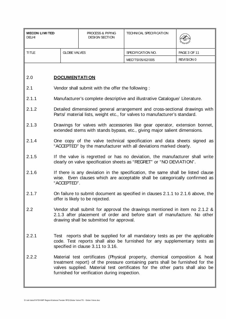
D:\old data\FATEH\MP Region\Kailaras\Tender RFQ\Globe Valve\TS - Globe Valve.doc
MECON LIMITEDDELHI
PROCESS & PIPINGDESIGN SECTION
TECHNICAL SPECIFICATION
TITLE GLOBE VALVES SPECIFICATION NO. PAGE 3 OF 11
MEC/TS/05/62/005 REVISION 0
2.0 DOCUMENTATION
2.1 Vendor shall submit with the offer the following :
2.1.1 Manufacturer’s complete descriptive and illustrative Catalogue/ Literature.
2.1.2 Detailed dimensioned general arrangement and cross-sectional drawings withParts/ material lists, weight etc., for valves to manufacturer’s standard.
2.1.3 Drawings for valves with accessories like gear operator, extension bonnet,extended stems with stands bypass, etc., giving major salient dimensions.
2.1.4 One copy of the valve technical specification and data sheets signed as“ACCEPTED” by the manufacturer with all deviations marked clearly.
2.1.5 If the valve is regretted or has no deviation, the manufacturer shall writeclearly on valve specification sheets as “REGRET” or “NO DEVIATION”.
2.1.6 If there is any deviation in the specification, the same shall be listed clausewise. Even clauses which are acceptable shall be categorically confirmed as“ACCEPTED”.
2.1.7 On failure to submit document as specified in clauses 2.1.1 to 2.1.6 above, theoffer is likely to be rejected.
2.2 Vendor shall submit for approval the drawings mentioned in item no 2.1.2 &2.1.3 after placement of order and before start of manufacture. No otherdrawing shall be submitted for approval.
2.2.1 Test reports shall be supplied for all mandatory tests as per the applicablecode. Test reports shall also be furnished for any supplementary tests asspecified in clause 3.11 to 3.16.
2.2.2 Material test certificates (Physical property, chemical composition & heattreatment report) of the pressure containing parts shall be furnished for thevalves supplied. Material test certificates for the other parts shall also befurnished for verification during inspection.
D:\old data\FATEH\MP Region\Kailaras\Tender RFQ\Globe Valve\TS - Globe Valve.doc
MECON LIMITEDDELHI
PROCESS & PIPINGDESIGN SECTION
TECHNICAL SPECIFICATION
TITLE GLOBE VALVES SPECIFICATION NO. PAGE 4 OF 11
MEC/TS/05/62/005 REVISION 0
3.0 DESIGN AND CONSTRUCTION
3.1 Valves shall be designed, manufactured, tested, inspected and marked as perthe manufacturing standards design codes and standards (Latest editions)indicated in the respective valve specification sheets. Any conflict between thethe technical specifiction, specification sheets and referred standard codes shallbe brought to the notice of the purchaser for clarifications, but generallytechnical specification, data sheets shall govern. No deviation to specification/standard shall be permitted through vendor drawings approval. Approval ofdrawings shall be valid only for design features.
3.2 Bonnet extension wherever specification the valve sheet to BS : 6364 shall befor “Non Cold Box Application” unless otherwise specified in the requisition.Even if not called for in valve sheet, valves indicated as ‘CRYO’ shall besupplied with bonnet extension.
3.3 For heavy valves provisions shall be available for lifting by way of lugs, eyebolts and such standard devices.
3.4 All flanged valves shall have flanges integral (except forged valves) with thevalve body. Flange finish shall be as per valve specification sheet.
3.5 For all weld end valves with bevel end as per ANSI B16. 25.
The contour of bevel shall be as follows :
Material Wall Thickness Weld Contour
Carbon steel upto 22 mm figure 2 type A(Except low temp. > 22 mm figure 3 type Acarbon steel )Alloy steel, upto 10 mm figure 4Stainless steel & > 10 mm to 25 mm figure 5 type Alow temp. carbon steel > 25 mm figure 6 type A
3.6 If an overlay weld-deposit is used for the body seat ring and seating surface,the seat ring base material shall be at least equal to the corrosion resistance ofthe material of the shell.
D:\old data\FATEH\MP Region\Kailaras\Tender RFQ\Globe Valve\TS - Globe Valve.doc
MECON LIMITEDDELHI
PROCESS & PIPINGDESIGN SECTION
TECHNICAL SPECIFICATION
TITLE GLOBE VALVES SPECIFICATION NO. PAGE 5 OF 11
MEC/TS/05/62/005 REVISION 0
3.7 Valve body/ bonnet shall be forged/ cast as specified. Forging is acceptable inplace of casting but not vice-versa.
3.8 Material of construction of yoke shall be minimum equivalent to body/ bonnetmaterial.
3.9 Stem shall be forged or machined from forged / rolled bar. No casting ispermitted, .
3.10 Stelliting / hard facing by deposition shall be minimum 1.6 mm. Renewableseat ring may be seal welded.
3.11 As a pre qualification low temperature carbon steel, (LTCS), 3 ½ Ni steel(CRYO) & austenitic stainless (CRYO) valves shall be subjected to cryogenictest as per BS 6364 and test shall be witnessed and certified by third partyinspection agency like Lloyds, B.V., DNV or EIL. For INDIAN vendors,inspection agency shall be MECON only. The vendor has to submit testcertificate for prototype valves along with the offer. Prototype test carried on aparticular size, rating and design will qualify valves of sizes equal to and belowthe particular size of the same rating and design.
Cryogenic testing as per BS 6364 shall be carried out at temperature (-45 °C),(-100 °C) & (-196 °C ) for “LTCS”, 3 ½ Ni steel (CRYO) & austenitic stainlesssteel “CRYO” valves respectively.
3.12 Repair welding procedure for austenitic stainless steel valves in ‘CRYO’ serviceshall have to be qualified for impact test as per ANSI B31.3. Minimumacceptable impact energy shall be 20J or lateral expansion of 0.38 mm at tempof -196 Deg C
3.13 Wherever impact test of SS studs/ nuts is called for in the data sheet, theimpact value shall be 27J at the intended service temperature specified in thedata sheets.
3.14 For all austenitic stainless steel valves Inter Granular Corrosion (IGC) test shallhave to be conducted as per following :
- ASTM A 262 practice “B” with acceptance criteria of “60 Mills/ Year (Max.)” –For all materials forged, rolled, wrought and casting.
D:\old data\FATEH\MP Region\Kailaras\Tender RFQ\Globe Valve\TS - Globe Valve.doc
MECON LIMITEDDELHI
PROCESS & PIPINGDESIGN SECTION
TECHNICAL SPECIFICATION
TITLE GLOBE VALVES SPECIFICATION NO. PAGE 6 OF 11
MEC/TS/05/62/005 REVISION 0
OR
- ASTM A 262 practice “E” with acceptance criteria of “No cracks as observedform 20X magnification” – For all materials other than castings. “Microscopicstructure to be observed form 250X magnification” in addition.
3.15 When specifically asked for in MR for high temperature application of somegrades of austenitic stainless steel (eg. SS309, 310, 316, 316H etc.) ASTM A262 practice “C” with acceptance criteria of “15 Mils/ Year – (Max.)” shall haveto be conducted.
3.16 For the IGC test as described in 3.14 & 3.15 two sets of samples shall bedrawn from each solution annealing lot, one set corresponding to highestcarbon content and other set corresponding to highest pressure rating
3.17 Spiral wound bonnet gasket are to be provided with inner/ outer ring exceptwhen encapsulated gaskets type body- bonnet joints are employed. Outer ringmay be avoided in case of Non- circular spiral wound gasket used in 150#valve provided the outermost layer of spiral touches the bolts ascertaining thecentering.
4.0 OPERATION
4.1 Generally the valves are hand wheel of lever operated. Gear operation shall beprovided as under :
Class Size RequiringGear Operator
900 # 6” and Larger1500 # 3” and Larger2500 # 3” and Larger
For sizes lower than these ranges, hand wheel shall be provided.
4.2 Gear operator shall be totally enclosed bevel gear in grease case with greasenipples/ plugs with position indicators for open / close position.
D:\old data\FATEH\MP Region\Kailaras\Tender RFQ\Globe Valve\TS - Globe Valve.doc
MECON LIMITEDDELHI
PROCESS & PIPINGDESIGN SECTION
TECHNICAL SPECIFICATION
TITLE GLOBE VALVES SPECIFICATION NO. PAGE 7 OF 11
MEC/TS/05/62/005 REVISION 0
4.3 Where gear operator is not called for as per clause 4.1 but vendorrecommends a gear operator, he shall highlight such case/s and quoteseparate prices for the valve and gear operator.
4.4 Gear operator shall be so designed to operate effectively with the differentialpressure across the closed vale equal to the cold non-shock pressure rating.
4.5 Hand wheel diameter shall not exceed 750 mm and lever length shall notexceed 500 mm. on both sides. Effort to operate shall not exceed 35 kgs athand wheel periphery. However failing to meet the above requirements vendorshall offer gear operated valve and quote as per clause 4.3.
5.0 INSPECTION AND TESTING
5.1 Every valve shall be subjected to all the mandatory tests and checks called inthe respective codes/ data sheet.
5.2 Every valve, its components and auxiliaries be subjected to all the mandatorytests and checks called in the respective codes, data sheets etc. by themanufacturer.
5.3 Though the extent of inspection by purchaser or his authorised representativeshall be as under, however exact extent with hold points shall be decided byMECON and recorded in the form of inspection plan.
FORGED VALVES :
1) Visual and dimensional inspection.
2) Review of material test certificates.
3) Any mandatory or supplementary test.
4) Hydrostatic test on 10% valves selected on random basis.
5) Strip check as applicable for valves
D:\old data\FATEH\MP Region\Kailaras\Tender RFQ\Globe Valve\TS - Globe Valve.doc
MECON LIMITEDDELHI
PROCESS & PIPINGDESIGN SECTION
TECHNICAL SPECIFICATION
TITLE GLOBE VALVES SPECIFICATION NO. PAGE 8 OF 11
MEC/TS/05/62/005 REVISION 0
CAST STEEL VALVES :
1) Visual and dimensional inspection.2) Review of material test certificates.3) Review of radiographs/ radiographic reports of any other NDT
tests wherever applicable as per data sheet.4) Any mandatory or supplementary test.5) Hydrostatic test. 100% for body, 10% other test.6) Strip check as applicable for valves.
5.4 In case of motor operated or actuator operated valves, functional/operationalchecks as per the requirements of the specifications shall be made on eachvalve.
6.0 RADIOGRAPHY OF CAST VALVES
6.1 Valves under critical, very highly critical, lethal and toxic services shall beradiographed as specified in respective data sheets When specifically notmentioned in individual data sheet, valve casting shall undergo radiographicexamination as specified hereunder :
...........................................................................................................Material Rating Size Range Radiography...........................................................................................................All 150 # 24” And Below Nil
150 # 26” And Above 100%300 # 16” And Below Nil300 # 18” And Above 100%600 # All Sizes 100%& Above
...........................................................................................................
6.2 Radiography procedure, areas of casting to be radiographed shall be a per ANSIB-16.34 and acceptance criteria shall be as per ANSI B-16.34 Annexure-B.However for areas of casting to be radio-graphed for types of valve not coveredin ANSI B-16.34, vendor shall enclose details of areas to be radiographed in linewith ANSI B-16.34.
6.3 Random radiography wherever specified in individual data sheets, the samplingshall be per size of the quantity ordered for each foundry.
D:\old data\FATEH\MP Region\Kailaras\Tender RFQ\Globe Valve\TS - Globe Valve.doc
MECON LIMITEDDELHI
PROCESS & PIPINGDESIGN SECTION
TECHNICAL SPECIFICATION
TITLE GLOBE VALVES SPECIFICATION NO. PAGE 9 OF 11
MEC/TS/05/62/005 REVISION 0
6.4 Radiography wherever specified in the data sheets or as per clause 6.1 shall bedone by X-Ray/ Gamma-Ray to get the required sensitivity.
6.5 Over and above the stipulation laid down in clauses 6.1, 6.2, 6.3 & 6.4, all valvecastings shall only be procured among the foundries after obtaining approvalfrom Client / Consultant.
7.0 IBR CERTIFICATION
7.1 For valves described “IBR” valves shall be in accordance with the latest IBR(Indian Boiler Regulation) including the requirements specified in thespecification.
7.2 SW/ BW end carbon steel valves under IBR< the chemical composition shallconform to the following :
Carbon (Max) : 0.25%Others (S,P, Mn) : As per IBR regulations
7.3 For valves described “IBR” test certificate in form III-C shall be furnished,signed by IBR inspection authority or an approved representative.
7.4 All “IBR” valves shall be painted red in body-bonnet/ body cover joint.
8.0 QUALITY ASSURANCE PLAN (QAP)
8.1 Procurement of Bought out Materials
All critical materials such as casting, forging, pressure holding parts, electricaland instrument accessories, etc. shall be purchased by the Vendor from GAIL/MECON approved suppliers meeting Qualification Criteria stipulated if any.Vendor shall submit a list of bought out materials and sub-vendors for thesebought out materials for MECON approval within 2 weeks from Telefax/ Letterof Intent.
8.2 Calibration Records
Vendor shall use only calibrated measuring and test instruments and maintaincalibration records. Vendor shall furnish records of calibration of measuring andtest instruments including re calibration records to concerned InspectionAuthority.
D:\old data\FATEH\MP Region\Kailaras\Tender RFQ\Globe Valve\TS - Globe Valve.doc
MECON LIMITEDDELHI
PROCESS & PIPINGDESIGN SECTION
TECHNICAL SPECIFICATION
TITLE GLOBE VALVES SPECIFICATION NO. PAGE 10 OF 11
MEC/TS/05/62/005 REVISION 0
8.3 Quality Records
Vendor shall maintain quality records as per approved procedures. InspectionReports & Test Record. Copies shall be furnished to Inspection Authority.
8.4 Final Documentation
8.4.1 Final drawings/ documents consisting of technical data manual/ mechanicalcatalogue is a compilation of “as built” certified, drawings and data,manufacturing and test records, installation, operating and maintenanceinstructions. For drawings where Purchaser’s approval is required, the final certified drawings shall be included. Final documents shall be legiblephotocopies in A4, A3 or A2 size only. The purchase requisition shall also forma part of the final documentation.
8.4.2 Final documentation shall be bound in Hard board folder(s) of size 265 mm x315 mm (10½” x 12½”) and shall not be more than 90 mm thickness.
9.0 MARKING
9.1 Valve markings, symbols, abbreviations etc. shall be in accordance with MSS-SP-25 or the standard referred in specification sheet as applicable. Vendorsname, valve rating, material designation, nominal size, direction of flow (if any)etc. shall be integral on the body.
9.2 Each valve shall have a corrosion resistant tag giving size, valve tag / code no,securely attached on the valve body.
9.3 Paint or Ink for marking shall not contain any harmful metal or metal saltssuch as zinc, lead or copper which causes corrosive attack on heating.
9.4 Carbon steel valves shall be painted with coats of red oxide zinc chromateprimer or single coat of aluminum paint. Forged valves supplied chemicallyblackened (phosphated) is also acceptable.
9.5 All alloy steel high temp valves shall be painted with heat resistant siliconepaint suitable for intended temperature.
D:\old data\FATEH\MP Region\Kailaras\Tender RFQ\Globe Valve\TS - Globe Valve.doc
MECON LIMITEDDELHI
PROCESS & PIPINGDESIGN SECTION
TECHNICAL SPECIFICATION
TITLE GLOBE VALVES SPECIFICATION NO. PAGE 11 OF 11
MEC/TS/05/62/005 REVISION 0
9.6 All 3 ½ Ni Steel / LTCS valves shall be painted with one coat of inorganic zincsilicate coating.
10.0 DESPATCH
10.1 Valves shall be dry, clean and free from moisture, dirt and loose foreignmaterials of any kind.
10.2 Valves shall be protected from rust, corrosion and any mechanical damageduring transportation, shipment and storage.
10.3 Rust preventive on machined surfaces to be welded shall be easily removablewith a petroleum solvent or not harmful to welding.
10.4 Each end of valves shall be protected with the following materials :
Flange face : Wood, Metal or Plastic coverBevelled end : Wood, Metal or Plastic coverSW & Scrd. End : Plastic cap
10.5 End protectors to be used on flange faces shall be attached by at least threebolts or wiring through bolt holes and shall not be smaller than the outsidediameter of the flange. However plastic caps for SW & SCRD. End valves shallbe press fit type.
10.6 End protectors to be used on beveled end shall be securely and tightlyattached.
10.7 For special service valves additional requirement of despatch shall beprescribed in data sheet.
D:\old data\FATEH\MP Region\Kailaras\Tender RFQ\TCP&PCP\Temporary Cathodic Protection - 016A-R1.doc
PROCESS & PIPING DESIGN SECTIONMECON LIMITEDDELHI - 110 092
TECHNICAL SPECIFICATIONFOR
TEMPORARY CATHODIC PROTECTION SYSTEM
SPECIFICATION NO. : MEC/TS/05/62/016A, R-1
MECON LIMITEDDelhi
PROCESS & PIPINGDESIGN SECTION
TECHNICAL SPECIFICATION FORTEMPORARY CATHODICPROTECTION SYSTEM
TECHNICAL SPECIFICATION NO. : MEC/TS/05/62/016A REV-1 Page 1 of 19
D:\old data\FATEH\MP Region\Kailaras\Tender RFQ\TCP&PCP\Temporary Cathodic Protection - 016A-R1.doc
C O N T E N T S
Sl.No. Description Page No.
1.0 SCOPE
2.0 CODES AND STANDARDS
3.0 CORROSION DATA
4.0 CATHODIC PROTECTION DESIGN PARAMETERS
5.0 CATHODIC PROTECTION DESIGN CRITERIA
6.0 SYSTEM DETAILS
7.0 INSTALLATION
8.0 CIVIL WORKS
9.0 TESTING AND INSPECTION AT WORKS
10.0 PACKING AND TRANSPORT
11.0 SYSTEM TESTING COMMISSIONING AND INTERFERENCE MITIGATION
12.0 SYSTEM MONITORING
13.0 DRAWINGS AND DOCUMENTS
14.0 INSTRUMENTS, TOOLS AND SPARES
15.0 INFORMATION REQUIRED WITH BID
MECON LIMITEDDelhi
PROCESS & PIPINGDESIGN SECTION
TECHNICAL SPECIFICATION FORTEMPORARY CATHODICPROTECTION SYSTEM
TECHNICAL SPECIFICATION NO. : MEC/TS/05/62/016A REV-1 Page 1 of 19
D:\old data\FATEH\MP Region\Kailaras\Tender RFQ\TCP&PCP\Temporary Cathodic Protection - 016A-R1.doc
1.0 SCOPE
1.1 This specification defines the requirements of design, engineering supply of materials,installation, testing and commissioning of temporary cathodic protection system ofexternal surface of cross country underground pipeline/structure includingsupplementing of corrosion survey, investigation for interference/ interaction problemsand mitigation of the same. Unless otherwise specified monitoring of the temporarycathodic protection system till the commissioning of permanent C.P. System shall becarried out by temporary C.P. contractor.
This specification defines the basic guidelines to develop a suitable temporary cathodicprotection system for the structure required to be protected. All data required in thisregard shall be taken into consideration to develop an acceptable design and forproper engineering of the system.
1.2 Compliance with these specifications and/ or approval of any of the contractor'sdocuments shall in no case relieve the contractual obligations.
1.3 In case where temporary and permanent cathodic protection works are beingexecuted by the same agency, activities of permanent CP system which are commonto temporary CP system shall be completed as part of temporary CP system. In caseswhere temporary and permanent cathodic protection works are being executed bydifferent agencies, the contractual scope of work shall be referred for further details.
1.4 All work to be performed and supplies to be effected as a part of contract shall requirespecific approval of owner or his authorised representative. Major activities requiringapproval shall include but not be limited to the following :-
• Corrosion survey data interpretation report and design basis for CP system.• CP system design package• Purchase requisitions for major equipment and vendor approval• Detailed engineering package• Field testing and commissioning procedure• Procedures for interference testing and mitigation• CPL survey and system monitoring procedures
2.0 CODES AND STANDARDS
The system design, performance and materials to be supplied shall unless otherwisespecified, conform to the requirements of latest relevant applicable standards of :-
BIS specificationsBS specifications and codes of practiceANSI specificationsNFPA publications
MECON LIMITEDDelhi
PROCESS & PIPINGDESIGN SECTION
TECHNICAL SPECIFICATION FORTEMPORARY CATHODICPROTECTION SYSTEM
TECHNICAL SPECIFICATION NO. : MEC/TS/05/62/016A REV-1 Page 2 of 19
D:\old data\FATEH\MP Region\Kailaras\Tender RFQ\TCP&PCP\Temporary Cathodic Protection - 016A-R1.doc
NACE publicationsIEC publicationsDNV publicationsIEEE publicationsDIN publicationsASTM publications
In case of conflicting requirements amongst any of the above standards thepublication having most stringent requirement shall be governing.
3.0 CORROSION DATA
3.1 The corrosion survey including soil resistivity data along ROW and other data requiredfor CP design is attached with this document. However, verification of its veracity andadequacy shall be the entire responsibility of the contractor. In addition, contractorshall have to generate/ collect additional data as required for completeness of the job.Contractor shall also carry out soil resistivity survey at temporary mode ground bedlocations for proper design of ground beds. Wenner's 4-pin method or approved equalshall be used for such measurements. Survey instruments shall have maximum AC andDC ground current rejection feature.
3.2 Additional data to be collected
The following data shall be collected to generate design data for evaluation ofinteraction/ interference possibilities due to presence of other services in ROW/ invicinity.
i. Route and types of foreign service/pipeline in and around or crossing the rightof way (including those existing and those which are likely to come up duringcontract execution or any abandoned pipelines.
ii. Diameter, wall thickness, pressure, pipeline coating against corrosion, soilcover used in case of pipelines.
iii. Detail of the existing cathodic protection system protecting the services i.e.location, rating, type of protection, anode beds, test station locations and theirconnection schemes.
iv. Graphical representation of existing structure/ pipe-to soil potential records.T/R unit current/ voltage readings.
v. Remedial measures existing on foreign pipeline/services to prevent interaction.
vi. Possibility of intergration/isolation of CP system, Which may involvenegotiations with owners of other services.
MECON LIMITEDDelhi
PROCESS & PIPINGDESIGN SECTION
TECHNICAL SPECIFICATION FORTEMPORARY CATHODICPROTECTION SYSTEM
TECHNICAL SPECIFICATION NO. : MEC/TS/05/62/016A REV-1 Page 3 of 19
D:\old data\FATEH\MP Region\Kailaras\Tender RFQ\TCP&PCP\Temporary Cathodic Protection - 016A-R1.doc
vii. Crossing and parallel running of electrified and non-electrified traction (alongwith information regarding operating voltage, type AC/DC etc.) as well asabandoned tracks near ROW having electrical continuity with the tracks in use.
viii. Crossing and parallel running of any HT/AC/DC overhead line(existing/proposed) along with details of voltage, type AC/DC etc.
ix. Voltage rating, number of cores and sheathing details of under ground powercables, along ROW or in its vicinity.
x. Information on existing and proposed DC/AC power sources and system havingearth as return path, in the vicinity of the entire pipeline, route such as HV/DCsub stations, fabrication yards with electric welding etc.
xi. Any other relevant information that may be needed in designing andimplementing proper protection scheme for the proposed pipeline.
Unless otherwise mentioned, Contractor shall condut necessary potentialgradient survey for any existing anode ground bed that may interfere with theCP system of the pipeline covered under this project.
xii. Any masonry work for other concrete or non conductive constructions in theROW which may block the CP current or cause interference to the pipeline.
xiii. Any underground cable running in parallel or crossing the ROW.
3.3 Report
On completion of all field work a report incorporating all the results generated fromsurveys and details of additional data collected shall be furnished. The report shall alsocontain detailed interpretation of survey results and resistivity data enclosed, probableinterference prone areas etc. to form design basis for the scheme of cathodicprotection. This report shall be plotted on semi-log graph sheets.
4.0 CATHODIC PROTECTION DESIGN PARAMETERS
Unless otherwise specified in the project specifications, following parameters shall beused for design of temporary cathodic protection system.
Those parts of sacrificial anode cathdic protection system which will be integrated withpermanent CP system shall be designed based on permanent CP parameters.
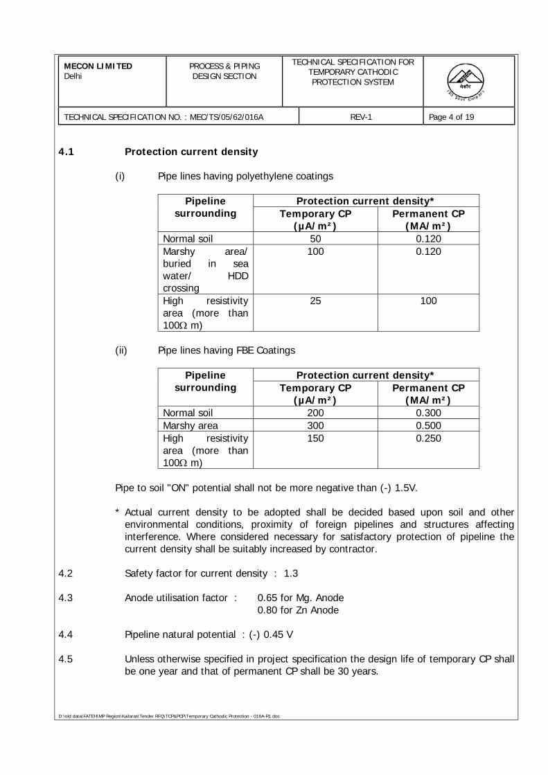
MECON LIMITEDDelhi
PROCESS & PIPINGDESIGN SECTION
TECHNICAL SPECIFICATION FORTEMPORARY CATHODICPROTECTION SYSTEM
TECHNICAL SPECIFICATION NO. : MEC/TS/05/62/016A REV-1 Page 4 of 19
D:\old data\FATEH\MP Region\Kailaras\Tender RFQ\TCP&PCP\Temporary Cathodic Protection - 016A-R1.doc
4.1 Protection current density
(i) Pipe lines having polyethylene coatings
Protection current density*Pipelinesurrounding Temporary CP
(µA/m²)Permanent CP
(MA/m²)Normal soil 50 0.120Marshy area/buried in seawater/ HDDcrossing
100 0.120
High resistivityarea (more than100Ω m)
25 100
(ii) Pipe lines having FBE Coatings
Protection current density*Pipelinesurrounding Temporary CP
(µA/m²)Permanent CP
(MA/m²)Normal soil 200 0.300Marshy area 300 0.500High resistivityarea (more than100Ω m)
150 0.250
Pipe to soil "ON" potential shall not be more negative than (-) 1.5V.
* Actual current density to be adopted shall be decided based upon soil and otherenvironmental conditions, proximity of foreign pipelines and structures affectinginterference. Where considered necessary for satisfactory protection of pipeline thecurrent density shall be suitably increased by contractor.
4.2 Safety factor for current density : 1.3
4.3 Anode utilisation factor : 0.65 for Mg. Anode0.80 for Zn Anode
4.4 Pipeline natural potential : (-) 0.45 V
4.5 Unless otherwise specified in project specification the design life of temporary CP shallbe one year and that of permanent CP shall be 30 years.
MECON LIMITEDDelhi
PROCESS & PIPINGDESIGN SECTION
TECHNICAL SPECIFICATION FORTEMPORARY CATHODICPROTECTION SYSTEM
TECHNICAL SPECIFICATION NO. : MEC/TS/05/62/016A REV-1 Page 5 of 19
D:\old data\FATEH\MP Region\Kailaras\Tender RFQ\TCP&PCP\Temporary Cathodic Protection - 016A-R1.doc
5.0 CATHODIC PROTECTION DESIGN CRITERIA
5.1 Cathodic protection system shall be designed to meet the following criteria:
a) the pipe to electrolyte Potential measurement shall be – 9S150 MV ormorenigative as measured between pipe surface and saturated CU-CU 804,reference electrode containing electroly when cathodic protection is applied buton potential measurement shall not go more negative than than (-) 1500 MV.
b) The pipeline shall be considered protected when a minimum of (-) 300 millivoltpotential potential shift has been achieved from the initial native potential to theCP `ON’ potential.
c) In rare circumstances a minimum polarisation shift of (-) 100 millivolts shallindicate adequate levels of cathodic protection for the pipeline. The formation ofdecary of this polarisation shall be used in the criteria.
Discretion to use any of the criteria listed above shall solely rest with theOwner/ Owner’s representative.
5.2 A positive potential swing of 50-100 mV shall be considered the criteria for presence ofan interaction situation requiring investigation and incorporation of mitigation measuresby the CONTRACTOR.
6.0 SYSTEM DETAILS
The system shall include the following major equipment/sub-systems unless otherwisespecified:
- Sacrificial anodes and anode ground beds- Test stations- Surge diverter/grounding cell- Polarisation cells- Interconnecting cables- Cable to pipe connections- Spark Gap Arrester
All equipment shall be new and supplied by approved reputed manufacturers.Equipment offered shall be field proven. Equipment requiring specialised maintenanceor operation shall be avoided as far as possible and prototype equipment shall not beaccepted. Make and construction of all material shall be subject to owner's approval.
The detailed specification of each system and equipment shall be furnished by thecontractor. However, certain minimum requirements for the major equipment arehighlighted in this document.
MECON LIMITEDDelhi
PROCESS & PIPINGDESIGN SECTION
TECHNICAL SPECIFICATION FORTEMPORARY CATHODICPROTECTION SYSTEM
TECHNICAL SPECIFICATION NO. : MEC/TS/05/62/016A REV-1 Page 6 of 19
D:\old data\FATEH\MP Region\Kailaras\Tender RFQ\TCP&PCP\Temporary Cathodic Protection - 016A-R1.doc
As far as possible equipment including test stations, anode lead junction boxes, etc.,shall be located in safe area. All equipment located in hazardous areas shall be offlame proof type as per IS:2148 for gas groups IIA & IIB and temp. class T3.
6.1 Anode Ground Beds
6.1.1 The pipeline shall be protected by prepacked zinc/ magnesium anodes.
6.1.2 Anodes shall be installed along the pipeline at suitable intervals as per pipeline protectionvoltage attenuation calculations and ground bed resistance/ current output of anodeinstallations. Minimum one anode installation shall be provided for every one km. of thepipeline. In congested area, minimum one anode installation shall be provided for every250 meter of pipeline length.
6.1.3 Each electrically continuous section of pipeline shall preferably be protected totally by onetype (material) of anodes to avoid inter-anode circulation currents.
6.1.4 The anodes shall be installed at sufficient depth to reach moist soil and shall beseparated from the pipe line by at least 5m and 2m for magnesium and zinc anodesrespectively. The anode connections to pipeline shall be routed through test stations.
6.1.5 At the temporary cathodic protection anode ground bed, the leads of all the anodes shallbe joined together in a junction box filled with epoxy and buried. A single cable shall berouted from the junction box to the test station. At permanent CP anode ground bed (i.e.at cased crossing), the leads of all the anodes shall be brought up to the test station andshall be terminated individually.
6.1.6 For sacrificial anode ground bed which shall be integrated with permanent CP System theleads of all the anodes shall be brought up to the test station and shall be terminatedindividually.
6.1.7 The number of anodes at each ground bed shall be sufficient for providing the specifiedpipe protection current density taking into consideration the ground bed resistance, pipecoating resistance, cable resistance, etc. Contractor shall prepare a table for number ofanodes required at different soil resistivities to produce the specified protection current.
6.2.1 Magnesium anode
The anode shall be of high manganese, magnesium alloy packed with special back fill.The metallurgical composition, potential and consumption rate of anode shall be asbelow:
MECON LIMITEDDelhi
PROCESS & PIPINGDESIGN SECTION
TECHNICAL SPECIFICATION FORTEMPORARY CATHODICPROTECTION SYSTEM
TECHNICAL SPECIFICATION NO. : MEC/TS/05/62/016A REV-1 Page 7 of 19
D:\old data\FATEH\MP Region\Kailaras\Tender RFQ\TCP&PCP\Temporary Cathodic Protection - 016A-R1.doc
(i) Composition:
Element Weight
Manganese 0.5 – 1.3%Copper 0.02% max.Silicon 0.05% max.Zinc 0.05% max.Aluminum 0.01% max.Iron 0.03% max.Nickel 0.001% max.Other metallic elements
- Each 0.05% max.- Total 0.3%
Magnesium Balance
(ii) Anode closed circuit potential 1.5 volts
(iii) Anode consumption rate 7.9 kg/(A yr)
6.2.2 Zinc Anode
The anode shall confirm to the requirements of ASTM – 418 standard. The anode(other than ribbon anode) shall be packaged with special back fill. The metallurgicalcomposition of anode, potential and consumption rate shall be as below:
(i) Composition:
Element WeightAluminium 0.005%Cadmium 0.0035%Copper 0.002% max.Iron 0.0014% max.Lead 0.0035% max.Zinc Remainder
(ii) Anode closed circuit potential 1.1 volts
(iii) Anode consumption rate 11.24 kg/(A yr)
MECON LIMITEDDelhi
PROCESS & PIPINGDESIGN SECTION
TECHNICAL SPECIFICATION FORTEMPORARY CATHODICPROTECTION SYSTEM
TECHNICAL SPECIFICATION NO. : MEC/TS/05/62/016A REV-1 Page 8 of 19
D:\old data\FATEH\MP Region\Kailaras\Tender RFQ\TCP&PCP\Temporary Cathodic Protection - 016A-R1.doc
6.2.3 Contractor shall furnish spectographic analysis from each heat both for zinc andmagnesium anodes along with electrochemical test results.
6.2.4 Special Backfill
The composition of special back fill for anodes shall be as below:
Gypsum 75%Bentonite 20%Sodium Sulphate 5%
6.2.5 The anodes shall be provided with cable tail of sufficient length to reach junction boxtest station as applicable without tension.
6.2.6 Tolerance in fabrication of anodes
The anode surface shall be free from cracks which may reduce the performance of theanode.
Any cracks which follow the longitudinal direction of elongated anodes shall not beacceptable.
Small cracks in the transverse direction of elongated anodes and in anodes of othershapes may be accepted provided the cracks would not cause any mechanical failureduring service of the anode considering that the combination of cracks and lack ofbond to the anode core is detrimental.
For transverse cracks the acceptable limits shall be furnished by the bidders along withthe offer.
The anode shall be free from excessive shrinkages. The following limits shall be used:
- Maximum 10% of the depth of anode or 50% of the depth of the anode corewhichever is less. The depression may be measured from the edged of oneside.
The surface of the anodes shall be free from coatings and slag/dross inclusions etc.
The maximum deviation from straightness shall not exceed 2%.
The weight tolerance on individual anodes may be taken as ± 5%. The total weight ofthe anodes shall not have negative tolerance.
MECON LIMITEDDelhi
PROCESS & PIPINGDESIGN SECTION
TECHNICAL SPECIFICATION FORTEMPORARY CATHODICPROTECTION SYSTEM
TECHNICAL SPECIFICATION NO. : MEC/TS/05/62/016A REV-1 Page 9 of 19
D:\old data\FATEH\MP Region\Kailaras\Tender RFQ\TCP&PCP\Temporary Cathodic Protection - 016A-R1.doc
Recommended dimensional tolerance shall be as follows:
Length ± 2.5%Width/thickness ± 5%
6.3 Test Stations
6.3.1 Test stations shall be provided along the pipeline ROW for monitoring the performanceof the Cathodic Protection system at intervals not exceeding 1000 meters inuncongested & 250 meters in congested area unless otherwise specified. In additionto above, test stations shall also be provided at the following locations:
a. At both sides of major road crossingsb. At all insulating jointsc. At vulnerable locations with drastic changes in soil resistivityd. At connections of surge diverters, grounding cells and polarisation cellse. At HT AC/DC overhead line crossings and selected locations where HT
overhead line is in the vicinity of the pipeline.f. At railway line crossings and running parallel to the pipeline.g. At both sides of major river crossings.h. At high voltage cable crossings or along routes where HV cables are running in
parallel.i. In the vicinity of DC net works or grounding system where interference
problems are suspected.j. At crossings/parallel running of other pipeline structuresk. At both sides of cased crossingsl. At any other locations considered vulnerable locations where interference is
expectedm. At any other locations considered necessary by owner/owner’s representative
6.3.2 Test stations for bonding shall be provided with shunt and resistor as a means tomonitor and control current.
6.3.3 Test stations used for sacrificial anodes shall have shunt for measurement of anodecurrent, and provision for resistance insertion to limit the anode current output.
6.3.4 Test station with current measuring facility shall be provided at each intermediate CPstation drainage point (to measure pipeline from drainage point), at interference proneareas, on both sides of major river crossings and at least at two additional locationsalong the pipeline ROW between two CP stations.
6.3.5 All test stations shall have weather proof enclosure, having degree of protection IP 55with hinged lockable shutter. Enclosure shall be made of sheet steel of at least 3 mmthickness and shall be suitable for M.S. post mounting. The test stations shall be
MECON LIMITEDDelhi
PROCESS & PIPINGDESIGN SECTION
TECHNICAL SPECIFICATION FORTEMPORARY CATHODICPROTECTION SYSTEM
TECHNICAL SPECIFICATION NO. : MEC/TS/05/62/016A REV-1 Page 10 of 19
D:\old data\FATEH\MP Region\Kailaras\Tender RFQ\TCP&PCP\Temporary Cathodic Protection - 016A-R1.doc
designed with terminals required for both temporary and permanent CP system andshall be suitable for total life of permanent CP system.
6.3.6 The test stations shall be installed with the front of the test station facing the pipeline.The name plate of test stations shall in minimum carry following information.
- Test station number- Chainage in km- Test station connection scheme type- Distance from pipeline in meters- Direction of product flow
6.3.7 Terminal blocks and different scheme of wiring as required shall be provided in thetest station as per the test station connection scheme sketch.
6.3.8 The location of all the test stations shall be marked with their connection schemes andother relevant information's on alignment sheets. A detailed test station schedule shallbe prepared.
6.4 Surge diverter, grounding cell and polarisation cell
6.4.1 Where high voltage (66 KV and above) transmission line runs in parallel or crosses thepipeline, the pipeline shall be grounded through polarisation cells & zinc anodes ofminimum 20 kg net each. Alternatively, grounding could be done directly with zincgalvanic anodes of minimum 20 kg net each at the discretion of owner. Groundingshall be done at regular intervals where transmission lines run parallel within 25 meterof the pipeline to ground any surges on the pipeline that would appear in case oftransmission line faults.
6.4.2 In case of continuous induction of voltage on the pipeline beyond safe limits isexpected or observed during commissioning due to HV Line or other of any rating., thepipeline shall be grounded to the earth system of nearest HV transmission tower ofthe transmisison line causing the voltage induction through polarisation cell or thepipeline shall be grounded to a separate earthing system of zinc galvanic anodesthrough polarisation cell. Alternatively, the pipeline shall be directly grounded withzinc galvanic anodes of minimum 20 kg net each at the discretion of the owner. Thepolarisation cell shall be installed in test station.
6.4.3 Spark gap arrestor shall be connected across each insulating joint to protect in fromhigh voltage surges.
6.4.4 Alternatively, zinc grounding cell may be provided across insulating joints along ROWwhere the pipeline on both the sides of the insulating joint are cathodically protectedand difference of protection voltage is not more then 0.4 volts.
MECON LIMITEDDelhi
PROCESS & PIPINGDESIGN SECTION
TECHNICAL SPECIFICATION FORTEMPORARY CATHODICPROTECTION SYSTEM
TECHNICAL SPECIFICATION NO. : MEC/TS/05/62/016A REV-1 Page 11 of 19
D:\old data\FATEH\MP Region\Kailaras\Tender RFQ\TCP&PCP\Temporary Cathodic Protection - 016A-R1.doc
Alternatively, owner on its own discretion may permit use of Magnesium / Zincgalvanic anodes for protection of insulating joints. Choice between Magnesium or zincanodes shall depend upon the potential valves on either side of the insulating joint.These anodes shall be sized for the specified design life of permanent cathodicprotection system.
6.4.5 The total system including cables, cable termination, anodes/ surge divertors shall besuitable for the anticipated fault current at the location of installation.
6.4.6 Unless otherwise specified on data sheet, the minimum rating of grounding cells,polarisation cells and surge diverters shall be as below:
(i) Grounding Cell- Type : Zinc, 2 or 4 plate type- Current rating : Suitable to pass more than
10kA surge
(ii) Polarisation cell- Type : Solid state or Electrolytic multiple pairs
S.S plats type ground- Rating : Suitable to pass 5KA or more surge
(iii) Spark Gap Arrester- Type : Spark gap- Current, 8/20 wave : 100 kA- Spark over AC voltage:- 50 Hz : 1 kV- Impulse (1.2/50) : 2.2 kV
micro sec)
6.4.7 The grounding cell, spark gap arresters, and polarisation cell system shall be sized forthe design life of permanent CP system. The zinc or magnesium anodes meant forpipeline grounding shall also be sized for the life of the permanent CP system takinginto account the current discharge from the anodes. The grounding system shall haveminimum resistance to earth to restrict the pipeline voltage as per NACE criteria.
6.4.8 In case of HT transmission overhead lines of voltage below 66KV also requisitemitigation measures should be provided to take care of continuous induction ofvoltage interface due to presence of transmission line in close proximity.
6.5 CP at Cased Crossing
At cased crossings where casing is coated, the casing shall be protected by sacrificialanode installations. The sacrificial anode installations shall be provided at both ends of
MECON LIMITEDDelhi
PROCESS & PIPINGDESIGN SECTION
TECHNICAL SPECIFICATION FORTEMPORARY CATHODICPROTECTION SYSTEM
TECHNICAL SPECIFICATION NO. : MEC/TS/05/62/016A REV-1 Page 12 of 19
D:\old data\FATEH\MP Region\Kailaras\Tender RFQ\TCP&PCP\Temporary Cathodic Protection - 016A-R1.doc
casing. The anode installation shall be sized based on permanent C.P. designparameters specified for the main pipeline.
The carrier pipe inside the casing shall be protected by zinc ribbon anodes wellconnected to the outer surface of bottom of carrier pipe extending upto hour handpositions of 4 and 8 o'clock. The anodes shall be placed at close intervals as perdesign parameters calculations and sized based on the permanent CP designparameters.
6.6 Painting
The sheet steel used for fabrication shall be thoroughly cleaned and degreased toremove mill scale, rust, grease and dirt. Fabricated structures shall be pickled and thenrinsed to remove any trace of acid. The under surfaces shall be prepared by applying acoat of phosphate paint and a coat of yellow zinc chromate primer. The under surfacesshall be free from all imperfections before undertaking the finished coat. Afterpreparation of the under surface, spray painting with two coats of final paint shall bedone. The finished panel shall be dried in oven in dust free atmosphere. Panel finishshall be free from imperfections like pin holes, orange peels, run off paint, etc.
All unpainted steel parts shall be cadmium plated to prevent rust information.
6.7 Cables
Cables shall be annealed high conductivity, tinned, stranded copper conductor, XLPEinsulated 650/1100 V grade, armoured, PVC sheathed. The size of the copperconductor shall be 6 sq mm for anode cable from anode to buried junction box, 10 sqmm from junction box to test station, 10mm² from test station to pipeline. The size ofthe conductor shall be 6 sq mm for potential measurement, 10 sq.mm for currentmeasurement and 25mm² for bonding, polarisation cell/grounding cell and surgediverter connection purpose. The anode cable from anode to junction box (buried)shall be unarmoured. The length of anode tail cable shall be sufficient enough to reachjunction box (buried) in case of temporary CP anodes and up to test station in case ofpermanent CP sacrificial anodes. PE Sleeves shall be provided for unarmoured cables.
7.0 INSTALLATION
7.1 Cable Laying
7.1.1 Cables shall be laid in accordance with approved layout drawings to be prepared bythe contractor. No straight through joint shall be permitted in a single run of cable.Cable route shall be carefully measured and cables cut to required length.
7.1.2 All cables inside station/plant area shall be laid at a depth of 0.75 M. Cables outsidestation/plant area shall be laid at a depth of 1.5m. Cables shall be laid in sand under
MECON LIMITEDDelhi
PROCESS & PIPINGDESIGN SECTION
TECHNICAL SPECIFICATION FORTEMPORARY CATHODICPROTECTION SYSTEM
TECHNICAL SPECIFICATION NO. : MEC/TS/05/62/016A REV-1 Page 13 of 19
D:\old data\FATEH\MP Region\Kailaras\Tender RFQ\TCP&PCP\Temporary Cathodic Protection - 016A-R1.doc
brick cover back filled with normal soil. Outside the station/plant area the routes shallbe marked with Polyethylene cable warning mats placed at a depth of 0.9m from thefinished grade.
7.1.3 All underground unarmoured cables forming part of permanent CP system shall runthrough PE sleeves. Cables along the pipeline shall be carried along the top of the pipeby securely strapping it with adhesive tape or equivalent as required.
7.1.4 RCC or GI pipes of proper size shall be provided for all underground cables for roadcrossings.
7.1.5 Cables shall be neatly arranged in trenches in such a manner that criss-crossing isavoided and final take off to equipment is facilitated.
7.2 Cable to Pipe ConnectionsAll the cable connections to the pipeline including charged foreign pipeline shall bemade using an approved exothermic process. A suitable water proof sealing system ofthe cable connections shall be made which will be compatible with parent coatingsystem of the pipeline after exnothernice process.
For charged pipeline pin-brazing shall be used. Eutectic solder shall not be acceptablefor charged or non-charged pipeline.
8.0 CIVIL WORKS
All civil works associated with the complete cathodic protection work shall be includedin the scope of contractor. This shall include providing cable trenches, foundation forequipment and all test stations, etc.
9.0 TESTING AND INSPECTION AT WORKS
9.1 OWNER/OWNER's representative shall visit the works during manufacture of variousequipment to assess the progress of work as well as to ascertain that only quality rawmaterial is used for the same. All necessary assistance during such inspections shall beprovided.
9.2 The minimum testing, inspection requirements for all components/ equipments shallconfirm to the requirements as defined in the relevant codes and standards. Detailedinspection and testing procedures along with the acceptance criteria shall be preparedby CONTRACTOR for OWNER's approval.
9.3 Test certificates including test records, performance curves etc., shall be furnished. Alltest certificates shall be endorsed with sufficient information to identify equipment towhich the certificate refers to and must carry project title, owner's name and purchaseorder details etc.
MECON LIMITEDDelhi
PROCESS & PIPINGDESIGN SECTION
TECHNICAL SPECIFICATION FORTEMPORARY CATHODICPROTECTION SYSTEM
TECHNICAL SPECIFICATION NO. : MEC/TS/05/62/016A REV-1 Page 14 of 19
D:\old data\FATEH\MP Region\Kailaras\Tender RFQ\TCP&PCP\Temporary Cathodic Protection - 016A-R1.doc
9.4 Owner reserves the right to ask for inspection of all or any item under the contractand witness all tests and carry out inspection or authorise his representative towitness test and carry out inspection. CONTRACTOR shall notify the OWNER orOWNER's representative at least 20 days in advance giving exact details of tests, datesand addresses of locations where the tests would be carried out.
10.0 PACKING AND TRANSPORT
All equipment/material shall be protected for inland/marine transport, carraige at siteand outdoor storage during transit and at site. All packages shall be clearly, legiblyand durably marked with uniform block letters giving the relevant equipment/materialdetails. each package shall contain a packing list in a water proof envelope. Copies ofthe packing list in triplicate, shall be forwarded to owner prior to despatch. All items ofmaterial shall be clearly marked for easy identification against the packing list.
11.0 SYSTEM TESTING, COMMISSIONING AND INTERFERENCE MITIGATION
11.1 System testing at site
11.1.1 Contractor shall furnish the detailed field testing and commissioning procedure forapproval. Field tests as per the approved procedures shall be carried out on theequipment/systems before being put into service. the acceptance of the completeinstallation shall be contingent upon inspection and field test results.
11.1.2 Before the CP facilities are placed in operation all necessary tests shall be carried outto establish that all equipment, devices, wiring and connection, etc., have beencorrectly installed, connected and are in good working condition as required forintended operation.
11.1.3 Owner/owner's representative may witness all the tests. At least one week's noticeshall be given before commencing the tests.
11.1.4 All tools, equipments and instruments required for testing shall be provided byCONTRACTOR.
11.1.5 Generally following tests shall be carried out and recorded in proforma given insubsequent clauses:
Checking : Visual inspection, comparison withdrawings and specifications.
Inspection : Detailed physical inspection
Testing : Simulation tests of equipment todetermine its operational fitness.
MECON LIMITEDDelhi
PROCESS & PIPINGDESIGN SECTION
TECHNICAL SPECIFICATION FORTEMPORARY CATHODICPROTECTION SYSTEM
TECHNICAL SPECIFICATION NO. : MEC/TS/05/62/016A REV-1 Page 15 of 19
D:\old data\FATEH\MP Region\Kailaras\Tender RFQ\TCP&PCP\Temporary Cathodic Protection - 016A-R1.doc
(i) Cables
- Cable no.- Voltage grade- Conductor cross-section- Continuity check- Voltage test- Insulation resistance values between core and earth- All cables shall be tested by 500 V megger
(ii) Insulating joint
Checking of insulating joint for leakage, before and after energisation ofC.P. by means of insulating joint tester. Structure to electrolytepotential of both protected and non-protected sides of insulating jointshall be checked before and after energistaion of CP system.
(iii) Polarisation cell
- Location/identification number- Rating- Check for electrolyte- Check for wiring- Check for standby current drain with CP energisation (current
drain with respect to voltage across the cell shall be recorded)
(iv) Grounding cell
- Location- Type (no. of anodes)- Ratings
(v) Surge diverter
- Location/identification no.- Ratings- Check for healthiness
(vi) Anode ground beds
- Location/test station number- Current output of the ground bed
MECON LIMITEDDelhi
PROCESS & PIPINGDESIGN SECTION
TECHNICAL SPECIFICATION FORTEMPORARY CATHODICPROTECTION SYSTEM
TECHNICAL SPECIFICATION NO. : MEC/TS/05/62/016A REV-1 Page 16 of 19
D:\old data\FATEH\MP Region\Kailaras\Tender RFQ\TCP&PCP\Temporary Cathodic Protection - 016A-R1.doc
(vii) Spark Gap Arrester
- Location/ identification No- Ratings- Check for healthiness
11.2 Commissioning
11.2.1 Natural pipe to soil potential shall be measured at each test station location prior toconnecting anodes to pipeline. The pipe to soil potential observation shall be repeatedafter connecting the anodes and allowing sufficient time for polarisation. The currentoutput of the anode installation shall also be measured to ensure that it does notexceed the output current capacity of the anodes. In case the anode output currentexceeds the rated capacity it shall be controlled by insertion of resistance element inthe anode circuit inside test station and the pipe to soil potential shall be rechecked foradequacy of protection. Additional anodes shall be provided where required to achievedesired level of protection.
Each anode installation shall become individually operational as above.
11.2.2 After connecting all the anode ground beds to pipeline, measurement of pipe to soilpotentials shall be taken at each test station to ensure conformity to protectioncriteria.
11.2.3 In case of insufficient protection as per the CP design criteria on any portion of thepipeline, CONTRACTOR shall carry out necessary additions modification to theprovided protection in consultation with the ENGINEER.
11.3 Interference Mitigation
Investigation shall be made for stray current electrolysis of the pipeline, AC inductionon pipeline due to overhead high voltage line, interference due to high voltage DClines, electric traction, etc.
Measurements including pipe to soil potential and pipeline current etc., on thepipeline/structure being CP protected shall be made to investigate the currentdischarge and collection locations.
In case of fluctuating stray currents investigation shall be made continuously over aperiod of time and if required simultaneously at different locations to find out the straycurrent source. For long time measurements, recorders shall preferably be used.
Where foreign pipeline (unprotected or protected by independent CP system) runs inparallel to the pipeline in same trench or very near to the pipeline, and is not bonded
MECON LIMITEDDelhi
PROCESS & PIPINGDESIGN SECTION
TECHNICAL SPECIFICATION FORTEMPORARY CATHODICPROTECTION SYSTEM
TECHNICAL SPECIFICATION NO. : MEC/TS/05/62/016A REV-1 Page 17 of 19
D:\old data\FATEH\MP Region\Kailaras\Tender RFQ\TCP&PCP\Temporary Cathodic Protection - 016A-R1.doc
to the pipeline then investigation shall be made for current discharge points on boththe pipelines.
Mitigation measured shall be provided depending on type of interference. These shallinclude installation of bond with variable resistor and diodes, installation of galvanicanodes for auxiliary drainage of current, adjustment/relocation (if possible) ofoffending interference source, provision of electric shield etc., depending on the typeof interference.
Bonding with foreign pipeline/structure as a mitigation measure shall be providedwhere the owner of the pipeline/structure has no objection, otherwise, alternativemitigation measure shall be provided. Where bonding is provided for mitigation thebonding resistor shall be adjusted for optimum value for minimum/no interference.Galvanic anodes installed as a mitigation measure shall be sized for the life specifiedfor permanent CP.
12.0 SYSTEM MONITORING
The temporary CP system provided shall be monitored at all the test stations once in amonth for healthiness/adequacy of protection till commissioning of permanent CP orfor design life of temporary CP specified, whichever is less. During this period if anydeficiency/interference in protection system is noticed the same shall berectified/augmented by additional anodes as required. The monitoring report shall besubmitted regularly to owner for his review/information.
13.0 DRAWINGS AND DOCUMENTS
13.1 General
13.1.1 Within three weeks from the date of issue of PURCHASE ORDER, CONTRACTOR shallsubmit four copies of the list of all drawings/ data/ manuals/ procedures for approval,identifying each by a number and descriptive title and giving the schedule date. Thislist shall be revised and extended, as necessary, during the progress of work
13.1.2 All drawings and documents shall be in English and shall follow metric system. Numberof copies of each submission shall be as follows unless otherwise specified.
Submission No. of Copiesa. For review/approval 6
b. Drawings issued for executionconstruction 6
c. Final / As built drawingsexecution/construction 6
MECON LIMITEDDelhi
PROCESS & PIPINGDESIGN SECTION
TECHNICAL SPECIFICATION FORTEMPORARY CATHODICPROTECTION SYSTEM
TECHNICAL SPECIFICATION NO. : MEC/TS/05/62/016A REV-1 Page 18 of 19
D:\old data\FATEH\MP Region\Kailaras\Tender RFQ\TCP&PCP\Temporary Cathodic Protection - 016A-R1.doc
d. Operation/Maintenance manual,vendor data 6
13.2 Contract drawings and documents
13.2.1 As a part of the contract, drawings and documents shall be furnished which shallinclude but not be limited to the following:
a. Report on corrosion surveyb. Basis of system design calculations, equipment selection criteria and sizing
calculations.c. Bill of material, material requisitions, purchase requisitions
13.2.2 Detailed construction drawings (including as built drawings)
a. Sacrificial anode fabrication drawingsb. Typical layout drawing for anode ground bed installation and connectionc. Equipment layout, cable layout and schedulesd. Fabrication, installation and connection scheme drawing for different types of
test stations.e. Fabrication and installation details of surge diverter, grounding cell and
polarisation cell with its enclosure and housingf. Cable-to-pipe joint details for charged and non-charged pipelines.g. Incorporation of anode beds, polarisation cell, surge diverters, test stations,
etc., and other relevant features of CP system design in Pipeline alignmentsheet and other related drawings
h. Identification of section of pipeline affected by interference, source ofinterference and details of interference mitigation arrangements provided.various measurement data at all relevant test stations with and withoutmitigation measures provided.
i. Detailed commissioning report including various measurement data at all teststations, etc.
j. Vendor drawings and catalogues, test certificates
k. Operation and maintenance manual
l. Miscellaneous- Equipment inspection and testing procedure- Construction, installation procedures- Field testing and commissioning procedures- Procedure for monitoring of cathodic protection after commissioning- Quality control procedures
MECON LIMITEDDelhi
PROCESS & PIPINGDESIGN SECTION
TECHNICAL SPECIFICATION FORTEMPORARY CATHODICPROTECTION SYSTEM
TECHNICAL SPECIFICATION NO. : MEC/TS/05/62/016A REV-1 Page 19 of 19
D:\old data\FATEH\MP Region\Kailaras\Tender RFQ\TCP&PCP\Temporary Cathodic Protection - 016A-R1.doc
14.0 INSTRUMENT, TOOLS AND SPARES
14.1 CONTRACTOR shall supply all instruments, tools and tackles necessary for properoperation and maintenance of complete cathodic protection system and associatedequipment.
14.2 CONTRACTOR shall provide a list of spares and consumables required for properoperation and maintenance of part of cathodic protection system to be integrated withpermanent CP system designed on the basis of permanent CP design parameters andassociated equipment, for two years operation of the system.
15.0 INFORMATION REQUIRED WITH THE BID
Bidders are advised in their own interest to provide the following information alongwith the bid without which the bids are liable for summary rejection.
a. Basis and calculations for preliminary system design for cathodic protectionsystem.
b. List of formulas to be used for detailed system design calculations.c. Basis of system design, design calculations, equipment selection criteria, sizing
calculations along with characteristics curves for various equipments.d. Preliminary bill of material for major equipment.e. Details of the equipment/material offered along with technical leaflets/related
literatures/catalogues, make, rating, type test certificates.f. Dimensions, weight and general arrangement drawings for each offered
equipment.g. List of instruments, tools and tackles offered for maintenance and operation.h. List of recommended maintenance/operation spares.i. Clause-wise deviations, if any, to the specifications along with justifications.
D:\old data\FATEH\MP Region\Kailaras\Tender RFQ\TCP&PCP\Permanent Cathodic Proection - 016B-R1.doc
PROCESS & PIPING DESIGN SECTIONMECON LIMITEDDELHI - 110 092
TECHNICAL SPECIFICATIONFOR
PERMANENT CATHODIC PROTECTION SYSTEM
SPECIFICATION NO. : MEC/TS/05/62/016B, R-1
MECON LIMITEDDelhi
PROCESS & PIPINGDESIGN SECTION
TECHNICAL SPECIFICATION FORPERMANENT CATHODICPROTECTION SYSTEM
TECHNICAL SPECIFICATION NO. : MEC/TS/05/62/016B REV-1 Page 2 of 24
D:\old data\FATEH\MP Region\Kailaras\Tender RFQ\TCP&PCP\Permanent Cathodic Proection - 016B-R1.doc
C O N T E N T S
1.0 SCOPE
2.0 CODES AND STANDARDS
3.0 SYSTEM IMPLEMENTATION
4.0 CORROSION SURVEY
5.0 CATHODIC PROTECTION DESIGN PARAMETERS
6.0 CATHODIC PROTECTION DESIGN CRITERIA
7.0 SYSTEM DETAILS
8.0 INSTALLATION
9.0 SHOP INSPECTION AND TESTING
10.0 PACKING AND TRANSPORT
11.0 FIELD TESTING AND COMMISSIONING
12.0 INTERFERENCE MITIGATION
13.0 CLOSE INTERVAL POTENTIAL SURVEY
14.0 DRAWINGS AND DOCUMENTS
15.0 INSTRUMENTS, TOOLS AND SPARES
16.0 INFORMATION REQUIRED WITH BID
MECON LIMITEDDelhi
PROCESS & PIPINGDESIGN SECTION
TECHNICAL SPECIFICATION FORPERMANENT CATHODICPROTECTION SYSTEM
TECHNICAL SPECIFICATION NO. : MEC/TS/05/62/016B REV-1 Page 1 of 24
D:\old data\FATEH\MP Region\Kailaras\Tender RFQ\TCP&PCP\Permanent Cathodic Proection - 016B-R1.doc
1.0 SCOPE
1.1 This specification defines the requirements of system design, engineering, equipment/materials, installation, testing and commissioning of a permanent impressed currentCathodic Protection System for underground cross-country pipelines includingsupplementing of corrosion survey, close interval potential logging survey,investigations for interaction / interference problems and mitigation of the same andtaking corrective action of the protection system is found in adequate/ damaged atany location after mitigation of the same.
This specification provides the basic parameters to develop a suitable permanentimpressed current cathodic protection system for the structures requiring protection.All data required in this context shall be taken into consideration to develop anacceptable design and for proper engineering of the system.
Compliance with these specifications and / approval of any documents submitted bycontractor shall in no case relieve the contractor of his contractual obligations.
1.2 Unless otherwise specified in job specifications for contracts involving complete systemdesign, supply of material /equipment, system installation and commissioning,integration of the permanent impressed current CP system with the temporary CPsystem (whether provided by a different contractor or included alongwith permanentCP system) shall be the responsibility of the permanent CP contractor whose scopeshall include disconnection of sacrificial anodes wherever required.
This specification includes certain activities which are common with the temporarycathodic protection facilities. In cases where temporary and permanent cathodicprotection works are being executed by the same agency, the common activitieswould be completed as part of temporary cathodic protection system. In cases wheretemporary and permanent cathodic protection works are being executed by differentagencies, the contractual scope of work shall be referred for further details.
2.0 CODES AND STANDARDS
The system design, performance and materials to be supplied shall, unless otherwisespecified, conform to the requirements of the following latest relevant applicablespecifications :
BIS SpecificationsBS specification and codes of practiceANSI specificationNFPA publicationsNACE publicationsIEC publicationsDNV publications
MECON LIMITEDDelhi
PROCESS & PIPINGDESIGN SECTION
TECHNICAL SPECIFICATION FORPERMANENT CATHODICPROTECTION SYSTEM
TECHNICAL SPECIFICATION NO. : MEC/TS/05/62/016B REV-1 Page 2 of 24
D:\old data\FATEH\MP Region\Kailaras\Tender RFQ\TCP&PCP\Permanent Cathodic Proection - 016B-R1.doc
IEEF publicationsDIN publications
In case of conflicting requirements amongst any of the above standards, thepublication having most stringent requirement shall be governing.
3.0 SYSTEM IMPLIMENTATION
All work to be performed and supplies to be effected as a part of contract shall requirespecific approval of owner or his authorised representative. Major activities requiringapproval shall include but not limited to the following :
a) Corrosion survey data interpretation report and plot plans for land acquisition.b) Conceptual system design.c) Basic engineering package.d) Purchase requisition for major equipment and vendor approval.e) Detailed engineering package.f) Field testing and commissioning procedures.g) Procedures for interference testing and mitigation.h) As built documentation.
i) CPL survey procedure.
4.0 CORROSION SURVEY
4.1 General
4.1.1 The details of corrosion survey including soil resistivity data along the right of way andother data required for CP design are attached with this specification. However,verification of its veracity and adequacy shall be the entire responsibility of thecontractor. In addition contractor shall have to generate / collect additional datarequired for completeness of the job.
4.1.2 To carry out soil resistivity measurement (at pipeline depth) Wenner’s 4-pin method oran equivalent method approved by owner shall be used. Survey instruments shall havemaximum AC and DC ground current rejection feature.
4.2 Soil resistivity survey at impressed current anode ground bed plot
4.2.1 Each selected anode bed plot shall be sub- divided into sub-plots. Sizes of sub-plotsshall depend upon the expected depth for soil resistivity investigations. Each of thesesub-plots shall be investigated for restivity data individually. Sufficient observationsshall be taken at each of these sub-plots as required and desired by Owner/ Owner’srepresentative to obtain sufficient information about sub- soil stratification and,wherever possible, to establish the depth of water table/ basement. The number of
MECON LIMITEDDelhi
PROCESS & PIPINGDESIGN SECTION
TECHNICAL SPECIFICATION FORPERMANENT CATHODICPROTECTION SYSTEM
TECHNICAL SPECIFICATION NO. : MEC/TS/05/62/016B REV-1 Page 3 of 24
D:\old data\FATEH\MP Region\Kailaras\Tender RFQ\TCP&PCP\Permanent Cathodic Proection - 016B-R1.doc
subplots at each ground bed plot may very from six to ten. The exact number of sub-plots etc shall be decided at site in consolation with OWNER/ OWNER’s representative.
4.2.2 Number, location, demarcation and size of sub-plots and number of sets of resistivityobservations required for each sub-plot shall be individually decided for each groundbed plot location.
4.2.3 One or more ground bed plots may be required to be selected and surveyed at eachCP station to form a suitable ground bed.
4.3 Topographic Surveys
Cathodic protection stations consisting of anode ground bed, CP power supplyequipment etc. alongwith all associated cabling upto pipeline and any other relatedequipment and accessories for CP stations shall be demarcated on the ground. Groundplots so demarcated shall be surveyed for all other topographical and cadestralfeatures and topo- sheets shall be developed by the CONTRACTOR which should besuitable for use in land acquisition etc.
4.4 Additional data to be collected
The following data shall be collected to generate design data for evaluation ofinteraction / interference possibilities due to presence of other services in ROW/vicinity. Client shall provide assistance for liaison work to the extent possible.
i) Route and types of foreign services / pipeline in and around or crossing theright of way (including those existing and those which are likely to come upduring contract execution).
ii) Diameter, wall thickness, pressure, soil cover, and coating scheme used in caseof pipelines.
iii) Details of the existing cathodic protection system protecting and services i.e.location, rating, type of protection, anode beds, test station locations and theirconnection scheme.
iv) Remedial measures existing on foreign pipeline/ services to prevent interaction.v) Graphical representation of existing structure/ pipe-to-soil potential records,
T/R unit current / voltage readings.vi) Possibility of integration / isolation of CP systems which may involve
negotiations with owners of other services.vii) Information on existing and proposed DC/AC power sources and system using
earth return path in the vicinity of the entire pipeline route such as HVDCsubstations, fabrication yards with electric welding etc.
viii) Crossing and parallel running of electrified and non-electrified traction(alongwith information regarding operating voltage, AC/DC type etc.) as wellas abandoned tracks near ROW having electrical continuity with the tracks in
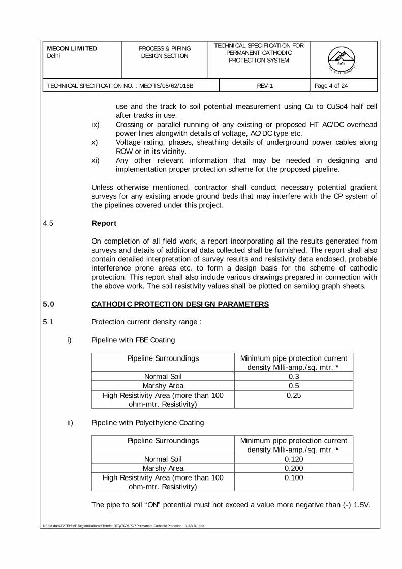
MECON LIMITEDDelhi
PROCESS & PIPINGDESIGN SECTION
TECHNICAL SPECIFICATION FORPERMANENT CATHODICPROTECTION SYSTEM
TECHNICAL SPECIFICATION NO. : MEC/TS/05/62/016B REV-1 Page 4 of 24
D:\old data\FATEH\MP Region\Kailaras\Tender RFQ\TCP&PCP\Permanent Cathodic Proection - 016B-R1.doc
use and the track to soil potential measurement using Cu to CuSo4 half cellafter tracks in use.
ix) Crossing or parallel running of any existing or proposed HT AC/DC overheadpower lines alongwith details of voltage, AC/DC type etc.
x) Voltage rating, phases, sheathing details of underground power cables alongROW or in its vicinity.
xi) Any other relevant information that may be needed in designing andimplementation proper protection scheme for the proposed pipeline.
Unless otherwise mentioned, contractor shall conduct necessary potential gradientsurveys for any existing anode ground beds that may interfere with the CP system ofthe pipelines covered under this project.
4.5 Report
On completion of all field work, a report incorporating all the results generated fromsurveys and details of additional data collected shall be furnished. The report shall alsocontain detailed interpretation of survey results and resistivity data enclosed, probableinterference prone areas etc. to form a design basis for the scheme of cathodicprotection. This report shall also include various drawings prepared in connection withthe above work. The soil resistivity values shall be plotted on semilog graph sheets.
5.0 CATHODIC PROTECTION DESIGN PARAMETERS
5.1 Protection current density range :
i) Pipeline with FBE Coating
Pipeline Surroundings Minimum pipe protection currentdensity Milli-amp./sq. mtr. *
Normal Soil 0.3Marshy Area 0.5
High Resistivity Area (more than 100ohm-mtr. Resistivity)
0.25
ii) Pipeline with Polyethylene Coating
Pipeline Surroundings Minimum pipe protection currentdensity Milli-amp./sq. mtr. *
Normal Soil 0.120Marshy Area 0.200
High Resistivity Area (more than 100ohm-mtr. Resistivity)
0.100
The pipe to soil “ON” potential must not exceed a value more negative than (-) 1.5V.
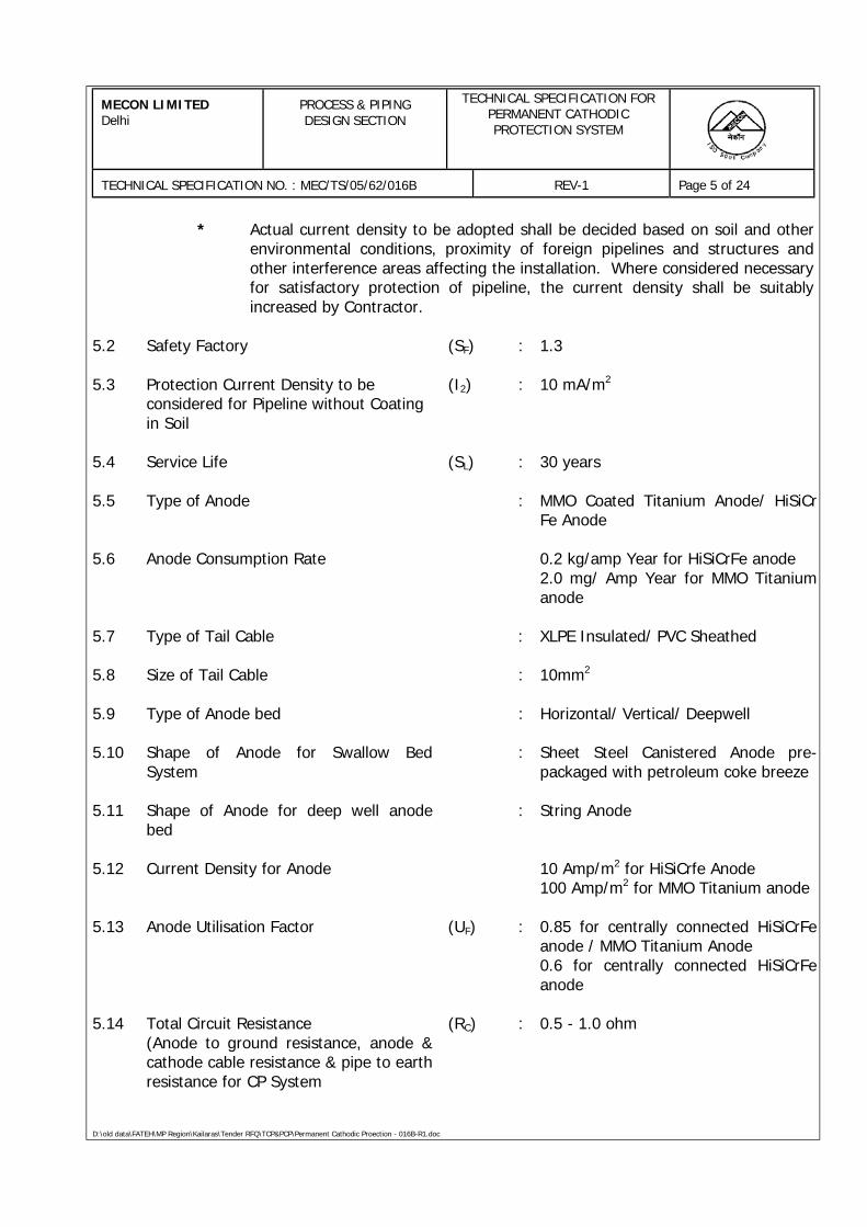
MECON LIMITEDDelhi
PROCESS & PIPINGDESIGN SECTION
TECHNICAL SPECIFICATION FORPERMANENT CATHODICPROTECTION SYSTEM
TECHNICAL SPECIFICATION NO. : MEC/TS/05/62/016B REV-1 Page 5 of 24
D:\old data\FATEH\MP Region\Kailaras\Tender RFQ\TCP&PCP\Permanent Cathodic Proection - 016B-R1.doc
* Actual current density to be adopted shall be decided based on soil and otherenvironmental conditions, proximity of foreign pipelines and structures andother interference areas affecting the installation. Where considered necessaryfor satisfactory protection of pipeline, the current density shall be suitablyincreased by Contractor.
5.2 Safety Factory (SF) : 1.3
5.3 Protection Current Density to beconsidered for Pipeline without Coatingin Soil
(I2) : 10 mA/m2
5.4 Service Life (SL) : 30 years
5.5 Type of Anode : MMO Coated Titanium Anode/ HiSiCrFe Anode
5.6 Anode Consumption Rate 0.2 kg/amp Year for HiSiCrFe anode2.0 mg/ Amp Year for MMO Titaniumanode
5.7 Type of Tail Cable : XLPE Insulated/ PVC Sheathed
5.8 Size of Tail Cable : 10mm2
5.9 Type of Anode bed : Horizontal/ Vertical/ Deepwell
5.10 Shape of Anode for Swallow BedSystem
: Sheet Steel Canistered Anode pre-packaged with petroleum coke breeze
5.11 Shape of Anode for deep well anodebed
: String Anode
5.12 Current Density for Anode 10 Amp/m2 for HiSiCrfe Anode100 Amp/m2 for MMO Titanium anode
5.13 Anode Utilisation Factor (UF) : 0.85 for centrally connected HiSiCrFeanode / MMO Titanium Anode0.6 for centrally connected HiSiCrFeanode
5.14 Total Circuit Resistance(Anode to ground resistance, anode &cathode cable resistance & pipe to earthresistance for CP System
(RC) : 0.5 - 1.0 ohm
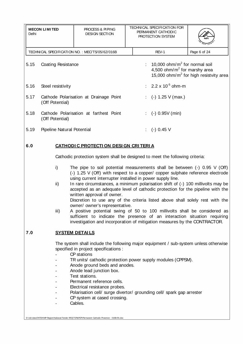
MECON LIMITEDDelhi
PROCESS & PIPINGDESIGN SECTION
TECHNICAL SPECIFICATION FORPERMANENT CATHODICPROTECTION SYSTEM
TECHNICAL SPECIFICATION NO. : MEC/TS/05/62/016B REV-1 Page 6 of 24
D:\old data\FATEH\MP Region\Kailaras\Tender RFQ\TCP&PCP\Permanent Cathodic Proection - 016B-R1.doc
5.15 Coating Resistance : 10,000 ohm/m2 for normal soil4,500 ohm/m2 for marshy area15,000 ohm/m2 for high resistvity area
5.16 Steel resistivity : 2.2 x 10⁻⁵ ohm-m
5.17 Cathode Polarisation at Drainage Point(Off Potential)
: (-) 1.25 V (max.)
5.18 Cathode Polarisation at farthest Point(Off Potential)
: (-) 0.95V (min)
5.19 Pipeline Natural Potential : (-) 0.45 V
6.0 CATHODIC PROTECTION DESIGN CRITERIA
Cathodic protection system shall be designed to meet the following criteria:
i) The pipe to soil potential measurements shall be between (-) 0.95 V (Off)(-) 1.25 V (Off) with respect to a copper/ copper sulphate reference electrodeusing current interrupter installed in power supply line.
ii) In rare circumstances, a minimum polarisation shift of (-) 100 millivolts may beaccepted as an adequate level of cathodic protection for the pipeline with thewritten approval of owner.Discretion to use any of the criteria listed above shall solely rest with theowner/ owner’s representative.
iii) A positive potential swing of 50 to 100 millivolts shall be considered assufficient to indicate the presence of an interaction situation requiringinvestigation and incorporation of mitigation measures by the CONTRACTOR.
7.0 SYSTEM DETAILS
The system shall include the following major equipment / sub-system unless otherwisespecified in project specifications :- CP stations- TR units/ cathodic protection power supply modules (CPPSM).- Anode ground beds and anodes.- Anode lead junction box.- Test stations.- Permanent reference cells.- Electrical resistance probes.- Polarisation cell/ surge divertor/ grounding cell/ spark gap arrester- CP system at cased crossing.- Cables.
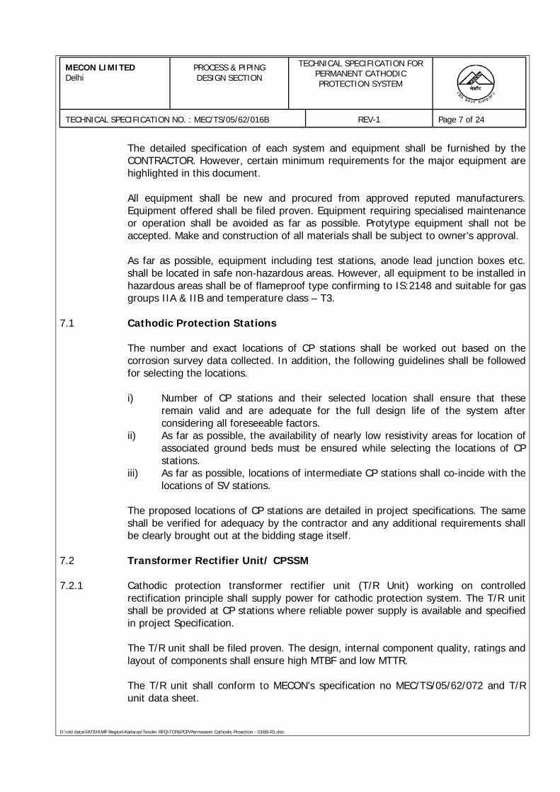
MECON LIMITEDDelhi
PROCESS & PIPINGDESIGN SECTION
TECHNICAL SPECIFICATION FORPERMANENT CATHODICPROTECTION SYSTEM
TECHNICAL SPECIFICATION NO. : MEC/TS/05/62/016B REV-1 Page 7 of 24
D:\old data\FATEH\MP Region\Kailaras\Tender RFQ\TCP&PCP\Permanent Cathodic Proection - 016B-R1.doc
The detailed specification of each system and equipment shall be furnished by theCONTRACTOR. However, certain minimum requirements for the major equipment arehighlighted in this document.
All equipment shall be new and procured from approved reputed manufacturers.Equipment offered shall be filed proven. Equipment requiring specialised maintenanceor operation shall be avoided as far as possible. Protytype equipment shall not beaccepted. Make and construction of all materials shall be subject to owner’s approval.
As far as possible, equipment including test stations, anode lead junction boxes etc.shall be located in safe non-hazardous areas. However, all equipment to be installed inhazardous areas shall be of flameproof type confirming to IS:2148 and suitable for gasgroups IIA & IIB and temperature class – T3.
7.1 Cathodic Protection Stations
The number and exact locations of CP stations shall be worked out based on thecorrosion survey data collected. In addition, the following guidelines shall be followedfor selecting the locations.
i) Number of CP stations and their selected location shall ensure that theseremain valid and are adequate for the full design life of the system afterconsidering all foreseeable factors.
ii) As far as possible, the availability of nearly low resistivity areas for location ofassociated ground beds must be ensured while selecting the locations of CPstations.
iii) As far as possible, locations of intermediate CP stations shall co-incide with thelocations of SV stations.
The proposed locations of CP stations are detailed in project specifications. The sameshall be verified for adequacy by the contractor and any additional requirements shallbe clearly brought out at the bidding stage itself.
7.2 Transformer Rectifier Unit/ CPSSM
7.2.1 Cathodic protection transformer rectifier unit (T/R Unit) working on controlledrectification principle shall supply power for cathodic protection system. The T/R unitshall be provided at CP stations where reliable power supply is available and specifiedin project Specification.
The T/R unit shall be filed proven. The design, internal component quality, ratings andlayout of components shall ensure high MTBF and low MTTR.
The T/R unit shall conform to MECON’s specification no MEC/TS/05/62/072 and T/Runit data sheet.
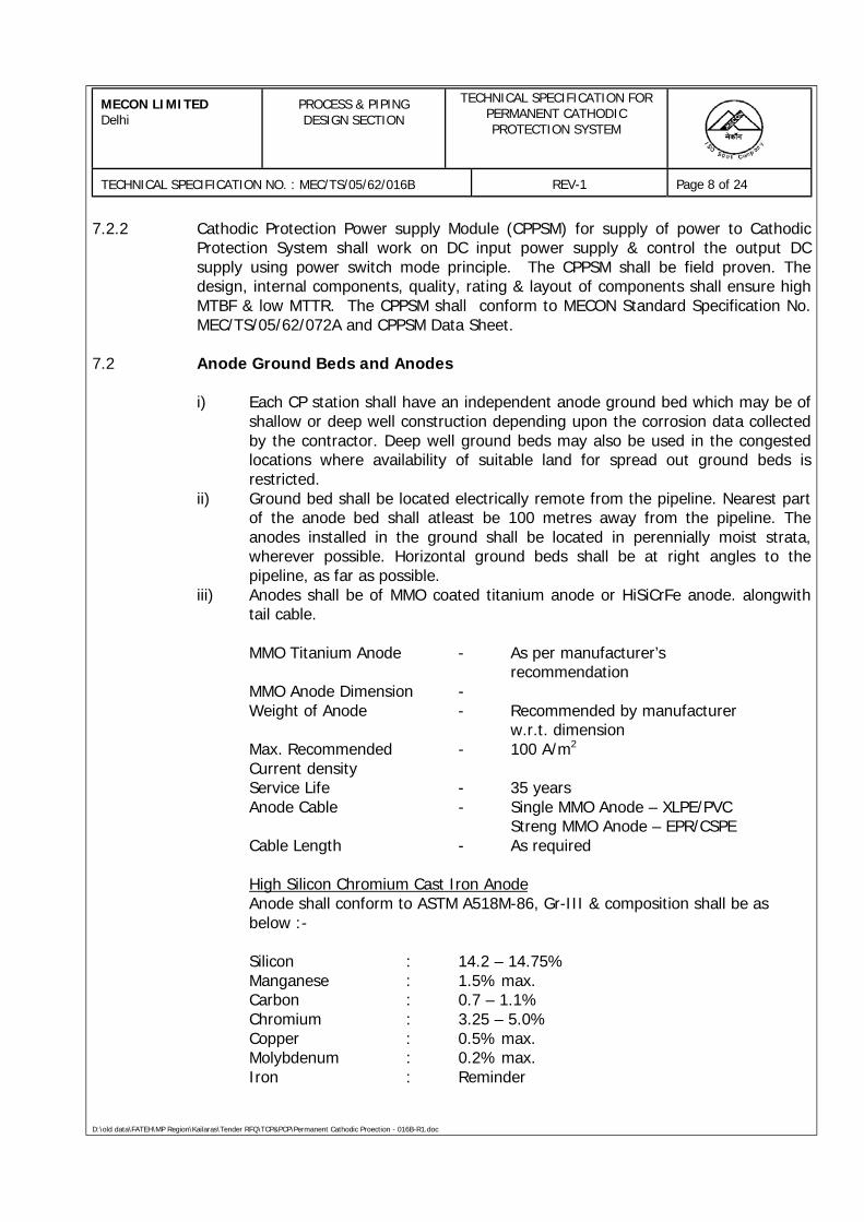
MECON LIMITEDDelhi
PROCESS & PIPINGDESIGN SECTION
TECHNICAL SPECIFICATION FORPERMANENT CATHODICPROTECTION SYSTEM
TECHNICAL SPECIFICATION NO. : MEC/TS/05/62/016B REV-1 Page 8 of 24
D:\old data\FATEH\MP Region\Kailaras\Tender RFQ\TCP&PCP\Permanent Cathodic Proection - 016B-R1.doc
7.2.2 Cathodic Protection Power supply Module (CPPSM) for supply of power to CathodicProtection System shall work on DC input power supply & control the output DCsupply using power switch mode principle. The CPPSM shall be field proven. Thedesign, internal components, quality, rating & layout of components shall ensure highMTBF & low MTTR. The CPPSM shall conform to MECON Standard Specification No.MEC/TS/05/62/072A and CPPSM Data Sheet.
7.2 Anode Ground Beds and Anodes
i) Each CP station shall have an independent anode ground bed which may be ofshallow or deep well construction depending upon the corrosion data collectedby the contractor. Deep well ground beds may also be used in the congestedlocations where availability of suitable land for spread out ground beds isrestricted.
ii) Ground bed shall be located electrically remote from the pipeline. Nearest partof the anode bed shall atleast be 100 metres away from the pipeline. Theanodes installed in the ground shall be located in perennially moist strata,wherever possible. Horizontal ground beds shall be at right angles to thepipeline, as far as possible.
iii) Anodes shall be of MMO coated titanium anode or HiSiCrFe anode. alongwithtail cable.
MMO Titanium Anode - As per manufacturer’srecommendation
MMO Anode Dimension -Weight of Anode - Recommended by manufacturer
w.r.t. dimensionMax. Recommended - 100 A/m2
Current densityService Life - 35 yearsAnode Cable - Single MMO Anode – XLPE/PVC
Streng MMO Anode – EPR/CSPECable Length - As required
High Silicon Chromium Cast Iron AnodeAnode shall conform to ASTM A518M-86, Gr-III & composition shall be asbelow :-
Silicon : 14.2 – 14.75%Manganese : 1.5% max.Carbon : 0.7 – 1.1%Chromium : 3.25 – 5.0%Copper : 0.5% max.Molybdenum : 0.2% max.Iron : Reminder
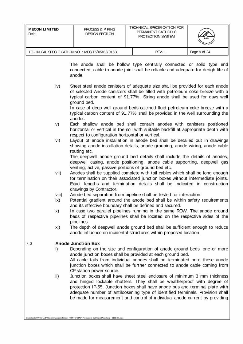
MECON LIMITEDDelhi
PROCESS & PIPINGDESIGN SECTION
TECHNICAL SPECIFICATION FORPERMANENT CATHODICPROTECTION SYSTEM
TECHNICAL SPECIFICATION NO. : MEC/TS/05/62/016B REV-1 Page 9 of 24
D:\old data\FATEH\MP Region\Kailaras\Tender RFQ\TCP&PCP\Permanent Cathodic Proection - 016B-R1.doc
The anode shall be hollow type centrally connected or solid type endconnected, cable to anode joint shall be reliable and adequate for derigh life ofanode.
iv) Sheet steel anode canisters of adequate size shall be provided for each anodeof selected Anode canisters shall be filled with petroleum coke breeze with atypical carbon content of 91.77%. String anode shall be used for days wellground bed.In case of deep well ground beds calcined fluid petroleum coke breeze with atypical carbon content of 91.77% shall be provided in the well surrounding theanodes.
v) Each shallow anode bed shall contain anodes with canisters positionedhorizontal or vertical in the soil with suitable backfill at appropriate depth withrespect to configuration horizontal or vertical.
vi) Layout of anode installation in anode bed shall be detailed out in drawingsshowing anode installation details, anode grouping, anode wiring, anode cablerouting etc.The deepwell anode ground bed details shall include the details of anodes,deepwell casing, anode positioning, anode cable supporting, deepwell gasventing, active, passive portions of ground bed etc.
vii) Anodes shall be supplied complete with tail cables which shall be long enoughfor termination on their associated junction boxes without intermediate joints.Exact lengths and termination details shall be indicated in constructiondrawings by Contractor.
viii) Anode bed separation from pipeline shall be tested for interaction.ix) Potential gradient around the anode bed shall be within safety requirements
and its effective boundary shall be defined and secured.x) In case two parallel pipelines running in the same ROW. The anode ground
beds of respective pipelines shall be located on the respective sides of thepipelines.
xi) The depth of deepwell anode ground bed shall be sufficient enough to reduceanode influence on incidental structures within proposed location.
7.3 Anode Junction Boxi) Depending on the size and configuration of anode ground beds, one or more
anode junction boxes shall be provided at each ground bed.All cable tails from individual anodes shall be terminated onto these anodejunction boxes which shall be further connected to anode cable coming fromCP station power source.
ii) Junction boxes shall have sheet steel enclosure of minimum 3 mm thicknessand hinged lockable shutters. They shall be weatherproof with degree ofprotection IP-55. Junction boxes shall have anode bus and terminal plate withadequate number of antiloosening type of identified terminals. Provision shallbe made for measurement and control of individual anode current by providing
MECON LIMITEDDelhi
PROCESS & PIPINGDESIGN SECTION
TECHNICAL SPECIFICATION FORPERMANENT CATHODICPROTECTION SYSTEM
TECHNICAL SPECIFICATION NO. : MEC/TS/05/62/016B REV-1 Page 10 of 24
D:\old data\FATEH\MP Region\Kailaras\Tender RFQ\TCP&PCP\Permanent Cathodic Proection - 016B-R1.doc
suitable shunt and resistors. Anode disconnecting link shall be provided foreach anode circuit. 30% spare terminals shall be provided.
iii) In case of sectionalized ground beds, an additional common anodedisconnecting link for each section of ground bed shall be provided fordisconnection of any section of ground bed.
7.5 Cathode Junction Box
One cathode junction box shall be provided at each CP Station for Permanent Pipe tosoil potential measurement circuit & cathode connection. Junction boxes shall havesheet steel enclosure of minimum 3 mm thickness and hinged lockable shutters. Theyshall be weatherproof with degree of protection IP-55. Junction boxes shall havecathode bus and terminal plate with adequate number of antiloosening type ofidentified terminals.
7.4 Test Stationsi) Test stations shall be provided along the pipeline ROW for monitoring the
performance of the cathodic protection system at intervals not exceeding 1000meters. In addition to above, test stations shall also be provided at thefollowing locations :-a) At both sides of major road crossings.b) At all insulating joints.c) At vulnerable locations with drastic changes in soil resistivity.d) At locations of grounding cells, surge diverters and polarisation cells.e) At HT AC/DC overhead line crossings selected locations where HT
overhead is in the vicinity of the pipeline.f) At railway line crossings and along running parallel to the pipeline.g) At both sides of major river crossings.h) At high voltage cable crossing or along routes where HV cables are
running in parallel.i) In the vicinity of DC network or grounding systems where interference
problems are suspected.j) At crossings of other pipelines/ structures.k) At the locations of reference cell and ER probe installation.l) At both sides of cased crossings.m) Locations where interference is expected.n) At any other locations considered necessary by OWNER/ OWNER’S
representative.
ii) Bond stations shall be provided at required locations as a means to monitorand control current flow between the pipeline and foreign pipelines / structuresthat may exist in common ROW.
iii) Test stations with current measuring facility shall be provided at interval notexceeding 3.0 KM, at each intermediate CP station drainage point (to measurepipeline current on any one side of pipeline from drainage point), at
MECON LIMITEDDelhi
PROCESS & PIPINGDESIGN SECTION
TECHNICAL SPECIFICATION FORPERMANENT CATHODICPROTECTION SYSTEM
TECHNICAL SPECIFICATION NO. : MEC/TS/05/62/016B REV-1 Page 11 of 24
D:\old data\FATEH\MP Region\Kailaras\Tender RFQ\TCP&PCP\Permanent Cathodic Proection - 016B-R1.doc
interference prone areas, on both sides of major river crossings and at least attwo additional locations along the pipeline ROW between two CP stations.
iv) All test stations shall have weatherproof enclosure, with hinged lockableshutter and degree of protection IP-55. Enclosure shall be made of sheet steelof atleast 3 mm thickness and shall be suitable for MS post mounting.
v) Test station shall be installed with the face of the test station facing thepipeline. The nameplate of test stations shall carry the following minimuminformation :- Test station number- Chainage in Km.- Test station connection scheme- Distance from pipe line in mtrs.- Direction of product flow.
vi) Number of terminals and different schemes of wiring shall be as per the teststation connection scheme sketch. Minimum twenty percent spare terminalsshall be provided in each test station.
vii) The location of all the test station shall be marked with their connectionscheme and other relevant information on alignment sheets. A detailed test-station schedules shall be prepared.
7.5 Permanent Reference Cellsi) High purity copper / copper sulphate reference cells with proven high reliability
shall be provided for stable pipe to soil potential measurement reference at CPstations and at computerized test station locations along ROW.
ii) Three numbers reference electrodes shall be installed at each cathodicprotection station.iv) The reference cell for high resistivity areas shall be suitable for the prevailing
dry soil conditions to give maximum service life.v) Permanent reference cells shall be installed with backfill material.vi) Silver/ Silver Chloride reference cells in place of copper / copper sulphate cells
shall be provided at marshy area locations where water table is high and sub-soil water or soil shows chlorine concentration more than 300 PPM.
vii) The cable from reference cells shall be provided upto CP power source at CPstations. The cable shall be routed through cathod junction box near pipeline.
viii) The life of reference cell shall be minimum 20 years under installed condition.
7.6 Electrical Resistance Probe
Where specified in project specifications, electrical resistance probes utilising theelectrical resistance technique shall be provided along the pipeline at marshy areasand at vulnerable locations to monitor the external corrosion activity on the pipeline.The lead wires of the probe shall be connected to pipeline and terminated inside test
MECON LIMITEDDelhi
PROCESS & PIPINGDESIGN SECTION
TECHNICAL SPECIFICATION FORPERMANENT CATHODICPROTECTION SYSTEM
TECHNICAL SPECIFICATION NO. : MEC/TS/05/62/016B REV-1 Page 12 of 24
D:\old data\FATEH\MP Region\Kailaras\Tender RFQ\TCP&PCP\Permanent Cathodic Proection - 016B-R1.doc
station enabling periodic resistance measurement with the probe using a portablemeasuring instrument.
The material of the E/R probe element shall be of the same alloy as of the pipelinematerial.
The E/R probes shall be provided preferably at the bottom portion of pipeline. Thelocations of E/R probes shall be got approved.
Portable E/R probe reading instrument shall be supplied by contractor.
7.7 Polarisation Cell and Surge Divertor / Grounding Cell
i) Where high voltage (66 KV and above) transmission line runs in parallel orcrosses the pipeline, the pipeline shall be grounded through polarisation cells &zinc anodes of minimum 20 kg net each. Alternatively, grounding could bedone directly with zinc galvanic anodes of minimum 20 kg net each at thediscretion of owner. Grounding shall be done at regular intervals wheretransmission lines run parallel within 25 meter of the pipeline to ground anysurges on the pipeline that would appear in case of transmission line faults.
ii) In case of continuous induction of voltage on the pipeline beyond safe limits isexpected or observed during commissioning due to HV Line of any rating orothers equipment., the pipeline shall be grounded to the earth system ofnearest HV transmission tower of the transmisison line causing the voltageinduction through polarisation cell or the pipeline shall be grounded to aseparate earthing system of zinc galvanic anodes through polarisation cell.Alternatively, the pipeline shall be directly grounded with zinc galvanic anodesof minimum 20 kg net each at the discretion of the owner. The polarisation cellshall be installed in test station.
iii) Spark gap arrestor alongwith zinc ground cell shall be connected across eachinsulating joint to protect in from high voltage surges.
iv) Alternatively, zinc grounding cell may be provided across insulating joints alongROW where the pipeline on both the sides of the insulating joint arecathodically protected and difference of protection voltage is not more then 0.4volts.
v) The total system including cables, cable termination, anodes/ surge divertorsshall be suitable for the anticipated fault current at the location of installation.
vi) Unless otherwise specified on data sheet, the minimum rating of groundingcells, polarisation cells and surge diverters shall be as below:
a) Grounding Cell
- Type : Zinc, 2 or 4 plate type.- Current rating : Suitable to pass more than 10KA surge b) Polarisation cell
MECON LIMITEDDelhi
PROCESS & PIPINGDESIGN SECTION
TECHNICAL SPECIFICATION FORPERMANENT CATHODICPROTECTION SYSTEM
TECHNICAL SPECIFICATION NO. : MEC/TS/05/62/016B REV-1 Page 13 of 24
D:\old data\FATEH\MP Region\Kailaras\Tender RFQ\TCP&PCP\Permanent Cathodic Proection - 016B-R1.doc
Type:- Solid station Electrolytic tie multi pairs S.S plate grounding cell.
c) Spark Gap Arrester
- Type : Spark gap.- Current, 8/20 : 100 Kilo Amp.
micro second wave- Spark- over, AC Voltage- 50 Hz : 1 KV- Impulse (1.2/50 : 2.2 KV
micro sec)
vii) The grounding cell, spark gaparrester and polarisation cell system shall beadequately sized and suitable for the design life of permanent CP system. Thedirectly buried zinc or magnesium anodes shall also be adequately sized for thelife of the permanent CP system, taking into consideration discharge from theanodes. The grounding system shall have minimum resistance to earth torestrict the pipeline voltage as per NACE Criteria.
viii) HT transmission overhead lines of voltage below 66KV also required mitigationmeasures should be provided to take care of continuous induction of voltageinterface due to presence of transmission line in close proximity.
7.8 CP at cased crossing
i) At cased crossing where casing is coated, the casing shall be protected bysacrificial anode installations which shall be provided at both ends of casing.The anode installation shall be sized based on the permanent C.P. designparameters and design life specified for the main pipeline but where casing isuncoated additional protection for casing is not required.
The carrier pipe inside the casing shall be protected by zinc ribbon anodes weldconnected to the outer surface of bottom of carrier pipe extending upto hourhand position of 4 and 8 o’clock. The anodes shall be placed at close intervalsas per design calculations and shall be sized based on the permanent CPdesign parameters and design life.
7.9 Painting
The sheet steel used for fabrication shall be thoroughly cleaned and degreased toremove mill scale, rust, grease and dirt. Fabricated structures shall be pickled and thenrinsed to remove any trace of acid. The under surface shall be prepared by applying acoat of phosphate paint and a coat of yellow zinc chromate primer. The under surfaceshall be free from all imperfections before undertaking the finishing coat.
MECON LIMITEDDelhi
PROCESS & PIPINGDESIGN SECTION
TECHNICAL SPECIFICATION FORPERMANENT CATHODICPROTECTION SYSTEM
TECHNICAL SPECIFICATION NO. : MEC/TS/05/62/016B REV-1 Page 14 of 24
D:\old data\FATEH\MP Region\Kailaras\Tender RFQ\TCP&PCP\Permanent Cathodic Proection - 016B-R1.doc
After preparation of the under surface, spray painting with two coats of final paintshall be done. The finished panels shall be dried in ovens in dust free atmosphere.Panel finish shall be free from imperfections like pinholes, orange peels, runoff paintetc. Bidder shall furnish detailed painting procedure alongwith bids.
All unpainted steel parts shall be cadmium plated to prevent rust formation.
7.10 Cables
i) Cables shall be annealed high conductivity tinned stranded copper conductor,XLPE insulated, PVC sheathed, 650/1100 V grade, armoured forCathode/Anode / measurement cable. Unless otherwise specified in projectspecifications, the size of the copper conductor shall be minimum 35 sq. mm.for anode and cathode cables, 6 sq. mm. for potential measurement andreference cells, 10 sq. mm. for current measurement, 25 sq. mm. for bonding/grounding and 10 sq. mm. for anode tail cables. The anode tail cables shall beXLPE insulated & PVC sheathed and not be armoured and length shall besufficient for termination on anode lead junction box without any joint. PEsleeves shall be provided for unarmoured cables.
ii) The T/R unit incomer cable shall be minimum 10 sq. mm. aluminium, 650/1100V PVC insulated, armoured, PVC sheathed.
7.11 Panel Cabling and cable glands
Adequate space shall be provided inside the panel for termination of cables.Termination shall be performed using crimped lugs. Tags with cable numbersengraved on it shall be attached to each cable at both ends. Cable glands shall bedouble compression type of Nickel/ Chromium plated brass. The lugs shall be of tinnedcopper. Phases of AC power cables shall be identified with red, yellow, blue PVCadhesive material.
The armour of the cables from pipeline to CP station (potential measurement,reference cell & drainage cables etc.), CP station to ground bed (anode cable) and teststation to pipeline shall be earthed only at one end of the cable to avoid armourcarrying CP current.
8.0 INSTALLATION
8.1 Cable Laying
j) Cables shall be laid in accordance with approved layout drawings to beprepared by the contractor. No straight through joint shall be permitted in asingle run of cable. Cable route shall be carefully measured and cables cut torequired length. Enough slackness in cable shall be provided near anodes toaccount for any settling of anode.
MECON LIMITEDDelhi
PROCESS & PIPINGDESIGN SECTION
TECHNICAL SPECIFICATION FORPERMANENT CATHODICPROTECTION SYSTEM
TECHNICAL SPECIFICATION NO. : MEC/TS/05/62/016B REV-1 Page 15 of 24
D:\old data\FATEH\MP Region\Kailaras\Tender RFQ\TCP&PCP\Permanent Cathodic Proection - 016B-R1.doc
ii) All cables inside station / plant area shall be laid at a depth of 0.75 M. Cablesoutside station / plant area shall be laid at a depth of 1.5m. Cables shall be laidin sand under brick cover and back filled with normal soil. Outside station /plant area, the routes shall be marked with polythylene cable warning matsplaced at a depth of 0.9 mtr. from the finished grade.
iii) In case of above ground cable installations, all un-armoured CP cables shall belaid in GI conduits of sufficiently large size.
iv) All underground unarmoured cables shall run through PE sleeves. Distantmeasurement cables and permanent reference cell cables routed along thepipeline shall be carried at the top of the carrier pipe by securely strapping itwith adhesive tape or equivalent as required.
v) RCC or GI pipes of proper size shall be provided for all underground cables forroad crossings.
vi) Cables shall be neatly arranged in trenches in such a manner that criss-crossing is avoided and final take-off to equipment is facilitated.
8.2 Cable to pipe connections
All cable connections to the pipeline including charged foreign pipelines shall be madeby an approved exothermic process. A suitable water proof sealing system of the cableconnections shall be made which will be compatible with parent coating system of thepipeline after exnothernice process.
For charged pipeline pin-brazing shall be used. Eutectic solder shall not be acceptablefor charged or non-charged pipeline.
8.3 Ground bed fencing
A chain link fencing shall be provided around each ground bed location as per jobrequirements.
8.4 Civil Works
All civil works as per enclosed specifications associated with the complete cathodicprotection system are included in scope of contractor. This shall include providingcable trenches and foundations for all equipment, outdoor T/R units, anode leadjunction boxes, all test stations, polarisation cells, etc.
9.0 SHOP INSPECTION AND TESTING
i) Owner/ Owner’s representative shall visit the works during manufacture ofvarious equipment to assess the progress of work as well as to ascertain thatonly quality raw materials are used. All necessary assistance shall be providedby contractor and vendors during such inspections.
MECON LIMITEDDelhi
PROCESS & PIPINGDESIGN SECTION
TECHNICAL SPECIFICATION FORPERMANENT CATHODICPROTECTION SYSTEM
TECHNICAL SPECIFICATION NO. : MEC/TS/05/62/016B REV-1 Page 16 of 24
D:\old data\FATEH\MP Region\Kailaras\Tender RFQ\TCP&PCP\Permanent Cathodic Proection - 016B-R1.doc
ii) The minimum testing, inspection requirements for all components / equipmentshall conform to requirement as defined in the relevant codes and standards.Detailed inspection and testing procedures alongwith the acceptance criteriashall be prepared by contractor for Owner’s approval.
iii) Test certificates including test records, performance curves etc. shall befurnished with sufficient information to identify the equipment to which thecertificate referes and must carry project title, owner’s name and purchaseorder details etc.
iv) Owner reserves the right to ask for inspection of all or any item 7under thecontract and witness all tests and carryout inspection or authorise hisrepresentative to witness tests and carryout inspection. Contractor shall notifythe Owner/ Owner’s representative atleast 20 days in advance giving exactdetails of tests, dates and addresses of locations where the tests would becarried out.
10.0 PACKING AND TRANSPORT
All equipment / material shall be protected for inland/marine, transport, carriage atsite and outdoor storage during transit and at site. All packages shall be clearly, legiblyand durably marked with uniform block letters giving the relevant equipment /material details. Each package shall contain a packing list in a water proof envelope.Copies of the packing list, in triplicate, shall be forwarded to owner prior to despatch.All items of material shall be clearly marked for easy identification against the packinglist.
11.0 FIELD TESTING AND COMMISSIONING
11.1 System Testing at Site
The contractor shall furnish the detailed field testing and commissioning proceduresfor approval. Field tests as per these approved procedures shall be carried out on theequipment / systems before these are put into service. Acceptance of the completeinstallation shall be contingent upon inspection and test results. Field testing shallinclude but not be limited to the following.
i) Contractor shall carryout pre-commissioning operation after completion ofinstallation of the system including all pre-commissioning checks, setting of allequipment, control and protective devices. All site tests, reliability andperformances tests shall be carried out by contractor.
ii) Before the electrical facilities are put into operation, necessary tests shall becarried out to establish that all equipment, devices, wiring and connection havebeen correctly installed, connected and are in good working condition asrequired for the intended operation.
iii) Owner/ Owner’s representative may witness all tests. At least one week’snotice shall be given before commencing the tests.
MECON LIMITEDDelhi
PROCESS & PIPINGDESIGN SECTION
TECHNICAL SPECIFICATION FORPERMANENT CATHODICPROTECTION SYSTEM
TECHNICAL SPECIFICATION NO. : MEC/TS/05/62/016B REV-1 Page 17 of 24
D:\old data\FATEH\MP Region\Kailaras\Tender RFQ\TCP&PCP\Permanent Cathodic Proection - 016B-R1.doc
iv) All tools, equipment and instruments required for testing shall be provided bycontractor.
v) Generally, the following minimum tests must be carried out and recorded inproformas given in subsequent clauses :
Checking : Visual inspection, comparison with drawings and specifications.
Inspection : Detailed physical inspection, if necessary, by taking apartthe component parts.
Testing : Simulation tests of equipment to determine itsoperational fitness.
a) Cables- Cable no.- Voltage grade.- Conductor cross section- Continuity check- Voltage test- Insulation resistance values between each core & earth, between cores.
All cables shall be tested by 500V megger.
b) E/R Probe- Location / Identification number- Checking of wiring as per schematics- Resistance reading of probe
c) Reference Cell- Location- Potential reading- Type of cell
d) Insulating JointInsulation resistance across the joint shall be checked before and aftercharging the pipeline by means of insulating joint tester. Pipe to soil potentialof both protected and non-protected sides of the insulating joint shall bechecked before and after energisation of CP system.
e) Surge Diverter- Location / identification number- Rating- Check for healthyness
MECON LIMITEDDelhi
PROCESS & PIPINGDESIGN SECTION
TECHNICAL SPECIFICATION FORPERMANENT CATHODICPROTECTION SYSTEM
TECHNICAL SPECIFICATION NO. : MEC/TS/05/62/016B REV-1 Page 18 of 24
D:\old data\FATEH\MP Region\Kailaras\Tender RFQ\TCP&PCP\Permanent Cathodic Proection - 016B-R1.doc
f) Polarisation Cell- Location / Identification number- Rating- Check for electrolyte- Check for wiring- Check standby current drain after CP system energisation. (Current drain with
respect to voltage across the cell shall be recorded).- Details of grounding provided for the polarisation cell.
g) Spark Gap Arrester- Location/ identification NO- Ratings- Check for healthiness
h) Anode Ground Bed- Location / Station- Check for actual layout and compliance with drawings- Resistance of each individual anode- Current dissipation by each individual anode with respect to anode voltage- Total resistance of complete anode bed- Mutual interference
i) Grounding Cell- Location- Type / no. of anodes- Ratings
11.2 CP Commissioning Procedure
A model commissioning procedure for a 2 station CP system of a pipeline is givenbelow for general guidance. Contractor shall develop detailed commissioningprocedure as per this guideline and get it approved before commencing CP systemcommissioning activities.
i) On completion of installation of anode beds and other systems as envisaged inthis specification, they shall be individually checked, tested and comparedagainst the agreed specifications and procedure.
ii) The CP commissioning shall be carried out with current interrupter provided inthe output of the CP TR/ ECU Unit to measure CP “ON” & “OFF” potentials.
iii) Current dissipated by each anode shall be corrected through anode leadjunction box.
iv) Electrical continuity of the entire pipeline shall be verified in conformity withdesign.
v) Input resistance of the pipeline at all the drainage points shall be checked andrecorded.
MECON LIMITEDDelhi
PROCESS & PIPINGDESIGN SECTION
TECHNICAL SPECIFICATION FORPERMANENT CATHODICPROTECTION SYSTEM
TECHNICAL SPECIFICATION NO. : MEC/TS/05/62/016B REV-1 Page 19 of 24
D:\old data\FATEH\MP Region\Kailaras\Tender RFQ\TCP&PCP\Permanent Cathodic Proection - 016B-R1.doc
vi) All current measuring test stations shall be calibrated and recorded.vii) Temporary protection facilities provided (if any) which do not form part of
permanent CP shall be disconnected from the system & removed unless agreedotherwise.
viii) The pipeline shall be allowed to depolarize for atleast 72 hours after switching‘off’ the protection (if any) of all other pipelines in the common R.O.W.
ix) Before the pipeline are put on charge by switching ‘on’ any of the CP stations,natural structure-to-electrolyte potential values at all the test stations of thesystem shall be measured with respect to Copper/ Copper Sulphate half cell.
x) CP station no. 1 shall be energised so as to achieve a maximum pipe soilpotential (PSP) as specified at the test station nearest to the drainage point,and observations on either spread of protected portion of pipeline under thisCP station shall be taken for PSP values pipeline current values across thecross section of the pipeline shall also be determined at all the intended teststations influenced by this station.
xi) CP station no. 1 shall now be switched ‘off’’ and CP station no. 2 shall beswitched ‘on’ and measurement procedure as adopted in above step (at cl. IX)shall be repeated.
xii) All the CP stations of the system shall be switched ‘off’ and the pipelines shallbe allowed to depolarize. All the CP stations in the system shall then besimultaneously switched 'on' and PSP values at the drainage points of pipelineshall be brought to a value of maximum PSP as specified, and a complete setof PSP observations shall be taken.
Another complete set of PSP observations shall be taken after lines havestayed on charge for 24/ 48 hours. If there are appreciable differences in theseobservations as compared to those of earlier set, a third set of observationsshall be taken after 72 hrs. Maximum drainage point protective potentials shallnot be allowed to go beyond the maximum PSP values as specified, in anycase.
The output of all CP stations shall then be so adjusted that the sites ofoccurrence of least negative protective potentials are increased to (-) 1.00 V. Afull set of observations shall again be taken 72 hrs. after the adjustment ofpotentials and the protection system shall be left in this state of operation.
xiii) Care shall be exercised to ensure that power supply remains uninterruptedduring the period of commissioning. In case of an interruption, the test inprogress shall be repeated after allowing time for polarization. More sets ofobservations may be advised to be taken by the Owner/ Owner'srepresentative in any of the above mentioned steps.
xiv) PSP values at each of the test stations of the existing pipelines shall bemeasured and plotted where existing pipelines run in parallel to the newpipeline and mutual interference situations between the pipelines shall beidentified and necessary mitigation shall be carried out.

MECON LIMITEDDelhi
PROCESS & PIPINGDESIGN SECTION
TECHNICAL SPECIFICATION FORPERMANENT CATHODICPROTECTION SYSTEM
TECHNICAL SPECIFICATION NO. : MEC/TS/05/62/016B REV-1 Page 20 of 24
D:\old data\FATEH\MP Region\Kailaras\Tender RFQ\TCP&PCP\Permanent Cathodic Proection - 016B-R1.doc
Interference situations shall also be identified and mitigated by comparingdifferent sets of readings taken at same test stations at different intervals oftime under identical conditions where positive potential swing exceed 50 mV.
xv) Final records of testing and commissioning including graphical representationof final structure to electrolyte potential readings shall be compiled withinterpretation in consolation with owner/ owner's representative andsubmitted.
xvi) As a result of these tests, if any deficiencies are found in the system, the sameshall be rectified by the contractor at no extra cost or time effect, to thecomplete satisfaction of Owner/ Owner's representative. Such deficiencies shallinclude mitigation of interference problems that may be found existing in thecourse of testing and commissioning. A set of PSP observations shall also betaken during the peak of the first dry season after commissioning the systeminto regular operation. Any deficiency found in the protection of the pipelineshall have to be rectified by the contractor at his own cost.
xvii) If it is found during commissioning that the sites of occurrence of leastnegative protective potentials are less negative than (-) 1.00 V even after 72hrs. of operation, then the drainage point potentials shall be increaseddepending upon anode ground bed currents in consolation with Owner/Owner's representative In any case, the drainage point protective 'ON'potential values shall not exceed the PSP values specified at cl. 5.1 of thisdocument and the pipe to soil 'OFF' potential shall not exceed a value morenegative than (-) 1.20 V at any location on the pipeline.
xviii) The current dissipated by individual anodes shall be measured from the anodelead junction box and corrected for equal dissipation to the extent possiblekeeping the total ground bed current same.
12.0 INTERFERENCE MITIGATION
12.1 Investigation shall be made for stray current electrolysis of the pipeline, mutualinterference between the pipeline and foreign pipelines / structures, interference onforeign pipelines / structures due to the CP of the pipeline and ground bed,interference on metallic structures which lie in between pipeline and ground bed ornear to ground bed, AC induction on pipeline due to overhead high voltage powerlines, interference due to high voltage DC lines, electric traction etc.
12.2 Measurements including pipe to soil potentials and pipe currents etc. on the pipeline /structure being CP protected and on foreign pipelines / structures, and groundpotential gradient etc. shall be made to investigate the current discharge and pickuplocations. In case of fluctuating stray currents, investigations shall be madecontinuously over a period of time and if required simultaneously at different locationsto find out the stray current source (s). Recorders shall be preferably be used for longtime measurements.
MECON LIMITEDDelhi
PROCESS & PIPINGDESIGN SECTION
TECHNICAL SPECIFICATION FORPERMANENT CATHODICPROTECTION SYSTEM
TECHNICAL SPECIFICATION NO. : MEC/TS/05/62/016B REV-1 Page 21 of 24
D:\old data\FATEH\MP Region\Kailaras\Tender RFQ\TCP&PCP\Permanent Cathodic Proection - 016B-R1.doc
12.3 Wherever foreign pipelines which may or may not be protected by an independent CPsystem run in parallel to the protected pipeline, either in the same trench or very nearto the protected pipeline and are not bonded to it, investigations shall be performedfor current discharge points on both the pipelines.
12.4 Mitigative measures shall be provided depending upon the type of interference. Theseshall include installation of bond with variable resistor and diodes, installation ofgalvanic anodes for auxiliary drainage of current, adjustment/ relocation (if possible)of offending interference source, provision of electrical shield etc. depending on thetype of interference.
Bond with foreign pipelines / structures as a mitigation measure shall be providedwhere the owners of the foreign pipelines / structures have no objection. Otherwisealternative mitigatio measures shall be provided. Wherever bonding is provided formitigaiton, the bonding resistor shall be adjusted for optimum value for minimum / nointerference. Galvanic anodes installed as a mitigaiton measure shall be adequatelysized for the design life specified for permanent CP system.
12.5 Where high voltage (66 KV and above) transmission lines run in parallel or cross thepipeline, the pipeline shall be grounded through polarisation cells at regular intervalsto ground any surge on the pipeline that would appear in case of transmission linefaults. Alternatively, grounding could also be done with galvanic anodes (Magnesiumor Zinc depending on pipeline voltage) at the discretion of the owner. These groundinginstallation shall be provided wherever transmission lines run within 25 mtr. of thepipeline.
A.C. voltage measurements shall also be made on the pipeline to find out continuousinduction of voltage beyond safe limits. In such a case, the pipeline shall be groundedto ht enearest transmission galvanic (zinc or magnesium) anodes at the discretion ofthe owner.
13.0 CLOSE INTERVAL POTENTIAL SURVEY
Where specified, contractor shall carry out a close internal potential survey over theentire length of pipeline by computerised potential logging method and identifysuspected holiday spots on the pipeline coating, after the back filling has beenconsolidated sufficiently and CP system has stabilized. Contractor shall identify thenecessary pipe coating required to be repaired. Detailed procedures for running thissurvey shall be submitted for approval.
The close interval potential logging survey shall be carried out at approx. 0.75mintervals & both “ON & “OFF” potentials shall be measured by operating the currentinterrupters of CP TR/ ECU unit during survey
MECON LIMITEDDelhi
PROCESS & PIPINGDESIGN SECTION
TECHNICAL SPECIFICATION FORPERMANENT CATHODICPROTECTION SYSTEM
TECHNICAL SPECIFICATION NO. : MEC/TS/05/62/016B REV-1 Page 22 of 24
D:\old data\FATEH\MP Region\Kailaras\Tender RFQ\TCP&PCP\Permanent Cathodic Proection - 016B-R1.doc
14.0 DRAWINGS AND DOCUMENTS
14.1 General
i) Within three weeks from the date of issue of Purchase Order, Contractor shallsubmit four copies of the list of all drawings / data/ manuals / procedures to besubmitted for approval, identifying each document by a number anddescriptive title and schedule date. This list shall be revised and extended, asnecessary, during the progress of work.
ii) All drawings and documents shall be in English and shall follow metric system.Number of copies for each submission shall be as follows unless specifiedotherwise :
Submission No. of copies
a) For Review/ Approval 6 copies
b) Drawings issued for 6 copiesexecution / construction
c) Final / As-built drgs. 6 copes and one set of reproducible.
d) Operation / Maintenance 6 copiesManual, Vendor data
14.2 Contract Drawings and Documents
As a part of the contract, drawings and documents to be furnished by the contractorshall include but are not limited to the following :
i) Report on corrosion survey.ii) Basis of system design and design calculations, equipment selection criteria
and sizing calculations.iii) Bills of material, material requisitions and Purchase requisitions.iv) Detailed construction drawings (including as-built status).
a) Separate layout drawings for each CP station showing anode- ground bedlocation, anode- ground bed installation details, CP station location, cablelaying, ROW location. Drainage connection location, permanent reference celllocations and topographic details of the entire area.
b) Equipment layout, cable layout and schedules.
MECON LIMITEDDelhi
PROCESS & PIPINGDESIGN SECTION
TECHNICAL SPECIFICATION FORPERMANENT CATHODICPROTECTION SYSTEM
TECHNICAL SPECIFICATION NO. : MEC/TS/05/62/016B REV-1 Page 23 of 24
D:\old data\FATEH\MP Region\Kailaras\Tender RFQ\TCP&PCP\Permanent Cathodic Proection - 016B-R1.doc
c) Marker drawings for cable route, anode-ground bed, drainage connectionpoint, permanent reference cell, E/R probe, polarisation cell, pipeline groundinganodes, grounding cells, etc.
d) Fabrication details of High Silicon cast iron canistered anode with tail cable.e) Fabrication, connection and installation drawing for anode-junction box.f) Anode- ground bed construction and installation details for horizontal anode-
ground bed and deep well ground bed.g) Fabrication, installation and connection scheme drawing for different types of
test-stations.h) Fabrication and installation details of Copper/ Copper Sulphate type, Silver/
Silver Chloride type and Zinc type permanent reference cells, E/R probes,grounding cells, surge divertor, etc.
i) Fabrication and installation details of polarisation cell and its enclosure/housing.
j) Cable to pipe joint details for charged and non charged pipelines.k) Incorporation of corrosion survey data, CP stations, test stations, anode beds,
polarisation cells, grounding cells, grounding anodes, surge divertors etc. andother relevant features of CP system in pipeline alignment sheets and otherrelated drawings.
l) Identification of sections of pipeline affected by interference, sources ofinterference, details of interference mitigation arrangements provided. Variousmeasurement data at all relevant test stations with and without mitigaitonmeasures provided.
m) Detailed commissioning report including various measurement data at all teststations.
n) Vendor drawings and catalogues, test certificates.o) Operation and maintenance manual.p) Miscellaneous- Equipment inspection and testing procedures.- Construction, installation procedures.- Field testing and commissioning procedures.- Procedures and report on close interval potential survey.- Procedure for monitoring of cathodic protection after commissioning.- Quality control procedure.
15.0 INSTRUMENTS, TOOLS AND SPARES
i) Contractor shall provide a list of all instruments, tools and tackles necessary forproper operaiton and maintenance of complete cathodic protection system andassociated equipemnt alongwith prices.
ii) Contractor shall provide a list of spares and consumables required alongwithprices for proper operaiton and maintenance of complete cathodic protectionsystem and associated equipment for two years’ operaiton of the system.
MECON LIMITEDDelhi
PROCESS & PIPINGDESIGN SECTION
TECHNICAL SPECIFICATION FORPERMANENT CATHODICPROTECTION SYSTEM
TECHNICAL SPECIFICATION NO. : MEC/TS/05/62/016B REV-1 Page 24 of 24
D:\old data\FATEH\MP Region\Kailaras\Tender RFQ\TCP&PCP\Permanent Cathodic Proection - 016B-R1.doc
16.0 INFORMATION REQUIRED WITH THE BID
Bidders are advised in their own interest to provide the following informationalongwith the bid offer without which the bids are liable for summary rejection :
a) Basis and calculations for preliminary system design of permanent cathodicprotection system.
b) List of formula to the used for detailed system design calculations, with briefexplanations.
c) Basis of system design, design calculations, equipment selection criteria, sizingcalculations alongwith characteristic curves for various equipments.
d) Preliminary bill of material for major equipment.e) Details of the equipment/ material offered along with technical leaflets /
related literature / catalogues, make, rating, type test certificates etc.f) Dimensions, weight and general arrangement drawings for each offered
equipment.g) List of instruments, tools, tackles offered for maintenance and operation.h) List of recommended maintenance / operation spares.i) Clause wise deviations, if any, to the specifications alongwith justifications.
D:\old data\FATEH\MP Region\Kailaras\Tender RFQ\TCP&PCP\Specification - Corrosion Survey - 016C.doc
PROCESS & PIPING DESIGN SECTIONMECON LIMITEDDELHI - 110 092
TECHNICAL SPECIFICATIONFOR
CORROSION SURVEY
SPECIFICATION NO. : MEC/TS/05/62/016C
D:\old data\FATEH\MP Region\Kailaras\Tender RFQ\TCP&PCP\Specification - Corrosion Survey - 016C.doc
C O N T E N T SSl.No. Description Page No.
1.0 SCOPE
2.0 CODES AND STANDARDS
3.0 GENERAL
4.0 SOIL RESISTIVITY SURVEY
5.0 TESTS ON SOIL SAMPLES
6.0 ADDITIONAL DATA COLLECTION
7.0 REPORT
8.0 INFORMATION REQUIRED WITH BID
D:\old data\FATEH\MP Region\Kailaras\Tender RFQ\TCP&PCP\Specification - Corrosion Survey - 016C.doc
Page 1 of 5
1.0 SCOPE
The specification covers the corrosion survey including measurement ofsoil resistivity, chemical analysis of soil/ water and other cathodicprotection related data collection along right of way of the pipelines.
2.0 CODES AND STANDARDS
Equipment and measurement techniques shall unless otherwisespecified, conform to the requirement of following latest applicablestandards:-
BIS SpecificationsBS Specifications and Codes of PracticeNACE Publications
3.0 GENERAL
This specification defines the basic guidelines for carrying out thecorrosion survey. Contractor shall be responsible for providingnecessary data interpretation based on corrosion survey measurementwhich is intended to form a basis for design of cathodic protectionsystem for the pipeline to be burried along ROW.
4.0 SOIL RESISTIVITY SURVEY
4.1 Unless otherwise specified the soil resistivity measurements shall becarried out at intervals of approximately 500 mtr. along the ROW.Where soil resistivity is less than 100 ohm mtr and two successivereadings differ by more than 2:1 then additional soil resistivity readingsin between the two locations shall be taken.
4.2 To carryout the soil resistivity measurement Wenner’s 4 pin method orapproved equal shall be used. The depth of resistivity measurementshall be around the burial depth of the pipeline or 1.5 mtrapproximately. At locations where multi layer soil with large variationin resistivity/ corrosiveness is expected and/ or locations specificallyadvised by Owner or his representative resistivity measurements atadditional depth of upto 2.5 mtr (approx.) or more shall be taken. Ingeneral the resistivity of soil which shall be surrounding the pipe shall
D:\old data\FATEH\MP Region\Kailaras\Tender RFQ\TCP&PCP\Specification - Corrosion Survey - 016C.doc
Page 2 of 5
be measured. Hence the depth of measurement/ electrode spacingsmay vary depending on totography and strata at the area. In general,electrode spacing, shall be approximately equal to 1.5 times the depthof the pipelines.
4.3 At places where Right-of-way has not yet been cleared measurementshall eb made right over the centre line of pipeline route surveyedaccounting for the cuttings/ fillings also.
4.4 Observations shall be made enclosing the soils adjoining the trenchwherever pipeline trenching has already been done.
4.5 The observations shall be made enclosing the soil immediatelysurrounding the pipeline route where right of way has been cleared buttrenching has not been done.
4.6 All measurement shall be taken at right angles to the right of wayunless otherwise asked by Owner or his representative at site.
4.7 At places in right of way where other pipelines are already existing careshall be taken to precisely locate such pipes line and take suchprecautions that observations are not adversely affected by presence ofsuch pipelines.
4.8 Care shall also be taken that the observations are not influenced bypresence of other earth currents in the area especially in the vicinity ofHT lines and plants using earth return in their source of power etc.
4.9 Wherever possible/ advised by Owner or his representative depth ofwater table shall be determined by resistivity observations.
4.10 All measurements shall be made and recorded in metric units. Whilerecording the data reference to the nearest point shall be made. Theprovide visual representation of variations in the resistivities along rightof way, values shall be plotted on semilog graph sheets. The resistivitygraph shall also indicate the resistivities at additional depths measuredat various locations and depth of water table.
D:\old data\FATEH\MP Region\Kailaras\Tender RFQ\TCP&PCP\Specification - Corrosion Survey - 016C.doc
Page 3 of 5
5.0 TESTS ON SOIL SAMPLES
Soil/ water samples shall be collected along the right of way foranalysis. Samples shall be collected on an average at one location perevery 10 km along right of way with minimum at two locations. Exactlocations shall be decided at site depending on the type of soil, soilresistivity and in consultation with Owner or his representative. Thesoil samples shall be collected at 1 mtr and 2 mtr depth at eachlocation.
The collected soil/ water samples shall be analysed to determinepresenceand percentage of corrosive compounds including moisturecontent, oxygen activity and pH value.
6.0 ADDITIONAL DATA COLLECTION
The following data shall be collected with a view to generate designdata of evaluation of cathodic protection interaction possibilities due topresence of other services in right of way and its vicinity.
6.1 Route and types of foreign service/ pipelines in and around or crossingthe right of way.
6.2 Diameter, wall thickness, pressure, soil cover etc. of the foreignpipeline.
6.3 Voltage rating, phases and sheathing details of parallel running orcrossing cables with ROW.
6.4 Foreign pipeline coating details.
6.5 Details of exiting cathodic protection systems protecting the servicesincluding rating and location of grounds bed test station locations andconnections schemes etc. Where pipeline is likely to pass close to anyexisting ground bed, necessary anode-bed potential gradient surveyshall be carried out.
6.6 Interference remedial measures existing on foreign pipelines/ services/shall be collected from the owner of the foreign pipeline/ services.
D:\old data\FATEH\MP Region\Kailaras\Tender RFQ\TCP&PCP\Specification - Corrosion Survey - 016C.doc
Page 4 of 5
6.7 Graphical representation of existing structure/ pipe to soil potentialrecords, Transformer Rectifier Unit/ CP Power source voltage/ currentreadings.
6.8 Possibilities of integration/ isolation of the pipeline CP System withforeign pipeline/ structure CP System, which may involved negotiationwith Owner’s of foreign services.
6.9 Information on existing and proposed DC/ AC power sources andsystem in the vicinity of the entire right of way.
6.10 Crossing and parallel running of electrified and non-electrified railwaytracks alongwith details of operating voltage and type (AC/ DC).
6.11 Crossings or parallel running of any H.T. AC/ DC overhead line with inapproximately 25 mtr from ROW alongwith details of voltage rating,fault level etc.
6.12 Any other relevant information that may be needed in designing andimplementing of proper cathodic protection scheme for the proposedpipeline.
7.0 REPORT
On completion of all the field and laboratory work an interim reportincorporating results generated from surveys, additional data collected,results of test carried out, etc. shall be submitted for comments/approval. The final report incorporating comments/ missing data shallbe furnished for records. The report alongwith various drawings,graphs etc. prepared in connection with the work shall be submittedalongwith six prints by the contractor.
8.0 INFORMATION REQUIRED WITH BID
Bidder shall provided following information alongwith the bid withoutwhich the bids are liable for summary rejection.
8.1 Instruments that will be used for carrying out soil resistivity survey.
D:\old data\FATEH\MP Region\Kailaras\Tender RFQ\TCP&PCP\Specification - Corrosion Survey - 016C.doc
Page 5 of 5
8.2 Measures that will be taken to avoid foreign pipelines/ HT lines etc.affecting the soil resistivity observations.
8.3 Measurement location identification procedure.
8.4 Procedure for collection of soil samples.
8.5 Description of soil test procedure.
8.6 Specification of soil testing instruments.
8.7 Formats for presentation of results.
D:\old data\FATEH\MP Region\Kailaras\Tender RFQ\TCP&PCP\CPPSM-spec.doc Page 1 of 9
GAIL (India) Limited
TECHNICAL SPECIFICATION
FOR
CATHODIC PROTECTION POWER
SUPPLY MODULE (CPPSM)
SPECIFICATION NO. MEC/05/S/26/072A
MECON LIMITEDDELHI - 110 092
D:\old data\FATEH\MP Region\Kailaras\Tender RFQ\TCP&PCP\CPPSM-spec.doc Page 2 of 9
CONTENTS
Sl.No. Description
1.0 SCOPE
2.0 CODES AND STANDARDS
3.0 SERVICE CONDITIONS
4.0 GENERAL REQUIREMENTS
5.0 PERFORMANCE REQUIREMENTS
6.0 CONTROLS, INDICATIONS AND METERING
7.0 PAINTING
8.0 SPARES
9.0 INSPECTION AND TESTING
10.0 DRAWINGS
ANNEXURES
1) DATA SHEETS2) APPROVED VENDORS FOR COMPONETS
D:\old data\FATEH\MP Region\Kailaras\Tender RFQ\TCP&PCP\CPPSM-spec.doc Page 3 of 9
1.0 SCOPE
Cathodic Protection Power Supply Modules (CPPSM) working on switch –mode principle are intended to supply power to cathodic protectionsystem for under ground pipelines. This specification covers therequirements for the design, manufacture, testing, delivery to site andcommissioning of the CPPSM (if specified in data sheet).
2.0 CODES AND STANDARDS
2.1 In general the equipment covered by this specification shall, unlessotherwise specified, be in line with the requirements of any of the latestapplicable standards of :
a) Indian Standards Institution (ISI)
b) International Electromechanical Commission (IEC)
c) American Standards Institution (ANSI)
2.2 Wherever the requirements in this specification are in conflict with any ofthe above standards, the requirements under this specification shall bebinding.
3.0 SERVICE CONDITIONS
The CPPSM shall be suitable for installation in non air-conditionedrestricted ventilated room in locations having generally warm and dustyatmosphere. Service condition shall be as specified in the data sheet. Itnot specifically mentioned therein, a design ambient temperature of 400 Cand an altitude not exceeding 1000 M above mean sea level shall beconsidered.

D:\old data\FATEH\MP Region\Kailaras\Tender RFQ\TCP&PCP\CPPSM-spec.doc Page 4 of 9
4.0 GENERAL REQUIREMENTS
4.1 CPPSM shall be fabricated with 1.6/2-mm thick sheet steel and structuralsteel. Frames shall be enclosed by using 2 mm thick sheet steel and doorsand covers shall be made of 1.6 mm sheet steel. Wherever required,suitable stiffeners shall be provided. CPPSM shall be free – standing typeunless otherwise specified in data. Hinged doors shall be provided at thefront and back where required. Suitable louvers shall be fitted forventilation. Degree of protection for the panel shall be IP.41.
4.2 All instruments shall be switchboard type and back – connected. 660V PVCinsulated wires with stranded copper conductor of size 2.5 mm2 shall beused for control wiring. All fuses shall be provided inside the panel andshall be link type. Terminal blocks shall be ‘Elmex’ type or approvedequivalent.
4.3 All live parts shall be properly shrouded. This shall ensure Complete safetyto personnel intending routine maintenance by opening the panel doors.
4.4 CPPSM shall be suitable for bottom cable entry unless otherwise specifiedin the data sheet and shall be supplied complete with cable terminationlugs and cable glands. Cable glands shall be single compression nickelplated.
4.5 All components and devices shall be provided with screwed nameplates.Nameplates shall be 3 ply (white/black/white) two colour laminatedplastic.
5.0 PERFORMANCE REQUIREMENTS
5.1 The CPPM shall be a D. C. Voltage / Current controller operating onswitching mode principle. Input power supply as mentioned in data sheetshall be converted into a continuously variable / adjustable outputvoltage/current by the control of duty cycle of conduction of the powersemiconductor device. The CPPSM shall have two distinct modes ofoperation as below :
a) Manual Mode
In manual mode the output voltage of CPPSM shall be continuouslyadjustable over the entire rated output voltage range. The set outputvoltage (Vos) shall remain constant irrespective of output current. Current
D:\old data\FATEH\MP Region\Kailaras\Tender RFQ\TCP&PCP\CPPSM-spec.doc Page 5 of 9
limit feature shall be provided in this mode of operation. The current limit(Ips) shall be continuously adjustable from zero to rated output current.
b) Auto Mode
In this mode of operation the out put of the CPPSM shall operate in anexternal closed loop with pipe-to-soil potential (PSP) in feed back loop.The CPPSM shall adjust the output voltage so that the PSP as measuredby reference cell always remain equal to the set potential. The setpotential (Vps) shall be continuously adjustable over the specified range.CPPSM shall be designed to operate with the number of reference cells (tobe provided by others) as specified in data sheet. In case of more thanone reference cell being provided, CPPSM shall automatically select thereference cell having less negative potential than the others use the samefor CPPSM auto control (e.g. (-) 0.8 V is less negative than (-) 0.9 V).
In case of open circuit or short circuit or potential being less negative thana minimum set potential (Vrs) for the controlling reference cell, the CPPSMshall sense these conditions as reference cell failure and shallautomatically switch over to the other healthy reference cell for control.Should a fault occur in all the reference cells, the output current of theCPPSM shall adjust automatically to a preset value (Ips) which shall beadjustable.
In no case shall the maximum PSP be allowed to exceed the specifiedmaximum potential in any combination of circumstances. (The maximumpotential is the maximum PSP measured by any of all the connected nonfaulty ref. Cell).
5.2 CPPSM shall continuously monitor the PSP and necessary annunciationshall be provided in case of PSP either exceeding the specified maximumlimit (Vpm) or remaining lower than the specified minimum limit (Vpn).
5.3 CPPSM shall operate on a switching frequency preferably above 20 KHZ.The overall efficiency shall preferably be above 80 %. The output ofCPPSM shall be filtered / smoothened to provide DC output with less than5 % ripple. Output regulation for no load to full load and with inputvoltage variation shall be better than + 5% of the output settingthroughout the range of output voltage and over the specified ambienttemperature variation. CPPSM shall be suitable for ungrounded inputsupply system and shall allow grounding of positive terminal of its output.
D:\old data\FATEH\MP Region\Kailaras\Tender RFQ\TCP&PCP\CPPSM-spec.doc Page 6 of 9
5.4 CPPSM shall preferably be of natural cooled type. In case of forcedcooling, adequate redundancy shall be provided for the cooling fans toensure high reliability of the system.
5.5 CPPSM shall have input filters to minimise the A. C. feedback to the powersupply. Radio interference noise emitted by CPPSM shall be minimized toallow proper operation of telecom and SCADA systems in the vicinity.CPPSM output shall be protected against lightning surges and high voltagesurges due to possible faults in high voltage transmission lines along thepipelines.
5.6 CPPSM shall be field proven and shall be suitable for unattended operationat remote locations. CPPSM design, internal component layout andcomponent rating shall ensure high MTBF and low MTTP. Design life ofCPPSM shall not be less than fifteen years. Prototype equipment shall notbe acceptable.
6.0 CONTROLS, INDICATIONS AND METERING
6.1 Following controls shall be provided on CPPSM front door :
a) ON/OFF switch for CPPSM output
b) ON/OFF control for input thru MCCB
c) Auto/Manual mode selector switch
d) Potentiometers for Vos, Vps and Ips settings
6.2 Following controls shall be provided inside the module :
a) Potentiometer for Vrs, Vpm, and Vpn settings.
6.3 CPPSM shall have following indicating lights :
a) CPPSM ON/OFF
b) Preference cell controlling (number of lamps same as number ofreference cells).
c) Reference cell faulty (number of lamps same as number ofreference cells).
d) Pipeline over protected
D:\old data\FATEH\MP Region\Kailaras\Tender RFQ\TCP&PCP\CPPSM-spec.doc Page 7 of 9
e) Pipeline under protected
f) Auto-mode failure
It shall be possible to switch off all the indication lamps by a single switch.
6.4 Following metering shall be provided on the CPPSM :
a) Output voltage (Preferably Digital)
b) Output current (Preferably Digital)
c) Digital voltmeter to measure PSP (Set and actual through a selectorswitch for all the reference cells) (Alternatively analog voltmeterwith 0.5 accuracy class may be accepted).
d) Input voltage and current.
6.5 If specified in data sheet, CPPSM shall incorporate provision for remotemonitoring of CPPSM through SCADA system as below :
a) Potential free contacts for the following :
- All the reference cells failed
- Pipe line overprotected
- Pipe line under protected
- System in manual mode
- System in auto-mode
b) 4 to 20 mA isolated signal for the following
- PSP (- 4V to 0V)
7.0 PAINTING
The sheet steel used for fabrication shall be thoroughly cleaned anddegreased to remove mill scale, rust, grease and dirt. Fabricatedstructures shall be pickled and then rinsed to remove any trace of acid.
D:\old data\FATEH\MP Region\Kailaras\Tender RFQ\TCP&PCP\CPPSM-spec.doc Page 8 of 9
The under surfaces shall be prepared by applying a coat of phosphate anda coat of zinc oxide / phosphate primer. The under surface shall be freefrom all imperfections before undertaking the finishing coat. It shall thenbe spray painted with two coats of epoxy paint. Colour of final paint shallbe vendor standard unless otherwise specified in data sheet. The finishedpanel shall be dried in stoving ovens in dust free atmosphere. Panel finishshall be free from imperfections like pinholes, orange peels etc. Allunpainted steel parts shall be cadmium plated or suitably treated toprevent corrosion.
8.0 SPARES
The vendor shall indicate item wised unit prices and recommendedquantity of spares for two years normal operation and separately those forstart up and commissioning.
9.0 INSPECTION AND TESTING
9.1 The owner or his authorised representatives may visit the works duringmanufacture of equipment to assess the progress of work as well as toascertain that only quality raw materials are used for the same. He shallbe given all assistance to carry out the inspection.
9.2 Detailed test procedures alongwith the facilities available at vendor’sworks shall be submitted alongwith the bid. Owner’s representative shallbe given minimum four works advance notice for witnessing the finaltesting. Test certificates including test records and performance data etc.shall be furnished by the vendor.
9.3 Final acceptance tests shall be carried out at manufacture’s works underhis care and expense. All the instruments and equipment required fortesting shall be arranged by contractor. Acceptance tests shall include butnot be limited to the following :
9.3.1 Visual InspectionThis shall include
- Completeness of the equipment in line with specs.
- Checking of all settings
- All labels provided and satisfactory
D:\old data\FATEH\MP Region\Kailaras\Tender RFQ\TCP&PCP\CPPSM-spec.doc Page 9 of 9
- Dimensional checking
- Proper mounting of components and neatness of wiring etc.
- Model number
9.3.2 Functional testing both in Auto and Manual mode.
9.3.3 Heat run test (full load test) shall be carried out for a minimum durationof 100 hours on all units except that in case of identical ratings for morethan one unit, heat run may be conducted only on one of the identicalunits. During this test, measurements shall be carried out to prove thatthe operating temperatures of various components margins as per goodengineering practice/established guidelines.
10.0 DRAWINGS AND DATA
10.1 Vendor shall furnish all data/drawings/documents specified in the vendordata requirement.
10.2 Approval of the drawing shall not relieve the manufacturer of hisresponsibility to equipment conforming to the relevant specification andstandards or for any mistakes, errors or omissions in the drawing.
10.3 Following minimum information shall be furnished with bed :
a) Clause wise deviations, if any, to the specifications.
b) Track record and reference list for past suppliers.
c) Technical detail along with block schematics.
d) General arrangement drawing along with dimension.
e) Guaranteed technical particulars (Ref. Cl. 16 of data sheet).
f) Recommended list of spares for 2 years operation andcommissioning.
10.4 Following documents as a minimum shall be supplied after placement oforder :
a) Power and control circuit diagrams
D:\old data\FATEH\MP Region\Kailaras\Tender RFQ\TCP&PCP\CPPSM-spec.doc Page 10 of 9
b) Ratings of major components and actual design parametersconsidered.
c) Terminal diagram and connection details.d) Installation instructionse) Field testing and commissioning proceduresf) Maintenance and operation manual.