Embed Size (px)
Citation preview

GALAXY FIXATION™ SYSTEMLOWER EXTREMITIES
OPERATIVE TECHNIQUE

cop2 OPERATIVE TECHNIQUE
INTRODUCTION 1AND INDICATIONS
INDICATIONS IN TRAUMA 1
FEATURES AND BENEFITS 2
CLAMP CLOSURE PROCEDURES 5
GALAXY FIXATION™TL-HEX CONNECTION SYSTEM 8
EQUIPMENT REQUIRED 9
GENERAL INSTRUCTIONS 12
MULTI-SCREW CLAMPS 16
APPLICATION 17BY ANATOMICAL SITE
DAMAGE CONTROL 24
KEY PRINCIPLES FOR STABILITY 26IN EXTERNAL FIXATION
MRI INFORMATION 28
Operative Technique Contributing Surgeon:
S. Nayagam, MDPr. A. C. Masquelet, MD

OPERATIVE TECHNIQUE 1
INTRODUCTION AND INDICATIONS
External fixators have become multi-function devices with indications for use in trauma and Orthopaedics. It is used for damage control or definitive treatment of injuries whereas Orthopaedic applications have included reconstructive surgery. The Galaxy Fixation™ system is designed to provide the multi-function capabilities of an external fixator for modern trauma and reconstructive surgery. The components have been designed for rapid application, stability and ease of use. The modules of the Galaxy Fixation™ system have a consistency of design across the range of trauma and reconstructive modules. This ensures that surgeons can become accustomed to the entire range quickly. Additionally, the system encompasses the facility for use in small and large long bones and thus extends to cover adult and paediatric applications. This wide capability has been designed with stability being a primary system characteristic. In so doing, the surgeon can:- place screws where the condition of the bone and
soft tissues permits- reduce the fracture or joint in order to restore
alignment easily- achieve stability with the efficient use of bone
screws, rods and clamps (examples of fixator configurations which provide stability through optimal use components are provided and thereby contribute to standardisation of use)
The indications for use include:- Open or closed diaphyseal fractures of the long
bones- Joint pathologies/injuries of upper and lower limbs
such as: • proximal humeral fractures; • intra-articular knee, ankle and wrist fractures; • Delayed treatment of dislocated and stiff elbows; • Chronic, persistent elbow joint instability; • Acute elbow joint instability after complex ligament injuries; • Unstable elbow fractures; • Additional elbow stabilization of post-operative unstable internal fixation.- Infected and aseptic nonunions as part of staged treatment- Vertically stable pelvic fractures or as a treatment
adjunct for vertically unstable pelvic fractures
For MRI Information see page 28.
The rods and bone screws are strictly single patient use.
INDICATIONS IN TRAUMA
The use of an external fixator for damage control is to provide skeletal stability and for this to be achieved efficiently; that is, the objective is accomplished quickly and does not hinder future definitive care. Skeletal stability in damage control places considerable strains on an external fixator system as reduction of the fracture is usually approximate and, as such, bone contact at the fracture site and shared stability with the external fixator may be minimal, thereby leaving the provision of stability entirely to the external fixator construct. The Galaxy Fixation™ system has been designed with this characteristic in mind.
External fixators may also be needed for definitive treatment of long bone fractures. The external fixator configuration will depend on the amount of bone contact at the fracture site, the fracture pattern and the segment or segments of bone involved.This manual provides examples of how fixator configuration can be augmented in some common fracture patterns to create stability sufficient to allow rehabilitation of the patient.

2 OPERATIVE TECHNIQUE
FEATURES AND BENEFITS
RodsStrong radiolucent rods in three different diameters (12mm for Lower Limb, 9 and 6mm for Upper Limb) and various lengths.
All rods are also available single-packed and sterile. They can be ordered using the above code numbers preceded by 99- (e.g. 99-932100)
Rods Diameter 12mm MR
Rods Diameter 9mm MR
Rods Diameter 6mm MR
L Rod Diameter 6mm
Code Description932100 Rod 100mm long932150 Rod 150mm long932200 Rod 200mm long932250 Rod 250mm long932300 Rod 300mm long932350 Rod 350mm long932400 Rod 400mm long99-932450 Rod 450mm long, sterile*99-932500 Rod 500mm long, sterile*99-932550 Rod 550mm long, sterile*99-932600 Rod 600mm long, sterile*99-932650 Rod 650mm long, sterile*
* Special order only
Code Description932010 Semi-Circular Rod small 180mm long932020 Semi-Circular Rod medium 215mm long932030 Semi-Circular Rod large 250mm long
Semi-Circular Rods Diam. 9mm
939010 Semi-Circular Rod small 115mm long939020 Semi-Circular Rod medium 140mm long939030 Semi-circular Rod large 165mm long
Code Description939100 Rod 100mm long939150 Rod 150mm long939200 Rod 200mm long939250 Rod 250mm long939300 Rod 300mm long
Code Description936010 6mm L Rod
Code Description936060 Rod 60mm long936080 Rod 80mm long936100 Rod 100mm long936120 Rod 120mm long936140 Rod 140mm long936150 Rod 150mm long936160 Rod 160mm long936180 Rod 180mm long936200 Rod 200mm long
Lenght
Semi-Circular Rods Diam. 12mm(Aluminium)

OPERATIVE TECHNIQUE 3
Screws
Bone Screws Shaft Ø 4mm - Thread Ø 3.3-3.0mm
• Drill bit Ø 2.7mm
Self-drilling Bone Screws Shaft Ø 3mm - Thread Ø 3.0-2.5mm
XCaliber Cylindrical Bone Screws Shaft Ø 4mm - Thread Ø 3.0mm
• Self-drilling
Self-drilling Bone Screws Shaft Ø 4mm - Thread Ø 3.3-3.0mm
XCaliber Bone Screws Shaft Ø 6mm- Thread Ø 6.0-5.6mm
• Drill bit Ø 4.8mm when the bone is hard• Drill bit Ø 3.2mm in poor quality bone or in the metaphyseal region
Bone Screws Shaft Ø 6mm - Thread Ø 4.5-3.5mm
• Drill bit Ø 3.2mm
Galaxy Fixation™ System is compatible with all Orthofix Bone Screws with shaft and thread diameters as indicated above. Please refer to the Orthofix Products Catalogue.
Code Total L Thread L Code Total L Thread L912630 260 30 911530 150 30912640 260 40 911540 150 40912650 260 50 911550 150 50912660 260 60 911560 150 60912670 260 70 911570 150 70912680 260 80 911580 150 80912690 260 90 911590 150 90
Code Total L Thread L Code Total L Thread L10190 70 20 10105 100 4010191 80 20 10137 120 2010108 80 30 10138 120 3010135 100 20 10106 120 4010136 100 30
Code Total L Thread L Code Total L Thread LM310 50 18 M314 70 20M311 60 20 M315 70 25M312 60 25 M316 70 30M313 60 30 M317 100 30M321 70 15
Code Total L Thread L Code Total L Thread L948320 120 20 947320 100 20948325 120 25 947325 100 25948335 120 35
Code Total L Thread L Code Total L Thread L37100 60 20 37101 70 3037102 100 30
Code Total L Thread L Code Total L Thread L35100 70 20 35101 80 35
4 OPERATIVE TECHNIQUE
Clamps for Independent Screw PlacementAllow easy and stable connection of either a rod and a bone screw or two rods
Ø 12mm Rod
Ø 6mm Rod
Large Clamp (93010)
Bone screws Shaft Ø 6mm
Large-Medium Transition Clamp (99-93030) (Sterile)
Ø 9mm RodØ 9mm Rod
Ø 12mm Rod
Galaxy Line Extension
Small Clamp (93310)
Medium Clamp (93110)
Bone Screws Ø 4mm Shaft
Bone screws Shaft Ø 6mm Bone screws
Shaft Ø 4mm
Simple: one clamp for rod-to-rod and pin-to-rod connections Easy: snap-in system, provisional tightening by hand, definitive cam closure in one stepVersatile: sterile kits for each anatomical site, sterile single-packed components, instrument and implant traysStable: internal teeth and locking profiles designed to provide high torsional strength and avoid components sliding MRI conditional at 1.5 and 3 Tesla
STABILITY:Internal Teeth + Spring to provide “friction clutch” between the 2 parts of the clamp avoiding sliding during surgery
TORSIONAL STRENGTHInternal Spring + Locking profile designed to provide high torsional strength on rod
FAST LOCKING:Cam closure in one step
FAST CLOSURE Metal Ringpre closure by hand without the need of wrench
OPERATIVE TECHNIQUE 5
This is the knurled knob
This is the “OPEN” marking on the metal ring (12 o’clock)
This is the locking screw of the clamp
This is the half of the clamp that accommodates a bone screw and a rod
This is the half of the clamp that accommodates a rod
This is the dot carved in the closure bolt
This is the half of the clamp that accommodates a bone screw and a rod
This is the half of the clamp that accommodates a rod
CLAMP CLOSURE PROCEDURES
Start position - Clamp open
The dot on the bolt must be in line with the “OPEN” marking on the metal ring (12 o’clock)
Pre-closure by hand
The dot on bolt must be kept in line with the “OPEN” marking on the metal ring (12 o’clock), while by hand the knurled knob is turned clockwise
Final closure
The 5mm Allen wrench is inserted in the bolt and is turned either clockwise (3 o’clock- 3B) or counter clockwise (9 o’clock - 3A). This engages a cam for final tightening
The two halves of the clamp are now tightened closed, rods and bone screws cannot be inserted anymore
Now the dot on cam has moved accordingly
The two halves of the clamp are separated, rods and bone screws can be easily inserted with snap-in system
1 FRAME ASSEMBLY
2 PRELIMINARY CLOSURE AND FRACTURE REDUCTION
3 DEFINITIVE FRAME LOCKING
3B
3B3A
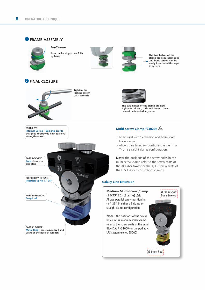
6 OPERATIVE TECHNIQUE
Multi-Screw Clamp (93020) MR
• To be used with 12mm Rod and 6mm shaft bone screws.
• Allows parallel screw positioning either in a T- or a straight clamp configuration.
Note: the positions of the screw holes in the multi-screw clamp refer to the screw seats of the XCaliber fixator or the 1,3,5 screw seats of the LRS fixator T- or straight clamps.
Galaxy Line Extension
Ø 9mm Rod
Ø 6mm Shaft Bone Screws
Medium Multi-Screw Clamp (99-93120) (Sterile) MR
Allows parallel screw positioning (+/- 35°) in either a T-clamp or straight clamp configuration
Note: the positions of the screw holes in the medium screw clamp refer to the screw seats of the Small Blue D.A.F. (31000) or the pediatric LRS system (series 55000)
FAST CLOSURE:Metal Ring - pre closure by hand without the need of wrench
FAST INSERTION:Snap Lock
FAST LOCKING:Cam closure inone step
FLEXIBILITY OF USE:Rotation up to +/- 35°
STABILITY:Internal Spring +Locking profiledesigned to provide high torsional strength on rod
Pre-Closure
Turn the locking screw fully by hand
The two halves of the clamp are now tightened closed, rods and bone screws cannot be inserted anymore
The two halves of the clamp are separated, rods and bone screws can be easily inserted with snap-in system
1 FRAME ASSEMBLY
2 FINAL CLOSURE
Tighten the locking screw with Wrench
OPERATIVE TECHNIQUE 7
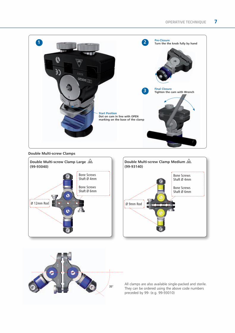
35°
Start PositionDot on cam in line with OPEN marking on the base of the clamp
Pre-ClosureTurn the the knob fully by hand
Final ClosureTighten the cam with Wrench
1 2
3
All clamps are also available single-packed and sterile. They can be ordered using the above code numbers preceded by 99- (e.g. 99-93010)
Double Multi-screw Clamp Large (99-93040)
Double Multi-screw Clamps
Double Multi-screw Clamp Medium (99-93140)
Ø 9mm RodØ 12mm Rod
Bone Screws Shaft Ø 4mm
Bone Screws Shaft Ø 6mm
Bone Screws Shaft Ø 4mm
Bone Screws Shaft Ø 6mm

8 OPERATIVE TECHNIQUE
GALAXY FIXATION™ / TL-HEX CONNECTION SYSTEM
TIBIA PAEDIATRICS APPLICATIONS

OPERATIVE TECHNIQUE 9
EQUIPMENT REQUIRED
INSTRUMENTS Galaxy Fixation™ SYSTEM TRAY
Can accomodate:
RODS & CLAMPS TRAY*
Can accomodate:
* to order any of the Rods or Clamps, single-packed and sterile, please add 99- prior to the part number, ex. 99-93010
TRAY CONFIGURATION
Code Description19940 Multi-screw Clamp Guide11138 Drill Guide d 4.8mm11137 Screw Guide 80mm1-1100201 Drill Bit d 4.8x240mm Coated - Quick Connect11106 Drill Guide d 3.2mm11102 Screw Guide 60mm 1-1300301 Drill Bit d 3.2x140mm Coated - Quick Connect 19955 Trocar19960 Wrist Guide Template with Handle13530 Drill Guide d 2.7mm 1-1355001 Drill Bit d 2.7x127mm Coated - Quick Connect19965 Tapered Trocar M210 T Wrench 93150 Racheting T Handle93155 Screw Shaft Connection 30017 Allen Wrench 5mm 93017 Wrench 5mm Shaft Connection
Code DescriptionLower Tray93010 Large Clamp 93020 Multi-screw Clamp 932400 Rod d 12mm L 400mm 932350 Rod d 12mm L 350mm 932300 Rod d 12mm L 300mm 932250 Rod d 12mm L 250mm 932200 Rod d 12mm L 200mm 932150 Rod d 12mm L 150mm 932100 Rod d 12mm L 100mm 932030 Semi Circular Rod d 12mm large932020 Semi Circular Rod d 12mm medium 932010 Semi Circular Rod d 12mm smallUpper Tray93110 Medium Clamp 93310 Small Clamp 939300 Rod d 9mm L 300mm 939250 Rod d 9mm L 250mm 939200 Rod d 9mm L 200mm 939150 Rod d 9mm L 150mm 939100 Rod d 9mm L 100mm 936200 Rod d 6mm L 200mm 936180 Rod d 6mm L 180mm 936160 Rod d 6mm L 160mm 936140 Rod d 6mm L 140mm 936120 Rod d 6mm L 120mm 936100 Rod d 6mm L 100mm 936080 Rod d 6mm L 80mm 936060 Rod d 6mm L 60mm
Code Description93991C Galaxy Upper + Lower Complete93992C Galaxy Instruments Complete93993C Galaxy Lower + Instruments Complete93996C Galaxy Lower Complete

10 OPERATIVE TECHNIQUE
99-93501 Pelvis Sterile Kit
Consisting of:
99-93502 Lower Limb Diaphyseal Sterile Kit
Consisting of:
99-93503 Ankle Sterile Kit
Consisting of:
Sterile Kit
Besides the sterile pre-packaged kits, Galaxy Fixation™ System offers all clamps and rods pre-packaged and sterile individually. They can be ordered using the code number preceded by 99- (e.g. 99-939300).
Code Description8x93010 Large Clamp1x932350 Rod d 12mm L 350mm1x932300 Rod d 12mm L 300mm2x932200 Rod d 12mm L 200mm4x912640 Self-drilling XCaliber Screws, L 260mm, thread length
40mm1x11138 Drill Guide d 4.8mm1x11137 Screw Guide 80mm1x1-1100101 Drill Bit d 4.8x180mm Coated - Quick Connect1x91150 Bone Screw T Wrench
Code Description6x93010 Large Clamp1x932300 Rod d 12mm L 300mm2x932150 Rod d 12mm L 150mm2x912650 Self-drilling XCaliber Screws, L 260mm, thread length
50mm2x911550 Self-drilling XCaliber Screws, L 150mm, thread length
50mm1x11138 Drill Guide d 4.8mm1x11137 Screw Guide 80mm1x1-1100101 Drill Bit d 4.8x180mm Coated - Quick Connect1x91150 Bone Screw T Wrench
Code Description6x93010 Large Clamp1x932300 Rod d 12mm L 300mm1x932200 Rod d 12mm L 200mm1x932150 Rod d 12mm L 150mm2x911540 Self-drilling XCaliber Screws, L 150mm, thread length
40mm1x11138 Drill Guide d 4.8mm1x11137 Screw Guide 80mm1x1-1100101 Drill Bit d 4.8x180mm Coated - Quick Connect1x91150 Bone Screw T Wrench1x93080 Transfix Pin 80mm - Shaft d.6mm/Thread d.7mm

OPERATIVE TECHNIQUE 11
ANKLE STERILE KIT - TRANSFIX PIN Ø4mm(99-93499)
Can accomodate:
GALAXY MEDIUM - PAEDIATRIC STERILE KIT - Ø4MM SCREW THREAD (99-93521)
GALAXY MEDIUM - PAEDIATRIC STERILE KIT - Ø5MM SCREW THREAD (99-93520)
Code Description4x93010 Large Clamp2x93030 Transitional Clamp1x932300 Rod d 12mm L 300mm1x932200 Rod d 12mm L 200mm1x932150 Rod d 12mm L 150mm2x911540 XCaliber Screws 1x11138 Drill guide d 4.8mm1x11137 Screw Guide 80mm1x1-1100101 Drill Bit d 4.8x180mm1x91150 Universal “T” Wrench1x92080 Transfix Pin thread lenght 80mm, thread Ø 5mm,
shaft 4mm
Code Description2x93140 Double multipin clamp medium2x939250 Rod d 9mm L250mm4x944540 5mm thread self-drilling 150/40
cylindrical screws QC2x11137 Screw guide 80mm1x30017 Allen Wrench 5mm1x93160 QC Wrench
Code Description2x93140 Double multipin clamp medium2x939250 Rod d 9mm L250mm4x945430 4mm thread self-drilling 150/30
0cylindrical screws QC2x11137 Screw guide 80mm1x30017 Allen Wrench 5mm1x93160 QC Wrench

12 OPERATIVE TECHNIQUE
GENERAL INSTRUCTIONS
Screw InsertionScrew positions should be planned with regard to zone of injury; often this may extend beyond the fracture lines visible on X-ray. Further thought into possible future surgeries, including plastic surgical and internal fixation procedures, should be given. X-rays of the fracture in two planes should be available. In general, screws should be placed anterolaterally in the femur; anteriorly (1 cm medial to the tibial crest in an anteroposterior direction) in the tibia; laterally in the proximal third of humerus and posterolaterally in the distal third of the humerus. Screws should be positioned for maximum mechanical stability in each bone segment, with bicortical purchase by the screw threads and with each pin as far apart in each segment as the fracture lines and neighbouring joints allow.
Insert two screws into each main fragment free-hand using the following technique: 1) Make a 15mm incision through skin and deep fascia. Use blunt dissection to reach the underlying bone (Fig. 1).
2) Insert a screw guide perpendicular to the longitudinal axis of the bone. Use a trocar to locate the midline by palpation (Fig. 2).
3) Keeping the screw guide in contact with the cortex by gentle pressure, withdraw the trocar, and tap the screw guide lightly to anchor the pronged end against bone (Fig. 3).
Fig. 1
Fig. 2
Fig. 3
OPERATIVE TECHNIQUE 13
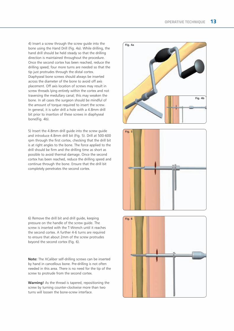
4) Insert a screw through the screw guide into the bone using the Hand Drill (Fig. 4a). While drilling, the hand drill should be held steady so that the drilling direction is maintained throughout the procedure. Once the second cortex has been reached, reduce the drilling speed; four more turns are needed so that the tip just protrudes through the distal cortex.Diaphyseal bone screws should always be inserted across the diameter of the bone to avoid off axis placement. Off axis location of screws may result in screw threads lying entirely within the cortex and not traversing the medullary canal; this may weaken the bone. In all cases the surgeon should be mindful of the amount of torque required to insert the screw. In general, it is safer drill a hole with a 4.8mm drill bit prior to insertion of these screws in diaphyseal bone(Fig. 4b).
5) Insert the 4.8mm drill guide into the screw guide and introduce 4.8mm drill bit (Fig. 5). Drill at 500-600 rpm through the first cortex, checking that the drill bit is at right angles to the bone. The force applied to the drill should be firm and the drilling time as short as possible to avoid thermal damage. Once the second cortex has been reached, reduce the drilling speed and continue through the bone. Ensure that the drill bit completely penetrates the second cortex.
6) Remove the drill bit and drill guide, keeping pressure on the handle of the screw guide. The screw is inserted with the T-Wrench until it reaches the second cortex. A further 4-6 turns are required to ensure that about 2mm of the screw protrudes beyond the second cortex (Fig. 6).
Note: The XCaliber self-drilling screws can be inserted by hand in cancellous bone. Pre-drilling is not often needed in this area. There is no need for the tip of the screw to protrude from the second cortex.
Warning! As the thread is tapered, repositioning the screw by turning counter-clockwise more than two turns will loosen the bone-screw interface.
Fig. 4a
Fig. 4b
Fig. 5
Fig. 6

14 OPERATIVE TECHNIQUE
XCaliber bone screw designThe threaded portion of the XCaliber bone screw tapers from 6.0mm to 5.6mm in diameter in order to provide an increasing radial preload during insertion. This maintains good fixation at the entry cortex which is usually the first area subject to problems of loosening. Despite the tapered profile, some adjustment of bone screw penetration is possible owing to the inherent elasticity of bone. However, the screws should not be backed out for more than two full turns. The screws have a pointed tip and flute which allow them to be inserted as self-drilling implants in cancellous bone without the need for pre-drilling. Direct insertion with a hand drill is advised in most situations, irrespective of whether uncoated or HA coated screws are used. However, when insertion of these self-drilling screws is performed in diaphyseal bone, pre-drilling is recommended; use a 4.8mm drill bit through a drill guide when the bone is hard. If the bone quality is poor or, as in the metaphyseal region, where the cortex is thin, a 3.2mm drill bit should be used.
XCaliber bone screws should never be inserted with a power tool. This may result in high temperatures and cell necrosis from too high insertion speeds. Screw insertion, whether or not pre-drilling has been performed, should always be with the XCaliber Hand Drill (91120) or Rachet T Handle + Screw Shaft Connection (93150 + 93155). The screws have a round shank which is gripped securely by the XCaliber T-handle or Hand Drill. It is important that moderate force is applied initially for the screw to engage and gain entry into the first cortex.
(91120)
(93150)
(93155)

OPERATIVE TECHNIQUE 15
7) Tibial screws are preferentially inserted in the sagittal (anteroposterior) plane. Insert the remaining screws using the same technique (Fig. 7).
Fixator Application8) The two screws in each bone segment are joined byrods of suitable length; each one mounted with twoclamps positioned about 30mm from the skin. Theyare then locked manually by turning the knurled metalring clockwise (Fig. 8).
9) A third rod is then used to join the first two rods together by 2 more clamps, which are not yet tightened. The surgeon now manipulates the fracture, if possible under X-ray control. When the position is satisfactory, the assistant locks all the clamps firmly by tightening the cams with the Universal T-Wrench or the 5mm Allen Wrench (Fig. 9).
Fig. 8
Fig. 7
Fig. 9

16 OPERATIVE TECHNIQUE
10) The screw shafts are then cut with the bone screw cutter (Fig. 10). Although the screws can be cut before insertion, it is difficult to gauge the length accurately, and it is recommended that they are cut after the fixator has been applied. It is important that all of the screws are inserted first, and the fixator applied with the clamps locked firmly over the screws, about 30mm from the skin. The cutter can then be slid over the screw shanks in turn and the screws cut close to the fixator clamps. This will normally result in about 6mm of screw shank protruding from the clamp. The cutter is designed so that it can be used even when screws are in adjacent seats of the multi-screw clamp. The cut ends of the screws can then be protected with screw caps. When cutting the screws, the arms of the cutter should be extended for greater efficiency and the outer end of the screw held.
Fig. 10
Fig. 11 Fig. 12
MULTI-SCREW CLAMPS
Insert the first screw into one of the outer holes of the multi-screw clamp guide using the same technique as described above. Insert the second screw in the remaining outer seat and cut both screw shafts with the bone screw cutter. Lastly, insert the central screw if necessary.
Option 1Use the multi-screw clamp as a template to insert screws perpendicular to the longitudinal axis of the bone (Fig. 11).
Option 2Use the Multi-Screw Clamp Guide 19940 as a template to insert screws perpendicular to the longitudinal axis of the bone (Fig. 12).
OPERATIVE TECHNIQUE 17
APPLICATION BY ANATOMICAL SITE
The external fixator assemblies described in this manual are suggested configurations in order to achieve stability through the optimal use of components and efficiency in application. Each fixator configuration for each anatomical site can conveniently be linked to the adjacent region; this is the rationale for the choice of screw position and rod connections. In so doing, the surgeon can perform damage control stabilisation from pelvis to foot with familiarity of one fixator configuration for each anatomical region.
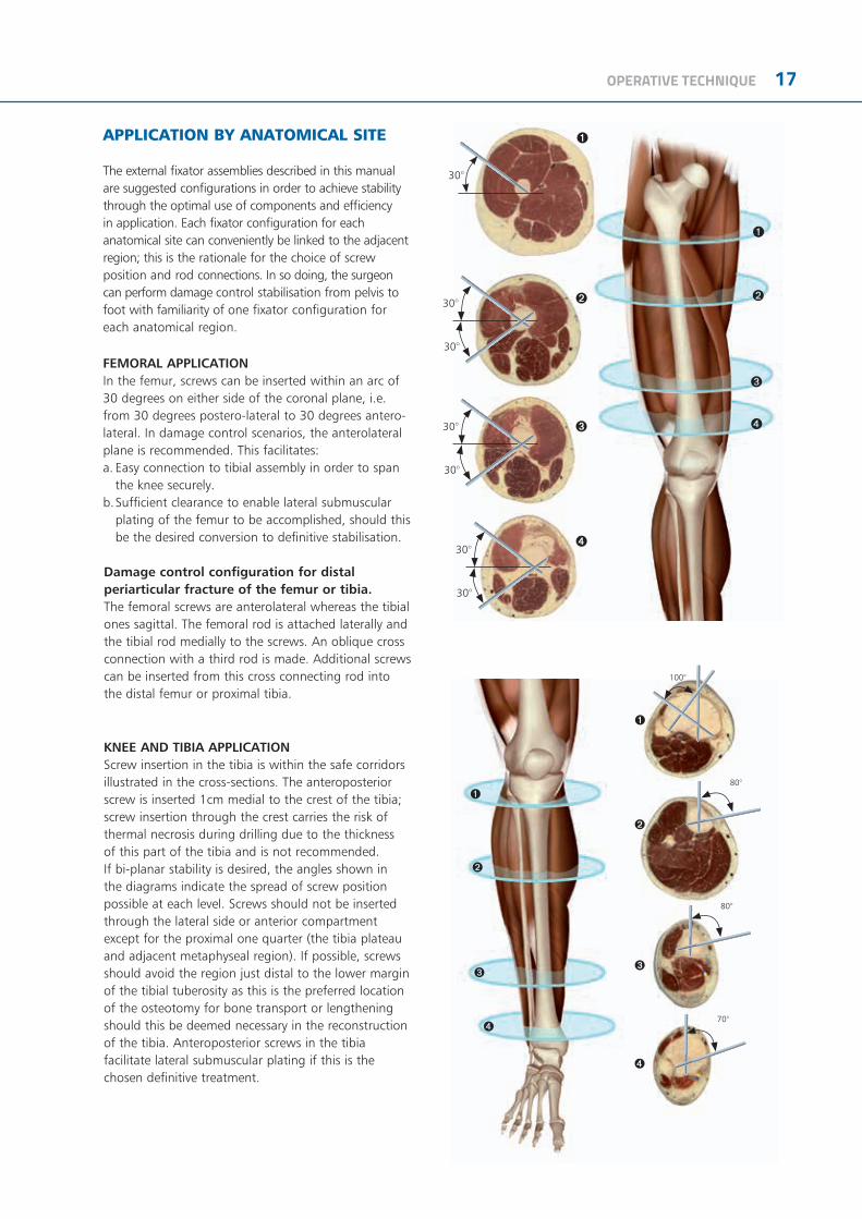
FEMORAL APPLICATIONIn the femur, screws can be inserted within an arc of 30 degrees on either side of the coronal plane, i.e. from 30 degrees postero-lateral to 30 degrees antero-lateral. In damage control scenarios, the anterolateral plane is recommended. This facilitates:a. Easy connection to tibial assembly in order to span
the knee securely.b. Sufficient clearance to enable lateral submuscular
plating of the femur to be accomplished, should this be the desired conversion to definitive stabilisation.
Damage control configuration for distal periarticular fracture of the femur or tibia.The femoral screws are anterolateral whereas the tibial ones sagittal. The femoral rod is attached laterally and the tibial rod medially to the screws. An oblique cross connection with a third rod is made. Additional screws can be inserted from this cross connecting rod into the distal femur or proximal tibia.
30°
30°
30°
➊
➋
➌
➍
➊
➋
➌
➍
30°
30°
30°
30°
80°
80°
70°
100°
➊
➋
➌
➍
➊
➋
➌
➍
KNEE AND TIBIA APPLICATIONScrew insertion in the tibia is within the safe corridors illustrated in the cross-sections. The anteroposterior screw is inserted 1cm medial to the crest of the tibia; screw insertion through the crest carries the risk of thermal necrosis during drilling due to the thickness of this part of the tibia and is not recommended. If bi-planar stability is desired, the angles shown in the diagrams indicate the spread of screw position possible at each level. Screws should not be inserted through the lateral side or anterior compartment except for the proximal one quarter (the tibia plateau and adjacent metaphyseal region). If possible, screws should avoid the region just distal to the lower margin of the tibial tuberosity as this is the preferred location of the osteotomy for bone transport or lengthening should this be deemed necessary in the reconstruction of the tibia. Anteroposterior screws in the tibia facilitate lateral submuscular plating if this is the chosen definitive treatment.

18 OPERATIVE TECHNIQUE
FEMUR KNEE
TIBIA
ANKLE

OPERATIVE TECHNIQUE 19
PAEDIATRICS APPLICATIONS
20 OPERATIVE TECHNIQUE
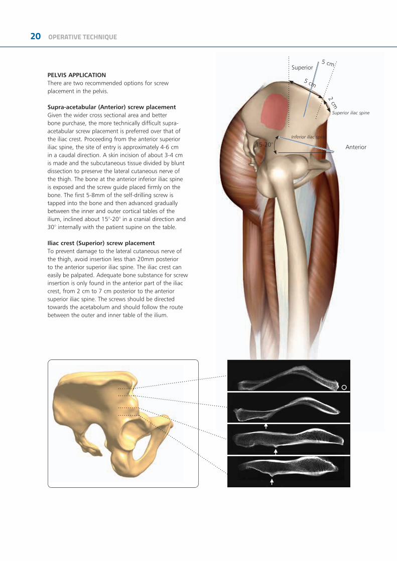
PELVIS APPLICATIONThere are two recommended options for screw placement in the pelvis.
Supra-acetabular (Anterior) screw placement Given the wider cross sectional area and better bone purchase, the more technically difficult supra-acetabular screw placement is preferred over that of the iliac crest. Proceeding from the anterior superior iliac spine, the site of entry is approximately 4-6 cm in a caudal direction. A skin incision of about 3-4 cm is made and the subcutaneous tissue divided by blunt dissection to preserve the lateral cutaneous nerve of the thigh. The bone at the anterior inferior iliac spine is exposed and the screw guide placed firmly on the bone. The first 5-8mm of the self-drilling screw is tapped into the bone and then advanced gradually between the inner and outer cortical tables of the ilium, inclined about 15°-20° in a cranial direction and 30° internally with the patient supine on the table.
Iliac crest (Superior) screw placementTo prevent damage to the lateral cutaneous nerve of the thigh, avoid insertion less than 20mm posterior to the anterior superior iliac spine. The iliac crest can easily be palpated. Adequate bone substance for screw insertion is only found in the anterior part of the iliac crest, from 2 cm to 7 cm posterior to the anterior superior iliac spine. The screws should be directed towards the acetabolum and should follow the route between the outer and inner table of the ilium.
15-20°
Superior iliac spine
Inferior iliac spine
Anterior
5 cm
2 cm5 cm
Superior
OPERATIVE TECHNIQUE 21
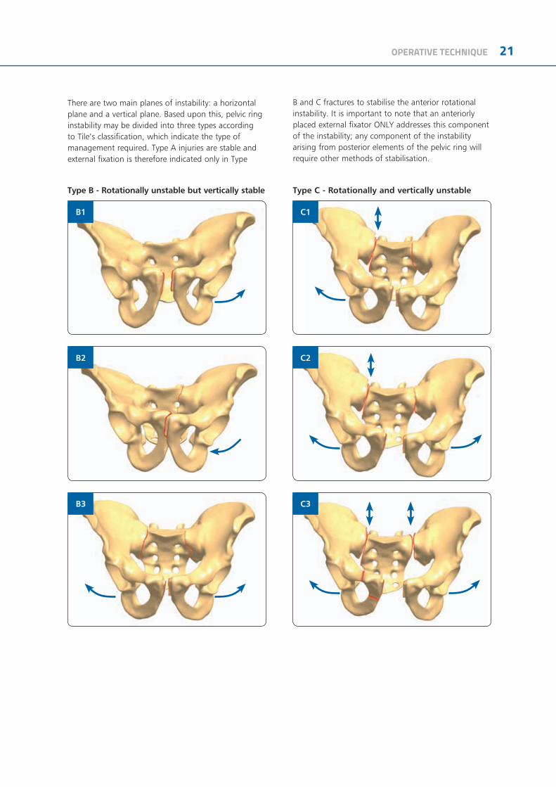
Type B - Rotationally unstable but vertically stable Type C - Rotationally and vertically unstable
There are two main planes of instability: a horizontal plane and a vertical plane. Based upon this, pelvic ring instability may be divided into three types according to Tile’s classification, which indicate the type of management required. Type A injuries are stable and external fixation is therefore indicated only in Type
B and C fractures to stabilise the anterior rotational instability. It is important to note that an anteriorly placed external fixator ONLY addresses this component of the instability; any component of the instability arising from posterior elements of the pelvic ring will require other methods of stabilisation.
B2
C3
B1
B3
C1
C2

22 OPERATIVE TECHNIQUE
In type B1 and B3 injuries a diastasis of the symphysis greater than 2.5 cm indicates a severe rotational instability and an increased pelvic volume. Therefore an external fixator is applied as an emergency procedure to reduce the pelvic volume and stop bleeding. However, the true instability in this “open book” fracture cannot securely be estimated by the AP X-ray. Clinical investigation (i.e. by testing stability manually) is mandatory for the indication of immediate external fixation.
In type B2 injuries external fixation is rarely necessary as an emergency procedure because the impaction of the fracture site leads to a sufficient stability and there is no increased pelvic volume. CT investigation may clarify the true fracture pattern and subsequently the correct treatment protocol, and is also recommended to evaluate the posterior structures (sacro-iliac joint, sacrum, posterior part of iliac bone).
Type C injuries are always considered unstable. In the emergency situation the fixator is used on the anterior side of the pelvic ring with screws either in the supra-acetabular region and/or at the iliac crest to increase stability. The posterior part of the pelvic ring cannot be fully controlled by the external fixator in terms of weight bearing. Nevertheless, external fixation allows enough stability to reduce the pelvic volume and therefore the amount of bleeding. After resuscitation of the patient and further investigation, subsequent internal fixation of the posterior part of the pelvic ring may be considered.
ANTERIOR APPLICATION
ILIAC CREST APPLICATION
HYBRID APPLICATION

OPERATIVE TECHNIQUE 23
OPERATIVE TECHNIQUE
1) Commence with the uninjured side. Make an incision just caudal to the anterior superior iliac spine to course over the anterior inferior iliac spine. Identify the lateral edge of Sartorius muscle and retract medially. The rounded tendinous portion of rectus femoris can be seen arising from the anterior inferior iliac spine. Make an incision down to bone just cranial to this spine. Roughen this area with a periosteal elevator. Tap a self-drilling screw 5-8mm into the roughened area in order to engage the bony cortex and advance the screw using turns of the T-handle. Aim the screw 15-20 degrees cranial to avoid penetration of the hip joint and to enter the widest part of the ilium (Fig. 1).
2) Insert two Kirschner wires to establish the orientation of the hemipelvis: one from the iliac crest along the inner table of the ilium and one along the outer table (Fig. 2). Insert a self-drilling screw, gently tap it through the cortex and screw it home with the T-wrench, without forcing the screw in any direction. The depth of insertion is 40-50mm (almost the entire thread length). In young patients (16 years and under), use a 3.2mm drill bit and drill guide to penetrate the hard cortex to a depth of 1 cm. Screws in the iliac crest should be inserted in a region from 2 cm to 7 cm posterior to the anterior superior iliac spine. These screws should be directed towards the acetabulum and should follow the route between the outer and inner table of the ilium.
3) The two screws in each hemipelvis are joined by rods of suitable length, each one mounted with 2 clamps. They are then locked manually by turning the knurled metal ring clockwise. Two rods are then used to link the first two rods across the width of the pelvis (this can be at two levels as shown in Fig. 3) through use of additional clamps which are attached but not yet tightened. The surgeon now manipulates the fracture, if possible under X-ray control; when the position is satisfactory, the assistant locks the clamps firmly by tightening the cams clockwise with the Universal T-Wrench or the 5mm Allen Wrench (Fig. 3).
Fig. 1
Fig. 2
Fig. 3
24 OPERATIVE TECHNIQUE
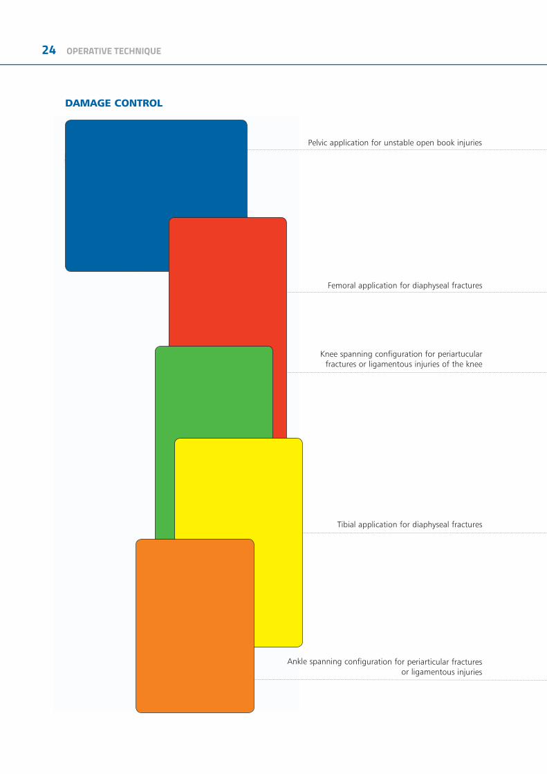
DAMAGE CONTROL
Pelvic application for unstable open book injuries
Femoral application for diaphyseal fractures
Knee spanning configuration for periartucular fractures or ligamentous injuries of the knee
Tibial application for diaphyseal fractures
Ankle spanning configuration for periarticular fracturesor ligamentous injuries

OPERATIVE TECHNIQUE 25
26 OPERATIVE TECHNIQUE
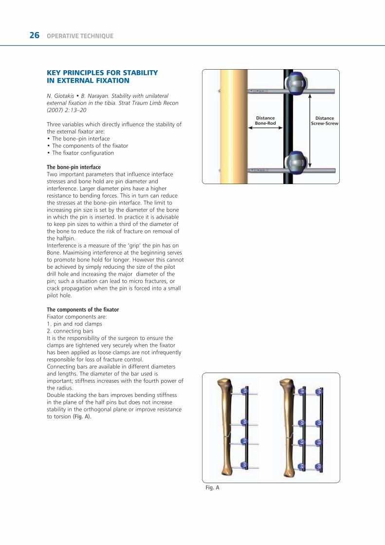
DistanceBone-Rod
DistanceScrew-Screw
KEY PRINCIPLES FOR STABILITY IN EXTERNAL FIXATION
N. Giotakis • B. Narayan. Stability with unilateral external fixation in the tibia. Strat Traum Limb Recon (2007) 2:13–20
Three variables which directly influence the stability of the external fixator are:• The bone–pin interface• The components of the fixator• The fixator configuration
The bone-pin interfaceTwo important parameters that influence interfacestresses and bone hold are pin diameter and interference. Larger diameter pins have a higher resistance to bending forces. This in turn can reduce the stresses at the bone–pin interface. The limit to increasing pin size is set by the diameter of the bone in which the pin is inserted. In practice it is advisable to keep pin sizes to within a third of the diameter of the bone to reduce the risk of fracture on removal of the halfpin.Interference is a measure of the ‘grip’ the pin has onBone. Maximising interference at the beginning serves to promote bone hold for longer. However this cannot be achieved by simply reducing the size of the pilot drill hole and increasing the major diameter of the pin; such a situation can lead to micro fractures, or crack propagation when the pin is forced into a small pilot hole.
The components of the fixatorFixator components are:1. pin and rod clamps2. connecting barsIt is the responsibility of the surgeon to ensure the clamps are tightened very securely when the fixator has been applied as loose clamps are not infrequently responsible for loss of fracture control.Connecting bars are available in different diameters and lengths. The diameter of the bar used is important; stiffness increases with the fourth power of the radius. Double stacking the bars improves bending stiffness in the plane of the half pins but does not increase stability in the orthogonal plane or improve resistance to torsion (Fig. A).
Fig. A

OPERATIVE TECHNIQUE 27
The fixator configurationThe way by which the fixator is assembled can change stability through:1. the number and spread of pins along the segments, and2. the distance between connecting rods and bone
According to the general principles of external fixation, an increase in stiffness is provided by increasing pin number from two to three in any one segment. The added benefit from increasing pin number from three to four is minimal, therefore three pins per segment is advised. The external fixator configuration will depend on the amount of bone contact at the fracture site, the fracture pattern and the segment or segments of bone involved. This manual provides examples of how fixator configuration can be augmented in some common fracture patterns to create stability sufficient to allow rehabilitation of the patient. As for pin spread, the ‘near and far’ rule provides a guide; pins should be spread along a segment of bone such that the segment is spanned. The proximity of any pin to the fracture itself is cautioned as the pin may be within the fracture haematoma and thereby carry the risk of a pin site infection spreading to within the fracture. A rule of thumb of staying at least 2 cm from the nearest fracture line helps (Fig. B).
The distance of the connecting bar from bone is determined by the depth of soft tissue in between. Bringing the connecting bar closer to bone improves stability and in general it should be kept as close as possible with enough room to facilitate pin site care - 40- 50mm (roughly 2 finger breadths) from the bone surface if feasible (Fig. C).
Biplanar Unilateral Configuration
Additional stability can be achieved with a biplanar unilateral configuration, which has particular advantages for control of bending in both sagittal and coronal planes (and in planes in between) as well as high resistance against torsion.
Fig. B
Fig. C
28 OPERATIVE TECHNIQUE
MRI INFORMATION
Galaxy System Fixator Components are labeled MR CONDITIONAL MR according to the terminology specified in ASTM F2503 Standard Practice for Marking Medical Devices and Other Items in the Magnetic Resonance Enviroment.
Non-clinical testing has demonstrated that the Galaxy System Fixator Components is MR Conditional according to the terminology specified in ASTM F2503 Standard Practice for Marking Medical Devices and Other Items in the Magnetic Resonance Environment. Non-clinical testing, done according to ASTM F2052-06, F2213-06, F2182–11, F2119-07, demonstrated that a patient with the Galaxy Fixation™ System can be safely scanned under the following conditions:• Static magnetic field of 1.5 Tesla and 3.0Tesla• Maximum spatial magnetic field gradient of 900-Gauss/cm (90mT/cm)• Maximum whole-body-averaged specific absorption rate (SAR) of 4.0 W/kg in the First Level Controlled Mode for 15 minutes of scanning.• No local transmit/receive coils must be used on the device.• The Galaxy Fixation System must be entirely outside the MR scanner bore. No part of the Galaxy Fixation System must extend into the MR bore. Therefore MR scanning of body parts where the Galaxy Fixation System is located is Contraindicated.
Displacement InformationThe system will not present an additional risk or hazard to a patient in the 1.5Tesla and 3Tesla MR environment with regard to translational attraction or migration and torque.
Heating InformationComprehensive electromagnetic computer modeling and experimental testing was performed on the following systems:
1.5-Tesla/64-MHz: Magnetom, Siemens Medical Solutions, Malvern, PA. Software Numaris/4, Version Syngo MR 2002B DHHS Active-shielded, horizontal field scanner
3-Tesla/128-MHz: Excite, HDx, Software 14X.M5, General Electric Healthcare, Milwaukee, WI, Active-shielded, horizontal field scanner to determine the worst heating in seven configurations of Orthofix Galaxy Fixation System. From these studies, it is concluded that once the entire external fixation frame is visible outside the MRI bore, the maximum heating is less than 2 degree Celsius. In non-clinical testing the worst scenarios produced the following temperature rises during MRI under the conditions reported above:
1.5 Tesla System 3.0 Tesla SystemGalaxy Fixation™ System Minutes of scanning 15 15Calorimetry measured values, whole body averaged SAR (W/kg) 2.2 W/Kg 2.5 W/KgHighest temperature Rise less than (°C) 2 C 2 C
Please note that temperature changes reported apply to the designed MR systems and characteristics used. If a different MR system is used, temperature changes may vary but are expected to be low enough for safe scanning as long as all Galaxy System Fixator Components are placed outside the MR bore.
MR PATIENT SAFETYMRI in patients with Galaxy Fixation System can only be performed under these parameters. It is not allowed to scan the Galaxy Fixation System directly. Using other parameters, MRI could result in serious injury to the patient. When the Galaxy Fixation System is used in conjunction with other External Fixation Systems please be advised that this combination has not been tested in the MR environment and therefore higher heating and serious injury to the patient may occur. Because higher in vivo heating cannot be excluded, close patient monitoring and communication with the patient during the scan is required. Immediately abort the scan if the patient reports burning sensation or pain.
Galaxy Fixation System can only be guaranteed for MRI when using the following components to build a frame:
NOTE: *the following components are listed in non-sterile configuration. Please consider that the same MRI information and performance are applicable to the same components in gamma-sterile configuration, code number preceeded by 99- (e.g 99-93030).
References1) Summary, conclusions and recommendations: adverse temperature levels in the human body. Goldstein L.S., Dewhirst M.W., Repacholi M., Kheifets L. Int. J. Hyperthermia Vol 19 N. 2003 pag 373-384.2) Assessment of bone viability after heat trauma Eriksson R.A., Albrektsson T., Magnusson B. Scand J Plast Reconst Surg 18:261-68 1984.3) Temperature threshold levels for heat-induced bone tissue injury: A vital-microscopic study in the rabbit Eriksson A.R., Albrektsson T. J Prosthet Dent. 1983 Jul;50(1):101-7.
OPERATIVE TECHNIQUE 29
RODS*Code Description932100 Rod 100mm long, 12mm diameter932150 Rod 150mm long, 12mm diameter932200 Rod 200mm long, 12mm diameter932250 Rod 250mm long, 12mm diameter932300 Rod 300mm long, 12mm diameter932350 Rod 350mm long, 12mm diameter932400 Rod 400mm long, 12mm diameter99-932450 Rod 450mm long, 12mm diameter, sterile**99-932500 Rod 500mm long, 12mm diameter, sterile**99-932550 Rod 550mm long, 12mm diameter, sterile**99-932600 Rod 600mm long, 12mm diameter, sterile**99-932650 Rod 650mm long, 12mm diameter, sterile**939100 Rod 100mm long, 9mm diameter939150 Rod 150mm long, 9mm diameter939200 Rod 200mm long, 9mm diameter939250 Rod 250mm long, 9mm diameter939300 Rod 300mm long, 9mm diameter936060 Rod 60mm long, 6mm diameter936080 Rod 80mm long, 6mm diameter936100 Rod 100mm long, 6mm diameter936120 Rod 120mm long, 6mm diameter936140 Rod 140mm long, 6mm diameter936160 Rod 160mm long, 6mm diameter936180 Rod 180mm long, 6mm diameter936200 Rod 200mm long, 6mm diameter
CLAMPS*Code Description93010 Large Clamp93110 Medium Clamp93310 Small Clamp93020 Multi-screw Clamp93030 Large-Medium Transition Clamp93120 Medium Multi-screw Clamp99-93040 Large Double Multiscrew Clamp99-93140 Medium Double Multiscrew Clamp
ELBOW HINGE*Code Description93410 Elbow Hinge
The Orthofix Galaxy Fixation System components not listed above have not been tested for heating, migration, or image artifact in the MR environment, and their safety is unknown. Scanning a patient carrying a frame that includes these components may result in patient injury.
XCALIBER CYLINDRICAL BONE SCREWS*Code Shaft Ø Thread Ø Total L Thread L942630 6 6 260 30942640 6 6 260 40942650 6 6 260 50942660 6 6 260 60942670 6 6 260 70942680 6 6 260 80942690 6 6 260 90941630 6 6 180 30941640 6 6 180 40941650 6 6 180 50941660 6 6 180 60941670 6 6 180 70941680 6 6 180 80941690 6 6 180 90942540 6 5 260 40942550 6 5 260 50942560 6 5 260 60942570 6 5 260 70942580 6 5 260 80942590 6 5 260 90943540 6 5 220 40943550 6 5 220 50943560 6 5 220 60943570 6 5 220 70941540 6 5 180 40941550 6 5 180 50941560 6 5 180 60944530 6 5 150 30944535 6 5 150 35944540 6 5 150 40944550 6 5 150 50945530 6 5 120 30945535 6 5 120 35945540 6 5 120 40946420 6 4 180 20946430 6 4 180 30946440 6 4 180 40945420 6 4 150 20945430 6 4 150 30945440 6 4 150 40944420 6 4 120 20944430 6 4 120 30944440 6 4 120 40943420 6 4 100 20943430 6 4 100 30943440 6 4 100 40948320 4 3 120 20948325 4 3 120 25948335 4 3 120 35947320 4 3 100 20947325 4 3 100 25M310 3 3 - 2,5 50 18M311 3 3 - 2,5 60 20M312 3 3 - 2,5 60 25M313 3 3 - 2,5 60 30M321 3 3 - 2,5 70 15M314 3 3 - 2,5 70 20M315 3 3 - 2,5 70 25M316 3 3 - 2,5 70 30M317 3 3 - 2,5 100 30
XCALIBER BONE SCREWS*Code Shaft Ø Thread Ø Total L Thread L912630 6 6 - 5,6 260 30912640 6 6 - 5,6 260 40912650 6 6 - 5,6 260 50912660 6 6 - 5,6 260 60912670 6 6 - 5,6 260 70912680 6 6 - 5,6 260 80912690 6 6 - 5,6 260 90911530 6 6 - 5,6 150 30911540 6 6 - 5,6 150 40911550 6 6 - 5,6 150 50911560 6 6 - 5,6 150 60911570 6 6 - 5,6 150 70911580 6 6 - 5,6 150 80911590 6 6 - 5,6 150 90
BONE SCREWS*Code Shaft Ø Thread Ø Total L Thread L10190 6 4,5 - 3,5 70 2010191 6 4,5 - 3,5 80 2010108 6 4,5 - 3,5 80 3010135 6 4,5 - 3,5 100 2010136 6 4,5 - 3,5 100 3010105 6 4,5 - 3,5 100 4010137 6 4,5 - 3,5 120 2010138 6 4,5 - 3,5 120 3010106 6 4,5 - 3,5 120 4035100 4 3,3 - 3 70 2035101 4 3,3 - 3 80 35
* Products may not be available in all markets because product availability is subject to the regulatory and/or medical practices in individual markets. Please contact your Orthofix representative if you have questions about the availability of Orthofix products in your area.
** Special order only.

0123
Manufactured by: ORTHOFIX SrlVia Delle Nazioni 9, 37012 Bussolengo (Verona), ItalyTelephone +39 045 6719000, Fax +39 045 6719380
www.orthofix.com GF-1102-OPT-E0 I 11/18
Distributed by:
Caution: Federal law (USA) restricts this device to sale by or on the order of a physician. Proper surgical procedure is the responsibility of the medical professional. Operative techniques are furnished as an informative guideline. Each surgeon must evaluate the appropriateness of a technique based on his or her personal medical credentials and experience. Please refer to the “Instructions for Use” supplied with the product for specific information on indications for use, contraindications, warnings, precautions, adverse reactions and sterilization.
Electronic Instructions for use available at the website http://ifu.orthofix.it Electronic Instructions for use - Minimum requirements for consultation:• Internet connection (56 kbps)• Device capable to visualize PDF (ISO/IEC 32000-1) files• Disk space: 50Mbites Free paper copy can be requested to customer service (delivery within 7 days):tel +39 045 6719301, fax +39 045 6719370, e-mail: [email protected]


![Colorectal 2018 brochure[1] p1keck.usc.edu/wp-content/uploads/2018/03/final_2018...pre-malignant colorectall conditions. • Integrate current management guidelines and operative indications](https://img.pdfslide.net/doc/110x75/5f0499aa7e708231d40ec5fe/colorectal-2018-brochure1-pre-malignant-colorectall-conditions-a-integrate.jpg)