Embed Size (px)
Citation preview

Galaxy Power RIOInstaller Manual
Honeywell Security
Galaxy Dimension Installer Manual
2
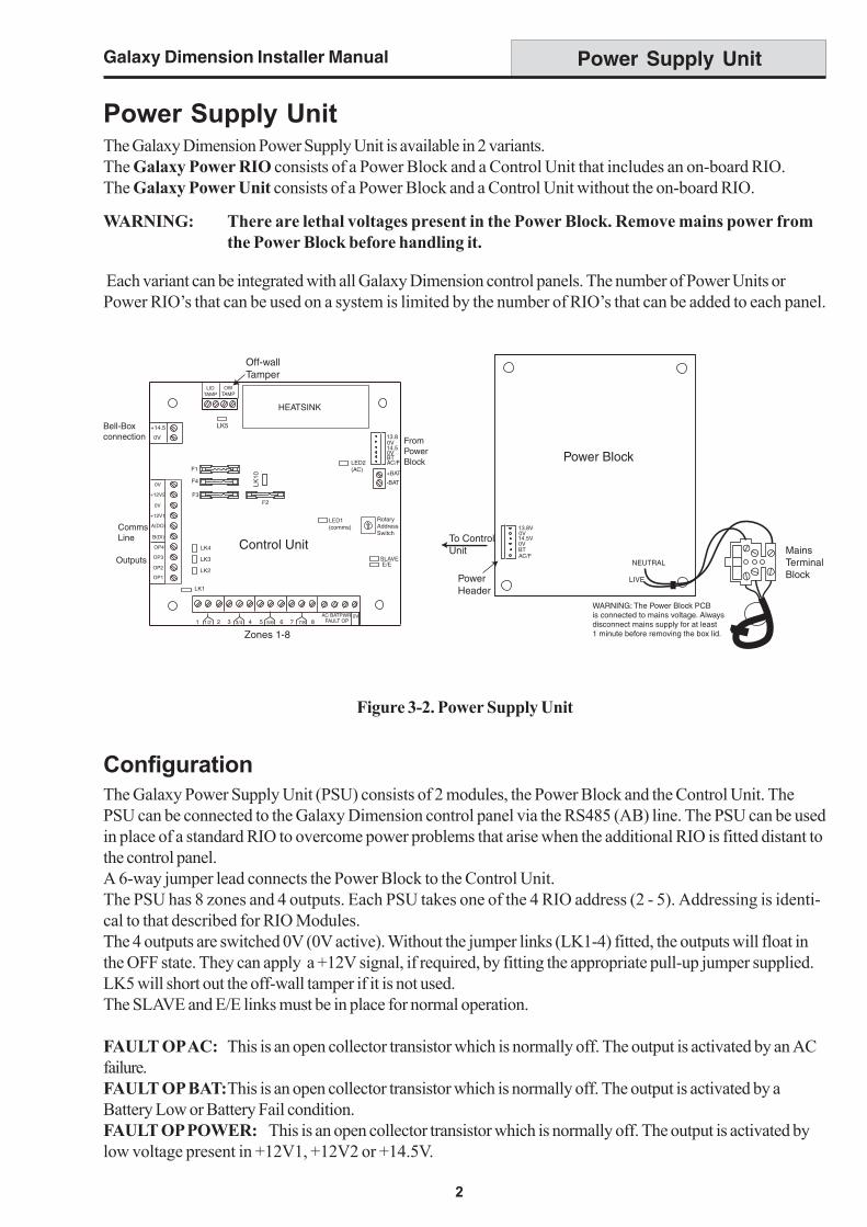
Figure 3-2. Power Supply Unit
Power Supply Unit
Power Supply UnitThe Galaxy Dimension Power Supply Unit is available in 2 variants.The Galaxy Power RIO consists of a Power Block and a Control Unit that includes an on-board RIO.The Galaxy Power Unit consists of a Power Block and a Control Unit without the on-board RIO.
WARNING: There are lethal voltages present in the Power Block. Remove mains power fromthe Power Block before handling it.
Each variant can be integrated with all Galaxy Dimension control panels. The number of Power Units orPower RIO’s that can be used on a system is limited by the number of RIO’s that can be added to each panel.
ConfigurationThe Galaxy Power Supply Unit (PSU) consists of 2 modules, the Power Block and the Control Unit. ThePSU can be connected to the Galaxy Dimension control panel via the RS485 (AB) line. The PSU can be usedin place of a standard RIO to overcome power problems that arise when the additional RIO is fitted distant tothe control panel.A 6-way jumper lead connects the Power Block to the Control Unit.The PSU has 8 zones and 4 outputs. Each PSU takes one of the 4 RIO address (2 - 5). Addressing is identi-cal to that described for RIO Modules.The 4 outputs are switched 0V (0V active). Without the jumper links (LK1-4) fitted, the outputs will float inthe OFF state. They can apply a +12V signal, if required, by fitting the appropriate pull-up jumper supplied.LK5 will short out the off-wall tamper if it is not used.The SLAVE and E/E links must be in place for normal operation.
FAULT OP AC: This is an open collector transistor which is normally off. The output is activated by an ACfailure.FAULT OP BAT:This is an open collector transistor which is normally off. The output is activated by aBattery Low or Battery Fail condition.FAULT OP POWER: This is an open collector transistor which is normally off. The output is activated bylow voltage present in +12V1, +12V2 or +14.5V.
1 1/2 2 3 3/4 4 5 5/6 6 7 7/8 8
Zones 1-8
HEATSINK
CommsLine
Outputs
RotaryAddressSwitch
AC BATPWR 0V
OP1
OP2
OP3
OP4
LIDTAMP
OWTAMP
+14.5
0V
+12V1
A(DO)
B(DI)
F1
F4
F3F2
LK1
LK2
LK3
LK4
-BAT
+BAT
AC/FBT0V14.50V13.8
LED1(comms)
LED2(AC)
Control Unit
+12V2
0V
0V
FAULT OP
Off-wallTamper
FromPowerBlock
Bell-Boxconnection
LK5
LK10
SLAVEE/E
Mains Terminal BlockPower
Header
To ControlUnit
Power Block
NEUTRAL
LIVE
13.8V0V14.5V0VBTAC/F
WARNING: The Power Block PCBis connected to mains voltage. Alwaysdisconnect mains supply for at least1 minute before removing the box lid.

Galaxy Dimension Installer Manual
3
Power Supply Unit (cont’d)
Figure 3-3. Enclosure Base
2. Secure the panel base to the wall using three 1.5" No. 8 round head steel screws through the holesprovided.
The mains cable used must be a three core type (with green/yellow earth insulation) of adequate currentcarrying capacity.
3. Connect the mains cable to the mains terminal block as follows:
• blue wire to the terminal marked N (Neutral)• green/yellow wire to the terminal marked (Earth)• brown wire to the terminal marked L (Live)
NOTE: No other connections to the mains connector are permitted.
All wiring must be in accordance with local regulations and the installation must conform to EN60950.
4. Power up by applying mains first. This unit can be powered up from the battery by momentarily shortingLK10. Never leave LK10 connected, as deep discharge of the battery will occur. LK10 is for start-uponly.
Installation InstructionsThe installation and wiring must be performed by a competent engineer. The Galaxy Dimension Power SupplyUnit must be connected to the a.c. mains supply (230/240 Va.c. 50Hz) via a fused connection outlet. The fusein the mains outlet must not exceed 3A.The Galaxy Dimension Power Supply Unit comes installed in the metal enclosure base. The installation proce-dure of the panel base is as follows:1. Route the mains cable through the hole on the right hand side of the enclosure base. Securely anchor
the cable to the box using the tie-wrap as shown in the following Figure:
Tie wrap
Mains cable
Terminalblock
Keyholeslot (top)
Enclosurebase
Attaching hole Attaching hole
ControlUnit
PowerBlock
Off-WallTamper
Micro-switch
Lid TamperMicroswitch
6-way jumper lead
from power block
to control unit

Galaxy Dimension Installer Manual
4
BatteryThe minimum capacity battery to supply the PSU is 1x 7Ah. The maximum capacity battery to supply thePSU is 2 x 17Ah.
Battery TestA battery test on full load is automatically performed once an hour and during the Engineer Mode exitingprocedure. If the battery voltage falls to 10 V while the Power Supply Unit is running on the battery, then it isautomatically disconnected to prevent deep discharge of the battery.
SpecificationsElectrical (based on 34 Ah battery and UK grade 3 compliance)
Input voltage: 230V a.c. (+10%/-15%) @50HzOutput voltage (nominal): 13.8V & 14.5VOutput current (max): 3.0AOperating temperature: -10 deg C to +40 deg C
Aux1 & Aux2Output voltage (nominal): 13.8VOutput current (max): 0.75A each
14.5V Output (French variant only)Output voltage (nominal): 14.5VOutput current (max): 0.15A (when using this current, the AUX1 & AUX2 currents will
be reduced by an equivalent amount).
Battery charge current (max): 1.4AMaximum ripple voltage: less than 100mV
FusesF1 (14.5V) 500mA - 20mm anti-surgeF2 (Battery) 1.6A - 20mm anti-surgeF3 ( 12V Aux1) 1.0A - 20mm anti-surgeF4 (12V Aux2) 1.0A - 20mm anti-surge
EN50131 ComplianceThis product is suitable for use in systems designed to comply with EN50131-6 and PD6662:2004.
Security Grade - 3Environmental Class - IIPower Supply Type - A
Power Supply Unit (cont’d)