Embed Size (px)
Citation preview

EUROCONTROL
DIS/ATD Unit
DOC. CoE-TP-02002
September 2002
G.A.M.E.Aircraft Performance Model Description
by
Patrick Calders
EUROPEAN ORGANISATION FOR THE SAFETY
OF
AIR NAVIGATION
EUROCONTROL
Rue de la Fusée, 96
B - 1130 Brussels

G.A.M.E. Consolidation Error! Reference source not found.2Error! Reference source not found. Error! Reference source not found.
ii
Purpose of the DocumentThis document provides a General Description of both the GAME and BADA Aircraft Performance Models,which can be used as the basis for developing aircraft performance simulations.
Revision History
0.1 8 October 1998 Initial Draft
0.2 15 October 1998 2nd Draft
0.3 23 October 1998 3rd Draft
0.4 5 November 1998 Including remarks made during meeting of 02-nov-98 at EHQ
0.5 16 November 1998 Including remarks made during meeting of 12-nov-98 at EHQ
0.6 1 December 1998 Including remarks made during meeting of 17-nov-98 at EHQ
1.0 31 May 1999 Including upgrades to correctly model BoeingIncluding FMS-behaviour.
1.1 16 August 2000 Upgrade Fuel-flow formulas
2.0 10 September 2002 Complete review of the document
DistributionEurocontrol
Raketstraat 961130 BrusselBelgium
G.A.M.E. Consolidation Error! Reference source not found.2Error! Reference source not found. Error! Reference source not found.
iii
Contents
1 INTRODUCTION ........................................................................................................................................... 5
1.1 PERFORMANCE MODELLING....................................................................................................................... 51.2 THE GENERAL AIRCRAFT MODELLING ENVIRONMENT .............................................................................. 51.3 AIRCRAFT MODEL COMPONENTS ............................................................................................................... 61.4 APPLICATION PROGRAMMER’S INTERFACE ................................................................................................ 7
2 REFERENCES ................................................................................................................................................ 8
3 DOCUMENT CONVENTIONS..................................................................................................................... 9
3.1 NAMING CONVENTIONS.............................................................................................................................. 93.2 DEFINITIONS AND UNITS USED ................................................................................................................. 10
4 AIRCRAFT TYPE CATEGORIES ............................................................................................................. 11
5 FLIGHT PHASES ......................................................................................................................................... 12
6 CONFIGURATIONS .................................................................................................................................... 13
6.1 HIGH-LIFT DEVICES ................................................................................................................................. 136.2 DRAG DEVICES......................................................................................................................................... 146.3 OTHER DEVICES WITH INFLUENCE ON PERFORMANCE .............................................................................. 14
7 ENGINE SPECIFICS.................................................................................................................................... 15
7.1 NO FLAT-RATING...................................................................................................................................... 157.2 ONLY ISA FLAT-RATING.......................................................................................................................... 167.3 ONLY ALTITUDE FLAT-RATING ................................................................................................................ 167.4 INDEPENDENT ISA AND ALTITUDE FLAT-RATING BOTH PRESENT ............................................................ 177.5 FLAT-RATE ISA DEPENDS UPON ALTITUDE .............................................................................................. 18
8 BASIC FORMULAS ..................................................................................................................................... 19
8.1 GAME...................................................................................................................................................... 198.2 BADA...................................................................................................................................................... 22
9 AIRCRAFT DATA........................................................................................................................................ 25
9.1 REFERENCE DATA .................................................................................................................................... 259.2 GENERAL INFORMATION........................................................................................................................... 269.3 DIMENSIONS ............................................................................................................................................. 309.4 RECOMMENDED SPEEDS ........................................................................................................................... 329.5 PERFORMANCE ENVELOPE........................................................................................................................ 359.6 IMPORTANT SPEEDS .................................................................................................................................. 519.7 CONFIGURATION MANAGEMENT .............................................................................................................. 539.8 IN-FLIGHT PERFORMANCE – BASIC........................................................................................................... 609.9 IN-FLIGHT PERFORMANCE – DETAILED .................................................................................................... 679.10 FUEL CONSUMPTION................................................................................................................................. 739.11 TAKE-OFF PERFORMANCE........................................................................................................................ 789.12 LANDING PERFORMANCE.......................................................................................................................... 809.13 GROUND MOVEMENTS ............................................................................................................................. 81
10 AIRCRAFT OPERATION PARAMETERS .......................................................................................... 84
10.1 APPROACH SPEED QUALIFIERS................................................................................................................. 8410.2 NON-IDLE DESCENTS................................................................................................................................ 84
11 FUNCTIONS USED TO DERIVE OTHER FLIGHT-PARAMETERS .............................................. 85
11.1 CONVERTING PRESSURE ALTITUDE INTO GEOGRAPHICAL ALTITUDE....................................................... 85
G.A.M.E. Consolidation Error! Reference source not found.2Error! Reference source not found. Error! Reference source not found.
iv
11.2 CONVERTING PRESSURE VERTICAL-SPEED INTO GEO VERTICAL-SPEED................................................... 8611.3 TROPOPAUSE ALTITUDE ........................................................................................................................... 8611.4 CROSS-OVER ALTITUDE CAS-MACH PROFILES ........................................................................................ 8711.5 ACCELERATION/DECELERATION FOR A GIVEN VERTICAL SPEED.............................................................. 8811.6 TURN-RATE FROM BANK-ANGLE.............................................................................................................. 8811.7 TURN-RATE FROM G-LOAD ...................................................................................................................... 8911.8 FUEL CONSUMPTION DURING REDUCED THRUST POWER-SETTINGS. ........................................................ 9011.9 FUEL CONSUMPTION FOR SPECIFIED RATE-OF-DESCENT........................................................................... 9011.10 TAKE-OFF ACCELERATION AT REDUCED TAKE-OFF THRUST................................................................. 9011.11 ATMOSPHERIC PRESSURE FROM PRESSURE ALTITUDE .......................................................................... 9111.12 RATE-OF-CHANGE OF ATMOSPHERIC PRESSURE FROM VERTICAL SPEED .............................................. 9111.13 VERTICAL SPEED FROM RATE-OF-CHANGE OF ATMOSPHERIC PRESSURE .............................................. 92
12 APPROXIMATION FORMULAS........................................................................................................... 93
12.1 TAS FROM CAS ....................................................................................................................................... 9312.2 CGR_MAX DERIVED FROM VERTICAL SPEED FOR CST-CAS PROFILE ..................................................... 9312.3 CAS FROM MACH..................................................................................................................................... 94

G.A.M.E. Consolidation Error! Reference source not found.2Error! Reference source not found. Error! Reference source not found.
5
1 Introduction
1.1 Performance Modelling
Aircraft Performance Modelling is done in different ways, depending upon the needs of a particular type ofsimulation. This ranges from the highest degree of sophistication found in the 6-degrees-of-freedommodels, used within the full-motion simulators intended to train aircrews, down to the very simple,altitude-band based models that are still being used extensively by flow-planning centres.
Being based upon the laws of aerodynamics and motion, the 6-degrees-of-freedom models provide the bestaccuracy, but they are also very expensive and computationally intensive. For the needs of a radar-trafficsimulator, it is sufficient to describe the resulting track of the aircraft, without going into the details ofwhich aerodynamic forces produce that track.
The 2 models used within Eurocontrol are each based upon a different approach:
• The upgraded EROCOA/PARZOC-model, hereafter referred to as the GAME-model, uses a purelyparametric approach. This means that it directly models the path of the aircraft itself, withoutattempting to model the underlying physics.
• The BADA-model (Base of Aircraft DAta) models the thrust and drag of the aircraft, and calculates theresulting horizontal and vertical motion of the aircraft by considering the aircraft as a point-mass, ofwhich the energy contents is changed by these thrust and drag.The BADA version upon which this document is based is 3.3.
1.2 The General Aircraft Modelling Environment
The GAME-project (General Aircraft Modelling Environment) was started by Eurocontrol with the aim ofcreating a centralised database for aircraft performance models of either the Total Energy or Parametricapproach. The advantages are obvious. Work to generate the performance models no longer needs to beduplicated, the models can be validated in a consistent way, and most important, different models can becalculated from the same reference data. This means the accuracy of the different models can be compared,and the most appropriate one for a particular purpose can be selected. Another advantage is thatEurocontrol, being a public organisation, can obtain highly accurate, and therefore confidential,performance data from the different aircraft manufacturers, something that would not be possible for aprivate company.
It should be noted that GAME is not only the database that contains the parameters for the differentmodels, but it also constitutes a set of aircraft modelling tools that allow the generation and optimisation ofaircraft models, as well as the means to compare the relative merits of different models for a particularapplication.
Particularly in view of future expansions and new uses for a simulator, it is of great importance that asaccurate a model as possible is used as a basis for the aircraft performance modelling. Future research willvery likely go into the direction of finding means to improve the capacity of the ATC-system, while at thesame time reducing the aircraft operator’s operational costs (read: fuel consumption and time in the air). Ifin this area, one wants to draw conclusions from studies done with simulators, it is obvious that the resultsobtained can only be as good as the model that is used to describe the aircraft.
In view of this, the GAME-system calculates and stores for each of the models contained within it theerror-statistics. This allows the immediate assessment of whether a particular model is suited for theevaluation of a particular problem.
G.A.M.E. Consolidation Error! Reference source not found.2Error! Reference source not found. Error! Reference source not found.
6
As a summary, we can state that the GAME system contains the following:
• The original aircraft performance data, as they were retrieved from either a Performance Engineer’sProgram or Flight Manuals
• A set of queries to extract the relevant data from the above
• A set of data and functions that model all of the relevant performance information for a particularaircraft
• A database structure that allows easy retrieval of information for a particular aircraft type
• A set of tools that allow the extraction and optimisation of the modelling functions from theavailable data
• A structure that allows the complete reconstruction of the modelling process for a particularfunction, as well as storing relevant quality-information on the obtained function
1.3 Aircraft Model Components
The Aircraft model consists of a set of comprehensive data and formulas that together describe the way anaircraft behaves. The following areas of interest are identified:
• Aircraft Static Data. This pertains to basic data, which does not change during exploitation of theaircraft. This includes such data as Aircraft Identification, Type of Engines, External Dimensions, etc.
• The aerodynamic configurations of the aircraft. Depending upon the flight phase (take-off, climb,cruise, descent, landing) aircraft change their configuration, such that their aerodynamic characteristicsmatch as well as possible the requirements for that phase. (For cruise we are interested in getting thelowest drag to reduce fuel consumption, but for landing we want the highest possible lift at the lowestpossible speed to reduce runway and braking requirements).
• The limitations of the aircraft? This defines the minimum and maximum speeds at which the aircraftcan be flown, as well as its maximum altitude. It also defines the minimum (= empty) and maximumweight for the aircraft.The ensemble of all these limitations is called the aircraft’s Flight Envelope.
• How does the aircraft behave, within the above defined limitations, under the influence of either theexternal environment, or the pilot changing the flight variables. (e.g. how does the climb-rate changewith the outside air temperature or with the climb-speed selected by the pilot) This subject can bedivided into three areas, each consisting of one or more sub-sections:
I. Performance in the Vertical Plane
a. Climb/Descent Performance
b. Take-Off / Landing performance
II. Performance in the Horizontal Plane
a. Turn Performance
III. Fuel flow
IV. Ground Movements
a. Taxi Performance
For each of the above, we will specify the various data required, as well as the functions that describethese. The parameters for these functions will be supplied by automatic extraction from the GAME-database into an aircraft-type performance file. The GAME-application itself will constitute the editor togenerate and manipulate these parameters.
G.A.M.E. Consolidation Error! Reference source not found.2Error! Reference source not found. Error! Reference source not found.
7
1.4 Application Programmer’s Interface
GAME provides a fully integrated environment for modelling aircraft behaviour. Previous modellingenvironments required each user to implement the functions. For GAME a library is provided that allowseasy, standardised access to all functionality provided within the model. This results in the followingbenefits :
• Easy implementation of aircraft behaviour within an external application. Only a series of standardisedcalls to the modelling library are required to make full use of the model
• Elimination of coding-errors during the implementation phase of an application
• Library-code is generated automatically, together with the parameter-files. This ensures compatibilityand reduces the risk of errors
• A full set of verification-tools is provided that allows detailed analysis of the contents of the library
• Interfaces to various languages and operating-systems are provided with the library
A description of the interface can be found in the ‘GAME – API’ document (see reference)
G.A.M.E. Consolidation Error! Reference source not found.2Error! Reference source not found. Error! Reference source not found.
8
2 References
1. De berekening van atmosferische grootheden en van de vliegsnelheid voor verkeersleidingsdoeleindenop vlieghoogten beneden 20000 m.
Nationaal Lucht- en Ruimtevaartlaboratorium - J.M. Ten Have
2. User manual for the Base of Aircraft Data (BADA) - Revision 3.3
Eurocontrol Experimental Centre
In what follows this document will be referred to as B.U.M.3.3
G.A.M.E. Consolidation Error! Reference source not found.2Error! Reference source not found. Error! Reference source not found.
9
3 Document Conventions
3.1 Naming Conventions
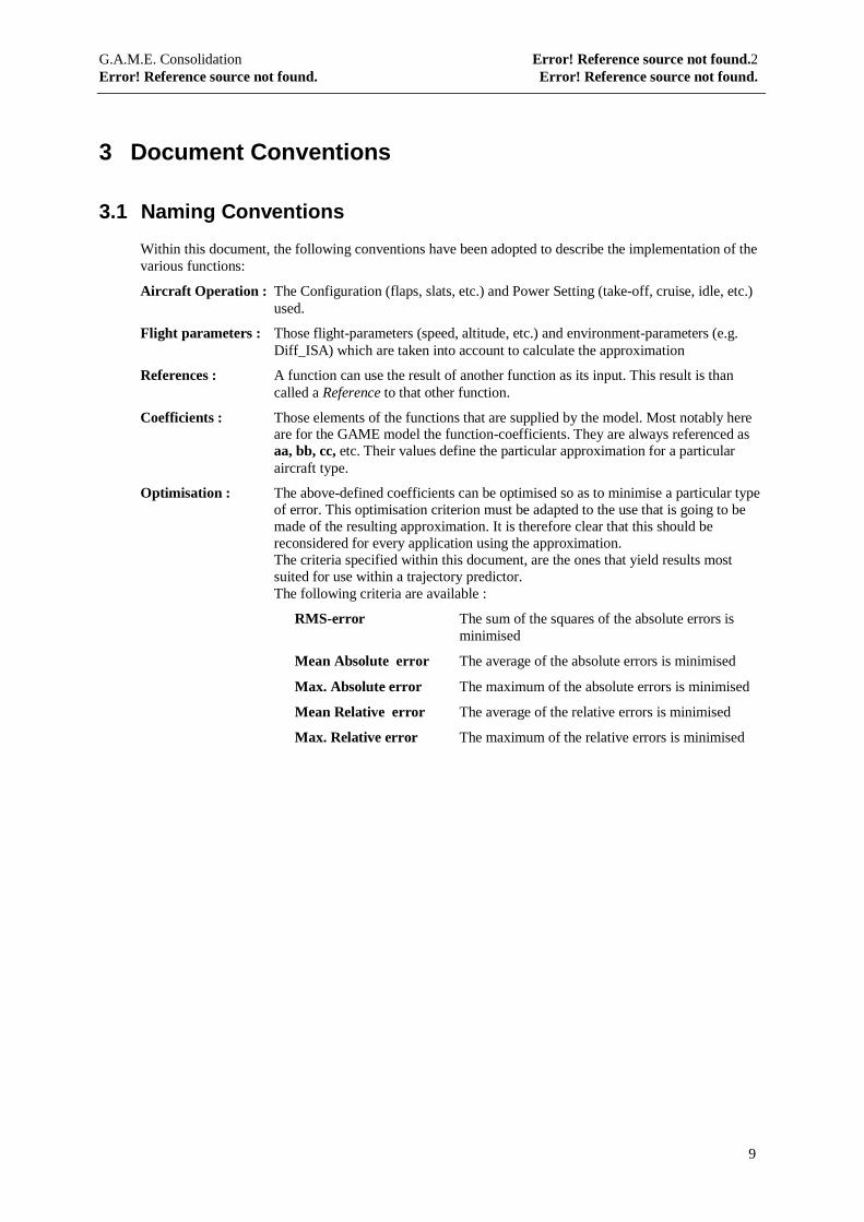
Within this document, the following conventions have been adopted to describe the implementation of thevarious functions:
Aircraft Operation : The Configuration (flaps, slats, etc.) and Power Setting (take-off, cruise, idle, etc.)used.
Flight parameters : Those flight-parameters (speed, altitude, etc.) and environment-parameters (e.g.Diff_ISA) which are taken into account to calculate the approximation
References : A function can use the result of another function as its input. This result is thancalled a Reference to that other function.
Coefficients : Those elements of the functions that are supplied by the model. Most notably hereare for the GAME model the function-coefficients. They are always referenced asaa, bb, cc, etc. Their values define the particular approximation for a particularaircraft type.
Optimisation : The above-defined coefficients can be optimised so as to minimise a particular typeof error. This optimisation criterion must be adapted to the use that is going to bemade of the resulting approximation. It is therefore clear that this should bereconsidered for every application using the approximation.The criteria specified within this document, are the ones that yield results mostsuited for use within a trajectory predictor.The following criteria are available :
RMS-error The sum of the squares of the absolute errors isminimised
Mean Absolute error The average of the absolute errors is minimised
Max. Absolute error The maximum of the absolute errors is minimised
Mean Relative error The average of the relative errors is minimised
Max. Relative error The maximum of the relative errors is minimised
G.A.M.E. Consolidation Error! Reference source not found.2Error! Reference source not found. Error! Reference source not found.
10
3.2 Definitions and Units used
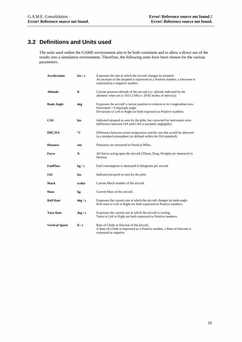
The units used within the GAME-environment aim to be both consistent and to allow a direct use of theresults into a simulation environment. Therefore, the following units have been chosen for the variousparameters.
Acceleration kts / s Expresses the rate at which the aircraft changes its airspeedAn increase of the airspeed is expressed as a Positive number; a Decrease isexpressed as a negative number.
Altitude ft Current pressure-altitude of the aircraft (i.e. altitude indicated by thealtimeter when set to 1013.2 hPa (= 29.92 inches of mercury)
Bank Angle deg Expresses the aircraft’s current position in relation to its Longitudinal axis.Horizontal = 0 deg bank-angleDeviations to Left or Right are both expressed as Positive numbers.
CAS kts Indicated airspeed as seen by the pilot, but corrected for instrument error.(difference between IAS and CAS is normally negligible).
Diff_ISA °C Difference between actual temperature and the one that would be observedin a standard atmosphere (as defined within the ISA standard).
Distance nm Distances are measured in Nautical Miles.
Force N All forces acting upon the aircraft (Thrust, Drag, Weight) are measured inNewton.
FuelFlow kg / s Fuel consumption is measured in kilograms per second
IAS kts Indicated airspeed as seen by the pilot.
Mach scalar Current Mach-number of the aircraft.
Mass kg Current Mass of the aircraft.
Roll Rate deg / s Expresses the current rate at which the aircraft changes its bank-angleRoll-rates to Left or Right are both expressed as Positive numbers.
Turn Rate deg / s Expresses the current rate at which the aircraft is turningTurns to Left or Right are both expressed as Positive numbers.
Vertical Speed ft / s Rate of Climb or Descent of the aircraft.A Rate-of-Climb is expressed as a Positive number, a Rate-of-Descent isexpressed as negative
G.A.M.E. Consolidation Error! Reference source not found.2Error! Reference source not found. Error! Reference source not found.
11
4 Aircraft Type Categories
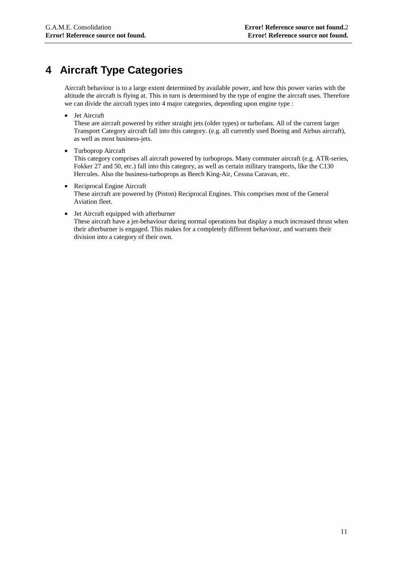
Aircraft behaviour is to a large extent determined by available power, and how this power varies with thealtitude the aircraft is flying at. This in turn is determined by the type of engine the aircraft uses. Thereforewe can divide the aircraft types into 4 major categories, depending upon engine type :
• Jet AircraftThese are aircraft powered by either straight jets (older types) or turbofans. All of the current largerTransport Category aircraft fall into this category. (e.g. all currently used Boeing and Airbus aircraft),as well as most business-jets.
• Turboprop AircraftThis category comprises all aircraft powered by turboprops. Many commuter aircraft (e.g. ATR-series,Fokker 27 and 50, etc.) fall into this category, as well as certain military transports, like the C130Hercules. Also the business-turboprops as Beech King-Air, Cessna Caravan, etc.
• Reciprocal Engine AircraftThese aircraft are powered by (Piston) Reciprocal Engines. This comprises most of the GeneralAviation fleet.
• Jet Aircraft equipped with afterburnerThese aircraft have a jet-behaviour during normal operations but display a much increased thrust whentheir afterburner is engaged. This makes for a completely different behaviour, and warrants theirdivision into a category of their own.
G.A.M.E. Consolidation Error! Reference source not found.2Error! Reference source not found. Error! Reference source not found.
12
5 Flight Phases
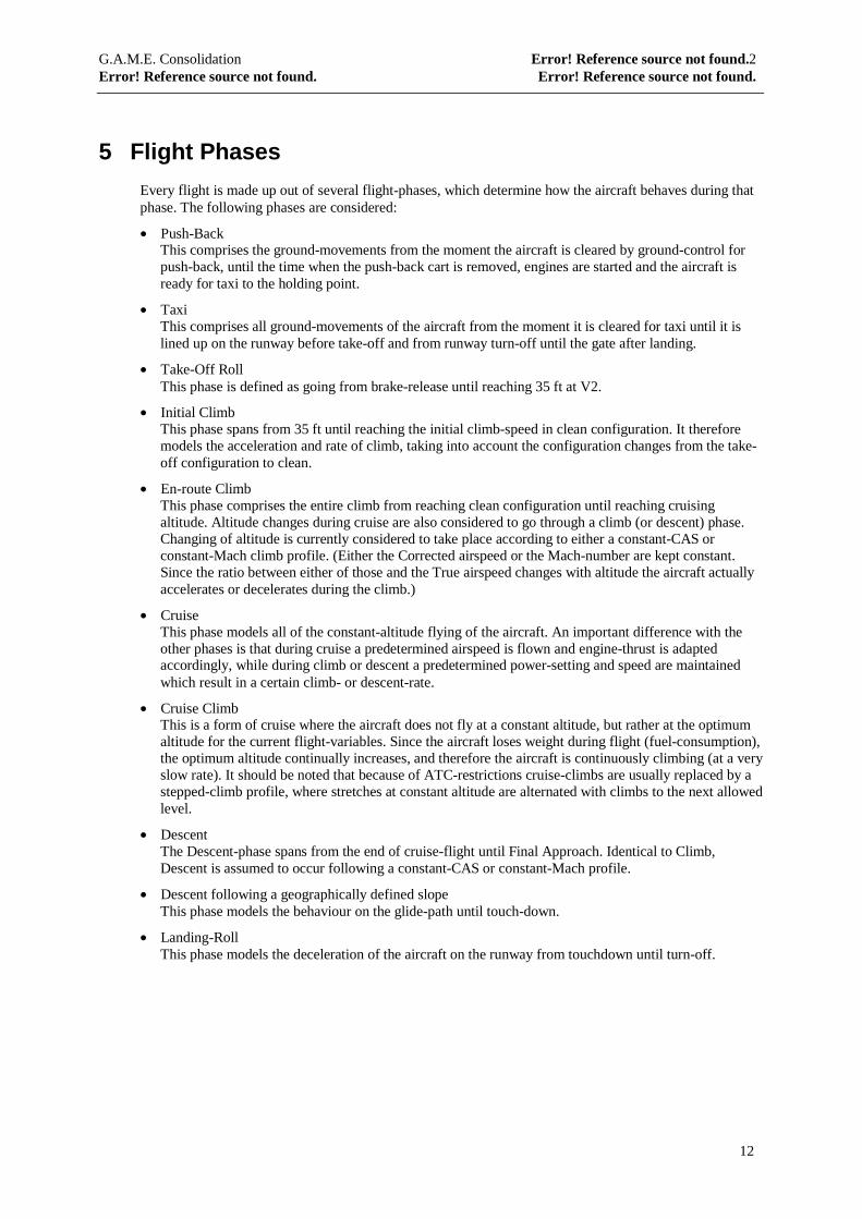
Every flight is made up out of several flight-phases, which determine how the aircraft behaves during thatphase. The following phases are considered:
• Push-BackThis comprises the ground-movements from the moment the aircraft is cleared by ground-control forpush-back, until the time when the push-back cart is removed, engines are started and the aircraft isready for taxi to the holding point.
• TaxiThis comprises all ground-movements of the aircraft from the moment it is cleared for taxi until it islined up on the runway before take-off and from runway turn-off until the gate after landing.
• Take-Off RollThis phase is defined as going from brake-release until reaching 35 ft at V2.
• Initial ClimbThis phase spans from 35 ft until reaching the initial climb-speed in clean configuration. It thereforemodels the acceleration and rate of climb, taking into account the configuration changes from the take-off configuration to clean.
• En-route ClimbThis phase comprises the entire climb from reaching clean configuration until reaching cruisingaltitude. Altitude changes during cruise are also considered to go through a climb (or descent) phase.Changing of altitude is currently considered to take place according to either a constant-CAS orconstant-Mach climb profile. (Either the Corrected airspeed or the Mach-number are kept constant.Since the ratio between either of those and the True airspeed changes with altitude the aircraft actuallyaccelerates or decelerates during the climb.)
• CruiseThis phase models all of the constant-altitude flying of the aircraft. An important difference with theother phases is that during cruise a predetermined airspeed is flown and engine-thrust is adaptedaccordingly, while during climb or descent a predetermined power-setting and speed are maintainedwhich result in a certain climb- or descent-rate.
• Cruise ClimbThis is a form of cruise where the aircraft does not fly at a constant altitude, but rather at the optimumaltitude for the current flight-variables. Since the aircraft loses weight during flight (fuel-consumption),the optimum altitude continually increases, and therefore the aircraft is continuously climbing (at a veryslow rate). It should be noted that because of ATC-restrictions cruise-climbs are usually replaced by astepped-climb profile, where stretches at constant altitude are alternated with climbs to the next allowedlevel.
• DescentThe Descent-phase spans from the end of cruise-flight until Final Approach. Identical to Climb,Descent is assumed to occur following a constant-CAS or constant-Mach profile.
• Descent following a geographically defined slopeThis phase models the behaviour on the glide-path until touch-down.
• Landing-RollThis phase models the deceleration of the aircraft on the runway from touchdown until turn-off.
G.A.M.E. Consolidation Error! Reference source not found.2Error! Reference source not found. Error! Reference source not found.
13
6 Configurations
6.1 High-Lift Devices
Different Flight phases pose different requirements on the aircraft’s aerodynamic characteristics. Forcruise, the Drag must be kept as low as possible for the design cruise speed (to lower fuel consumption).For approach and landing on the other hand, the goal is to keep the minimum airspeed as low as possible(to reduce runway requirements).
Therefore, depending upon the phase of flight, aircraft deploy or retract high-lift devices, such that theiraerodynamic characteristics match as well as possible the requirements for that phase. Since theseconfiguration-changes greatly influence the aircraft’s performance, there is a need to model the behaviourfor each of these configurations separately.
Every Configuration defined by the manufacturer is specified in the database, but at least the followingshould always be present :
• Clean Flaps and slats retracted = En-route configuration
• Take-Off Flaps and slats set in recommended Take-Off position
• Approach Flaps and slats set in recommended position for Approach
• Landing Flaps and slats set in recommended position for Landing
During flight the aircraft changes its configuration according to one of 2 schedules :
TakeOff Schedule Flaps/Slats are retracted from the TakeOff-configuration to Clean Configuration withpossibly various intermediate settings.
Landing Schedule Flaps/Slats are extended from Clean to Landing-Configuration with possibly variousintermediate settings.
For each of these schedules we need the following information :
• Configurations used
• Scheduled order
For each of the configurations in the TakeOff schedule we need the following information :
• Name Identifies the configuration
• Retraction CAS At which speed is the configuration changed to the next in the TakeOffschedule
• Retraction time How long does it take to change to the next configuration
For each of the configurations in the Landing schedule we need the following information :
• Name Identifies the configuration
• Extension CAS At which speed is the configuration changed to the next in the Landingschedule
• Extension time How long does it take to change to the next configuration
G.A.M.E. Consolidation Error! Reference source not found.2Error! Reference source not found. Error! Reference source not found.
14
6.2 Drag Devices
In addition to the high-lift devices, most aircraft also possess devices to create supplementary drag. This inorder to be able to reduce speed quickly or to be able to fly a steeper descent-path without increasingairspeed.
Although their main purpose is different, we will also categorise Landing Gear under this heading, sincefrom a modelling point of view, extending the gear purely adds drag to the airframe.
In view of these, the following two items are defined in this category :
• Speed-brakes
• Landing Gear
6.3 Other devices with influence on Performance
This is a category of devices that do not directly change airframe behaviour, but use some of the availableengine power, and therefor influence performance in the vertical plane, as well as fuel consumption. Thefollowing devices are identified :
• Anti-Ice systems
• Air Conditioning
G.A.M.E. Consolidation Error! Reference source not found.2Error! Reference source not found. Error! Reference source not found.
15
7 Engine Specifics
Power output of an engine is dependent upon (among others) temperature and altitude. In the case of jetengines, power output declines with increasing temperature and altitude, or, if one looks at it the other wayaround, increases with diminishing temperature and altitude. Usually however, there is a limit temperatureand a limit altitude below which the engine’s power output no longer increases, but remains constant. Thisis called ‘Flat rating’ of the engine. The temperature and altitude at which this phenomenon occurs will becalled the Flat_rate_ISA (temperature being expressed as a difference between actual temperature andstandard atmosphere) and Flat_rate_Altitude.
These items must be defined for each aircraft type. They can be determined by analysing the Vertical-speedat climb-power in function of Altitude and ISA. If flat-rating occurs, these curves will show a clear bend atthe flat-rating point.
Flat-rating can occur as one of the following:
• Completely distinct temperature flat-rating and altitude flat-rating. This means that flat-rating fortemperature and altitude are independent of one-another, and can both be described as a single value.This implies that 4 different zones can be defined for the Vertical-speed functions
• Altitude and temperature flat-rating are inter-dependent. This means that only 2 different-zones mustbe defined (below and above flat-rating), but we must define the function that determines whether aparticular combination of altitude and temperature lies below or above flat-rating. If this behaviour isobserved, we will specify it by stating that there is no flat-rate ISA, and by determining a formula thatcalculates the flat-rate altitude as a function of the actual Diff_ISA.
To summarise, the following cases can be observed, and each requires the definition of specific items
1. No Flat_rate_ISA or Flat_rate_Altitude are observed
2. Only a Flat_rate_ISA is observed
3. Only a Flat_rate_Altitude is observed
4. Independent Flat_rate_ISA and Flat_rate_Altitude are observed
5. Flat_rate_ISA and Flat_rate_Altitude are inter-dependent
7.1 No Flat-rating
If no Flat-rating is observed, then obviously no items are required to describe it.
G.A.M.E. Consolidation Error! Reference source not found.2Error! Reference source not found. Error! Reference source not found.
16
7.2 Only ISA Flat-rating
This requires the following elements:
7.2.1 Flat-rate Diff_ISA
Temperature below which power output no longer varies with temperature.
Item type Flat_rate_ISA
Unit ° C difference between actual temperature and that in a standardatmosphere
Configuration Independent from Aircraft configuration
Power setting Climb
API n/a
7.2.1.1 GAME Implementation
Flat-rating for jet-engines typically occurs at a specific Diff_ISA.
Flat_rate_ISA = cst
7.2.1.2 BADA-implementation
Flat_rate_ISA = CTc,4
Coefficients : CTc,4 °C difference between actual temperature and standard atmosphere
7.3 Only Altitude Flat-rating
This requires the following elements:
7.3.1 Flat-rate Altitude
Altitude below which power output does not vary with altitude.
Item type Flat_rate_Altitude
Unit ft
Configuration Independent from Aircraft configuration
Power setting Climb
API n/a
7.3.1.1 GAME Implementation
Flat-rating for jet-engines typically occurs at a specific Altitude.
Flat_rate_Altitude = cst
G.A.M.E. Consolidation Error! Reference source not found.2Error! Reference source not found. Error! Reference source not found.
17
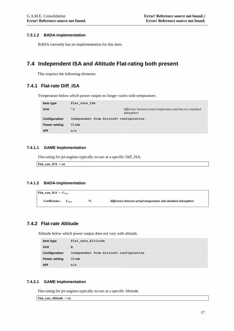
7.3.1.2 BADA-implementation
BADA currently has no implementation for this item.
7.4 Independent ISA and Altitude Flat-rating both present
This requires the following elements:
7.4.1 Flat-rate Diff_ISA
Temperature below which power output no longer varies with temperature.
Item type Flat_rate_ISA
Unit ° C difference between actual temperature and that in a standardatmosphere
Configuration Independent from Aircraft configuration
Power setting Climb
API n/a
7.4.1.1 GAME Implementation
Flat-rating for jet-engines typically occurs at a specific Diff_ISA.
Flat_rate_ISA = cst
7.4.1.2 BADA-implementation
Flat_rate_ISA = CTc,4
Coefficients : CTc,4 °C difference between actual temperature and standard atmosphere
7.4.2 Flat-rate Altitude
Altitude below which power output does not vary with altitude.
Item type Flat_rate_Altitude
Unit ft
Configuration Independent from Aircraft configuration
Power setting Climb
API n/a
7.4.2.1 GAME Implementation
Flat-rating for jet-engines typically occurs at a specific Altitude.
Flat_rate_Altitude = cst
G.A.M.E. Consolidation Error! Reference source not found.2Error! Reference source not found. Error! Reference source not found.
18
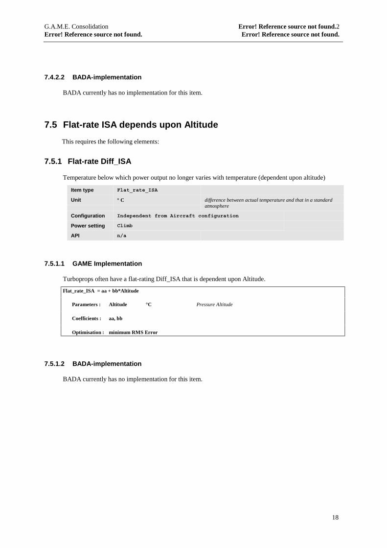
7.4.2.2 BADA-implementation
BADA currently has no implementation for this item.
7.5 Flat-rate ISA depends upon Altitude
This requires the following elements:
7.5.1 Flat-rate Diff_ISA
Temperature below which power output no longer varies with temperature (dependent upon altitude)
Item type Flat_rate_ISA
Unit ° C difference between actual temperature and that in a standardatmosphere
Configuration Independent from Aircraft configuration
Power setting Climb
API n/a
7.5.1.1 GAME Implementation
Turboprops often have a flat-rating Diff_ISA that is dependent upon Altitude.
Flat_rate_ISA = aa + bb*Altitude
Parameters : Altitude °C Pressure Altitude
Coefficients : aa, bb
Optimisation : minimum RMS Error
7.5.1.2 BADA-implementation
BADA currently has no implementation for this item.
G.A.M.E. Consolidation Error! Reference source not found.2Error! Reference source not found. Error! Reference source not found.
19
8 Basic Formulas
8.1 GAME
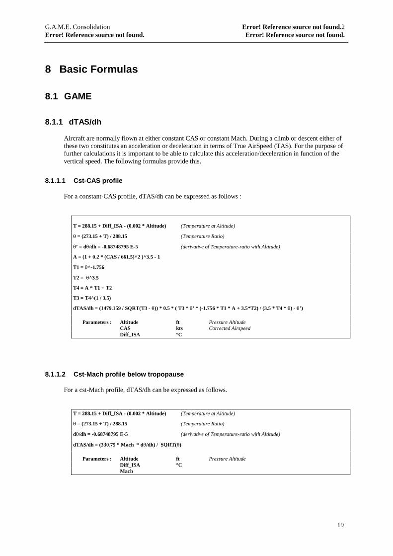
8.1.1 dTAS/dh
Aircraft are normally flown at either constant CAS or constant Mach. During a climb or descent either ofthese two constitutes an acceleration or deceleration in terms of True AirSpeed (TAS). For the purpose offurther calculations it is important to be able to calculate this acceleration/deceleration in function of thevertical speed. The following formulas provide this.
8.1.1.1 Cst-CAS profile
For a constant-CAS profile, dTAS/dh can be expressed as follows :
T = 288.15 + Diff_ISA - (0.002 * Altitude) (Temperature at Altitude)
θ = (273.15 + T) / 288.15 (Temperature Ratio)
θ’ = dθ/dh = -0.68748795 E-5 (derivative of Temperature-ratio with Altitude)
A = (1 + 0.2 * (CAS / 661.5)^2 )^3.5 - 1
T1 = θ^-1.756
T2 = θ^3.5
T4 = A * T1 + T2
T3 = T4^(1 / 3.5)
dTAS/dh = (1479.159 / SQRT(T3 - θ)) * 0.5 * ( T3 * θ’ * (-1.756 * T1 * A + 3.5*T2) / (3.5 * T4 * θ) - θ’)
Parameters : Altitude ft Pressure AltitudeCAS kts Corrected AirspeedDiff_ISA °C
8.1.1.2 Cst-Mach profile below tropopause
For a cst-Mach profile, dTAS/dh can be expressed as follows.
T = 288.15 + Diff_ISA - (0.002 * Altitude) (Temperature at Altitude)
θ = (273.15 + T) / 288.15 (Temperature Ratio)
dθ/dh = -0.68748795 E-5 (derivative of Temperature-ratio with Altitude)
dTAS/dh = (330.75 * Mach * dθ/dh) / SQRT(θ)
Parameters : Altitude ft Pressure AltitudeDiff_ISA °CMach
G.A.M.E. Consolidation Error! Reference source not found.2Error! Reference source not found. Error! Reference source not found.
20
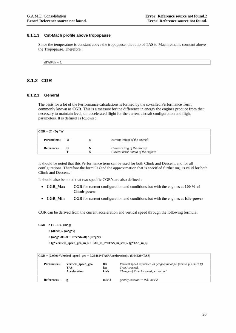
8.1.1.3 Cst-Mach profile above tropopause
Since the temperature is constant above the tropopause, the ratio of TAS to Mach remains constant abovethe Tropopause. Therefore :
dTAS/dh = 0.
8.1.2 CGR
8.1.2.1 General
The basis for a lot of the Performance calculations is formed by the so-called Performance Term,commonly known as CGR. This is a measure for the difference in energy the engines produce from thatnecessary to maintain level, un-accelerated flight for the current aircraft configuration and flight-parameters. It is defined as follows :
CGR = (T - D) / W
Parameters : W N current weight of the aircraft
References : D N Current Drag of the aircraftT N Current hrust-output of the engines
It should be noted that this Performance term can be used for both Climb and Descent, and for allconfigurations. Therefore the formula (and the approximation that is specified further on), is valid for bothClimb and Descent.
It should also be noted that two specific CGR’s are also defined :
• CGR_Max CGR for current configuration and conditions but with the engines at 100 % ofClimb-power
• CGR_Min CGR for current configuration and conditions but with the engines at Idle-power
CGR can be derived from the current acceleration and vertical speed through the following formula :
CGR = (T – D) / (m*g)
= (dE/dt ) / (m*g*v)
= (m*g* dH/dt + m*v*dv/dt) / (m*g*v)
= (g*Vertical_speed_geo_m_s + TAS_m_s*dTAS_m_s/dt) / (g*TAS_m_s)
CGR = (2.9901*Vertical_speed_geo + 0.26461*TAS*Acceleration) / (5.04626*TAS)
Parameters : Vertical_speed_geo ft/s Vertical speed expressed as geographical ft/s (versus pressure ft)TAS kts True Airspeed.Acceleration kts/s Change of True Airspeed per second
References : g m/s^2 gravity constant = 9.81 m/s^2
G.A.M.E. Consolidation Error! Reference source not found.2Error! Reference source not found. Error! Reference source not found.
21
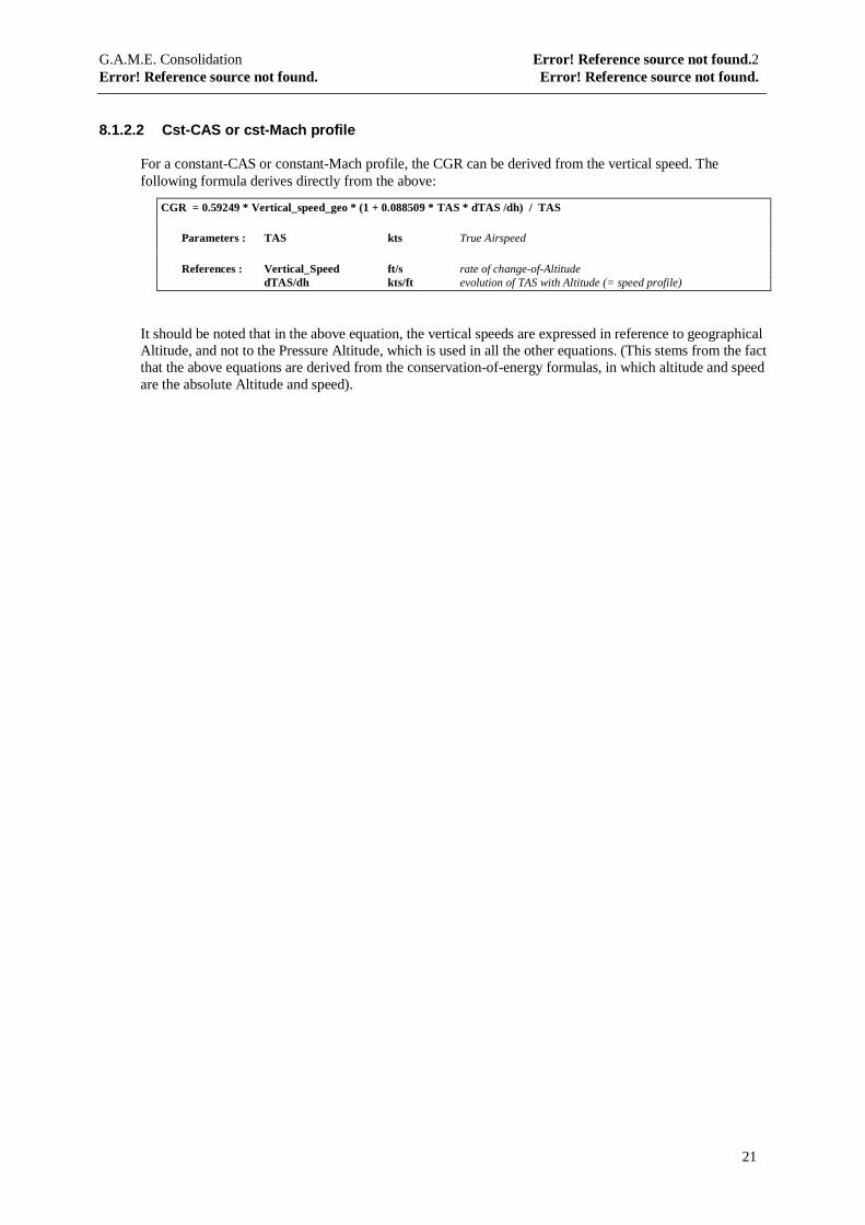
8.1.2.2 Cst-CAS or cst-Mach profile
For a constant-CAS or constant-Mach profile, the CGR can be derived from the vertical speed. Thefollowing formula derives directly from the above:
CGR = 0.59249 * Vertical_speed_geo * (1 + 0.088509 * TAS * dTAS /dh) / TAS
Parameters : TAS kts True Airspeed
References : Vertical_Speed ft/s rate of change-of-AltitudedTAS/dh kts/ft evolution of TAS with Altitude (= speed profile)
It should be noted that in the above equation, the vertical speeds are expressed in reference to geographicalAltitude, and not to the Pressure Altitude, which is used in all the other equations. (This stems from the factthat the above equations are derived from the conservation-of-energy formulas, in which altitude and speedare the absolute Altitude and speed).
G.A.M.E. Consolidation Error! Reference source not found.2Error! Reference source not found. Error! Reference source not found.
22
8.2 BADA
Several of the BADA-functions use BADA-specified Thrust and Drag calculations. To avoid repeatingthose in every one of the pertaining paragraphs, they are explained here in advance.
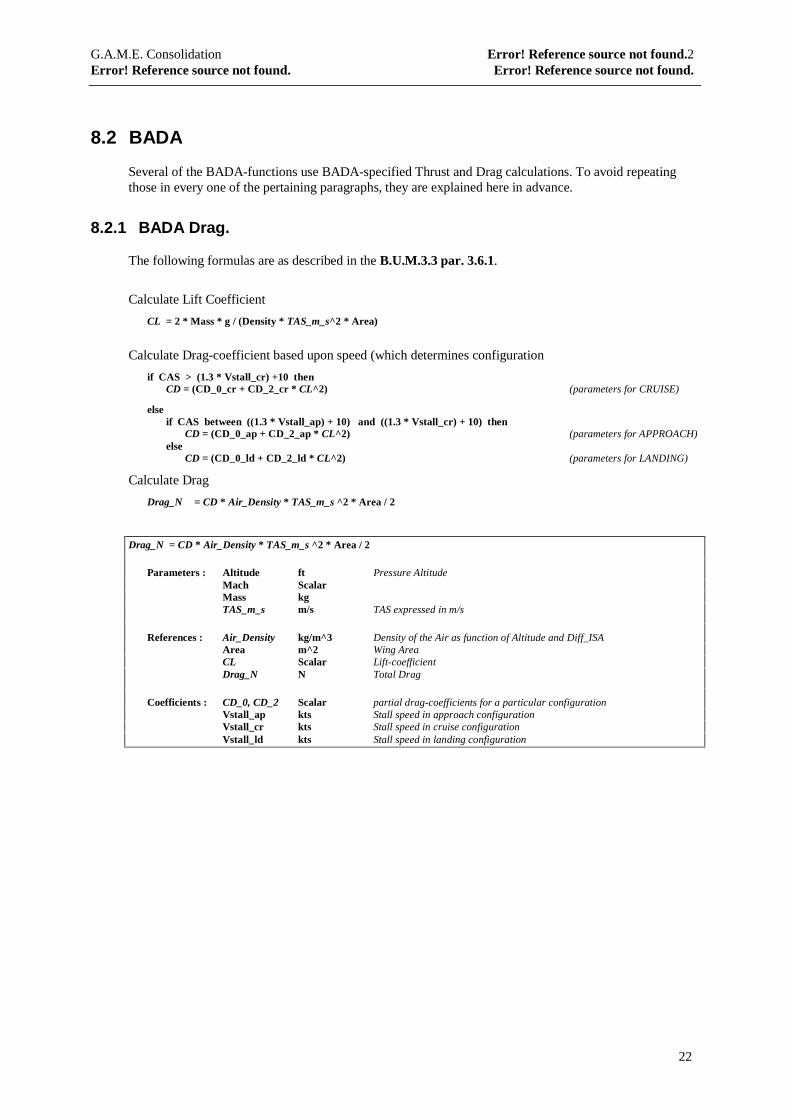
8.2.1 BADA Drag.
The following formulas are as described in the B.U.M.3.3 par. 3.6.1.
Calculate Lift Coefficient
CL = 2 * Mass * g / (Density * TAS_m_s^2 * Area)
Calculate Drag-coefficient based upon speed (which determines configuration
if CAS > (1.3 * Vstall_cr) +10 thenCD = (CD_0_cr + CD_2_cr * CL^2) (parameters for CRUISE)
elseif CAS between ((1.3 * Vstall_ap) + 10) and ((1.3 * Vstall_cr) + 10) then
CD = (CD_0_ap + CD_2_ap * CL^2) (parameters for APPROACH)else
CD = (CD_0_ld + CD_2_ld * CL^2) (parameters for LANDING)
Calculate Drag
Drag_N = CD * Air_Density * TAS_m_s ^2 * Area / 2
Drag_N = CD * Air_Density * TAS_m_s ^2 * Area / 2
Parameters : Altitude ft Pressure AltitudeMach ScalarMass kgTAS_m_s m/s TAS expressed in m/s
References : Air_Density kg/m^3 Density of the Air as function of Altitude and Diff_ISAArea m^2 Wing AreaCL Scalar Lift-coefficientDrag_N N Total Drag
Coefficients : CD_0, CD_2 Scalar partial drag-coefficients for a particular configurationVstall_ap kts Stall speed in approach configurationVstall_cr kts Stall speed in cruise configurationVstall_ld kts Stall speed in landing configuration
G.A.M.E. Consolidation Error! Reference source not found.2Error! Reference source not found. Error! Reference source not found.
23
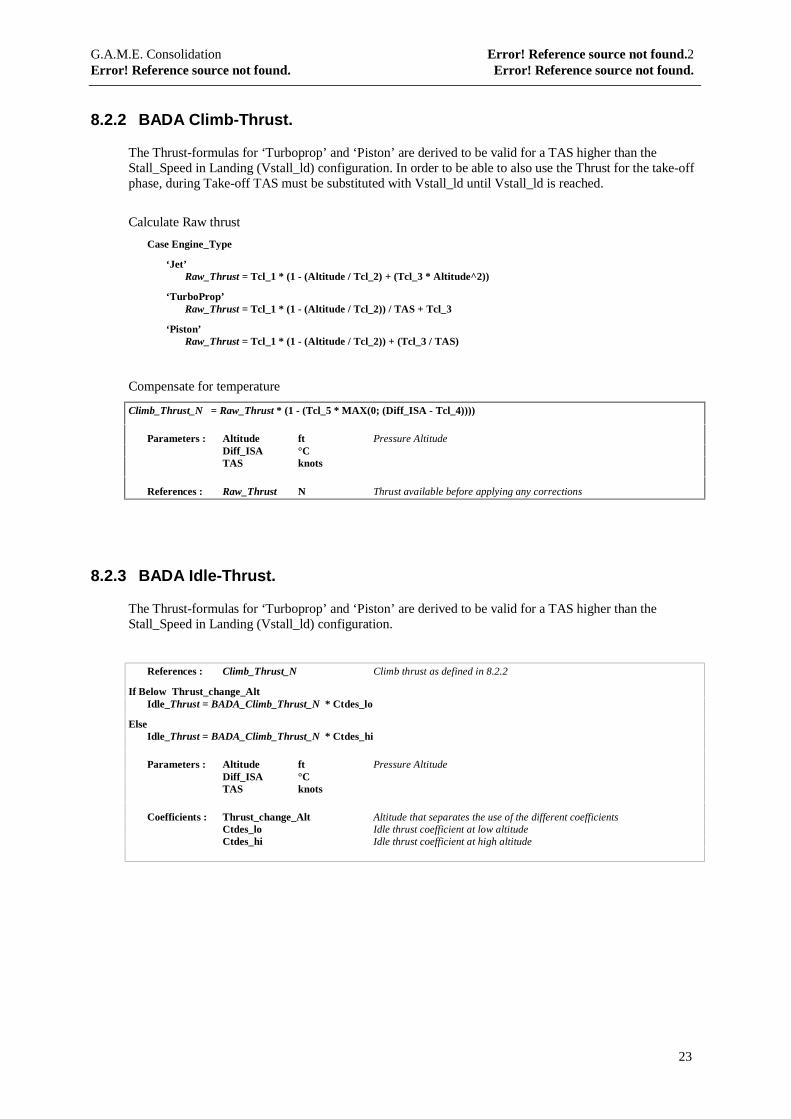
8.2.2 BADA Climb-Thrust.
The Thrust-formulas for ‘Turboprop’ and ‘Piston’ are derived to be valid for a TAS higher than theStall_Speed in Landing (Vstall_ld) configuration. In order to be able to also use the Thrust for the take-offphase, during Take-off TAS must be substituted with Vstall_ld until Vstall_ld is reached.
Calculate Raw thrust
Case Engine_Type
‘Jet’Raw_Thrust = Tcl_1 * (1 - (Altitude / Tcl_2) + (Tcl_3 * Altitude^2))
‘TurboProp’Raw_Thrust = Tcl_1 * (1 - (Altitude / Tcl_2)) / TAS + Tcl_3
‘Piston’Raw_Thrust = Tcl_1 * (1 - (Altitude / Tcl_2)) + (Tcl_3 / TAS)
Compensate for temperature
Climb_Thrust_N = Raw_Thrust * (1 - (Tcl_5 * MAX(0; (Diff_ISA - Tcl_4))))
Parameters : Altitude ft Pressure AltitudeDiff_ISA °CTAS knots
References : Raw_Thrust N Thrust available before applying any corrections
8.2.3 BADA Idle-Thrust.
The Thrust-formulas for ‘Turboprop’ and ‘Piston’ are derived to be valid for a TAS higher than theStall_Speed in Landing (Vstall_ld) configuration.
References : Climb_Thrust_N Climb thrust as defined in 8.2.2
If Below Thrust_change_AltIdle_Thrust = BADA_Climb_Thrust_N * Ctdes_lo
ElseIdle_Thrust = BADA_Climb_Thrust_N * Ctdes_hi
Parameters : Altitude ft Pressure AltitudeDiff_ISA °CTAS knots
Coefficients : Thrust_change_Alt Altitude that separates the use of the different coefficientsCtdes_lo Idle thrust coefficient at low altitudeCtdes_hi Idle thrust coefficient at high altitude
G.A.M.E. Consolidation Error! Reference source not found.2Error! Reference source not found. Error! Reference source not found.
24
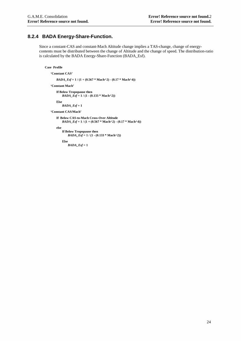
8.2.4 BADA Energy-Share-Function.
Since a constant-CAS and constant-Mach Altitude change implies a TAS-change, change of energy-contents must be distributed between the change of Altitude and the change of speed. The distribution-ratiois calculated by the BADA Energy-Share-Function (BADA_Esf).
Case Profile
‘Constant CAS’
BADA_Esf = 1 / (1 + (0.567 * Mach^2) - (0.17 * Mach^4))
‘Constant Mach’
If Below Tropopause thenBADA_Esf = 1 / (1 - (0.133 * Mach^2))
ElseBADA_Esf = 1
‘Constant CAS/Mach’
If Below CAS-to-Mach Cross-Over AltitudeBADA_Esf = 1 / (1 + (0.567 * Mach^2) - (0.17 * Mach^4))
elseIf Below Tropopause then
BADA_Esf = 1 / (1 - (0.133 * Mach^2))
ElseBADA_Esf = 1
G.A.M.E. Consolidation Error! Reference source not found.2Error! Reference source not found. Error! Reference source not found.
25
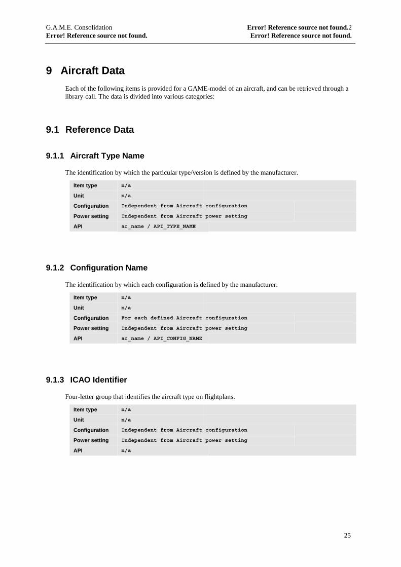
9 Aircraft Data
Each of the following items is provided for a GAME-model of an aircraft, and can be retrieved through alibrary-call. The data is divided into various categories:
9.1 Reference Data
9.1.1 Aircraft Type Name
The identification by which the particular type/version is defined by the manufacturer.
Item type n/a
Unit n/a
Configuration Independent from Aircraft configuration
Power setting Independent from Aircraft power setting
API ac_name / API_TYPE_NAME
9.1.2 Configuration Name
The identification by which each configuration is defined by the manufacturer.
Item type n/a
Unit n/a
Configuration For each defined Aircraft configuration
Power setting Independent from Aircraft power setting
API ac_name / API_CONFIG_NAME
9.1.3 ICAO Identifier
Four-letter group that identifies the aircraft type on flightplans.
Item type n/a
Unit n/a
Configuration Independent from Aircraft configuration
Power setting Independent from Aircraft power setting
API n/a

G.A.M.E. Consolidation Error! Reference source not found.2Error! Reference source not found. Error! Reference source not found.
26
9.2 General Information
9.2.1 Aircraft Category
Specifies the aircraft Category, mainly determined by the Engine type of the aircraft. It is defined by a codebelonging to one of the following:
• Jet• Turboprop• Piston• Jet with Afterburner
Item type n/a
Unit n/a
Categories n/a
Configuration Independent from Aircraft configuration
Power setting Independent from Aircraft power setting
API model / API_ENGINE_TYPE
9.2.2 Number of Engines
Number of engines used on the aircraft
Item type n/a
Unit n/a
Categories Applicable to All Aircraft categories
Configuration Independent from Aircraft configuration
Power setting Independent from Aircraft power setting
API model / API_NUMBER_OF_ENGINES
G.A.M.E. Consolidation Error! Reference source not found.2Error! Reference source not found. Error! Reference source not found.
27
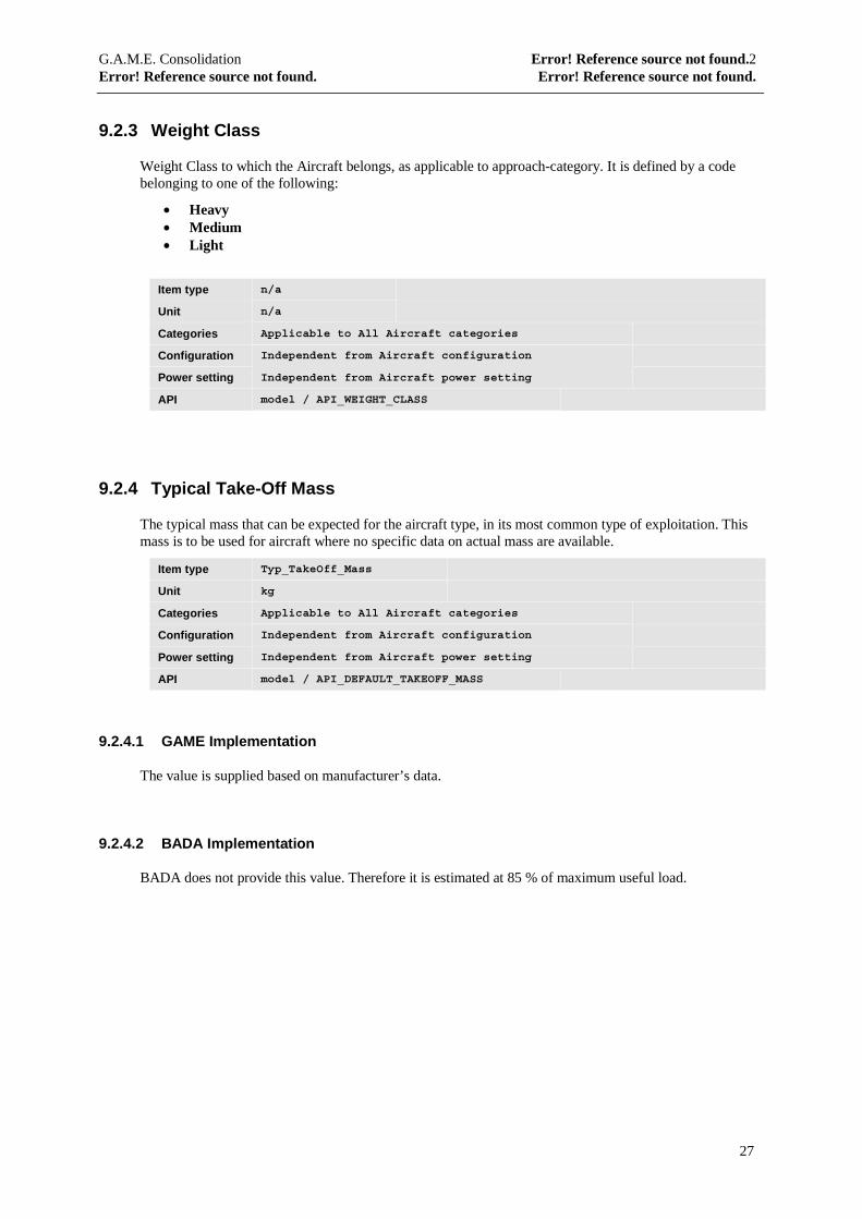
9.2.3 Weight Class
Weight Class to which the Aircraft belongs, as applicable to approach-category. It is defined by a codebelonging to one of the following:
• Heavy• Medium• Light
Item type n/a
Unit n/a
Categories Applicable to All Aircraft categories
Configuration Independent from Aircraft configuration
Power setting Independent from Aircraft power setting
API model / API_WEIGHT_CLASS
9.2.4 Typical Take-Off Mass
The typical mass that can be expected for the aircraft type, in its most common type of exploitation. Thismass is to be used for aircraft where no specific data on actual mass are available.
Item type Typ_TakeOff_Mass
Unit kg
Categories Applicable to All Aircraft categories
Configuration Independent from Aircraft configuration
Power setting Independent from Aircraft power setting
API model / API_DEFAULT_TAKEOFF_MASS
9.2.4.1 GAME Implementation
The value is supplied based on manufacturer’s data.
9.2.4.2 BADA Implementation
BADA does not provide this value. Therefore it is estimated at 85 % of maximum useful load.
G.A.M.E. Consolidation Error! Reference source not found.2Error! Reference source not found. Error! Reference source not found.
28
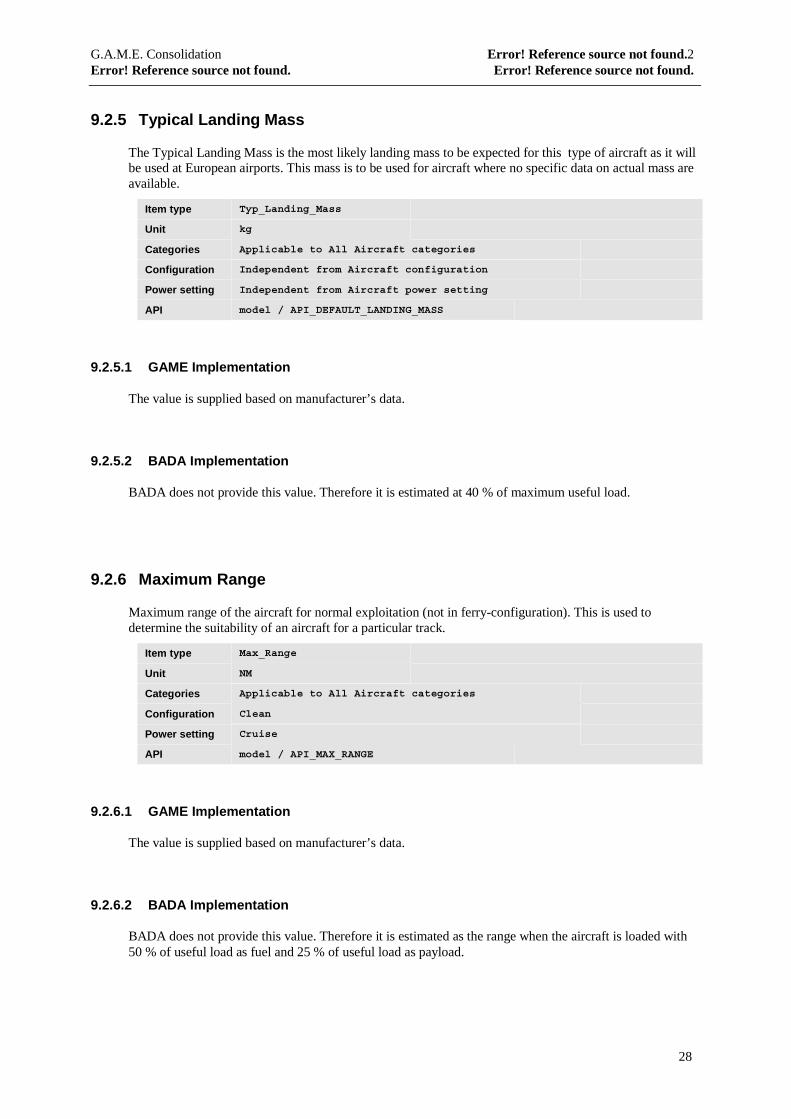
9.2.5 Typical Landing Mass
The Typical Landing Mass is the most likely landing mass to be expected for this type of aircraft as it willbe used at European airports. This mass is to be used for aircraft where no specific data on actual mass areavailable.
Item type Typ_Landing_Mass
Unit kg
Categories Applicable to All Aircraft categories
Configuration Independent from Aircraft configuration
Power setting Independent from Aircraft power setting
API model / API_DEFAULT_LANDING_MASS
9.2.5.1 GAME Implementation
The value is supplied based on manufacturer’s data.
9.2.5.2 BADA Implementation
BADA does not provide this value. Therefore it is estimated at 40 % of maximum useful load.
9.2.6 Maximum Range
Maximum range of the aircraft for normal exploitation (not in ferry-configuration). This is used todetermine the suitability of an aircraft for a particular track.
Item type Max_Range
Unit NM
Categories Applicable to All Aircraft categories
Configuration Clean
Power setting Cruise
API model / API_MAX_RANGE
9.2.6.1 GAME Implementation
The value is supplied based on manufacturer’s data.
9.2.6.2 BADA Implementation
BADA does not provide this value. Therefore it is estimated as the range when the aircraft is loaded with50 % of useful load as fuel and 25 % of useful load as payload.
G.A.M.E. Consolidation Error! Reference source not found.2Error! Reference source not found. Error! Reference source not found.
29
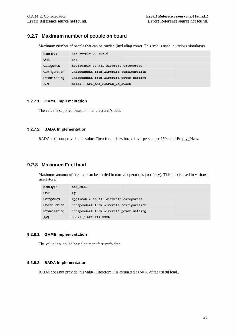
9.2.7 Maximum number of people on board
Maximum number of people that can be carried (including crew). This info is used in various simulators.
Item type Max_People_on_Board
Unit n/a
Categories Applicable to All Aircraft categories
Configuration Independent from Aircraft configuration
Power setting Independent from Aircraft power setting
API model / API_MAX_PEOPLE_ON_BOARD
9.2.7.1 GAME Implementation
The value is supplied based on manufacturer’s data.
9.2.7.2 BADA Implementation
BADA does not provide this value. Therefore it is estimated as 1 person per 250 kg of Empty_Mass.
9.2.8 Maximum Fuel load
Maximum amount of fuel that can be carried in normal operations (not ferry). This info is used in varioussimulators.
Item type Max_Fuel
Unit kg
Categories Applicable to All Aircraft categories
Configuration Independent from Aircraft configuration
Power setting Independent from Aircraft power setting
API model / API_MAX_FUEL
9.2.8.1 GAME Implementation
The value is supplied based on manufacturer’s data.
9.2.8.2 BADA Implementation
BADA does not provide this value. Therefore it is estimated as 50 % of the useful load..
G.A.M.E. Consolidation Error! Reference source not found.2Error! Reference source not found. Error! Reference source not found.
30
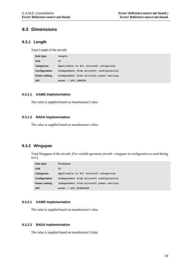
9.3 Dimensions
9.3.1 Length
Total Length of the aircraft.
Item type Length
Unit ft
Categories Applicable to All Aircraft categories
Configuration Independent from Aircraft configuration
Power setting Independent from Aircraft power setting
API model / API_LENGTH
9.3.1.1 GAME Implementation
The value is supplied based on manufacturer’s data.
9.3.1.2 BADA Implementation
The value is supplied based on manufacturer’s data.
9.3.2 Wingspan
Total Wingspan of the aircraft. (For variable-geometry aircraft : wingspan in configuration as used duringtaxi.)
Item type Wingspan
Unit ft
Categories Applicable to All Aircraft categories
Configuration Independent from Aircraft configuration
Power setting Independent from Aircraft power setting
API model / API_WINGSPAN
9.3.2.1 GAME Implementation
The value is supplied based on manufacturer’s data.
9.3.2.2 BADA Implementation
The value is supplied based on manufacturer’s data.
G.A.M.E. Consolidation Error! Reference source not found.2Error! Reference source not found. Error! Reference source not found.
31
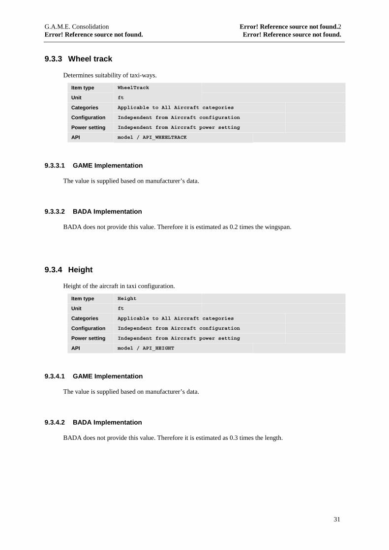
9.3.3 Wheel track
Determines suitability of taxi-ways.
Item type WheelTrack
Unit ft
Categories Applicable to All Aircraft categories
Configuration Independent from Aircraft configuration
Power setting Independent from Aircraft power setting
API model / API_WHEELTRACK
9.3.3.1 GAME Implementation
The value is supplied based on manufacturer’s data.
9.3.3.2 BADA Implementation
BADA does not provide this value. Therefore it is estimated as 0.2 times the wingspan.
9.3.4 Height
Height of the aircraft in taxi configuration.
Item type Height
Unit ft
Categories Applicable to All Aircraft categories
Configuration Independent from Aircraft configuration
Power setting Independent from Aircraft power setting
API model / API_HEIGHT
9.3.4.1 GAME Implementation
The value is supplied based on manufacturer’s data.
9.3.4.2 BADA Implementation
BADA does not provide this value. Therefore it is estimated as 0.3 times the length.
G.A.M.E. Consolidation Error! Reference source not found.2Error! Reference source not found. Error! Reference source not found.
32
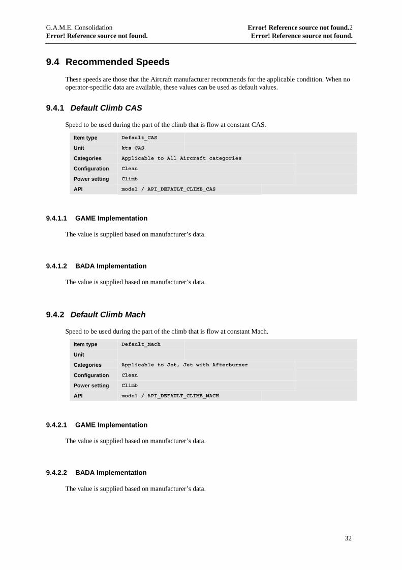
9.4 Recommended Speeds
These speeds are those that the Aircraft manufacturer recommends for the applicable condition. When nooperator-specific data are available, these values can be used as default values.
9.4.1 Default Climb CAS
Speed to be used during the part of the climb that is flow at constant CAS.
Item type Default_CAS
Unit kts CAS
Categories Applicable to All Aircraft categories
Configuration Clean
Power setting Climb
API model / API_DEFAULT_CLIMB_CAS
9.4.1.1 GAME Implementation
The value is supplied based on manufacturer’s data.
9.4.1.2 BADA Implementation
The value is supplied based on manufacturer’s data.
9.4.2 Default Climb Mach
Speed to be used during the part of the climb that is flow at constant Mach.
Item type Default_Mach
Unit
Categories Applicable to Jet, Jet with Afterburner
Configuration Clean
Power setting Climb
API model / API_DEFAULT_CLIMB_MACH
9.4.2.1 GAME Implementation
The value is supplied based on manufacturer’s data.
9.4.2.2 BADA Implementation
The value is supplied based on manufacturer’s data.
G.A.M.E. Consolidation Error! Reference source not found.2Error! Reference source not found. Error! Reference source not found.
33
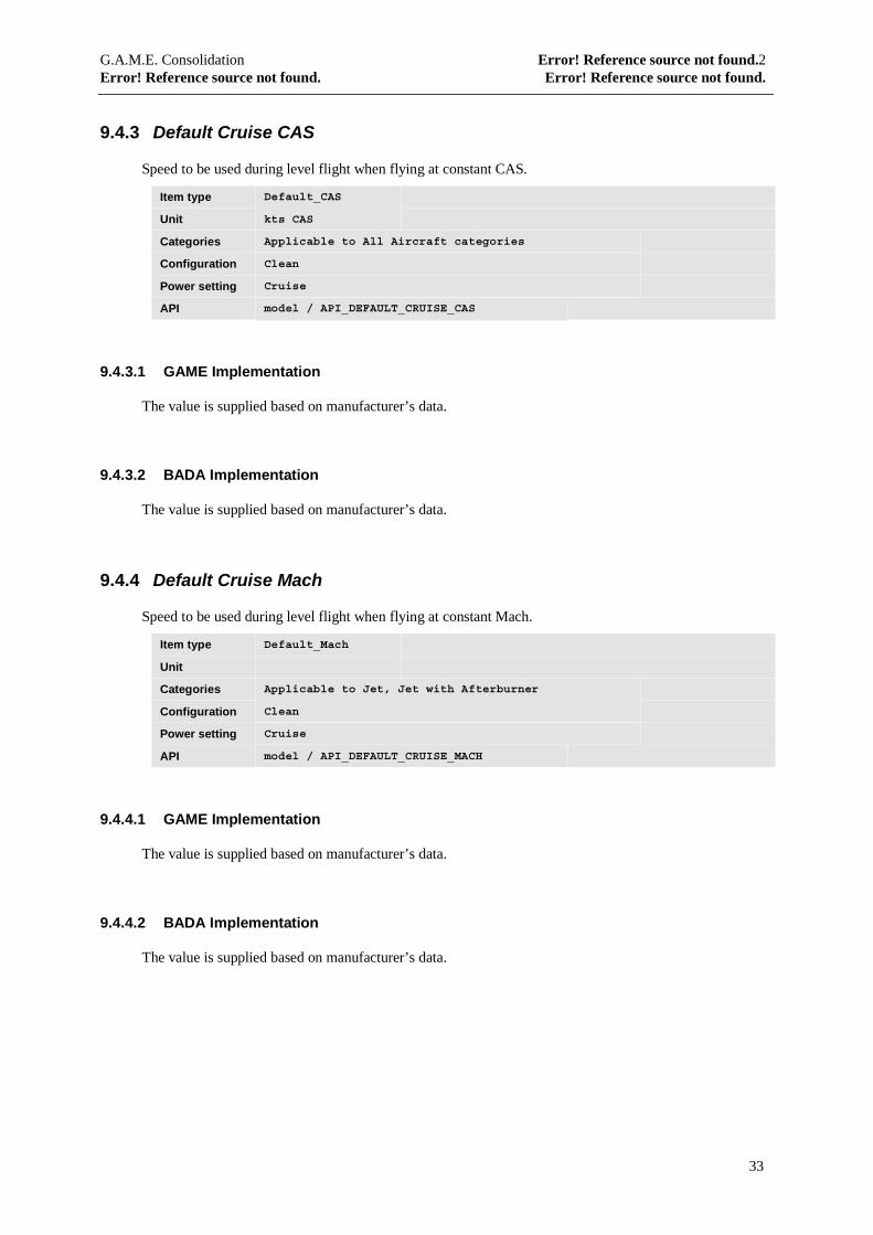
9.4.3 Default Cruise CAS
Speed to be used during level flight when flying at constant CAS.
Item type Default_CAS
Unit kts CAS
Categories Applicable to All Aircraft categories
Configuration Clean
Power setting Cruise
API model / API_DEFAULT_CRUISE_CAS
9.4.3.1 GAME Implementation
The value is supplied based on manufacturer’s data.
9.4.3.2 BADA Implementation
The value is supplied based on manufacturer’s data.
9.4.4 Default Cruise Mach
Speed to be used during level flight when flying at constant Mach.
Item type Default_Mach
Unit
Categories Applicable to Jet, Jet with Afterburner
Configuration Clean
Power setting Cruise
API model / API_DEFAULT_CRUISE_MACH
9.4.4.1 GAME Implementation
The value is supplied based on manufacturer’s data.
9.4.4.2 BADA Implementation
The value is supplied based on manufacturer’s data.
G.A.M.E. Consolidation Error! Reference source not found.2Error! Reference source not found. Error! Reference source not found.
34
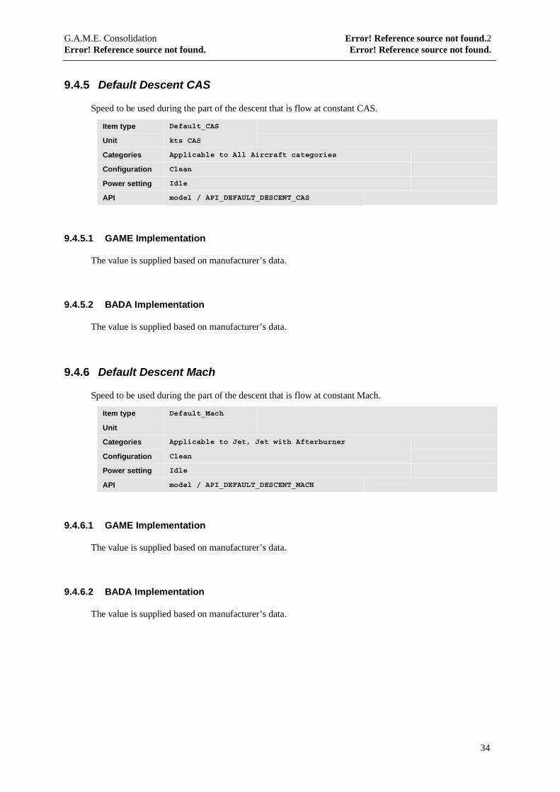
9.4.5 Default Descent CAS
Speed to be used during the part of the descent that is flow at constant CAS.
Item type Default_CAS
Unit kts CAS
Categories Applicable to All Aircraft categories
Configuration Clean
Power setting Idle
API model / API_DEFAULT_DESCENT_CAS
9.4.5.1 GAME Implementation
The value is supplied based on manufacturer’s data.
9.4.5.2 BADA Implementation
The value is supplied based on manufacturer’s data.
9.4.6 Default Descent Mach
Speed to be used during the part of the descent that is flow at constant Mach.
Item type Default_Mach
Unit
Categories Applicable to Jet, Jet with Afterburner
Configuration Clean
Power setting Idle
API model / API_DEFAULT_DESCENT_MACH
9.4.6.1 GAME Implementation
The value is supplied based on manufacturer’s data.
9.4.6.2 BADA Implementation
The value is supplied based on manufacturer’s data.
G.A.M.E. Consolidation Error! Reference source not found.2Error! Reference source not found. Error! Reference source not found.
35
9.5 Performance Envelope
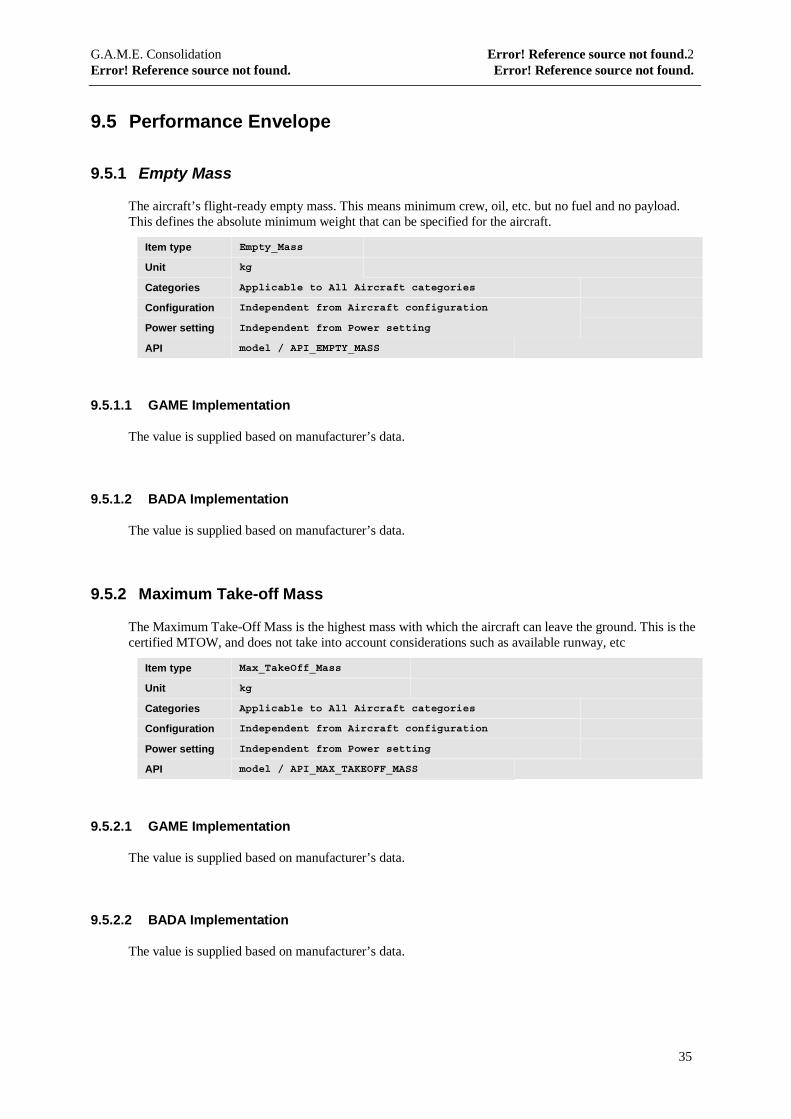
9.5.1 Empty Mass
The aircraft’s flight-ready empty mass. This means minimum crew, oil, etc. but no fuel and no payload.This defines the absolute minimum weight that can be specified for the aircraft.
Item type Empty_Mass
Unit kg
Categories Applicable to All Aircraft categories
Configuration Independent from Aircraft configuration
Power setting Independent from Power setting
API model / API_EMPTY_MASS
9.5.1.1 GAME Implementation
The value is supplied based on manufacturer’s data.
9.5.1.2 BADA Implementation
The value is supplied based on manufacturer’s data.
9.5.2 Maximum Take-off Mass
The Maximum Take-Off Mass is the highest mass with which the aircraft can leave the ground. This is thecertified MTOW, and does not take into account considerations such as available runway, etc
Item type Max_TakeOff_Mass
Unit kg
Categories Applicable to All Aircraft categories
Configuration Independent from Aircraft configuration
Power setting Independent from Power setting
API model / API_MAX_TAKEOFF_MASS
9.5.2.1 GAME Implementation
The value is supplied based on manufacturer’s data.
9.5.2.2 BADA Implementation
The value is supplied based on manufacturer’s data.

G.A.M.E. Consolidation Error! Reference source not found.2Error! Reference source not found. Error! Reference source not found.
36
9.5.3 Maximum Landing Mass
The Maximum Landing Mass is the highest mass allowed for a landing. This is the certified Landing mass,and does not take into account considerations such as available runway, etc
Item type Max_Landing_Mass
Unit kg
Categories Applicable to All Aircraft categories
Configuration Independent from Aircraft configuration
Power setting Independent from Power setting
API model / API_MAX_LANDING_MASS
9.5.3.1 GAME Implementation
The value is supplied based on manufacturer’s data.
9.5.3.2 BADA Implementation
BADA does not supply this data. Therefore a non-restrictive value is returned : the maximum takeoff mass.
9.5.4 Ceiling - Certified
The Certified Ceiling is the maximum altitude at which the Aircraft is allowed to fly during normaloperations. For the Clean Configuration this limit is usually based upon maximum pressure-differentialbetween the cabin and the outside atmosphere. For non-clean Configurations other considerations may set alower limit.
Item type Ceiling_Cert
Unit ft
Categories Applicable to All Aircraft categories
Configuration Specified for each Aircraft configuration
Power setting Independent from Power setting
API model / API_CEILING_CERTIFIED
9.5.4.1 GAME Implementation
The value is supplied based on manufacturer’s data.
9.5.4.2 BADA Implementation
The value is supplied based on manufacturer’s data.
G.A.M.E. Consolidation Error! Reference source not found.2Error! Reference source not found. Error! Reference source not found.
37
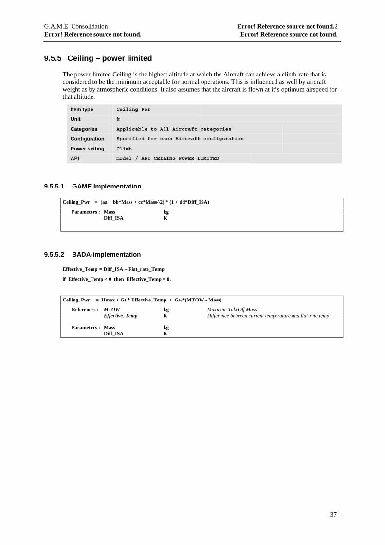
9.5.5 Ceiling – power limited
The power-limited Ceiling is the highest altitude at which the Aircraft can achieve a climb-rate that isconsidered to be the minimum acceptable for normal operations. This is influenced as well by aircraftweight as by atmospheric conditions. It also assumes that the aircraft is flown at it’s optimum airspeed forthat altitude.
Item type Ceiling_Pwr
Unit ft
Categories Applicable to All Aircraft categories
Configuration Specified for each Aircraft configuration
Power setting Climb
API model / API_CEILING_POWER_LIMITED
9.5.5.1 GAME Implementation
Ceiling_Pwr = (aa + bb*Mass + cc*Mass^2) * (1 + dd*Diff_ISA)
Parameters : Mass kgDiff_ISA K
9.5.5.2 BADA-implementation
Effective_Temp = Diff_ISA – Flat_rate_Temp
if Effective_Temp < 0 then Effective_Temp = 0.
Ceiling_Pwr = Hmax + Gt * Effective_Temp + Gw*(MTOW - Mass)
References : MTOW kg Maximim TakeOff MassEffective_Temp K Difference between current temperature and flat-rate temp..
Parameters : Mass kgDiff_ISA K

G.A.M.E. Consolidation Error! Reference source not found.2Error! Reference source not found. Error! Reference source not found.
38
9.5.6 Ceiling
The combined Ceiling takes into account the Certified ceiling, the Power-limited ceiling as well as checksthat there is a sufficient margin available above the buffeting speed to actually fly the speed at which theminimum climb-rate can be achieved.
Item type n/a
Unit ft
Categories Applicable to All Aircraft categories
Configuration Specified for each Aircraft configuration
Power setting Climb
API model / API_CEILING
9.5.6.1 Common Implementation
The minimum is calculated of the Certified ceiling and the Power-limited ceiling. Minimum speed(including margin) and maximum speed are calculated. If there is no room in between, the Ceiling islowered until an altitude is found where sufficient margin exists between minimum and maximum speed.
9.5.7 Maximum Cabin pressure differential
The maximum difference between the cabin-pressure and the pressure of the outside atmosphere. Thisdetermines in combination with the desired cabin descent-rates the maximum descent-rate during the firstphase of a high-level descent for most modern airplanes.
Item type Max_pressure_differential
Unit hPa
Categories Applicable to Jet, Turboprop, Jet with Afertburner, Jet CAS-only
Configuration Independent from Aircraft configuration
Power setting Independent from Power setting
API model / API_MAX_PRESSURE_DIFF
9.5.7.1 GAME Implementation
The value is supplied as specified by the aircraft manufacturer.
9.5.7.2 BADA Implementation
This data is not provided in the BADA-files. Therefore a value of 1013.2 mBar is returned. This specifiesan allowable difference of 1 full atmosphere and thus results in no limitations being imposed on cabinpressurisation.
G.A.M.E. Consolidation Error! Reference source not found.2Error! Reference source not found. Error! Reference source not found.
39
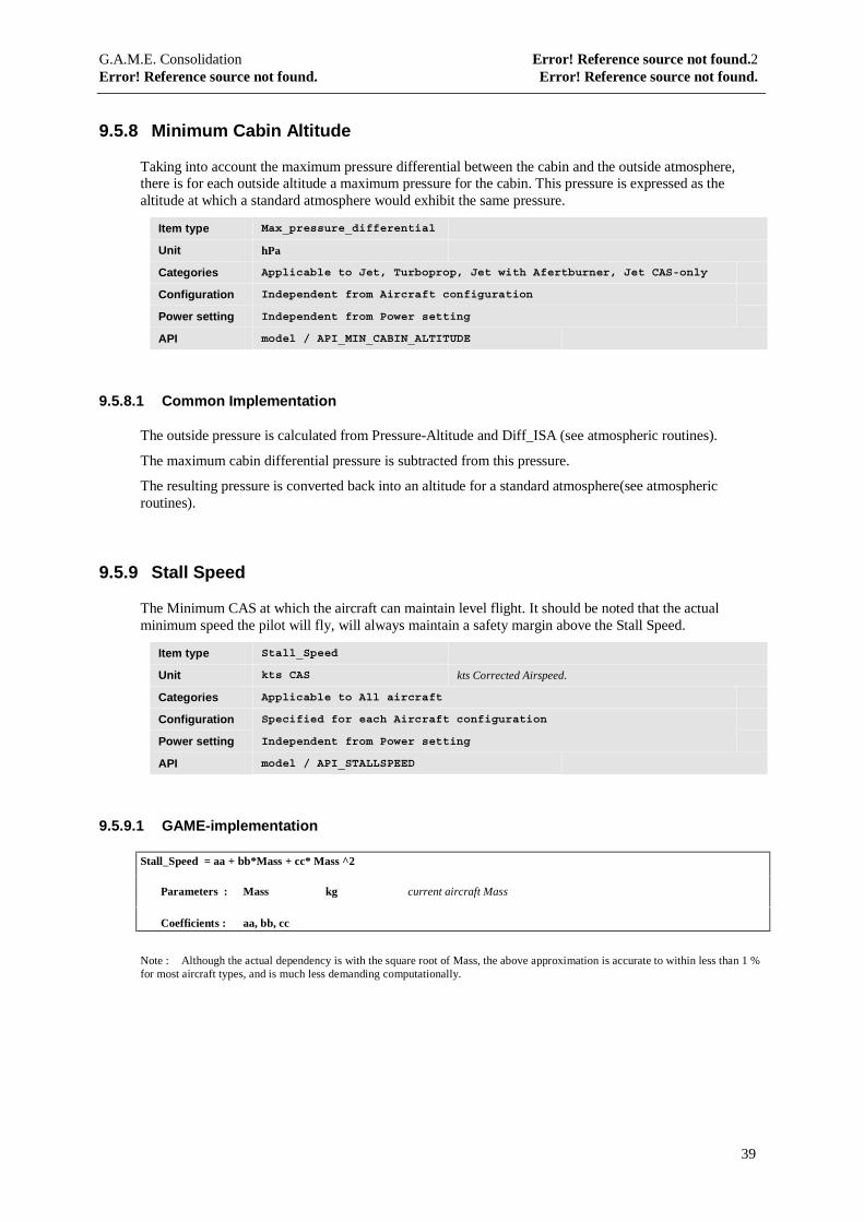
9.5.8 Minimum Cabin Altitude
Taking into account the maximum pressure differential between the cabin and the outside atmosphere,there is for each outside altitude a maximum pressure for the cabin. This pressure is expressed as thealtitude at which a standard atmosphere would exhibit the same pressure.
Item type Max_pressure_differential
Unit hPa
Categories Applicable to Jet, Turboprop, Jet with Afertburner, Jet CAS-only
Configuration Independent from Aircraft configuration
Power setting Independent from Power setting
API model / API_MIN_CABIN_ALTITUDE
9.5.8.1 Common Implementation
The outside pressure is calculated from Pressure-Altitude and Diff_ISA (see atmospheric routines).
The maximum cabin differential pressure is subtracted from this pressure.
The resulting pressure is converted back into an altitude for a standard atmosphere(see atmosphericroutines).
9.5.9 Stall Speed
The Minimum CAS at which the aircraft can maintain level flight. It should be noted that the actualminimum speed the pilot will fly, will always maintain a safety margin above the Stall Speed.
Item type Stall_Speed
Unit kts CAS kts Corrected Airspeed.
Categories Applicable to All aircraft
Configuration Specified for each Aircraft configuration
Power setting Independent from Power setting
API model / API_STALLSPEED
9.5.9.1 GAME-implementation
Stall_Speed = aa + bb*Mass + cc* Mass ^2
Parameters : Mass kg current aircraft Mass
Coefficients : aa, bb, cc
Note : Although the actual dependency is with the square root of Mass, the above approximation is accurate to within less than 1 %for most aircraft types, and is much less demanding computationally.
G.A.M.E. Consolidation Error! Reference source not found.2Error! Reference source not found. Error! Reference source not found.
40
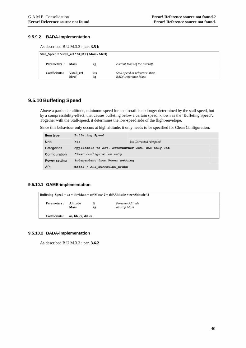
9.5.9.2 BADA-implementation
As described B.U.M.3.3 : par. 3.5 b
Stall_Speed = Vstall_ref * SQRT ( Mass / Mref)
Parameters : Mass kg current Mass of the aircraft
Coefficients : Vstall_ref kts Stall-speed at reference MassMref kg BADA reference Mass
9.5.10 Buffeting Speed
Above a particular altitude, minimum speed for an aircraft is no longer determined by the stall-speed, butby a compressibility-effect, that causes buffeting below a certain speed, known as the ‘Buffeting Speed’.Together with the Stall-speed, it determines the low-speed side of the flight-envelope.
Since this behaviour only occurs at high altitude, it only needs to be specified for Clean Configuration.
Item type Buffeting_Speed
Unit kts kts Corrected Airspeed.
Categories Applicable to Jet, Afterburner-Jet, CAS-only-Jet
Configuration Clean configuration only
Power setting Independent from Power setting
API model / API_BUFFETING_SPEED
9.5.10.1 GAME-implementation
Buffeting_Speed = aa + bb*Mass + cc*Mass^2 + dd*Altitude + ee*Altitude^2
Parameters : Altitude ft Pressure AltitudeMass kg aircraft Mass
Coefficients : aa, bb, cc, dd, ee
9.5.10.2 BADA-implementation
As described B.U.M.3.3 : par. 3.6.2

G.A.M.E. Consolidation Error! Reference source not found.2Error! Reference source not found. Error! Reference source not found.
41
9.5.11 Absolute minimum CAS
Returns the absolute minimum speed, expressed as CAS, at which the aircraft can be flown in levelstraight-line flight, not including a safety margin. It is the higher of the Stallspeed and the Buffeting speed(if appropriate for the aircraft type and configuration considered)
Item type n/a
Unit kts CAS kts Corrected Airspeed.
Categories Applicable to all Aircraft
Configuration Specified for each Aircraft configuration
Power setting Independent from Power setting
API model / API_CAS_MIN_ABS
9.5.11.1 Common implementation
The stallspeed is calculated as under 9.5.9.
If the aircraft is a Jet, Jet with Afterburner or a CAS-only-Jet in Clean configuration, the Buffeting speed iscalculated as under 9.5.10.
The higher of the above is returned as the result.
9.5.12 Absolute minimum Mach
Returns the absolute minimum speed, expressed as a Mach-number, at which the aircraft can be flownflown in level straight-line flight, not including a safety margin. It is the higher of the Stallspeed and theBuffeting speed (if appropriate for the aircraft type and configuration considered)
Item type n/a
Unit Mach number.
Categories Applicable to all Aircraft
Configuration Specified for each Aircraft configuration
Power setting Independent from Power setting
API model / API_MACH_MIN_ABS
9.5.12.1 Common implementation
The absolute minimum CAS is calculated as under 9.5.11.
The result is converted to a Mach-number by standard atmospheric routine.
G.A.M.E. Consolidation Error! Reference source not found.2Error! Reference source not found. Error! Reference source not found.
42
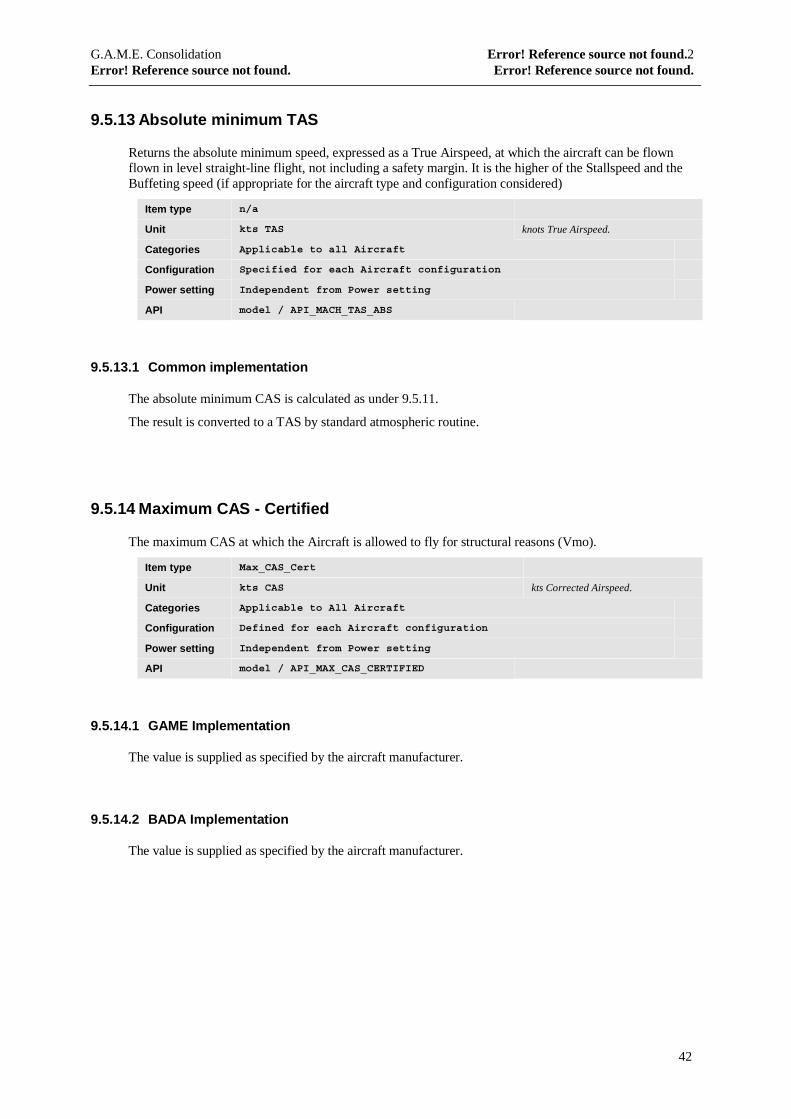
9.5.13 Absolute minimum TAS
Returns the absolute minimum speed, expressed as a True Airspeed, at which the aircraft can be flownflown in level straight-line flight, not including a safety margin. It is the higher of the Stallspeed and theBuffeting speed (if appropriate for the aircraft type and configuration considered)
Item type n/a
Unit kts TAS knots True Airspeed.
Categories Applicable to all Aircraft
Configuration Specified for each Aircraft configuration
Power setting Independent from Power setting
API model / API_MACH_TAS_ABS
9.5.13.1 Common implementation
The absolute minimum CAS is calculated as under 9.5.11.
The result is converted to a TAS by standard atmospheric routine.
9.5.14 Maximum CAS - Certified
The maximum CAS at which the Aircraft is allowed to fly for structural reasons (Vmo).
Item type Max_CAS_Cert
Unit kts CAS kts Corrected Airspeed.
Categories Applicable to All Aircraft
Configuration Defined for each Aircraft configuration
Power setting Independent from Power setting
API model / API_MAX_CAS_CERTIFIED
9.5.14.1 GAME Implementation
The value is supplied as specified by the aircraft manufacturer.
9.5.14.2 BADA Implementation
The value is supplied as specified by the aircraft manufacturer.
G.A.M.E. Consolidation Error! Reference source not found.2Error! Reference source not found. Error! Reference source not found.
43
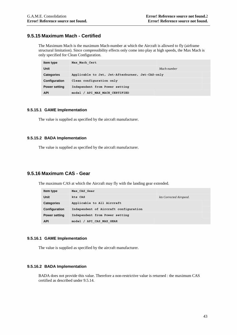
9.5.15 Maximum Mach - Certified
The Maximum Mach is the maximum Mach-number at which the Aircraft is allowed to fly (airframestructural limitation). Since compressibility effects only come into play at high speeds, the Max Mach isonly specified for Clean Configuration.
Item type Max_Mach_Cert
Unit Mach-number
Categories Applicable to Jet, Jet-Afterburner, Jet-CAS-only
Configuration Clean configuration only
Power setting Independent from Power setting
API model / API_MAX_MACH_CERTIFIED
9.5.15.1 GAME Implementation
The value is supplied as specified by the aircraft manufacturer.
9.5.15.2 BADA Implementation
The value is supplied as specified by the aircraft manufacturer.
9.5.16 Maximum CAS - Gear
The maximum CAS at which the Aircraft may fly with the landing gear extended.
Item type Max_CAS_Gear
Unit kts CAS kts Corrected Airspeed.
Categories Applicable to All Aircraft
Configuration Independent of Aircraft configuration
Power setting Independent from Power setting
API model / API_CAS_MAX_GEAR
9.5.16.1 GAME Implementation
The value is supplied as specified by the aircraft manufacturer.
9.5.16.2 BADA Implementation
BADA does not provide this value. Therefore a non-restrictive value is returned : the maximum CAScertified as described under 9.5.14.
G.A.M.E. Consolidation Error! Reference source not found.2Error! Reference source not found. Error! Reference source not found.
44
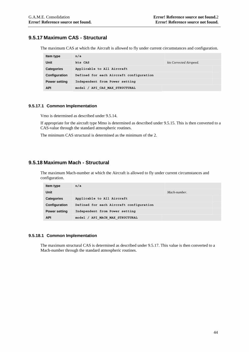
9.5.17 Maximum CAS - Structural
The maximum CAS at which the Aircraft is allowed to fly under current circumstances and configuration.
Item type n/a
Unit kts CAS kts Corrected Airspeed.
Categories Applicable to All Aircraft
Configuration Defined for each Aircraft configuration
Power setting Independent from Power setting
API model / API_CAS_MAX_STRUCTURAL
9.5.17.1 Common Implementation
Vmo is determined as described under 9.5.14.
If appropriate for the aircraft type Mmo is determined as described under 9.5.15. This is then converted to aCAS-value through the standard atmospheric routines.
The minimum CAS structural is determined as the minimum of the 2.
9.5.18 Maximum Mach - Structural
The maximum Mach-number at which the Aircraft is allowed to fly under current circumstances andconfiguration.
Item type n/a
Unit Mach-number.
Categories Applicable to All Aircraft
Configuration Defined for each Aircraft configuration
Power setting Independent from Power setting
API model / API_MACH_MAX_STRUCTURAL
9.5.18.1 Common Implementation
The maximum structural CAS is determined as described under 9.5.17. This value is then converted to aMach-number through the standard atmospheric routines.
G.A.M.E. Consolidation Error! Reference source not found.2Error! Reference source not found. Error! Reference source not found.
45
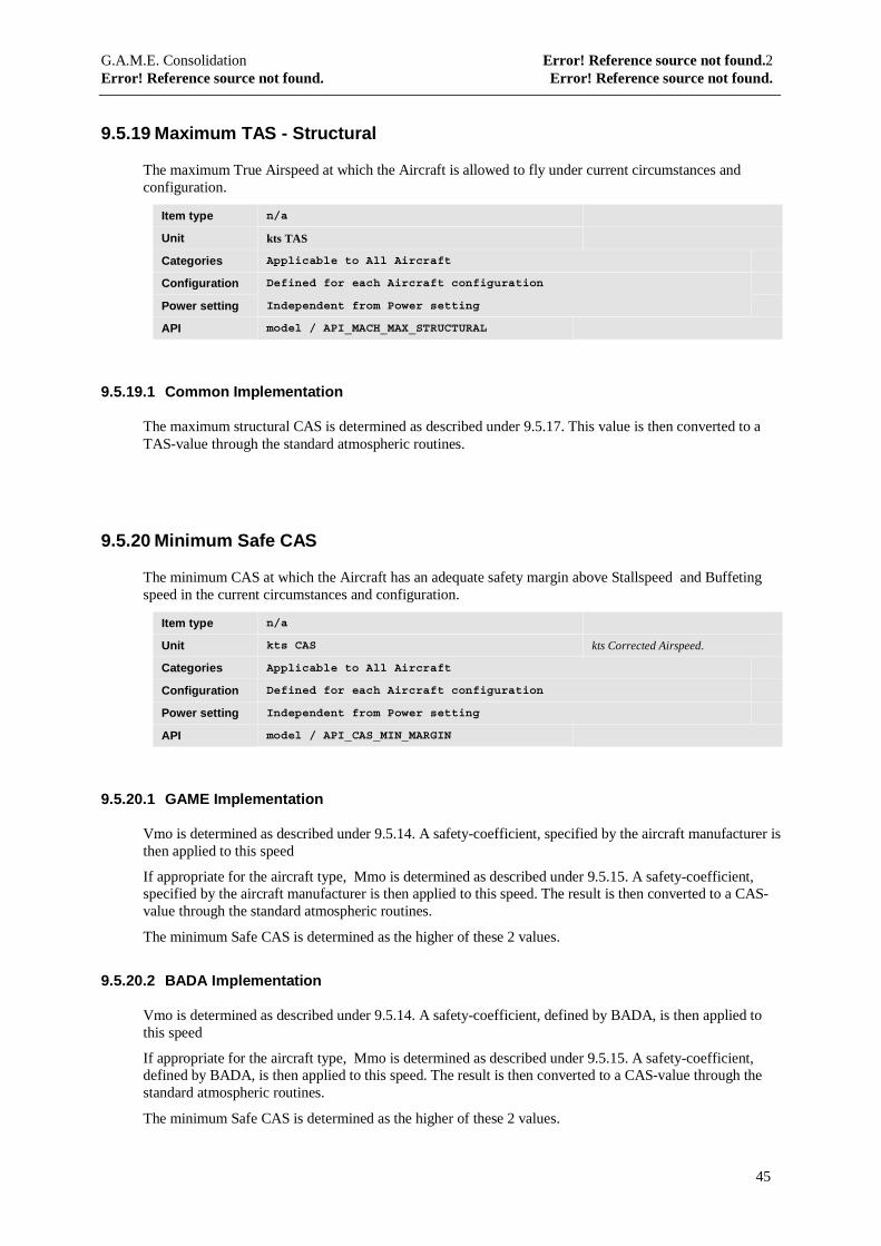
9.5.19 Maximum TAS - Structural
The maximum True Airspeed at which the Aircraft is allowed to fly under current circumstances andconfiguration.
Item type n/a
Unit kts TAS
Categories Applicable to All Aircraft
Configuration Defined for each Aircraft configuration
Power setting Independent from Power setting
API model / API_MACH_MAX_STRUCTURAL
9.5.19.1 Common Implementation
The maximum structural CAS is determined as described under 9.5.17. This value is then converted to aTAS-value through the standard atmospheric routines.
9.5.20 Minimum Safe CAS
The minimum CAS at which the Aircraft has an adequate safety margin above Stallspeed and Buffetingspeed in the current circumstances and configuration.
Item type n/a
Unit kts CAS kts Corrected Airspeed.
Categories Applicable to All Aircraft
Configuration Defined for each Aircraft configuration
Power setting Independent from Power setting
API model / API_CAS_MIN_MARGIN
9.5.20.1 GAME Implementation
Vmo is determined as described under 9.5.14. A safety-coefficient, specified by the aircraft manufacturer isthen applied to this speed
If appropriate for the aircraft type, Mmo is determined as described under 9.5.15. A safety-coefficient,specified by the aircraft manufacturer is then applied to this speed. The result is then converted to a CAS-value through the standard atmospheric routines.
The minimum Safe CAS is determined as the higher of these 2 values.
9.5.20.2 BADA Implementation
Vmo is determined as described under 9.5.14. A safety-coefficient, defined by BADA, is then applied tothis speed
If appropriate for the aircraft type, Mmo is determined as described under 9.5.15. A safety-coefficient,defined by BADA, is then applied to this speed. The result is then converted to a CAS-value through thestandard atmospheric routines.
The minimum Safe CAS is determined as the higher of these 2 values.
G.A.M.E. Consolidation Error! Reference source not found.2Error! Reference source not found. Error! Reference source not found.
46
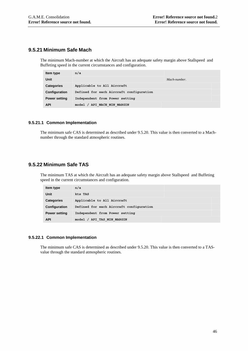
9.5.21 Minimum Safe Mach
The minimum Mach-number at which the Aircraft has an adequate safety margin above Stallspeed andBuffeting speed in the current circumstances and configuration.
Item type n/a
Unit Mach-number.
Categories Applicable to All Aircraft
Configuration Defined for each Aircraft configuration
Power setting Independent from Power setting
API model / API_MACH_MIN_MARGIN
9.5.21.1 Common Implementation
The minimum safe CAS is determined as described under 9.5.20. This value is then converted to a Mach-number through the standard atmospheric routines.
9.5.22 Minimum Safe TAS
The minimum TAS at which the Aircraft has an adequate safety margin above Stallspeed and Buffetingspeed in the current circumstances and configuration.
Item type n/a
Unit kts TAS
Categories Applicable to All Aircraft
Configuration Defined for each Aircraft configuration
Power setting Independent from Power setting
API model / API_TAS_MIN_MARGIN
9.5.22.1 Common Implementation
The minimum safe CAS is determined as described under 9.5.20. This value is then converted to a TAS-value through the standard atmospheric routines.
G.A.M.E. Consolidation Error! Reference source not found.2Error! Reference source not found. Error! Reference source not found.
47
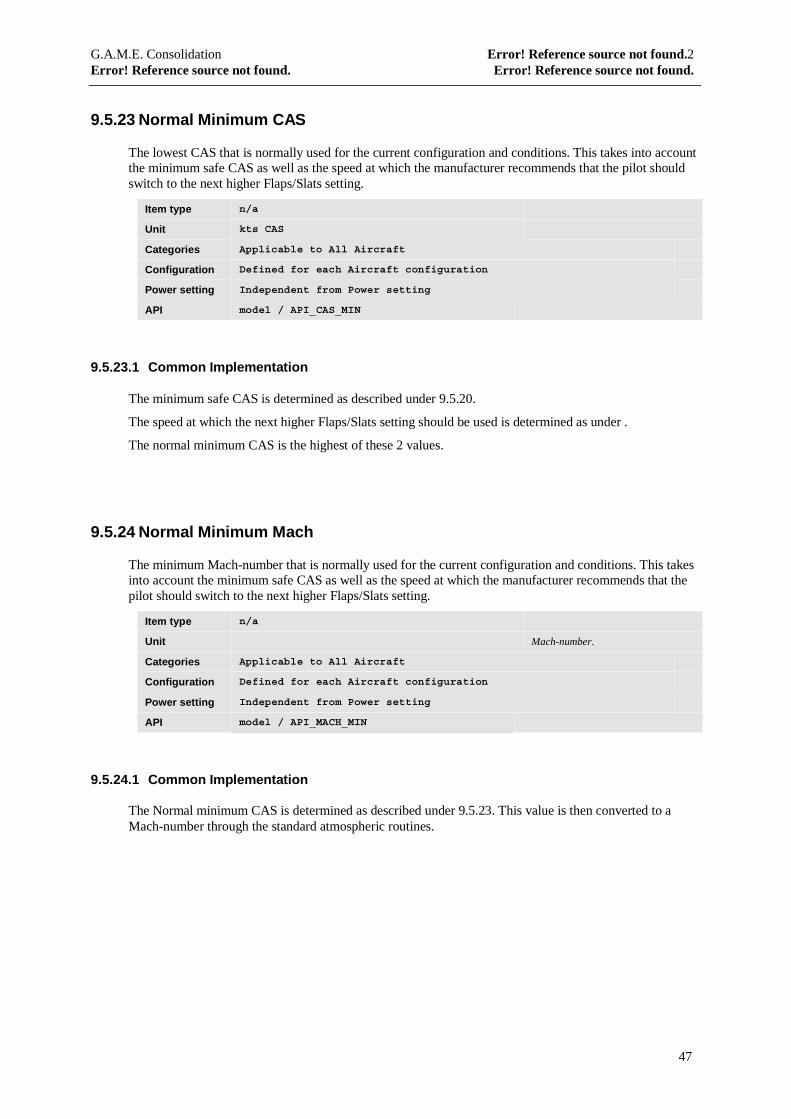
9.5.23 Normal Minimum CAS
The lowest CAS that is normally used for the current configuration and conditions. This takes into accountthe minimum safe CAS as well as the speed at which the manufacturer recommends that the pilot shouldswitch to the next higher Flaps/Slats setting.
Item type n/a
Unit kts CAS
Categories Applicable to All Aircraft
Configuration Defined for each Aircraft configuration
Power setting Independent from Power setting
API model / API_CAS_MIN
9.5.23.1 Common Implementation
The minimum safe CAS is determined as described under 9.5.20.
The speed at which the next higher Flaps/Slats setting should be used is determined as under .
The normal minimum CAS is the highest of these 2 values.
9.5.24 Normal Minimum Mach
The minimum Mach-number that is normally used for the current configuration and conditions. This takesinto account the minimum safe CAS as well as the speed at which the manufacturer recommends that thepilot should switch to the next higher Flaps/Slats setting.
Item type n/a
Unit Mach-number.
Categories Applicable to All Aircraft
Configuration Defined for each Aircraft configuration
Power setting Independent from Power setting
API model / API_MACH_MIN
9.5.24.1 Common Implementation
The Normal minimum CAS is determined as described under 9.5.23. This value is then converted to aMach-number through the standard atmospheric routines.
G.A.M.E. Consolidation Error! Reference source not found.2Error! Reference source not found. Error! Reference source not found.
48
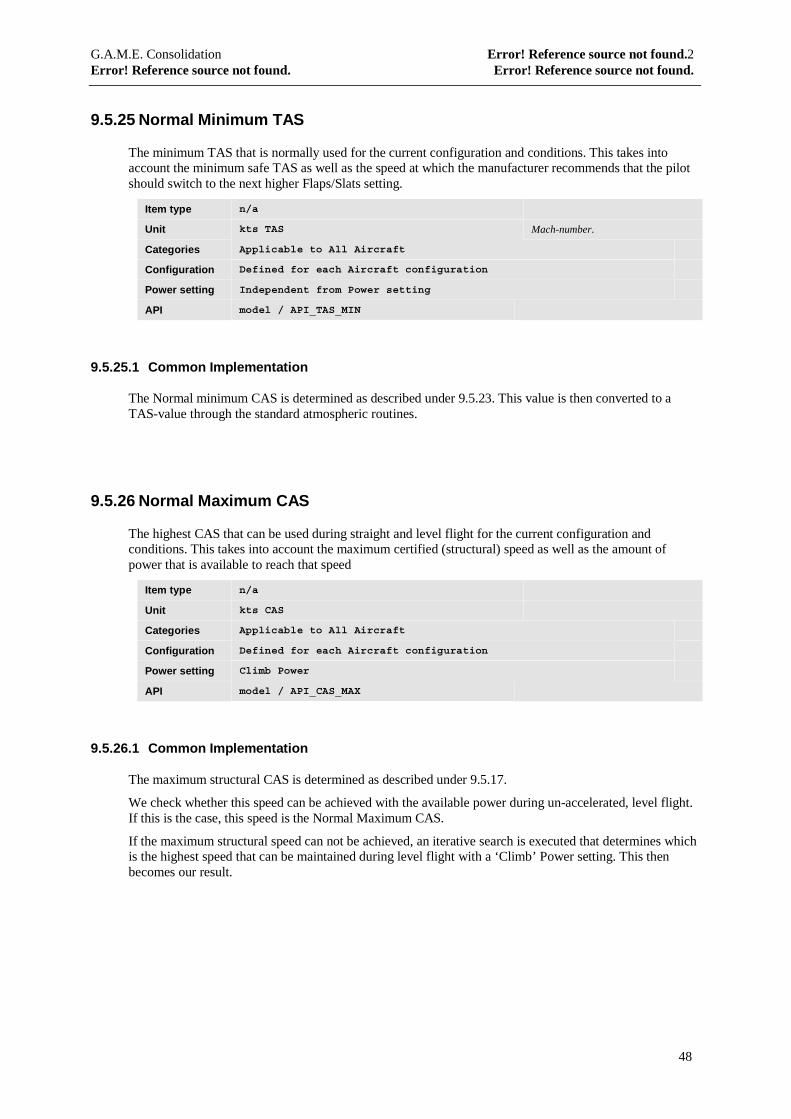
9.5.25 Normal Minimum TAS
The minimum TAS that is normally used for the current configuration and conditions. This takes intoaccount the minimum safe TAS as well as the speed at which the manufacturer recommends that the pilotshould switch to the next higher Flaps/Slats setting.
Item type n/a
Unit kts TAS Mach-number.
Categories Applicable to All Aircraft
Configuration Defined for each Aircraft configuration
Power setting Independent from Power setting
API model / API_TAS_MIN
9.5.25.1 Common Implementation
The Normal minimum CAS is determined as described under 9.5.23. This value is then converted to aTAS-value through the standard atmospheric routines.
9.5.26 Normal Maximum CAS
The highest CAS that can be used during straight and level flight for the current configuration andconditions. This takes into account the maximum certified (structural) speed as well as the amount ofpower that is available to reach that speed
Item type n/a
Unit kts CAS
Categories Applicable to All Aircraft
Configuration Defined for each Aircraft configuration
Power setting Climb Power
API model / API_CAS_MAX
9.5.26.1 Common Implementation
The maximum structural CAS is determined as described under 9.5.17.
We check whether this speed can be achieved with the available power during un-accelerated, level flight.If this is the case, this speed is the Normal Maximum CAS.
If the maximum structural speed can not be achieved, an iterative search is executed that determines whichis the highest speed that can be maintained during level flight with a ‘Climb’ Power setting. This thenbecomes our result.
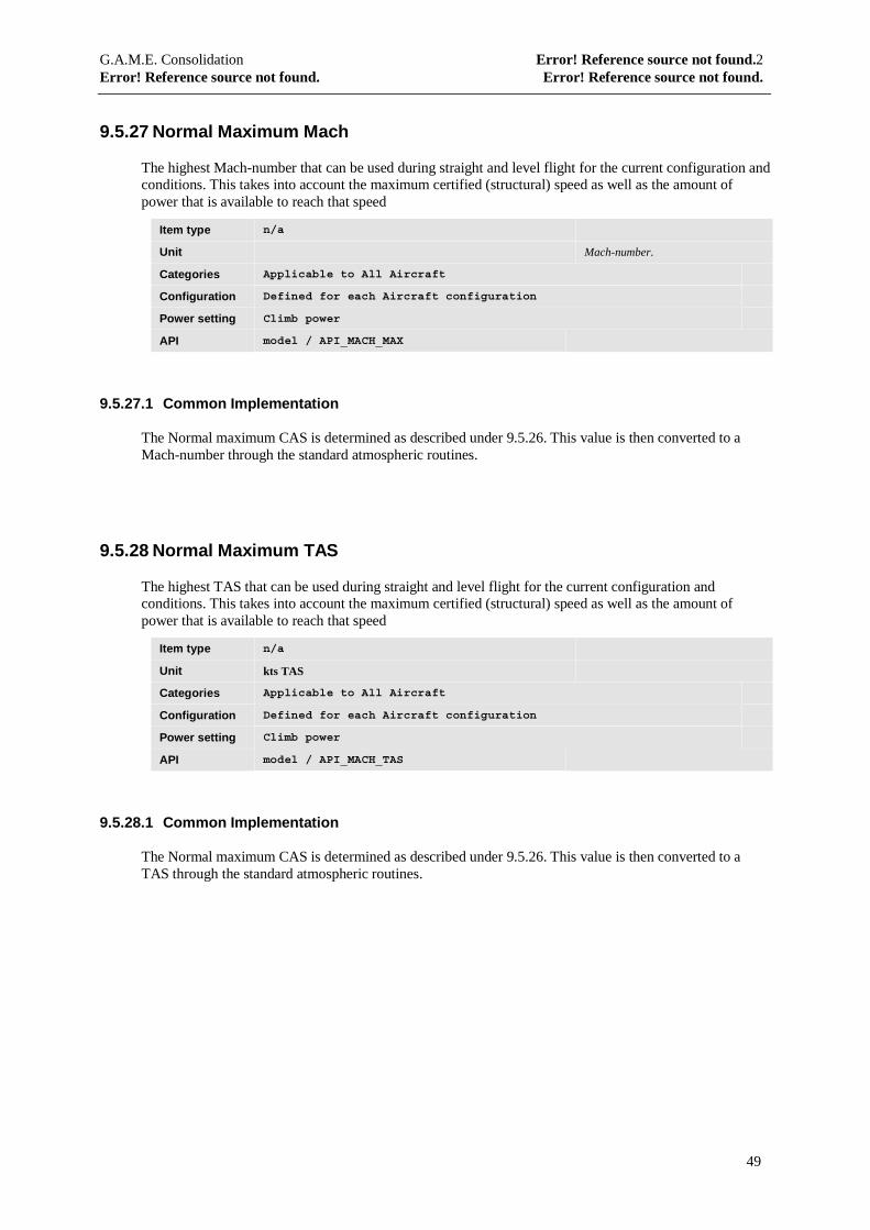
G.A.M.E. Consolidation Error! Reference source not found.2Error! Reference source not found. Error! Reference source not found.
49
9.5.27 Normal Maximum Mach
The highest Mach-number that can be used during straight and level flight for the current configuration andconditions. This takes into account the maximum certified (structural) speed as well as the amount ofpower that is available to reach that speed
Item type n/a
Unit Mach-number.
Categories Applicable to All Aircraft
Configuration Defined for each Aircraft configuration
Power setting Climb power
API model / API_MACH_MAX
9.5.27.1 Common Implementation
The Normal maximum CAS is determined as described under 9.5.26. This value is then converted to aMach-number through the standard atmospheric routines.
9.5.28 Normal Maximum TAS
The highest TAS that can be used during straight and level flight for the current configuration andconditions. This takes into account the maximum certified (structural) speed as well as the amount ofpower that is available to reach that speed
Item type n/a
Unit kts TAS
Categories Applicable to All Aircraft
Configuration Defined for each Aircraft configuration
Power setting Climb power
API model / API_MACH_TAS
9.5.28.1 Common Implementation
The Normal maximum CAS is determined as described under 9.5.26. This value is then converted to aTAS through the standard atmospheric routines.
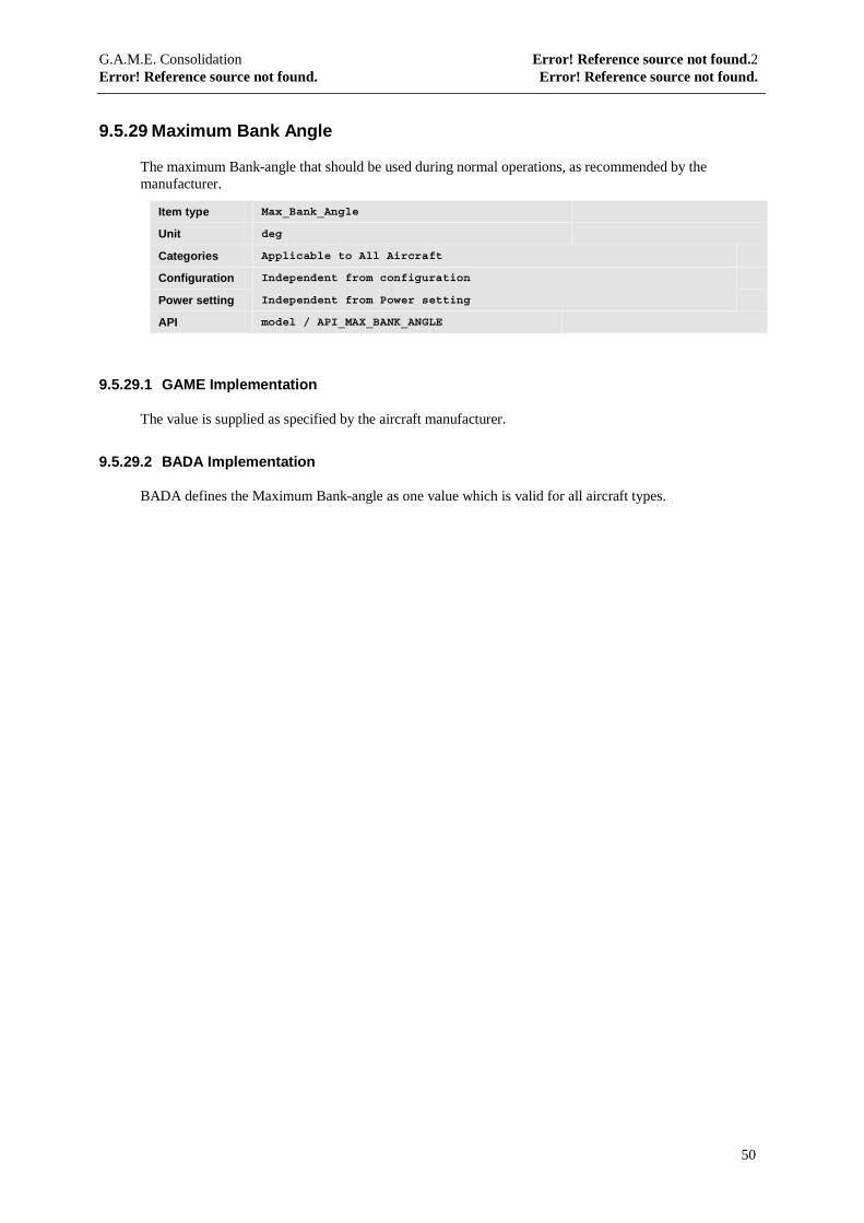
G.A.M.E. Consolidation Error! Reference source not found.2Error! Reference source not found. Error! Reference source not found.
50
9.5.29 Maximum Bank Angle
The maximum Bank-angle that should be used during normal operations, as recommended by themanufacturer.
Item type Max_Bank_Angle
Unit deg
Categories Applicable to All Aircraft
Configuration Independent from configuration
Power setting Independent from Power setting
API model / API_MAX_BANK_ANGLE
9.5.29.1 GAME Implementation
The value is supplied as specified by the aircraft manufacturer.
9.5.29.2 BADA Implementation
BADA defines the Maximum Bank-angle as one value which is valid for all aircraft types.

G.A.M.E. Consolidation Error! Reference source not found.2Error! Reference source not found. Error! Reference source not found.
51
9.6 Important speeds
9.6.1 CAS for Maximum Endurance
This is the CAS that yields the lowest fuel consumption per unit time.
Item type n/a
Unit kts CAS
Categories Applicable to All Aircraft categories
Configuration Defined for each Aircraft configuration
Power setting Cruise
API model / API_CAS_MAX_ENDURANCE
9.6.1.1 Common Implementation
The minimum safe CAS for current conditions is determined as described under 9.5.20.
The maximum structural CAS for current conditions is determined as described under 9.5.17.
An iterative search is made between these two speeds to determine the CAS that yields the lowest fuel-consumption.
9.6.2 Mach for Maximum Endurance
This is the Mach-number that yields the lowest fuel consumption per unit time.
Item type n/a
Unit
Categories Applicable to All Aircraft categories
Configuration Defined for each Aircraft configuration
Power setting Cruise
API model / API_MACH_MAX_ENDURANCE
9.6.2.1 Common Implementation
The CAS for maximum endurance is determined as described in 9.6.1. This value is then converted to aMach-number through the standard atmospheric routines.
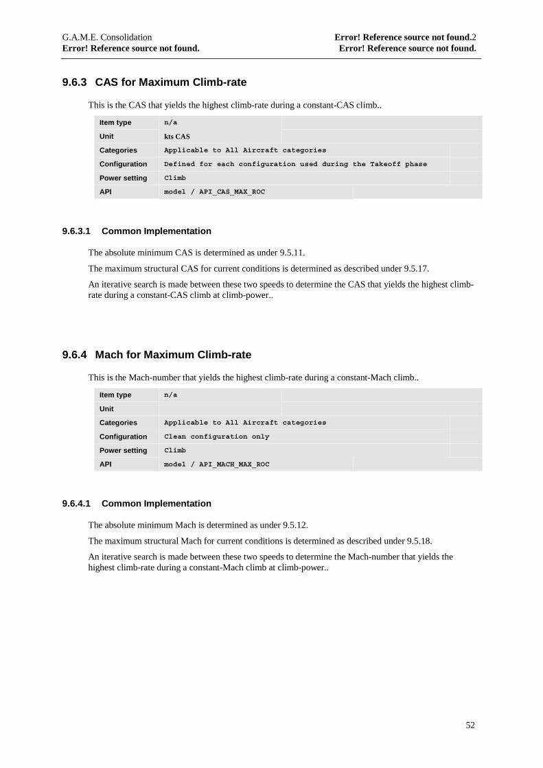
G.A.M.E. Consolidation Error! Reference source not found.2Error! Reference source not found. Error! Reference source not found.
52
9.6.3 CAS for Maximum Climb-rate
This is the CAS that yields the highest climb-rate during a constant-CAS climb..
Item type n/a
Unit kts CAS
Categories Applicable to All Aircraft categories
Configuration Defined for each configuration used during the Takeoff phase
Power setting Climb
API model / API_CAS_MAX_ROC
9.6.3.1 Common Implementation
The absolute minimum CAS is determined as under 9.5.11.
The maximum structural CAS for current conditions is determined as described under 9.5.17.
An iterative search is made between these two speeds to determine the CAS that yields the highest climb-rate during a constant-CAS climb at climb-power..
9.6.4 Mach for Maximum Climb-rate
This is the Mach-number that yields the highest climb-rate during a constant-Mach climb..
Item type n/a
Unit
Categories Applicable to All Aircraft categories
Configuration Clean configuration only
Power setting Climb
API model / API_MACH_MAX_ROC
9.6.4.1 Common Implementation
The absolute minimum Mach is determined as under 9.5.12.
The maximum structural Mach for current conditions is determined as described under 9.5.18.
An iterative search is made between these two speeds to determine the Mach-number that yields thehighest climb-rate during a constant-Mach climb at climb-power..
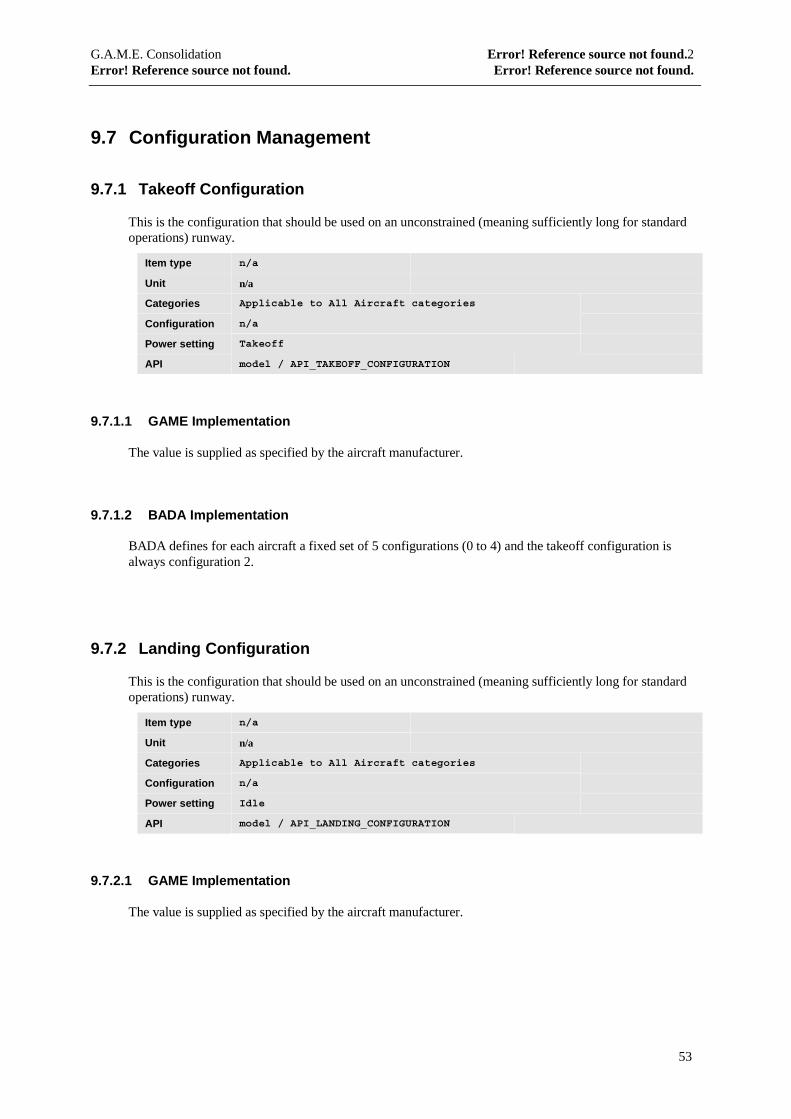
G.A.M.E. Consolidation Error! Reference source not found.2Error! Reference source not found. Error! Reference source not found.
53
9.7 Configuration Management
9.7.1 Takeoff Configuration
This is the configuration that should be used on an unconstrained (meaning sufficiently long for standardoperations) runway.
Item type n/a
Unit n/a
Categories Applicable to All Aircraft categories
Configuration n/a
Power setting Takeoff
API model / API_TAKEOFF_CONFIGURATION
9.7.1.1 GAME Implementation
The value is supplied as specified by the aircraft manufacturer.
9.7.1.2 BADA Implementation
BADA defines for each aircraft a fixed set of 5 configurations (0 to 4) and the takeoff configuration isalways configuration 2.
9.7.2 Landing Configuration
This is the configuration that should be used on an unconstrained (meaning sufficiently long for standardoperations) runway.
Item type n/a
Unit n/a
Categories Applicable to All Aircraft categories
Configuration n/a
Power setting Idle
API model / API_LANDING_CONFIGURATION
9.7.2.1 GAME Implementation
The value is supplied as specified by the aircraft manufacturer.
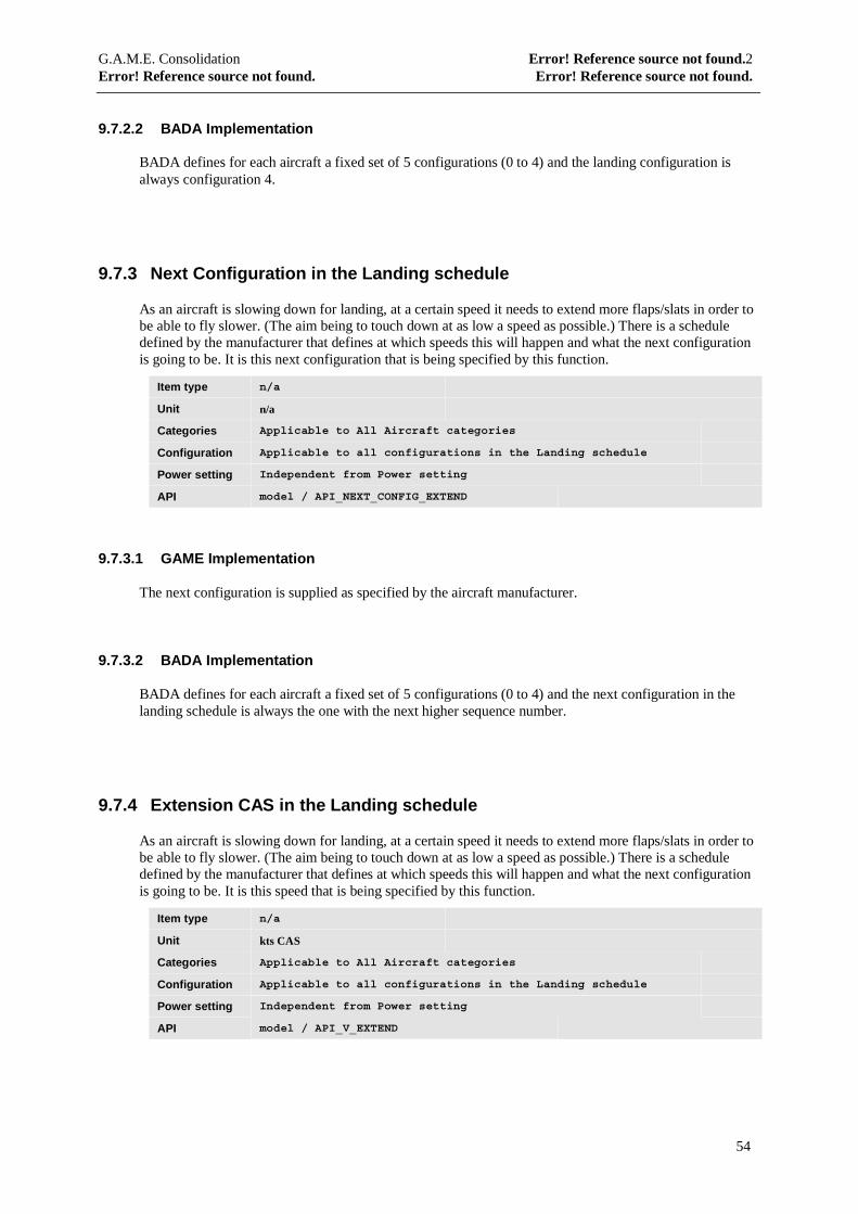
G.A.M.E. Consolidation Error! Reference source not found.2Error! Reference source not found. Error! Reference source not found.
54
9.7.2.2 BADA Implementation
BADA defines for each aircraft a fixed set of 5 configurations (0 to 4) and the landing configuration isalways configuration 4.
9.7.3 Next Configuration in the Landing schedule
As an aircraft is slowing down for landing, at a certain speed it needs to extend more flaps/slats in order tobe able to fly slower. (The aim being to touch down at as low a speed as possible.) There is a scheduledefined by the manufacturer that defines at which speeds this will happen and what the next configurationis going to be. It is this next configuration that is being specified by this function.
Item type n/a
Unit n/a
Categories Applicable to All Aircraft categories
Configuration Applicable to all configurations in the Landing schedule
Power setting Independent from Power setting
API model / API_NEXT_CONFIG_EXTEND
9.7.3.1 GAME Implementation
The next configuration is supplied as specified by the aircraft manufacturer.
9.7.3.2 BADA Implementation
BADA defines for each aircraft a fixed set of 5 configurations (0 to 4) and the next configuration in thelanding schedule is always the one with the next higher sequence number.
9.7.4 Extension CAS in the Landing schedule
As an aircraft is slowing down for landing, at a certain speed it needs to extend more flaps/slats in order tobe able to fly slower. (The aim being to touch down at as low a speed as possible.) There is a scheduledefined by the manufacturer that defines at which speeds this will happen and what the next configurationis going to be. It is this speed that is being specified by this function.
Item type n/a
Unit kts CAS
Categories Applicable to All Aircraft categories
Configuration Applicable to all configurations in the Landing schedule
Power setting Independent from Power setting
API model / API_V_EXTEND
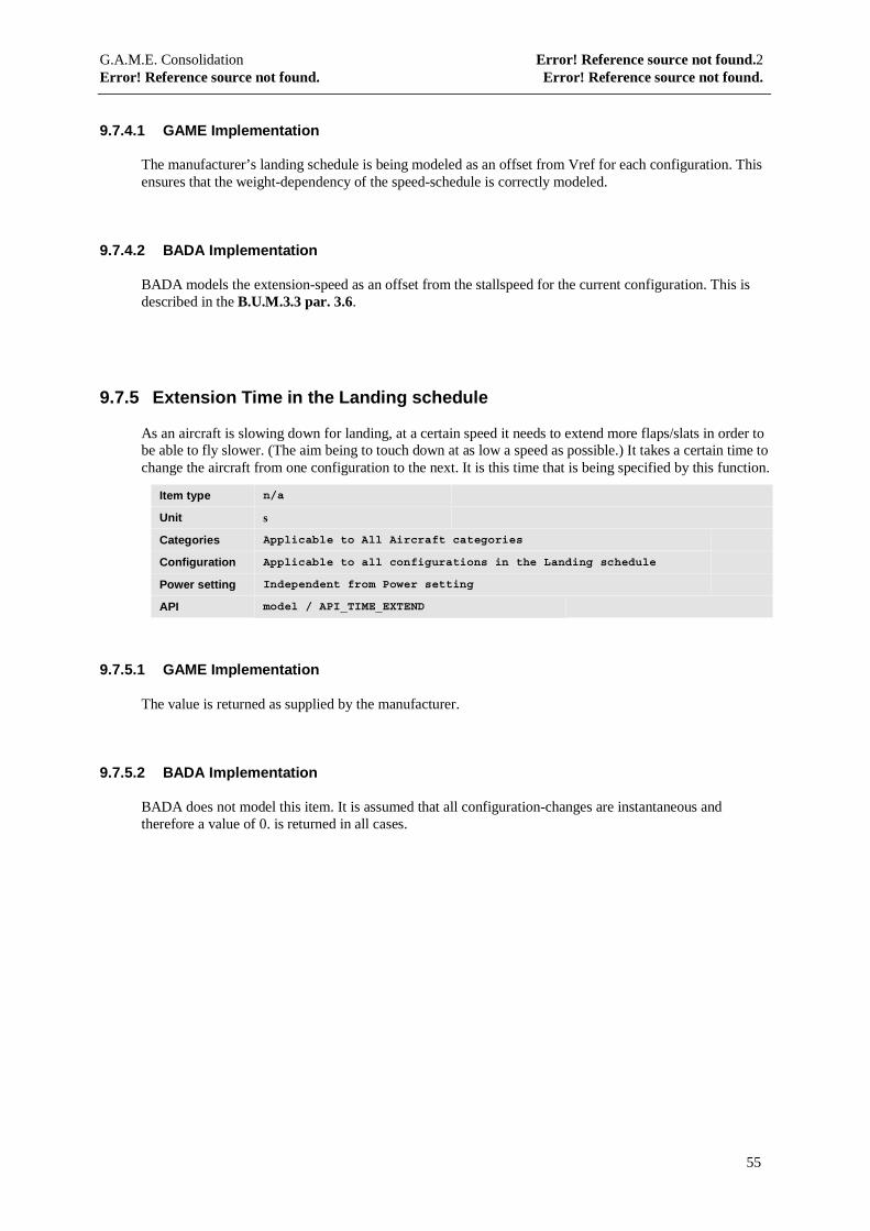
G.A.M.E. Consolidation Error! Reference source not found.2Error! Reference source not found. Error! Reference source not found.
55
9.7.4.1 GAME Implementation
The manufacturer’s landing schedule is being modeled as an offset from Vref for each configuration. Thisensures that the weight-dependency of the speed-schedule is correctly modeled.
9.7.4.2 BADA Implementation
BADA models the extension-speed as an offset from the stallspeed for the current configuration. This isdescribed in the B.U.M.3.3 par. 3.6.
9.7.5 Extension Time in the Landing schedule
As an aircraft is slowing down for landing, at a certain speed it needs to extend more flaps/slats in order tobe able to fly slower. (The aim being to touch down at as low a speed as possible.) It takes a certain time tochange the aircraft from one configuration to the next. It is this time that is being specified by this function.
Item type n/a
Unit s
Categories Applicable to All Aircraft categories
Configuration Applicable to all configurations in the Landing schedule
Power setting Independent from Power setting
API model / API_TIME_EXTEND
9.7.5.1 GAME Implementation
The value is returned as supplied by the manufacturer.
9.7.5.2 BADA Implementation
BADA does not model this item. It is assumed that all configuration-changes are instantaneous andtherefore a value of 0. is returned in all cases.

G.A.M.E. Consolidation Error! Reference source not found.2Error! Reference source not found. Error! Reference source not found.
56
9.7.6 Next Configuration in the Takeoff schedule
As an aircraft is accelerating after takeoff, at a certain speed it needs to retract flaps/slats in order to be ableto fly faster. There is a schedule defined by the manufacturer that defines at which speeds this will happenand what the next configuration is going to be. It is this next configuration that is being specified by thisfunction.
Item type n/a
Unit n/a
Categories Applicable to All Aircraft categories
Configuration Applicable to all configurations in the Takeoff schedule
Power setting Independent from Power setting
API model / API_NEXT_CONFIG_RETRACT
9.7.6.1 GAME Implementation
The next configuration is supplied as specified by the aircraft manufacturer.
9.7.6.2 BADA Implementation
BADA defines for each aircraft a fixed set of 5 configurations (0 to 4) and the next configuration in thetakeoff schedule is always the one with the next lower sequence number.
9.7.7 Retraction CAS in the Takeoff schedule
As an aircraft is accelerating after takeoff, at a certain speed it needs to retract flaps/slats in order to be ableto fly faster. There is a schedule defined by the manufacturer that defines at which speeds this will happenand what the next configuration is going to be. It is this speed that is being specified by this function.
Item type n/a
Unit kts CAS
Categories Applicable to All Aircraft categories
Configuration Applicable to all configurations in the Takeoff schedule
Power setting Independent from Power setting
API model / API_V_RETRACT
9.7.7.1 GAME Implementation
The manufacturer’s Takeoff schedule is being modeled as an offset from V2 for each configuration. Thisensures that the weight-dependency of the speed-schedule is correctly modeled.
9.7.7.2 BADA Implementation
BADA models the retraction-speed as an offset from the stallspeed for the current configuration. This isdescribed in the B.U.M.3.3 par. 3.6.
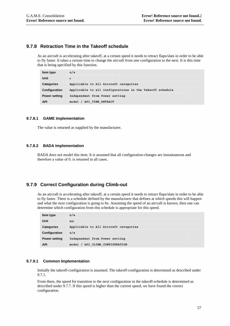
G.A.M.E. Consolidation Error! Reference source not found.2Error! Reference source not found. Error! Reference source not found.
57
9.7.8 Retraction Time in the Takeoff schedule
As an aircraft is accelerating after takeoff, at a certain speed it needs to retract flaps/slats in order to be ableto fly faster. It takes a certain time to change the aircraft from one configuration to the next. It is this timethat is being specified by this function.
Item type n/a
Unit s
Categories Applicable to All Aircraft categories
Configuration Applicable to all configurations in the Takeoff schedule
Power setting Independent from Power setting
API model / API_TIME_RETRACT
9.7.8.1 GAME Implementation
The value is returned as supplied by the manufacturer.
9.7.8.2 BADA Implementation
BADA does not model this item. It is assumed that all configuration-changes are instantaneous andtherefore a value of 0. is returned in all cases.
9.7.9 Correct Configuration during Climb-out
As an aircraft is accelerating after takeoff, at a certain speed it needs to retract flaps/slats in order to be ableto fly faster. There is a schedule defined by the manufacturer that defines at which speeds this will happenand what the next configuration is going to be. Assuming the speed of an aircraft is known, then one candetermine which configuration from this schedule is appropriate for this speed.
Item type n/a
Unit n/a
Categories Applicable to All Aircraft categories
Configuration n/a
Power setting Independent from Power setting
API model / API_CLIMB_CONFIGURATION
9.7.9.1 Common Implementation
Initially the takeoff-configuration is assumed. The takeoff-configuration is determined as described under9.7.1.
From there, the speed for transition to the next configuration in the takeoff-schedule is determined asdescribed under 9.7.7. If this speed is higher than the current speed, we have found the correctconfiguration.
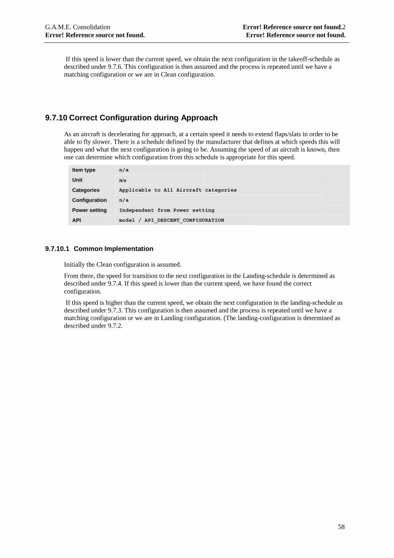
G.A.M.E. Consolidation Error! Reference source not found.2Error! Reference source not found. Error! Reference source not found.
58
If this speed is lower than the current speed, we obtain the next configuration in the takeoff-schedule asdescribed under 9.7.6. This configuration is then assumed and the process is repeated until we have amatching configuration or we are in Clean configuration.
9.7.10 Correct Configuration during Approach
As an aircraft is decelerating for approach, at a certain speed it needs to extend flaps/slats in order to beable to fly slower. There is a schedule defined by the manufacturer that defines at which speeds this willhappen and what the next configuration is going to be. Assuming the speed of an aircraft is known, thenone can determine which configuration from this schedule is appropriate for this speed.
Item type n/a
Unit n/a
Categories Applicable to All Aircraft categories
Configuration n/a
Power setting Independent from Power setting
API model / API_DESCENT_CONFIGURATION
9.7.10.1 Common Implementation
Initially the Clean configuration is assumed.
From there, the speed for transition to the next configuration in the Landing-schedule is determined asdescribed under 9.7.4. If this speed is lower than the current speed, we have found the correctconfiguration.
If this speed is higher than the current speed, we obtain the next configuration in the landing-schedule asdescribed under 9.7.3. This configuration is then assumed and the process is repeated until we have amatching configuration or we are in Landing configuration. (The landing-configuration is determined asdescribed under 9.7.2.
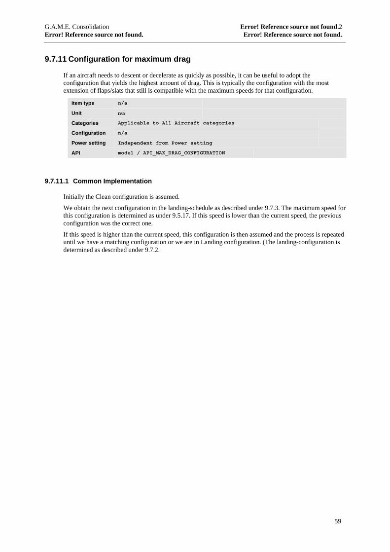
G.A.M.E. Consolidation Error! Reference source not found.2Error! Reference source not found. Error! Reference source not found.
59
9.7.11 Configuration for maximum drag
If an aircraft needs to descent or decelerate as quickly as possible, it can be useful to adopt theconfiguration that yields the highest amount of drag. This is typically the configuration with the mostextension of flaps/slats that still is compatible with the maximum speeds for that configuration.
Item type n/a
Unit n/a
Categories Applicable to All Aircraft categories
Configuration n/a
Power setting Independent from Power setting
API model / API_MAX_DRAG_CONFIGURATION
9.7.11.1 Common Implementation
Initially the Clean configuration is assumed.
We obtain the next configuration in the landing-schedule as described under 9.7.3. The maximum speed forthis configuration is determined as under 9.5.17. If this speed is lower than the current speed, the previousconfiguration was the correct one.
If this speed is higher than the current speed, this configuration is then assumed and the process is repeateduntil we have a matching configuration or we are in Landing configuration. (The landing-configuration isdetermined as described under 9.7.2.
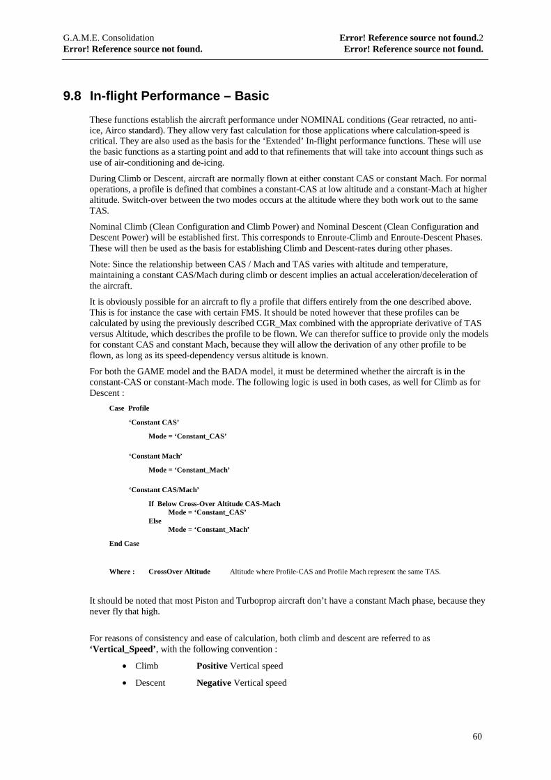
G.A.M.E. Consolidation Error! Reference source not found.2Error! Reference source not found. Error! Reference source not found.
60
9.8 In-flight Performance – Basic
These functions establish the aircraft performance under NOMINAL conditions (Gear retracted, no anti-ice, Airco standard). They allow very fast calculation for those applications where calculation-speed iscritical. They are also used as the basis for the ‘Extended’ In-flight performance functions. These will usethe basic functions as a starting point and add to that refinements that will take into account things such asuse of air-conditioning and de-icing.
During Climb or Descent, aircraft are normally flown at either constant CAS or constant Mach. For normaloperations, a profile is defined that combines a constant-CAS at low altitude and a constant-Mach at higheraltitude. Switch-over between the two modes occurs at the altitude where they both work out to the sameTAS.
Nominal Climb (Clean Configuration and Climb Power) and Nominal Descent (Clean Configuration andDescent Power) will be established first. This corresponds to Enroute-Climb and Enroute-Descent Phases.These will then be used as the basis for establishing Climb and Descent-rates during other phases.
Note: Since the relationship between CAS / Mach and TAS varies with altitude and temperature,maintaining a constant CAS/Mach during climb or descent implies an actual acceleration/deceleration ofthe aircraft.
It is obviously possible for an aircraft to fly a profile that differs entirely from the one described above.This is for instance the case with certain FMS. It should be noted however that these profiles can becalculated by using the previously described CGR_Max combined with the appropriate derivative of TASversus Altitude, which describes the profile to be flown. We can therefor suffice to provide only the modelsfor constant CAS and constant Mach, because they will allow the derivation of any other profile to beflown, as long as its speed-dependency versus altitude is known.
For both the GAME model and the BADA model, it must be determined whether the aircraft is in theconstant-CAS or constant-Mach mode. The following logic is used in both cases, as well for Climb as forDescent :
Case Profile
‘Constant CAS’
Mode = ‘Constant_CAS’
‘Constant Mach’
Mode = ‘Constant_Mach’
‘Constant CAS/Mach’
If Below Cross-Over Altitude CAS-MachMode = ‘Constant_CAS’
ElseMode = ‘Constant_Mach’
End Case
Where : CrossOver Altitude Altitude where Profile-CAS and Profile Mach represent the same TAS.
It should be noted that most Piston and Turboprop aircraft don’t have a constant Mach phase, because theynever fly that high.
For reasons of consistency and ease of calculation, both climb and descent are referred to as‘Vertical_Speed’, with the following convention :
• Climb Positive Vertical speed
• Descent Negative Vertical speed
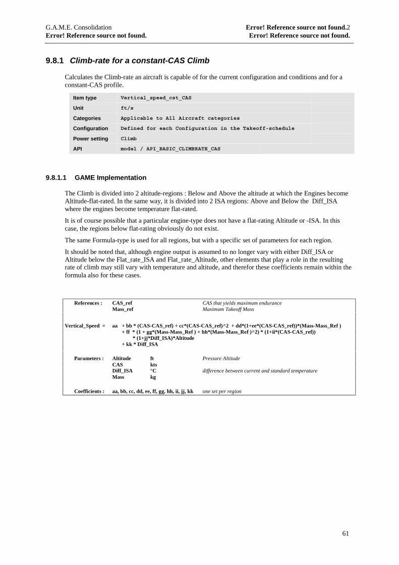
G.A.M.E. Consolidation Error! Reference source not found.2Error! Reference source not found. Error! Reference source not found.
61
9.8.1 Climb-rate for a constant-CAS Climb
Calculates the Climb-rate an aircraft is capable of for the current configuration and conditions and for aconstant-CAS profile.
Item type Vertical_speed_cst_CAS
Unit ft/s
Categories Applicable to All Aircraft categories
Configuration Defined for each Configuration in the Takeoff-schedule
Power setting Climb
API model / API_BASIC_CLIMBRATE_CAS
9.8.1.1 GAME Implementation
The Climb is divided into 2 altitude-regions : Below and Above the altitude at which the Engines becomeAltitude-flat-rated. In the same way, it is divided into 2 ISA regions: Above and Below the Diff_ISAwhere the engines become temperature flat-rated.
It is of course possible that a particular engine-type does not have a flat-rating Altitude or -ISA. In thiscase, the regions below flat-rating obviously do not exist.
The same Formula-type is used for all regions, but with a specific set of parameters for each region.
It should be noted that, although engine output is assumed to no longer vary with either Diff_ISA orAltitude below the Flat_rate_ISA and Flat_rate_Altitude, other elements that play a role in the resultingrate of climb may still vary with temperature and altitude, and therefor these coefficients remain within theformula also for these cases.
References : CAS_ref CAS that yields maximum enduranceMass_ref Maximum Takeoff Mass
Vertical_Speed = aa + bb * (CAS-CAS_ref) + cc*(CAS-CAS_ref)^2 + dd*(1+ee*(CAS-CAS_ref))*(Mass-Mass_Ref )+ ff * (1 + gg*(Mass-Mass_Ref ) + hh*(Mass-Mass_Ref )^2) * (1+ii*(CAS-CAS_ref))
* (1+jj*Diff_ISA)*Altitude+ kk * Diff_ISA
Parameters : Altitude ft Pressure AltitudeCAS ktsDiff_ISA °C difference between current and standard temperatureMass kg
Coefficients : aa, bb, cc, dd, ee, ff, gg, hh, ii, jj, kk one set per region
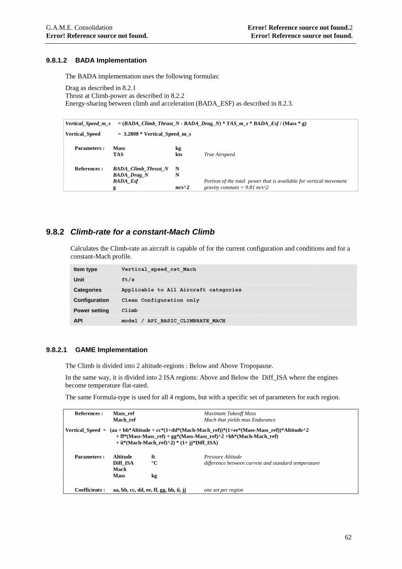
G.A.M.E. Consolidation Error! Reference source not found.2Error! Reference source not found. Error! Reference source not found.
62
9.8.1.2 BADA Implementation
The BADA implementation uses the following formulas:
Drag as described in 8.2.1Thrust at Climb-power as described in 8.2.2Energy-sharing between climb and acceleration (BADA_ESF) as described in 8.2.3.
Vertical_Speed_m_s = (BADA_Climb_Thrust_N - BADA_Drag_N) * TAS_m_s * BADA_Esf / (Mass * g)
Vertical_Speed = 3.2808 * Vertical_Speed_m_s
Parameters : Mass kgTAS kts True Airspeed.
References : BADA_Climb_Thrust_N NBADA_Drag_N NBADA_Esf Portion of the total power that is available for vertical movementg m/s^2 gravity constant = 9.81 m/s^2
9.8.2 Climb-rate for a constant-Mach Climb
Calculates the Climb-rate an aircraft is capable of for the current configuration and conditions and for aconstant-Mach profile.
Item type Vertical_speed_cst_Mach
Unit ft/s
Categories Applicable to All Aircraft categories
Configuration Clean Configuration only
Power setting Climb
API model / API_BASIC_CLIMBRATE_MACH
9.8.2.1 GAME Implementation
The Climb is divided into 2 altitude-regions : Below and Above Tropopause.
In the same way, it is divided into 2 ISA regions: Above and Below the Diff_ISA where the enginesbecome temperature flat-rated.
The same Formula-type is used for all 4 regions, but with a specific set of parameters for each region.
References : Mass_ref Maximum Takeoff MassMach_ref Mach that yields max Endurance
Vertical_Speed = (aa + bb*Altitude + cc*(1+dd*(Mach-Mach_ref))*(1+ee*(Mass-Mass_ref))*Altitude^2+ ff*(Mass-Mass_ref) + gg*(Mass-Mass_ref)^2 +hh*(Mach-Mach_ref)+ ii*(Mach-Mach_ref)^2) * (1+ jj*Diff_ISA)
Parameters : Altitude ft Pressure AltitudeDiff_ISA °C difference between current and standard temperatureMachMass kg
Coefficients : aa, bb, cc, dd, ee, ff, gg, hh, ii, jj one set per region

G.A.M.E. Consolidation Error! Reference source not found.2Error! Reference source not found. Error! Reference source not found.
63
9.8.2.2 BADA Implementation
The BADA implementation uses the following formulas:
Drag as described in 8.2.1Thrust at Climb-power as described in 8.2.2Energy-sharing between climb and acceleration (BADA_ESF) as described in 8.2.3.
Vertical_Speed_m_s = (BADA_Climb_Thrust_N - BADA_Drag_N) * TAS_m_s * BADA_Esf / (Mass * g)
Vertical_Speed = 3.2808 * Vertical_Speed_m_s
Parameters : Mass kgTAS kts True Airspeed.
References : BADA_Climb_Thrust_N NBADA_Drag_N NBADA_Esf Portion of the total power that is available for vertical movementg m/s^2 gravity constant = 9.81 m/s^2
The BADA-implementation is the same as for a constant-CAS climb, except for the fact that the Energy-share function is different (see 8.2.3).
9.8.3 Descent-rate for a constant-CAS Descent
Calculates the Descent-rate an aircraft is capable of at idle power for the current configuration andconditions and for a constant-CAS profile.
It should be noted that for jet aircraft this is the normal descent procedure. Propeller-driven aircraft (bothPiston and TurboProp) are usually descended at a constant descent rate. In these cases the idle descent rateis used to establish a reference.
Item type Vertical_speed_cst_CAS
Unit ft/s
Categories Applicable to All Aircraft categories
Configuration Defined for each Configuration in the Landing-schedule
Power setting Idle
API model / API_BASIC_DESCENTRATE_CAS
9.8.3.1 GAME Implementation
The following formula is used
Vertical_Speed = (aa + bb*Altitude + cc*CAS + dd*CAS^2 + (ee*CAS+ff*CAS^2)*Mass) * (1 + gg*Diff_ISA)
Parameters : Altitude ft Pressure AltitudeCAS ktsDiff_ISA °CMass kg
Coefficients : aa, bb, cc, dd, ee, ff, gg
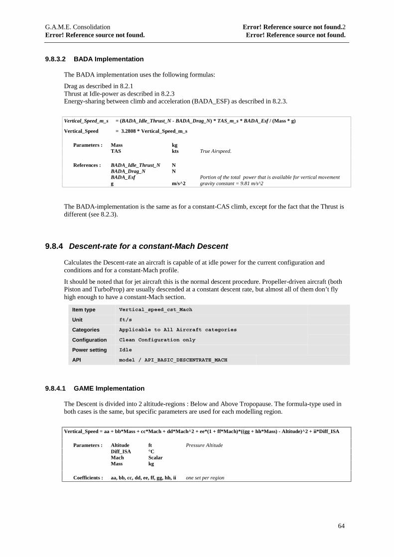
G.A.M.E. Consolidation Error! Reference source not found.2Error! Reference source not found. Error! Reference source not found.
64
9.8.3.2 BADA Implementation
The BADA implementation uses the following formulas:
Drag as described in 8.2.1Thrust at Idle-power as described in 8.2.3Energy-sharing between climb and acceleration (BADA_ESF) as described in 8.2.3.
Vertical_Speed_m_s = (BADA_Idle_Thrust_N - BADA_Drag_N) * TAS_m_s * BADA_Esf / (Mass * g)
Vertical_Speed = 3.2808 * Vertical_Speed_m_s
Parameters : Mass kgTAS kts True Airspeed.
References : BADA_Idle_Thrust_N NBADA_Drag_N NBADA_Esf Portion of the total power that is available for vertical movementg m/s^2 gravity constant = 9.81 m/s^2
The BADA-implementation is the same as for a constant-CAS climb, except for the fact that the Thrust isdifferent (see 8.2.3).
9.8.4 Descent-rate for a constant-Mach Descent
Calculates the Descent-rate an aircraft is capable of at idle power for the current configuration andconditions and for a constant-Mach profile.
It should be noted that for jet aircraft this is the normal descent procedure. Propeller-driven aircraft (bothPiston and TurboProp) are usually descended at a constant descent rate, but almost all of them don’t flyhigh enough to have a constant-Mach section.
Item type Vertical_speed_cst_Mach
Unit ft/s
Categories Applicable to All Aircraft categories
Configuration Clean Configuration only
Power setting Idle
API model / API_BASIC_DESCENTRATE_MACH
9.8.4.1 GAME Implementation
The Descent is divided into 2 altitude-regions : Below and Above Tropopause. The formula-type used inboth cases is the same, but specific parameters are used for each modelling region.
Vertical_Speed = aa + bb*Mass + cc*Mach + dd*Mach^2 + ee*(1 + ff*Mach)*((gg + hh*Mass) - Altitude)^2 + ii*Diff_ISA
Parameters : Altitude ft Pressure AltitudeDiff_ISA °CMach ScalarMass kg
Coefficients : aa, bb, cc, dd, ee, ff, gg, hh, ii one set per region
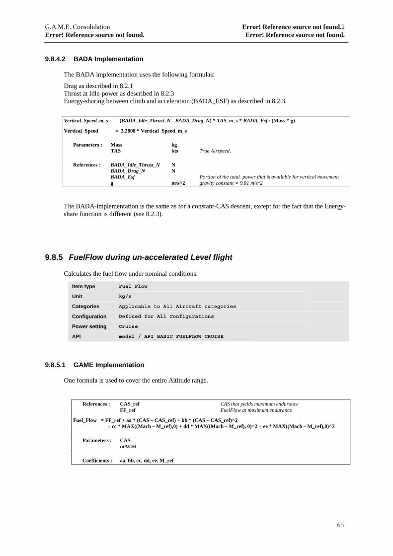
G.A.M.E. Consolidation Error! Reference source not found.2Error! Reference source not found. Error! Reference source not found.
65
9.8.4.2 BADA Implementation
The BADA implementation uses the following formulas:
Drag as described in 8.2.1Thrust at Idle-power as described in 8.2.3Energy-sharing between climb and acceleration (BADA_ESF) as described in 8.2.3.
Vertical_Speed_m_s = (BADA_Idle_Thrust_N - BADA_Drag_N) * TAS_m_s * BADA_Esf / (Mass * g)
Vertical_Speed = 3.2808 * Vertical_Speed_m_s
Parameters : Mass kgTAS kts True Airspeed.
References : BADA_Idle_Thrust_N NBADA_Drag_N NBADA_Esf Portion of the total power that is available for vertical movementg m/s^2 gravity constant = 9.81 m/s^2
The BADA-implementation is the same as for a constant-CAS descent, except for the fact that the Energy-share function is different (see 8.2.3).
9.8.5 FuelFlow during un-accelerated Level flight
Calculates the fuel flow under nominal conditions.
Item type Fuel_Flow
Unit kg/s
Categories Applicable to All Aircraft categories
Configuration Defined for All Configurations
Power setting Cruise
API model / API_BASIC_FUELFLOW_CRUISE
9.8.5.1 GAME Implementation
One formula is used to cover the entire Altitude range.
References : CAS_ref CAS that yields maximum enduranceFF_ref FuelFlow at maximum endurance
Fuel_Flow = FF_ref + aa * (CAS – CAS_ref) + bb * (CAS – CAS_ref)^2+ cc * MAX((Mach – M_ref),0) + dd * MAX((Mach – M_ref), 0)^2 + ee * MAX((Mach – M_ref),0)^3
Parameters : CASmACH
Coefficients : aa, bb, cc, dd, ee, M_ref
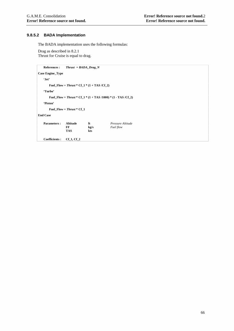
G.A.M.E. Consolidation Error! Reference source not found.2Error! Reference source not found. Error! Reference source not found.
66
9.8.5.2 BADA Implementation
The BADA implementation uses the following formulas:
Drag as described in 8.2.1Thrust for Cruise is equal to drag.
References : Thrust = BADA_Drag_N
Case Engine_Type
‘Jet’
Fuel_Flow = Thrust * Cf_1 * (1 + TAS /Cf_2)
‘Turbo’
Fuel_Flow = Thrust * Cf_1 * (1 + TAS /1000) * (1 - TAS /Cf_2)
‘Piston’
Fuel_Flow = Thrust * Cf_1
End Case
Parameters : Altitude ft Pressure AltitudeFF kg/s Fuel flowTAS kts
Coefficients : Cf_1, Cf_2

G.A.M.E. Consolidation Error! Reference source not found.2Error! Reference source not found. Error! Reference source not found.
67
9.9 In-flight Performance – Detailed
These functions allow the calculation of in-flight performance to a much higher level as the ones from theprevious paragraph, as they will include the effects of non-nominal conditions : use of airbrakes, anti-ice,gear, etc…
9.9.1 Climb-rate for a constant-CAS Climb
Calculates the Climb-rate an aircraft is capable of for the current configuration and conditions and for aconstant-CAS profile.
Item type Vertical_speed_cst_CAS
Unit ft/s
Categories Applicable to All Aircraft categories
Configuration Defined for each Configuration in the Takeoff-schedule
Power setting Climb / TakeOff / Afterburner
API model / API_CLIMBRATE_CAS
9.9.1.1 GAME Implementation
The Basic Climbrate is calculated as under 9.8.1.
Corrections are made for :
• Anti-ice• non-standard Airco• Power-setting• Transition of Configuration• Bank-angle
For each of the above a correction-factor is specified per aircraft type.
The correction-factors are applied in the following way:
References : Vertical_speed_ref Vertical speed obtained under nominal conditions
Vertical_speed = aa * Vertical_speed_ref
Coefficients : aa
9.9.1.2 BADA Implementation
The Basic Climbrate is calculated as under 9.8.1.
Corrections are made for :
• Power-setting• Bank-angle
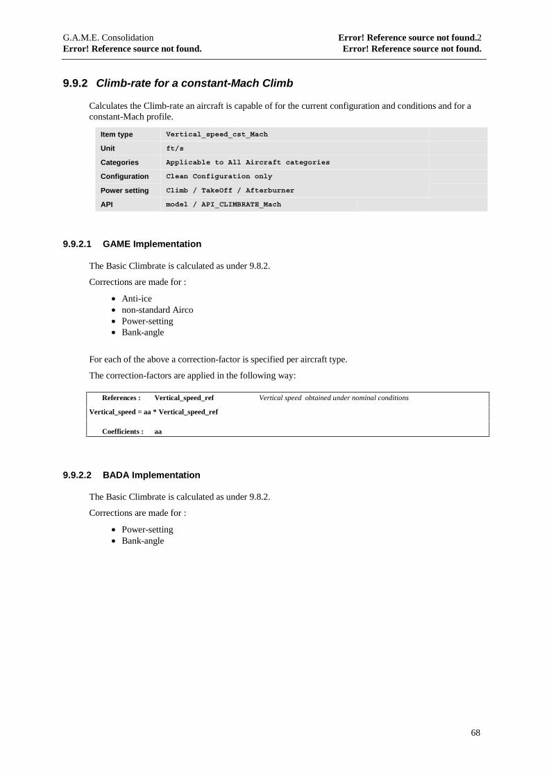
G.A.M.E. Consolidation Error! Reference source not found.2Error! Reference source not found. Error! Reference source not found.
68
9.9.2 Climb-rate for a constant-Mach Climb
Calculates the Climb-rate an aircraft is capable of for the current configuration and conditions and for aconstant-Mach profile.
Item type Vertical_speed_cst_Mach
Unit ft/s
Categories Applicable to All Aircraft categories
Configuration Clean Configuration only
Power setting Climb / TakeOff / Afterburner
API model / API_CLIMBRATE_Mach
9.9.2.1 GAME Implementation
The Basic Climbrate is calculated as under 9.8.2.
Corrections are made for :
• Anti-ice• non-standard Airco• Power-setting• Bank-angle
For each of the above a correction-factor is specified per aircraft type.
The correction-factors are applied in the following way:
References : Vertical_speed_ref Vertical speed obtained under nominal conditions
Vertical_speed = aa * Vertical_speed_ref
Coefficients : aa
9.9.2.2 BADA Implementation
The Basic Climbrate is calculated as under 9.8.2.
Corrections are made for :
• Power-setting• Bank-angle
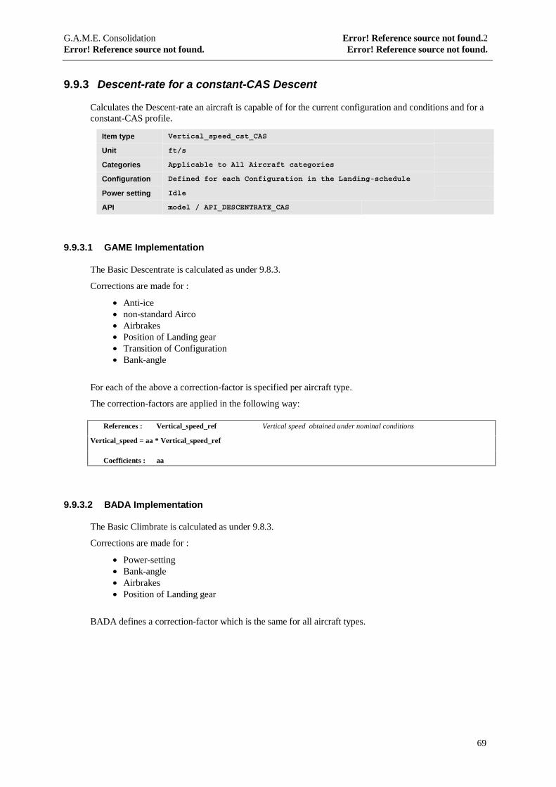
G.A.M.E. Consolidation Error! Reference source not found.2Error! Reference source not found. Error! Reference source not found.
69
9.9.3 Descent-rate for a constant-CAS Descent
Calculates the Descent-rate an aircraft is capable of for the current configuration and conditions and for aconstant-CAS profile.
Item type Vertical_speed_cst_CAS
Unit ft/s
Categories Applicable to All Aircraft categories
Configuration Defined for each Configuration in the Landing-schedule
Power setting Idle
API model / API_DESCENTRATE_CAS
9.9.3.1 GAME Implementation
The Basic Descentrate is calculated as under 9.8.3.
Corrections are made for :
• Anti-ice• non-standard Airco• Airbrakes• Position of Landing gear• Transition of Configuration• Bank-angle
For each of the above a correction-factor is specified per aircraft type.
The correction-factors are applied in the following way:
References : Vertical_speed_ref Vertical speed obtained under nominal conditions
Vertical_speed = aa * Vertical_speed_ref
Coefficients : aa
9.9.3.2 BADA Implementation
The Basic Climbrate is calculated as under 9.8.3.
Corrections are made for :
• Power-setting• Bank-angle• Airbrakes• Position of Landing gear
BADA defines a correction-factor which is the same for all aircraft types.
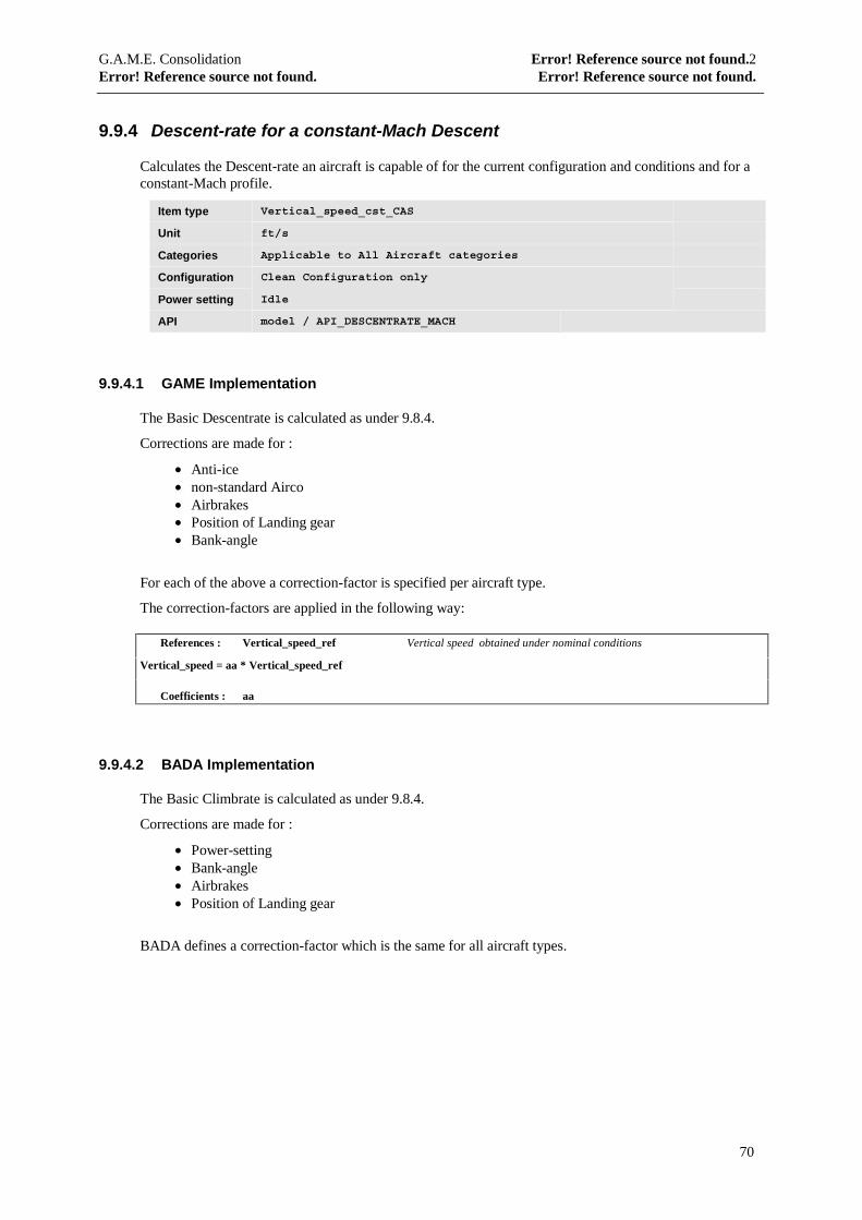
G.A.M.E. Consolidation Error! Reference source not found.2Error! Reference source not found. Error! Reference source not found.
70
9.9.4 Descent-rate for a constant-Mach Descent
Calculates the Descent-rate an aircraft is capable of for the current configuration and conditions and for aconstant-Mach profile.
Item type Vertical_speed_cst_CAS
Unit ft/s
Categories Applicable to All Aircraft categories
Configuration Clean Configuration only
Power setting Idle
API model / API_DESCENTRATE_MACH
9.9.4.1 GAME Implementation
The Basic Descentrate is calculated as under 9.8.4.
Corrections are made for :
• Anti-ice• non-standard Airco• Airbrakes• Position of Landing gear• Bank-angle
For each of the above a correction-factor is specified per aircraft type.
The correction-factors are applied in the following way:
References : Vertical_speed_ref Vertical speed obtained under nominal conditions
Vertical_speed = aa * Vertical_speed_ref
Coefficients : aa
9.9.4.2 BADA Implementation
The Basic Climbrate is calculated as under 9.8.4.
Corrections are made for :
• Power-setting• Bank-angle• Airbrakes• Position of Landing gear
BADA defines a correction-factor which is the same for all aircraft types.
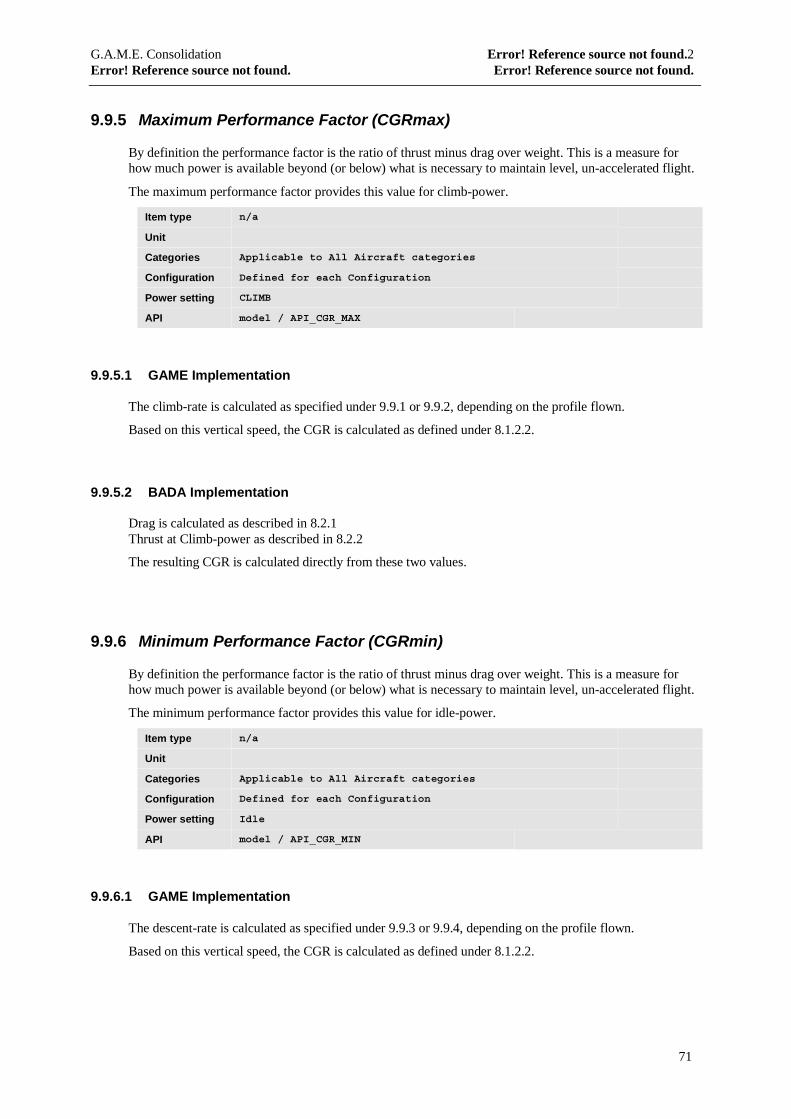
G.A.M.E. Consolidation Error! Reference source not found.2Error! Reference source not found. Error! Reference source not found.
71
9.9.5 Maximum Performance Factor (CGRmax)
By definition the performance factor is the ratio of thrust minus drag over weight. This is a measure forhow much power is available beyond (or below) what is necessary to maintain level, un-accelerated flight.
The maximum performance factor provides this value for climb-power.
Item type n/a
Unit
Categories Applicable to All Aircraft categories
Configuration Defined for each Configuration
Power setting CLIMB
API model / API_CGR_MAX
9.9.5.1 GAME Implementation
The climb-rate is calculated as specified under 9.9.1 or 9.9.2, depending on the profile flown.
Based on this vertical speed, the CGR is calculated as defined under 8.1.2.2.
9.9.5.2 BADA Implementation
Drag is calculated as described in 8.2.1Thrust at Climb-power as described in 8.2.2
The resulting CGR is calculated directly from these two values.
9.9.6 Minimum Performance Factor (CGRmin)
By definition the performance factor is the ratio of thrust minus drag over weight. This is a measure forhow much power is available beyond (or below) what is necessary to maintain level, un-accelerated flight.
The minimum performance factor provides this value for idle-power.
Item type n/a
Unit
Categories Applicable to All Aircraft categories
Configuration Defined for each Configuration
Power setting Idle
API model / API_CGR_MIN
9.9.6.1 GAME Implementation
The descent-rate is calculated as specified under 9.9.3 or 9.9.4, depending on the profile flown.
Based on this vertical speed, the CGR is calculated as defined under 8.1.2.2.
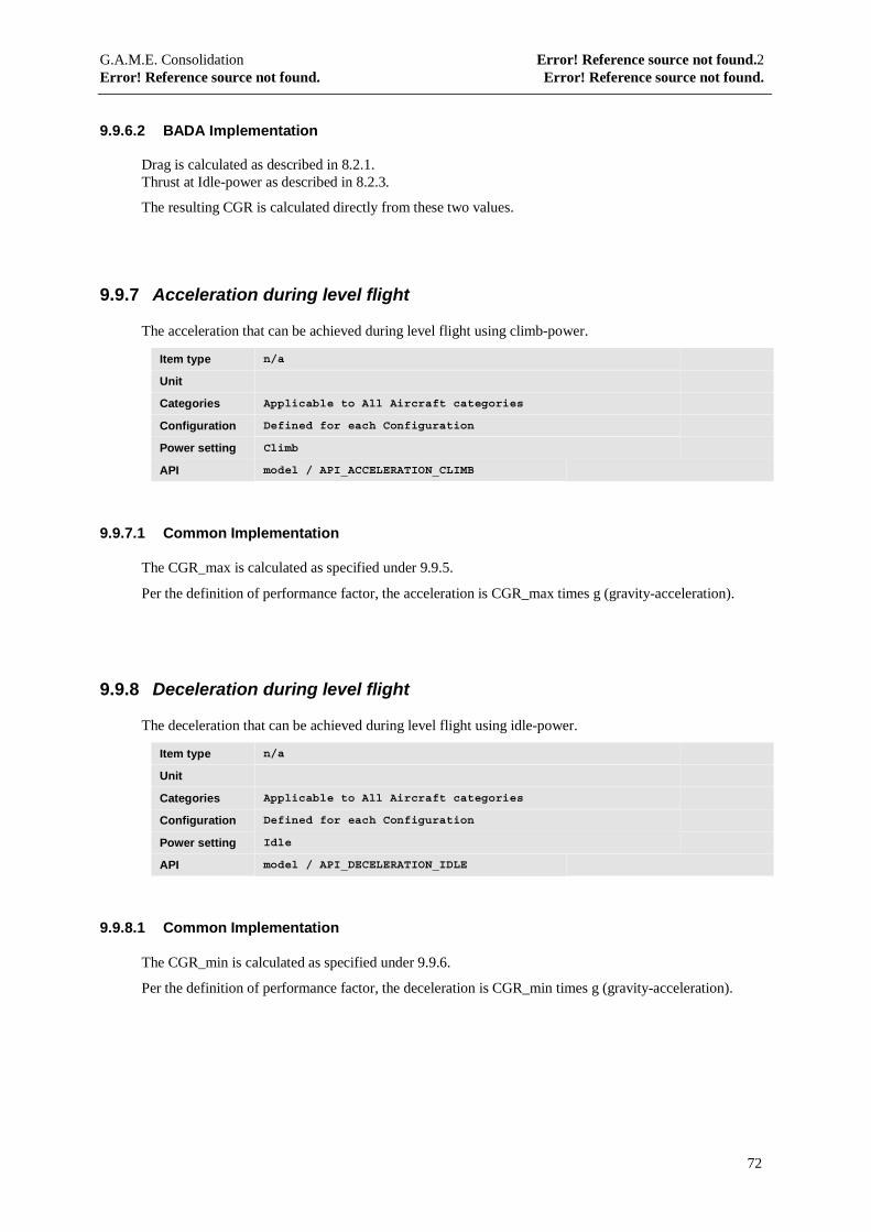
G.A.M.E. Consolidation Error! Reference source not found.2Error! Reference source not found. Error! Reference source not found.
72
9.9.6.2 BADA Implementation
Drag is calculated as described in 8.2.1.Thrust at Idle-power as described in 8.2.3.
The resulting CGR is calculated directly from these two values.
9.9.7 Acceleration during level flight
The acceleration that can be achieved during level flight using climb-power.
Item type n/a
Unit
Categories Applicable to All Aircraft categories
Configuration Defined for each Configuration
Power setting Climb
API model / API_ACCELERATION_CLIMB
9.9.7.1 Common Implementation
The CGR_max is calculated as specified under 9.9.5.
Per the definition of performance factor, the acceleration is CGR_max times g (gravity-acceleration).
9.9.8 Deceleration during level flight
The deceleration that can be achieved during level flight using idle-power.
Item type n/a
Unit
Categories Applicable to All Aircraft categories
Configuration Defined for each Configuration
Power setting Idle
API model / API_DECELERATION_IDLE
9.9.8.1 Common Implementation
The CGR_min is calculated as specified under 9.9.6.
Per the definition of performance factor, the deceleration is CGR_min times g (gravity-acceleration).
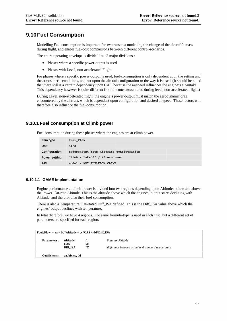
G.A.M.E. Consolidation Error! Reference source not found.2Error! Reference source not found. Error! Reference source not found.
73
9.10 Fuel Consumption
Modelling Fuel consumption is important for two reasons: modelling the change of the aircraft’s massduring flight, and enable fuel-cost comparisons between different control-scenarios.
The entire operating envelope is divided into 2 major divisions :
• Phases where a specific power-output is used
• Phases with Level, non-accelerated Flight
For phases where a specific power-output is used, fuel-consumption is only dependent upon the setting andthe atmospheric conditions, and not upon the aircraft configuration or the way it is used. (It should be notedthat there still is a certain dependency upon CAS, because the airspeed influences the engine’s air-intake.This dependency however is quite different from the one encountered during level, non-accelerated flight.)
During Level, non-accelerated flight, the engine’s power-output must match the aerodynamic dragencountered by the aircraft, which is dependent upon configuration and desired airspeed. These factors willtherefore also influence the fuel-consumption.
9.10.1 Fuel consumption at Climb power
Fuel consumption during these phases where the engines are at climb power.
Item type Fuel_Flow
Unit kg/s
Configuration Independent from Aircraft configuration
Power setting Climb / TakeOff / Afterburner
API model / API_FUELFLOW_CLIMB
9.10.1.1 GAME Implementation
Engine performance at climb-power is divided into two regions depending upon Altitude: below and abovethe Power Flat-rate Altitude. This is the altitude above which the engines’ output starts declining withAltitude, and therefor also their fuel-consumption.
There is also a Temperature Flat-Rated Diff_ISA defined. This is the Diff_ISA value above which theengines’ output declines with temperature.
In total therefore, we have 4 regions. The same formula-type is used in each case, but a different set ofparameters are specified for each region.
Fuel_Flow = aa + bb*Altitude + cc*CAS + dd*Diff_ISA
Parameters : Altitude ft Pressure AltitudeCAS ktsDiff_ISA °C difference between actual and standard temperature
Coefficients : aa, bb, cc, dd
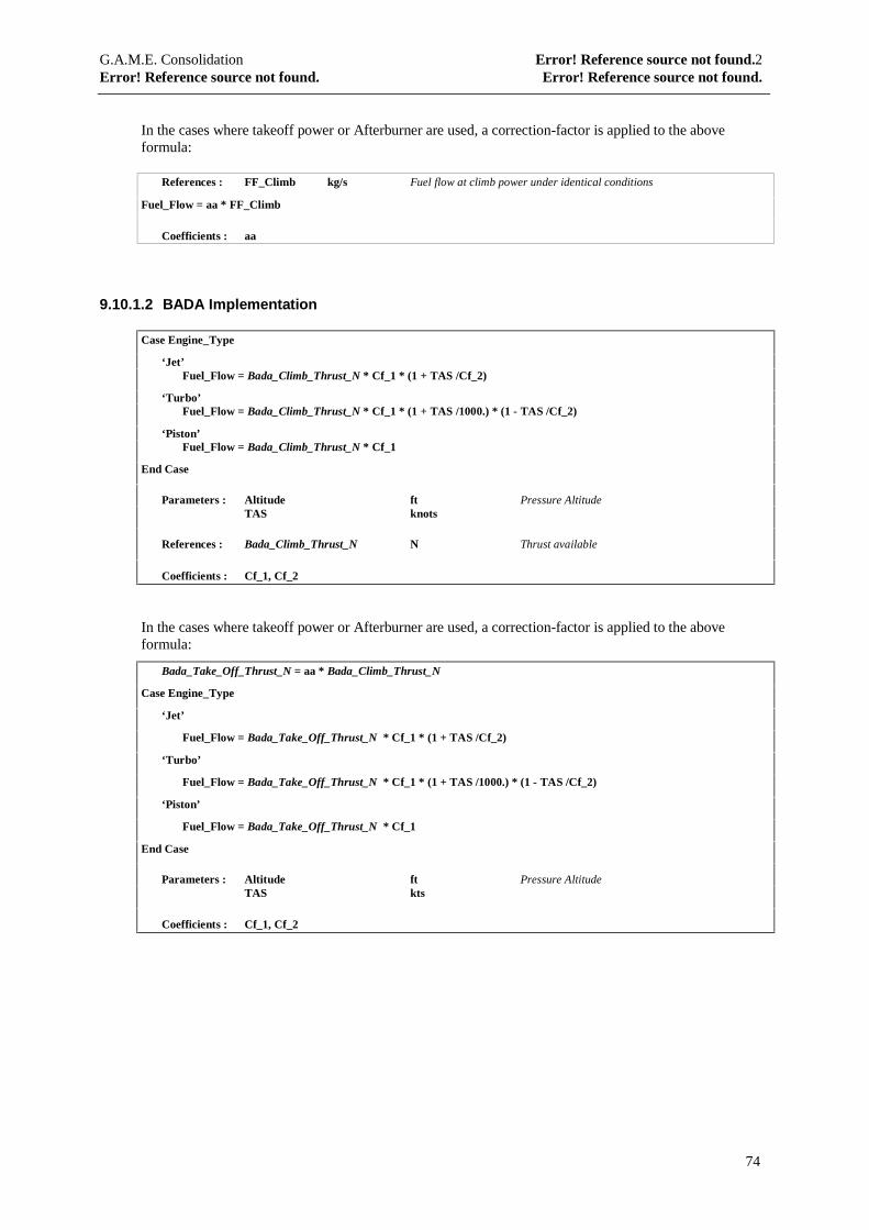
G.A.M.E. Consolidation Error! Reference source not found.2Error! Reference source not found. Error! Reference source not found.
74
In the cases where takeoff power or Afterburner are used, a correction-factor is applied to the aboveformula:
References : FF_Climb kg/s Fuel flow at climb power under identical conditions
Fuel_Flow = aa * FF_Climb
Coefficients : aa
9.10.1.2 BADA Implementation
Case Engine_Type
‘Jet’Fuel_Flow = Bada_Climb_Thrust_N * Cf_1 * (1 + TAS /Cf_2)
‘Turbo’Fuel_Flow = Bada_Climb_Thrust_N * Cf_1 * (1 + TAS /1000.) * (1 - TAS /Cf_2)
‘Piston’Fuel_Flow = Bada_Climb_Thrust_N * Cf_1
End Case
Parameters : Altitude ft Pressure AltitudeTAS knots
References : Bada_Climb_Thrust_N N Thrust available
Coefficients : Cf_1, Cf_2
In the cases where takeoff power or Afterburner are used, a correction-factor is applied to the aboveformula:
Bada_Take_Off_Thrust_N = aa * Bada_Climb_Thrust_N
Case Engine_Type
‘Jet’
Fuel_Flow = Bada_Take_Off_Thrust_N * Cf_1 * (1 + TAS /Cf_2)
‘Turbo’
Fuel_Flow = Bada_Take_Off_Thrust_N * Cf_1 * (1 + TAS /1000.) * (1 - TAS /Cf_2)
‘Piston’
Fuel_Flow = Bada_Take_Off_Thrust_N * Cf_1
End Case
Parameters : Altitude ft Pressure AltitudeTAS kts
Coefficients : Cf_1, Cf_2

G.A.M.E. Consolidation Error! Reference source not found.2Error! Reference source not found. Error! Reference source not found.
75
9.10.2 Idle Power.
In the same way as for climb-power, fuel consumption at idle-power is independent of the airframeconfiguration and of aircraft Mass. It is mainly influenced by air-temperature and density.
For jet aircraft, descending at idle power is standard procedure, and therefor Idle power consumption canbe directly used as the descent consumption. For propeller aircraft however, normal descent is executed ata constant rate of descent. This implies that the engines generate power, and therefor consumption duringdescent should be calculated using the method described under ‘Fuel Consumption for defined rates ofdescent’.
Item type Fuel_Flow
Unit kg / s kilograms per second
Configuration Independent from Aircraft configuration
Power setting Idle
API model / API_FUELFLOW_IDLE
9.10.2.1 GAME-implementation
Fuel_Flow = aa + bb*Altitude + cc*Altitude^2 + dd*CAS + ee*Diff_ISA
Parameters : Altitude ft Pressure AltitudeCAS ktsDiff_ISA °C difference between actual and standard temperature
Coefficients : aa, bb, cc, dd, ee
9.10.2.2 BADA-implementation
Idle thrust is calculated as described under 8.2.3.
References : BADA_Idle_Thrust_N N
Case Engine_Type
‘Jet’
Fuel_Flow = BADA_Idle_Thrust_N * Cf_1 * (1 + TAS /Cf_2)
‘Turbo’
Fuel_Flow = BADA_Idle_Thrust_N * Cf_1 * (1 + TAS /1000) * (1 - TAS /Cf_2)
‘Piston’
Fuel_Flow = BADA_Idle_Thrust_N * Cf_1
End Case
Parameters : Altitude ft Pressure AltitudeTAS kts
Coefficients : Cf_1, Cf_2
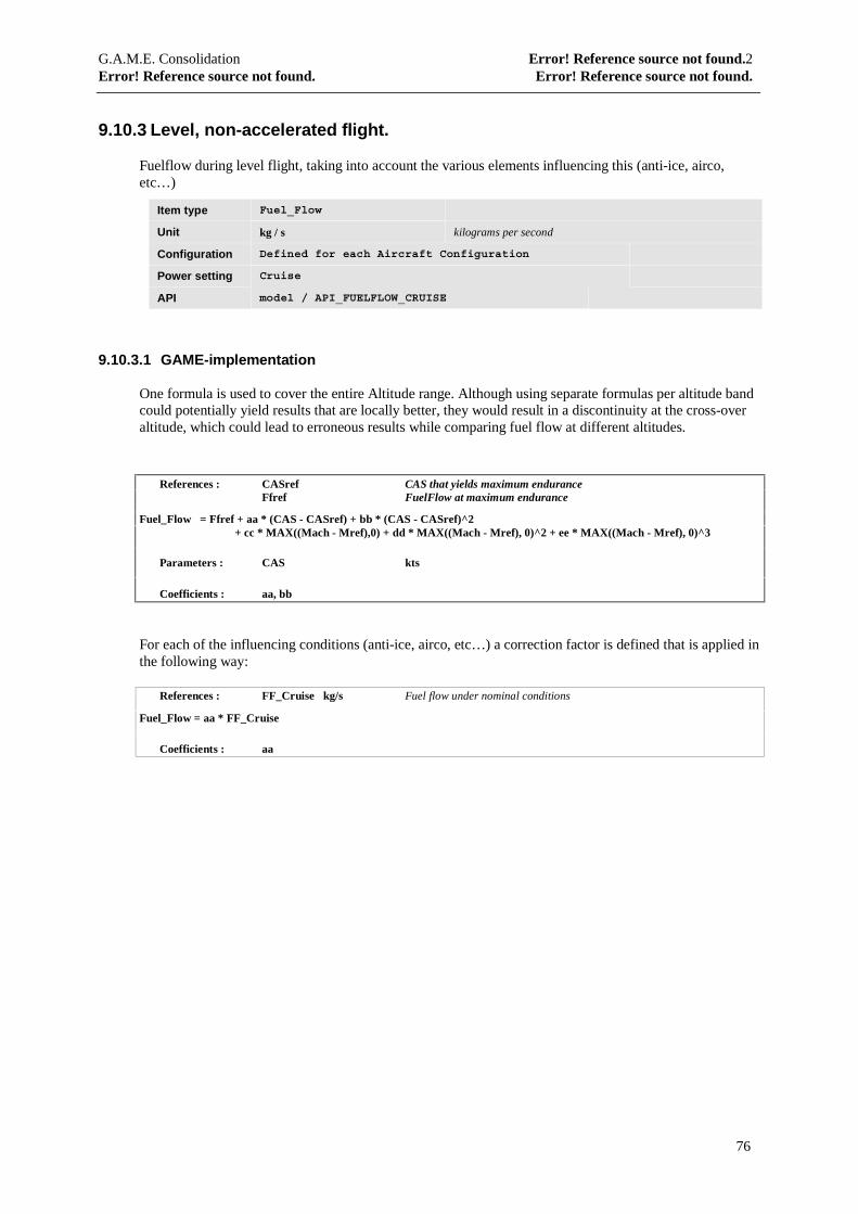
G.A.M.E. Consolidation Error! Reference source not found.2Error! Reference source not found. Error! Reference source not found.
76
9.10.3 Level, non-accelerated flight.
Fuelflow during level flight, taking into account the various elements influencing this (anti-ice, airco,etc…)
Item type Fuel_Flow
Unit kg / s kilograms per second
Configuration Defined for each Aircraft Configuration
Power setting Cruise
API model / API_FUELFLOW_CRUISE
9.10.3.1 GAME-implementation
One formula is used to cover the entire Altitude range. Although using separate formulas per altitude bandcould potentially yield results that are locally better, they would result in a discontinuity at the cross-overaltitude, which could lead to erroneous results while comparing fuel flow at different altitudes.
References : CASref CAS that yields maximum enduranceFfref FuelFlow at maximum endurance
Fuel_Flow = Ffref + aa * (CAS - CASref) + bb * (CAS - CASref)^2+ cc * MAX((Mach - Mref),0) + dd * MAX((Mach - Mref), 0)^2 + ee * MAX((Mach - Mref), 0)^3
Parameters : CAS kts
Coefficients : aa, bb
For each of the influencing conditions (anti-ice, airco, etc…) a correction factor is defined that is applied inthe following way:
References : FF_Cruise kg/s Fuel flow under nominal conditions
Fuel_Flow = aa * FF_Cruise
Coefficients : aa

G.A.M.E. Consolidation Error! Reference source not found.2Error! Reference source not found. Error! Reference source not found.
77
9.10.3.2 BADA Implementation
The BADA implementation uses the following formulas:
Drag as described in 8.2.1Thrust for Cruise is equal to drag.
References : Thrust = BADA_Drag_N
Case Engine_Type
‘Jet’
Fuel_Flow = Thrust * Cf_1 * (1 + TAS /Cf_2)
‘Turbo’
Fuel_Flow = Thrust * Cf_1 * (1 + TAS /1000) * (1 - TAS /Cf_2)
‘Piston’
Fuel_Flow = Thrust * Cf_1
End Case
Parameters : Altitude ft Pressure AltitudeFF kg/s Fuel flowTAS kts
Coefficients : Cf_1, Cf_2
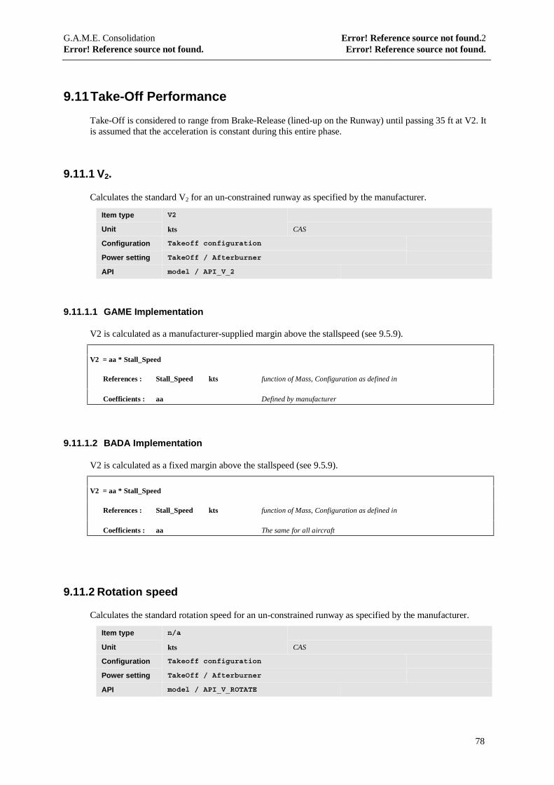
G.A.M.E. Consolidation Error! Reference source not found.2Error! Reference source not found. Error! Reference source not found.
78
9.11 Take-Off Performance
Take-Off is considered to range from Brake-Release (lined-up on the Runway) until passing 35 ft at V2. Itis assumed that the acceleration is constant during this entire phase.
9.11.1 V2.
Calculates the standard V2 for an un-constrained runway as specified by the manufacturer.
Item type V2
Unit kts CAS
Configuration Takeoff configuration
Power setting TakeOff / Afterburner
API model / API_V_2
9.11.1.1 GAME Implementation
V2 is calculated as a manufacturer-supplied margin above the stallspeed (see 9.5.9).
V2 = aa * Stall_Speed
References : Stall_Speed kts function of Mass, Configuration as defined in
Coefficients : aa Defined by manufacturer
9.11.1.2 BADA Implementation
V2 is calculated as a fixed margin above the stallspeed (see 9.5.9).
V2 = aa * Stall_Speed
References : Stall_Speed kts function of Mass, Configuration as defined in
Coefficients : aa The same for all aircraft
9.11.2 Rotation speed
Calculates the standard rotation speed for an un-constrained runway as specified by the manufacturer.
Item type n/a
Unit kts CAS
Configuration Takeoff configuration
Power setting TakeOff / Afterburner
API model / API_V_ROTATE
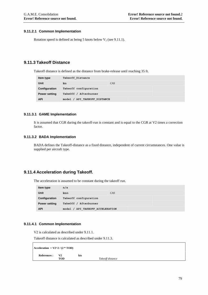
G.A.M.E. Consolidation Error! Reference source not found.2Error! Reference source not found. Error! Reference source not found.
79
9.11.2.1 Common Implementation
Rotation speed is defined as being 5 knots below V2 (see 9.11.1).
9.11.3 Takeoff Distance
Takeoff distance is defined as the distance from brake-release until reaching 35 ft.
Item type Takeoff_Distance
Unit kts CAS
Configuration Takeoff configuration
Power setting TakeOff / Afterburner
API model / API_TAKEOFF_DISTANCE
9.11.3.1 GAME Implementation
It is assumed that CGR during the takeoff-run is constant and is equal to the CGR at V2 times a correctionfactor.
9.11.3.2 BADA Implementation
BADA defines the Takeoff-distance as a fixed distance, independent of current circumstances. One value issupplied per aircraft type.
9.11.4 Acceleration during Takeoff.
The acceleration is assumed to be constant during the takeoff run.
Item type n/a
Unit kts/s CAS
Configuration Takeoff configuration
Power setting TakeOff / Afterburner
API model / API_TAKEOFF_ACCELERATION
9.11.4.1 Common Implementation
V2 is calculated as described under 9.11.1.
Takeoff distance is calculated as described under 9.11.3.
Acceleration = V2^2 / (2 * TOD)
References : V2 ktsTOD Takeoff distance
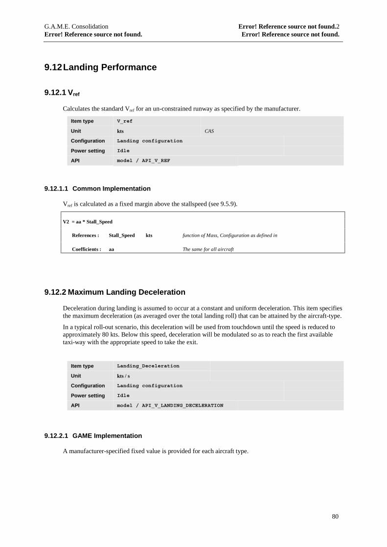
G.A.M.E. Consolidation Error! Reference source not found.2Error! Reference source not found. Error! Reference source not found.
80
9.12 Landing Performance
9.12.1 Vref
Calculates the standard Vref for an un-constrained runway as specified by the manufacturer.
Item type V_ref
Unit kts CAS
Configuration Landing configuration
Power setting Idle
API model / API_V_REF
9.12.1.1 Common Implementation
Vref is calculated as a fixed margin above the stallspeed (see 9.5.9).
V2 = aa * Stall_Speed
References : Stall_Speed kts function of Mass, Configuration as defined in
Coefficients : aa The same for all aircraft
9.12.2 Maximum Landing Deceleration
Deceleration during landing is assumed to occur at a constant and uniform deceleration. This item specifiesthe maximum deceleration (as averaged over the total landing roll) that can be attained by the aircraft-type.
In a typical roll-out scenario, this deceleration will be used from touchdown until the speed is reduced toapproximately 80 kts. Below this speed, deceleration will be modulated so as to reach the first availabletaxi-way with the appropriate speed to take the exit.
Item type Landing_Deceleration
Unit kts / s
Configuration Landing configuration
Power setting Idle
API model / API_V_LANDING_DECELERATION
9.12.2.1 GAME Implementation
A manufacturer-specified fixed value is provided for each aircraft type.
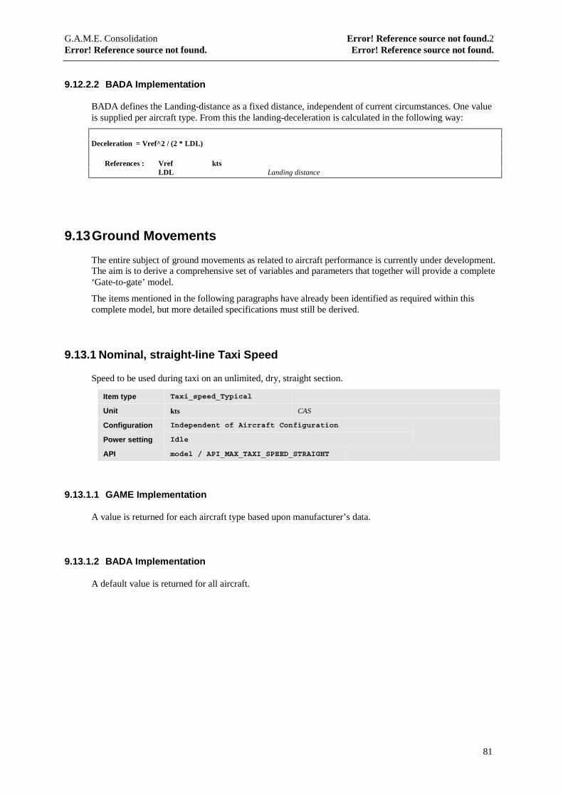
G.A.M.E. Consolidation Error! Reference source not found.2Error! Reference source not found. Error! Reference source not found.
81
9.12.2.2 BADA Implementation
BADA defines the Landing-distance as a fixed distance, independent of current circumstances. One valueis supplied per aircraft type. From this the landing-deceleration is calculated in the following way:
Deceleration = Vref^2 / (2 * LDL)
References : Vref ktsLDL Landing distance
9.13 Ground Movements
The entire subject of ground movements as related to aircraft performance is currently under development.The aim is to derive a comprehensive set of variables and parameters that together will provide a complete‘Gate-to-gate’ model.
The items mentioned in the following paragraphs have already been identified as required within thiscomplete model, but more detailed specifications must still be derived.
9.13.1 Nominal, straight-line Taxi Speed
Speed to be used during taxi on an unlimited, dry, straight section.
Item type Taxi_speed_Typical
Unit kts CAS
Configuration Independent of Aircraft Configuration
Power setting Idle
API model / API_MAX_TAXI_SPEED_STRAIGHT
9.13.1.1 GAME Implementation
A value is returned for each aircraft type based upon manufacturer’s data.
9.13.1.2 BADA Implementation
A default value is returned for all aircraft.
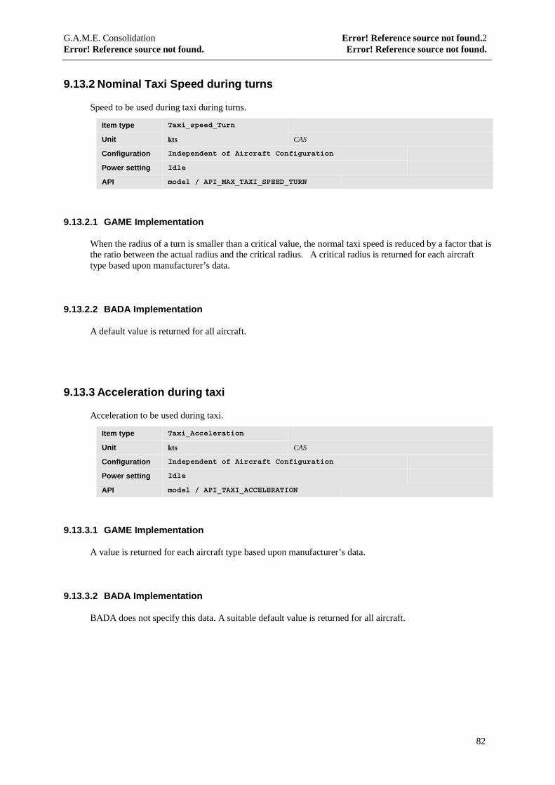
G.A.M.E. Consolidation Error! Reference source not found.2Error! Reference source not found. Error! Reference source not found.
82
9.13.2 Nominal Taxi Speed during turns
Speed to be used during taxi during turns.
Item type Taxi_speed_Turn
Unit kts CAS
Configuration Independent of Aircraft Configuration
Power setting Idle
API model / API_MAX_TAXI_SPEED_TURN
9.13.2.1 GAME Implementation
When the radius of a turn is smaller than a critical value, the normal taxi speed is reduced by a factor that isthe ratio between the actual radius and the critical radius. A critical radius is returned for each aircrafttype based upon manufacturer’s data.
9.13.2.2 BADA Implementation
A default value is returned for all aircraft.
9.13.3 Acceleration during taxi
Acceleration to be used during taxi.
Item type Taxi_Acceleration
Unit kts CAS
Configuration Independent of Aircraft Configuration
Power setting Idle
API model / API_TAXI_ACCELERATION
9.13.3.1 GAME Implementation
A value is returned for each aircraft type based upon manufacturer’s data.
9.13.3.2 BADA Implementation
BADA does not specify this data. A suitable default value is returned for all aircraft.

G.A.M.E. Consolidation Error! Reference source not found.2Error! Reference source not found. Error! Reference source not found.
83
9.13.4 Deceleration during taxi
Deceleration to be used during taxi.
Item type Taxi_Deceleration
Unit kts CAS
Configuration Independent of Aircraft Configuration
Power setting Idle
API model / API_TAXI_DECELERATION
9.13.4.1 GAME Implementation
A value is returned for each aircraft type based upon manufacturer’s data.
9.13.4.2 BADA Implementation
BADA does not specify this data. A suitable default value is returned for all aircraft.
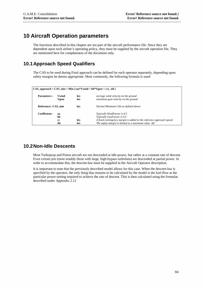
G.A.M.E. Consolidation Error! Reference source not found.2Error! Reference source not found. Error! Reference source not found.
84
10 Aircraft Operation parameters
The functions described in this chapter are not part of the aircraft performance file. Since they aredependent upon each airline’s operating policy, they must be supplied by the aircraft operation file. Theyare mentioned here for completeness of the document only.
10.1 Approach Speed Qualifiers
The CAS to be used during Final approach can be defined for each operator separately, depending uponsafety margins he deems appropriate. Most commonly, the following formula is used:
CAS_approach = CAS_min + Min ( (aa*Vwind + bb*Vgust + cc) , dd )
Parameters : Vwind kts average wind-velocity on the groundVgust kts maximum gust-velocity on the ground
References :CAS_min kts Normal Minimum CAS as defined above
Coefficients : aa Typically WindFactor is 0.5bb Typically GustFactor is 0.5cc kts A fixed contingency margin is added to the reference approach speed.dd kts The safety-margin is limited to a maximum value ‘dd’
10.2 Non-Idle Descents
Most Turboprop and Piston aircraft are not descended at idle-power, but rather at a constant rate of descent.Even certain jets (most notably those with large, high-bypass turbofans) are descended at partial power. Inorder to accommodate this, the descent-law must be supplied in the Aircraft Operator description.
It is important to note that the previously described model allows for this case. When the descent-law isspecified by the operator, the only thing that remains to be calculated by the model is the fuel-flow at theparticular power-setting required to achieve the rate of descent. This is then calculated using the formulasdescribed under Appendix 2.12
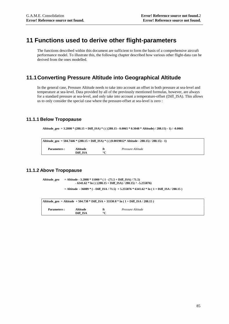
G.A.M.E. Consolidation Error! Reference source not found.2Error! Reference source not found. Error! Reference source not found.
85
11 Functions used to derive other flight-parameters
The functions described within this document are sufficient to form the basis of a comprehensive aircraftperformance model. To illustrate this, the following chapter described how various other flight-data can bederived from the ones modelled.
11.1 Converting Pressure Altitude into Geographical Altitude
In the general case, Pressure Altitude needs to take into account an offset in both pressure at sea-level andtemperature at sea-level. Data provided by all of the previously mentioned formulas, however, are alwaysfor a standard pressure at sea-level, and only take into account a temperature-offset (Diff_ISA). This allowsus to only consider the special case where the pressure-offset at sea-level is zero :
11.1.1 Below Tropopause
Altitude_geo = 3.2808 * (288.15 + Diff_ISA) * ( ( (288.15 - 0.0065 * 0.3048 * Altitude) / 288.15) - 1) / -0.0065
Altitude_geo = 504.7446 * (288.15 + Diff_ISA) * ( ( (0.0019812* Altitude - 288.15) / 288.15) - 1)
Parameters : Altitude ft Pressure AltitudeDiff_ISA °C
11.1.2 Above Tropopause
Altitude_geo = Altitude - 3.2808 * 11000 * ( 1 - (71.5 + Diff_ISA) / 71.5)- 6341.62 * ln ( ( (288.15 + Diff_ISA) / 288.15) ^ -5.255876)
= Altitude - 36089 * ( - Diff_ISA / 71.5) + 5.255876 * 6341.62 * ln ( 1 + Diff_ISA / 288.15 )
Altitude_geo = Altitude + 504.738 * Diff_ISA + 33330.8 * ln ( 1 + Diff_ISA / 288.15 )
Parameters : Altitude ft Pressure AltitudeDiff_ISA °C
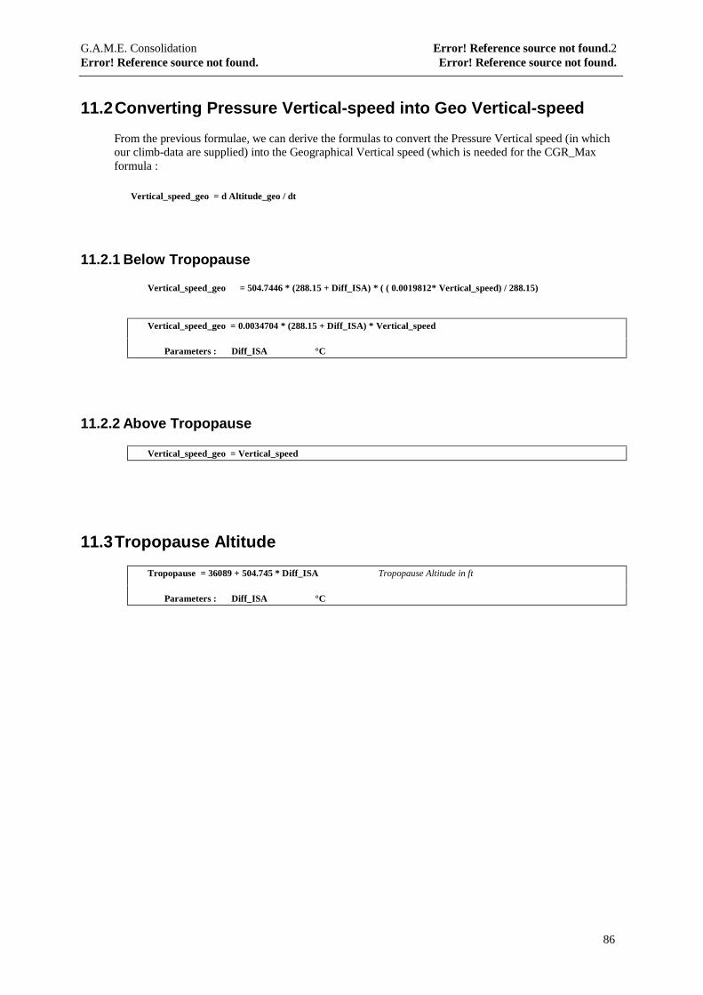
G.A.M.E. Consolidation Error! Reference source not found.2Error! Reference source not found. Error! Reference source not found.
86
11.2 Converting Pressure Vertical-speed into Geo Vertical-speed
From the previous formulae, we can derive the formulas to convert the Pressure Vertical speed (in whichour climb-data are supplied) into the Geographical Vertical speed (which is needed for the CGR_Maxformula :
Vertical_speed_geo = d Altitude_geo / dt
11.2.1 Below Tropopause
Vertical_speed_geo = 504.7446 * (288.15 + Diff_ISA) * ( ( 0.0019812* Vertical_speed) / 288.15)
Vertical_speed_geo = 0.0034704 * (288.15 + Diff_ISA) * Vertical_speed
Parameters : Diff_ISA °C
11.2.2 Above Tropopause
Vertical_speed_geo = Vertical_speed
11.3 Tropopause Altitude
Tropopause = 36089 + 504.745 * Diff_ISA Tropopause Altitude in ft
Parameters : Diff_ISA °C
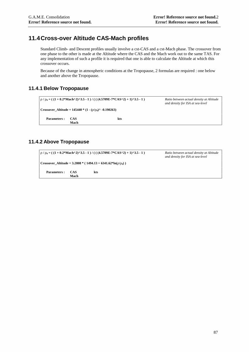
G.A.M.E. Consolidation Error! Reference source not found.2Error! Reference source not found. Error! Reference source not found.
87
11.4 Cross-over Altitude CAS-Mach profiles
Standard Climb- and Descent profiles usually involve a cst-CAS and a cst-Mach phase. The crossover fromone phase to the other is made at the Altitude where the CAS and the Mach work out to the same TAS. Forany implementation of such a profile it is required that one is able to calculate the Altitude at which thiscrossover occurs.
Because of the change in atmospheric conditions at the Tropopause, 2 formulas are required : one belowand another above the Tropopause.
11.4.1 Below Tropopause
ρ / ρ0 = ( (1 + 0.2*Mach^2)^3.5 - 1 ) / ( ( (4.5709E-7*CAS^2) + 1)^3.5 - 1 ) Ratio between actual density at Altitudeand density for ISA at sea-level
Crossover_Altitude = 145440 * (1 - (ρ/ρ0)^ -0.190263)
Parameters : CAS ktsMach
11.4.2 Above Tropopause
ρ / ρ0 = ( (1 + 0.2*Mach^2)^3.5 - 1 ) / ( ( (4.5709E-7*CAS^2) + 1)^3.5 - 1 ) Ratio between actual density at Altitudeand density for ISA at sea-level
Crossover_Altitude = 3.2808 * ( 1494.13 + 6341.62*ln(ρ/ρ0) )
Parameters : CAS ktsMach
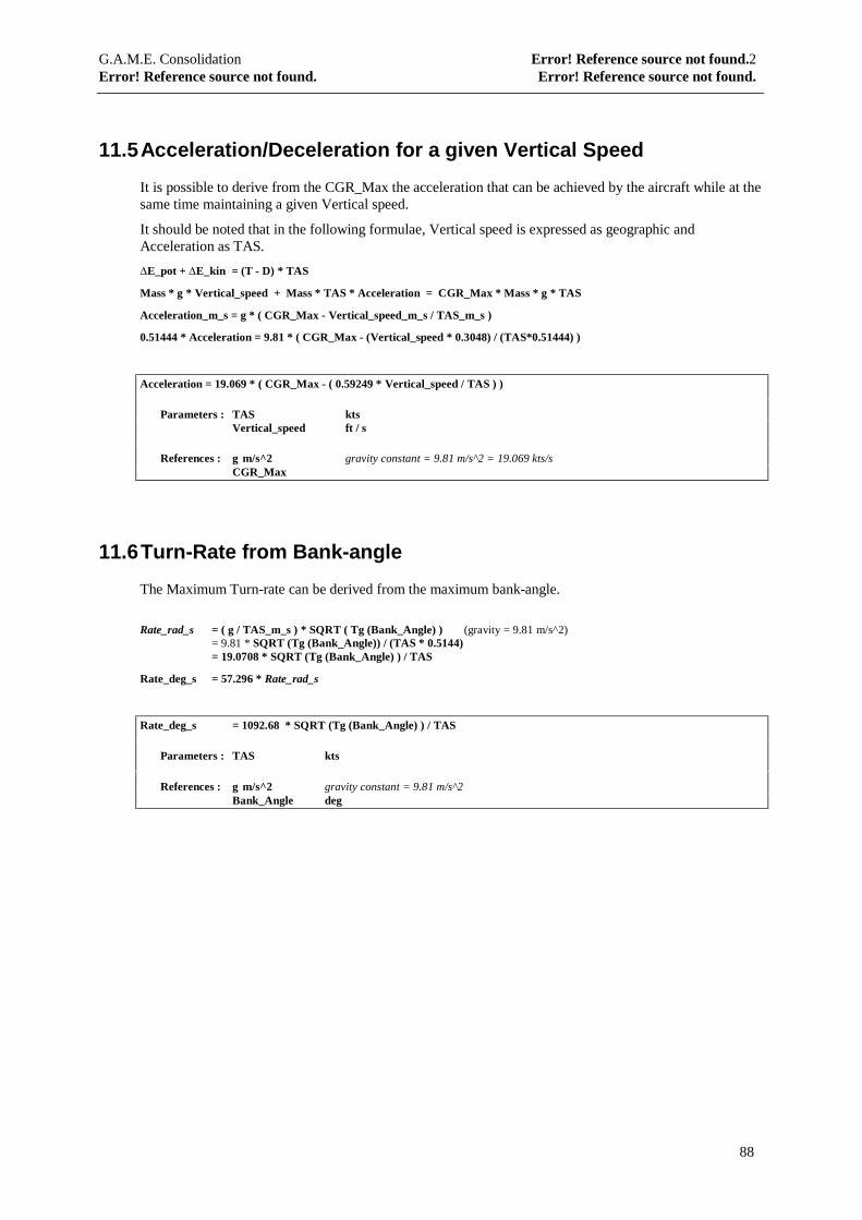
G.A.M.E. Consolidation Error! Reference source not found.2Error! Reference source not found. Error! Reference source not found.
88
11.5 Acceleration/Deceleration for a given Vertical Speed
It is possible to derive from the CGR_Max the acceleration that can be achieved by the aircraft while at thesame time maintaining a given Vertical speed.
It should be noted that in the following formulae, Vertical speed is expressed as geographic andAcceleration as TAS.
∆E_pot + ∆E_kin = (T - D) * TAS
Mass * g * Vertical_speed + Mass * TAS * Acceleration = CGR_Max * Mass * g * TAS
Acceleration_m_s = g * ( CGR_Max - Vertical_speed_m_s / TAS_m_s )
0.51444 * Acceleration = 9.81 * ( CGR_Max - (Vertical_speed * 0.3048) / (TAS*0.51444) )
Acceleration = 19.069 * ( CGR_Max - ( 0.59249 * Vertical_speed / TAS ) )
Parameters : TAS ktsVertical_speed ft / s
References : g m/s^2 gravity constant = 9.81 m/s^2 = 19.069 kts/sCGR_Max
11.6 Turn-Rate from Bank-angle
The Maximum Turn-rate can be derived from the maximum bank-angle.
Rate_rad_s = ( g / TAS_m_s ) * SQRT ( Tg (Bank_Angle) ) (gravity = 9.81 m/s^2)= 9.81 * SQRT (Tg (Bank_Angle)) / (TAS * 0.5144)= 19.0708 * SQRT (Tg (Bank_Angle) ) / TAS
Rate_deg_s = 57.296 * Rate_rad_s
Rate_deg_s = 1092.68 * SQRT (Tg (Bank_Angle) ) / TAS
Parameters : TAS kts
References : g m/s^2 gravity constant = 9.81 m/s^2Bank_Angle deg
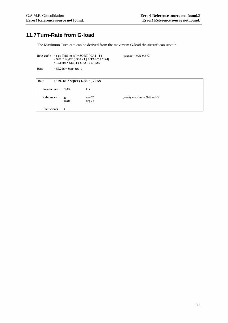
G.A.M.E. Consolidation Error! Reference source not found.2Error! Reference source not found. Error! Reference source not found.
89
11.7 Turn-Rate from G-load
The Maximum Turn-rate can be derived from the maximum G-load the aircraft can sustain.
Rate_rad_s = ( g / TAS_m_s ) * SQRT ( G^2 - 1 ) (gravity = 9.81 m/s^2)= 9.81 * SQRT ( G^2 - 1 ) / (TAS * 0.5144)= 19.0708 * SQRT ( G^2 - 1 ) / TAS
Rate = 57.296 * Rate_rad_s
Rate = 1092.68 * SQRT ( G^2 - 1 ) / TAS
Parameters : TAS kts
References : g m/s^2 gravity constant = 9.81 m/s^2Rate deg / s
Coefficients : G
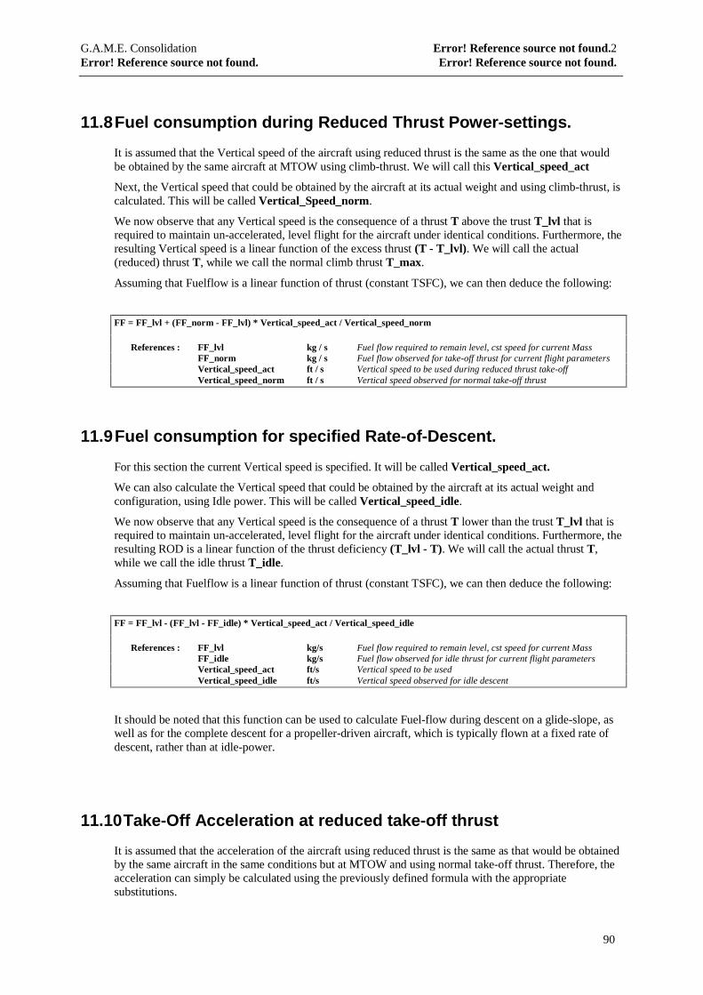
G.A.M.E. Consolidation Error! Reference source not found.2Error! Reference source not found. Error! Reference source not found.
90
11.8 Fuel consumption during Reduced Thrust Power-settings.
It is assumed that the Vertical speed of the aircraft using reduced thrust is the same as the one that wouldbe obtained by the same aircraft at MTOW using climb-thrust. We will call this Vertical_speed_act
Next, the Vertical speed that could be obtained by the aircraft at its actual weight and using climb-thrust, iscalculated. This will be called Vertical_Speed_norm.
We now observe that any Vertical speed is the consequence of a thrust T above the trust T_lvl that isrequired to maintain un-accelerated, level flight for the aircraft under identical conditions. Furthermore, theresulting Vertical speed is a linear function of the excess thrust (T - T_lvl). We will call the actual(reduced) thrust T, while we call the normal climb thrust T_max.
Assuming that Fuelflow is a linear function of thrust (constant TSFC), we can then deduce the following:
FF = FF_lvl + (FF_norm - FF_lvl) * Vertical_speed_act / Vertical_speed_norm
References : FF_lvl kg / s Fuel flow required to remain level, cst speed for current MassFF_norm kg / s Fuel flow observed for take-off thrust for current flight parametersVertical_speed_act ft / s Vertical speed to be used during reduced thrust take-offVertical_speed_norm ft / s Vertical speed observed for normal take-off thrust
11.9 Fuel consumption for specified Rate-of-Descent.
For this section the current Vertical speed is specified. It will be called Vertical_speed_act.
We can also calculate the Vertical speed that could be obtained by the aircraft at its actual weight andconfiguration, using Idle power. This will be called Vertical_speed_idle.
We now observe that any Vertical speed is the consequence of a thrust T lower than the trust T_lvl that isrequired to maintain un-accelerated, level flight for the aircraft under identical conditions. Furthermore, theresulting ROD is a linear function of the thrust deficiency (T_lvl - T). We will call the actual thrust T,while we call the idle thrust T_idle.
Assuming that Fuelflow is a linear function of thrust (constant TSFC), we can then deduce the following:
FF = FF_lvl - (FF_lvl - FF_idle) * Vertical_speed_act / Vertical_speed_idle
References : FF_lvl kg/s Fuel flow required to remain level, cst speed for current MassFF_idle kg/s Fuel flow observed for idle thrust for current flight parametersVertical_speed_act ft/s Vertical speed to be usedVertical_speed_idle ft/s Vertical speed observed for idle descent
It should be noted that this function can be used to calculate Fuel-flow during descent on a glide-slope, aswell as for the complete descent for a propeller-driven aircraft, which is typically flown at a fixed rate ofdescent, rather than at idle-power.
11.10 Take-Off Acceleration at reduced take-off thrust
It is assumed that the acceleration of the aircraft using reduced thrust is the same as that would be obtainedby the same aircraft in the same conditions but at MTOW and using normal take-off thrust. Therefore, theacceleration can simply be calculated using the previously defined formula with the appropriatesubstitutions.
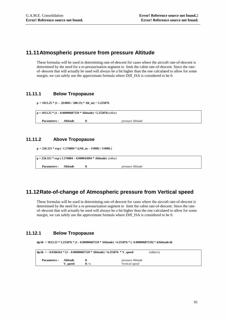
G.A.M.E. Consolidation Error! Reference source not found.2Error! Reference source not found. Error! Reference source not found.
91
11.11 Atmospheric pressure from pressure Altitude
These formulas will be used in determining rate-of-descent for cases where the aircraft rate-of-descent isdetermined by the need for a re-pressurisation segment to limit the cabin rate-of-descent. Since the rate-of–descent that will actually be used will always be a bit higher than the one calculated to allow for somemargin, we can safely use the approximate formula where Diff_ISA is considered to be 0.
11.11.1 Below Tropopause
p = 1013.25 * (1 – (0.0065 / 288.15) * Alt_m) ^ 5.255876
p = 1013.25 * (1 – 0.00000687559 * Altitude) ^5.255876 (mBar)
Parameters : Altitude ft pressure Altitude
11.11.2 Above Tropopause
p = 226.321 * exp ( -1.576884 * ((Alt_m – 11000) / 11000) )
p = 226.321 * exp ( 1.576884 – 0.000043694 * Altitude) (mBar)
Parameters : Altitude ft pressure Altitude
11.12 Rate-of-change of Atmospheric pressure from Vertical speed
These formulas will be used in determining rate-of-descent for cases where the aircraft rate-of-descent isdetermined by the need for a re-pressurisation segment to limit the cabin rate-of-descent. Since the rate-of–descent that will actually be used will always be a bit higher than the one calculated to allow for somemargin, we can safely use the approximate formula where Diff_ISA is considered to be 0.
11.12.1 Below Tropopause
dp/dt = 1013.25 * 5.255876 * (1 - 0.00000687559 * Altitude) ^4.255876 * (- 0.00000687559) * dAltitude/dt
dp/dt = - 0.0366161 * (1 – 0.00000687559 * Altitude) ^4.255876 * V_speed (mBar/s)
Parameters : Altitude ft pressure AltitudeV_speed ft / s Vertical speed
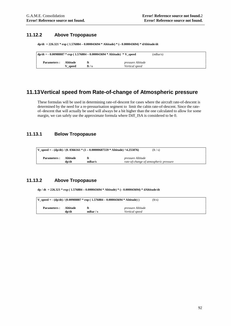
G.A.M.E. Consolidation Error! Reference source not found.2Error! Reference source not found. Error! Reference source not found.
92
11.12.2 Above Tropopause
dp/dt = 226.321 * exp ( 1.576884 – 0.000043694 * Altitude) * (– 0.000043694) * dAltitude/dt
dp/dt = - 0.00988887 * exp ( 1.576884 – 0.000043694 * Altitude) * V_speed (mBar/s)
Parameters : Altitude ft pressure AltitudeV_speed ft / s Vertical speed
11.13 Vertical speed from Rate-of-change of Atmospheric pressure
These formulas will be used in determining rate-of-descent for cases where the aircraft rate-of-descent isdetermined by the need for a re-pressurisation segment to limit the cabin rate-of-descent. Since the rate-of–descent that will actually be used will always be a bit higher than the one calculated to allow for somemargin, we can safely use the approximate formula where Diff_ISA is considered to be 0.
11.13.1 Below Tropopause
V_speed = - (dp/dt) / (0. 0366161 * (1 – 0.00000687559 * Altitude) ^4.255876) (ft / s)
Parameters : Altitude ft pressure Altitudedp/dt mBar/s rate-of-change of atmospheric pressure
11.13.2 Above Tropopause
dp / dt = 226.321 * exp ( 1.576884 – 0.000043694 * Altitude) * (– 0.000043694) * dAltitude/dt
V_speed = - (dp/dt) / (0.00988887 * exp ( 1.576884 – 0.000043694 * Altitude) ) (ft/s)
Parameters : Altitude ft pressure Altitudedp/dt mBar / s Vertical speed
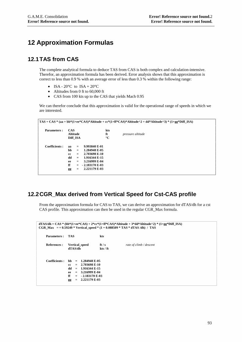
G.A.M.E. Consolidation Error! Reference source not found.2Error! Reference source not found. Error! Reference source not found.
93
12 Approximation Formulas
12.1 TAS from CAS
The complete analytical formula to deduce TAS from CAS is both complex and calculation-intensive.Therefor, an approximation formula has been derived. Error analysis shows that this approximation iscorrect to less than 0.9 % with an average error of less than 0.3 % within the following range:
• ISA - 20°C to ISA + 20°C• Altitudes from 0 ft to 60,000 ft• CAS from 100 kts up to the CAS that yields Mach 0.95
We can therefor conclude that this approximation is valid for the operational range of speeds in which weare interested.
TAS = CAS * (aa + bb*(1+ee*CAS)*Altitude + cc*(1+ff*CAS)*Altitude^2 + dd*Altitude^3) * (1+gg*Diff_ISA)
Parameters : CAS ktsAltitude ft pressure altitudeDiff_ISA °C
Coefficients : aa = 9.993840 E-01bb = 1.284948 E-05cc = 2.703698 E-10dd = 1.916344 E-15ee = 3.216999 E-04ff = - 2.183170 E-03gg = 2.221179 E-03
12.2 CGR_Max derived from Vertical Speed for Cst-CAS profile
From the approximation formula for CAS to TAS, we can derive an approximation for dTAS/dh for a cstCAS profile. This approximation can then be used in the regular CGR_Max formula.
dTAS/dh = CAS * (bb*(1+ee*CAS) + 2*cc*(1+ff*CAS)*Altitude + 3*dd*Altitude^2) * (1+gg*Diff_ISA)CGR_Max = = 0.59249 * Vertical_speed * (1 + 0.088509 * TAS * dTAS /dh) / TAS
Parameters : TAS kts
References : Vertical_speed ft / s rate of climb / descentdTAS/dh kts / ft
Coefficients : bb = 1.284948 E-05cc = 2.703698 E-10dd = 1.916344 E-15ee = 3.216999 E-04ff = - 2.183170 E-03gg = 2.221179 E-03
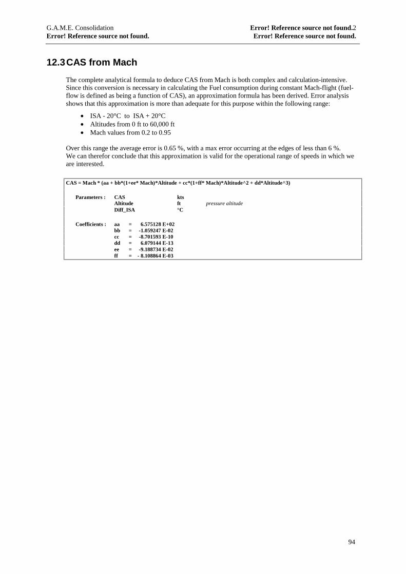
G.A.M.E. Consolidation Error! Reference source not found.2Error! Reference source not found. Error! Reference source not found.
94
12.3 CAS from Mach
The complete analytical formula to deduce CAS from Mach is both complex and calculation-intensive.Since this conversion is necessary in calculating the Fuel consumption during constant Mach-flight (fuel-flow is defined as being a function of CAS), an approximation formula has been derived. Error analysisshows that this approximation is more than adequate for this purpose within the following range:
• ISA - 20°C to ISA + 20°C• Altitudes from 0 ft to 60,000 ft• Mach values from 0.2 to 0.95
Over this range the average error is 0.65 %, with a max error occurring at the edges of less than 6 %.We can therefor conclude that this approximation is valid for the operational range of speeds in which weare interested.
CAS = Mach * (aa + bb*(1+ee* Mach)*Altitude + cc*(1+ff* Mach)*Altitude^2 + dd*Altitude^3)
Parameters : CAS ktsAltitude ft pressure altitudeDiff_ISA °C
Coefficients : aa = 6.575128 E+02bb = -1.059247 E-02cc = -8.701593 E-10dd = 6.079144 E-13ee = -9.188734 E-02ff = - 8.108864 E-03