Embed Size (px)
Citation preview
A
Report
On
MAGLEV TRAINSubmitted in partial fulfillment of award of degree of
Bachelor of Technology
in Electrical and Electronics
SUBMITTED BY:
ASHUTOSH PATHAK
Roll No. 1038221516
B.TECH 3RD YEAR
Supervisor
Mr. Shahab Ahmad1111111
Department Of Electrical And Electronics
Kamla Nehru Institute of Physical and Social Sciences,
Faridipur, Sultanpur-228118

CERTIFICATE
This is certified that seminar entitled “MAGLEV TRAIN” which is submitted by
Ms.GARIMA PATHAK, B.Tech (Third Year) Electrical and Electronics, is a partial
fulfillment towards the award of Degree of Bachelor of Technology in Electronics and
Communication Engg.
Ms. GARIMA PATHAK, B.Tech (Third Year), EN, has prepared the seminar under
my guidance in the session 2012-13 and delivered it successfully.
HOD Seminar In-
3333333
charge
Mr. RAJESH YADAV Mr. SHAHAB AHMAD
Electrical and Electronics Electrical and
Electronics
ACKNOWLEDGEMENT
I thank my seminar guide Mr. SHAHAB AHMAD, Lecturer, for his proper guidance,
and valuable suggestions. I am indebted to Mr. RAJESH YADAV, the HOD,
Electrical and Electronics division & other faculty members for giving me an
opportunity to learn and present the seminar on the topic "MAGLEV TRAIN". If
not for the above mentioned people my seminar would never have been completed
successfully. I once again extend my sincere thanks to all of them.
By
Date: 13 APRIL 2013 GARIMA PATHAK
Roll No. 1038221016
ABSTRACT
The objective of this project is to create a laboratory scale magnetic levitating train
model
using Inductrack technology developed by Dr. Richard Post from Lawrence Livermore
National Labs, Previous work by Paul Friend is discussed as well as the physics
associated
with Inductrack. The levitation and propulsion systems built in lab is described.
The conclusion includes the results and suggestions for future work on the
maglev train
The goal of the Magnetic Levitation Train (MAGLEV) project is to develop a small 5555555

scale
magnetic levitation train based on Inductrack technology developed by Dr. Richard
Post
from Lawrence Livermore National Labs (LLNL). This project is a continuation of
work
done by Paul Friend in 2004.
The MAGLEV project consists of two construction phases. Phase I proves that
levitation
is possible by redesign of a wheel track system. Phase II involves construction of an
oval
track to design and test a linear synchronous motor (LSM) for propulsion. Note that
Phases I & II are independent and thus can be done simultaneously.
TABLE OF CONTENT
INTRODUCTION
BASIC CONCEPT
TRACK
PROPULSION
INDUCTRACK TECHNOLOGY
SIMULATION
PREVIOUS WORK
LEVITATION
TRACK FABRICATION
ADVANTAGES
CONCLUSION
REFERENCES
7777777

INTRODUCTION
The Magnetic Levitation (Maglev) unit demonstrates closed loop levitation of
permanent and ferromagnetic elements. The plant consists of upper and lower coils
that produce a magnetic field in response to a DC current. A magnet (or sometimes
even two magnets) travels along a glass guide rod. By energizing the lower coil, a
single magnet is levitated through a repulsive magnetic force. As the current in the coil
increases, the field strength increases and the levitated magnet height is increased. For
the upper coil, the levitating force is attractive.
Up to two magnets may be controlled simultaneously by stacking them on the glass
rod. The magnets are of ultra-high field strength and are designed to provide large
levitated displacements to clearly demonstrate the principle of levitation and motion
control. Two laser-based sensors measure the magnet positions. The lower sensor is
typically used to measure a given magnet position in proximity to the lower coil, and
the upper one for proximity to the upper coil.
The unit can be set up in the stable and unstable (repulsive and attractive fields)
configurations. If two magnets and coils are used, the field interaction between the
magnets causes strong cross coupling and thus produces a true multivariable system.
Thus, magnets can be added or removed to provide single loop or multi-loop plants
that are stable or unstable. These configurations are illustrated in.
Most experiments deal with the so-called configuration1shown in Figures 5 and 6. It is
a configuration in which the lower magnet is levitated by exciting the lower
electromagnetic coil. The excitation of the lower electromagnet causes the repulsive
force on the magnetic disc. The repulsive force in turn levitates the magnetic disc. It is
a stable configuration.

9999999
Basic Concepts
Basic Concepts associated with MAGLEV are the Halbach Array, the Levitation
Track,
and the Propulsion system.
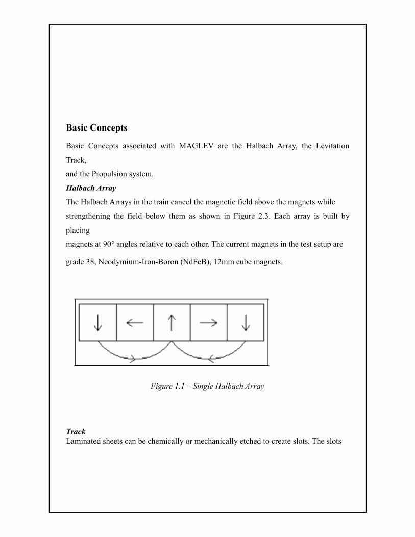
Halbach Array
The Halbach Arrays in the train cancel the magnetic field above the magnets while
strengthening the field below them as shown in Figure 2.3. Each array is built by
placing
magnets at 90° angles relative to each other. The current magnets in the test setup are
grade 38, Neodymium-Iron-Boron (NdFeB), 12mm cube magnets.
Figure 1.1 – Single Halbach Array
TrackLaminated sheets can be chemically or mechanically etched to create slots. The slots
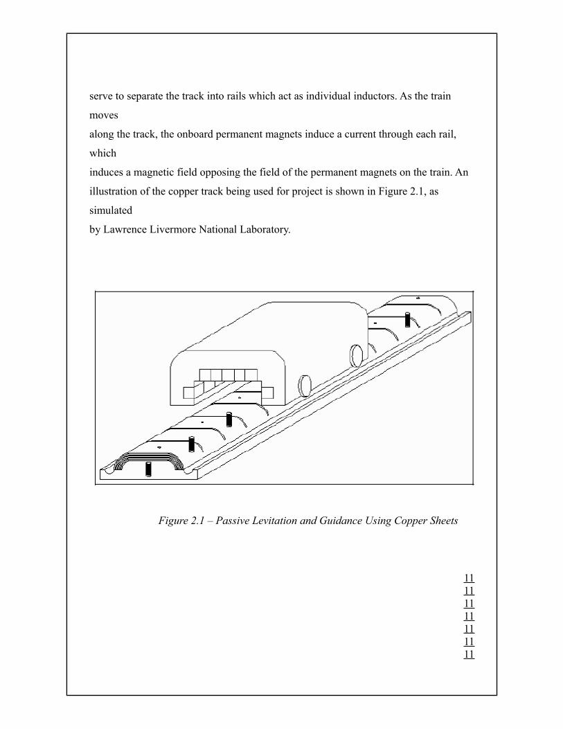
serve to separate the track into rails which act as individual inductors. As the train
moves
along the track, the onboard permanent magnets induce a current through each rail,
which
induces a magnetic field opposing the field of the permanent magnets on the train. An
illustration of the copper track being used for project is shown in Figure 2.1, as
simulated
by Lawrence Livermore National Laboratory.
Figure 2.1 – Passive Levitation and Guidance Using Copper Sheets
11111111111111
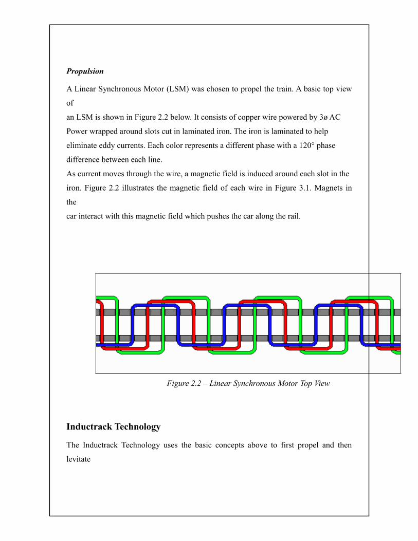
Propulsion
A Linear Synchronous Motor (LSM) was chosen to propel the train. A basic top view
of
an LSM is shown in Figure 2.2 below. It consists of copper wire powered by 3ø AC
Power wrapped around slots cut in laminated iron. The iron is laminated to help
eliminate eddy currents. Each color represents a different phase with a 120° phase
difference between each line.
As current moves through the wire, a magnetic field is induced around each slot in the
iron. Figure 2.2 illustrates the magnetic field of each wire in Figure 3.1. Magnets in
the
car interact with this magnetic field which pushes the car along the rail.
Figure 2.2 – Linear Synchronous Motor Top View
Inductrack Technology
The Inductrack Technology uses the basic concepts above to first propel and then
levitate

a train. The train consists of at least two sets of Halbach arrays. One set is placed over
the track to levitate the train, while the other set is placed above the motor to provide
propulsion.
When the motor is powered, the train begins to move on wheels along the track. The
levitation Halbach array induces current in the track which induces a magnetic field
around the slits to oppose the magnetic field of the levitation Halbach array. This
produces the levitation. The faster the train moves, the higher the train levitates. Paul
Friend’s research helped him plot levitation height vs. the velocity of the train as
shown
in Figure 4.1. In this example, the train reaches a peak height due to the lessened effect
of the magnets on the track. The height and velocity of the track are dependent on
parameters of the track and Halbach array.
13131313131313
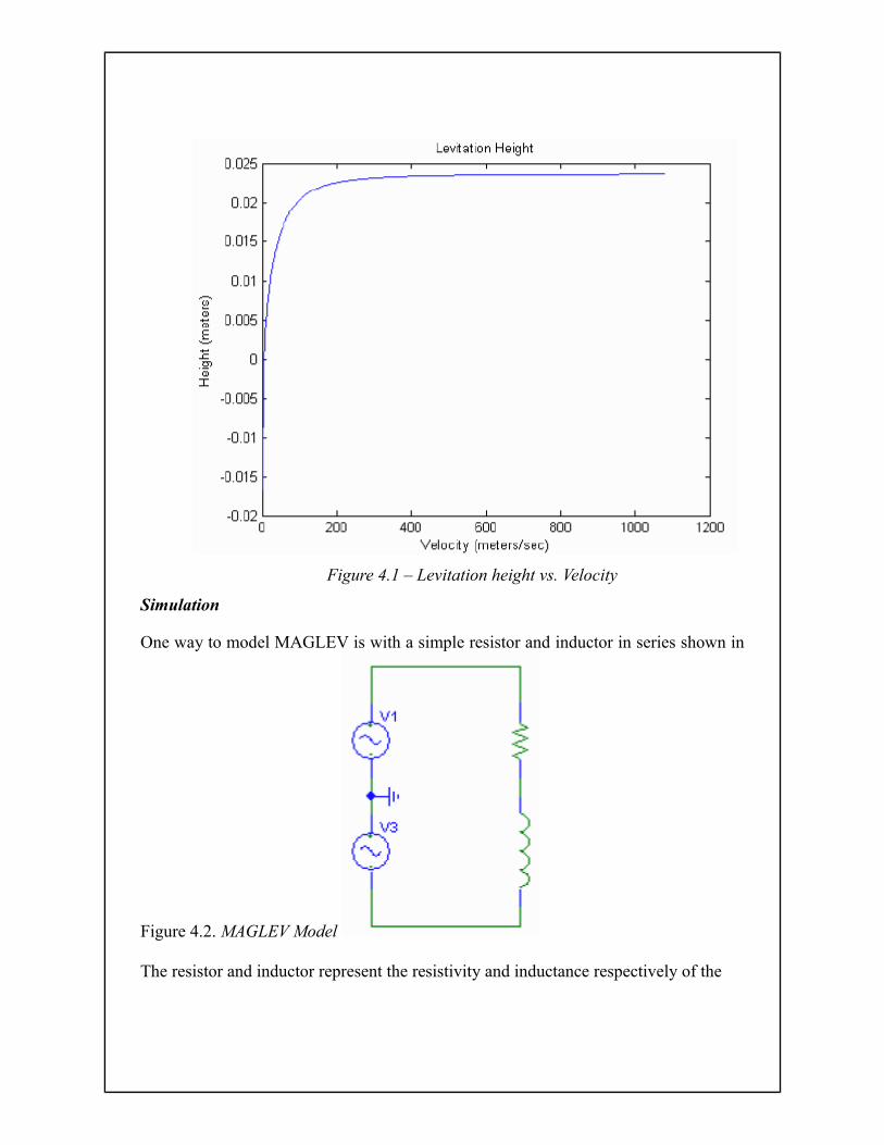
Figure 4.1 – Levitation height vs. Velocity
Simulation
One way to model MAGLEV is with a simple resistor and inductor in series shown in
Figure 4.2. MAGLEV Model
The resistor and inductor represent the resistivity and inductance respectively of the
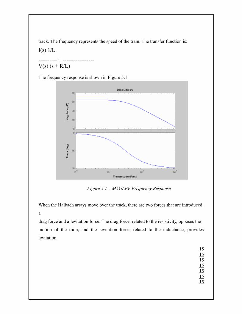
track. The frequency represents the speed of the train. The transfer function is:
I(s) 1/L
---------- = -----------------V(s) (s + R/L)
The frequency response is shown in Figure 5.1
Figure 5.1 – MAGLEV Frequency Response
When the Halbach arrays move over the track, there are two forces that are introduced:
a
drag force and a levitation force. The drag force, related to the resistivity, opposes the
motion of the train, and the levitation force, related to the inductance, provides
levitation.
15151515151515
The transfer function above illustrates that as the drag force begins to decrease, the
levitation force increases.
The phase shift relates to the drag forces becoming levitation forces. At 45° phase
(R/L
pole), levitation can be observed. Therefore it becomes extremely important to move
this
pole as close to zero as possible to provide levitation at lower speeds.
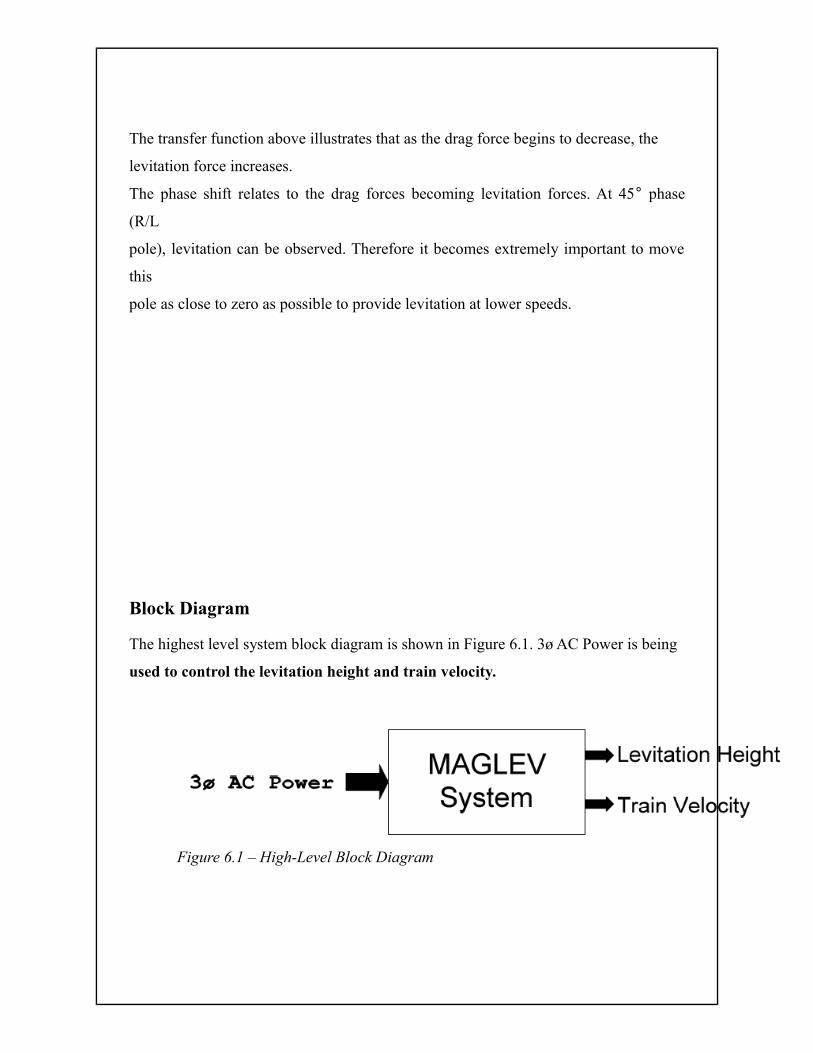
Block Diagram
The highest level system block diagram is shown in Figure 6.1. 3ø AC Power is being
used to control the levitation height and train velocity.
Figure 6.1 – High-Level Block Diagram
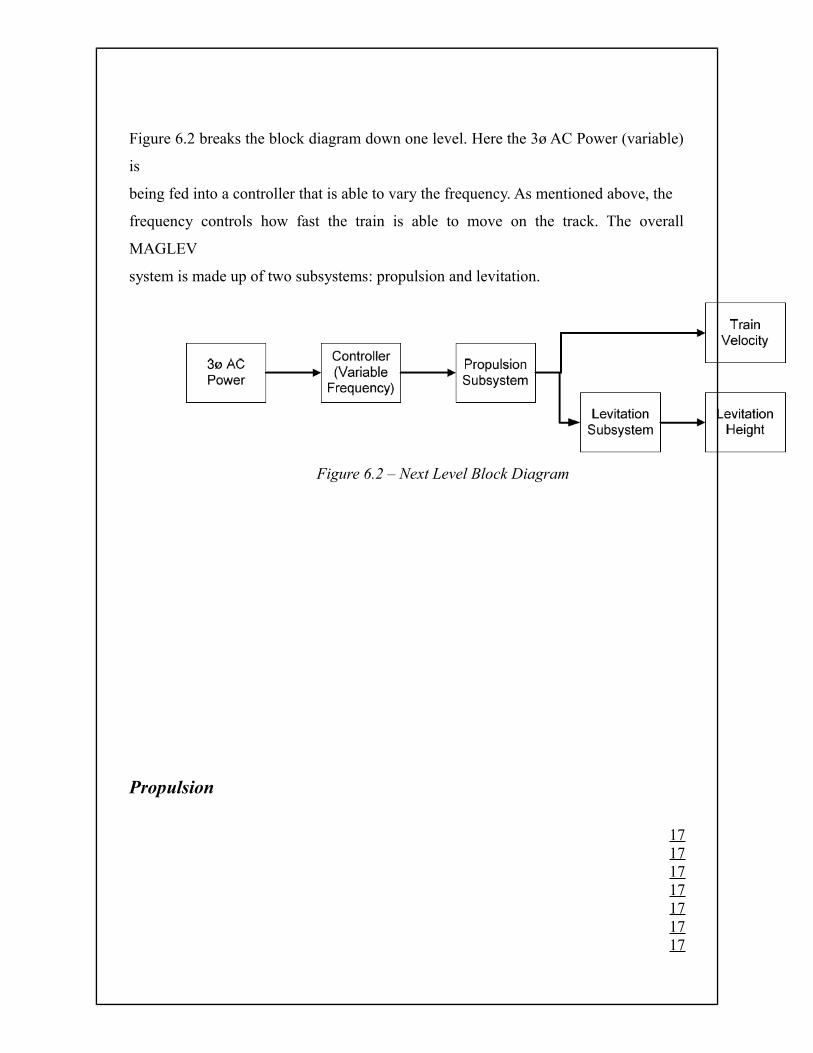
Figure 6.2 breaks the block diagram down one level. Here the 3ø AC Power (variable)
is
being fed into a controller that is able to vary the frequency. As mentioned above, the
frequency controls how fast the train is able to move on the track. The overall
MAGLEV
system is made up of two subsystems: propulsion and levitation.
Figure 6.2 – Next Level Block Diagram
Propulsion
17171717171717
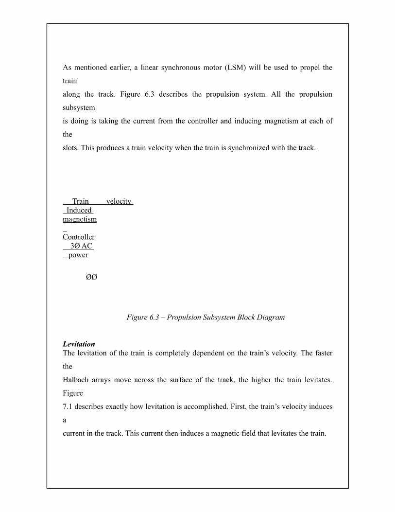
As mentioned earlier, a linear synchronous motor (LSM) will be used to propel the
train
along the track. Figure 6.3 describes the propulsion system. All the propulsion
subsystem
is doing is taking the current from the controller and inducing magnetism at each of
the
slots. This produces a train velocity when the train is synchronized with the track.
Train velocity Induced magnetism Controller 3 Ø AC power
ØØ
Figure 6.3 – Propulsion Subsystem Block Diagram
LevitationThe levitation of the train is completely dependent on the train’s velocity. The faster
the
Halbach arrays move across the surface of the track, the higher the train levitates.
Figure
7.1 describes exactly how levitation is accomplished. First, the train’s velocity induces
a
current in the track. This current then induces a magnetic field that levitates the train.
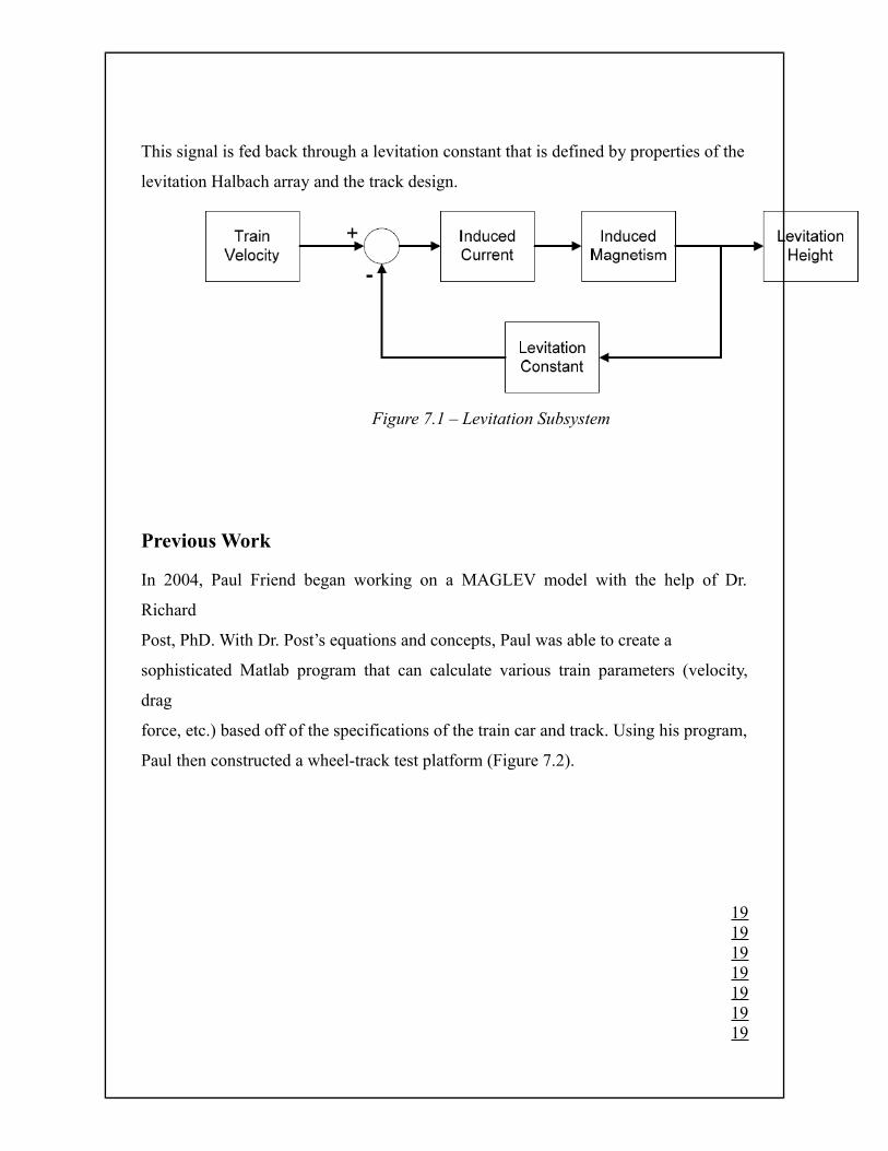
This signal is fed back through a levitation constant that is defined by properties of the
levitation Halbach array and the track design.
Figure 7.1 – Levitation Subsystem
Previous Work
In 2004, Paul Friend began working on a MAGLEV model with the help of Dr.
Richard
Post, PhD. With Dr. Post’s equations and concepts, Paul was able to create a
sophisticated Matlab program that can calculate various train parameters (velocity,
drag
force, etc.) based off of the specifications of the train car and track. Using his program,
Paul then constructed a wheel-track test platform (Figure 7.2).
19191919191919
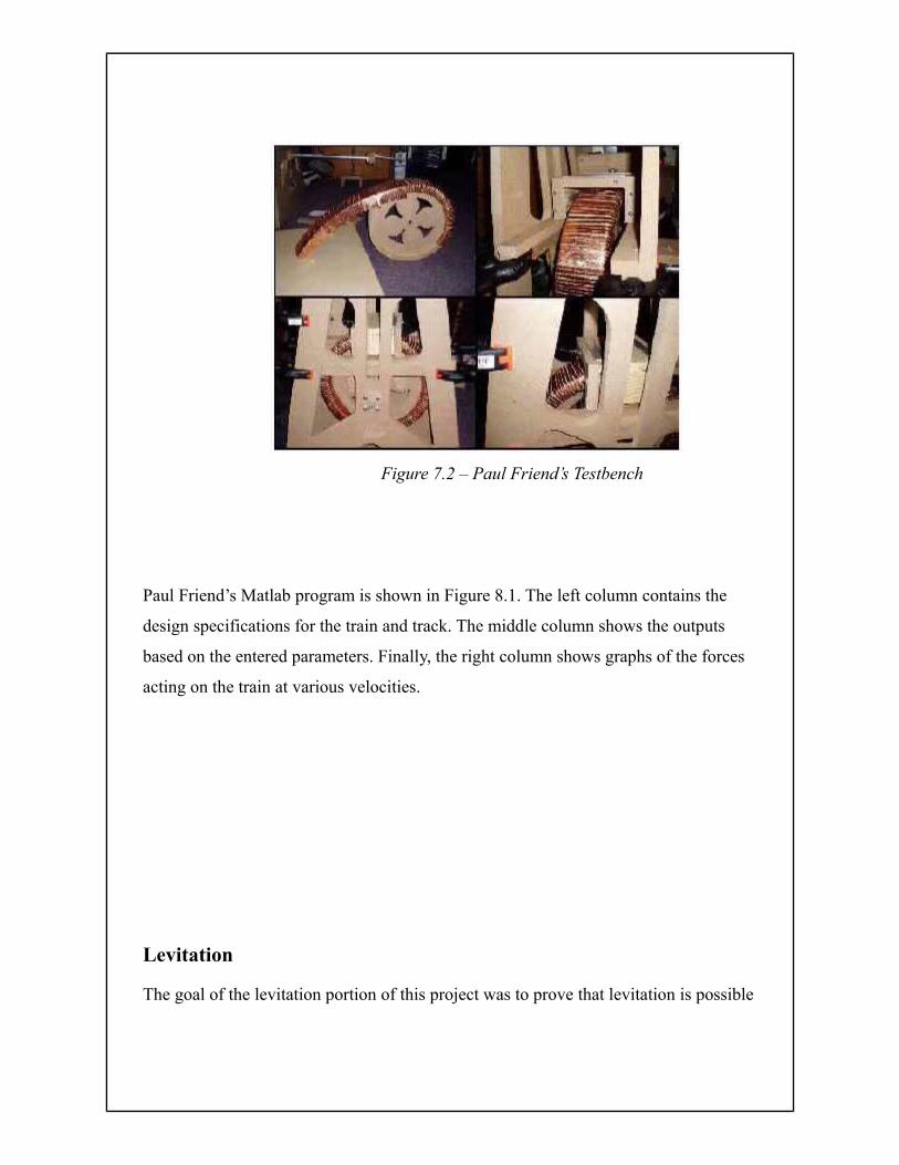
Figure 7.2 – Paul Friend’s Testbench
Paul Friend’s Matlab program is shown in Figure 8.1. The left column contains the
design specifications for the train and track. The middle column shows the outputs
based on the entered parameters. Finally, the right column shows graphs of the forces
acting on the train at various velocities.
Levitation
The goal of the levitation portion of this project was to prove that levitation is possible

and to optimize the track and train to get sufficient levitation at the lowest possible
speeds. The Matlab program was used to optimize the track and car parameters using
the
specifications of cost-effective materials. The design settled on provided 1cm of
levitation at about 9m/s. The following subsections will detail the design of the wheel
track test platform and car.
Wheel Fabrication
The wheel used was a 36” diameter racing bicycle tire, which had a standard sprocket
attached. Figure 9.1 shows the wheel and stand. The wheel was mounted on a
balancing
stand and attached to a motor with a gear and chain (Figure 9.3). With a goal of
achieving 9m/s, this means that the wheel (2 meter circumference) must spin at 270
rpm
if the train begins at less than 1cm above the track. This is necessary in order to
observe
any levitation. By using a chain and bicycle tire, an imbalanced track can still spin
smooth enough to get up to speeds greater than 1000 rpm.
21212121212121
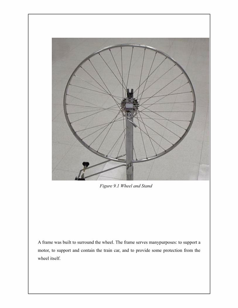
Figure 9.1 Wheel and Stand
A frame was built to surround the wheel. The frame serves manypurposes: to support a
motor, to support and contain the train car, and to provide some protection from the
wheel itself.
Track Fabrication
The track was created by Chicago WaterJet in Des Plaines, IL (Figure 10.1). Each of
the
5 strips measure 5cm wide and 1m long. The specifications were to have cuts made
ever
0.5cm with the cuts being 0.05cm wide and 4cm long (centered). However, the
smallest
width the waterjet process could create was 0.1cm, so this is how wide they are. The
track was cut from a 5ft x 3ft sheet of 0.021in thick aluminum sheet metal bought
from
Lowe’s Home Improvement.
23232323232323
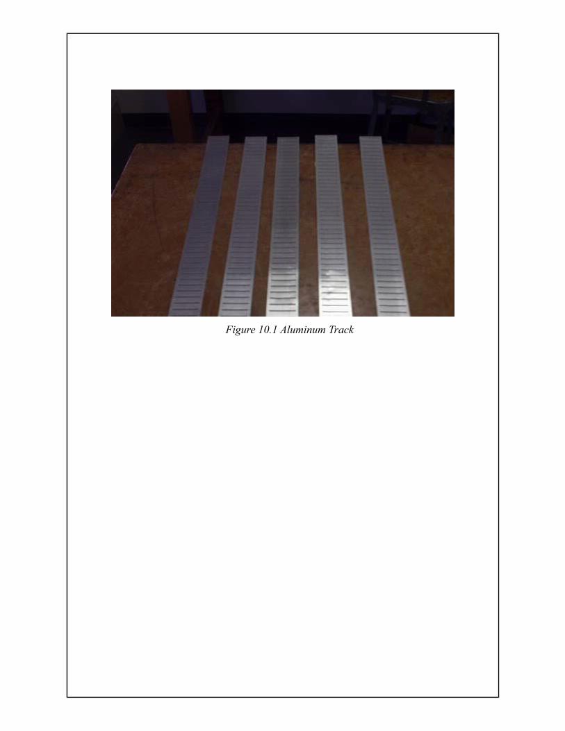
Figure 10.1 Aluminum Track

ADVANTAGES
Extraordinarily accurate – accuracy surpasses DNA matching
Very easy to use
Rapid recognition time
Perfectly safe (no laser is used )
A strong deterrent against fraud and misuse
Reduces administration costs
Scalable to a multi-million person database
Releases time for more productivity
Easily integrated into existing systems
Very low maintenance No need for PIN’s , cards and passwords
Non contact, non invasive
25252525252525
CONCLUSION
Great progress was made on both the levitation and propulsion systems of the
MAGLEV
project. This is the second time that students at Bradley University have constructed
the
pieces of a scale model, MAGLEV train. With each project comes a wealth of
information for the next students to digest before making their optimizations to the
design. We hope that our progress will see to it that one day Bradley will have a
workingscale model of a magnetic levitation train.
REFRENCES
[1] Dan’s Data. Rare Earth Magnets for Fun and Profit. October, 2004.
http://www.dansdata.com/magnets.htm
[2] Dan’s Data. Rare Earth Magnets 2! October, 2004.
http://www.dansdata.com/magnets.htm
[3] Engineering Concepts. Explanation of Magnet Ratings. November, 2005.
http://www.engconcepts.net/Magnet_Ratings.htm
[4] Friend, Paul. Final Report. May, 2004.
http://cegt201.bradley.edu/projects/proj2004/maglevt1/MaglevTrain1FinalReport.pdf
[5] Friend, Paul. Functional Description. November, 2003.
http://cegt201.bradley.edu/projects/proj2004/maglevt1/FUNCT%20DISC.pdf
[6] Friend, Paul. Project Proposal. December, 2003.
http://cegt201.bradley.edu/projects/proj2004/maglevt1/dproposal.pdf
27272727272727
[7] Friend, Paul. System Block Diagram. November, 2003.
http://cegt201.bradley.edu/projects/proj2004/maglevt1/Block%20Diagram.pdf
22
[8] Post, Richard F., Kratz, Robert, “Halbach Arrays for Maglev Applications,”
Lawrence Livermore National Laboratory. September 1999.
[9] Post, Richard F., “Inductrack Demonstration Model,” Report UCRL-ID-129664,
February 3, 1998.
[10] Post, Richard F., “Inductrack Magnet Configuration,” U.S. Patent No. 6,633,217
B2
[11] Post, Richard F., “Magnetic Levitation for Moving Objects,” U.S. Patent No.
5,722,326