Embed Size (px)
Citation preview

Leaders in Sealing Integrity
Garlock Metallic GasketsDesigned to withstand extremes


Garlock Metalllic Gaskets
Leaders in Sealing Integrity
3
CONTROLLED DENSITY™, TANDEM SEAL™, THERMa-PUR®, STABL-LOCK™ and G.E.T.™ are trademarks of Garlock
EDGE®, GRAPHONIC®, FLEXSEAL®, THERPHONIC®, and TEPHONIC® are registered trademarks of Garlock
CONTENTS Metallic Gasket StylesGasket Selection ...................................................................... 4
Spiral Wound Gaskets ............................................................. 5
The Garlock EDGE® Gasket ................................................. 6
HEAT SHIELD™ Gasket ........................................................ 7
TANDEM SEAL™ Gasket ..................................................... 8
FLEXSEAL® Family
RW, RWI, SW (For ASME flanges) ................................... 9
MCR (For boiler manholes) ............................................. 10
HH (For boiler handholes) ............................................... 11
RW-RJ, RWI-RJ (For ring joint flanges) .......................... 12
LMF (For large male/female flanges) .............................. 13
LTG (For large tongue and groove flanges)..................... 14
STG (For small tongue and groove flanges) ................... 14
Low-Load ........................................................................ 15
ULE (Ultra low Emissions) .............................................. 16
Metal-Clad Gasket Styles ...................................................... 18
Corrugated Metal Gaskets ..................................................... 20
GRAPHONIC® .................................................................... 20
TEPHONIC™ ....................................................................... 20
G.E.T.™................................................................................ 20
THERPHONIC® .................................................................. 20
Exchanger and Vessel Gaskets .............................................. 21
Heat Exchanger Gasket Configurations ............................. 21
Garlock Kammprofile Gasket ............................................. 22
Garlock Metallic Gaskets, a division of Garlock, manufactures spiral wound, serrated metal, metal clad, solid metal and metal core gaskets at its facility in Houston, Texas. This facility is registered to ISO-9001.
In recent years, Garlock Metallic Gaskets has introduced some of the industry’s most innovative production methods and products. For example, the CONTROLLED DENSITY™ process for spiral wound gaskets ensures a high tightness level at a lower bolt stress. The TANDEM SEAL™ combines chemical resistance and fire safety in a single gasket. The Garlock EDGE® gasket seals at lower bolt stress while virtually eliminating the problem of inward buckling. Various metal gaskets are now available with THERMa-PUR® for high temperature applications. Garlock Metallic Gaskets is also known for excellence in material and product quality as well as its outstanding customer service.
This catalog is provided for customer information and convenience. However, Garlock applications engineers are also on hand to assist you with your application requirements and technical questions. Please give us a call at 1-800-448-6688. We are here to serve you.
Engineering DataFactors Affecting Gasket Performance ................................. 23
Material Temperature Limits.................................................. 24
Thickness and Tolerances ...................................................... 24
Flange Types .......................................................................... 25
Recommended Flange Finish ................................................ 26 Maximum Bore ...................................................................... 27 Gasket Dimensions ............................................................... 28
Gasket Factors M and Y ........................................................ 37
Selection of Metals ................................................................ 38
Flange Rotation ...................................................................... 39
Gasket Installation ................................................................. 40
Torque Tables ......................................................................... 41
Troubleshooting Leaking Joints ............................................. 46
Ordering Guide ...................................................................... 47
Application Data Form ........................................................... 48
Conversions ........................................................................... 49
Garlock Metallic Gaskets

Garlock Metallic Gaskets
Leaders in Sealing Integrity
4
Gasket SelectionSPRIAL WOUND GASKETSOne of the best all-around seals, the spiral wound gasket offers a low-cost solution that has the ability to handle temperature and pressure fluctuations. Multiple plies of metal and filler in the spiral create a barrier that reduces the possibility of leaks.
TEMPERATURE AND CHEMICAL CONSIDERATIONSBe certain that the gasket you order is as resistant as possible to the media and temperature involved. Check the chemical compatibility of the metal as well as the filler material for the media to be sealed. As a general rule, the metal used in either the spiral winding or double-jacketed gasket should be similar to the flange material.
The compressibility of flexible graphite makes it an excellent filler material for metallic gaskets. Flexible graphite may be used in services with temperatures up to 850°F (450°C), though it should not be used with strong oxidizers such as nitric or sulfuric acid.
PTFE filler material provides excellent chemical resistance at temperatures below 500°F (260°C). In accordance with ASME B16.20, an inner ring is required when using conventional PTFE filler materials, in order to protect the winding from radial buckling.
See page 24 for the temperature limits of common metals and filler materials.
OPERATING PRESSUREOperating pressures have a direct effect on the construction and selection of metallic gaskets. Higher pressures raise the potential for gasket blowout, while lower pressure applications require a gasket design that seals under lower bolt loads.
Garlock gaskets suitable for high pressure include:
» Kammprofile gaskets
» Spiral wound gaskets with inner ring
» Solid metal gaskets
Low pressure gaskets include:
» GRAPHONIC® gaskets
» Garlock Kammprofile gaskets
» The Garlock EDGE® gasket
OTHER METAL GASKETSGarlock manufactures a wide variety of double-jacketed, spiral-wound, metal-clad and solid metal gaskets for heat exchanger and coker applications. GRAPHONIC® and Kammprofile gaskets are also available in heat exchanger configurations.
WARNING:Properties/applications shown throughout this brochure are typical. Your specific application should not be undertaken without independent study and evaluation for suitability. For specific application recommendations consult Garlock. Failure to select the proper sealing products could result in property damage and/or serious personal injury.
Performance data published in this brochure has been developed from field testing, customer field reports and/or in-house testing.
While the utmost care has been used in compiling this brochure, we assume no responsibility for errors. Specifications subject to change without notice. This edition cancels all previous issues. Subject to change without notice.

Garlock Metalllic Gaskets
Leaders in Sealing Integrity
5
Spiral Wound Gaskets
316L
Inner Ring MaterialPermanently Marked on Inner Ring
(when other than 304SS)
Manufacturer’s Name or Trademark
Manufactured to ASME B16.20
Nominal Pipe Size and Pressure Class
(standard gaskets only)
Permanently Marked on Outer Ring Material (when other than
Carbon Steel)
Outer (Centering) Ring
SpiralWinding & Filler
Material
Inner Ring
MANUFACTURED IN ACCORDANCE WITH ASME B16.20
Spiral wound gaskets—made with an alternating combination of formed metal wire and soft filler materials—form a very effective seal when compressed between two flanges. A v-shaped crown centered in the metal strip acts as a spring, giving gaskets greater resiliency under varying conditions. Filler and wire material can be changed to accommodate different chemical compatibility requirements. Fire safety can be assured by choosing flexible graphite as the filler material. If the load available to compress a gasket is limited, gasket construction and dimensions can be altered to provide an effective seal.
A spiral wound gasket may include a centering ring, an inner ring or both. The outer centering ring centers the gasket within the flange and acts as a compression limiter, while the inner ring provides additional radial strength. The inner ring also reduces flange erosion and protects the sealing element.
Resiliency and strength make spiral wound gaskets an ideal choice under a variety of conditions and applications. Widely used throughout refineries and chemical processing plants, spiral wound gaskets are also effective for power generation, pulp and paper, aerospace, and a variety of valve and specialty applications.
As set forth in ASME B16.20, all PTFE filled spiral wound gaskets will be supplied with inner rings. In addition, the following higher pressure class spirals will be supplied with inner rings for all filler material:
» NPS 24 and larger 900#
» NPS 12 and larger 1500#
» NPS 4 and larger 2500#
Starting in May 2008, the metricated edition of this standard recommends the use of inner rings for all graphite filled spiral wound gaskets. However, these gaskets may be specified without inner rings by the purchaser. Both styles will still be stamped ASME B16.20 compliant on the outer guide ring.
GASKET IDENTIFICATION MARKINGS REQUIRED BY ASME B16.20

Garlock Metallic Gaskets
Leaders in Sealing Integrity
6
The Garlock EDGE®
BENEFITSRequires lower seating stress » Seals at lower stress than conventional gaskets without an
inner ring
» Eliminates flange damage caused by overtightening
» Relief ports allow tighter seal at lower loads
Eliminates radial buckling » STABL-LOCK™ inner wrap construction prevents sealing
element from flowing into and contaminating process stream
Tightest seal » Modified guide ring ensures contact centered on raised face
flange surfaces*
Multiple applications » Available in a dual flange (DF) design to accommodate both
150# and 300# flanges
» Select from a wide variety of metallic and filler materials with a full range of temperature capabilities**
» Also available in HEAT SHIELD™ configuration for high temp services above 850°F.
Seals with lower bolt loads
» Relief tab design provides solid seating of centering ring face
» Withstands bolt load loss caused by thermal cycling
» Inner wrap construction eliminates radial buckling
» Prevents catastrophic failure and potential damage to downstream equipment due to wire unraveling
COMPARE
Standard spiral wound gasket shows excessive inward buckling
The patented Garlock EDGE® spiral wound gasket is designed to reduce inward buckling
DUAL FLANGE (DF) DESIGN
150# 300#
EDGE® DF
Flange
* Not intended for use on slip-on and many light weight lap joint flanges.** See chart on page 24.
Gasket Style & Material
"M" "Y" (psi)
Gb (psi)
"a" Gs (psi)
Garlock EDGE® with 304 stainless and fledible graphite filler
2.00 5,000 793 0.4 0.31

Garlock Metalllic Gaskets
Leaders in Sealing Integrity
7
HEAT SHIELD™ Gasket
BENEFITS » Fire safe and rated to 1250°F (677°C)
» Flexible graphite-filled spiral wound gasket has ID and OD filler plies of THERMa-PUR® or mica.
» THERMa-PUR® or mica layers protect the flexible graphite center from thermal oxidizing atmospheres
» Metal wire of the gasket can be made of a wide range of materials, depending upon the application
TYPICAL APPLICATIONS » Oxidizing environments
» Power plant steam drums
» Hydrocarbon processing catcrackers
» Chemical plant Oleflex units and ammonium nitrate service
» Hydrogen units, exhaust manifolds, and more.
CONSTRUCTION » Heat-resistant graphite filler
» Available with heat- and oxidation-resistant THERMa-PUR® or pure mica filler
» Spiral-wound wires of a choice of commercially available metals
» Rings of any standard metal, including INCONEL®* X750
Gasket Style & Material Gasket M Factor
Gasket Y Factor
Traditional spiral wound gasket 304SS and flexible graphite
3.00 10,000
Garlock CONTROLLED DENSITY™ spiral wound gasket
3.00 7,500
*Inconel is a registered trademark of Inco Alloys International, Inc.
The flexible graphite filled spiral wound gasket is widely used throughout chemical plants and refineries. Exceptional sealability and fire safety of this gasket make it superior to other types of spiral wound gaskets. It’s ideal for thermal oxidizing environments and provides a good choice for plant steam drums, hydrocarbon cat crackers, hydrogen units and exhaust manifolds.
Temperature, Max. 1250˚F (677˚C)
Flange Class 150# to 600#
Pipe diameters 2” to 24”, specials available
SPECIFICATIONS
NOTE:References made to particular applications are not a guarantee of acceptability of use for these services Contact Garlock for additional details and to discuss your particular application.
Wire
THERMa-PUR® or Mica Filler
THERMa-PUR® or Mica Filler
Flexible Graphite Filler

Garlock Metallic Gaskets
Leaders in Sealing Integrity
8
TANDEM SEAL™
BENEFITS
Chemical-resistant and fire-safe » PTFE envelope withstands aggressive chemicals and corrosive
media
» Fire-safe—passed independent fire tests
» Two sealing elements significantly reduce corrosion and bacterial contamination of flanges
» Seals to the ID of the pipe bore - specify pipe schedule when ordering
SEAL COMPARISON
Corrosion starts in blue area
TANDEM SEAL™ Design
Effectively seals to
bore of pipe
Media
Patent No. 5511797
Standard Gasket
Media
1. PTFE envelope
2. Kammprofile inner ring
3. Metal windings
1
SecondarySealing Element
PrimarySealing Element
2 3 4
5
STANDARD CONSTRUCTION
4. Filler material
5. Outer guide ring
1. Flexible Graphite or Expanded Teflon® Facing
2. Kammprofile inner ring
1
SecondarySealing Element
PrimarySealing Element
2 3 4 5
ALTERNATE CONSTRUCTION
3. Metal windings
4. Filler material
5. Outer guide ring
* Acid detecting paint also available

Garlock Metalllic Gaskets
Leaders in Sealing Integrity
9
FLEXSEAL® RW, RWI and SW GasketsADVANTAGES » Durable; easy installation and removal
» Seals pressures to flange ratings, in accordance with ASME B16.5 & B16.47
» Suitable for temperatures from cryogenic to 2,000°F (1,093°C)*
» Guide ring simplifies centering of sealing element on the flange face
» Designed solutions accommodate a variety of conditions by combining various metals and filler materials
STYLE RWI » Suitable for flat face and raised face flanges up to Class
2500#**
» Recommended for all gaskets, mandated for use with PTFE fillers, and when mandated by ASME B16.20 as follows: NPS 24 and larger in Class 900#, NPS 12 and larger in Class 1500#, and NPS 4 and larger in Class 2500#.
» Inner ring acts as compression limiter and protects sealing elements from process media attack
STYLE RW » General purpose gasket suitable for flat face and raised face
flanges up to Class 2500#**
» Centering ring accurately locates the gasket on the flange face, provides additional radial strength, and acts as a compression limiter
» Spiral winding (sealing element) consists of preformed metal and soft filler material
STYLE SW » Suitable for tongue and groove, male-female, or groove-to-flat
face flanges†
» Spiral winding only, containing preformed metal and soft filler material
» Also available with inner rings—Style SWI
NOTES: For M & Y factors, see page 37* Consult Garlock Engineering for material recommendations above 850˚ F (450˚C)** Depending on gasket size, an inner ring is recommended for applications above
Class 600#, due to the high available bolt load. See also Note 1 on page 27 .† This design does not have a compression limiter
Centering Ring
Spiral Winding (Sealing Element)
Centering Ring
Spiral Winding
Inner Ring
Winding Only
ORDERING INFORMATIONRW / RWIWhen ordering specify:
» Nominal pipe size or specific gasket dimensions
» Pressure rating
» Winding and filler materials
» Centering and/or inner compression ring material
SWWhen ordering, specify:
» O.D. and I.D. dimensions (and tolerance, if other than standard - see page 24)
» Thickness of gasket
» Pressure rating
» Winding and filler material
» Inner ring material, if required (Style SWI)

Garlock Metallic Gaskets
Leaders in Sealing Integrity
10
FLEXSEAL® MCR GasketMCR GASKET (manhole cover with centering ring)
» Centering ring accurately locates the gasket on the flange face, provides additional radial strength, and acts as a compression limiter
» Spiral winding (sealing element) consists of preformed metal and soft filler material
Centering Ring
Spiral Winding (Sealing Element)
ORDERING INFORMATION
When ordering, specify:
» Make and model of boiler and/or equipment if available (See chart page 11)
» Gasket style and configuration
» Dimensions of gasket (thickness, flange seating width, and shape)
» Maximum operating pressure and temperature
» Type of metal and filler materials
» Available in .175" and .250" thickness
WARNING:Properties/applications shown throughout this brochure are typical. Your specific application should not be undertaken without independent study and evaluation for suitability. For specific application recommendations consult Garlock. Failure to select the proper sealing products could result in property damage and/or serious personal injury.
Performance data published in this brochure has been developed from field testing, customer field reports and/or in-house testing.
While the utmost care has been used in compiling this brochure, we assume no responsibility for errors. Specifications subject to change without notice. This edition cancels all previous issues. Subject to change without notice.
MCR CONFIGURATIONS
Diameter
ROUND
OBROUND
Height
Width
OVAL
Height
Width
NOTES:1. For pitted and rough flange surfaces, specify a gasket thickness of
0.250".
2. Orders for special cover assemblies should be accompanied by a dimensional drawing showing the minimum width of seating surfaces and other essential dimensions.
3. Orders for non-standard gaskets should also include a sketch or drawing of the cover assembly with all dimensions shown.

Garlock Metalllic Gaskets
Leaders in Sealing Integrity
11
FLEXSEAL® HH GasketFOR BOILER HANDHOLE AND TUBECAP ASSEMBLIES
» Fits most standard boilers (specify maximum operating pressure when ordering)
» Available in thicknesses of 0.125" (special), 0.175" (standard) and 0.250" (special —for pitted surfaces)
STYLE HH CONFIGURATIONS
RECTANGLE
DIAMOND
PEAR
Height
Width
R
Width
HeightR
Width
RR
ORDERING INFORMATION
When ordering, specify:
» Make and model of boiler and/or equipment, if available
» Gasket style and configuration
» Dimensions of gasket (thickness, flange seating width, and shape)
» Maximum operating pressure and temperature
» Type of metal and filler materials
WARNING:Properties/applications shown throughout this brochure are typical. Your specific application should not be undertaken without independent study and evaluation for suitability. For specific application recommendations consult Garlock. Failure to select the proper sealing products could result in property damage and/or serious personal injury.
Performance data published in this brochure has been developed from field testing, customer field reports and/or in-house testing.
While the utmost care has been used in compiling this brochure, we assume no responsibility for errors. Specifications subject to change without notice. This edition cancels all previous issues. Subject to change without notice.
BOILER GASKET DIMENSIONS
ROUND
OBROUND
OVAL
Diameter
Height
Width
Height
Width
Manufacturer & Model No. Shape
Nominal I.D.Dimensions
(Inches)
Flange Width
(Inches)
Babcock and Wilcox
#40 (207) Diamond 3-3/8 x 3-3/4 3/16
#48 (208) Oval 3-3/16 x 4-3/4 7/32
#24 (211) Oval 4-1/2 x 5-1/2 7/32
#47 Round 2-1/32 3/16
#70 Round 3-9/32 3/16
#28 (212) Rectangle 4-13/16 x 5 7/32
Badenhausen
(See Riley Stoker)
Cleaver-Brooks Obround 3-9/32 x 4-17/32 3/8
Combustion Engr.
29N-L839 Diamond 3-3/8 x 4-1/4 1/4
4N-L740 Round 3-1/8 1/4
5N-L902 Round 3-5/8 1/4
Foster Wheeler
2-3/4 (1003) Obround 2-25/32 x 3-13/32 7/32
3-15/16 (1005) Oval 4-3/16 x 5-3/16 5/16
Heine Round 3-5/8 3/8
Keeler Obround 3 x 4 3/8
Oilfield Oval 3 x 4 3/8
Oval 3-1/2 x 4-1/2 3/8
Riley Stoker W-C2 Obround 3-23/32 x 5-23/32 11/32
Springfield Oval 3-17/32 x 4-17/32 5/16
Union Oval 3 x 4 3/8
Pear 4-1/4 x 5-1/4 3/8
Vogt Oval 4-1/4 x 5-1/8 7/32 (new)
Wickes
Pear 4-1/8 x 5-1/8 9/32
D2300 Oval 3 x 4 5/16
D2301 Oval 3-1/2 x 4-1/2 5/16

Garlock Metallic Gaskets
Leaders in Sealing Integrity
12
FLEXSEAL® RW-RJ, RWI-RJ Gaskets
FOR REPLACEMENT OF RING JOINT GASKETS
» Ideal replacement for solid metal oval or octagonal API ring joint gaskets (RTJ)
» Saves cost of flange replacement when gasket groove is badly worn
» Fast and easy installation—requires only a 3/16" flange separation (ring joint gasket may require as much as 3/4")
» Wide variety of metal and filler materials have a full range of temperature and pressure capabilities
† Suitable for slip-on and weld neck type flanges* 150# - 400#: for weld neck type flanges having a pipe bore equal to that of schedule 40 pipe. Not for slip-on flanges.
Nominal
Pipe Size (Inches)
150# 300# 400# Gasket Ring Gasket Ring Gasket Ring
I.D. O.D. O.D. I.D. O.D. O.D. I.D. O.D. O.D.1/2 — — — 9/16 1-1/16 2-1/8 9/16 1-1/16 2-1/8
3/4 — — 13/16 1-5/16 2-5/8 13/16 1-5/16 2-5/8
1 1-1/8* 1-5/8* 2-5/8* 1-1/16 1-5/8 2-7/8 1-1/16 1-5/8 2-7/8
1-1/4 1-3/8* 1-7/8* 3* 1-5/16 2 3-1/4 1-5/16 2 3-1/4
1-1/2 1-5/8* 2-1/4* 3-3/8* 1-9/16 2-3/8 3-3/4 1-9/16 2-3/8 3-3/4
2 2-1/8* 2-7/8* 4-1/8* 2-1/8 2-3/4 4-3/8 2-1/8 2-3/4 4-3/8
2-1/2 2-3/4* 3-5/16* 4-7/8* 2-3/4 3-5/16 5-1/8 2-3/4 3-5/16 5-1/8
3 3-5/16* 3-15/16* 5-3/8* 3-5/16 3-15/16 5-7/8 3-5/16 3-15/16 5-7/8
4 4-5/16* 5-3/16* 6-7/8* 4-5/16 5-3/16 7-1/8 4-5/16 5-3/16 7
5 5-5/16* 6-3/16* 7-3/4* 5-5/16 6-7/16 8-1/2 5-5/16 6-7/16 8-3/8
6 6-5/16* 7-3/16* 8-3/4* 6-7/16 7-5/8 9-7/8 6-7/16 7-5/8 9-3/4
8 8-1/4* 9-3/16* 11* 8-1/4 9-15/16 12-1/8 8-1/4 9-15/16 12
10 10-5/16* 11-7/16* 13-3/8* 10-5/16 12 14-1/4 10-5/16 12 14-1/8
12 12-3/16* 13-9/16* 16-1/8* 12-7/8† 14-1/4† 16-5/8† 12-7/8† 14-1/4† 16-1/2†
14 13-7/16* 14-15/16* 17-3/4* 14-1/4† 15-3/4† 19-1/8† 14-1/4† 15-3/4† 19†
16 15-5/16* 16-15/16* 20-1/4* 16-1/4† 17-3/4† 21-1/4† 16-1/4† 17-3/4† 21-1/8†
18 17-1/4* 19* 21-5/8* 18-1/4† 20-1/4† 23-1/2† 18-1/4† 20-1/4† 23-3/8†
20 19-1/8* 21-1/8 20-1/4† * 23-7/8* 22-3/16† 25-3/4 22-3/16† † 20-1/4† 25-1/2†
24 23* 25-1/4* 28-1/4* 24-1/4† 26-5/16† 30-1/2† 24-1/4† 26-5/16† 30-1/4†
Dimensions for weld neck type flanges having a pipe bore equal to that of schedule 40 pipe and heavier, but not for slip-on flanges; exceptions noted below.

Garlock Metalllic Gaskets
Leaders in Sealing Integrity
13
Nominal
Pipe Size (Inches)
600# 900# 1500# Gasket Ring Gasket Ring Gasket Ring
I.D. O.D. O.D. I.D. O.D. O.D. I.D. O.D. O.D.
1/2 9/16 1-1/16 2-1/8 9/16* 1-1/16* 2-1/2* 9/16* 1-1/16* 2-1/2*
3/4 13/16 1-5/16 2-5/8 13/16* 1-3/8* 2-3/4* 13/16* 1-3/8* 2-3/4*
1 1-1/16 1-5/8 2-7/8 1-1/16* 1-5/8* 3-1/8* 1-1/16* 1-5/8* 3-1/8*
1-1/4 1-5/16 2 3-1/4 1-5/16* 2* 3-1/2* 1-5/16* 2* 3-1/2*
1-1/2 1-9/16 2-3/8 3-3/4 1-9/16* 2-3/8* 3-7/8* 1-9/16* 2-3/8* 3-7/8*
2 2-1/8 2-3/4 4-3/8 2-1/4* 3-1/4* 5-5/8* 2-1/4* 3-1/4* 5-5/8*
2-1/2 2-3/4 3-5/16 5-1/8 2-9/16* 3-5/8* 6-1/2* 2-9/16* 3-5/8* 6-1/2*
3 3-5/16 3-15/16 5-7/8 3-3/16* 4-3/16* 6-5/8* 3-3/16* 4-11/16* 6-7/8*
4 4-5/16 5-3/16 7-5/8 4-1/16* 5-3/16* 8-1/8* 4-1/16* 5-11/16* 8-1/4*
5 5-5/16 6-7/16 9-1/2 5-5/16 6-7/16 9-3/4 5-1/16* 6-15/16* 10*
6 6-7/16 7-5/8 10-1/2 6-5/16 7-5/8 11-3/8 6* 7-9/16* 11-1/8*
8 8-1/4 9-15/16 12-5/8 8-1/4 9-15/16 14-1/8 7-7/8* 9-3/4* 13-7/8*
10 10-5/16 12 15-3/4 10-5/16 12 17-1/8 9-13/16* 11-7/8* 17-1/8*
12 12-7/8† 14-1/4† 18† 12-7/8 14-1/4 19-5/8 11-15/16* 13-13/16* 20-1/2*
14 14-1/4† 15-3/4† 19-3/8† 13-13/16 15-9/16 20-1/2 13-7/16 15-3/16 22-3/4
16 16-1/4† 17-3/4† 22-1/4† 15-9/16 17-9/16 22-5/8 15 17 25-1/4
18 18-1/4† 20-1/4† 24-1/8† 17-11/16 19-15/16 25-1/8 17-1/4 19-1/2 27-3/4
20 20-1/4† 22-3/16† 26-7/8† 19-11/16 21-15/16 27-1/2 19-3/16 21-7/16 29-3/4
24 24-1/4† 26-5/16† 31-1/8† 23-3/16 25-15/16 33 23 25-1/2 35-1/2
† Suitable for slip-on and weld neck type flanges * 600# - 1500#: for schedule 80 pipe and heavier.
Dimensions for weld neck type flanges having a pipe bore equal to that of schedule 40 pipe and heavier, but not for slip-on flanges; exceptions noted below.

Garlock Metallic Gaskets
Leaders in Sealing Integrity
14
FLEXSEAL® LMF, LTG and STG Gaskets
Cross Sectional View of Winding
FOR MALE-FEMALE, TONGUE AND GROOVE FLANGES
» Spiral winding of preformed metal and soft filler material —for use where no space is provided for a compression guide ring
» Inner Diameter of windings is reinforced with several plies of metal without filler to give greater stability
» Style LMF - large male-female flanges Style LTG - large tongue and groove flanges Style STG - small tongue and groove flanges
APPLICATIONS
» Valves » Heat exchangers » Pumps » Vessels » Flanges
WARNING:Properties/applications shown throughout this brochure are typical. Your specific application should not be undertaken without independent study and evaluation for suitability. For specific application recommendations consult Garlock. Failure to select the proper sealing products could result in property damage and/or serious personal injury.
Performance data published in this brochure has been developed from field testing, customer field reports and/or in-house testing.
While the utmost care has been used in compiling this brochure, we assume no responsibility for errors. Specifications subject to change without notice. This edition cancels all previous issues. Subject to change without notice.
ORDERING INFORMATION
When ordering, specify: » Nominal pipe size » Pressure rating » Winding materials (304 SS is standard, filler material must be
specified) » Thickness of winding (0.125" is standard)
STYLE LMF GASKET DIMENSIONS
Nominal Pipe Size(Inches)
150# - 1500# 2500#
I.D. (Inches)
O.D. (Inches)
I.D. (Inches
O.D. (Inches
1/2 1 1-3/8 13/16 1-3/8
3/4 1-5/16 1-11/16 1-1/16 1-11/16
1 1-1/2 2 1-1/4 2
1-1/4 1-7/8 2-1/2 1-5/8 2-1/2
1-1/2 2-1/8 2-7/8 1-7/8 2-7/8
2 2-7/8 3-5/8 2-3/8 3-5/8
2-1/2 3-3/8 4-1/8 3 4-1/8
3 4-1/4 5 3-3/4 5
3-1/2 4-3/4 5-1/2 — —
4 5-3/16 6-3/16 4-3/4 6-3/16
5 6-5/16 7-5/16 5-3/4 7-5/16
6 7-1/2 8-1/2 6-3/4 8-1/2
8 9-3/8 10-5/8 8-3/4 10-5/8
10 11-1/4 12-3/4 10-3/4 12-3/4
12 13-1/2 15 13 15
14 14-3/4 16-1/4 — —
16 17 18-1/2 — —
18 19-1/4 21 — —
20 21 23 — —
24 25-1/4 27-1/4 — —
Nominal Pipe Size(Inches)
150# - 1500#
I.D. (Inches)
O.D. (Inches)
1/2 1 1-3/8
3/4 1-5/16 1-11/16
1 1-1/2 2
1-1/4 1-7/8 2-1/2
1-1/2 2-1/8 2-7/8
2 2-7/8 3-5/8
2-1/2 3-3/8 4-1/8
3 4-1/4 5
3-1/2 4-3/4 5-1/2
4 5-3/16 6-3/16
5 6-5/16 7-5/16
6 7-1/2 8-1/2
8 9-3/8 10-5/8
10 11-1/4 12-3/4
12 13-1/2 15
14 14-3/4 16-1/4
16 17 18-1/2
18 19-1/4 21
20 21 23
24 25-1/4 27-1/4
STYLE LTG GASKET DIMENSIONS
Nominal Pipe Size(Inches)
150# - 1500#
I.D. (Inches)
O.D. (Inches)
1/2 1 1-3/8
3/4 1-5/16 1-11/16
1 1-1/2 1-7/8
1-1/4 1-7/8 2-1/4
1-1/2 2-1/8 2-1/2
2 2-7/8 3-1/4
2-1/2 3-3/8 3-3/4
3 4-1/4 4-5/8
3-1/2 4-3/4 5-1/8
4 5-3/16 5-11/16
5 6-5/16 6-13/16
6 7-1/2 8
8 9-3/8 10
10 11-1/4 12
12 13-1/2 14-1/4
14 14-3/4 15-1/2
16 16-3/4 17-5/8
18 19-1/4 20-1/8
20 21 22
24 25-1/4 26-1/4
STYLE STG GASKET DIMENSIONS
Garlock Metalllic Gaskets
Leaders in Sealing Integrity
15
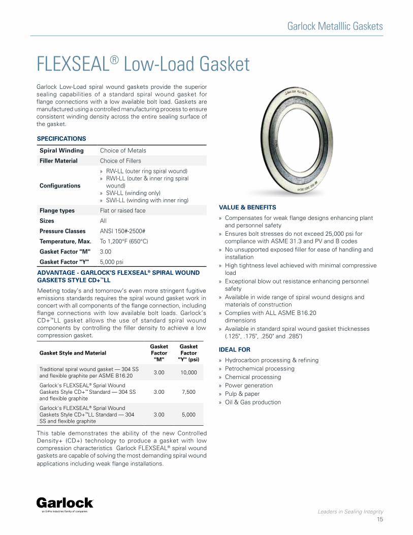
FLEXSEAL® Low-Load GasketGarlock Low-Load spiral wound gaskets provide the superior sealing capabilities of a standard spiral wound gasket for flange connections with a low available bolt load. Gaskets are manufactured using a controlled manufacturing process to ensure consistent winding density across the entire sealing surface of the gasket.
SPECIFICATIONS
Spiral Winding Choice of Metals
Filler Material Choice of Fillers
Configurations
» RW-LL (outer ring spiral wound) » RWI-LL (outer & inner ring spiral
wound) » SW-LL (winding only) » SWI-LL (winding with inner ring)
Flange types Flat or raised face
Sizes All
Pressure Classes ANSI 150#-2500#
Temperature, Max. To 1,200°F (650°C)
Gasket Factor "M" 3.00
Gasket Factor "Y" 5,000 psi
VALUE & BENEFITS
» Compensates for weak flange designs enhancing plant and personnel safety
» Ensures bolt stresses do not exceed 25,000 psi for compliance with ASME 31.3 and PV and B codes
» No unsupported exposed filler for ease of handling and installation
» High tightness level achieved with minimal compressive load
» Exceptional blow out resistance enhancing personnel safety
» Available in wide range of spiral wound designs and materials of construction
» Complies with ALL ASME B16.20 dimensions
» Available in standard spiral wound gasket thicknesses (.125", .175", .250" and .285")
IDEAL FOR
» Hydrocarbon processing & refining » Petrochemical processing » Chemical processing » Power generation » Pulp & paper » Oil & Gas production
ADVANTAGE - GARLOCK'S FLEXSEAL® SPIRAL WOUND GASKETS STYLE CD+™LL
Meeting today’s and tomorrow’s even more stringent fugitive emissions standards requires the spiral wound gasket work in concert with all components of the flange connection, including flange connections with low available bolt loads. Garlock’s CD+™LL gasket allows the use of standard spiral wound components by controlling the filler density to achieve a low compression gasket.
This table demonstrates the ability of the new Controlled Density+ (CD+) technology to produce a gasket with low compression characteristics Garlock FLEXSEAL® spiral wound gaskets are capable of solving the most demanding spiral wound applications including weak flange installations.
Gasket Style and MaterialGasket Factor "M"
Gasket Factor
"Y" (psi)
Traditional spiral wound gasket — 304 SS and flexible graphite per ASME B16.20
3.00 10,000
Garlock's FLEXSEAL® Sprial Wound Gaskets Style CD+™ Standard — 304 SS and flexible graphite
3.00 7,500
Garlock's FLEXSEAL® Sprial Wound Gaskets Style CD+™LL Standard — 304 SS and flexible graphite
3.00 5,000

Garlock Metallic Gaskets
Leaders in Sealing Integrity
16
Garlock has expanded their ULE (Ultra Low Emissions) family of products to include a spiral wound gasket. The FLEXSEAL® ULE is designed for use where leakage control is critical and the aggressive application requires a spiral wound design. It’s manufactured using high performance graphite, and offers maximum protection against oxidation. The standard design includes an inner ring and outer ring, as well as preformed metal wire to enhance compressability and sealability. The FLEXSEAL® ULE spiral wound is another product born from Garlock’s customer driven innovation.
VALUES AND BENEFITS
» API 6FB › Average leak rate recorded of 1.4 ml/min
» Low Emissions (CFET) › Provides average leakage rates of 10 PPM (parts per million)
» Oxidation Resistance › Offers maximum protection against oxidation for greater
reliability and longer service life
› No aging or fatigue under dynamic load, even at elevated temperatures
» Manufacturability › Available in standard lead-time
CONFIGURATIONS
» Available in
› Standard Flexseal Spiral Wound configurations: RW/RWI/SW/SWI
› Materials and dimensions per ASME B16.20
› Materials available include various series 300 stainless, Hastelloy®*, Inconel®** and titanium, custom materials are also available
IDEAL FOR
» Thermal Cycling - Compressibility and recovery of high performance graphite combined with custom winding technology and processes that provides excellent chemical resistance and performance operating uncompromised in a wide temperature range
» Industries where stringent fugitive emission requirements are found
» Pressurized process equipment with evaporated sources, such as waste water treatment and storage tanks.
Garlock FLEXSEAL® ULE (Ultra Low Emissions) Spiral WoundSpiral wound gasket for stringent futive emission requirements
*Hastelloy is a registered trademark of Haynes International, Inc.**Inconel is a registered trademark of Inco Alloys International, Inc.

Garlock Metalllic Gaskets
Leaders in Sealing Integrity
17
According to API 641 the acceptable industry limit of leakage is 100ppm.
STANDARD GASKET
TORQUE TABLES
GARLOCK FLEXSEAL® ULE
A standard spiral wound gasket can experience leak rates of up to 600ppm, 6 times greater than the standard set by API 641.
The Garlock FLEXSEAL® ULE spiral wound gasket is well under the new standard set by the API 641 regulation.
150# 300# 600# 900# 1500# 2500#
NPS # o
f b
olt
s
bo
lt s
ize
(in
.)
min
. to
rqu
e (f
t.lb
s)
pre
ferr
ed t
orq
ue
(ft.
lbs)
# o
f b
olt
s
bo
lt s
ize
(in
.)
min
. to
rqu
e (f
t.lb
s)
pre
ferr
ed t
orq
ue
(ft.
lbs)
# o
f b
olt
s
bo
lt s
ize
(in
.)
min
. to
rqu
e (f
t.lb
s)
pre
ferr
ed t
orq
ue
(ft.
lbs)
# o
f b
olt
s
bo
lt s
ize
(in
.)
min
. to
rqu
e (f
t.lb
s)
pre
ferr
ed t
orq
ue
(ft.
lbs)
# o
f b
olt
s
bo
lt s
ize
(in
.)
min
. to
rqu
e (f
t.lb
s)
pre
ferr
ed t
orq
ue
(ft.
lbs)
# o
f b
olt
s
bo
lt s
ize
(in
.)
min
. to
rqu
e (f
t.lb
s)
pre
ferr
ed t
orq
ue
(ft.
lbs)
½ 4 0.50 16 32 4 0.50 16 38 4 0.50 16 38 4 0.75 22 47 4 0.75 22 47 4 0.75 22 47
¾ 4 0.50 22 44 4 0.63 28 63 4 0.63 28 63 4 0.75 31 70 4 0.75 31 70 4 0.75 31 70
1 4 0.50 30 63 4 0.63 38 89 4 0.63 38 89 4 0.88 49 117 4 0.88 49 117 4 0.88 49 117
1½ 4 0.50 47 76 4 0.75 66 147 4 0.75 66 147 4 1.00 89 283 4 1.00 118 295 4 1.13 129 345
2 4 0.63 74 158 8 0.63 37 89 8 0.63 37 89 8 0.88 48 188 8 0.88 76 205 8 1.00 88 239
2½ 4 0.63 87 158 8 0.75 48 118 8 0.75 48 118 8 1.00 65 286 8 1.00 108 298 8 1.13 119 349
3 4 0.63 120 158 8 0.75 71 165 8 0.75 71 165 8 0.88 106 291 8 1.13 150 403 8 1.25 166 515
4 8 0.63 92 146 8 0.75 103 256 8 0.88 149 378 8 1.13 191 523 8 1.25 231 690 8 1.50 245 760
5 8 0.75 124 236 8 0.75 124 265 8 1.00 221 563 8 1.25 268 665 8 1.50 323 946 8 1.75 430 1467
6 8 0.75 178 265 12 0.75 118 236 12 1.00 202 558 12 1.13 221 605 12 1.38 289 856 8 2.00 611 2074
8 8 0.75 200 265 12 0.88 194 378 12 1.13 307 809 12 1.38 333 967 12 1.63 432 1375 12 2.00 548 2081
10 12 0.88 236 407 16 1.00 206 499 16 1.25 346 969 16 1.38 306 960 12 1.88 754 2500 12 2.50 831 3353
12 12 0.88 320 407 16 1.13 309 722 20 1.25 365 969 20 1.38 368 1135 16 2.00 647 2323 12 2.75 1326 5404
14 12 1.00 408 623 20 1.13 269 578 20 1.38 408 1,070 20 1.50 388 1291 16 2.25 684 2725
16 16 1.00 421 563 20 1.25 399 817 20 1.50 514 1,306 20 1.63 514 1692 16 2.50 1141 4346
18 16 1.13 649 867 24 1.25 478 1,012 20 1.63 757 2,135 20 1.88 991 3194 16 2.75 1606 6140
20 20 1.13 572 867 24 1.25 526 1,012 24 1.63 695 2,121 20 2.00 934 3152 16 3.00 1921 7732
24 20 1.25 820 1,292 24 1.50 723 1,329 24 1.88 1,103 3,241 20 2.50 1382 5085 16 3.50 3,100 12,225
Based on ASTM A193 B7 bolts

Garlock Metallic Gaskets
Leaders in Sealing Integrity
18
Metal-Clad GasketsGASKET STYLES
Style 600 - Corrugated Solid Metal
A plain, all-metal corrugated gasket for use in applications where facing materials are not acceptable.
Style 624 - Single-Jacketed Overlap
Construction of this gasket offers more filler protection than the standard single-jacketed design. Although constructed like a single-jacketed gasket, it has the added benefit of totally encasing the filler material.
Style 606 - Solid Metal with Facing Graphite Covering
A solid metal gasket covered with a layer of soft facing material. This covering layer seals at a low load and fills voids and imperfections in the flange.
Style 620 - Single-Jacketed
Generally used where the radial dimensions of the equipment sealing surfaces only allow space for a narrow width seal. Single-jacketed gaskets are constructed as shown. The metal jacket reinforces the soft sealing material.
Style 623 - Double-Jacketed
The double-jacketed gasket has good compressibility and resilience and is the most popular metal-clad gasket manufactured.
Style 626 - Double-Jacketed Corrugated
Concentric corrugated sealing element totally encapsulates the soft filler material. The corrugations give improved resilience in applications where thermocycling is a problem.
Style 627 - Double Shell
The double shell on this gasket allows greater hoop strength and rigidity with the addition of a completely overlapping inner seal. This gasket will withstand higher compressive loads common in high pressure applications.
Style 629 - Double-Jacketed Corrugated with Corrugated Metal Filler
The metal filler in Style 629 has greater resilience to problems resulting from thermocycling. The temperature limits of this gasket are governed only by the metal selected.

Garlock Metalllic Gaskets
Leaders in Sealing Integrity
19
Styles 644 and 645 - Single- and Double - Jacketed Profile
Metal-jacketed profile gaskets employ the same principle of reduced contact area while protecting the flange faces from damage due to scoring. This gasket can be manu factured in one of two designs - either single-jacketed (Style 644) or double- jacketed (Style 645).
WARNING:Properties/applications shown throughout this brochure are typical. Your specific application should not be undertaken without independent study and evaluation for suitability. For specific application recommendations consult Garlock. Failure to select the proper sealing products could result in property damage and/or serious personal injury.
Performance data published in this brochure has been developed from field testing, customer field reports and/or in-house testing.
While the utmost care has been used in compiling this brochure, we assume no responsibility for errors. Specifications subject to change without notice. This edition cancels all previous issues. Subject to change without notice.
CERAFELT® is a registered trademark of Thermal Ceramics.
Style 631 - Two-Piece French-Type
Garlock Style 631 is ideal for narrow circular applications that require a positive unbroken metal gasket line across the full width of the flange. The filler is exposed on the OD. This gasket is also available in one, two, and three-piece constructions.
Style 640 - Solid Metal
This gasket offers extremely tight sealing, high mechanical strength, and good resistance to temperature, corrosion and pressure. Bolting stress and flange surface finish are key to the performance of this design.
Style 635 - Selected Metal and CERAFELT®
This gasket is designed to be used in lightweight flanges. The thick compressible layer of CERAFELT® is shielded on the ID with a metallic barrier. Style 635 is commonly used in applications with very hot gases and low pressures.
Style 641A - Solid Metal KAMMPROFILE
Profile gaskets combine the desirable qualities of a solid metal gasket with the advantages of a reduced area of contact, thereby reducing the bolt stress required to effect a seal. This gasket has the same advantages of strength, heat conductivity, and resistance to temperature, pressure and corrosion as Garlock Style 640.
Style 642 - KAMMPROFILE with facing
Ideal for weaker flanges needing a seal under low stress. The solid metal arc resists cold flow, overcompression and blowout. Style 642's capability allows it to seal under compression, filling seating surface imperfections to form a tight connection.

Garlock Metallic Gaskets
Leaders in Sealing Integrity
20
Corrugated Metal GasketsThe superior technology of the corrugated family of gaskets ensures excellent sealing performance and reliability, even in the most difficult applications. Each of the four styles combines a corrugated metal core with a compressible sealing element of various materials, for resistance to a wide range of harsh conditions, including extreme temperature, corrosive chemicals, and thermal cycling.
APPLICATIONS » Valves » Pumps » Flanges
GRAPHONIC® GASKET (STYLE 603)With flexible graphite sealing element
» Accommodates a wide range of temperatures » Seals effectively during thermal cycling » Fire safe —passed API 6FB fire tests » Chemically resistant » Long service life
TEPHONIC® GASKET (STYLE 604)With ePTFE sealing element
» Chemically inert » Forms a tight seal under low bolt load » Conforms to minor sealing surface imperfections » Withstands temperatures to 500°F (260°C)
G.E.T.™ GASKET (STYLE 607)With graphite and ePTFE sealing element
» Combines fire safety with chemical resistance » Conforms to minor sealing surface imperfections » Rigid yet compressible
CONSTRUCTION
ENGINEERING DATA
STANDARD METALS » 316L Stainless » 304 Stainless » Carbon steel » INCONEL® 600 » INCONEL® 625 » INCOLOY® 800 » INCOLOY® 825 » HASTELLOY® C276 » MONEL® 400
† P x T max. = psig x °F (bar x °C)NOTE: When approaching maximum temperatures, consult the Garlock Engineering Department
Metal Core
SEALING ELEMENTS » Flexible graphite » ePTFE » Combination graphite and ePTFE » THERMa-PUR®
INCONEL® is a registered trademark of Inco Alloys International, Inc.INCOLOY® is a registered trademark of Inco Alloys International, Inc.HASTELLOY® is a registered trademark of Haynes International.MONEL® is a registered trademark of International Nickel.
Compressible Sealing Element
» Heat exchangers » Vessels
GRAPHONIC® TEPHONIC® and G.E.T.™ THERPHONIC™
Temperature, Minimum:
Max. in atmosphere:Max. in steam:Max. continuous:
-400°F (-240°C)850°F (454°C)
1,200°F (650°C)850°F (454°C)
-400°F (-240°C)500°F (260°C)500°F (260°C)500°F (260°C)
Pressure, max.: 1,000 psig (70 bar)
P x T, max.1/16" thickness:1/8" thickness:
700,000 (25,000)†400,000 (13,500)
__250,000 (8,500)
THERPHONIC™ GASKET (613)With THERMa-PUR® sealing element
» Improved resistance to oxidizing media » Withstands temperatures to 1800˚F (982˚C) » Resists water and provides electrical isolation reducing
the possibility of corrossion between flanges of dissimilar metals

Garlock Metalllic Gaskets
Leaders in Sealing Integrity
21
Exchanger and Vessel Gaskets
GARLOCK HEAT EXCHANGER GASKET CONFIGURATIONS
R C-A C-B D-A D-B E-A E-B E-C
G-B G-C G-DG-AF-B F-CF-AE-D
G-F G-GG-E G-H G-I H-B H-CH-A
H-J H-KH-IH-G H-HH-FH-EH-D
H-L I-CI-BI-A I-FI-EI-D I-G
I-J I-KI-II-H J-CJ-BJ-A J-D
K-CK-BK-A K-DJ-GJ-FJ-E J-H
Garlock manufactures a wide variety of solid metal, metal clad, and metal core gaskets. Among the most requested styles are double-jacketed gaskets, Kammprofile, corrugated gaskets, and solid metal gaskets, all available in a choice of metals and filler materials.
Custom configurations of heat exchanger gaskets are also available. Spiral windings can be designed with or without partitions welded to the winding, or inner and outer rings with welded partitions. Contact Garlock for all of your heat exchanger and vessel gasket needs.
* NOTE: There is no maximum width for heat exchanger gaskets.
Thickness: ±1/32" Radii: ±1/16"Rib Width: ±1/64" Rib Location: ±1/16"
Gasket Outside
Diameter
Inside DiameterTolerance
OutsideDiameterTolerance
Up to 36" +1/16" / -0 +0 / -1/16"
36" and above +1/8" / -0 +0 / -1/8"
TOLERANCES
Gasket Diameter
Minimum Width (Gasket & Ribs)
Maximum Width
Up to 12" 3/16" *
Over 12" 1/4" *
GASKET WIDTHS

Garlock Metallic Gaskets
Leaders in Sealing Integrity
22
Garlock Kammprofile™ Gasket
» Parallel root core is standard design
» Integral centering ring ensures optimum gasket positioning
» Floating centering ring allows for expansion and contraction during thermal cycling
SERRATED SOLID METAL CORE
» Solid metal core resists cold flow, overcompression and blowout
» Rigid core provides exceptional stability, even in large sizes, and facititates handling and installation
» Available in wide variety of metals
SOFT, DEFORMABLE SEALING MATERIAL
» Under compression, fills seating surface imperfections to form a tight connection
» Seals under low stress—ideal for weaker flanges
» Withstands extreme fluctuations in temperatures and pressures
STYLE SELECTION GUIDE
BENEFITS
» Accommodates standard ASME flanges as well as weaker and non-circular flanges
» Seals less-than-perfect flanges » Handles pressures from vacuum to Class 2500# » Performance replacement for jacketed heat exchanger
gaskets » Fire safe —passed API 6FB fire tests » Available with THERMa-PUR® facing
WARNING:Properties/applications shown throughout this brochure are typical. Your specific application should not be undertaken without independent study and evaluation for suitability. For specific application recommendations consult Garlock. Failure to select the proper sealing products could result in property damage and/or serious personal injury.
Performance data published in this brochure has been developed from field testing, customer field reports and/or in-house testing.
While the utmost care has been used in compiling this brochure, we assume no responsibility for errors. Specifications subject to change without notice. This edition cancels all previous issues. Subject to change without notice.
APPLICATIONS
» Valves » Pumps » Flanges
» Heat exchangers » Vessels
Garlock Kammprofile™ Styles
Centering Ring Flange
Inte
gral
Floa
ting
Mal
e/Fe
mal
e
Tong
ue/G
roov
e
Flat
Fac
e
Rai
sed
Face
642 A • • • •
642 AR• •
642 AR2• •

Garlock Metalllic Gaskets
Leaders in Sealing Integrity
23
Factors Affecting Gasket PerformanceA gasket is any deformable material which, when clamped between essentially stationary faces, prevents the passage of media across the gasketed connection.
Compressing the gasket material causes the material to flow into the imperfections of the sealing areas and effect a seal. This seal prevents the escape of the contained media. In order to maintain this condition, sufficient load must be applied to the connection to oppose the hydrostatic end force created by the internal pressure of the system.
Gasket performance depends on a number of factors, including:
1. Gasket Metal and Filler Material: The materials must withstand the effects of:
a. Temperature: Temperature can adversely affect mechanical and chemical properties of the gasket, as well as physical characteristics such as oxidation and resilience.
b. Pressure: The media or internal piping pressure can blow out the gasket across the flange face.
c. Media: The gasket materials must be resistant to corrosive attack from the media.
2. Joint Design: The force holding the two flanges together must be sufficient to prevent flange separation caused by hydrostatic end force, resulting from the pressure acting on the internal area.
3. Proper Bolt Load: If the bolt load is insufficient to deform the gasket, or is so excessive that it crushes the gasket, a leak will occur.
4. Surface Finish: If the surface finish is not suitable for the gasket, a seal will not be effected. Forces Acting on a Gasket
WARNING:Properties/applications shown throughout this brochure are typical. Your specific application should not be undertaken without independent study and evaluation for suitability. For specific application recommendations consult Garlock. Failure to select the proper sealing products could result in property damage and/or serious personal injury.
Performance data published in this brochure has been developed from field testing, customer field reports and/or in-house testing.
While the utmost care has been used in compiling this brochure, we assume no responsibility for errors. Specifications subject to change without notice. This edition cancels all previous issues. Subject to change without notice.

Garlock Metallic Gaskets
Leaders in Sealing Integrity
24
Spiral Wound SpecificationsTEMPERATURE LIMITS FOR COMMON METALS (ASME B16.20)
TEMPERATURE LIMITS FOR FILLER MATERIAL (ASME B16.20)
For spiral wound gaskets not otherwise specified.
HASTELLOY® is a registered trademark of Haynes International.INCOLOY® and INCONEL® are registered trademarks of Inco Alloys International, Inc.MONEL® is a registered trademark of International Nickel.
NOTE:Thickness tolerance is ±0.005" on spiral wound gaskets, except +0.010" -0.005" on gaskets with: • Less than 1" ID and greater than 26" ID • PTFE filler • Flange widths of 1" or greater†† Spiral wound gaskets can be made to large maximum
widths if required. Call Garlock for details.
STANDARD TOLERANCES***
STANDARD THICKNESSES
** Measured across the metallic portion of the gasket not including the filler, which may protrude slightly.
*** Tolerances for standard ASME gaskets are found under NOTES in the tables of dimensions.
MaterialMinimum Maximum
Abbreviation°F °C °F °C
304 Stainless Steel -320 -195 1,400 760 304
316L Stainless Steel -150 -100 1,400 760 316L
317L Stainless Steel -150 -100 1,400 760 317L
321 Stainless Steel -320 -195 1,400 760 321
347 Stainless Steel -320 -195 1,700 925 347
Carbon Steel -40 -40 1,000 540 CRS
20Cb-3 (Alloy 20) -300 -185 1,400 760 A-20
HASTELLOY® B 2 -300 -185 2,000 1,090 HAST B
HASTELLOY® C 276 -300 -185 2,000 1,090 HAST C
INCOLOY® 800 -150 -100 1,600 870 IN 800
INCOLOY® 825 -150 -100 1,600 870 IN 825
INCONEL® 600 -150 -100 2,000 1,090 INC 600
INCONEL® 625 -150 -100 2,000 1,090 INC 625
INCONEL® X750 -150 -100 2,000 1,090 INX
MONEL® 400 -200 -130 1,500 820 MON
Nickel 200 -320 -195 1,400 760 NI
Titanium -320 -195 2,000 1,090 TI
Guide Ring EdgeColor Code
Yellow
Green
Maroon
Turquoise
Blue
Silver
Black
Brown
Beige
White
White
Gold
Gold
No Color
Orange
Red
Purple
MaterialMinimum Maximum COT
Abbreviation°F °C °F °C
Ceramic -350 -212 2,000 1,090 CER
Flexible Graphite -350 -212 850 454 F.G.
PTFE -400 -240 500 260 PTFE
4122 THERMa-PUR® - - 1,832 1,000 4122
Guide Ring Edge StripeColor Code
Light Green
Gray
White
Light Blue
For non-ASME windings
Gasket Diameter I.D. O.D.
Up to 1" +1/64" -0 +0 -1/32"
1" to 24" +1/32" -0 +0 -1/32"
24" to 36" +3/64" -0 +0 -1/16"
36" to 60" +1/16" -0 +0 -1/16"
60" and above +3/32" -0 +0 -3/32"
Gasket Width Limits Compressed ThicknessThickness Tolerance Minimum Maximum
0.125"** ±0.005" 3/16" 1"†† 0.090 - 0.100"
0.175"** ±0.005" 1/4" 1-1/2"†† 0.125 - 0.135"
0.250"** ±0.005" 5/16" 1-1/2"†† 0.180 - 0.200"
0.285"** ±0.005" 5/16" 1-1/2"†† 0.200 - 0.220"
Winding Ring(s)Inner & Outer
0.125" 3/32"
0.175" 1/8"
0.250" 3/16"
0.285" 3/16"

Garlock Metalllic Gaskets
Leaders in Sealing Integrity
25
Flange TypesFLAT FACE
Unconfined Gasket » Mating faces of both flanges are flat » Gasket may be ring type, or full face, which covers the entire
face both inside and outside the bolts (ring gaskets are not acceptable in many flat face flanges) due to flange materials of construction
RAISED FACE
Unconfined Gasket » Flange sealing surface is reduced to achieve higher seating
stress » Gasket is usually ring type, contained entirely within bolt circle
RING JOINT
Also Called "API Joint" or "RTJ" » Both flange faces have matching flat-bottomed grooves with
sides tapered from the vertical at 23° » Gasket seats on flat section of flange between bore and ring
joint groove » Garlock spiral wound gaskets can replace solid metal ring joint
gaskets (RW-RJ or RWI-RJ)
» Special Kammprofile gaskets are also available
MALE-FEMALE
Semi-Confined Gasket » Depth of female (recessed) face normally equal to or less than
height of male (raised) face, to prevent metal-to-metal contact during gasket compression
» Recessed O.D. normally is not more than 1/16" larger than the O.D. of the male face
» Joint must be pried apart for disassembly
TONGUE AND GROOVE
Fully Confined Gasket » Groove depth is equal to or less than tongue height » Groove usually not over 1/16" wider than tongue » Gasket dimensions will match tongue dimensions » Joint must be pried apart for disassembly
GROOVE TO FLAT
Fully Confined Gasket » One flange face is flat, the other is recessed » For applications requiring accurate control of gasket
compression » Only resilient gaskets are recommended—spiral wound, hollow
metal O-ring, pressure-actuated, and metal-jacketed gaskets

Garlock Metallic Gaskets
Leaders in Sealing Integrity
26
Gasket Selection by Flange TypeR
W
RW
I
ED
GE®
TAN
DE
M S
EA
L
SW
RW
-RJ
RW
I-R
J
LMF
LTG
ST
G
HE
AT
SH
IELD
™
Raised Face • • • • •
Ring Joint • •
Male-Female • • • •
Tongue & Groove • • •
Groove to Flat •
RECOMMENDED VALUESSpiral Wound Gaskets ................................................... 125-250 micro-inch (3.2-6.3 micro-meter)
Corrugated Metal Gaskets (CMG) .................................. 125-250 micro-inch (3.2-6.3 micro-meter)
Kammprofile Gaskets ..................................................... 125-250 micro-inch (3.2-6.3 micro-meter)
Jacketed or Metal Clad Gaskets ........................................ 63-80 micro-inch (1.6-2.0 micro-meter)
Solid Metal Gaskets ........................................................... 63-80 micro-inch (1.6-2.0 micro-meter)
NOTE: These values are suggested only and not mandatory; however they are based upon the best cross-section of successful design experience currently available.
FLANGE SURFACE FINISH The surface finish of a flange is described as follows:
Roughness » Average of peaks and valleys measured from midline of flange
surface (in micro-inch or micro-meter)
Preferred finish per ASME B16.5 or B16.47; » Serrated finish cut with a 1/16" radius (1.5mm) round tool. » 45-55 grooves per inch (1.8 to 2.2 grooves per mm)
WARNING:Properties/applications shown throughout this brochure are typical. Your specific application should not be undertaken without independent study and evaluation for suitability. For specific application recommendations consult Garlock. Failure to select the proper sealing products could result in property damage and/or serious personal injury.
Performance data published in this brochure has been developed from field testing, customer field reports and/or in-house testing.
While the utmost care has been used in compiling this brochure, we assume no responsibility for errors. Specifications subject to change without notice. This edition cancels all previous issues. Subject to change without notice.

Garlock Metalllic Gaskets
Leaders in Sealing Integrity
27
Maximum Flange Bore for FLEXSEAL® RW/RWIFlange Size
(NPS)Pressure Class
75# 150# 300# 400# 600# 9001# 15001# 25001#
½"
No
Rec
com
men
datio
n in
75
lb. f
lang
es
Weld-neck only2
No
flan
ges
, use
cla
ss 6
00
Weld-neck only2
No
flan
ges
, use
cla
ss 1
50
0
Weld-neck only2
¾"
1"
1¼"Slip-on3
Weld-neck2Slip-on3
Weld-neck2
1½"
2"Slip-on3
Weld-neck, any bore
Slip-on3
Weld-neck, any bore2½"
3"
Slip-on, Weld-neck, any bore
Slip-on, Weld-neck any bore
Weld-neck with standard wall bore (includes nozzle4 but excludes slip-on)4"
Weld-neck with schedule 10S bore described in ASME B36.19M (includes nozzle4 but excludes slip-on)
6"
8"Weld-neck w/
schedule 60 bore10"
12" Weld-neck w/ schedule 80 bore
14"
Weld-neck with schedule 10 bore described in ASME B36.10M (excludes nozzle4 and slip-on5)
Weld-neck w/ standard wall bore (excludes nozzle
and slip-on) No flanges
16"
18"
20"
24" Weld-neck w/ sched. 40 bore
NOTES:1. Inner rings are recommended for all graphite filled gaskets, required for
all PTFE filled gaskets, and for NPS 24 and larger in Class 900#, NPS 12 and larger in Class 1500#, and NPS 4 and larger in Class 2500#. (See page 5 for full description) These inner rings may extend into the pipe bore a maximum of 0.06" (1.5 mm) under the worst combination or maximum bore, eccentric installation, and additive tolerances. Purchaser should specify inner ring material.
2. In these sizes the gasket is suitable for a weld-neck flange with a standard wall bore, if the gasket and the flange are assembled concentrically. This also applies to a nozzle. It is the user’s responsibility to determine if the gasket is satisfactory for the flange of any larger bore.
3. Gaskets in these sizes are suitable for slip-on flanges only if the gaskets and flanges are assembled concentrically.
4. A nozzle is a long welded neck; the bore equals the flange NPS.5. An NPS 24 gasket is suitable for nozzles.
WARNING:Properties/applications shown throughout this brochure are typical. Your specific application should not be undertaken without independent study and evaluation for suitability. For specific application recommendations consult Garlock. Failure to select the proper sealing products could result in property damage and/or serious personal injury.
Performance data published in this brochure has been developed from field testing, customer field reports and/or in-house testing.
While the utmost care has been used in compiling this brochure, we assume no responsibility for errors. Specifications subject to change without notice. This edition cancels all previous issues. Subject to change without notice.

Garlock Metallic Gaskets
Leaders in Sealing Integrity
28
Styles RW, RWI Dimensions ¼" to 24" Flanges
150#
300#
* ASME B16.20 does not include dimensions for NPS 1/4, 3-1/2 or 4-1/2, or Class 400 flanges up to NPS 3 and Class 900 flanges up to NPS 2-1/2. Dimensions in inches.
A Inner Ring I.D.B Sealing Element I.D.
C Sealing Element O.D.D Centering (Outer) Ring O.D.
ASME B16.20 GASKETS FOR ASME B16.5 FLANGES
NOTES:1. Inner rings are recommended for all graphite filled gaskets, required for
all PTFE filled gaskets, and for NPS 24 and larger in Class 900#, NPS 12 and larger in Class 1500#, and NPS 4 and larger in Class 2500#.
2. The gasket outside Diameter tolerance for NPS 1/2 through NPS 8 is ±0.03"; for NPS 10 through NPS 24, +0.06", –0.03".
3. The gasket inside Diameter tolerance for NPS 1/2 through NPS 8 is ±0.016"; for NPS 10 through NPS 24, ±0.03".
SizeNPS
Inner Ring1 Sealing Element Outer Ring
Inside (A) Diameter
Inside (B) Diameter
Outside (C) Diameter
Outside (D) Diameter
1/4* — 0.50 0.88 1.75
1/2 0.56 0.75 1.25 1.88
3/4 0.81 1.00 1.56 2.25
1 1.06 1.25 1.88 2.63
1-1/4 1.50 1.88 2.38 3.00
1-1/2 1.75 2.13 2.75 3.38
2 2.19 2.75 3.38 4.13
2-1/2 2.62 3.25 3.88 4.88
3 3.19 4.00 4.75 5.38
3-1/2* — 4.50 5.25 6.38
4 4.19 5.00 5.88 6.88
4-1/2* — 5.50 6.50 7.00
5 5.19 6.13 7.00 7.75
6 6.19 7.19 8.25 8.75
8 8.50 9.19 10.38 11.00
10 10.56 11.31 12.50 13.38
12 12.50 13.38 14.75 16.13
14 13.75 14.63 16.00 17.75
16 15.75 16.63 18.25 20.25
18 17.69 18.69 20.75 21.63
20 19.69 20.69 22.75 23.88
24 23.75 24.75 27.00 28.25
SizeNPS
Inner Ring1 Sealing Element Outer Ring
Inside (A) Diameter
Inside (B) Diameter
Outside (C) Diameter
Outside (D) Diameter
1/4* — 0.50 0.88 1.75
1/2 0.56 0.75 1.25 2.13
3/4 0.81 1.00 1.56 2.63
1 1.06 1.25 1.88 2.88
1-1/4 1.50 1.88 2.38 3.25
1-1/2 1.75 2.13 2.75 3.75
2 2.19 2.75 3.38 4.38
2-1/2 2.62 3.25 3.88 5.13
3 3.19 4.00 4.75 5.88
3-1/2* — 4.50 5.25 6.50
4 4.19 5.00 5.88 7.13
4-1/2* — 5.50 6.50 7.75
5 5.19 6.13 7.00 8.50
6 6.19 7.19 8.25 9.88
8 8.50 9.19 10.38 12.13
10 10.56 11.31 12.50 14.25
12 12.50 13.38 14.75 16.63
14 13.75 14.63 16.00 19.13
16 15.75 16.63 18.25 21.25
18 17.69 18.69 20.75 23.50
20 19.69 20.69 22.75 25.75
24 23.75 24.75 27.00 30.50
RW RWI
0.125 0.175 0.125 0.125

Garlock Metalllic Gaskets
Leaders in Sealing Integrity
29
Styles RW, RWI Dimensions ¼" to 24" Flanges400#
SizeNPS
Inner Ring1 Sealing Element Outer Ring
Inside (A) Diameter
Inside (B) Diameter
Outside (C) Diameter
Outside (D) Diameter
1/4* — 0.50 0.88 1.75
1/2 — 0.75 1.25 2.13
3/4 — 1.00 1.56 2.63
1 — 1.25 1.88 2.88
1-1/4 — 1.88 2.38 3.25
1-1/2 — 2.13 2.75 3.75
2 — 2.75 3.38 4.38
2-1/2 — 3.25 3.88 5.13
3 — 4.00 4.75 5.88
3-1/2* — 4.13 5.25 6.38
4 4.04 4.75 5.88 7.00
4-1/2* — 5.31 6.50 7.63
5 5.05 5.81 7.00 8.38
6 6.10 6.88 8.25 9.75
8 8.10 8.88 10.38 12.13
10 10.05 10.81 12.50 14.13
12 12.10 12.88 14.75 16.50
14 13.50 14.25 16.00 19.00
16 15.35 16.25 18.25 21.13
18 17.25 18.50 20.75 23.38
20 19.25 20.50 22.75 25.50
24 23.25 24.75 27.00 30.25
600#
SizeNPS
Inner Ring1 Sealing Element Outer Ring
Inside (A) Diameter
Inside (B) Diameter
Outside (C) Diameter
Outside (D) Diameter
1/4* — 0.50 0.88 1.75
1/2 0.56 0.75 1.25 2.13
3/4 0.81 1.00 1.56 2.63
1 1.06 1.25 1.88 2.88
1-1/4 1.50 1.88 2.38 3.25
1-1/2 1.75 2.13 2.75 3.75
2 2.19 2.75 3.38 4.38
2-1/2 2.62 3.25 3.88 5.13
3 3.19 4.00 4.75 5.88
3-1/2* — 4.13 5.25 6.38
4 4.04 4.75 5.88 7.63
4-1/2* — 5.31 6.50 8.25
5 5.05 5.81 7.00 9.50
6 6.10 6.88 8.25 10.50
8 8.10 8.88 10.38 12.63
10 10.05 10.81 12.50 15.75
12 12.10 12.88 14.75 18.00
14 13.50 14.25 16.00 19.38
16 15.35 16.25 18.25 22.25
18 17.25 18.50 20.75 24.13
20 19.25 20.50 22.75 26.88
24 23.25 24.75 27.00 31.13
* ASME B16.20 does not include dimensions for NPS 1/4, 3-1/2 or 4-1/2, or Class 400# flanges up to NPS 3 and Class 900# flanges up to NPS 2-1/2. Dimensions in inches.
NOTES:1. Inner rings are recommended for all graphite filled gaskets, required for
all PTFE filled gaskets, and for NPS 24 and larger in Class 900#, NPS 12 and larger in Class 1500#, and NPS 4 and larger in Class 2500#.
2. The gasket outside Diameter tolerance for NPS 1/2 through NPS 8 is ±0.03"; for NPS 10 through NPS 24, +0.06", –0.03".
3. The gasket inside Diameter tolerance for NPS 1/2 through NPS 8 is ±0.016"; for NPS 10 through NPS 24, ±0.03".
4. The Inner Ring inside diameter shown for NPS 1-1/4" through 2-1/2" in 1500# & 2500# class flanges will produce an inner ring width of 0.12", a practical minimum for production purposes.
5. There are no Class 400# flanges in NPS 1/2 through NPS 3 (use Class 600), Class 900# flanges in NPS 1/2 through NPS 2-1/2 (use Class 1500#), or Class 2500# flanges NPS 14 and larger.

Garlock Metallic Gaskets
Leaders in Sealing Integrity
30
2500#
SizeNPS
Inner Ring1 Sealing Element Outer Ring
Inside (A) Diameter
Inside (B) Diameter
Outside (C) Diameter
Outside (D) Diameter
1/2 0.56 0.75 1.25 2.75
3/4 0.81 1.00 1.56 3.00
1 1.06 1.25 1.88 3.38
1-1/4 1.31 1.56 2.38 4.13
1-1/2 1.63 1.88 2.75 4.63
2 2.06 2.31 3.38 5.75
2-1/2 2.50 2.75 3.88 6.63
3 3.10 3.63 4.75 7.75
4 3.85 4.63 5.88 9.25
5 4.90 5.63 7.00 11.00
6 5.80 6.75 8.25 12.50
8 7.75 8.50 10.13 15.25
10 9.69 10.63 12.25 18.75
12 11.50 12.50 14.50 21.63
* ASME B16.20 does not include dimensions for NPS 1/4, 3-1/2 or 4-1/2, or Class 400# flanges up to NPS 3 and Class 900# flanges up to NPS 2-1/2. Dimensions in inches.
Styles RW, RWI Dimensions ¼" to 24" Flanges900#
SizeNPS
Inner Ring1 Sealing Element Outer Ring
Inside (A) Diameter
Inside (B) Diameter
Outside (C) Diameter
Outside (D) Diameter
1/2* — 0.75 1.25 2.50
3/4* — 1.00 1.56 2.75
1* — 1.25 1.88 3.13
1-1/4* — 1.56 2.38 3.50
1-1/2* — 1.88 2.75 3.88
2* — 2.31 3.38 5.63
2-1/2* — 2.75 3.88 6.50
3 3.10 3.75 4.75 6.63
3-1/2* — 4.13 5.25 7.50
4 4.04 4.75 5.88 8.13
4-1/2* — 5.31 6.50 9.38
5 5.05 5.81 7.00 9.75
6 6.10 6.88 8.25 11.38
8 7.75 8.75 10.13 14.13
10 9.69 10.88 12.25 17.13
12 11.50 12.75 14.50 19.63
14 12.63 14.00 15.75 20.50
16 14.75 16.25 18.00 22.63
18 16.75 18.25 20.50 25.13
20 19.00 20.50 22.50 27.50
24 23.25 24.75 26.75 33.00
1500#
SizeNPS
Inner Ring1 Sealing Element Outer Ring
Inside (A) Diameter
Inside (B) Diameter
Outside (C) Diameter
Outside (D) Diameter
1/2 0.56 0.75 1.25 2.50
3/4 0.81 1.00 1.56 2.75
1 1.06 1.25 1.88 3.13
1-1/4 1.31 1.56 2.38 3.50
1-1/2 1.63 1.88 2.75 3.88
2 2.06 2.31 3.38 5.63
2-1/2 2.50 2.75 3.88 6.50
3 3.10 3.63 4.75 6.88
3-1/2* — 4.13 5.25 7.38
4 3.85 4.63 5.88 8.25
4-1/2* — 5.31 6.50 9.13
5 4.90 5.63 7.00 10.00
6 5.80 6.75 8.25 11.13
8 7.75 8.50 10.13 13.88
10 9.69 10.50 12.25 17.13
12 11.50 12.75 14.50 20.50
14 12.63 14.25 15.75 22.75
16 14.50 16.00 18.00 25.25
18 16.75 18.25 20.50 27.75
20 18.75 20.50 22.50 29.75
24 22.75 24.25 26.75 35.50
WARNING:Properties/applications shown throughout this brochure are typical. Your specific application should not be undertaken without independent study and evaluation for suitability. For specific application recommendations consult Garlock. Failure to select the proper sealing products could result in property damage and/or serious personal injury.
Performance data published in this brochure has been developed from field testing, customer field reports and/or in-house testing.
While the utmost care has been used in compiling this brochure, we assume no responsibility for errors. Specifications subject to change without notice. This edition cancels all previous issues. Subject to change without notice.

Garlock Metalllic Gaskets
Leaders in Sealing Integrity
31
Styles RW, RWI Dimensions 22" to 60" Series A FlangesASME B16.20 GASKETS FOR ASME B16.47 SERIES A FLANGES (MSS SP-44)
A Inner Ring I.D.B Sealing Element I.D.
C Sealing Element O.D.D Centering (Outer) Ring O.D.
150#
SizeNPS
Inner Ring1 Sealing Element Outer Ring
Inside (A) Diameter
Inside (B) Diameter
Outside (C) Diameter
Outside (D) Diameter
22* — 22.75 24.00 26.00
26 25.75 26.50 27.75 30.50
28 27.75 28.50 29.75 32.75
30 29.75 30.50 31.75 34.75
32 31.75 32.50 33.88 37.00
34 33.75 34.50 35.88 39.00
36 35.75 36.50 38.13 41.26
38 37.75 38.50 40.13 43.75
40 39.75 40.50 42.13 45.75
42 41.75 42.50 44.25 48.00
44 43.75 44.50 46.38 50.25
46 45.75 46.50 48.38 52.25
48 47.75 48.50 50.38 54.50
50 49.75 50.50 52.50 56.50
52 51.75 52.50 54.50 58.75
54 53.50 54.50 56.50 61.00
56 55.50 56.50 58.50 63.25
58 57.50 58.50 60.50 65.50
60 59.50 60.50 62.50 67.50
300#
SizeNPS
Inner Ring1 Sealing Element Outer Ring
Inside (A) Diameter
Inside (B) Diameter
Outside (C) Diameter
Outside (D) Diameter
22* — 22.75 24.75 27.75
26 25.75 27.00 29.00 32.88
28 27.75 29.00 31.00 35.38
30 29.75 31.25 33.25 37.50
32 31.75 33.50 35.50 39.63
34 33.75 35.50 37.50 41.63
36 35.75 37.63 39.63 44.00
38 37.50 38.50 40.00 41.50
40 39.50 40.25 42.13 43.88
42 41.50 42.25 44.13 45.88
44 43.50 44.50 46.50 48.00
46 45.38 46.38 48.38 50.13
48 47.63 48.63 50.63 52.13
50 49.00 51.00 53.00 54.25
52 52.00 53.00 55.00 56.25
54 53.25 55.25 57.25 58.75
56 55.25 57.25 59.25 60.75
58 57.00 59.50 61.50 62.75
60 60.00 61.50 63.50 64.75
400#
SizeNPS
Inner Ring1 Sealing Element Outer Ring
Inside (A) Diameter
Inside (B) Diameter
Outside (C) Diameter
Outside (D) Diameter
22* — 22.75 24.75 27.63
26 26.00 27.00 29.00 32.75
28 28.00 29.00 31.00 35.13
30 29.75 31.25 33.25 37.25
32 32.00 33.50 35.50 39.50
34 34.00 35.50 37.50 41.50
36 36.13 37.63 39.63 44.00
38 37.50 38.25 40.25 42.25
40 39.38 40.38 42.38 43.38
42 41.38 42.38 44.38 46.38
44 43.50 44.50 46.50 48.50
46 46.00 47.00 49.00 50.75
48 47.50 49.00 51.00 53.00
50 49.50 51.00 53.00 55.25
52 51.50 53.00 55.00 57.25
54 53.25 55.25 57.25 59.75
56 55.25 57.25 59.25 61.75
58 57.25 59.25 61.25 63.75
60 59.75 61.75 63.75 66.25
* Dimensions for 22" from MSS SP-44; this size is not listed in ASME B 16.47

Garlock Metallic Gaskets
Leaders in Sealing Integrity
32
Styles RW, RWI Dimensions 22" to 60" Series A FlangesASME B16.20 GASKETS FOR ASME B16.47 SERIES A FLANGES (MSS SP-44)
600#
SizeNPS
Inner Ring1 Sealing Element Outer Ring
Inside (A) Diameter
Inside (B) Diameter
Outside (C) Diameter
Outside (D) Diameter
22* — 22.75 24.75 28.88
26 25.50 27.00 29.00 34.13
28 27.50 29.00 31.00 36.00
30 29.75 31.25 33.25 38.25
32 32.00 33.50 35.50 40.25
34 34.00 35.50 37.50 42.25
36 36.13 37.63 39.63 44.50
38 37.50 39.00 41.00 43.50
40 39.75 41.25 43.25 45.50
42 42.00 43.50 45.50 48.00
44 43.75 45.75 47.75 50.00
46 45.75 47.75 49.75 52.25
48 48.00 50.00 52.00 54.75
50 50.00 52.00 54.00 57.00
52 52.00 54.00 56.00 59.00
54 54.25 56.25 58.25 61.25
56 56.25 58.25 60.25 63.50
58 58.00 60.50 62.50 65.50
60 60.25 62.75 64.75 68.25
900#
SizeNPS
Inner Ring1 Sealing Element Outer Ring
Inside (A) Diameter
Inside (B) Diameter
Outside (C) Diameter
Outside (D) Diameter
22* — 24.25 27.00 33.00
26 26.00 27.00 29.00 34.75
28 28.00 29.00 31.00 37.25
30 30.25 31.25 33.25 39.75
32 32.00 33.50 35.50 42.25
34 34.00 35.50 37.50 44.75
36 36.25 37.75 39.75 47.25
38 39.75 40.75 42.75 47.25
40 41.75 43.25 45.25 49.25
42 43.75 45.25 47.25 51.25
44 45.50 47.50 49.50 53.88
46 48.00 50.00 52.00 56.50
48 50.00 52.00 54.00 58.50
WARNING:Properties/applications shown throughout this brochure are typical. Your specific application should not be undertaken without independent study and evaluation for suitability. For specific application recommendations consult Garlock. Failure to select the proper sealing products could result in property damage and/or serious personal injury.
Performance data published in this brochure has been developed from field testing, customer field reports and/or in-house testing.
While the utmost care has been used in compiling this brochure, we assume no responsibility for errors. Specifications subject to change without notice. This edition cancels all previous issues. Subject to change without notice.
NOTES:1. Inner rings are recommended for all graphite filled gaskets, required for
all PTFE filled gaskets, and for NPS 24 and larger in Class 900#, NPS 12 and larger in Class 1500#, and NPS 4 and larger in Class 2500#.
2. The gasket inside Diameter tolerance for NPS 26 through NPS 34 is ±0.03"; for NPS 36 through NPS 60 is ±0.05".
3. The gasket outside Diameter tolerance for NPS 26 through NPS 60 is ±0.06".
4. There are no Class 900# flanges in NPS 50 and larger.
* Dimensions for 22" from MSS SP-44; this size is not listed in ASME B 16.47

Garlock Metalllic Gaskets
Leaders in Sealing Integrity
33
Styles RW, RWI Dimensions 26" to 60" Series B FlangesASME B16.20 GASKETS FOR ASME B16.47 SERIES B FLANGES (API-605)
A Inner Ring I.D.B Sealing Element I.D.
C Sealing Element O.D.D Centering (Outer) Ring O.D.
75# | LARGE DIAMETER WELD NECK FLANGES
SizeNPS
Sealing Element Outer Ring
Inside (B) Diameter
Outside (C) Diameter
Outside (D) Diameter
26 26.25 27.00 27.88
28 28.25 29.13 29.88
30 30.25 31.13 31.88
32 32.25 33.13 33.88
34 34.25 35.13 35.88
36 36.25 37.25 38.31
38 38.25 39.31 40.31
40 40.25 41.31 42.31
42 42.25 43.25 44.31
44 44.25 45.50 46.50
46 46.25 47.50 48.50
48 48.38 49.50 50.50
50 50.25 51.50 52.50
52 52.38 53.63 54.63
54 54.38 55.63 56.63
56 56.50 57.88 58.88
58 58.50 59.88 60.88
60 60.50 61.75 62.88
150#
SizeNPS
Inner Ring1 Sealing Element Outer Ring
Inside (A) Diameter
Inside (B) Diameter
Outside (C) Diameter
Outside (D) Diameter
26 25.75 26.50 27.50 28.56
28 27.75 28.50 29.50 30.56
30 29.75 30.50 31.50 32.56
32 31.75 32.50 33.50 34.69
34 33.75 34.50 35.75 36.81
36 35.75 36.50 37.75 38.88
38 37.75 38.37 39.75 41.13
40 39.75 40.25 41.88 43.13
42 41.75 42.50 43.88 45.13
44 43.75 44.25 45.88 47.13
46 45.75 46.50 48.19 49.44
48 47.75 48.50 50.00 51.44
50 49.75 50.50 52.19 53.44
52 51.75 52.50 54.19 55.44
54 53.75 54.50 56.00 57.63
56 56.00 56.88 58.18 59.63
58 58.19 59.07 60.19 62.19
60 60.44 61.31 62.44 64.19
300#
SizeNPS
Inner Ring1 Sealing Element Outer Ring
Inside (A) Diameter
Inside (B) Diameter
Outside (C) Diameter
Outside (D) Diameter
26 25.75 26.50 28.00 30.38
28 27.75 28.50 30.00 32.50
30 29.75 30.50 32.00 34.88
32 31.75 32.50 34.00 37.00
34 33.75 34.50 36.00 39.13
36 35.75 36.50 38.00 41.25
38 38.25 39.75 41.25 43.25
40 40.25 41.75 43.25 45.25
42 42.75 43.75 45.25 47.25
44 44.25 45.75 47.25 49.25
46 46.38 47.88 49.38 51.88
48 48.50 49.75 51.63 53.88
50 49.88 51.88 53.38 55.88
52 51.88 53.88 55.38 57.88
54 53.75 55.25 57.25 60.25
56 56.25 58.25 60.00 62.75
58 58.44 60.44 61.94 65.19
60 61.31 62.56 64.19 67.19

Garlock Metallic Gaskets
Leaders in Sealing Integrity
34
Styles RW, RWI Dimensions 26" to 60" Series B FlangesASME B16.20 GASKETS FOR ASME B16.47 SERIES B FLANGES (API-605)
400#
SizeNPS
Inner Ring1 Sealing Element Outer Ring
Inside (A) Diameter
Inside (B) Diameter
Outside (C) Diameter
Outside (D) Diameter
26 25.75 26.25 27.50 29.38
28 27.63 28.13 29.50 31.50
30 29.63 30.13 31.75 33.75
32 31.50 32.00 33.88 35.88
34 33.50 34.13 35.88 37.88
36 35.38 36.13 38.00 40.25
38 37.50 38.25 40.25 42.25
40 39.38 40.38 42.38 44.38
42 41.38 42.38 44.38 46.38
44 43.50 44.50 46.50 48.50
46 46.00 47.00 49.00 50.75
48 47.50 49.00 51.00 53.00
50 49.50 51.00 53.00 55.25
52 51.50 53.00 55.00 57.25
54 53.25 55.25 57.25 59.75
56 55.25 57.25 59.25 61.75
58 57.25 59.25 61.25 63.75
60 59.75 61.75 63.75 66.25
600#
SizeNPS
Inner Ring1 Sealing Element Outer Ring
Inside (A) Diameter
Inside (B) Diameter
Outside (C) Diameter
Outside (D) Diameter
26 25.38 26.13 28.13 30.13
28 27.25 27.75 29.75 32.25
30 29.63 30.63 32.63 34.63
32 31.25 32.75 34.75 36.75
34 33.50 35.00 37.00 39.25
36 35.50 37.00 39.00 41.25
38 37.50 39.00 41.00 43.50
40 39.75 41.25 43.25 45.50
42 42.00 43.50 45.50 48.00
44 43.75 45.75 47.75 50.00
46 45.75 47.75 49.75 52.25
48 48.00 50.00 52.00 54.75
50 50.00 52.00 54.00 57.00
52 52.00 54.00 56.00 59.00
54 54.25 56.25 58.25 61.25
56 56.25 58.25 60.25 63.50
58 58.00 60.50 62.50 65.50
60 60.25 62.75 64.75 68.25
900#
SizeNPS
Inner Ring1 Sealing Element Outer Ring
Inside (A) Diameter
Inside (B) Diameter
Outside (C) Diameter
Outside (D) Diameter
26 26.25 27.25 29.50 33.00
28 28.25 29.25 31.50 35.50
30 30.75 31.75 33.75 37.75
32 33.00 34.00 36.00 40.00
34 35.25 36.25 38.25 42.25
36 36.25 37.25 39.25 44.25
38 39.75 40.75 42.75 47.25
40 41.75 43.25 45.25 49.25
42 43.75 45.25 47.25 51.25
44 45.50 47.50 49.50 53.88
46 48.00 50.00 52.00 56.50
48 50.00 52.00 54.00 58.50WARNING:Properties/applications shown throughout this brochure are typical. Your specific application should not be undertaken without independent study and evaluation for suitability. For specific application recommendations consult Garlock. Failure to select the proper sealing products could result in property damage and/or serious personal injury.
Performance data published in this brochure has been developed from field testing, customer field reports and/or in-house testing.
While the utmost care has been used in compiling this brochure, we assume no responsibility for errors. Specifications subject to change without notice. This edition cancels all previous issues. Subject to change without notice.
NOTES:1. Inner rings are recommended for all graphite filled gaskets, required for
all PTFE filled gaskets, and for NPS 24 and larger in Class 900#, NPS 12 and larger in Class 1500#, and NPS 4 and larger in Class 2500#.
2. The gasket inside Diameter tolerance for NPS 26 through NPS 34 is ±0.03"; for NPS 36 through NPS 60 is ±0.05".
3. The gasket outside Diameter tolerance for NPS 26 through NPS 60 is ±0.06".
4. There are no Class 900# flanges in NPS 50 and larger.

Garlock Metalllic Gaskets
Leaders in Sealing Integrity
35
Styles RW DimensionsTaylor Forge Flanges, 26-96"
75# | SLIP-ON AND BLIND
SizeNPS
Sealing Element Outer Ring
Inside (B) Diameter
Outside (C) Diameter
Outside (D) Diameter
26 27.00 28.25 30.13
28 29.00 30.25 32.13
30 31.00 32.25 34.13
32 33.13 34.38 36.38
34 35.13 36.50 38.38
36 37.13 38.50 40.38
42 43.25 44.75 46.63
48 49.25 50.88 52.63
54 55.38 57.75 59.13
60 61.38 63.38 65.13
66 67.50 69.50 71.75
72 73.50 75.50 77.75
B Sealing Element I.D . C Sealing Element O.D .
D Centering (Outer) Ring O.D.
75# | WELD NECK AND BLIND
SizeNPS
Sealing Element Outer Ring
Inside (B) Diameter
Outside (C) Diameter
Outside (D) Diameter
26 26.50 27.75 28.75
28 28.50 29.75 30.75
30 30.50 31.75 32.75
32 32.50 33.75 35.13
34 34.50 35.88 37.13
36 36.50 37.88 39.13
42 42.50 44.00 45.63
48 48.50 50.13 51.63
54 54.50 56.38 57.88
60 60.50 62.50 63.88
66 66.50 68.50 70.25
72 72.50 74.50 76.25
125#
SizeNPS
Sealing Element Outer Ring
Inside (B) Diameter
Outside (C) Diameter
Outside (D) Diameter
22 22.75 24.00 26.00
26 26.50 27.75 30.50
28 28.50 29.75 32.75
30 30.50 31.75 34.75
32 32.50 33.88 37.00
34 34.50 35.88 39.00
36 36.50 38.13 41.25
38 38.50 40.13 43.75
40 40.50 42.13 45.75
42 42.50 44.25 48.00
44 44.50 46.38 50.25
46 46.50 48.38 52.25
48 48.50 50.38 54.50
50 50.50 52.50 56.50
52 52.50 54.50 58.75
54 54.50 56.50 61.00
60 60.50 62.50 67.50
66 71.00 72.75 74.25
72 77.50 79.25 80.75
84 90.25 92.00 93.50
96 103.00 104.75 106.25

Garlock Metallic Gaskets
Leaders in Sealing Integrity
36
Styles RW DimensionsTaylor Forge Flanges, 26-96"
175#
SizeNPS
Sealing Element Outer Ring
Inside (B) Diameter
Outside (C) Diameter
Outside (D) Diameter
26 26.50 27.75 29.13
28 28.50 29.75 31.13
30 30.50 31.75 33.38
32 32.50 33.75 35.38
34 34.50 35.88 37.50
36 36.50 37.88 39.50
38 38.50 39.88 41.50
40 40.50 42.00 43.50
42 42.50 44.00 45.88
44 44.50 46.00 47.88
46 46.50 48.00 49.88
48 48.50 50.13 51.88
50 50.50 52.25 53.88
52 52.50 54.38 56.13
54 54.50 56.75 58.13
60 60.50 62.50 64.13
66 67.88 68.88 70.13
72 73.38 75.13 76.63
84 87.00 88.75 90.25
96 99.00 100.75 102.25
250#
SizeNPS
Sealing Element Outer Ring
Inside (B) Diameter
Outside (C) Diameter
Outside (D) Diameter
26 26.50 27.75 32.75
28 28.50 29.75 35.25
30 30.50 31.75 37.50
32 32.50 33.88 39.75
34 34.50 35.88 41.75
36 36.50 38.13 44.00
38 38.50 40.13 46.00
40 40.50 42.13 48.25
42 42.50 44.25 50.75
44 44.50 46.38 53.00
46 46.50 48.38 55.25
48 48.50 50.38 58.75
350#
SizeNPS
Sealing Element Outer Ring
Inside (B) Diameter
Outside (C) Diameter
Outside (D) Diameter
26 26.50 27.75 29.63
28 28.50 29.75 31.63
30 30.50 31.75 33.88
32 32.50 33.88 35.88
34 34.50 35.88 37.88
36 36.50 38.13 40.38
38 38.50 40.13 42.38
40 40.50 42.13 44.38
42 42.50 44.25 46.63
44 44.50 46.38 49.00
46 46.50 48.38 51.00
48 48.50 50.38 53.00
52 52.50 54.50 57.38
54 54.50 56.50 59.38
60 60.50 62.50 65.38
66 66.50 68.50 72.50
72 72.25 77.00 78.50
84 88.38 90.13 91.63
96 100.75 102.50 104.00
WARNING:Properties/applications shown throughout this brochure are typical. Your specific application should not be undertaken without independent study and evaluation for suitability. For specific application recommendations consult Garlock. Failure to select the proper sealing products could result in property damage and/or serious personal injury.
Performance data published in this brochure has been developed from field testing, customer field reports and/or in-house testing.
While the utmost care has been used in compiling this brochure, we assume no responsibility for errors. Specifications subject to change without notice. This edition cancels all previous issues. Subject to change without notice.

Garlock Metalllic Gaskets
Leaders in Sealing Integrity
37
Gasket Factors "M" and "Y""M" and "Y" data are to be used for flange designs only as specified in the ASME Boiler and Pressure Vessel Code Division 1, Section VIII, Appendix 2. They are not meant to be used as gasket seating stress values in actual service. Our bolt torque tables give that information and should be used as such.
"M" - Maintenance FactorA factor that provides the additional preload needed in the flange fasteners to maintain the compressive load on a gasket after internal pressure is applied to a joint.
M = (W - A2P) / A1P
Where: W = Total Fastener force (Ib. or N) A2 = Inside area of gasket (in.2 or mm2) P = Test pressure (psig or N/mm2) A1 = Gasket area (in.2 or mm2)
"Y" - Minimum Design Seating StressThe minimum compressive stress in pounds per square inch (or bar) on the contact area of the gasket that is required to provide a seal at an internal pressure of 2 psig (0.14 bar).
Y = W / A1
Gasket Design Gasket Material Gasket Factor "M" Min. Design Seating Stress "Y" psi
Spiral wound metal, graphite or PTFE filled
Stainless Steel or MONEL® 3.00 10,000
Garlock CONTROLLED DENSITY® flexible graphite filled spiral wound
Stainless Steel or MONEL® 3.00 7,500
Garlock EDGE® Stainless Steel or MONEL® 2.00 5,000
Garlock GRAPHONIC®
Stainless Steel and flexible graphite
Liquid service:
2.00 (1/16")9.00 (1/8")
2.00
2,000 (1/16")3,000 (1/8")
900
Kammprofile™ gasketStainless steel coreFlexible graphite facing
4.00 1,000*
Corrugated metal, non-asbestos or corrugated metal-jacketed, non-asbestos filled
Soft aluminumSoft copper or brassIron or soft steelMONEL® or 4%-6% chromeStainless Steel
2.502.753.003.253.50
2,9003,7004,5005,5006,500
Corrugated metal
Soft aluminumSoft copper or brassIron or soft steelMONEL® or 4%-6% chromeStainless Steel
2.753,003.253.503.75
3,7004,5005,5006,5007,600
Flat metal-jacketed, non-asbestos filled
Soft aluminumSoft copper or brassIron or soft steelMONEL®
4%-6% chromeStainless Steel
3.253.503.753.503.753.75
5,5006,5007,6008,0009,0009,000
KAMMPROFILE
Soft aluminumSoft copper or brassIron or soft steelMONEL® or 4%-6% chromeStainless Steel
3.253.503.753.754.25
5,5006,5007,6009,00010,100
Solid flat metal
Soft aluminumSoft copper or brassIron or soft steelMONEL® or 4%-6% chromeStainless Steel
4.004.755.506.006.50
8,80013,00018,00021,80026,000
Ring jointIron or soft steelMONEL® or 4%-6% chromeStainless steel
5.506.006.50
18,00021,80026,000
This table lists many commonly used gasket materials and contact facings with suggested design values of "M" and "Y" that generally have proven satisfactory in actual service when using effective gasket seating width B1 described in the formula on page 35. The design values and other details given in this table are suggested only and are not mandatory.
MONEL® is a registered trademark of International Nickel. NOTE: When designing a flange, a "Y" value of 4,000 psi is suggested.

Garlock Metallic Gaskets
Leaders in Sealing Integrity
38
Selection of MetalsTEMPERATUREBesides its effects upon the mechanical properties of the gasket, the temperature of the corrosive agent will have a marked influence upon the rate of attack.
FORMS OF CORROSION
» General corrosion
» Galvanic corrosion
» Concentration cell or crevice corrosion
» Chemical pitting
» Intergranular corrosion
» Effects of stress on corrosion
› Corrosion fatigue › Stress corrosion cracking
CORROSIVE ENVIRONMENTS » Atmospheric corrosion
» Corrosion by water, acids
» Corrosion by alkalies, salts, fluorine
» Corrosion by chlorines and hydrogen
» Corrosion by chlorides
* INCONEL® and INCOLOY® are registered trademarks of Inco Alloys International, Inc.† HASTELLOY® C is a registered trademark of Haynes International.‡ MONEL® is a registered trademark of International Nickel.
The chemical resistance of gaskets be governed by their materials of construction. The selection is generally based on chemical resistance, heat resistance and cost. The most popular metals include:
The selection of a metal to be used in a gasket that is suitably resistant to corrosive media or to high temperature involves many considerations. Garlock recommends that designers contact the manufacturers of alloyed material, who conduct laboratory corrosive tests and in-plant corrosion testing.
CONCENTRATION OF CORROSIVE AGENTSDilute solutions are not necessarily less corrosive than those of full strength, and the reverse is often the case. Probably the most familiar example of this is the action of sulfuric acid on iron; concentrations over 90% acid may be handled by iron without much difficulty, but below this concentration, the rate of attack will increase rapidly with an increase in dilution.
PURITY OF CORROSIVE AGENTSPurity, in this instance, means the absence of contaminating amounts of other corrosive compounds. For example, the corrosive attack by compounds that are derivatives of an acid: in the pure state these compounds may be relatively inert, but if contaminated by any carry-over of free acid they must be handled more carefully.
» Mild Steel » Stainless Steel 304 » Stainless Steel 316 » INCONEL® 600* » Nickle 200
» HASTELLOY C® 276†
» MONEL® 400‡
» INCONEL® 625* » INCOLOY® 825*

Garlock Metalllic Gaskets
Leaders in Sealing Integrity
39
Flange Rotation
WHAT IS FLANGE ROTATION?A common problem in the pressure vessel and piping world is the phenomenon called flange rotation. It is usually encountered under bolt tightening with a raised face flange. The outer edges of a raised face flange are pulled towards each other when the bolts are tightened, and relieved towards the inside of the vessel or pipe. See illustration.
HOW MUCH FLANGE ROTATION?Petrochemical engineers who must cope with rotation say that it can greatly increase the difficulties of sealing a joint. Some even say that rotations as small as 0.10 degrees can make a tight seal almost impossible. This is quite a bit stiffer than the preliminary proposed ASME limit of a maximum 0.30 degrees for integral type flanges or 0.20 degrees for loose type flanges.
FLANGE ROTATION AND THE CODE
Flange rotation is known to be important but there are no simple ways to estimate it. Section Vlll of the ASME Code, Table UA-49.2 Effective Gasket Width acknowledges rotation by introducing an effective width for a gasket, which is equal to or less than half the width of the gasket or joint-contact-surface seating width. This allowance leakage assumes that at least half of the gasket will have been unloaded by rotation. But flanges often rotate more or less than this. Proper installation and bolt tightening procedures greatly reduce the chance for flange rotation.
EXCESSIVE BOLT LOAD
One of the causes of flange rotation is excessive bolt load. In fact, too much bolt load can rotate raised face flanges enough to open a leak path. The threat of rotation, therefore, can place an upper limit on planned or specific clamping force.
WARNING:Properties/applications shown throughout this brochure are typical. Your specific application should not be under taken without independent study and evaluation for suitability. For specific application recommendations consult Garlock. Failure to select the proper sealing products could result in property damage and/or serious personal injury.Performance data published in this brochure has been developed from field testing, customer field reports and/or in-house testing.While the utmost care has been used in compiling this brochure, we assume no responsibility for errors. Specifications subject to change without notice. This edition cancels all previous issues. Subject to change without notice.
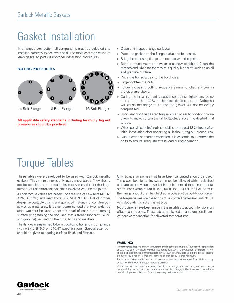
Garlock Metallic Gaskets
Leaders in Sealing Integrity
40
Torque TablesThese tables were developed to be used with Garlock metallic gaskets. They are to be used only as a general guide. They should not be considered to contain absolute values due to the large number of uncontrollable variables involved with bolted joints.
All bolt torque values are based upon the use of new nuts (ASTM A194, GR 2H) and new bolts (ASTM A193, GR B7) of proper design, acceptable quality and approved materials of construction as well as metallurgy. It is also recommended that two hardened steel washers be used under the head of each nut or turning surface (if tightening the bolt) and that a thread lubricant (i.e. oil and graphite) be used on the nuts, bolts and washers.
The flanges are assumed to be in good condition and in compliance with ASME B16.5 or B16.47 specifications. Special attention should be given to seating surface finish and flatness.
WARNING:Properties/applications shown throughout this brochure are typical. Your specific application should not be undertaken without independent study and evaluation for suitability. For specific application recommendations consult Garlock. Failure to select the proper sealing products could result in property damage and/or serious personal injury.
Performance data published in this brochure has been developed from field testing, customer field reports and/or in-house testing.
While the utmost care has been used in compiling this brochure, we assume no responsibility for errors. Specifications subject to change without notice. This edition cancels all previous issues. Subject to change without notice.
Only torque wrenches that have been calibrated should be used. The proper bolt tightening pattern must be followed with the desired ultimate torque value arrived at in a minimum of three incremental steps. For example: (30 ft. lbs., 60 ft. lbs., 100 ft. lbs.) All bolts in the flange should then be checked in consecutive bolt-to-bolt order.
The torque values are based on actual contact dimension, which will vary depending on the gasket type.
No provisions have been made in these tables to account for vibration effects on the bolts. These tables are based on ambient conditions, without compensation for elevated temperatures.
Gasket InstallationIn a flanged connection, all components must be selected and installed correctly to achieve a seal. The most common cause of leaky gasketed joints is improper installation procedures.
BOLTING PROCEDURES
1
2
34
1
2
34
5
6
7
8
1
2
34
5
6
7
8
9
10
11
12
13
14
15
16
4-Bolt Flange 8-Bolt Flange 16-Bolt Flange
» Clean and inspect flange surfaces.
» Place the gasket on the flange surface to be sealed.
» Bring the opposing flange into contact with the gasket.
» Bolts or studs must be new or in as-new condition. Clean the threads and lubricate them with a quality lubricant, such as an oil and graphite mixture.
» Place the bolts/studs into the bolt holes.
» Finger-tighten the nuts.
» Follow a crossing bolting sequence similar to what is shown in the diagrams above.
» During the initial tightening sequence, do not tighten any bolts/studs more than 30% of the final desired torque. Doing so will cause the flange to tip and the gasket will not be evenly compressed.
» Upon reaching the desired torque, do a circular bolt-to-bolt torque check to make certain that all bolts/studs are at the desited final torque.
» When possible, bolts/studs should be retorqued 12-24 hours after initial installation after observing all lockout / tag out procedures.
» Due to creep and stress relaxation, it is essential to prestress the bolts to ensure adequate stress load during operation.
All applicable safety standards including lockout / tag out procedures should be practiced.

Garlock Metalllic Gaskets
Leaders in Sealing Integrity
41
FLEXSEAL® EDGE® Kammprofile CMG* Jacketed Gasket
Nominal Pipe Size (inches)
Number of
Bolts
Size of
Bolts
Minimum Torque (ft.lbs)
Preferred Torque (ft.lbs)
Minimum Torque (ft.lbs)
Preferred Torque (ft.lbs)
Minimum Torque (ft.lbs)
Preferred Torque (ft.lbs)
Minimum Torque (ft.lbs)
Preferred Torque (ft.lbs)
Minimum Torque (ft.lbs)
Preferred Torque (ft.lbs)
0.50 4 0.50 16 47 9 52 8 42 11 37 18 53
0.75 4 0.50 22 60 12 60 11 54 16 60 25 60
1 4 0.50 30 60 15 60 13 60 21 60 27 60
1.25 4 0.50 33 60 16 60 24 60 33 60 42 60
1.5 4 0.50 47 60 23 60 31 60 43 60 59 60
2 4 0.63 74 120 36 120 55 120 87 120 94 120
2.5 4 0.63 87 120 43 120 63 120 101 120 108 120
3 4 0.63 120 120 63 120 102 120 120 120 120 120
4 8 0.63 92 120 47 120 76 120 105 120 111 120
5 8 0.75 124 200 63 200 106 200 146 200 189 200
6 8 0.75 178 200 89 200 137 200 185 200 173 200
8 8 0.75 200 200 128 200 190 200 250 200 200 200
10 12 0.88 236 320 120 320 178 320 235 320 300 320
12 12 0.88 320 320 163 320 178 320 312 320 320 320
14 12 1.00 408 490 209 490 268 490 396 490 451 490
16 16 1.00 421 490 210 490 267 490 377 490 449 490
18 16 1.13 649 710 328 710 381 710 560 710 562 710
20 20 1.13 572 710 289 710 335 710 494 710 562 710
24 20 1.25 820 1000 415 1000 438 1000 704 1000 740 1000
Torque Tables150# RAISED FACE FLANGES
Based on ASTM A193 B7 bolts - 60,000 psi maximum bolt stress
Based on ASTM A193 B7 bolts - 60,000 psi maximum bolt stress
FLEXSEAL® EDGE® Kammprofile CMG* Jacketed Gasket
Nominal Pipe Size (inches)
Number of
Bolts
Size of
Bolts
Minimum Torque (ft.lbs)
Preferred Torque (ft.lbs)
Minimum Torque (ft.lbs)
Preferred Torque (ft.lbs)
Minimum Torque (ft.lbs)
Preferred Torque (ft.lbs)
Minimum Torque (ft.lbs)
Preferred Torque (ft.lbs)
Minimum Torque (ft.lbs)
Preferred Torque (ft.lbs)
0.50 4 0.50 16 47 9 52 8 42 11 37 18 53
0.75 4 0.63 28 84 15 88 14 68 20 67 31 92
1 4 0.63 38 114 19 115 17 84 27 89 34 102
1.25 4 0.63 41 120 20 120 30 120 41 120 53 120
1.5 4 0.75 66 198 32 191 43 200 60 200 81 200
2 8 0.63 37 112 18 109 27 120 43 120 47 120
2.5 8 0.75 48 145 24 144 35 177 56 188 60 180
3 8 0.75 71 200 35 200 57 200 83 200 75 200
4 8 0.75 103 200 52 200 84 200 117 200 123 200
5 8 0.75 124 200 63 200 106 200 146 200 189 200
6 12 0.75 118 200 60 200 92 200 123 200 116 200
8 12 0.88 194 320 98 320 146 320 192 320 207 320
10 16 1.00 206 490 105 490 155 490 205 490 262 490
12 16 1.13 309 710 156 710 171 710 299 710 341 710
14 20 1.13 269 710 138 710 177 710 261 710 297 710
16 20 1.25 399 1000 203 1000 259 1000 365 1000 435 1000
18 24 1.25 478 1000 241 1000 280 1000 412 1000 414 1000
20 24 1.25 526 1000 266 1000 308 1000 454 1000 517 1000
24 24 1.50 723 1600 366 1600 386 1600 621 1600 652 1600
300# RAISED FACE FLANGES
*Includes GRAPHONIC®, G.E.T™ and TEPHONIC™
*Includes GRAPHONIC®, G.E.T™ and TEPHONIC™

Garlock Metallic Gaskets
Leaders in Sealing Integrity
42
Torque TablesFLEXSEAL® EDGE® Kammprofile CMG* Jacketed Gasket
Nominal Pipe Size (inches)
Number of
Bolts
Size of
Bolts
Minimum Torque (ft.lbs)
Preferred Torque (ft.lbs)
Minimum Torque (ft.lbs)
Preferred Torque (ft.lbs)
Minimum Torque (ft.lbs)
Preferred Torque (ft.lbs)
Minimum Torque (ft.lbs)
Preferred Torque (ft.lbs)
Minimum Torque (ft.lbs)
Preferred Torque (ft.lbs)
0.50 4 0.50 16 47 17 52 8 42
Contact Engineering
18 53
0.75 4 0.63 28 84 29 88 14 68 31 92
1 4 0.63 38 114 38 115 17 84 34 102
1.25 4 0.63 41 120 40 120 30 120 53 120
1.5 4 0.75 66 198 64 191 43 200 81 200
2 8 0.63 37 112 36 109 27 120 47 120
2.5 8 0.75 48 145 48 144 35 177 60 180
3 8 0.75 71 200 71 200 57 200 75 200
4 8 0.88 149 320 120 320 97 320 142 320
5 8 0.88 190 320 146 320 123 320 218 320
6 12 0.88 173 320 138 320 106 320 133 320
8 12 1.00 280 490 22- 490 170 490 241 490
10 16 1.13 314 710 230 691 170 710 287 710
12 16 1.25 456 1000 345 1000 188 941 376 1000
14 20 1.25 373 1000 304 911 195 975 328 983
16 20 1.38 532 1630 445 1335 283 1360 475 1360
18 24 1.38 567 1360 527 1360 306 1360 452 1357
20 24 1.50 604 1600 563 1600 326 1600 547 1600
24 24 1.75 962 2887 975 2924 513 2566 868 2603
Based on ASTM A193 B7 bolts - 60,000 psi maximum bolt stress
400# RAISED FACE FLANGES
FLEXSEAL® EDGE® Kammprofile CMG* Jacketed Gasket
Nominal Pipe Size (inches)
Number of
Bolts
Size of
Bolts
Minimum Torque (ft.lbs)
Preferred Torque (ft.lbs)
Minimum Torque (ft.lbs)
Preferred Torque (ft.lbs)
Minimum Torque (ft.lbs)
Preferred Torque (ft.lbs)
Minimum Torque (ft.lbs)
Preferred Torque (ft.lbs)
Minimum Torque (ft.lbs)
Preferred Torque (ft.lbs)
0.50 4 0.50 16 47 17 52 8 42
Contact Engineering
18 53
0.75 4 0.63 28 84 29 88 14 68 31 92
1 4 0.63 38 114 38 115 17 84 34 102
1.25 4 0.63 41 120 40 120 30 120 53 120
1.5 4 0.75 66 198 64 191 43 200 81 200
2 8 0.63 37 112 36 109 27 120 47 120
2.5 8 0.75 48 145 48 144 35 177 60 180
3 8 0.75 71 200 71 200 57 200 75 200
4 8 0.88 149 320 120 320 97 320 142 320
5 8 1.00 221 490 170 490 143 490 254 490
6 12 1.00 202 490 160 480 123 490 155 466
8 12 1.13 307 710 241 710 187 710 264 710
10 16 1.25 346 1000 254 763 188 938 317 951
12 20 1.25 365 1000 276 829 151 753 301 904
14 20 1.38 408 1224 332 996 213 1066 358 1075
16 20 1.50 514 1543 430 1291 274 1370 460 1379
18 20 1.63 757 2200 704 2112 409 2044 604 1811
20 24 1.63 695 2085 647 1941 375 1875 629 1886
24 24 1.88 1103 3308 1117 3350 588 2940 994 2983
Based on ASTM A193 B7 bolts - 60,000 psi maximum bolt stress
600# RAISED FACE FLANGES
*Includes GRAPHONIC®, G.E.T™ and TEPHONIC™
*Includes GRAPHONIC®, G.E.T™ and TEPHONIC™

Garlock Metalllic Gaskets
Leaders in Sealing Integrity
43
Torque TablesFLEXSEAL® EDGE® Kammprofile CMG* Jacketed Gasket
Nominal Pipe Size (inches)
Number of
Bolts
Size of
Bolts
Minimum Torque (ft.lbs)
Preferred Torque (ft.lbs)
Minimum Torque (ft.lbs)
Preferred Torque (ft.lbs)
Minimum Torque (ft.lbs)
Preferred Torque (ft.lbs)
Minimum Torque (ft.lbs)
Preferred Torque (ft.lbs)
Minimum Torque (ft.lbs)
Preferred Torque (ft.lbs)
0.50 4 0.75 22 100 24 100 12 100
Contact Engineering
24 73
0.75 4 0.75 31 100 33 100 15 100 34 103
1 4 0.88 49 160 49 160 22 160 44 131
1.25 4 0.88 53 160 52 160 39 193 68 204
1.5 4 1.00 89 266 85 256 58 289 109 328
2 8 0.88 48 160 47 160 35 176 60 180
2.5 8 1.00 65 245 65 245 47 245 81 242
3 8 0.88 106 319 81 244 66 328 87 260
4 8 1.13 191 572 153 458 124 622 182 545
5 8 1.25 268 804 206 617 173 865 307 921
6 12 1.13 221 664 176 527 135 675 170 511
8 12 1.38 333 1000 303 909 225 1127 319 956
10 16 1.38 306 919 278 835 205 1026 347 1040
12 20 1.38 368 1103 302 907 165 824 329 988
14 20 1.50 388 1164 321 963 206 1031 347 1040
16 20 1.63 514 1541 495 1485 315 1575 529 1586
18 20 1.88 991 2972 933 2800 542 2710 800 2401
20 20 2.00 934 2802 984 2952 540 2850 956 2867
24 20 2.50 1382 4400 1582 4747 833 4400 1409 4227
Based on ASTM A193 B7 bolts - 60,000 psi maximum bolt stress
900# RAISED FACE FLANGES
Based on ASTM A193 B7 bolts - 60,000 psi maximum bolt stress
FLEXSEAL® EDGE® Kammprofile CMG* Jacketed Gasket
Nominal Pipe Size (inches)
Number of
Bolts
Size of
Bolts
Minimum Torque (ft.lbs)
Preferred Torque (ft.lbs)
Minimum Torque (ft.lbs)
Preferred Torque (ft.lbs)
Minimum Torque (ft.lbs)
Preferred Torque (ft.lbs)
Minimum Torque (ft.lbs)
Preferred Torque (ft.lbs)
Minimum Torque (ft.lbs)
Preferred Torque (ft.lbs)
0.50 4 0.75 22 100 24 100 20 100
Contact Engineering
24 73
0.75 4 0.75 31 100 33 100 25 100 34 103
1 4 0.88 49 160 49 160 36 160 44 131
1.25 4 0.88 80 240 52 160 64 193 68 204
1.5 4 1.00 118 353 85 256 96 289 109 328
2 8 0.88 76 227 47 160 59 176 60 180
2.5 8 1.00 108 325 65 245 79 245 81 242
3 8 1.13 150 451 104 355 140 419 111 332
4 8 1.25 231 694 169 506 229 686 200 601
5 8 1.50 323 970 218 800 305 915 325 975
6 12 1.38 289 867 212 680 272 815 206 617
8 12 1.63 432 1297 337 1100 418 1253 354 1063
10 12 1.88 754 2262 547 2000 673 2018 682 2045
12 16 2.00 647 2200 532 2200 484 2200 580 1741
14 16 2.25 684 3180 655 3180 701 3180 707 2121
16 16 2.50 1141 4400 969 4400 1027 4400 1035 3104
18 16 2.75 1606 5920 1513 5920 1464 5920 1297 3892
20 16 3.00 1921 7720 1810 7720 1748 7720 1758 5273
24 16 3.50 3100 13000 2867 13000 2516 13000 2553 7658
1500# RAISED FACE FLANGES
*Includes GRAPHONIC®, G.E.T™ and TEPHONIC™
*Includes GRAPHONIC®, G.E.T™ and TEPHONIC™

Garlock Metallic Gaskets
Leaders in Sealing Integrity
44
Torque TablesFLEXSEAL® EDGE® Kammprofile CMG* Jacketed Gasket
Nominal Pipe Size (inches)
Number of
Bolts
Size of
Bolts
Minimum Torque (ft.lbs)
Preferred Torque (ft.lbs)
Minimum Torque (ft.lbs)
Preferred Torque (ft.lbs)
Minimum Torque (ft.lbs)
Preferred Torque (ft.lbs)
Minimum Torque (ft.lbs)
Preferred Torque (ft.lbs)
Minimum Torque (ft.lbs)
Preferred Torque (ft.lbs)
0.50 4 0.75 22 100 24 100 20 100
Contact Engineering
24 73
0.75 4 0.75 31 100 33 100 25 100 34 103
1 4 0.88 49 160 49 160 36 160 44 131
1.25 4 1.00 93 279 60 245 75 245 79 237
1.5 4 1.13 129 387 94 355 106 355 120 360
2 8 1.00 88 264 55 245 68 245 70 210
2.5 8 1.13 119 357 71 355 87 355 89 266
3 8 1.25 166 500 115 500 154 500 122 367
4 8 1.50 245 800 178 800 242 800 212 636
5 8 1.75 430 1500 289 1500 406 1500 432 1297
6 8 2.00 611 2200 448 2200 574 2200 434 1303
8 12 2.00 548 2200 427 2200 529 2200 449 1347
10 12 2.50 831 4400 646 4400 794 4400 805 2415
12 12 2.75 1326 5920 963 5920 875 5920 1050 3150
Based on ASTM A193 B7 bolts - 60,000 psi maximum bolt stress
2500# RAISED FACE FLANGES
WARNING:Properties/applications shown throughout this brochure are typical. Your specific application should not be undertaken without independent study and evaluation for suitability. For specific application recommendations consult Garlock. Failure to select the proper sealing products could result in property damage and/or serious personal injury.
Performance data published in this brochure has been developed from field testing, customer field reports and/or in-house testing.
While the utmost care has been used in compiling this brochure, we assume no responsibility for errors. Specifications subject to change without notice. This edition cancels all previous issues. Subject to change without notice.
*Includes GRAPHONIC®, G.E.T™ and TEPHONIC™
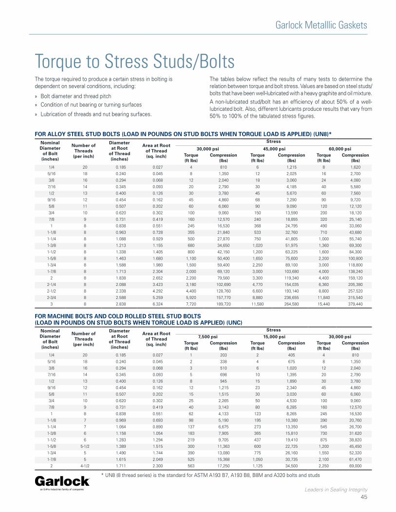
Garlock Metalllic Gaskets
Leaders in Sealing Integrity
45
Torque to Stress Studs/BoltsThe torque required to produce a certain stress in bolting is dependent on several conditions, including:
» Bolt diameter and thread pitch
» Condition of nut bearing or turning surfaces
» Lubrication of threads and nut bearing surfaces.
The tables below reflect the results of many tests to determine the relation between torque and bolt stress. Values are based on steel studs/bolts that have been well-lubricated with a heavy graphite and oil mixture.
A non-lubricated stud/bolt has an efficiency of about 50% of a well-lubricated bolt. Also, different lubricants produce results that vary from 50% to 100% of the tabulated stress figures.
Nominal Diameter
of Bolt (inches)
Number of Threads
(per inch)
Diameter at Root
of Thread(inches)
Area at Root of Thread(sq. inch)
Stress
30,000 psi 45,000 psi 60,000 psiTorque(ft lbs)
Compression (lbs)
Torque(ft lbs)
Compression (lbs)
Torque(ft lbs)
Compression (lbs)
1/4 20 0.185 0.027 4 810 6 1,215 8 1,620
5/16 18 0.240 0.045 8 1,350 12 2,025 16 2,700
3/8 16 0.294 0.068 12 2,040 18 3,060 24 4,080
7/16 14 0.345 0.093 20 2,790 30 4,185 40 5,580
1/2 13 0.400 0.126 30 3,780 45 5,670 60 7,560
9/16 12 0.454 0.162 45 4,860 68 7,290 90 9,720
5/8 11 0.507 0.202 60 6,060 90 9,090 120 12,120
3/4 10 0.620 0.302 100 9,060 150 13,590 200 18,120
7/8 9 0.731 0.419 160 12,570 240 18,855 320 25,140
1 8 0.838 0.551 245 16,530 368 24,795 490 33,060
1-1/8 8 0.963 0.728 355 21,840 533 32,760 710 43,680
1-1/4 8 1.088 0.929 500 27,870 750 41,805 1,000 55,740
1-3/8 8 1.213 1.155 680 34,650 1,020 51,975 1,360 69,300
1-1/2 8 1.338 1.405 800 42,150 1,200 63,225 1,600 84,300
1-5/8 8 1.463 1.680 1,100 50,400 1,650 75,600 2,200 100,800
1-3/4 8 1.588 1.980 1,500 59,400 2,250 89,100 3,000 118,800
1-7/8 8 1.713 2.304 2,000 69,120 3,000 103,680 4,000 138,240
2 8 1.838 2.652 2,200 79,560 3,300 119,340 4,400 159,120
2-1/4 8 2.088 3.423 3,180 102,690 4,770 154,035 6,360 205,380
2-1/2 8 2.338 4.292 4,400 128,760 6,600 193,140 8,800 257,520
2-3/4 8 2.588 5.259 5,920 157,770 8,880 236,655 11,840 315,540
3 8 2.838 6.324 7,720 189,720 11,580 264,580 15,440 379,440
FOR ALLOY STEEL STUD BOLTS (LOAD IN POUNDS ON STUD BOLTS WHEN TORQUE LOAD IS APPLIED) (UN8)*
Nominal Diameter
of Bolt (inches)
Number of Threads
(per inch)
Diameter at Root
of Thread(inches)
Area at Root of Thread(sq. inch)
Stress7,500 psi 15,000 psi 30,000 psi
Torque(ft lbs)
Compression (lbs)
Torque(ft lbs)
Compression (lbs)
Torque(ft lbs)
Compression (lbs)
1/4 20 0.185 0.027 1 203 2 405 4 810
5/16 18 0.240 0.045 2 338 4 675 8 1,350
3/8 16 0.294 0.068 3 510 6 1,020 12 2,040
7/16 14 0.345 0.093 5 698 10 1,395 20 2,790
1/2 13 0.400 0.126 8 945 15 1,890 30 3,780
9/16 12 0.454 0.162 12 1,215 23 2,340 45 4,860
5/8 11 0.507 0.202 15 1,515 30 3,030 60 6,060
3/4 10 0.620 0.302 25 2,265 50 4,530 100 9,060
7/8 9 0.731 0.419 40 3,143 80 6,285 160 12,570
1 8 0.838 0.551 62 4,133 123 8,265 245 16,530
1-1/8 7 0.969 0.693 98 5,190 195 10,380 390 20,760
1-1/4 7 1.064 0.890 137 6,675 273 13,350 545 26,700
1-3/8 6 1.158 1.054 183 7,905 365 15,810 730 31.620
1-1/2 6 1.283 1.294 219 9,705 437 19,410 875 38,820
1-5/8 5-1/2 1.389 1.515 300 11,363 600 22,725 1,200 45,450
1-3/4 5 1.490 1.744 390 13,080 775 26,160 1,550 52,320
1-7/8 5 1.615 2.049 525 15,368 1,050 30,735 2,100 61,470
2 4-1/2 1.711 2.300 563 17,250 1,125 34,500 2,250 69,000
FOR MACHINE BOLTS AND COLD ROLLED STEEL STUD BOLTS (LOAD IN POUNDS ON STUD BOLTS WHEN TORQUE LOAD IS APPLIED) (UNC)
* UN8 (8 thread series) is the standard for ASTM A193 B7, A193 B8, B8M and A320 bolts and studs

Garlock Metallic Gaskets
Leaders in Sealing Integrity
46
Troubleshooting Leaking JointsOne of the best methods for determining the cause of joint leakage is the careful examination of the gasket where the leakage occurred.
Observation Possible Remedies
Gasket badly corroded » Select replacement material with improved corrosion resistance
Gasket extruded excessively » Select replacement material with better cold flow properties » Select replacement material with better load capacity - i.e., more dense
Gasket grossly crushed » Select replacement material with better load carrying capacity » Provide means to prevent crushing the gasket by use of a stop ring or redesign of flanges
Gasket mechanically damaged due to overhang of raised face or flange bore
» Review gasket dimensions to insure gaskets are proper size » Make certain gaskets are properly centered in joint
No apparent gasket compression achieved
» Select softer gasket material » Select thicker gasket material » Reduce gasket area to allow higher unit seating load
Gasket substantially thinner on OD than ID due to excessive flange rotation or bending
» Alter gasket dimensions to move gasket reaction closer to bolts to minimize bending movement » Provide stiffness to flange by means of back-up rings » Select softer gasket material to lower required seating stresses » Reduce gasket area to lower seating stresses
Gasket unevenly compressed around circumference
» Make certain proper sequential bolt-up procedures are followed » Ensure flanges are properly aligned
Gasket thickness varies periodically around circumference
» Provide reinforcing rings for flanges to better distribute bolt load » Select gasket material with lower seating stress » Provide additional bolts if possible to obtain better load distribution » If flanges are warped, remachine or use softer gasket material

Garlock Metalllic Gaskets
Leaders in Sealing Integrity
47
Ordering GuideRW, RWI SPIRAL WOUND When ordering, specify:
» Nominal pipe size or gasket dimensions, and pressure class
» Winding and filler materials
» Centering and/or inner compression ring material
SW, SWI SPIRAL WOUNDWhen ordering, specify:
» OD and ID dimensions (and tolerance, if other than standard—see page 22)
» Thickness of gasket
» Winding and filler material
» Inner ring material, if required (Style SWI)
» Pressure rating
HH AND MCR MANHOLEWhen ordering, specify:
» Make and model of boiler and/or equipment if available (See chart page 11)
» Gasket style and configuration
» Dimensions of gasket (thickness, flange seating width, and shape)
» Maximum operating pressure and temperature
» Type of metal and filler materials
CUSTOM GASKETSA spiral wound gasket can be made to almost any dimension required. Possible designs include multiple windings and rings, with combinations of different fillers or special winding materials and ring shapes. Describe your application or send us a drawing and we’ll help you design the appropriate winding.
HEAT EXCHANGER The size restrictions for heat exchanger gaskets depend only on the available sizes of the materials. Heat exchanger gaskets are commonly made in diameters up to 120", with rib widths up to 1-1/4" and thicknesses up to 1/4".
When ordering, specify:
» Style number
» Shape (Give configuration code, page 21)
» Thickness
» Material (metal or metal and filler)
Plus specify (according to diagram below):
1. Outside diameter
2. Inside diameter
3. Rib width
4. Radii on ribs, at rib intersect points and around bolt holes
5. Bolt circle diameter
6. Distance from center line of gasket to center line of ribs
7. Size and number of bolt holes
8. Hole placement relative to center line of gasket
NOTE: In addition to the above information, drawings of your application are always helpful in proper dimensioning of gaskets.
WARNING:Properties/applications shown throughout this brochure are typical. Your specific application should not be undertaken without independent study and evaluation for suitability. For specific application recommendations consult Garlock. Failure to select the proper sealing products could result in property damage and/or serious personal injury.
Performance data published in this brochure has been developed from field testing, customer field reports and/or in-house testing.
While the utmost care has been used in compiling this brochure, we assume no responsibility for errors. Specifications subject to change without notice. This edition cancels all previous issues. Subject to change without notice.

Garlock Metallic Gaskets
Leaders in Sealing Integrity
48
Application Data FormDate:
For: Garlock Metallic Gasket Engineering
Email: [email protected]
Page: 1 of
Drawing attached Yes No
From:
Title:
Company:
Address:
Fax Number:
Phone Number:
Email Address:
APPLICATION
Pipe Flange
Heat Exchanger
Manway
Compressor
Pumps - centrifugal / horizontal split case
Flue Duct
Valve Bonnet
Other
SERVICE CONDITIONS
Maximum Temperature °F/°CInternal Pressure psig/bar
Thermal Cycling /24 hours
Continuous Operating Temperature °F/°CPSIG / bar Continuous Intermittent
Vibration Yes No
Other (specify)
BOLTS
Grade
Length
Diameter
Number
CHEMICAL COMPATIBILITY
Media
Concentration
pH
Liquid or Gas
FLANGE
Standard
Material
Size Rating
Surface Finish RMS
Phonographic Concentric
Face (raised, flat, tongue & groove, etc.)
Non-Standard
Material
I.D. / O.D.
Flange Thickness
Bolt Circle Diameter
Surface Finish RMS
Phonographic Concentric
Face (raised, flat, tongue & groove, etc.)
Comments:

Garlock Metalllic Gaskets
Leaders in Sealing Integrity
49
ConversionsCOMMON ABBREVIATIONS
SI - International Metric Standard
Pa - Pascal
psi - pounds per square inch
psig - pounds per square inch guage
oz - ounce
g - gram
lbf - pound force
kgf - kilogram force
N - Newton
in - inch
ft - foot
yd - yard
m - meter
gal - gallon
l - liter
PREFIXES
M (mega) = 1,000,000 = 106
k (kilo) = 1,000 = 103
c (centi) = 0.01 = 10-2
m (milli) = 0.001 = 10-3
u (micro) = 0.000001 = 10-6
Coversion from: To SI units: Multiply by:
Length
mil mm 0.0254in mm 25.4in cm 2.54ft m 0.3048yd m 0.9144
Weight
oz g 28.35oz kg 0.0283lb g 453.6lb kg 0.4536lb N 4.4482
Force
lbf N 4.448kgf N 9.8066
Area
in2 cm2 6.4516ft2 m2 0.0929
Pressure
bar psi 14.5psi Pa 6895psi kPa 6.89psi bar 0.069psi MPa 0.0069
N/m2 Pa 1.00N/mm2 MPa 1.00
Torque
in-lb Nm 0.113ft/lb Nm 1.3558
Density
oz/in3 g/cm3 1.73g/cm3 kg/m3 1000lb/ft3 kg/m3 16.02lb/ft3 g/cm3 0.01602
Adhesion
lb/in kN.m 0.1751
Volume
gal I 3.7854gal m3 0.0038
METRIC CONVERSIONS

Tel: 1-877-GARLOCK / 315.597.4811 Fax: 800.543.0598 / 315.597.3216www.garlock.com
GARLOCKan EnPro Industries family of companies
GarlockGPTGarlock AustraliaGarlock de Canada, LTD
Garlock ChinaGarlock SingaporeGarlock GermanyGarlock India Private Limited
Garlock de Mexico, S.A. De C.V.Garlock New ZealandGarlock Great Britain LimitedGarlock Middle East
GMG 1-1_01.2019


![Garlock Metallic Gasket Catalog[1]](https://img.pdfslide.net/doc/110x75/577cc5771a28aba7119c7b57/garlock-metallic-gasket-catalog1.jpg)