Embed Size (px)
Citation preview

Gas Carriers: Arrangements & Characteristics
Rich DelpizzoManager, Global Gas Solutions
Las Vegas, NVJuly 2014
Presentation to Marine Chemists

2
Overview
� LNG carriers
� History
� Fleet size and ship size
� Regulatory framework
� Cargo containment

3
About ABS
� Founded in 1862
� Not-for-profit marine classification society
� 3,500+ employees
� 200 offices, 70 countries
� ISO 9000 and 14000 certified
� OSHAS 18001 certified
� More than 200 Rules and Guides
� More than 12,200 ships in class totaling over 212 mGT
� More than 2,600 new construction ships under survey

4
What is Classification?
� Classification societies establish and apply technical standards in relation to the design, construction and survey of marine related facilities including ships and offshore structures
� Classification addresses the life cycle of a ship or offshore unit from design to decommissioning

5
� More than 50 organizations offer some form of classification service
� 12 societies form the membership of IACS – class in excess of 90% of the world’s tonnage
How Many Class Societies?

6
IACS Members

7
ABS Experience
� Gas carrier experience
� First to offer classification services to gas industry
� More than 50 years experience
� Contributed to the development of the IMO Gas Code
� First classification society invited to join the Society of International
Gas Tanker and Terminal Operators (SIGTTO)
� Over 80 LNG carriers classed

8
LNG Carriers: History
9
A Short History of Marine LNG Transportation
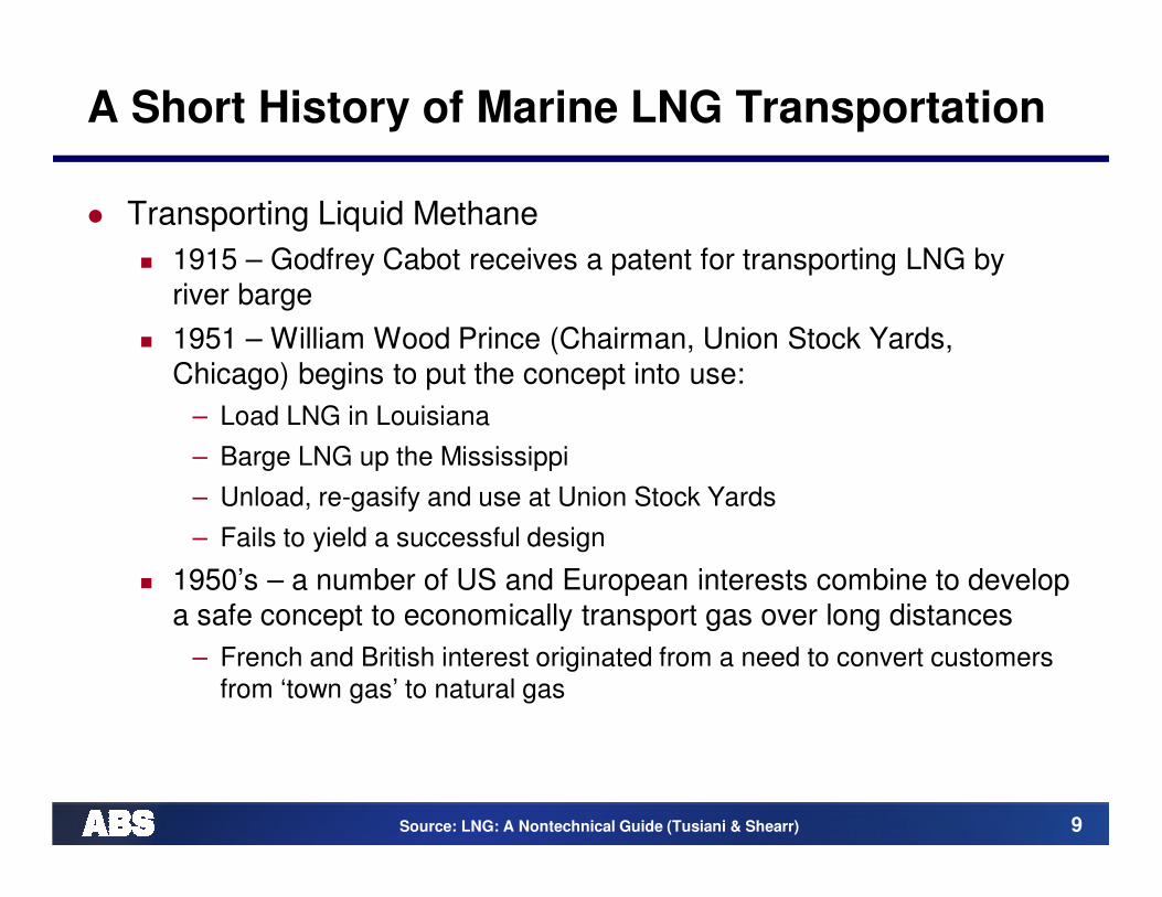
� Transporting Liquid Methane
� 1915 – Godfrey Cabot receives a patent for transporting LNG by
river barge
� 1951 – William Wood Prince (Chairman, Union Stock Yards,
Chicago) begins to put the concept into use:
– Load LNG in Louisiana
– Barge LNG up the Mississippi
– Unload, re-gasify and use at Union Stock Yards
– Fails to yield a successful design
� 1950’s – a number of US and European interests combine to develop
a safe concept to economically transport gas over long distances
– French and British interest originated from a need to convert customers
from ‘town gas’ to natural gas
Source: LNG: A Nontechnical Guide (Tusiani & Shearr)
10
A Short History of Marine LNG Transportation
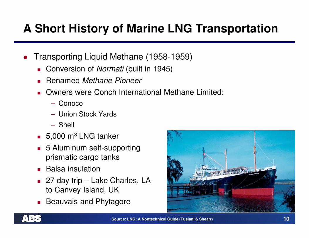
� Transporting Liquid Methane (1958-1959)
� Conversion of Normati (built in 1945)
� Renamed Methane Pioneer
� Owners were Conch International Methane Limited:
– Conoco
– Union Stock Yards
– Shell
� 5,000 m3 LNG tanker
� 5 Aluminum self-supporting
prismatic cargo tanks
� Balsa insulation
� 27 day trip – Lake Charles, LA
to Canvey Island, UK
� Beauvais and Phytagore
Source: LNG: A Nontechnical Guide (Tusiani & Shearr)

11
A Short History of Marine LNG Transportation
� 1965 – Purpose Built Ships
� Methane Princess and Methane Progress
– Conch International
– 9 prismatic cargo tanks
– 27,400 m3 capacity per tanker
Source: LNG: A Nontechnical Guide (Tusiani & Shearr)

12
A Short History of Marine LNG Transportation
� 1965 – Jules Verne
� Société Gaz-Marine
� Cylindrical cargo containment
� 25,840 m3 tanker
� 1971 – Descartes
� Gazocean
� Membrane tank concept
� 50,000 m3 tanker
Source: LNG: A Nontechnical Guide (Tusiani & Shearr)

13
LNG Construction
Source: LNG: A Nontechnical Guide (Tusiani & Shearr)
14
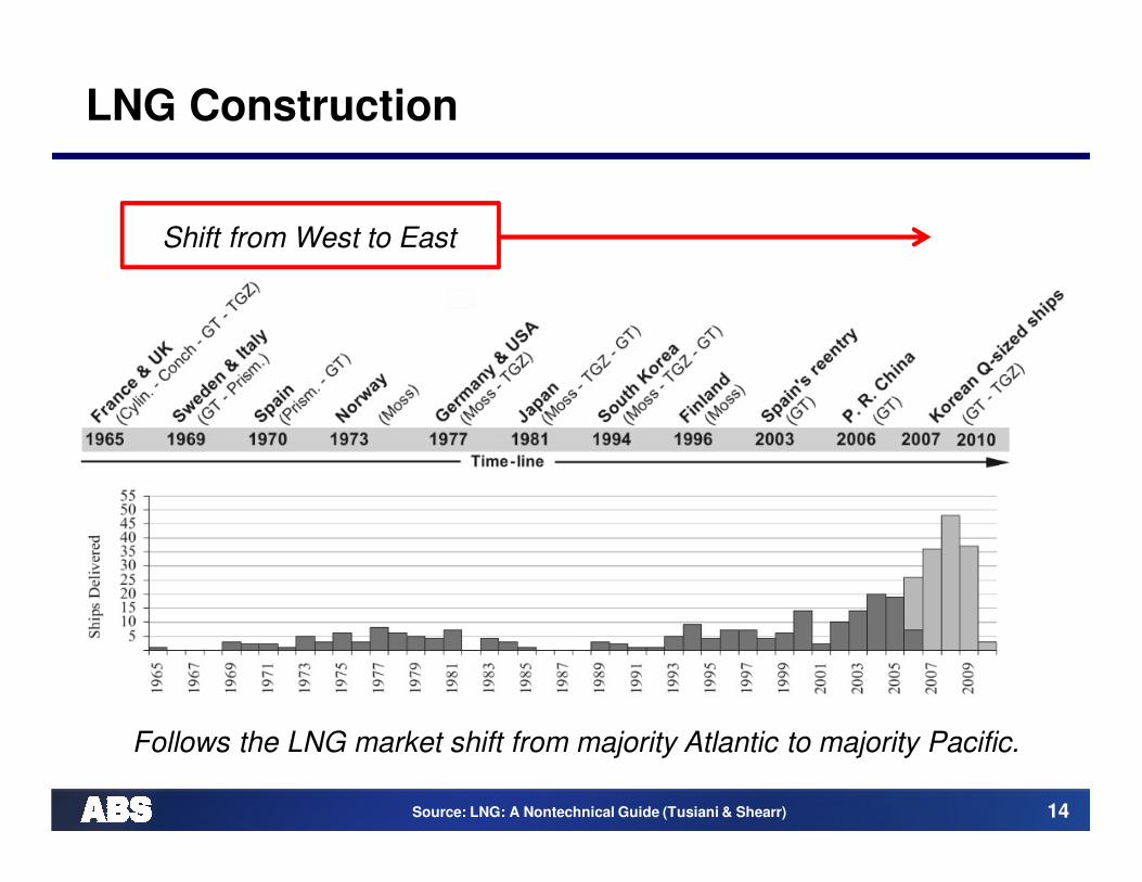
Shift from West to East
Follows the LNG market shift from majority Atlantic to majority Pacific.
LNG Construction
Source: LNG: A Nontechnical Guide (Tusiani & Shearr)
15
Ship Sizes
16
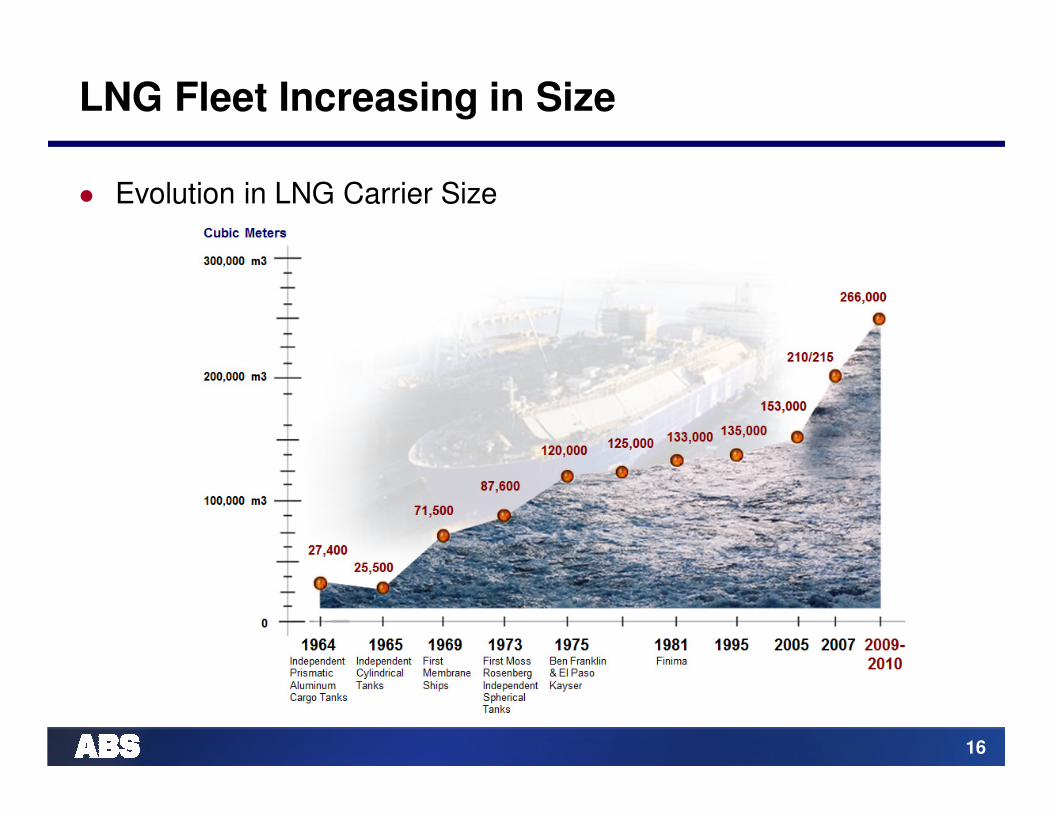
LNG Fleet Increasing in Size
� Evolution in LNG Carrier Size

17
LNG Fleet & Orderbook by Size
195 11 3
74
188
27 3114
9
64
0
20
40
60
80
100
120
140
160
180
200
Nu
mb
er
of
Sh
ips
Cargo Capacity x 1000 m3
Orderbook
Existing fleet

18
LNG Carrier Fleet Age Profile
Existing Fleet...Current Orderbook...Projected New Business
42 Ships Age 31+
LNG Carrier Fleet Profile - No. Ships1 Jan 2011 Existing Fleet - Projected Current Orderbook - Projected New Business
By Date of Build
Spring 2012 Outlook - Base Case
0
2
4
6
8
10
12
14
16
18
20
22
24
26
28
30
32
34
36
38
40
42
44
46
48
50
52
54
56
1982 1984 1986 1988 1990 1992 1994 1996 1998 2000 2002 2004 2006 2008 2010 2012 2014 2016 2018
Projected New Business
Current Orderbook
Exist Fleet

19
LNG Carrier Fleet Age Profile
Existing Fleet...Current Orderbook...Projected New Business
42 Ships Age 31+
LNG Carrier Fleet Profile - No. Ships1 Jan 2011 Existing Fleet - Projected Current Orderbook - Projected New Business
By Date of Build
Spring 2012 Outlook - Base Case
0
2
4
6
8
10
12
14
16
18
20
22
24
26
28
30
32
34
36
38
40
42
44
46
48
50
52
54
56
1982 1984 1986 1988 1990 1992 1994 1996 1998 2000 2002 2004 2006 2008 2010 2012 2014 2016 2018
Projected New Business
Current Orderbook
Exist Fleet WAS about
200 ships by
2006IS over
380 today
Source: Clarksons.com

20
Regulatory Framework for LNG Carriers

21
Regulatory Framework: Safety
� IMO
� International Code for the Construction
and Equipment of Ships Carrying
Liquefied Gases in Bulk (IGC Code)
� Revised IGC Code
� International Convention for the Safety
of Life at Sea, 1974 (SOLAS)
� International Convention on Standards
of Training, Certification and Watch-
keeping for Seafarers, 1978 (STCW)
(Amended 1995)

22
Class Requirements
� ABS Steel Vessel Rules
� Part 5C, Chapter 8
� ABS Guides
� ABS Guide for Dual Fuel Engines
� ABS Guide for Propulsion Systems for
LNG Carriers
� ABS Guide for Gas Fueled Ships
� IACS

23
Regulatory Framework: Safety
� Additional requirements may be imposed by flag Administrations
� Regulations of each harbor and terminal
� US Regulations, 46 CFR
� Other National Regulations, such as Regulations on Transportation
and Storage of Hazardous Substances by Ships (Japan)

24
USCG Requirements: LNG Carriers in US Ports
� Title 46 of the United States Code of Federal Regulations (or ’46 CFR’) Part 154 – “Safety Standards for Self-Propelled Vessels Carrying Bulk Liquefied Gases”
� Certificate of Compliance
� Foreign flag vessels must obtain a Certificate of Compliance from
the US Coast Guard (as opposed to a “Certificate of Inspection”,
which is issued to US flag vessels)
� Guidance for applying for this Certificate is found in 46 CFR 154.22

25
Chemical Transportation Industry Advisory Committee
� CTAC was established to provide direct industry input to the USCG on dealing with chemical and gas carrier issues
� ABS one of 8 original members
� CTAC helped form US position on the development of the original Gas Code (1973-1975)
� Still an important voice in the US LNG industry
26
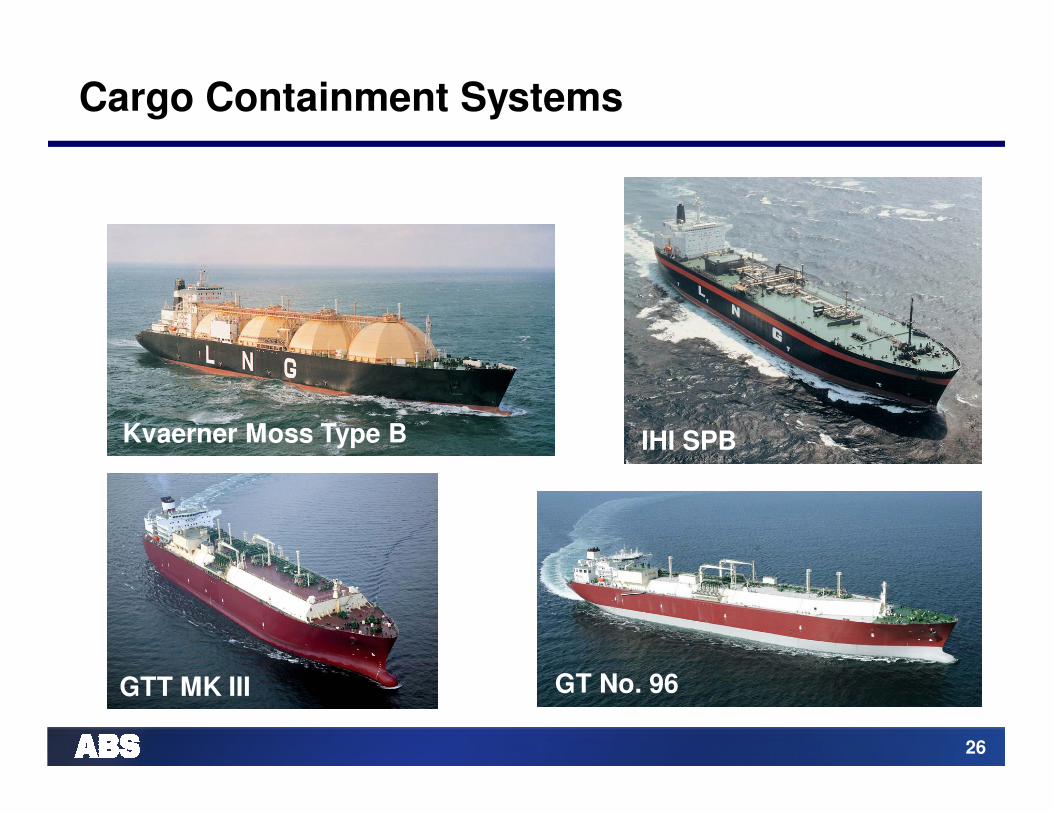
Cargo Containment Systems
GT No. 96
IHI SPBKvaerner Moss Type B
GTT MK III

27
Cargo Containment Systems
� A cargo containment system is the total arrangement for containing cargo including, where fitted:
� A primary barrier (the cargo tank)
� Secondary barrier (if fitted)
� Associated thermal insulation
� Any intervening spaces; and
� Adjacent structure, if necessary, for the support of these elements
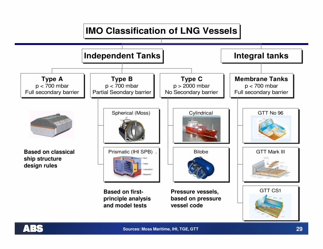
� The basic cargo tank types utilized on board gas carriers are Independent and Integral
Sources: www.liquefiedgascarrier.com, IGC Code

28
Independent Tanks
� Independent tanks are completely self-supporting and do not form part of the ship’s hull structure
� They do not contribute to the hull strength of a ship
� IGC Code Chapter 4 (para. 4.2.4) defines three different types of independent tanks for gas carriers:
� Type A
� Type B
� Type C
Sources: www.liquefiedgascarrier.com, IGC Code
29
Type Ap < 700 mbar
Full secondary barrier
Spherical (Moss)
Prismatic (IHI SPB) .
Type Bp < 700 mbar
Partial Seondary barrier
Cylindrical
Bilobe
Type Cp > 2000 mbar
No Secondary barrier
Independent Tanks
GTT No 96
GTT Mark III
GTT CS1
Membrane Tanksp < 700 mbar
Full secondary barrier
Integral tanks
IMO Classification of LNG Vessels
Sources: Moss Maritime, IHI, TGE, GTT
Based on classical
ship structure
design rules
Based on first-
principle analysis
and model tests
Pressure vessels,
based on pressure
vessel code

30
Type A Tanks
� Constructed primarily of flat surfaces
� Independent self-supporting prismatic tank which requires conventional internal stiffening
� Maximum allowable tank design pressure in the vapor space for this type of system is 0.7 barg – operate near atmospheric pressure
� Tank is externally insulated with foam
� Requires secondary barrier – hold space may act as secondary barrier if constructed of steels capable of withstanding low temperatures
� Found on LPG carriers

31
Type A Tanks
� The IGC Code stipulates that a secondary barrier must be able to contain tank leakage for a period of 15 days (IGC 4.7.4)
� The secondary barrier must be a complete barrier capable of
containing the whole tank volume at a defined angle of heel and may
form part of the ship’s hull
� Appropriate parts of the ship’s hull are constructed of special steel
capable of withstanding low temperatures. The alternative is to build
a separate secondary barrier around each cargo tank.
� The hold spaces must be filled with inert gas to prevent a flammable atmosphere being created in the event of primary barrier leakage (IGC 9.2)

32
Type A Tanks
Based on classical
ship structure
design rules

33
Type B Tanks
� Constructed of flat surfaces or they may be of the spherical type
� Maximum allowable tank design pressure in the vapor space for this type of
system is 0.7 barg – operate near atmospheric pressure
� Found on LNG carriers
� Tank is externally insulated with foam
� Cargo hold spaces contain dry air but may be inerted

34
Type B Tanks
� Because of the enhanced design factors, a Type ‘B’ tank requires only a partial secondary barrier in the form of a drip tray
� This type of containment system is the subject of much more detailed stress analysis compared to Type ‘A’ systems, and include an investigation of fatigue life and a crack propagation analysis
� The most common arrangement of Type ‘B’ tank is a spherical tank, known as the Moss Rosenberg, Kvaerner Moss or simply Moss design
� There are Type ‘B’ tanks of prismatic shape in LNG service. The prismatic Type ‘B’ tank has the benefit of maximizing ship and deck space.

35
Type B: Spherical Tanks – MOSS
� Historically spherical tanks are dominant as first choice of Japanese shipyards

36
Type B: Spherical Tanks – MOSS
� General layout of ship
Source: Mitsui O.S.K. Lines

37
Type B: Spherical Tanks – “SAYAENDO”
� MHI design that features a continuous cover integrated with the ship's hull
� Builds on the strength of spherical tank LNG carriers (reliability)
� Lightweight construction
� Suitable for cold regions

38
Advantages of Moss Tanks
� The spaces between the inner hull and outer hull are used for ballast and provide protection to the tanks in the event of collision or grounding
� No secondary barrier, primarily due to their spherical construction – high degree of safety against fracture or failure
� ‘Leak before Failure’ concept – presumes that the primary barrier will fail progressively, not suddenly and catastrophically
� In the case of a crack occurring in the tank material, a small leakage
of LNG within the insulation detected by gas detection
� The drip pan, installed directly below each cargo tank, is fitted with
temperature sensors to detect the presence of LNG
39
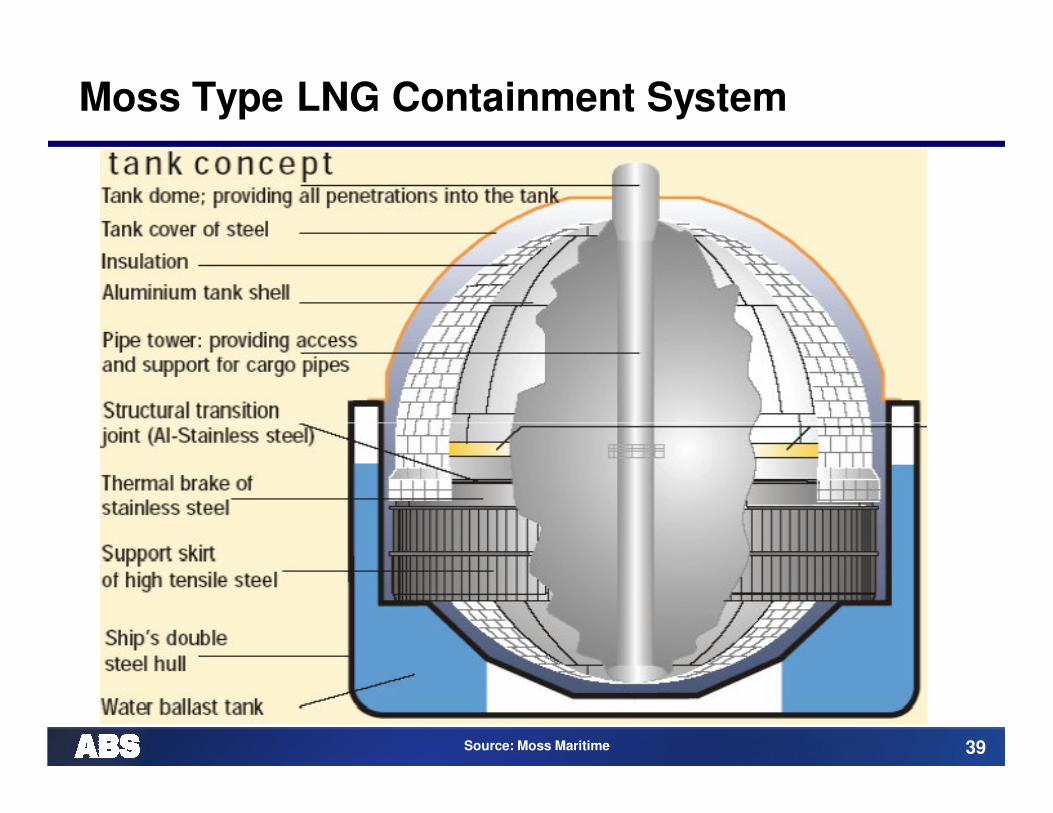
Moss Type LNG Containment System
Source: Moss Maritime

40
Moss Type LNG Containment System
Gas Detection at equatorial ring area and at the drip pan.
Source: Moss Maritime

41
Moss Type LNG Containment System
Source: Moss Maritime

42
Type B: Prismatic Tanks – IHI SPB
� Self-supporting, Prismatic, Independent Type B tank (IHI SPB)
� Strong and robust system, but expensive
� So far only 2 ships built(ABS class)
� Cargo tank material
� Aluminium
� Stainless steel
� 9% Ni Steel

43
Type B: Prismatic Tanks – IHI SPB
� Advantages:
� Eliminates sloshing loads, so can be used partially filled
� Advantageous for ‘cargoes of opportunity’
� Relatively flat surface, allowing processing gear for Floating LNG
facilities
� Can be tailor built to fit a hull

44
IHI SPB System (Self-Supporting Prismatic Type B)

45
IHI SPB System

46
Type C Tanks: “Cryogenic Pressure Vessels”
� Normally spherical or cylindrical pressure vessels having design pressures
higher than 2 barg
� Designed and built to conventional pressure vessel codes
� No secondary barrier is required and the hold space can be filled with either inert
gas or dry air
� Technology of choice for the small LNG or LPG carriers
� Dominant design for LNG fueled ships
47
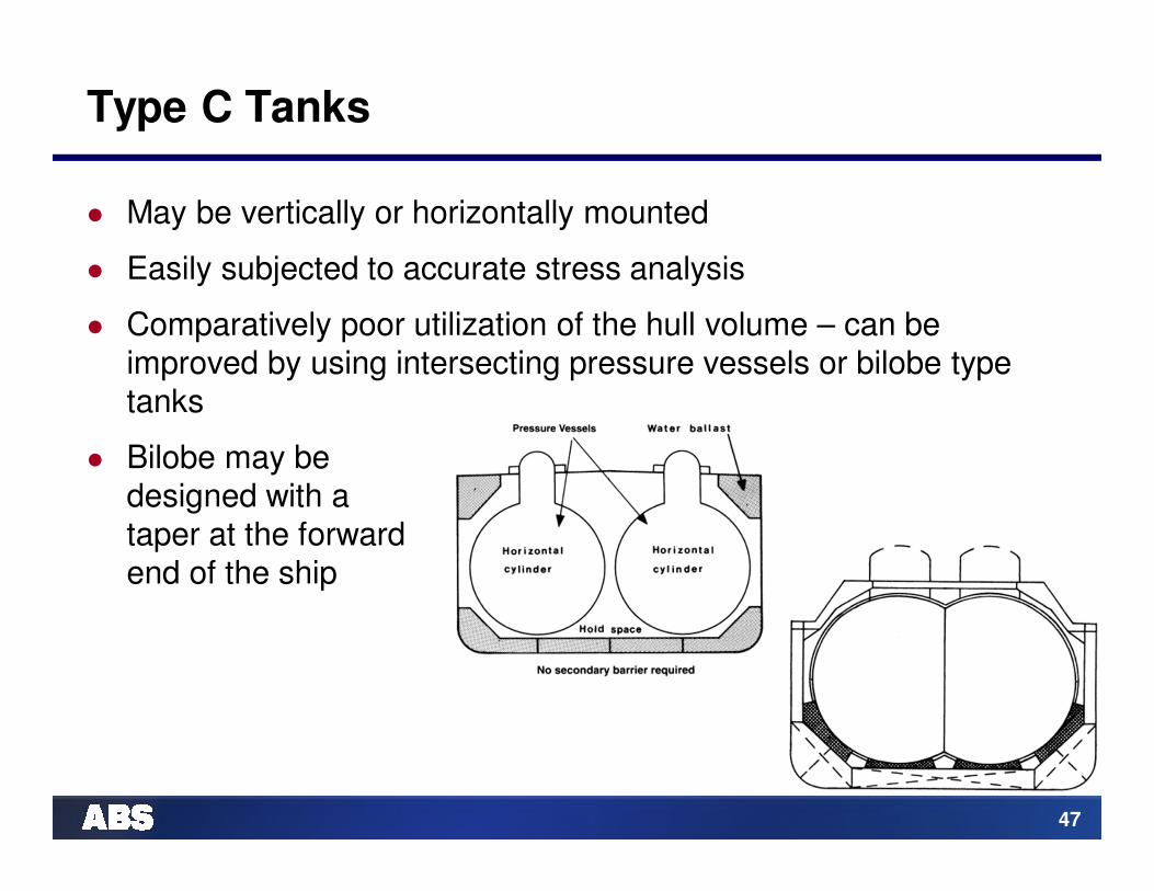
Type C Tanks
� May be vertically or horizontally mounted
� Easily subjected to accurate stress analysis
� Comparatively poor utilization of the hull volume – can be improved by using intersecting pressure vessels or bilobe type tanks
� Bilobe may be designed with a taper at the forward end of the ship
48
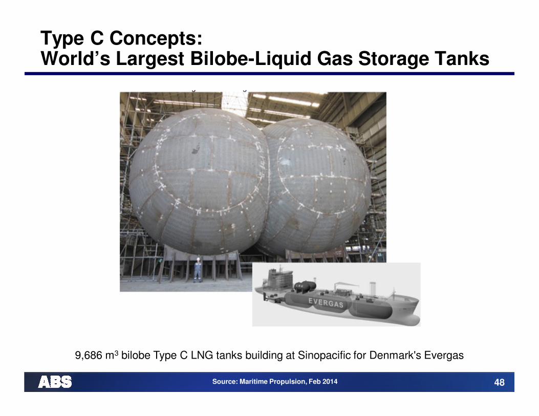
Type C Concepts: World’s Largest Bilobe-Liquid Gas Storage Tanks
9,686 m3 bilobe Type C LNG tanks building at Sinopacifi c for Denmark's Evergas
Source: Maritime Propulsion, Feb 2014

49
Independent Tanks: Type C – Bilobe
� Bilobe tanks being considered for 20-30,000 m3 size ships
Source: TGE Marine Gas Engineering
50
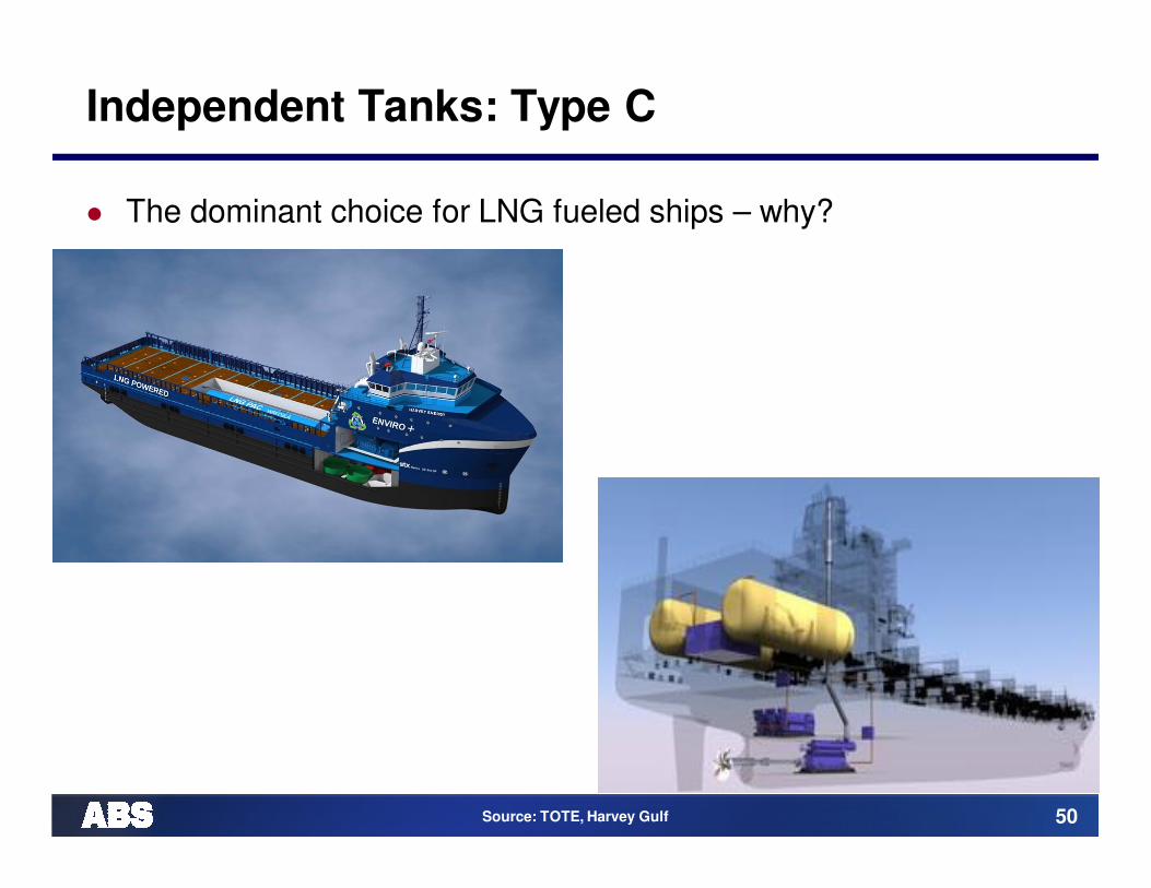
Independent Tanks: Type C
� The dominant choice for LNG fueled ships – why?
Source: TOTE, Harvey Gulf

51
Membrane Tanks
� Very thin primary barrier (membrane – 0.7 to 1.5 mm thick) which is supported through the insulation (IGC 4.2.2 allows up to 10 mm)
� Tanks are not self-supporting like independent tanks - inner hull forms the load bearing structure
� Membrane containment systems must always be provided with a secondary barrier to ensure the integrity of the total system in the event of primary barrier leakage
� Thermal expansion or contraction is compensated without over-stressing the membrane itself

52
Membrane Tanks: Principle
Hull Structure
Secondary insulation
Secondary membrane
Primary insulation
Primary membrane

53
Membrane Tanks: Principle

54
Membrane Tank: GTT No. 96
Source: GTT
Insulation:Plywood boxesfilled with perlite or fiberglass
Membranes - Invar (36% Ni)

55
Membrane Tank: GT No. 96
Source: GTT

56
Membrane Tanks: GTT Mark III
Insulation:Reinforced Polyurethane
Primary Membrane:Corrugated SUS 304
Secondary Membrane:Glued “triplex”
Source: GTT

57
Other Membrane Tank Designs
GTT CS-1
GTT Mark V
Source: GTT

58
Lower Boil-off Rate: GTT Membrane Systems
� MARK III Flex
� Increased insulation
thickness from 270 up
to 400 mm BOR < 0.1 %
� No.96 Evolution
� Using other insulation
materials such as glass wool:
No. 96 GW
� Modifications of the insulation
layers or boxes (including
PUR foam)
� BOR about 0.1 %
Source: GTT

59
New Cargo Containment Systems being Developed
Primary Membrane
Inter-barrier Board
Secondary Membrane
Membrane Anchor
Insulation Panel
Corner Insulation
Thick Corner PlateCorner Membrane
Corner Anchor
Source KOGAS
Source Tradewinds/WAVEspec
Samsung SCA-W/S Membrane System
Source Hyundai H.I.
Source Samsung H.I.
KOGAS KC-1 Membrane System
Hyundai Membrane System WAVEspec FPS (NASSCO)

60
Advantages of Membrane Tanks
� Generally smaller gross tonnage
� Maximum use of hold’s volume for cargo
� Unrestricted navigation visibility
� Lower wheelhouse and cargo control room air drafts

61
Trends for Containment System Status November 2013
14
7
13
2537
15
10
Orderbook by Containment system
No. 96
No. 96 GW
No. 96 L03
Mark III
Mark III FLEX
MOSS
Type C
5 8
3
116
24
110
5
3
113
14
2
Fleet by Containment system
No. 82
No. 85
No. 88
No. 96
No. 96 GW
Mark I
Mark III
Mark III FLEX
CS1
MOSS
Type C
SPB

62
LNG Bunkering

63
LNG Bunkering: Shore, Ships & Barges
� Infrastructure availability to support LNG as a Marine Fuel
� From Shore
� Dedicated facility
� Truck on jetty
� Containerized fuel
� From Sea
� LNG bunker barge or vessel
� Mooring dolphin
� Ship-to-ship
� Bunkering procedures
� Crew training requirements
� Risks, hazards and safeguards
Courtesy: Jensen Maritime Consultants

64
GTT Bunker Barge
Source: Marine Link

65
Argent Marine Bunker Barge
Courtesy: Argent Marine

www.eagle.org


![€¦ · [IET Wiring Regulations 17th Edition] Supply characteristics and earthing arrangements TN-C-S Earthing Arrangements TN-S d.c. Number & type of live conductors a.c. Please](https://img.pdfslide.net/doc/110x75/5ee0b01bad6a402d666bd4fe/iet-wiring-regulations-17th-edition-supply-characteristics-and-earthing-arrangements.jpg)


![EICR 25 Queens Terrace 2015 - Jesmond Student Properties€¦ · NAPIT [IF-T Wiring Regulations 17th Edition] Supply characteristics and earthing arrangements Earthing Arrangements](https://img.pdfslide.net/doc/110x75/5ee0b014ad6a402d666bd4fa/eicr-25-queens-terrace-2015-jesmond-student-properties-napit-if-t-wiring-regulations.jpg)