Embed Size (px)
Citation preview

Installation and Service Instructions
Read carefully before carrying out installation and maintenance.
Gas central heating boilers
Logano G234X
6 7
20 8
06 0
28-0
0.1
T
CAUTION!Before commissioning the boiler, heed the safety instructions for installation and maintenance.
DANGER!If installation, adjustment, modification, operation or maintenance of the heating system is carried out by an unqualified person, this may result in a fatal injury or property damage. Follow the instructions in this installation and maintenance manual exactly. If you require assistance or further information, contact a qualified contractor, an suitable service provider or the gas supply company.
DANGER!These instructions are part of the technical documents that must be handed over to the owner/operator of the heating system. Discuss the content of this manual with the owner/operator of the heating system to ensure that they are familiar with all information required for operation of the heating system.
Gas central heating boilers
6 72
0 81
1 23
3 (2
017/
02) U
S
Content
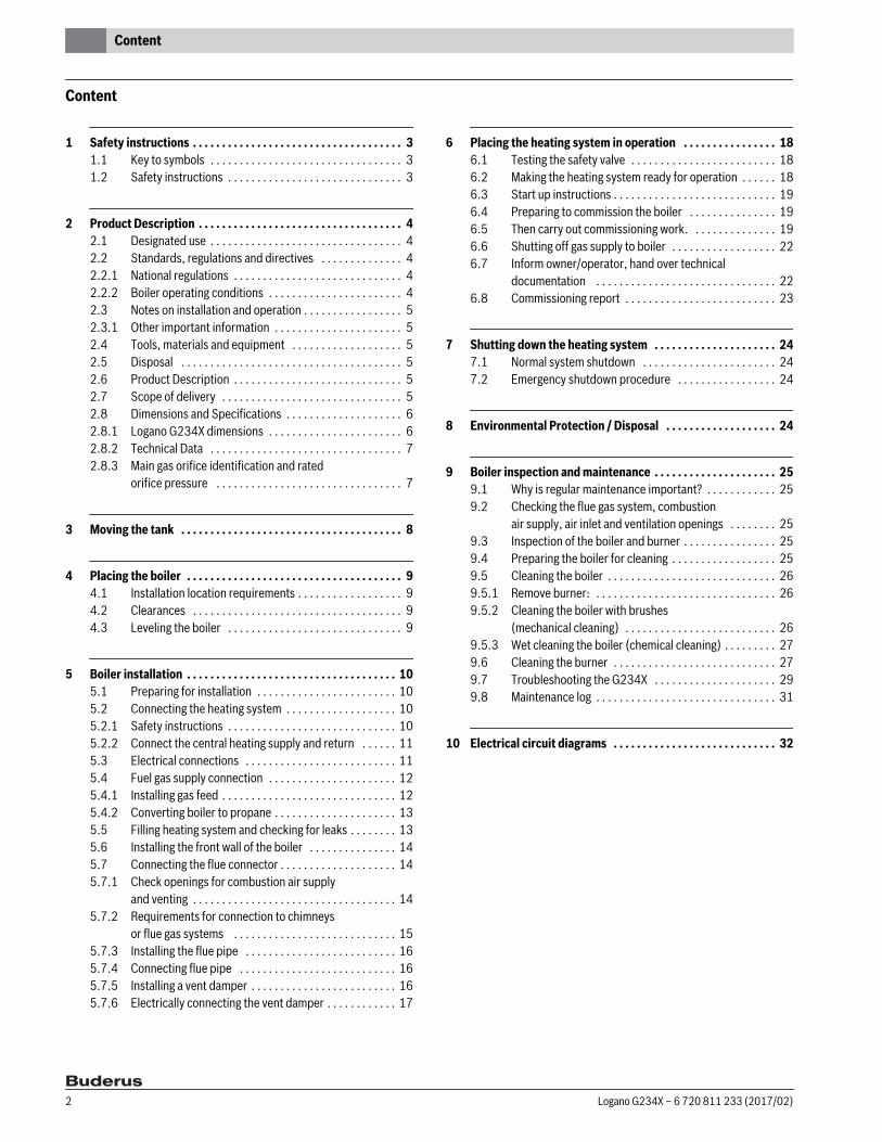
Content
1 Safety instructions . . . . . . . . . . . . . . . . . . . . . . . . . . . . . . . . . . . . 31.1 Key to symbols . . . . . . . . . . . . . . . . . . . . . . . . . . . . . . . . . 31.2 Safety instructions . . . . . . . . . . . . . . . . . . . . . . . . . . . . . . 3
2 Product Description . . . . . . . . . . . . . . . . . . . . . . . . . . . . . . . . . . . 42.1 Designated use . . . . . . . . . . . . . . . . . . . . . . . . . . . . . . . . . 42.2 Standards, regulations and directives . . . . . . . . . . . . . . 42.2.1 National regulations . . . . . . . . . . . . . . . . . . . . . . . . . . . . . 42.2.2 Boiler operating conditions . . . . . . . . . . . . . . . . . . . . . . . 42.3 Notes on installation and operation . . . . . . . . . . . . . . . . . 52.3.1 Other important information . . . . . . . . . . . . . . . . . . . . . . 52.4 Tools, materials and equipment . . . . . . . . . . . . . . . . . . . 52.5 Disposal . . . . . . . . . . . . . . . . . . . . . . . . . . . . . . . . . . . . . . 52.6 Product Description . . . . . . . . . . . . . . . . . . . . . . . . . . . . . 52.7 Scope of delivery . . . . . . . . . . . . . . . . . . . . . . . . . . . . . . . 52.8 Dimensions and Specifications . . . . . . . . . . . . . . . . . . . . 62.8.1 Logano G234X dimensions . . . . . . . . . . . . . . . . . . . . . . . 62.8.2 Technical Data . . . . . . . . . . . . . . . . . . . . . . . . . . . . . . . . . 72.8.3 Main gas orifice identification and rated
orifice pressure . . . . . . . . . . . . . . . . . . . . . . . . . . . . . . . . 7
3 Moving the tank . . . . . . . . . . . . . . . . . . . . . . . . . . . . . . . . . . . . . . 8
4 Placing the boiler . . . . . . . . . . . . . . . . . . . . . . . . . . . . . . . . . . . . . 94.1 Installation location requirements . . . . . . . . . . . . . . . . . . 94.2 Clearances . . . . . . . . . . . . . . . . . . . . . . . . . . . . . . . . . . . . 94.3 Leveling the boiler . . . . . . . . . . . . . . . . . . . . . . . . . . . . . . 9
5 Boiler installation . . . . . . . . . . . . . . . . . . . . . . . . . . . . . . . . . . . . 105.1 Preparing for installation . . . . . . . . . . . . . . . . . . . . . . . . 105.2 Connecting the heating system . . . . . . . . . . . . . . . . . . . 105.2.1 Safety instructions . . . . . . . . . . . . . . . . . . . . . . . . . . . . . 105.2.2 Connect the central heating supply and return . . . . . . 115.3 Electrical connections . . . . . . . . . . . . . . . . . . . . . . . . . . 115.4 Fuel gas supply connection . . . . . . . . . . . . . . . . . . . . . . 125.4.1 Installing gas feed . . . . . . . . . . . . . . . . . . . . . . . . . . . . . . 125.4.2 Converting boiler to propane . . . . . . . . . . . . . . . . . . . . . 135.5 Filling heating system and checking for leaks . . . . . . . . 135.6 Installing the front wall of the boiler . . . . . . . . . . . . . . . 145.7 Connecting the flue connector . . . . . . . . . . . . . . . . . . . . 145.7.1 Check openings for combustion air supply
and venting . . . . . . . . . . . . . . . . . . . . . . . . . . . . . . . . . . . 145.7.2 Requirements for connection to chimneys
or flue gas systems . . . . . . . . . . . . . . . . . . . . . . . . . . . . 155.7.3 Installing the flue pipe . . . . . . . . . . . . . . . . . . . . . . . . . . 165.7.4 Connecting flue pipe . . . . . . . . . . . . . . . . . . . . . . . . . . . 165.7.5 Installing a vent damper . . . . . . . . . . . . . . . . . . . . . . . . . 165.7.6 Electrically connecting the vent damper . . . . . . . . . . . . 17
6 Placing the heating system in operation . . . . . . . . . . . . . . . . 186.1 Testing the safety valve . . . . . . . . . . . . . . . . . . . . . . . . . 186.2 Making the heating system ready for operation . . . . . . 186.3 Start up instructions . . . . . . . . . . . . . . . . . . . . . . . . . . . . 196.4 Preparing to commission the boiler . . . . . . . . . . . . . . . 196.5 Then carry out commissioning work. . . . . . . . . . . . . . . 196.6 Shutting off gas supply to boiler . . . . . . . . . . . . . . . . . . 226.7 Inform owner/operator, hand over technical
documentation . . . . . . . . . . . . . . . . . . . . . . . . . . . . . . . 226.8 Commissioning report . . . . . . . . . . . . . . . . . . . . . . . . . . 23
7 Shutting down the heating system . . . . . . . . . . . . . . . . . . . . . 247.1 Normal system shutdown . . . . . . . . . . . . . . . . . . . . . . . 247.2 Emergency shutdown procedure . . . . . . . . . . . . . . . . . 24
8 Environmental Protection / Disposal . . . . . . . . . . . . . . . . . . . 24
9 Boiler inspection and maintenance . . . . . . . . . . . . . . . . . . . . . 259.1 Why is regular maintenance important? . . . . . . . . . . . . 259.2 Checking the flue gas system, combustion
air supply, air inlet and ventilation openings . . . . . . . . 259.3 Inspection of the boiler and burner . . . . . . . . . . . . . . . . 259.4 Preparing the boiler for cleaning . . . . . . . . . . . . . . . . . . 259.5 Cleaning the boiler . . . . . . . . . . . . . . . . . . . . . . . . . . . . . 269.5.1 Remove burner: . . . . . . . . . . . . . . . . . . . . . . . . . . . . . . . 269.5.2 Cleaning the boiler with brushes
(mechanical cleaning) . . . . . . . . . . . . . . . . . . . . . . . . . . 269.5.3 Wet cleaning the boiler (chemical cleaning) . . . . . . . . . 279.6 Cleaning the burner . . . . . . . . . . . . . . . . . . . . . . . . . . . . 279.7 Troubleshooting the G234X . . . . . . . . . . . . . . . . . . . . . 299.8 Maintenance log . . . . . . . . . . . . . . . . . . . . . . . . . . . . . . . 31
10 Electrical circuit diagrams . . . . . . . . . . . . . . . . . . . . . . . . . . . . 32
Logano G234X – 6 720 811 233 (2017/02)2
1 Safety instructions
1 Safety instructions
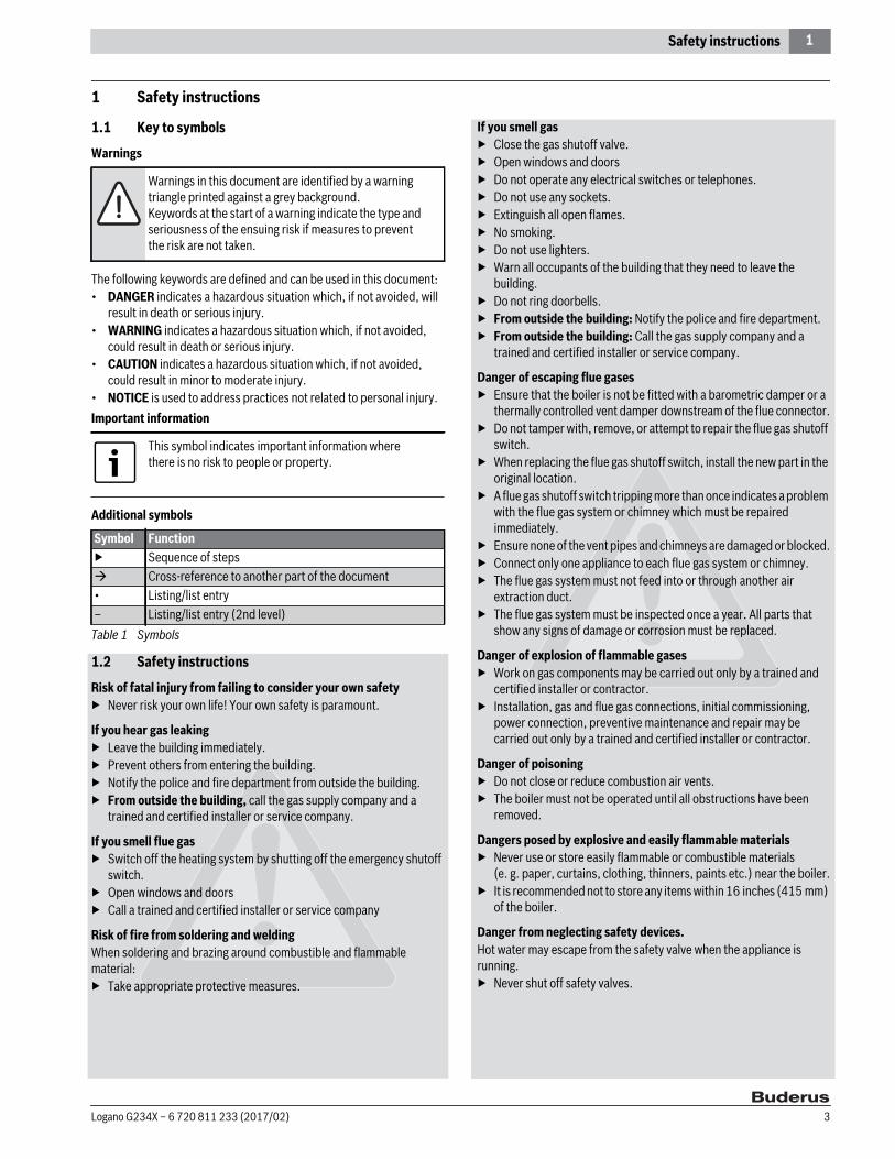
1.1 Key to symbols
Warnings
The following keywords are defined and can be used in this document:• DANGER indicates a hazardous situation which, if not avoided, will
result in death or serious injury.• WARNING indicates a hazardous situation which, if not avoided,
could result in death or serious injury.• CAUTION indicates a hazardous situation which, if not avoided,
could result in minor to moderate injury.• NOTICE is used to address practices not related to personal injury.Important information
Additional symbols
1.2 Safety instructions
Risk of fatal injury from failing to consider your own safety▶ Never risk your own life! Your own safety is paramount.
If you hear gas leaking▶ Leave the building immediately.▶ Prevent others from entering the building.▶ Notify the police and fire department from outside the building.▶ From outside the building, call the gas supply company and a
trained and certified installer or service company.
If you smell flue gas▶ Switch off the heating system by shutting off the emergency shutoff
switch.▶ Open windows and doors▶ Call a trained and certified installer or service company
Risk of fire from soldering and weldingWhen soldering and brazing around combustible and flammable material:▶ Take appropriate protective measures.
If you smell gas▶ Close the gas shutoff valve.▶ Open windows and doors▶ Do not operate any electrical switches or telephones.▶ Do not use any sockets.▶ Extinguish all open flames. ▶ No smoking. ▶ Do not use lighters.▶ Warn all occupants of the building that they need to leave the
building.▶ Do not ring doorbells.▶ From outside the building: Notify the police and fire department.▶ From outside the building: Call the gas supply company and a
trained and certified installer or service company.
Danger of escaping flue gases▶ Ensure that the boiler is not be fitted with a barometric damper or a
thermally controlled vent damper downstream of the flue connector.▶ Do not tamper with, remove, or attempt to repair the flue gas shutoff
switch.▶ When replacing the flue gas shutoff switch, install the new part in the
original location.▶ A flue gas shutoff switch tripping more than once indicates a problem
with the flue gas system or chimney which must be repaired immediately.
▶ Ensure none of the vent pipes and chimneys are damaged or blocked.▶ Connect only one appliance to each flue gas system or chimney.▶ The flue gas system must not feed into or through another air
extraction duct.▶ The flue gas system must be inspected once a year. All parts that
show any signs of damage or corrosion must be replaced.
Danger of explosion of flammable gases▶ Work on gas components may be carried out only by a trained and
certified installer or contractor.▶ Installation, gas and flue gas connections, initial commissioning,
power connection, preventive maintenance and repair may be carried out only by a trained and certified installer or contractor.
Danger of poisoning▶ Do not close or reduce combustion air vents.▶ The boiler must not be operated until all obstructions have been
removed.
Dangers posed by explosive and easily flammable materials▶ Never use or store easily flammable or combustible materials
(e. g. paper, curtains, clothing, thinners, paints etc.) near the boiler.▶ It is recommended not to store any items within 16 inches (415 mm)
of the boiler.
Danger from neglecting safety devices.Hot water may escape from the safety valve when the appliance is running.▶ Never shut off safety valves.
Warnings in this document are identified by a warning triangle printed against a grey background.Keywords at the start of a warning indicate the type and seriousness of the ensuing risk if measures to prevent the risk are not taken.
This symbol indicates important information where there is no risk to people or property.
Symbol Function▶ Sequence of steps Cross-reference to another part of the document• Listing/list entry– Listing/list entry (2nd level)
Table 1 Symbols
Logano G234X – 6 720 811 233 (2017/02) 3

2 Product Description
Danger of electric shock when the boiler is open.Before opening the boiler:▶ Disconnect the heating system from the electrical power supply via
the ON/OFF switch or the appropriate building fuse. It is not sufficient just to switch off the controller. Power to the controller must be disconnected.
▶ Take measures to ensure that the heating system cannot be accidentally reactivated.
▶ Electrical work may be carried out only by qualified and certified electricians.
Danger due to short-circuitsTo prevent short circuits:▶ Only genuine Buderus wiring replacement parts.▶ Do not attempt to operate an appliance if any part of it has been
under water. ▶ Replace any appliance that has been under water.
Risk of system damage due to contaminated combustion air supply▶ Keep the combustion air free of corrosive substances, e.g.
halogenated hydrocarbons from painting operations or beauty salons.
▶ Keep combustion air free from dust and lint (e. g. from nearby laundry or agricultural operations).
▶ If clean room air is not available, fresh outdoor combustion air must be provided.
Risk of system damage in the event of improper operation▶ Use the boiler only for its intended purpose.▶ Operate the boiler only if it has been installed and maintained per the
instructions provided in the Installation Manual.▶ Do not attempt to operate an appliance if any part of it is not in
working order or is damaged.▶ Use only original spare parts. The use of parts not supplied by the
manufacturer may cause damage to the boiler, other property and personal injury. Also, boiler damage caused by the use of unauthorized parts is not covered by the warranty.
▶ With sealed combustion appliances: do not cover or reduce the size of air inlet and ventilation openings in doors, windows and walls.
▶ If draft-proof windows are installed, ensure an adequate supply of combustion air.
Notice regarding regulations and legal requirements▶ The installation must comply with all applicable national, state, and
local codes, rules, and regulations.▶ The operator is responsible for the operational safety and regulatory
compliance of the heating system.
Instructing the owner/operator▶ The installer must instruct the owner and operator on the
functionality of the components and the proper operation of the boiler and the heating system.
▶ Upon completion of the installation, these instructions should be handed to the owner and operator of the appliance.
▶ Inform the owner/operator that they must never carry out any modifications or repairs.
2 Product DescriptionThis installation and maintenance manual contains important information for the safe and correct installation, initial commissioning, and maintenance of this boiler.The Logano G234X floor-standing gas boiler is generally referred to below as a boiler. The installation and maintenance manual is provided for technicians who have been trained and have experience in working with heating systems and oil- and gas-fired installations.▶ Use the boiler only in the combinations and with the accessories and
spare parts that are specified in the installation and maintenance instructions.
▶ Other combinations, other accessories and spare parts must only be used if they are specifically designed for the intended application and do not affect the system performance and the safety requirements.
2.1 Designated useThe boiler is designed for heating central heating system water and indirect provision of domestic hot water (e.g. in a hot water storage tank) in residential buildings or apartment buildings. Any other purpose is considered improper use.
2.2 Standards, regulations and directives
2.2.1 National regulations The design and mode of operation of this boiler comply with the American National Standard ANSI Z21.13/CSA4.9, latest edition for Gas-Fired Low-Pressure Steam and Hot Water Boilers.Other confirmed approvals and certifications are indicated by stickers on the boiler.Installation of the boiler must comply with all applicable codes and regulations imposed by the national, state or local authorities and bodies. The relevant authorities and regulatory bodies must be informed before installation starts.If no specific requirements are defined, the latest edition of the National Fuel Gas Code ANSI Z223.1/NFPA 54 must be complied with for all installations in the USA. Installations in Canada must comply with the latest edition of the Installation Code for Gas Burning Appliances and Equipment, CAN/CSA-B.149. Where required by local authorities, the system must comply with the American Society of Mechanical Engineers Safety Code for Controls and Safety Devices for Automatically Fired Boilers (ASME CSD-1).Carbon monoxide detectors must be installed as specified by the local regulations. Boiler requires yearly maintenance.
2.2.2 Boiler operating conditions Maximum boiler temperature: 210 °F (99 °C)Maximum operating pressure: 58 psi (4 bar)The hot water piping system must comply with all applicable codes and regulations. If an existing boiler is being replaced, the entire hot water piping system must be inspected to ensure that it is in suitable condition to assure safe operation.
For the installation and operation of the heating system, observe all country-specific standards and guidelines!
Logano G234X – 6 720 811 233 (2017/02)4

2 Product Description
2.3 Notes on installation and operationWhen installing and operating the heating system, observe and comply with the following:• The local building codes regarding the installation.• The local building regulations regarding air supply and venting
systems and the chimney flue connection.• Regulations governing power connection to the power supply.• The technical regulations of the gas utility company regarding the
connection of the gas burner to the local main gas supply.• The regulations and standards relating to the safety systems for hot-
water heating systems.
2.3.1 Other important information• The installation of a boiler must be notified to and approved by the
relevant gas supply company.• Operate the boiler only with the balanced flue system (LAS)
specifically designed and approved for this boiler type.• Regional approvals for the flue gas system may be required.
2.4 Tools, materials and equipmentFor the installation and maintenance of the boiler, you will need the standard tools used for central heating, gas and water systems plus a set of metric wrenches and Allen wrenches.The following assembly aids will also be useful:• Pipes for transport• Wood battens• Cleaning brushes and/or chemical cleaning agent for wet cleaning
2.5 Disposal▶ Dispose of the boiler packaging material in an environmentally
responsible fashion.▶ Dispose of any components of the heating system that require
replacement in an environmentally responsible fashion at an approved landfill.
Notice regarding environmental protection and disposal Section 8, page 24.
2.6 Product DescriptionThe boiler is a low-temperature gas boiler with an atmospheric gas burner.
The boiler consists of the following main components ( Fig. 1):• Ignition module and adjustable boiler temperature controller• Boiler casing and front cover• Boiler block with insulation• BurnersThe ignition module and adjustable boiler temperature controller monitor and control all electrical and operational components of the boiler.The boiler casing prevents energy loss and acts as soundproofing. The boiler block transfers the heat generated by the burner to the boiler water. The insulation reduces energy loss.
Fig. 1 Main components G234X
[1] AquaSmartTM [2] Ignition control[3] Boiler block with insulation[4] Boiler jacket[5] Burners[6] Front cover of boiler
2.7 Scope of delivery▶ Check packaging upon receipt of delivery for damage.▶ Check delivery for completeness.The boiler is supplied in one packing unit with the mounted boiler casing, gas burner and gas valve, and technical documentation.
The following accessories are optionally available from Buderus:• CH Pump • Cleaning brush
The boiler is fully functional with the factory-installed AquaSmartTM.
Component Qty. Packaging methodBoiler 1 Pallets/box• 90 °-elbow (¾ " NPT)• Safety valve• Drain valve (¾ ")
1 Box
Vent damper 1 BoxTechnical documentation 1 Foil package
Table 2 Scope of delivery
6
1
2
3
5
4
6 720 806 028-01.1T
Logano G234X – 6 720 811 233 (2017/02) 5
2 Product Description
2.8 Dimensions and Specifications
2.8.1 Logano G234X dimensions
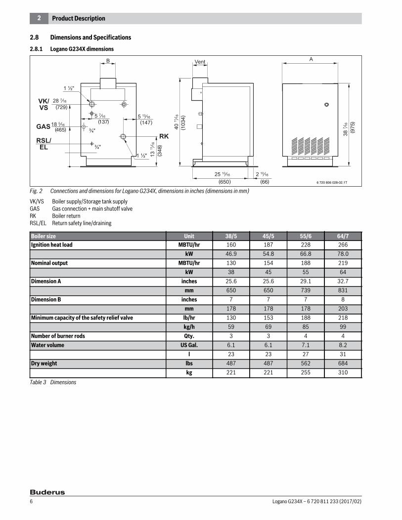
Fig. 2 Connections and dimensions for Logano G234X, dimensions in inches (dimensions in mm)
VK/VS Boiler supply/Storage tank supplyGAS Gas connection + main shutoff valveRK Boiler returnRSL/EL Return safety line/draining
1 ½ʺ
28 7⁄16
18 5⁄16 5 7⁄16 5 13⁄16
1 ½ʺ
¾ʺ
¾ʺ 13
11⁄16
40 11
⁄16
25 10⁄16 2 10⁄16
38 7 ⁄1
6
729
465
137 147
348
650 6610
34
975
6 720 806 028-02.1T
Boiler size Unit 38/5 45/5 55/6 64/7Ignition heat load MBTU/hr 160 187 228 266
kW 46.9 54.8 66.8 78.0Nominal output MBTU/hr 130 154 188 219
kW 38 45 55 64Dimension A inches 25.6 25.6 29.1 32.7
mm 650 650 739 831Dimension B inches 7 7 7 8
mm 178 178 178 203Minimum capacity of the safety relief valve lb/hr 130 153 188 218
kg/h 59 69 85 99Number of burner rods Qty. 3 3 4 4Water volume US Gal. 6.1 6.1 7.1 8.2
l 23 23 27 31Dry weight lbs 487 487 562 684
kg 221 221 255 310Table 3 Dimensions
Logano G234X – 6 720 811 233 (2017/02)6
2 Product Description
2.8.2 Technical Data
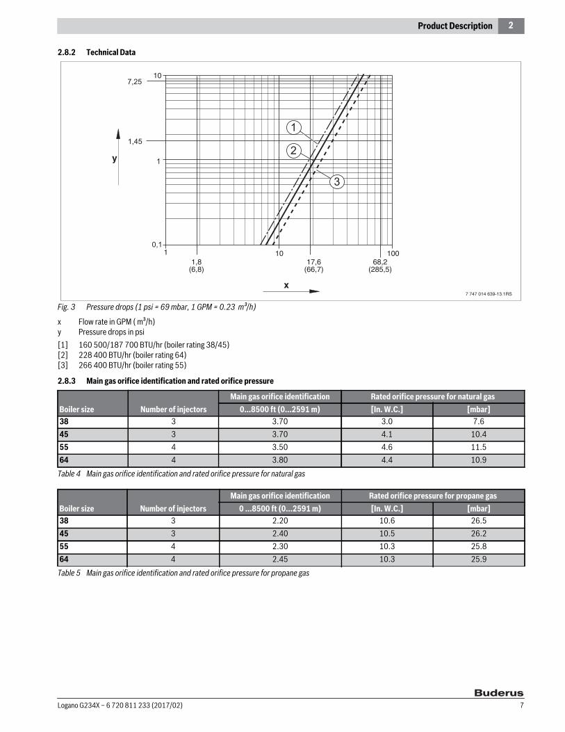
Fig. 3 Pressure drops (1 psi = 69 mbar, 1 GPM = 0.23 m³/h)
x Flow rate in GPM ( m³/h)y Pressure drops in psi[1] 160 500/187 700 BTU/hr (boiler rating 38/45)[2] 228 400 BTU/hr (boiler rating 64)[3] 266 400 BTU/hr (boiler rating 55)
2.8.3 Main gas orifice identification and rated orifice pressure
Boiler size Number of injectorsMain gas orifice identification Rated orifice pressure for natural gas
0...8500 ft (0...2591 m) [In. W.C.] [mbar]38 3 3.70 3.0 7.645 3 3.70 4.1 10.455 4 3.50 4.6 11.564 4 3.80 4.4 10.9
Table 4 Main gas orifice identification and rated orifice pressure for natural gas
Boiler size Number of injectorsMain gas orifice identification Rated orifice pressure for propane gas
0 ...8500 ft (0...2591 m) [In. W.C.] [mbar]38 3 2.20 10.6 26.545 3 2.40 10.5 26.255 4 2.30 10.3 25.864 4 2.45 10.3 25.9
Table 5 Main gas orifice identification and rated orifice pressure for propane gas
Logano G234X – 6 720 811 233 (2017/02) 7
3 Moving the tank
3 Moving the tankThis section details how to move the boiler safely.
Moving the boiler with boiler cart
▶ Position transport equipment (e. g. hand truck) at the back of the boiler.
▶ Secure packaged boiler to the hand truck.▶ Move the packaged boiler to the installation location.
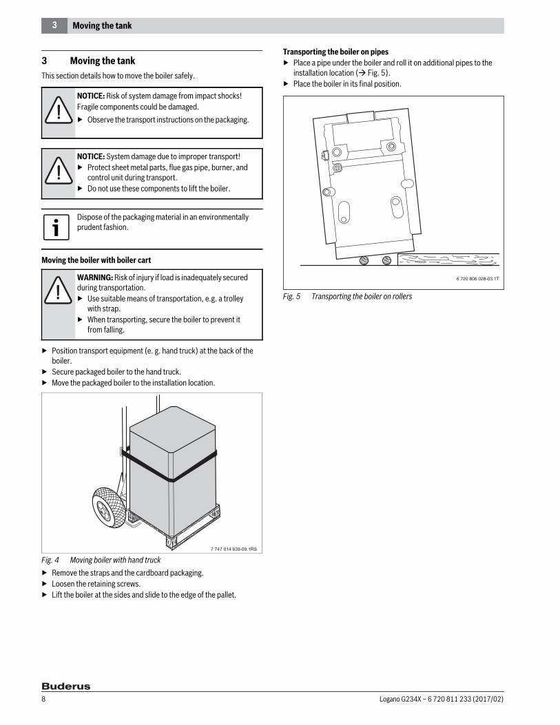
Fig. 4 Moving boiler with hand truck▶ Remove the straps and the cardboard packaging.▶ Loosen the retaining screws.▶ Lift the boiler at the sides and slide to the edge of the pallet.
Transporting the boiler on pipes▶ Place a pipe under the boiler and roll it on additional pipes to the
installation location ( Fig. 5).▶ Place the boiler in its final position.
Fig. 5 Transporting the boiler on rollers
NOTICE: Risk of system damage from impact shocks!Fragile components could be damaged.▶ Observe the transport instructions on the packaging.
NOTICE: System damage due to improper transport!▶ Protect sheet metal parts, flue gas pipe, burner, and
control unit during transport.▶ Do not use these components to lift the boiler.
Dispose of the packaging material in an environmentally prudent fashion.
WARNING: Risk of injury if load is inadequately secured during transportation.▶ Use suitable means of transportation, e.g. a trolley
with strap.▶ When transporting, secure the boiler to prevent it
from falling.
6 720 806 028-03.1T
Logano G234X – 6 720 811 233 (2017/02)8

4 Placing the boiler
4 Placing the boilerThis section explains how to set up and position the boiler correctly at the installation location.
4.1 Installation location requirements
4.2 Clearances Position the boiler with the recommended wall clearances. Reducing these to the minimum clearances makes the boiler more difficult to access.The base or foundation on which the boiler is to stand must be perfectly flat and level. The boiler may stand on a base made of combustible material, but not on carpet.
A space of at least 33 inches (840 mm) is required in front of the boiler with the door open to allow sufficient accessibility for operation and maintenance. When the door is closed, a minimum clearance of 2 inches (50 mm) is required at the front and sides, a wall clearance of 6 inches (155 mm) is also required for the flue pipe and 30 inches (762 mm) clearance to the ceiling.
Fig. 6 Wall clearances in the boiler room
[1] Closed door[2] Open door
4.3 Leveling the boilerThe boiler must be leveled horizontally and vertically to prevent air pockets forming inside.▶ Level the boiler both horizontally and vertically using a spirit level. ▶ Insert metal shims underneath if necessary.
Fig. 7 Leveling the boiler (example)
DANGER: Danger posed by explosive and combustible materials!▶ Never use or store easily flammable materials (paper,
curtains, clothing, thinners, paints etc.) near the boiler.
▶ Maintain a clearance of 16 inches (415 mm) from the boiler.
NOTICE: Risk of system damage due to freezing!▶ Install the heating system that it will not be exposed
to freezing conditions.
NOTICE: Damage to the building due to insufficient load capacity of the floor!▶ Before setting the boiler up, check the load capacity
of the floor.
NOTICE: Boiler damage due to contaminated combustion air. ▶ Do not use cleaning agents that contain chlorine or
halogenated hydrocarbons (e.g. in spray cans, solvents and cleaning agents, paints, glues).
▶ Avoid excessive dust accumulation (building dust).
Wall clearanceDimension [inch] [mm]A 33 840B 6 155C 2 50
Table 6 Wall clearances
Where applicable, allow extra wall clearances for additional components such as a DHW tank, pipe joints, vent pipe silencer or other components on the flue gas side, etc.
NOTICE: Risk of system damage due to contamination!▶ If the boiler is not to be installed immediately, protect
the connections from entry of dirt.
1
2
6 720 806 028-05.1T
6 720 806 028-04.1T
Logano G234X – 6 720 811 233 (2017/02) 9

5 Boiler installation
5 Boiler installationThis section details how to install your boiler correctly. This involves the following steps:• Vent connection• Heating circuit connection• Electrical connections• Connecting the fuel supply
5.1 Preparing for installation▶ Unpack all cartons and boxes.▶ Using the included packing list, check to be sure that you have all the
included parts.
Route the gas connection towards the left
If the gas connection needs to be on the left:▶ Loosen the unions on the gas supply pipe completely.▶ Reattach and seal the gas supply pipe after rotating it 180 °.▶ Carry out leak test.
5.2 Connecting the heating systemThis section explains how the boiler is connected to the heating system.
5.2.1 Safety instructions
Fig. 8 Low water indicator
A Heating system with low water indicatorB Heating system without low water indicator[1] Boiler[2] Panel radiator
Every boiler is carefully inspected and tested before it leaves the factory. However, if you discover any damage or missing parts, please inform the supplier immediately. Before disposing of packing material, make sure that no parts are still in it.
The gas supply pipe is designed for a gas connection on the right side.
NOTICE: Risk of boiler damage due to moisture!▶ Protect the individual components of the control
system and the ignition system from damp (dripping water, water spray, rain) during installation, operation and servicing (e.g. pump replacement, programmer replacement, etc.
NOTICE: Risk of system damage due to overheating as a result of lack of water!▶ Make sure that if the boiler is located above the level
of the heating system, it is fitted with a low water indicator.
▶ The low water indicator must be installed when the boiler is installed ( Fig. 8).
NOTICE: Risk of system damage due to high temperature variations in the heating system!▶ If the boiler is operated in conjunction with an air
conditioning system, it is essential to ensure that the pipes for the refrigerant fluid are connected in parallel with the boiler system by means of suitable valves to prevent the refrigerant from entering the boiler. This prevents refrigerant fluid from entering the boiler.
▶ If the boiler piping is connected to the heating coils of a hot-air heating system, these may be exposed to the circulation of cool air. In this case, the boiler piping must be equipped with a flow-control valve or some other automatic system for preventing the boiler water from circulating by gravity during the cooling cycle.
NOTICE: Risk of system damage due to leaking connections!▶ Connect pipes without stress to the boiler
connections.
1
2
2
1
2
2
2
2
A
B
6 720 806 028-06.1T
Logano G234X – 6 720 811 233 (2017/02)10

5 Boiler installation
5.2.2 Connect the central heating supply and return
Connecting the safety valve in the central heating supply
▶ Install the included supply manifold and the 90 ° elbow.▶ Do not install the safety valve until the leak test has been completed.
Fig. 9 Supply connection
[1] Boiler[2] Safety valve[3] Supply manifold pipe (factory-installed)[4] 90 °-elbow (¾ " NPT)[5] Supply connection
5.3 Electrical connections
The electrical connections to the boiler must conform to the locally applicable regulations and the relevant requirements of the National Electrical Code, ANSI/NFPA-70. In Canada the regulations of CSA C22.1 Canadian Electrical Code, Part 1, must be observed.The boiler must be grounded in accordance with the regulations of the relevant authorities or else the requirements of the National Electrical Code, ANSI/NFPA-70.
Connecting the power supply▶ Establish a permanent connection to the factory-installed
AquaSmartTM in accordance with the locally applicable regulations.▶ Mount an ON/OFF switch near the boiler.
Fig. 10 Main power switch (by customer)
DANGER: Risk of fire from flammable materials!▶ Maintain a clearance of 2 inches (51 mm) from pipes
carrying hot water and flammable walls at the installation location.
We recommend installing a dirt trap and a dirt separator (accessory) in the heating return connection to reduce build-up of debris on the water side.
Observe the local regulations for connection of boiler systems.
NOTICE: System damage due to faulty safety valve!During the leak test, the safety valve can be damaged.▶ Do not install the safety valve until the leak test
( Section 5.5 Filling heating system and checking for leaks, page 13) has been completed.
1
2
3
4
5
6 720 806 028-17.1T
DANGER: Danger to life from electric shock!▶ Carry out electrical work on the heating system only
if you are properly qualified for the work in question. If you do not have the proper qualifications, have the work done by a suitably qualified electrician.
▶ Observe the local regulations.▶ Incorrectly terminated cables can result in faulty
operation and possibly dangerous consequences. When making the electrical connections follow the wiring diagrams on page 32.
6 720 806 028-18.1T
Logano G234X – 6 720 811 233 (2017/02) 11
5 Boiler installation
5.4 Fuel gas supply connection
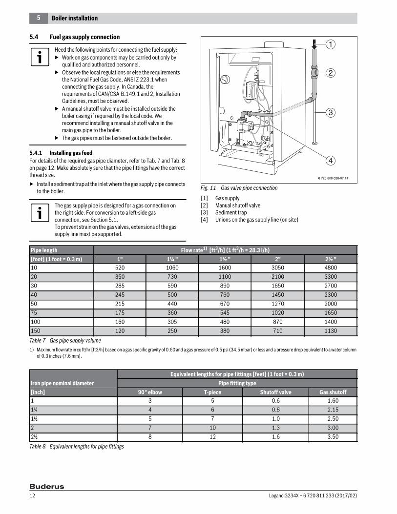
5.4.1 Installing gas feedFor details of the required gas pipe diameter, refer to Tab. 7 and Tab. 8 on page 12. Make absolutely sure that the pipe fittings have the correct thread size.▶ Install a sediment trap at the inlet where the gas supply pipe connects
to the boiler. Fig. 11 Gas valve pipe connection
[1] Gas supply[2] Manual shutoff valve[3] Sediment trap[4] Unions on the gas supply line (on site)
Heed the following points for connecting the fuel supply:▶ Work on gas components may be carried out only by
qualified and authorized personnel.▶ Observe the local regulations or else the requirements
the National Fuel Gas Code, ANSI Z 223.1 when connecting the gas supply. In Canada, the requirements of CAN/CSA-B.149.1 and 2, Installation Guidelines, must be observed.
▶ A manual shutoff valve must be installed outside the boiler casing if required by the local code. We recommend installing a manual shutoff valve in the main gas pipe to the boiler.
▶ The gas pipes must be fastened outside the boiler.
The gas supply pipe is designed for a gas connection on the right side. For conversion to a left-side gas connection, see Section 5.1.To prevent strain on the gas valves, extensions of the gas supply line must be supported.
1
2
3
4
6 720 806 028-07.1T
Pipe length Flow rate1) [ft3/h] (1 ft3/h = 28.3 l/h)
1) Maximum flow rate in cu ft/hr [ft3/h] based on a gas specific gravity of 0.60 and a gas pressure of 0.5 psi (34.5 mbar) or less and a pressure drop equivalent to a water column of 0.3 inches (7.6 mm).
[foot] (1 foot = 0.3 m) 1" 1¼ " 1½ " 2" 2½ "10 520 1060 1600 3050 480020 350 730 1100 2100 330030 285 590 890 1650 270040 245 500 760 1450 230050 215 440 670 1270 200075 175 360 545 1020 1650100 160 305 480 870 1400150 120 250 380 710 1130
Table 7 Gas pipe supply volume
Equivalent lengths for pipe fittings [feet] (1 foot = 0.3 m)Iron pipe nominal diameter Pipe fitting type[inch] 90 ° elbow T-piece Shutoff valve Gas shutoff1 3 5 0.6 1.601¼ 4 6 0.8 2.151½ 5 7 1.0 2.502 7 10 1.3 3.002½ 8 12 1.6 3.50
Table 8 Equivalent lengths for pipe fittings
Logano G234X – 6 720 811 233 (2017/02)12

5 Boiler installation
Leak test
▶ Test the boiler and gas supply connections for leaks ( page 18).
Pressure testsDisconnect the boiler with the attached manual shutoff valve and physically separate the boiler from the gas supply piping if the gas supply piping system is pressure-tested with a test pressure greater than 0.5 psi (34.5 mbar).If the gas supply piping system is pressure-tested at a test pressure of 0.5 psi (34.5 mbar) or less, it is sufficient to disconnect the boiler from the gas supply piping system by closing the shutoff valve.
5.4.2 Converting boiler to propaneThe boiler is factory-set for operation with natural gas.
5.5 Filling heating system and checking for leaksThe boiler is tested for leaks at the factory. Before putting the heating system into operation, it must be checked to ensure that no leaks will occur during operation.
▶ Seal off connection for safety valve in the heating supply and all other unused connections with plugs.
▶ Isolate the expansion tank from the system by closing the cap valve.▶ Open the mixing and shutoff valves on the heating water (primary)
side.
DANGER: Risk of explosion!Leakage from the gas pipes and gas connections may cause an explosion.▶ Carry out a proper leakage test using leak detector
fluid.
NOTICE: Risk of system damage due to short-circuits!▶ Cover the areas at risk before carrying out the
leakage test.▶ Do not spray leak detector onto cable conduits, plugs
or electrical connecting leads or allow it to drip onto them.
Use only sealing compound that is resistant to corrosion by LPG for the pipe connections. The sealing compound must be applied sparingly to the male thread of the pipe connections.
Conversion kits for converting the boiler from natural gas to propane gas can be obtained from Bosch. Do not attempt to convert the appliance without the approved Buderus parts and the relevant technical documentation. The technical documentation is included with the conversion parts.
For information about the identification of the main gas orifice and the nominal gas orifice pressure for natural gas and propane gas, see Section 2.8.3, page 7.
WARNING: Risk of system damage due to excess pressure when testing for leaks!Pressure, control and safety equipment may be damaged by excessive pressure.▶ When you carry out a leak test, make sure that no
pressure, control or safety device that cannot be isolated from the boiler's water chamber is installed.
WARNING: Health risk from contaminated domestic water!▶ Always observe the regulations and standards
applicable in your jurisdiction for the prevention of contamination of drinking water (e. g. by water from heating systems).
NOTICE: Risk of damage to system due to temperature stress! If you fill the heating system when it is hot, the resulting temperature stress can cause stress cracks. The boiler will then leak.▶ Only fill the heating system when it is in a cold state.
Maximum permissible supply temperature 100 °F (38 °C).
Water treatment▶ Have the water analyzed before filling the heating
system.▶ Compare the results of this analysis with the
technical documentation on water quality for boiler water.
▶ Please consult the local water supply company if there are major differences, such as extremely hard water or a pH value < 7.0.
Carry out the leak test at 1.5 times the normal operating pressure ( Tab. 9) and in accordance with the local regulations.
Maximumoperating pressure
Maximumtest pressure
30 psi (2.1 bar)with the included safety valve
45 psi (3.1 bar)
58 psi (4 bar)with a different safety valve
75 psi (5.2 bar)
Table 9 Test pressures
Logano G234X – 6 720 811 233 (2017/02) 13
5 Boiler installation
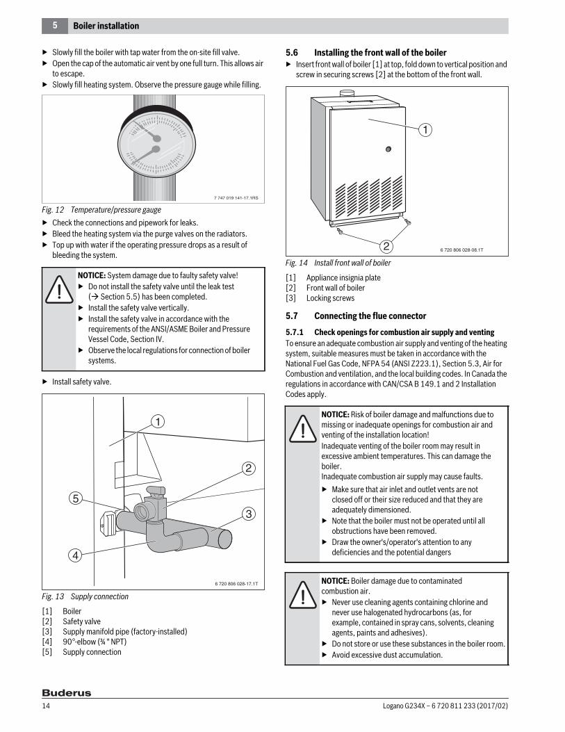
▶ Slowly fill the boiler with tap water from the on-site fill valve.▶ Open the cap of the automatic air vent by one full turn. This allows air
to escape.▶ Slowly fill heating system. Observe the pressure gauge while filling.
Fig. 12 Temperature/pressure gauge▶ Check the connections and pipework for leaks.▶ Bleed the heating system via the purge valves on the radiators.▶ Top up with water if the operating pressure drops as a result of
bleeding the system.
▶ Install safety valve.
Fig. 13 Supply connection
[1] Boiler[2] Safety valve[3] Supply manifold pipe (factory-installed)[4] 90 °-elbow (¾ " NPT)[5] Supply connection
5.6 Installing the front wall of the boiler▶ Insert front wall of boiler [1] at top, fold down to vertical position and
screw in securing screws [2] at the bottom of the front wall.
Fig. 14 Install front wall of boiler
[1] Appliance insignia plate[2] Front wall of boiler [3] Locking screws
5.7 Connecting the flue connector
5.7.1 Check openings for combustion air supply and ventingTo ensure an adequate combustion air supply and venting of the heating system, suitable measures must be taken in accordance with the National Fuel Gas Code, NFPA 54 (ANSI Z223.1), Section 5.3, Air for Combustion and ventilation, and the local building codes. In Canada the regulations in accordance with CAN/CSA B 149.1 and 2 Installation Codes apply.
NOTICE: System damage due to faulty safety valve!▶ Do not install the safety valve until the leak test
( Section 5.5) has been completed.▶ Install the safety valve vertically.▶ Install the safety valve in accordance with the
requirements of the ANSI/ASME Boiler and Pressure Vessel Code, Section IV.
▶ Observe the local regulations for connection of boiler systems.
7 747 019 141-17.1RS
1
2
3
4
5
6 720 806 028-17.1T
NOTICE: Risk of boiler damage and malfunctions due to missing or inadequate openings for combustion air and venting of the installation location!Inadequate venting of the boiler room may result in excessive ambient temperatures. This can damage the boiler.Inadequate combustion air supply may cause faults.▶ Make sure that air inlet and outlet vents are not
closed off or their size reduced and that they are adequately dimensioned.
▶ Note that the boiler must not be operated until all obstructions have been removed.
▶ Draw the owner's/operator's attention to any deficiencies and the potential dangers
NOTICE: Boiler damage due to contaminated combustion air.▶ Never use cleaning agents containing chlorine and
never use halogenated hydrocarbons (as, for example, contained in spray cans, solvents, cleaning agents, paints and adhesives).
▶ Do not store or use these substances in the boiler room.▶ Avoid excessive dust accumulation.
2
1
6 720 806 028-08.1T
Logano G234X – 6 720 811 233 (2017/02)14

5 Boiler installation
Total air supply from inside the buildingMake sure that the installation room has two permanent air vents that are connected to one or more other rooms. When calculating the cross-sectional areas of the vent apertures, the total burner output of all gas-fired appliances in the connected rooms must be taken into account. Each vent must have a minimum cross-section of one square inch per 1000 Btu/h (2200 mm2/kW) of the total burner output of all gas-fired appliances inside the connected rooms. Make sure that the cross-sectional area of each vent is at least 100 square inches (0.06 m2). One of the vents must be no more than 12 inches (300 mm) from the ceiling and the other no more than 12 inches (300 mm) from the floor of the installation location, measured from the outer edge of the vent opening. The smallest dimension of all air intake and outlet openings must be not less than 3 inches (80 mm).
Total air supply from outside the buildingMake sure that the installation location has two permanent air vents, one of which must not be more than 12 inches (300 mm) from the ceiling and the other not more than 12 inches (300 mm) from the floor of the installation location, measured from the outer edge of the vent opening. The vents must be connected either directly or via air ducts to the outside or to rooms that have an unobstructed connection to the open air (e. g. crawl space or attic). The smallest dimension of all air intake and outlet openings must be not less than 3 inches (80 mm).• If there is a direct connection to the outside, each opening must have
a minimum cross-section of one square inch per 4000 Btu/h (550 mm2/kW) of the total combustion output of all gas-fired appliances inside the closed room.
• If there is a connection to the outside through horizontal ventilation ducts, each opening must have a minimum cross-section of one square inch per 4000 Btu/h (550 mm2/kW) of the total burner output of all gas-fired appliances inside the closed room.
• If there is a connection to the outside through vertical ventilation ducts, each opening must have a minimum cross-section of one square inch per 2000 Btu/h (1100 mm2/kW) of the total burner output of all gas-fired appliances inside the closed room.
• If the openings are connected to ventilation ducts, the ducts must have the same cross-section area as the openings to which they connected.
5.7.2 Requirements for connection to chimneys or flue gas systems
The flue connection must comply with the regulations of the National Fuel Gas Code NFPA 54, Part 7, Venting of Equipment, and the local building codes. In Canada the regulations of CAN/CSA B 149.1 as well as local building codes apply.Flue connections of boilers with natural venting must not be connected with any component of a mechanically operated flue gas system (blower-assisted) that operates with overpressure. The cross-section of the flue connection must not be less than that specified in Tab. 10.
If the boiler will be connected to a masonry chimney:▶ Inspect the chimney thoroughly beforehand. ▶ The chimney must be clean, in compliance with construction codes
and of sufficient dimensions.Chimneys with an internal liner are preferred and are only permitted if the liner complies with all national, state and local construction codes. Liners of fire-glazed brick with moisture-proof joints and liners of corrosion-resistant material are recommended.Contact the local gas supply utility for advice and recommendations for flue connection and chimney liners. A flue pipe of single-walled sheet metal is required for flue connections for type II appliances. An adequate chimney height in compliance with the tables of the National Fuel Gas Code, ANSI Z 223.1, is required.
Disconnecting a boiler from a common flue gas systemIf an existing boiler is disconnected from a common flue gas system, the flue gas system is now oversized. Proper venting for the remaining heating systems is then no longer guaranteed.
If impurities in the combustion air are possible (e. g. installation near swimming pools, dry cleaners or hairdressing salons), sealed combustion is recommended.
Boiler size Diameter of the flue gas connector [inch] [mm]
38 7 17845 7 17855 7 17864 8 203
Table 10 Cross-section of the flue gas connection
Logano G234X – 6 720 811 233 (2017/02) 15

5 Boiler installation
Procedure for checking the flue gas system:Carry out these steps with every heating system that remains connected to the flue gas system when the boiler is disconnected from a flue header. Operate the heating system that is to be disconnected from the flue header, while the other heating systems connected to the flue gas system remain off.
In Canada the regulations in accordance with CAN/CSA B 149.1 and 2 Installation Codes apply.
5.7.3 Installing the flue pipe
▶ Attach vent pipe to flue outlet of draft hood.▶ Fasten the vent pipe with four (4) corrosion-resistant sheet metal
screws.
5.7.4 Connecting flue pipeUse only vent pipes with the proper diameter for the boiler. Every horizontal section of the flue gas routing pipe run must have a minimum rise of ¼ inches/ft (21 mm/m) towards the chimney. The flue pipe must be securely fastened to prevent it from sagging. A suspension must be installed at least every 5 feet (1.5 m). Fasten every connection with at least three (3) corrosion-resistance sheet metal screws. The end section of the flue gas routing pipe must connect to the inside of the chimney smoke duct.A minimum clearance of 6 inches (155 mm) is required between the vent pipes and all flammable materials.The flue pipe must not be reduced in size and venting must not be prevented by the installation of additional components. ▶ Connect vent pipe to the chimney with the shortest possible length of
vent pipe.
5.7.5 Installing a vent damper▶ Use only the vent damper supplied with the boiler for the flue outlet
on the boiler.
The position of the vent damper position blade must be visible.The flue gas collector must be at least 6 inches (155 mm) from all flammable components.The vent damper must be readily accessible for preventive maintenance.The vent damper must be open when the main burner of the boiler is operating. ▶ Place flue connector adapter [3] on the collar of the draft hood [4].▶ Install pins in the holes provided in the vent damper [1].▶ Fasten vent damper to the flue connector adapter with three (3)
corrosion-resistant sheet metal screws.
A Seal all unused openings of the common flue gas system.B Perform a visual inspection of the flue gas system to ensure that
it has the correct dimensions and longitudinal inclination. Make sure that the system is not blocked, leaking, corroded or has any other faults that cause it to operate improperly.
C If necessary, close all doors and windows of the building. Also close all doors leading to other rooms of the building at the location where the heating systems still connected to the flue gas system are located. Switch off dryers and all appliances that are not connected to the flue gas system. Operate all venting fans and bathroom exhaust fans at their highest speed. Fans in use in summer must remain in operation and oven exhaust system flaps must be closed.
D Start up the heating system to be tested. Follow the instructions for commissioning. Set the thermostat for continuous operation.
E After the main gas burner has been operating for five minutes, check the opening at the flue gas collector for drafts with an open flame, or with the smoke of a cigarette, cigar or pipe.
F Perform this check on all heating systems that remain connected to the flue gas system to ensure that the flue gases are vented properly. Then place all doors, windows, venting fans, exhaust system flaps, and all other gas-fired appliances back into their original state.
G Any incorrect condition of the common flue gas system must be corrected to ensure that the heating system complies with the regulations of the National Fuel Gas Code, ANSI Z 223.1. If the size of any component of the common flue gas system is changed, the complete flue gas system must be resized to comply with the relevant tables in Part 11 of the National Fuel Gas Code, ANSI Z 223.1.
DANGER: Risk of fatal injury from escaping flue gases!A flue gas collector that does not work properly can allow dangerous flue gases to escape.▶ Do not change the flue gas collector.
In Canada the vent damper must not be installed on a propane-fired heating system with a electronic ignition system.
Logano G234X – 6 720 811 233 (2017/02)16
5 Boiler installation
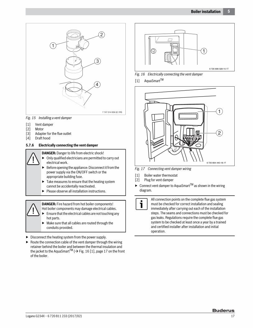
Fig. 15 Installing a vent damper
[1] Vent damper[2] Motor[3] Adapter for the flue outlet[4] Draft hood
5.7.6 Electrically connecting the vent damper
▶ Disconnect the heating system from the power supply. ▶ Route the connection cable of the vent damper through the wiring
retainer behind the boiler and between the thermal insulation and the jacket to the AquaSmartTM ( Fig. 16 [1], page 17 on the front of the boiler.
Fig. 16 Electrically connecting the vent damper
[1] AquaSmartTM
Fig. 17 Connecting vent damper wiring
[1] Boiler water thermostat[2] Plug for vent damper▶ Connect vent damper to AquaSmartTM as shown in the wiring
diagram.
DANGER: Danger to life from electric shock!▶ Only qualified electricians are permitted to carry out
electrical work.▶ Before opening the appliance: Disconnect it from the
power supply via the ON/OFF switch or the appropriate building fuse.
▶ Take measures to ensure that the heating system cannot be accidentally reactivated.
▶ Please observe all installation instructions.
DANGER: Fire hazard from hot boiler components!Hot boiler components may damage electrical cables.▶ Ensure that the electrical cables are not touching any
hot parts.▶ Make sure that all cables are routed through the
conduits provided.
All connection points on the complete flue gas system must be checked for correct installation and sealing immediately after carrying out each of the installation steps. The seams and connections must be checked for gas leaks. Regulations require the complete flue gas system to be checked at least once a year by a trained and certified installer after installation and initial operation.
1
6 720 806 028-10.1T
1
2
6 720 804 440-18.1T
Logano G234X – 6 720 811 233 (2017/02) 17

6 Placing the heating system in operation
6 Placing the heating system in operation▶ Complete the commissioning report during the commissioning
procedure ( page 23).
6.1 Testing the safety valveThe safety valve must open and relieve pressure when the set operating pressure is exceeded. If the safety valve fails to release excess pressure, it must be replaced, because otherwise system components may be damaged by excessive operating pressure.
6.2 Making the heating system ready for operationThe burner/gas valve unit integrated in the boiler have been tested in the factory as described in detail in ANSI Z 21.13 and CSA 4.9 to ensure safe operation of the heating system and to test specific performance features.
1. Set the room thermostats to the lowest setting.2. Inspect flue gas and combustion air piping and the openings for
combustion air supply and ventilation.3. Fill heating system with water and bleed the complete system,
including the radiators.
Removing the front wall of the boiler4. Unscrew the locking screws [2] at the bottom of the front cover [1],
lift front cover up, pull forward and remove to the front.
Fig. 18 Removing the front wall of the boiler
[1] Front wall of boiler [2] Locking screws
Carrying out leak test5. Open the gas shutoff valve.
6. Check the gas supply line to the gas valve for leaks with soap solution. If no leaks are found, continue with step 8.
7. If leaks are detected, close the gas shutoff valve, seal the leaks, and repeat step 6.
8. Close the gas shutoff valve. Remove the screw plug from the gas supply pressure test point [2] on the gas valve in order to measure the gas supply pressure. Install pressure test port and attach a pressure gauge.
9. To measure the orifice pressure, remove the screw plug from the orifice pressure test point [3] on the gas valve. Install pressure test port and attach a pressure gauge.
Fig. 19 Gas valve
[1] ON/OFF knob (ON position) [2] Screw plug for gas supply pressure test port[3] Screw plug for orifice pressure test port10. Open the gas shutoff valve and measure the gas supply pressure to
the boiler. The supply pressure for natural gas must be between 7"...10.5" W.C. (17.4...26.2 mbar) and between 11"...13" W.C. for propane gas (27.4...32.4 mbar). If the connection pressure is not in this range with natural gas, contact your customer service technician or gas utility company. Close the gas shutoff valve.
11. Follow the startup instructions in Section 6.3.
DANGER: Risk of fatal injury from electric current when appliance is opened up!▶ Before opening the appliance:
Disconnect the heating system from the power supply completely via the ON/OFF switch or the appropriate building fuse.
▶ It is not sufficient just to switch off the controller.▶ Take measures to ensure that the heating system
cannot be accidentally reactivated.
2
1
6 720 806 028-08.1T
NOTICE: Risk of system damage due to short-circuits!▶ Cover any hazardous locations prior to locating the
leaks.▶ Do not spray leak detector onto conduits, plugs or
electrical connection cables or allow it to drip onto them.
Logano G234X – 6 720 811 233 (2017/02)18

6 Placing the heating system in operation
6.3 Start up instructions
For your own safety, read the following information carefully before commissioning:
6.4 Preparing to commission the boilerSTOP! Before commissioning:▶ Carefully read the safety instructions in Section 6.3, page 19.1. If the boiler is not commissioned directly after the installation:
Carry out another leak test ( page 18). Wait five (5) minutes until all gas has dissipated. Then check whether there is any smell of gas (including at floor level). If you smell gas: STOP! Seal leaks and repeat the leak test ( page 18).If you do not smell gas, go to the next step.
2. Open the gas shutoff valve.
Commissioning the heating system with AquaSmartTM control The boiler is fully functional with the factory-installed AquaSmartTM.3. Turn ON/OFF switch on (ON position). This turns on the boiler with all
its components.4. Make sure that the room thermostat signals a heat requirement
(set thermostat at least 10 °F above room temperature).
Fig. 20 ON/OFF switch in ON position
6.5 Then carry out commissioning work.The following commissioning work must be performed regardless of the control unit type.5. Look at the ignition module through the inspection hole
( Fig. 21 [1]) in the burner cover.
Fig. 21 Inspection hole in the burner cover
[1] Observation Port 6. Turn gas valve ON/OFF knob [1] counterclockwise to the
ON position.
DANGER: Risk of fatal injury from failure to observe the commissioning instructions and subsequent incorrect operation!Risk of fire and explosion from failure to observe the startup instructions.▶ Read the startup instructions carefully before
commissioning.
DANGER: Risk of fatal injury from gas explosion!If you smell gas there is a danger of explosion.▶ Close the gas shutoff valve.▶ Open windows and doors▶ Do not operate any electrical switches or telephones.▶ Do not use any sockets.▶ Extinguish all open flames. No smoking. Do not use
lighters.▶ Warn all occupants of the building that they need to
leave the building.▶ Do not ring doorbells.▶ From outside the building: Notify the police and fire
department.▶ From outside the building: Call the gas supply
company and a trained and certified installer or service company.
WARNING: Risk of system damage!This appliance is fitted with an ignition module that automatically starts the pilot burner.▶ Do not attempt to light the ignition flame manually.
WARNING: Risk of system damage!The following test must also be conducted at floor level, because some gas types are heavier than air and may accumulate at floor level.▶ Check for odor of gas around the heating system.
DANGER: Risk of system damage from fire or explosion!Any attempt to use force or to repair the gas shutoff valve may cause a fire or explosion.▶ Operate the ON/OFF knob on the gas valve by hand
only. ▶ Do not use any tools. ▶ If the ON/OFF knob on the gas valve cannot be
operated by hand: Do not repair it. ▶ Contact a qualified and certified service company.
NOTICE: Risk of system damage from corrosion.▶ Do not use the appliance if any part of it has been
under water.▶ Contact a qualified and certified service company.
6 720 806 028-18.1T
6 720 806 028-11.1T
Logano G234X – 6 720 811 233 (2017/02) 19

6 Placing the heating system in operation
7. The burner control unit must generate ignition sparks towards the pilot burner. The ignition flame must appear and then ignite the main burner.If the main burner does not ignite: Close the gas shutoff valve, disconnect heating system from the power supply and inform your customer service technician or gas supply company.
8. Once the main burner has ignited, the gas valve must be checked for leaks with leak detector fluid. If no leaks are found, continue with step 10.
9. If leaks are found: Turn the ON/OFF knob on the gas shutoff valve [1] clockwise to the OFF position. Disconnect heating system from the power supply and set the thermostat to the lowest setting.Seal the leaks. Repeat steps 1 and 2.For AquaSmartTM control units, continue with steps 3 and 4.Then repeat steps 7 to 10.
Fig. 22 Gas valve
[1] ON/OFF knob (ON position)[2] Screw plug for gas supply pressure test port[3] Safety screw for the orifice pressure setting[4] Screw plug for orifice pressure test port[5] Safety screw for the pilot orifice pressure setting10. Check the gas supply pressure while the boiler is operating. The
supply pressure for natural gas must be between 7"...10.5" W.C. (17.4...26.2 mbar) and between 11"...13" W.C. for propane gas (27.4...32.4 mbar). Record the measured values in the commissioning report ( page 23).
11. Check nozzle pressure. Set the orifice pressure according to Table 11 while the boiler is operating. To do so, remove the safety screw for adjusting the orifice pressure ( Fig. 23 [3]) from the gas valve. Turn the adjustment screw clockwise to increase the orifice pressure. Turn the adjustment screw counterclockwise to decrease the pressure.
12. Record the value set in the commissioning report ( page 23). Screw the safety screw for adjusting the orifice pressure [3] back into the gas valve.
Fig. 23 Gas valve
[1] ON/OFF knob (ON position)[2] Screw plug for gas supply pressure test port[3] Safety screw for the orifice pressure setting[4] Screw plug for orifice pressure test port[5] Safety screw for the pilot orifice pressure setting13. Observe ignition flame through the inspection hole in the burner
cover ( Fig. 21 [1], page 19).14. The flame must surround the flame rod by 1/2...1 1/2 inches
(15...40 mm). If this is the case continue with step 20.
Fig. 24 Correct ignition flame setting
[1] 1/2...1 1/2 inches (12.7...38.1 mm)[2] Ignition flame
15. If the ignition flame is too small or too large, the pilot orifice pressure must be adjusted with the corresponding adjustment screw.
Boiler size
Natural gas Propane[inches W.C.] [mbar]
[inches W.C.] [mbar]
38 3.0 7.6 10.6 26.545 4.1 10.4 10.5 26.255 4.6 11.5 10.3 25.864 4.4 10.9 10.3 25.9
Table 11 Orifice pressure The adjustment screw is located behind the safety screw for the pilot orifice pressure setting ( Fig. 23, [5]).
Logano G234X – 6 720 811 233 (2017/02)20

6 Placing the heating system in operation
16. Remove the safety screw for the pilot orifice pressure setting ( Fig. 23, [5]). Turn the inner adjustment screw clockwise to reduce the size of the ignition flame. Turn the inner adjustment screw counterclockwise to increase the size of the ignition flame.
17. After adjustment, tighten the safety screw for the pilot orifice pressure setting (Fig. 23, [5]) again.
18. Observe the main burner flame through the inspection hole in the burner cover ( Fig. 21 [1], page 19). The flame must have a steady and fixed contour and generally has a bluish color. If the main burner flame has the proper appearance, continue with step 21.If the main burner flame is too weak, yellow or goes out, turn the ON/OFF knob ( Fig. 23, [1]) on the gas shutoff valve clockwise to the OFF position. Close the gas shutoff valve, disconnect heating system from the power supply and inform the customer service technician or gas supply company.
Fig. 25 Main burner
[1] Main burner flame
Checking the flame sensor19. Check the safety switch by closing the gas shutoff valve. The main
burner flame ( Fig. 25) and the ignition flame ( Fig. 24) are extinguished. After no more than six (6) seconds, the main gas solenoid valve on the gas valve must close with an audible noise.
20. After 90 seconds, the burner controller must switch to locked status and stop generating sparks.
21. Disconnect the heating system from the power supply. Open the gas shutoff valve. Switch on the power supply for the appliance. A normal operating cycle must follow. If the gas valve operates correctly: Proceed to step 25.
22. If the gas valve does not operate correctly: Immediately turn the ON/OFF knob on the gas valve [1] clockwise to the OFF position. Close the gas shutoff valve. Disconnect heating system from the power supply and inform the customer service technician or gas supply company.
Fig. 26 Gas valve in OFF position
[1] ON/OFF knob (OFF position)23. Turn the gas valve ON/OFF knob [1] clockwise to the OFF position.24. Close the gas shutoff valve.25. Disconnect heating system from the power supply and set the
thermostat to the lowest setting.26. Remove pressure test port and pressure gauge for measuring the gas
supply pressure and orifice pressure from the gas valve. Close the openings with the screw plugs ( Fig. 27 [2] and [3].
27. Repeat steps 1...10 (depending on the control unit used) and step 20. This starts up the heating system again.Check the screw plugs [2] and [3] for leaks with soap solution.If no leaks are found, continue with step 31.
28. If leaks are found, close the gas shutoff valve And turn the ON/OFF knob on the gas valve [1] clockwise to the OFF position. Shut off the heating system from the power supply.Seal the leaks. Open the gas shutoff valve and repeat step 23.
29. To avoid corrosion, carefully wipe off the soap solution afterwards.
Fig. 27 Gas valve
[1] ON/OFF knob (ON position)[2] Screw plug for gas supply pressure test port[3] Screw plug for orifice pressure test port
Logano G234X – 6 720 811 233 (2017/02) 21

6 Placing the heating system in operation
Checking the AquaSmartTM
30. Check operation of the maximum AquaSmartTM setting to make sure that it switches the boiler off as soon as the boiler temperature set on the AquaSmartTM is reached. Record the result in the commissioning report ( page 23).
– Set the AquaSmartTM to the desired setting.– Replace the front wall of the boiler ( Section 5.6, page 14).
Fig. 28 Checking temperature control
[1] Adjustment keypad
6.6 Shutting off gas supply to boiler▶ Set the room thermostats to the lowest setting.▶ Disconnect the heating system from the power supply before
carrying out maintenance work.▶ Turn the gas valve ON/OFF knob ( Fig. 26 [1]) clockwise to the
OFF position. Do not use excessive force.
6.7 Inform owner/operator, hand over technical documentation
▶ Familiarize the owner/operator with the entire heating system and the operating instructions for the boiler.
▶ Hand over the technical documentation to the owner/operator.▶ Jointly sign the commissioning report.
6 720 804 440-28.1T
1
Logano G234X – 6 720 811 233 (2017/02)22
6 Placing the heating system in operation
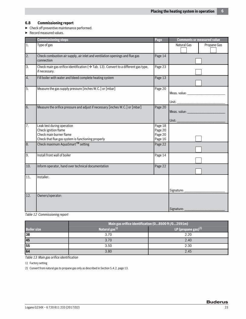
6.8 Commissioning report▶ Check off preventive maintenance performed.▶ Record measured values.
Commissioning steps Page Comments or measured value1. Type of gas Natural Gas Propane Gas
2. Check combustion air supply, air inlet and ventilation openings and flue gas connection
Page 14
3. Check main gas orifice identification ( Tab. 13). Convert to a different gas type, if necessary.
Page 23
4. Fill boiler with water and bleed complete heating system Page 13
5. Measure the gas supply pressure [inches W.C.] or [mbar] Page 20Meas. value: _____________________________
Unit: _____________________________________6. Measure the orifice pressure and adjust if necessary [inches W.C.] or [mbar] Page 20
Meas. value: _____________________________
Unit: _____________________________________7. Leak test during operation
Check ignition flame Check main burner flameCheck that flue gas system is functioning properly
Page 18Page 20Page 20Page 16
8. Check maximum AquaSmartTM setting Page 22
9. Install front wall of boiler Page 14
10. Inform operator, hand over technical documentation Page 22
11. Installer:
Signature: _______________________________12. Owners/operator:
Signature: _______________________________Table 12 Commissioning report
Boiler sizeMain gas orifice identification (0...8500 ft /0...2591m)
Natural gas1)
1) Factory setting
LP (propane gas)2)
2) Convert from natural gas to propane gas only as described in Section 5.4.2, page 13.
38 3.70 2.2045 3.70 2.4055 3.50 2.3064 3.80 2.45
Table 13 Main gas orifice identification
Logano G234X – 6 720 811 233 (2017/02) 23

7 Shutting down the heating system
7 Shutting down the heating system
7.1 Normal system shutdown▶ Place the ON/OFF switch in the OFF position ( Fig. 29). This shuts
off power to the boiler and all of its components (e. g. burner, temperature controller).
▶ Turn the gas valve ON/OFF knob clockwise to the OFF position ( Fig. 26, page 21).
Fig. 29 ON/OFF switch in OFF position
7.2 Emergency shutdown procedureInform the owner/operator of the procedure to follow in case of emergency:▶ Never put yourself at risk! Your own safety is paramount.▶ Shut off gas supply!▶ Shut off the heating system by means of the emergency shutoff
switch located outside the installation room or the appropriate building fuse.
8 Environmental Protection / DisposalEnvironmental protection is one of the fundamental company policies of the Bosch Group. Quality of products, efficiency and environmental protection are equally important objectives for us. Environmental protection laws and regulations are strictly observed.To protect the environment, we use the best possible technology and materials, taking into account economic points of view.
Packaging methodFor the packaging, we participate in the country-specific recycling systems, which guarantees optimal recycling. All packaging materials used are environmentally-friendly and recyclable.
Old appliancesOld appliances contain materials that should be recycled.The relevant assemblies are easy to separate, and all plastics are identified. This allows the various components to be sorted for appropriate recycling or disposal.
NOTICE: Risk of system damage due to freezing!The heating system can freeze up in cold weather if it is shut down for a longer period.▶ Protect the heating system against frost when
temperatures below freezing are expected.▶ With the controls switched OFF, drain the water from
the boiler, the DHW tank, the pipes of the heating system and, as far as possible, from the DHW piping at the lowest point of the system.
Use the heating system emergency shutoff switch located outside the installation room or the heating system circuit breaker for emergency shutdown.
6 720 806 028-19.1T
Logano G234X – 6 720 811 233 (2017/02)24
9 Boiler inspection and maintenance
9 Boiler inspection and maintenanceNote the following when performing preventive maintenance:
▶ Always check that the heating system is working properly after carrying out any maintenance work.
9.1 Why is regular maintenance important?Heating systems must be serviced annually for the following reasons:• To maintain high efficiency Economical operation (low fuel
consumption)• To achieve a high level of operational safety• to maintain the cleanest combustion.• To ensure reliable operation and a long service lifeMaintenance work may be carried out only by a trained and certified installer or service company. If parts are replaced, Bosch approved Buderus components may be used. A service must be carried out once a year. The results of the inspection must be recorded in the maintenance log ( page 31).
9.2 Checking the flue gas system, combustion air supply, air inlet and ventilation openings
▶ Check the flue gas system, including the combustion air supply.▶ Check air inlet and ventilation openings.▶ Remedy any defects immediately.▶ Make sure that the combustion air supply and the ventilation
openings are not blocked at any point.
9.3 Inspection of the boiler and burner▶ Perform a visual inspection of the boiler and burner for external dirt
accumulation.▶ If dirt is found, clean boiler and burner.
9.4 Preparing the boiler for cleaning
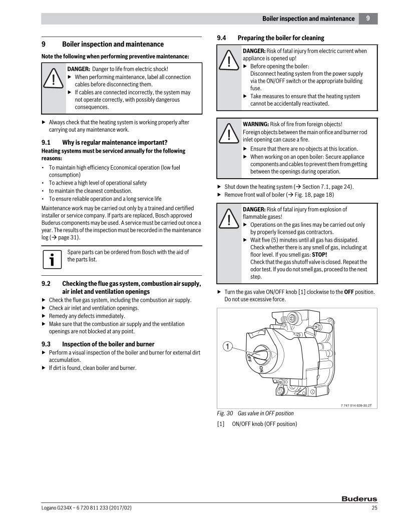
▶ Shut down the heating system ( Section 7.1, page 24).▶ Remove front wall of boiler ( Fig. 18, page 18)
▶ Turn the gas valve ON/OFF knob [1] clockwise to the OFF position. Do not use excessive force.
Fig. 30 Gas valve in OFF position
[1] ON/OFF knob (OFF position)
DANGER: Danger to life from electric shock!▶ When performing maintenance, label all connection
cables before disconnecting them.▶ If cables are connected incorrectly, the system may
not operate correctly, with possibly dangerous consequences.
Spare parts can be ordered from Bosch with the aid of the parts list.
DANGER: Risk of fatal injury from electric current when appliance is opened up!▶ Before opening the boiler:
Disconnect heating system from the power supply via the ON/OFF switch or the appropriate building fuse.
▶ Take measures to ensure that the heating system cannot be accidentally reactivated.
WARNING: Risk of fire from foreign objects!Foreign objects between the main orifice and burner rod inlet opening can cause a fire. ▶ Ensure that there are no objects at this location.▶ When working on an open boiler: Secure appliance
components and cables to prevent them from getting between the openings during operation.
DANGER: Risk of fatal injury from explosion of flammable gases!▶ Operations on the gas lines may be carried out only
by properly licensed gas contractors.▶ Wait five (5) minutes until all gas has dissipated.
Check whether there is any smell of gas, including at floor level. If you smell gas: STOP! Check that the gas shutoff valve is closed. Repeat the odor test. If you do not smell gas, proceed to the next step.
7 747 014 639-30.2T
1
Logano G234X – 6 720 811 233 (2017/02) 25

9 Boiler inspection and maintenance
9.5 Cleaning the boilerThe boiler can be cleaned with brushes and/or by wet cleaning. Cleaning equipment is available as an accessory by special order.
9.5.1 Remove burner:
▶ Disconnect the heating system from the power supply.▶ Close the gas main shutoff valve.▶ Disconnect pilot gas line [6] from the gas valve [8].▶ Disconnect high-tension ignition lead [3] from the burner controller.▶ Secure gas line [2] with wire or cord.▶ Loosen the union [1] on the gas supply line. ▶ Check the gasket for damage. Replace damaged gasket. Keep the
gasket in a safe place.▶ Identify the connection cable for the flame roll-out safety shutoff
switch [4] and then disconnect it from the flame roll-out safety shutoff switch [5].
▶ Disconnect connection lines to the gas valve [8].
Fig. 31 Removing the burner
[1] Union on gas supply line[2] Gas line[3] High-tension ignition lead[4] Flame roll-out switch connection cable[5] Flame roll-out safety shutoff switch[6] Pilot gas line[7] Connection cable to the gas valve[8] Gas valve
▶ Loosen retaining nuts ( Fig. 32 [1]) on the burner shield. ▶ Pull the burner out straight. ▶ Make sure that the spacers [2] remain on the studs.
Fig. 32 Removing the burner
[1] Retaining nuts[2] Studs with spacers
9.5.2 Cleaning the boiler with brushes (mechanical cleaning)▶ Remove the boiler casing and thermal insulation; check for damage.▶ Unscrew cleaning cover from the draft diverter.▶ Cover control unit with foil to prevent entry of metal dust into the
control unit. ▶ Use cleaning brushes [1] to brush out hot gas flues.▶ Clean combustion chamber and bottom panel.▶ Screw cleaning cover into place and replace insulation.▶ Install boiler cover.
Fig. 33 Cleaning the hot gas flues
[1] Cleaning brush[2] Thermal insulation
DANGER: Danger to life from electric shock!If cables are connected incorrectly, the system may not operate correctly, with possibly dangerous consequences.▶ When performing maintenance, label all connection
cables before disconnecting them.▶ Always check that the heating system is working
properly after carrying out any maintenance work.
DANGER: Risk of fatal injury from electric current when appliance is opened up!▶ Before opening the appliance:
Disconnect the heating system from the power supply completely via the ON/OFF switch or the appropriate building fuse.
▶ It is not sufficient just to switch off the controller.▶ Take measures to ensure that the heating system
cannot be accidentally reactivated.
6 720 806 028-12.1T
12
3
4
56
7
8
21
6 720 806 028-13.1T
6 720 806 028-21.1T
21
Logano G234X – 6 720 811 233 (2017/02)26

9 Boiler inspection and maintenance
9.5.3 Wet cleaning the boiler (chemical cleaning)▶ For wet cleaning, use a cleaning agent appropriate for the degree of
soiling (e. g. soot or scale).
▶ Remove the boiler casing and thermal insulation; check for damage.▶ Unscrew cleaning cover from the draft diverter.▶ Cover the control panel with foil to prevent spray getting into the
control panel.▶ Ventilate boiler room well.▶ Spray cleaning agent evenly from the top into the hot gas flues
( Fig. 34).▶ Install the burner in reverse order of removal ( Section 9.5.1).
Fig. 34 Wet cleaning the boiler
▶ Place the heating system in operation.▶ Heat the boiler to a temperature of at least 122 °F (55 °C).▶ Shut down the heating system.▶ Allow boiler to cool.▶ Remove burner ( Section 9.5.1).▶ Brush out the hot gas flues.▶ Clean combustion chamber and bottom panel.▶ Ventilate boiler room well again.▶ Install or clean the burner ( Section 9.6).▶ Screw cleaning cover into place and replace insulation.▶ Install boiler cover.
9.6 Cleaning the burner▶ Remove burner ( Section 9.5.1).▶ Check burner rods for dirt. If necessary, clean burner as described below:▶ Unscrew pilot burner unit ( Fig. 35 [1]) from burner.▶ Disconnect pilot gas line [3] from pilot burner unit.▶ Remove and blow out pilot orifice [2].▶ Immerse burner rods in water with cleaning agent and brush off.
Fig. 35 Pilot burner
[1] Pilot burner unit [2] Pilot orifice[3] Pilot gas line[4] Ignitor sensor cable▶ Rinse off the burner rods under a stream of water. Hold burner so that
water enters all slots of the burner rods and drains out again.▶ Remove remaining water by swinging the burner ( Fig. 36).
Fig. 36 Swinging burner
▶ Check that the burner rods are free. ▶ Remove water and dirt residue in the slots. ▶ If slots are damaged: Replace burner.▶ Install the burner in reverse order of removal ( Section 9.5.1).▶ Place boiler in operation as directed in Section 6, starting on
page 18.▶ Check that the AquaSmartTM functions properly.
In some circumstances, you may need to proceed differently from the method described here.▶ For wet cleaning (chemical cleaning), observe the
operating instructions of the relevant cleaning equipment and cleaning agent.
6 720 806 028-20.1T
▶ Make sure that the insulation on the burner shield does not get wet.
Logano G234X – 6 720 811 233 (2017/02) 27
9 Boiler inspection and maintenance
▶ If installed: Check low water indicator.▶ Check area around the boiler for potential hazards:
The area around the boiler must be free from flammable substances, gasoline or any other flammable or corrosive vapors and liquids.
▶ Complete the maintenance log to confirm that all maintenance work has been carried out ( page 31).
▶ Sign the maintenance log and familiarize the owner with how the heating system operates.
DANGER: Risk of fatal injury from explosion of flammable gases!Gas lines and their fittings may leak after maintenance has been performed. ▶ Carry out a proper leak test.▶ Only use approved leak detection agents.
Logano G234X – 6 720 811 233 (2017/02)28
9 Boiler inspection and maintenance
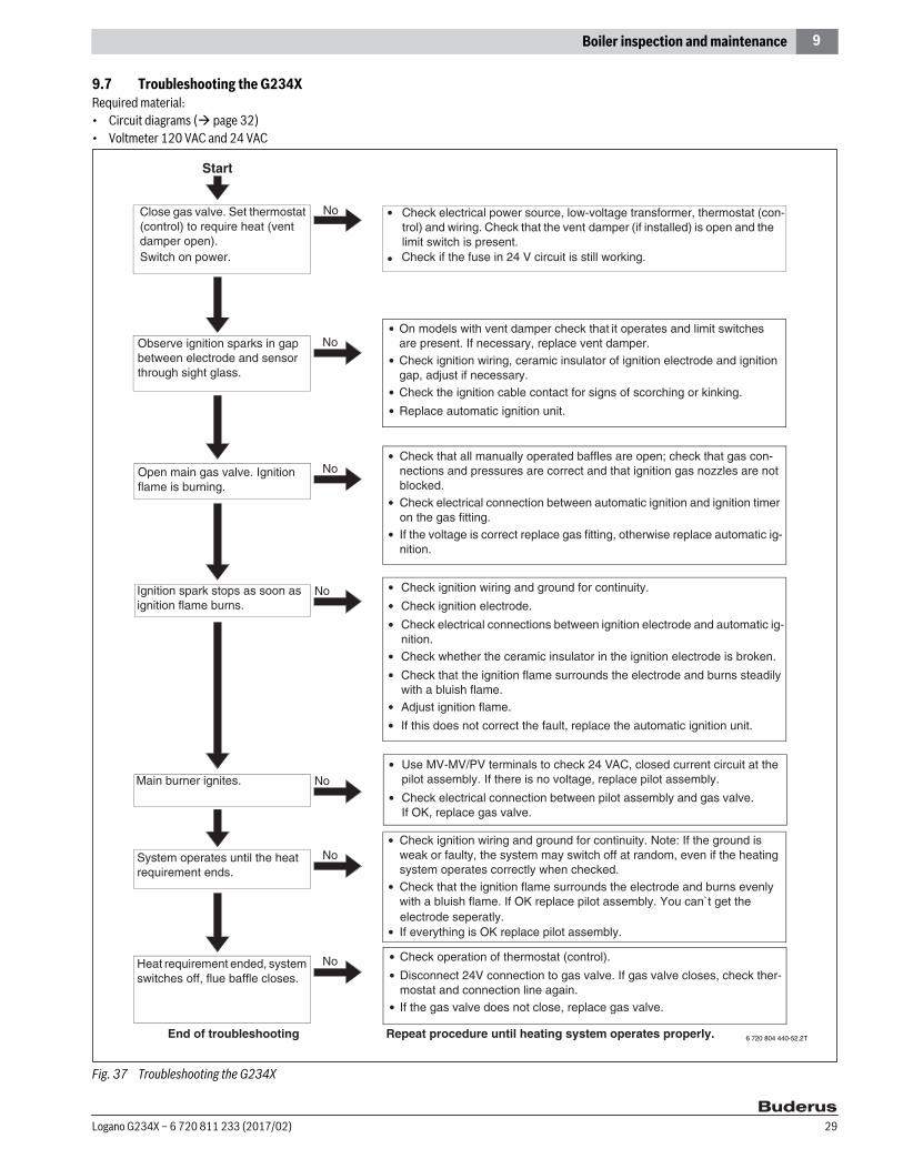
9.7 Troubleshooting the G234XRequired material:• Circuit diagrams ( page 32)• Voltmeter 120 VAC and 24 VAC
Fig. 37 Troubleshooting the G234X
Start
Close gas valve. Set thermostat (control) to require heat (vent damper open). Switch on power.
Observe ignition sparks in gap between electrode and sensor through sight glass.
• Check electrical power source, low-voltage transformer, thermostat (con-trol) and wiring. Check that the vent damper (if installed) is open and the limit switch is present.
No
No
NoOpen main gas valve. Ignition flame is burning.
• Check that all manually operated baffles are open; check that gas con-nections and pressures are correct and that ignition gas nozzles are not blocked.
• Check electrical connection between automatic ignition and ignition timer on the gas fitting.
• If the voltage is correct replace gas fitting, otherwise replace automatic ig-nition.
NoSystem operates until the heat requirement ends.
• Check ignition wiring and ground for continuity. Note: If the ground is weak or faulty, the system may switch off at random, even if the heating system operates correctly when checked.
• Check that the ignition flame surrounds the electrode and burns evenly with a bluish flame. If OK replace pilot assembly. You can`t get the
• If everything is OK replace pilot assembly.
NoHeat requirement ended, system switches off, flue baffle closes.
End of troubleshooting Repeat procedure until heating system operates properly.
• On models with vent damper check that it operates and limit switches are present. If necessary, replace vent damper.
• Check ignition wiring, ceramic insulator of ignition electrode and ignition gap, adjust if necessary.
• Check the ignition cable contact for signs of scorching or kinking.
• Replace automatic ignition unit.
NoIgnition spark stops as soon as ignition flame burns.
• Check ignition wiring and ground for continuity.
• Check ignition electrode.
• Check electrical connections between ignition electrode and automatic ig-nition.
• Check whether the ceramic insulator in the ignition electrode is broken.
• Check that the ignition flame surrounds the electrode and burns steadily with a bluish flame.
• Adjust ignition flame.
• If this does not correct the fault, replace the automatic ignition unit.
NoMain burner ignites.• Use MV-MV/PV terminals to check 24 V AC, closed current circuit at the
pilot assembly. If there is no voltage, replace pilot assembly.
• Check electrical connection between pilot assembly and gas valve. If OK, replace gas valve.
• Check operation of thermostat (control).
• Disconnect 24V connection to gas valve. If gas valve closes, check ther-mostat and connection line again.
• If the gas valve does not close, replace gas valve.
• Check if the fuse in 24 V circuit is still working.
electrode seperatly.
6 720 804 440-52.2T
Logano G234X – 6 720 811 233 (2017/02) 29
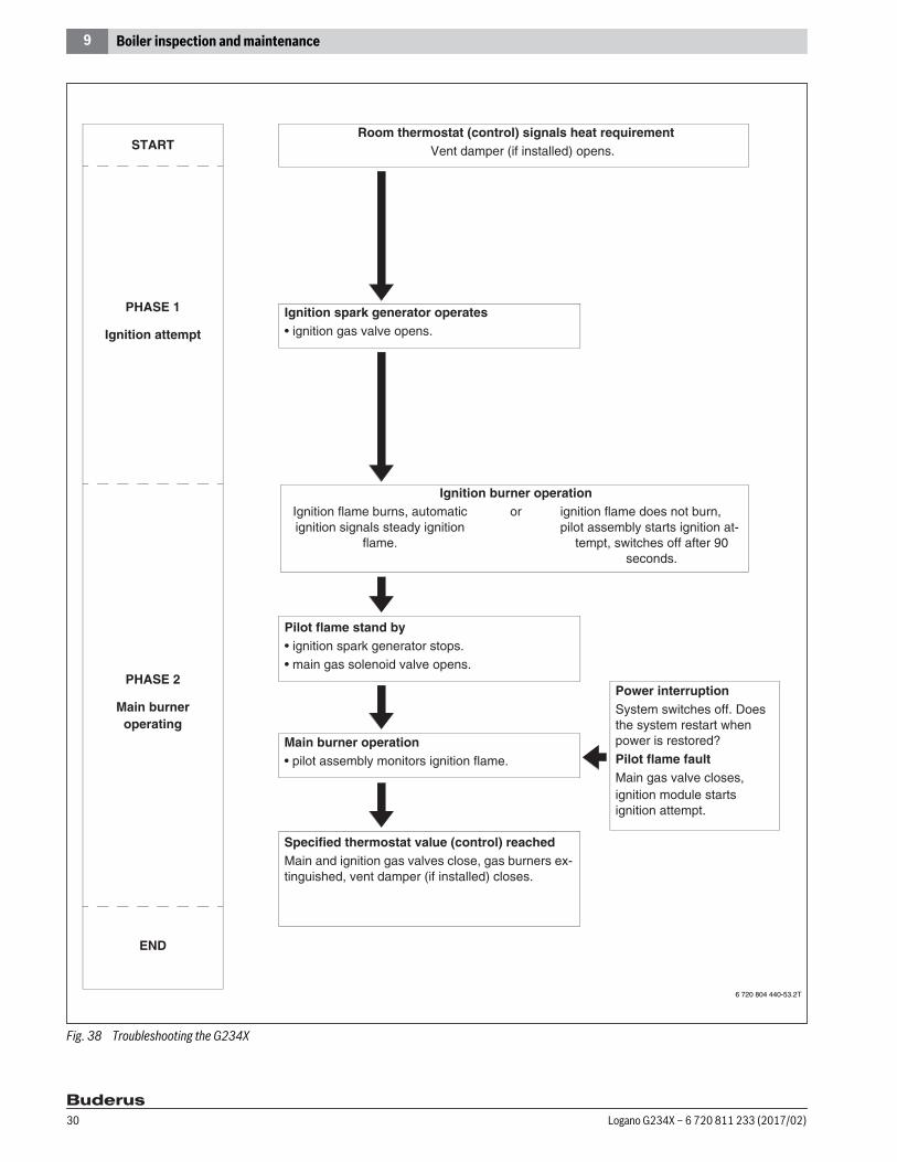
9 Boiler inspection and maintenance
Fig. 38 Troubleshooting the G234X
STARTRoom thermostat (control) signals heat requirement
Vent damper (if installed) opens.
Ignition spark generator operates• ignition gas valve opens.
Pilot flame stand by• ignition spark generator stops.• main gas solenoid valve opens.
Main burner operation• pilot assembly monitors ignition flame.
Specified thermostat value (control) reachedMain and ignition gas valves close, gas burners ex-tinguished, vent damper (if installed) closes.
Ignition burner operationIgnition flame burns, automatic ignition signals steady ignition
flame.
or ignition flame does not burn, pilot assembly starts ignition at-
tempt, switches off after 90 seconds.
END
PHASE 1
Ignition attempt
PHASE 2
Main burner operating
Power interruptionSystem switches off. Does the system restart when power is restored?
Pilot flame faultMain gas valve closes,ignition module starts ignition attempt.
6 720 804 440-53.2T
Logano G234X – 6 720 811 233 (2017/02)30
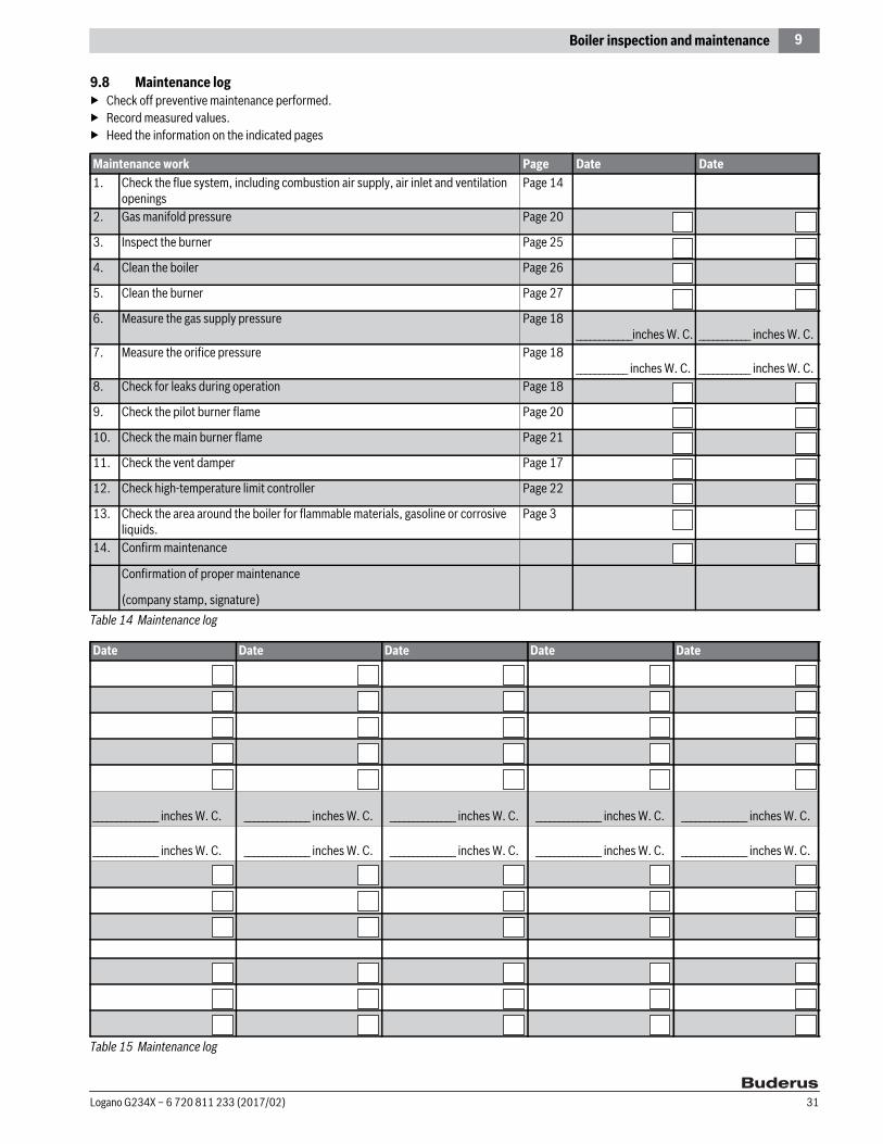
9 Boiler inspection and maintenance
9.8 Maintenance log▶ Check off preventive maintenance performed.▶ Record measured values.▶ Heed the information on the indicated pages
Maintenance work Page Date Date1. Check the flue system, including combustion air supply, air inlet and ventilation
openingsPage 14
2. Gas manifold pressure Page 20
3. Inspect the burner Page 25
4. Clean the boiler Page 26
5. Clean the burner Page 27
6. Measure the gas supply pressure Page 18____________inches W. C. ___________ inches W. C.
7. Measure the orifice pressure Page 18___________ inches W. C. ___________ inches W. C.
8. Check for leaks during operation Page 18
9. Check the pilot burner flame Page 20
10. Check the main burner flame Page 21
11. Check the vent damper Page 17
12. Check high-temperature limit controller Page 22
13. Check the area around the boiler for flammable materials, gasoline or corrosive liquids.
Page 3
14. Confirm maintenance
Confirmation of proper maintenance
(company stamp, signature)Table 14 Maintenance log
Date Date Date Date Date
______________ inches W. C. ______________ inches W. C. ______________ inches W. C. ______________ inches W. C. ______________ inches W. C.
______________ inches W. C. ______________ inches W. C. ______________ inches W. C. ______________ inches W. C. ______________ inches W. C.
Table 15 Maintenance log
Logano G234X – 6 720 811 233 (2017/02) 31

10 Electrical circuit diagrams
10 Electrical circuit diagrams
Fig. 39 Wiring diagram - G234X
US
Wirin
g diag
ram
gas-b
oiler
G23
4X U
SA-C
DNInt
ermi
ttent
pilot
8469
8718
5886
67
Plug
Plug
oran
ge
black
PV
white
blackwhite
black
Inter
mitte
nt pil
ot co
ntro
l mod
ule S
8600
H
2012/1
1
GAW
034
USA
Burn
er as
semb
ly
Term
inals
on b
oiler
bloc
k
Flam
e roll
out
safe
tysh
utoff
mea
ns
Bloc
ked
vent
switc
h
Inter
mitte
nt pil
ot du
alva
lve co
mbina
tion g
asco
ntrol
VR83
04
Pilot
bur
ner
(Hon
eywe
ll)
Main
valve
Pilot
valve
gree
n
blue
white
red
GND
MV
MV
PV
GND
PV
MV/P
VMV
24V
24V
43
21
Ref. n
o. :
Drwg
. no.:
Revie
wed :
Editio
n :
Wirin
g diag
ram :
Opt
iona
l Ven
tD
ampe
r Plu
g
RW
L2
Circ
ulato
r
NL
1
Emer
genc
ySh
ut-off
Swi
tch(b
y othe
rs)
L1C
1C
2ZC
ZRB
1B
2
2
Boile
r Sen
sor
Plug
3
Fuse
1,25
AT
24V
AWG
18
WIR
E
120
VAC
Conn
ectin
g te
rmina
ls fo
r the
rmos
tat
2
Main
supp
ly po
wer -
use
circ
uit b
reak
eras
requ
ired
by co
de1
Conn
ectin
g te
rmina
ls fo
r out
door
sens
or (o
ption
al)3
oran
ge
black
yello
w
6 720 804 886-06.2T
Logano G234X – 6 720 811 233 (2017/02)32

10 Electrical circuit diagrams
Fig. 40 Wiring diagram - G234X 6 720 804 886-07.2T
US
Bloc
ked
vent
swi
tch
B1 3
K1
WR T-St
at
C1L1 K2
M
Tran
sfor
mer
1 42
green
blue
white
red
Circ
ulato
rTo
Pilo
tBu
rner
Spar
k
Gas
valve
Main
Pilo
t PVPV M
V
GND
MV
S860
0HG
NDPV
PV/M
VM
V24
V
24VG
ND
K1
TR H
igh
Lim
it
Flam
e ro
ll out
safe
tysh
utof
f swi
tch
K2
B2
L2
NL
24V
AWG
18
WIR
E
120
VAC
Wiri
ng S
chem
atic
G23
4XCi
rcui
t bre
aker
Emer
genc
y sh
ut-o
ff sw
itch
C2
Fuse
1,25
AT
Wirin
g diag
ram
gas-b
oiler
G23
4X U
SA-C
DNInt
ermi
ttent
pilot
8469
8718
5886
67
2012/1
1
GAW
034
USA
Ref. n
o. :
Drwg
. no.:
Revie
wed :
Editio
n :
Wirin
g diag
ram :
Logano G234X – 6 720 811 233 (2017/02) 33

10
Notes
Logano G234X – 6 720 811 233 (2017/02)34

10
Notes
Logano G234X – 6 720 811 233 (2017/02) 35


![[XLS] · Web viewHeating boilers - Test code for heating boilers for atomizing oil burners Heating boilers - Part 2: Heating boilers with forced draught burners - Special requirements](https://img.pdfslide.net/doc/110x75/5aa92e707f8b9a72188c8d49/xls-viewheating-boilers-test-code-for-heating-boilers-for-atomizing-oil-burners.jpg)