Embed Size (px)
Citation preview
Gas Detector Array 2
User Guide
AIRSENSE Analytics GmbH Version 2
Airsense Analytics GmbH, Hagenower Strasse 73, D-19061 Schwerin 2
INTRODUCTION
The instrument Gas Detector Array is a battery operated analytical device designed to be used by the Fire Departments and other Safety forces in the detection and identification of Toxic Industrial Chemicals and Chemical Warfare Agents. The GDA Detector is based on a Hybrid Sensor Array Technology. By combinating the Ion Mobility Spectrometer, the Photo Ionization Detector, two Semiconductor sensors and an Electrochemical Cell in one handheld device the Gaseous Compounds are detected in the range of ppb to upper ppm level within seconds. If the characteristic sensor (array) response of certain compounds are stored in the GDA library the device will indicate it by its name. By changing the dilution either manually or automatically the measurement range of the sensors is extended. The GDA detects gaseous compounds in an expanded range of concentration. Furthermore the IMS and the other sensors are protected against overloading.
Warnings are shown as follows:
The first warning message tells the user that higher concentrations of certain compounds are present. When this warning appears no identification results are shown and also no concentration is given. Anyhow the user is alerted to the fact that there is something going on because one or more channels of the GDA are responding. By increasing the signals the user also may estimate the concentration. With the second warning message the user is informed of how high the concentration is. One of the channels responds to the limit. The alarm is released because there is a compound present in high concentration. The third warning message on the instrument panel display reports to the user the name of the compound and its concentration on the environment. With the Infrared Thermodesorber Tool installed in front of the GDA the instrument can be used for the evaluation of surfaces. This procedure can be determining by confirming, or not, the success of the decontamination process. The GDA can also be installed in surveillance vehicles in order to monitor the ambient air while driving.
Airsense Analytics GmbH, Hagenower Strasse 73, D-19061 Schwerin 3
INDEX
INTRODUCTION ................................................................................................................................................ 2
INDEX ............................................................................................................................................................... 3
GDA - TECHNICAL DATA ................................................................................................................................... 6
GDA 2 – GENERAL OVERVIEW .......................................................................................................................... 7
WARNINGS ....................................................................................................................................................... 9
GDA MEASUREMENT SEQUENCE .................................................................................................................... 12
SENSORS & SUBSTANCES ............................................................................................................................... 13
CHANNELS OF THE GDA .................................................................................................................................. 15
FLOW SYSTEM ................................................................................................................................................ 16
DILUTION PARAMETERS ................................................................................................................................... 16 How to choose the dilution factor?.............................................................................................................. 17
ALARM ........................................................................................................................................................... 18
Alarm Status & Options ............................................................................................................................... 18
LIBRARIES ....................................................................................................................................................... 19
How to Choose a Different Library? ............................................................................................................. 19
PASSWORD .................................................................................................................................................... 20
How to insert a Password on the device ...................................................................................................... 20
CLEANING MODE ............................................................................................................................................ 21
BASELINE ACQUIREMENT ............................................................................................................................... 21
THE ZERO POINT PROCESS ! ..................................................................................................................................... 21 What is so important about the Baseline Acquirement? ............................................................................. 21
SUBSTANCE WITH QUESTION MARK (?) ......................................................................................................... 22
A question mark “?” may appear after the name of a substance, for example, “HCN ?”. .......................... 22
GDA MODE OVERVIEW .................................................................................................................................. 23
LAUNCHING THE DEVICE ................................................................................................................................ 24
QUICK START: ................................................................................................................................................. 24
LAUNCHING THE BASELINE ACQUIREMENT...................................................................................................... 26
LAUNCHING THE GDA MODE: ......................................................................................................................... 27
AIR MONITORING MODE ................................................................................................................................ 28
LAUNCHING THE AIR MONITORING MODE ................................................................................................. 28
SOURCE MONITORING MODE ........................................................................................................................ 29
LAUNCHING THE SOURCE MONITORING MODE.......................................................................................... 29
EXAMPLE SITUATION: .................................................................................................................................... 30
PHOTO IONIZATION DETECTOR ...................................................................................................................... 31
PID MODE .......................................................................................................................................................... 31 LAUNCHING THE PID MODE ........................................................................................................................ 31
www.airsense.com 4
How to CHOOSE the target substance!........................................................................................................ 32 How to Exit from the PID Mode ................................................................................................................... 33
SUBSTANCE IDENTIFICATION ON AMMONIA CHEMISTRY SET UP................................................................... 34
DETECTION OF CHEMICAL WARFARE AGENTS ............................................................................................................. 34
AMMONIA CHEMISTRY - GDA SET UP............................................................................................................. 35
HOW TO INSERT THE AMMONIA SOURCE ................................................................................................... 35
DEVICE DECONTAMINATION .......................................................................................................................... 37
SCM TOOL - ANALYSING DECONTAMINATED SURFACES ................................................................................ 39
Connecting the SCM Tool ............................................................................................................................. 39
CLEAN UP PROCEDURE ................................................................................................................................... 41
SWITCHING OFF THE GDA .............................................................................................................................. 42
EXTERNAL FILTER UNIT ................................................................................................................................... 43
Connecting the GDA to the External Filter Unit ........................................................................................... 43 Starting: ....................................................................................................................................................... 43
NON AUTONOMOUS USE ............................................................................................................................... 44
MEASURING WITH WINMUSTER .................................................................................................................... 44
Installing WinMuster ................................................................................................................................... 44
STARTING WINMUSTER .................................................................................................................................. 45
SYMBOLS AND FUNCTIONS: ..................................................................................................................................... 45 DEVICE CONTROL PANEL ......................................................................................................................................... 46 SYMBOLS ............................................................................................................................................................. 46 WINMUSTER VIEWING TOOLS ................................................................................................................................. 47 WINMUSTER & LIBRARIES ................................................................................................................................... 48
DOWNLOAD NEW LIBRARIES ....................................................................................................................... 48 UPLOADING A LIBRARY FROM THE FILE: ..................................................................................................................... 48
Uploading a library from the GDA: .............................................................................................................. 49 Saving a Library to a File .............................................................................................................................. 49
PERFORM MEASUREMENTS WITH THE SOFTWARE ........................................................................................ 50
DATA LOGGER: ............................................................................................................................................... 52
Reading the Data Logger from the GDA ...................................................................................................... 53 Erasing the Data Logger through the Software ........................................................................................... 53 Erasing the data logger through the GDA ................................................................................................... 55
GDA’S APPLICATION ....................................................................................................................................... 56
ON A SURVEILLANCE VEHICLE ........................................................................................................................ 56
AIR MONITORING inside a Surveillance Vehicle........................................................................................... 56
GDA OPTIONAL FEATURES ............................................................................................................................. 57
WIRELESS ANTENNA ....................................................................................................................................... 57
GPS ANTENNA ................................................................................................................................................ 60
How does it work? ....................................................................................................................................... 60 Preparing the GPS information .................................................................................................................... 60
GDA MAINTENANCE ....................................................................................................................................... 61
SYSTEM CHECK ............................................................................................................................................... 62
FLOW CHECK .................................................................................................................................................. 62
www.airsense.com 5
Launching the FLOW CHECK tool ................................................................................................................. 63
SENSOR CHECK ............................................................................................................................................... 65
PEAK HEIGHT .................................................................................................................................................. 66
PEAK HEIGHT: INTERPRETING THE INSTRUMENT ........................................................................................... 67
REPLACING THE ELECTROCHEMICAL CELL ........................................................................................................ 68 FILTERS ............................................................................................................................................................. 69 REPLACING THE FILTERS ................................................................................................................................... 70 RESET THE INTERNAL COUNTER CLOCK ....................................................................................................................... 71 REPLACING THE O RINGS .................................................................................................................................. 72 HOW TO CLEAN THE PID LAMP ......................................................................................................................... 73
LAMP ........................................................................................................................................................... 73 PID CALIBRATION .............................................................................................................................................. 74 TESTING THE PID ............................................................................................................................................... 75
APPENDIX ....................................................................................................................................................... 77
DECLARATION OF CONTAMINATION .......................................................................................................................... 78 DECLARATION OF CONTAMINATION FORMULARY ......................................................................................................... 79 IDENTIFICATION TABLE ........................................................................................................................................... 80 CHANNELS OF THE GDA 2....................................................................................................................................... 81 STRUCTURE OF THE MENU ............................................................................................................................... 82 ERROR MESSAGES ................................................................................................................................................. 83 IMS ONLY MODE’S SYMBOLS ............................................................................................................................ 85
ALPHABETICAL INDEX ..................................................................................................................................... 86
www.airsense.com 6
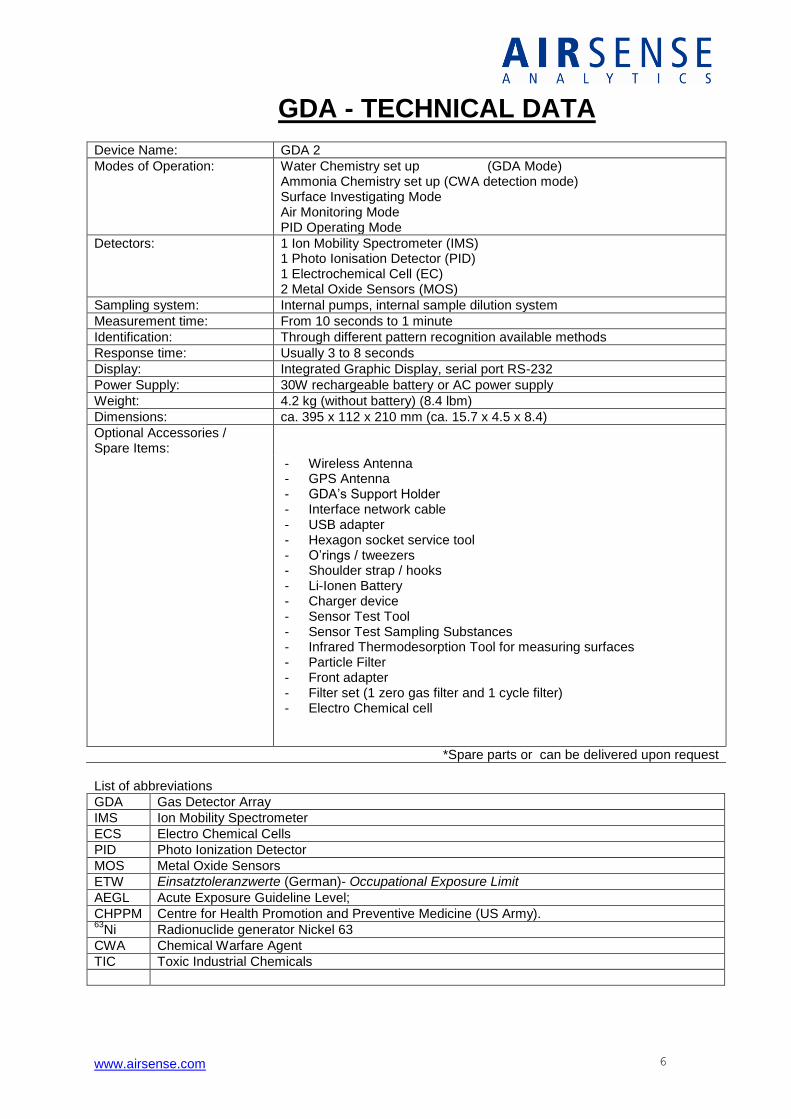
GDA - TECHNICAL DATA Device Name: GDA 2
Modes of Operation: Water Chemistry set up (GDA Mode) Ammonia Chemistry set up (CWA detection mode) Surface Investigating Mode Air Monitoring Mode PID Operating Mode
Detectors: 1 Ion Mobility Spectrometer (IMS) 1 Photo Ionisation Detector (PID) 1 Electrochemical Cell (EC) 2 Metal Oxide Sensors (MOS)
Sampling system: Internal pumps, internal sample dilution system
Measurement time: From 10 seconds to 1 minute
Identification: Through different pattern recognition available methods
Response time: Usually 3 to 8 seconds
Display: Integrated Graphic Display, serial port RS-232
Power Supply: 30W rechargeable battery or AC power supply
Weight: 4.2 kg (without battery) (8.4 lbm)
Dimensions: ca. 395 x 112 x 210 mm (ca. 15.7 x 4.5 x 8.4)
Optional Accessories / Spare Items:
- Wireless Antenna - GPS Antenna - GDA’s Support Holder - Interface network cable - USB adapter - Hexagon socket service tool - O’rings / tweezers - Shoulder strap / hooks - Li-Ionen Battery - Charger device - Sensor Test Tool - Sensor Test Sampling Substances - Infrared Thermodesorption Tool for measuring surfaces - Particle Filter - Front adapter - Filter set (1 zero gas filter and 1 cycle filter) - Electro Chemical cell
*Spare parts or can be delivered upon request
List of abbreviations
GDA Gas Detector Array
IMS Ion Mobility Spectrometer
ECS Electro Chemical Cells
PID Photo Ionization Detector
MOS Metal Oxide Sensors
ETW Einsatztoleranzwerte (German)- Occupational Exposure Limit
AEGL Acute Exposure Guideline Level;
CHPPM Centre for Health Promotion and Preventive Medicine (US Army). 63
Ni Radionuclide generator Nickel 63
CWA Chemical Warfare Agent
TIC Toxic Industrial Chemicals
www.airsense.com 7
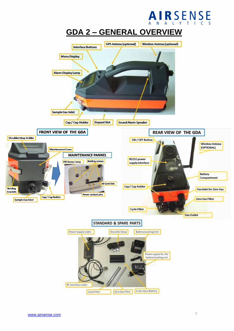
GDA 2 – GENERAL OVERVIEW
www.airsense.com 8
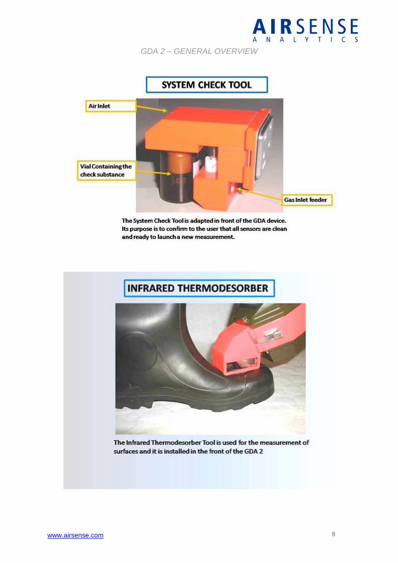
GDA 2 – GENERAL OVERVIEW
www.airsense.com 9
WARNINGS
The GDA2 is an analytical measurement device. Avoid extreme temperatures and concussions.
Use the instrument only for the specified applications and avoid high concentrations especially by organic compounds.
Most of the samples can be toxic !
Protect all inlets, outlets and check substances for pollutions otherwise the instrument will not work properly.
Never suck in liquids or fire smoke in the gas inlet because the system may be destroyed.
Spare parts should be kept in its original packaging until its use.
www.airsense.com 10
WARNINGS
The disposal of the batteries must be done according the national and international rules.
It is not allowed to open the device during the use because injuries may occur caused by High voltage and UV radiation.
The device contains radioactive compounds. Radioactive sources are marked by a safety label. Do not remove or destroy the safety labels.
www.airsense.com 11
WARNINGS
Defects: In case of defect, all devices containing radioactive sources that have defects must return to the manufacturer. These parts must be packed in the original transportation case.
If one device was damaged, destroyed or the radioactive source was damaged the instrument must return to the manufacturer inside the metal case containing the declaration of Contamination.
Be extremely careful if the filters are contaminated by Chemical Warfare Agents!
Use protection clothing and mark the contaminated material immediately.
Fill in completely the declaration of Contamination in case the instruments or spare parts have to be sent back to the manufacturer. This declaration must be sent together with the instrument !
www.airsense.com 12
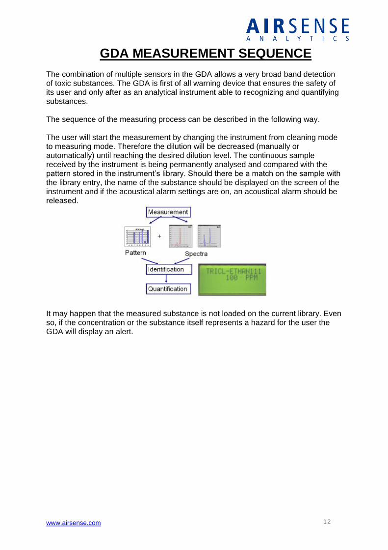
GDA MEASUREMENT SEQUENCE The combination of multiple sensors in the GDA allows a very broad band detection of toxic substances. The GDA is first of all warning device that ensures the safety of its user and only after as an analytical instrument able to recognizing and quantifying substances. The sequence of the measuring process can be described in the following way. The user will start the measurement by changing the instrument from cleaning mode to measuring mode. Therefore the dilution will be decreased (manually or automatically) until reaching the desired dilution level. The continuous sample received by the instrument is being permanently analysed and compared with the pattern stored in the instrument’s library. Should there be a match on the sample with the library entry, the name of the substance should be displayed on the screen of the instrument and if the acoustical alarm settings are on, an acoustical alarm should be released.
It may happen that the measured substance is not loaded on the current library. Even so, if the concentration or the substance itself represents a hazard for the user the GDA will display an alert.
www.airsense.com 13
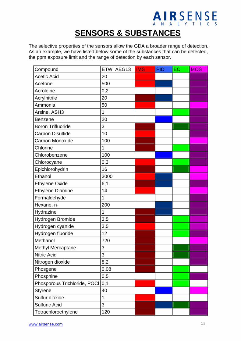
SENSORS & SUBSTANCES The selective properties of the sensors allow the GDA a broader range of detection. As an example, we have listed below some of the substances that can be detected, the ppm exposure limit and the range of detection by each sensor.
Compound ETW AEGL3 IMS PID EC MOS
Acetic Acid 20
Acetone 500
Acroleine 0,2
Acrylnitrile 20
Ammonia 50
Arsine, ASH3 1
Benzene 20
Boron Trifluoride 3
Carbon Disulfide 10
Carbon Monoxide 100
Chlorine 1
Chlorobenzene 100
Chlorocyane 0,3
Epichlorohydrin 16
Ethanol 3000
Ethylene Oxide 6,1
Ethylene Diamine 14
Formaldehyde 1
Hexane, n- 200
Hydrazine 1
Hydrogen Bromide 3,5
Hydrogen cyanide 3,5
Hydrogen fluoride 12
Methanol 720
Methyl Mercaptane 3
Nitric Acid 3
Nitrogen dioxide 8,2
Phosgene 0,08
Phosphine 0,5
Phosporous Trichloride, POCl 0,1
Styrene 40
Sulfur dioxide 1
Sulfuric Acid 3
Tetrachloroethylene 120
www.airsense.com 14
Toluene 94
Toluene diisocyanate, TDI 0,02
Trichloro methane 90
Trichloroethane, 1,1,1- 380
Trichloroethane, 1,1,2- 25
Trichloroethylene 100
Vinyl chloride 100
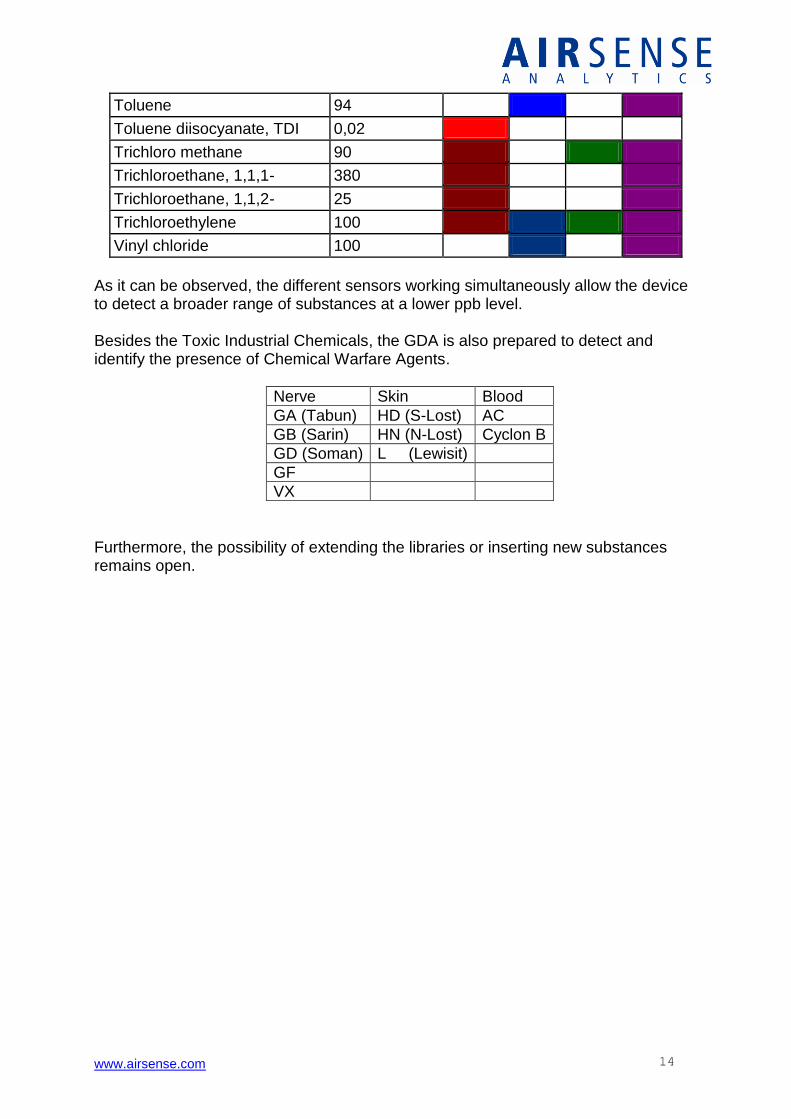
As it can be observed, the different sensors working simultaneously allow the device to detect a broader range of substances at a lower ppb level. Besides the Toxic Industrial Chemicals, the GDA is also prepared to detect and identify the presence of Chemical Warfare Agents.
Nerve Skin Blood
GA (Tabun) HD (S-Lost) AC
GB (Sarin) HN (N-Lost) Cyclon B
GD (Soman) L (Lewisit)
GF
VX
Furthermore, the possibility of extending the libraries or inserting new substances remains open.
www.airsense.com 15
CHANNELS OF THE GDA
From Sensors to the Channels
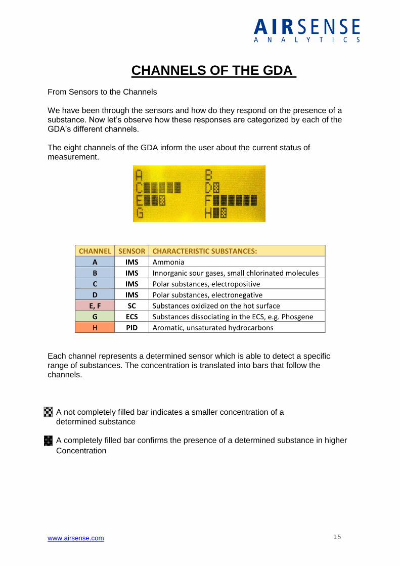
We have been through the sensors and how do they respond on the presence of a substance. Now let’s observe how these responses are categorized by each of the GDA’s different channels. The eight channels of the GDA inform the user about the current status of measurement.
CHANNEL SENSOR CHARACTERISTIC SUBSTANCES:
A IMS Ammonia
B IMS Innorganic sour gases, small chlorinated molecules
C IMS Polar substances, electropositive
D IMS Polar substances, electronegative
E, F SC Substances oxidized on the hot surface
G ECS Substances dissociating in the ECS, e.g. Phosgene
H PID Aromatic, unsaturated hydrocarbons Each channel represents a determined sensor which is able to detect a specific range of substances. The concentration is translated into bars that follow the channels.
A not completely filled bar indicates a smaller concentration of a determined substance
A completely filled bar confirms the presence of a determined substance in higher
Concentration
www.airsense.com 16
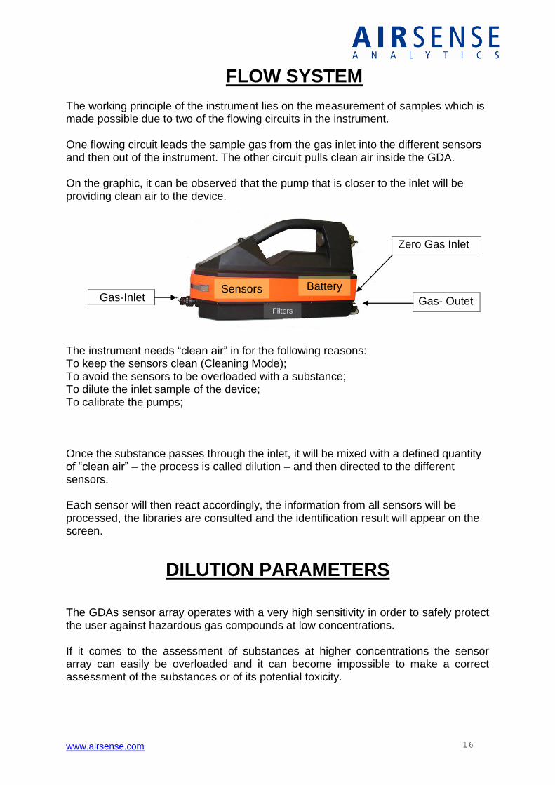
FLOW SYSTEM The working principle of the instrument lies on the measurement of samples which is made possible due to two of the flowing circuits in the instrument. One flowing circuit leads the sample gas from the gas inlet into the different sensors and then out of the instrument. The other circuit pulls clean air inside the GDA. On the graphic, it can be observed that the pump that is closer to the inlet will be providing clean air to the device.
The instrument needs “clean air” in for the following reasons: To keep the sensors clean (Cleaning Mode); To avoid the sensors to be overloaded with a substance; To dilute the inlet sample of the device; To calibrate the pumps; Once the substance passes through the inlet, it will be mixed with a defined quantity of “clean air” – the process is called dilution – and then directed to the different sensors. Each sensor will then react accordingly, the information from all sensors will be processed, the libraries are consulted and the identification result will appear on the screen.
DILUTION PARAMETERS
The GDAs sensor array operates with a very high sensitivity in order to safely protect the user against hazardous gas compounds at low concentrations. If it comes to the assessment of substances at higher concentrations the sensor array can easily be overloaded and it can become impossible to make a correct assessment of the substances or of its potential toxicity.
Sensors Gas-Inlet Gas- Outet
Zero Gas Inlet
Battery
Filters
www.airsense.com 17
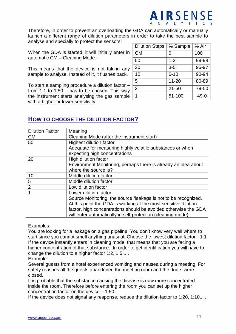
Therefore, in order to prevent an overloading the GDA can automatically or manually launch a different range of dilution parameters in order to take the best sample to analyse and specially to protect the sensors! When the GDA is started, it will initially enter in automatic CM – Cleaning Mode. This means that the device is not taking any sample to analyse. Instead of it, it flushes back. To start a sampling procedure a dilution factor – from 1:1 to 1:50 – has to be chosen. This way the instrument starts analysing the gas sample with a higher or lower sensitivity.
HOW TO CHOOSE THE DILUTION FACTOR?
Dilution Factor Meaning
CM Cleaning Mode (after the instrument start)
50 Highest dilution factor Adequate for measuring highly volatile substances or when expecting high concentrations
20 High dilution factor Environment Monitoring, perhaps there is already an idea about where the source is?
10 Middle dilution factor
5 Middle dilution factor
2 Low dilution factor
1 Lower dilution factor Source Monitoring, the source /leakage is not to be recognized. At this point the GDA is working at the most sensitive dilution factor, high concentrations should be avoided otherwise the GDA will enter automatically in self-protection (cleaning mode).
Examples: You are looking for a leakage on a gas pipeline. You don’t know very well where to start since you cannot smell anything unusual. Choose the lowest dilution factor - 1:1. If the device instantly enters in cleaning mode, that means that you are facing a higher concentration of that substance. In order to get identification you will have to change the dilution to a higher factor 1:2, 1:5... . Example: Several guests from a hotel experienced vomiting and nausea during a meeting. For safety reasons all the guests abandoned the meeting room and the doors were closed. It is probable that the substance causing the disease is now more concentrated inside the room. Therefore before entering the room you can set up the higher concentration factor on the device – 1:50. If the device does not signal any response, reduce the dilution factor to 1:20, 1:10... .
Dilution Steps % Sample % Air
CM 0 100
50 1-2 99-98
20 3-5 95-97
10 6-10 90-94
5 11-20 80-89
2 21-50 79-50
1 51-100 49-0
www.airsense.com 18
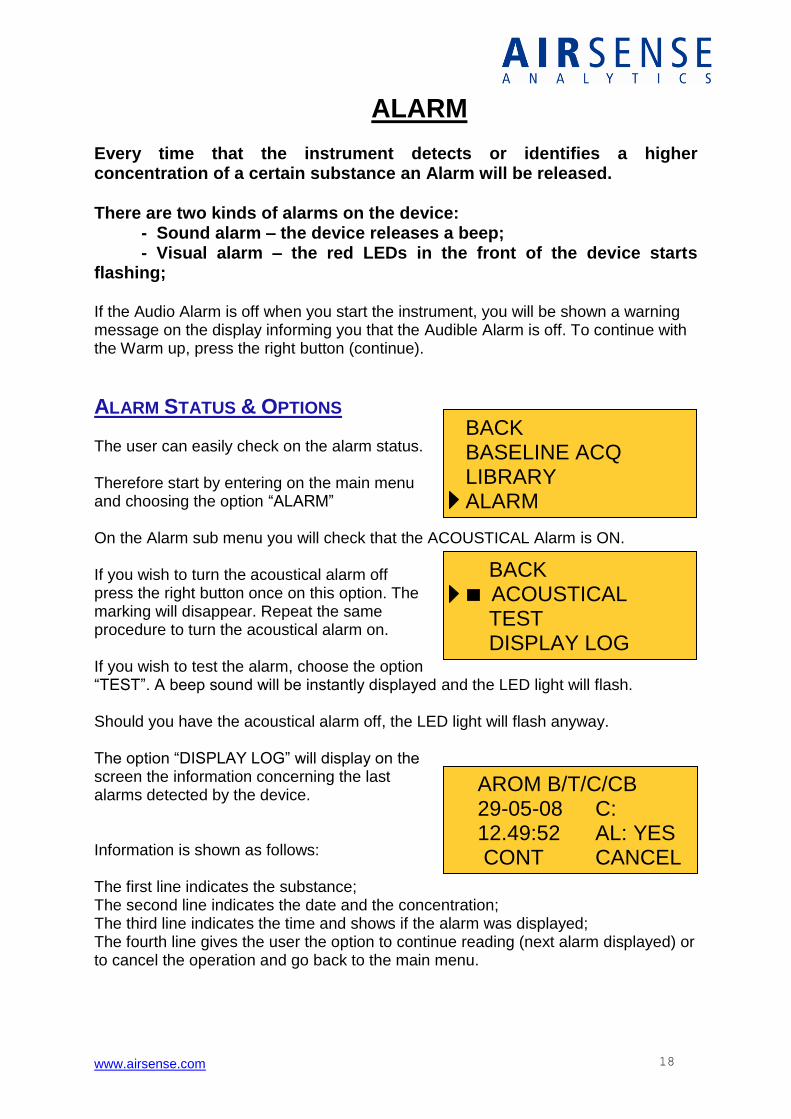
AROM B/T/C/CB 29-05-08 C: 12.49:52 AL: YES CONT CANCEL
BACK ACOUSTICAL TEST DISPLAY LOG
BACK BASELINE ACQ LIBRARY ALARM
ALARM Every time that the instrument detects or identifies a higher concentration of a certain substance an Alarm will be released. There are two kinds of alarms on the device: - Sound alarm – the device releases a beep; - Visual alarm – the red LEDs in the front of the device starts flashing; If the Audio Alarm is off when you start the instrument, you will be shown a warning message on the display informing you that the Audible Alarm is off. To continue with the Warm up, press the right button (continue).
ALARM STATUS & OPTIONS The user can easily check on the alarm status. Therefore start by entering on the main menu and choosing the option “ALARM” On the Alarm sub menu you will check that the ACOUSTICAL Alarm is ON. If you wish to turn the acoustical alarm off press the right button once on this option. The marking will disappear. Repeat the same procedure to turn the acoustical alarm on. If you wish to test the alarm, choose the option “TEST”. A beep sound will be instantly displayed and the LED light will flash. Should you have the acoustical alarm off, the LED light will flash anyway. The option “DISPLAY LOG” will display on the screen the information concerning the last alarms detected by the device. Information is shown as follows: The first line indicates the substance; The second line indicates the date and the concentration; The third line indicates the time and shows if the alarm was displayed; The fourth line gives the user the option to continue reading (next alarm displayed) or to cancel the operation and go back to the main menu.
www.airsense.com 19
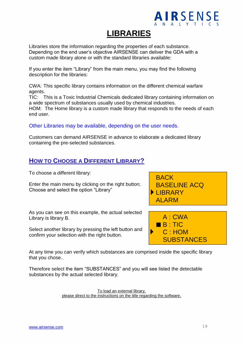
A : CWA B : TIC C : HOM SUBSTANCES
LIBRARIES Libraries store the information regarding the properties of each substance. Depending on the end user’s objective AIRSENSE can deliver the GDA with a custom made library alone or with the standard libraries available: If you enter the item “Library” from the main menu, you may find the following description for the libraries: CWA: This specific library contains information on the different chemical warfare agents. TIC: This is a Toxic Industrial Chemicals dedicated library containing information on a wide spectrum of substances usually used by chemical industries. HOM: The Home library is a custom made library that responds to the needs of each end user.
Other Libraries may be available, depending on the user needs. Customers can demand AIRSENSE in advance to elaborate a dedicated library containing the pre-selected substances.
HOW TO CHOOSE A DIFFERENT LIBRARY? To choose a different library: Enter the main menu by clicking on the right button; Choose and select the option “Library” As you can see on this example, the actual selected Library is library B. Select another library by pressing the left button and confirm your selection with the right button. At any time you can verify which substances are comprised inside the specific library that you chose.. Therefore select the item “SUBSTANCES” and you will see listed the detectable substances by the actual selected library.
To load an external library, please direct to the instructions on the title regarding the software.
BACK BASELINE ACQ LIBRARY ALARM
www.airsense.com 20
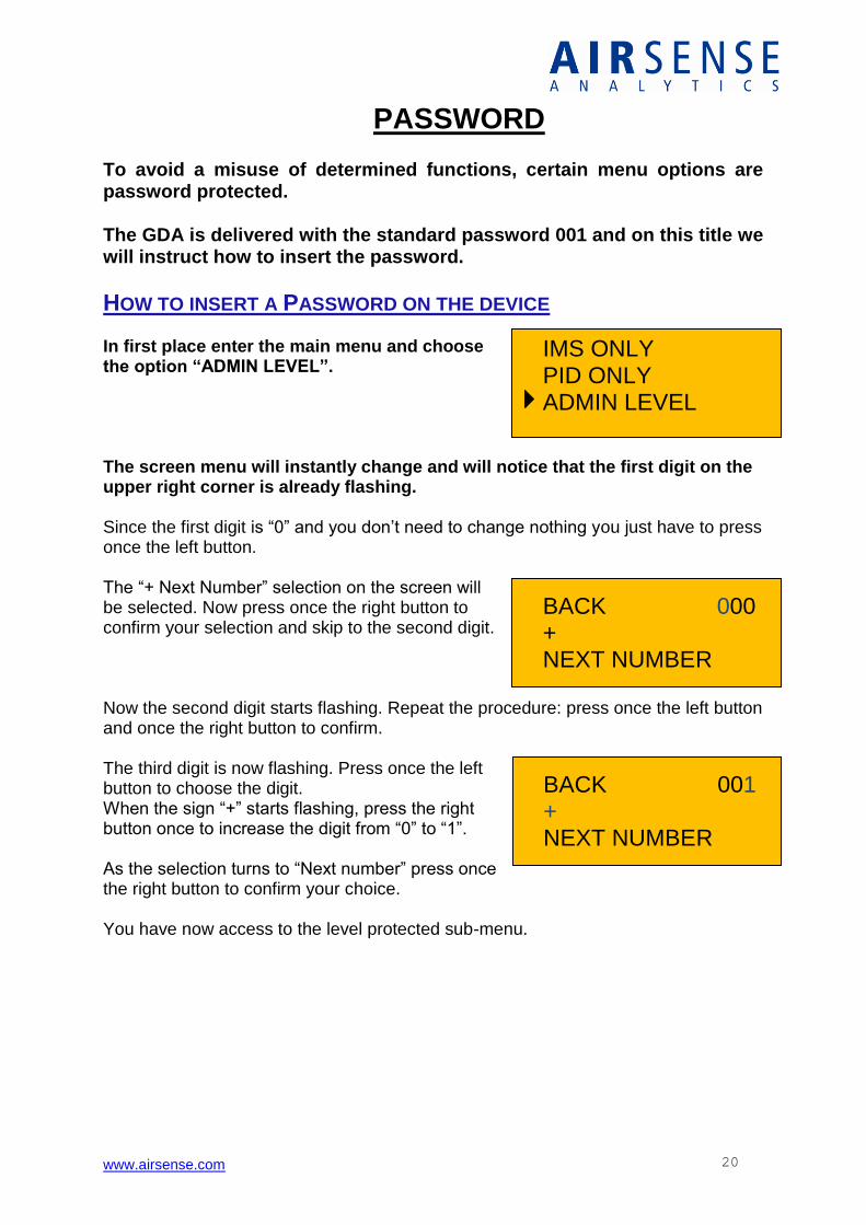
IMS ONLY PID ONLY ADMIN LEVEL
BACK 000 + NEXT NUMBER
BACK 001 + NEXT NUMBER
PASSWORD To avoid a misuse of determined functions, certain menu options are password protected. The GDA is delivered with the standard password 001 and on this title we will instruct how to insert the password.
HOW TO INSERT A PASSWORD ON THE DEVICE In first place enter the main menu and choose the option “ADMIN LEVEL”. The screen menu will instantly change and will notice that the first digit on the upper right corner is already flashing. Since the first digit is “0” and you don’t need to change nothing you just have to press once the left button. The “+ Next Number” selection on the screen will be selected. Now press once the right button to confirm your selection and skip to the second digit. Now the second digit starts flashing. Repeat the procedure: press once the left button and once the right button to confirm. The third digit is now flashing. Press once the left button to choose the digit. When the sign “+” starts flashing, press the right button once to increase the digit from “0” to “1”. As the selection turns to “Next number” press once the right button to confirm your choice. You have now access to the level protected sub-menu.
www.airsense.com 21
CLEANING MODE The CLEANING MODE is an automatic self-protection working function that is automatically launched each time that one of the eight channels responds to the maximum on a determined substance. This operation can last some seconds until the concentration level of that substance decreases to accepted values. Unlike other operating modes you will not need to use any library on the cleaning mode since this is a self-protection mode. If there is enough time before launching a measurement, it is recommended to run the device in cleaning mode for about 5 to 10 minutes. It is also recommended to run the device in Cleaning Mode for an equal period after each measurement until the channels do not detect any signals any more. The objective is to be sure that the channels are clean before starting a new measurement or connecting the device to an external filtering unit.
BASELINE ACQUIREMENT
The zero point process !
WHAT IS SO IMPORTANT ABOUT THE BASELINE ACQUIREMENT? If remnant compounds are left in the analytical system, these may cause a slight offset of the measurement. This situation will reveal signals which may in certain occasions disturb the ongoing identification. Therefore, the baseline acquirement process will reset and balance the different channels (sensors) of the GDA device. It is recommended to do the baseline acquirement, when the instrument had enough time to clean up after the last measurement when the signals of the channels do not vary significantly In order to act safe, we recommend doing the Baseline Acquirement each time before performing an important measurement. Depending on the conditions, it takes about one minute to be completed.
For practical information, see the Title „Launching the Baseline Acquirement”.
www.airsense.com 22
SUBSTANCE WITH QUESTION MARK (?)
A QUESTION MARK “?” MAY APPEAR AFTER THE NAME OF A
SUBSTANCE, FOR EXAMPLE, “HCN ?”. The display of the GDA has shown a question mark after the name of detected substance, “HCN?” 1 – One cause can be that when working in open air, the GDA recognises the presence of HCN but other components in very lower concentrations are also present. These substances cannot be directly identified but they are detected. If that is the case, to evaluate which substances can these be, the user should analyse the spectra and look at the response of the different channels. Since each channel responds to a different sensor and reports to a different substance group there is a greater possibility of finding a matching pattern and deduct which other compounds are present. 2 - The question mark may also appear if the user interrupts the identification process before the device completes the identification process. In that case, the user can decide if it is necessary to make a new assessment. 3- If there is a very high concentration of a substance the device can enter in cleaning mode (self-protection) automatically. In this case the identification time was adequate to identify the substance but it wasn’t enough to quantify the substance; Should it be the case, the user can launch a new measurement.
www.airsense.com 23
GDA MODE OVERVIEW
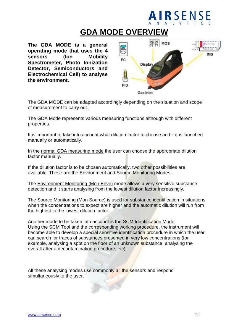
The GDA MODE is a general operating mode that uses the 4 sensors (Ion Mobility Spectrometer, Photo Ionization Detector, Semiconductors and Electrochemical Cell) to analyse the environment. The GDA MODE can be adapted accordingly depending on the situation and scope of measurement to carry out. The GDA Mode represents various measuring functions although with different properties. It is important to take into account what dilution factor to choose and if it is launched manually or automatically. In the normal GDA measuring mode the user can choose the appropriate dilution factor manually. If the dilution factor is to be chosen automatically, two other possibilities are available. These are the Environment and Source Monitoring Modes. The Environment Monitoring (Mon Envir) mode allows a very sensitive substance detection and it starts analysing from the lowest dilution factor increasingly. The Source Monitoring (Mon Source) is used for substance identification in situations when the concentrations to expect are higher and the automatic dilution will run from the highest to the lowest dilution factor. Another mode to be taken into account is the SCM Identification Mode. Using the SCM Tool and the corresponding working procedure, the instrument will become able to develop a special sensitive identification procedure in which the user can search for traces of substances presented in very low concentrations (for example, analysing a spot on the floor of an unknown substance; analysing the overall after a decontamination procedure, etc). All these analysing modes use commonly all the sensors and respond simultaneously to the user.
www.airsense.com 24
GDA II AIRSENSE ANALYTICS
LAUNCHING THE DEVICE
Over the next titles the user will learn how to make use of the GDA and its multiple purpose functions under the Water Chemistry set up application.
QUICK START:
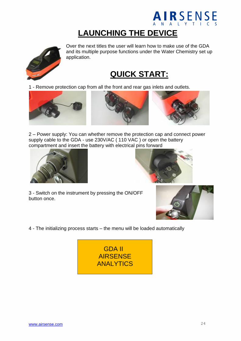
1 - Remove protection cap from all the front and rear gas inlets and outlets.
2 – Power supply: You can whether remove the protection cap and connect power supply cable to the GDA - use 230V/AC ( 110 VAC ) or open the battery compartment and insert the battery with electrical pins forward
3 - Switch on the instrument by pressing the ON/OFF button once.
4 - The initializing process starts – the menu will be loaded automatically
www.airsense.com 25
REMOVE CAPS
CONTINUE
RI KO LEVEL POS: 2.10 164 NEG: 2.22 695
CONTINUE
LAUNCHING
MEASUREMENT
CLEANING MODE
A X C M
WARM UP
MB: 49.7 DR:35.5
CONTINUE
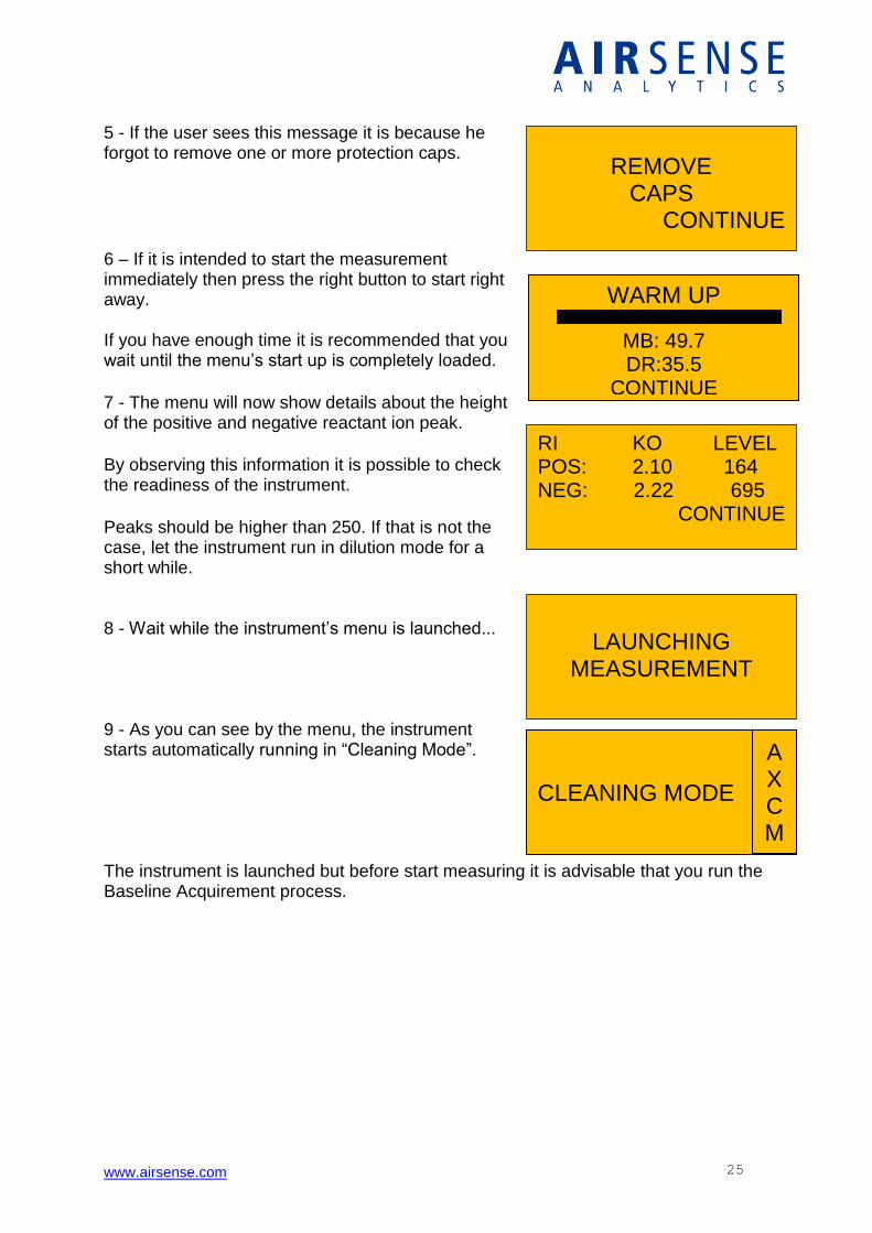
5 - If the user sees this message it is because he forgot to remove one or more protection caps.
6 – If it is intended to start the measurement immediately then press the right button to start right away. If you have enough time it is recommended that you wait until the menu’s start up is completely loaded.
7 - The menu will now show details about the height of the positive and negative reactant ion peak.
By observing this information it is possible to check the readiness of the instrument.
Peaks should be higher than 250. If that is not the case, let the instrument run in dilution mode for a short while. 8 - Wait while the instrument’s menu is launched... 9 - As you can see by the menu, the instrument starts automatically running in “Cleaning Mode”. The instrument is launched but before start measuring it is advisable that you run the Baseline Acquirement process.
www.airsense.com 26
BASELINE WILL BE
ACCOMPLISHED
BACK BASELINE ACQ LIBRARY ALARM
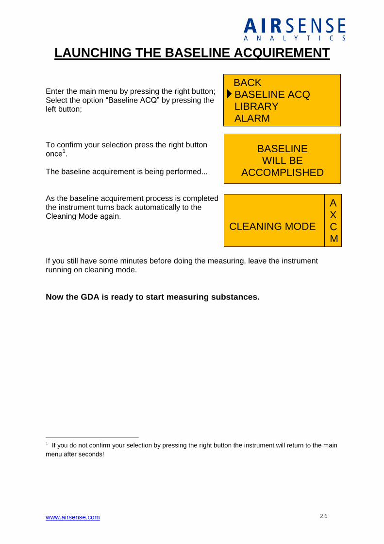
LAUNCHING THE BASELINE ACQUIREMENT Enter the main menu by pressing the right button; Select the option “Baseline ACQ” by pressing the left button; To confirm your selection press the right button once1. The baseline acquirement is being performed... As the baseline acquirement process is completed the instrument turns back automatically to the Cleaning Mode again. If you still have some minutes before doing the measuring, leave the instrument running on cleaning mode.
Now the GDA is ready to start measuring substances.
1 If you do not confirm your selection by pressing the right button the instrument will return to the main
menu after seconds!
CLEANING MODE
A X C M
www.airsense.com 27
LAUNCHING THE GDA MODE:
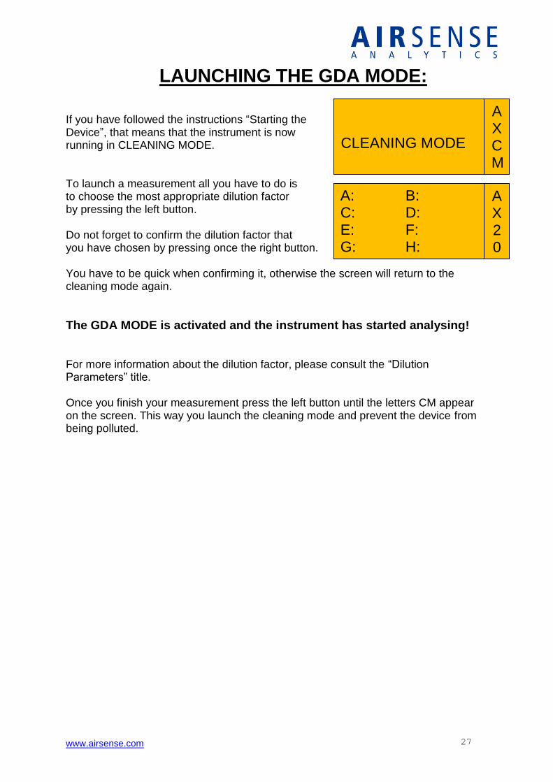
If you have followed the instructions “Starting the Device”, that means that the instrument is now running in CLEANING MODE. To launch a measurement all you have to do is to choose the most appropriate dilution factor by pressing the left button. Do not forget to confirm the dilution factor that you have chosen by pressing once the right button. You have to be quick when confirming it, otherwise the screen will return to the cleaning mode again.
The GDA MODE is activated and the instrument has started analysing! For more information about the dilution factor, please consult the “Dilution Parameters” title. Once you finish your measurement press the left button until the letters CM appear on the screen. This way you launch the cleaning mode and prevent the device from being polluted.
CLEANING MODE
A X C M
A X 20
A: C: E: G:
B: D: F: H:
www.airsense.com 28
CLEANING MODE
A X C M
ALARM SYSTEMCHECK MON ENVIR MON SOURCE
AIR MONITORING MODE
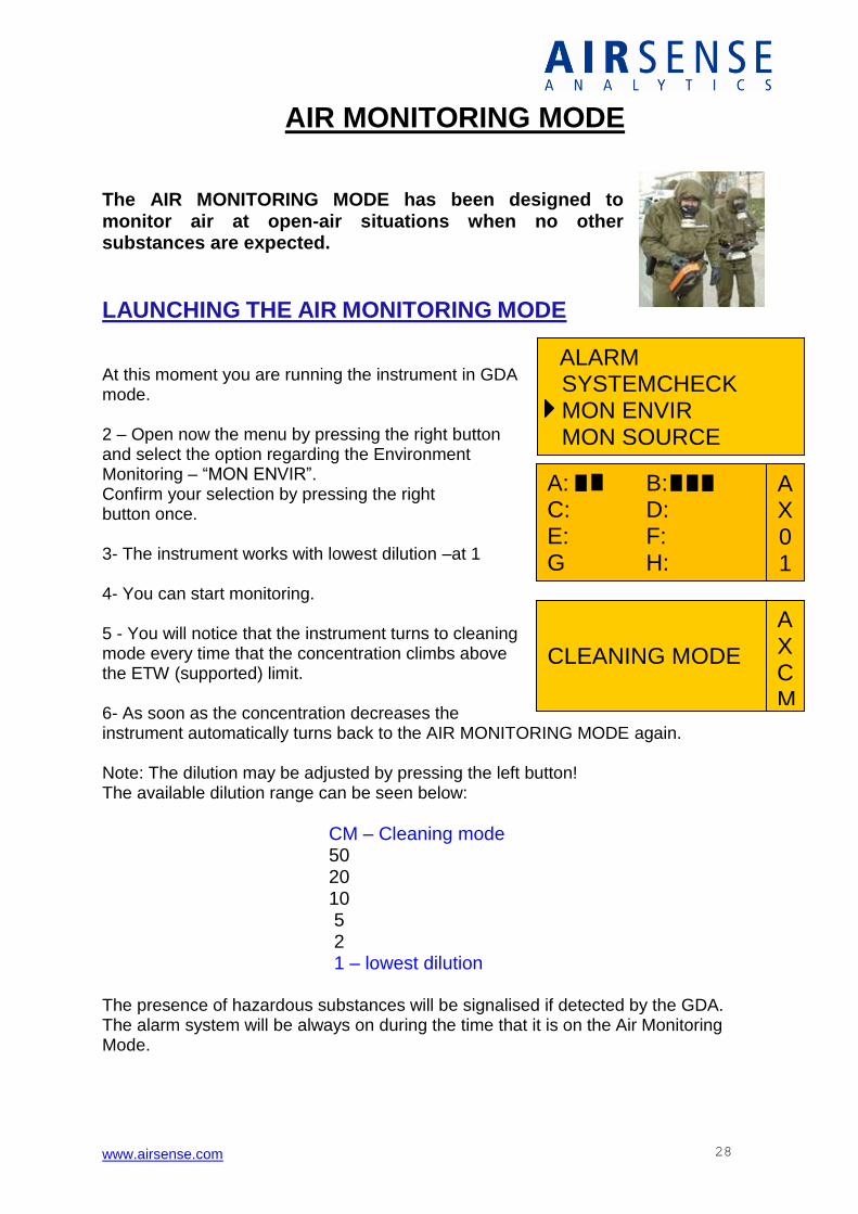
The AIR MONITORING MODE has been designed to monitor air at open-air situations when no other substances are expected.
LAUNCHING THE AIR MONITORING MODE
At this moment you are running the instrument in GDA mode. 2 – Open now the menu by pressing the right button and select the option regarding the Environment Monitoring – “MON ENVIR”. Confirm your selection by pressing the right button once. 3- The instrument works with lowest dilution –at 1 4- You can start monitoring. 5 - You will notice that the instrument turns to cleaning mode every time that the concentration climbs above the ETW (supported) limit. 6- As soon as the concentration decreases the instrument automatically turns back to the AIR MONITORING MODE again. Note: The dilution may be adjusted by pressing the left button! The available dilution range can be seen below:
CM – Cleaning mode 50 20 10 5 2 1 – lowest dilution
The presence of hazardous substances will be signalised if detected by the GDA. The alarm system will be always on during the time that it is on the Air Monitoring Mode.
A X 0 1
A: C: E: G:
B: D: F: H:
www.airsense.com 29
A X 2 0
A: C: E: G:
B: D: F: H:
CLEANING MODE
A X C M
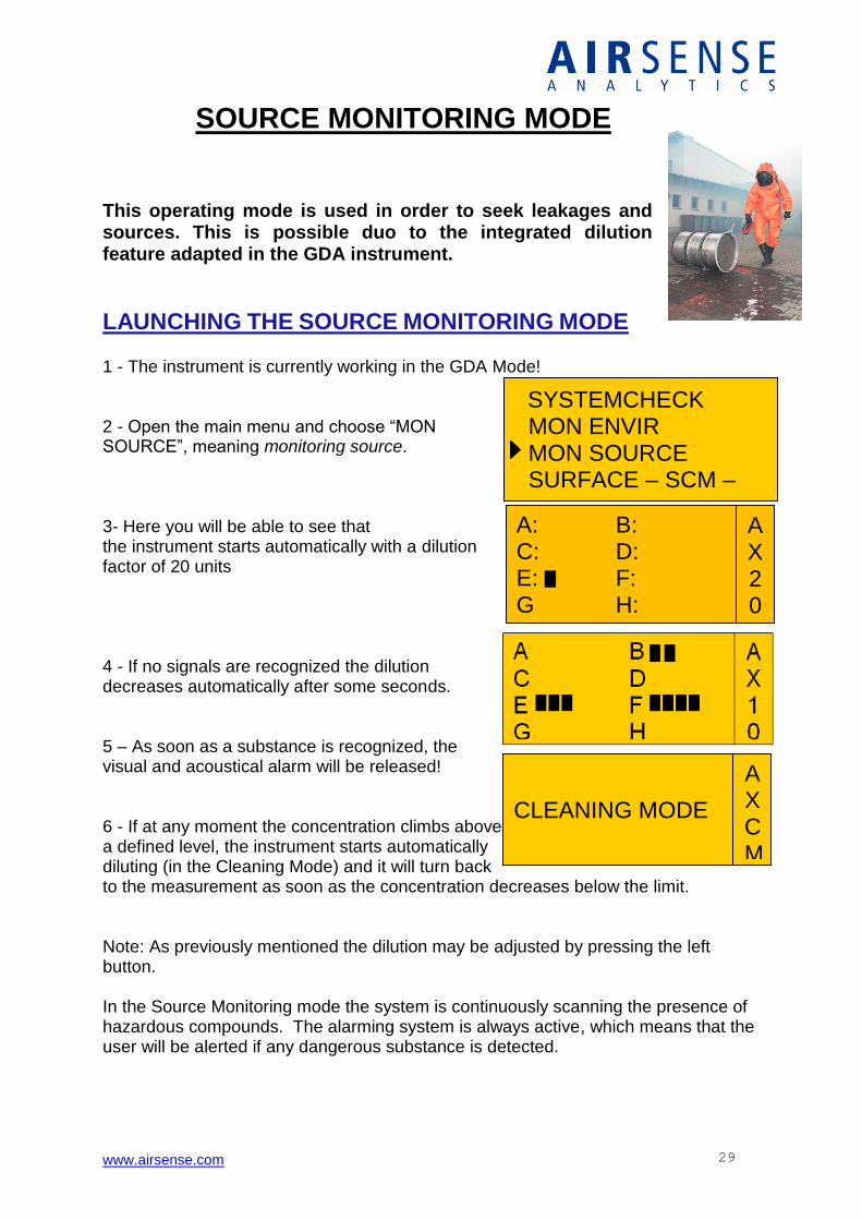
SOURCE MONITORING MODE This operating mode is used in order to seek leakages and sources. This is possible duo to the integrated dilution feature adapted in the GDA instrument.
LAUNCHING THE SOURCE MONITORING MODE
1 - The instrument is currently working in the GDA Mode! 2 - Open the main menu and choose “MON SOURCE”, meaning monitoring source. 3- Here you will be able to see that the instrument starts automatically with a dilution factor of 20 units
4 - If no signals are recognized the dilution decreases automatically after some seconds. 5 – As soon as a substance is recognized, the visual and acoustical alarm will be released! 6 - If at any moment the concentration climbs above a defined level, the instrument starts automatically diluting (in the Cleaning Mode) and it will turn back to the measurement as soon as the concentration decreases below the limit. Note: As previously mentioned the dilution may be adjusted by pressing the left button. In the Source Monitoring mode the system is continuously scanning the presence of hazardous compounds. The alarming system is always active, which means that the user will be alerted if any dangerous substance is detected.
SYSTEMCHECK MON ENVIR MON SOURCE SURFACE – SCM –
www.airsense.com 30
EXAMPLE SITUATION: 1 - An accident involving a transport train with chemical loaded tanks has been reported. On the way to the danger zone, you: - make sure that you have removed the caps from the inlets and outlets, - turn the GDA on; - check that the instrument had enough time to heat up; - if possible perform the baseline acquirement process; - verify if the SOUND ALARM is ON; You have your protection equipment on and because you are not sure about which hazards compounds you are going to meet. If you still have time until doing the measurement, leave the instrument running in Cleaning Mode! Arriving to the danger area, turn to GDA Mode: Since there are very high concentrations of substances to expect, you start with a dilution factor of 1:50. If there is no response from the device within 10 seconds, then you reduce the dilution factor to 1:20 or less until you get a response. The named substances and its concentration should give you a hint of how to put in place the established safety procedures. Do not forget to: - communicate with the team to get information on the substances; - check if there are any additional hazards to be taken into account; - if there is a fire do not forget to check how the substance reacts in contact with other substances (water, f.ex.) ; Nonetheless, be prepared to the fact that the device will enter in Cleaning Mode as soon as the concentration limit of a substance is exceeded.
www.airsense.com 31
CHANGE TO PID – MODE?
YES NO
0 PPM ACETONE ETW 500.0 PPM
A X C M
SURFACE – SCM – IMS ONLY PID ONLY ADMIN LEVEL
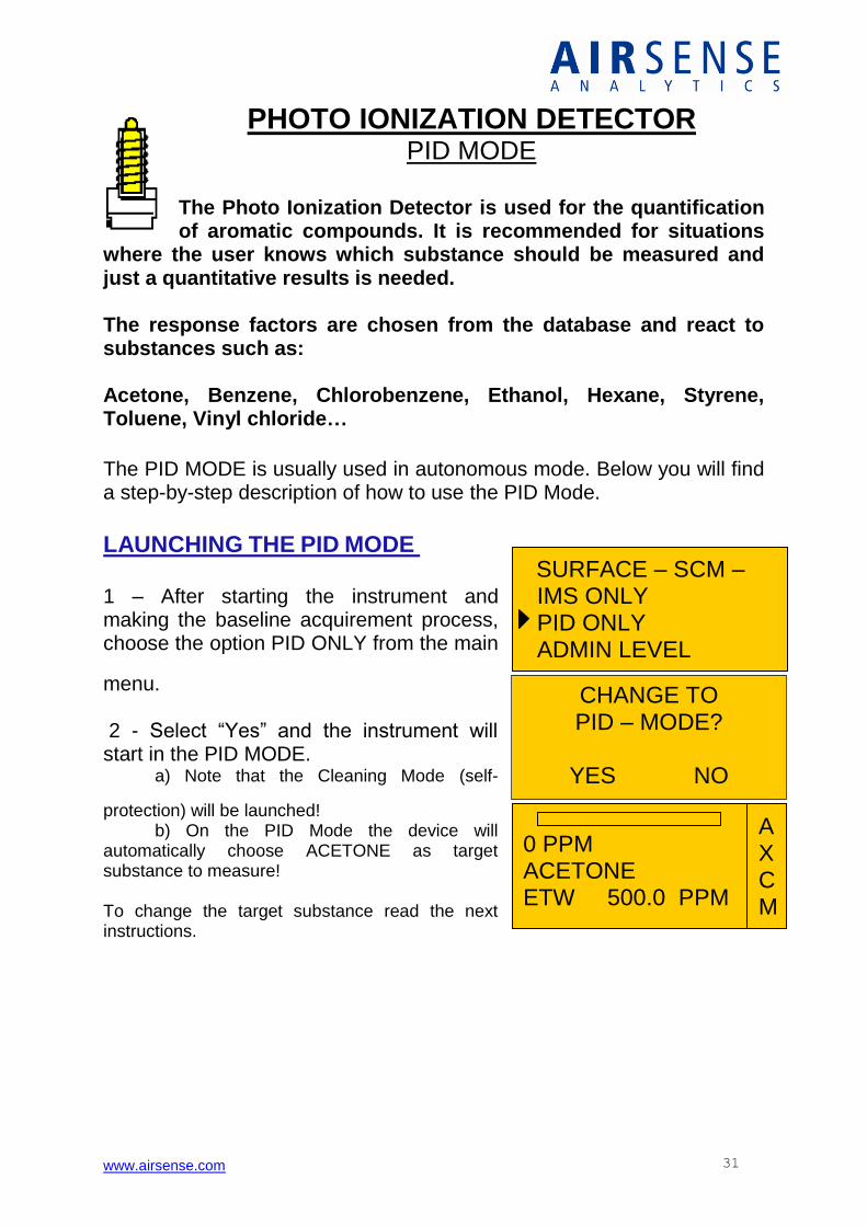
PHOTO IONIZATION DETECTOR PID MODE
The Photo Ionization Detector is used for the quantification of aromatic compounds. It is recommended for situations
where the user knows which substance should be measured and just a quantitative results is needed. The response factors are chosen from the database and react to substances such as: Acetone, Benzene, Chlorobenzene, Ethanol, Hexane, Styrene, Toluene, Vinyl chloride…
The PID MODE is usually used in autonomous mode. Below you will find a step-by-step description of how to use the PID Mode.
LAUNCHING THE PID MODE 1 – After starting the instrument and making the baseline acquirement process, choose the option PID ONLY from the main
menu. 2 - Select “Yes” and the instrument will start in the PID MODE. a) Note that the Cleaning Mode (self-
protection) will be launched! b) On the PID Mode the device will automatically choose ACETONE as target substance to measure! To change the target substance read the next instructions.
www.airsense.com 32
BACK MON ENVIR MON SOURCE SUBSTANCES
0 PPM BENZENE ETW 20.0 PPM
A X C M
11 PPM BENZENE ETW 20.0 PPM
A X 2 0
BENZENE RESPONSE: 0.53 ETW: 20.0 PPM
SELECT CONTINUE
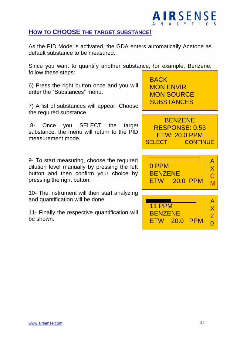
HOW TO CHOOSE THE TARGET SUBSTANCE! As the PID Mode is activated, the GDA enters automatically Acetone as default substance to be measured. Since you want to quantify another substance, for example, Benzene, follow these steps: 6) Press the right button once and you will enter the “Substances” menu.
7) A list of substances will appear. Choose the required substance. 8- Once you SELECT the target substance, the menu will return to the PID measurement mode.
9- To start measuring, choose the required dilution level manually by pressing the left button and then confirm your choice by pressing the right button. 10- The instrument will then start analyzing and quantification will be done. 11- Finally the respective quantification will be shown.
www.airsense.com 33
CLEANING MODE
A X C M
If you are not sure about which dilution factor to use, enter the menu by pressing the right button and there you will see two options which may suit the best to your case: MON ENVIR – The option “Monitor Environment” is suited for situations where you may have to deal with higher concentration values on the target substance. For example, let’s imagine that there is an unusual high concentration of toluene inside a room. Choose toluene as target substance and then select MON ENVIR option to quantify it. The instrument will automatically search for the ideal dilution factor in order to respond on the concentration factor starting from 1:50, 1:20, ... , 1:1. MON SOURCE – The option “Monitor Source” is suited for situations where it is expected to find very low concentrations of the target substance. For example, it is suspected that there is a very fine leakage in one gas pipeline. Choose the target substance and select MON SOURCE from the menu. The instrument will automatically start from the lowest dilution factor to the higher (from 1:1, 1:2, 1:5, ..., 1:50) until the source of the leakage is detected.
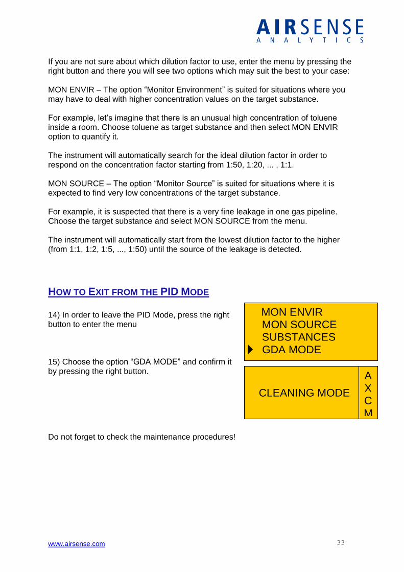
HOW TO EXIT FROM THE PID MODE 14) In order to leave the PID Mode, press the right button to enter the menu 15) Choose the option “GDA MODE” and confirm it by pressing the right button. Do not forget to check the maintenance procedures!
MON ENVIR MON SOURCE SUBSTANCES
GDA MODE
www.airsense.com 34
SUBSTANCE IDENTIFICATION ON AMMONIA CHEMISTRY SET UP
DETECTION OF CHEMICAL WARFARE AGENTS
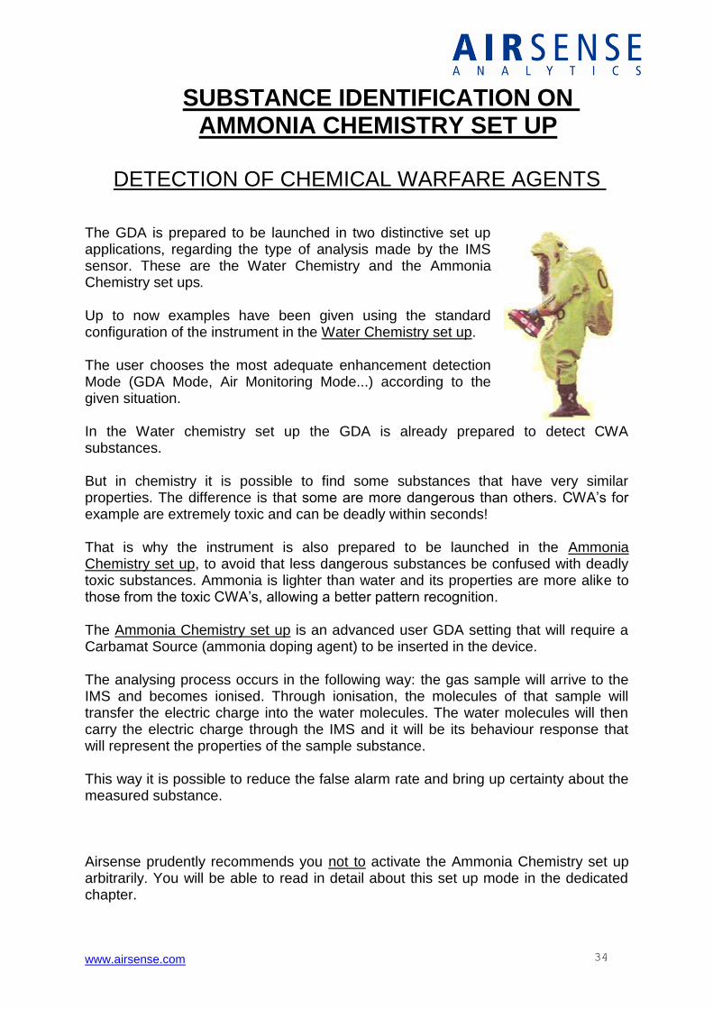
The GDA is prepared to be launched in two distinctive set up applications, regarding the type of analysis made by the IMS sensor. These are the Water Chemistry and the Ammonia Chemistry set ups. Up to now examples have been given using the standard configuration of the instrument in the Water Chemistry set up. The user chooses the most adequate enhancement detection Mode (GDA Mode, Air Monitoring Mode...) according to the given situation. In the Water chemistry set up the GDA is already prepared to detect CWA substances. But in chemistry it is possible to find some substances that have very similar properties. The difference is that some are more dangerous than others. CWA’s for example are extremely toxic and can be deadly within seconds! That is why the instrument is also prepared to be launched in the Ammonia Chemistry set up, to avoid that less dangerous substances be confused with deadly toxic substances. Ammonia is lighter than water and its properties are more alike to those from the toxic CWA’s, allowing a better pattern recognition. The Ammonia Chemistry set up is an advanced user GDA setting that will require a Carbamat Source (ammonia doping agent) to be inserted in the device. The analysing process occurs in the following way: the gas sample will arrive to the IMS and becomes ionised. Through ionisation, the molecules of that sample will transfer the electric charge into the water molecules. The water molecules will then carry the electric charge through the IMS and it will be its behaviour response that will represent the properties of the sample substance. This way it is possible to reduce the false alarm rate and bring up certainty about the measured substance. Airsense prudently recommends you not to activate the Ammonia Chemistry set up arbitrarily. You will be able to read in detail about this set up mode in the dedicated chapter.

www.airsense.com 35
AMMONIA CHEMISTRY - GDA SET UP
Let’s suppose the user is doing a measurement on the GDA Mode and detects the presence of a chemical warfare agent. To be sure that it is in fact a CWA he decides to activate the Ammonia Chemistry set up on the device. To do so the steps to follow are: 1 - Inserting an ammonia carbamat source (the ammonia doping substance) in the device.
HOW TO INSERT THE AMMONIA SOURCE Remove protective cap by using the service tool
Break the glass vial in two parts and take out the Ammonia rod...
…now insert it in the slot and close it with the cap.
2 - Starting the GDA and entering in the mode IMS ONLY. Wait while the self-test is being accomplished. 3 – Leave the current screen by pressing button under the stop sign and with the left button enter the Item “Library”. 4 - Activate the library ”B”. 5 – Wait for the normal IMS screen to appear and the instrument is ready to go. The Ammonia Chemistry set up is launched, the GDA is ready. Make sure that you are wearing all the necessary protections!
www.airsense.com 36
Notes ! This procedure is recommended for maximum safety. Should Chemical Warfare Agents be displayed in the GDA it is recommended to switch the instrument instantly in IMS Mode. The sensors Photo Ionisation Detector, Semiconductors and the Electrochemical Cell are not used for the identification of CWA’s. In IMS Mode two libraries may be used. Library A is chosen in order to use the IMS on water chemistry, Library B is chosen to use the IMS on Ammonia basis. While on the IMS Mode the instrument can only be used only for the detection of Chemical Warfare Agents – no toxic industrial chemicals can now be detected or identified.
WARNING !
It will take many hours – much more than the usual - to take the Ammonia gas out of the system. It is therefore advised to run the instrument in dilution mode until the sensor cells are clear again. The user will know whether the instrument is ready or not by observing the IMS Spectra or by taking a look at the channel A. Please use Ammonia only when Chemical Warfare Agents are expected!
www.airsense.com 37
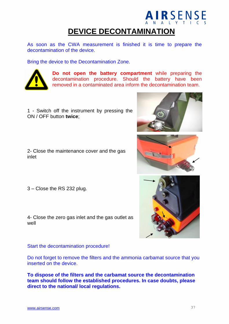
DEVICE DECONTAMINATION As soon as the CWA measurement is finished it is time to prepare the decontamination of the device. Bring the device to the Decontamination Zone.
Do not open the battery compartment while preparing the decontamination procedure. Should the battery have been removed in a contaminated area inform the decontamination team.
1 - Switch off the instrument by pressing the ON / OFF button twice; 2- Close the maintenance cover and the gas inlet
3 – Close the RS 232 plug. 4- Close the zero gas inlet and the gas outlet as well Start the decontamination procedure! Do not forget to remove the filters and the ammonia carbamat source that you inserted on the device. To dispose of the filters and the carbamat source the decontamination team should follow the established procedures. In case doubts, please direct to the national/ local regulations.
www.airsense.com 38
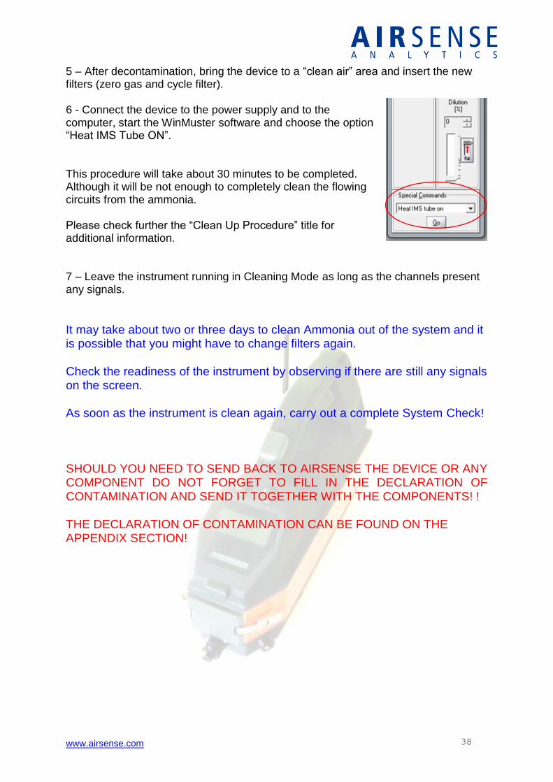
5 – After decontamination, bring the device to a “clean air” area and insert the new filters (zero gas and cycle filter). 6 - Connect the device to the power supply and to the computer, start the WinMuster software and choose the option “Heat IMS Tube ON”. This procedure will take about 30 minutes to be completed. Although it will be not enough to completely clean the flowing circuits from the ammonia. Please check further the “Clean Up Procedure” title for additional information. 7 – Leave the instrument running in Cleaning Mode as long as the channels present any signals.
It may take about two or three days to clean Ammonia out of the system and it is possible that you might have to change filters again. Check the readiness of the instrument by observing if there are still any signals on the screen. As soon as the instrument is clean again, carry out a complete System Check! SHOULD YOU NEED TO SEND BACK TO AIRSENSE THE DEVICE OR ANY COMPONENT DO NOT FORGET TO FILL IN THE DECLARATION OF CONTAMINATION AND SEND IT TOGETHER WITH THE COMPONENTS! ! THE DECLARATION OF CONTAMINATION CAN BE FOUND ON THE APPENDIX SECTION!

www.airsense.com 39
MON ENVIR MON SOURCE SURFACE -SCM- IMS ONLY
SCM TOOL - ANALYSING DECONTAMINATED SURFACES
The Surface Contamination Tool is installed in front of the GDA and it was designed to investigate surfaces like gloves, boots or overalls. Using the Surface Contamination Tool it becomes possible to verify if the decontamination procedure was successful or if it has to be repeated.
CONNECTING THE SCM TOOL
1- The SCM tool can only be used by plugging the GDA to the 230 V / AC (110 VAC) power supply. 2 - After connecting the device to the power supply remove the maintenance cover by pulling back the brackets and connect the SCM tool in front of the GDA. 3- Once the device is initiated open the main menu and select the option “SURFACE -SCM-“ 4 - The lamp is launched by pressing the left button once – the light time is usually of about 3 seconds.
www.airsense.com 40
IMS ONLY PID ONLY ADMIN LEVEL
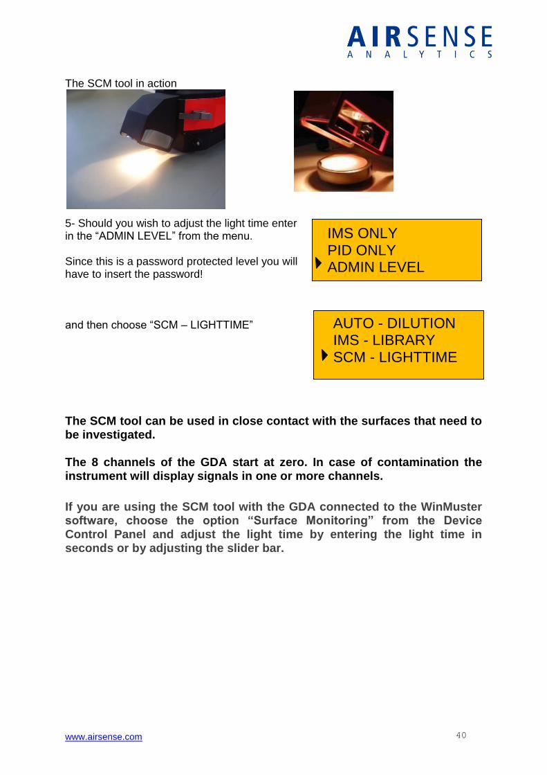
The SCM tool in action
5- Should you wish to adjust the light time enter in the “ADMIN LEVEL” from the menu. Since this is a password protected level you will have to insert the password! and then choose “SCM – LIGHTTIME”
The SCM tool can be used in close contact with the surfaces that need to be investigated. The 8 channels of the GDA start at zero. In case of contamination the instrument will display signals in one or more channels.
If you are using the SCM tool with the GDA connected to the WinMuster software, choose the option “Surface Monitoring” from the Device Control Panel and adjust the light time by entering the light time in seconds or by adjusting the slider bar.
AUTO - DILUTION IMS - LIBRARY SCM - LIGHTTIME
www.airsense.com 41
CLEAN UP PROCEDURE The following deductions are an indication that the GDA needs to be cleaned up to be in optimum operating condition:
When the requirements for acceptable operating conditions are not met
The Sensor check failed saying that Instrument is not clean
The RIP stays below 250 in height. Contamination is revealed by peaks in the spectra that won’t decline.
Ammonia is persistent in the system (peak at K0 = 2.35, positive spectrum)
- During the clean up procedure the GDA cannot be used for normal
measurement. - The clean up procedure can take at least one hour. Depending on the
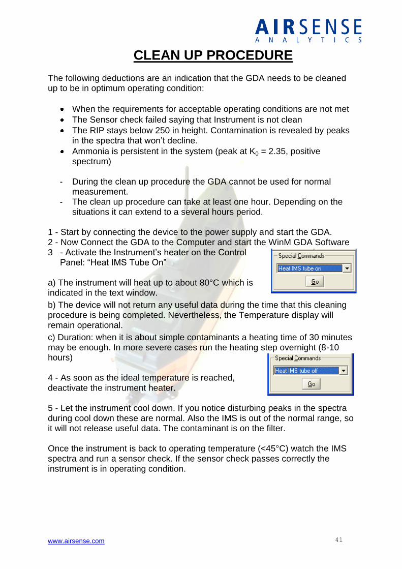
situations it can extend to a several hours period. 1 - Start by connecting the device to the power supply and start the GDA. 2 - Now Connect the GDA to the Computer and start the WinM GDA Software 3 - Activate the Instrument’s heater on the Control
Panel: “Heat IMS Tube On” a) The instrument will heat up to about 80°C which is indicated in the text window.
b) The device will not return any useful data during the time that this cleaning procedure is being completed. Nevertheless, the Temperature display will remain operational.
c) Duration: when it is about simple contaminants a heating time of 30 minutes may be enough. In more severe cases run the heating step overnight (8-10 hours) 4 - As soon as the ideal temperature is reached, deactivate the instrument heater. 5 - Let the instrument cool down. If you notice disturbing peaks in the spectra during cool down these are normal. Also the IMS is out of the normal range, so it will not release useful data. The contaminant is on the filter. Once the instrument is back to operating temperature (<45°C) watch the IMS spectra and run a sensor check. If the sensor check passes correctly the instrument is in operating condition.
www.airsense.com 42
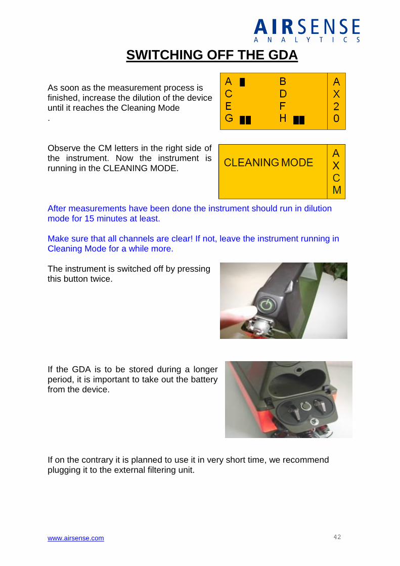
SWITCHING OFF THE GDA As soon as the measurement process is finished, increase the dilution of the device until it reaches the Cleaning Mode . Observe the CM letters in the right side of the instrument. Now the instrument is running in the CLEANING MODE. After measurements have been done the instrument should run in dilution mode for 15 minutes at least. Make sure that all channels are clear! If not, leave the instrument running in Cleaning Mode for a while more. The instrument is switched off by pressing this button twice. If the GDA is to be stored during a longer period, it is important to take out the battery from the device. If on the contrary it is planned to use it in very short time, we recommend plugging it to the external filtering unit.
www.airsense.com 43
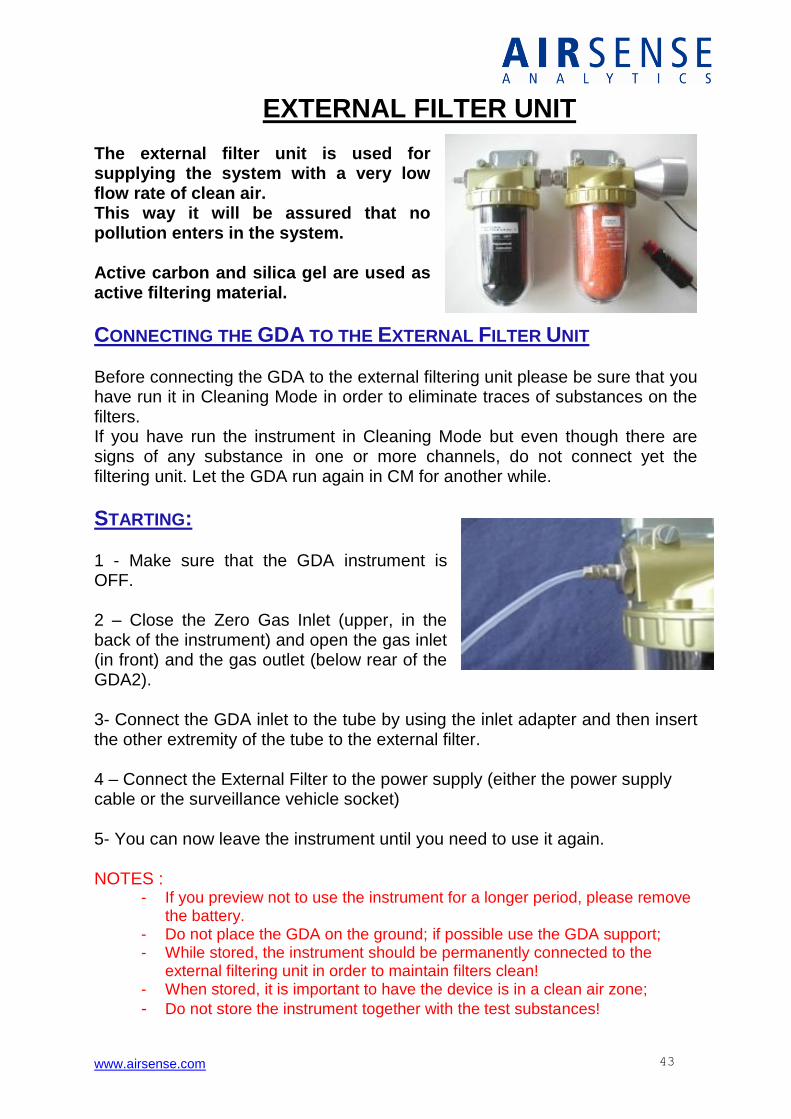
EXTERNAL FILTER UNIT The external filter unit is used for supplying the system with a very low flow rate of clean air. This way it will be assured that no pollution enters in the system. Active carbon and silica gel are used as active filtering material.
CONNECTING THE GDA TO THE EXTERNAL FILTER UNIT Before connecting the GDA to the external filtering unit please be sure that you have run it in Cleaning Mode in order to eliminate traces of substances on the filters. If you have run the instrument in Cleaning Mode but even though there are signs of any substance in one or more channels, do not connect yet the filtering unit. Let the GDA run again in CM for another while.
STARTING: 1 - Make sure that the GDA instrument is OFF. 2 – Close the Zero Gas Inlet (upper, in the back of the instrument) and open the gas inlet (in front) and the gas outlet (below rear of the GDA2). 3- Connect the GDA inlet to the tube by using the inlet adapter and then insert the other extremity of the tube to the external filter. 4 – Connect the External Filter to the power supply (either the power supply cable or the surveillance vehicle socket) 5- You can now leave the instrument until you need to use it again. NOTES :
- If you preview not to use the instrument for a longer period, please remove the battery.
- Do not place the GDA on the ground; if possible use the GDA support; - While stored, the instrument should be permanently connected to the
external filtering unit in order to maintain filters clean! - When stored, it is important to have the device is in a clean air zone;
- Do not store the instrument together with the test substances!
www.airsense.com 44
NON AUTONOMOUS USE
MEASURING WITH WINMUSTER
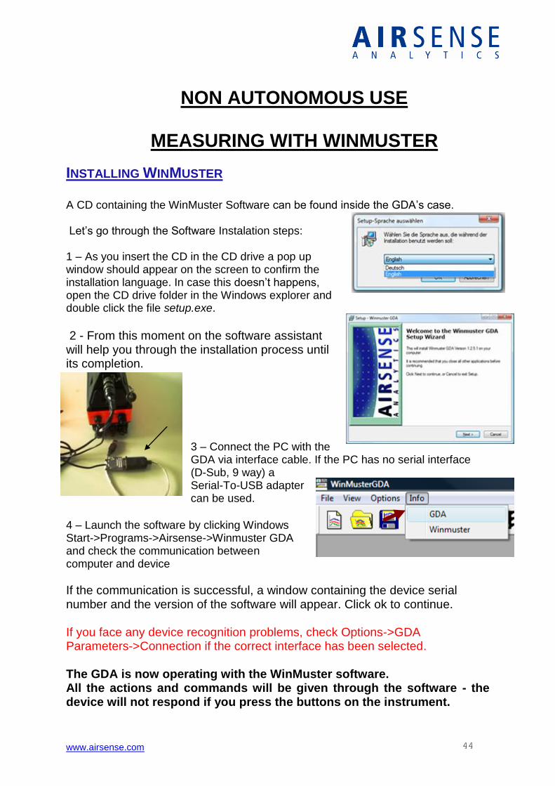
INSTALLING WINMUSTER A CD containing the WinMuster Software can be found inside the GDA’s case. Let’s go through the Software Instalation steps: 1 – As you insert the CD in the CD drive a pop up window should appear on the screen to confirm the installation language. In case this doesn’t happens, open the CD drive folder in the Windows explorer and double click the file setup.exe.
2 - From this moment on the software assistant will help you through the installation process until its completion.
3 – Connect the PC with the GDA via interface cable. If the PC has no serial interface (D-Sub, 9 way) a Serial-To-USB adapter can be used.
4 – Launch the software by clicking Windows Start->Programs->Airsense->Winmuster GDA and check the communication between computer and device
If the communication is successful, a window containing the device serial number and the version of the software will appear. Click ok to continue. If you face any device recognition problems, check Options->GDA Parameters->Connection if the correct interface has been selected. The GDA is now operating with the WinMuster software. All the actions and commands will be given through the software - the device will not respond if you press the buttons on the instrument.
www.airsense.com 45
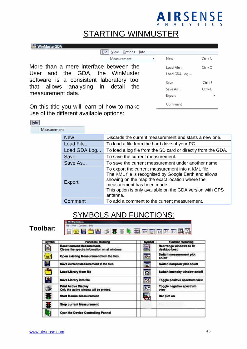
STARTING WINMUSTER
New Discards the current measurement and starts a new one.
Load File... To load a file from the hard drive of your PC.
Load GDA Log... To load a log file from the SD card or directly from the GDA.
Save To save the current measurement.
Save As... To save the current measurement under another name.
Export
To export the current measurement into a KML file. The KML file is recognised by Google Earth and allows showing on the map the exact location where the measurement has been made. This option is only available on the GDA version with GPS antenna.
Comment To add a comment to the current measurement.
SYMBOLS AND FUNCTIONS:
Toolbar:
More than a mere interface between the User and the GDA, the WinMuster software is a consistent laboratory tool that allows analysing in detail the measurement data. On this title you will learn of how to make use of the different available options:
www.airsense.com 46
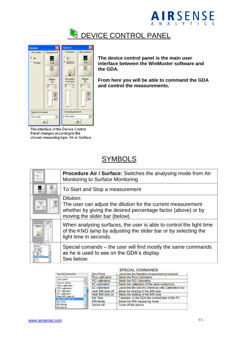
DEVICE CONTROL PANEL
The device control panel is the main user interface between the WinMuster software and the GDA. From here you will be able to command the GDA and control the measurements.
SYMBOLS
Procedure Air / Surface: Switches the analysing mode from Air Monitoring to Surface Monitoring
To Start and Stop a measurement
Dilution: The user can adjust the dilution for the current measurement whether by giving the desired percentage factor (above) or by moving the slider bar (below)
When analysing surfaces, the user is able to control the light time of the KNG lamp by adjusting the slider bar or by selecting the light time in seconds.
Special comands – the user will find mostly the same commands as he is used to see on the GDA’s display. See below:
www.airsense.com 47
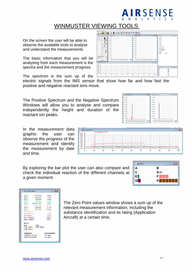
WINMUSTER VIEWING TOOLS On the screen the user will be able to observe the available tools to analyse and understand the measurements. The basic information that you will be analysing from each measurement is the spectra and the measurement progress. The spectrum is the sum up of the
electric signals from the IMS sensor that show how far and how fast the positive and negative reactant ions move. The Positive Spectrum and the Negative Spectrum Windows will allow you to analyse and compare independently the height and duration of the reactant ion peaks. In the measurement data graphic the user can observe the progress of the measurement and identify the measurement by date and time. By exploring the bar plot the user can also compare and check the individual reaction of the different channels at a given moment.
The Zero Point values window shows a sum up of the relevant measurement information, including the substance identification and its rating (Application Aircraft) at a certain time.
www.airsense.com 48
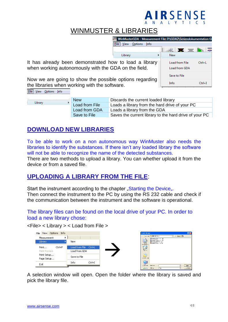
WINMUSTER & LIBRARIES It has already been demonstrated how to load a library when working autonomously with the GDA on the field. Now we are going to show the possible options regarding the libraries when working with the software.
DOWNLOAD NEW LIBRARIES
To be able to work on a non autonomous way WinMuster also needs the libraries to identify the substances. If there isn’t any loaded library the software will not be able to recognize the name of the detected substances. There are two methods to upload a library. You can whether upload it from the device or from a saved file.
UPLOADING A LIBRARY FROM THE FILE: Start the instrument according to the chapter „Starting the Device„. Then connect the instrument to the PC by using the RS 232 cable and check if the communication between the instrument and the software is operational.
The library files can be found on the local drive of your PC. In order to load a new library chose:
<File> < Library > < Load from File >
A selection window will open. Open the folder where the library is saved and pick the library file.
New Discards the current loaded library
Load from File Loads a library from the hard drive of your PC
Load from GDA Loads a library from the GDA
Save to File Saves the current library to the hard drive of your PC
www.airsense.com 49
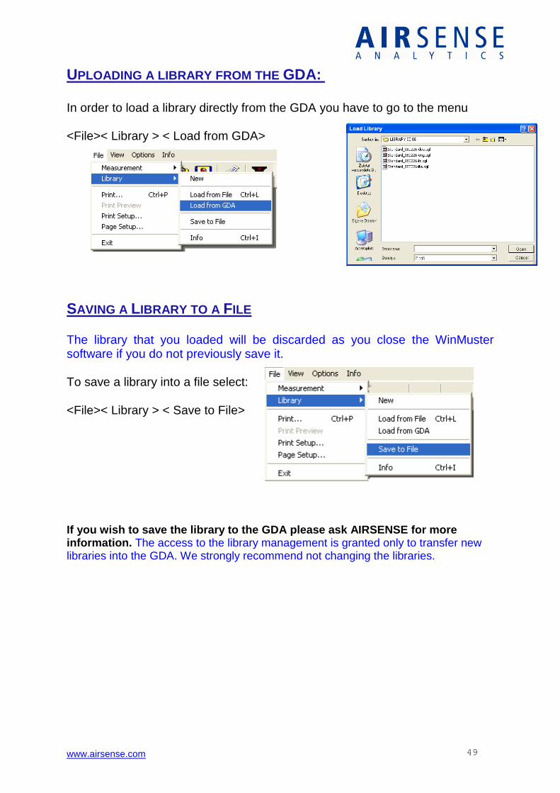
UPLOADING A LIBRARY FROM THE GDA: In order to load a library directly from the GDA you have to go to the menu <File>< Library > < Load from GDA>
SAVING A LIBRARY TO A FILE The library that you loaded will be discarded as you close the WinMuster software if you do not previously save it. To save a library into a file select: <File>< Library > < Save to File>
If you wish to save the library to the GDA please ask AIRSENSE for more information. The access to the library management is granted only to transfer new libraries into the GDA. We strongly recommend not changing the libraries.
www.airsense.com 50
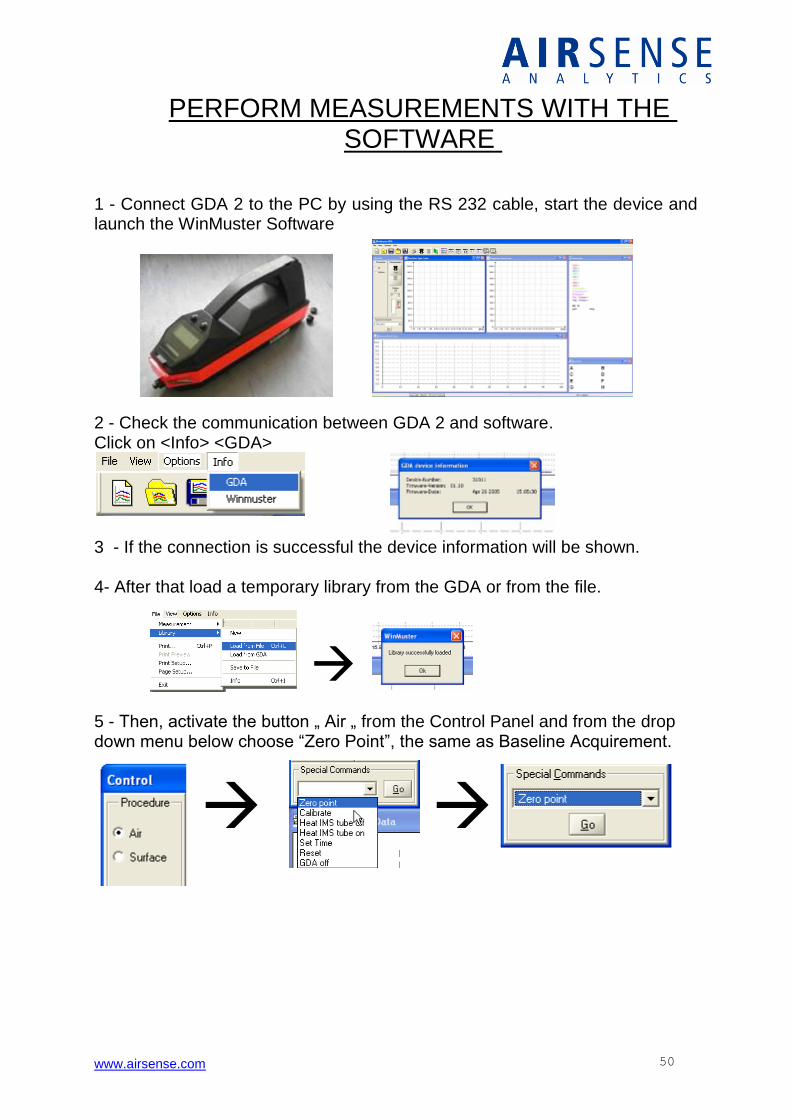
PERFORM MEASUREMENTS WITH THE SOFTWARE
1 - Connect GDA 2 to the PC by using the RS 232 cable, start the device and launch the WinMuster Software 2 - Check the communication between GDA 2 and software. Click on <Info> <GDA>
3 - If the connection is successful the device information will be shown. 4- After that load a temporary library from the GDA or from the file.
5 - Then, activate the button „ Air „ from the Control Panel and from the drop down menu below choose “Zero Point”, the same as Baseline Acquirement.

www.airsense.com 51
6 - In order to protect the system against high gas concentrations, set the dilution to maximum with this button The value of the dilution can be variably adjusted afterwards by using the slider or the spin buttons above it. 7 -The measurement is launched by pressing the button START. While measuring the dilution should be decreased until one or more channels are responding and the identification result appears. Among the information that is shown, you will be able to observe:
- Identification results - Concentrations - Temperature - Measurement Progress

www.airsense.com 52
DATA LOGGER: To explain how the measurement data is compiled and transferred from the GDA, let’s go back to back to the device.
The data logger keeps records of all the measurements done autonomously with the GDA. This function is automatically activated each time the instrument is launched. The measurement information will be saved into the SD card lodged in the maintenance panel of the device.
On the other hand, if the GDA is currently doing a measurement connected to the WinMuster software, the data logger won’t be active and won’t be saving any information. On this case, the measurement information will be displayed directly in the computer and it will be up to the user to choose saving this information to the hard drive or not. The current data logger saving capacity is of 1 GB – enough for a period of about 100 hours of measurements. Warnings about SD card:
1. If you are faced with a warning message like "The file system on the memory card is damaged" when you try to access the card on your PC simply ignore this message. Don't follow the message to repair the file system. Otherwise all data may be lost.
2. Do not erase the file data.bin !
3. Do not open the SD card with other software than WinMuster
4. Do not store any other files on the memory card.
www.airsense.com 53
READING THE DATA LOGGER FROM THE GDA
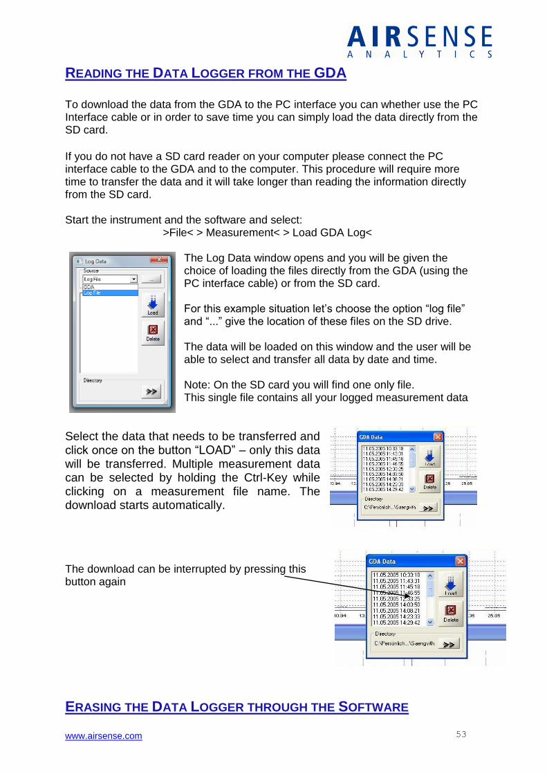
To download the data from the GDA to the PC interface you can whether use the PC Interface cable or in order to save time you can simply load the data directly from the SD card.
If you do not have a SD card reader on your computer please connect the PC interface cable to the GDA and to the computer. This procedure will require more time to transfer the data and it will take longer than reading the information directly from the SD card. Start the instrument and the software and select: >File< > Measurement< > Load GDA Log<
The Log Data window opens and you will be given the choice of loading the files directly from the GDA (using the PC interface cable) or from the SD card. For this example situation let’s choose the option “log file” and “...” give the location of these files on the SD drive. The data will be loaded on this window and the user will be able to select and transfer all data by date and time. Note: On the SD card you will find one only file. This single file contains all your logged measurement data
Select the data that needs to be transferred and click once on the button “LOAD” – only this data will be transferred. Multiple measurement data can be selected by holding the Ctrl-Key while clicking on a measurement file name. The download starts automatically. The download can be interrupted by pressing this button again
ERASING THE DATA LOGGER THROUGH THE SOFTWARE
www.airsense.com 54
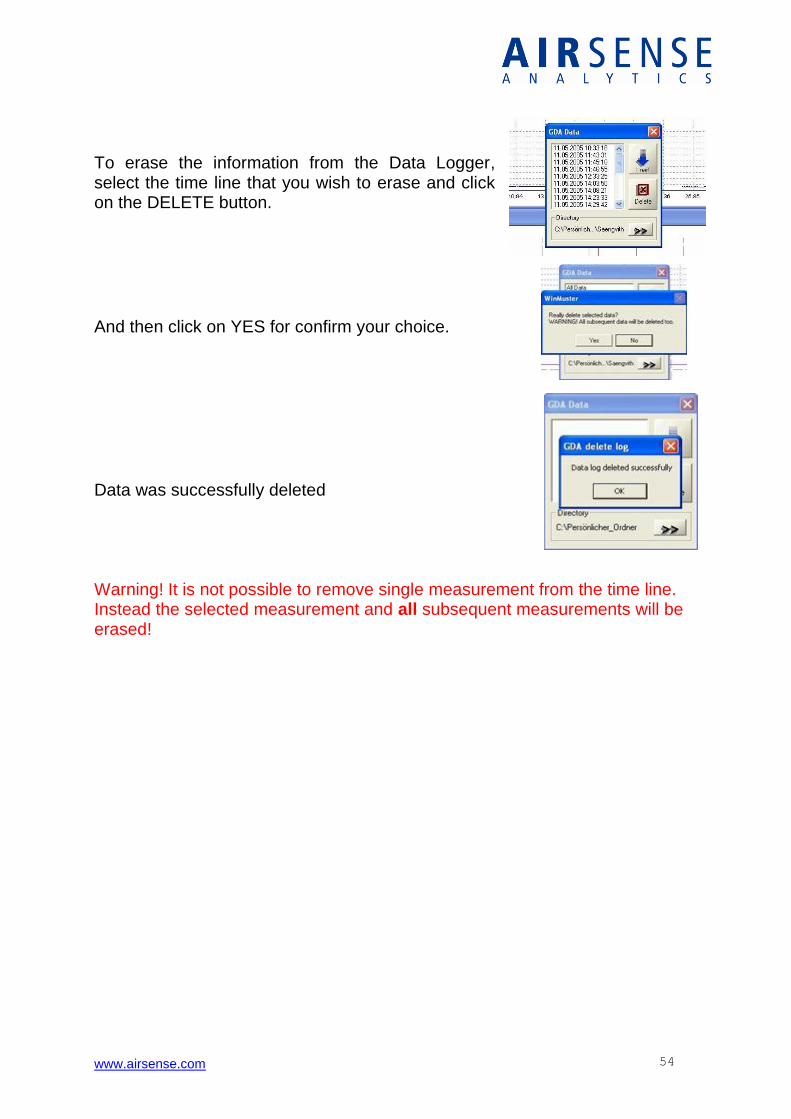
To erase the information from the Data Logger, select the time line that you wish to erase and click on the DELETE button.
And then click on YES for confirm your choice.
Data was successfully deleted Warning! It is not possible to remove single measurement from the time line. Instead the selected measurement and all subsequent measurements will be erased!
www.airsense.com 55
STATE OF MEM: 30.61PERC FULL
CA 8H52MIN LEFT CONTINUE
CONFIRM MEMORY ERASE?
YES NO
STATE ACTIVATE ERASE OPTIONS
BACK STATE ACTIVATE ERASE
BACK DATA LOGGER ALARM LOGGER IDENT MODE
IMS ONLY PID ONLY SYSTEMCHECK ADMIN LEVEL
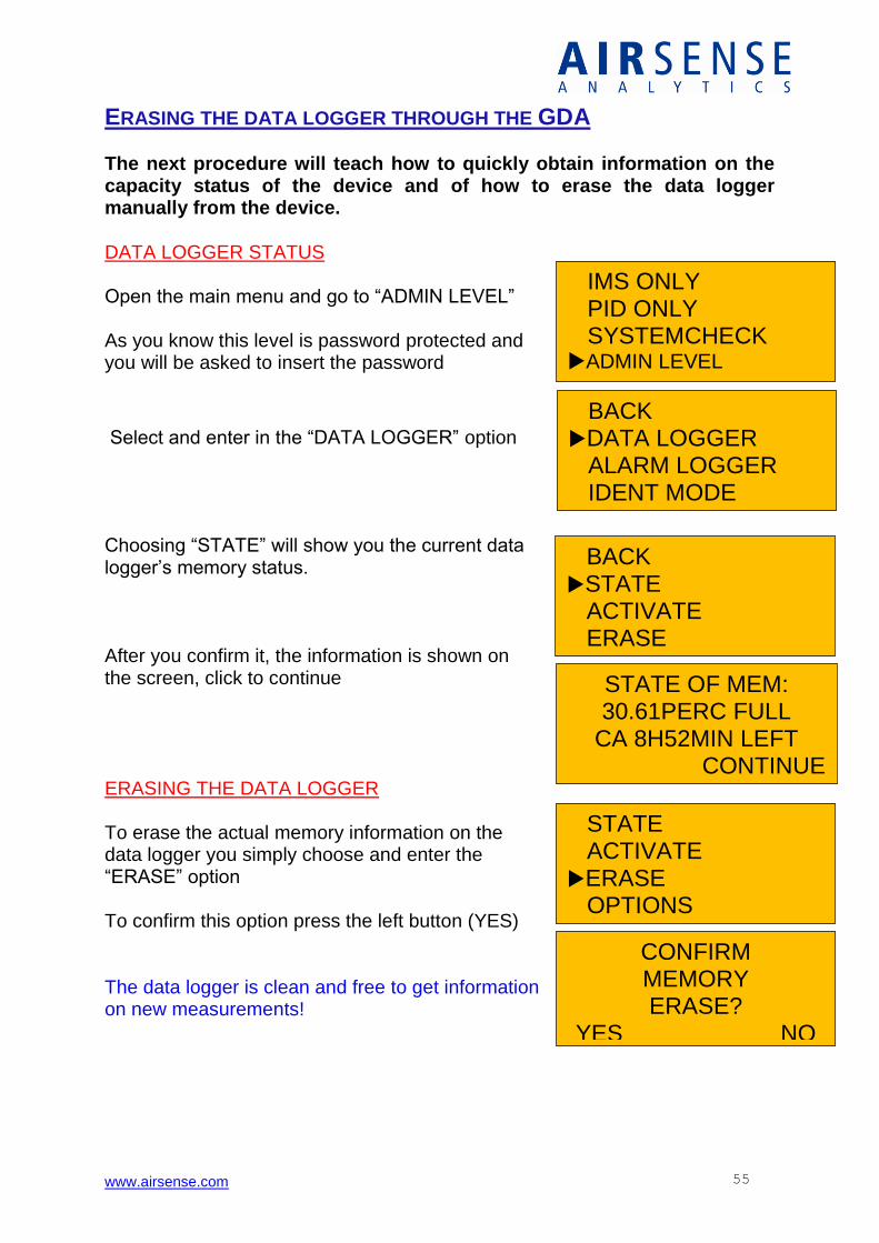
ERASING THE DATA LOGGER THROUGH THE GDA The next procedure will teach how to quickly obtain information on the capacity status of the device and of how to erase the data logger manually from the device. DATA LOGGER STATUS Open the main menu and go to “ADMIN LEVEL” As you know this level is password protected and you will be asked to insert the password
Select and enter in the “DATA LOGGER” option
Choosing “STATE” will show you the current data logger’s memory status. After you confirm it, the information is shown on the screen, click to continue ERASING THE DATA LOGGER To erase the actual memory information on the data logger you simply choose and enter the “ERASE” option To confirm this option press the left button (YES) The data logger is clean and free to get information on new measurements!
www.airsense.com 56
GDA’S APPLICATION ON A SURVEILLANCE VEHICLE
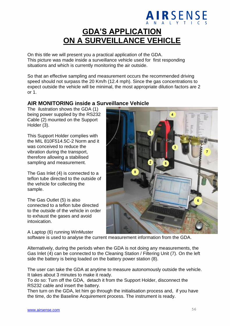
On this title we will present you a practical application of the GDA. This picture was made inside a surveillance vehicle used for first responding situations and which is currently monitoring the air outside. So that an effective sampling and measurement occurs the recommended driving speed should not surpass the 20 Km/h (12.4 mph). Since the gas concentrations to expect outside the vehicle will be minimal, the most appropriate dilution factors are 2 or 1.
AIR MONITORING inside a Surveillance Vehicle The ilustration shows the GDA (1) being power supplied by the RS232 Cable (2) mounted on the Support Holder (3). This Support Holder complies with the MIL 810F514.5C-2 Norm and it was conceived to reduce the vibration during the transport, therefore allowing a stabilised sampling and measurement. The Gas Inlet (4) is connected to a teflon tube directed to the outside of the vehicle for collecting the sample. The Gas Outlet (5) is also connected to a teflon tube directed to the outside of the vehicle in order to exhaust the gases and avoid intoxication. A Laptop (6) running WinMuster software is used to analyse the current measurement information from the GDA. Alternatively, during the periods when the GDA is not doing any measurements, the Gas Inlet (4) can be connected to the Cleaning Station / Filtering Unit (7). On the left side the battery is being loaded on the battery power station (8). The user can take the GDA at anytime to measure autonomously outside the vehicle. It takes about 3 minutes to make it ready. To do so: Turn off the GDA, detach it from the Support Holder, disconnect the RS232 cable and insert the battery. Then turn on the GDA, let him go through the initialisation process and, if you have the time, do the Baseline Acquirement process. The instrument is ready.
www.airsense.com 57
BACK + NEXT
192.168.031.011
OK
IMS ONLY ID ONLY WIRELESS
ADMIN
IMS ONLY PID ONLY WIRELESS
ADMIN
GDA OPTIONAL FEATURES
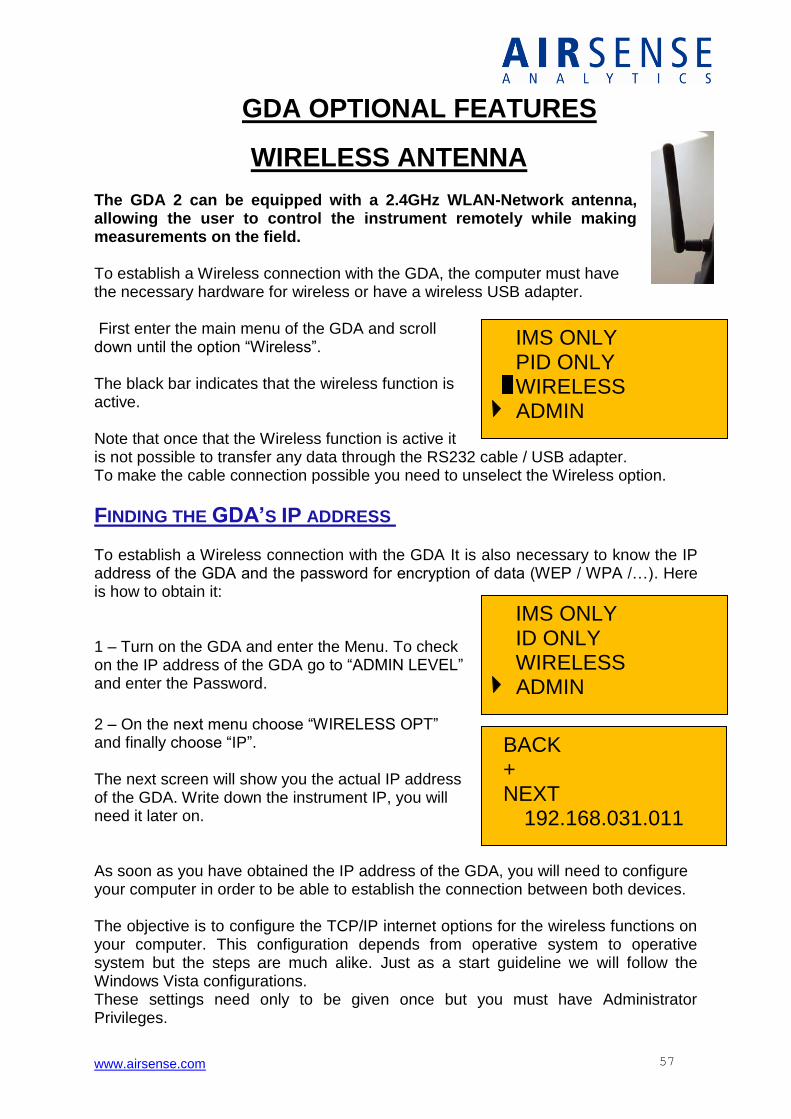
WIRELESS ANTENNA The GDA 2 can be equipped with a 2.4GHz WLAN-Network antenna, allowing the user to control the instrument remotely while making measurements on the field. To establish a Wireless connection with the GDA, the computer must have the necessary hardware for wireless or have a wireless USB adapter. First enter the main menu of the GDA and scroll down until the option “Wireless”. The black bar indicates that the wireless function is active. Note that once that the Wireless function is active it is not possible to transfer any data through the RS232 cable / USB adapter. To make the cable connection possible you need to unselect the Wireless option.
FINDING THE GDA’S IP ADDRESS To establish a Wireless connection with the GDA It is also necessary to know the IP address of the GDA and the password for encryption of data (WEP / WPA /…). Here is how to obtain it: 1 – Turn on the GDA and enter the Menu. To check on the IP address of the GDA go to “ADMIN LEVEL” and enter the Password.
2 – On the next menu choose “WIRELESS OPT” and finally choose “IP”. The next screen will show you the actual IP address of the GDA. Write down the instrument IP, you will need it later on. As soon as you have obtained the IP address of the GDA, you will need to configure your computer in order to be able to establish the connection between both devices. The objective is to configure the TCP/IP internet options for the wireless functions on your computer. This configuration depends from operative system to operative system but the steps are much alike. Just as a start guideline we will follow the Windows Vista configurations. These settings need only to be given once but you must have Administrator Privileges.
www.airsense.com 58
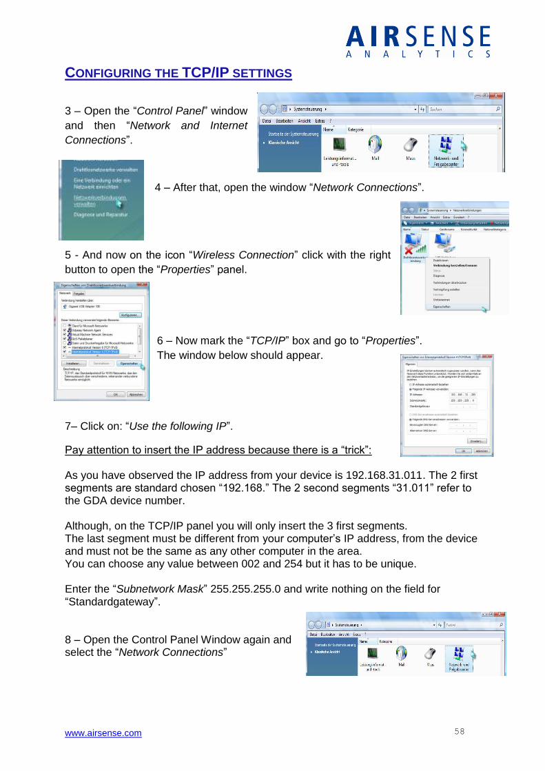
CONFIGURING THE TCP/IP SETTINGS
3 – Open the “Control Panel” window
and then “Network and Internet
Connections”.
4 – After that, open the window “Network Connections”.
5 - And now on the icon “Wireless Connection” click with the right
button to open the “Properties” panel.
6 – Now mark the “TCP/IP” box and go to “Properties”.
The window below should appear.
7– Click on: “Use the following IP”.
Pay attention to insert the IP address because there is a “trick”: As you have observed the IP address from your device is 192.168.31.011. The 2 first segments are standard chosen “192.168.” The 2 second segments “31.011” refer to the GDA device number. Although, on the TCP/IP panel you will only insert the 3 first segments. The last segment must be different from your computer’s IP address, from the device and must not be the same as any other computer in the area. You can choose any value between 002 and 254 but it has to be unique. Enter the “Subnetwork Mask” 255.255.255.0 and write nothing on the field for “Standardgateway”. 8 – Open the Control Panel Window again and select the “Network Connections”
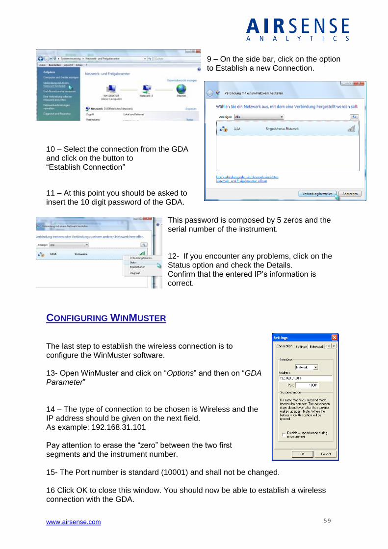
www.airsense.com 59
9 – On the side bar, click on the option to Establish a new Connection.
10 – Select the connection from the GDA and click on the button to “Establish Connection”
11 – At this point you should be asked to insert the 10 digit password of the GDA.
This password is composed by 5 zeros and the serial number of the instrument. 12- If you encounter any problems, click on the Status option and check the Details. Confirm that the entered IP’s information is correct.
CONFIGURING WINMUSTER
The last step to establish the wireless connection is to configure the WinMuster software. 13- Open WinMuster and click on “Options” and then on “GDA Parameter” 14 – The type of connection to be chosen is Wireless and the IP address should be given on the next field. As example: 192.168.31.101 Pay attention to erase the “zero” between the two first segments and the instrument number. 15- The Port number is standard (10001) and shall not be changed. 16 Click OK to close this window. You should now be able to establish a wireless connection with the GDA.
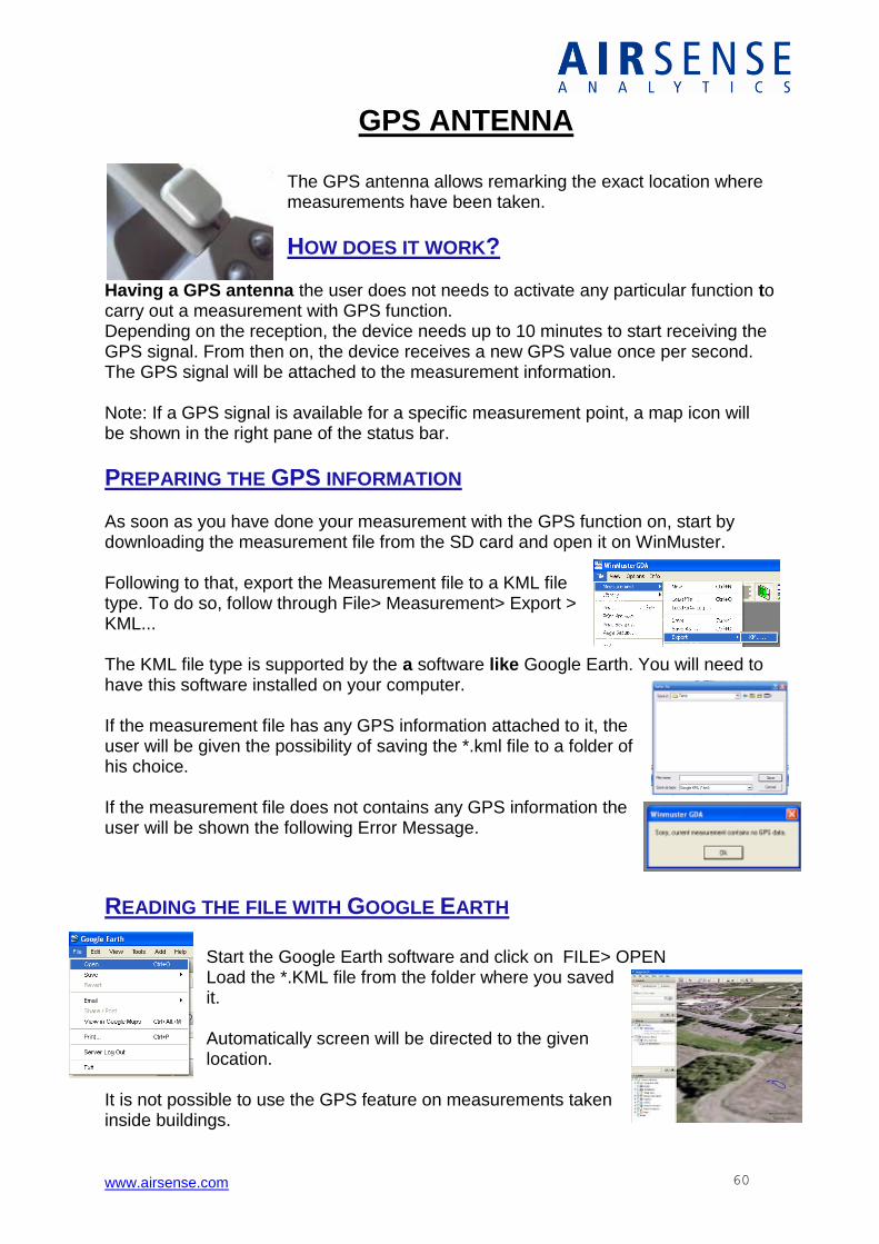
www.airsense.com 60
GPS ANTENNA
The GPS antenna allows remarking the exact location where measurements have been taken.
HOW DOES IT WORK?
Having a GPS antenna the user does not needs to activate any particular function to carry out a measurement with GPS function. Depending on the reception, the device needs up to 10 minutes to start receiving the GPS signal. From then on, the device receives a new GPS value once per second. The GPS signal will be attached to the measurement information. Note: If a GPS signal is available for a specific measurement point, a map icon will be shown in the right pane of the status bar.
PREPARING THE GPS INFORMATION As soon as you have done your measurement with the GPS function on, start by downloading the measurement file from the SD card and open it on WinMuster. Following to that, export the Measurement file to a KML file type. To do so, follow through File> Measurement> Export > KML... The KML file type is supported by the a software like Google Earth. You will need to have this software installed on your computer. If the measurement file has any GPS information attached to it, the user will be given the possibility of saving the *.kml file to a folder of his choice. If the measurement file does not contains any GPS information the user will be shown the following Error Message.
READING THE FILE WITH GOOGLE EARTH
Start the Google Earth software and click on FILE> OPEN Load the *.KML file from the folder where you saved it. Automatically screen will be directed to the given location.
It is not possible to use the GPS feature on measurements taken inside buildings.
www.airsense.com 61
GDA MAINTENANCE
www.airsense.com 62
SYSTEM CHECK On this procedure you will learn how to launch the different control tools to keep the device in the best measuring conditions. The available tools are: Flow Check Sensor Check Peak Height. Airsense recommends the User to do system checks on a regular base. The optimal situation would be to launch a system check tool before each important measurement. Because sometimes this is not possible, we recommend you to do a regular system check every two weeks
FLOW CHECK The Flow Check tool will check if the instrument is ready to carry out a measurement by analysing the current flow. This test will launch a sequence of stages that will calibrate the instrument. The sequence has the following order: Cleaning Stage Baseline Acquirement Test Signal Cleaning Stage. The Cleaning Stage will clean the device until the relative values drop to the recommended limits. If the instrument is kept clean, the cleaning stage is made within a few seconds. If that is not the case, this stage can last up to two minutes. During all stages you will be able to check on the device screen the advancement of the task through the task completion bars. As soon as a stage is completed a new bar will appear.
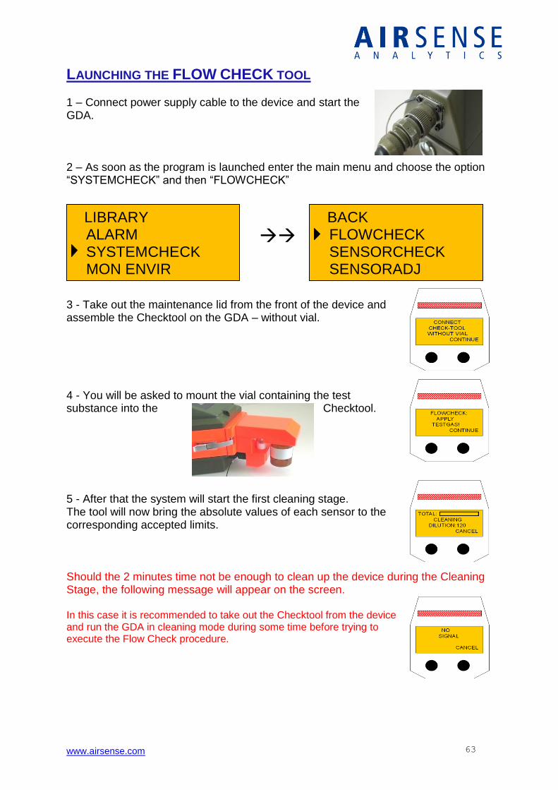
www.airsense.com 63
LIBRARY ALARM SYSTEMCHECK MON ENVIR MON SOURCE
BACK FLOWCHECK SENSORCHECK SENSORADJ
LAUNCHING THE FLOW CHECK TOOL 1 – Connect power supply cable to the device and start the GDA. 2 – As soon as the program is launched enter the main menu and choose the option “SYSTEMCHECK” and then “FLOWCHECK”
3 - Take out the maintenance lid from the front of the device and assemble the Checktool on the GDA – without vial. 4 - You will be asked to mount the vial containing the test substance into the Checktool.
5 - After that the system will start the first cleaning stage. The tool will now bring the absolute values of each sensor to the corresponding accepted limits. Should the 2 minutes time not be enough to clean up the device during the Cleaning Stage, the following message will appear on the screen. In this case it is recommended to take out the Checktool from the device and run the GDA in cleaning mode during some time before trying to execute the Flow Check procedure.
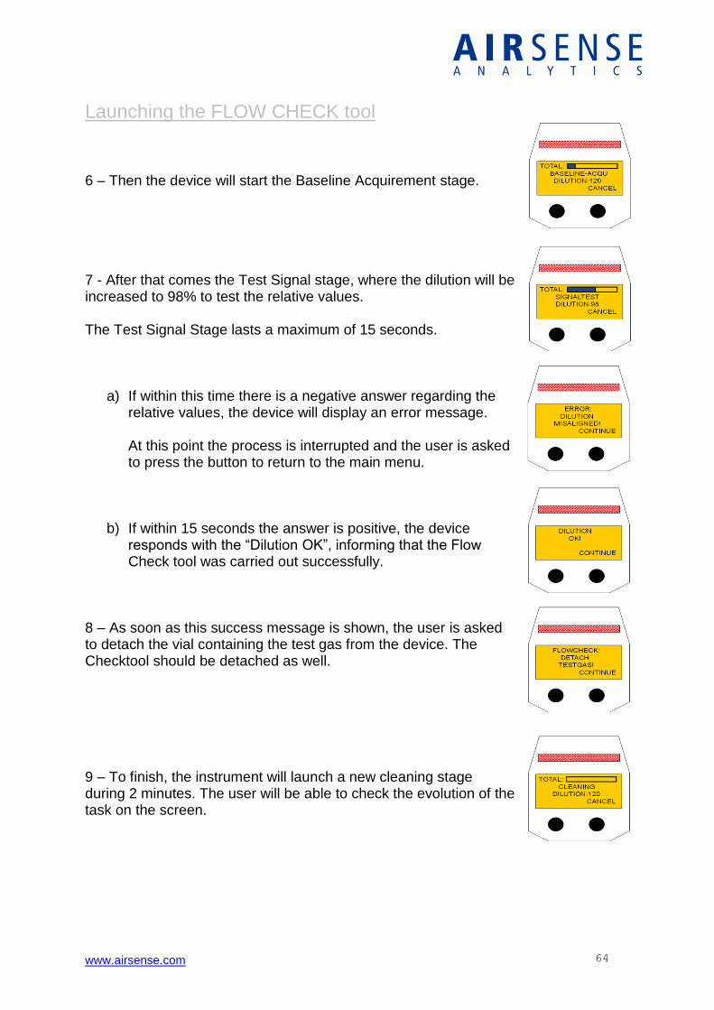
www.airsense.com 64
Launching the FLOW CHECK tool 6 – Then the device will start the Baseline Acquirement stage. 7 - After that comes the Test Signal stage, where the dilution will be increased to 98% to test the relative values. The Test Signal Stage lasts a maximum of 15 seconds.
a) If within this time there is a negative answer regarding the relative values, the device will display an error message. At this point the process is interrupted and the user is asked to press the button to return to the main menu.
b) If within 15 seconds the answer is positive, the device responds with the “Dilution OK”, informing that the Flow Check tool was carried out successfully.
8 – As soon as this success message is shown, the user is asked to detach the vial containing the test gas from the device. The Checktool should be detached as well. 9 – To finish, the instrument will launch a new cleaning stage during 2 minutes. The user will be able to check the evolution of the task on the screen.
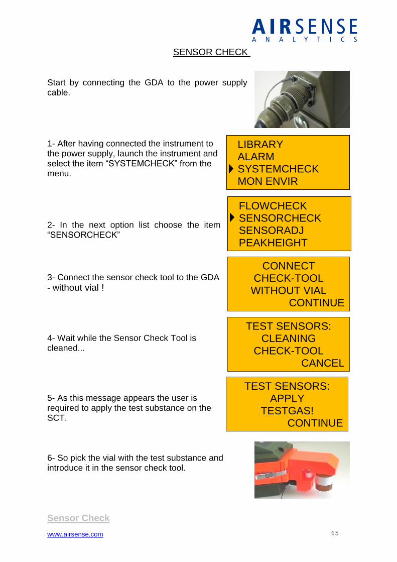
www.airsense.com 65
TEST SENSORS: CLEANING
CHECK-TOOL CANCEL
CONNECT CHECK-TOOL
WITHOUT VIAL CONTINUE
TEST SENSORS: APPLY
TESTGAS! CONTINUE
FLOWCHECK SENSORCHECK SENSORADJ PEAKHEIGHT
LIBRARY ALARM SYSTEMCHECK MON ENVIR
SENSOR CHECK Start by connecting the GDA to the power supply cable.
1- After having connected the instrument to the power supply, launch the instrument and select the item “SYSTEMCHECK” from the menu.
2- In the next option list choose the item “SENSORCHECK”
3- Connect the sensor check tool to the GDA
- without vial ! 4- Wait while the Sensor Check Tool is cleaned...
5- As this message appears the user is required to apply the test substance on the SCT. 6- So pick the vial with the test substance and introduce it in the sensor check tool.
Sensor Check
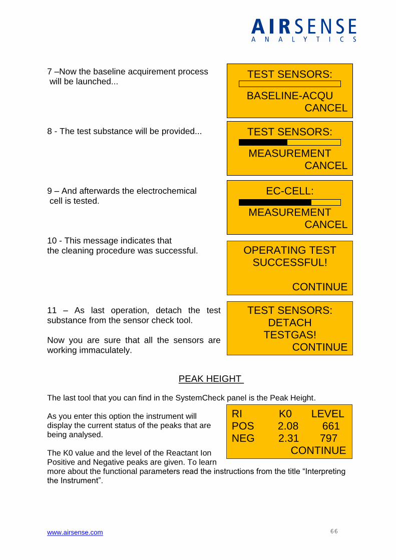
www.airsense.com 66
TEST SENSORS:
MEASUREMENT CANCEL
EC-CELL:
MEASUREMENT CANCEL
OPERATING TEST SUCCESSFUL!
CONTINUE
TEST SENSORS: DETACH
TESTGAS! CONTINUE
RI K0 LEVEL POS 2.08 661 NEG 2.31 797 CONTINUE
7 –Now the baseline acquirement process will be launched... 8 - The test substance will be provided... 9 – And afterwards the electrochemical cell is tested. 10 - This message indicates that the cleaning procedure was successful. 11 – As last operation, detach the test substance from the sensor check tool. Now you are sure that all the sensors are working immaculately.
PEAK HEIGHT The last tool that you can find in the SystemCheck panel is the Peak Height. As you enter this option the instrument will display the current status of the peaks that are being analysed. The K0 value and the level of the Reactant Ion Positive and Negative peaks are given. To learn more about the functional parameters read the instructions from the title “Interpreting the Instrument”.
TEST SENSORS:
BASELINE-ACQU CANCEL
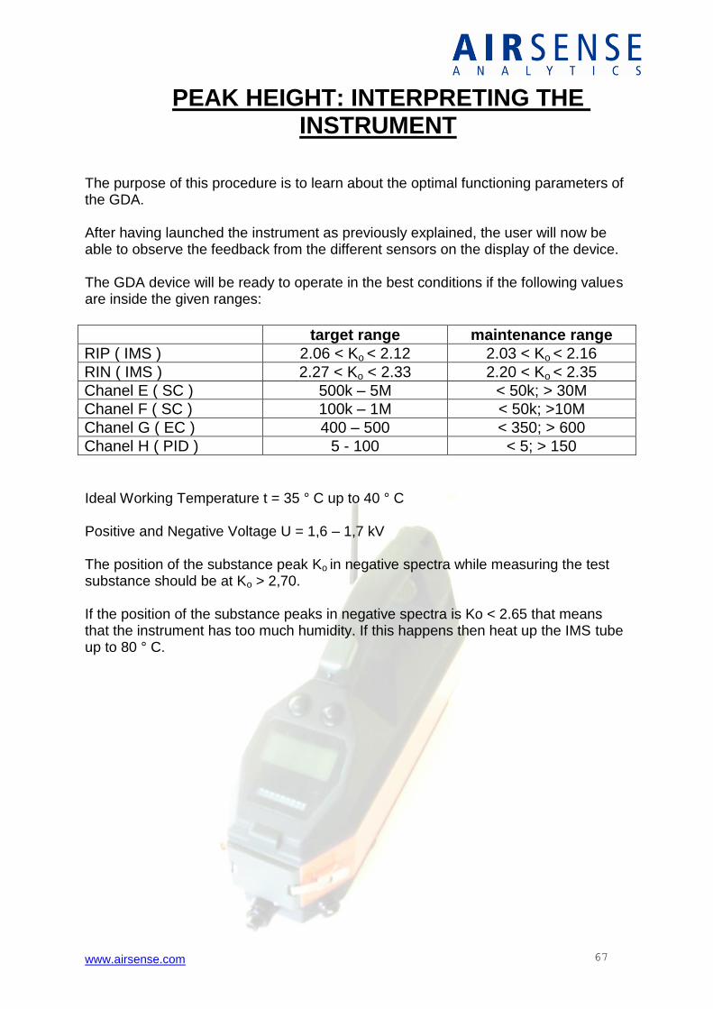
www.airsense.com 67
PEAK HEIGHT: INTERPRETING THE INSTRUMENT
The purpose of this procedure is to learn about the optimal functioning parameters of the GDA. After having launched the instrument as previously explained, the user will now be able to observe the feedback from the different sensors on the display of the device. The GDA device will be ready to operate in the best conditions if the following values are inside the given ranges:
target range maintenance range
RIP ( IMS ) 2.06 < Ko < 2.12 2.03 < Ko < 2.16
RIN ( IMS ) 2.27 < Ko < 2.33 2.20 < Ko < 2.35
Chanel E ( SC ) 500k – 5M < 50k; > 30M
Chanel F ( SC ) 100k – 1M < 50k; >10M
Chanel G ( EC ) 400 – 500 < 350; > 600
Chanel H ( PID ) 5 - 100 < 5; > 150
Ideal Working Temperature t = 35 ° C up to 40 ° C Positive and Negative Voltage U = 1,6 – 1,7 kV The position of the substance peak Ko in negative spectra while measuring the test substance should be at Ko > 2,70. If the position of the substance peaks in negative spectra is Ko < 2.65 that means that the instrument has too much humidity. If this happens then heat up the IMS tube up to 80 ° C.
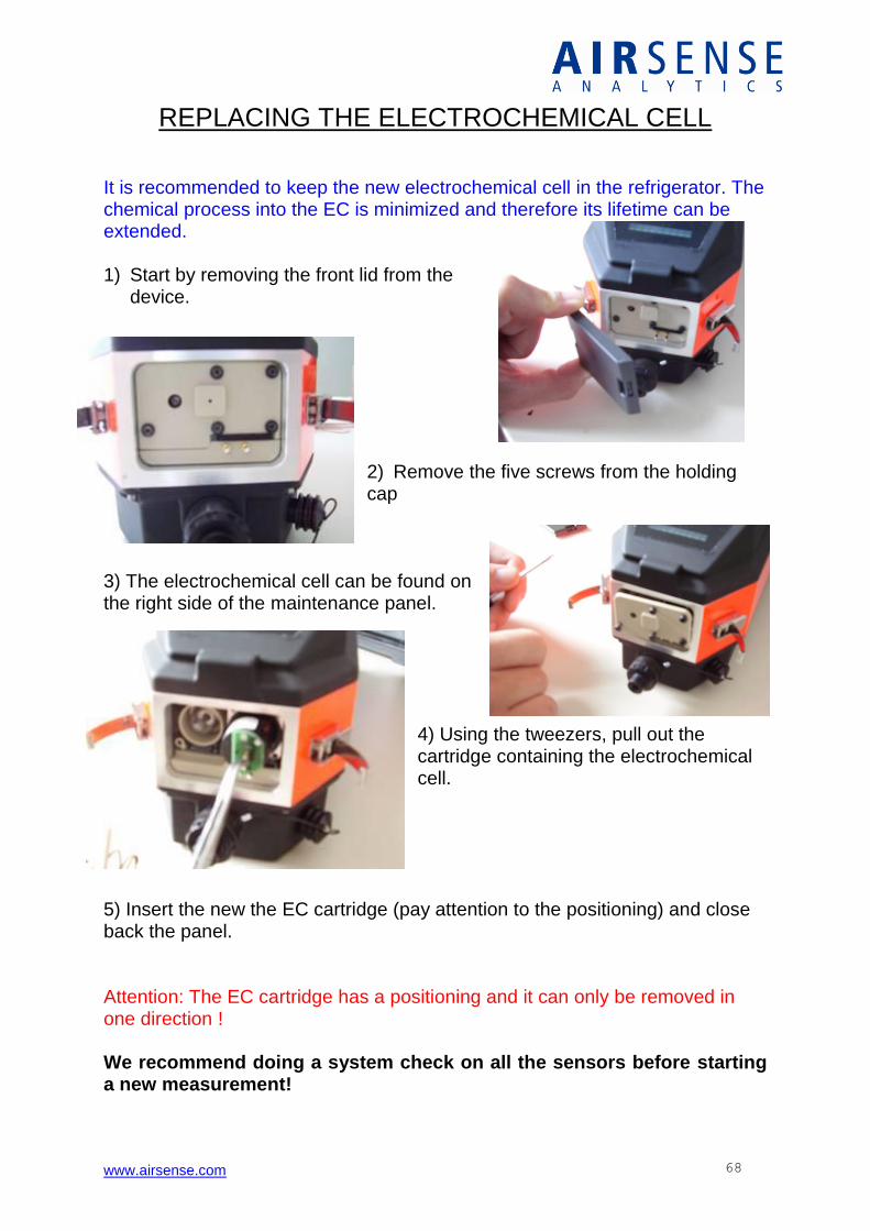
www.airsense.com 68
REPLACING THE ELECTROCHEMICAL CELL It is recommended to keep the new electrochemical cell in the refrigerator. The chemical process into the EC is minimized and therefore its lifetime can be extended. 1) Start by removing the front lid from the
device.
2) Remove the five screws from the holding cap
3) The electrochemical cell can be found on the right side of the maintenance panel.
4) Using the tweezers, pull out the cartridge containing the electrochemical cell.
5) Insert the new the EC cartridge (pay attention to the positioning) and close back the panel. Attention: The EC cartridge has a positioning and it can only be removed in one direction ! We recommend doing a system check on all the sensors before starting a new measurement!
www.airsense.com 69
FILTERS
The GDA is equipped with 2 filters: the “zero gas filter” and the “drying filter”. These filters have a different lifetime which is also very much dependable of the measuring conditions. The lifetime of the “zero gas filter” is mainly dependable of the measuring conditions. Using the device in environments where the air moisture rate is higher might reduce its cycle lifetime. You will know when to change this filter through the response of the System Check Tool. The “drying filter” has an operational time of about 500 hours. Since the operational time of this filter is also variable, the GDA has an internal counter clock that displays an automatic message saying “CHANGE FILTER” once this limit has been reached. The first step to take is to make a control with the System Check Tool. If the result of the spectrum is clean and the K0 values are in the normal region for the test substance, then you should ignore the warning message and reset the counter clock. If the System Check result show differences that means that the message is correct. On that case it is recommended to follow the instructions below in order to change filters and in the end to reset the internal counter clock. IF It happens that you changed the filters not for long time ago and you are being shown this automatic message, do a control with the System Check tool just for precaution, and if everything is ok, then just reset the internal counter clock
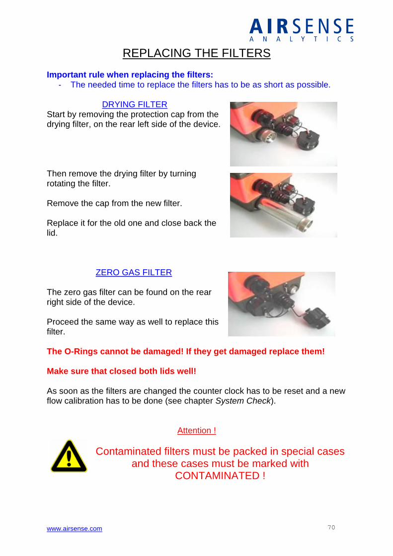
www.airsense.com 70
REPLACING THE FILTERS
Important rule when replacing the filters: - The needed time to replace the filters has to be as short as possible.
DRYING FILTER
Start by removing the protection cap from the drying filter, on the rear left side of the device. Then remove the drying filter by turning rotating the filter. Remove the cap from the new filter. Replace it for the old one and close back the lid.
ZERO GAS FILTER The zero gas filter can be found on the rear right side of the device. Proceed the same way as well to replace this filter. The O-Rings cannot be damaged! If they get damaged replace them! Make sure that closed both lids well! As soon as the filters are changed the counter clock has to be reset and a new flow calibration has to be done (see chapter System Check).
Attention !
Contaminated filters must be packed in special cases and these cases must be marked with
CONTAMINATED !
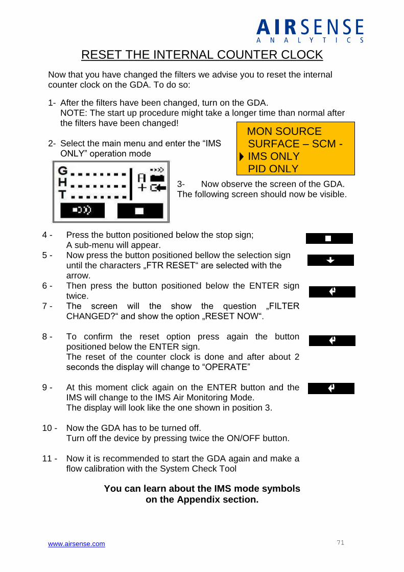
www.airsense.com 71
MON SOURCE SURFACE – SCM - IMS ONLY PID ONLY
RESET THE INTERNAL COUNTER CLOCK
Now that you have changed the filters we advise you to reset the internal counter clock on the GDA. To do so:
1- After the filters have been changed, turn on the GDA. NOTE: The start up procedure might take a longer time than normal after the filters have been changed!
2- Select the main menu and enter the “IMS ONLY” operation mode
3- Now observe the screen of the GDA. The following screen should now be visible.
4 - Press the button positioned below the stop sign; A sub-menu will appear.
5 - Now press the button positioned bellow the selection sign until the characters „FTR RESET“ are selected with the arrow.
6 - Then press the button positioned below the ENTER sign twice.
7 - The screen will the show the question „FILTER CHANGED?“ and show the option „RESET NOW“.
8 - To confirm the reset option press again the button positioned below the ENTER sign. The reset of the counter clock is done and after about 2 seconds the display will change to “OPERATE”
9 - At this moment click again on the ENTER button and the IMS will change to the IMS Air Monitoring Mode. The display will look like the one shown in position 3.
10 - Now the GDA has to be turned off. Turn off the device by pressing twice the ON/OFF button.
11 - Now it is recommended to start the GDA again and make a flow calibration with the System Check Tool
You can learn about the IMS mode symbols on the Appendix section.
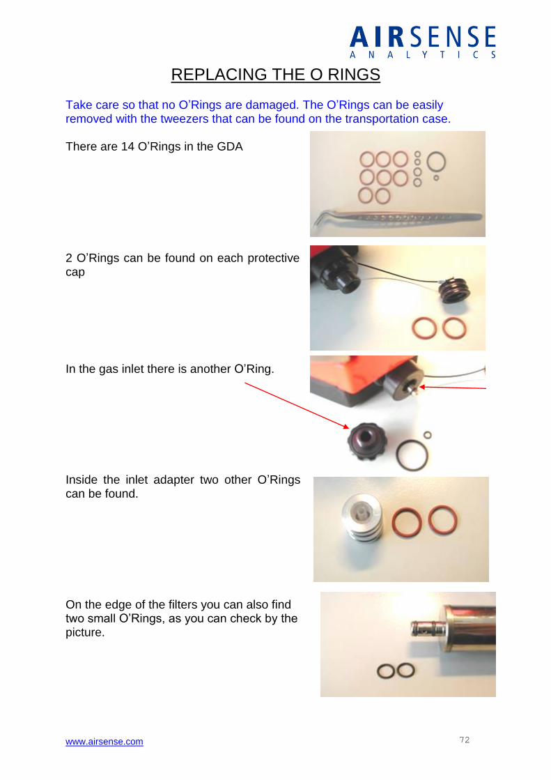
www.airsense.com 72
REPLACING THE O RINGS
Take care so that no O’Rings are damaged. The O’Rings can be easily removed with the tweezers that can be found on the transportation case.
There are 14 O’Rings in the GDA
2 O’Rings can be found on each protective cap In the gas inlet there is another O’Ring. Inside the inlet adapter two other O’Rings can be found. On the edge of the filters you can also find two small O’Rings, as you can check by the picture.
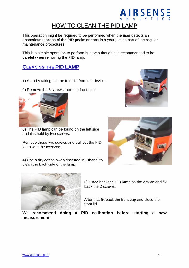
www.airsense.com 73
HOW TO CLEAN THE PID LAMP This operation might be required to be performed when the user detects an anomalous reaction of the PID peaks or once in a year just as part of the regular maintenance procedures. This is a simple operation to perform but even though it is recommended to be careful when removing the PID lamp.
CLEANING THE PID LAMP: 1) Start by taking out the front lid from the device. 2) Remove the 5 screws from the front cap.
3) The PID lamp can be found on the left side and it is held by two screws. Remove these two screws and pull out the PID lamp with the tweezers. 4) Use a dry cotton swab tinctured in Ethanol to clean the back side of the lamp.
5) Place back the PID lamp on the device and fix back the 2 screws. After that fix back the front cap and close the front lid.
We recommend doing a PID calibration before starting a new measurement!
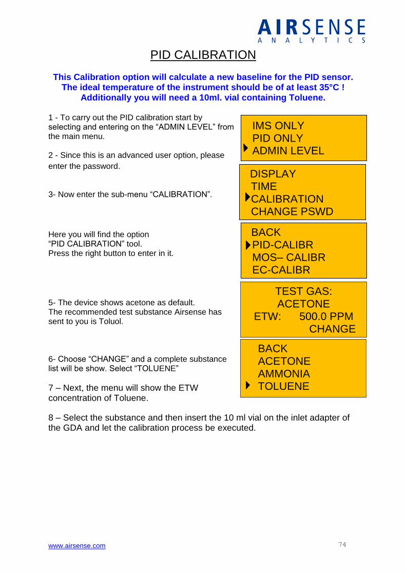
www.airsense.com 74
BACK PID-CALIBR MOS– CALIBR EC-CALIBR
IMS ONLY PID ONLY ADMIN LEVEL
DISPLAY TIME CALIBRATION CHANGE PSWD
TEST GAS: ACETONE
ETW: 500.0 PPM CHANGE
CANCEL
BACK ACETONE AMMONIA
TOLUENE
PID CALIBRATION This Calibration option will calculate a new baseline for the PID sensor.
The ideal temperature of the instrument should be of at least 35°C ! Additionally you will need a 10ml. vial containing Toluene.
1 - To carry out the PID calibration start by selecting and entering on the “ADMIN LEVEL” from the main menu. 2 - Since this is an advanced user option, please
enter the password. 3- Now enter the sub-menu “CALIBRATION”.
Here you will find the option “PID CALIBRATION” tool. Press the right button to enter in it.
5- The device shows acetone as default. The recommended test substance Airsense has sent to you is Toluol. 6- Choose “CHANGE” and a complete substance list will be show. Select “TOLUENE”
7 – Next, the menu will show the ETW concentration of Toluene.
8 – Select the substance and then insert the 10 ml vial on the inlet adapter of the GDA and let the calibration process be executed.
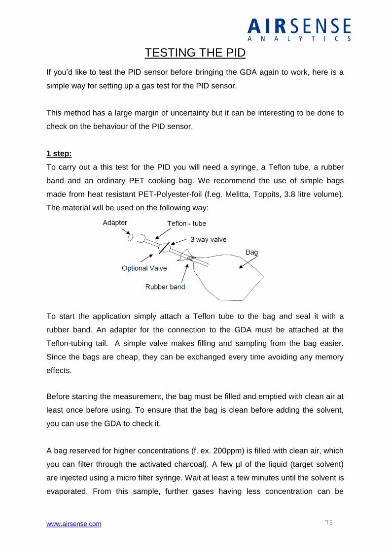
www.airsense.com 75
TESTING THE PID
If you’d like to test the PID sensor before bringing the GDA again to work, here is a
simple way for setting up a gas test for the PID sensor.
This method has a large margin of uncertainty but it can be interesting to be done to
check on the behaviour of the PID sensor.
1 step:
To carry out a this test for the PID you will need a syringe, a Teflon tube, a rubber
band and an ordinary PET cooking bag. We recommend the use of simple bags
made from heat resistant PET-Polyester-foil (f.eg. Melitta, Toppits, 3.8 litre volume).
The material will be used on the following way:
To start the application simply attach a Teflon tube to the bag and seal it with a
rubber band. An adapter for the connection to the GDA must be attached at the
Teflon-tubing tail. A simple valve makes filling and sampling from the bag easier.
Since the bags are cheap, they can be exchanged every time avoiding any memory
effects.
Before starting the measurement, the bag must be filled and emptied with clean air at
least once before using. To ensure that the bag is clean before adding the solvent,
you can use the GDA to check it.
A bag reserved for higher concentrations (f. ex. 200ppm) is filled with clean air, which
you can filter through the activated charcoal). A few µl of the liquid (target solvent)
are injected using a micro filter syringe. Wait at least a few minutes until the solvent is
evaporated. From this sample, further gases having less concentration can be
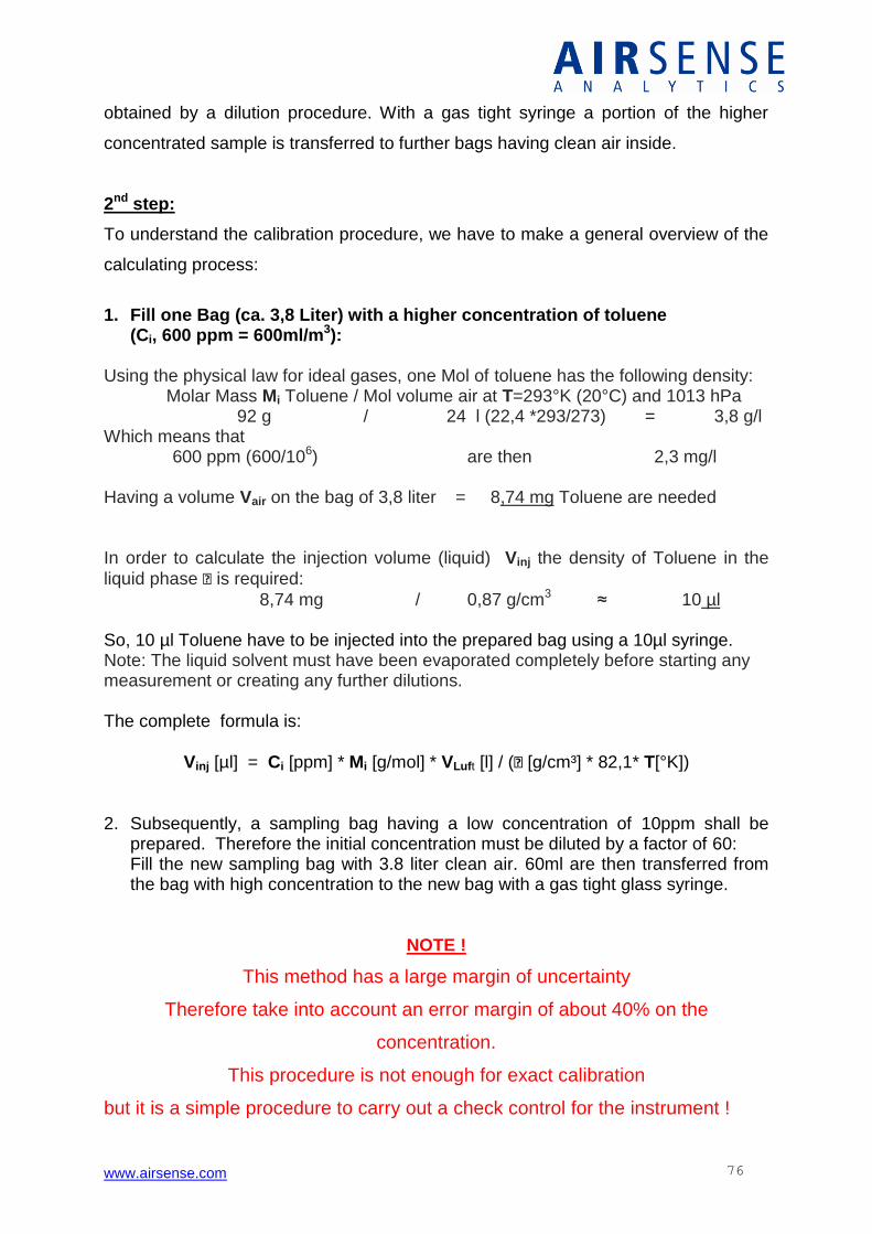
www.airsense.com 76
obtained by a dilution procedure. With a gas tight syringe a portion of the higher
concentrated sample is transferred to further bags having clean air inside.
2nd step:
To understand the calibration procedure, we have to make a general overview of the
calculating process:
1. Fill one Bag (ca. 3,8 Liter) with a higher concentration of toluene
(Ci, 600 ppm = 600ml/m3): Using the physical law for ideal gases, one Mol of toluene has the following density: Molar Mass Mi Toluene / Mol volume air at T=293°K (20°C) and 1013 hPa 92 g / 24 l (22,4 *293/273) = 3,8 g/l Which means that 600 ppm (600/106) are then 2,3 mg/l
Having a volume Vair on the bag of 3,8 liter = 8,74 mg Toluene are needed
In order to calculate the injection volume (liquid) Vinj the density of Toluene in the
liquid phase is required:
8,74 mg / 0,87 g/cm3 ≈ 10 µl
So, 10 µl Toluene have to be injected into the prepared bag using a 10µl syringe. Note: The liquid solvent must have been evaporated completely before starting any measurement or creating any further dilutions. The complete formula is:
Vinj [µl] = Ci [ppm] * Mi [g/mol] * VLuft [l] / ( [g/cm³] * 82,1* T[°K])
2. Subsequently, a sampling bag having a low concentration of 10ppm shall be
prepared. Therefore the initial concentration must be diluted by a factor of 60: Fill the new sampling bag with 3.8 liter clean air. 60ml are then transferred from the bag with high concentration to the new bag with a gas tight glass syringe.
NOTE !
This method has a large margin of uncertainty
Therefore take into account an error margin of about 40% on the
concentration.
This procedure is not enough for exact calibration
but it is a simple procedure to carry out a check control for the instrument !
www.airsense.com 77
APPENDIX
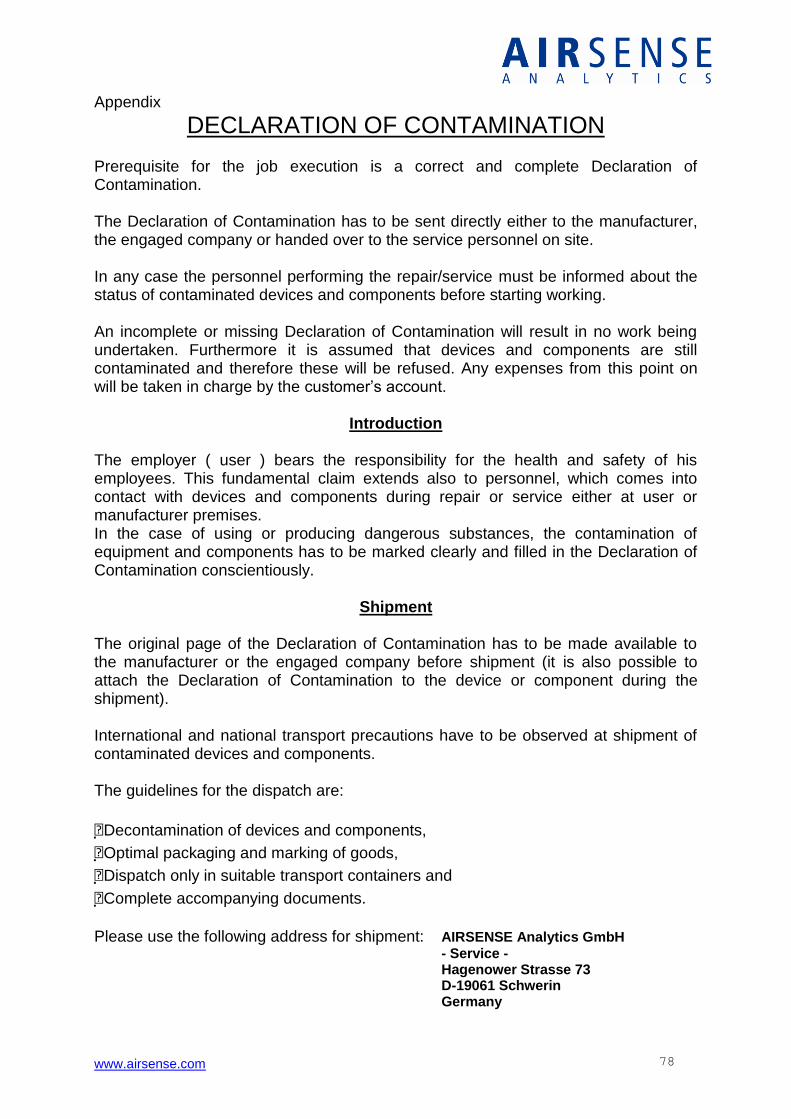
www.airsense.com 78
Appendix
DECLARATION OF CONTAMINATION
Prerequisite for the job execution is a correct and complete Declaration of Contamination. The Declaration of Contamination has to be sent directly either to the manufacturer, the engaged company or handed over to the service personnel on site. In any case the personnel performing the repair/service must be informed about the status of contaminated devices and components before starting working. An incomplete or missing Declaration of Contamination will result in no work being undertaken. Furthermore it is assumed that devices and components are still contaminated and therefore these will be refused. Any expenses from this point on will be taken in charge by the customer’s account.
Introduction
The employer ( user ) bears the responsibility for the health and safety of his employees. This fundamental claim extends also to personnel, which comes into contact with devices and components during repair or service either at user or manufacturer premises. In the case of using or producing dangerous substances, the contamination of equipment and components has to be marked clearly and filled in the Declaration of Contamination conscientiously.
Shipment The original page of the Declaration of Contamination has to be made available to the manufacturer or the engaged company before shipment (it is also possible to attach the Declaration of Contamination to the device or component during the shipment). International and national transport precautions have to be observed at shipment of contaminated devices and components. The guidelines for the dispatch are:
Decontamination of devices and components,
Optimal packaging and marking of goods,
Dispatch only in suitable transport containers and
Complete accompanying documents.
Please use the following address for shipment: AIRSENSE Analytics GmbH - Service - Hagenower Strasse 73 D-19061 Schwerin Germany
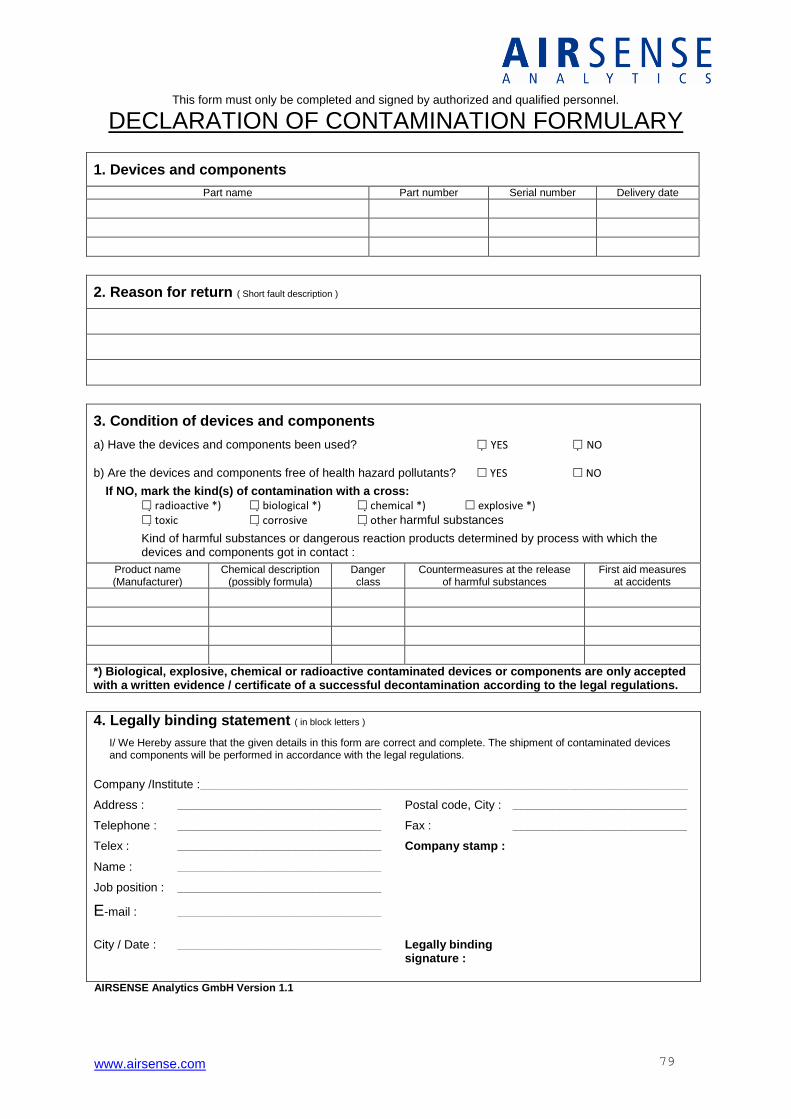
www.airsense.com 79
This form must only be completed and signed by authorized and qualified personnel.
DECLARATION OF CONTAMINATION FORMULARY
1. Devices and components
Part name Part number Serial number Delivery date
2. Reason for return ( Short fault description )
3. Condition of devices and components
a) Have the devices and components been used? YES NO b) Are the devices and components free of health hazard pollutants? YES NO
If NO, mark the kind(s) of contamination with a cross:
radioactive *) biological *) chemical *) explosive *) toxic corrosive other harmful substances
Kind of harmful substances or dangerous reaction products determined by process with which the devices and components got in contact :
Product name (Manufacturer)
Chemical description (possibly formula)
Danger class
Countermeasures at the release of harmful substances
First aid measures at accidents
*) Biological, explosive, chemical or radioactive contaminated devices or components are only accepted with a written evidence / certificate of a successful decontamination according to the legal regulations.
4. Legally binding statement ( in block letters )
I/ We Hereby assure that the given details in this form are correct and complete. The shipment of contaminated devices and components will be performed in accordance with the legal regulations.
Company /Institute :_____________________________________________________________________________________________________________________________________________________________________
Address : _____________________________________________________________________ Postal code, City : ___________________________________________________________
Telephone : _____________________________________________________________________ Fax : ___________________________________________________________
Telex : _____________________________________________________________________ Company stamp :
Name : _____________________________________________________________________
Job position : _____________________________________________________________________
E-mail : _____________________________________________________________________
City / Date : _____________________________________________________________________ Legally binding signature :
AIRSENSE Analytics GmbH Version 1.1
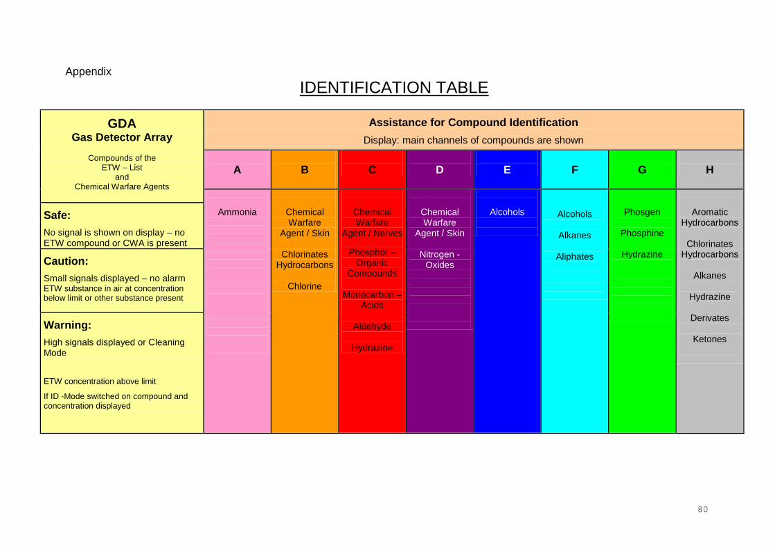
80
Appendix
IDENTIFICATION TABLE
GDA Gas Detector Array
Compounds of the
ETW – List and
Chemical Warfare Agents
Assistance for Compound Identification
Display: main channels of compounds are shown
A
B
C
D
E
F
G
H
Ammonia
Chemical Warfare
Agent / Skin
Chlorinates Hydrocarbons
Chlorine
Chemical Warfare
Agent / Nerves
Phosphor – Organic
Compounds
Monocarbon – Acids
Aldehyde
Hydrazine
Chemical Warfare
Agent / Skin
Nitrogen -Oxides
Alcohols
Alcohols
Alkanes
Aliphates
Phosgen
Phosphine
Hydrazine
Aromatic Hydrocarbons
Chlorinates
Hydrocarbons
Alkanes
Hydrazine
Derivates
Ketones
Safe:
No signal is shown on display – no ETW compound or CWA is present
Caution:
Small signals displayed – no alarm ETW substance in air at concentration below limit or other substance present
Warning:
High signals displayed or Cleaning Mode
ETW concentration above limit
If ID -Mode switched on compound and concentration displayed

81
Appendix
CHANNELS OF THE GDA 2
Channels of the Gas Detector Array 2
No. Compound Must No. Compound Must No. Compound Must
1 Acroleine C, H 18 Hydrogen fluoride B 35 S – Lost – CWA B, D
2 Formaldehyde A, C 19 Methanol C, E 36 Soman – CWA C
3 Hydrogen sulfide B, G 20 Methyl salicylate C, D 37 Tabun – CWA C, B
4 Hydrazine C, H, G, F
21 Nitrogen dioxide B 38 VX – CWA C
5 Acetone C, H 22 Phosgene B, G 39 Lewisit – CWA D
6 Acrylonitrile C 23 Phosphine F, G 40 DIMP – CWA Simulant
C
7 Ammonia A 24 Sulfur dioxide D 41 DMMP – CWA Simulant
C
8 Benzene / Styrole / Tuloene
H 25 Tetrachloroethylene D, H 42 DPM – CWA Simulant
C, D
9 Hydrogen cyanide B 26 Toluene diisocyanate D 43
10 Chlorine B, G 27 Trichloroethylene B, C, H
44
11 Chlorobenzene H, F 28 1,1,1 – Trichloroethane B, H 45
12
Chlorocyane B 29 1,1,2 – Trichloroethane B 46
13 Carbon dioxide D 30 Vinyl chloride H 47
14 Carbon disulfide D, H 31 Cleaner A containing Ammonia
C, D 48
15 Acetic acid C, D 32 Cleaner C containing Chlorine
B 49
16 Ethanol C 33 Cleaner W containing Wax
C 50
17 Hexane H, F 34 Sarin – CWA C 51
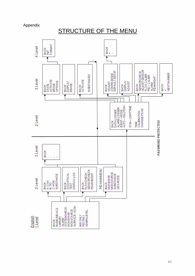
82
Appendix
STRUCTURE OF THE MENU

83
ERROR MESSAGES Below we will be listing the most common error messages from the GDA during the various stages and our recommendations to solve the problem.
Process Time
Error / Warning
Display Cause / Solution
Start Up Warning Warning: Check Calibration! Alarm from the IMS Internal counter clock! See section: Reset internal counter clock.
ERROR A 031 - CHANGE FILTER Cycle filter operation time overflow. Replace the cycle filter and reset filter operation time (SA 31 - 201_Change filter).
ERROR E 070 - CHECK BATTERY
Operating voltage is too low. Replace battery pack immediately or check external power supply. If error still occurs, please inform maintenance.
ERROR E 071 - CHECK BATTERY Operating voltage is too high. Check external power supply. Operate GDA with battery, if error still occurs, please inform maintenance.
ERROR E 140 - OPEN GAS IN-/OUTLET E 141 - OPEN GAS IN-/OUTLET
Sample flow is too low. Sample flow is too high. Open air inlet and air outlet. Check dust filter. If blocked, clean the respective area. If the error still occurs, replace the zero gas filter and reset filter operation time (SA 31 - 201_Change filter). If the error occurs repeatedly, please inform maintenance.
ERROR ERROR: CHECK VALVES! Electro-Chemical cell valve is not well positioned. Turn the GDA Off and On. Should the Error comes up again; it is possible that the Valve is defective. Please inform Airsense Support service.
WARNING WARNING: CAPS REMOVED?
Incoming flow insufficient. The user might have forgotten to remove caps from in/outlets. Other possible causes: Gas Flow sensor or pump may be defective. Should the problem persist, contact Airsense Support service.
ERROR ERROR: GAS FLOW IN- OUTLET CLOSED?
Incoming flow insufficient. Incoming flow insufficient. The user might have forgotten to remove caps from in/outlets. Other possible causes: Gas Flow sensor or pump may be defective. Should the problem persist, please contact Airsense Support service.
WARNING WARNING: BATTERYSTATE LOW!
Battery is getting without charge. Use the spare battery and put the first to charge.
WARNING WARNING: BATTERY REPORTS ERROR!
Battery error. Turn GDA off and on. Should the Error persist, try using the spare battery or using an external power source. Charge the battery and test it. Should the error persist, battery is possibly defective – contact Airsense Support Service.
WARNING WARNING: MEMORY xx PERC FULL CA yy H zz MIN LEFT!
Data Logger has surpassed 50% of its saving capacity. Should the free capacity be enough to do a new measurement click OK to continue. If not, evaluate the possibility of erasing files from the data logger or change the SD card. Do not forget to off turn the device before removing the SD card.
WARNING WARNING: ALARM LOGGER xx PERC FULL!
Data Logger is reaching full status. Delete information from the Data Logger or change the SD card. Do not forget to turn off the device before removing the SD card.
WARNING WARNING: DAMAGED FAT! CHANGE CARD!
The FAT formating from the SD card is defective. Change the SD card or work without Data Logger (WinMuster assisted). Before changing the SD card, turn off the device. ,
WARNING WARNING: AUDIBLE ALARM OFF! Alarm has been manually turned off. To turn Alarm back on, enter the main menu, choose option “Alarm” and “Acoustic”
WARNING WARNING: HEATER TEMP MEMBRANE LOW!
Membrane Heater is not functioning correctly. Turn off and on the device and should the error persist, contact Airsense Support service.
WARNING RI K0 LEVEL Humidity or impurities inside the IMS or defective IMS. Heat up the IMS tube, change filters, turn off and start again the device. Should the problem persist, please contact Airsense Support service.
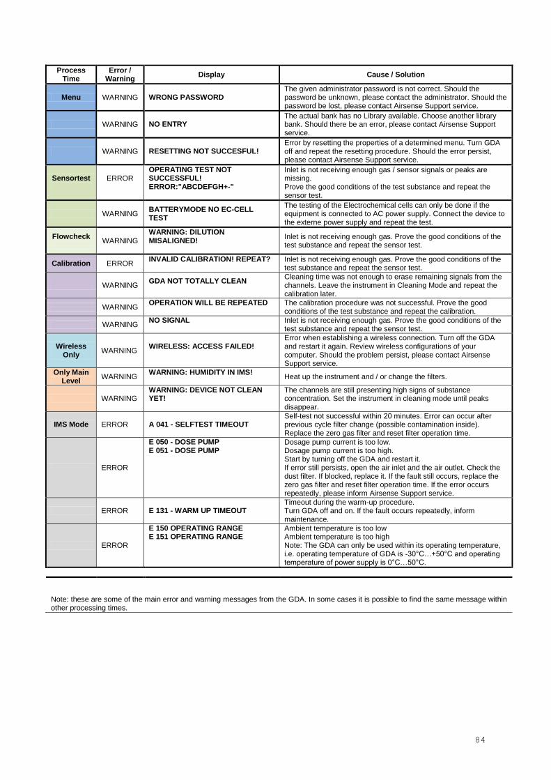
84
Process Time
Error / Warning
Display Cause / Solution
Menu WARNING WRONG PASSWORD The given administrator password is not correct. Should the password be unknown, please contact the administrator. Should the password be lost, please contact Airsense Support service.
WARNING NO ENTRY The actual bank has no Library available. Choose another library bank. Should there be an error, please contact Airsense Support service.
WARNING RESETTING NOT SUCCESFUL! Error by resetting the properties of a determined menu. Turn GDA off and repeat the resetting procedure. Should the error persist, please contact Airsense Support service.
Sensortest
ERROR
OPERATING TEST NOT SUCCESSFUL! ERROR:"ABCDEFGH+-"
Inlet is not receiving enough gas / sensor signals or peaks are missing. Prove the good conditions of the test substance and repeat the sensor test.
WARNING BATTERYMODE NO EC-CELL TEST
The testing of the Electrochemical cells can only be done if the equipment is connected to AC power supply. Connect the device to the externe power supply and repeat the test.
Flowcheck
WARNING WARNING: DILUTION MISALIGNED!
Inlet is not receiving enough gas. Prove the good conditions of the test substance and repeat the sensor test.
Calibration ERROR INVALID CALIBRATION! REPEAT?
Inlet is not receiving enough gas. Prove the good conditions of the test substance and repeat the sensor test.
WARNING GDA NOT TOTALLY CLEAN
Cleaning time was not enough to erase remaining signals from the channels. Leave the instrument in Cleaning Mode and repeat the calibration later.
WARNING OPERATION WILL BE REPEATED
The calibration procedure was not successful. Prove the good conditions of the test substance and repeat the calibration.
WARNING NO SIGNAL
Inlet is not receiving enough gas. Prove the good conditions of the test substance and repeat the sensor test.
Wireless Only
WARNING WIRELESS: ACCESS FAILED!
Error when establishing a wireless connection. Turn off the GDA and restart it again. Review wireless configurations of your computer. Should the problem persist, please contact Airsense Support service.
Only Main Level
WARNING WARNING: HUMIDITY IN IMS!
Heat up the instrument and / or change the filters.
WARNING WARNING: DEVICE NOT CLEAN YET!
The channels are still presenting high signs of substance concentration. Set the instrument in cleaning mode until peaks disappear.
IMS Mode ERROR A 041 - SELFTEST TIMEOUT Self-test not successful within 20 minutes. Error can occur after previous cycle filter change (possible contamination inside). Replace the zero gas filter and reset filter operation time.
ERROR
E 050 - DOSE PUMP E 051 - DOSE PUMP
Dosage pump current is too low. Dosage pump current is too high. Start by turning off the GDA and restart it. If error still persists, open the air inlet and the air outlet. Check the dust filter. If blocked, replace it. If the fault still occurs, replace the zero gas filter and reset filter operation time. If the error occurs repeatedly, please inform Airsense Support service.
ERROR E 131 - WARM UP TIMEOUT Timeout during the warm-up procedure. Turn GDA off and on. If the fault occurs repeatedly, inform maintenance.
ERROR
E 150 OPERATING RANGE E 151 OPERATING RANGE
Ambient temperature is too low Ambient temperature is too high Note: The GDA can only be used within its operating temperature, i.e. operating temperature of GDA is -30°C…+50°C and operating temperature of power supply is 0°C…50°C.
Note: these are some of the main error and warning messages from the GDA. In some cases it is possible to find the same message within other processing times.
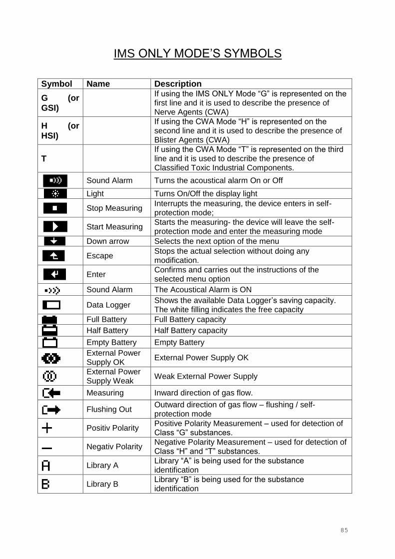
85
IMS ONLY MODE’S SYMBOLS
Symbol Name Description
G (or GSI)
If using the IMS ONLY Mode “G” is represented on the first line and it is used to describe the presence of Nerve Agents (CWA)
H (or HSI)
If using the CWA Mode “H” is represented on the second line and it is used to describe the presence of Blister Agents (CWA)
T If using the CWA Mode “T” is represented on the third line and it is used to describe the presence of Classified Toxic Industrial Components.
Sound Alarm Turns the acoustical alarm On or Off
Light Turns On/Off the display light
Stop Measuring Interrupts the measuring, the device enters in self-protection mode;
Start Measuring Starts the measuring- the device will leave the self-protection mode and enter the measuring mode
Down arrow Selects the next option of the menu
Escape Stops the actual selection without doing any modification.
Enter Confirms and carries out the instructions of the selected menu option
Sound Alarm The Acoustical Alarm is ON
Data Logger Shows the available Data Logger’s saving capacity. The white filling indicates the free capacity
Full Battery Full Battery capacity
Half Battery Half Battery capacity
Empty Battery Empty Battery
External Power Supply OK
External Power Supply OK
External Power Supply Weak
Weak External Power Supply
Measuring Inward direction of gas flow.
Flushing Out
Outward direction of gas flow – flushing / self-protection mode
Positiv Polarity Positive Polarity Measurement – used for detection of Class “G” substances.
Negativ Polarity Negative Polarity Measurement – used for detection of Class “H” and “T” substances.
Library A Library “A” is being used for the substance identification
Library B Library “B” is being used for the substance identification
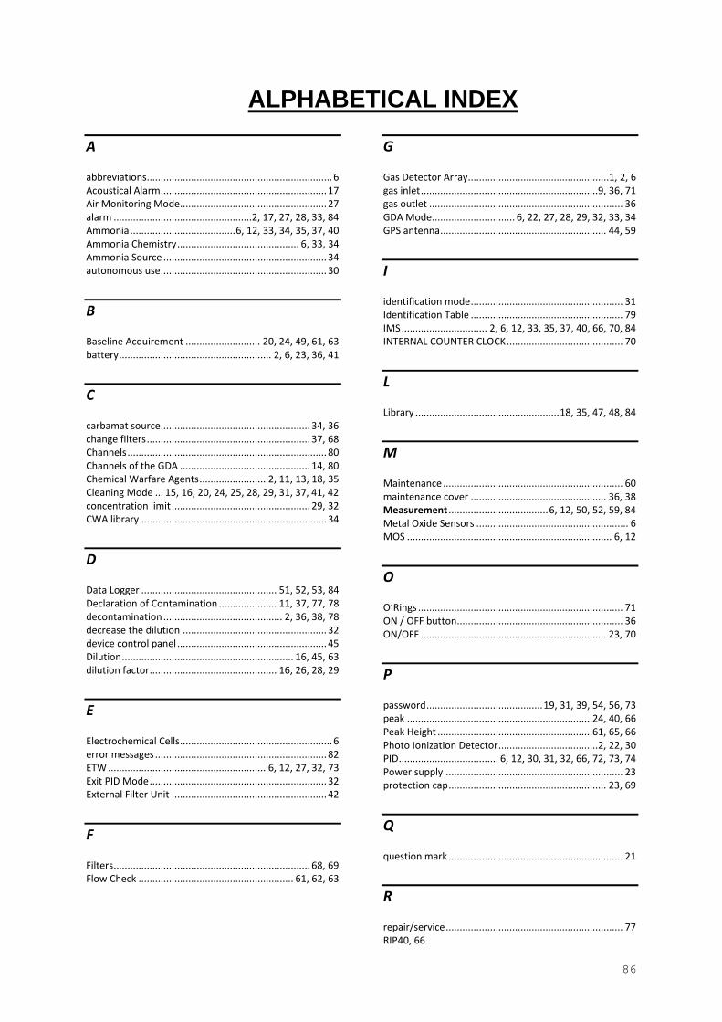
86
ALPHABETICAL INDEX
A
abbreviations................................................................... 6 Acoustical Alarm ............................................................ 17 Air Monitoring Mode..................................................... 27 alarm ..................................................2, 17, 27, 28, 33, 84 Ammonia ...................................... 6, 12, 33, 34, 35, 37, 40 Ammonia Chemistry ............................................ 6, 33, 34 Ammonia Source ........................................................... 34 autonomous use ............................................................ 30
B
Baseline Acquirement ........................... 20, 24, 49, 61, 63 battery ....................................................... 2, 6, 23, 36, 41
C
carbamat source...................................................... 34, 36 change filters ........................................................... 37, 68 Channels ........................................................................ 80 Channels of the GDA ............................................... 14, 80 Chemical Warfare Agents ........................ 2, 11, 13, 18, 35 Cleaning Mode ... 15, 16, 20, 24, 25, 28, 29, 31, 37, 41, 42 concentration limit .................................................. 29, 32 CWA library ................................................................... 34
D
Data Logger ................................................. 51, 52, 53, 84 Declaration of Contamination ..................... 11, 37, 77, 78 decontamination ........................................... 2, 36, 38, 78 decrease the dilution .................................................... 32 device control panel ...................................................... 45 Dilution .............................................................. 16, 45, 63 dilution factor .............................................. 16, 26, 28, 29
E
Electrochemical Cells ....................................................... 6 error messages .............................................................. 82 ETW ......................................................... 6, 12, 27, 32, 73 Exit PID Mode ................................................................ 32 External Filter Unit ........................................................ 42
F
Filters ....................................................................... 68, 69 Flow Check ........................................................ 61, 62, 63
G
Gas Detector Array...................................................1, 2, 6 gas inlet ................................................................9, 36, 71 gas outlet ...................................................................... 36 GDA Mode.............................. 6, 22, 27, 28, 29, 32, 33, 34 GPS antenna ............................................................ 44, 59
I
identification mode ....................................................... 31 Identification Table ....................................................... 79 IMS ............................... 2, 6, 12, 33, 35, 37, 40, 66, 70, 84 INTERNAL COUNTER CLOCK .......................................... 70
L
Library .................................................... 18, 35, 47, 48, 84
M
Maintenance ................................................................. 60 maintenance cover ................................................. 36, 38 Measurement .................................... 6, 12, 50, 52, 59, 84 Metal Oxide Sensors ....................................................... 6 MOS .......................................................................... 6, 12
O
O’Rings .......................................................................... 71 ON / OFF button............................................................ 36 ON/OFF ................................................................... 23, 70
P
password .......................................... 19, 31, 39, 54, 56, 73 peak ...................................................................24, 40, 66 Peak Height ........................................................61, 65, 66 Photo Ionization Detector ....................................2, 22, 30 PID .................................... 6, 12, 30, 31, 32, 66, 72, 73, 74 Power supply ................................................................ 23 protection cap ......................................................... 23, 69
Q
question mark ............................................................... 21
R
repair/service ................................................................ 77 RIP 40, 66
87
RS 232 plug .................................................................... 36
S
SCM Tool ....................................................................... 38 self-protection ............................................. 20, 21, 31, 84 Sensor Check ............................................... 40, 61, 64, 65 Set up ...................................................................... 33, 34 Software ................................................ 32, 40, 43, 49, 53 Sound Alarm .................................................................. 29 SOURCE MONITORING MODE ....................................... 28 Starting the device .................................................. 23, 26 Support Holder .......................................................... 6, 55 Surface Contamination Tool .......................................... 38 Symbols ................................................................... 44, 45 System Check .......................................................... 37, 61
T
target substance ............................................................ 31 Toxic Industrial Chemicals ................................... 2, 13, 18 Turn the GDA off ........................................................... 41
turn the GDA on ............................................................ 29 Turn the GDA on ........................................................... 23
U
Uploading a Library ................................................. 47, 48
W
WARNINGS ...........................................................9, 10, 11 Water Chemistry ..................................................6, 23, 33 WinMuster ... 30, 32, 37, 39, 43, 44, 45, 46, 47, 48, 49, 51,
56, 59 Wireless antenna .......................................................... 56
Z
zero gas .................................................... 6, 36, 37, 68, 69 zero point process ........................................................ 20