Embed Size (px)
Citation preview
IMPORTANTREAD ALL OF THE FOLLOWINGWARNINGS AND STATEMENTS
BEFORE READING THEINSTALLATION INSTRUCTIONS
The installation must conform to the requirements ofthe authority having jurisdiction or, in the absence ofsuch requirements, to the National Fuel Gas Code,ANSI Z223.1-latest edition. The installation must alsoconform to the additional requirements in this Slant/FinInstruction Book.
In addition where required by the authority having juris-diction, the installation must conform to AmericanSociety of Mechanical Engineers Safety Code forControls and Safety Devices for Automatically FiredBoilers, No. CSD-1.
WARNINGThis boiler, gas piping and accessories must beinstalled, connected, serviced and repaired by atrained, experienced service technician, familiar with allprecautions required for gas-fired equipment andlicensed or otherwise qualified, in compliance with theauthority having jurisdiction.
WARNINGThe venting system of this boiler is under positive pressure.Leakage from this system can be hazardous and if not avoidedcan result in death or serious injury. In addition to the recom-mendations within this manual and the User’s InformationManual, the venting system, from the flue collector to the out-door discharge, must be carefully checked annually by a quali-fied service agency.
This manual must be left with owner and should behung on or adjacent to the boiler for reference.
INSTALLATION AND OPERATING INSTRUCTIONS
Printed in U.S.A. 810 Part No. 83-5736 Publication No. J-40 Rev. D
Heating Contractor
Address
Phone Number
Boiler Model Number
Boiler Serial Number
Installation Date
DIRECT-VENT SEALED COMBUSTION CONDENSING BOILERHOT WATER MODEL J-390CGAS-FIRED BOILER FOR NATURAL GAS
TABLE OF CONTENTS
Boiler Dimensions and Rating ....................................................2Identification of Parts ..................................................................3Installation Requirements ...........................................................4Contamination Prevention...........................................................5Venting Application .....................................................................5Boiler Room Air Supply and Ventilation......................................5Flue gas Venting Requirements..................................................6Additional Installation Requirements for Massachusetts ............6Vent Material ..............................................................................6Air Intake Material ......................................................................6Vent and Air Intake Restrictions .................................................7Non-Direct Vent Installation ........................................................8Sidewall Venting, Non-Direct Vent ..............................................8Vent Termination Location and Clearance..................................8Non-Direct Vent Vertical Venting .................................................8Direct Vent Installation ................................................................8Sidewall Venting, Direct Vent ......................................................8Vent/Air Intake Termination Installation.....................................14Direct Vent, Venting and Air Intake through a Roof ..................15Venting and Air Intake Regular Inspection ...............................16Condensate Removal System ..................................................16Gas Piping ................................................................................16Electrical Wiring ........................................................................17Wiring Diagram.........................................................................18Single and Multi Zoning............................................................21Water Piping .............................................................................24Operating Instructions...............................................................30Boiler Control Display ...............................................................30Boiler Control ............................................................................30Sequence of Operation.............................................................36Gas Input Rate Adjustment ......................................................37Safety Check ...........................................................................38Care and Maintenance .............................................................41General Troubleshooting Guide ................................................42
REAR VIEW SIDE VIEW FRONT VIEW
TOP VIEW
9 5/8
25
WATER RETURN1 1/4" NPT (MALE)
GAS PIPE3/4" NPT
5 1/8
16 3/8
3 5/8
5 5/8CONDENSATE DRAIN - 3/4" DIA
4 1/44" AIR INTAKE CONNECTION
(5 3/4)
26
52
23 5/8
4 1/4
52 5/8
9 5/8
5 1/2
3 7/8 (21 1/8)4" VENT CONNECTION
WATER SUPPLY1 1/4" NPT (MALE)46 7/8
13 1/2
(7/8)
Jaguar Model J-390C2
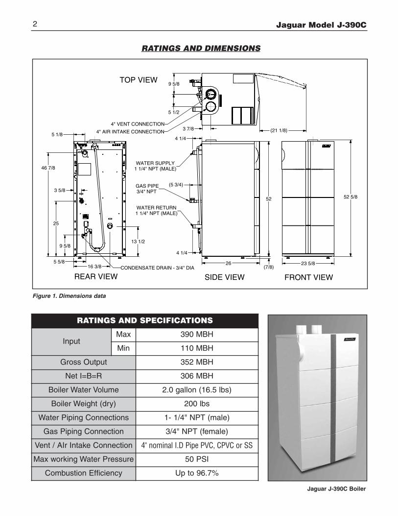
RATINGS AND DIMENSIONS
Figure 1. Dimensions data
Jaguar J-390C Boiler
RATINGS AND SPECIFICATIONS
InputMax 390 MBH
Min 110 MBH
Gross Output 352 MBH
Net I=B=R 306 MBH
Boiler Water Volume 2.0 gallon (16.5 lbs)
Boiler Weight (dry) 200 lbs
Water Piping Connections 1- 1/4" NPT (male)
Gas Piping Connection 3/4" NPT (female)
Vent / AIr Intake Connection 4" nominal I.D Pipe PVC, CPVC or SS
Max working Water Pressure 50 PSI
Combustion Efficiency Up to 96.7%
Jaguar Model J-390C 3
BOILER CONTROL
FIELD WIRING TERMINALS (24V)
FIELD WIRING TERMINALS (120V)
GAS VALVE
TRANFORMER
4" AIR INTAKE CONNECTION
4" VENT CONNECTION
SPARK ELECTRODE(IGNITER)
HEAT EXCHANGER
VENTURI
COMBUSTIONBLOWER
WINDOW(SIGHT GLASS)
FLUE PIPE
FLUE SENSOR
GAS SUPPLYVALVE
WATER SUPPLY
WATER RETURN
BOILER CONDENSATE TRAP
WATER RETURN SENSOR
WATER SUPPLY SENSOR ANDWATER HIGH LIMIT FLUE SAMPLE
PORT
GAS VALVE
CONTROL BOARD COVER
CONTROL PANEL
FLUE SAMPLEPORT
HEAT EXCHANGER ENCLOSUREFRONT COVER
CONTROL PANEL DOOR
FIELD WIRING BX CONNECTORS
FRONT (INTERIOR) RIGHT SIDE (INTERIOR)
3" MIN
VENTING CONDENSATE TRAP
SEDIMENT TRAP(REQUIET)
INSTALL MANUAL MAINSHUTOFF VALVE 5' ABOVE FLOOR, WHEN RQUIRET BY LOCAL CODE
HEAT EXCHANGERENCLOSURE FRONTCOVER LATCH
HEAT EXCHANGERENCLOSURE FRONTCOVER LATCH
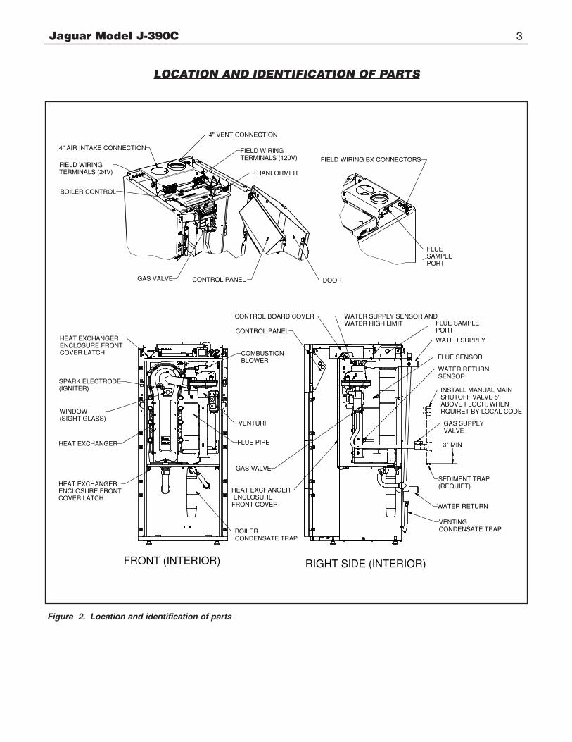
LOCATION AND IDENTIFICATION OF PARTS
Figure 2. Location and identification of parts
Jaguar Model J-390C4
The installation must conform to the requirements of theauthority having jurisdiction or, in the absence of suchrequirements, to the National Fuel Gas Code, ANSI Z223.1-latest edition.
This installation must also conform to the additional require-ments in this Slant/Fin Instruction Book.
BOILER LOCATIONProvide a level, solid foundation for the boiler. Locationshould be as near as possible to chimney or outside wall sothat the flue pipe from boiler is short and direct. (See para-graph heading “Vent Termination Location and Clearance” onpage 8.) The location should also be such that all boilercomponents are protected from water (dripping, spraying,rain, etc.) during appliance operation and service (circulatorreplacement, control replacement, etc.).
BOILER FOUNDATION A. Provide a solid, level foundation, capable of supporting the
weight of the boiler filled with water, and extending at least2" past the jacket on all sides. See dimensions of boilers,page 2.
B. Boiler can be installed on both combustible and non-combustible floors, but must NOT be installed on or above carpeting.
C. If boiler is to be located over buried conduit containingelectric wires or telephone cables, consult local codes orthe National Board of Fire Underwriters for specificrequirements.
MINIMUM CLEARANCES FROM COMBUSTIBLE CONSTRUCTIONS
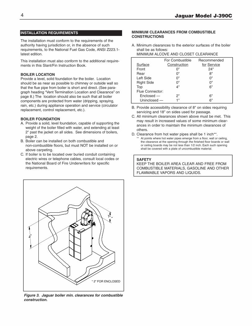
A. Minimum clearances to the exterior surfaces of the boilershall be as follows:MINIMUM ALCOVE AND CLOSET CLEARANCE
For Combustible RecommendedSurface Construction for ServiceFront 0" 24"Rear 0" 8"Left Side 0" 0"Right Side 0" 0"Top 4" 6"Flue Connector:Enclosed — 2" 6"Uninclosed — 1" 6"
B. Provide accessibility clearance of 8" on sides requiringservicing and 18" on sides used for passage.
C. All minimum clearances shown above must be met. Thismay result in increased values of some minimum clear-ances in order to maintain the minimum clearances ofothers.
D. Clearance from hot water pipes shall be 1 inch**.** At points where hot water pipes emerge from a floor, wall or ceiling,
the clearance at the opening through the finished floor boards or wallor ceiling boards may be not less than 1/2 inch. Each such openingshall be covered with a plate of uncombustible material.
Figure 3. Jaguar boiler min. clearances for combustibleconstruction.
INSTALLATION REQUIREMENTS
* 2" FOR ENCLOSED
SAFETYKEEP THE BOILER AREA CLEAR AND FREE FROMCOMBUSTIBLE MATERIALS, GASOLINE AND OTHERFLAMMABLE VAPORS AND LIQUIDS.
CONTAMINATION PREVENTION
The combustion air supply must not be susceptible to contami-nation sources, whether the combustion air comes from theinterior or exterior of the building. Contaminated air can causecorrosion or other damage to the heat exchanger and compo-nents of the boiler, causing failure of these parts or unsafeoperation.
Below is a list of products and areas which may cause contaminated combustion air:
PRODUCTS TO AVOID
• Spray cans containing chloro/fluorocarbons
• Permanent wave solutions
• Chlorinated waxes/cleaners
• Chlorine-based swimming pool chemicals
• Calcium chloride used for thawing
• Sodium chloride used for water softening
• Refrigerant leaks
• Paint or varnish removers
• Hydrochloric acid/muriatic acid
• Cements and glues
• Antistatic fabric softeners used in clothes dryers
• Chlorine-type bleaches, detergents, and cleaning solvents found in household laundry rooms
• Adhesives used to fasten building products and other similar products
AREAS LIKELY TO HAVE CONTAMINANTS
• Dry cleaning/laundry areas and establishments
• Swimming pools
• Metal fabrication plants
• Beauty shops
• Refrigeration repair shops
• Photo processing plants
• Auto body shops
• Plastic manufacturing plants
• Furniture refinishing areas and establishments
• New building construction
• Remodeling areas
• Garages with workshops
VENTING APPLICATIONThe Jaguar J-390C is a sealed combustion type boiler, it maybe installed and vented either as a direct vent boiler which allair for combustion is obtained directly from outside or as a non-direct vent boiler which air for combustion is taken from insidethe boiler room.
The Jaguar J-390C boiler must be vented by 4" diameterPVC/CPVC schedule 40 pipe, or the proper 4” diameter stain-less steel venting system (see “vent material” on page 6)through the roof or sidewall.
BOILER ROOM AIR SUPPLY AND VENTILATIONAn ample supply of air is required for combustion and ventila-tion. When buildings are insulated, caulked and weather-stripped, now or later on, direct openings to outside may berequired and should be provided. If the boiler is not near anoutside wall, air may be ducted to it from outside wall openings.
Provisions for combustion and ventilation air must be made inaccordance with section 5.3, Air for Combustion and Ventila-tion, of the National Fuel Gas Code, ANSI Z223.1-latest edi-tion, or applicable provisions of the local building codes. Thefollowing recommendation applies to buildings of energy-savingconstruction, fully caulked and weatherstripped.
INSTALLATION IN ENCLOSED BOILER ROOM REQUIRESTWO UNOBSTRUCTED OPENINGS FOR PASSAGE OF AIRINTO THE BOILER ROOM.
A. NON-DIRECT VENT INSTALLATION1. Air drawn horizontally from outdoors DIRECTLY
through an outside wall; one louvered opening near thefloor and one louvered opening near the ceiling, eachopening with a minimum FREE air passage area of 1square inch per 4000 Btuh of total appliances’ input.
2. Air drawn horizontally through HORIZONTAL DUCTS;one opening near the floor and one opening near the ceil-ing, each opening with a minimum FREE air passage areaof 1 square inch per 2000 Btuh of total appliances’ input.
3. Air drawn VERTICALLY from outdoors; one opening atthe floor and one opening at the ceiling, each opening witha minimum FREE air passage area of 1 square inch per4000 Btuh of total appliances’ input.
4. Air drawn from inside the building; one opening nearthe floor and one opening near the ceiling, each openingwith a minimum FREE air passage area of 1 square inchper 1000 Btuh of total appliances’ input.
IF BOILERS ARE INSTALLED ADJACENT TO OTHER FUELBURNING EQUIPMENT, THE AREA OF FREE OPENINGSMUST BE APPROPRIATELY INCREASED TO ACCOMMO-DATE THE ADDITIONAL LOAD.B. DIRECT VENT INSTALLATION
Adequate air supply should be provided to prevent overheatingof the boiler controls and boiler room. Openings for passage ofair into the boiler room for direct-vent installation must be atleast 1⁄2 of the openings required for the non-direct vent as mentioned above.
If additional non-direct vent appliances are installed in thesame space and adequate air openings are provided for them,there are no additional air openings required for the JaguarJ-390C boiler.
Jaguar Model J-390C 5
Jaguar Model J-390C6
For both direct and non-direct installation, the following must beconsidered:- Openings must never be reduced or closed. If doors or win-
dows are used for air supply, they must be locked open.- Protect against closure of openings by snow and debris.
Inspect frequently.- No mechanical draft exhaust or supply fans are to be
used in or near the boiler area. - Boiler area must never be under negative pressure. The
flow of combustion and ventilating air to the boiler must not be obstructed.
FLUE GAS VENTING REQUIREMENTSThe Jaguar J-390C series boiler is a high efficiency, mechani-cally forced draft boiler and, therefore, require different ventingarrangements than natural draft, lower efficiency boilers.
THE FOLLOWING INSTRUCTIONS MUST BE CAREFULLYREAD AND FOLLOWED IN ORDER TO AVOID ANY HAZ-ARDOUS CONDITIONS DUE TO IMPROPER INSTALLATIONOF THE AIR INTAKE AND FLUE GAS VENTING SYSTEM.
The vent piping installation MUST be in accordance with theseinstructions and with ANSI Z223.1-latest edition NATIONALFUEL GAS CODE, Part 7, Venting of Equipment. Other localcodes may also apply and must be followed. Where there is aconflict between these requirements, the more stringent caseshall apply.
The use of a vent damper is NOT permitted on this boiler series.
ADDITIONAL REQUIREMENTS FOR THE COMMONWEALTHOF MASSACHUSETTS
When the Bobcat is installed and used in the Commonwealth of Massa-chusetts, the following additional requirements pursuant to Massachusettscode 248 CMR MUST be met:
(1). Exisiting chimneys shall be permitted to have their use continuedwhen a gas conversion burner is installed, and shall be equipped with amanual reset device that will automatically shut off gas to the burner in theevent of a sustained back-draft.
(2)(a). For all side wall horizontally vented gas fueld equipment installed inevery dwelling, building or structure used in whole or part for residentialpurposes, including those owned or operated by the Commonwealth andwhere the side wall exhaust vent termination is less than seven (7) feetabove finsihed grade in the area of the venting, including but not limited todecks and porches, the following requirements shall be satisfied:
1. INSTALLATION OF CARBON MONOXIDE DETECTORS. At the timeof installation of the side wall horizontal vented fueled equipment, theinstalling plumber or gasfitter shall observe that a hard wired carbonmonoxide detector with an alarm and battery back-up is installed on thefloor level where the gas equipment is to be installed. In addition, theinstalling plumber or gasfitter shall observe that a battery operated or hardwired carbon monoxide detector with an alarm is installed on each addi-tional level of the dwelling, building or structure served by the side wallhorizontal vented gas fueled equipment. It shall be the responsibility of theproperty owner to secure the services of qualified licensed professionalsfor the installation of hard wired carbon monoxide detectors.
a. In the event that the side wall horizontally vented gas fueld equipmentis installed in a crawl space or an attic, the hard wired carbon monoxidedetector with alarm and battery back up may be installed on the next adja-cent floor level.
b. In th event that the requirements of this subdivision can not be met atthe time of completion of installation, the owner shall have a period of thir-ty (30) days to comply with the above requirements; provided, however,that during said thirty (30) day period, a battery operated carbon monoxidedetector with an alarm shall be installed.
2. APPROVED CARBON MONOXIDE DETECTORS. Each carbonmonoxide detector as required in accordance with the above provisionsshall comply with NFPA 720 and be ANSI/UL 2034 listed and IAS certified.
3. SIGNAGE. A metal or plastic identification plate shall be permanentlymounted to the exterior of the building at a minimum height of eight (8)feet above grade directly in line with the exhaust vent terminal for the hori-zontally vented gas fueled heating appliance or equipment. The sign shallread, in print size no less that one-half (1/2) inch in size, “GAS VENTDIRECTLY BELOW, KEEP CLEAR OF ALL OBSTRUCTIONS”.
4. INSPECTION. The state or local gas inspector of the side wall horizon-tally vented gas fueled equipment shall not approve the installation unless,upon inspection, the inspector observes carbon monoxide detectors andsignage installed in accordance with the provisions of 248 CMR5.08(2)(a)1 through 4.
(b) EXEMPTIONS. The following equipment is exempt from 248 CMR5.08(2)(a)1 through 4:
1. The equipment listed in Chapter 10 entitled “Equipment NotRequired TO Be Vented” in the most current edition of NFPA 54 asadopted by the Board; and
2. Product Approved side wall horizontally vented gas fueled equip-ment installed in a room or structure separate from the dwelling, build-ing or structure used in whole or part for residential purposes.
VENT AND AIR INTAKE MATERIALS
The vent and air intake system for direct or non-direct ventinstallation must be 4” diameter PVC/CPVC schedule. 40 pipe,or UL listed single wall 4” diameter AL29-4C* stainless steelmaterial. The following manufacturers’ systems are approvedfor use within a specified minimum and maximum equivalentvent length in this manual.
When joining the various components of the listed stainless steelvent systems, the manufacturers’ instructions should be closely fol-lowed to insure proper sealing. Use sealant specified by vent sys-tem manufacturer for sealing of pipe and fittings, if required. Whenjoining the PVC/CPVC pipe and fittings, follow the instructions pro-vided in this manual. All connections must be liquid and pressuretight. DO NOT use galvanized flue pipe or any plastic-type materi-als other than PVC/CPVC Schedule 40.
Manufacturer Type/System Sealant
Heat-Fab. Inc.Saf-T VentEZ Seal
Not Required
ProTech System,Inc.
FasNSeal Not Required
Flex-L InternationalInc.
StaR-34 GE-IS806
Z-Flex, Inc. Z-Vent GE, RTV 106
Metal-Fab, Inc. Corr Guard Not Required
N/APVC pipe,Schedule 40
PVC primerand cement
N/ACPVC pipe,Schedule 40
CPVC primerand cement
Jaguar Model J-390C 7
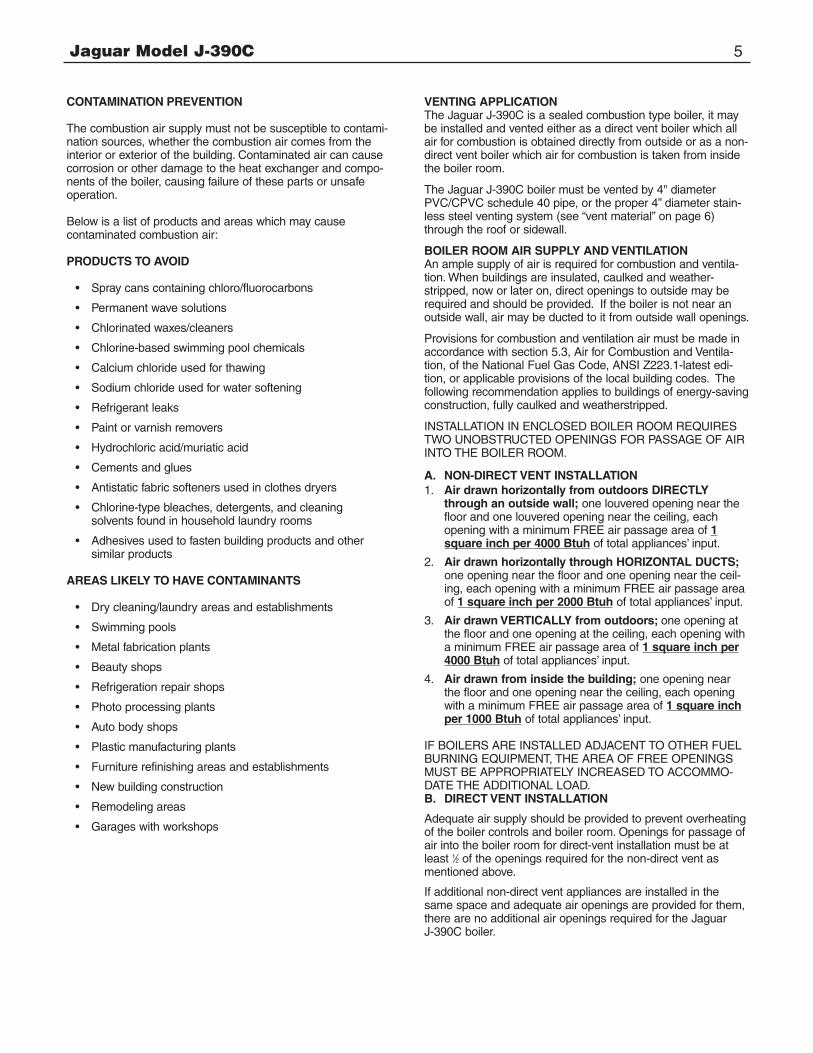
The vent connector on the boiler is designed to directly accom-modate either PVC/CPVC Schedule 40 pipe or the listed stain-less steel vent systems by utilizing an adapter. The adapter hasa built-in sealing ring, so no additional sealant is required.Make sure the pipes are round and burr-free, and push downfully past the sealing ring, until snug. (See Figure 4). Liquidsoap may be used to ease insertion.
The air intake collar on the boiler is designed to directly acco-modate PVC/CPVC schedule 40 pipe (See figure 4). A smallbead of silicon should be applied between the collar and insideof the air antake pipe, to seal properly.
PVC/CPVC PIPE GENERAL ASSEMBLY METHOD
The following are the recommended methods for cutting, cleaning and connecting PVC and CPVC pipe, for both thevent and air intake piping system:
1. When laying out the piping system, work from the boiler vent and air intake adapter to the point of outside termination.
2. Cut the PVC/CPVC pipe to the required lengths, and pre-assemble the entire system, before sealing. Disassembly after sealing, to make any corrections, will notbe possible.
3. Once the pre-assembled PVC/CPVC pipe vent and air intake system is verified to be of the proper length pipe and fitting orientation, begin disassembling and preparing the pipes and fittings for the sealing process. This can be done section by section, or the complete vent and air intake system can be disassembled. It is recommended to mark the various parts, before complete disassembly, to eliminate the possibility of errors during re-assembly.
4. De-burr the inside and outside of every PVC/CPVC pipe, toensure that they engage fully into the fittings, and flow is not compromised. A small chamfer on the outside of each pipe can particularly aid in the final assembly process.
5. Wipe or knock out any debris from inside the PVC or CPVC pipe, which may have accumulated there from the cutting process or storage. Debris can cause operational problems with the boiler combustion components.
6. Thoroughly clean the outside ends of each pipe, and the inside of each fitting. The surfaces must be dry for the sealing agents to work properly. Handle the prepared pipe lengths away from the cleaned ends, and handle the cleaned fittings, from the outside, to avoid contamination.
7. Re-assembly of the PVC or CPVC pipe should be done in sections, to avoid the primer and cement drying before the parts are engaged.
8. For each joint, first apply a coat of primer to the outside sealing surface of the pipe and the inside sealing surface ofeach fitting. Use only the primer type that is specified for either the PVC or CPVC pipe that is bing utilized.
9. Before the primer dries, apply a coat of cement over it. A second coat of cement can be applied, if necessary, but must be done quickly and in a manner that avoids unnecessary build-up that would cause obstruction inside the system. Use only the cement type that is specified for either the PVC or CPVC pipe that is being utilized.
10. Before the cement dries, insert the pipe into the fitting. A slight twisting motion while pushing the pipe into the fitting will aid in distributing the cement evenly and ensuring the parts fully engage.
11. Quickly wipe the excess cement from the outside areas of the joint. Discard any rags used to avoid later getting the cement on hands, clothes and equipment.
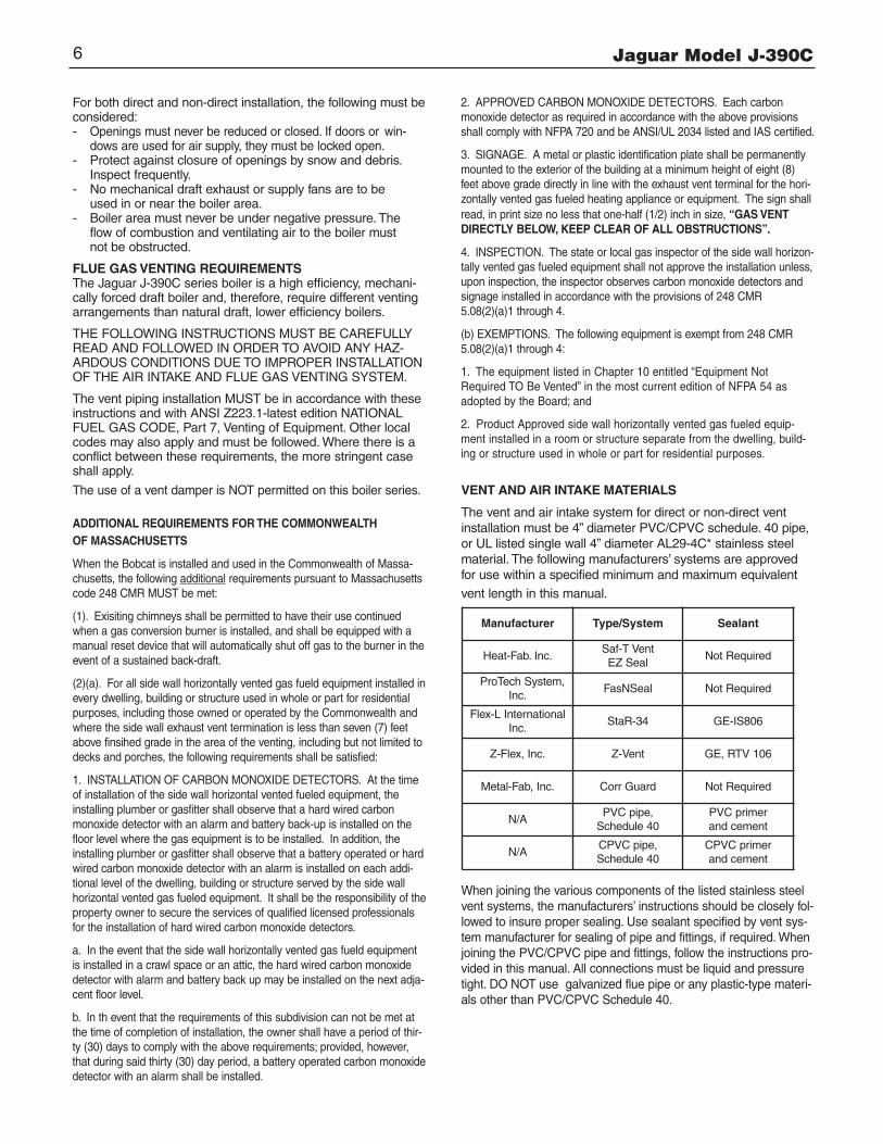
VENT AND AIR INTAKE RESTRICTIONS1. Maximum allowed equivalent vent and air intake length for
all of the approved vent and air intake materials is 100 equivalent feet.
2. Equivalent of vent or air intake length is sum of the straight pipe lengths and equivalent length of elbows.Each 90˚ elbow is equivalent to 10 ft. of 4" pipe.
3. The vent termination is in addition to the allowed equivalent lengths.
4. Minimum vent length is 2 feet of straight pipe, plus one 90˚ elbow.
5. Vent length restriction is for both direct and non-direct vent installations.
EXAMPLE: The combustion air is provided by air intakepiping directly to the boiler (direct-vent installation). The ventpiping will be PVC and installation location will require theuse of 4 elbows for the vent to run the termination. The airintake piping will also be PVC, and also will require the useof 4 elbows.
Figure 5.
4" PVC OR CPVC AIR INTAKE PIPE
AIR INTAKE COLLAR
4" PVC OR CPVCVENT PIPE
Figure 4. Vent & Air Intake Pipe installation into Boiler Adapter.
Jaguar Model J-390C8
In this case, the maximum straight pipe vent length that canbe utilized with the 4 elbows would be: 100’ - (4’ x 10’) = 60’.Since the air intake pipe also is PVC and requires the use of4 elbows, the maximum straight pipe air intake length thatcan be utilized is also 60 feet.
If the air for combustion were taken from the boiler room(non-direct vent installation), still the maximum straight ventlength would be 60 feet.6. The Jaguar J-390C boiler is equipped with a built-in
condensation drain and trap system. The traps must be filled with water. DO NOT operate the boiler without filling the trap with water to prevent flue gas discharge into space. The drain must dispose of possibly large quantities ofcondensate, which may require a neutralizing system. Refer to the “Condensate Drainage” section of this manual. No additional condensation drain and trap is required on the vent piping system itself.
7. The horizontal vent pipe must be sloped upward from the boiler at a pitch of at least 1/4” per 1 foot of run, so that the condensate from the vent system runs to the boiler vent adapter pipe, then out the built-in condensation drain and trap.
8. The horizontal vent and air intake pipes must be supportedwith pipe straps, at intervals no greater than 5 feet, when PVC/CPVC pipe is utilized. This support spacing applies also to stainless steel vent pipe, unless the manufacturer’s instructions permit otherwise. The vertical vent and air intake pipes also must be supported, wherever the building construction provides allowance for it, such as ceiling or roof passage openings where a firestop and support or braces can be affixed.
9. Minimum clearances of vent pipes from combustible constructions must be maintained (see Page 4). No clearance is required between the vent and air intake pipesof this boiler.
10. Common venting with other appliances or another Jaguar boiler is not allowed.
11. DO NOT install a vent damper or similar devices in vent system or on the boiler.
12. DO NOT insulate venting system.
VENTING INSTALLATIONOnly PVC/CPVC and approved stainless steel materials listedon page 6 may be used for the venting system installation. Ifstainless steel vent systems are used, follow the manufactur-er’s instructions, in conjunction with these instructions.
I. Non-Direct Vent InstallationThe air for combustion is taken from the ambient air surrounding the boiler; therefore, ample supply of air is requiredfor combustion and ventilation (see page 6.)
DO NOT use this installation method if the surrounding of theboiler is contaminated. See page 5 for the list of harmful contaminants and their sources, to avoid.
A. SIDEWALL VENTING - NON-DIRECT VENT
Figures 6 and 7 show typical horizontal sidewall venting. Forcombustible wall passage of vent piping, a UL listed thimble or flashing and sealing boot must be used, providing the wallthickness from 3" minimum up to 14" maximum. The vent piping must terminate with a screened tee or elbow terminationfacing down. CAUTION: Flue gasses exiting from the vent terminal will condense. Building materials in the area of the vent terminal
should be protected from discoloration and degradation.
VENT TERMINATION LOCATION AND CLEARANCES1. The venting system shall terminate at least 3 feet above
any forced air inlet located within 10 feet.
2. The venting system shall terminate at least 12 inches below, or 12 inches horizontally from any door, window or gravity air inlet into any building. The bottom of the ventterminal or air intake terminal shall be at least 12 inches above grade or the normal snow level whichever is greater.
3. Through the wall vents shall not terminate over public walkways or over areas where condensate or vapor couldcreate a nuisance or hazard or could be detrimental to the operation of regulators, relief valves or other equip-ment. Minimum clearance of 4 feet horizontal distance is maintained, from electric meters, gas meters, regulators and relief equipment.
4. Vent termination must not be located in any confined space (i.e. window wells, alcoves, narrow alleys) or under any overhang or deck. Vent termination should not allow flue gas discharge towards neighbor’s windows or where personal injury or property damages can occur.
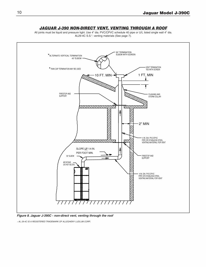
B. NON-DIRECT VENT - VERTICAL VENTINGFigure 8 shows typical venting through the roof. The vent pipemust pass through the ceiling, floor and the roof verticallythrough a 8" minimum diameter cutout. A fire stop is requiredfor each ceiling and floor penetration. For roof passage, anappropriate UL listed roof flashing must be used.
An existing chimney (see Figure 9) may be used as a chase forvertical venting. Other appliances CANNOT be vented into thesame chimney or vent pipe with in the chimney.
The vertical vent piping must terminate with a screened tee,combination of 45˚ elbow and a 90˚ screened elbow termina-tion or a rain cap termination.
II. Direct Vent Installation
Air intake piping from outside to the boiler air intake adapterprovides the air for combustion. The boiler surrounding may becontaminated (See page 5). Piping the air intake to the outsidecan prevent contaminants from the boiler surrounding fromentering the combustion air supply.
A. SIDEWALL DIRECT VENTING
Figures 10 and 11 show typical sidewall direct venting, using aSlant/Fin vent/air intake termination.
CAUTION: Flue gasses existing from the vent terminal will con-dense. Building materials in the area of the terminal should beprotected from discoloration and degradation.
Vent termination location and clearances for non-direct ventstated in paragraph I, also applies to sidewall direct venting.
Alternate sidewall venting for direct or non-direct vent:Vent and/or air intake piping may be installed per figure 11a inorder to provide enough clearance from snow line. The totalvent/air intake equivalent length must not exceed 100 ft.
In cold climates, install an insolated enclosure around the ventpiping to protect from freezing.

Jaguar Model J-390C 9
JAGUAR J-390C NON-DIRECT VENT, SIDEWALL VENTINGAll joints must be liquid and pressure tight. Use 4” dia. PVC/CPVC schedule 40 pipe or U/L listed single wall 4" dia.
AL29-4C S.S.*. venting materials (See page 7).
AIR INTAKE(DO NOT BL0CK)
A U/L LISTED FLASHING AND SEALING BOOT MUST BE USED ON COMBUSTIBLEWALLS.
4 IN. DIA.PVC/CVPCPIPE FORVENT
TERMINATION 90� ELBOW WITH SCREEN
SNOW LINE(SEE DEFINITION)
OUTSIDE WALL
SLOPE UP 1/4 IN.
PER FOOT MIN.FROM BOILER TOVENT TERMINATION
90� ELBOW
6" MIN.10" MAX.
12" MIN
Figure 6. Non-direct vent, side wall venting - utilizing PVC/CPVC pipe for venting.
(DO NOT BL0CK)AIR INTAKE
90� ELBOWSTANDARD
VENT TERMINATIONFROM BOILER TOPER FOOT MIN.
SLOPE UP 1/4 IN.
VENTMATERIAL FORSTEEL VENTINGSTAINLESS4 INCH. DIA.
OUTSIDE VENT TERMINATION ELBOW WITH SCREEN
OUTSIDE WALL
SNOW LINE(SEE DEFINITION)
6" MIN 10" MAX
12" MIN
WALL THIMBLE MUST BE USEDON COMBUSTIBLE WALLS
Figure 7. Non-direct vent, side wall venting - utilizing stainless steel vent materials for venting.
* AL 29-4C IS A REGISTERED TRADEMARK OF ALLEGHENY LUDLUM CORP.
** Definition of Snow Line: Knowledge of local conditions will reveal the maximum height that repeated snowfalls accumulate to. The height should be used as the SNOW LINE.
Jaguar Model J-390C10
JAGUAR J-390 NON-DIRECT VENT, VENTING THROUGH A ROOFAll joints must be liquid and pressure tight. Use 4” dia. PVC/CPVC schedule 40 pipe or U/L listed single wall 4" dia.
AL29-4C S.S.*. venting materials (See page 7).
SUPPORTFIRESTOP AND
RAIN CAP TERMINATION MAY BE USED
*ALTERNATE VERTICAL TERMINATIONELBOW WITH SCREEN90° TERMINATION
*
45° ELBOW
PIPE OR STAINLESS STEEL 4 IN. DIA. PVC/CPVC
FIRESTOP ANDSUPPORT
VENTING MATERIAL FOR VENT
2" M IN
STORM COLLARFLASHING AND
4 IN. DIA. PVC/CPVC
VENTING MATERIAL FOR VENTPIPE OR STAINLESS STEEL
TEE WITH SCREENVENT TERMINATION
SLOPE UP 1/4 IN.
PER FOOT MIN.
(DO NOT BLOCK)AIR INTAKE
90° ELBOW
2" MIN
1 FT. MIN10 FT. MIN
Figure 8. Jaguar J-390C - non-direct vent, venting through the roof
* AL 29-4C IS A REGISTERED TRADEMARK OF ALLEGHENY LUDLUM CORP.

Jaguar Model J-390C 11
JAGUAR J-390C NON - DIRECT VENT, UTILIZING AN EXISTINGCHIMNEY AS A CHASE
All joints must be liquid and pressure tight. Use 4” dia. PVC/CPVC schedule 40 pipe or U/L listed single wall 4" dia.AL29-4C S.S.*. venting materials (See page 7).
CHIMNEYTOP PLATE
VENT TERMINATIONTEE WITH SCREEN
VENTVENTING MATERIAL FORPIPE OR STAINLESS STEEL4 INCH DIA. PVC/CPVC
SEAL CHIMNEY OPENING
VENTVENTING MATERIAL FORPIPE OR STAINLESS STEEL4 INCH DIA. PVC/CPVC
WITH MORTAR OR COVER PLATE
45° ELBOW
RAIN CAP TERMINATION MAY BE USED
ALTERNATE VERTICAL TERMINATION* ELBOW WITH SCREEN90° TERMINATION
PER FOOT MIN.
SLOPE UP 1/4 IN.
90° ELBOW
(DO NOT BLOCK)AIR INTAKE
*
1 FT. MIN
10 FT. MIN
Figure 9. Jaguar J-390C - non-direct vent, utilizing an existing chimney as a chase.
* AL 29-4C IS A REGISTERED TRADEMARK OF ALLEGHENY LUDLUM CORP.

Jaguar Model J-390C12
JAGUAR J-390 - DIRECT VENT, SIDEWALL VENTINGAll joints must be liquid and pressure tight. Use 4” dia. PVC/CPVC schedule 40 pipe or U/L listed single wall 4" dia.
AL29-4C S.S.*. venting materials (See page 7).
SLANT/FINVENT/AIR INTAKE TERMINATION KITPART # 83 0802 000
AIR INTAKELOUVERS
SNOW LINE **(SEE DEFINITION)
OUTSIDE‘WALL
4" DIA PVC/CPVC PIPEFOR AIR INTAKE
3" - 14" THICK WALL
90° ELBOW
4" DIA PVC/CPVCFLUE PIPE
4" DIA PVC/CPVCCOUPLING WITHSCREEN
SLANT/FINVENT/AIR INTAKE TERMINATION KITPART # 83 0802 000TOGETHER WITHSPECIAL KIT FOR STAINLESS STEELVENT PIPE
AIR INTAKELOUVERS
4" DIA STRIGHTSCREENED VENTTERMINATION
SNOW LINE **(SEE DEFINITION)
OUTSIDE WALL
ADAPTOR
4" DIA STAINLESS STEELPIPE FOR VENT
90° ELBOW
4" DIA PVC/CPVCPIPE FOR AIR INTAKE
3" - 14" THICK WALL
Figure 10. Direct vent, sidewall venting illustration;utilizing PVC/CPVC pipe for venting
Figure 11. Direct vent, sidewall venting illustration;utilizing stainless steel vent materials for venting.
* AL 29-4C IS A REGISTERED TRADEMARK OF ALLEGHENY LUDLUM CORP.
** Definition of Snow Line: Knowledge of local conditions will revealthe maximum height that repeated snowfalls accumulate to. The height should be used as the SNOW LINE.
SNOWLINE *
12" MIN.
12" MIN.16" MAX.
S (SNORKEL STYLE)
BIRD SCREEN
BIRD SCREEN
WALL
FLUE PIPEAIR INTAKEPIPE20
20" MAX.
D
11a (for JAGUAR J-40 Rev.A)
Figure 11a. Sidewall venting and air intake piping(snorkel style)
Jaguar Model J-390C 13
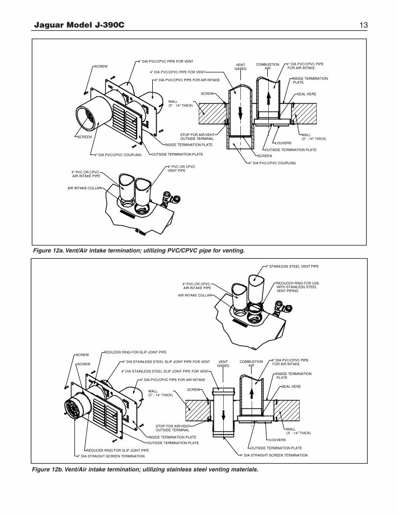
Figure 12a. Vent/Air intake termination; utilizing PVC/CPVC pipe for venting.
Figure 12b. Vent/Air intake termination; utilizing stainless steel venting materials.
4" DIA PVC/CPVC PIPE FOR VENT
4" DIA PVC/CPVC PIPE FOR AIR INTAKE
4
INSIDE TERMINATION PLATE
OUTSIDE TERMINATION PLATE
SCREEN
4" DIA PVC/CPVC COUPLING
SCREW
WALL(3" - 14" THICK)
COMBUSTIONAIR
VENTGASES
STOP FOR AIR/VENTOUTSIDE TERMINAL
4" DIA PVC/CPVC COUPLING
SCREEN
LOUVERS
SEAL HERE
OUTSIDE TERMINATION PLATE
INSIDE TERMINATION PLATE
4" DIA PVC/CPVC PIPE FOR AIR INTAKE
4" DIA PVC/CPVC PIPE FOR VENT
WALL(3" - 14" THICK)
SCREW
S
4" PVC OR CPVC AIR INTAKE PIPE
4" PVC OR CPVCVENT PIPE
AIR INTAKE COLLAR
4" DIA PVC/CPVC PIPE FOR AIR INTAKE
4" DIA STAINLESS STEEL SLIP JOINT PIPE FOR VENT
I
SCREW
INSIDE TERMINATION PLATE
4" DIA STRAIGHT SCREEN TERMINATION
OUTSIDE TERMINATION PLATE
REDUCER RING FOR SLIP JOINT PIPE
REDUCER RING FOR SLIP JOINT PIPE
4" DIA STAINLESS STEEL SLIP JOINT PIPE FOR VENT
VENTGASES
COMBUSTIONAIR
4" DIA PVC/CPVC PIPE FOR AIR INTAKE
INSIDE TERMINATION PLATE
SEAL HERE
WALL(3" - 14" THICK)
OUTSIDE TERMINATION PLATE
LOUVERS
STOP FOR AIR/VENTOUTSIDE TERMINAL
SCREWWALL(3" - 14" THICK)
4" DIA STRAIGHT SCREEN TERMINATION
SCREW
AIR INTAKE COLLAR
REDUCER RING FOR USE WITH STAINLESS STEEL VENT PIPING
4" STAINLESS STEEL VENT PIPE
4" PVC OR CPVC AIR INTAKE PIPE
4
Jaguar Model J-390C14
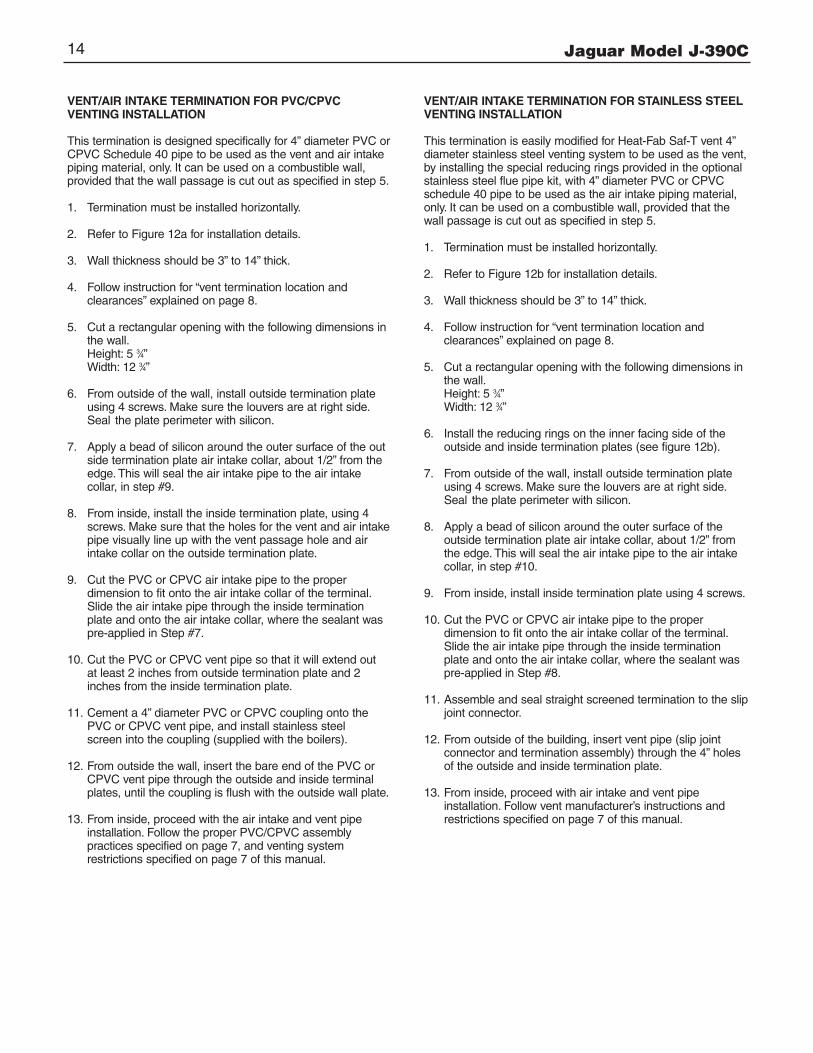
VENT/AIR INTAKE TERMINATION FOR PVC/CPVC VENTING INSTALLATION
This termination is designed specifically for 4” diameter PVC orCPVC Schedule 40 pipe to be used as the vent and air intakepiping material, only. It can be used on a combustible wall, provided that the wall passage is cut out as specified in step 5.
1. Termination must be installed horizontally.
2. Refer to Figure 12a for installation details.
3. Wall thickness should be 3” to 14” thick.
4. Follow instruction for “vent termination location and clearances” explained on page 8.
5. Cut a rectangular opening with the following dimensions in the wall.Height: 5 3⁄4”Width: 12 3⁄4”
6. From outside of the wall, install outside termination plate using 4 screws. Make sure the louvers are at right side. Seal the plate perimeter with silicon.
7. Apply a bead of silicon around the outer surface of the outside termination plate air intake collar, about 1/2” from the edge. This will seal the air intake pipe to the air intake collar, in step #9.
8. From inside, install the inside termination plate, using 4 screws. Make sure that the holes for the vent and air intakepipe visually line up with the vent passage hole and air intake collar on the outside termination plate.
9. Cut the PVC or CPVC air intake pipe to the proper dimension to fit onto the air intake collar of the terminal. Slide the air intake pipe through the inside termination plate and onto the air intake collar, where the sealant was pre-applied in Step #7.
10. Cut the PVC or CPVC vent pipe so that it will extend out at least 2 inches from outside termination plate and 2inches from the inside termination plate.
11. Cement a 4” diameter PVC or CPVC coupling onto the PVC or CPVC vent pipe, and install stainless steel screen into the coupling (supplied with the boilers).
12. From outside the wall, insert the bare end of the PVC or CPVC vent pipe through the outside and inside terminal plates, until the coupling is flush with the outside wall plate.
13. From inside, proceed with the air intake and vent pipe installation. Follow the proper PVC/CPVC assembly practices specified on page 7, and venting system restrictions specified on page 7 of this manual.
VENT/AIR INTAKE TERMINATION FOR STAINLESS STEELVENTING INSTALLATION
This termination is easily modified for Heat-Fab Saf-T vent 4”diameter stainless steel venting system to be used as the vent,by installing the special reducing rings provided in the optionalstainless steel flue pipe kit, with 4” diameter PVC or CPVCschedule 40 pipe to be used as the air intake piping material,only. It can be used on a combustible wall, provided that thewall passage is cut out as specified in step 5.
1. Termination must be installed horizontally.
2. Refer to Figure 12b for installation details.
3. Wall thickness should be 3” to 14” thick.
4. Follow instruction for “vent termination location and clearances” explained on page 8.
5. Cut a rectangular opening with the following dimensions in the wall.Height: 5 3⁄4”Width: 12 3⁄4”
6. Install the reducing rings on the inner facing side of the outside and inside termination plates (see figure 12b).
7. From outside of the wall, install outside termination plate using 4 screws. Make sure the louvers are at right side. Seal the plate perimeter with silicon.
8. Apply a bead of silicon around the outer surface of the outside termination plate air intake collar, about 1/2” from the edge. This will seal the air intake pipe to the air intake collar, in step #10.
9. From inside, install inside termination plate using 4 screws.
10. Cut the PVC or CPVC air intake pipe to the proper dimension to fit onto the air intake collar of the terminal. Slide the air intake pipe through the inside termination plate and onto the air intake collar, where the sealant was pre-applied in Step #8.
11. Assemble and seal straight screened termination to the slipjoint connector.
12. From outside of the building, insert vent pipe (slip joint connector and termination assembly) through the 4” holes of the outside and inside termination plate.
13. From inside, proceed with air intake and vent pipe installation. Follow vent manufacturer’s instructions and restrictions specified on page 7 of this manual.

Jaguar Model J-390C 15
B. DIRECT VENT - VENTING AND AIR INTAKE THROUGH A ROOF
Figure 13 shows typical vertical venting. The vent pipe must pass through the ceiling, floor and the roof vertically through a8” minimum diameter cutout. A fire stop is required for eachceiling and floor penetration. For roof passage an appropriateUL listed roof flashing must be used.
The vertical vent piping must terminate with a screened straight termination. The air intake termination should be ascreened 180˚ elbow facing down. The air intake opening mustbe at least 1 foot below the vent opening.
For PVC/CPVC pipe, follow the proper assembly practicesspecified on page 7, and venting system restrictions specifiedon page 7 of this manual. For stainless steel venting systems,follow the vent manufacturer’s instructions and the restrictionsspecified on page 7 of this manual
Alternate air intake for venting through a roof (see fig. 13) orutilizing an existing chimney as a chae (see fig. 9): Air intakemay be piped to the boiler from the sidewall as shown onfig. 13a.
JAGUAR J-390C - DIRECT VENT, VENTING AND AIR INTAKE THROUGH A ROOF
All joints must be liquid and pressure tight. Use 4” dia. PVC/CPVC schedule 40 pipe or U/L listed single wall 4" dia.AL29-4C S.S.*. venting materials (See page 7).
SNOW LINESUPPORT
FIRESTOP AND
PER FOOT MIN.SLOPE UP 1/4 IN.
PIPE
WITH SCREENSTORM COLLAR
STRAIGHT TERMINATIONFLASHING AND
180° ELBOWWITH SCREEN
AIR INTAKE
AIR INTAKE
4" DIA. PVC/CPVC
PIPE FOR
SUPPORT
SUPPORTFIRESTOP AND
4" DIA PVC/CPVCOR STAINLESSSTEEL MATERIALFOR VENT
2" MIN.
10 FT. MIN.
1 FT. MIN.
1 FT. MIN
Figure 13. Direct vent, venting and air intake through a roof. Figure 13a. Direct vent, venting through a roof and air intake sidewalls.
* AL 29-4C IS A REGISTERED TRADEMARK OF ALLEGHENY LUDLUM CORP.
** Definition of Snow Line: Knowledge of local conditions will reveal the maximum height that repeated snowfalls accumulate to. The height should be used as the SNOW LINE.

Jaguar Model J-390C16
VENTING AND AIR INTAKE SYSTEM REGULAR INSPECTION
A. Inspect the system regularly for condensation, corrosion, sagging and/or physical damage. A qualified professional should service the boiler annually and include such an inspection at that time. The homeowner should look over the system monthly for damage, water stains, any signs of rust, other corrosions or separation of the vent and air intake piping(if direct-vent).
B. Should an inspection turn up signs of condensation, corrosion, sagging or damage, the boiler should be shut downimmediately and the condition should be corrected by a qualified professional.
CONDENSATE REMOVAL SYSTEMThe Jaguar J-390C boiler is equipped with a built-in condensationdrain and trap system. This system consists of two traps, onebeing dedicated to the condensate produced by the boiler, andanother being dedicated to the condensate produced within thevent piping. (See page 13 for the location of each of the traps).Both of these traps must be filled with water. This is most easilyaccomplished by pouring water from a small container into thevent connector at the top of the boiler, before the vent pipe isattached, until the tubing loop trap in the rear of the boiler is visi-bly filled. DO NOT operate the boiler without filling the trap withwater to prevent flue gas discharge into space. Periodic inspectionshould be made of this assembly for deterioration of the tubingand components, and to insure that the traps are not plugged. Ifany part is plugged or appears to have excessive sediment within,it should be removed from the drain assembly, have the obstruc-tion cleared, refilled with water and reinstalled as before.
A 3/4” PVC tee assembly, located in the rear of the boiler jacket,is provided to run the condensate liquid from the boiler. Connectthe plastic tubing that will be run to the drain to the bottom take-off of the tee. Leave the top take-off of the tee open, to act as avacuum breaker. If the building drain is above the bottom portionof the tee, a condensate removal pump will be required. Thispump must have an overflow switch, and be compatible with theacidic condensate liquid, as must all fittings and the tubing usedin this condensate removal system. (See Figure 14).
No part of the condensate removal system can be exposed tofreezing temperatures, or any other conditions that could causeblockage. DO NOT run drain tubing to the outside of the building.In addition, certain jurisdictions or drain pipe materials mayrequire a neutralization unit to be installed in the condensateremoval system. Any piping other than plastic types will be subject to corrosion or deterioration from the acidic conden
sate, which may have a pH level as low as 3.0. A condensatefilter containing lime, marble, or phosphate chips can neutralizethe condensate to a pH level above 6.5, which is safe for alldrain piping materials. (See Figure 14). The neutralizing filtermedium will require periodic changing, to ensure it’s affective-ness. Replacing the medium on an annual basis is recom-mended, or refer to the manufacturer’s instructions for systemsthat are available for neutralizing condensate.
COMMONWEALTH OF MASSACHUSETTS SPECIALREQUIREMENT
When the Jaguar J-390C is installed and used in the Common-wealth of Massachusetts, a neutralization unit MUST be installedin the condensate removal system.
GAS PIPINGA. Local installation codes apply. The pipe joint compound
used on threads must be resistant to the action of liquefiedpetroleum gases.
B. The gas supply line to the boiler should run directly from the meterA manual gas supply shut-off valve is provided on the boiler’s gassupply pipe. (See Figure 2, on page 3). Local codes may specify amanual main gas supply shut-off valve to be 5’ above the floor, anda disconnection union at the gas piping entrance to the boiler. Inthis case, the gas supply shut-off valve must be relocated to thespecified location. If the gas supply pipe must be upsized for flowconsiderations, then the same size main gas supply shut-off valvemust be used.
Selecting pipe size for natural gas:1. Measure or estimate the length of piping from the meter
to the installation site.2. Consult gas supplier for heating value of gas (Btu/cu. ft.).3. Divide boiler rated input by heating value to find gas flow
in piping (cu. ft. per hour).4. Use table below to select proper pipe size.
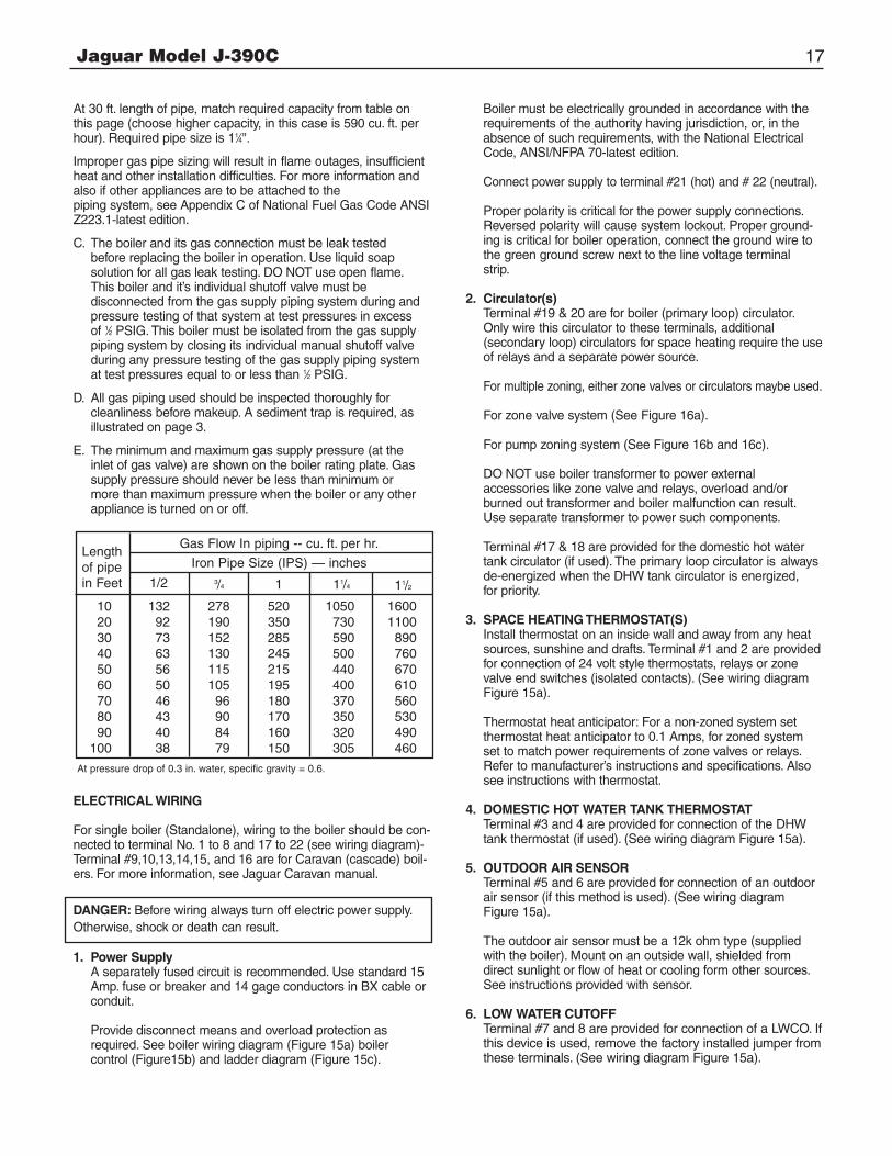
EXAMPLE: Distance from gas meter to the boiler is 30ft.Heating value of natural gas is 1020 Btu/cu. Ft. Select properpipe size.
Gas flow = 390,000 Btu/hr = 382 cu. ft. per hour1020 Btu/cu. ft.
NEUTRALIZING UNIT (IF REQUIRED)
CONDENSATE PUMP (IF REQUIRED)
DRAIN INSIDE BUILDING
PLASTIC TUBING
DRAIN VACUUM BREAKER, LEAVE OPEN
Figure 14. Condensate disposal system
Jaguar Model J-390C 17
At 30 ft. length of pipe, match required capacity from table onthis page (choose higher capacity, in this case is 590 cu. ft. perhour). Required pipe size is 11⁄4".
Improper gas pipe sizing will result in flame outages, insufficientheat and other installation difficulties. For more information andalso if other appliances are to be attached to the piping system, see Appendix C of National Fuel Gas Code ANSIZ223.1-latest edition.
C. The boiler and its gas connection must be leak tested before replacing the boiler in operation. Use liquid soap solution for all gas leak testing. DO NOT use open flame. This boiler and it’s individual shutoff valve must be disconnected from the gas supply piping system during and pressure testing of that system at test pressures in excess of 1⁄2 PSIG. This boiler must be isolated from the gas supply piping system by closing its individual manual shutoff valve during any pressure testing of the gas supply piping system at test pressures equal to or less than 1⁄2 PSIG.
D. All gas piping used should be inspected thoroughly for cleanliness before makeup. A sediment trap is required, as illustrated on page 3.
E. The minimum and maximum gas supply pressure (at the inlet of gas valve) are shown on the boiler rating plate. Gas supply pressure should never be less than minimum or more than maximum pressure when the boiler or any other appliance is turned on or off.
ELECTRICAL WIRING
For single boiler (Standalone), wiring to the boiler should be con-nected to terminal No. 1 to 8 and 17 to 22 (see wiring diagram)-Terminal #9,10,13,14,15, and 16 are for Caravan (cascade) boil-ers. For more information, see Jaguar Caravan manual.
DANGER: Before wiring always turn off electric power supply.Otherwise, shock or death can result.
1. Power SupplyA separately fused circuit is recommended. Use standard 15Amp. fuse or breaker and 14 gage conductors in BX cable orconduit.
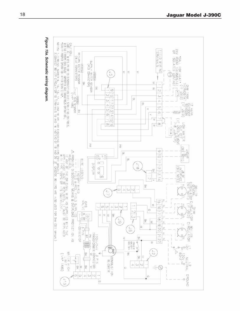
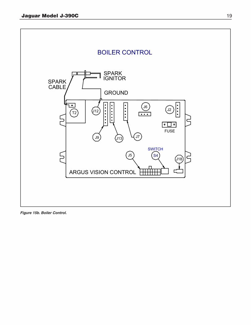
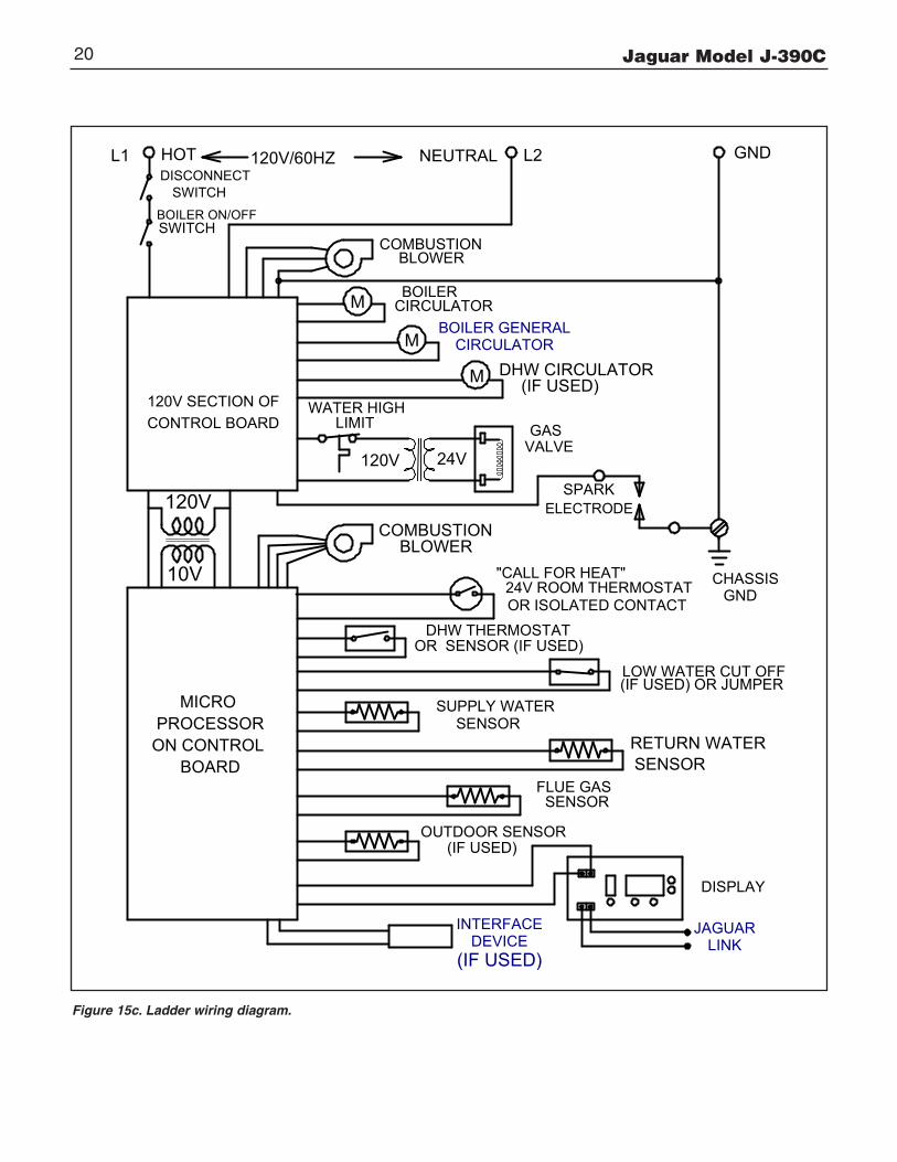
Provide disconnect means and overload protection as required. See boiler wiring diagram (Figure 15a) boiler control (Figure15b) and ladder diagram (Figure 15c).
Boiler must be electrically grounded in accordance with the requirements of the authority having jurisdiction, or, in the absence of such requirements, with the National Electrical Code, ANSI/NFPA 70-latest edition.
Connect power supply to terminal #21 (hot) and # 22 (neutral).
Proper polarity is critical for the power supply connections. Reversed polarity will cause system lockout. Proper ground-ing is critical for boiler operation, connect the ground wire to the green ground screw next to the line voltage terminal strip.
2. Circulator(s)Terminal #19 & 20 are for boiler (primary loop) circulator. Only wire this circulator to these terminals, additional(secondary loop) circulators for space heating require the use of relays and a separate power source.
For multiple zoning, either zone valves or circulators maybe used.
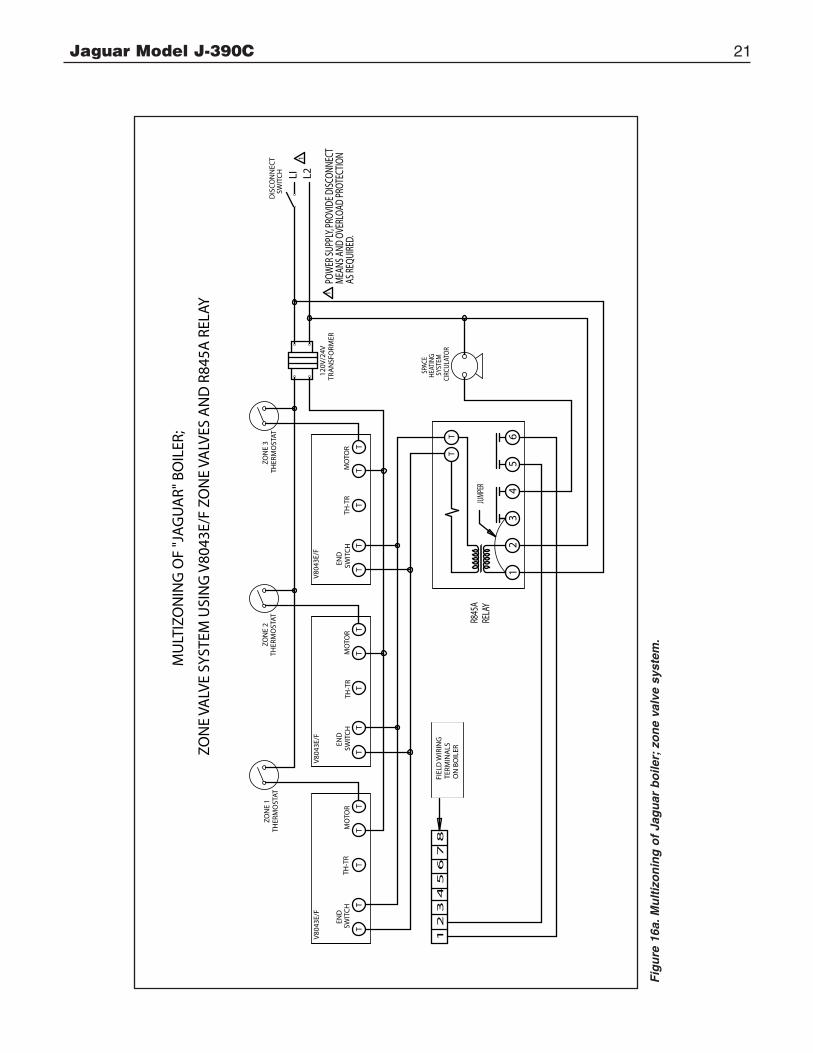
For zone valve system (See Figure 16a).
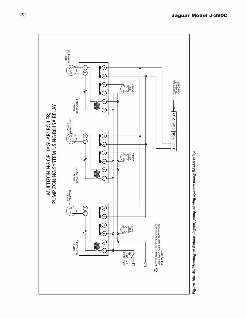
For pump zoning system (See Figure 16b and 16c).
DO NOT use boiler transformer to power external accessories like zone valve and relays, overload and/or burned out transformer and boiler malfunction can result. Use separate transformer to power such components.
Terminal #17 & 18 are provided for the domestic hot water tank circulator (if used). The primary loop circulator is always de-energized when the DHW tank circulator is energized,for priority.
3. SPACE HEATING THERMOSTAT(S)Install thermostat on an inside wall and away from any heatsources, sunshine and drafts. Terminal #1 and 2 are providedfor connection of 24 volt style thermostats, relays or zonevalve end switches (isolated contacts). (See wiring diagramFigure 15a).
Thermostat heat anticipator: For a non-zoned system set thermostat heat anticipator to 0.1 Amps, for zoned system set to match power requirements of zone valves or relays. Refer to manufacturer’s instructions and specifications. Also see instructions with thermostat.
4. DOMESTIC HOT WATER TANK THERMOSTATTerminal #3 and 4 are provided for connection of the DHW tank thermostat (if used). (See wiring diagram Figure 15a).
5. OUTDOOR AIR SENSORTerminal #5 and 6 are provided for connection of an outdoor air sensor (if this method is used). (See wiring diagram Figure 15a).
The outdoor air sensor must be a 12k ohm type (supplied with the boiler). Mount on an outside wall, shielded from direct sunlight or flow of heat or cooling form other sources. See instructions provided with sensor.
6. LOW WATER CUTOFFTerminal #7 and 8 are provided for connection of a LWCO. Ifthis device is used, remove the factory installed jumper fromthese terminals. (See wiring diagram Figure 15a).
Lengthof pipein Feet 1/2 3/4 1 11/4 11/2
Gas Flow In piping -- cu. ft. per hr.
Iron Pipe Size (IPS) — inches
10 132 278 520 1050 160020 92 190 350 730 110030 73 152 285 590 89040 63 130 245 500 76050 56 115 215 440 67060 50 105 195 400 61070 46 96 180 370 56080 43 90 170 350 53090 40 84 160 320 490100 38 79 150 305 460
At pressure drop of 0.3 in. water, specific gravity = 0.6.
Jaguar Model J-390C18
Fig
ure 15a. S
chem
atic wirin
g d
iagram
.
Jaguar Model J-390C 19
ARGUS VISION CONTROL
J7
J18
T2 J12
J13
SPARK IGNITORSPARK
CABLEGROUND
FUSEJ9
J6J2
J5 S4
SWITCH
F
BOILER CONTROL
Figure 15b. Boiler Control.
Jaguar Model J-390C20
GNDNEUTRALHOT L2L1 120V/60HZ
120V
10V
120V 24V
DISPLAY
WATER HIGH LIMIT
"CALL FOR HEAT"24V ROOM THERMOSTAT
DHW THERMOSTAT OR SENSOR (IF USED)
LOW WATER CUT OFF(IF USED) OR JUMPER
120V SECTION OFCONTROL BOARD
MICRO PROCESSOR
ON CONTROL BOARD
OUTDOOR SENSOR(IF USED)
FLUE GAS SENSOR
RETURN WATER SENSOR
SUPPLY WATER SENSOR
GAS VALVE
BOILER ON/OFFSWITCH
COMBUSTIONBLOWER
BOILERCIRCULATOR
DHW CIRCULATOR(IF USED)
SPARKELECTRODE
DISCONNECTSWITCH
CHASSIS GNDOR ISOLATED CONTACT
COMBUSTIONBLOWER
M
M
MBOILER GENERAL
CIRCULATOR
INTERFACEDEVICE
(IF USED)
JAGUARLINK
F
Figure 15c. Ladder wiring diagram.
Jaguar Model J-390C 21
1
END
SWIT
CH
TH-T
RM
OTO
R
2
T
TT
TT
TT
TT
TT
TT
TT
T
T
34
56
SPAC
EH
EATI
NG
SYST
EMCI
RCU
LATO
R
END
SWIT
CH
TH-T
RM
OTO
R
ZON
E 2
THER
MO
STAT
V80
43E/
F
END
SWIT
CH
TH-T
RM
OTO
R
ZON
E 3
THER
MO
STAT
V80
43E/
F
1 2
3 4
5 6
7 8
FIEL
D W
IRIN
GTE
RMIN
ALS
ON
BO
ILER
JUMP
ERR8
45A
RELA
Y
LI L21
ZON
E 1
THER
MO
STAT
120V
/24V
TRA
NSF
ORM
ER1
POW
ER SU
PPLY
, PRO
VIDE
DIS
CONN
ECT
MEA
NS A
ND O
VERL
OAD
PROT
ECTI
ON A
S REQ
UIRE
D.
MU
LTIZ
ON
ING
OF
"JA
GU
AR"
BO
ILER
;
ZO
NE
VALV
E SY
STEM
USI
NG
V80
43E/
F ZO
NE
VALV
ES A
ND
R84
5A R
ELAY
DIS
CO
NN
ECT
SWIT
CH
V80
43E/
F
Fig
ure
16a
. Mu
ltiz
on
ing
of
Jag
uar
bo
iler;
zo
ne
valv
e sy
stem
.
Jaguar Model J-390C22
Fig
ure
16b
. Mu
ltiz
on
ing
of
Bo
bca
t Ja
gu
ar;
pu
mp
zo
nin
g s
yste
m u
sin
g R
845A
rel
ay.1
2 3
4 5
6 7
8FI
ELD
WIR
ING
TERM
INA
LSO
N B
OIL
ER
12
TT
34
56
TT
TT
LI L2DIS
CO
NN
ECT
SWIT
CH
1
R845
ARE
LAY
ZO
NE
3
CIR
C.
ZON
E 3
R845
ARE
LAY
ZO
NE
2
CIR
C.
ZON
E 2
R845
ARE
LAY
ZO
NE
1
CIR
C.
ZON
E 1
ZON
E 3
THER
MO
STAT
ZON
E 2
THER
MO
STAT
ZON
E 1
THER
MO
STAT
1PO
WER
SU
PPLY
, PR
OV
IDE
DIS
CO
NN
ECT
MEA
NS
AN
D O
VER
LOA
D P
RO
TEC
TIO
N A
S RE
QU
IRED
.
MU
LTIZ
ON
ING
OF
"JA
GU
AR"
BO
ILER
;PU
MP
ZON
ING
SYS
TEM
USI
NG
R84
5A R
ELAY
12
34
56
12
34
56
Jaguar Model J-390C 23
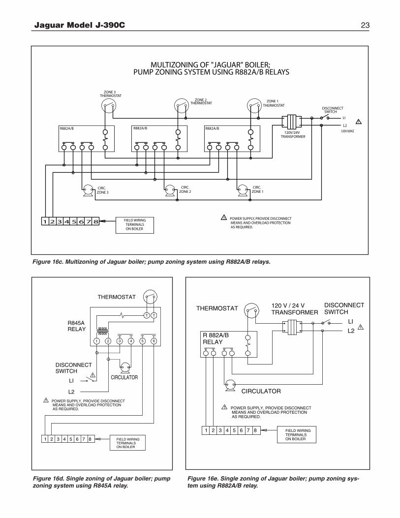
Figure 16c. Multizoning of Jaguar boiler; pump zoning system using R882A/B relays.
LI
L21
DISCONNECTSWITCH
120V/24VTRANSFORMER
FIELD WIRINGTERMINALSON BOILER
CIRC.ZONE 3
ZONE 3THERMOSTAT
1 POWER SUPPLY, PROVIDE DISCONNECT MEANS AND OVERLOAD PROTECTION AS REQUIRED.
MULTIZONING OF "JAGUAR" BOILER;PUMP ZONING SYSTEM USING R882A/B RELAYS
CIRC.ZONE 2
R882A/BR882A/B
ZONE 2THERMOSTAT
CIRC.ZONE 1
R882A/B
ZONE 1THERMOSTAT
120V/60HZ
1 2 3 4 5 6 7 8
1 2 3 4 5 6 7 8
1 2
T T
3 4 5 6
LI
L2
1
1 POWER SUPPLY, PROVIDE DISCONNECT MEANS AND OVERLOAD PROTECTION AS REQUIRED.
DISCONNECTSWITCH
R845ARELAY
THERMOSTAT
CIRCULATOR
FIELD WIRINGTERMINALSON BOILER
Figure 16d. Single zoning of Jaguar boiler; pumpzoning system using R845A relay.
Figure 16e. Single zoning of Jaguar boiler; pump zoning sys-tem using R882A/B relay.
LI
L21
1
1 2 3 4 5 6 7 8
POWER SUPPLY, PROVIDE DISCONNECT MEANS AND OVERLOAD PROTECTION AS REQUIRED.
DISCONNECTSWITCH
THERMOSTAT
CIRCULATOR
R 882A/BRELAY
120 V / 24 VTRANSFORMER
FIELD WIRINGTERMINALSON BOILER

Jaguar Model J-390C24
WATER PIPING
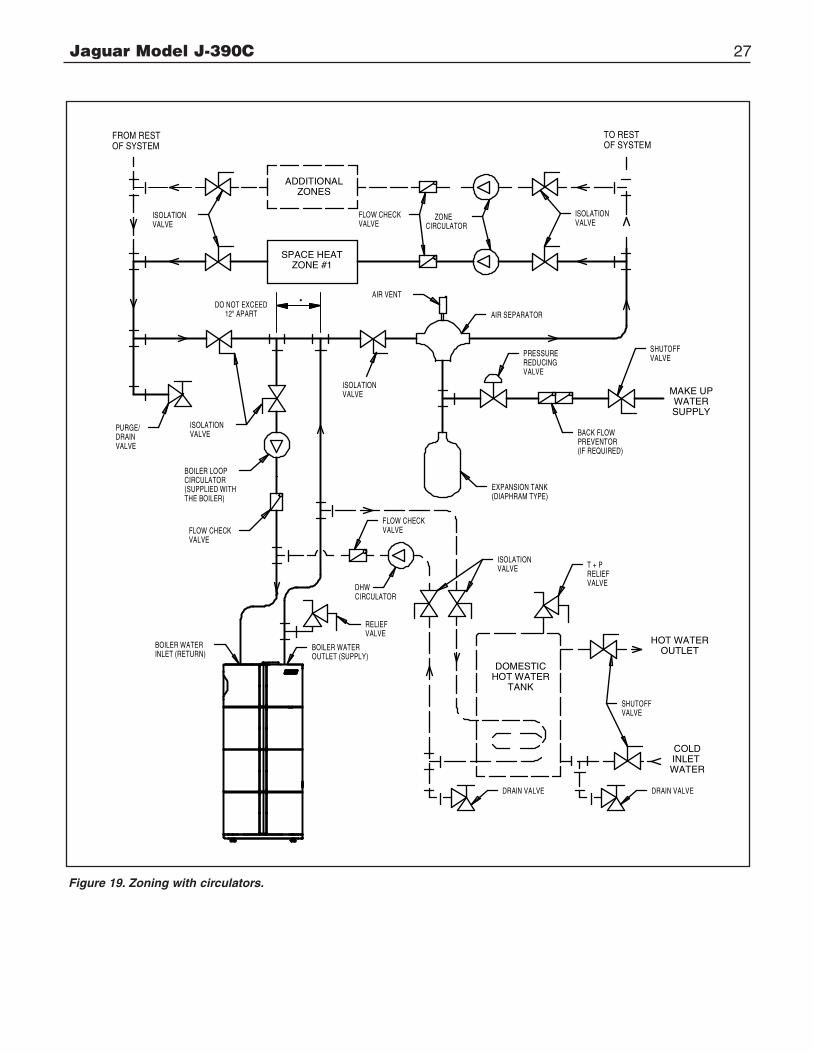
A. Connection of system to boiler:Primary/secondary piping of the system is recommended, to ensure the proper flow through the boiler. (See Figures 19 through 21). The boiler loop piping must be the same diameter as the water outlet (supply) and inlet (return) piping connections provided on the boiler, particularly on longer loops. See page 2 for piping connection size.
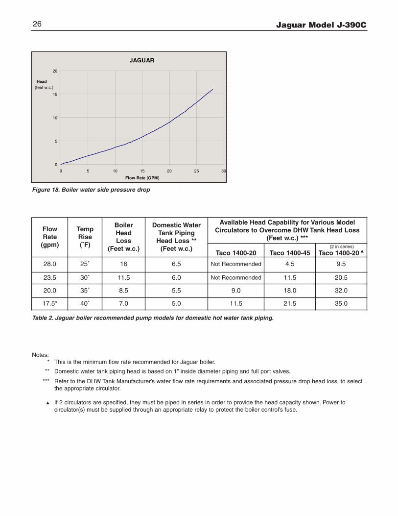
B. Circulator Pumps:The boiler loop piping must utilize the Taco 1400-20 circulator that is supplied with the boiler, to ensure the proper flow through the boiler. Refer to Figure 18 for the boiler water side pressure drop and Table 2 for the recommended pumpmodels for the domestic hot water system. Install the pumps in the orientation shown in Figures 19 through 21.
C. Relief Valve(supplied with boiler):Tee the relief valve into the boiler water outlet (supply) piping as close to the water outlet (supply) connection as possible. (See Figure 17). The relief valve’s discharge piping must be the same size or larger than the relief valve’s outlet, and must terminate 6” minimum from floor with a plain (no threads) end.Place a bucket under pressure relief valve discharge. Make sure discharge is always visible. DO NOT hard-pipe to drain piping, or any place where freezing could occur. No shut-off valve is permitted between the relief valve and boiler, or in thedischarge line.
D. Air Control System:An appropriately sized diaphragm-type expansion tank must be used to control the system pressure. See boiler volume data on page 2, and the recommended location in Figures 19 through 21. An air vent is recommended to be installed on an air separator in close proximity to the expansion tank.
E. Cold Water Fill:A pressure reducing (fill) valve, with a shut-off valve upstreamof it, should be installed in close proximity of the expansion tank. (See Figures 19 through 21). Use a back flow check valve in the cold water supply as required by local codes.
F. Low Water Cutoff:On a hot water boiler installed above radiation level, the boilermust be provided with a low water cutoff device at the time of installation by the installer (see Figure 17 for piping arrangement).
G. Water Treatment and Freeze Protection:A good water treatment program will not only extend the useful life of this boiler but it will also save much of the time and expense of repairs made necessary by preventable occurrences. A reputable water treatment company that has experience with aluminum boilers should be consulted toevaluate and determine the best overall treatment program for your boiler.
The heat exchanger of this boiler is made of aluminum, so the system water PH must be maintained between 7.5 and 8.5 level.
Procedure:1. Thoroughly drain and flush the system (new or used)
with fresh water before connecting the boiler to the system to remove any sediment or glycol.
2. Install the boiler per instructions in this manual.3. It is recommended to clean the heating system with
proper cleaner. Do not use phosphate-based (TSP) cleaners, as they will harm aluminum heat exchanger. Follow manufacturer instruction. Rhomar Hydro-Solv 9100 is recommended (add approximately 1 gallon per 50 gallon of system water). Circulate cleaner for minimum of 1/2 hour, and then thoroughly flush until the water runs clear.
4. It is recommended to add system treatment (inhibitor). Do not use phosphate, nitrate or high pH products. Follow manufacturer instructions. Rhomar Pro-Tek 922 is recommended at the rate of 1 gallon per 50 gallon of system water.Note: Extra inhibitor may not be needed if using the approved antifreeze containing inhibitor additive as listed below.Test the PH of the water system annually, if the PH is out of the range (7.5-8.5), the inhibitor level may not be sufficient, add inhibitor to the system.
5. Anti-freeze is sometimes used in hydronic systems to protect against freeze-up in the event of power failure or boiler shut down in the cold winter.
Approved anti-freeze is RhoGard (propylene glycol with Pro-Tek 922 inhibitor) by Rhomar WaterManagement Inc. or Noburst AL by Noble. Follow the manufacturer’s instructions for proper application and proper mixture for the minimum ambient temperature. Any use of anti-freeze other than that supplied by Slant/Fin or approved will void the warranty.
Keep water hardness less than 7 grains/gallon. It is recommended to use water softener for hard water areas or if well water is used.
Never use Ethylene glycol, as it is toxic to humans.Never use any type of automotive or standard glycol freeze protection fluid. Do not exceed 50% by volume concentrate of anti-freeze. Check anti-freezeconcentration annually.
H. Piping a heating - cooling system to a water boiler and chiller:Figure 21 illustrates a method of piping a heating-cooling system to a water boiler and a chiller. Hand valves (shown)or automatic valves must be installed to prevent circulationof chilled water in the boiler or hot water in the chiller.
The air control system and pressure control system must operate with chiller only, or the boiler only, being valved to the piping system. Separate control devices on the boiler and chiller may be used, or a single set of air and pres-sure controls on the common piping may be preferred.
If the boiler is used to supply hot water to heating coils in air handling units, flow control valves or other devices must be installed to prevent gravity circulation of water in the coils during the cooling cycle.

Jaguar Model J-390C 25
WATER OUTLET PIPINGTO REST OF THE SYSTEM
PROBE TYPE LOW WATER CUTOFF(IF REQUIRED)
PRESSURE RELIEF VALVE(SUPPLIED WITH BOILER)
1 1/4" x 1 1/4" x 3/4" NPT TEE
3/4" NPT STREET ELBOW
1 1/4" NPT STREET ELBOW
WATER OUTLET (SUPPLY)PIPE 1 1/4" DIAMETER
WATER INLET (RETURN) PIPE 1 1/4" DIAMETER
RELIEF VALVEDISCHARGE PIPING
1 1/4" NPT TEE
INSTALL MANUAL MAINSHUTOFF VALVE 5'ABOVE FLOOR, WHENREQUIRED BY LOCAL CODE
GAS SUPPLY VALVE
SEDIMENT TRAP
1 1/4" X 1/4" NPT REDUCER BUSHING
PRESSURE & TEMPERATURE GAUGE * (SUPPLIED WITH BOILER)
LOW WATER CUTOFF MANIFOLD (IF LWCO UTILIZED)
* Gauge must face front of boiler, in clear view
Figure 17. Relief valve, pressure/temperature gauge and low water cutoff installation.
Jaguar Model J-390C26
Table 2. Jaguar boiler recommended pump models for domestic hot water tank piping.
FlowRate(gpm)
TempRise(˚F)
BoilerHeadLoss
(Feet w.c.)
Domestic WaterTank PipingHead Loss **(Feet w.c.)
Available Head Capability for Various ModelCirculators to Overcome DHW Tank Head Loss
(Feet w.c.) ***
Taco 1400-20 Taco 1400-45 Taco 1400-20 ▲
28.0 25˚ 16 6.5 Not Recommended 4.5 9.5
23.5 30˚ 11.5 6.0 Not Recommended 11.5 20.5
20.0 35˚ 8.5 5.5 9.0 18.0 32.0
17.5* 40˚ 7.0 5.0 11.5 21.5 35.0
Figure 18. Boiler water side pressure drop
PRESSURE DROP
FLOW RATE Boiler heat losORIGINAL
gpm Feet w.c DATA
28 16 14.53
23.4 11.77 11.77
20.04 9 8.77
17.55 7.38 7.38
14.04 5.3 5.3
11.7 4.2 3.46
0 0 0
column modified
8/25/2007
JAGUAR
0
5
10
15
20
0 5 10 15 20 25 30
Flow Rate (GPM)
Head
(feet w.c.)
Notes:* This is the minimum flow rate recommended for Jaguar boiler.
** Domestic water tank piping head is based on 1” inside diameter piping and full port valves.
*** Refer to the DHW Tank Manufacturer’s water flow rate requirements and associated pressure drop head loss, to select the appropriate circulator.
▲ If 2 circulators are specified, they must be piped in series in order to provide the head capacity shown. Power tocirculator(s) must be supplied through an appropriate relay to protect the boiler control’s fuse.
(2 in series)
Jaguar Model J-390C 27
ISOLATIONVALVE
BOILER LOOP
PURGE/
VALVEDRAIN
THE BOILER)
CIRCULATOR(SUPPLIED WITH
ISOLATIONVALVE
FLOW CHECKVALVE
ISOLATIONVALVE
DO NOT EXCEED12" APART
FROM RESTOF SYSTEM
FLOW CHECKVALVE
SPACE HEATZONE #1
ADDITIONALZONES
AIR VENT
ZONECIRCULATOR
BOILER WATERINLET (RETURN)
VALVEFLOW CHECK
RELIEFVALVE
BOILER WATEROUTLET (SUPPLY)
DHWCIRCULATOR
ISOLATIONVALVE
(DIAPHRAM TYPE)EXPANSION TANK
T + P
VALVERELIEF
BACK FLOWPREVENTOR(IF REQUIRED)
PRESSUREREDUCINGVALVE
SHUTOFFVALVE
HOT WATEROUTLET
AIR SEPARATOR
TO RESTOF SYSTEM
MAKE UPWATERSUPPLY
ISOLATIONVALVE
DRAIN VALVE DRAIN VALVE
COLD
WATERINLET
TANKHOT WATERDOMESTIC
SHUTOFFVALVE
.
Figure 19. Zoning with circulators.
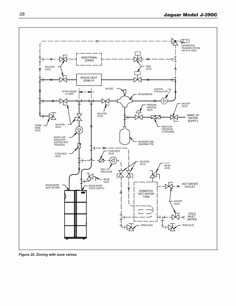
Jaguar Model J-390C28
ISOLATIONVALVE
BOILER LOOP
PURGE/
VALVEDRAIN
THE BOILER)
CIRCULATOR(SUPPLIED WITH
ISOLATIONVALVE
FLOW CHECKVALVE
ISOLATIONVALVE
DO NOT EXCEED12" APART
SPACE HEATZONE #1
ADDITIONALZONES
AIR VENT
BOILER WATERINLET (RETURN)
VALVEFLOW CHECK
RELIEFVALVE
BOILER WATEROUTLET (SUPPLY)
DHWCIRCULATOR
ZONEVALVE
(DIAPHRAM TYPE)EXPANSION TANK
T + P
VALVERELIEF
BACK FLOWPREVENTOR(IF REQUIRED)
PRESSUREREDUCINGVALVE
SHUTOFFVALVE
HOT WATEROUTLET
AIR SEPARATOR
MAKE UPWATERSUPPLY
ISOLATIONVALVE
DRAIN VALVE DRAIN VALVE
COLD
WATERINLET
TANKHOT WATERDOMESTIC
SHUTOFFVALVE
PRESSURE BYPASSVALVE (IF USED)
P
DIFFERENTIAL
SYSTEMCIRCULATOR
Figure 20. Zoning with zone valves.

Jaguar Model J-390C 29
CHILLERWATER
VALVE VALVE
UNIT
STRAINER
INLET (RETURN)BOILER WATER
CIRCULATORBOILER LOOP
VALVEISOLATION
12" APARTDO NOT EXCEED
DRAINVALVE
PURGE/
VALVESHUTOFF
VALVERELIEFT + PVALVE
ISOLATION
DRAIN VALVE
DOMESTICHOT WATER
TANK
OUTLETHOT WATER
DRAIN VALVE
INLET WATER
COLD
CIRCULATORDHW
OUTLET (SUPPLY)BOILER WATER
THE BOILER)
FLOW CHECKVALVE
(SUPPLIED WITH
VALVEISOLATION
VALVERELIEF
VALVEISOLATION
VALVEFLOW CHECK
EXPANSION TANK(DIAPHRAM TYPE)
P
VALVE
ZONESADDITIONAL
ZONE
SPACE HEATZONE #1
AIR SEPARATOR
VALVEREDUCINGPRESSURE
(IF REQUIRED)PREVENTORBACK FLOW
DIFFERENTIAL
VALVE (IF USED)PRESSURE BYPASS
SUPPLYWATER
MAKE UP
VALVESHUTOFF
ISOLATION FLOW CHECK
SYSTEMCIRCULATOR
AIR VENT
BALANCINGVALVE
Figure 21. Piping a heating-cooling system to the boiler and a chiller.
Jaguar Model J-390C30
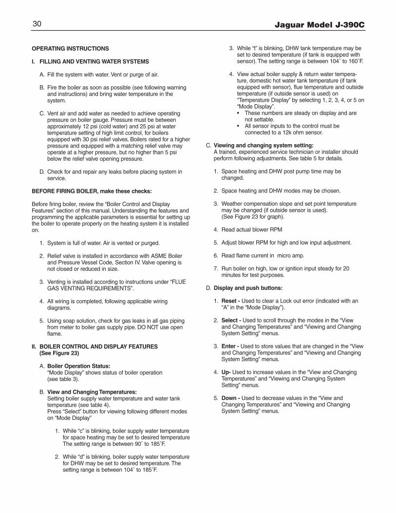
OPERATING INSTRUCTIONS
I. FILLING AND VENTING WATER SYSTEMS
A. Fill the system with water. Vent or purge of air.
B. Fire the boiler as soon as possible (see following warning and instructions) and bring water temperature in the system.
C. Vent air and add water as needed to achieve operating pressure on boiler gauge. Pressure must be between approximately 12 psi (cold water) and 25 psi at water temperature setting of high limit control, for boilers equipped with 30 psi relief valves. Boilers rated for a higherpressure and equipped with a matching relief valve may operate at a higher pressure, but no higher than 5 psi below the relief valve opening pressure.
D. Check for and repair any leaks before placing system in service.
BEFORE FIRING BOILER, make these checks:
Before firing boiler, review the “Boiler Control and Display Features” section of this manual. Understanding the features andprogramming the applicable parameters is essential for setting upthe boiler to operate properly on the heating system it is installedon.
1. System is full of water. Air is vented or purged.
2. Relief valve is installed in accordance with ASME Boiler and Pressure Vessel Code, Section IV. Valve opening is not closed or reduced in size.
3. Venting is installed according to instructions under “FLUE GAS VENTING REQUIREMENTS”.
4. All wiring is completed, following applicable wiring diagrams.
5. Using soap solution, check for gas leaks in all gas piping from meter to boiler gas supply pipe. DO NOT use open flame.
II. BOILER CONTROL AND DISPLAY FEATURES(See Figure 23)
A. Boiler Operation Status:“Mode Display” shows status of boiler operation(see table 3).
B. View and Changing Temperatures:Setting boiler supply water temperature and water tank temperature (see table 4).Press “Select” button for viewing following different modes on “Mode Display”
1. While “c” is blinking, boiler supply water temperaturefor space heating may be set to desired temperatureThe setting range is between 90˚ to 185˚F.
2. While “d” is blinking, boiler supply water temperaturefor DHW may be set to desired temperature. The setting range is between 104˚ to 185˚F.
3. While “t” is blinking, DHW tank temperature may be set to desired temperature (if tank is equipped with sensor). The setting range is between 104˚ to 160˚F.
4. View actual boiler supply & return water tempera-ture, domestic hot water tank temperature (if tank equipped with sensor), flue temperature and outsidetemperature (if outside sensor is used) on “Temperature Display” by selecting 1, 2, 3, 4, or 5 on“Mode Display”.• These numbers are steady on display and are
not settable.• All sensor inputs to the control must be
connected to a 12k ohm sensor.
C. Viewing and changing system setting:A trained, experienced service technician or installer should perform following adjustments. See table 5 for details.
1. Space heating and DHW post pump time may be changed.
2. Space heating and DHW modes may be chosen.
3. Weather compensation slope and set point temperature may be changed (if outside sensor is used). (See Figure 23 for graph).
4. Read actual blower RPM
5. Adjust blower RPM for high and low input adjustment.
6. Read flame current in micro amp.
7. Run boiler on high, low or ignition input steady for 20 minutes for test purposes.
D. Display and push buttons:
1. Reset - Used to clear a Lock out error (indicated with an “A” in the “Mode Display”).
2. Select - Used to scroll through the modes in the “View and Changing Temperatures” and “Viewing and Changing System Setting” menus.
3. Enter - Used to store values that are changed in the “Viewand Changing Temperatures” and “Viewing and Changing System Setting” menus.
4. Up- Used to increase values in the “View and Changing Temperatures” and “Viewing and Changing System Setting” menus.
5. Down - Used to decrease values in the “View and Changing Temperatures” and “Viewing and Changing System Setting” menus.

Jaguar Model J-390C 31
"TEMPERATURE" DISPLAY (3 DIGITS)
"UP" PUSH BUTTON
"DOWN" PUSH BUTTON
"ENTER" PUSH BUTTON
"SELECT" PUSH BUTTON
"BURNER STATUS"STEADY DOT = BURNER ON
BLINKING DOT = BURNER OFF
"MODE" DISPLAY
"RESET" PUSH BUTTON
Figure 22. Display Board
MODEDISPLAY
DESCRIPTION & TEMPERATURE DISPLAY
Boiler is on stand-by mode.Temperature display shows supply water Temp.
Space heating mode.Temperature display shows supply water Temp.
Domestic hot water mode.Temperature display shows supply water Temp.
Frost protection mode. **Temperature display shows supply water Temp.
Lockout (Alarm) condition.Temperature Display indicates the lockout code
Reset button must be pressed to resume normal operation.
Error Condition. *Temperature display indicates the error code.
Warning Condition. ***Temperature display indicates the error code.
NOTE: Blinking dot on “Mode Display” indicates active heating control, burner off.Steady dot indicates burner is on.
*: Error must be corrected to resume boiler operation. Pressing the “Reset” button is not required.
**: The boiler loop circulator is energized, if the boiler water temperature drops below 50˚F.
***: Error must be corrected to resume DHW operation. Space heating not affected. Pressingthe “Reset” button is not required.
Table 3
JAGUAR BOILER DISPLAY BOARD“Boiler Operation Status”
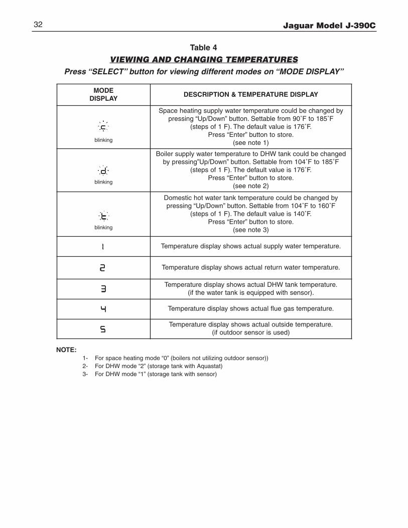
Jaguar Model J-390C32
MODEDISPLAY
DESCRIPTION & TEMPERATURE DISPLAY
Space heating supply water temperature could be changed bypressing “Up/Down” button. Settable from 90˚F to 185˚F
(steps of 1 F). The default value is 176˚F.Press “Enter” button to store.
(see note 1)
Boiler supply water temperature to DHW tank could be changedby pressing”Up/Down” button. Settable from 104˚F to 185˚F
(steps of 1 F). The default value is 176˚F.Press “Enter” button to store.
(see note 2)
Domestic hot water tank temperature could be changed by pressing “Up/Down” button. Settable from 104˚F to 160˚F
(steps of 1 F). The default value is 140˚F.Press “Enter” button to store.
(see note 3)
Temperature display shows actual supply water temperature.
Temperature display shows actual return water temperature.
Temperature display shows actual DHW tank temperature.(if the water tank is equipped with sensor).
Temperature display shows actual flue gas temperature.
Temperature display shows actual outside temperature.(if outdoor sensor is used)
NOTE:1- For space heating mode “0” (boilers not utilizing outdoor sensor))2- For DHW mode “2” (storage tank with Aquastat)3- For DHW mode “1” (storage tank with sensor)
Table 4
VIEWING AND CHANGING TEMPERATURESPress “SELECT” button for viewing different modes on “MODE DISPLAY”
blinking
blinking
blinking
Jaguar Model J-390C 33
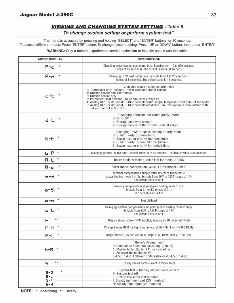
MODE DISPLAY DESCRIPTION
Changing space heating post pump time. Settable from 10 to 900 seconds.(steps of 10 seconds). The default value is 30 seconds.
Changing DHW post pump time. Settable from 1 to 255 seconds.(steps of 1 seconds). The default value is 15 seconds.
Changing space heating control mode0: Thermostat only (default) - boiler without outdoor sensor1: Outside sensor and Thermostat2: Outside sensor only3: Permanent heat demand (boiler circulator always on)4: Analog (0-10 V dc) input, 0-10 V controls water supply temperature set point of the boiler.5: Analog (0-10 V dc) input, 0-10 V controls input rate, Use this option in comjunction with
Tekamr control 265 or 275.
Changing domestic hot water (DHW) mode0: No DHW1: Storage tank with sensor2: Storage tank with thermostat (default value)
Changing DHW or space heating priority mode0: DHW priority (no time limit)1: Space heating priority (no time limit)2: DHW priority for limited time (default)3: Space heating priority for limited time
Changing priority limited time. Settable from 20 to 80 minutes. The default value is 30 minutes.
Boiler model selection, value is 5 for model J-390C
Boiler model confirmation, value is 5 for model J-390C
Weather compensation supply water reference temperature(space heating mode 1 or 2). Settable from 16°F to 122°F (steps of 1 F).
The default value is 86°F.
Changing compensation slope (space heating mode 1 or 2).Settable from 0.1 to 5.0 (steps of 0.1).
The default value is 1.0.
Not Utilized
Changing weather compensation set point (space heating mode 2 only).Settable from 32°F to 122°F (steps of 1°F).
The default value is 68°F.
Display shows blower RPM (mutiply reading by 10 for actual RPM)
Change blower RPM for high input (steps of 30 RPM, limit +/- 480 RPM).
Change blower RPM for low input (steps of 30 RPM, limit +/- 120 RPM).
“Boiler’s Assignment”0: Standalone boiler, no cascading (default)1: Master boiler (boiler #1) for cascading2: Follower boiler (boiler #2)3,4,5,6,7 & 8: Follower boilers (boiler #3,4,5,6,7 & 8)
Display shows flame current in micro amps
System test – Display shows flame current0: System test offL: Steady low input (20 minutes)I: Steady ignition input (20 minutes)H: Steady high input (20 minutes)
NOTE: *: Alternating **: Steady
VIEWING AND CHANGING SYSTEM SETTING - Table 5“To change system setting or perform system test”
The menu is accessed by pressing and holding “SELECT” and “ENTER” buttons for 10 seconds.To access different modes: Press “ENTER” button. To change system setting: Press “UP or DOWN” button, then press “ENTER”
WARNING: Only a trained, experienced service technician or installer should use this table.
*
*
*
*
*
*
*
*
*
*
*
*
**
*
*
**
*
*
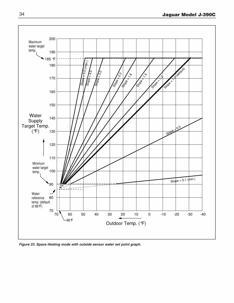
Jaguar Model J-390C34
7070 60 -20-10 -3001020304050
Outdoor Temp. (°F)
WaterSupply
Target Temp.(°F)
185 °F
140
150
130
190
180
170
160
120
110
100
80
90
200
Slo
pe =
4.0
Slo
pe =
3.0
Slope = 0.1 (min.)
Slo
pe =
2.0
Slope = 0.5
Slo
pe =
1.2
Slo
pe =
5.0
(m
ax.)
-40
Slo
pe =
1.5
Slope
= 1
.0 (d
efau
lt)
Slo
pe
= 1
.8
Maximum water targettemp.
Water referencetemp. (defaultof 86°F)
Minimum water targettemp.
68°F
Figure 23. Space Heating mode with outside sensor water set point graph.

Jaguar Model J-390C 35
III. INITIAL START
Safe lighting and other performance criteria were met when testingvarious gas manifold and control assemblies used on the JaguarJ-390C boiler under the ANSI Z21.13 - latest edition.
InstructionsFollow the lighting instructions in this manual. These instructionsare also attached to the boiler.
SAFETY INFORMATIONFor Your Safety Read Before Operating
WARNING: If you do not follow these instructions exactly, a fireor explosion may result causing property damage, personalinjury or loss of life.
A. This appliance does not have a pilot. It is equipped withan ignition device which automatically lights the burner.DO NOT try to light the burner by hand.
B. BEFORE OPERATING smell all around the appliance areafor gas. Be sure to smell next to the floor because some gasis heavier than air and will settle on the floor.
WHAT TO DO IF YOU SMELL GAS:• DO NOT try to light any appliance.• DO NOT touch any electric switch: DO NOT use any
phone in your building.• Immediately call you gas supplier from a neighbor’s
phone. Follow the gas supplier’s instructions.• If you cannot reach your gas supplier, call the fire
department.
C. Use only your hand to turn the gas supply shut-off valve. Never use tools. If the supply shut-off valve will not turn by hand, don’t try to repair it, call a qualified service technician.Force or attempted repair may result in a fire or explosion.
D. DO NOT use this appliance if any part has been under water. Immediately call a qualified service technician to inspect the appliance and to replace any part of the control system and any gas control which has been under water.
1. STOP! Read the safety information above.
2. Set the thermostat to lowest setting.
3. Turn off all electric power to the appliance.
4. This appliance is equipped with an ignition device whichautomatically lights the burner. DO NOT try to light the burner by hand.
5. Open the gas supply shut-off valve, by turning the handle tobe parallel to the gas piping (See Figure 24).
6. Wait five (5) minutes (longer for propane) to clear out any gas, then smell for gas, including near the floor. If you then smell gas, STOP! Follow “B” in the safety information above on this page. If you don’t smell gas, go to next step.
7. Turn on all electric power to the appliance.
8. Set thermostat to desired setting.If the appliance will not operate, follow the instructions“To Turn Off Gas to Appliance” and call your service technician or gas supplier.
TO TURN OFF GAS TO APPLIANCE
1. Set thermostat to lowest setting.
2. Turn off all electric power to the appliance if service is to be performed.
3. Close the gas supply shut off valve, by turning the handle to be perpendicular to the gas piping. (See Figure 24).
GAS SUPPLY SHUTOFF VALVE IN "OPEN" POSITION
GAS SUPPLY SHUTOFF VALVE IN "CLOSED" POSITION
TURN 90˚TO CLOSE
TURN 90˚TO OPEN
Figure 24. Gas supply shutoff valve operation.
OPERATING INSTRUCTIONS
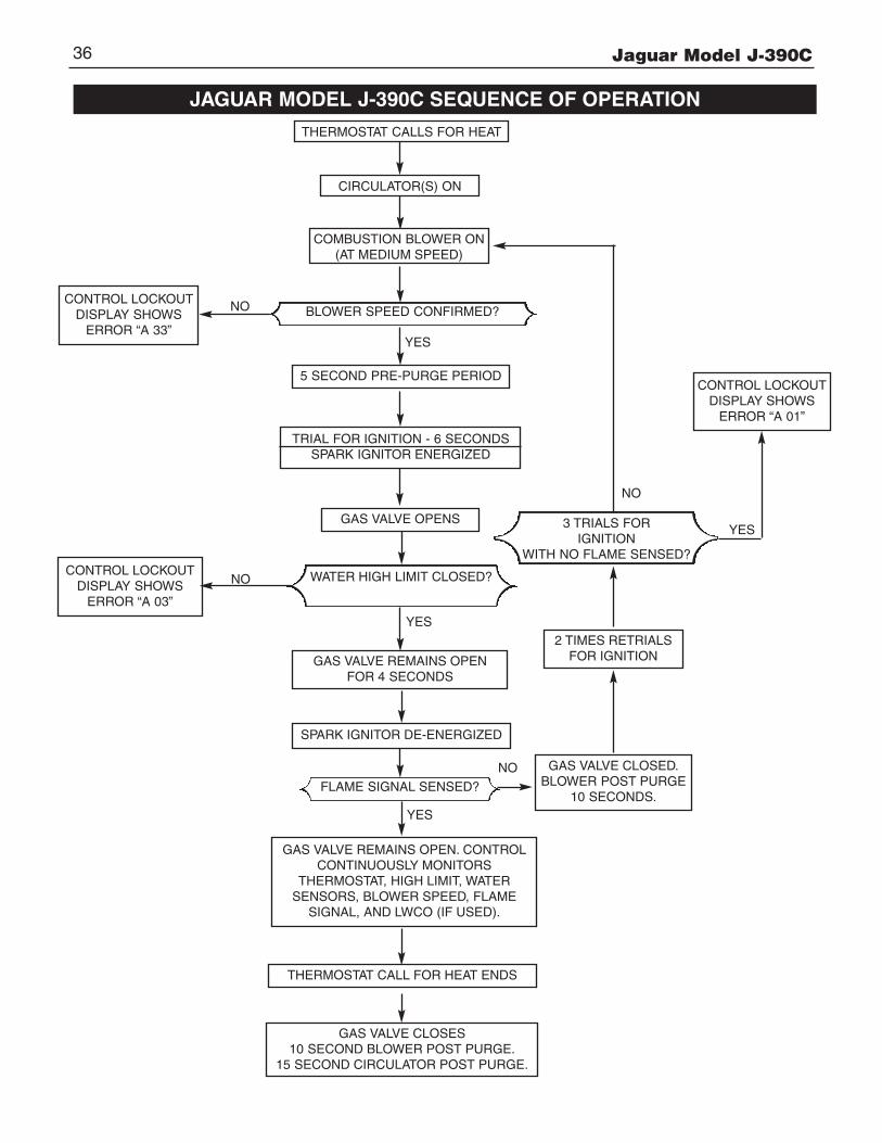
Jaguar Model J-390C36
THERMOSTAT CALLS FOR HEAT
CIRCULATOR(S) ON
5 SECOND PRE-PURGE PERIOD
JAGUAR MODEL J-390C SEQUENCE OF OPERATION
BLOWER SPEED CONFIRMED?
GAS VALVE OPENS
GAS VALVE REMAINS OPEN. CONTROLCONTINUOUSLY MONITORS
THERMOSTAT, HIGH LIMIT, WATER SENSORS, BLOWER SPEED, FLAME
SIGNAL, AND LWCO (IF USED).
THERMOSTAT CALL FOR HEAT ENDS
GAS VALVE CLOSES10 SECOND BLOWER POST PURGE.
15 SECOND CIRCULATOR POST PURGE.
CONTROL LOCKOUTDISPLAY SHOWSERROR “A 33”
YES
NO
NO
COMBUSTION BLOWER ON(AT MEDIUM SPEED)
TRIAL FOR IGNITION - 6 SECONDSSPARK IGNITOR ENERGIZED
WATER HIGH LIMIT CLOSED?
YES
GAS VALVE REMAINS OPENFOR 4 SECONDS
SPARK IGNITOR DE-ENERGIZED
FLAME SIGNAL SENSED?
YES
3 TRIALS FOR IGNITION
WITH NO FLAME SENSED?
2 TIMES RETRIALSFOR IGNITION
GAS VALVE CLOSED.BLOWER POST PURGE
10 SECONDS.
NO
CONTROL LOCKOUTDISPLAY SHOWSERROR “A 01”
YES
CONTROL LOCKOUTDISPLAY SHOWSERROR “A 03”
NO
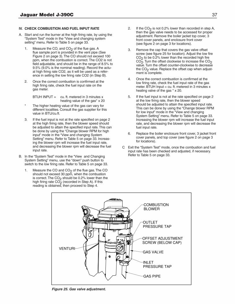
Jaguar Model J-390C 37
IV. CHECK COMBUSTION AND FUEL INPUT RATE
A. Start and run the burner at the high firing rate, by using the “System Test” mode in the “View and changing systemsetting” menu. Refer to Table 5 on page 33.
1. Measure the CO, and CO2 of the flue gas. A flue sample port is provided in the vent pipe (See Figure 2 on page 3). The CO should not exceed 100 ppm, when the combustion is correct. The CO2 is not field adjustable, and should be in the range of 8.5% to 9.5% (9.0% is the nominal reading). Record the actu-al high firing rate CO2, as it will be used as a refer-ence in setting the low firing rate CO2 (in Step B).
2. Once the correct combustion is confirmed at the high firing rate, check the fuel input rate on the gas meter.
BTUH INPUT = cu. ft. metered in 3 minutes x heating value of the gas* x 20
* The higher heating value of the gas can vary for different localities. Consult the gas supplier for this value in BTU/cu.ft.
3. If the fuel input is not at the rate specified on page 2 at the high firing rate, then the blower speed should be adjusted to attain the specified input rate. This can be done by using the “Change blower RPM for high input” mode in the “View and changing SystemSetting” menu. Refer to Table 5 on page 33. Increas-ing the blower rpm will increase the fuel input rate, and decreasing the blower rpm will decrease the fuel input rate.
B. In the “System Test” mode in the “View and Changing System Setting” menu, use the “down” push button to switch to the low firing rate. Refer to Table 5 on page 33.
1. Measure the CO and CO2 of the flue gas. The CO should not exceed 30 ppm, when the combustion is correct. The CO2 should be 0.2% lower than the high firing rate CO2 (recorded in Step A). If thisreading is obtained, then proceed to Step 4.
2. If the CO2 is not 0.2% lower than recorded in step A, then the gas valve needs to be accessed for proper adjustment. Remove the boiler jacket top cover, 3 front cover panels, and enclosure front cover(see figure 2 on page 3 for locations).
3. Remove the cap that covers the gas valve offset screw (see figure 25 for location). Adjust the low fire CO2 to be 0.2% lower than the recorded high fire CO2. Turn the offset clockwise to increase the CO2value. Turn the offset counter-clockwise to decrease the CO2 value. Replace the offset cap when adjust-ment is complete.
4. Once the correct combustion is confirmed at the low firing rate, check the fuel input rate of the gas meter. BTUH Input = cu. ft. metered in 3 minutes x heating valve of the gas * x 20.
5. If the fuel input is not at the rate specified on page 2 at the low firing rate, then the blower speed should be adjusted to attain the specified input rate. This can be done by using the “Change blower RPM for low input” mode in the “View and changing System Setting” menu. Refer to Table 5 on page 33. Increasing the blower rpm will increase the fuel input rate, and decreasing the blower rpm will decrease thefuel input rate.
6. Replace the boiler enclosure front cover, 3 jacket front cover panels, and top cover (see figure 2 on page 3 for locations).
C Exit the “System Test” mode, once the combustion and fuel input rate has been checked and adjusted, if necessary. Refer to Table 5 on page 33.
INLETPRESSURE TAP
OUTLET PRESSURE TAP
GAS VALVEVENTURI
COMBUSTIONBLOWER
GAS PIPE
OFFSET ADJUSTMENTSCREW (BELOW CAP)
Figure 25. Gas valve adjustment.
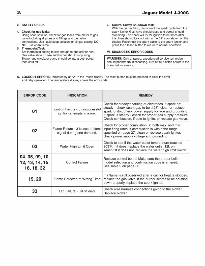
Jaguar Model J-390C38
V. SAFETY CHECK
A. Check for gas leaks:Using soap solution, check for gas leaks from meter to gas valve including all pipes and fittings and gas valve connections. Use liquid soap solution for all gas testing. DONOT use open flame.
B. Thermostat Test:Set thermostat setting to low enough to end call for heat. Gas valve should close and burner should stop firing. Blower and circulator pump should go into a post purge, then shut off.
C. Control Safety Shutdown test:With the burner firing, disconnect the spark cable from the spark ignitor. Gas valve should close and burner should stop firing. The boiler will try for ignition three times after this, then should lock out with an “A 01” error shown on thedisplay. Reconnect the spark cable to the spark ignitor, and press the “Reset” button to return to normal operation.
VI. DIAGNOSTIC ERROR CODES
WARNING: Only a trained, experienced service technicianshould perform troubleshooting. Turn off all electric power to theboiler before service.
A. LOCKOUT ERRORS: Indicated by an “A” in the mode display. The reset button must be pressed to clear the error and retry operation. The temperature display shows the error code.
ERROR CODE INDICATION REMEDY
01 Ignition Failure - 3 unsuccessful ignition attempts in a row.
Check for steady sparking at electrodes. If spark notsteady - check spark gap to be .125”, clean or replacespark ignitor, check power supply voltage and grounding.If spark is steady - check for proper gas supply pressure.Check combustion, if able to ignite, or replace gas valve.
02 Flame Failure - 3 losses of flamesignal during one demand.
Check for proper combustion, at both max. and min.input firing rates. If combustion is within the range specified on page 37, clean or replace spark ignitor,check power supply voltage and grounding.
03 Water High Limit OpenCheck to see if the water outlet temperature reaches203˚F. If it does, replace the water outlet 12k ohm sensor. If it does not, replace the water high limit switch.
04, 05, 09, 10, 12, 13, 14, 15, 16, 18, 32
Control FailureReplace control board. Make sure the proper boilermodel selection and confirmation code is entered.See Table 5 on page 33.
19, 20 Flame Detected at Wrong TimeIf a flame is still observed after a call for heat is stopped,replace the gas valve. If the burner seems to be shuttingdown properly, replace the spark ignitor.
33 Fan Failure - RPM errorCheck wire harness connections going to the blower.Replace blower.
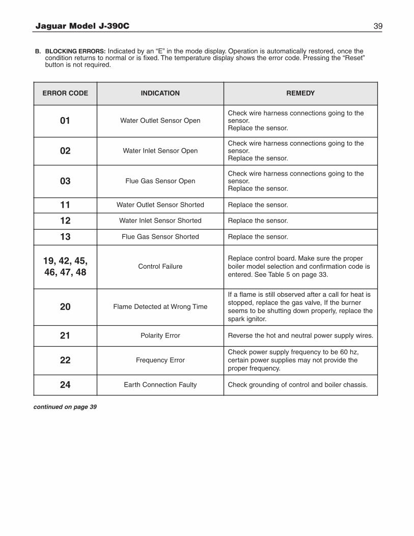
Jaguar Model J-390C 39
B. BLOCKING ERRORS: Indicated by an “E” in the mode display. Operation is automatically restored, once the condition returns to normal or is fixed. The temperature display shows the error code. Pressing the “Reset” button is not required.
ERROR CODE INDICATION REMEDY
01 Water Outlet Sensor OpenCheck wire harness connections going to thesensor.Replace the sensor.
02 Water Inlet Sensor OpenCheck wire harness connections going to thesensor.Replace the sensor.
03 Flue Gas Sensor OpenCheck wire harness connections going to thesensor.Replace the sensor.
11 Water Outlet Sensor Shorted Replace the sensor.
12 Water Inlet Sensor Shorted Replace the sensor.
13 Flue Gas Sensor Shorted Replace the sensor.
19, 42, 45,46, 47, 48
Control FailureReplace control board. Make sure the properboiler model selection and confirmation code isentered. See Table 5 on page 33.
20 Flame Detected at Wrong Time
If a flame is still observed after a call for heat isstopped, replace the gas valve, If the burnerseems to be shutting down properly, replace thespark ignitor.
21 Polarity Error Reverse the hot and neutral power supply wires.
22 Frequency ErrorCheck power supply frequency to be 60 hz, certain power supplies may not provide the proper frequency.
24 Earth Connection Faulty Check grounding of control and boiler chassis.
continued on page 39
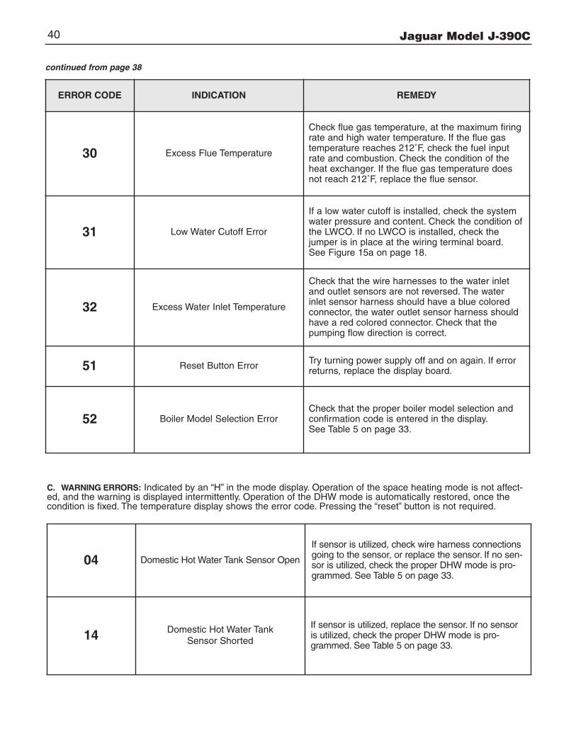
Jaguar Model J-390C40
ERROR CODE INDICATION REMEDY
30 Excess Flue Temperature
Check flue gas temperature, at the maximum firing rate and high water temperature. If the flue gas temperature reaches 212˚F, check the fuel input rate and combustion. Check the condition of the heat exchanger. If the flue gas temperature does not reach 212˚F, replace the flue sensor.
31 Low Water Cutoff Error
If a low water cutoff is installed, check the system water pressure and content. Check the condition of the LWCO. If no LWCO is installed, check the jumper is in place at the wiring terminal board. See Figure 15a on page 18.
32 Excess Water Inlet Temperature
Check that the wire harnesses to the water inlet and outlet sensors are not reversed. The water inlet sensor harness should have a blue colored connector, the water outlet sensor harness should have a red colored connector. Check that the pumping flow direction is correct.
51 Reset Button Error Try turning power supply off and on again. If error returns, replace the display board.
52 Boiler Model Selection ErrorCheck that the proper boiler model selection and confirmation code is entered in the display.See Table 5 on page 33.
continued from page 38
04 Domestic Hot Water Tank Sensor Open
If sensor is utilized, check wire harness connectionsgoing to the sensor, or replace the sensor. If no sen-sor is utilized, check the proper DHW mode is pro-grammed. See Table 5 on page 33.
14 Domestic Hot Water TankSensor Shorted
If sensor is utilized, replace the sensor. If no sensoris utilized, check the proper DHW mode is pro-grammed. See Table 5 on page 33.
C. WARNING ERRORS: Indicated by an “H” in the mode display. Operation of the space heating mode is not affect-ed, and the warning is displayed intermittently. Operation of the DHW mode is automatically restored, once thecondition is fixed. The temperature display shows the error code. Pressing the “reset” button is not required.
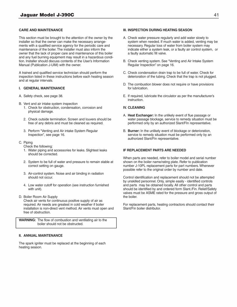
Jaguar Model J-390C 41
CARE AND MAINTENANCE
This section must be brought to the attention of the owner by theinstaller so that the owner can make the necessary arrange-ments with a qualified service agency for the periodic care andmaintenance of the boiler. The installer must also inform theowner that the lack of proper care and maintenance of this boilerand any fuel burning equipment may result in a hazardous condi-tion. Installer should discuss contents of the User’s InformationManual (Publication J-UIM) with the owner.
A trained and qualified service technician should perform theinspection listed in these instructions before each heating seasonand at regular intervals.
I. GENERAL MAINTENANCE
A. Safety check, see page 38.
B. Vent and air intake system inspection1. Check for obstruction, condensation, corrosion and
physical damage.
2. Check outside termination. Screen and louvers should be free of any debris and must be cleaned as required.
3. Perform “Venting and Air intake System RegularInspection”, see page 16.
C. PipingCheck the following:1. Water piping and accessories for leaks. Slightest leaks
should be corrected.
2. System to be full of water and pressure to remain stable atcorrect setting on gauge.
3. Air-control system. Noise and air binding in radiation should not occur.
4. Low water cutoff for operation (see instruction furnished with unit).
D. Boiler Room Air SupplyCheck air vents for continuous positive supply of air as required. Air needs are greatest in cold weather if boiler installation is non-direct vent method. Air vents must open andfree of obstruction.
WARNING: The flow of combustion and ventilating air to the boiler should not be obstructed.
II. ANNUAL MAINTENANCE
The spark igniter must be replaced at the beginning of eachheating season.
III. INSPECTION DURING HEATING SEASON
A. Check water pressure regularly and add water slowly to system when needed. If much water is added, venting may benecessary. Regular loss of water from boiler system may indicate either a system leak, or a faulty air control system, ora faulty automatic fill valve.
B. Check venting system. See “Venting and Air Intake System Regular Inspection” on page 16.
C. Check condensation drain trap to be full of water. Check for deterioration of the tubing. Check that the trap is not plugged.
D. The combustion blower does not require or have provisions for lubrication.
E. If required, lubricate the circulator as per the manufacturer’s instruction.
IV. CLEANING
A. Heat Exchanger: In the unlikely event of flue passage or water passage blockage, service to remedy situation must be performed only by an authorized Slant/FIn representative.
B. Burner: In the unlikely event of blockage or deterioration, service to remedy situation must be performed only by an authorized Slant/Fin representative.
IF REPLACEMENT PARTS ARE NEEDED
When parts are needed, refer to boiler model and serial numbershown on the boiler name/rating plate. Refer to publication number J-10PL replacement parts for part numbers. Wheneverpossible refer to the original order by number and date.
Control identification and replacement should not be attemptedby unskilled personnel. Only, simple easily - identified controlsand parts may be obtained locally. All other control and partsshould be identified by and ordered form Slant./Fin. Relief/Safetyvalves must be ASME rated for the pressure and gross output ofthe boiler.
For replacement parts, heating contractors should contact theirSlant/Fin boiler distributor.

Jaguar Model J-390C42
GENERAL TROUBLESHOOTING GUIDE FOR SERVICE PERSONNEL
WARNING: Only a trained, experienced service technician should perform troubleshooting. Turn off all electrical power to the boiler before servicing.
A. BURNER FAILS TO OPERATE - NO HEAT
CAUSE REMEDY
1. No power, display off, power switch off. Main electric 1. Close switch. Check or replace fuse.switch open. Blown or defective line fuse.
2. Gas supply valve shut off. 2. Open gas supply valve. Check gas pressure.
3. Harnesses plug-in connectors are not securely connected. 3. Check connectors on boiler control.
4. Operational problem, detected by control. 4. Error code on display can be correlated to specific problems and remedy. Refer to page 38-40 for error codes.
B. NOT ENOUGH HEAT
1. Thermostat setting is too low. 1. Set thermostat at higher setting.
2. Boiler water maintained at too low temperature. 2. Increase space heating set point temperature.Refer to Table 4 on page 32.
3. Circulator not running. 3. With thermostat calling for heat, check for power to circulator. If power is O.K. but circulator is not running, replace circulator.
4. Boiler water level too low. 4. Carefully snap open relief valve handle to determine if boiler is full of water, if not full of water, check for system leaks and check water pressure regulator. Repair any system leaks. Adjust or replace water pressure reducing valve.
5. Fuel input rate too low. 5. Check the maximum fuel input firing rate.Refer to page 37 for the procedure.
C. FUMES AND GAS ODORS
1. Leaks in gas piping or accessories. 1. Locate leaks and repair.
2. Gas leaks in service line or meter connections. 2. Close service supply valve - shut down boiler and notify utility.
3. Condensation traps are not full of water. 3. Check and fill with water
4. Venting system is physically damaged. 4. Check carefully and repair. Also, see “Venting System Regular Inspection”.
5. Over - firing or poor combustion. 5. Check the maximum fuel input firing rate and combustion. Refer to page 37 for procedure.

Jaguar Model J-390C 43
NOTES

SLANT/FIN CORPORATION, Greenvale, N.Y. 11548 • Phone: (516) 484-2600FAX: (516) 484-5921 • Canada: Slant/Fin LTD/LTEE, Mississauga, Ontario
www.slantfin.com©Slant/Fin Corp. 2010


![New NAVAIR Wiring System Initiatives.ppt [Read-Only] · 2002. 12. 10. · • NAVAIR maintains 38 Wiring ProductQPLs covering contacts, connectors, wires, terminals, tools, circuit](https://img.pdfslide.net/doc/110x75/60676ad9c1c0073eb34a79c6/new-navair-wiring-system-read-only-2002-12-10-a-navair-maintains-38-wiring.jpg)