Embed Size (px)
Citation preview

1
WARNING: If the information in this manual is not followed exactly, a fire or explosion may result causing property damage, personal injury or loss of life.
— Do not store or use gasoline or other flammable vapors and liquids in the vicinity of this or any other appliance.
— WHAT TO DO IF YOU SMELL GAS:
• Do not try to light any appliance. • Do not touch any electrical switch; do
not use any phone in your building. • Immediately call your gas supplier
from a neighbor’s phone. Follow the gas supplier’s instructions.
• If you cannot reach your gas supplier, call the fire department.
— Installation and service must be performed by a qualified installer, service agency or the gas supplier.
PRINTED 0911 320856-001
INSTRUCTION MANUALMODELS:
VB/VW-500, 750 AND 1000SERIES 200/201
GAS-FIRED COPPER BOILERS FOR HYDRONIC HEATING AND HOT WATER SUPPLY
• Installation• Operation• Maintenance• Limited Warranty
MC BEE, SC., RENTON, WA.,STRATFORD-ONTARIO, VELDHOVEN-THE NETHERLANDS,
NANJING, CHINAwww.hotwater.com / email: [email protected]

2
SAFE INSTALLATION, USE AND SERVICEThe proper installation, use and servicing of this boiler is extremely important to your safety and the safety of others.
Many safety-related messages and instructions have been provided in this manual and on your boiler to warn you and others of a potential injury hazard. Read and obey all safety messages and instructions throughout this manual. It is very important that the meaning of each safety message is understood by you and others who install, use, or service this boiler.
DANGER indicates an imminentlyhazardous situation which, if not avoided,will result in injury or death.
This is the safety alert symbol. It is used to alert you topotential personal injury hazards. Obey all safetymessages that follow this symbol to avoid possibleinjury or death.
WARNING indicates a potentially hazardoussituation which, if not avoided, could resultin injury or death.
CAUTION indicates a potentially hazardoussituation which, if not avoided, could result inminor or moderate injury.
CAUTION used without the safety alertsymbol indicates a potentially hazardoussituation which, if not avoided, could result inproperty damage.
WARNING
CAUTION
CAUTION
DANGER
All safety messages will generally tell you about the type of hazard, what can happen if you do not follow the safety message, and how to avoid the risk of injury.
The California Safe Drinking Water and Toxic Enforcement Act requires the Governor of California to publish a list of substances known to the State of California to cause cancer, birth defects, or other reproductive harm, and requires businesses to warn of potential exposure to such substances.
This product contains a chemical known to the State of California to cause cancer, birth defects, or other reproductive harm. This appliance can cause low level exposure to some of the substances listed in the Act.
IMPORTANT DEFINITIONS• Qualified Installer: A qualified installer must have ability equivalent to a licensed tradesman in the fields of plumbing,
air supply, venting and gas supply, including a thorough understanding of the requirements of the National Fuel Gas Codeasitrelatestotheinstallationofgasfiredboilers.Thequalifiedinstallermusthaveathoroughunderstandingofthisinstructionmanual.
• Service Agency: A service agency also must have ability equivalent to a licensed tradesman in the fields of plumbing, air supply, venting and gas supply, including a thorough understanding of the requirements of the National Fuel Gas Code as it relates to the installation of gas fired boilers. The service agency must also have a thorough understanding of this instruction manual, and be able to perform repairs strictly in accordance with the service guidelines provided by the manufacturer.
• Gas Supplier: The Natural Gas or Propane Utility or service who supplies gas for utilization by the gas burning appliances within this application. The gas supplier typically has responsibility for the inspection and code approval of gas piping up to and including the Natural Gas meter or Propane storage tank of a building. Many gas suppliers also offer service and inspection of appliances within the building.

3
GENERAL SAFETY

4
Minimum clearances to combustibles:•4”(102mm)rear•0”(0mm)top&sides•6”(152mm)vent
TABLE 1. - GAS AND ELECTRICAL CHARACTERISTICS Manifold Pressure Maximum Supply Pressure Minimum Supply Pressure Model Type of Gas Inches W.C. kPa Inches W.C. kPa Inches W.C. kPa VB/VW-500, 750, 1000 NATURAL -2 to -3.5 -.5 to .9 14 3.44 4.0 2.0 VB/VW-500, 750, 1000 PROPANE -2 to -3.5 -.5 to .9 14 3.44 8.0 2.0
Minimum Pressures must be maintained during all operating conditions.Electrical Power: 120v, 60hz, and 30 amps.
Models VB/VW-500 VB/VW-750 VB/VW-1000 Dimensions inches mm inches mm inches mm Flue Outlet Diameter 6 152 6 152 6 152
Air Intake Diameter 4 102 4 102 4 102
Water Inlet 2”NPT
Water Outlet 2”NPT
Gas Inlet 1”NPT
A 56 1422 62 1575 71 1803
B 30 762 30 762 30 762
C 30 762 30 762 30 762
D 45 1143 51 1295 59 1499
E 36 914 42 1067 48 1219
F 16.5 419 16.5 419 16.5 419
G 8 203 8 203 8 203
H 15 381 15 381 15 381
J 9 229 9 229 9 229
K 11.5 292 11.5 292 11.5 292
L 11 279 11 279 11 279
M 10.5 267 10.5 267 10.5 267
N 33 838 33 838 33 838
P 31 787 31 787 31 787
DIMENSION AND CAPACITY DATA
TABLE 2. - ROUGH-IN DIMENSIONS
FIGURE 1.

5
CAPACITY AND FLOW DATA
TABLE 3. RECOVERY CAPACITIES.
TABLE 4. PUMPING PERFORMANCE GUIDE. VB MODELS - FLOW, HEAD LOSS AND TEMPERATURE RISE
20F° (11°C) t 30F° (17°C) t 40F° (22°C) t Maximum Flow Rate Minimum Flow Rate
MODEL GPM LPH P FT P m GPM LPH P FT P m GPM LPH P FT P m GPM LPH P FT P m T °F T °C GPM LPH P FT P m T °F T °C
VB-500 42 159 1.8 0.5 28 106 1.3 0.4 21 79 1.0 0.3 100 379 3.8 1.2 8 4 21 79 1.0 0.3 40 22
VB-750 63 238 2.9 0.9 42 159 2.1 0.6 32 121 1.8 0.5 110 416 4.3 1.3 12 7 32 121 1.8 0.5 40 22
VB-1000 85 322 3.9 1.2 56 212 2.8 0.9 42 159 2.3 0.7 120 454 4.9 1.5 14 8 42 159 2.3 0.7 40 22
Model No.
Input Rating Btu/hr
Output Rating Btu/hr
Water Flow
TemperatureRise-°F(°C)40 60 80 90 100 120 140(22) (33) (44) (90) (56) (67) (78)
VW-500 500,000 421,500 GPH 1,268 845 634 563 507 423 362LPH 4,797 3,198 2,399 2,132 1,919 1,599 1,371
VW-700 750,000 633,750 GPH 1,901 1,268 951 845 761 634 543LPH 7,196 4,797 3,598 3,198 2,878 2,399 2,056
VW-1000 1,000,000 845,000 GPH 2,535 1,690 1,268 1,127 1,014 845 724LPH 9,595 6,397 4,797 4,264 3,838 3,198 2,741

6
This design complies with the current edition of the ANSI Z21.13 low-pressure boiler standard.Compliance under this standard implies that when the boiler underwent test, the gas manifold and control assembly pro vided on the boiler met safe lighting and other performance criteria.Detailed installation diagrams are found in this manual. These diagrams will serve to provide the installer a reference for the materials and methods of piping necessary. It is essential that all water, gas piping and wiring be installed as shown on the diagrams. You should thoroughly read and understand this manual before installation and/or operation of this boiler.The factory warranty will be void if the boiler(s) have beenimproperly installed or operated.
AL 29-4C® is a registered trademark of Allegheny Ludlum Corporation.Inadditiontotheseinstructions,theboiler(s)shallbeinstalledinaccordance with those installation regulations in force in the local area where the installation is to be made. These shall be carefully followed in all cases. Authorities having jurisdiction should be consulted before installations are made.In the absence of local codes, the installation must comply with the current editions, as follows:In the United States:The National Fuel Gas Code, ANSI Z223.1/NFPA 54 and the National Electric Code, NFPA 70.
CONTENTS
INTRODUCTION
SAFE INSTALLATION, USE AND SERVICE ...........................................2GENERAL SAFETY......................................................................................3DIMENSION AND CAPACITY DATA .........................................................4CAPACITY AND FLOW DATA ....................................................................5CONTENTS ...................................................................................................6INTRODUCTION ...........................................................................................6
Grounding Instructions .............................................................................7Inlet Water Considerations ......................................................................7Correct Gas ..............................................................................................7Precautions ...............................................................................................7Liquefied Petroleum Gas Models ..........................................................7High Altitude Installations ........................................................................7Field Installed Components ....................................................................7
CONTROL COMPONENTS .........................................................................8The Control System ................................................................................8Hot Surface Igniter ..................................................................................8Pressure Switches ...................................................................................8Low Gas Switch ......................................................................................8Water Flow Switch ..................................................................................8Flame Sensor ...........................................................................................8Water Temperature Limit Controls .........................................................9ON/OFF Switch ........................................................................................9Circulating Pump ......................................................................................9Temperature Probes ................................................................................9Low Water Cutoff (Optional) ..................................................................9Pressure Relief Valve ..............................................................................9
GENERAL ....................................................................................................10Required Ability ......................................................................................10Location ...................................................................................................10Panels and Covers ................................................................................10Chemical Vapor Corrosion .................................................................... 11Installtion Clearances ............................................................................. 11Leveling ................................................................................................... 11Air Requirements ................................................................................... 11Unconfined Space .................................................................................. 11Confined Space ..................................................................................... 11Fresh Air Openings for Confined Spaces .......................................... 11Outdoor Air Through Two Openings ...................................................12Outdoor Air Through One Opening ....................................................12Outdoor Air Through Two Horizontal Ducts .......................................12Outdoor Air Through Two Vertical Ducts ...........................................12Air From Other Indoor Spaces............................................................13Termination Clearances Sidewall Power Vent ...................................14Termination Clearances Sidewall Direct Vent ....................................15
VENTING .....................................................................................................16Special Installation Considerations .......................................................16Venting System Using AL 29-4C® .......................................................16General Exhaust Vent Installation Procedure ....................................16Connecting Vent to Boiler ....................................................................16Venting Supports ....................................................................................17Vertical Installation Requirements ........................................................17
Horizontal Installtion Requirements ......................................................17Direct Vent Installation Requirements .................................................19
INSTALLATION REQUIREMENTS FOR THE COMMONWEALTH OF MASSACHUSETTS .....................................................................................19SYSTEM INSTALLATION ..........................................................................22
General ....................................................................................................22Hot Water Heating (Hydronic) Equipment ..........................................22Internal Contaminants ............................................................................23Hot Water Supply Boiler System - General Water Line Connections ...23Hard Water Conditions ..........................................................................23Thermal Expansion (Closed System) ..................................................23Remote Probe Installation Procedure .................................................23Gas Connections ...................................................................................24Gas Supply Line Sizing ........................................................................24Wiring ......................................................................................................28
SUGGESTED PIPE SIZING TABLES .....................................................29WIRING DIAGRAM ....................................................................................30VB/VW-500, 750 & 1000 SCHEMATIC DIAGRAM ...............................32OPERATION ................................................................................................33
Important .................................................................................................33General ....................................................................................................33Filling and Purging of Heating Boiler Installation..............................33Filling Hot Water Supply Boiler Installation .......................................33Purging Gas Line ..................................................................................33Inlet Gas Pressure ................................................................................33Water Temperature Regulation .............................................................34
LIGHTING & OPERATION INSTRUCTIONS ..........................................36Adjustment ..............................................................................................37Setting of the Test Mode .....................................................................37Control System .......................................................................................37Inputs to MCB .......................................................................................38Operating Sequence ..............................................................................39UIM Operating Procedures ...................................................................40Operating Setpoint Adjustment Procedure ..........................................41High Limit Differential Setpoint Adjustment Procedure .....................42
TROUBLESHOOTING IGNITION SYSTEM ............................................44Troubleshooting Gas Valve ...................................................................45Main Burner ............................................................................................45
PREVENTATIVE MAINTENANCE .............................................................45Relief Valve ............................................................................................46Combustion Air Filter .............................................................................46Blower Compartment .............................................................................46Burner Maintenance ...............................................................................46Condensate Removal System ..............................................................46Venting Maintenance .............................................................................47Heat Exchanger Preventative Maintenance ........................................47Deliming ..................................................................................................47Tube Cleaning Procedure Mechanical Removal of Deposits ..........47Replacement Parts ................................................................................47
NOTES .........................................................................................................48LIMITED WARRANTY ................................................................................51

7
GROUNDING INSTRUCTIONSThis boiler must be grounded in accordance with the National Electrical Code and/or local codes. Boiler is polarity sensitive; correct wiring is imperative for proper operation.
This boiler must be connected to a grounded metal, permanent wiring system, or an equipment grounding conductor must be run with the circuit conductors and connected to the equipment grounding terminal or lead on the boiler.
INLET WATER CONSIDERATIONSTo minimize the amount of condensate, a minimum inlet water temperature to the heat exchanger of 120°F (49°C) shall be maintained. This temperature can be acquired by returning120°F(49°C)waterfromtheremotestoragetanktothe boiler or by installing a by-pass loop between the boil er’s inlet and outlet connec tions. When installing a by-pass loop, a remote probe MUST be used, see SYSTEM INSTALLATION.
Circulating water through the boiler and to the remote storage tank(ifapplicable)isaccomplishedbyapumponVWmodelsonly. For hot water heating systems using the VB model, the circulating pump is NOT provided on standard models (optional)andmustbefieldinstalled.
CORRECT GASMAKE SURE THE GAS ON WHICH THE BOILER WILL OPERATE IS THE SAME AS THAT SPECI FIED ON THE BOILER RATING PLATE. DO NOT INSTALL THE BOILER IF EQUIPPED FOR A DIFFERENT TYPE OF GAS — CON-SULT YOUR SUPPLIER.
PRECAUTIONSIF THE UNIT IS EXPOSED TO THE FOLLOWING, DO NOT OPERATE UNTIL ALL CORRECTIVE STEPS HAVE BEEN MADE BY A QUALIFIED SERVICE AGENT:
1. EXPOSURE TO FIRE. 2. IF DAMAGED. 3. FIRING WITHOUT WATER. 4. SOOTING.
IF THE BOILER HAS BEEN EXPOSED TO FLOODING, IT MUST BE REPLACED.
LIQUEFIED PETROLEUM GAS MODELSBoilers for propane or liquefied petroleum gas (LPG) aredifferent from natural gas models. A natural gas boiler will not function safely on LP gas and no attempt should be made to convert a boiler from natural gas to LP gas.
LP gas must be used with great caution. It is highly explosive and heavier than air. It collects first in the low areas making its odor difficult to detect at nose level. If LP gas is present or even suspected, do not attempt to find the cause yourself. Leave the building, leaving
doors open to ventilate, then call your gas supplier or service agent. Keep area clear until a service call has been made.
At times you may not be able to smell an LP gas leak. One cause is odor fade, which is a loss of the chemical odorant that gives LP gas its distinctive smell. Another cause can be your physical condition, such as having a cold or diminishing sense of smell with age. For these reasons, the use of a propane gas detector is recommended.
IF YOU EXPERIENCE AN OUT OF GAS SITUATION, DO NOT TRY TO RELIGHT APPLIANCES YOURSELF. Call your local service agent. Only trained LP professionals should conduct the required safety checks in accordance with industry standards.
HIGH ALTITUDE INSTALLATIONS
Rated inputs are suitable up to 7000 feet (2134m)elevation. Consult the factory for installation at altitudes over 7000 feet (2134m).
FIELD INSTALLED COMPONENTSWhen install ing the boiler, the follow ing compo nents MUST be installed:
1)CirculatingPump(Hydronic)
2)TankTemperatureControlProbe(HotWaterSupply)
3)RemoteTemperatureControlProbe(Hydronic)
4)StorageTankT&PReliefValve
5)ManualGasShutoffValve(Supply)
Check the FEATURES AND CONTROLS section for further information.

8
THE CONTROL SYSTEM
The control system consists of four basic components: 1) Modulation Control Board (MCB); 2) Power DistributionBoard(PDB);3)VariableFrequencyDrive(VFD),seeFigure2; User Interface Module, see Figure 20. The Modulation Control Board and the Power Distribution Board are located in the control box and can be accessed by opening the front door of the unit. The User Interface Module is attached to the front door panel. Every system will have one Modulation Control Board (MCB), one Power Distribution Board (PDB),and oneUser InterfaceModule (UIM).
TheMCBcontainsdipswitcheswhichareusedtoconfiguretheboiler for several different control options, see the Control System Section.
FIGURE 2.
HOT SURFACE IGNITER
The Hot Surface Igniter is a device that ignites the main burner by high temperature(>1800°F)[982°C],seeFigure3.Theigniterismadeof recrystallized silicon carbide, and when 120 VAC is applied to the igniter,sufficientheatisgeneratedtoignitethemainburner.Althoughimprovements have been made to strength en the igniter, it is still fragile and care must be taken in handling the igniter to prevent breakage.
FIGURE 3. FIGURE 4.
PRESSURE SWITCHES
This control system has 3 pressure switches that are standard. Blocked InletPressureSwitch(BIS),BlowerProverSwitch(BPS)BlockedFlueSwitch(BFS).
The BPS on this model is a normally open switch that closes on increased vacuum. Once the blower moves enough air to create a vacuum across theVenturitheBPSisactivated.Iftheblowerfailsorcannotmovesufficientair a soft lockout will occur. Inspect the blower for correct operation.
TheBlockedInletSwitch(BIS)willactivateistheintakeisblockedonlyduring the heating cycle. The BIS is a normally closed pressure switch that opens when the air intake is blocked. If the BIS is activated check and clear the intake of any obstructions.
Theblockedfluepressureswitch(BFS)activatedwhentheexhaust
flueoftheunitisrestrictedorblocked.TheBFSisanormallyclosedswitch that opens when positive pressure is placed on the switch because of any restriction to the exhaust venting. If the BFS is activated check and clear any obstructions causing the restriction.
LOW GAS SWITCH
This VF boiler is available with a low gas pressure switch which meets the CSD-1 code requirements, see Figure 5.
TheLowGasPressureSwitch(LGPS)isnormallyclosedandremainsclosed unless the pressure falls below the preset pressure.
FIGURE 5. LOW GAS PRESSURE SWITCH.
WATER FLOW SWITCH
The water flow switch is installed at the boiler outlet topreventburneroperationintheeventofinadequatewaterflowthrough the boiler. It is a normally open switch that will close itscontactswhen increasingwaterflowrate isdetected.Thewaterflowswitch is factory-set.Thecontactswillopenwhentheflowratedropsbelow the factorysettingcausing thegasvalve to close which will turn off the gas to the burner, see Figure 6. Under no circumstances shall the flow switch betampered with or bypassed. Doing so may cause damage to the heat exchanger not covered under the warranty.
FIGURE 6. WATER FLOW SWITCH.
FLAME SENSOR
EachBoilerisequippedwithtwoflamesenorscoupledtogethertodetectthepresenceoftheburnerflamesathighandlowfireconditions.Theseflamesensorsworktogetherasonetosensethe flame. If no flame is sensed, the gas valve(s) will closeautomatically.Ifnoflameissensedonthreeignitiontrials,theboilerwill lock out. In the event of a lockout, depress the SELECT button on the display board to restart the boiler.
CONTROL COMPONENTS

9
WATER TEMPERATURE LIMIT CONTROLS
The“V(B/W)”modelsincorporateanoutletwaterprobeconsistingof two limit controls:1. A Manual Reset High limit control that can be set as high as either 210°F(99°C)or235°F(113°C),dependingontheapplication.2. A fixedmanual high limit, factory set at 244°F (118°C). If the manual reset should open due to high temperature, the gas valves will close and unit will go into lockout. If lockout occurs, push the SELECTION button on UIM to restart boiler.
ON/OFF SWITCHThe ON/OFF Switch is a single-pole, sin gle-throw rocker switch. This switch pro vides 120V from the line source to the boiler.
CIRCULATING PUMPHOT WATER SUPPLY BOILER-VW, the circu lating pump is integral to the VW models. This pump has been lu bricated at the factory, and future lu brication should be in accordance with the motor manufacturer’s instructions provided as a supplement to this manual.
HOT WATER HEATING BOILERS-VB, the cir culating pump is NOT providedonstandardmodels(optional)andmustbeobtainedandinstalledinthefield.
NOTE: If a system pump is to be installed on a VB model, the maximum rating of pump motor must not exceed 1 hp.
TEMPERATURE PROBESINLET / REMOTE TEMPERATURE
PROBE
OUTLETTEMPERATURE
PROBE
INLET / REMOTE TEMPERATURE
PROBE
OUTLET TEMPERATURE PROBE
FIGURE 7. REMOTE PROBE INSTALLATION.
Temperature probes are 3/4 inch male NPT threaded immersion probes, see Figure 7. Temperature probes have embedded temperature sensors (thermistors).The boiler’s control systemmonitors these sensors to determine water temperature at various points in the system.
INLET AND OUTLET TEMPERATURE PROBESAll VF boilers have one Inlet and one Outlet Temperature Probe factory installed in the top of the heat exchanger to monitor the water temperature entering and leaving the boiler. The Inlet Probe is a temperature sensor only and has two leads. The Outlet probe also contains the manual reset high temperature limit switch and has four leads. The control system displays the Inlet and Outlet water temperatures sensed from these two probes on the default Temperatures screen.
REMOTE TEMPERATURE PROBEAll VF boilers are supplied from the factory with a Remote Temperature Probe. The supplied Remote Temperature Probe is used to control system water temperature for a single boiler in a domestic hot water storage tank or in the return line from a primary/secondary hydronic heating system. Use of the Remote
Temperature Probe allows a boiler to sense the actual water temperature inside the storage tank or hydronic heating loop. The boiler will modulate its firing rate in response to the actual system temperature and load conditions. The control system displays the temperature sensed from the Remote TemperatureProbeas the “Tank” temperatureon thedefaultTemperatures screen.
QUAD THERMISTOR PROBE
When connecting up to 4 boilers to a single storage tank or one primary/secondary hydronic heating system the optional Quad Thermistor Probe should be used. The Quad Thermistor Probe is a remote temperature probe with four temperature sensors embedded in one device. The Quad Thermistor Probe allows up to 4 boilers to sense system temperature from same point in the system. Use of the Quad Thermistor Probe will allow each connected boiler to individually sense actual water temperature in the storage tank or hydronic heating loop. The temperatures sensed from each of the four temperature sensorcircuitsinaQuadThermistorProbeareshownas“Tank”temperature on each boiler’s default Temperatures screen.
NOTE: See the Field Wiring, Remote Temperature Probe Installation and the Primary System Control sections of this manual for operating and installation instructions.
LOW WATER CUTOFF (OPTIONAL)If boiler is installed above radiation level, a Low Water Cutoff Device must be installed in boiler outlet at time of installation or, order pre-installed from the factory. If low water detection is required by authorities having jurisdiction, a low water cutoff switch should be installed in the boiler outlet water line. The switch should receive periodic(everysixmonths)inspectiontoassureproperoperation.
PRESSURE RELIEF VALVEAn ASME rated pressure relief valve is furnished with the boiler. Neveroperatetheboilerifitisnotfilledwithwaterandaproperlysized pressure relief valve is not installed.
The pressure rating of the relief valve should be equal to or less than the rated pressure capacity of any component in the system including the boiler. Should the valve need to be replaced, call the toll free phone number listed on the back of this manual for further technical assistance.
Explosion HazardRelief Valve must comply with ASME code.Properly sized Relief Valve must be installed.Can result in overheating andexcessive tank pressure.Can cause serious injury or death.
A discharge pipe from the relief valve should terminate at an adequate floordrain.Donotthread,plug,orcaptheendofdrainline.
CAUTION• Pressure Relief Valve discharge pipe must terminate at adequate drain.
Water Damage Hazard

10
The Discharge Pipe:• Shall not be smaller in size than the outlet pipe size of the valve, or
have any reducing couplings or other restrictions.• Shall not be plugged or blocked.• Shall not be exposed to freezing temperatures.• Shall be of material listed for hot water distribution.• Shall be installed so as to allow complete drainage of both the relief
valve and the discharge pipe.• Must terminate amaximum of six inches above a floor drain or
external to the building. In cold climates, it is recommended that the discharge pipe be terminated at an adequate drain inside the building.
• Shall not have any valve or other obstruction between the relief valve and the drain.
Once the boiler is installed and filled with water and the systemis pressurized, manually test the operation of the pressure relief valve. See the maintenance section of this manual for instructions.Your local code authority may have other specific safety reliefvalve requirements not covered below. If any pressure relief valve is re placed, the replace ment valve must com ply with the current version of the ASME Boiler and Pressure Vessel Code, Section IV (“HEATING BOILERS”).VW HOT WATER SUPPLY BOILERS, are shipped with a 125 psi (860kPa) pressure relief valve that must be installed in the waterout let as near to the boil er as possi ble.
This ASME-rated valve has a discharge capacity that exceeds maximum boiler input rating and a pres sure rating that does not exceed maximum working pres sure shown on boiler rating plate. In addition, a CSA design-certifiedandASME-rated temperatureandpressure (T&P)relief valve must be installed on each and every water storage tank inhotwatersupplysystem.TheT&Preliefvalvemustcomplywithappli cable construction provisions of Standard for Relief Valves for Hot Water Supply Systems,ANSIZ21.22orCSA4.4.T&Preliefvalvemust be of automatic reset type and not embody a single-use type fusible plug, cartridge or linkage.
T&Preliefvalveshouldhaveatemperatureratingof210°F(99°C),a pressure rating not exceeding lowest rated working pressure of any system compo nent, and a discharge capacity exceeding total input of water boilers supply ing water to storage tank.
LocatetheT&Preliefvalve(a)inthetopofthetank,or(b)inthesideofthetankonacenterlinewithintheupper6inches(152mm)ofthetopof the tank, see Figures 14 and 15. The tapping should be threaded in accordance with the current edition of the Standard for Pipe Threads, GeneralPurpose (inch),ANSI/ASMEB1.20.1.The locationof,or in-tendedlocationfor,theT&Preliefvalveshouldbereadilyaccessibleforservicing or replacement.
VB HOT WATER HEATING BOILERS, are shipped with a 50 psi (345kPa)pressurereliefvalve.Thisreliefvalvemustbeinstalledin the water outlet as near to the boiler as possi ble.
GENERALREQUIRED ABILITYINSTALLATION OR SERVICE OF THIS BOILER REQUIRES ABILITY EQUIVALENT TO THAT OF A LICENSED TRADES MAN IN THE FIELD INVOLVED. PLUMBING, AIR SUPPLY, VENTING, GAS SUPPLY, AND ELECTRICAL WORK ARE RE QUIRED.
LOCATIONWhen installing the boiler, consideration must be given to proper location. The location selected should provide ade quate air supply and be as centralized with the piping system as possible.
If the boiler is installed above radia tion level, a Low Water Cutoff Device must be installed in the boiler outlet at the time of installation.
PANELS AND COVERSAll panelsandcovers (e.g. control and junctionbox covers;front,sideandrearpanelsofboiler,seeFigure8)MUSTbeinplace after service and/or before opera tion of the boiler. This will ensure that all gas ignition components will be protected from water.
TheVFisalow-pressureboiler(CategoryIV)tobeusedaseitherhotwatersupply(domestic/commercialwaterheating)orhotwaterheating(hydronic)application.CategoryIVboilersoperatewithapositive vent pressure and with a vent gas tempera ture less than 120°F (49°C)above itsdewpoint. Category IVappliancesareoftentermed“HighEfficiency”appliances.

11
FIGURE 8.
CHEMICAL VAPOR CORROSIONBoiler corrosion and component failure can be caused by the heating and breakdown of airborne chemical vapors. Spray can propellants, cleaning sol vents, refrigerator and air conditioning refrig erants, swimming pool chemicals, calcium and sodium chloride(watersoftenersalt),waxes,andprocesschemicalsaretypical compounds which are potentially corrosive. These materials are corrosive at very low con centration levels with little or no odor to reveal their presence.
Products of this sort should not be stored near the boiler. Also, air which is brought in contact with the boiler should not contain any of these chemicals. If necessary, uncontaminated air should be obtained from remote or outside sources. Failure to observe this requirement will void the warranty.
INSTALLTION CLEARANCESThisboilerMUSTNOTbeinstalledoncarpetedfloors.Thisboilerisapprovedforinstallationoncombustibleflooringinanalcovewithminimum clearances to combustibles of:
4”(102mm)Rear;0”(0mm)TopandSides;6”(152mm)Vent.2”(51mm)clearance is allowable from combustible construction for hot water pipes.
Sufficientareashouldbeprovidedatthefrontandrearoftheunitforproperservicing.Serviceclearancesof24”(610mm)infront,rear,topandsidesare recommended. In a utility room installa tion, the door opening shall be wide enough to allow the boiler to enter or to permit the replacement of another appli ance such as a boiler.
LEVELINGEach unit should be checked after in stal lation to be certain that it is level.
If the unit is not level, obtain and insert shims under the feet at the frame base to correct this condition.
AIR REQUIREMENTS
Breathing Hazard - Carbon Monoxide GasInstall appliance in accordance withthe Instruction Manual and NFPA 54 orCAN/CSA-B149.1.To avoid injury, combustion and ventilationair must be taken from outdoors.Do not place chemical vapor emittingproducts near water heater.
Breathing carbon monoxide can cause brain damage ordeath. Always read and understand instruction manual.
UNCONFINED SPACEIn buildings of conventional frame, brick or stone construction, unconfinedspacesmayprovideadequateairforcombustion.
Iftheunconfinedspaceiswithinabuildingoftightconstruction(buildings using the following construction:weather stripping,heavyinsulation,caulking,vaporbarrier,etc.),airforcombustion,venti lation, and draft hood di lu tion must be obtained from outdoors or spaces freely communicating with the outdoors. The installation instructions forconfinedspaces in tightlyconstructedbuildingsmust be followed to ensure adequate air supply.
UNUSUALLY TIGHT CONSTRUCTION
Inunconfinedspacesinbuildings,infiltrationmaybeadequatetoprovideairforcombustion,ventilationanddilutionoffluegases.However,inbuildingsofunusuallytightconstruction(forexample,weatherstripping,heavilyinsulated,caulked,vaporbarrier,etc.)additional air must be provided using the methods described in theConfinedSpacesectionthatfollows.
CONFINED SPACEAConfinedSpaceisonewhosevolumeislessthan50cubicfeetper1,000Btu/hr (4.8cmperkW)of the total input ratingofallappliances installed in the space.
Openings must be installed to provide fresh air for combustion, ventilationanddilutioninconfinedspaces.Therequiredsizeforthe openings is dependent on the method used to provide fresh air to theconfinedspaceand the totalBtu/hr input ratingofallappliances installed in the space.
DIRECT VENT APPLIANCES
Appliances installed in a Direct Vent configuration that derive all air for combustion from the outdoor atmosphere through sealed intake air piping are not factored in the total appliance input Btu/hr calculations used to determine the size of openings providing fresh air into confined spaces.
EXHAUST FANS
Where exhaust fans are installed, additional air should be provided to replace the exhausted air. When an exhaust fan is installed in thesamespacewithawaterheater,sufficientopeningstoprovidefresh air must be provided that accommodate the requirements for all appliances in the room and the exhaust fan. Undersized openings will cause air to be drawn into the room through the appliance vent system causing poor combustion. Sooting, serious damagetotheapplianceandtheriskoffireorexplosionmayresult.It can also create a risk of asphyxiation.
LOUVERS AND GRILLES
The free areas of the fresh air openings in the instructions that follow do not take in to account the presence of louvers, grilles or screens in the openings.
The required size of openings for combustion, ventilation and dilutionairshouldbebasedonthe“netfreearea”ofeachopening.Where the free area through a design of louver or grille or screen is known, it should be used in calculating the size of opening requiredtoprovidethefreeareaspecified.Wherethelouverandgrille design and free area are not known, it should be assumed that wood louvers will have 25% free area and metal louvers and grilles will have 75% free area. Non motorized louvers and grilles shouldbefixedintheopenposition.
FRESH AIR OPENINGS FOR CONFINED SPACESThe following instructions should be used to calculate the size, number and placement of openings providing fresh air for combustion, ventilation and dilution in confined spaces. Theillustrations shown in this section of the manual are a reference

12
for the openings that provide fresh air into confined spacesonly. Do not refer to these illustrations for the purpose of vent installation. See Venting Installation on page 18 for complete venting installation instructions.
OUTDOOR AIR THROUGH TWO OPENINGS
FIGURE 9A.The confined space should be provided with two permanent openings,onecommencingwithin12inches(300mm)ofthetopandonecommencingwithin12 inches(300mm)of thebottom of the enclosure. The openings should communicate directly with the outdoors. See Figure 9A.Each opening should have a minimum free area of 1 square inchper4,000Btu/hr (550mm2 per kW)of theaggregateinput rating of all appliances installed in the enclosure. Each openingshouldnotbelessthan100squareinches(645cm2).
OUTDOOR AIR THROUGH ONE OPENING
FIGURE 9B.Alternatively a single permanent opening, commencing within 12 inches (300mm) of top of enclosure, should be provided.SeeFigure 9B. The appliance should have clearances of at least 1 inch(25mm)fromsidesandbackand6inches(150mm)fromfront. The opening should directly communicate with outdoors or should communicate through a vertical or horizontal duct to outdoors or spaces that freely communicate with outdoors and should have a minimum free area of the following:
1. 1squareinchper3000Btu/hr(700mm2perkW)ofthetotalinput rating of all appliances located in the enclosure, and
2. Not less than the sum of areas of all vent connectors in the space.
OUTDOOR AIR THROUGH TWO HORIzONTAL DUCTS
FIGURE 9C.The confined space should be provided with two permanenthorizontal ducts, one commencing within 12 inches (300 mm)of the top and one commencing within 12 inches (300 mm)of the bottom of the enclosure. The horizontal ducts should communicate directly with the outdoors. See Figure 9C.Each duct opening should have a minimum free area of 1 square inchper2,000Btu/hr(1100mm2perkW)oftheaggregateinputrating of all appliances installed in the enclosure.When ducts are used, they should be of the same cross sectional area as the free area of the openings to which they connect. The minimum dimension of rectangular air ducts should be not less than 3 inches.
OUTDOOR AIR THROUGH TWO VERTICAL DUCTSThe illustrations shown in this section of the manual are a reference fortheopeningsthatprovidefreshairintoconfinedspacesonly.
Do not refer to these illustrations for the purpose of vent installation. See Venting Installation on page 19 for complete venting installation instructions.
FIGURE 9D.The confined space should be provided with two permanentvertical ducts, one commencing within 12 inches (300mm) ofthe topandonecommencingwithin12 inches(300mm)of thebottom of the enclosure. The vertical ducts should communicate directly with the outdoors. See Figure 9D.Each duct opening should have a minimum free area of 1 square inchper4,000Btu/hr (550mm2perkW)of theaggregate inputrating of all appliances installed in the enclosure.When ducts are used, they should be of same cross sectional area as free area of openings to which they connect. The minimum dimension of rectangular air ducts should be not less than 3 inches.
13
AIR FROM OTHER INDOOR SPACES
FIGURE 9E.
The confined space should be provided with two permanent openings,onecommencingwithin12inches(300mm)ofthetopandonecommencingwithin12inches(300mm)ofthebottomofthe enclosure. See Figure 9E.
Each opening should communicate directly with an additional room(s)ofsufficientvolumesothat thecombinedvolumeofallspacesmeetsthecriteriaforanUnconfinedSpace.
Each opening should have a minimum free area of 1 square inch per1,000Btu/hr(1100mm2perkW)oftheaggregateinputratingof all appliances installed in the enclosure. Each opening should notbelessthan100squareinches(645cm2).

14
TERMINATION CLEARANCES SIDEWALL POWER VENT
V XVENT TERMINAL AIR SUPPLY INLET AREA WHERE TERMINAL IS NOT PERMITTED
v
v
A
GV
FIXEDCLOSED
FIXEDCLOSED
OPERABLE
OPERABLEV
C B B
BBF
B
V
V
A J
V
H
MX
XV
VK
B
E
D
L
POWER VENT(using room air for combustion)
EXTERIOR CLEARANCES FOR SIDEWALL VENT TERMINATION
Figure 9F.
Vent terminal clearances for “Power Vent” installations. Power Vent configurations use room air for combustion.
CANADIAN INSTALLATIONS 1 US INSTALLATIONS 2 CANADIAN INSTALLATIONS 1 US INSTALLATIONS 2
AClearance above grade, veranda, porch, deck or balcony
12inches(30cm) 12inches(30cm) HClearance to each side of center line extended above meter/regulator assembly
3feet(91cm)withinaheight15feet(4.5m)abovethemeter/ regulator assembly
3feet(91cm)withinaheight15feet(4.5m)above the meter/regulator assembly*
BClearance to window or door that may be opened
6inches(15cm)forappliancesupto10,000Btu/hr(3kW),12inches(30cm)forappliancesbetween10,000Btu/hr(3kW)and100,000Btu/hr(30kW),36inches(91cm)forappliancesabove100,000Btu/hr(30kW)
4feet(1.2m)belowor to side of opening; 1foot(30cm)aboveopening
IClearance to service regulator vent outlet
3feet(91cm) 3feet(91cm)*
CClearance to permanently closed window
12inches(30cm)* 12inches(30cm)* JClearance to a non mechanical air supply inlet into building or combustion air inlet to any other appliance
6inches(15cm)forappliancesupto10,000Btu/hr(3kW),12inches(30cm)forappliancesbetween10,000Btu/hr(3kW)and100,000Btu/hr(30kW),36inches(91cm)for appliances above 100,000 Btu/hr(30kW)
4feet(1.2m)belowortoside of opening; 1 foot (30cm)aboveopening.
D
Vertical clearance to ventilatedsoffitlocatedabove the terminal within a horizontal distanceof2feet(61cm)fromthecenterlineof the terminal
12inches(30cm)* 12inches(30cm)* KClearance to a mechanical air supply inlet
6feet(1.83m)
3feet(91cm)aboveifwithin 10feet(3m)horizontally
E Clearance to unventilatedsoffit 12inches(30cm)* 12inches(30cm)* L
Clearance above paved sidewalk or paved driveway located on public property
7feet(2.13m)† 7feet(2.13m)
F Clearance to outside corner 2feet(60cm)* 2feet(60cm)* M
Clearance under veranda, porch, deck, or balcony
12inches(30cm)‡ 12inches(30cm)‡
G Clearance to inside corner 8ft.(2.44m)* 8ft.(2.44m)*
1 In accordance with the current CSA B149.1, Natural Gas and Propane Installation Code.2 In accordance with the current ANSI Z223.1/NFPA 54, National Fuel Gas Code.†Aventshouldnotterminatedirectlyaboveasidewalkorpaveddrivewaythatislocatedbetweentwosinglefamilydwellingsandservesbothdwellings.‡Permittedonlyifveranda,porch,deck,orbalconyisfullyopenonaminimumoftwosidesbeneaththefloor.* Clearance in accordance with local installation codes and the requirements of the gas supplier and the manufacturer’s installation instructions.

15
TERMINATION CLEARANCES SIDEWALL DIRECT VENT
V XVENT TERMINAL AIR SUPPLY INLET AREA WHERE TERMINAL IS NOT PERMITTED
v
v
A
GV
FIXEDCLOSED
FIXEDCLOSED
OPERABLE
OPERABLEV
C B B
BBF
B
V
V
A J
V
H
MX
XV
VK
B
E
D
L
DIRECT VENT(using outdoor air for combustion)
EXTERIOR CLEARANCES FOR SIDEWALL VENT TERMINATION
Figure 9G.
Vent terminal clearances for “Direct Vent” installations. Direct Vent configurations use outdoor air for combustion.
CANADIAN INSTALLATIONS 1 US INSTALLATIONS 2 CANADIAN INSTALLATIONS 1 US INSTALLATIONS 2
AClearance above grade, veranda, porch, deck or balcony
12inches(30cm) 12inches(30cm) HClearance to each side of center line extended above meter/regulator assembly
3feet(91cm)withinaheight15feet(4.5m)abovethemeter/ regulator assembly
3feet(91cm)withinaheight15feet(4.5m)abovethemeter/regulator assembly*
B Clearance to window or door that may be opened
6inches(15cm)forappliancesupto10,000Btu/hr(3kW),12inches(30cm)forappliancesbetween10,000Btu/hr(3kW)and100,000Btu/hr(30kW),36inches(91cm)forappliancesabove100,000Btu/hr(30kW)
6inches(15cm)for appliances up to 10,000Btu/hr(3kW),9inches(23cm)forappliances between 10,000Btu/hr(3kW)and50,000Btu/hr(15kW),12inches(30cm)for appliances above 50,000Btu/hr(15kW)
I Clearance to service regulator vent outlet 3feet(91cm) 3feet(91cm)*
CClearance to permanently closed window
6inches(15cm)* 6inches(15cm)* JClearance to a non mechanical air supply inlet into building or combustion air inlet to any other appliance
6inches(15cm)forappliancesupto10,000Btu/hr(3kW),12inches (30cm)forappliancesbetween10,000Btu/hr(3kW)and100,000Btu/hr(30kW),36inches(91cm) for appliances above 100,000 Btu/hr(30kW)
6inches(15cm)forappliances up to 10,000 Btu/hr(3kW),9inches(23cm)forappliancesbetween10,000Btu/hr(3kW)and50,000Btu/hr(15kW),12inches(30cm)forappliancesabove50,000Btu/hr(15kW)
D
Vertical clearance to ventilatedsoffitlocatedabove the terminal within a horizontal distance of 2feet(61cm)fromthecenter line of the terminal
12inches(30cm)* 12inches(30cm)* KClearance to a mechanical air supply inlet
6feet(1.83m) 3feet(91cm)aboveifwithin10feet(3m)horizontally
E Clearance to unventilated soffit 12inches(30cm)* 12inches(30cm)* L
Clearance above paved sidewalk or paved driveway located on public property
7feet(2.13m)† 7feet(2.13m)†*
F Clearance to outside corner 2feet(60cm)* 2feet(60cm)* M
Clearance under veranda, porch, deck, or balcony
12inches(30cm)‡ 12inches(30cm)‡*
G Clearance to inside corner 8ft.(2.44m)* 8ft.(2.44m)*
1 In accordance with the current CSA B149.1, Natural Gas and Propane Installation Code.2 In accordance with the current ANSI Z223.1/NFPA 54, National Fuel Gas Code.†Aventshouldnotterminatedirectlyaboveasidewalkorpaveddrivewaythatislocatedbetweentwosinglefamilydwellingsandservesbothdwellings.‡Permittedonlyifveranda,porch,deck,orbalconyisfullyopenonaminimumoftwosidesbeneaththefloor.* Clearance in accordance with local installation codes and the requirements of the gas supplier and the manufacturer’s installation instructions.

16
VENTING
VENT SIZING, INSTALLATION AND TERMINATION SHALL BE IN ACCORDANCE WITH THIS INSTALLATION MANUAL.
ALL ELECTRICAL POWER AND GAS MUST BE TURNED OFF PRIOR TO ANY INSTALLATION OF THE VENTING SYSTEM.
SPECIAL INSTALLATION CONSIDERATIONS
This boiler is a category IV appliance that can be vented using room air for intake combustion air, or direct vented so that all intake air for combustion comes from the outside through a sealed pipe. When installing this boiler as direct vent, special vent kits are required.
Incoldclimatesanywatervaporremaininginthefluegaseswillcondenseinto a cloud of vapor at the point where the vent system exits the building. Special consideration is recommended, before locating the vent termination near walkways, windows and building entrances.
Direct venting into dead spaces such as alleys, atriums, and inside cornerscancauserecirculationoffluegases.Recirculationoffluegases will cause sooting, premature failure of the heat exchanger, and icing of the combustion air intake during severe cold weather. To prevent the recirculation of flue gases,maintain asmuchdistance as possible between the combustion air intake and the exhaustventterminal.Duetolargevolumesoffluegases,multipleboiler applications also require additional distance between the intake and exhaust terminals.
VENTING SYSTEM USING AL 29-4C®
This boiler may be installed in four separate orientations depending on the require ments of the building and the appliance. The installer must decide which method is most appro priate for each installation. These orientations are:
1. Vertical Termination - vertical vent termi na tion through un-enclosed or en closed areas with roof penetration, see Figure 11.
2. Through-the-Wall Termination (TWT) - hori zontal vent termination directly through an outside wall, see Figure 11A.
3. Horizontal Direct Vent-usingTWTtoexhaustflueproductsand PVC piping to bring combus tion air to the boiler from the outside, see Figures 12 and 12C.
4. Vertical Direct Vent - using a vertical vent termination to exhaust flueproductsandPVCpipingtobringcombustionair totheboiler from outside, see Figures 12A and 12B.
GENERAL EXHAUST VENT INSTALLATION PROCEDUREPrior to beginning the installation of the vent system, deter mine and obtain all parts re quired for the installa tion. IF THIS INSTALLATION IS A DIRECT VENT INSTALLATION A DIRECT VENT KIT IS REQUIRED. REFER TO THE PARTS LIST FOR KIT NUMBER.
Proper operation of the boiler and vent ing system is dependent uponuseofallspecifiedpartsand installation techniques;bothsafety and proper perfor mance of the system may suffer if instructions are not followed.
CONNECTING VENT TO BOILERReferring to Figure 10., combustion gases are vented using AL29-4C material. Transition from the horizontal outlet to a vertical vent is achieved through the use of a boot-tee and drain cover or other engineering approved arrangement. A support bracket should be located at the transition point.
The drain connection is necessary for the removal of condensate whichmayforminthestack.Arubberhose3/8”IDand10feetlong is provided for directing the condensate to a suitable drain.
1. Attach the Boot Tee Drain Cover to the appropriate leg of the Boot-Tee, see Figure 10.
2. A trap loop must be formed into the drain tube simply by looping thetubetoaminimum3inch(76mm)diameterandsecuretheloop with a cable tie, see Figure 10.
3. Priortofinalassemblythetraploopmustbe“primed”bypouringa small quan tity of water into the drain hose.
4. ConnecttheBoot-TeeandDrainTeeassembly(orengineeringapprovedequivalent)totheboilerventconnector,seeFigure10.
5. Attachthehosetothedrainfittingandrunthehosetoasanitarysewer drain maintaining the proper trap loop and following all local, state and federal codes and regulations for draining of acidiceffluent(condensate).
Figure 10.
17
VENTING SUPPORTS
Care must be taken in the installation of the venting system that adequate support is maintained throughout the installation process. Whenextendingmorethan10feet(3.0m)vertically,verticalsupportkitsarerequiredonceevery10feet(3.0m)ofverticalrun.Verticalsupport isalsorequired immediatelyafteranytransition(elbow,tee,etc.) toverticalofover10 feet (3.0m)of runandafteranyoffset in the vertical run.
Thesupportbrackets(suppliedintheVerticalSupportKit)aretobesecure ly fastened to a solid vertical member of the building using the appropriate fasteners; i.e., wood screws for wood framing, machine or tapping screws for structural steel or masonry anchors for solid masonry. The bracket should be located so that it will not interfere with any joints of the venting system. The bottom most support bracket should be located directlyabovethefirsttransitionfromhorizontaltovertical,seeFigure10. Refer to Figures 12, 12A, 12B and 12C.
If a means of support for the brackets are not available and horizontal vent sections are present, install hanger straps (made fromnon-combustiblematerial)asclose to thepointsoftransition as possible. If the horizontal portions of the vent and/or ventconnectorarelongerthan6feet(2.0m),theninstallhangerstrapsevery6feet(2.0m)tosupporttheconnector.
DO NOT rivet or screw the straps to the conduit or other wise puncture the conduit wall. Instead, wrap an extra loop of strap around the conduit to hold it in position, or attach the strap to the center screw of the double wall AL 29-4C® vent coupling, if applica ble.
VERTICAL INSTALLATION REQUIREMENTS1. The vent system must terminate at least 3 feet (1.0m)
and nomore than 6 feet (2.0m) above the roof line andno closer than 10 feet (3.0m) from any wall or verticalstructure. If the exhaust vent terminal is within 10 feet (3.0m)ofawall orparapet, itmustextendaminimumof2 feet (610mm) above the wall or parapet, see Figures11 and 12A.
2. For direct vent installations, the total distance of the vent system from the boiler vent connector to the vertical vent termination shall notexceed70equivalentfeet(21.3m).Amaximumofthree90°elbows can be used. Minimum vertical vent is 7 equivalent feet (2.1m)fordirectventinstallations.Standardminimumverticalventlengthis7feet(2.1m),plusBoot-Tee.SeeFigures11,12A,12B,and12C for differences between standard and direct vent installations.
3. An AL 29-C® Vent Vertical Vent Terminal must be used at the termina tion.
4.Maintain aminimumof 6 feet (2.0m) separationbetweenthe air intake and the exhaust terminals.
HORIzONTAL INSTALLTION REQUIREMENTS1. The vent system must terminate with a AL 29-4C® Vent
Through-the-Wall Termination (TWT). Plan the terminallocation based on the dimensions shown in Figure 9. Do not locate the terminal within 8 feet (2.5m) of an insidecorner of a building or adjacent to outside walls, shrubs or other such objects that may cause adverse wind conditions in the immediate area.
2. TheTWTshallbelocatednotlessthan12inches(305mm)above grade or, in geographical areas where snow accumulates, no less than12 inches (305mm)above theantici pated snow line. Ensure that the TWT is protected against blockage which may occur during ice build up or snowstorms.
The TWT shall terminate at least 3 feet (1.0m) aboveany forced air inlet within 10 feet (3.0m), except whenthe forced air inlet is the combustion air intake of a direct vent appliance. The TWT shall terminate at least 4 feet (1.2m) below, 4 feet (1.2m) horizontally from or1 foot (305mm) above any door, window or gravity airinlet into any building as provided in the current edition of the NATION AL FUEL GAS CODE ANSI Z223.1, see Figure 9.
In addition, a minimum clearance of 4 feet (1.2m) hori-zontally from, and in NO CASE ABOVE OR BELOW, unless the 4 feet (1.2m) of horizontal distance is main-tained from electric meters, gas meters, regulators and relief equipment.
3. This horizontal exhaust vent system must pitch upward toward theterminationat1/4inchperfoot(21mmpermeter).
4. The TWT is designed such that the building is protected from degradation by flue gas and condensate. Howev er, if additional protection is desired, install against the wall a non-corrosive metal sheet under the TWT.
5. Due to the normal formation of water vapor in the combus-tion process, horizon tal terminations must not be located over areas of pedestrian or vehicular traffic, (i.e., publicwalkways or over areas where condensate could create a nuisance or hazard). This is especially true in colderclimates where ice buildup is likely to occur. A.O. Smith Corporation will not be held liable for any personal injury or property damage due to any dislodg ing of ice.

18
NOTES: If the exhaust vent terminal is within 10’ (3.0m) of a wall or parapet, it must extend a minimum of 2’ (610mm) above the wall or parapet.
Joints are not joined to show vent pipe orientation.
FIGURE 11. VERTICAL TERMINATION.
FIGURE 11A. HORIzONTAL THROUGH THE WALL TERMINATION (TWT).
NOTES: Joints are not joined to show vent pipe orientation.

19
DIRECT VENT INSTALLATION REQUIREMENTS
Follow the guidelines in the “HORIZONTAL INSTALLATION REQUIREMENTS” section for the exhausting of f lueproducts.
IMPORTANT
The labels in the Direct Vent Kit must be affixed to the boiler in locations specified by the instruction sheet provided in the kit. The following are requirements for the Air-Intake Terminal (AIT):
1. TheAir-IntakeSystem(AIS)must terminatewith theventingequipment pro vided with the boiler, Refer to the parts list for required direct vent parts.
2. TheAIT shall not be located less than 3 feet (1.0m) belowany exhaust ventwithin 10 feet (3.0m), see “HORIZONTALINSTALLATIONREQUIREMENTS”section.
3. The total horizontal distance of the AIS from the boiler’s Blower Adaptertotheoutsideofthe“AIT”shallnotbegreaterthan70“equivalent”feet(21.3m)ofventpipenorlessthan3feet(1.0m),excluding elbows. A maximum of 3 elbows, equiva lent to 10 feet (3.0m)eachofpipemaybeused.
For all side wall terminated, horizontally vented power vent, direct vent, and power direct vent gas fueled water heaters installed in every dwelling, building or structure used in whole or in part for residential purposes, including those owned or operated by theCommonwealthandwherethesidewallexhaustventterminationislessthanseven(7)feetabovefinishedgradeintheareaoftheventing,includingbutnotlimitedtodecksandporches,thefollowingrequirementsshallbesatisfied:
INSTALLATION OF CARBON MONOXIDE DETECTORS At the time of installation of the side wall horizontal vented gas fueled equipment,theinstallingplumberorgasfittershallobservethatahardwiredcarbonmonoxidedetectorwithanalarmandbatteryback-upisinstalledonthefloorlevelwherethegasequipmentistobeinstalled.Inaddition,theinstallingplumberorgasfittershallobservethata battery operated or hard wired carbon monoxide detector with an alarm is installed on each additional level of the dwelling, building or structure served by the sidewall horizontal vented gas fueled equipment. It shall be the responsibility of the property owner to secure theservicesofqualifiedlicensedprofessionalsfortheinstallationofhardwiredcarbonmonoxidedetectors.
In the event that the side wall horizontally vented gas fueled equipment is installed in a crawl space or an attic, the hard wired carbonmonoxidedetectorwithalarmandbatteryback-upmaybeinstalledonthenextadjacentfloorlevel.
In the event that the requirements of this subdivision can not be met at the time of completion of installation, the owner shall haveaperiodofthirty(30)daystocomplywiththeaboverequirementsprovidedthatduringsaidthirty(30)dayperiod,abatteryoperated carbon monoxide detector with an alarm shall be installed.
APPROVED CARBON MONOXIDE DETECTORS Each carbon monoxide detector as required in accordance with the above provisionsshallcomplywithNFPA720andbeANSI/UL2034listedandCSAcertified.
SIGNAGE Ametalorplasticidentificationplateshallbepermanentlymountedtotheexteriorofthebuildingataminimumheightofeight(8)feetabovegradedirectlyinlinewiththeexhaustventterminalforthehorizontallyventedgasfueledheatingapplianceorequipment.Thesignshallread, inprintsizenolessthanone-half(1/2) inchinsize,“GAS VENT DIRECTLY BELOW. KEEP CLEAR OF ALL OBSTRUCTIONS.”
INSPECTION The state or local gas inspector of the side wall horizontally vented gas fueled equipment shall not approve the installation unless, upon inspection, the inspector observes carbon monoxide detectors and signage installed in accordance withtheprovisionsof248CMR5.08(2)(a)1through4.
EXEMPTIONS:Thefollowingequipmentisexemptfrom248CMR5.08(2)(a)1through4:
1.TheequipmentlistedinChapter10entitled“EquipmentNotRequiredToBeVented”inthemostcurrenteditionofNFPA54as adopted by the Board; and 2. Product Approved side wall horizontally vented gas fueled equipment installed in a room or structure separate from the dwelling, building, or structure used in whole or in part for residential purposes.
MANUFACTURER REQUIREMENTS - GAS EQUIPMENT VENTING SYSTEM PROVIDED When the manufacturer of Product Approved side wall horizontally vented gas equipment provides a venting system design or venting system components with the equipment, the instructions provided by the manufacturer for installation of the equipment and the venting system shall include:
1. Detailed instructions for the installation of the venting system design or the venting system components; and2. A complete parts list for the venting system design or venting system.
MANUFACTURER REQUIREMENTS - GAS EQUIPMENT VENTING SYSTEM NOT PROVIDED When the manufacturer ofaProductApprovedsidewallhorizontallyventedgasfueledequipmentdoesnotprovidethepartsforventingthefluegases,butidentifies“specialventingsystems,”thefollowingrequirementsshallbesatisfiedbythemanufacturer:
1.Thereferenced“specialventingsystem”instructionsshallbeincludedwiththeapplianceorequipmentinstallationinstructions;and2.The“specialventingsystems”shallbeProductApprovedbytheBoard,andtheinstructionsforthatsystemshallincludeaparts list and detailed installation instructions.
A copy of all installation instructions for all Product Approved side wall horizontally vented gas fueled equipment, all venting instructions, all parts lists for venting instructions, and/or all venting design instructions shall remain with the appliance or equipment at the completion of the installation.
INSTALLATION REQUIREMENTS FOR THE COMMONWEALTH OF MASSACHUSETTS

20
FIGURE 12. DIRECT VENT HORIzONTAL.
FIGURE 12A. DIRECT VENT VERTICAL.
CAUTIONDirect venting into dead air spaces such as; alleys, atriums and inside corners can cause recirculation of flue gases. Recirculation of flue gases will cause sooting, premature failure of the heat exchanger and icing of the combustion air intake during severe cold weather. To prevent the recirculation of flue gases, maintain as much distance as possible between the combustion air intake and the exhaust vent terminal.
NOTES: If the exhaust vent terminal is within
10’ (3.0m) of a wall or parapet, it must extend a minimum of 2’ (610mm) above the wall or parapet.
Joints are not joined to show vent pipe orientation.
NOTE: Joints are not joined to show vent pipe orientation.
CAUTIONDirect venting into dead air spaces such as alleys, atriums, and inside corners can cause recirculation of flue gases. Recirculation of flue gases will cause sooting, premature failure of the heat exchanger and icing of the combustion air intake during severe cold weather. To prevent the recirculation of flue gases, maintain as much distance as possible between the combustion air intake and the exhaust vent terminal.

21
FIGURE 12B. DIRECT VENT, VERTICAL VENT TERMINATION WITH HORIzONTAL INTAKE.
FIGURE 12C. DIRECT VENT USING TWT WITH VERTICAL INTAKE.
Option B (Figures 12B & 12C)assures no recirculation of flue gases.70 EQUIVALENT FEET (27.4m)
OF VENTING (MAX.) AL 29-4C®
HORIzONTAL AIR INTAKE
PVC PIPE 70 EQUIVALENT FEET (27.4m)
AIR INTAKE TERMINAL
NOTES:
• IF THE EXHAUST VENT TERMINAL IS WITHIN 10’ (3.0m) OF A WALL OR A PARAPET, IT MIUST EXTEND A MINIMUM OF 2’ (0.6m) ABOVE THE WALL OR PARAPET.
• ON SIDEWALL VENT INSTALLATION, REFER TO FIGURE 9F FOR SPACING SPECIFICATIONS
• FOR EXHAUST AND AIR INTAKE PIPE INSTALLATIONS (CLEARANCES, SUPPORT, ETC.) REFER TO FIGURES 12 AND 12A.
VERTICAL AIR INTAKE MUST BE12” (305mm) ABOVE ANTICIPATED
SNOW LEVEL.
PVC PIPE 70 EQUIVALENT FEET (27.4m)
70 EQUIVALENT FEET (27.4m) OF VENTING (MAX.) AL 29-4C®
NOTES:
• IF THE EXHAUST VENT TERMINAL IS WITHIN 10’ (3.0m) OF A WALL OR A PARAPET, IT MIUST EXTEND A MINIMUM OF 2’ (0.6m) ABOVE THE WALL OR PARAPET.
• ON SIDEWALL VENT INSTALLATION, REFER TO FIGURE 9G FOR SPACING SPECIFICATIONS
• FOR EXHAUST AND AIR INTAKE PIPE INSTALLATIONS (CLEARANCES, SUPPORT, ETC.) REFER TO FIGURES 12 AND 12A.

22
SYSTEM INSTALLATION
GENERAL
If the system is to be filled with water for testing or other purposes during cold weather and before actual operation, care must be taken to prevent a downdraft entering the boiler or freezing air from contacting the system. Failure to do so may cause the water in the system to freeze with resulting damage to the system. DAMAGE DUE TO FREEZING IS NOT COVERED BY THE WARRANTY.
Good practice requires that all heavy piping, etc., be support ed.
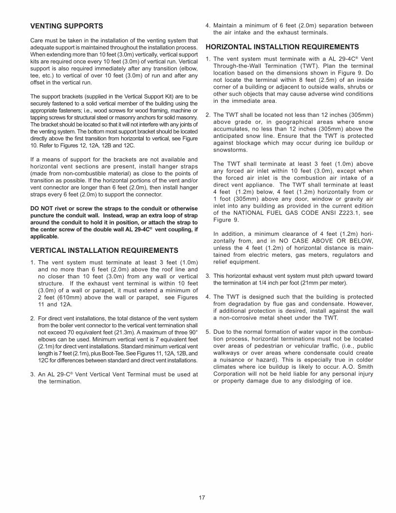
Figure 13 shows a typical primary, secondary piping method. This is the preferred piping method for most copper fin tube boilers. Other piping methods, however, may provide good system operation. A prime concern when designing heating systems is the maintenance of proper flow through the unit during boiler operation. The secondary pump should be sized per the recommended flow rate of the boiler, see Dimension and Capacity Data in this manual.
A system bypass should be installed, as shown in Figure 13, to prevent boiler circulation starvation when the system zones call for reduced flow.
This bypass may also be used with multiple boilers manifolded for reverse-return flow. This system bypass would be installed from boiler outlet to suction side of pump.
HOT WATER HEATING (HYDRONIC) EQUIPMENT
The following is a brief description of the equipment required for the installations noted in this manual. All installations must comply with local code.
1. WATER SUPPLY LINE These boilers can be used ONLY in a forced circulation
hot water heating system. Since most forced circulation systems will be of the closed type, install the water supply line as shown on piping diagram, see Figure 13.
Fast filling of large pipe, old radiator installations and pressure purging of series loop systems (where highpressures are not available) requires bypassing of thepressure reducing valve.
Gener ally, pressure purging is not possible with a well pump system. High point air venting is essential.
If the system is of the open type, a pressure reducing valve will not be required as the water supply to the system will be controlled by a manu ally operated valve. An overhead surge tank is required. A minimum pressure of 15 psi (100kPa) must be maintained on the boiler atall times to ensure avoidance of potential damage to the boiler which may not be covered by the warranty.
2. EXPANSION TANK If the system is of the closed type, install an expansion
tank as shown in Figure 13. The sizing of the expansion tank for a closed system is very important and is directly
related to the total water volume of the system. Refer to “Systems and Equipment” volume of the ASHRAEhandbook.
An air separator as shown in the piping diagrams is recom-mended especially for modern commercial hydronic systems.
3. VENT VALVES It is recommended that automatic, loose key or screw-
driver type vent valves be installed at each convector or radiator.
4. SYSTEM HEADERS Split systems with individual supply and return lines from
the boiler room should normally have this piping connected to supply and return manifold headers near the boiler. To achieve good water distribution with maximum pressure drop for sever al circuits, manifolds should be larger than system mains.
The circuits should be spaced on the heater at a minimum of3” (76mm)center tocenter. Installabalancingcock ineach return line.
Manifold headers are recommended for split systems with or without zone valves and also those installations with zone circulators. If the system is to be split at remote points, good practice requires special attention be given to main pipe sizing to allow balancing of water flow.
5. COOLING PIPING When the boiler is used in conjunction with a refrigeration
system it must be installed so that the chilled medium is piped in parallel with the boiler. Appropriate flow control valves, manual or motorized, must be provided to prevent the chilled medium from entering the boiler.
Water temperature in the heating system must be reduced tolessthan100°F(38°C)beforecoolingsystemisstarted,or damage to the chiller unit may occur.
If the boiler is connected to chilled water piping or its heating coils are exposed to refrigerated air, the boiler piping system must be equipped with flow valves or other automatic means to prevent gravity circulation through the boiler during the cooling cycle.
Primary/secondary pumping of both the chiller(s) andthe boiler(s) is an excellent winter-summer change-overmethod, because cooling flow rates are so much more thanheating flowrates. In thiswayeachsystem(heatingor cooling) is circulated independently.
6. CIRCULATING PUMP FOR HOT WATER HEATING BOILERS - VB MODELS, the
circulatingpumpisNOTprovidedandmustbefield-installed.
NOTE: If a system pump is to be installed on a VB model, the maximum rating of the pump motor must not exceed 1 hp.

23
7. SYSTEM CONTROLLER Controlling of these systems is decided mainly by the type of building system controlling desired. A single boiler installation might be controlled directly from space temperaturethermostat(s).Multipleboilerinstallationsare more effective when the boilers are sequenced in and out of operation by some form of main water temperature controller. With one or two boilers, individual control settings at progressive temperature may be used. For more than two boi lers, e lectronic sequencing control l ing is recommended. Individual controls, or the separate stages of a step controller, should start the boiler loop circulator and fire the boiler. Some large installations may require the firing of more than one boiler per stage.
The system or primary circulator may or may not be controlled by the boiler sequencer. When this pump is operated through the first switch of any type of step controller, care should be taken to determine if a motor starter is needed due to insufficient switch capacity.
Multiple boiler installations are especially adapted to the use of outdoor reset for main water temperatures. This feature is not mandatory, but offers smooth, efficient operation of a modern system.
Normal use of flow control valves is required to prevent cross circulation of zones as with any multiple pump system.
Large systems with multiple boilers should include main water temperature controls (with or without outdoor reset) to sequence the boiler on and off, in relation to the load on the system.
24VAC System Controller (Optional) - VB models require a field supplied 24VAC operating control to be installed in the system such as: loop thermostat, indoor/outdoor reset control, sequencing panel, or energy management system. The connection for such devices is located in the junction box at the rear of the unit. A 24VAC thermostat/aquastat can onlybeusedasan “On/Off”switch for theunit.Theactualcontrolling of the phasing will be through either the inlet or remote probe. To use a 24VAC system controller, dipswitch “4”on theMCBmustbeswitched to the “on”position,seeREMOTE PROBE INSTALLATION.
INTERNAL CONTAMINANTSThe hydronic system must be internally cleaned and flushed after a new or replacement boiler has been installed, to remove contaminants that may have accumulated during installation. This is extremely important when a replacement boiler is installed into an existing system where Stop Leak or other boiler additives have been used.
Failure to clean and flush the system can produce acid concentrations that become corrosive, and leads to heat exchanger failure.
All hot water heating systems should be completely flushed with a grease removing solution to assure trouble-free opera-tion. Pipe joint compounds, soldering paste, grease on tubing and pipe all tend to contaminate a system
Failure to flush contaminants from a system can cause solids to form on the inside of boiler exchangers, create excessive blockage of water circulation, deterioration of the pumps seal and impellers.
HOT WATER SUPPLY BOILER SYSTEM - GENERAL WATER LINE CONNECTIONS
This section provides detailed installation diagrams for a typical method of application for the unit.
Piping diagrams will serve to provide the installer with a reference for the mater ials and methods of piping necessary for installation. It is essential that all water p ip ing be insta l led and connected as shown on the diagrams. Check the diagrams to be used thoroughly before star ting installation to avoid possible errors and to minimize time and material cost.
I t is essent ia l that a l l water p ip ing be instal led and connected as shown on the diagrams. Check the diagrams to be used thoroughly before star ting installation to avoid possible errors and to minimize the time and material cost.
HARD WATER CONDITIONS
Where hard water conditions exist, water sof tening or the threshold type of water treatment is recommended. This will protect the dishwashers, cof fee urns, water heaters, water piping and other equipment. When water sof tening or water treatment is not practical, a comparatively easy method of periodic lime removal from the unit may be employed.
SHUTOFF VALVES SHOULD BE INSTALLED FOR SERVICING BOILER, HOWEVER, LOCAL CODES SHALL GOVERN THEIR USAGE.
THERMAL EXPANSION (CLOSED SYSTEM)
As water is heated, it expands (thermal expansion). Ina closed system the volume of water will grow when it is heated. As the volume of water grows there will be a corresponding increase in water pressure due to thermal expansion. Thermal expansion can cause premature tank failure (leakage). This type of failure is not covered underthe limited warranty. Thermal expansion can also cause intermittent Temperature-Pressure Relief Valve operation: water discharged from the valve due to excessive pressure build up. This condition is not covered under the limited warranty. The Temperature-Pressure Relief Valve is not intended for the constant relief of thermal expansion.
A properly sized thermal expansion tank must be installed on all closed systems to control the harmful effects of thermal expansion. Contact a local plumbing service agency to have a thermal expansion tank installed.
REMOTE PROBE INSTALLATION PROCEDURE
A remote probe is supplied with each hot water supply boiler (VWmodels). To connect the remote probe to theboiler, remove the cover from the junction box at the rear of the unit. Connect the probe wire pigtails, see Figure 7. Check the f ield connection diagram located on this cover of the junction box to assure proper wiring.
Once the remote probe has been connected to the boiler, it must be designated as the controlling probe for the system.

24
This is accomplished by changing two dipswitch settings on the MCB.First,dipswitch “4”mustbeset to the “ON”position todesignate the remote probe as the controlling probe. Second, dipswitch “1” must be set to the “OFF” position to limit themaximum remote probe temperature for VW applications. Also, makesuredipswitch“1”issettothe“OFF”position,whichsetsthe outlet temperature for VW applications. Failure to do this will void the warranty. If the remote probe is not designated as the controlling probe, the unit will be controlled by the inlet probe and will not use the desired tank temperature as its base.
Refer to Connection Diagram, Figure 17, in order to connect the remote probe to the boiler, see Tables 9, 10, 13 and 14 for Dipswitch positions.
GAS CONNECTIONS
Make sure the gas on which the boiler is to operate is the same as that specified on the rating plate. Do not install the boiler if equipped for a different type of gas. Consult your gas supplier.
This boiler is not intended to operate at gas supply pressure other than shown on the rating plate. A lock-up or positive shut-off type regulator must be installed in the gas supply line. Exposure to higher gas supply pressure may cause damage to gas valves which can result in fire or explosion. If overpressure has occurred such as through improper testing of gas lines or emergency malfunction of the supply system, the gas valves must be checked for safe operation. Make sure that the outside vents on the supply regulators and the safety vent valves are protected against blockage. These are parts of the gas supply system, not the boiler. Vent blockage may occur during ice build-up or snowstorms.
The boiler must be isolated from the gas supply piping system by closing its main manual gas shut-off valve during any pressure testing of the gas supply piping system at test pressures equal to or less than 1/2 psig.
Disconnect the boiler and its main manual gas shut-off valve from the gas supply piping during any pressure testing of the gas supply system over 1/2 psig. The gas supply line must be capped when not connected to the boiler.
It is important to guard against gas valve fouling from contaminants in the gas ways. Such fouling may cause improper operation, fire or explosion. If copper supply lines are used they must be approved for gas service.
When local codes require a main manual shut-off valve outside the boiler jacket, a suitable main manual shut-off valve must be installed in a location complying with those codes.
Before attaching the gas line be sure that all gas pipe is clean on the inside.
To trap any dirt or foreign material in the gas supply line, a dripleg(sedimenttrap)mustbeincorporatedinthepiping.Thedrip leg must be readily accessible and not subject to freezing conditions. Install in accordance with recommendations of serving gas supplier. Refer to the current edition of the national fuel gas code, ANSI Z223.1 or CAN/CSA – B149.1, and current addenda.
Size of gas supply piping may be larger than heater connection on installationswhereasignificantrunofpipingisrequired.
To prevent damage, care must be taken not to apply too much torque when attaching gas supply pipe to boiler gas inlet.
Fittings and unions in the gas line must be of the metal to metal type.
Applyjointcompounds(pipedope)sparinglyandonlytothemalethreadsofpipejoints.Donotapplycompoundtothefirsttwothreads.Usecompoundsresistanttotheactionofliquefiedpetroleumgases.
GAS SUPPLY LINE SIzINGThe gas piping installation must be capable of supplying the maximum probable gas demand without excessive pressure loss. Depending on local practices, the ALLOWABLE PRESSURE LOSS between the gas meter, or service regulator and each applianceisgenerally0.3or0.5inchesofwatercolumn(0.075or0.124kPa).
For single boiler installation, refer to Table 5 for appropriate pipe length for the appliance maximum rate.
For multiple boilers refer to Table 6 for natural gas and Table 7 for propane. Maximum pressure drop is 0.5 for these charts.
Reference tables are from ANSI Z223.1 National Fuel Gas Code or CAN/CSA-B149.1-00(andcurrentaddenda):
Natural gas is 1000 BTU/ft^[email protected]
Propane gas is 2500 BTU/ft^[email protected]
< pipe length longer than 200 feet consult applicable codes
No additional allowance is necessary for an ordinary number of fittings.Whereitisnecessarytousemorethantheaveragenumberoffittings(i.e.,elbows,teesandvalvesingassupplyline)useapipelargerthanspecifiedtocompensateforincreasedpressuredrop.
TABLE 5.SINGLE UNIT INSTALLATION, SUGGESTED GAS PIPE SIzING.
MAXIMUM EQUIVALENT PIPE LENGTH (IN FEET).
Nom. Pipe0.3 in w.c. drop
1” 1.25” 1.5” 2”BTU input Nat Prop Nat Prop Nat Prop Nat Prop500,000 10 25 40 90 80 200 200750,000 10 10 40 40 90 125 <
1,000,000 10 20 20 50 70 175
Nom. Pipe0.5 in w.c. drop
1” 1.25” 1.5” 2”BTU input Nat Prop Nat Prop Nat Prop Nat Prop500,000 10 40 60 150 150 200 <750,000 10 30 70 70 150 200
1,000,000 10 10 40 30 90 125 <

25
FIG
UR
E 13
. TY
PIC
AL
PRIM
ARY
, SEC
ON
DA
RY P
IPIN
G.
•INSTA
LLIN
ACCORDANCEW
ITHALLLOCALCODES.
•WHENBLO
WDOWNVALVEISREQUIRED,INSTA
LL
IN
PLA
CE
OF
THE
DR
AIN
VA
LVE
SH
OW
N.
DA
NG
ERTE
MPE
RAT
UR
E SE
TTIN
G S
HO
ULD
NO
T EX
CEE
D
SAFE
USE
TEM
PER
ATU
RE
AT F
IXTU
RES
. I
F H
IGH
ER
PR
EH
EA
T TE
MP
ER
ATU
RE
S A
RE
NEC
ESSA
RY T
O O
BTA
IN A
DEQ
UAT
E B
OO
STER
O
UTP
UT,
AD
D A
N A
NTI
-SC
ALD
VA
LVE
FOR
HO
T W
ATER
SU
PPLI
ED T
O F
IXTU
RES
, SEE
TA
BLE
8..
TYPI
CA
L PR
IMA
RY, S
ECO
ND
ARY
PIP
ING
.
26
DA
NG
ERTE
MPE
RAT
UR
E SE
TTIN
G S
HO
ULD
NO
T EX
CEE
D S
AFE
U
SE T
EMPE
RAT
UR
E AT
FIX
TUR
ES. I
F H
IGH
ER P
REH
EAT
TEM
PER
ATU
RES
AR
E N
ECES
SARY
TO
OB
TAIN
AD
EQU
ATE
BO
OST
ER O
UTP
UT,
AD
D A
N A
NTI
-SC
ALD
VA
LVE
FOR
HO
T W
ATER
SU
PPLI
ED T
O F
IXTU
RES
, SEE
TA
BLE
8.
ON
E VF
(MO
DEL
VW
) HO
T W
ATER
SU
PPLY
BO
ILER
WIT
H V
ERTI
CA
L TA
NK
FIG
UR
E 14
.
•INSTA
LLIN
ACCORDANCEW
ITHALLLOCALCODES.
•WHENBLO
WDOWNVALVEISREQUIRED,INSTA
LL
IN
PLA
CE
OF
THE
DR
AIN
VA
LVE
SH
OW
N.

27
ON
E VF
(MO
DEL
VW
) HO
T W
ATER
SU
PPLY
BO
ILER
WIT
H H
OR
IzO
NTA
L TA
NK
DA
NG
ERTE
MPE
RAT
UR
E SE
TTIN
G
SHO
ULD
NO
T EX
CEED
SAF
E US
E TE
MPE
RATU
RE
AT F
IXTU
RES
. IF
HIG
HER
PR
EHEA
T TE
MPE
RAT
UR
ES
AR
E N
ECES
SAR
Y TO
O
BTA
IN
AD
EQU
ATE
BO
OST
ER
OU
TPU
T, A
DD
AN
AN
TI-S
CA
LD V
ALV
E FO
R
HO
T W
ATE
R
SU
PP
LIE
D
TO
FIXT
UR
ES, S
EE T
AB
LE 8
.
FIG
UR
E 15
.
•INSTA
LLIN
ACCORDANCEW
ITHALLLOCALCODES.
•WHENBLO
WDOWNVALVEISREQUIRED,INSTA
LL
IN
PLA
CE
OF
THE
DR
AIN
VA
LVE
SH
OW
N.

28
WIRING
Label all wires prior to disconnection when servicing controls. Wiring errors can cause improper and dangerous operation.Verify proper operation after servicing. Strict adherence to the wiring diagrams is required to prevent constant pump operation whenthesystemcontrollerissatisfied.Otherwisethewarrantyisvoid as stipulated in the limited warranty in this installation manual.If any of the original wire, as supplied with the appliance, must be replaced, it must be replaced with type 105°C wire or its equivalent.
Figure 16.
There are five (5) electrical connections thatmust bemadefor the unit to operate correctly:
1. BLACK (No Stripe) 120VHOT
2. WHITE 120V NEUTRAL
3. GREEN GROUND
4. (2)TANKPROBEOR(2)ENABLE/DISABLE***
*** Enable/disable can also be used with a 24 volt thermostat. Do not use tank probe when using thermostat.
These connec t ions sha l l be made a t the rea r o f t he un i t where a j unc t i on box i s p rov ided . AN ELECTRICAL GROUND IS REQUIRED TO REDUCE THE RISK OF ELECTRIC SHOCK OR POSSIBLE ELECTROCUTION. A GROUND SCREW IS PROVIDED IN THIS JUNCTION BOX.
NOTE: Tank probes are not provided on VB models, it is required that a system/operating temperature controller (field supplied) be installed to regulate loop or system temperatures. Two yellow wires are provided in the rear junction box for this connection. Do not operate this boi ler without system or operating control.
When operating the boiler with the tank probe the enable/disable must be wired together.
Refer to the Connection Diagram, see Figure 17, and to the Schematic Diagram, see Figure 18.

29
SUGGESTED PIPE SIzING TABLES
TAB
LE 7
. Su
gges
ted
Pipe
Siz
e Fo
r Mul
tiple
Gas
App
lianc
es (P
ropa
ne G
as).
Nom
inal
Maximum
CapacityofP
ipeinBTU
/hrandkWforG
asPressuresof14in.W
.C.(0.5psi)orLessand
IronPipe
aPressureDropof0.5in.W
.C.(basedon0.60SpecificGravityGasw/HeatingValueof1,000BTU
’s/Ft3)
Size
LengthofP
ipeinFeet(Meters)
(Inches)
10(3.05)
20(6.1)
30(9.14)40(12.19)50(15.24)60(18.29)70(21.34)80(24.38)90(27.43)100(30.48)125(38.1)
150
175
200
1
BTU
/hr
1,06
0,80
0 72
5,40
0 58
5,00
0 49
9,20
0 —
—
—
—
—
—
—
—
—
—
kW
31
1 21
2 17
1 14
6 —
—
—
—
—
—
—
—
—
—
1 1/
4 B
TU/h
r 2,
184,
000
1,48
2,00
0 1,
201,
200
1,02
9,60
0 90
4,80
0 82
6,80
0 76
4,40
0 71
7,60
0 67
0,80
0 62
4,00
0 56
1,60
0 50
7,00
0 46
8,00
0 —
kW
640
434
352
302
265
242
224
210
196
183
164
148
137
—
1 1/
2 B
TU/h
r 3,
276,
000
2,27
7,60
0 1,
840,
800
1,54
4,40
0 1,
404,
000
1,26
3,60
0 1,
170,
000
1,07
6,40
0 1,
014,
000
967,
200
858,
000
780,
000
717,
600
670,
800
kW
959
667
539
452
411
370
343
315
297
283
251
228
210
196
2
BTU
/hr
6,16
2,00
0 4,
290,
000
3,43
2,00
0 2,
964,
000
2,62
0,80
0 2,
371,
200
2,18
4,00
0 2,
028,
000
1,90
3,20
0 1,
794,
000
1,59
1,20
0 1,
482,
000
1,32
6,00
0 1,
248,
000
kW
1,80
5 1,
256
1,00
5 86
8 76
8 69
4 64
0 59
4 55
7 52
5 46
6 43
4 38
8 36
6
2 1/
2 B
TU/h
r 9,
828,
000
6,78
6,00
0 5,
491,
200
4,68
0,00
0 4,
134,
000
3,74
4,00
0 3,
510,
000
3,19
8,00
0 3,
042,
000
2,88
6,00
0 2,
574,
000
2,34
0,00
0 2,
137,
200
1,99
9,80
0
kW
2,
878
1,98
7 1,
608
1,37
1 1,
211
1,09
7 1,
028
937
891
845
754
685
626
585
3
BTU
/hr
17,1
60,0
00 1
2,01
2,00
0 9,
750,
000
8,26
8,00
0 7,
410,
000
6,70
8,00
0 6,
084,
000
5,77
2,00
0 5,
382,
000
5,07
0,00
0 4,
602,
000
4,13
4,00
0 3,
822,
000
3,55
6,80
0
kW
5,
026
3,51
8 2,
856
2,42
1 2,
170
1,96
5 1,
782
1,69
0 1,
576
1,48
5 1,
348
1,21
1 1,
119
1,04
2
4
B
TU/h
r 35
,880
,000
24,
648,
000
19,9
68,0
00 1
7,00
4,00
0 15
,132
,000
13,7
28,0
00 12
,636
,000
11,7
00,0
00 11
,232
,000
10,4
52,0
00 9
,360
,000
8,5
80,0
00 7
,800
,000
7,1
76,0
00
kW
10,5
08
7,21
9 5,
848
4,98
0 4,
432
4,02
1 3,
701
3,42
7 3,
290
3,06
1 2,
741
2,51
3 2,
284
2,10
2 TA
BLE
6.
Sugg
este
d Pi
pe S
ize
For M
ultip
le G
as A
pplia
nces
(Nat
ural
Gas
).Nom
inal
Maximum
CapacityofP
ipeinBTU
/hrandkWforG
asPressuresof14in.W
.C.(0.5psi)orLessand
IronPipe
aPressureDropof0.5in.W
.C.(basedon0.60SpecificGravityGasw/HeatingValueof1,000BTU
’s/Ft3)
Size
LengthofP
ipeinFeet(Meters)
(Inches)
10(3.05)
20(6.1)
30(9.14)40(12.19)50(15.24)60(18.29)70(21.34)80(24.38)90(27.43)100(30.48)125(38.1)
150
175
200
1
BTU
/hr
680,
000
465,
000
—
—
—
—
—
—
—
—
—
—
—
—
kW
199
136
—
—
—
—
—
—
—
—
—
—
—
—
1
1/4
BTU
/hr
1,40
0,00
0 95
0,00
0 77
0,00
0 66
0,00
0 58
0,00
0 53
0,00
0 49
0,00
0 46
0,00
0 —
—
—
—
—
—
kW
41
0 27
8 22
6 19
3 17
0 15
5 14
4 13
5 —
—
—
—
—
—
1 1/
2 B
TU/h
r 2,
100,
000
1,46
0,00
0 1,
180,
000
990,
000
900,
000
810,
000
750,
000
690,
000
650,
000
620,
000
550,
000
500,
000
460,
000
—
kW
615
428
346
290
264
237
220
202
190
182
161
146
135
—
2
BTU
/hr
3,95
0,00
0 2,
750,
000
2,20
0,00
0 1,
900,
000
1,68
0,00
0 1,
520,
000
1,40
0,00
0 1,
300,
000
1,22
0,00
0 1,
150,
000
1,02
0,00
0 95
0,00
0 85
0,00
0 80
0,00
0
kW
1,
157
805
644
556
492
445
410
381
357
337
299
278
249
234
2
1/2
BTU
/hr
6,30
0,00
0 4,
350,
000
3,52
0,00
0 3,
000,
000
2,65
0,00
0 2,
400,
000
2,25
0,00
0 2,
050,
000
1,95
0,00
0 1,
850,
000
1,65
0,00
0 1,
500,
000
1,37
0,00
0 1,
280,
000
kW
1,84
5 1,
274
1,03
1 87
9 77
6 70
3 65
9 60
0 57
1 54
2 48
3 43
9 40
1 37
5
3
B
TU/h
r 11
,000
,000
7,7
00,0
00
6,25
0,00
0 5,
300,
000
4,75
0,00
0 4,
300,
000
3,90
0,00
0 3,
700,
000
3,45
0,00
0 3,
250,
000
2,95
0,00
0 2,
650,
000
2,45
0,00
0 2,
280,
000
kW
3,22
2 2,
255
1,83
0 1,
552
1,39
1 1,
259
1,14
2 1,
084
1,01
0 95
2 86
4 77
6 71
8 66
8
4
B
TU/h
r 23
,000
,000
15,
800,
000
12,8
00,0
00 1
0,90
0,00
0 9,
700,
000
8,80
0,00
0 8,
100,
000
7,50
0,00
0 7,
200,
000
6,70
0,00
0 6,
000,
000
5,50
0,00
0 5,
000,
000
4,60
0,00
0
kW
6,
736
4,62
7 3,
749
3,19
2 2,
841
2,57
7 2,
372
2,19
7 2,
109
1,96
2 1,
757
1,61
1 1,
464
1,34
7

30
WIRING DIAGRAMFI
GU
RE
17.
CO
NN
ECTI
ON
DIA
GR
AM

31
WIRING DIAGRAM

32
FIGURE 18. - SCHEMATIC DIAGRAM
VB/VW-500, 750 & 1000 SCHEMATIC DIAGRAM

33
OPERATION
IMPORTANTOnlyqualifiedpersonnelshallperformtheinitialfiringoftheboiler.At this time the user should not hesitate to ask the service agent any questions regarding the operation and maintenance of the unit. If you still have questions, please contact the factory or your local A.O. Smith representative.
Lighting and Operating instructions are included with this manual. By using these instructions, the user may be able to make minor operational adjustments and save unnecessary service calls. However the user should not attempt repairs, but should contact a service technician or gas supplier.
GENERALNeveroperatetheboilerwithoutfirstmakingsuretheboilerandsystemarefilledwithwater,inaddition:
For hot water supply installations:
• Makesureatemperatureandpressurereliefvalveisinstalledatthe boiler and, if used, the storage tank. Also check for leaks.
For heating boiler installations:
• Makesurethattheboilerandsystemhavebeenpurgedofairand checked for leaks.
Also be sure to check the gas piping for leaks before beginning the initialfiringoftheboiler.
FILLING AND PURGING OF HEATING BOILER INSTALLATION1. Fast fill system through bypass until pressure approaches
desired system pressure. Close bypass valve and permit pressure to be established by the pressure reducing valve.
2. Vent all high points in system to purge system of air.
Provisions should be made to permit manual venting of radiators or convectors.
F ILL ING HOT WATER SUPPLY BOILER INSTALLATION
1. Close the system’s drain valve by turning handle clockwise.2. Open a nearby hot water faucet to permit the air to escape.3. Fully open the cold water inlet pipe valve allowing the boiler
andpipingtobefilled.4. Closethehotwaterfaucetaswaterstartstoflow.5. The boiler is ready to be operated.
PURGING GAS LINEGas line purging is required with new piping or systems in which air has entered.
INLET GAS PRESSURETheinletgaspressureismeasuredbyremovingthe1/8”NPTPluglocated on the main gas manifold which is upstream of the unit’s gas valve,andinserta1/8”NPThosebarbfittingtobeconnectedtoamanometer or pressure gauge. Once pressure has been checked and/or adjusted, replace the plug and check for leaks. The maximum value specifiedinthetablemustnotbeexceeded.Theminimumvalues,shown in Table 1, must be maintained under both load and no load conditions(staticandfiringconditions).Thecombinationgasvalvessupplied with the boiler are for low pressure service. If upstream pressure exceeds 14.0” W.C., an intermediate gas pressure regulator of the lockup type must be installed.
FIGURE 19. GAS TRAIN ASSEMBLY.

34
The boiler should be located in an area that is inaccessible to the general public.Never allow small children to use a hot water tap or to draw their own bath water. Never leave a child or handicapped person unat-tended in a bathtub or shower.
TABLE 8. Risk of Scalds.
Water Temperature TimetoProduce2nd&3rdDegreeBurns on Adult Skin
Over170°F(77°C) Nearly instantaneous
160°F(71°C) About 1/2 second
150°F(66°C) About 1-1/2 seconds
140°F(60°C) Less than 5 seconds
130°F(54°C) About 30 seconds
120°F(49°C)orless More than 5 minutes
SHOULD OVERHEATING OCCUR OR THE GAS SUPPLY FAIL TO SHUT OFF, TURN OFF THE MAIN MANUAL GAS SHUTOFF VALVE TO THE APPLIANCE.
The operating temperature of the boiler must be maintained as follows:
• 120°F(49°C)orhigherinletwatertemperaturetotheboiler.
• 20°F(11°C)differentialbetweentheboiler’sinletandoutlet(e.g.120°F[49°C]inlet,140°F[60°C]outletminimumdesigntemperatures).
Iftheinletwatertemperatureintotheboilerislessthan120°F(49°C),adjustments on the water bypass and the outlet valves at the rear of the boiler, see Figures 14 and 15, are required; wait at least one minute between adjustments for the temperature to stabilize.
1) Ifnecessary,throttledown(close)thewateroutletgate/ballvalveuntilthedesiredoutletwatertemperature(120°F[49°C]minimum)isreached.Waitoneminute.
2) Notetheoutletandinlettemperatureindicatorreadings.
a) If the inletwater temperature is less than120°F(49°C),open, insmall increments, thebypass(balancing)valveuntil theminimum120°F (49°C) inletwater temperatureor20°F(11°C)differential,whicheverhasthehigherinlettemperature, is attained.
b) Iftheinletwatertemperatureisgreaterthan120°F(49°C)andthe20°F(11°C)differential isnotpresent,closethebypassvalveuntilthe20°F(11°C)differentialisattained.
NOTE: It may be necessary to make further adjustments on the outlet and bypass valves until the desired inlet and outlet water temperatures are reached.
MANIFOLD PRESSURE CONNECTIONS
Take the manifold pressure, refer to Table 1, by removing the pipeplugand insertinga suitable 1/8”NPThosebarb forconnection to the manometer/pressure gauge. Upon completion of measurements and adjustments, remove the hose barb and replace the pipe plug. Check for gas leaks and insure all connections are gas tight, see Figure 19..
WATER TEMPERATURE REGULATION
HOT WATER CAN SCALD: Boilers are intended to produce hot water. Water heated to a temperature which will satisfy space heating, clothes washing, dish washing and other sanitizing needs can scald and permanently injure you upon contact. Some people are more likely to be permanently injured by hot water than oth-ers.Theseincludetheelderly,children,theinfirmorphysically/mentallydisabled. Ifanyoneusinghotwater inyourhomefitsinto one of theses groups or if there is a local code or state law requiringaspecifictemperaturewateratthehotwatertap,thenyou must take special precautions. In addition to using the lowest possibletemperaturesettingthatsatisfiesyourhotwaterneeds,a means such as a mixing valve should be used at the hot water taps used by these people or at the hot water supply tank. Mixing valves are available at plumbing supply or hardware stores. Fol-low the manufacturer’s instructions for installation of the valves. Before changing the thermostat setting on the hot water system controller, see Table 8.
Hot water temperatures required for automatic dishwasher and laundry use can cause scald burns resulting in serious personal injury and/or death. The temperature at which injury occurs varies with the person’s age and time of exposure. The slower response time of children, aged or disabled persons increases the hazards to them. Never allow small children to use a hot water tap, or to draw their own bath water. Never leave a child or disabled person unattended in a bathtub or shower.

35
MCB - Ten Position Dipswitch:DipswitchconfigurationsareREAD ONLY ON POWER UP. These switches are only to be set at the factory or by authorized trained personnel! Once set the boiler will operate according to the chosen options. If a switch is changed, power must be cycled before the change will take effect. The status of all dipswitches can be observed on the system status screen on the UIM.
TABLE 9. - MCB/FCB Dipswitches:
Dipswitch Function Switch Position Hot Water Boilers Hydronic Heating Boiler Switch 1: Selection of the type of boiler application: On = VB Off = VW Switch 2: Trials for ignition: On = 3 Off = 1 Switch 3: IRI Gas Valve Not Available: Switch4:ControllingProbe: On=Tank(Remote) Off=Inlet Switch 5: Powered Venter: On = Yes Off = No Switch6:LowWaterCutOff:(LWCO) On=Yes Off=No Switch 7: Low Gas Pressure On = Yes Off = No Switch 8: Modulation: On
NOTE: If the unit powers up with the number of stages selected by dip switches exceeding the number of FCBs, the MCB will detect this condition and go into a hard lockout. After changing the dipswitches, the power must be cycled off and back on to accept any changes.
ExampleofDipswitchconfiguration: VB model, 1ignition trial, not used, tank / remote probe, no power vent, No LWCO, no low gas pressure, modulation, not used, not used.
MCB - Three position Dipswitch:This dipswitch is similar to the MCB dipswitches described above, but with only three switches being used: the number of blower speeds (switch#3),HiGasoption(switch#2)andaspare(switch#1).OnlytheblowerspeedandHiGasoptionsaretherequiredselection,within the MCB, see Figure 17.
TABLE 10.
Dipswitch Function: Dipswitch Position Switch 1: Spare: Switch 2: Hi Gas pressure switch: On = Yes Off = No Switch 3: Number of Blower Speeds: On = 1 speed, Off = 2 speed
ExampleofDipswitchconfiguration: No High Gas, 1 blower speed.

36
LIGHTING & OPERATION INSTRUCTIONS FOR MODELS VB/VW 500, 750 AND 1000:
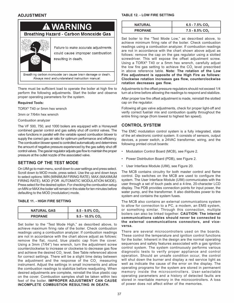
37
ADJUSTMENT
Theremustbesufficientloadtooperatetheboilerathighfiretoperform the following adjustments. Start the boiler and observe proper operating parameters for the system.
Required Tools:TORX® T40 or 5mm hex wrench
3mm or 7/64in hex wrench
Combustion analyzer
The VF 500, 750, and 1000 boilers are equipped with a Honeywell combined gas/air control and gas safety shut off control valves. The valve functions in parallel with the variable speed combustion blower to supplythecorrectgasairratioforoptimumperformanceandefficiency.The combustion blower speed is controlled automatically and determines the amount of negative pressure experienced by the gas safety shut off/controlvalves.Thegas/airregulatoradjustsgasflowtomaintaintheproperpressure at the outlet nozzle of the associated valve.
SETTING OF THE TEST MODEOn UIM go to main menu, scroll down to user settings and press select. Scroll down to MOD mode, press select. Use the up and down keys toselectoptions:MIN(MINIMUMFIRINGRATE).MAX(MAXIMUMFIRINGRATE).MOD(FORAUTOMATICMODULATIONMODE).Press select for the desired option. For checking the combustion setup on MIN or MAX the boiler will remain in this state for ten minutes before defaultingtotheMOD(modulation)mode.
TABLE 11. - HIGH FIRE SETTING
NATURAL GAS 8.5 - 9.0% CO2
PROPANE 9.5 - 10.5% CO2
Set boiler to the “Test Mode High,” as described above, toachieve maximum firing rate of the boiler. Check combustion readings using a combustion analyzer. If combustion readings are not in accordance with the chart above adjust as follows: remove the flat, round, blue plastic cap from the cover. Usinga3mm(7/64”)hexwrench, turn theadjustmentscrewcounterclockwise to increase or clockwise to decrease gas flow and achieve the desired CO2 level. See Table referenced above for correct settings. There will be a slight time delay between the adjustment and the response of the CO2 measuring instrument. Adjust the settings in small increments and allow the combustion readings to stabilize before readjusting. When desired adjustments are complete, reinstall the blue plastic cap on the cover. Combustion samples shall be taken within two feet of the boiler. IMPROPER ADJUSTMENT CAN CAUSE INCOMPLETE COMBUSTION RESULTING IN DEATH.
TABLE 12. - LOW FIRE SETTING
NATURAL 6.5 - 7.5% CO2
PROPANE 7.5 - 8.5% CO2
Set boiler to the “Test Mode Low,” as described above, toachieve minimum firing rate of the boiler. Check combustion readings using a combustion analyzer. If combustion readings are not in accordance with the chart shown above adjust as follows: remove the cap on the gas regulator using a slotted screwdriver. This will expose the offset adjustment screw. Using a TORX® T40 or a 5mm hex wrench, carefully adjust the low fire gas setting to achieve the CO2 level prescribed in above reference table. Note: The rotation of the Low Fire adjustment is opposite of the High Fire as follows: Clockwise rotation increases gas flow, counterclockwise rotation decreases gas flow.Adjustments to the offset pressure regulators should not exceed 1/4 turn at a time before allowing the readings to respond and stabilize.
Afterproperlowfireoffsetadjustmentismade,reinstalltheslottedcap on the regulator.
Following all gas valve adjustments, check for proper light-off and verify correct fuel/air mix and combustion quality throughout the entirefiringrange(fromlowesttohighestfanspeed).
CONTROL SYSTEMThe EMC modulation control system is a fully integrated, state of the art electronic control system. It consists of sensors, output devices, a power switch, a 24VAC transformer, wiring, and the following printed circuit boards:
• ModulationControlBoard(MCB),seeFigure2.
• PowerDistributionBoard(PDB),seeFigure2.
• UserInterfaceModule(UIM),seeFigure20.
TheMCB contains circuitry for bothmaster control and flamecontrol. Dip switches on the MCB are used to configure the system.TheUserInterfaceModule(UIM)communicateswiththeuser through a set of touch pads and a 4-line, 20-character LCD display. The PDB provides connection points for input power, the water pump, and the transformer. It also distributes power to the system and contains the system fuses.
The MCB also contains an external communications system to allow for connection to a PC, a modem, an EMS system, or something similar. Through this connection, multiple boilers can also be linked together. CAUTION: The internal communications cables should never be connected to the external communications connectors, and vice-versa.There are several microcontrollers used on the boards. These control the temperature and ignition control functions for the boiler. Inherent in the design are the normal operating sequences and safety features associated with a gas ignition control system. The system continuously performs various diagnostic tests to verify proper appliance and control operation. Should an unsafe condition occur, the control will shut down the burner and display a red service light as well as indicate the cause of the error on the display. The operating programs for the system are stored in permanent memory inside the microcontrol lers. User-selectable operating parameters and a history of detected faults are stored in rewritable memory in the microcontrollers. A loss of power does not affect either of the memories.

38
INPUTS TO MCBTEMPERATURE SENSORS:Temperature probes (MCB-outletandeither inletor tankare required): TheMCB accepts analog temperature inputs from uptothreesensors(inlet,outlet,andtank).
MRHL(ManualResetHIGHLIMIT):TheMRHLisahi-limitswitchlocated inside the outlet probe. It is a normally closed switch that opens if the probe is exposed to a temperature higher than the trip point. Once tripped, the control system needs to be manually reset.
Thermostat input(MCB-optional):Thisinputissetuptoworkwithan externally connected thermostat that provides a contact closure. If this input is closed and everything else is in the proper state, a “call for heat”conditionwillbeinitiated.Theseleadsshouldbeshortedtogetherwhen a thermostat is not being used. If it is desired that the thermostat control the temperature of the boiler, the operating setpoint of the system should be set higher than the temperature that the thermostat is controlling. This will allow the thermostat to control the boiler. When the thermostat closes, a call for heat will be generated until the thermostat determines that the required temperature has been reached.
AIR PRESSURE SENSORS (OPEN CONDITION INDICATES FAULT):Blocked Inlet (MCB - required) Normally closed switch thatactivates if the air inlet is blocked 3/4 or more during operation.
Blocked Flue(MCB-required):Normallyclosedswitchthatopensifthefluebecomesblockedduringoperation.
Blower Prover(MCB-required):Normallyopenswitchthatcloseswhen the air pressure produced by the blower is above the set point.
GAS PRESSURE SENSORS (OPEN CONDITION INDICATES FAULT): Low Gas(MCB-required):Normallyopenswitchthatcloseswhenthe gas pressure rises above the trip level. This input is enabled/disabled by a dip switch on the MCB
Hi Gas(MCB-required):Normallyclosedswitchthatopensifthegas pressure exceeds a set value. This input is enabled/disabled by a dip switch on the MCB.
WATER LEVEL SENSOR (OPEN CONDITION INDICATES FAULT):Low Water Cut Off(MCB-optional):Normallyopenswitchthatcloses when water reaches preset level. This input is enabled/disabled by a dip switch on the MCB.
WATER FLOW SENSOR:Flow (MCB- required):Normallyopenswitch thatcloseswhenflowexceedsasetvalue.
FLAME SENSOR:Flame(MCB-required):Returnsasignaltothemicroprocessorifflameisdetectedontheburner. If theflamerodismissingorshorted,theflamewillnotbedetected.
OUTPUTS FROM MCBRELAY CONTACT OUTPUT: Alarm (MCB - 24VAC - optional):Provides electrical power tooperate an external alarm.This can be an audio device (i.e.,Sonalert), a visual device (lamp), or any other device thatwilloperate with the voltage and current level provided.
Pump (MCB-120VAC- requiredonsystems thatdonothaveanexternalpump):Provideselectricalpowertodirectlyoperateapump or the coil of an externally connected contactor.
Blower(MCB-120VAC-required):Variablespeedblowersutilizethe high blower output only.
Igniter(MCB-120VAC-required):Providespowertooperatethe HSI igniters.
Gas Valve(MCB-24VAC-required):Providespowertoactivatethe gas valve. The gas valve cannot be activated when the MRHL contacts are open.
Low Water Cut Off(MCB-24VAC-optional):Directlyconnectedtothe 24VAC line to provide power to operate an external LWCO device.
MCB AND PDB INDICATOR LAMPS AND FUSES
A green LED is mounted on the PDB to indicate when line voltage isapplied(thePDBalsocontainsayellowandredLED,andatest/run jumper that are used during installation to verify proper power connections).AredLEDontheMCBisusedtoindicatewhenthe24VAC input fuse has blown.
Yellow LEDs are located near the microcontrollers on the MCB. TheseLEDsare“heartbeatindicators,”andblinkapproximatelytwice per second to indicate that the microcontrollers are running.
MCB JUMPERSThe MCB has two jumpers. JP1 on the MCB is used to terminate the external communications line. It is normally left off and installed when the external cable is very long.
IGNITERSThe EMC modulation system operates with Silicon Carbide Igniters
MCB - Ten Position Dipswitch:DipswitchconfigurationsareREAD ONLY ON POWER UP. These switches are only to be set at the factory or by authorized trained personnel! Once set the boiler will operate according to the chosen options. If a switch is changed, power must be cycled before the change will take effect. The status of all dipswitches can be observed on the system status screen on the UIM.
TABLE 13. - MCB/FCB Dipswitches:
Dipswitch Function Switch Position Hot Water Boilers Hydronic Heating Boiler Switch 1: Selection of the type of boiler application: On = VW Off = VB Switch 2: Trials for ignition: On = 3 Off = 1 Switch 3: IRI Gas Valve Not Available: Switch4:ControllingProbe: On=Tank(Remote) Off=Inlet Switch 5: Powered Venter: On = Yes Off = No Switch6:LowWaterCutOff:(LWCO) On=Yes Off=No Switch 7: Low Gas Pressure On = Yes Off = No Switch 8: Modulation: On

39
NOTE: If the unit powers up with the number of stages selected by dip switches exceeding the number of FCBs, the MCB will detect this condition and go into a hard lockout. After changing the dipswitches, the power must be cycled off and back on to accept any changes.
ExampleofDipswitchconfiguration: VB model, 1ignition trial, not used, tank / remote probe, no power vent, No LWCO, no low gas pressure, modulation, not used, not used.
MCB - Three position Dipswitch:This dipswitch is similar to the MCB dipswitches described above, but with only three switches being used: the number of blower speeds (switch#3),HiGasoption(switch#2)andaspare(switch#1).OnlytheblowerspeedandHiGasoptionsaretherequiredselection,within the MCB, see Figure 17.
TABLE 14.
Dipswitch Function: Dipswitch Position Switch 1: Spare: Switch 2: Hi Gas pressure switch: On = Yes Off = No Switch 3: Number of Blower Speeds: On = 1 speed, Off = 2 speed
ExampleofDipswitchconfiguration: No High Gas, 1 blower speed..
OPERATING SEQUENCE1. The EMC modulation controller has four modes of operation:
Initialization, Standby, Running/Modulation, and Service. The internal MCB micros control these modes through a sequence ofsteps(orStates)whicharefurtherdescribedinthe“UIMOperatingProcedures”section.
2. When power is applied to the system, it enters the initialization mode and the following automatic functions are performed:
• A.O.Smithopeningscreenisdisplayed.
• Thesystemgoes throughacalibration indicatedby thegreen running LED blinking and then staying on; next the red service LED and yellow standby LEDs come on, next the service and runnings LEDs blink ON and OFF.
• Storedvaluesarerecalledfrommemory.
• Configurationdipswitchesareread.
• Pendingfaultsarerecalled
• Microsonallboardsstartrunning(indicatedbyaflashingYellowLEDneareachmicro)
• Inputsensorsareread
3. After initialization is complete (approximately 10 seconds)the system turns the green LED off and goes to the standby mode(yellow“Standby”LEDon),unlessapreviouslystoredfault has been recalled, which will send the system into the servicemodel(red“Service”LEDon).Instandbymodethedisplay shows the temperature screen and in fault mode the current error screen is displayed.
4. The system then compares the temperature read from the controllingprobe(inletortank)tothesetpointtemperature.Ifthe temperature is less than the operating setpoint minus the differential temperature and the thermostat input is closed then a call for heat is established and the system shifts to the run mode(green“Running”LEDturnson).
5. The heating sequence begins by applying power to the pump.
6. After a few seconds the blower is turned on for 30-second pre-purge period of combustion chamber.
7. The igniter is turned on.
8. After the igniter has reached a minimum of 2.8 amps, the gas valveisenergizedtoallowgasflowtoburner.
9. After an additional one second, the system checks the status of theflamethroughtheflamesensor.Iftheflameisnotverifiedwithin 4 seconds, the gas valve is immediately shut off followed by 15-second inter-purge period, then the system returns to step7,ifthe“TrialforIgnition”dipswitchissetforthree(3)tries.Ifthedipswitchissetforone(1)trial,thesystemwilldeclarean error and boiler will require resetting the control.
10. Theboilerwillremainrunninguntilthesetpointissatisfied.Oncesatisfied, theblowerwill continue for15-secondpostpurge period.
11. Oncesetpointhashavebeensatisfied,theboilerpumpwillcontinue to run for the programmed post-circulate cycle.
12. The control now enters the idle state as displayed by the “Standby” LED.The control will continue tomonitor heatdemand and state of other system devices. Upon a drop of water temperature below the set parameters, the control will return to step 5 and repeat the entire operating cycle. Note: Any fault detection, during standby or running modes, will halt the heating sequence and shift the system to the service mode where the detected fault will be displayed.
NOTE: In standby and running modes the system constantly monitors the signals and the internal operation for faults. Any detected fault will halt the heating sequence and shift the system to the service mode, where the detected fault will be displayed.
TEMPERATURE SETPOINTS (SYSTEM CONTROL ALGORITHM)The boiler has a hysteresis type control, which means that it will begin heating the water when the temperature sensed by the controlprobe(inletortank)fallsbelowtheoperatingsetpointminusthe differential setpoint. It will stop heating the water when the temperature rises to the operating setpoint.

40
UIM OPERATING PROCEDURES
FIGURE 20. UIM, USER INTERFACE MODULE
The UIM receives commands from the user and displays operational informationtotheuserviaanLCD(liquidcrystaldisplay)uptoelevenLED’s,andfivetouchswitches.TheLCDprovidesinformationtothe user by the use of 10 menu-activated screens. Within each of the screens, helpful information can be displayed by pressing the “Help”button.TheLED’svisuallyinformtheuseraboutthemodethe system is in. The touch switches allow the user to control the operation of the system. The operation of these parts is described in the following section:
UIM Screens:On all screens a double vertical bar appears on the right side of the display each time a key is touched to indicate that a key has beenactivated.Onseveralscreensanindicator“>”appearsonthe left side of the display to indicate the active line. The “Up/Down”keysareusedtomovetheindicatortothedesiredlineandthe“Select”keyispressedtoselecttheline.Also,onmostofthescreens, up/down arrows appear on the right side of the screen to indicate that there is additional lines either above or below the displayed four lines.
• Menu Screen: Displayedwhentheuserpressesthe“Menu”key.Thisscreen
is the selection point for the other 9 screens.
• Temperature Screen: Displays the sensed temperatures of the Outlet, Inlet, and
Tankprobes.AlsodisplayedisthecalculatedDeltaT(OutletminusInlet)forthesystem.Shorted(“Short”)anddisconnected (“----”)probesarealsodisplayed.
• System Status Screen: This screen is used to view the status of switch inputs and output
states.Anasterisk(*)isdisplayednexttothelabelwhenthestatus is “True” (thedescription is fulfilled). For example, ifwaterisflowing,ordetectedbytheflowsensor,thenan“*”willappearinfrontoftheFlowlabel(i.e.*Flow).Anotherexamplewould be the ECO switch. If the outlet temperature is too high the display will show: *ECO.
The System monitors the inputs of these times:
• MRHL,BlockedInlet,BlockedFlue,LowGas,HiLimit,andHiGas - at all times for a fault condition.
• Tstat-atalltimesforopen/closedconditions.
• Flow-foranonconditionwhenthepumpison(nocheckforoffstate)
• BlowerProver-whentheBlowerison.
• IgniterCurrent-foranonconditionapproximately18seconds
after the Igniter is turned on until the igniter is turned off and an off condition at all other times.
• Flame-foranonconditionapproximately5secondsafterthegas valve is turned on until the valve is turned off and at all other times for an off condition.
Control Status Screen:Displays the status that the MCB micros are in. The MCB has 5 possible states and the FCB have 9. The normal MCB states sequence is to move from Idle to Pre-Circulate when a call for heatisinitiated.OnceheathasbeensatisfiedortheThermostatis opened, the sequence moves to Post-Circulate and then back to Idle. If a fault occurs at any time, the process jumps out of sequence and goes directly to the appropriate Hard or Soft Fault state.
Description of MCB control states:• Idle:
Theyellow“Standby”LEDisturnedonandthesystemwaitsforaheatrequest(determinedbytheThermostatorcontrollingprobeinputs).AlloutputsareoffinthisstateexceptthatifthePost-Circulate time is set to continuous, the pump will be on. When the heat request is received, the system moves to the Pre-Circulate state.
• Pre-Circulate:
TheyellowLEDisturnedoffandthegreen“Running”LEDisturned on. The green LED will remain on for all other states except the fault states. Cold purging clears out any combustion gas that may be in the combustion chamber. When purging is complete the system moves to the Heat State.
• HeatStage
The system will command the FCB micros to start their heat sequence. will be activated in order based on an algorithm that determines how much heat is needed. The system will remain in thisstateuntiltheheatrequestissatisfied,theTstatisopened,or a fault occurs.
• SoftFaultState:(See“FaultDescription”sectionforlistofsoftandAutoResetfaults.)
The pump remains on for the selected post-circulate time to cycle the hot water out of the boiler. The FCB is commanded to shut down and the Alarm output is turned on. The green LED turnsoffandthered“Service”turnson.TheMCBremainsinthis state until one of the following occurs:
• Onehourpasses(automaticrestartafteronehour)
• IfCommunicationserrorsystemwillautomatically restart if communications re-establishes.
• IfuserpressesSelectkeywhilecurrenterrorscreenis displayed(Hardreset).
• Ifhigh-limiterror-theoutlettemperaturedropsbelowthehighlimittrippointminusthehighlimitdifferential.(outletwatertemperaturedropstosafelevel).Thefaultisloggedin the error history when the fault state is exited.
• HardFaultState:(See“FaultDescription”sectionforlistofsoftandAutoResetfaults.)Thepumpremainsonfortheselected post-circulate time to cycle the hot water out of the boiler. The FCB is commanded to shut down and the Alarm output is turned on. The green LED turns off and the red “Service”turnsonandoff(flashes).Theonlywaytoexitthis state is for the user to press the Select key while the current error screen is displayed. The fault is logged in the error history when the fault state is exited.
While the MCB is in the Heating mode the FCB moves from Idle, to Pre-Purge, to Heat Igniter, to Check for Flame, and then to Heating.

41
Theprocesswaitsinthisstateuntilthecallforheatissatisfied,thethermostatinputisopened,orafaultoccurs.Whenheatissatisfied,the sequence continues to Post-Purge and then back to Idle. If three tries for ignition has been selected on the MCB dipswitch and flameisnotdetectedattheappropriatetime,thenthesequencemoves to the Inter-Purge state for 15 seconds and the FCB heat sequenceisrepeated.Ifflameisstillnotdetectedafterthethirdtrythe process declares a fault, jumps out of sequence and goes to the error state. Other types of faults detected at any time will also cause a jump to the error state.
Description of FCB control states:• IdleState:
When any error is declared during idle state-The system will remain in this state until the MCB request a heating cycle, or a cold purge.
• Pre-PurgeState:
Thebloweristurnedon.After10to34seconds(34secondsforcoldpurging)thesystemswitchestotheHeatIgniterState.
• HeatIgniterState:
The sequence of operation is as follows: “The igniter relay is energized and the heat up period begins. After 18-20 seconds, if the igniter has reached a minimum of 2.8 amps, the gas valve safety circuit is then activated. If in this amount of time, the igniter fails to reach a minimum amp draw of 2.8 amps, the unit will re-cycle up to 3 times before locking out on igniter hardware failure. If the igniter does reach the minimum required amp draw of 2.8 amps, the gas valve circuit is energized, and the system advances to Flame Check status.
• CheckforFlameState:
The gas valve is turned on. After 1.5 seconds, the system checks that the gas valve relay is on. If it is not, the ignition trial is considered to have failed and the system advances to the Inter-Purge state, if any ignition trials remain, otherwise an error is declared.
Theflamesensorischecked.Ifflameisdetected,theigniteris turned off. The state machine then advances to the Heating State.Ifafter5seconds,theflameisstillnotsensedthentheignition trial is considered to have failed. The state machine advances to Inter-Purge if any ignition trials remain, otherwise an error is declared.
• HeatingState:
The system remains in this state until the call for heat is cancelled or a fault occurs. The system returns to the Idle state ifthecallforheatiscancelled,orsatisfiedandtotheappropriatefault state if a fault occur.
• Inter-PurgeState:
The gas valve and the igniter are turned off. The blower is on. After approximately 15 seconds the system goes back to the Heating Igniter State.
• Post-PurgeState
The gas valve and the igniter are turned off. If this stage does not have a blower the system returns to the idle state. If it does have a blower then the blower is left on. After approximately 25 seconds, the system returns to the Idle state.
• ErrorState
The gas valve and the igniter are turned off. The FCB micro tells the MCB micro which error has occurred. The system waits in this state until the MCB sends a command to clear the error, and the system returns to the idle state.
• ColdPurgeState
Cold purge occurs when the MCB micro commands the blower to go on before lighting to clear the unit of residual gases. This state normally lasts approximately 32 seconds but on a special situation can last up to 5 minutes. If on the first call for heat after power up, blower prover switch is open, this state will take up to 5 minutes before declaring an error.
TheMCBwillwait thenormal cold purge time (normally 32seconds) before checking for activation of all active blowerprover. If blower prover is active at this time the MCB cancels thecoldpurgerequest.Afterthefirstcoldpurgehasbeendoneaflagissettopreventfurtheractivationoftheshutteradjust5minute delay. Any further requests for cold purge will last the normal cold purge time. The FCB will go into fault mode if the blower prover does not activate after 15 seconds. This time allows the blower relay to activate, the blower to come up to speed,andtheresponsefromtheblowerprovertobefiltered.
• UserSettingsScreen:
Each setpoint or user setting has either a limited selection of values, or a limited range of values. The Up/Down keys are used to change values. After changing an item, the Select key is pressed to accept the change, or the Menu key is pressed to reject the change and restore the item to its original value. The following setpoints can be changed:
• OperatingSetpoint:
This setpoint sets the base temperature for the control algorithm.
OPERATING SETPOINT ADJUSTMENT PROCEDUREThe system has a standard programmable Operating Setpoint rangeof70°F (21°C) to190°F (88°C) foraVWandof70°F(21°C)to220°F(104°C)foraVBforeitheraRemoteorinletprobe depending on selection. The user can easily change the Operating Setpoint at any time by using the following procedure. When any configuration or setpoint is changed (andtheSelectkeytouched),thenewvalueisIMMEDIATELYsaved to non-volatile memory. The factory default setting is 120°F (49°C).
1. Press the MENU key.
2. Scrollthe“>”withtheDOWNkeynexttotheUSERSETTINGSCREEN.
3. Press the SELECT key.
4. Scroll the “>” with the DOWN key until it is pointing toOPERATING SETPOINT.
5. Press the SELECT key.
6. Use the UP or DOWN key to select the value you wish to enter.
7. Press the SELECT key to accept and store the new value.
• HighLimit:
The outlet temperature probe contains both an ECO switch and a thermistor for temperature measurement. The sensed outlet temperature is used for the automatically resettable High Limit setpoint. If the sensed outlet temperature exceeds the HighLimitsetpoint,a“softlockout”conditionwilloccurandthe burner will be shut off. This fault condition is automatically cleared when the temperature drops below the high limit setpoint minus the high limit differential.
AUTO HIGH LIMIT SETPOINT ADJUSTMENT PROCEDURE/OUTLET TEMPERATURE PROBETheHighLimitsetpointhasarangeof90°F(32°C)to210°F(99°C)foraVWandarangeof90°(32°C)to235°F(113°C)foraVB.

42
Use the following procedure to change the automatically resettable High Limit Setpoint:
1. Press the MENU key.
2. Scrollthe“>”withtheDOWNkeynexttoUSERSETTINGSCREEN.
3. Press the SELECT key.
4. Scrollthe“>”withtheDOWNkeyuntil it ispointingtoHIGHLIMIT SETPOINT.
5. Press the SELECT KEY.
6. Use the UP and DOWN key to select the value you wish to enter.
7. Press the SELECT key to accept and store the new value.
• HighLimitDifferential:
The outlet temperature must be below the automatic High Limit setpoint minus the High Limit Differential setpoint before a call for heat can be generated.
HIGH LIMIT DIFFERENTIAL SETPOINT ADJUSTMENT PROCEDUREThe High Limit Differential Setpoint has a range of 1°F to 50°F for all models. Use the following procedure to change the High Limit Differential Setpoint:
1. Press the MENU key.
2. Scroll the “>”with the down key next toUSERSETTINGSCREEN.
3. Press the SELECT key.
4. Scrollthe“>”withtheDOWNkeyuntil it ispointingtoHIGHLIMIT DIFFERENTIAL SETPOINT.
5. Press the SELECT key.
6. Use the UP or DOWN key to select the value you wish to enter.
7. Press the SELECT key to accept and store the new value.
• OperatingDifferential Setpoints:
Each of the two stages has an independent Operating Differential setpoint.
• Temperature Units: Temperature can be displayed in either °F or °C units.
• Post Circulate Delay Time: The time circulation pump will stay on after the burner
is turned off. The time in seconds is adjustable with the following values: 45, 90, 180 or continuous. If the continuous value is selected the pump will remain on at all times and the post circulate state time will be set at 45 seconds.
• Network Address: This is a unique number assigned to this boiler to differentiate
it from other boilers or water heater on the same A. O. Smith proprietary network. A valid Network Address can be any number from 1 to 31. It is set by default to zero, which is an invalid address. The boiler will not communicate until it is changed to a valid and unique number. This prevents two units from trying to respond to the same request from the PC or supervisory network device.
• Configuration Settings Screen: Displays the status of the dipswitches installed on all
boards as described earlier.
• Log & System Info Screen: Displays the following information:
Elapsedhoursofoperation(Totaltimesystemhasbeenpoweredup)
Numberofrunningminutes(Numberofminutessystemhasbeenintherunmode)
kBturatingoftheboiler(0to5750kBtuin10kBtuincrements)
The software revision level of the MCB.
• Current Error Screen:
Displays the last error that the system has detected plus a time stampofwhen the error occurred. (The time stamp is basedon the elapsed hours value at the time the error occurred. It is displayed in hours and minutes. This error remain displayed as long as it is still valid. When cleared it is moved to the Error History Screen. The system will automatically jump to this screen when an error is detected. It will also go to this screen upon power-up if an error was still valid when power was turned off.
NOTE: Errors are cleared from this screen by pressing the “select” key.
• Error History Screen: This screen displays a list of the last 9 errors (with time
stamps) that have occurred. The last error to occuris displayed first. If a new error occurs this screen is presented to display the error.
• Reload Defaults Screen: From this screen the user can restore the factory default
values for screen adjustable configurations by pressing the Select key. The values restored are as follows:
VW Models
Oper Setpnt (Operating Setpoint) - 145° F (63° C)
Hi Limit (High Limit Setpoint) = 210° F (99° C)
Hi Limit Dif (High Limit Differential) = 20° F (11° C)
VB Models
OperSetpnt(OperatingSetpoint)=190°F(88°C)
HiLimit(HighLimitSetpoint)=230°F(110°C)
HiLimitDif(HighLimitDifferential)=20°F(11°C)
Both Models
TempertUnits(TemperatureUnits)=F
PostCirSecs(PostCirculationpumpdelay=45seconds
NetworkAddress(NetworkAddress)=(none)
UIM Touch SwitchesBelowtheLCDdisplayarefivetouchswitchesorkeys,thattheoperator uses to operate the system.
• MenuKey:
Pressing this key activates the menu screen where the other screens can be accessed.
• SelectKey:
This key performs several functions. Screens can be selected fromthemenuscreenbypressingthiskeywhenthe“>”appearsnext to the screen desired.
OntheUserSettingsscreenitemsthatappearnext toa“>”symbolcanbeselectedwiththiskey.Ifasetpointconfigurationitemisselected,the“>”willthenflashslowlytoindicatethatthe item has been selected. The Up and Down keys are then used to change its value.
From the Current Error Screen this key is used to reset the system from an error:

43
• Up andDown Keys:
These keys are used to move upwards and downwards in screens to reach a desired item and to change setpoints and user settings. They have an auto increment/decrement feature for some of the configurations and values. When you first press one of the keys and value changes by 1 count, then wait 1/2 second and changes slowly until the key is released or if held for 3 or more seconds it will change the value quickly.
• HelpKey:
Pressing the Help key from any screen displays helpful information about that screen. From the menu screen, general help information is displayed as to how to use the user interface. To return to the previous screen press the Help or Select keys, or press Menu key to go to the menu screen. If a small down arrow appears in the lower right hand corner then there is off screen content below what is displayed. Press the down arrow to scroll down to this information. After scrolling down an up arrow will appear in the upper right hand corner to indicate off screen content above what is displayed.
UIM LED’sThe three LED’s to the right of the LCD indicate the status of the overall system. The red LED indicates that a fault
has been detected and the system has stopped running. It is on continuously for soft faults and flashes for hard faults. The Yellow LED indicates that the boiler is in a ready mode waiting for a call for heat command. When on continuously the Green LED indicates that the system is in the heating mode. If it is flashing it indicates that the UIM is in the initialization mode and the touch switches are being calibrated.
The VF® boiler has a display on the UIM which is a scaled display indicatingthecurrentfiringrateoftheboiler(25%to100%).
Fault Messages and Troubleshooting GuideThe EMC 5000 modulation system does excessive self-diagnostics and displays detected faults on the UIM display in an easy to read manner. There are approximately 80 different faults that can be detected. Some of the faults are caused by internal problems and some by external causes. The faults create different types of system lockouts (shutdown).Hardlockoutsareseriousproblemsthatrequiretheuser to manually restart the system. Soft lockouts can be reset by the user or after 60 minutes the system will automatically clear the error and restart. Auto Reset lockouts will monitor the cause of the fault and it the fault clears itself the system resets itself. The following table shows the fault messages and some possible troubleshooting hints:

44
TROUBLESHOOTING IGNITION SYSTEMFaultMessagesandLockoutStatus(*=stagenumber:1,2,3,or4)
FAULT DISPLAYED DESCRIPTION RED LED LOCKOUT“Display Fail” Communications with UIM interrupted Continuous Auto Reset Check communication cable to UIM. Try moving to other Internal Communications connector on MCB. Also check the
connectors where the cable is plugged in for best connecting wires.“Comm. Fail Stg.*” Communications with FCB interrupted Continuous Auto Reset Same as above. Also try swapping FCB and UIM communications cables.“Low AC Voltage” Line voltage less than 90 vac Continuous Auto Reset Checkincomingpowerlineforlossofvoltage.Mayalsobecausedbyapowerlinebrown-out(momentarylossofvoltage)“Low 24VAC” Voltage from transformer less than 18 vac Continuous Auto Reset Check transformer output. Should be over 24vac. May be caused by excessive current drain or a faulty transformer“Brown Out Reset” Indicates a brown out reset occurred - - - - None CausedbyamomentarydipinvoltageontheMCB+5vdcpowerbus.Contactfactory.(Notconsideredaseriousproblem
ifitonlyoccursonveryrareoccasions.)“Timeout Reset” Indicates a watchdog reset occurred - - - - None Causedwhenthemicroexecutesthesoftwareinanimproperway.Contactfactory.(Notconsideredaseriousproblemifit
onlyoccursonveryrareoccasions.)“FCB Comm Timeout” FCB did not receive command from MCB Continuous SOFT Caused when communications between the MCB and the FCB are interrupted. May occur when a surge of power on a
nearbydevice(i.e.arcwelder)createsanEMIburst.Notaseriousproblemifitoccursrarely.“No Flow” Water is not flowing Continuous SOFT Causedbytheflowswitchbeingopenwhenitshouldbeclosed.Checkwaterlines,pump,flowswitchcontacts,wiring.“Blower Prov Stg* Blower pressure is too low it they should have been closed. Continuous SOFT Check blower, switch contact, wiring, and for air leaks. “Blocked Flue” Flue is Blocked Continuous SOFT Causedbytheblockedflueswitchcontactsbeingopenwhentheyshouldhavebeenclosed.Checkforflueblockage,switch
contacts, wiring.“Blocked Inlet” Air Inlet is blocked Checkinletterminal,venturiscreenandburnertubefordebris.Ifinletisclearcheckblockedinletflueswitchforcontinuity.
Inspect hose to switch to ensure it is connected and not cracked or spilt.“High Limit” Outlet temp. exceeded high limit setpoint Continuous Auto Reset Causedwhenthetemperatureoftheoutletprobeexceedsthehighlimitsetpoint.Thisisaninternal“software”limitswitchand
not an actual device. Check that the over temperature is not being caused by improper setup or operation of the boiler.“MRHL” Outlet temp is too high Flashing HARD CausedwhentheMRHL(athermostat)contactsintheOutletprobeareopenwhentheyshouldbeclosed.Faultmaybedue
to high outlet temperature, bad switch contacts in the probe, or disconnected wiring. Note: The MRHL can be checked by disconnecting the outlet probe from the MCB and reading the resistance across the two active pins on the connector at the end of the probe cable. The value should be approximately 0 ohms when the temperature of the probe is less than 220°F.
“Low Water” Water level is too low Flashing HARD Caused by the Low Water Cut Out device not closing its feedback switch contacts when it should. Check water line, switch
contacts, wiring, LWCO.“Low Gas” Gas pressure is too low Flashing HARD Caused by the Low Gas switch being open when it should be closed. Check gas line, switch contacts, wiring. “Powered Accessory” Power vent not running Flashing HARD Caused by the Powered Vent device not closing its feedback switch contacts when it should. Could also be caused by a
problem with the relay output on the MCB. Check output to powered vent, switch contacts, wiring.“High Gas Stg*” Gas pressure too high Flashing HARD Caused by the High Gas switch being open when it should be closed. Check gas line, switch contacts, wiring.“Inlet Probe” Inlet probe shorted or open Flashing HARD Caused when the thermistor in the probe or the wiring to the probe is shorted or disconnected. Check the probe. Note: The
thermistor and wiring can be checked by disconnecting the probe from the MCB and reading the resistance across the two activepinsontheconnectorattheendoftheprobecable.Thevalueshouldbeapproximately10Kohms(valuewillchangeslightlywithchangesintemperature).
“Outlet Probe:” Outlet probe shorted or open Flashing HARD Caused when the thermistor in the probe or the wiring is shorted or disconnected. Check the probe. Note: the thermistor and
wiring can be checked by disconnecting the probe from the MCB and reading the resistance across the two active pins on theconnectorattheendoftheprobecable.Thevalueshouldbeapproximately10Kohms(valuewillchangeslightlywithchangesintemperature).
“Tank Probe” Tank (Remote) probe shorted or open Flashing HARD Caused when the thermistor in the probe or the wiring is shorted or disconnected. Check the probe. Note: the thermistor and
wiring can be checked by disconnecting the probe from the MCB and reading the resistance across the two active pins on theconnectorattheendoftheprobecable.Thevalueshouldbeapproximately10Kohms|(valuewillchangeslightlywithchangesintemperature).
“Igniter Stg*” Igniter current is too low Flashing HARD Caused by a low current draw problem with the igniter. This may occur if the igniter is old, damaged, or disconnected and
nolongerdrawstheproperlevelofcurrent.Thisconditionwillaffecttheabilityoftheignitertogethotenoughtofirethegasproperly. Check the igniter and its associated wiring.
“Igniter Pwr Stg*” Improper power applied to the igniter circuit Flashing HARD Caused by improper line power being applied to the igniter circuitry. Check line connections. Paying particular attention to
the earth ground connection. Also check that line voltage does not exceed 132 VAC RMS.“Igniter Hdwr Stg*” Hardware problems with igniter circuit Flashing HARD

45
TROUBLESHOOTING GAS VALVE
Problem: Non-linear CO2 curve on adjusted boiler (deviation more than 3-6%)
1. Possible blockage at the air inlet that prevents uniform, constantairflow.2. The gas inlet pressure is too low at full load.
Problem: Unstable CO2 level at minimum loadTheminimumload(lowfire)istoolow.Thepressuredifferenceon the pressure regulator at minimum load must be at least 0.2 inwc (50Pa). If thepressuredifferencedoesnotmeetthis requirement, it may be necessary to adjust low fire setting, see Setting Test Mode.
The pressure difference on the regulator can be measured between the venturi and the feedback tube. It is necessary to unscrew the pressure tap on the venturi for this measurement, and to close it afterwards.
With 17% of the reference load and a CO2 level of 8.7%, it should be possible to reach this minimum pressure difference. If the CO2 level is higher, the minimum power also has to be proportionally higher than 17%.
Problem: No gas, no burner start upCheck whether both coils of the two shutoff valves are energized andwhetherbothshutoffvalvesareopening(youshouldhearadouble“click”inthevalve).Alsocheckthegasinletpressure.
Problem: Gas OK, no burner start up (both shutoff valves are open, fan turns)There is not enough gas to accommodate a start up. Turn throttle screw ½ turn counterclockwise and try to start again with more gas.
Problem: Boiler makes noise at high CO2 levelPremix-boilers may have a loud whistle noise problem at high CO2 levels. This can sometimes be alleviated by decreasing the CO2 level.
Problem: Strong oscillations at burner startIt is normal for a small oscillation to occur in the first second of the burner start. If the oscillation is very strong or lasts very long, decrease the resistance of the chimney by using a shorter tube with a larger diameter. An additional solution is to change the start up power of the burner.
Problem: Nominal power of the mixing unit is unattainablePossible causes for this issue are:1. the boiler and burner head pressure drop is too large;2. fan not turning at correct speed.3. sensing tube is clogged or broken.
Problem: After some time, the pressure regulation of the valve fails Dirtinthevalvefinerthan0.013”(0.34mm)canpreventthecorrectfunction of the servo pressure regulator. Replace the valve and add agasfilterinfrontofthenewvalve.
PREVENTATIVE MAINTENANCEThisisapre-mixburnersystem.Theflameisnotsupposedtobedirectlyontheburner.Theflameshouldbejustabovetheburnerdeckapproximately1/8”andblueincolor,seeFigure21.
FIGURE 21. BURNER FLAMES
Visually check flame characteristics through the view port located on the top head of the boiler. Figure 21 shows the normal flame condition.
These boilers are designed to give many years of efficient and satisfactory service when properly operated and maintained. To assure continued good performance, the following recommendations are made.
The area around the unit should be kept clean and free from lint and debris. Sweeping the floor around the boiler should be done carefully. This will reduce the dust and dirt which may enter the burner and heat exchanger, causing improper combustion and sooting.
MAIN BURNERCheck main burner every three months for proper flame characteristics. The main burner should display the following characteristics:
•Provide complete combustion of gas.• Causerapidignitionandcarryoverofflameacrossentireburner.• Give reasonably quiet operation during initial ignition, operation
and extinction.• Cause no excessive lifting of flame from burner ports, see
Figure 21.
If the preceding burner characteristics are not evident, check for accumulation of lint or other foreign material that restricts or blocks the air openings to the burner or boiler. To check burners:
1. Shut off all gas and electricity to unit. Allow unit to cool.2. Remove main burners from unit.3. Check that burner ports are free of foreign matter.4. Clean burner with vacuum cleaner. DO NOT distort burner ports.5. Reinstall burners in unit. Ensure that all the screws on the burner
flangearetightenedsecurelysothatthegasketwillprovideagoodseal.
6.Alsocheckforgoodflowofcombustionandventilatingairtothe unit.
After placing the boiler in operation, check the ignition system safety shut-off devices for proper operation. To accomplish this with the main burner operating, close the valve on the manifold. Within four seconds the main burners should extinguish. If this does not occur immediately, discontinue gas supply by closing main manual shut-offandcallaqualifiedserviceagenttocorrectthesituation.Ifthe burners extinguish, then light boiler in accordance with lighting and operating instructions.

46
Any safety devices including low water cutoffs used in conjunction with this boiler should receive periodic (every sixmonths)inspection to assure proper operation. A low water cutoff device of thefloattypeshouldbeflushedeverysixmonths.Periodicchecks,at least twice a year, should be made for water leaks.
More frequent inspections may be necessary depending on water conditions.
The boiler-mounted gas and electrical controls have been designed to give both dependable service and long life. However, malfunction can occur, as with any piece of equipment. It is therefore recommended that all components be checked periodicallybyaqualifiedserviceagentforproperoperation.
RELIEF VALVE
The safety relief valve should be opened at least twice a year to check its working condition. This will aid in assuring proper pressure relief protection. Lift the lever at the top of the valve several times until the valve seats properly and operates freely.
COMBUSTION AIR FILTERIf the combustion air supply to the boiler contains dust, dirt, drywall dustetc.afiltermustbeinstalled.Anairfilterisnotsuppliedwiththe boiler as shipped from the factory. The installer must provide a filteringsystemintheairinlettotheboilerifdust,dirtorconstructiondirt can be pulled into the boiler through the inlet air piping. Periodicallycleanairfilterperthemanufacturer’sinstructions.
BLOWER COMPARTMENTThe blower compartment should be cleaned annually to remove any dirt and lint that may have accumulated in the compartment
or on the blower and motor. Buildups of dirt and lint on the blower and motor can create excessive loads on the motor resulting in higher that normal operating temperatures and possible shortened service life.
BURNER MAINTENANCEQualifiedservicersshouldfollowthisprocedurewhentheboiler’sburner needs cleaning.
1. Turn off the electrical power to the boiler and close the main manualgasshutoffvalve(s).Allowtheboilerpartstocoolbeforedisassembly.
2. Loosentheflangeandseparatethegastrainfromthemanifoldassembly.
3. Separatetheburnerfromthebloweradapterbyfirstremovingthe four(4)boltsandsubsequently, theblowergaskets.Theblower should be free to move at this point.
FOR DIRECT VENT UNITS: It is necessary to loosen and slide the rubber coupling on the blower adaptor in order to move the blower.
4. Loosen the seven bolts on the blower adapter at the base and movetheburnergroundwire(Green)aside.
5. Lift the blower adapter and remove the manifold assembly up from the 6 studs located on the cover plate and remove the burner gasket.
6. Remove any loose foreign material such as dust or lint with a vacuum. Check all ports for blockage. Dislodge any foreign material causing blockage. Remove any soot or carbon deposits with a rag making sure to remove any lint left on the burner by vacuuming again.
7. Reverse the steps to reassemble the unit.
8. Restore electrical power and gas supply to the boiler.
• PuttheboilerbackinoperationbyfollowingtheLightingandOperating instructions in this manual.
• Checkforgasleaksandproperboilerandventoperation.
CONDENSATE REMOVAL SYSTEMDuetothehighlyefficientoperationofthisunit,condensateisformed during operation and must be removed by the conden-sate drain systems. Inspect the condensate drains and tubes atleastonceamonthandinsuretheywillallowthefreeflowofcondensate at all times. The system must be inspected more frequently in cold weather if the drain system is located in an area,suchasalongthefloor,wherefreezingtemperaturesarelikely to occur. The conden sate drain system must be protected against freezing.Contact a qualified service agent to inspectand correct the condition if freezing of the conden sate lines is a problem.Theunitisequippedwithablockedflueswitchwhichwill shut the unit off if condensate is unable to drain and backs up in theunit.Ablockedflueerrorwillappearwhensufficientcondensate accumulates for this condition.
The transparent drain lines and condensate drain on the bottom of the vent collector should be visually inspected at one month intervals for blockage, particularly in the areas of the loops in the lines which trap a small amount of conden sate, and the exit point of the vent collector drain. Conden sate in portions of the line other than the loop area indicates a blockage in the drain line. Flush the

47
lines with air or water and clear or replace the blocked portions of the line as necessary. Note that areas of the drain line which include a sag or low spot in the line will also form a condensate trap which can be removed by levelling the tube and does not indicate a blocked system.
Inspect the metal vent drain and vent collector drain connectors at six month inter vals. Remove the hoses from the connections, then check with a small wooden dowel or plastic rod passed up through the metal con nection to insure the passage is clear, using caution to not bend or damage the connector. Call a qualifiedserviceagenttoinspectandcorrecttheproblemifanyobstructions are found in the connectors. Replace all hoses and clamps immediately after inspec tion and before starting the boiler in accordance with the Lighting and Operating Instructions. DO NOT OPERATE THE BOILER UNLESS ALL CONDENSATE DRAIN LINES ARE PROPERLY CONNECTED AND WORKING. When a means to neutralize condensate has been installed you must also follow operating, inspection and maintenance proceduresspecifiedbythemanufactureroftheproduct.Inspectthe installed device to insure that it does not cause condensate to remain in the boiler or vent for any reason.
VENTING MAINTENANCEIt is recommended that the intake and exhaust piping of the appliance be checked every 6 months for dust, condensate leakage, deterioration and carbon deposits.
Qualified service agent should follow this procedurewhen theboiler’s intake and exhaust piping need cleaning:
1. Turn off the electrical power, and manual gas shut-off. • Allow boiler parts to cool before disassembly.
2. Remove the vent pipe. • Check parts and chimney for obstructions and clean as necessary.
3. Remove burner from boiler and other metal parts as required to clean as necessary. • Refer to parts list for disassembly aid.
4. Clean and reinstall the parts removed in steps 2 and 3. • Be sure the vent pipe has a minimum upward pitch of 1/4" perfoot(2cm/m)oflengthandissealedasnecessary.
5. Restore electrical power and gas supply to boiler. • Check for gas leaks and proper boiler and vent operation.
HEAT EXCHANGER PREVENTATIVE MAINTENANCEIn most water supply systems solids exist. As the water is heated, these tend to drop out depositing as scale or lime. This scale must be removed before the heat exchanger tubes become blocked.
DELIMINGTheamountofcalciumcarbonate (lime) released fromwater isin direct proportion to water temperature and usage. The higher the water temperature or water usage, the more lime deposits are dropped out of the water. This is the lime scale which forms in pipes, boilers and on cooking utensils.
The usage of water softening equipment greatly reduces the hardness of water. However, this equipment does not always removeallofthehardness(lime).Forthisreasonitisrecommendedthat a regular schedule for deliming be maintained.
The time between cleaning will vary from two to six months depending upon water conditions and usage. A change of approximately 5°F (3°C) in the normal temperature risethrough the boiler is usually an indication that scale should be removed. For long life, copper or brass is recommended for all valves, pipe and fittings.
TUBE CLEANING PROCEDURE MECHANICAL REMOVAL OF DEPOSITSEstablish a regular inspection schedule, the frequency depends on the local water conditions and severity of service. Do not let thetubesclogupsolidly.Cleanoutdepositsover1/16”(1.6mm)thickness. To service heat exchanger tubes, remove return header casting on thesideoppositethewaterconnections.UseaU.S.standard5/8”deep socket ratchet to remove the nuts, exposing the tube ends. Inspect to ensure tubes are free of scale and deposits. If scaled, remove deposits with a stiff wire brush or mechanical tube cleaner to bare metal. Reinstall return header casting. Flush system.
Note: Removal of the heat exchanger is not required.
REPLACEMENT PARTSReplacement parts may be ordered through A. O. Smith dealers, authorized servicers or distributors. Refer to the Yellow Pages for wheretocallorcontact(inUnitedStates)theA. O. Smith Water Products Company, 500 Tennessee Waltz Parkway, Ashland City, TN 37015, 1-800-433-2545 or (in Canada) A. O. Smith Enterprises Ltd., 768 Erie Street, Stratford, Ontario, Canada N5A 6T3, 519-271-5800. When ordering parts be sure to state the quantity, part number and description of the item including the complete model and serial number as it appears on the product. Refer to the parts lists for more information.
For Technical Assistance call A. O. Smith Technical Information Center at 1-800-527-1953.

48
NOTES

49
NOTES

50
NOTES

51
LIMITED WARRANTYA. O. Smith Corporation, the warrantor, extends the following LIMITED WARRANTY to the owner of this boiler:
1. If within TEN years after initial installation of the boiler, a heat exchanger or gas burner shall prove upon examination by the warrantor to be defective in mate-rial or workmanship, the warrantor, at his option will exchange or repair such part or portion. This term is reduced to FIVE years if this boiler is used for water heating purposes other than hydronic space heating.
a. This warranty is extended to the owner for all other parts or portion during the FIRST year following initial installation of this boiler. b. The warranty on the repair or replacement of the part or portion will be limited to the unexpired term of the original warranty.
2. CONDITIONS AND EXCEPTIONS This warranty shall apply only when the boiler is installed in accordance with local plumbing and building codes, ordinances and regulations, the printed
instructionsprovidedwithitandgoodindustrypractices.Inaddition,apressurereliefvalve,certifiedbyC.S.A.andapprovedbytheAmericanSocietyofMechanicalEngineers,musthavebeeninstalledandfreshwaterusedforfillingandmake-uppurposes.
a. This warranty shall apply only when the boiler is used: (1) with inletwater temperature 120°F (49°C) andaboveandoutletwater temperatures not exceeding themaximumsetting of its operative and/ or high limit control; (2) atwaterpressurenotexceedingtheworkingpressureshownontheboiler; (3) whenfilledwithboilerwater,freetocirculateatalltimesandwiththeheatexchangerfreeofdamagingscaledeposits; (4) inanon-corrosiveandnon-contaminatedatmosphere; (5) intheUnitedStates,itsterritoriesorpossessions,andCanada; (6) atawatervelocityflowratenotexceedingorbelowtheboiler’sdesignedrates; (7) indoorinstallationonly. b. Anyaccidenttotheboiler,anymisuse,abuse(includingfreezing)oralterationofit,anyoperationofitinamodifiedform,oranyattempttorepairleaksin
the heat exchanger will void this warranty.
3. SERVICE AND REPAIR EXPENSE Under this limited warranty the warrantor will provide only a replacement part. The owner is responsible for all other costs. Such costs may include but are
not limited to: a. Labor charges for service, removal, repair, or reinstallation of the component part; b. Shipping, delivery, handling, and administrative charges for forwarding the replacement part from the nearest distributor and returning the claimed defective
part to such distributor. c. All cost necessary or incidental for any material and/or permits required for installation of the replacement.
4. LIMITATIONS ON IMPLIED WARRANTIES Impliedwarranties,includinganywarrantyofmerchantabilityimposedonthesaleofthisboilerunderstateorprovinciallawarelimitedtoone(1)yearduration
for the boiler or any of its parts. Some states and provinces do not allow limitations on how long an implied warranty lasts, so the above limitation may not apply to you.
5. CLAIM PROCEDURE Any claim under this warranty should be initiated with the dealer who sold the boiler, or with any other dealer handling the warrantor’s products. If this is not
practicable, the owner should contact: U.S. Customers Canadian Customers A. O. Smith Corporation A. O. Smith Enterprises Ltd. 500Tennessee Waltz Parkway P. O. Box, 310 - 768 Erie Street Ashland City, TN Stratford, Ontario N5A 6T3 Telephone: 800 527-1953 Telephone: 800-265-8520
a. The warrantor will only honor replacement with identical or similar parts thereof which are manufactured or distributed by the warrantor. b. Dealer replacements are made subject to in-warranty validation by warrantor.
6. DISCLAIMERS NO OTHER EXPRESS WARRANTY HAS BEEN OR WILL BE MADE ON BEHALF OF THE WARRANTOR WITH RESPECT TO THE MERCHANTABILITY OF
THE BOILER OR THE INSTALLATION, OPERATION, REPAIR OR REPLACEMENT OF THE BOILER. THE WARRANTOR SHALL NOT BE RESPONSIBLE FOR WATER DAMAGE, LOSS OF USE OF THE UNIT, INCONVENIENCE, LOSS OR DAMAGE TO PERSONAL PROPERTY, OR OTHER CONSEQUENTIAL DAMAGE. THE WARRANTOR SHALL NOT BE LIABLE BY VIRTUE OF THIS WARRANTY OR OTHERWISE FOR DAMAGE TO ANY PERSONS OR PROPERTY, WHETHER DIRECT OR INDIRECT, AND WHETHER ARISING IN CONTRACT OR TORT.
a. Some states and provinces do not allow the exclusion or limitation of the incidental or consequential damage, so the above limitations or exclusions may not apply to you.
b. Thiswarrantygivesyouspecificlegalrights,andyoumayalsohaveotherrightswhichvaryfromstatetostateorprovincetoprovince.
Fill in the following for your own reference. Keep it. Registration is not a condition of warranty. The model and serial number are found on the boiler’s rating plate.
Owner _________________________________________________________________________________________________________________________________
Installation Address _______________________________________________________________________________________________________________________
City and State _________________________________________________________________________Zip Code __________________________________________
Date Installed ________________________________Model No. __________________________________ Serial No. ________________________________________
Dealer’s Name _______________________________________________________________ Phone No. ___________________________________________________
Dealer’s Address _________________________________________________________________________________________________________________________
_______________________________________________________________________________________________________________________________________
FILL IN WARRANTY AND KEEP FOR FUTURE REFERENCE

52
500 Tennessee Waltz Parkway, Ashland City, TN 37015Phone: 800-433-2545
www.hotwater.com E-Mail: [email protected]