Embed Size (px)
Citation preview
Classified as Internal
Specification for
Distribution valves Part 2: Plastics bodied valves of sizes up to and including 180 mm suitable for operation at pressures not exceeding 5.5 bar
Gas Industry Standard
GIS/V7-2:2020

Classified as Internal
GIS/V7-2:2020
i Classified as Internal
Contents Page
Foreword iii Mandatory and non-mandatory requirements iii Disclaimer iii Brief history iv 1 Scope 1 2 Normative references 1 3 Terms and definitions 2 4 Symbols and abbreviations 3 5 Materials 3 5.1 General 3 5.2 Polyethylene 3 5.3 Non-polyethylene materials 3 5.4 Elastomers 3 5.5 Metallic materials 3 5.6 Other materials 4 6 Pressure classification 4 7 General properties 4 7.1 Appearance 4 7.2 Colour 4 8 Design 4 8.1 General 4 8.2 Valve body 5 8.3 Operating top cap 5 8.4 Seals 5 9 Geometrical properties 5 9.1 General 5 9.2 Measurement of dimensions 6 9.3 Dimensions and ovality of spigot ends 6 9.4 Dimensions of the operating cap 6 10 Mechanical properties of assembled valves 6 10.1 General 6 10.2 Conditioning 6 10.3 Short-term pressure test at 20 °C 6 10.4 Long-term pressure test at 20 °C 6 10.5 General requirements 7 11 Physical properties 10 11.1 Conditioning 10 11.2 Requirements 10 12 Type testing 11 13 Batch release tests 13 14 Marking and instructions 15 15 Protection and storage of valves 15 Annex A (normative) Resistance to tensile load test 16 Annex B (normative) Erosion resistance 17 Annex C (normative) Corrosion resistance 18
GIS/V7-2:2020
ii Classified as Internal
Contents (continued) Page
Table 1 — Stabilized stainless steels 4 Table 2 — Valve maximum operating pressures 4 Table 3 — Valve dimensions 5 Table 4 — Short-term hydrostatic pressures and times at 20 °C 6 Table 5 — Long-term hydrostatic pressures and times at 20 °C 7 Table 6a) — Mechanical properties of valves 7 Table 6b) — Mechanical properties of valves: multiple tests 10 Table 7 — Physical properties 11 Table 8a) — Mechanical properties of valves requiring type testing per compound 12 Table 8b) — Physical properties of valves requiring type testing per compound 13 Table 9 — Properties and minimum sampling frequencies for batch release testing 14 Table A.1 — Tensile load on valves 16
GIS/V7-2:2020
iii Classified as Internal
Foreword Gas Industry Standards (GIS) are revised, when necessary, by the issue of new editions. Users should ensure that they are in possession of the latest edition. Contractors and other users external to Gas Transporters should direct their requests for copies of a GIS to the department or group responsible for the initial issue of their contract documentation.
Comments and queries regarding the technical content of this document should be directed in the first instance to the contract department of the Gas Transporter responsible for the initial issue of their contract documentation.
This standard calls for the use of procedures that may be injurious to health if adequate precautions are not taken. It refers only to technical suitability and does not absolve the user from legal obligations relating to health and safety at any stage.
Compliance with this engineering document does not confer immunity from prosecution for breach of statutory or other legal obligations.
Mandatory and non-mandatory requirements For the purposes of a GIS the following auxiliary verbs have the meanings indicated:
can indicates a physical possibility;
may indicates an option that is not mandatory;
shall indicates a GIS requirement;
should indicates best practice and is the preferred option. If an alternative method is used then a suitable and sufficient risk assessment needs to be completed to show that the alternative method delivers the same, or better, level of protection.
Disclaimer This engineering document is provided for use by Gas Transporters and such of their contractors as are obliged by the terms of their contracts to comply with this engineering document. Where this engineering document is used by any other party, it is the responsibility of that party to ensure that the engineering document is correctly applied.
GIS/V7-2:2020
iv Classified as Internal
Brief history
Edited by BSI in accordance with BS 0-3:1997 Reviewed on behalf of the Gas Distribution Networks' Technical Standard Forum by BSI Reviewed by TSF Reviewed by TSF
August 2006 September 2013 June 2018 June 2020
© Energy Networks Association on behalf of Cadent Gas Limited, Northern Gas Networks, SGN and Wales & West Utilities Ltd.
This Gas Industry Standard is copyright and must not be reproduced in whole or in part by any means without the approval in writing of Energy Networks Association.
GIS/V7-2:2020
1 Classified as Internal
1 Scope This Gas Industry Standard (GIS) specifies the requirements for plastics bodied polyethylene valves of sizes up to and including 180 mm for use at operating pressures not exceeding 5.5 bar and operating temperatures in the range -20 °C to 40 °C, capable of connection to the polyethylene pipe system by electrofusion jointing over a temperature range of -5 °C to 30 °C.
It is applicable to valves that are to be buried.
2 Normative references The following referenced documents are indispensable for the application of this document. For dated references, only the edition cited applies. For undated references, the latest edition of the referenced document (including any amendments) applies.
Formal standards BS 5252, Framework for colour co-ordination for building purposes.
BS EN 682, Elastomeric seals — Materials requirements for seals used in pipes and fittings carrying gas and hydrocarbon fluids.
BS EN 728, Plastics piping and ducting systems — Polyolefin pipes and fittings — Determination of oxidation induction time.
BS EN 917, Plastics piping systems — Thermoplastic valves — Test methods for resistance to internal pressure and leaktightness.
BS EN 1680, Plastics piping systems — Valves for PE piping systems — Test method for leaktightness under and after bending applied to the operating mechanism.
BS EN 1704, Plastics piping systems — Thermoplastic valves — Test method for the integrity of a valve after temperature cycling under bending.
BS EN 1705, Plastics piping systems — Thermoplastic valves — Test method for the integrity of a valve after an external blow.
BS EN 10088-3, Stainless steels — Part 3: Technical delivery conditions for semi-finished products, bars, rods and sections for general purposes.
BS EN 12100, Plastics piping systems — Polyethylene (PE) valves — Test method for resistance to bending between supports.
BS EN ISO 17778, Plastics piping systems. Fittings, valves and ancillaries. Determination of gaseous flow rate/pressure drop relationships.
BS EN 12119, Plastics piping systems — Polyethylene (PE) valves — Test method for resistance to thermal cycling.
BS EN 28233, Thermoplastic valves — Torque — Test method.
BS EN ISO 1133, Plastics — Determination of the melt mass-flow rate (MFR) and the melt volume-flow rate (MVR) of thermoplastics.
BS EN ISO 9080, Plastic piping and ducting systems — Determination of the long-term hydrostatic strength of thermoplastics in pipe form by extrapolation.
BS EN ISO 12162, Thermoplastic materials for pipes and fittings for pressure applications — Classification and designation — Overall service (design) coefficient.
BS EN ISO/IEC 17025, General requirements for the competence of testing and calibration laboratories.
BS ISO 4065, Thermoplastic pipes — Universal wall thickness table.
GIS/V7-2:2020
2 Classified as Internal
ISO 3126, Plastics piping systems — Plastics components — Determination of dimensions.
ISO 5208, Industrial valves — Pressure testing of valves.
Gas Industry Standards GIS/PL2-1, Specification for polyethylene pipes and fittings for natural gas and suitable manufactured gas — Part 1: General and polyethylene compounds for use in polyethylene pipes and fittings.
GIS/PL2-2, Specification for polyethylene pipes and fittings for natural gas and suitable manufactured gas — Part 2: Pipes for use at pressures up to 5.5 bar.
GIS/PL2-4, Specification for polyethylene pipes and fittings for natural gas and suitable manufactured gas — Part 4: Fusion fittings with integral heating element(s).
GIS/PL2-6, Specification for polyethylene pipes and fittings for natural gas and suitable manufactured gas — Part 6: Spigot end fittings for electrofusion and/or butt fusion purposes.
3 Terms and definitions For the purposes of this GIS the following definitions apply.
3.1 batch of fittings specified and marked quantity of fittings of a given type and dimensions
3.2 gaseous fuel any fuel which is in gaseous state at a temperature of 15 °C and atmospheric pressure
3.3 maximum operating pressure (MOP) maximum pressure at which a system can be operated continuously under normal conditions
3.4 minimum bore smallest internal diameter, di, measured at any cross-section of the fitting assembly
3.5 no leakage absence of any bubble of the test gas breaking loose from the valve during the test period specified
3.6 ovality difference between the maximum and minimum outside diameters of an object at the same cross-section NOTE 1 For the purposes of this GIS, all ovality measurements given are rounded off to the nearest 0.1 mm.
NOTE 2 Also referred to as “out of roundness”.
3.7 spigot length length of spigot measured from the spigot end to the valve NOTE The length measurement only includes the portion of the spigot that is usable for electrofusion jointing, i.e. that portion that has the same outside diameter as the spigot end.
GIS/V7-2:2020
3 Classified as Internal
3.8 standard dimension ratio (SDR) numerical designation of a pipe series, approximately equal to the dimension ratio of the nominal outside diameter, dn, and the nominal wall thickness, en.
SDR = Nominal outside diameterNominal wall thickness
NOTE For pipe sizes 16 mm and 20 mm, the actual values are SDR 7 and SDR 9 respectively due to minimum wall thickness considerations.
3.9 type test test performed to proven that the material, a component or an assembly, after it has been designed or the design modified, conforms to the requirements given in a standard
4 Symbols and abbreviations dn nominal outside diameter of polyethylene pipe
en nominal wall thickness of polyethylene pipe
LP low pressure
HP high pressure
MOP maximum operating pressure
SDR standard dimensional ratio
5 Materials
5.1 General All valve component materials shall be suitable for carrying gaseous fuels and natural gas, having a composition conforming to BS EN ISO 13686 and shall not be adversely affected by any of its constituents or additives.
The spigot end connections shall conform to GIS/PL2-6.
5.2 Polyethylene Where polyethylene is used, it shall conform to GIS/PL2-1.
5.3 Non-polyethylene materials Other non-metallic materials may used, if they have passed regression tests from BS EN ISO 9080 for 50 years at 8.0 MPa.
5.4 Elastomers Elastomeric materials used for components of the valve (e.g. seals) shall conform to BS EN 682 Type G.
5.5 Metallic materials Internal or external metallic components shall be of stabilized stainless steel conforming to BS EN 10088-3. The stabilized stainless steel shall be one of the types given in Table 1.
GIS/V7-2:2020
4 Classified as Internal
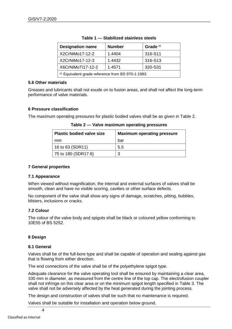
Table 1 — Stabilized stainless steels
Designation name Number Grade a) X2CrNiMo17-12-2 1.4404 316-S11 X2CrNiMo17-12-3 1.4432 316-S13 X6CrNiMoTi17-12-2 1.4571 320-S31 a) Equivalent grade reference from BS 970-1:1983.
5.6 Other materials Greases and lubricants shall not exude on to fusion areas, and shall not affect the long-term performance of valve materials.
6 Pressure classification The maximum operating pressures for plastic bodied valves shall be as given in Table 2.
Table 2 — Valve maximum operating pressures
Plastic bodied valve size Maximum operating pressure mm bar 16 to 63 (SDR11) 5.5 75 to 180 (SDR17.6) 3
7 General properties
7.1 Appearance When viewed without magnification, the internal and external surfaces of valves shall be smooth, clean and have no visible scoring, cavities or other surface defects.
No component of the valve shall show any signs of damage, scratches, pitting, bubbles, blisters, inclusions or cracks.
7.2 Colour The colour of the valve body and spigots shall be black or coloured yellow conforming to 10E55 of BS 5252.
8 Design
8.1 General Valves shall be of the full-bore type and shall be capable of operation and sealing against gas that is flowing from either direction.
The end connections of the valve shall be of the polyethylene spigot type.
Adequate clearance for the valve operating tool shall be ensured by maintaining a clear area, 100 mm in diameter, as measured from the centre line of the top cap. The electrofusion coupler shall not infringe on this clear area or on the minimum spigot length specified in Table 3. The valve shall not be adversely affected by the heat generated during the jointing process.
The design and construction of valves shall be such that no maintenance is required.
Valves shall be suitable for installation and operation below ground.
GIS/V7-2:2020
5 Classified as Internal
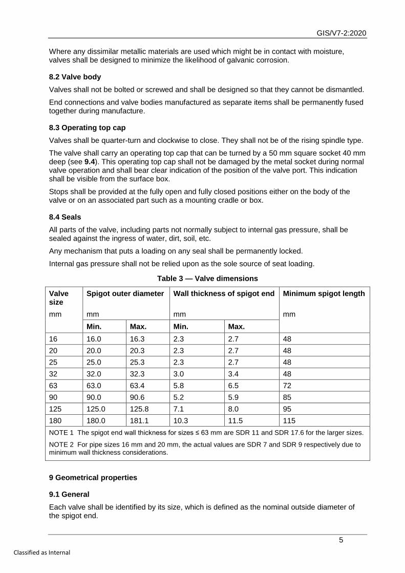
Where any dissimilar metallic materials are used which might be in contact with moisture, valves shall be designed to minimize the likelihood of galvanic corrosion.
8.2 Valve body Valves shall not be bolted or screwed and shall be designed so that they cannot be dismantled.
End connections and valve bodies manufactured as separate items shall be permanently fused together during manufacture.
8.3 Operating top cap Valves shall be quarter-turn and clockwise to close. They shall not be of the rising spindle type.
The valve shall carry an operating top cap that can be turned by a 50 mm square socket 40 mm deep (see 9.4). This operating top cap shall not be damaged by the metal socket during normal valve operation and shall bear clear indication of the position of the valve port. This indication shall be visible from the surface box.
Stops shall be provided at the fully open and fully closed positions either on the body of the valve or on an associated part such as a mounting cradle or box.
8.4 Seals All parts of the valve, including parts not normally subject to internal gas pressure, shall be sealed against the ingress of water, dirt, soil, etc.
Any mechanism that puts a loading on any seal shall be permanently locked.
Internal gas pressure shall not be relied upon as the sole source of seat loading.
Table 3 — Valve dimensions
Valve size
Spigot outer diameter Wall thickness of spigot end Minimum spigot length
mm mm mm mm Min. Max. Min. Max.
16 16.0 16.3 2.3 2.7 48 20 20.0 20.3 2.3 2.7 48 25 25.0 25.3 2.3 2.7 48 32 32.0 32.3 3.0 3.4 48 63 63.0 63.4 5.8 6.5 72 90 90.0 90.6 5.2 5.9 85 125 125.0 125.8 7.1 8.0 95 180 180.0 181.1 10.3 11.5 115 NOTE 1 The spigot end wall thickness for sizes ≤ 63 mm are SDR 11 and SDR 17.6 for the larger sizes.
NOTE 2 For pipe sizes 16 mm and 20 mm, the actual values are SDR 7 and SDR 9 respectively due to minimum wall thickness considerations.
9 Geometrical properties
9.1 General Each valve shall be identified by its size, which is defined as the nominal outside diameter of the spigot end.
GIS/V7-2:2020
6 Classified as Internal
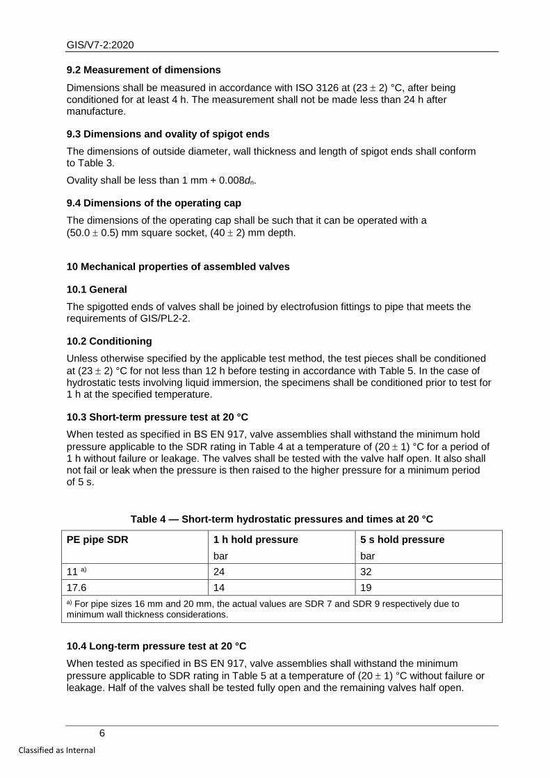
9.2 Measurement of dimensions
Dimensions shall be measured in accordance with ISO 3126 at (23 ± 2) °C, after being conditioned for at least 4 h. The measurement shall not be made less than 24 h after manufacture.
9.3 Dimensions and ovality of spigot ends The dimensions of outside diameter, wall thickness and length of spigot ends shall conform to Table 3.
Ovality shall be less than 1 mm + 0.008dn.
9.4 Dimensions of the operating cap The dimensions of the operating cap shall be such that it can be operated with a (50.0 ± 0.5) mm square socket, (40 ± 2) mm depth.
10 Mechanical properties of assembled valves
10.1 General The spigotted ends of valves shall be joined by electrofusion fittings to pipe that meets the requirements of GIS/PL2-2.
10.2 Conditioning Unless otherwise specified by the applicable test method, the test pieces shall be conditioned at (23 ± 2) °C for not less than 12 h before testing in accordance with Table 5. In the case of hydrostatic tests involving liquid immersion, the specimens shall be conditioned prior to test for 1 h at the specified temperature.
10.3 Short-term pressure test at 20 °C When tested as specified in BS EN 917, valve assemblies shall withstand the minimum hold pressure applicable to the SDR rating in Table 4 at a temperature of (20 ± 1) °C for a period of 1 h without failure or leakage. The valves shall be tested with the valve half open. It also shall not fail or leak when the pressure is then raised to the higher pressure for a minimum period of 5 s.
Table 4 — Short-term hydrostatic pressures and times at 20 °C
PE pipe SDR 1 h hold pressure 5 s hold pressure bar bar 11 a) 24 32 17.6 14 19 a) For pipe sizes 16 mm and 20 mm, the actual values are SDR 7 and SDR 9 respectively due to minimum wall thickness considerations.
10.4 Long-term pressure test at 20 °C When tested as specified in BS EN 917, valve assemblies shall withstand the minimum pressure applicable to SDR rating in Table 5 at a temperature of (20 ± 1) °C without failure or leakage. Half of the valves shall be tested fully open and the remaining valves half open.
GIS/V7-2:2020
7 Classified as Internal
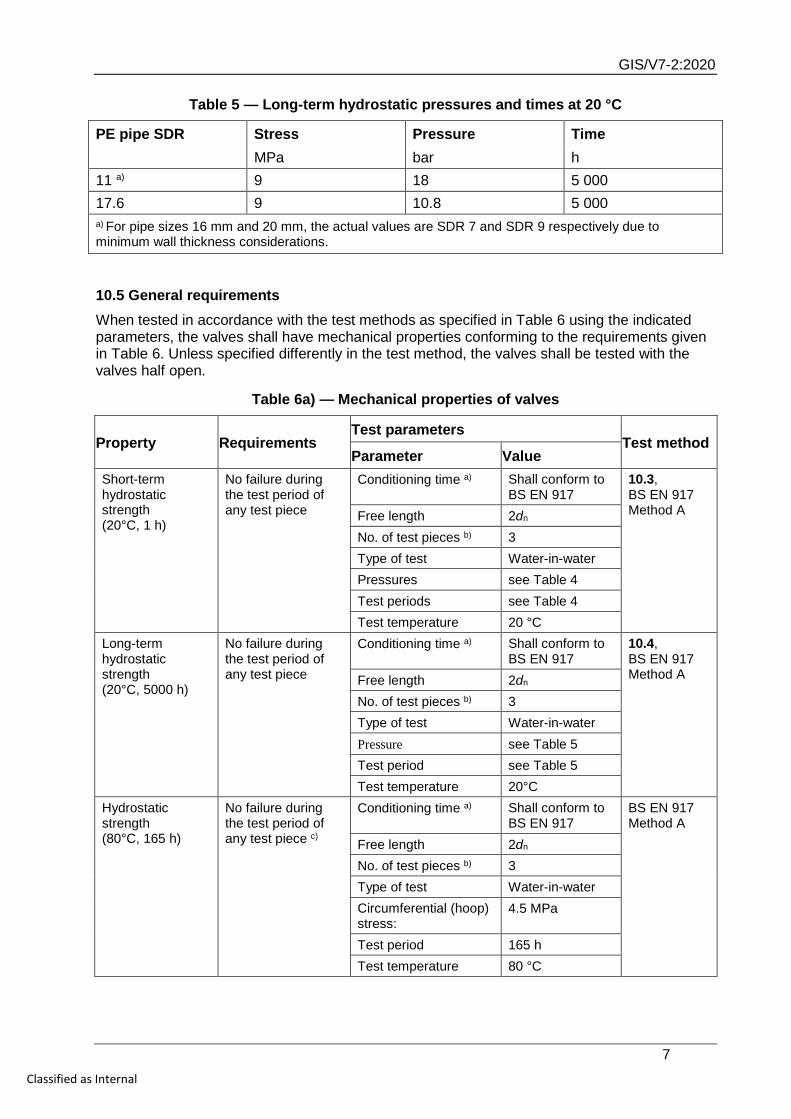
Table 5 — Long-term hydrostatic pressures and times at 20 °C
PE pipe SDR Stress Pressure Time MPa bar h 11 a) 9 18 5 000 17.6 9 10.8 5 000 a) For pipe sizes 16 mm and 20 mm, the actual values are SDR 7 and SDR 9 respectively due to minimum wall thickness considerations.
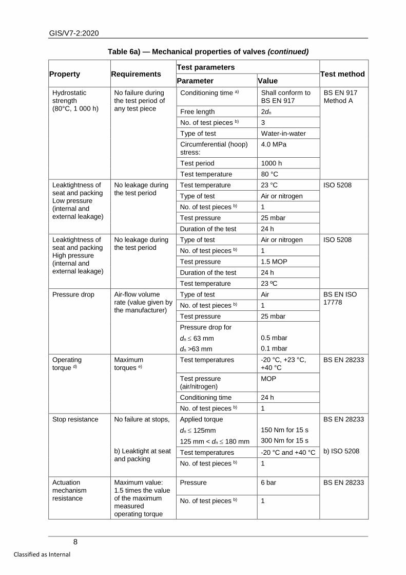
10.5 General requirements When tested in accordance with the test methods as specified in Table 6 using the indicated parameters, the valves shall have mechanical properties conforming to the requirements given in Table 6. Unless specified differently in the test method, the valves shall be tested with the valves half open.
Table 6a) — Mechanical properties of valves
Property Requirements Test parameters
Test method Parameter Value
Short-term hydrostatic strength (20°C, 1 h)
No failure during the test period of any test piece
Conditioning time a) Shall conform to BS EN 917
10.3, BS EN 917 Method A Free length 2dn
No. of test pieces b) 3 Type of test Water-in-water Pressures see Table 4 Test periods see Table 4 Test temperature 20 °C
Long-term hydrostatic strength (20°C, 5000 h)
No failure during the test period of any test piece
Conditioning time a) Shall conform to BS EN 917
10.4, BS EN 917 Method A Free length 2dn
No. of test pieces b) 3 Type of test Water-in-water Pressure see Table 5 Test period see Table 5 Test temperature 20°C
Hydrostatic strength (80°C, 165 h)
No failure during the test period of any test piece c)
Conditioning time a) Shall conform to BS EN 917
BS EN 917 Method A
Free length 2dn No. of test pieces b) 3 Type of test Water-in-water Circumferential (hoop) stress:
4.5 MPa
Test period 165 h Test temperature 80 °C
GIS/V7-2:2020
8 Classified as Internal
Table 6a) — Mechanical properties of valves (continued)
Property Requirements Test parameters
Test method Parameter Value
Hydrostatic strength (80°C, 1 000 h)
No failure during the test period of any test piece
Conditioning time a) Shall conform to BS EN 917
BS EN 917 Method A
Free length 2dn No. of test pieces b) 3 Type of test Water-in-water Circumferential (hoop) stress:
4.0 MPa
Test period 1000 h Test temperature 80 °C
Leaktightness of seat and packing Low pressure (internal and external leakage)
No leakage during the test period
Test temperature 23 °C ISO 5208 Type of test Air or nitrogen No. of test pieces b) 1 Test pressure 25 mbar Duration of the test 24 h
Leaktightness of seat and packing High pressure (internal and external leakage)
No leakage during the test period
Type of test Air or nitrogen ISO 5208 No. of test pieces b) 1 Test pressure 1.5 MOP Duration of the test 24 h Test temperature 23 ºC
Pressure drop Air-flow volume rate (value given by the manufacturer)
Type of test Air BS EN ISO 17778 No. of test pieces b) 1
Test pressure 25 mbar Pressure drop for dn ≤ 63 mm dn >63 mm
0.5 mbar 0.1 mbar
Operating torque d)
Maximum torques e)
Test temperatures -20 °C, +23 °C, +40 °C
BS EN 28233
Test pressure (air/nitrogen)
MOP
Conditioning time 24 h No. of test pieces b) 1
Stop resistance No failure at stops, b) Leaktight at seat and packing
Applied torque dn ≤ 125mm 125 mm < dn ≤ 180 mm
150 Nm for 15 s 300 Nm for 15 s
BS EN 28233 b) ISO 5208 Test temperatures -20 °C and +40 °C
No. of test pieces b) 1
Actuation mechanism resistance
Maximum value: 1.5 times the value of the maximum measured operating torque
Pressure 6 bar BS EN 28233
No. of test pieces b) 1
GIS/V7-2:2020
9 Classified as Internal
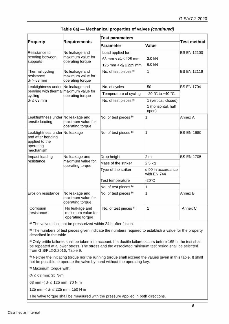
Table 6a) — Mechanical properties of valves (continued)
Property Requirements Test parameters
Test method Parameter Value
Resistance to bending between supports
No leakage and maximum value for operating torque
Load applied for: 63 mm < dn ≤ 125 mm 125 mm < dn ≤ 225 mm
3.0 kN 6.0 kN
BS EN 12100
Thermal cycling resistance dn > 63 mm
No leakage and maximum value for operating torque
No. of test pieces b) 1 BS EN 12119
Leaktightness under bending with thermal cycling dn ≤ 63 mm
No leakage and maximum value for operating torque
No. of cycles 50 BS EN 1704
Temperature of cycling -20 °C to +40 °C
No. of test pieces b) 1 (vertical, closed) 1 (horizontal, half open)
Leaktightness under tensile loading
No leakage and maximum value for operating torque.
No. of test pieces b) 1 Annex A
Leaktightness under and after bending applied to the operating mechanism
No leakage No. of test pieces b) 1 BS EN 1680
Impact loading resistance
No leakage and maximum value for operating torque
Drop height 2 m BS EN 1705
Mass of the striker 2.5 kg
Type of the striker d 90 in accordance with EN 744
Test temperature -20°C
No. of test pieces b) 1
Erosion resistance No leakage and maximum value for operating torque
No. of test pieces b) 1 Annex B
Corrosion resistance
No leakage and maximum value for operating torque
No. of test pieces b) 1 Annex C
a) The valves shall not be pressurized within 24 h after fusion. b) The numbers of test pieces given indicate the numbers required to establish a value for the property described in the table. c) Only brittle failures shall be taken into account. If a ductile failure occurs before 165 h, the test shall be repeated at a lower stress. The stress and the associated minimum test period shall be selected from GIS/PL2-2:2016, Table 9. d) Neither the initiating torque nor the running torque shall exceed the values given in this table. It shall not be possible to operate the valve by hand without the operating key. e) Maximum torque with:
dn ≤ 63 mm: 35 N⋅m
63 mm < dn ≤ 125 mm: 70 N⋅m
125 mm < dn ≤ 225 mm: 150 N⋅m
The valve torque shall be measured with the pressure applied in both directions.
GIS/V7-2:2020
10 Classified as Internal
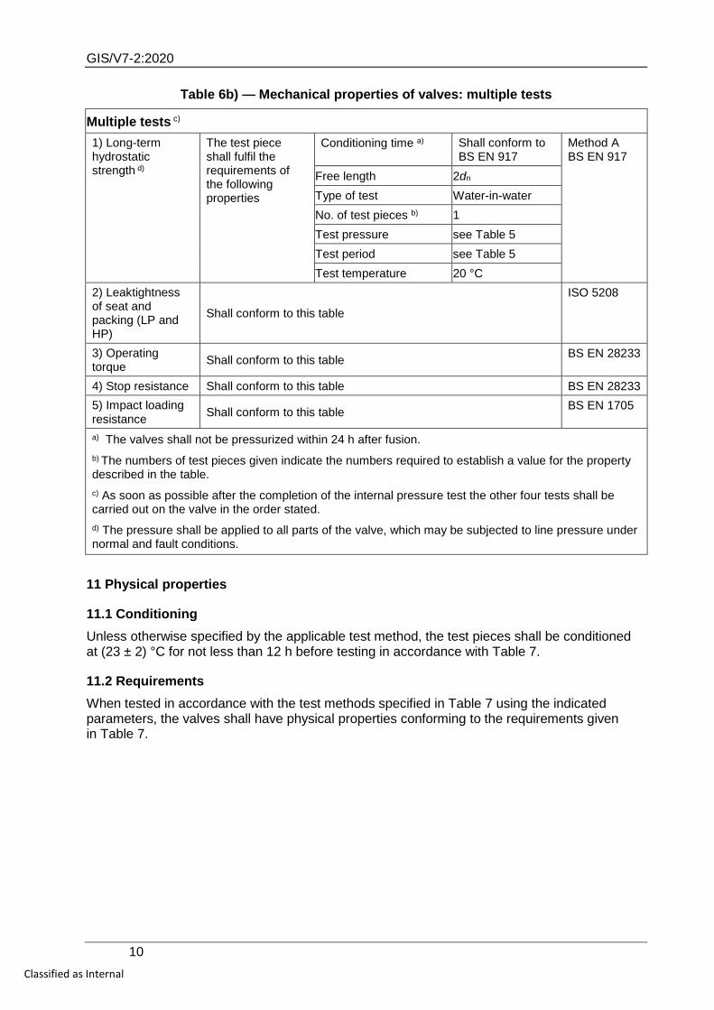
Table 6b) — Mechanical properties of valves: multiple tests
Multiple tests c) 1) Long-term hydrostatic strength d)
The test piece shall fulfil the requirements of the following properties
Conditioning time a) Shall conform to BS EN 917
Method A BS EN 917
Free length 2dn Type of test Water-in-water No. of test pieces b) 1 Test pressure see Table 5 Test period see Table 5 Test temperature 20 °C
2) Leaktightness of seat and packing (LP and HP)
Shall conform to this table
ISO 5208
3) Operating torque Shall conform to this table BS EN 28233
4) Stop resistance Shall conform to this table BS EN 28233 5) Impact loading resistance Shall conform to this table BS EN 1705
a) The valves shall not be pressurized within 24 h after fusion. b) The numbers of test pieces given indicate the numbers required to establish a value for the property described in the table. c) As soon as possible after the completion of the internal pressure test the other four tests shall be carried out on the valve in the order stated. d) The pressure shall be applied to all parts of the valve, which may be subjected to line pressure under normal and fault conditions.
11 Physical properties
11.1 Conditioning Unless otherwise specified by the applicable test method, the test pieces shall be conditioned at (23 ± 2) °C for not less than 12 h before testing in accordance with Table 7.
11.2 Requirements When tested in accordance with the test methods specified in Table 7 using the indicated parameters, the valves shall have physical properties conforming to the requirements given in Table 7.
GIS/V7-2:2020
11 Classified as Internal
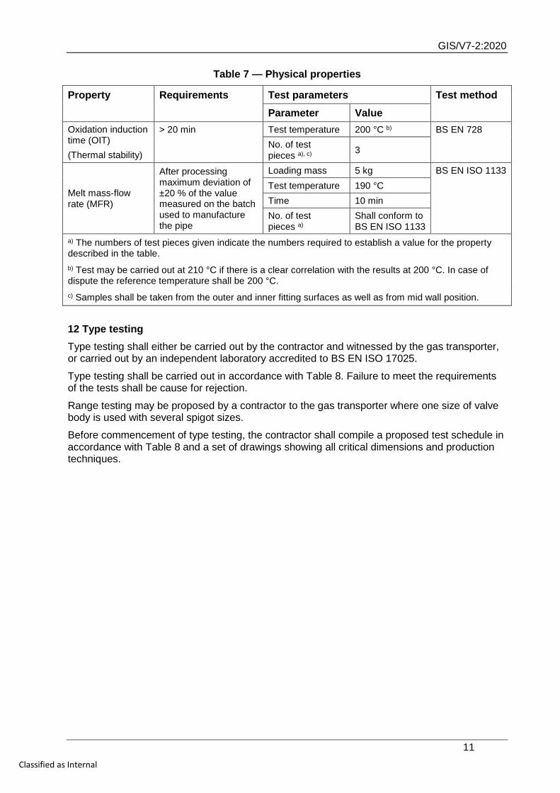
Table 7 — Physical properties
Property Requirements Test parameters Test method Parameter Value
Oxidation induction time (OIT) (Thermal stability)
> 20 min Test temperature 200 °C b) BS EN 728 No. of test pieces a), c) 3
Melt mass-flow rate (MFR)
After processing maximum deviation of ±20 % of the value measured on the batch used to manufacture the pipe
Loading mass 5 kg BS EN ISO 1133 Test temperature 190 °C Time 10 min No. of test pieces a)
Shall conform to BS EN ISO 1133
a) The numbers of test pieces given indicate the numbers required to establish a value for the property described in the table. b) Test may be carried out at 210 °C if there is a clear correlation with the results at 200 °C. In case of dispute the reference temperature shall be 200 °C. c) Samples shall be taken from the outer and inner fitting surfaces as well as from mid wall position.
12 Type testing Type testing shall either be carried out by the contractor and witnessed by the gas transporter, or carried out by an independent laboratory accredited to BS EN ISO 17025.
Type testing shall be carried out in accordance with Table 8. Failure to meet the requirements of the tests shall be cause for rejection.
Range testing may be proposed by a contractor to the gas transporter where one size of valve body is used with several spigot sizes.
Before commencement of type testing, the contractor shall compile a proposed test schedule in accordance with Table 8 and a set of drawings showing all critical dimensions and production techniques.
GIS/V7-2:2020
12 Classified as Internal
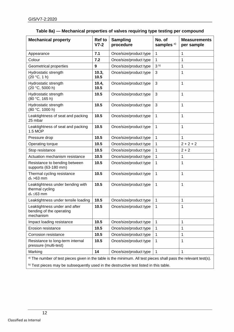
Table 8a) — Mechanical properties of valves requiring type testing per compound
Mechanical property Ref to V7-2
Sampling procedure
No. of samples a)
Measurements per sample
Appearance 7.1 Once/size/product type 1 1 Colour 7.2 Once/size/product type 1 1 Geometrical properties 9 Once/size/product type 3 b) 1 Hydrostatic strength (20 °C, 1 h)
10.3, 10.5
Once/size/product type 3 1
Hydrostatic strength (20 °C, 5000 h)
10.4, 10.5
Once/size/product type 3 1
Hydrostatic strength (80 °C, 165 h)
10.5 Once/size/product type 3 1
Hydrostatic strength (80 °C, 1000 h)
10.5 Once/size/product type 3 1
Leaktightness of seat and packing 25 mbar
10.5 Once/size/product type 1 1
Leaktightness of seat and packing 1.5 MOP
10.5 Once/size/product type 1 1
Pressure drop 10.5 Once/size/product type 1 1 Operating torque 10.5 Once/size/product type 1 2 + 2 + 2 Stop resistance 10.5 Once/size/product type 1 2 + 2 Actuation mechanism resistance 10.5 Once/size/product type 1 1 Resistance to bending between supports (63-180 mm)
10.5 Once/size/product type 1 1
Thermal cycling resistance dn >63 mm
10.5 Once/size/product type 1 1
Leaktightness under bending with thermal cycling dn ≤63 mm
10.5 Once/size/product type 1 1
Leaktightness under tensile loading 10.5 Once/size/product type 1 1 Leaktightness under and after bending of the operating mechanism
10.5 Once/size/product type 1 1
Impact loading resistance 10.5 Once/size/product type 1 1 Erosion resistance 10.5 Once/size/product type 1 1 Corrosion resistance 10.5 Once/size/product type 1 1 Resistance to long-term internal pressure (multi-test)
10.5 Once/size/product type 1 1
Marking 14 Once/size/product type 1 1 a) The number of test pieces given in the table is the minimum. All test pieces shall pass the relevant test(s). b) Test pieces may be subsequently used in the destructive test listed in this table.
GIS/V7-2:2020
13 Classified as Internal
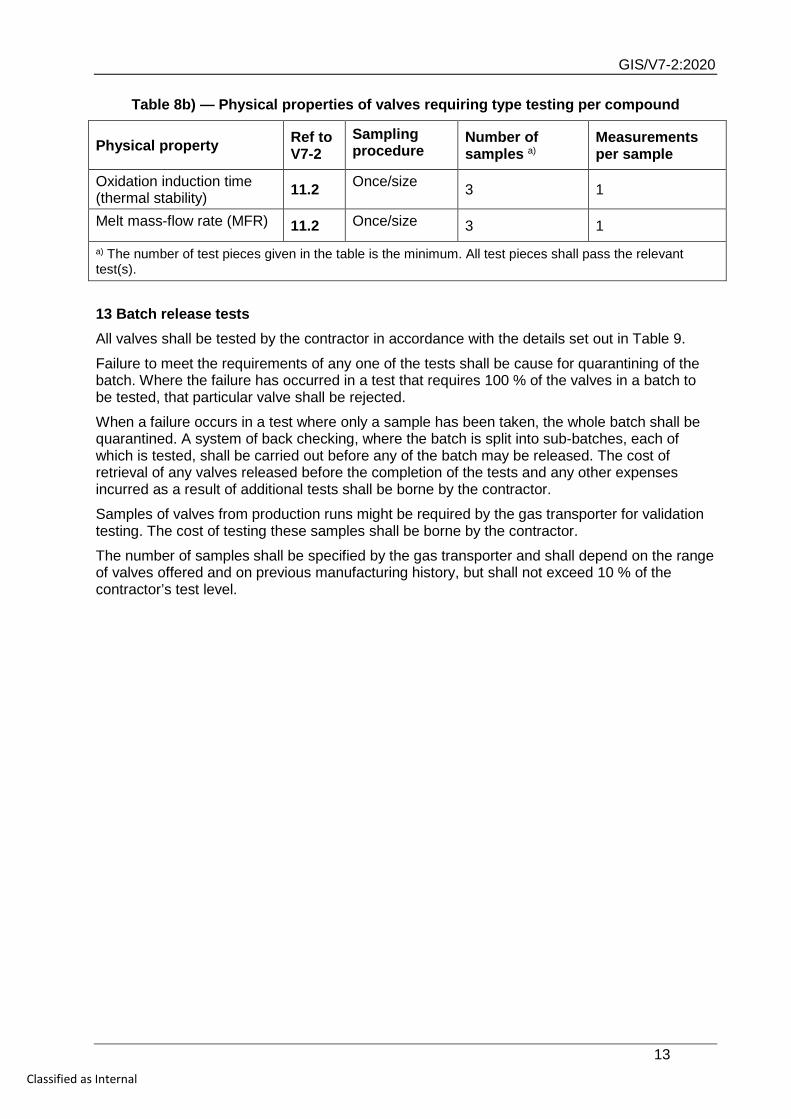
Table 8b) — Physical properties of valves requiring type testing per compound
Physical property Ref to V7-2
Sampling procedure
Number of samples a)
Measurements per sample
Oxidation induction time (thermal stability) 11.2 Once/size 3 1
Melt mass-flow rate (MFR) 11.2 Once/size 3 1 a) The number of test pieces given in the table is the minimum. All test pieces shall pass the relevant test(s).
13 Batch release tests All valves shall be tested by the contractor in accordance with the details set out in Table 9.
Failure to meet the requirements of any one of the tests shall be cause for quarantining of the batch. Where the failure has occurred in a test that requires 100 % of the valves in a batch to be tested, that particular valve shall be rejected.
When a failure occurs in a test where only a sample has been taken, the whole batch shall be quarantined. A system of back checking, where the batch is split into sub-batches, each of which is tested, shall be carried out before any of the batch may be released. The cost of retrieval of any valves released before the completion of the tests and any other expenses incurred as a result of additional tests shall be borne by the contractor.
Samples of valves from production runs might be required by the gas transporter for validation testing. The cost of testing these samples shall be borne by the contractor.
The number of samples shall be specified by the gas transporter and shall depend on the range of valves offered and on previous manufacturing history, but shall not exceed 10 % of the contractor’s test level.
GIS/V7-2:2020
14 Classified as Internal
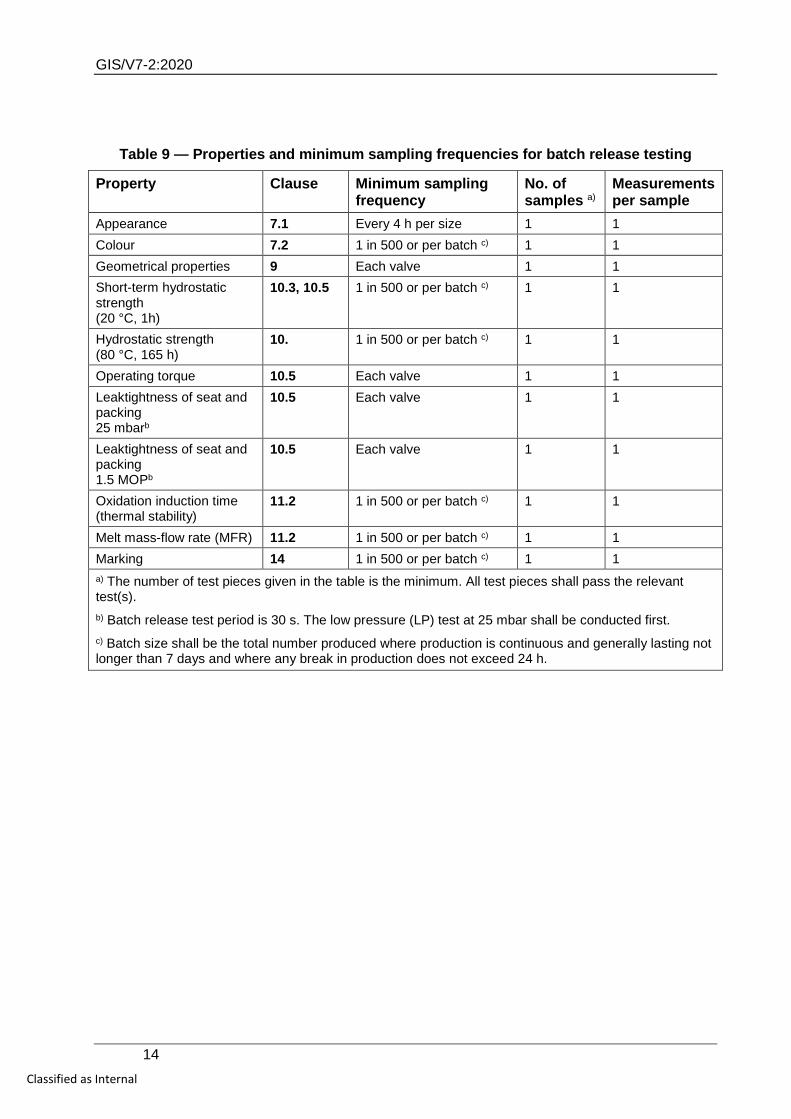
Table 9 — Properties and minimum sampling frequencies for batch release testing
Property Clause Minimum sampling frequency
No. of samples a)
Measurements per sample
Appearance 7.1 Every 4 h per size 1 1 Colour 7.2 1 in 500 or per batch c) 1 1 Geometrical properties 9 Each valve 1 1 Short-term hydrostatic strength (20 °C, 1h)
10.3, 10.5 1 in 500 or per batch c) 1 1
Hydrostatic strength (80 °C, 165 h)
10. 1 in 500 or per batch c) 1 1
Operating torque 10.5 Each valve 1 1 Leaktightness of seat and packing 25 mbarb
10.5 Each valve 1 1
Leaktightness of seat and packing 1.5 MOPb
10.5 Each valve 1 1
Oxidation induction time (thermal stability)
11.2 1 in 500 or per batch c) 1 1
Melt mass-flow rate (MFR) 11.2 1 in 500 or per batch c) 1 1 Marking 14 1 in 500 or per batch c) 1 1 a) The number of test pieces given in the table is the minimum. All test pieces shall pass the relevant test(s). b) Batch release test period is 30 s. The low pressure (LP) test at 25 mbar shall be conducted first. c) Batch size shall be the total number produced where production is continuous and generally lasting not longer than 7 days and where any break in production does not exceed 24 h.
GIS/V7-2:2020
15 Classified as Internal
14 Marking and instructions
14.1 All valves conforming to GIS/V7-2 shall be permanently marked with the following information:
a) the name or trademark of the manufacturer or their appointed agent;
b) the valve size, e.g. “63 mm”;
c) SDR value.
14.2 A label or bag associated with each valve conforming to GIS/V7-2 shall be permanently marked with the following information, if the information cannot be marked on the valve itself:
a) the number and date of this standard, i.e. GIS/V7-2:2020 1);
b) the manufacturer’s contact details;
c) batch number or code, e.g. “1234”;
d) if weight exceeds 10 kg, valve weight in kg, e.g. “15 kg”;
e) where authorized, the product conformity mark of a third party certification body, e.g. BSI Kitemark. NOTE Attention is drawn to the advantages of using third party certification of conformance to a standard.”
A yellow label shall be securely affixed to each valve to indicate the maximum operating pressure and the range of pipe SDRs approved for electrofusion jointing.
All marking shall remain legible under normal handling, storage and installation procedures. The method of marking shall not prevent the valve from conforming to this standard. There shall be no marking on the minimum spigot length.
The contractor shall supply leaflets, in English, detailing approved assembly instructions. This shall include details of torque requirements, restraint requirements and any other pertinent assembly information.
15 Protection and storage of valves Valves shall be individually bagged to protect the product during transit or storage. The valve packaging shall contain the approved assembly instructions.
The valve shall be stored so as to avoid damage. Particular attention shall be given to the prevention of damage to spigot ends and to protection from the effects of sunlight.
1) Marking GIS/V7-2:2020 on or in relation to a product represents a manufacturer’s declaration of conformity, i.e. a claim by or on behalf of the manufacturer that the product meets the requirements of the standard. The accuracy of the claim is therefore solely the responsibility of the person making the claim. Such a declaration is not to be confused with third party certification of conformity, which may also be desirable.
GIS/V7-2:2020
16 Classified as Internal
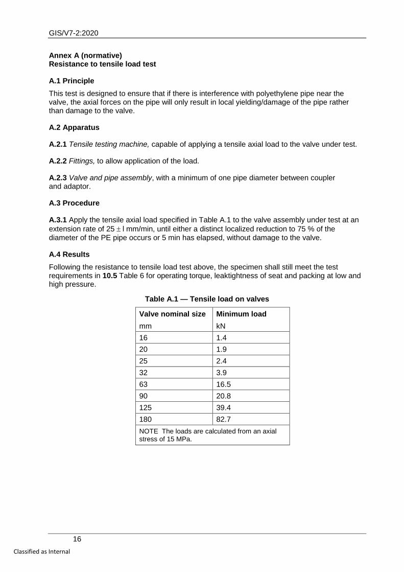
Annex A (normative) Resistance to tensile load test
A.1 Principle This test is designed to ensure that if there is interference with polyethylene pipe near the valve, the axial forces on the pipe will only result in local yielding/damage of the pipe rather than damage to the valve.
A.2 Apparatus
A.2.1 Tensile testing machine, capable of applying a tensile axial load to the valve under test.
A.2.2 Fittings, to allow application of the load.
A.2.3 Valve and pipe assembly, with a minimum of one pipe diameter between coupler and adaptor.
A.3 Procedure
A.3.1 Apply the tensile axial load specified in Table A.1 to the valve assembly under test at an extension rate of 25 ± l mm/min, until either a distinct localized reduction to 75 % of the diameter of the PE pipe occurs or 5 min has elapsed, without damage to the valve.
A.4 Results Following the resistance to tensile load test above, the specimen shall still meet the test requirements in 10.5 Table 6 for operating torque, leaktightness of seat and packing at low and high pressure.
Table A.1 — Tensile load on valves
Valve nominal size Minimum load mm kN 16 1.4 20 1.9 25 2.4 32 3.9 63 16.5 90 20.8 125 39.4 180 82.7 NOTE The loads are calculated from an axial stress of 15 MPa.
GIS/V7-2:2020
17 Classified as Internal
Annex B (normative) Erosion resistance
B.1 General In this test, the valve is subjected to erosion by dust-laden air to see if this prevents it from passing the required levels for ease of operation, leakage to atmosphere and internal leakage.
B.2 Apparatus
B.2.1 Means of injecting dust into the gas, upstream of the valve, pressure regulation and flow control.
B.2.2 Dust for injection, consisting of steel grit capable of passing through a 600 µm sieve but not through a 300 µm sieve. Hardness value should be in the range of 700 – 1000 HV (58.5 – 65.5 HRC).
B.2.3 Test valve(s)/rig.
B.2.4 Pressure regulator.
B.2.5 Flow control valve.
B.3 Procedure
B.3.1 Set the pressure regulator to maintain a 150 mbar pressure into the test rig.
B.3.2 Set the flow control valve to give a 25 m/s gas velocity in the pipe when the valve is in the fully open position and the dust injection rate is 10 g/min.
B.3.3 Subject the valve to dust laden gas under the above conditions for a period of 30 min.
B.3.4 Leave the valve in the open position for a period of 24 h.
B.4 Results The valve shall meet the test requirements in 10.5 Table 6 for operating torque, leaktightness of seat and packing at low and high pressure.
The valve shall not be opened or closed before it is subjected to the operating torque test, as this would reduce the friction and loosen the valve.
GIS/V7-2:2020
18 Classified as Internal
Annex C (normative) Corrosion resistance
C.1 Principle Where any part of the valve is made of dissimilar metals or where exposed metal components are used, this test is for determining whether the valve is resistant to corrosion in salt water.
C.2 Apparatus
C.2.1 Temperature-controlled bath, containing the specified solution at the specified temperature at (50 ± 1) °C.
C.2.2 Means of maintaining a dry air environment at standard conditions (see Clause 10).
C.2.3 Valve, with pipe pups, each of a length at least twice the outside pipe diameter, of a material conforming to GIS/PL2-1, and electrofusion joints with fittings conforming to GIS/PL2-4.
C.2.4 End connections, pressure-tight and load-bearing, capable of accepting a closure which has a pressurization/air release tapping.
C.3 Procedure
C.3.1 Immerse the valve in the (3 ± 1 )% sodium chloride solution bath for 15 months at 50 °C. Ensure that the solution has access to all external parts of the valve, including, for example, those parts, that might be shrouded, though not sealed, by the top cap.
C.3.2 After 1 h, vent the internal pressure to atmosphere due to the temperature change.
C.3.3 With the vent open, operate the valve once to ensure venting of any body cavity, whilst remaining immersed in the bath.
C.3.4 Leave the valve in the closed position.
C.3.5 Remove the valve from immersion and dry it for two weeks at (23 ± 2) °C in dry air.
C.4 Results After being dried, the valve shall meet the test requirements in 10.5 Table 6 for operating torque, leaktightness of seat and packing at low and high pressure.
The valve shall not be opened or closed before it is subjected to the operating torque test, as this would reduce the friction and loosen the valve.