Embed Size (px)
Citation preview
GE Industrial Solutions
Gas Insulated Medium Voltage SwitchgearLeading the future of electrification


GEGE is a diversified organization covering a myriad of market segments, including infrastructure,
finance and media. From energy, water, transportation and health to access to money and
information, GE serves customers in more than 100 countries and employs more than 300,000
people worldwide.
The company traces its beginnings from Thomas A. Edison, who established the Edison Electric Light
Company in 1878. In 1892, a merger of Edison General Electric Company and Thomson-Houston
Electric Company created the General Electric Company. GE is the only company listed in the Dow
Jones Industrial Index today that was also included in the original index in 1896.
Industrial SolutionsGE Industrial Solutions, a division of GE Energy Management, is a global leading provider in
power distribution, offering a wide range of services and products which include medium and low
voltage power distribution equipment and components, motor & control systems and service
products that are safe, reliable and offer high performance.
Honour
2007 World’s Best R&D Companies
2011 World’s Most Admired Companies
2011 Best Global Brand
2008 World’s Most Respected Companies
2010 World's Most Innovative Companies
2009 World’s Most Respected Companies

Leading the future of electrification
Gas Insulated Medium Voltage Switchgear
ContentsGeneral Introduction
About GE
GE Industrial Solutions
Product DescriptionOverview . . . . . . . . . . . . . . . . . . . . . . . . . . . . . . . . . . . . . . . . . . . . . . . 2
Environment and Energy Efficiency . . . . . . . . . . . . . . . . . . . . . . . 3
Operating Conditions . . . . . . . . . . . . . . . . . . . . . . . . . . . . . . . . . . . . 4
SecoCube Advantage . . . . . . . . . . . . . . . . . . . . . . . . . . . . . . . . . . . . 6
Standards . . . . . . . . . . . . . . . . . . . . . . . . . . . . . . . . . . . . . . . . . . . . . . . 7
Switchgear Technical Specifications . . . . . . . . . . . . . . . . . . . . . . 8
Advanced Manufacturing and Testing Process . . . . . . . . . . .10
Product IntroductionModular Design . . . . . . . . . . . . . . . . . . . . . . . . . . . . . . . . . . . . . . . .13
Structure . . . . . . . . . . . . . . . . . . . . . . . . . . . . . . . . . . . . . . . . . . . . . . .14
Switchgear Front Panel . . . . . . . . . . . . . . . . . . . . . . . . . . . . . . . . .16
Embedded SecoVac-G Vacuum Circuit Breaker . . . . . . . . . .18
IST Three-position Switch . . . . . . . . . . . . . . . . . . . . . . . . . . . . . . .21
Busbar System . . . . . . . . . . . . . . . . . . . . . . . . . . . . . . . . . . . . . . . . .23
Inner-cone Cable Connection System . . . . . . . . . . . . . . . . . . .24
Surge Arrester . . . . . . . . . . . . . . . . . . . . . . . . . . . . . . . . . . . . . . . . . .24
Voltage Transformer . . . . . . . . . . . . . . . . . . . . . . . . . . . . . . . . . . . .25
Current Transformer . . . . . . . . . . . . . . . . . . . . . . . . . . . . . . . . . . . .26
Gas System . . . . . . . . . . . . . . . . . . . . . . . . . . . . . . . . . . . . . . . . . . . .27
Pressure Relief System . . . . . . . . . . . . . . . . . . . . . . . . . . . . . . . . . .28
Multilin 3 Series. . . . . . . . . . . . . . . . . . . . . . . . . . . . . . . . . . . . . . . . .30
Multilin 650 Family . . . . . . . . . . . . . . . . . . . . . . . . . . . . . . . . . . . . .33
Accessories . . . . . . . . . . . . . . . . . . . . . . . . . . . . . . . . . . . . . . . . . . . .38
Testing Tools . . . . . . . . . . . . . . . . . . . . . . . . . . . . . . . . . . . . . . . . . . .38
Typical solutionStandard SecoCube Typical Panels . . . . . . . . . . . . . . . . . . . . . .40
Green SecoCube Typical Panels . . . . . . . . . . . . . . . . . . . . . . . . .41
Typical Schemes . . . . . . . . . . . . . . . . . . . . . . . . . . . . . . . . . . . . . . .43
SecoCube DimensionsSecoCube Dimensions . . . . . . . . . . . . . . . . . . . . . . . . . . . . . . . . . .49
SecoCube Control Circuit Schematic Drawing . . . . . . . . . . . .51
SecoCube Installation Foundation . . . . . . . . . . . . . . . . . . . . . . .53
SecoCube Shipping Data . . . . . . . . . . . . . . . . . . . . . . . . . . . . . . . .59
Prod
uct D
escr
iptio
n
02
SecoCube 36kV Gas Insulated Medium Voltage Switchgear
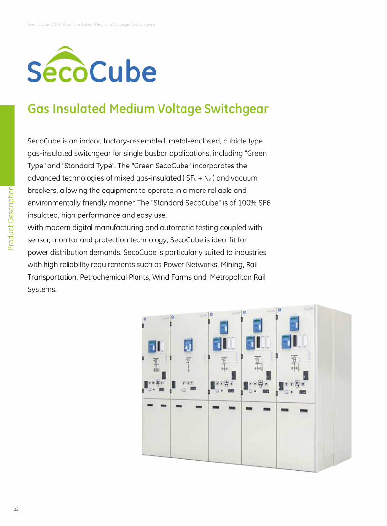
SecoCube is an indoor, factory-assembled, metal-enclosed, cubicle type
gas-insulated switchgear for single busbar applications, including "Green
Type" and "Standard Type". The "Green SecoCube" incorporates the
advanced technologies of mixed gas-insulated ( SF6 + N2 ) and vacuum
breakers, allowing the equipment to operate in a more reliable and
environmentally friendly manner. The "Standard SecoCube" is of 100% SF6
insulated, high performance and easy use.
With modern digital manufacturing and automatic testing coupled with
sensor, monitor and protection technology, SecoCube is ideal fit for
power distribution demands. SecoCube is particularly suited to industries
with high reliability requirements such as Power Networks, Mining, Rail
Transportation, Petrochemical Plants, Wind Farms and Metropolitan Rail
Systems.
Gas Insulated Medium Voltage Switchgear
Prod
uct D
escr
iptio
n
03
SecoCube 36kV Gas Insulated Medium Voltage Switchgear
Environment and Energy Efficiency
Envi
ronm
ent
Reduce Greenhouse Gas EmissionsSecoCube incorporates the advanced technologies of mixed gas-
insulated ( SF6 + N2 ) and vacuum breakers, a fundamental choice
made by GE to assist in reducing the greenhouse effect. SF6 (sulphur-
hexafluoride ) is on the list of greenhouse gasses in the Kyoto Protocol,
with a Global Warming Potential ( GWP ) of 23,000. Many other medium
voltage switchgear systems use SF6 gas as the only insulating medium.
Leakage of SF6 gas from switchgear contributes to the threat of the
greenhouse effect and associated climate change.
With our commitment to protection of the environment, SecoCube
helps reduce greenhouse gas emissions by utilising mixed gas-
insulated technology together with vacuum switching technology.
A 50% reduction in SF6 is achieved by using Nitrogen ( N2 ) in the
SecoCube mixed gas-insulated breakers. Nitrogen is the largest
component of air and its arc decomposition product is non-toxic.
Joined together by plug-in connectors and the modular nature of the
panels ensures ease of installation and extension without the need for
extra gas handling activities on-site.
Environmental, Health And Safety Of Materials GE has strict processes to ensure regulations for the environment,
health and safety of materials used during product design and
manufacturing are observed. Only re-usable and/or recyclable
materials are used in producing SecoCube switchgear. It reflects GE's
commitment to environmental challenges while delivering valuable
products and services to the customer.
Low Energy ConsumptionHeat loss (I2R) is mainly caused by circuit resistance, however the
main circuit resistance of the SecoCube is only one-third to one-half of
equivalent air-insulated switchgear. This results in SecoCube exhibiting
lower heat losses.
With an optimized structural design for heat transfer along with
surface treatments, SecoCube achieves reliable heat dissipation by
natural cooling. Fan-forced ventilation is not required for SecoCube at
any ratings, including the 2500A switchgear. Energy is saved during
switchgear operation whilst operating reliability is enhanced.
Prod
uct D
escr
iptio
n
04
SecoCube 36kV Gas Insulated Medium Voltage Switchgear
Operating Conditions
Normal operating conditionsThe switchgear is fundamentally designed for the normal service conditions for
indoor switchgear to GB 3906. The following limit values, among others, apply:
● Ambient temperature
- Maximum +40℃
- Minimum -25℃
- Daily average maximum temperature +35℃
● The maximum site altitude is 1000 m above sea level
● Humidity
- Daily average relative humidity ≤ 95%
- Monthly average relative humidity ≤ 90%
- Daily average vapor pressure ≤ 2.2×10⁻³MPa
- Monthly average vapor pressure ≤ 1.8×10⁻³MPa
● The surrounding environment shall not suffer obvious pollution caused by
corrosive, flammable or explosive gas
● Electromagnetic interference in the secondary system shall be less than 1.6kV
● Pollution level is not more than class II identified by GB/T 5582
Special Operating ConditionsHigh altitude ( >1000m a.s.l. ) SecoCube is available. Special operating conditions
apply, please contact GE in advance.
The manufacturer and end-user must agree about special operating conditions
which deviate from operation under normal conditions. The manufacturer/
supplier must be consulted in advance if especially severe operating conditions
are involved.
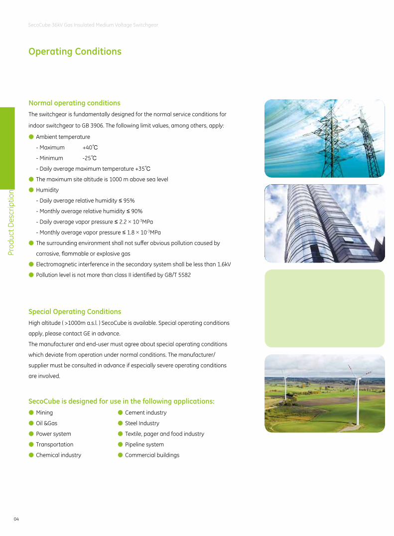
SecoCube is designed for use in the following applications: ● Mining
● Oil &Gas
● Power system
● Transportation
● Chemical industry
● Cement industry
● Steel Industry
● Textile, pager and food industry
● Pipeline system
● Commercial buildings
Prod
uct D
escr
iptio
n
05
SecoCube 36kV Gas Insulated Medium Voltage Switchgear
Appl
icat
ions
Prod
uct D
escr
iptio
n
06
SecoCube 36kV Gas Insulated Medium Voltage Switchgear
SecoCube Advantage
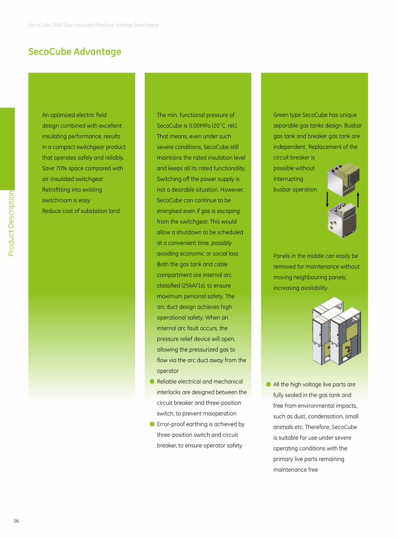
Maximum Safety For Operator And Equipment
● The min. functional pressure of
SecoCube is 0.00MPa (20˚C, rel.).
That means, even under such
severe conditions, SecoCube still
maintains the rated insulation level
and keeps all its rated functionality.
Switching off the power supply is
not a desirable situation. However,
SecoCube can continue to be
energised even if gas is escaping
from the switchgear. This would
allow a shutdown to be scheduled
at a convenient time, possibly
avoiding economic or social loss
● Both the gas tank and cable
compartment are internal arc
classified (25kA/1s), to ensure
maximum personal safety. The
arc duct design achieves high
operational safety. When an
internal arc fault occurs, the
pressure relief device will open,
allowing the pressurized gas to
flow via the arc duct away from the
operator
● Reliable electrical and mechanical
interlocks are designed between the
circuit breaker and three-position
switch, to prevent misoperation
● Error-proof earthing is achieved by
three-position switch and circuit
breaker, to ensure operator safety
70% Reduction In Switchroom Size
● An optimized electric field
design combined with excellent
insulating performance, results
in a compact switchgear product
that operates safely and reliably.
● Save 70% space compared with
air-insulated switchgear
● Retrofitting into existing
switchroom is easy
● Reduce cost of substation land
Easy Installation/Low Operation And Maintenance Cost
● Green type SecoCube has unique
separable gas tanks design. Busbar
gas tank and breaker gas tank are
independent. Replacement of the
circuit breaker is
possible without
interrupting
busbar operation
● Panels in the middle can easily be
removed for maintenance without
moving neighbouring panels,
increasing availability
● All the high voltage live parts are
fully sealed in the gas tank and
free from environmental impacts,
such as dust, condensation, small
animals etc. Therefore, SecoCube
is suitable for use under severe
operating conditions with the
primary live parts remaining
maintenance free
Prod
uct D
escr
iptio
n
07
SecoCube 36kV Gas Insulated Medium Voltage Switchgear
Standards
SecoCube complies with the standards and specifications for factory assembled metal enclosed switchgear and
has been type tested in accordance with the GB standards as given below.
All other corresponding IEC publications, national or local safety regulations must be followed during the
installation and operation of the switchgear. In addition, any project specific advice from GE must be considered.
GB/T 11022 (IEC 62271-1) Common specifications for high-voltage switchgear and controlgear standards
GB 3906 (IEC 62271-200) A.C. metal-enclosed switchgear for rated voltages of 3.6~40.5kV
GB 1985 (IEC 62271-102) Alternating current high-voltage disconnectors and earthing switches
GB 1984 (IEC 62271-100) Alternating current high-voltage circuit breakers
GB 8905 (IEC 60480) The guide for processing and measuring SF6 gas in power apparatus
GB 28537 (IEC 62271-303) Test guide of SF6 gas tightness for high-voltage switchgear
GB 12022 (IEC 376, 376A, 376B) Sulphur hexafluoride for industrial use
DL/T 593 Common specifications for high-voltage switchgear and controlgear
DL/T 404 Indoor AC High Voltage Switchboard Ordering requirement
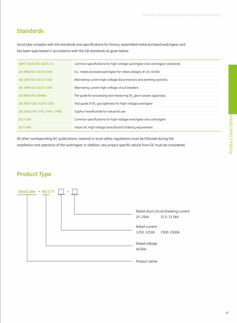
SecoCube 40.5 / T- -
Rated short circuit breaking current:25: 25kA 31.5: 31.5kA
Rated current:1250: 1250A 2500: 2500A
Rated voltage:40.5kA
Product series
Product Type
Prod
uct D
escr
iptio
n
08
SecoCube 36kV Gas Insulated Medium Voltage Switchgear
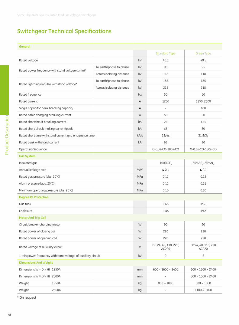
Switchgear Technical Specifications
General
Standard Type Green Type
Rated voltage kV 40.5 40.5
Rated power frequency withstand voltage (1min)*To earth/phase to phase kV 95 95
Across isolating distance kV 118 118
Rated lightning impulse withstand voltage*To earth/phase to phase kV 185 185
Across isolating distance kV 215 215
Rated frequency Hz 50 50
Rated current A 1250 1250, 2500
Single capacitor bank breaking capacity A - 400
Rated cable charging breaking current A 50 50
Rated shortcircuit breaking current kA 25 31.5
Rated short circuit making current(peak) kA 63 80
Rated short time withstand current and endurance time kA/s 25/4s 31.5/3s
Rated peak withstand current kA 63 80
Operating Sequence O-0.3s-CO-180s-CO O-0.3s-CO-180s-CO
Gas System
Insulated gas 100%SF6 50%SF6+50%N2
Annual leakage rate %/Y ≤ 0.1 ≤ 0.1
Rated gas pressure (abs, 20˚C) MPa 0.12 0.12
Alarm pressure (abs, 20˚C) MPa 0.11 0.11
Minimum operating pressure (abs, 20˚C) MPa 0.10 0.10
Degree Of Protection
Gas tank IP65 IP65
Enclosure IP4X IP4X
Motor And Trip Coil
Circuit breaker charging motor W 90 90
Rated power of closing coil W 220 220
Rated power of opening coil W 220 220
Rated voltage of auxiliary circuit V DC 24, 48, 110, 220;AC220
DC24, 48, 110, 220AC220
1 min power frequency withstand voltage of auxiliary circuit kV 2 2
Dimensions And Weight
Dimensions(W×D×H) 1250A mm 600×1600×2400 600×1500×2400
Dimensions(W×D×H) 2500A mm - 800×1500×2400
Weight 1250A kg 800 ~ 1000 800 ~ 1000
Weight 2500A kg - 1100 ~ 1400
* On request
Prod
uct D
escr
iptio
n
09
SecoCube 36kV Gas Insulated Medium Voltage Switchgear
Internal Arc Classification A FLR 31.5kA/0.5s
Type of accessibility A Switchgear in closed electrical service location, access "for authorized personnel only"
according to IEC 62271-200
F Access from the front
L Access from the lateral
R Access from the rear
Loss Of Service Continuity Category (LSC) According To IEC 62271-200
Cable compartments LSC2B
Gas tanks Not applicable
LSC category defines the possibility to keep other compartments and/or functional units energized when
opening a main circuit compartment.
Gas tank is fully sealed for its service life and cannot be opened under service conditions, otherwise, it will
lose its functionality. Therefore, there is no criterion for LSC category of inaccessible compartments. The LSC
category is not applicable for gas tanks.
Cable compartment of SecoCube is LSC2B because it may remain energized when other accessible
compartment of the panel is open.
Switchgear Partition Class Acc. To IEC 62271-200 PM
Partition class in IEC 62271-200 defines whether metallic or non-metallic materials for separation to live parts
is used. SecoCube provides continuous metallic partitions, intended to be earthed, between opened accessible
compartments and live parts of the main circuit.
Prod
uct D
escr
iptio
n
10
SecoCube 36kV Gas Insulated Medium Voltage Switchgear
Advanced Manufacturing and Testing Process
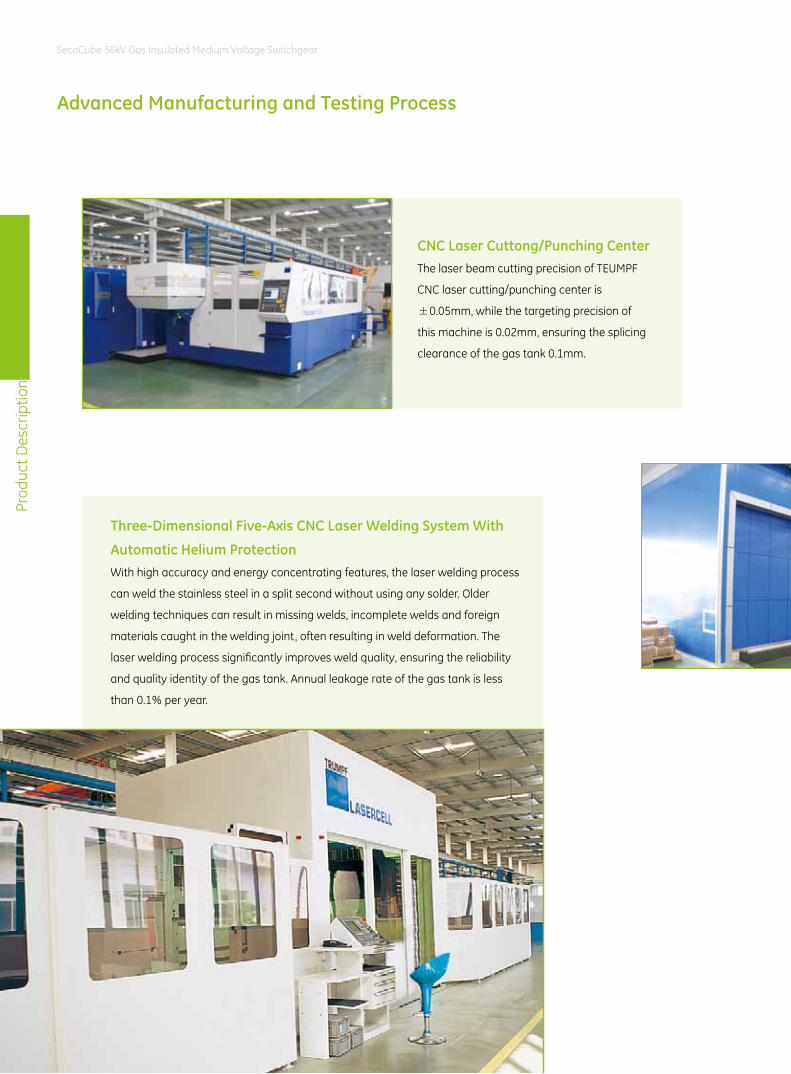
CNC Laser Cuttong/Punching CenterThe laser beam cutting precision of TEUMPF
CNC laser cutting/punching center is
±0.05mm, while the targeting precision of
this machine is 0.02mm, ensuring the splicing
clearance of the gas tank 0.1mm.
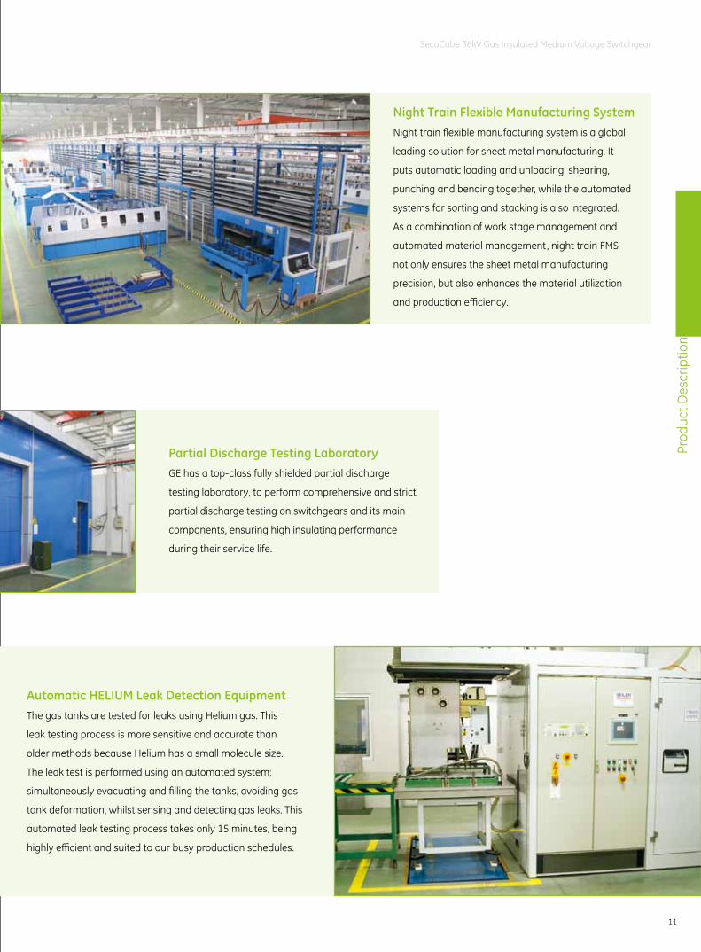
Three-Dimensional Five-Axis CNC Laser Welding System With
Automatic Helium ProtectionWith high accuracy and energy concentrating features, the laser welding process
can weld the stainless steel in a split second without using any solder. Older
welding techniques can result in missing welds, incomplete welds and foreign
materials caught in the welding joint, often resulting in weld deformation. The
laser welding process significantly improves weld quality, ensuring the reliability
and quality identity of the gas tank. Annual leakage rate of the gas tank is less
than 0.1% per year.
Prod
uct D
escr
iptio
n
11
SecoCube 36kV Gas Insulated Medium Voltage Switchgear
Partial Discharge Testing LaboratoryGE has a top-class fully shielded partial discharge
testing laboratory, to perform comprehensive and strict
partial discharge testing on switchgears and its main
components, ensuring high insulating performance
during their service life.
Automatic HELIUM Leak Detection EquipmentThe gas tanks are tested for leaks using Helium gas. This
leak testing process is more sensitive and accurate than
older methods because Helium has a small molecule size.
The leak test is performed using an automated system;
simultaneously evacuating and filling the tanks, avoiding gas
tank deformation, whilst sensing and detecting gas leaks. This
automated leak testing process takes only 15 minutes, being
highly efficient and suited to our busy production schedules.
Night Train Flexible Manufacturing SystemNight train flexible manufacturing system is a global
leading solution for sheet metal manufacturing. It
puts automatic loading and unloading, shearing,
punching and bending together, while the automated
systems for sorting and stacking is also integrated.
As a combination of work stage management and
automated material management, night train FMS
not only ensures the sheet metal manufacturing
precision, but also enhances the material utilization
and production efficiency.
Prod
uct I
ntro
duct
ion
12
SecoCube 36kV Gas Insulated Medium Voltage Switchgear
Product IntroductionModular Design . . . . . . . . . . . . . . . . . . . . . . . . . . . . . . . . . . . . . . . . . . . . . .13
Structure . . . . . . . . . . . . . . . . . . . . . . . . . . . . . . . . . . . . . . . . . . . . . . . . . . . .14
Switchgear Front Panel . . . . . . . . . . . . . . . . . . . . . . . . . . . . . . . . . . . . . . .16
Embedded SecoVac-G Vacuum Circuit Breaker . . . . . . . . . . . . . . . .18
IST Three-position Switch . . . . . . . . . . . . . . . . . . . . . . . . . . . . . . . . . . . . .21
Busbar System . . . . . . . . . . . . . . . . . . . . . . . . . . . . . . . . . . . . . . . . . . . . . . .23
Inner-cone Cable Connection System . . . . . . . . . . . . . . . . . . . . . . . . .24
Surge Arrester. . . . . . . . . . . . . . . . . . . . . . . . . . . . . . . . . . . . . . . . . . . . . . . .24
Voltage Transformer . . . . . . . . . . . . . . . . . . . . . . . . . . . . . . . . . . . . . . . . .25
Current Transformer . . . . . . . . . . . . . . . . . . . . . . . . . . . . . . . . . . . . . . . . . .26
Gas System . . . . . . . . . . . . . . . . . . . . . . . . . . . . . . . . . . . . . . . . . . . . . . . . . .27
Pressure Relief System . . . . . . . . . . . . . . . . . . . . . . . . . . . . . . . . . . . . . . . .28
Multilin 3 Series . . . . . . . . . . . . . . . . . . . . . . . . . . . . . . . . . . . . . . . . . . . . . .30
Multilin 650 Family . . . . . . . . . . . . . . . . . . . . . . . . . . . . . . . . . . . . . . . . . . .33
Accessories . . . . . . . . . . . . . . . . . . . . . . . . . . . . . . . . . . . . . . . . . . . . . . . . . .38
Testing Tools . . . . . . . . . . . . . . . . . . . . . . . . . . . . . . . . . . . . . . . . . . . . . . . . .38
Prod
uct I
ntro
duct
ion
13
SecoCube 36kV Gas Insulated Medium Voltage Switchgear
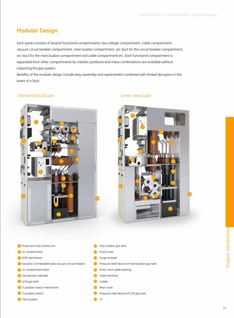
Modular Design
Each panel consists of several functional compartments: low voltage compartment, cable compartment,
vacuum circuit breaker compartment, main busbar compartment, arc duct for the circuit breaker compartment,
arc duct for the main busbar compartment and cable compartment etc. Each functional compartment is
separated from other compartments by metallic partitions and many combinations are available without
impacting the gas system.
Benefits of the modular design include easy assembly and replacement combined with limited disruption in the
event of a fault.
1421
5
6
3
12
20
8
10
119
7
4 19
15
16
13
17
18
1
2
3
5
6
8
12
1014
20
18
17
16
15
74
19
911
Protection and control unit
LV compartment
VCB mechanism
SecoVac-G Embedded pole vacuum circuit breaker
LV compartment door
Gas density indicator
VCB gas tank
3-position switch mechanism
3-position switch
Main busbar
1
2
3
4
5
6
7
8
9
10
Standard SecoCube Green SecoCube
11
12
13
14
15
16
17
18
19
20
Main busbar gas tank
Front cover
Surge arrester
Pressure relief device of main busbar gas tank
Inner-cone cable bushing
Cable terminal
Cables
Rear cover
Pressure relief device of VCB gas tank
CT
Prod
uct I
ntro
duct
ion
14
SecoCube 36kV Gas Insulated Medium Voltage Switchgear
Structure
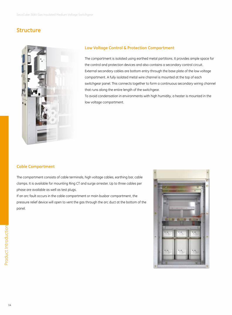
Low Voltage Control & Protection Compartment
Cable Compartment
The compartment is isolated using earthed metal partitions. It provides ample space for
the control and protection devices and also contains a secondary control circuit.
External secondary cables are bottom entry through the base plate of the low voltage
compartment. A fully isolated metal wire channel is mounted at the top of each
switchgear panel. This connects together to form a continuous secondary wiring channel
that runs along the entire length of the switchgear.
To avoid condensation in environments with high humidity, a heater is mounted in the
low voltage compartment.
The compartment consists of cable terminals, high voltage cables, earthing bar, cable
clamps. It is available for mounting Ring CT and surge arrester. Up to three cables per
phase are available as well as test plugs.
If an arc fault occurs in the cable compartment or main busbar compartment, the
pressure relief device will open to vent the gas through the arc duct at the bottom of the
panel.
Prod
uct I
ntro
duct
ion
15
SecoCube 36kV Gas Insulated Medium Voltage Switchgear
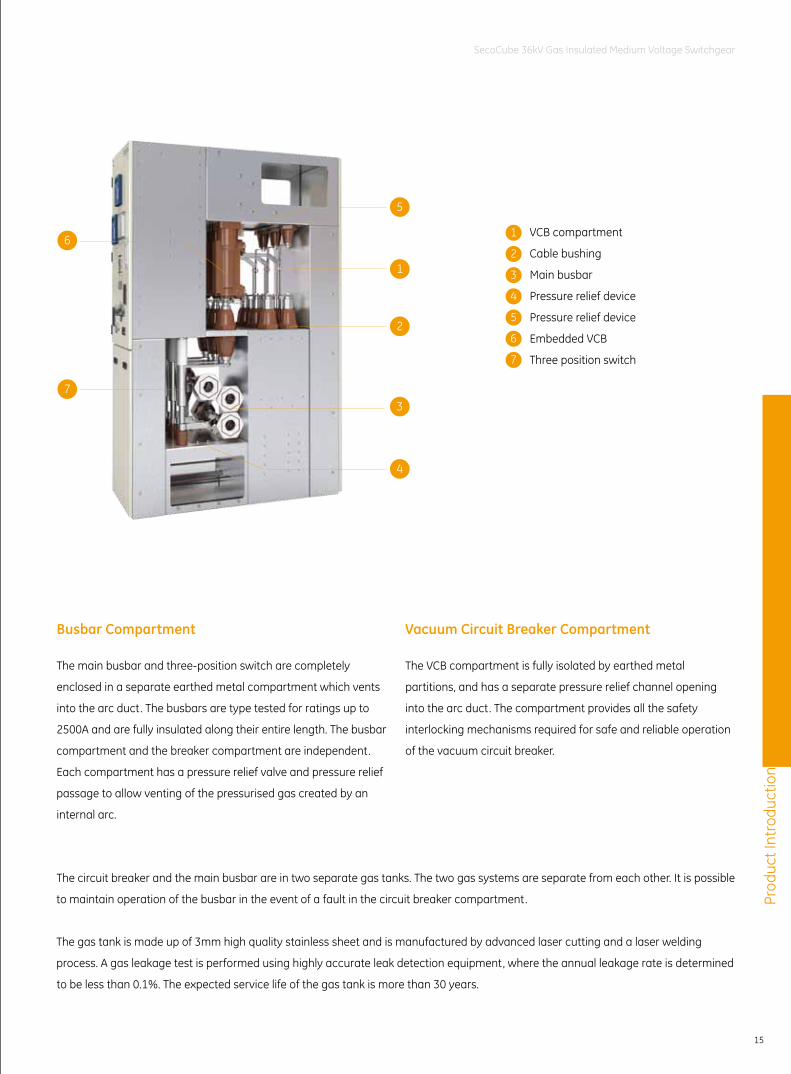
Vacuum Circuit Breaker CompartmentBusbar Compartment
The main busbar and three-position switch are completely
enclosed in a separate earthed metal compartment which vents
into the arc duct. The busbars are type tested for ratings up to
2500A and are fully insulated along their entire length. The busbar
compartment and the breaker compartment are independent.
Each compartment has a pressure relief valve and pressure relief
passage to allow venting of the pressurised gas created by an
internal arc.
The VCB compartment is fully isolated by earthed metal
partitions, and has a separate pressure relief channel opening
into the arc duct. The compartment provides all the safety
interlocking mechanisms required for safe and reliable operation
of the vacuum circuit breaker.
The circuit breaker and the main busbar are in two separate gas tanks. The two gas systems are separate from each other. It is possible
to maintain operation of the busbar in the event of a fault in the circuit breaker compartment.
The gas tank is made up of 3mm high quality stainless sheet and is manufactured by advanced laser cutting and a laser welding
process. A gas leakage test is performed using highly accurate leak detection equipment, where the annual leakage rate is determined
to be less than 0.1%. The expected service life of the gas tank is more than 30 years.
VCB compartment
Cable bushing
Main busbar
Pressure relief device
Pressure relief device
Embedded VCB
Three position switch
1
2
3
4
5
6
7
6
7
1
2
3
4
5
Prod
uct I
ntro
duct
ion
16
SecoCube 36kV Gas Insulated Medium Voltage Switchgear
Switchgear Front Panel
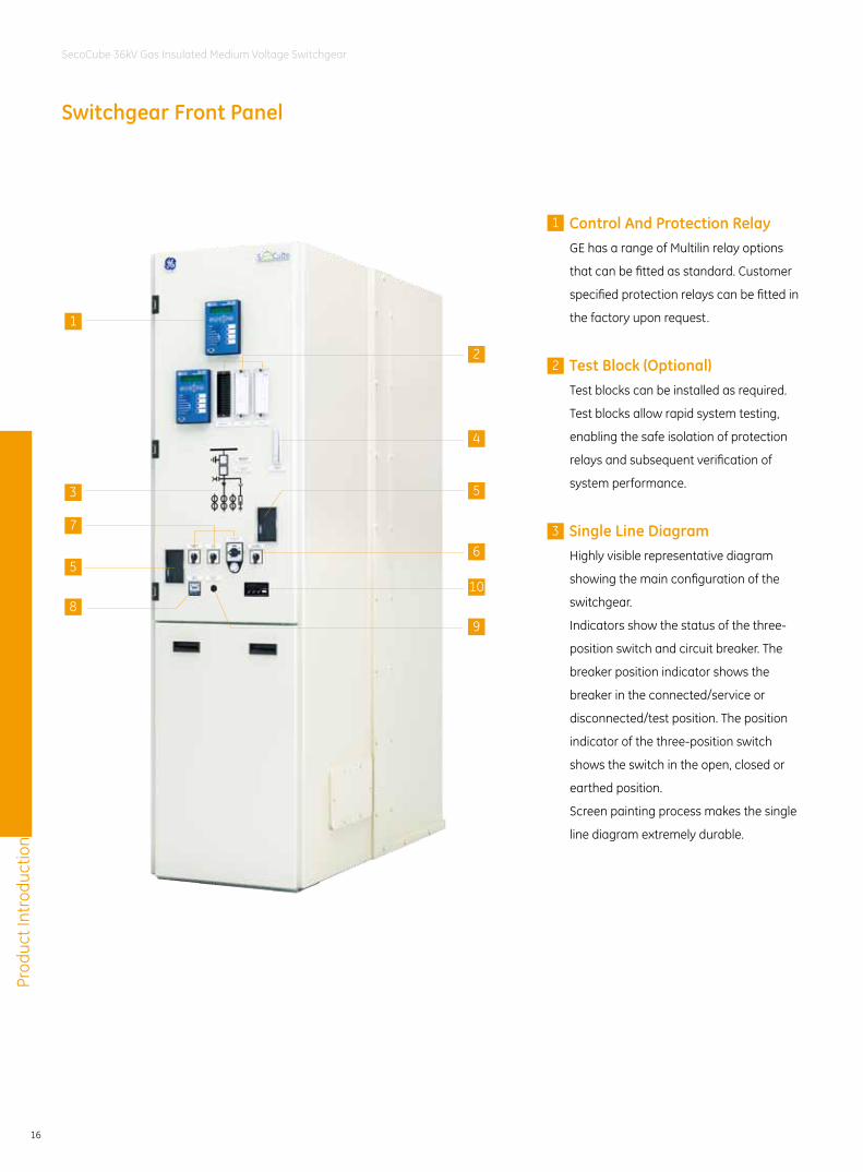
Control And Protection RelayGE has a range of Multilin relay options
that can be fitted as standard. Customer
specified protection relays can be fitted in
the factory upon request.
Test Block (Optional)Test blocks can be installed as required.
Test blocks allow rapid system testing,
enabling the safe isolation of protection
relays and subsequent verification of
system performance.
Single Line DiagramHighly visible representative diagram
showing the main configuration of the
switchgear.
Indicators show the status of the three-
position switch and circuit breaker. The
breaker position indicator shows the
breaker in the connected/service or
disconnected/test position. The position
indicator of the three-position switch
shows the switch in the open, closed or
earthed position.
Screen painting process makes the single
line diagram extremely durable.
1
1
3
7
5
8
4
5
6
9
10
22
3
Prod
uct I
ntro
duct
ion
17
SecoCube 36kV Gas Insulated Medium Voltage Switchgear
Mechanical LockAccess to the low voltage compartment door is controlled by a keyed lock. The
lower cover of the front panel is accessible only when the upper cover is open.
When the low voltage compartment door is closed, the switchgear can only be
modified using motorised operation.
Viewing windowsThe viewing windows allow viewing of the pressure indicator on the gas tank.
Local-Remote Selector SwitchOperator can choose to operate the circuit breaker and the three-position
disconnector locally or remotely via local-remote selector switch. Various control
means can be used such as protection relays, switches, PLCs.
Disconnector Switch/ Earth Switch/ Circuit Breaker SwitchFor motorized operation.
Heat MonitorWhen the ambient humidity reaches ≥ 60%RH ±5%, the heater switches on to
control the humidity and temperature inside the switchgear.
Trip Circuit HealthyThe device is to show the VCB is tripped by fault.
Voltage Presence Indicating SystemThe capacitive high voltage indicator works in conjunction with the integrated
sensor to detect the live condition of the feeder and the busbar. It also verifies the
safe isolation from the supply.
The capacitive high voltage indicator with interlock function can lock the
switchgear to prevent any dangerous operation or access when the equipment is
live.
Test sockets are available on the front panel for phase checking.
4
6
7
8
9
10
Function5
Prod
uct I
ntro
duct
ion
18
SecoCube 36kV Gas Insulated Medium Voltage Switchgear
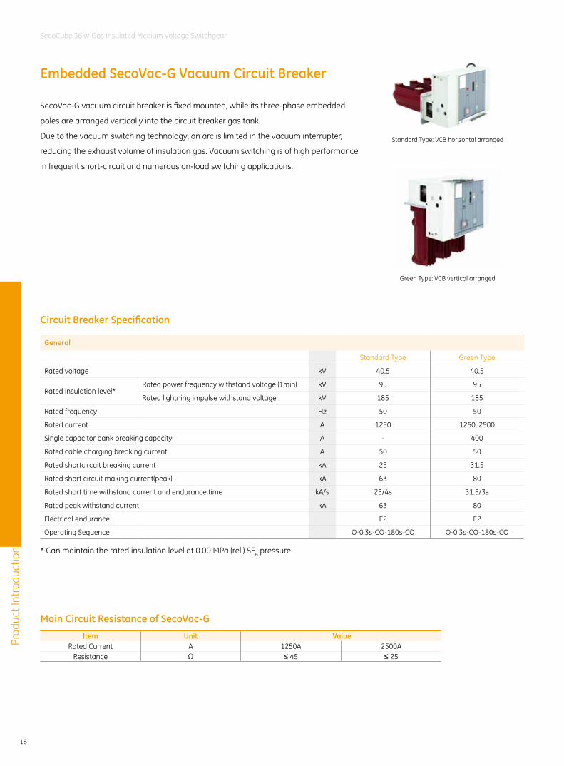
Embedded SecoVac-G Vacuum Circuit Breaker
SecoVac-G vacuum circuit breaker is fixed mounted, while its three-phase embedded
poles are arranged vertically into the circuit breaker gas tank.
Due to the vacuum switching technology, an arc is limited in the vacuum interrupter,
reducing the exhaust volume of insulation gas. Vacuum switching is of high performance
in frequent short-circuit and numerous on-load switching applications.
Circuit Breaker Specification
Main Circuit Resistance of SecoVac-G
General
Standard Type Green Type
Rated voltage kV 40.5 40.5
Rated insulation level*Rated power frequency withstand voltage (1min) kV 95 95
Rated lightning impulse withstand voltage kV 185 185
Rated frequency Hz 50 50
Rated current A 1250 1250, 2500
Single capacitor bank breaking capacity A - 400
Rated cable charging breaking current A 50 50
Rated shortcircuit breaking current kA 25 31.5
Rated short circuit making current(peak) kA 63 80
Rated short time withstand current and endurance time kA/s 25/4s 31.5/3s
Rated peak withstand current kA 63 80
Electrical endurance E2 E2
Operating Sequence O-0.3s-CO-180s-CO O-0.3s-CO-180s-CO
Item Unit ValueRated Current A 1250A 2500A
Resistance Ω ≤ 45 ≤ 25
* Can maintain the rated insulation level at 0.00 MPa (rel.) SF6 pressure.
Standard Type: VCB horizontal arranged
Green Type: VCB vertical arranged
Prod
uct I
ntro
duct
ion
19
SecoCube 36kV Gas Insulated Medium Voltage Switchgear
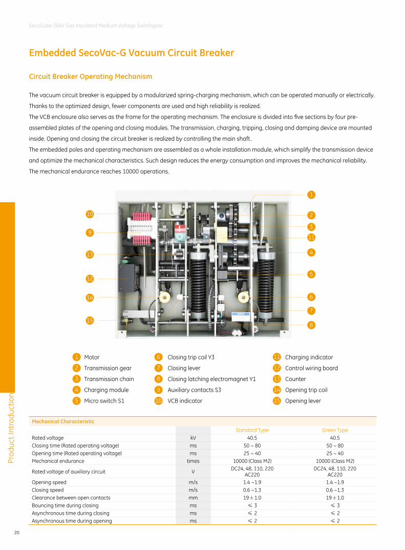
Close button
Open button
Counter
VCB indicator
1
2
3
4
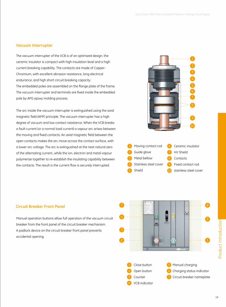
Moving contact rod
Guide glove
Metal bellow
Stainless steel cover
Shield
1
2
3
4
5
6
7
8
9
10
Ceramic insulator
HV Shield
Contacts
Fixed contact rod
stainless steel cover
1
2
3
4
5
67
8
9
10
5
6
7
Manual charging
Charging status indicator
Circuit breaker nameplate
Manual operation buttons allow full operation of the vacuum circuit
breaker from the front panel of the circuit breaker mechanism.
A padlock device on the circuit breaker front panel prevents
accidental opening.
Circuit Breaker Front Panel
Vacuum Interrupter
The vacuum interrupter of the VCB is of an optimized design, the
ceramic insulator is compact with high insulation level and a high
current breaking capability. The contacts are made of Copper-
Chromium, with excellent abrasion resistance, long electrical
endurance, and high short circuit breaking capacity.
The embedded poles are assembled on the flange plate of the frame.
The vacuum interrupter and terminals are fixed inside the embedded
pole by APG epoxy molding process.
The arc inside the vacuum interrupter is extinguished using the axial
magnetic field (AMF) principle. The vacuum interrupter has a high
degree of vacuum and low contact resistance. When the VCB breaks
a fault current (or a normal load current) a vapour arc arises between
the moving and fixed contacts. An axial magnetic field between the
open contacts makes the arc move across the contact surface, with
a lower arc voltage. The arc is extinguished at the next natural zero
of the alternating current, while the ion, electron and metal vapour
polymerize together to re-establish the insulating capability between
the contacts. The result is the current flow is securely interrupted.
7
3
2
4
6
5
1
Prod
uct I
ntro
duct
ion
20
SecoCube 36kV Gas Insulated Medium Voltage Switchgear
Circuit Breaker Operating Mechanism
The vacuum circuit breaker is equipped by a modularized spring-charging mechanism, which can be operated manually or electrically.
Thanks to the optimized design, fewer components are used and high reliability is realized.
The VCB enclosure also serves as the frame for the operating mechanism. The enclosure is divided into five sections by four pre-
assembled plates of the opening and closing modules. The transmission, charging, tripping, closing and damping device are mounted
inside. Opening and closing the circuit breaker is realized by controlling the main shaft.
The embedded poles and operating mechanism are assembled as a whole installation module, which simplify the transmission device
and optimize the mechanical characteristics. Such design reduces the energy consumption and improves the mechanical reliability.
The mechanical endurance reaches 10000 operations.
Mechanical Characteristic
Standard Type Green TypeRated voltage kV 40.5 40.5Closing time (Rated operating voltage) ms 50 ~ 80 50 ~ 80Opening time (Rated operating voltage) ms 25 ~ 40 25 ~ 40Mechanical endurance times 10000 (Class M2) 10000 (Class M2)
Rated voltage of auxiliary circuit V DC24, 48, 110, 220AC220
DC24, 48, 110, 220AC220
Opening speed m/s 1.4 ~1.9 1.4 ~1.9Closing speed m/s 0.6 ~1.3 0.6 ~1.3Clearance between open contacts mm 19±1.0 19±1.0Bouncing time during closing ms ≤ 3 ≤ 3Asynchronous time during closing ms ≤ 2 ≤ 2Asynchronous time during opening ms ≤ 2 ≤ 2
Embedded SecoVac-G Vacuum Circuit Breaker
1
2
3
11
5
6
7
815
14
12
13
9
10
Motor
Transmission gear
Transmission chain
Charging module
Micro switch S1
1 6 11
2 7 12
3 8 13
4 9 14
5 10 15
Closing trip coil Y3
Closing lever
Closing latching electromagnet Y1
Auxiliary contacts S3
VCB indicator
Charging indicator
Control wiring board
Counter
Opening trip coil
Opening lever
4
Prod
uct I
ntro
duct
ion
21
SecoCube 36kV Gas Insulated Medium Voltage Switchgear
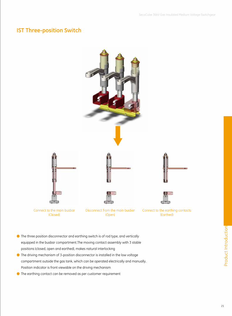
IST Three-position Switch
● The three position disconnector and earthing switch is of rod type, and vertically
equipped in the busbar compartment.The moving contact assembly with 3 stable
positions (closed, open and earthed), makes natural interlocking
● The driving mechanism of 3-position disconnector is installed in the low voltage
compartment outside the gas tank, which can be operated electrically and manually.
Position indicator is front viewable on the driving mechanism
● The earthing contact can be removed as per customer requirement
Connect to the main busbar(Closed)
Disconnect from the main busbar (Open)
Connect to the earthing contacts(Earthed)
Prod
uct I
ntro
duct
ion
22
SecoCube 36kV Gas Insulated Medium Voltage Switchgear
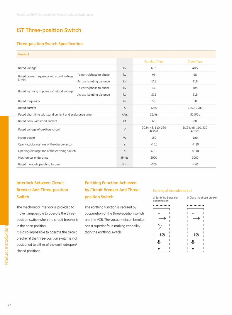
Three-position Switch Specification
General
Standard Type Green Type
Rated voltage kV 40.5 40.5
Rated power frequency withstand voltage (1min)
To earth/phase to phase kV 95 95
Across isolating distance kV 118 118
Rated lightning impulse withstand voltageTo earth/phase to phase kV 185 185
Across isolating distance kV 215 215
Rated frequency Hz 50 50
Rated current A 1250 1250, 2500
Rated short time withstand current and endurance time kA/s 25/4s 31.5/3s
Rated peak withstand current kA 63 80
Rated voltage of auxiliary circuit V DC24, 48, 110, 220AC220
DC24, 48, 110, 220AC220
Motor power W 180 180
Opening/closing time of the disconnector s ≤ 10 ≤ 10
Opening/closing time of the earthing switch s ≤ 10 ≤ 10
Mechanical endurance times 2000 2000
Rated manual operating torque Nm <20 <20
Interlock Between Circuit
Breaker And Three-position
Switch
Earthing Function Achieved
by Circuit Breaker And Three-
position Switch
The mechanical interlock is provided to
make it impossible to operate the three-
position switch when the circuit breaker is
in the open position.
It is also impossible to operate the circuit
breaker, if the three-position switch is not
positioned to either of the earthed/open/
closed positions.
The earthing function is realized by
cooperation of the three-position switch
and the VCB. The vacuum circuit breaker
has a superior fault making capability
than the earthing switch.
a) Earth the 3-position disconnector
Eathing of the cable circuit
b) Close the circuit breaker
IST Three-position Switch
Prod
uct I
ntro
duct
ion
23
SecoCube 36kV Gas Insulated Medium Voltage Switchgear
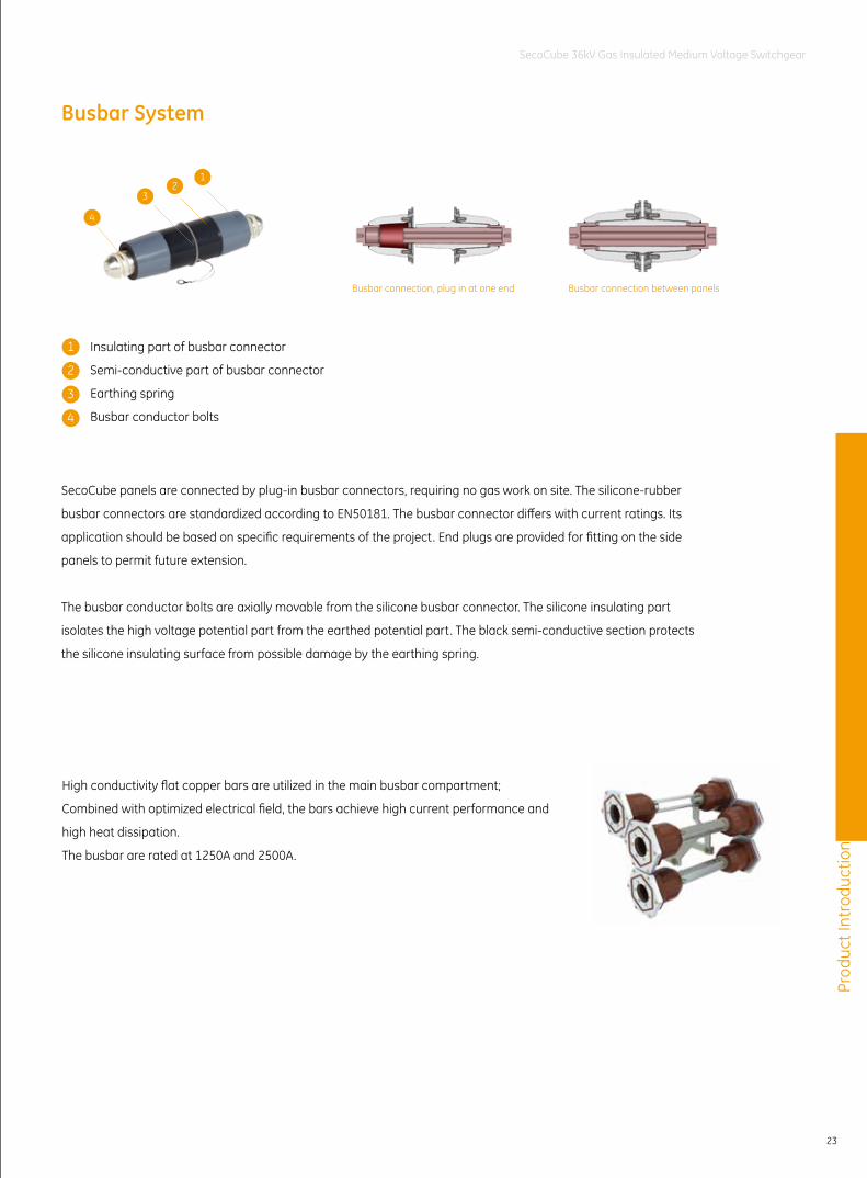
Busbar System
SecoCube panels are connected by plug-in busbar connectors, requiring no gas work on site. The silicone-rubber
busbar connectors are standardized according to EN50181. The busbar connector differs with current ratings. Its
application should be based on specific requirements of the project. End plugs are provided for fitting on the side
panels to permit future extension.
The busbar conductor bolts are axially movable from the silicone busbar connector. The silicone insulating part
isolates the high voltage potential part from the earthed potential part. The black semi-conductive section protects
the silicone insulating surface from possible damage by the earthing spring.
Insulating part of busbar connector
Semi-conductive part of busbar connector
Earthing spring
Busbar conductor bolts
12
4
3
Busbar connection, plug in at one end Busbar connection between panels
High conductivity flat copper bars are utilized in the main busbar compartment;
Combined with optimized electrical field, the bars achieve high current performance and
high heat dissipation.
The busbar are rated at 1250A and 2500A.
1
2
3
4
Prod
uct I
ntro
duct
ion
24
SecoCube 36kV Gas Insulated Medium Voltage Switchgear
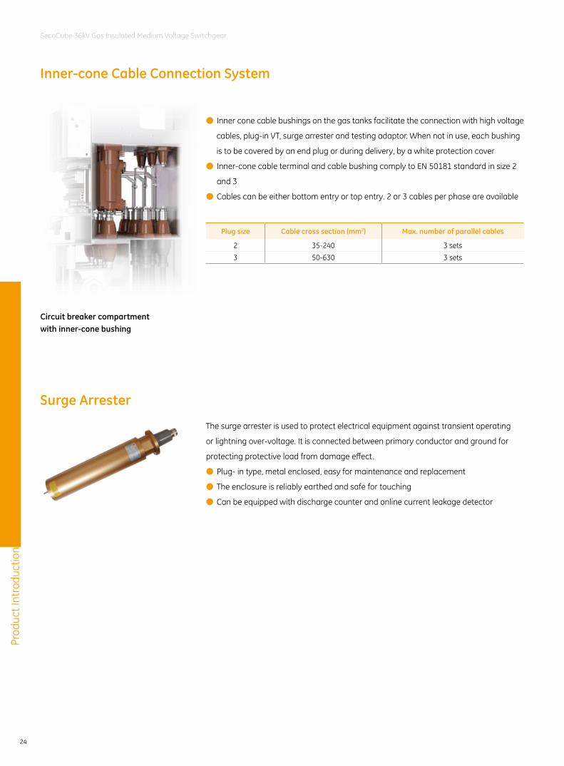
Inner-cone Cable Connection System
Surge Arrester
● Inner cone cable bushings on the gas tanks facilitate the connection with high voltage
cables, plug-in VT, surge arrester and testing adaptor. When not in use, each bushing
is to be covered by an end plug or during delivery, by a white protection cover
● Inner-cone cable terminal and cable bushing comply to EN 50181 standard in size 2
and 3
● Cables can be either bottom entry or top entry. 2 or 3 cables per phase are available
The surge arrester is used to protect electrical equipment against transient operating
or lightning over-voltage. It is connected between primary conductor and ground for
protecting protective load from damage effect.
● Plug- in type, metal enclosed, easy for maintenance and replacement
● The enclosure is reliably earthed and safe for touching
● Can be equipped with discharge counter and online current leakage detector
Plug size Cable cross section (mm2) Max. number of parallel cables
2 35-240 3 sets
3 50-630 3 sets
Circuit breaker compartment with inner-cone bushing
Prod
uct I
ntro
duct
ion
25
SecoCube 36kV Gas Insulated Medium Voltage Switchgear
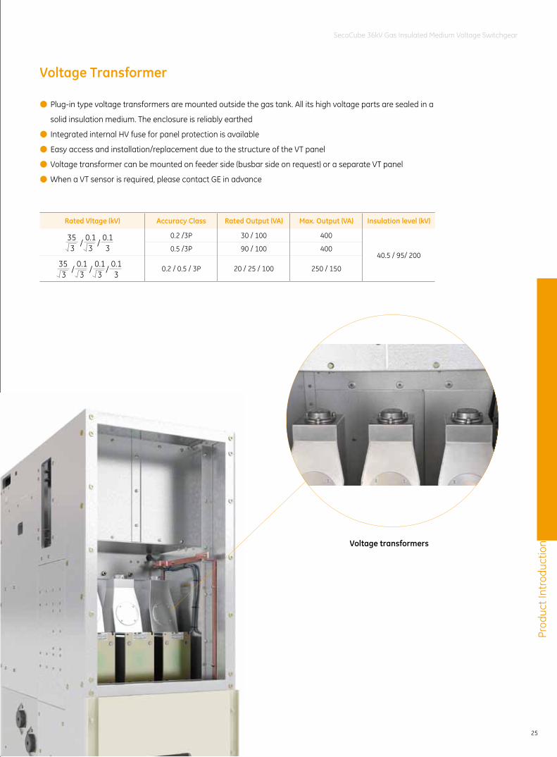
Voltage Transformer
● Plug-in type voltage transformers are mounted outside the gas tank. All its high voltage parts are sealed in a
solid insulation medium. The enclosure is reliably earthed
● Integrated internal HV fuse for panel protection is available
● Easy access and installation/replacement due to the structure of the VT panel
● Voltage transformer can be mounted on feeder side (busbar side on request) or a separate VT panel
● When a VT sensor is required, please contact GE in advance
Rated Vltage (kV) Accuracy Class Rated Output (VA) Max. Output (VA) Insulation level (kV)
0.2 /3P 30 / 100 400
40.5 / 95/ 2000.5 /3P 90 / 100 400
0.2 / 0.5 / 3P 20 / 25 / 100 250 / 150
/ /35 0.1 0.13 3 3
/ / /35 0.1 0.1 0.13 3 3 3
Voltage transformers
Prod
uct I
ntro
duct
ion
26
SecoCube 36kV Gas Insulated Medium Voltage Switchgear
Current Transformer
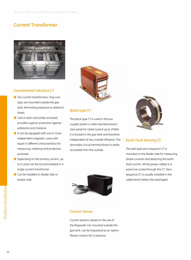
Conventional Inductive CT
● The current transformers, ring-core
type, are mounted outside the gas
tank, eliminating exposure to dielectric
stress
● Cast in resin and totally enclosed,
provides superior protection against
pollutants and moisture
● It can be equipped with one or more
independent magnetic cores with
equal or different characteristics for
measuring, metering and protection
purposes
● Depending on the primary current, up
to 5 cores can be accommodated in a
single current transformer
● Can be installed on feeder side or
busbar side
Earth Fault Sensing CT
The split type zero-sequence CT is
mounted on the feeder side for measuring
phase currents and detecting the earth
fault current. All the power cables in a
panel are routed through the CT. Zero-
sequence CT is usually installed in the
cable trench below the switchgear.
Current Sensor
Current sensors, based on the use of
the Rogowski coil, mounted outside the
gas tank, can be requested as an option.
Please contact GE in advance.
Block-type CT
The block type CT is used in the bus
coupler panel or cable riser/disconnect
riser panel for rated current up to 2500A.
It is located in the gas tank and therefore
independent of any outside influence. The
secondary circuit terminal board is easily
accessible from the outside.
Prod
uct I
ntro
duct
ion
27
SecoCube 36kV Gas Insulated Medium Voltage Switchgear
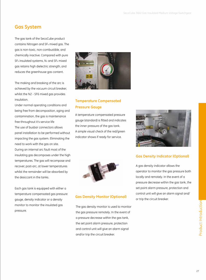
Gas System
Temperature Compensated
Pressure Gauge
Gas Density Monitor (Optional)
The gas tank of the SecoCube product
contains Nitrogen and SF6 mixed gas. The
gas is non-toxic, non-combustible, and
chemically inactive. Compared with pure
SF6 insulated systems, N2 and SF6 mixed
gas retains high dielectric strength, and
reduces the greenhouse gas content.
The making and breaking of the arc is
achieved by the vacuum circuit breaker,
whilst the N2 - SF6 mixed gas provides
insulation.
Under normal operating conditions and
being free from decomposition, aging and
contamination, the gas is maintenance
free throughout it's service life
The use of busbar connectors allows
panel installation to be performed without
impacting the gas system. Eliminating the
need to work with the gas on site.
During an internal arc fault most of the
insulating gas decomposes under the high
temperatures. The gas will recompose and
recover, post-arc, at lower temperatures
whilst the remainder will be absorbed by
the desiccant in the tanks.
Each gas tank is equipped with either a
temperature compensated gas pressure
gauge, density indicator or a density
monitor to monitor the insulated gas
pressure.
A temperature compensated pressure
gauge (standard) is fitted and indicates
the inner pressure of the gas tank.
A simple visual check of the red/green
indicator shows if ready for service.
The gas density monitor is used to monitor
the gas pressure remotely. In the event of
a pressure decrease within the gas tank,
the set point alarm pressure, protection
and control unit will give an alarm signal
and/or trip the circuit breaker.
Gas Density Indicator (Optional)
A gas density indicator allows the
operator to monitor the gas pressure both
locally and remotely. In the event of a
pressure decrease within the gas tank, the
set point alarm pressure, protection and
control unit will give an alarm signal and/
or trip the circuit breaker.
Prod
uct I
ntro
duct
ion
28
SecoCube 36kV Gas Insulated Medium Voltage Switchgear
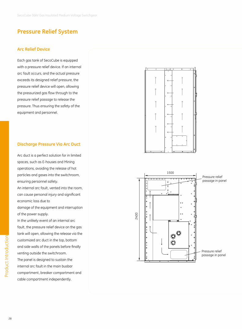
Pressure Relief System
Arc Relief Device
Discharge Pressure Via Arc Duct
Each gas tank of SecoCube is equipped
with a pressure relief device. If an internal
arc fault occurs, and the actual pressure
exceeds its designed relief pressure, the
pressure relief device will open, allowing
the pressurized gas flow through to the
pressure relief passage to release the
pressure. Thus ensuring the safety of the
equipment and personnel.
Arc duct is a perfect solution for in limited
spaces, such as E-houses and Mining
operations, avoiding the release of hot
particles and gases into the switchroom,
ensuring personnel safety.
An internal arc fault, vented into the room,
can cause personal injury and significant
economic loss due to
damage of the equipment and interruption
of the power supply.
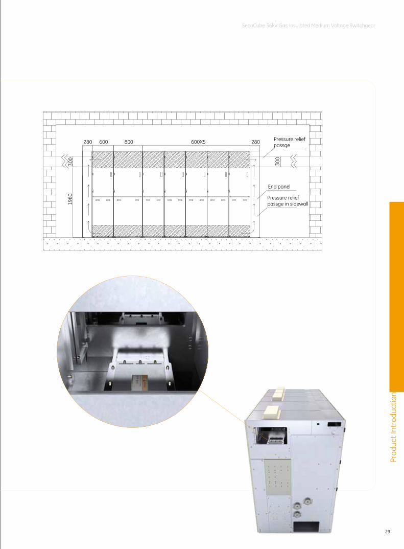
In the unlikely event of an internal arc
fault, the pressure relief device on the gas
tank will open, allowing the release via the
customized arc duct in the top, bottom
and side walls of the panels before finally
venting outside the switchroom.
The panel is designed to sustain the
internal arc fault in the main busbar
compartment, breaker compartment and
cable compartment independently.
1500
2400
Pressure reliefpassage in panel
Pressure reliefpassage in panel
Prod
uct I
ntro
duct
ion
29
SecoCube 36kV Gas Insulated Medium Voltage Switchgear
1960
300
280800 600X5600280
End panel
300
Pressure relief passge
Pressure relief passge in sidewall
Prod
uct I
ntro
duct
ion
30
SecoCube 36kV Gas Insulated Medium Voltage Switchgear
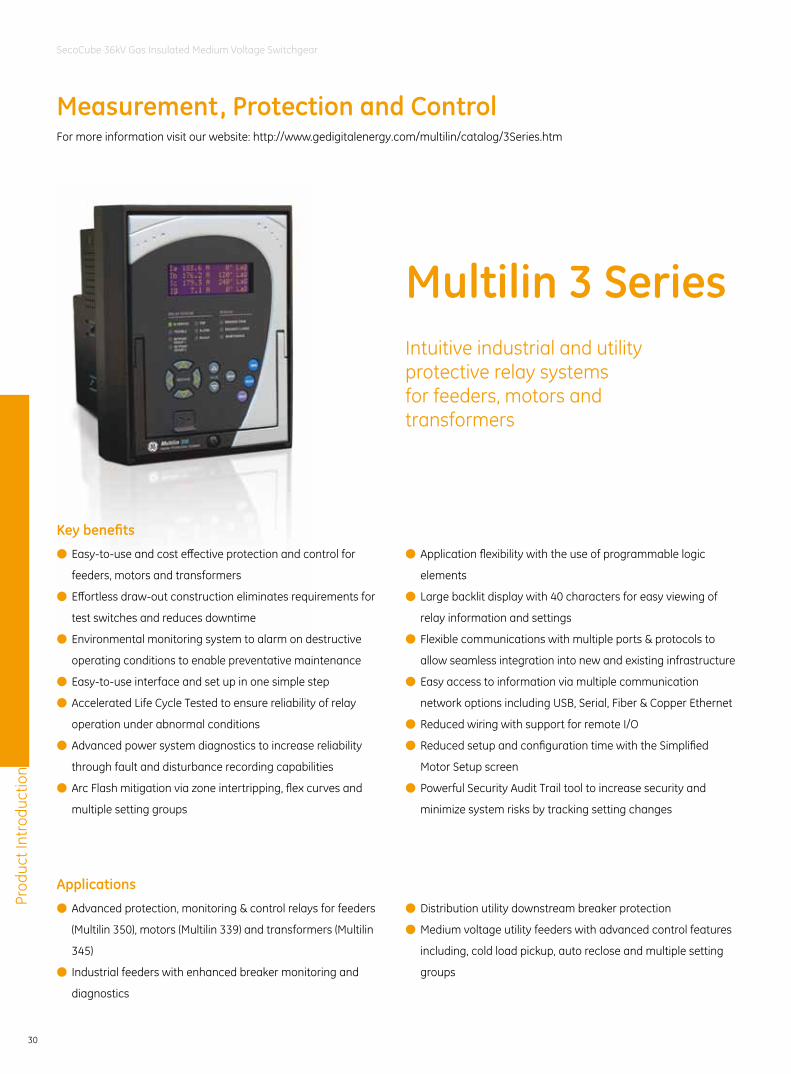
Intuitive industrial and utility protective relay systems for feeders, motors and transformers
Multilin 3 Series
Measurement, Protection and Control
Key benefits
Applications
● Easy-to-use and cost effective protection and control for
feeders, motors and transformers
● Effortless draw-out construction eliminates requirements for
test switches and reduces downtime
● Environmental monitoring system to alarm on destructive
operating conditions to enable preventative maintenance
● Easy-to-use interface and set up in one simple step
● Accelerated Life Cycle Tested to ensure reliability of relay
operation under abnormal conditions
● Advanced power system diagnostics to increase reliability
through fault and disturbance recording capabilities
● Arc Flash mitigation via zone intertripping, flex curves and
multiple setting groups
● Advanced protection, monitoring & control relays for feeders
(Multilin 350), motors (Multilin 339) and transformers (Multilin
345)
● Industrial feeders with enhanced breaker monitoring and
diagnostics
● Application flexibility with the use of programmable logic
elements
● Large backlit display with 40 characters for easy viewing of
relay information and settings
● Flexible communications with multiple ports & protocols to
allow seamless integration into new and existing infrastructure
● Easy access to information via multiple communication
network options including USB, Serial, Fiber & Copper Ethernet
● Reduced wiring with support for remote I/O
● Reduced setup and configuration time with the Simplified
Motor Setup screen
● Powerful Security Audit Trail tool to increase security and
minimize system risks by tracking setting changes
● Distribution utility downstream breaker protection
● Medium voltage utility feeders with advanced control features
including, cold load pickup, auto reclose and multiple setting
groups
For more information visit our website: http://www.gedigitalenergy.com/multilin/catalog/3Series.htm
Prod
uct I
ntro
duct
ion
31
SecoCube 36kV Gas Insulated Medium Voltage Switchgear
Features
Metering & monitoring
● Event Recorder: 256 events with 1ms
time stamping
● Oscillography with 32 samples per
cycle and digital states
● IRIG-B clock synchronization
● Relay & Asset Health Diagnostics
● Security audit trail
Protection & control
(for Multilin 350 Feeder Protection System)
● Phase, neutral and ground TOC and IOC
● Undervoltage, overvoltage, frequency
● Neutral/ground directional
● Negative sequence overcurrent
● ANSI, IAC, IEC, flex curves
● Cable Thermal Model protection
● Breaker failure
● Cold load pick-up
● Four-shot auto reclose
● 8 digital inputs, 7 contact outputs
● Two setting groups
User interface and programming
● 4x20 character LCD display
● Control panel with 12 LED indicators
● Front USB and rear serial, Ethernet and
Fiber ports
● Multiple protocols - IEC 61850 & 61850
GOOSE, ModBus ™ RTU, ModBus ™
TCP/IP, DNP 3.0, IEC 60870-5-104, IEC
60870-5-103
EnerVista ™ software
● An industry-leading suite of software
tools that simplifies every aspect of
working with Multilin devices
● Document and software archiving
toolset to ensure reference material
and device utilities are up-to-date
Overview
The Multilin 3 Series of protection relays
are highly functional, economical
protection relays for feeders, motors and
transformers. By providing an economical
system for protection, control, monitoring
and metering, and with both local and
remote user interfaces in one assembly,
the Multilin 3 Series relays effectively
eliminate the need for expensive discrete
components.
The Multilin 3 Series provides detailed
diagnostic information allowing users to
troubleshoot and minimize downtime.
Detailed diagnostics are provided via the
256 1ms time stamped event recorder
and the 192 cycle Oscillography report
sampled at 32 samples per cycle.
The robust Multilin 3 Series streamlines
user work flow processes and simplifies
engineering tasks such as configuration,
wiring, testing, commissioning, and
maintenance. This cost-effective relay
also offers enhanced features such as
diagnostics, preventative maintenance,
device health reports and advanced
security features.
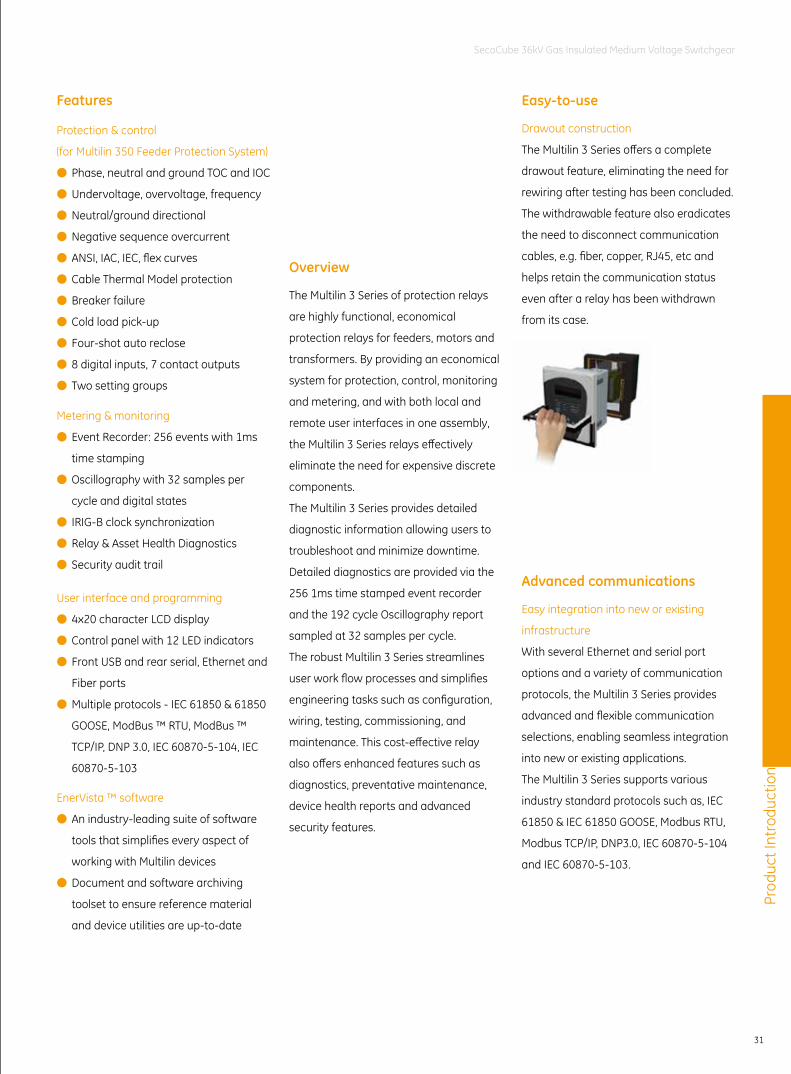
Easy-to-use
Drawout construction
The Multilin 3 Series offers a complete
drawout feature, eliminating the need for
rewiring after testing has been concluded.
The withdrawable feature also eradicates
the need to disconnect communication
cables, e.g. fiber, copper, RJ45, etc and
helps retain the communication status
even after a relay has been withdrawn
from its case.
Advanced communications
Easy integration into new or existing
infrastructure
With several Ethernet and serial port
options and a variety of communication
protocols, the Multilin 3 Series provides
advanced and flexible communication
selections, enabling seamless integration
into new or existing applications.
The Multilin 3 Series supports various
industry standard protocols such as, IEC
61850 & IEC 61850 GOOSE, Modbus RTU,
Modbus TCP/IP, DNP3.0, IEC 60870-5-104
and IEC 60870-5-103.
Prod
uct I
ntro
duct
ion
32
SecoCube 36kV Gas Insulated Medium Voltage Switchgear
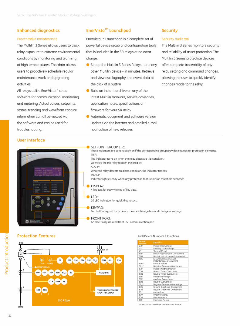
350 RELAY
TRIP
BUS
LOAD
3
1
52
CLOSE
50G/51G
50P 50N
79
50G 51G
2 2
2 1
METERING
TRANSIENT RECORDEREVENT RECORDER
51N51P 50_2
1 1 1
49
1
1
27P 59P 27X 59X 59_2 59N 81U 81O
CLP 50BF 79
1 1 1 1 1 1 2 2
MONITORING
BUS VT
Device Number Function27P Phase Undervoltage27X Auxiliary Undervoltage49 Thermal Model50P Phase Instantaneous Overcurrent50N Neutral Instantaneous Overcurrent50G Ground/Sensitive Ground
Instantaneous Overcurrent50BF Breaker Failure50_2 Negative Sequence Overcurrent51P Phase Timed Overcurrent51G Ground Timed Overcurrent51N Neutral Timed Overcurrent59P Phase Overvoltage59X Auxiliary Overvoltage59N Neutral Overvoltage59_2 Negative Sequence Overvoltage67G Ground Directional Overcurrent67N Neutral Directional Overcurrent79 Autoreclose81U Underfrequency81O OverfrequencyCLP Cold Load Pickup
ANSI Device Numbers & Functions
Latched Lockout available as a standard feature
Preventative maintenance
The Multilin 3 Series allows users to track
relay exposure to extreme environmental
conditions by monitoring and alarming
at high temperatures. This data allows
users to proactively schedule regular
maintenance work and upgrading
activities.
All relays utilize EnerVistaTM setup
software for communication, monitoring
and metering. Actual values, setpoints,
status, trending and waveform capture
information can all be viewed via
the software and can be used for
troubleshooting.
SecurityEnerVistaTM LaunchpadEnhanced diagnostics
User Interface
Protection Features
Security audit trail
The Multilin 3 Series monitors security
and reliability of asset protection. The
Multilin 3 Series protection devices
offer complete traceability of any
relay setting and command changes,
allowing the user to quickly identify
changes made to the relay.
EnerVista ™ Launchpad is a complete set of
powerful device setup and configuration tools
that is included in the SR relays at no extra
charge.
● Set up the Multilin 3 Series Relays - and any
other Multilin device - in minutes. Retrieve
and view oscillography and event data at
the click of a button
● Build an instant archive on any of the
latest Multilin manuals, service advisories,
application notes, specifications or
firmware for your SR Relay
● Automatic document and software version
updates via the internet and detailed e-mail
notification of new releases
● SETPOINT GROUP 1, 2:These indicators are continuously on if the corresponding group provides settings for protection elements.TRIP:The indicator turns on when the relay detects a trip condition.Operates the trip relay to open the breaker.ALARM:While the relay detects an alarm condition, the indicator flashes.PICKUP:Indicator lights steady when any protection feature pickup threshold exceeded.
● DISPLAY:4 line text for easy viewing of key data.
● LEDs:10 LED indicators for quick diagnostics.
● KEYPAD:Ten button keypad for access to device interrogation and change of settings.
● FRONT PORT:An electrically isolated front USB communication port.
Prod
uct I
ntro
duct
ion
33
SecoCube 36kV Gas Insulated Medium Voltage Switchgear
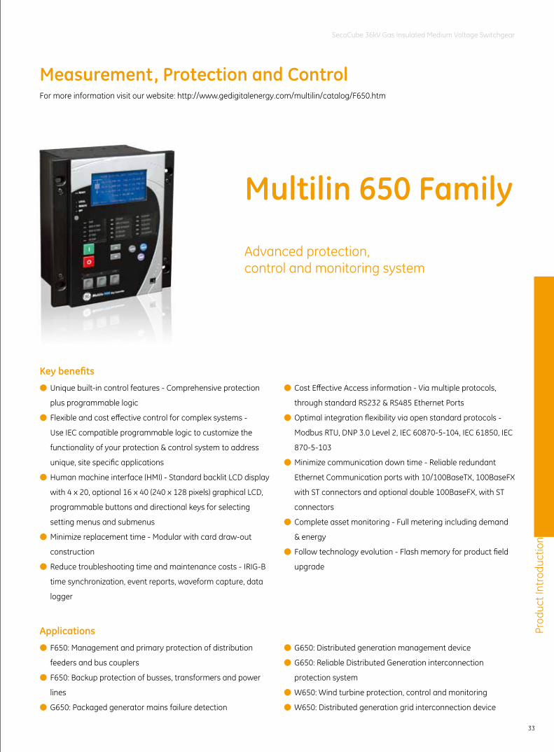
Advanced protection,control and monitoring system
Measurement, Protection and Control
Key benefits ● Unique built-in control features - Comprehensive protection
plus programmable logic
● Flexible and cost effective control for complex systems -
Use IEC compatible programmable logic to customize the
functionality of your protection & control system to address
unique, site specific applications
● Human machine interface (HMI) - Standard backlit LCD display
with 4 x 20, optional 16 x 40 (240 x 128 pixels) graphical LCD,
programmable buttons and directional keys for selecting
setting menus and submenus
● Minimize replacement time - Modular with card draw-out
construction
● Reduce troubleshooting time and maintenance costs - IRIG-B
time synchronization, event reports, waveform capture, data
logger
● Cost Effective Access information - Via multiple protocols,
through standard RS232 & RS485 Ethernet Ports
● Optimal integration flexibility via open standard protocols -
Modbus RTU, DNP 3.0 Level 2, IEC 60870-5-104, IEC 61850, IEC
870-5-103
● Minimize communication down time - Reliable redundant
Ethernet Communication ports with 10/100BaseTX, 100BaseFX
with ST connectors and optional double 100BaseFX, with ST
connectors
● Complete asset monitoring - Full metering including demand
& energy
● Follow technology evolution - Flash memory for product field
upgrade
Applications ● F650: Management and primary protection of distribution
feeders and bus couplers
● F650: Backup protection of busses, transformers and power
lines
● G650: Packaged generator mains failure detection
● G650: Distributed generation management device
● G650: Reliable Distributed Generation interconnection
protection system
● W650: Wind turbine protection, control and monitoring
● W650: Distributed generation grid interconnection device
Multilin 650 Family
For more information visit our website: http://www.gedigitalenergy.com/multilin/catalog/F650.htm
Prod
uct I
ntro
duct
ion
34
SecoCube 36kV Gas Insulated Medium Voltage Switchgear
Features
Overview
Protection and control
● Up to 32 Programmable digital inputs
● Up to 16 digital outputs
● Trip Circuit Supervision
● Redundant power supply option
● Configurable PLC logic according to IEC 61131-3
● Fully configurable graphic display HMI interface
● Alarms panel
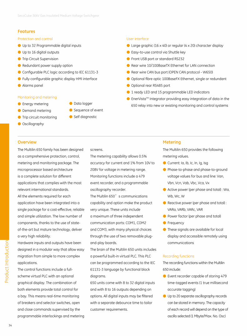
The Multilin 650 family has been designed
as a comprehensive protection, control,
metering and monitoring package. The
microprocessor based architecture
is a complete solution for different
applications that complies with the most
relevant international standards.
All the elements required for each
application have been integrated into a
single package for a cost-effective, reliable
and simple utilization. The low number of
components, thanks to the use of state-
of-the-art but mature technology, deliver
a very high reliability.
Hardware inputs and outputs have been
designed in a modular way that allow easy
migration from simple to more complex
applications.
The control functions include a full-
scheme virtual PLC with an optional
graphical display. The combination of
both elements provide total control for
a bay. This means real-time monitoring
of breakers and selector switches, open
and close commands supervised by the
programmable interlockings and metering
User interface
● Large graphic (16 x 40) or regular (4 x 20) character display
● Easy-to-use control via Shuttle key
● Front USB port or standard RS232
● Rear wire 10/100BaseTX Ethernet for LAN connection
● Rear wire CAN bus port (OPEN CAN protocol - W650)
● Optional fibre optic 100BaseFX Ethernet, single or redundant
● Optional rear RS485 port
● 1 ready LED and 15 programmable LED indicators
● EnerVistaTM Integrator providing easy integration of data in the
650 relay into new or existing monitoring and control systems
Monitoring and metering
● Energy metering
● Demand metering
● Trip circuit monitoring
● Oscillography
screens.
The metering capability allows 0.5%
accuracy for current and 1% from 10V to
208V for voltage in metering range.
Monitoring functions include a 479
event recorder, and a programmable
oscillography recorder.
The Multilin 650’s communications
capability and option make the product
very unique. These units include
a maximum of three independent
communication ports: COM1, COM2
and COM3, with many physical choices
through the use of two removable plug-
and-play boards.
The brain of the Multilin 650 units includes
a powerful built-in virtual PLC. This PLC
can be programmed according to the IEC
61131-3 language by functional block
diagrams.
650 units come with 8 to 32 digital inputs
and with 8 to 16 outputs depending on
options. All digital inputs may be filtered
with a separate debounce time to tailor
customer requirements.
● Data logger
● Sequence of event
● Self diagnostic
Metering
The Multilin 650 provides the following
metering values.
● Current: Ia, Ib, Ic, In, Ig, Isg
● Phase-to-phase and phase-to-ground
voltage values for bus and line: Van,
Vbn, Vcn, Vab, Vbc, Vca, Vx
● Active power (per phase and total) : Wa,
Wb, Wc, W
● Reactive power (per phase and total) :
VARa, VARb, VARc, VAR
● Power factor (per phase and total)
● Frequency
● These signals are available for local
display and accessible remotely using
communications
Recording functions
The recording functions within the Multilin
650 include:
● Event recorder capable of storing 479
time-tagged events (1 true millisecond
accurate tagging)
● Up to 20 separate oscillography records
can be stored in memory. The capacity
of each record will depend on the type of
oscillo selected (1 Mbyte/Max. No. Osc)
Prod
uct I
ntro
duct
ion
35
SecoCube 36kV Gas Insulated Medium Voltage Switchgear
EN F650 BLOCK F.CDR
22
F650 Digital Bay Controller
RR
METERING
52
3
3
1
1
1
79
51G 67G
67SG
67P
50SG 51SG 50IG
50N 51N 67N59X
27X
59NH
25
3V_0
51PL/V51PH/V
MonitoringCLOSE TRIP
50G
1
50BF1
493
50PH3
50PL3
463
483
32FP3
323
32N3 3
BROKENCONDUCTOR
33 3 3 3 3
3
3
1
3
3
33
593
VTFF1
273
473
3
81O3
81R3
81U3
3 33
59NL3
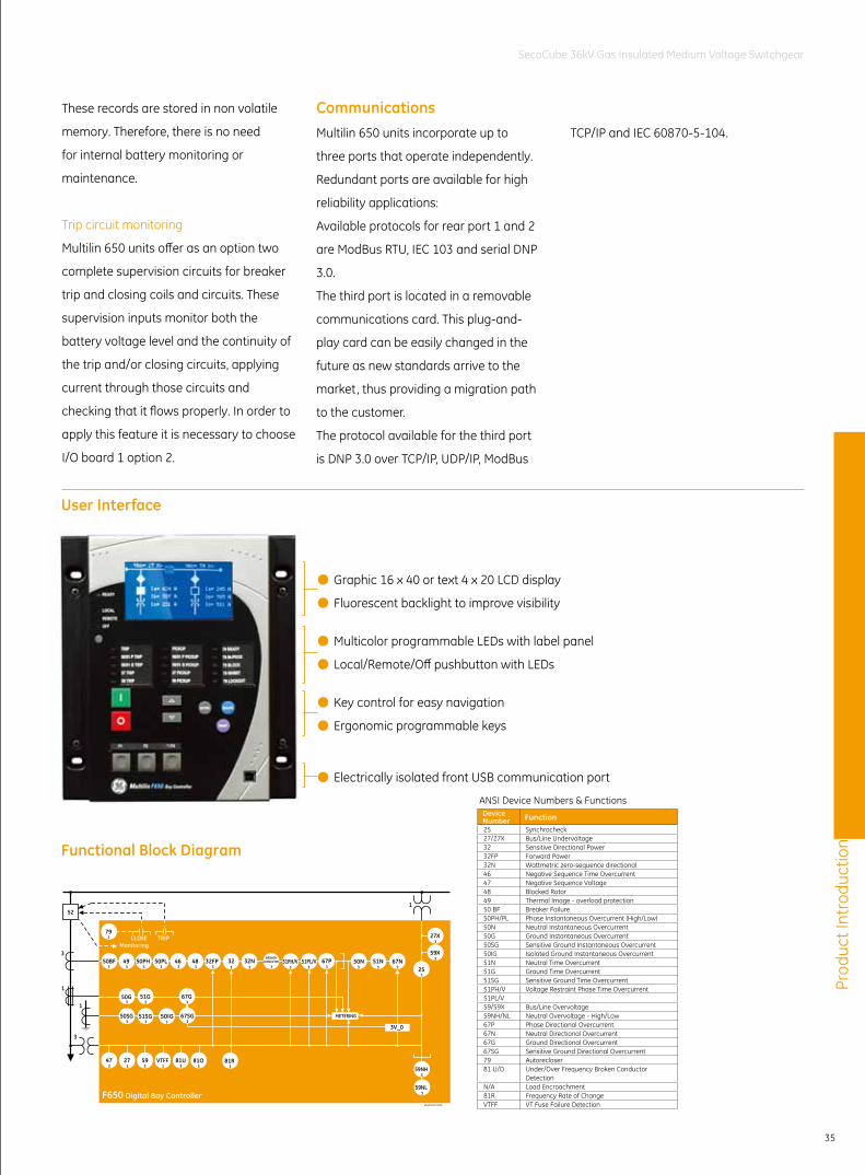
Device Number Function25 Synchrocheck27/27X Bus/Line Undervoltage32 Sensitive Directional Power32FP Forward Power32N Wattmetric zero-sequence directional46 Negative Sequence Time Overcurrent47 Negative Sequence Voltage48 Blocked Rotor49 Thermal Image - overload protection50 BF Breaker Failure50PH/PL Phase Instantaneous Overcurrent (High/Low)50N Neutral Instantaneous Overcurrent50G Ground Instantaneous Overcurrent50SG Sensitive Ground Instantaneous Overcurrent50IG Isolated Ground Instantaneous Overcurrent51N Neutral Time Overcurrent51G Ground Time Overcurrent51SG Sensitive Ground Time Overcurrent51PH/V Voltage Restraint Phase Time Overcurrent51PL/V59/59X Bus/Line Overvoltage59NH/NL Neutral Overvoltage - High/Low67P Phase Directional Overcurrent67N Neutral Directional Overcurrent67G Ground Directional Overcurrent67SG Sensitive Ground Directional Overcurrent79 Autorecloser81 U/O Under/Over Frequency Broken Conductor
DetectionN/A Load Encroachment81R Frequency Rate of ChangeVTFF VT Fuse Failure Detection
ANSI Device Numbers & Functions
These records are stored in non volatile
memory. Therefore, there is no need
for internal battery monitoring or
maintenance.
Trip circuit monitoring
Multilin 650 units offer as an option two
complete supervision circuits for breaker
trip and closing coils and circuits. These
supervision inputs monitor both the
battery voltage level and the continuity of
the trip and/or closing circuits, applying
current through those circuits and
checking that it flows properly. In order to
apply this feature it is necessary to choose
I/O board 1 option 2.
CommunicationsMultilin 650 units incorporate up to
three ports that operate independently.
Redundant ports are available for high
reliability applications:
Available protocols for rear port 1 and 2
are ModBus RTU, IEC 103 and serial DNP
3.0.
The third port is located in a removable
communications card. This plug-and-
play card can be easily changed in the
future as new standards arrive to the
market, thus providing a migration path
to the customer.
The protocol available for the third port
is DNP 3.0 over TCP/IP, UDP/IP, ModBus
TCP/IP and IEC 60870-5-104.
● Graphic 16 x 40 or text 4 x 20 LCD display
● Fluorescent backlight to improve visibility
● Multicolor programmable LEDs with label panel
● Local/Remote/Off pushbutton with LEDs
● Key control for easy navigation
● Ergonomic programmable keys
● Electrically isolated front USB communication port
User Interface
Functional Block Diagram
Prod
uct I
ntro
duct
ion
36
SecoCube 36kV Gas Insulated Medium Voltage Switchgear
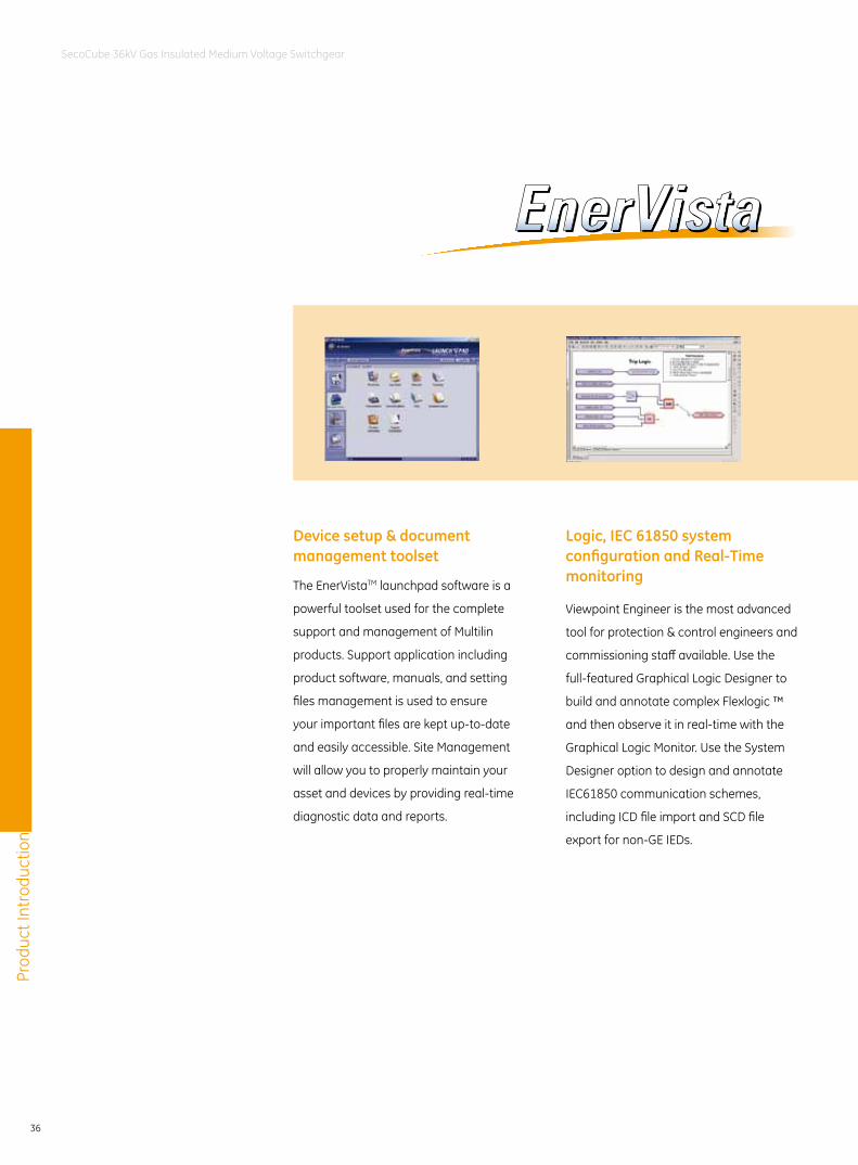
The EnerVistaTM launchpad software is a
powerful toolset used for the complete
support and management of Multilin
products. Support application including
product software, manuals, and setting
files management is used to ensure
your important files are kept up-to-date
and easily accessible. Site Management
will allow you to properly maintain your
asset and devices by providing real-time
diagnostic data and reports.
Viewpoint Engineer is the most advanced
tool for protection & control engineers and
commissioning staff available. Use the
full-featured Graphical Logic Designer to
build and annotate complex Flexlogic ™
and then observe it in real-time with the
Graphical Logic Monitor. Use the System
Designer option to design and annotate
IEC61850 communication schemes,
including ICD file import and SCD file
export for non-GE IEDs.
Device setup & document management toolset
Logic, IEC 61850 system configuration and Real-Time monitoring
Prod
uct I
ntro
duct
ion
37
SecoCube 36kV Gas Insulated Medium Voltage Switchgear
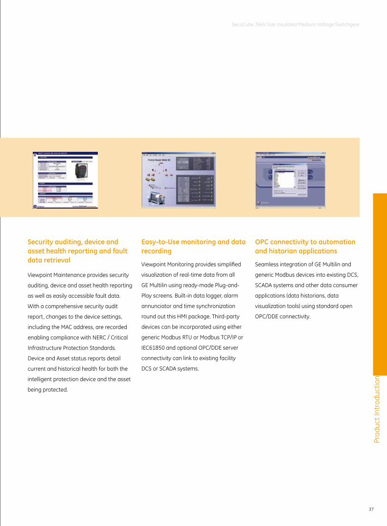
Viewpoint Maintenance provides security
auditing, device and asset health reporting
as well as easily accessible fault data.
With a comprehensive security audit
report, changes to the device settings,
including the MAC address, are recorded
enabling compliance with NERC / Critical
Infrastructure Protection Standards.
Device and Asset status reports detail
current and historical health for both the
intelligent protection device and the asset
being protected.
Viewpoint Monitoring provides simplified
visualization of real-time data from all
GE Multilin using ready-made Plug-and-
Play screens. Built-in data logger, alarm
annunciator and time synchronization
round out this HMI package. Third-party
devices can be incorporated using either
generic Modbus RTU or Modbus TCP/IP or
IEC61850 and optional OPC/DDE server
connectivity can link to existing facility
DCS or SCADA systems.
Seamless integration of GE Multilin and
generic Modbus devices into existing DCS,
SCADA systems and other data consumer
applications (data historians, data
visualization tools) using standard open
OPC/DDE connectivity.
Security auditing, device and asset health reporting and fault data retrieval
Easy-to-Use monitoring and data recording
OPC connectivity to automation and historian applications
Prod
uct I
ntro
duct
ion
38
SecoCube 36kV Gas Insulated Medium Voltage Switchgear
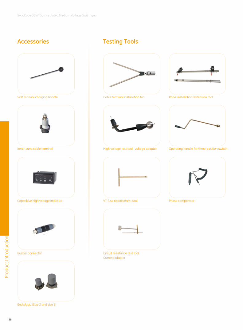
Accessories Testing Tools
Capacitive high voltage indicator
Inner-cone cable terminal
Busbar connector
End plugs (Size 2 and size 3)
Operating handle for three-position switchHigh voltage test tool: voltage adaptor
Cable terminal installation tool Panel installation/extension toolVCB manual charging handle
Phase comparator
Circuit resistance test tool: Current adapter
VT fuse replacement tool
39
SecoCube 36kV Gas Insulated Medium Voltage Switchgear
Typi
cal s
olut
ionTypical solution
Standard SecoCube Typical Panels . . . . . . . . . . . . . . . . . . . . . . . . . . . .40
Green SecoCube Typical Panels . . . . . . . . . . . . . . . . . . . . . . . . . . . . . . .41
Typical Schemes . . . . . . . . . . . . . . . . . . . . . . . . . . . . . . . . . . . . . . . . . . . . .43
40
SecoCube 36kV Gas Insulated Medium Voltage Switchgear
Typi
cal s
olut
ion
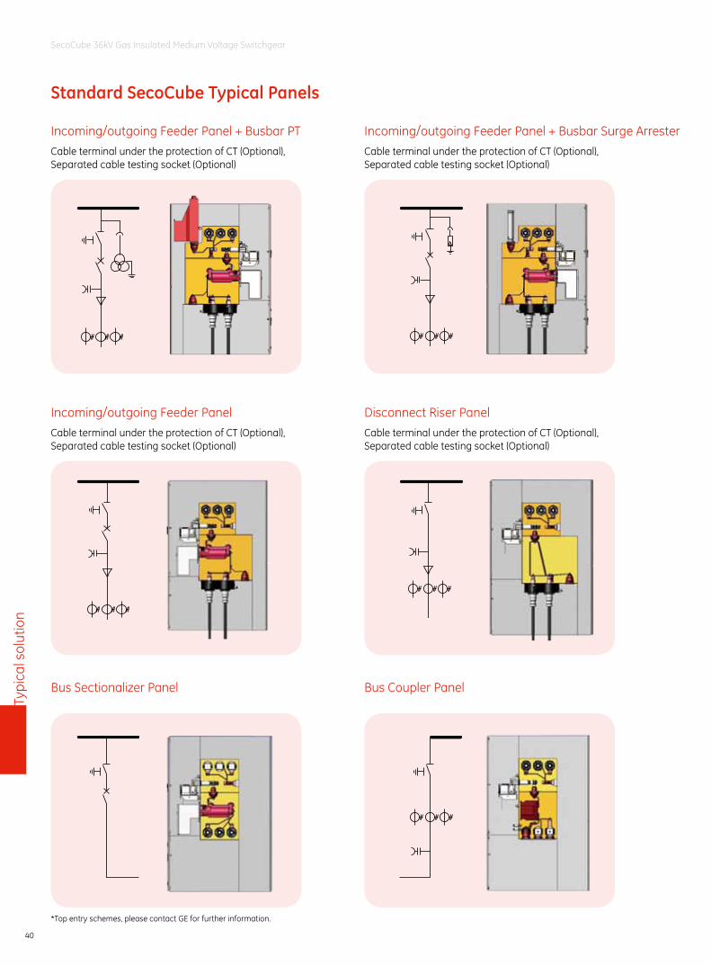
Standard SecoCube Typical Panels
Incoming/outgoing Feeder Panel + Busbar PTCable terminal under the protection of CT (Optional),Separated cable testing socket (Optional)
Incoming/outgoing Feeder Panel + Busbar Surge ArresterCable terminal under the protection of CT (Optional),Separated cable testing socket (Optional)
Incoming/outgoing Feeder PanelCable terminal under the protection of CT (Optional),Separated cable testing socket (Optional)
Disconnect Riser PanelCable terminal under the protection of CT (Optional),Separated cable testing socket (Optional)
Bus Coupler PanelBus Sectionalizer Panel
*Top entry schemes, please contact GE for further information.
41
SecoCube 36kV Gas Insulated Medium Voltage Switchgear
Typi
cal s
olut
ion
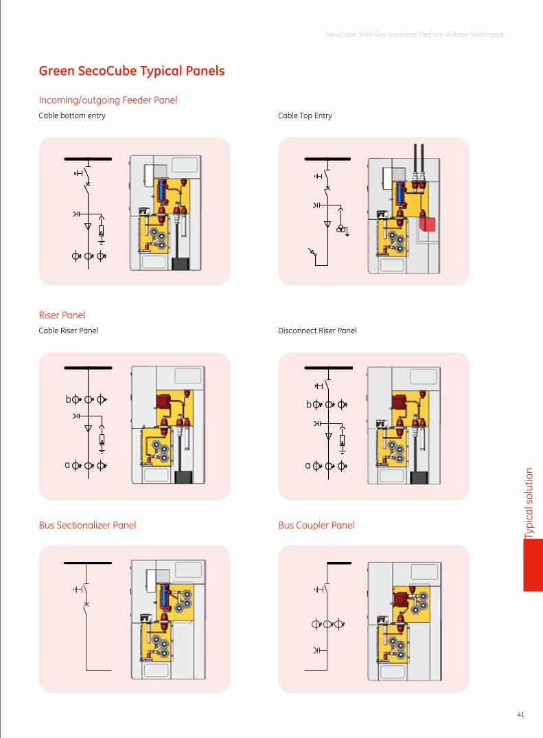
Green SecoCube Typical Panels
Incoming/outgoing Feeder PanelCable bottom entry
Riser PanelCable Riser Panel
Bus Sectionalizer Panel Bus Coupler Panel
Disconnect Riser Panel
Cable Top Entry
a
b b
a
42
SecoCube 36kV Gas Insulated Medium Voltage Switchgear
Typi
cal s
olut
ion
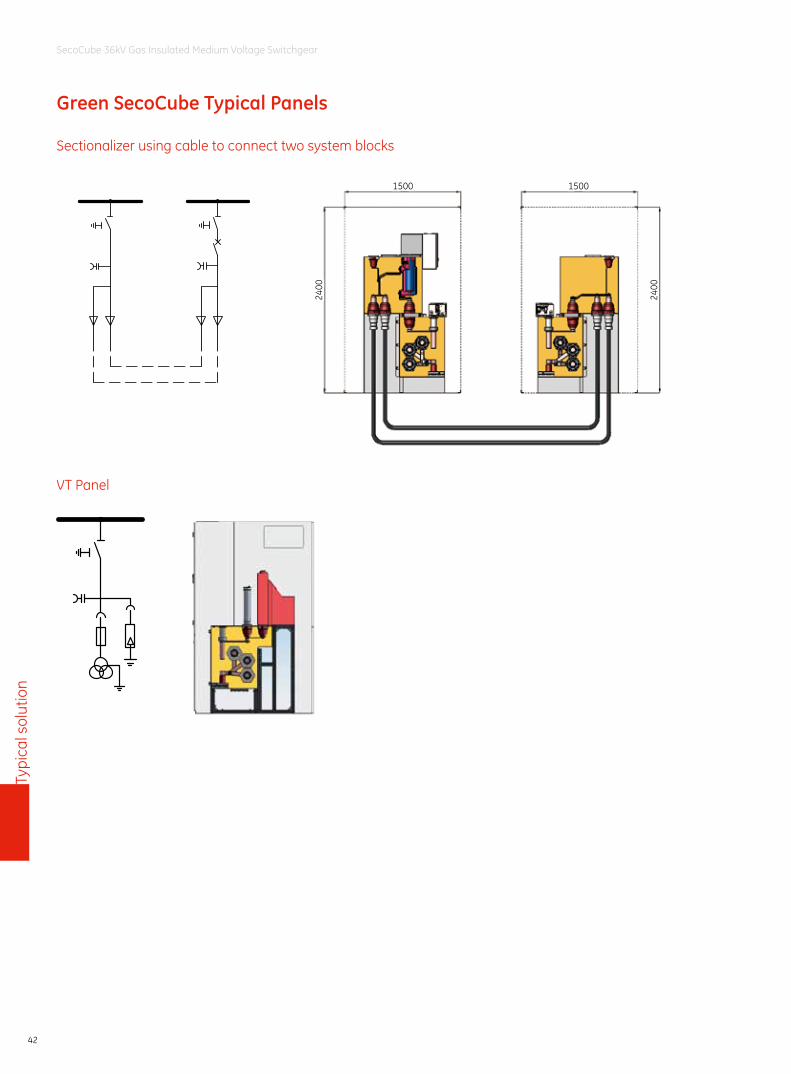
Sectionalizer using cable to connect two system blocks
VT Panel
1500
2400
2400
1500
Green SecoCube Typical Panels
43
SecoCube 36kV Gas Insulated Medium Voltage Switchgear
Typi
cal s
olut
ion
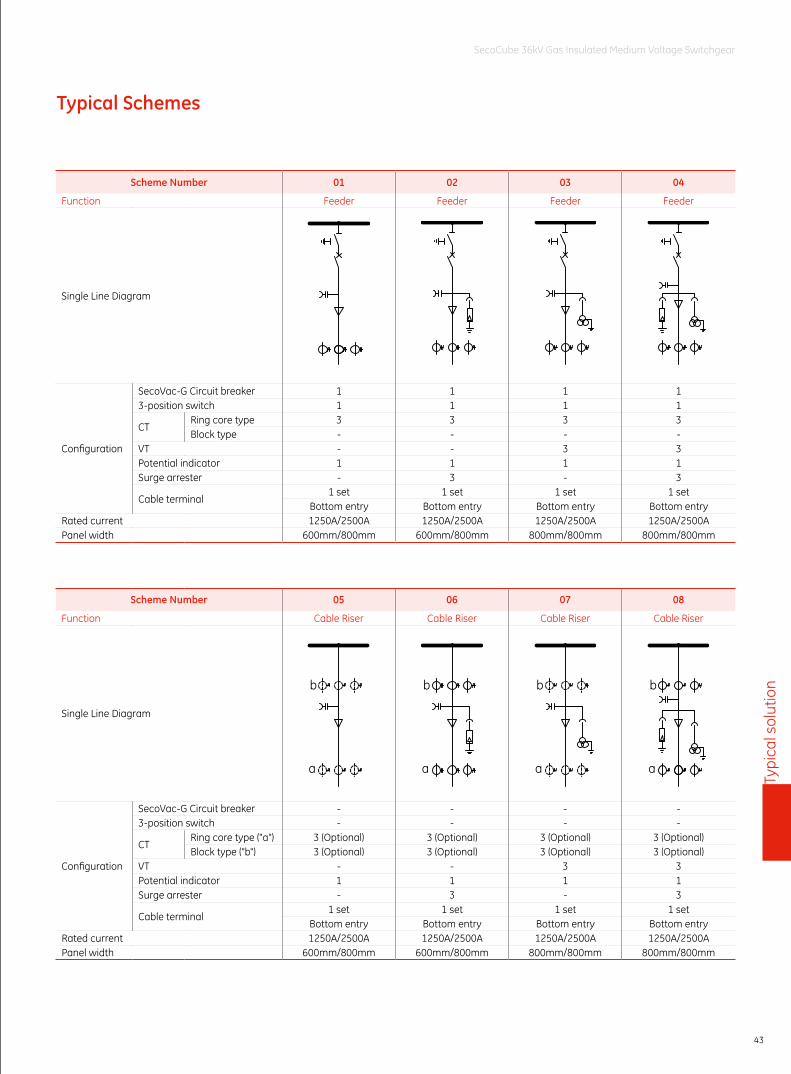
Typical Schemes
Scheme Number 01 02 03 04
Function Feeder Feeder Feeder Feeder
Single Line Diagram
Configuration
SecoVac-G Circuit breaker 1 1 1 13-position switch 1 1 1 1
CTRing core type 3 3 3 3Block type - - - -
VT - - 3 3Potential indicator 1 1 1 1Surge arrester - 3 - 3
Cable terminal1 set 1 set 1 set 1 set
Bottom entry Bottom entry Bottom entry Bottom entryRated current 1250A/2500A 1250A/2500A 1250A/2500A 1250A/2500APanel width 600mm/800mm 600mm/800mm 800mm/800mm 800mm/800mm
Scheme Number 05 06 07 08
Function Cable Riser Cable Riser Cable Riser Cable Riser
Single Line Diagram
b
a a
b
a
b b
a
Configuration
SecoVac-G Circuit breaker - - - -3-position switch - - - -
CTRing core type ("a") 3 (Optional) 3 (Optional) 3 (Optional) 3 (Optional)Block type ("b") 3 (Optional) 3 (Optional) 3 (Optional) 3 (Optional)
VT - - 3 3Potential indicator 1 1 1 1Surge arrester - 3 - 3
Cable terminal1 set 1 set 1 set 1 set
Bottom entry Bottom entry Bottom entry Bottom entryRated current 1250A/2500A 1250A/2500A 1250A/2500A 1250A/2500APanel width 600mm/800mm 600mm/800mm 800mm/800mm 800mm/800mm
44
SecoCube 36kV Gas Insulated Medium Voltage Switchgear
Typi
cal s
olut
ion
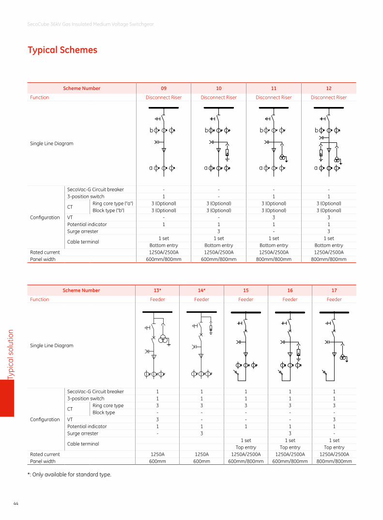
Typical Schemes
Scheme Number 09 10 11 12
Function Disconnect Riser Disconnect Riser Disconnect Riser Disconnect Riser
Single Line Diagram
b
a
b
a
b
a
b
a
Configuration
SecoVac-G Circuit breaker - - - -3-position switch 1 - 1 1
CTRing core type ("a") 3 (Optional) 3 (Optional) 3 (Optional) 3 (Optional)Block type ("b") 3 (Optional) 3 (Optional) 3 (Optional) 3 (Optional)
VT - - 3 3Potential indicator 1 1 1 1Surge arrester 3 - 3
Cable terminal1 set 1 set 1 set 1 set
Bottom entry Bottom entry Bottom entry Bottom entryRated current 1250A/2500A 1250A/2500A 1250A/2500A 1250A/2500APanel width 600mm/800mm 600mm/800mm 800mm/800mm 800mm/800mm
Scheme Number 13* 14* 15 16 17
Function Feeder Feeder Feeder Feeder Feeder
Single Line Diagram
Configuration
SecoVac-G Circuit breaker 1 1 1 1 13-position switch 1 1 1 1 1
CTRing core type 3 3 3 3 3Block type - - - - -
VT 3 - - - 3Potential indicator 1 1 1 1 1Surge arrester - 3 3 -
Cable terminal1 set 1 set 1 set
Top entry Top entry Top entryRated current 1250A 1250A 1250A/2500A 1250A/2500A 1250A/2500APanel width 600mm 600mm 600mm/800mm 600mm/800mm 800mm/800mm
*: Only available for standard type.
45
SecoCube 36kV Gas Insulated Medium Voltage Switchgear
Typi
cal s
olut
ion
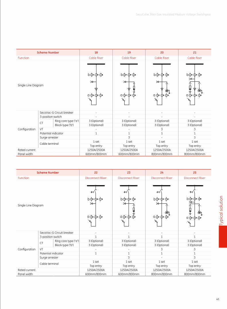
Scheme Number 18 19 20 21
Function Cable Riser Cable Riser Cable Riser Cable Riser
Single Line Diagram
b
a
b
a
b
a
b
a
Configuration
SecoVac-G Circuit breaker - - - -3-position switch - - - -
CTRing core type ("a") 3 (Optional) 3 (Optional) 3 (Optional) 3 (Optional)Block type ("b") 3 (Optional) 3 (Optional) 3 (Optional) 3 (Optional)
VT - - 3 3Potential indicator 1 1 1 1Surge arrester 3 - 3
Cable terminal1 set 1 set 1 set 1 set
Top entry Top entry Top entry Top entryRated current 1250A/2500A 1250A/2500A 1250A/2500A 1250A/2500APanel width 600mm/800mm 600mm/800mm 800mm/800mm 800mm/800mm
Scheme Number 22 23 24 25
Function Disconnect Riser Disconnect Riser Disconnect Riser Disconnect Riser
Single Line Diagram
b
a
b
a
b
a
b
a
Configuration
SecoVac-G Circuit breaker - - - -3-position switch 1 1 1 1
CTRing core type ("a") 3 (Optional) 3 (Optional) 3 (Optional) 3 (Optional)Block type ("b") 3 (Optional) 3 (Optional) 3 (Optional) 3 (Optional)
VT - - 3 3Potential indicator 1 1 1 1Surge arrester 3 - 3
Cable terminal1 set 1 set 1 set 1 set
Top entry Top entry Top entry Top entryRated current 1250A/2500A 1250A/2500A 1250A/2500A 1250A/2500APanel width 600mm/800mm 600mm/800mm 800mm/800mm 800mm/800mm
46
SecoCube 36kV Gas Insulated Medium Voltage Switchgear
Typi
cal s
olut
ion
Typical Schemes
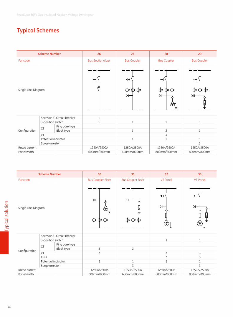
Scheme Number 26 27 28 29
Function Bus Sectionalizer Bus Coupler Bus Coupler Bus Coupler
Single Line Diagram
Configuration
SecoVac-G Circuit breaker 13-position switch 1 1 1 1
CTRing core type Block type 3 3 3
VT 3Potential indicator 1 1 1Surge arrester 3
Rated current 1250A/2500A 1250A/2500A 1250A/2500A 1250A/2500APanel width 600mm/800mm 600mm/800mm 800mm/800mm 800mm/800mm
Scheme Number 30 31 32 33
Function Bus Coupler Riser Bus Coupler Riser VT Panel VT Panel
Single Line Diagram
Configuration
SecoVac-G Circuit breaker3-position switch 1 1
CTRing core typeBlock type 3 3
VT 3 3 3Fuse 3 3Potential indicator 1 1 1 1Surge arrester 3 3
Rated current 1250A/2500A 1250A/2500A 1250A/2500A 1250A/2500APanel width 600mm/800mm 600mm/800mm 800mm/800mm 800mm/800mm
47
SecoCube 36kV Gas Insulated Medium Voltage Switchgear
Typi
cal s
olut
ion
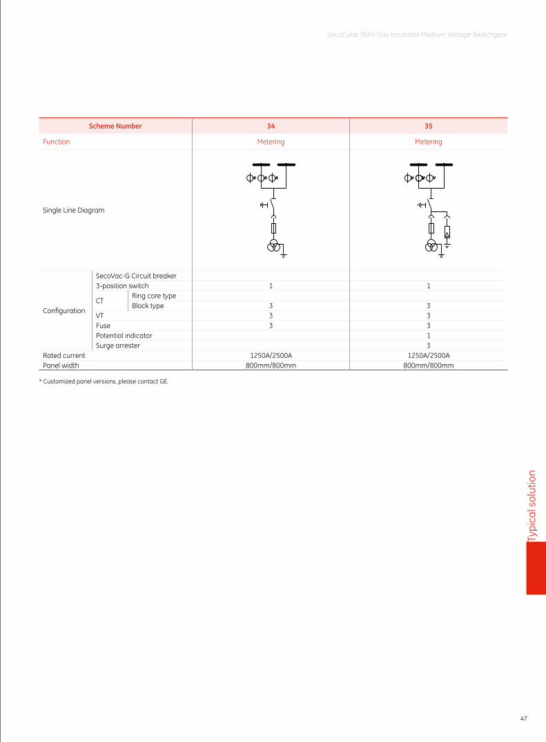
Scheme Number 34 35
Function Metering Metering
Single Line Diagram
Configuration
SecoVac-G Circuit breaker3-position switch 1 1
CTRing core type Block type 3 3
VT 3 3Fuse 3 3Potential indicator 1Surge arrester 3
Rated current 1250A/2500A 1250A/2500APanel width 800mm/800mm 800mm/800mm
* Customized panel versions, please contact GE.
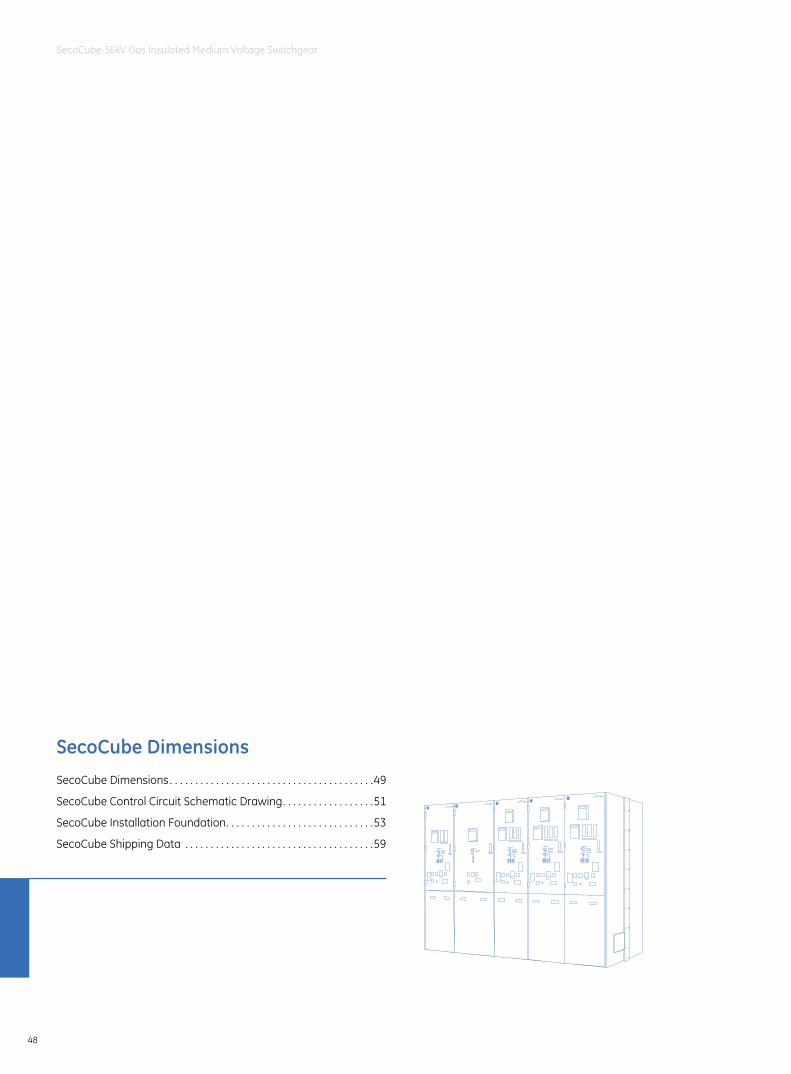
Seco
Cube
Dim
ensi
ons
48
SecoCube 36kV Gas Insulated Medium Voltage Switchgear
SecoCube DimensionsSecoCube Dimensions . . . . . . . . . . . . . . . . . . . . . . . . . . . . . . . . . . . . . . . .49
SecoCube Control Circuit Schematic Drawing . . . . . . . . . . . . . . . . . .51
SecoCube Installation Foundation . . . . . . . . . . . . . . . . . . . . . . . . . . . . .53
SecoCube Shipping Data . . . . . . . . . . . . . . . . . . . . . . . . . . . . . . . . . . . . .59
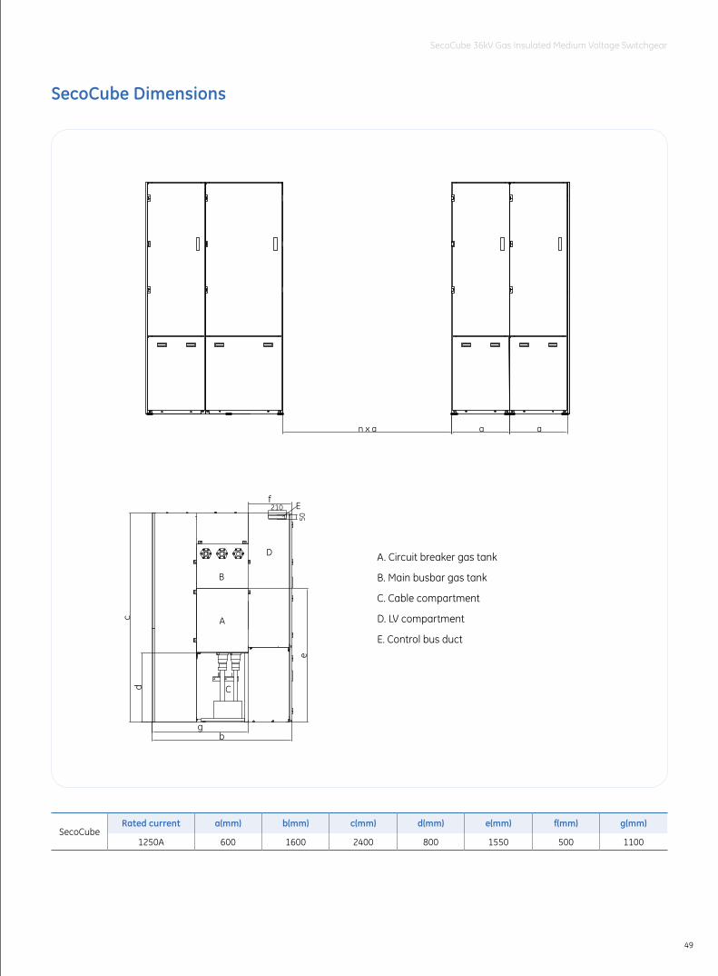
49
SecoCube 36kV Gas Insulated Medium Voltage Switchgear
SecoCube Dimensions
n x a a a
A
C
B
D
c
b
f
d
g
e50
210 E
A. Circuit breaker gas tank
B. Main busbar gas tank
C. Cable compartment
D. LV compartment
E. Control bus duct
SecoCubeRated current a(mm) b(mm) c(mm) d(mm) e(mm) f(mm) g(mm)
1250A 600 1600 2400 800 1550 500 1100
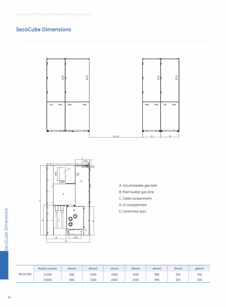
Seco
Cube
Dim
ensi
ons
50
SecoCube 36kV Gas Insulated Medium Voltage Switchgear
SecoCube Dimensions
n x a a a
A
B
D
C
b
c
50
210 F
d
g
e
f
E
E
200
450
420
145
SecoCube
Rated current a(mm) b(mm) c(mm) d(mm) e(mm) f(mm) g(mm)
1250A 600 1500 2400 1030 990 505 700
2500A 800 1500 2400 1030 990 505 700
A. Circuit breaker gas tank
B. Main busbar gas tank
C. Cable compartment
D. LV compartment
E. Control bus duct
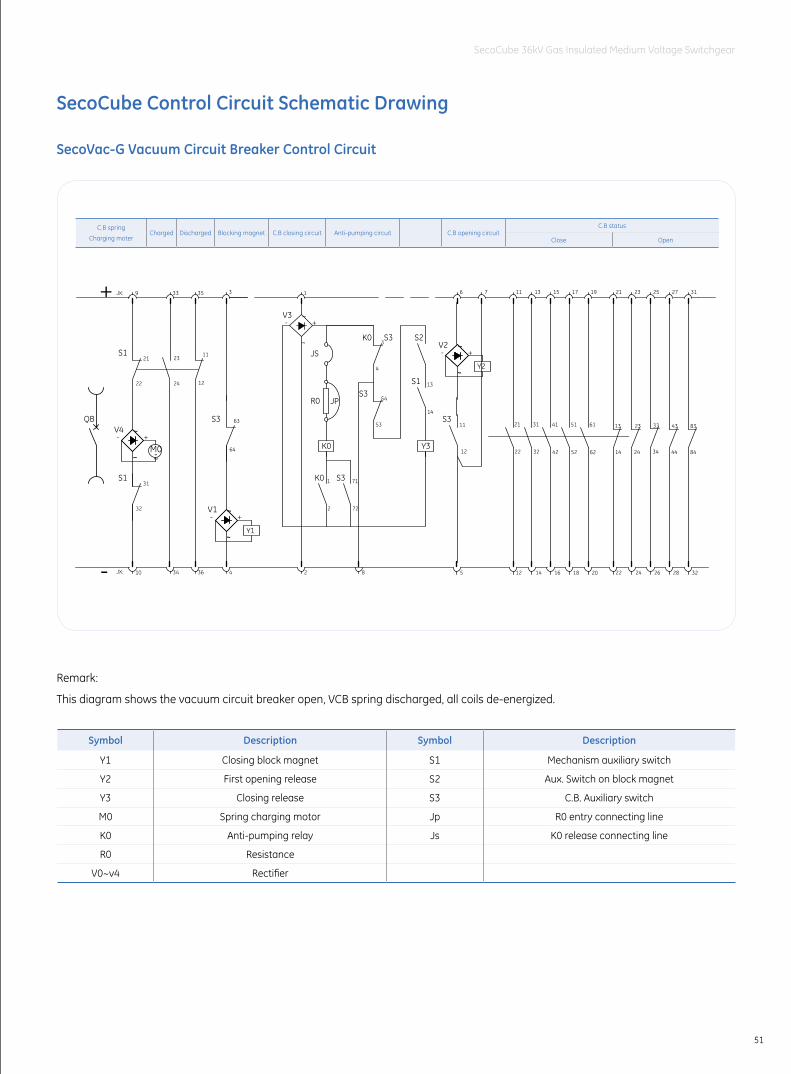
51
SecoCube 36kV Gas Insulated Medium Voltage Switchgear
SecoCube Control Circuit Schematic Drawing
SecoVac-G Vacuum Circuit Breaker Control Circuit
Remark:
This diagram shows the vacuum circuit breaker open, VCB spring discharged, all coils de-energized.
Symbol Description Symbol Description
Y1 Closing block magnet S1 Mechanism auxiliary switch
Y2 First opening release S2 Aux. Switch on block magnet
Y3 Closing release S3 C.B. Auxiliary switch
M0 Spring charging motor Jp R0 entry connecting line
K0 Anti-pumping relay Js K0 release connecting line
R0 Resistance
V0~v4 Rectifier
3410 36 5 14 16
11
2422 12
2321
33+ 9 35
12
11
32 42 14
4131 13
6 7 1513
12
22
21
11
~
~
32
31
24 26
2523
22
21
28
27
24
23
34
33
44
43
4
~
~
3
18
52
51
17
Y3
14
13
53
54
4
3
K0
R0 JP
~
~
2
1
72
71
1
2
JS
S2
S1
S3K0
S3
S3K0
S1
S1
S3 S3
-
QB
JX:
JX:
M0~-~
~
Y1~
~+
V1-
V4+-
V3+-
63
64
20
62
61
19
32
31
84
83
~
~
~
~
Y2
+V2-
8
C.B spring
Charging moterCharged Discharged Blocking magnet C.B closing circuit Anti-pumping circuit C.B opening circuit
C.B status
Close Open
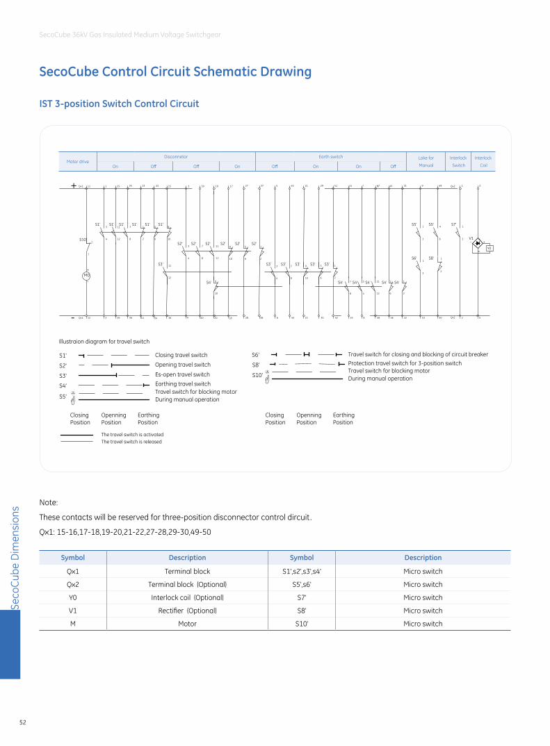
Seco
Cube
Dim
ensi
ons
52
SecoCube 36kV Gas Insulated Medium Voltage Switchgear
IST 3-position Switch Control Circuit
Note:
These contacts will be reserved for three-position disconnector control dircuit.
Qx1: 15-16,17-18,19-20,21-22,27-28,29-30,49-50
Symbol Description Symbol Description
Qx1 Terminal block S1',s2',s3',s4' Micro switch
Qx2 Terminal block (Optional) S5',s6' Micro switch
Y0 Interlock coil (Optional) S7' Micro switch
V1 Rectifier (Optional) S8' Micro switch
M Motor S10' Micro switch
Earth switchMotor drive
DisconnetorOn Off OnOff
Loke forManualOff On On Off
212 26 28 6
4
3
1+ 11 25 19 17 27 37 5
1
2
30
29
22
21
42
41
1036
35 13 9
44
4315 39
16
S10'
- Qx1:
Qx1:
M0-
+
24 8 48 46 32
31
50
49
S1'
8
7S1'
2
1S1'
6
5S1'
10
9S1'
S3'
4
3S2'
8
7S2'
12
11S2'
10
9
6
5
2
1
S3' S3' S3' S3' S3'
6
5
2
1
10
9S4'
3
S5'
S6'
6
S5'
S8'
33 3 23 7 45
41
3
1
2
1
12
11
4
3
8
72
1
6
5
10
9
8
7
4
3
12
11
12
11
14 34 4 40 20 18 38
47
S4' S4' S4' S4' S4'
S2' S2' S2'
S1'
3
S7' 1
1
2
3
4
Qx2:
Qx2:
~
~
Y0~
~+
V1-
Interlock Switch
Interlock Coil
Illustraion diagram for travel switch
Opening travel switch
Es-open travel switch
Travel switch for blocking motorDuring manual operation
Travel switch for closing and blocking of circuit breakerProtection travel switch for 3-position switch
Earthing travel switch
The travel switch is activatedThe travel switch is released
ClosingPosition
OpenningPosition
EarthingPosition
ClosingPosition
OpenningPosition
EarthingPosition
S1'
S3'
S2'
S4'
S5'
S6'
S8'
S10'
Closing travel switch
Travel switch for blocking motorDuring manual operation
Motor driveDisconnetor Earth switch Loke for
Manual
Interlock
Switch
Interlock
CoilOn Off Off On Off On On Off
SecoCube Control Circuit Schematic Drawing
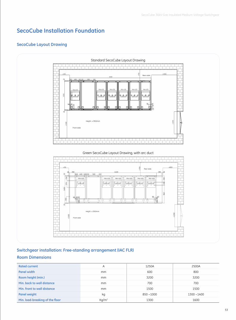
53
SecoCube 36kV Gas Insulated Medium Voltage Switchgear
1550
2525
80
85
60 80
8510
0
60
4400
400 500100 100 150 150
>700 >1000
>120
0
>150
0
>100
170 170
Min 470Min 470
170170450
170 170
Min 470
170 170
Min 470
170 170
Min 470
170 170
Min 470
100
100
Height 2900mm
Front aisle
Rear aisle
SecoCube Installation Foundation
SecoCube Layout Drawing
Switchgear installation: Free-standing arrangement (IAC FLR)
Room Dimensions
Rated current A 1250A 2500A
Panel width mm 600 800
Room height (min.) mm 3200 3200
Min. back to wall distance mm 700 700
Min. front to wall distance mm 1500 1500
Panel weight kg 850 ~1000 1300 ~1400
Min. load-breaking of the floor Kg/m2 1300 1600
1450
2525
Min 450
170 170
370
250
350
170 170 170 170
Min 450 Min 450
80 8510
0
60 80
8510
0
60
4400280400 500100 100150 150
48
338
150
962
280 48
170 170
Min 450
170 170
Min 450
170 170
Min 450
>700 >800
>120
0
>150
0
>50
Height 2900mm
Rear aisle
Front aisle
Standard SecoCube Layout Drawing
Green SecoCube Layout Drawing, with arc duct
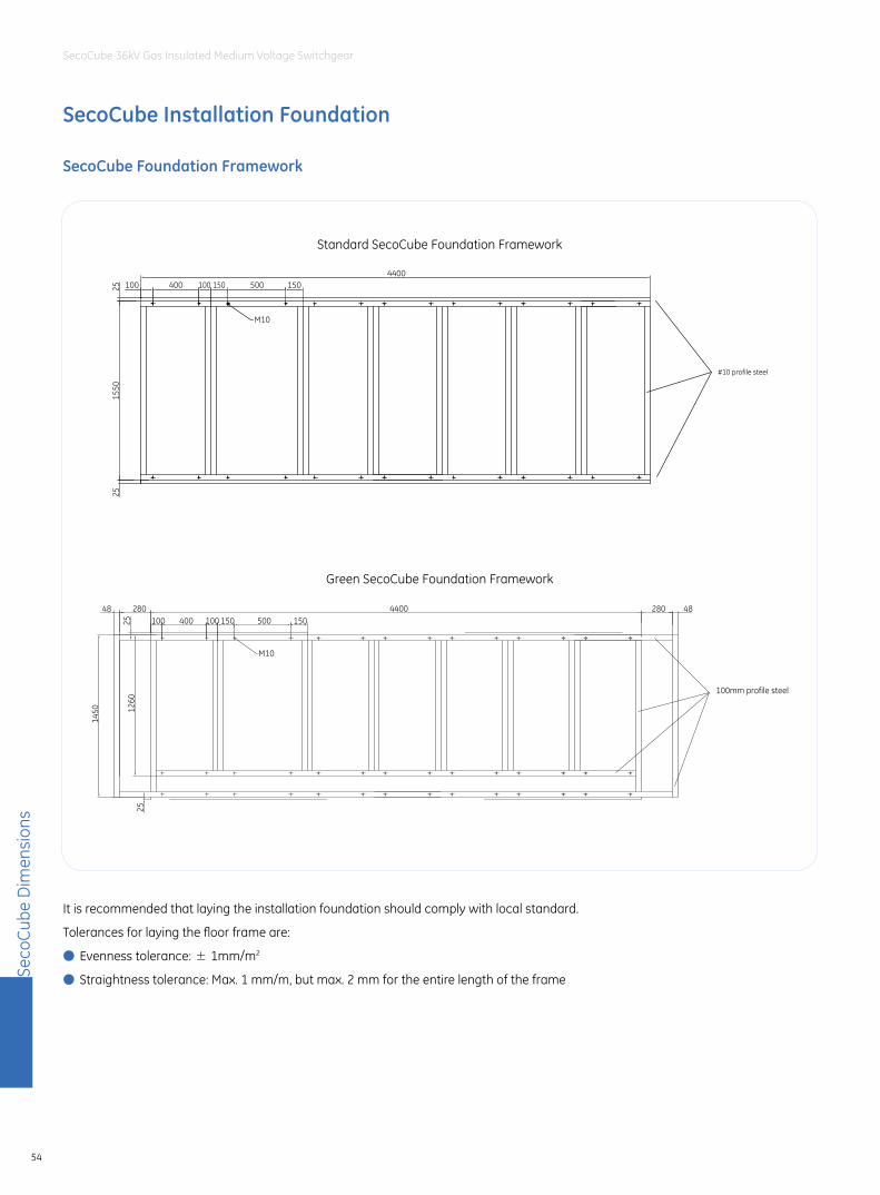
Seco
Cube
Dim
ensi
ons
54
SecoCube 36kV Gas Insulated Medium Voltage Switchgear
SecoCube Foundation Framework
It is recommended that laying the installation foundation should comply with local standard.
Tolerances for laying the floor frame are:
● Evenness tolerance: ± 1mm/m2
● Straightness tolerance: Max. 1 mm/m, but max. 2 mm for the entire length of the frame
1450
2525
4400280400 500100 150 150
48 280 48
M10
100
100mm profile steel
1260
SecoCube Installation Foundation
#10 profile steel
100
M10
150150100 5004004400
2525
1550
Standard SecoCube Foundation Framework
Green SecoCube Foundation Framework
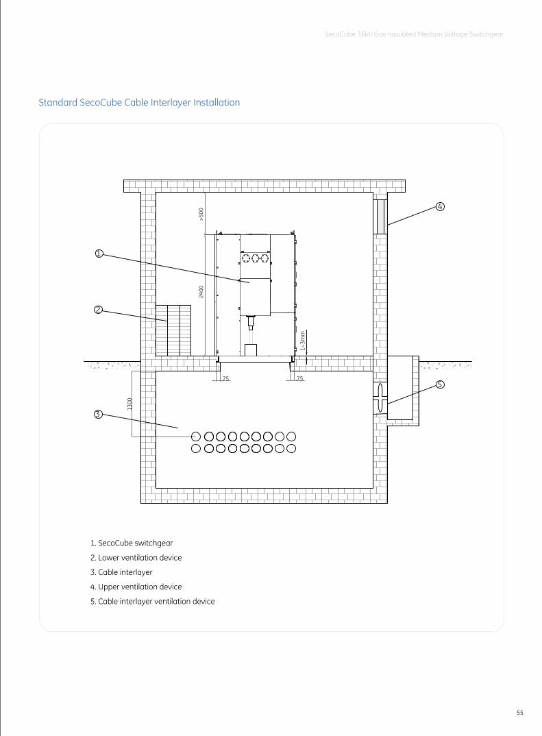
55
SecoCube 36kV Gas Insulated Medium Voltage Switchgear
1. SecoCube switchgear
2. Lower ventilation device
3. Cable interlayer
4. Upper ventilation device
5. Cable interlayer ventilation device
5
4
3
1300
>500
75
1
21~
3mm
2400
75
Standard SecoCube Cable Interlayer Installation
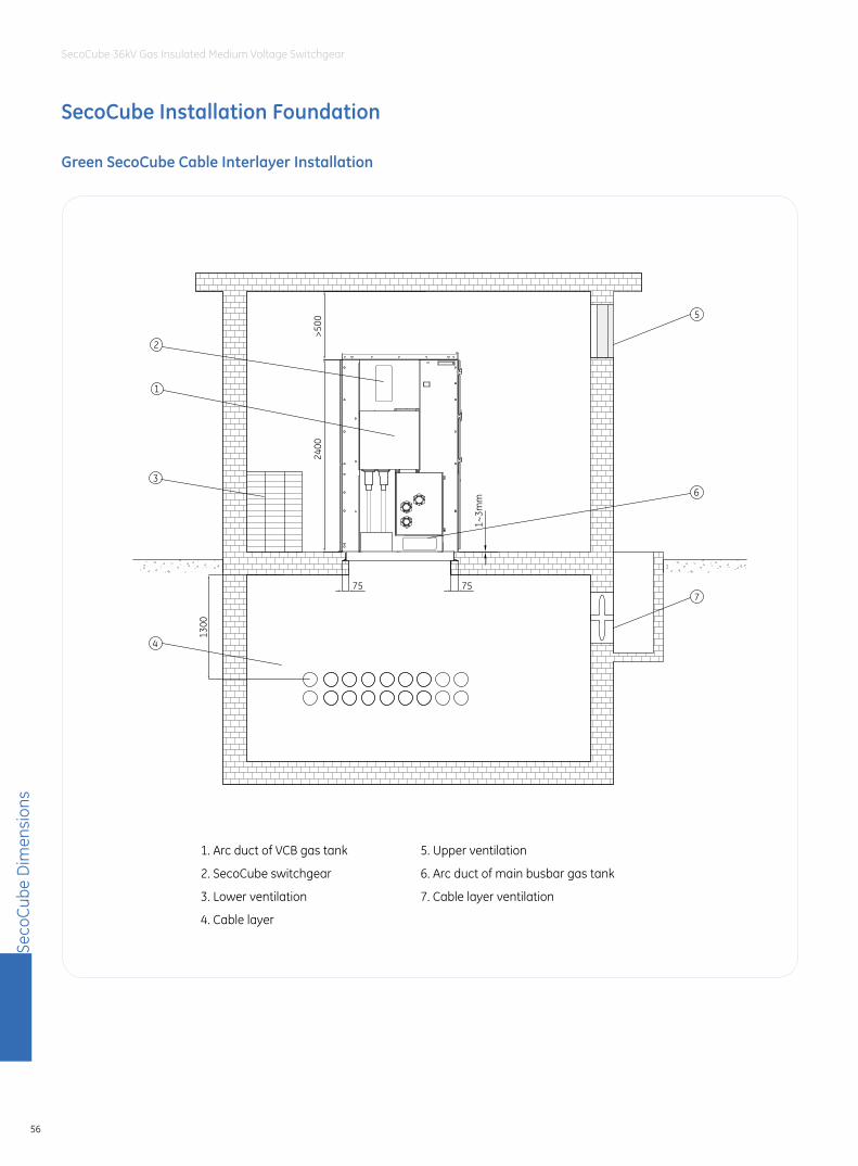
Seco
Cube
Dim
ensi
ons
56
SecoCube 36kV Gas Insulated Medium Voltage Switchgear
SecoCube Installation Foundation
Green SecoCube Cable Interlayer Installation
1. Arc duct of VCB gas tank
2. SecoCube switchgear
3. Lower ventilation
4. Cable layer
5. Upper ventilation
6. Arc duct of main busbar gas tank
7. Cable layer ventilation
7
6
5
4
1300
>500
75
2
1
31~
3mm
2400
75
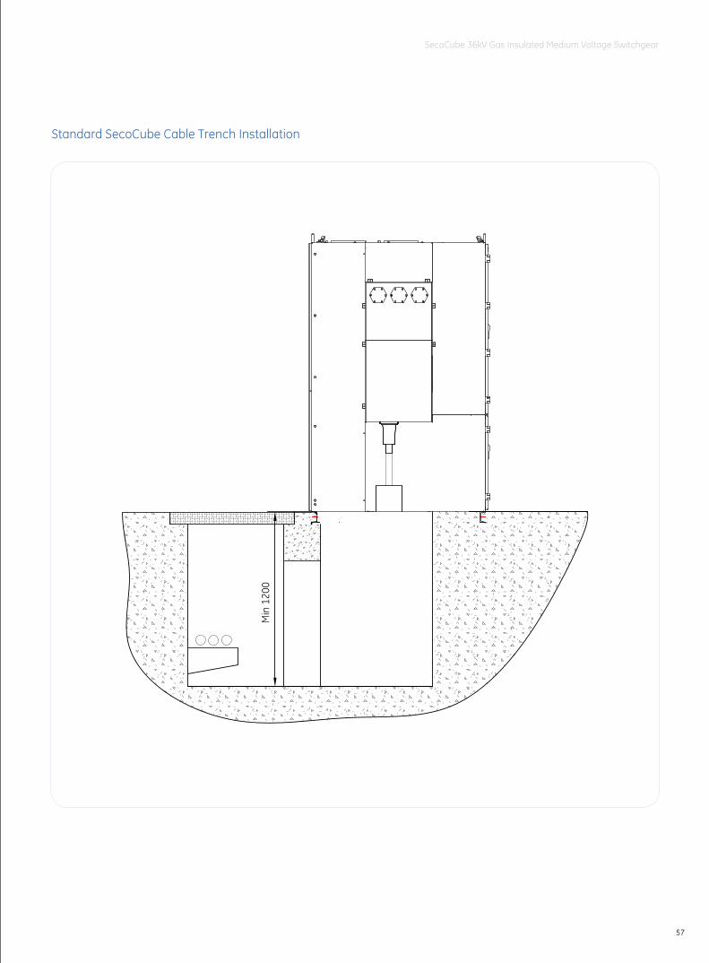
57
SecoCube 36kV Gas Insulated Medium Voltage Switchgear
Min
120
0
Standard SecoCube Cable Trench Installation
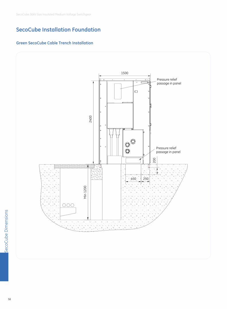
Seco
Cube
Dim
ensi
ons
58
SecoCube 36kV Gas Insulated Medium Voltage Switchgear
Green SecoCube Cable Trench Installation
SecoCube Installation Foundation
2400
1500
Min
120
0
450 250
200
Pressure reliefpassage in panel
Pressure reliefpassage in panel
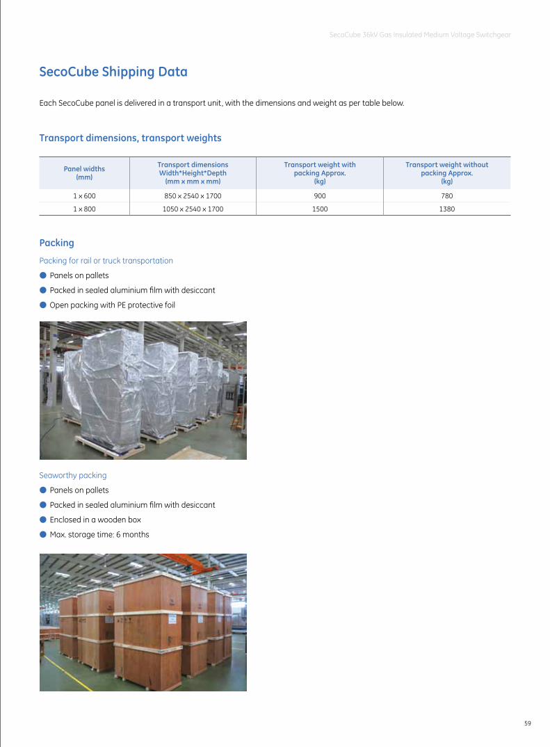
59
SecoCube 36kV Gas Insulated Medium Voltage Switchgear
SecoCube Shipping Data
Each SecoCube panel is delivered in a transport unit, with the dimensions and weight as per table below.
Transport dimensions, transport weights
Packing
Panel widths(mm)
Transport dimensionsWidth*Height*Depth
(mm x mm x mm)
Transport weight with packing Approx.
(kg)
Transport weight without packing Approx.
(kg)
1 x 600 850 x 2540 x 1700 900 780
1 x 800 1050 x 2540 x 1700 1500 1380
Packing for rail or truck transportation
● Panels on pallets
● Packed in sealed aluminium film with desiccant
● Open packing with PE protective foil
Seaworthy packing
● Panels on pallets
● Packed in sealed aluminium film with desiccant
● Enclosed in a wooden box
● Max. storage time: 6 months
Japan11F, Akasaka Park Bldg.,5-2-20, Akasaka, Minato-kuTokyo 107-6111T : +81 3 3588 5288F : +81 3 3585 3010
North AsiaKorea22, Daewangpangyo-ro 712 beon-gil, Bundang-gu, Seongnam-si, Gyeonggi-do, 463-400, KoreaT: +82-31-620-6000F: +82-31-620-7070
MalaysiaLevel 6, 1 Sentral, Jalan Travers, Kuala Lumpur SentralKuala Lumpur, Malaysia 50470T : +603 2273 9788F : +603 2273 7988
Thailand25th floor, CRC Tower, All Seasons Place, 87/2 Wireless Road, Lumpini, Pathumwan, Bangkok 10330T : +66 2 648 0240F : +66 2 648 0200
IndonesiaBRI II Tower, 27th floor, Jl. Jend. Sudirman No. 44-46Jakarta 10210T: +62 21 573 0430F: +62 21 574 7089
Singapore240 Tanjong Pagar Road, #06-00 GE TowerSingapore 088540T : +65 6326 3718F : +65 6326 3015
Philippines8F Net Cube Building, 30th Street, Corner 3rd Avenue, Crescent West Park, Global City Taguig 1634T : +63 2 877 7000F : +63 2 846 0629
VietnamSaigon Centre, Unit 1, Floor 7, Le Loi Boulevard, District 1HoChiMinh CityT : +84 8 3914 6700F : +84 8 3827 8229
South East Asia
Australia125-127 Long Street, Smithfield, Sydney, NSW 2164T : +61 2 8788 6911F : +61 2 8788 7224
Australia & New ZealandNew ZealandLevel 1, 8 Tangihua Street, Auckland, North IslandT : +64 9 353 6706F : +64 9 353 6707
IndiaPolt No. 42/1 & 45/14, Electronic City-Phase IIBangalore-560100T: (080) 41434000F: (080) 41434199
India
Shanghai4F, Building 2, CTP, No.1 Hua Tuo Rd. Zhang Jiang Hi-Tech Park, Shanghai, China 201203T : +86 21 3877 7888F : +86 21 3877 7600
Taiwan6F, No. 8, Min Sheng E. Rd., Sec. 3, Taipei 10480T : +886 2 2183 7000F : +886 2 2516 6829
Greater China
SpainP.I. Clot del Tufau, s/n, E-08295 Sant Vicenç de CastelletT: +34 900 993 625
BelgiumNieuwevaart 51, B-9000 GentT: +32 (0)9 265 21 11
FinlandKuortaneenkatu 2, FI-00510 HelsinkiT: +358 (0)10 394 3760
FranceParis Nord 2, 13, rue de la PerdrixF-95958 Roissy CDG CédexT: +33 (0)800 912 816
PolandUl. Odrowaza 15, 03-310 WarszawaT: +48 22 519 76 00andUl. Leszczyńska 6, Bielsko-Biała 43-300T: +48 33 828 62 33
Europe & Middle EastItalyCentro Direzionale ColleoniVia Paracelso 16, Palazzo Andromeda B1 I-20864 Agrate Brianza (MB)T: +39 039 637 3701
NetherlandsParallelweg 10, Nl-7482 CA HaaksbergenT: +31 (0)53 573 03 03
GermanyRobert-Bosch Str. 2a, 50354 Hürth-EfferenT: +49 (0) 2233/ 9719-0
PortugalRua Camilo Castelo Branco, 805, Apartado 27704401-601 Vila Nova de GaiaT: +351 22 374 60 00
HungaryVaci ut 81-83. H-1139 BudapestT: +36 1 447 6050
Russia27/8, Electrozavodskaya street, Moscow, 107023T: +7 495 937 11 11
South AfricaUnit 4, 130 Gazelle Avenue, Corporate Park Midrand 1685P.O. Box 76672 Wendywood 2144T: +27 11 238 3000
United Arab EmiratesInjaz Building, 3rd FloorDubai Internet City, PO Box 11549, DubaiT: +971 4 4546912
United Kingdom2 The Arena, Downshire WayBracknell, BerkshireRG12 1PUT: +44 (0) 800 587 1239
Latin America790 N.W. 107th Avenue, Suite 200, Miami, Fl 33172 USAT: +1 305 551 5155
ChileVespucio Norte, Avenida Presidente Eduardo FreiMontalva 6001, Edificio N° 66Comuna: Conchalí, Sector el Cortijo, SantiagoT: (56 2) 928-4700
Latin AmericaBrazilAv. María Coelho Aguiar, 215, Bloco C - 6.AndarJd.São Luiz, 05804-900, São PauloT: +55 11 36141900
MexicoAv. Churubusco 3900 Nte, Col. Industrial Benito JuárezMonterrey, N.L. 64517T: (01-800) 800-1968
USA41 Woodford Avenue, Plainville CT, USA 06062and12305 Kurland Drive, Houston, TX USA 77034T: +1 800-431-7867
North America
Printing Code: IN201301B06EN
© Copyright GE Industrial Solutions 2013
For more information, please visitwww.geindustrial.com