Embed Size (px)
Citation preview
No. CP-SS-1797E
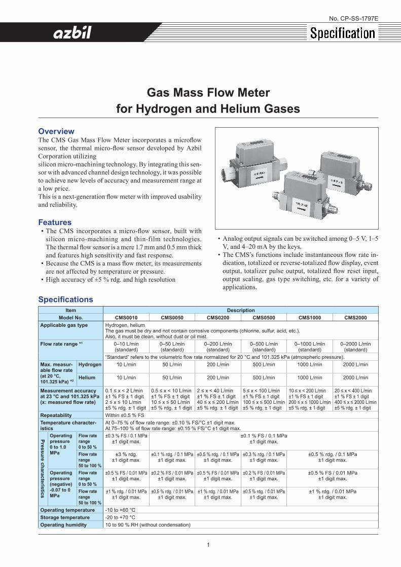
Gas Mass Flow Meterfor Hydrogen and Helium Gases
OverviewThe CMS Gas Mass Flow Meter incorporates a microflow sensor, the thermal micro-flow sensor developed by Azbil Corporation utilizing silicon micro-machining technology. By integrating this sen-sor with advanced channel design technology, it was possible to achieve new levels of accuracy and measurement range at a low price.This is a next-generation flow meter with improved usability and reliability.
Features• The CMS incorporates a micro-flow sensor, built with
silicon micro-machining and thin-film technologies. The thermal flow sensor is a mere 1.7 mm and 0.5 mm thick and features high sensitivity and fast response.
• Because the CMS is a mass flow meter, its measurements are not affected by temperature or pressure.
• High accuracy of ±5 % rdg. and high resolution
• Analog output signals can be switched among 0–5 V, 1–5 V, and 4–20 mA by the keys.
• The CMS’s functions include instantaneous flow rate in-dication, totalized or reverse-totalized flow display, event output, totalizer pulse output, totalized flow reset input, output scaling, gas type switching, etc. for a variety of applications.
SpecificationsItem Description
Model No. CMS0010 CMS0050 CMS0200 CMS0500 CMS1000 CMS2000Applicable gas type Hydrogen, helium
The gas must be dry and not contain corrosive components (chlorine, sulfur, acid, etc.).Also, it must be clean, without dust or oil mist.
Flow rate range *1 0–10 L/min(standard)
0–50 L/min(standard)
0–200 L/min(standard)
0–500 L/min(standard)
0–1000 L/min(standard)
0–2000 L/min(standard)
“Standard” refers to the volumetric flow rate normalized for 20 °C and 101.325 kPa (atmospheric pressure).Max. measur-able flow rate(at 20 °C, 101.325 kPa) *2
Hydrogen 10 L/min 50 L/min 200 L/min 500 L/min 1000 L/min 2000 L/min
Helium 10 L/min 50 L/min 200 L/min 500 L/min 1000 L/min 2000 L/min
Measurement accuracyat 23 °C and 101.325 kPa(x: measured flow rate)
0.1 ≤ x < 2 L/min±1 % FS ± 1 digit2 ≤ x ≤ 10 L/min±5 % rdg. ± 1 digit
0.5 ≤ x < 10 L/min±1 % FS ± 1 digit10 ≤ x ≤ 50 L/min±5 % rdg. ± 1 digit
2 ≤ x < 40 L/min±1 % FS ± 1 digit40 ≤ x ≤ 200 L/min±5 % rdg. ± 1 digit
5 ≤ x < 100 L/min±1 % FS ± 1 digit100 ≤ x ≤ 500 L/min±5 % rdg. ± 1 digit
10 ≤ x < 200 L/min±1 % FS ± 1 digit200 ≤ x ≤ 1000 L/min±5 % rdg. ± 1 digit
20 ≤ x < 400 L/min±1 % FS ± 1 digit400 ≤ x ≤ 2000 L/min±5 % rdg. ± 1 digit
Repeatability Within ±0.5 % FSTemperature character-istics
At 0–75 % of flow rate range: ±0.10 % FS/°C ±1 digit max.At 75–100 % of flow rate range: ±0.15 % FS/°C ±1 digit max.
Pressure characteristics
Operating pressure0 to 1.0 MPa
Flow rate range0 to 50 %
±0.3 % FS / 0.1 MPa±1 digit max.
±0.1 % FS / 0.1 MPa±1 digit max.
Flow rate range50 to 100 %
±3 % rdg.±1 digit max.
±0.1 % rdg. / 0.1 MPa±1 digit max.
±0.5 % rdg. / 0.1 MPa±1 digit max.
±0.3 % rdg. / 0.1 MPa±1 digit max.
±0.5 % rdg. / 0.1 MPa±1 digit max.
Operating pressure (negative)-0.07 to 0 MPa
Flow rate range0 to 50 %
±0.5 % FS / 0.01 MPa±1 digit max.
±0.2 % FS / 0.01 MPa±1 digit max.
±0.5 % FS / 0.01 MPa ±1 digit max.
±0.2 % FS / 0.01 MPa±1 digit max.
±0.5 % FS / 0.01 MPa±1 digit max.
Flow rate range50 to 100 %
±1 % rdg. / 0.01 MPa±1 digit max.
±0.5 % rdg. / 0.01 MPa±1 digit max.
±1 % rdg. / 0.01 MPa±1 digit max.
±0.5 % rdg. / 0.01 MPa±1 digit max.
±1 % rdg. / 0.01 MPa±1 digit max.
Operating temperature -10 to +60 °CStorage temperature -20 to +70 °COperating humidity 10 to 90 % RH (without condensation)
1
Item DescriptionModel No. CMS0010 CMS0050 CMS0200 CMS0500 CMS1000 CMS2000
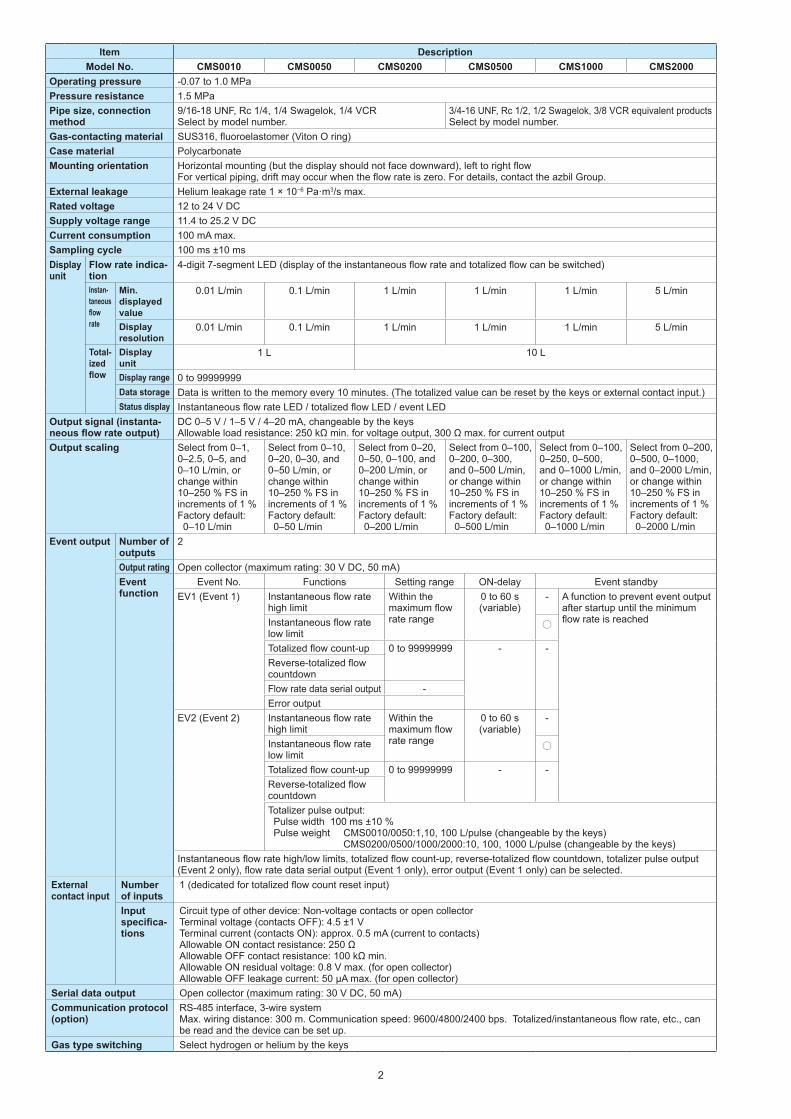
Operating pressure -0.07 to 1.0 MPaPressure resistance 1.5 MPaPipe size, connection method
9/16-18 UNF, Rc 1/4, 1/4 Swagelok, 1/4 VCRSelect by model number.
3/4-16 UNF, Rc 1/2, 1/2 Swagelok, 3/8 VCR equivalent productsSelect by model number.
Gas-contacting material SUS316, fluoroelastomer (Viton O ring)Case material PolycarbonateMounting orientation Horizontal mounting (but the display should not face downward), left to right flow
For vertical piping, drift may occur when the flow rate is zero. For details, contact the azbil Group.External leakage Helium leakage rate 1 × 10⁻⁶ Pa·m3/s max.Rated voltage 12 to 24 V DCSupply voltage range 11.4 to 25.2 V DCCurrent consumption 100 mA max.Sampling cycle 100 ms ±10 msDisplay unit
Flow rate indica-tion
4-digit 7-segment LED (display of the instantaneous flow rate and totalized flow can be switched)
Instan-taneous flow rate
Min. displayed value
0.01 L/min 0.1 L/min 1 L/min 1 L/min 1 L/min 5 L/min
Display resolution
0.01 L/min 0.1 L/min 1 L/min 1 L/min 1 L/min 5 L/min
Total-ized flow
Display unit
1 L 10 L
Display range 0 to 99999999Data storage Data is written to the memory every 10 minutes. (The totalized value can be reset by the keys or external contact input.)Status display Instantaneous flow rate LED / totalized flow LED / event LED
Output signal (instanta-neous flow rate output)
DC 0–5 V / 1–5 V / 4–20 mA, changeable by the keysAllowable load resistance: 250 kΩ min. for voltage output, 300 Ω max. for current output
Output scaling Select from 0–1, 0–2.5, 0–5, and 0–10 L/min, or change within 10–250 % FS in increments of 1 %Factory default: 0–10 L/min
Select from 0–10, 0–20, 0–30, and 0–50 L/min, or change within 10–250 % FS in increments of 1 %Factory default: 0–50 L/min
Select from 0–20, 0–50, 0–100, and 0–200 L/min, or change within 10–250 % FS in increments of 1 %Factory default: 0–200 L/min
Select from 0–100, 0–200, 0–300, and 0–500 L/min, or change within 10–250 % FS in increments of 1 % Factory default: 0–500 L/min
Select from 0–100, 0–250, 0–500, and 0–1000 L/min, or change within 10–250 % FS in increments of 1 %Factory default: 0–1000 L/min
Select from 0–200, 0–500, 0–1000, and 0–2000 L/min, or change within 10–250 % FS in increments of 1 %Factory default: 0–2000 L/min
Event output Number of outputs
2
Output rating Open collector (maximum rating: 30 V DC, 50 mA)Event function
Event No. Functions Setting range ON-delay Event standbyEV1 (Event 1) Instantaneous flow rate
high limitWithin the maximum flow rate range
0 to 60 s(variable)
- A function to prevent event output after startup until the minimum flow rate is reachedInstantaneous flow rate
low limitTotalized flow count-up 0 to 99999999 - -Reverse-totalized flow countdownFlow rate data serial output -Error output
EV2 (Event 2) Instantaneous flow rate high limit
Within the maximum flow rate range
0 to 60 s(variable)
-
Instantaneous flow rate low limitTotalized flow count-up 0 to 99999999 - -Reverse-totalized flow countdownTotalizer pulse output: Pulse width 100 ms ±10 % Pulse weight CMS0010/0050:1,10, 100 L/pulse (changeable by the keys)
CMS0200/0500/1000/2000:10, 100, 1000 L/pulse (changeable by the keys)Instantaneous flow rate high/low limits, totalized flow count-up, reverse-totalized flow countdown, totalizer pulse output (Event 2 only), flow rate data serial output (Event 1 only), error output (Event 1 only) can be selected.
External contact input
Number of inputs
1 (dedicated for totalized flow count reset input)
Input specifica-tions
Circuit type of other device: Non-voltage contacts or open collectorTerminal voltage (contacts OFF): 4.5 ±1 VTerminal current (contacts ON): approx. 0.5 mA (current to contacts)Allowable ON contact resistance: 250 ΩAllowable OFF contact resistance: 100 kΩ min.Allowable ON residual voltage: 0.8 V max. (for open collector)Allowable OFF leakage current: 50 μA max. (for open collector)
Serial data output Open collector (maximum rating: 30 V DC, 50 mA)Communication protocol(option)
RS-485 interface, 3-wire systemMax. wiring distance: 300 m. Communication speed: 9600/4800/2400 bps. Totalized/instantaneous flow rate, etc., can be read and the device can be set up.
Gas type switching Select hydrogen or helium by the keys
2
Item DescriptionModel No. CMS0010 CMS0050 CMS0200 CMS0500 CMS1000 CMS2000
Gas type conversion function
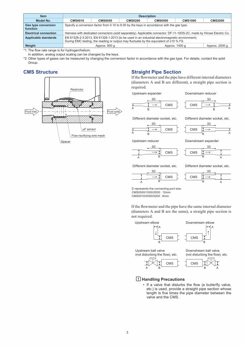
Specify a conversion factor from 0.10 to 8.00 by the keys in accordance with the gas type.
Electrical connection Harness with dedicated connectors (sold separately). Applicable connector: DF-11-10DS-2C, made by Hirose Electric Co.Applicable standards EN 61326-2-3:2013, EN 61326-1:2013 (to be used in an industrial electromagnetic environment)
During EMC testing, the reading or output may fluctuate by the equivalent of ±10 % FS.Weight Approx. 800 g Approx. 1400 g Approx. 2000 g
*1. The flow rate range is for hydrogen/helium. In addition, analog output scaling can be changed by the keys.
*2. Other types of gases can be measured by changing the conversion factor in accordance with the gas type. For details, contact the azbil Group.
CMS Structure
Restrictor
Fluid inlet Fluid outlet
μF sensor
Flow rectifying wire mesh
Spacer
Straight Pipe SectionIf the flowmeter and the pipe have different internal diameters (diameters A and B are different), a straight pipe section is required.
CMS CMSB B
5D
A A
B B
5D 3D
3D
A ACMS CMS
Upstream expander Downstream reducer
Different diameter socket, etc. Different diameter socket, etc.
CMS CMS
5D
B
BB
5D 3D
3D
AA
B AA
CMS CMS
Upstream reducer Downstream expander
Different diameter socket, etc. Different diameter socket, etc.
D represents the connecting port size.CMS0500/1000/2000 : 12mmCMS0010/0050/0200 : 6mm
If the flowmeter and the pipe have the same internal diameter (diameters A and B are the same), a straight pipe section is not required.
CMS CMS
A
BB
CMS CMSBA B A
Upstream elbow Downstream elbow
Upstream ball valve (not disturbing the flow), etc.
Downstream ball valve (not disturbing the flow), etc.
A
Handling Precautions• If a valve that disturbs the flow (a butterfly valve,
etc.) is used, provide a straight pipe section whose length is five times the pipe diameter between the valve and the CMS.
3
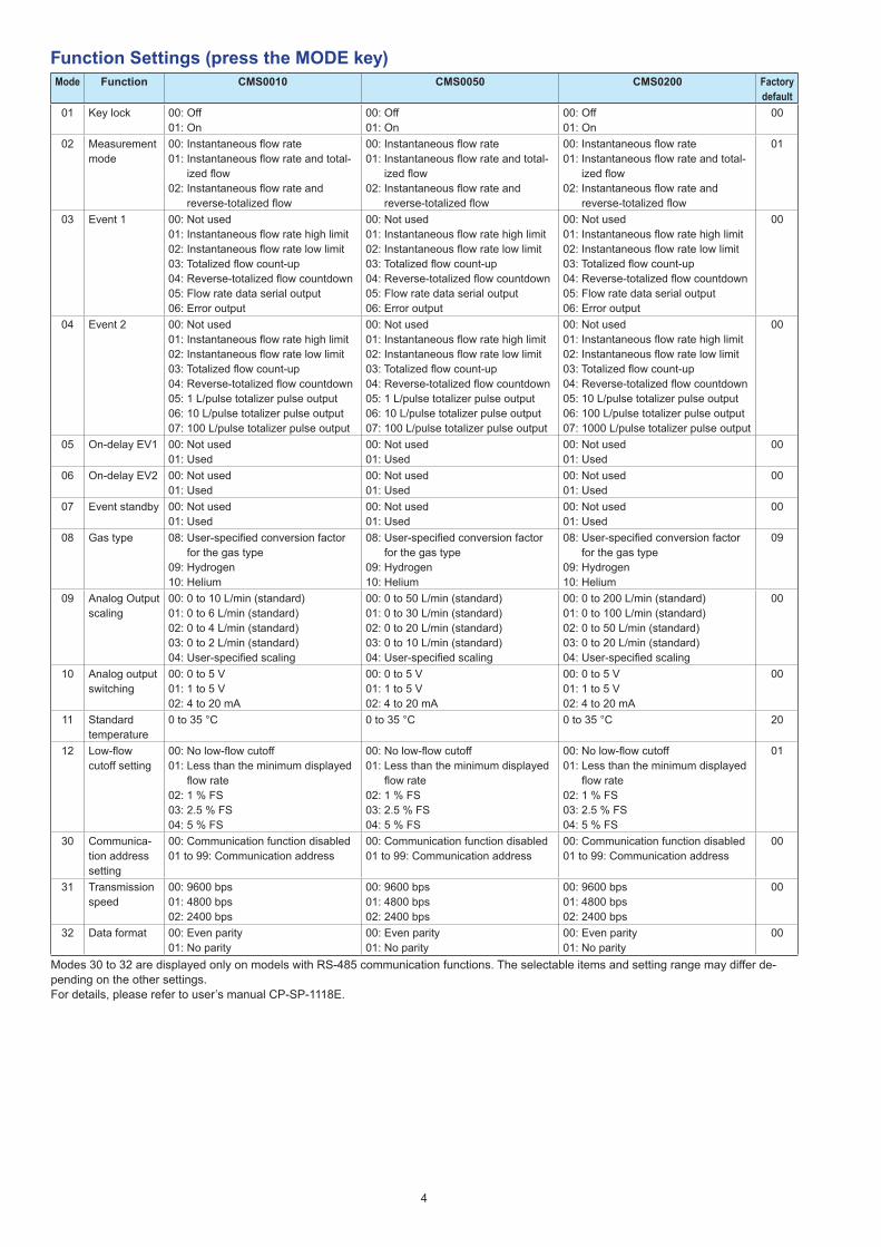
Function Settings (press the MODE key)Mode Function CMS0010 CMS0050 CMS0200 Factory
default01 Key lock 00: Off
01: On00: Off01: On
00: Off01: On
00
02 Measurement mode
00: Instantaneous flow rate01: Instantaneous flow rate and total-
ized flow02: Instantaneous flow rate and
reverse-totalized flow
00: Instantaneous flow rate01: Instantaneous flow rate and total-
ized flow02: Instantaneous flow rate and
reverse-totalized flow
00: Instantaneous flow rate01: Instantaneous flow rate and total-
ized flow02: Instantaneous flow rate and
reverse-totalized flow
01
03 Event 1 00: Not used01: Instantaneous flow rate high limit02: Instantaneous flow rate low limit03: Totalized flow count-up04: Reverse-totalized flow countdown05: Flow rate data serial output06: Error output
00: Not used01: Instantaneous flow rate high limit02: Instantaneous flow rate low limit03: Totalized flow count-up04: Reverse-totalized flow countdown05: Flow rate data serial output06: Error output
00: Not used01: Instantaneous flow rate high limit02: Instantaneous flow rate low limit03: Totalized flow count-up04: Reverse-totalized flow countdown05: Flow rate data serial output06: Error output
00
04 Event 2 00: Not used01: Instantaneous flow rate high limit02: Instantaneous flow rate low limit03: Totalized flow count-up04: Reverse-totalized flow countdown05: 1 L/pulse totalizer pulse output 06: 10 L/pulse totalizer pulse output07: 100 L/pulse totalizer pulse output
00: Not used01: Instantaneous flow rate high limit02: Instantaneous flow rate low limit03: Totalized flow count-up04: Reverse-totalized flow countdown05: 1 L/pulse totalizer pulse output06: 10 L/pulse totalizer pulse output07: 100 L/pulse totalizer pulse output
00: Not used01: Instantaneous flow rate high limit02: Instantaneous flow rate low limit03: Totalized flow count-up04: Reverse-totalized flow countdown05: 10 L/pulse totalizer pulse output06: 100 L/pulse totalizer pulse output07: 1000 L/pulse totalizer pulse output
00
05 On-delay EV1 00: Not used01: Used
00: Not used01: Used
00: Not used01: Used
00
06 On-delay EV2 00: Not used01: Used
00: Not used01: Used
00: Not used01: Used
00
07 Event standby 00: Not used01: Used
00: Not used01: Used
00: Not used01: Used
00
08 Gas type 08: User-specified conversion factor for the gas type
09: Hydrogen10: Helium
08: User-specified conversion factor for the gas type
09: Hydrogen10: Helium
08: User-specified conversion factor for the gas type
09: Hydrogen10: Helium
09
09 Analog Outputscaling
00: 0 to 10 L/min (standard)01: 0 to 6 L/min (standard)02: 0 to 4 L/min (standard)03: 0 to 2 L/min (standard)04: User-specified scaling
00: 0 to 50 L/min (standard)01: 0 to 30 L/min (standard)02: 0 to 20 L/min (standard)03: 0 to 10 L/min (standard)04: User-specified scaling
00: 0 to 200 L/min (standard)01: 0 to 100 L/min (standard)02: 0 to 50 L/min (standard)03: 0 to 20 L/min (standard)04: User-specified scaling
00
10 Analog output switching
00: 0 to 5 V01: 1 to 5 V02: 4 to 20 mA
00: 0 to 5 V01: 1 to 5 V02: 4 to 20 mA
00: 0 to 5 V01: 1 to 5 V02: 4 to 20 mA
00
11 Standard temperature
0 to 35 °C 0 to 35 °C 0 to 35 °C 20
12 Low-flow cutoff setting
00: No low-flow cutoff01: Less than the minimum displayed
flow rate02: 1 % FS03: 2.5 % FS04: 5 % FS
00: No low-flow cutoff01: Less than the minimum displayed
flow rate02: 1 % FS03: 2.5 % FS04: 5 % FS
00: No low-flow cutoff01: Less than the minimum displayed
flow rate02: 1 % FS03: 2.5 % FS04: 5 % FS
01
30 Communica-tion address setting
00: Communication function disabled01 to 99: Communication address
00: Communication function disabled01 to 99: Communication address
00: Communication function disabled01 to 99: Communication address
00
31 Transmission speed
00: 9600 bps01: 4800 bps02: 2400 bps
00: 9600 bps01: 4800 bps02: 2400 bps
00: 9600 bps01: 4800 bps02: 2400 bps
00
32 Data format 00: Even parity01: No parity
00: Even parity01: No parity
00: Even parity01: No parity
00
Modes 30 to 32 are displayed only on models with RS-485 communication functions. The selectable items and setting range may differ de-pending on the other settings.For details, please refer to user’s manual CP-SP-1118E.
4
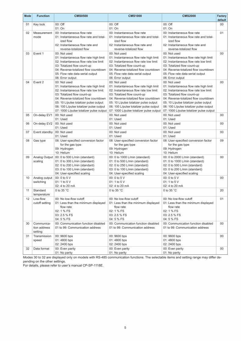
Mode Function CMS0500 CMS1000 CMS2000 Factory default
01 Key lock 00: Off01: On
00: Off01: On
00: Off01: On
00
02 Measurement mode
00: Instantaneous flow rate01: Instantaneous flow rate and total-
ized flow02: Instantaneous flow rate and
reverse-totalized flow
00: Instantaneous flow rate01: Instantaneous flow rate and total-
ized flow02: Instantaneous flow rate and
reverse-totalized flow
00: Instantaneous flow rate01: Instantaneous flow rate and total-
ized flow02: Instantaneous flow rate and
reverse-totalized flow
01
03 Event 1 00: Not used01: Instantaneous flow rate high limit02: Instantaneous flow rate low limit03: Totalized flow count-up04: Reverse-totalized flow countdown05: Flow rate data serial output06: Error output
00: Not used01: Instantaneous flow rate high limit02: Instantaneous flow rate low limit03: Totalized flow count-up04: Reverse-totalized flow countdown05: Flow rate data serial output06: Error output
00: Not used01: Instantaneous flow rate high limit02: Instantaneous flow rate low limit03: Totalized flow count-up04: Reverse-totalized flow countdown05: Flow rate data serial output06: Error output
00
04 Event 2 00: Not used01: Instantaneous flow rate high limit02: Instantaneous flow rate low limit03: Totalized flow count-up04: Reverse-totalized flow countdown05: 10 L/pulse totalizer pulse output06: 100 L/pulse totalizer pulse output07: 1000 L/pulse totalizer pulse output
00: Not used01: Instantaneous flow rate high limit02: Instantaneous flow rate low limit03: Totalized flow count-up04: Reverse-totalized flow countdown05: 10 L/pulse totalizer pulse output06: 100 L/pulse totalizer pulse output07: 1000 L/pulse totalizer pulse output
00: Not used01: Instantaneous flow rate high limit02: Instantaneous flow rate low limit03: Totalized flow count-up04: Reverse-totalized flow countdown05: 10 L/pulse totalizer pulse output06: 100 L/pulse totalizer pulse output07: 1000 L/pulse totalizer pulse output
00
05 On-delay EV1 00: Not used01: Used
00: Not used01: Used
00: Not used01: Used
00
06 On-delay EV2 00: Not used01: Used
00: Not used01: Used
00: Not used01: Used
00
07 Event standby 00: Not used01: Used
00: Not used01: Used
00: Not used01: Used
00
08 Gas type 08: User-specified conversion factor for the gas type
09: Hydrogen10: Helium
08: User-specified conversion factor for the gas type
09: Hydrogen10: Helium
08: User-specified conversion factor for the gas type
09: Hydrogen10: Helium
09
09 Analog Outputscaling
00: 0 to 500 L/min (standard)01: 0 to 300 L/min (standard)02: 0 to 200 L/min (standard)03: 0 to 100 L/min (standard)04: User-specified scaling
00: 0 to 1000 L/min (standard)01: 0 to 500 L/min (standard)02: 0 to 250 L/min (standard)03: 0 to 100 L/min (standard)04: User-specified scaling
00: 0 to 2000 L/min (standard)01: 0 to 1000 L/min (standard)02: 0 to 500 L/min (standard)03: 0 to 200 L/min (standard)04: User-specified scaling
00
10 Analog output switching
00: 0 to 5 V01: 1 to 5 V02: 4 to 20 mA
00: 0 to 5 V01: 1 to 5 V02: 4 to 20 mA
00: 0 to 5 V01: 1 to 5 V02: 4 to 20 mA
00
11 Standard temperature
0 to 35 °C 0 to 35 °C 0 to 35 °C 20
12 Low-flow cutoff setting
00: No low-flow cutoff01: Less than the minimum displayed
flow rate02: 1 % FS03: 2.5 % FS04: 5 % FS
00: No low-flow cutoff01: Less than the minimum displayed
flow rate02: 1 % FS03: 2.5 % FS04: 5 % FS
00: No low-flow cutoff01: Less than the minimum displayed
flow rate02: 1 % FS03: 2.5 % FS04: 5 % FS
01
30 Communica-tion address setting
00: Communication function disabled01 to 99: Communication address
00: Communication function disabled01 to 99: Communication address
00: Communication function disabled01 to 99: Communication address
00
31 Transmission speed
00: 9600 bps01: 4800 bps02: 2400 bps
00: 9600 bps01: 4800 bps02: 2400 bps
00: 9600 bps01: 4800 bps02: 2400 bps
00
32 Data format 00: Even parity01: No parity
00: Even parity01: No parity
00: Even parity01: No parity
00
Modes 30 to 32 are displayed only on models with RS-485 communication functions. The selectable items and setting range may differ de-pending on the other settings.For details, please refer to user’s manual CP-SP-1118E.
5
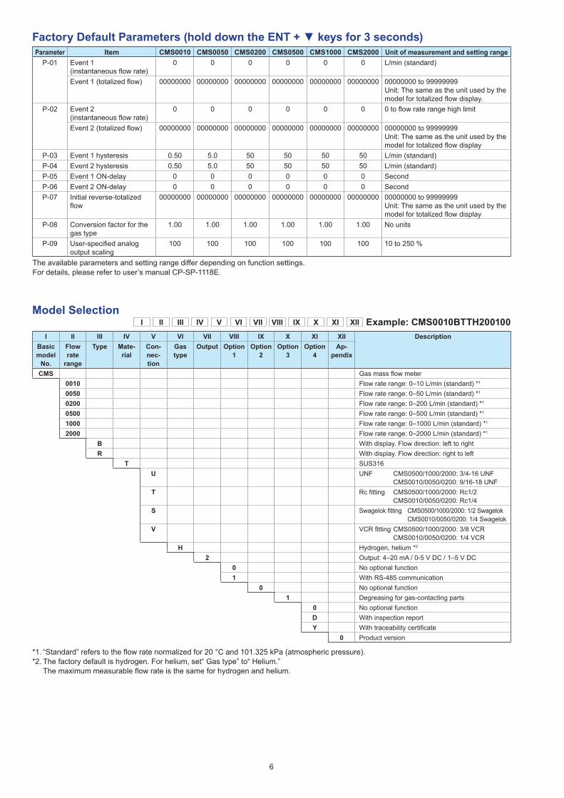
Factory Default Parameters (hold down the ENT + ▼ keys for 3 seconds)Parameter Item CMS0010 CMS0050 CMS0200 CMS0500 CMS1000 CMS2000 Unit of measurement and setting range
P-01 Event 1(instantaneous flow rate)
0 0 0 0 0 0 L/min (standard)
Event 1 (totalized flow) 00000000 00000000 00000000 00000000 00000000 00000000 00000000 to 99999999Unit: The same as the unit used by the model for totalized flow display.
P-02 Event 2(instantaneous flow rate)
0 0 0 0 0 0 0 to flow rate range high limit
Event 2 (totalized flow) 00000000 00000000 00000000 00000000 00000000 00000000 00000000 to 99999999Unit: The same as the unit used by the model for totalized flow display
P-03 Event 1 hysteresis 0.50 5.0 50 50 50 50 L/min (standard)P-04 Event 2 hysteresis 0.50 5.0 50 50 50 50 L/min (standard)P-05 Event 1 ON-delay 0 0 0 0 0 0 SecondP-06 Event 2 ON-delay 0 0 0 0 0 0 SecondP-07 Initial reverse-totalized
flow00000000 00000000 00000000 00000000 00000000 00000000 00000000 to 99999999
Unit: The same as the unit used by the model for totalized flow display
P-08 Conversion factor for the gas type
1.00 1.00 1.00 1.00 1.00 1.00 No units
P-09 User-specified analog output scaling
100 100 100 100 100 100 10 to 250 %
The available parameters and setting range differ depending on function settings.For details, please refer to user’s manual CP-SP-1118E.
Model Selection I II III IV V VI VII VIII IX X XI XII Example: CMS0010BTTH200100
I II III IV V VI VII VIII IX X XI XII DescriptionBasic model
No.
Flow rate
range
Type Mate-rial
Con-nec-tion
Gas type
Output Option1
Option2
Option3
Option4
Ap-pendix
CMS Gas mass flow meter0010 Flow rate range: 0–10 L/min (standard) *1
0050 Flow rate range: 0–50 L/min (standard) *1
0200 Flow rate range: 0–200 L/min (standard) *1
0500 Flow rate range: 0–500 L/min (standard) *1
1000 Flow rate range: 0–1000 L/min (standard) *1
2000 Flow rate range: 0–2000 L/min (standard) *1
B With display. Flow direction: left to rightR With display. Flow direction: right to left
T SUS316U UNF CMS0500/1000/2000: 3/4-16 UNF
CMS0010/0050/0200: 9/16-18 UNFT Rc fitting CMS0500/1000/2000: Rc1/2
CMS0010/0050/0200: Rc1/4S Swagelok fitting CMS0500/1000/2000: 1/2 Swagelok
CMS0010/0050/0200: 1/4 SwagelokV VCR fitting CMS0500/1000/2000: 3/8 VCR
CMS0010/0050/0200: 1/4 VCRH Hydrogen, helium *2
2 Output: 4–20 mA / 0-5 V DC / 1–5 V DC0 No optional function1 With RS-485 communication
0 No optional function1 Degreasing for gas-contacting parts
0 No optional functionD With inspection reportY With traceability certificate
0 Product version
*1. “Standard” refers to the flow rate normalized for 20 °C and 101.325 kPa (atmospheric pressure).*2. The factory default is hydrogen. For helium, set“ Gas type” to“ Helium.”
The maximum measurable flow rate is the same for hydrogen and helium.
6
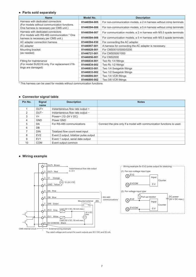
● Parts sold separatelyName Model No. Description
Harness with dedicated connectors(For models without communication functions. One harness is necessary per CMS unit.)
81446594-005 For non-communication models, a 2 m harness without crimp terminals
81446594-006 For non-communication models, a 5 m harness without crimp terminals
Harness with dedicated connectors(For models with RS-485 communication.* One harness is necessary per CMS unit.)
81446594-007 For communication models, a 2 m harness with M3.5 spade terminals
81446594-008 For communication models, a 5 m harness with M3.5 spade terminals
AC adapter connection harness 81446594-030 For connecting the AC adapterAC adapter 81446957-001 A harness for connecting the AC adapter is necessary.Mounting bracket(as needed)
81446628-001 For CMS0010/0050/020081446721-001 For CMS0500/100081446856-001 For CMS2000
Fitting for maintenance(For model SUS316 only. For replacement if fit-tings are damaged)
81446834-001 Two Rc 1/4 fittings81446834-002 Two Rc 1/2 fittings81446833-001 Two 1/4 Swagelok fittings81446833-002 Two 1/2 Swagelok fittings81446895-001 Two 1/4 VCR fittings81446895-002 Two 3/8 VCR fittings
* This harness can be used for models without communication functions.
● Connector signal tablePin No. Signal
nameDescription Notes
1 OUT+ Instantaneous flow rate output +2 OUT− Instantaneous flow rate output −3 V+ Power+ (12–24 V DC)4 GND Power GND5 DA For RS-485 communications Connect the pins only if a model with communication functions is used.6 DB7 DIN Totalized flow count reset input8 EV2 Event 2 output, totalizer pulse output9 EV1 Event 1 output, serial data output10 COM Event output common
● Wiring example
The rated voltage and current for event outputs are 30 V DC and 50 mA.
CMS internal circuit External wiring example
1 OUT+ Brown
Instantaneous flow rate output 0–5 V2 OUT– Red
3 V+ Orange
12–24 V DC4 GND Yellow
5
6
7 DIN Green
DA Pink
DB Blue
8 EV2 Gray Load (30 V DC, 50 mA max.)
Load (30 V DC, 50 mA max.)
30 V DC max.
Mounted external
9 EV1 White
10 EV COM/SG Black
SG
RS-485 communications
8 Input
0 V
EV2
Counter
DC power (30 V DC max.)
10EVCOM
Wiring example for EV2 pulse output for totalizing
8 Input
0 V
EV2Pull-up resistor
Counter
10EVCOM
For non-voltage input type(1)
For voltage input type(2)
7
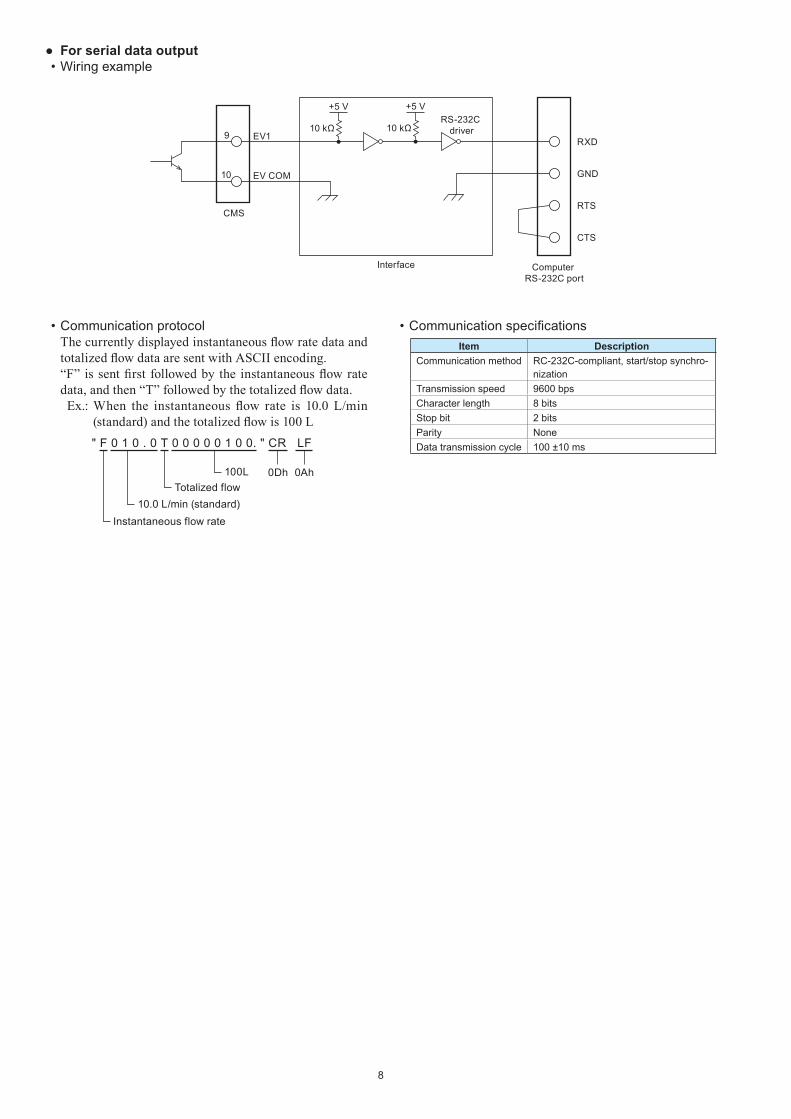
• Communication protocolThe currently displayed instantaneous flow rate data and totalized flow data are sent with ASCII encoding.“F” is sent first followed by the instantaneous flow rate data, and then “T” followed by the totalized flow data. Ex.: When the instantaneous flow rate is 10.0 L/min
(standard) and the totalized flow is 100 L" F 0 1 0 . 0 T 0 0 0 0 0 1 0 0. " CR LF
0Ah0Dh100LTotalized flow
Instantaneous flow rate10.0 L/min (standard)
• Communication specificationsItem Description
Communication method RC-232C-compliant, start/stop synchro-nization
Transmission speed 9600 bpsCharacter length 8 bitsStop bit 2 bitsParity NoneData transmission cycle 100 ±10 ms
● For serial data output• Wiring example
9 EV110 kΩ
RXD
+5 V
10 EV COM
CMS
GND
RTS
CTS
10 kΩRS-232C
driver
+5 V
Computer RS-232C port
Interface
8
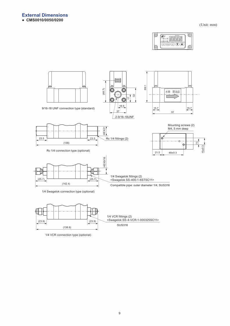
External Dimensions ● CMS0010/0050/0200
(Unit: mm)
9/16-18 UNF connection type (standard)91
15.7 15.7
69.1
水素 禁油品
Mounting screws (2)M4, 5 mm deep
21.5 48±0.3
7.5
15±0
.3
32
Rc 1/4 fittings (2)
Rc 1/4 connection type (optional)
23.523.5
(138)
HE
X21
(142.4)
1/4 Swagelok fittings (2)<Swagelok SS-400-1-6STSC11>
Compatible pipe: outer diameter 1/4, SUS316
(25.7) (25.7)
HE
X9/
16
1/4 Swagelok connection type (optional)
1/4 VCR fittings (2)<Swagelok SS-4-VCR-1-000325SC11>
SUS316(138.8)
(23.9) (23.9)
1/4 VCR connection type (optional)
37
2-9/16-18UNF
18.5
17
(48.
7)
X10L
L/min
EV2
EV1
ENTMODEDISP
Massflow
9
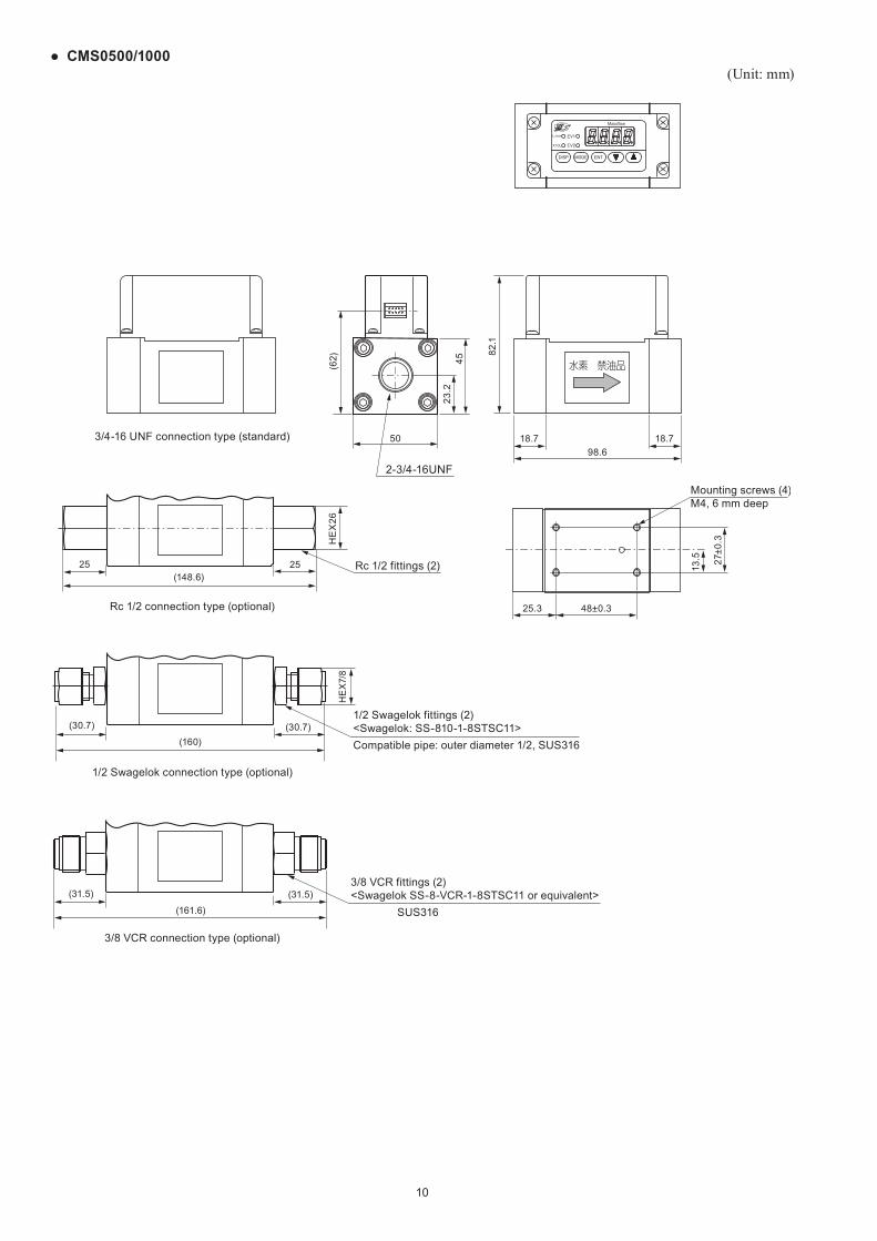
● CMS0500/1000(Unit: mm)
3/4-16 UNF connection type (standard)98.6
18.7 18.7
82.1
水素 禁油品
Rc 1/2 fittings (2)
Rc 1/2 connection type (optional)
2525(148.6)
HE
X26
(160)
1/2 Swagelok fittings (2)<Swagelok: SS-810-1-8STSC11>Compatible pipe: outer diameter 1/2, SUS316
(30.7) (30.7)
HE
X7/
8
1/2 Swagelok connection type (optional)
Mounting screws (4)M4, 6 mm deep
25.3 48±0.3
13.5 27
±0.3
2-3/4-16UNF
(62)
5023
.245
(161.6)
3/8 VCR fittings (2)<Swagelok SS-8-VCR-1-8STSC11 or equivalent>
SUS316
(31.5) (31.5)
3/8 VCR connection type (optional)
X10L
L/min
EV2
EV1
ENTMODEDISP
Massflow
10
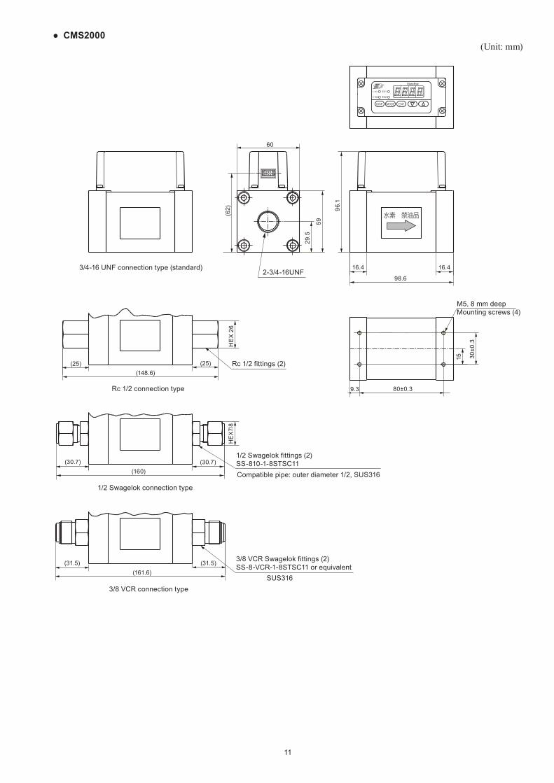
● CMS2000(Unit: mm)
(25) (25)
(31.5) (31.5)(161.6)
HE
X 2
6
(160)(30.7) (30.7)
(148.6)
98.6
16.416.4
96.1
29.5
59
(62)
60
9.3 80±0.3
30±0
.3
15
HE
X7/
8
Compatible pipe: outer diameter 1/2, SUS316
1/2 Swagelok fittings (2)SS-810-1-8STSC11
1/2 Swagelok connection type
Rc 1/2 connection type
Rc 1/2 fittings (2)
3/4-16 UNF connection type (standard)
M5, 8 mm deepMounting screws (4)
3/8 VCR connection type
3/8 VCR Swagelok fittings (2)SS-8-VCR-1-8STSC11 or equivalent
SUS316
2-3/4-16UNF
水素 禁油品
×10L
L/min
EV2
EV1
ENTMODEDISP
Massflow
11
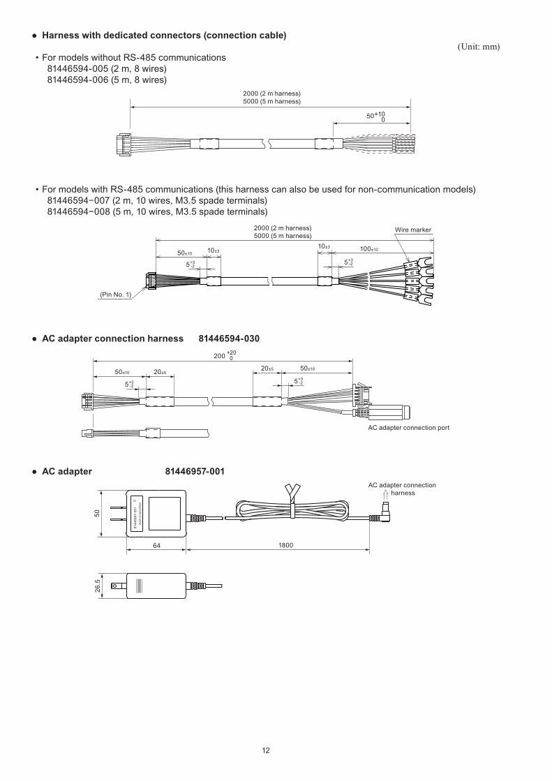
● Harness with dedicated connectors (connection cable)(Unit: mm)
• For models without RS-485 communications 81446594-005 (2 m, 8 wires) 81446594-006 (5 m, 8 wires)
50+100
2000 (2 m harness)5000 (5 m harness)
• For models with RS-485 communications (this harness can also be used for non-communication models) 81446594−007 (2 m, 10 wires, M3.5 spade terminals) 81446594−008 (5 m, 10 wires, M3.5 spade terminals)
50±10
5+3
-2
5+3
-2
10±310±3 100±10
(Pin No. 1)
Wire marker2000 (2 m harness)5000 (5 m harness)
● AC adapter connection harness 81446594-030
50±10
5+3
-2
200 +20 0
20±550±10
5+3
-2
20±5
AC adapter connection port
● AC adapter 81446957-001
8144
6957
-001
Azb
il C
orpo
ratio
n
5026
.5
64 1800
AC adapter connection harness
12
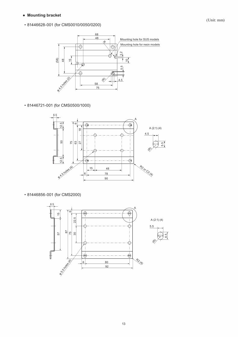
● Mounting bracket(Unit: mm)
• 81446628-001 (for CMS0010/0050/0200)
Mounting hole for SUS models
Mounting hole for resin models
68
15 10
3.2
5.5
48(58)
R
(R)
48
5875
4.5
φ 4.5 h
oles (
2)
• 81446721-001 (for CMS0500/1000)
5.550
12.5
12.5
18276375
6
15 48
6 78
90
4.5
A
A (2:1) (4)
6.5
φ 4.5 holes (4) R2 or C2 (4)
(R)
• 81446856-001 (for CMS2000)
6.5
5.5
A
A (2:1) (4)
926 80
R2 (4)
22.5
3075876
(R)
5715
6.5
φ 5.
5 ho
les (4
)
13
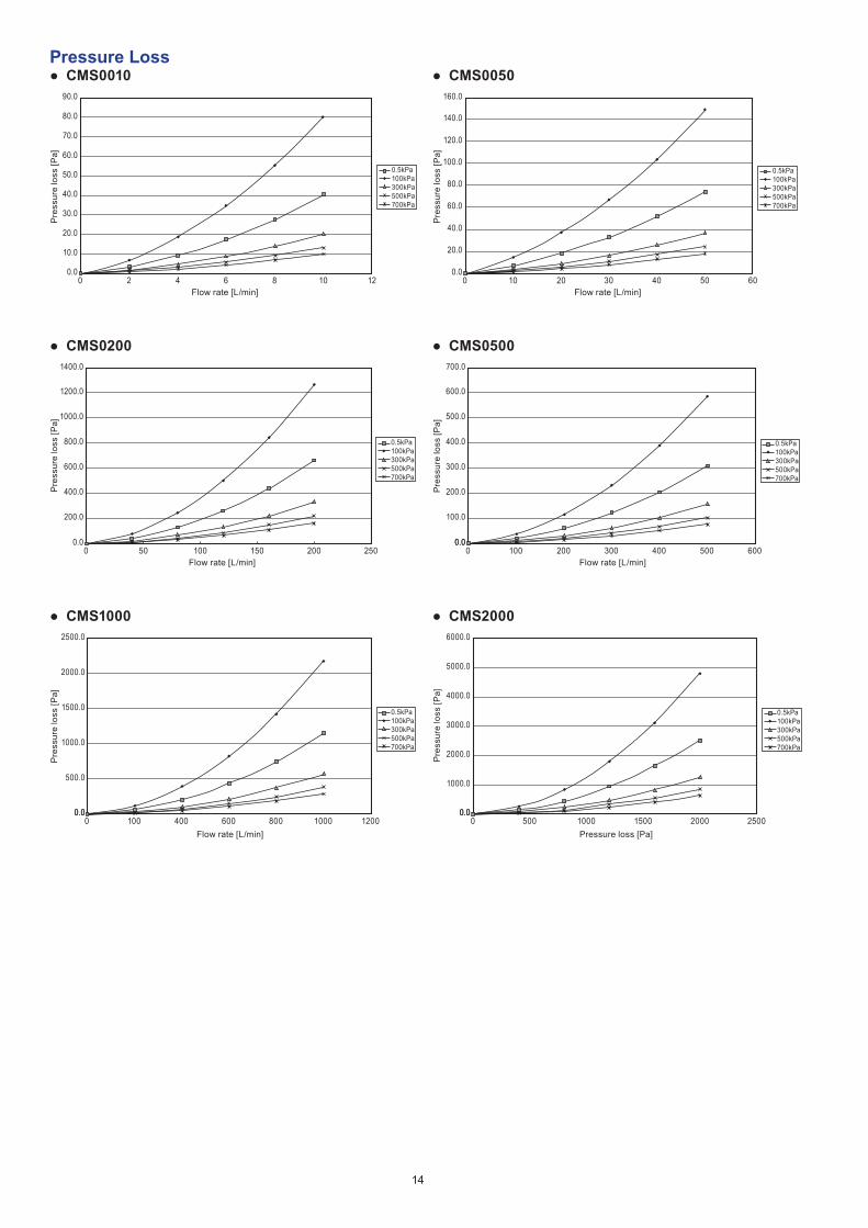
Pressure Loss ● CMS0010
0.0
10.0
20.0
30.0
40.0
50.0
60.0
70.0
80.0
90.0
0 2 4 6 8 10 12Flow rate [L/min]
Pre
ssur
e lo
ss [P
a]
0.5kPa100kPa300kPa500kPa700kPa
● CMS0200
0.5kPa100kPa300kPa500kPa700kPa
0.0
200.0
400.0
600.0
800.0
1000.0
1200.0
1400.0
0 50 100 150 200 250Flow rate [L/min]
Pre
ssur
e lo
ss [P
a]
● CMS1000
0.5kPa100kPa300kPa500kPa700kPa
0.0
500.0
1000.0
1500.0
2000.0
2500.0
0.00 100 400 600 800 1000 1200
Flow rate [L/min]
Pre
ssur
e lo
ss [P
a]
● CMS0050
0.5kPa100kPa300kPa500kPa700kPa
0.0
20.0
40.0
60.0
80.0
100.0
120.0
140.0
160.0
0 10 20 30 40 50 60Flow rate [L/min]
Pre
ssur
e lo
ss [P
a]
● CMS0500
0.5kPa100kPa300kPa500kPa700kPa
0.0
100.0
200.0
300.0
400.0
500.0
600.0
700.0
0.00 100 200 300 400 500 600
Flow rate [L/min]
Pre
ssur
e lo
ss [P
a]
● CMS2000
0.5kPa100kPa300kPa500kPa700kPa
0.0
1000.0
2000.0
3000.0
4000.0
5000.0
6000.0
0.00 500 1000 1500 2000 2500
Pressure loss [Pa]
Pre
ssur
e lo
ss [P
a]
14

15

1st edition: Nov. 2017
(13)
Please read “Terms and Conditions” from the following URL before ordering and use.
http://www.azbil.com/products/factory/order.html
1-12-2 Kawana, FujisawaKanagawa 251-8522 Japan
http://www.azbil.com/
Specifications are subject to change without notice.
No part of this publication may be reproduced or duplicated without the prior written permission of Azbil Corporation.16


![Hydrogen/helium gas model (SUS316) VCR or equiv. (CMS0500/1000/2000) Hydrogen, helium [Note 5] 4-20mAdc / 0-5Vdc / 1-5Vdc selectable (None) RS-485 communications (None) Gas-contacting](https://img.pdfslide.net/doc/110x75/5bb2480c09d3f249438c4f21/hydrogenhelium-gas-model-sus316-quot-vcr-or-equiv-cms050010002000-hydrogen.jpg)