Embed Size (px)
Citation preview
Annual Report 2010/11
Innovation Funding Incentive
Gas Transmission R&D Programme Detailed Reports
280
National Grid Gas Transmission R&D Programme Detailed Report During the financial year 2010/2011 National Grid Gas (NGG) Transmission utilised 98% of the Innovation Funding Incentive across a number of programme areas. These programme areas and their associated projects are indexed below and the progress reports can be seen over the next few pages. The report has been structured to show the research project and the area of research they relate to broadly following the asset types that National Grid has on the NTS.
Contents
National Grid Gas Transmission R&D Programme Detailed Report ....................... 280 Contents ....................................................................................................................... 280 Network......................................................................................................................... 282
Improving Understanding of Future Network Requirements....................................................282 ENA Gas Future Scenarios Project ...................................................................................................... 282 Demand Side Modelling ........................................................................................................................ 284 Enhanced Probabilistic Supply Modelling ............................................................................................. 286 Asset Management and Performance of Energy Systems................................................................... 288
Entry points .................................................................................................................. 291 Improving the Management of Contamination at Entry points .................................................291
External Contamination Detection and Measurement at Entry Points.................................................. 291 Pipelines ....................................................................................................................... 294
Pipeline Route surveys ...........................................................................................................294 Combined Geophysics Tool for Pipelines Routeing & Risk Assessment ............................................. 294
Third party inference...............................................................................................................296 Pipeline Impact Detection System ........................................................................................................ 296 Third Party Work Surveillance............................................................................................................... 298 Automatic Risk-based Handling of Plant Enquiries .............................................................................. 300
Road Crossing Maintenance...................................................................................................302 Optimisation of Integrity Management at Sleeved Crossings ............................................................... 302
Excavations ............................................................................................................................304 MTM (Magnetic Tomography Method) Pipeline Inspection System: Evaluation & Validation.............. 304 Development of AC Over Line Survey System..................................................................................... 308
Re-use of Gas Assets.............................................................................................................312 Research into Requirements for Gaseous Phase CO2 Transmission ................................................. 312
Above Ground Facilities and Pipelines...................................................................... 324 Risk Assessment Methodologies ............................................................................................324
Risk Assessment Methodologies for Pipelines and AGIs ..................................................................... 324 Ageing valve research ............................................................................................................328
Plumley Block Valve Removal .............................................................................................................. 328 Ball Valve Sealant Testing .................................................................................................................... 330 Ledeen Valve Actuator Tie Rod Condition............................................................................................ 332
Methane Emissions ................................................................................................................335 Alternatives to Venting from the NTS Gas Transmission System ........................................................ 335
Reducing risks ........................................................................................................................339 Geotechnics .......................................................................................................................................... 339 Development of improved suction pipework filtration methods for compressors.................................. 341
Above ground Facilities .............................................................................................. 343 Reducing Risk ........................................................................................................................343
Installation of IRIS separators [at Carnforth Compressor Station]........................................................ 343 Advances in Compressor Pipework Vibration Monitoring and Effectiveness of Instrument Stabbing Encapsulation to Reduce Vibration Response...................................................................................... 345
Environmental Impact .............................................................................................................348 Environmental Study for Future Above Ground Facility Developments ............................................... 348
Above Ground Installation Maintenance .................................................................................353 AGI Paint Systems ................................................................................................................................ 353 Pit Wall Transitions Inspection Technologies ....................................................................................... 356 Detection & Management of Corrosion on Above Ground Insulated Pipework and Pipe Supports ..... 358

281
Metering........................................................................................................................ 360 Meter assets management .....................................................................................................360
Development of FWACV Capability for New Gas Chromatograph DANINT Software......................... 360 AGI Meter Enhancement and Boiler capacity study ............................................................................. 363
International Research memberships ........................................................................ 366 Leveraged International Research Programmes for Gas Pipelines and Above Ground Facilities ....... 366
282
Network
Improving Understanding of Future Network Requirements
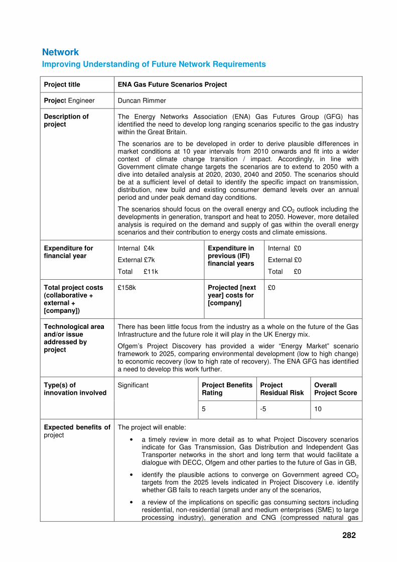
Project title ENA Gas Future Scenarios Project
Project Engineer Duncan Rimmer
Description of project
The Energy Networks Association (ENA) Gas Futures Group (GFG) has identified the need to develop long ranging scenarios specific to the gas industry within the Great Britain.
The scenarios are to be developed in order to derive plausible differences in market conditions at 10 year intervals from 2010 onwards and fit into a wider context of climate change transition / impact. Accordingly, in line with Government climate change targets the scenarios are to extend to 2050 with a dive into detailed analysis at 2020, 2030, 2040 and 2050. The scenarios should be at a sufficient level of detail to identify the specific impact on transmission, distribution, new build and existing consumer demand levels over an annual period and under peak demand day conditions.
The scenarios should focus on the overall energy and CO2 outlook including the developments in generation, transport and heat to 2050. However, more detailed analysis is required on the demand and supply of gas within the overall energy scenarios and their contribution to energy costs and climate emissions.
Expenditure for financial year
Internal £4k
External £7k
Total £11k
Expenditure in previous (IFI) financial years
Internal £0
External £0
Total £0
Total project costs (collaborative + external + [company])
£158k Projected [next year] costs for [company]
£0
Technological area and/or issue addressed by project
There has been little focus from the industry as a whole on the future of the Gas Infrastructure and the future role it will play in the UK Energy mix.
Ofgem’s Project Discovery has provided a wider “Energy Market” scenario framework to 2025, comparing environmental development (low to high change) to economic recovery (low to high rate of recovery). The ENA GFG has identified a need to develop this work further.
Project Benefits Rating
Project Residual Risk
Overall Project Score
Type(s) of innovation involved
Significant
5 -5 10
Expected benefits of project
The project will enable:
• a timely review in more detail as to what Project Discovery scenarios indicate for Gas Transmission, Gas Distribution and Independent Gas Transporter networks in the short and long term that would facilitate a dialogue with DECC, Ofgem and other parties to the future of Gas in GB,
• identify the plausible actions to converge on Government agreed CO2 targets from the 2025 levels indicated in Project Discovery i.e. identify whether GB fails to reach targets under any of the scenarios,
• a review of the implications on specific gas consuming sectors including residential, non-residential (small and medium enterprises (SME) to large processing industry), generation and CNG (compressed natural gas

283
transport)
• a review of the impact of Carbon Capture and Storage (on industry to CCS networks, and Generation), bio-methane injection and other supply sources,
• an evaluation of the full economic impact (total investment and annual costs to operate) and the average cost per consumer (for gas and total energy as a comparison between scenarios),
• the identification of longer term risks and opportunities through the use of appropriate stress tests,
• a review of the implications of how particular Government policies could influence the scenarios, the impact on CO2 emissions and costs i.e. Carbon Neutral Homes impact on new housing connections to gas from 2016, 2019 proposals for Carbon Neutral Commercial properties, revised Building Regulations etc.
Expected timescale of project
1 year Duration of benefit once achieved
Ongoing future scenario planning.
Probability of success
90% Project NPV = (PV benefits – PV costs) x probability of success
-£4k
Potential for achieving expected benefits
High given Redpoint’s reputation, the reports high profile launch and tailored briefing for DECC and GEMA the key messages and cost implications have been successfully communicated and explained to the key stakeholders. This communication has been reinforced with additional briefings with DECC’s 2050 Pathways team.
Project progress
[Year to End of March 2011]
Project completed on time in November 2010 with final report and presentation material provided. In addition to DECC and GEMA briefing sessions, a high profile launch in London took place with speakers including Charles Hendry (Minister of State for Energy and Climate Change) and was attended by many key industry stakeholders. Subsequently the key messages have also been communicated as part of National Grid’s “Transporting Britain’s Energy” consultation process.
In January 2011 the model was handed over and a training session took place with a view to networks companies using it to update the analysis over time.
Collaborative partners
Total cost of project: £158,000
National Grid Gas Distribution 44.96%
Northern Gas Networks 12.8%
Scotia Gas Networks 25.59%
Wales & West Utilities 12.1%
Inexus 1.93%
National Grid Transmission 2.63%
R&D provider Redpoint

284
Project title Demand Side Modelling
Project Engineer Chandima Dutton
Description of project
The primary aim of the project is to develop risk models that may be used to inform long-term planning decisions made by National Grid Gas Transmission. The models are also anticipated to provide information for shorter-term operational decision-making.
Expenditure for financial year
Internal £5k
External £27k
Total £33k
Expenditure in previous (IFI) financial years
Internal £2k
External £102k
Total £104k
Total project costs (collaborative + external + NG)
£142k Projected 2011/12 costs for NG
£0
Technological area and/or issue addressed by project
The project will involve the identification and development of:
• A gas flow monitoring process
• A risk-analysis methodology (e.g. utilising a Monte Carlo approach)
It should be possible for National Grid to update the models easily on an ongoing basis in order that the risk models may be embedded within the planning process. The models may be shared with Ofgem to support discussions on investment plans.
Project Benefits Rating
Project Residual Risk
Overall Project Score
Type(s) of innovation involved
Incremental
17 2 15
Expected benefits of project
The primary benefit for the work is ensuring that security of supply is maintained by the integrated gas Transmission and Distribution networks (DNs), as new arrangements come into play. However, through better knowledge of how the DN operators will change their behaviour with the new arrangements, National Grid Transmission would also hope to introduce more efficiency into their investment plans and operational planning. For example, every 1km of new pipeline that can be avoided will result in a saving of around £1m-£2m.
Expected timescale of project
2 year Duration of benefit once achieved
5 years
Probability of success
60% Project NPV = (PV benefits – PV costs) x probability of success
£108k
Potential for achieving expected benefits
For the report into DN planning and design the potential for achieving the expected benefits is arguably 100%, as the report has now been issued to DNs for their comment. Any, or even no, response from them will confirm the details of the report or otherwise.
The use of the Demand Side Model is less certain as it relies on getting more data to increase the number of DNs it covers (which may be problematic), its integration into the NGG processes (which is within NGG’s control) and discussion of the results with the wider industry including Ofgem and the DNs (which may be on-going).
Project progress
The primary aim of the project was to develop risk models that may be used to inform long term planning decisions. The Excel-based models developed provide information for shorter term operational decision-making using Monte Carlo

285
[Year to End of March 2011]
Simulation to understand the offtake behaviour for a local distribution zone (LDZ).
The models are based on a large amount of data received from National Grid (e.g. actual offtake flows, calorific value (CV) and other demand data) and have been created in a manner to make it possible for National Grid to easily update them on an ongoing basis. A basic user interface only has been developed (together with a User Guide), suitable for an expert user to input new data as needed. The risk models may then be embedded within National Grid’s planning process.
The models constructed and results reported were for the East Midlands (EM) LDZ only, although the same techniques and models could equally be applied to any LDZ given appropriate data.
A report (10389 Demand Side Modelling - Model Run Summary) provides details of and results from a number of runs of the Demand Side Modelling Daily Monte Carlo model. The runs cover a set of what if analyses designed to illustrate the effect on peak demand, average demand and diurnal volume of variations in the input parameters, specifically load growth and global warming. The report assesses the effects of these variations in the input parameters, both in isolation and in conjunction, when they operate at a number of different levels (e.g. none, minimum, expected, maximum).
A final report (GL ND Report 9989 for NG NTS Demand Side Modelling Design of Distribution Systems V1_0) has been developed to explain the DN planning processes, the high level assumptions that the DNs use and the risks to the NTS as a result (as understood by GL).
The report details the basis for the transient analysis required to model high pressure (HP) Distribution systems, the sources of data used, the constraints which apply to the design and the overall modelling processes for design and operation of the HP Distribution system. The report goes on to describe the options available to a DN for assessing the diurnal storage required and the DNs options for obtaining that storage. The interplay of the DNs’ options between supply, reinforcement, and demand considerations is discussed. The whole detail of the report is summarised through a long term planning and an operational planning risk assessments. These outline the potential sources of risk to the NTS of errors in levels of gas take requested by the DNs in their long term planning and day-to-day operation.
The report has subsequently circulated to the DNs for their feedback. It is hoped that the report will prompt discussion and eventual common understanding of the processes and risks involved in the collective planning of the system.
The report may also form the basis of a further project to develop training for NTS staff to aid in the understanding of DN planning.
Collaborative partners
None
R&D provider GL Noble Denton
286
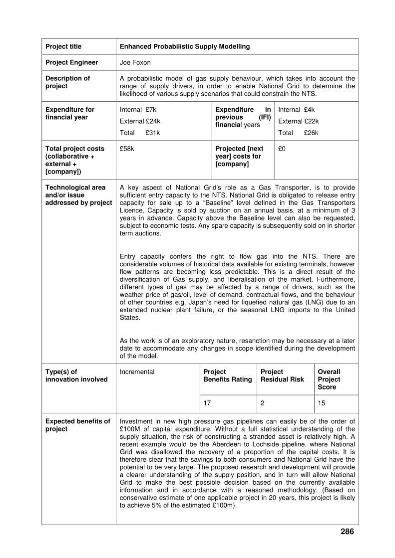
Project title Enhanced Probabilistic Supply Modelling
Project Engineer Joe Foxon
Description of project
A probabilistic model of gas supply behaviour, which takes into account the range of supply drivers, in order to enable National Grid to determine the likelihood of various supply scenarios that could constrain the NTS.
Expenditure for financial year
Internal £7k
External £24k
Total £31k
Expenditure in previous (IFI) financial years
Internal £4k
External £22k
Total £26k
Total project costs (collaborative + external + [company])
£58k Projected [next year] costs for [company]
£0
Technological area and/or issue addressed by project
A key aspect of National Grid’s role as a Gas Transporter, is to provide sufficient entry capacity to the NTS. National Grid is obligated to release entry capacity for sale up to a “Baseline” level defined in the Gas Transporters Licence. Capacity is sold by auction on an annual basis, at a minimum of 3 years in advance. Capacity above the Baseline level can also be requested, subject to economic tests. Any spare capacity is subsequently sold on in shorter term auctions.
Entry capacity confers the right to flow gas into the NTS. There are considerable volumes of historical data available for existing terminals, however flow patterns are becoming less predictable. This is a direct result of the diversification of Gas supply, and liberalisation of the market. Furthermore, different types of gas may be affected by a range of drivers, such as the weather price of gas/oil, level of demand, contractual flows, and the behaviour of other countries e.g. Japan’s need for liquefied natural gas (LNG) due to an extended nuclear plant failure, or the seasonal LNG imports to the United States.
As the work is of an exploratory nature, resanction may be necessary at a later date to accommodate any changes in scope identified during the development of the model.
Project Benefits Rating
Project Residual Risk
Overall Project Score
Type(s) of innovation involved
Incremental
17 2 15
Expected benefits of project
Investment in new high pressure gas pipelines can easily be of the order of £100M of capital expenditure. Without a full statistical understanding of the supply situation, the risk of constructing a stranded asset is relatively high. A recent example would be the Aberdeen to Lochside pipeline, where National Grid was disallowed the recovery of a proportion of the capital costs. It is therefore clear that the savings to both consumers and National Grid have the potential to be very large. The proposed research and development will provide a clearer understanding of the supply position, and in turn will allow National Grid to make the best possible decision based on the currently available information and in accordance with a reasoned methodology. (Based on conservative estimate of one applicable project in 20 years, this project is likely to achieve 5% of the estimated £100m).
287
Expected timescale of project
2 years Duration of benefit once achieved
5 years
Probability of success
60% Project NPV = (PV benefits – PV costs) x probability of success
£1,020k
Potential for achieving expected benefits
While the project has not yet achieved most of the expected benefits, this is due to the complex nature of the problem and the innovative and unique approach to modelling being developed. There is still confidence that the project has the potential to bring the expected benefits however further work (and funding) will be required to do this.
Project progress
[Year to End of March 2011]
The project has now come to the end of sanctioned funding. This initial phase of the project has allowed Warwick University to gain the required knowledge of the gas industry and National Grid’s current procedures for supply modelling and begin to investigate the supply situation. Warwick University have produced a report detailing their findings which was presented to National Grid on 21st January. The Report and presentation were very well received and have generated some useful discussion around the future direction of the project. Network Operations in particular saw a potential benefit for a system operator incentives application of the model. As part of the report Warwick University suggested several new ways of visualising the supply distribution, some of which have already been very useful as part of the RIIO process. Warwick University have also provided a tool (for creating ternary diagrams) which can be used as part of the planning process to support the development of supply scenarios used for investment analysis. Follow up meetings have taken place where Warwick University have presented several suggestions on how the current work could be developed. We are currently exploring how the work can be turned into a useable methodology for NTS investment planning. Warwick University has proposed to present the Dynamic Linear Modelling part of their work at a statistical conference in Miami with a view to publication,
Collaborative partners
None
R&D provider Warwick University
288
Project title Asset Management and Performance of Energy Systems
Project Engineer Jenny Cooper
Description of project
This project is a collaboration between 6 universities and 10 industrialists (including National Grid). GLND are interacting with the universities on the gas transmission aspects, such as the modelling of the gas network and the interaction between gas and electricity network models. The overall project is addressing the following strategic key issues:
• The need to maintain reliable energy supply
• Ageing plant
• Changing requirements (environment)
• Renewable and distributed power generation
• Reduced skills base
The “dash for gas” has led to a significant portion of the UK’s electricity generating capacity being supplied by gas. This led to concern about the security of supply for the UK, taking into account the interactions between the gas and electricity transmission systems.
Expenditure for financial year
Internal £4k
External £13k
Total £17k
Expenditure in previous (IFI) financial years
Internal £6k
External £91k
Total £97k
Total project costs (collaborative + external + [company])
£2,914k Projected [next year] costs for [company]
£0
Technological area and/or issue addressed by project
The convergence of vectors for energy generation, supply and use is causing increasing interplay between gas and electricity networks. This interaction is being modelled through close cooperation between GLND and Edinburgh University.
The aim is to create an integrated model of both transmission systems and to run scenarios to understand the performance of the overall system under normal and stressed conditions. The concern is to identify if it is possible for a commonly experienced failure on one system (such as a gas network compressor trip) to lead to a catastrophic failure of the both systems.
Project Benefits Rating
Project Residual Risk
Overall Project Score
Type(s) of innovation involved
Incremental
7 0 7
Expected benefits of project
This project aims to improve the understanding of the impact on Gas and Electricity networks of current and future trends in energy supply and energy use. This will allow improved decisions to be made on the management of assets, and if a demand side approach to energy management can be adopted, it should allow CAPEX and OPEX to be reduced on energy transmission infrastructure. This is a research project with potential unspecified benefits arising in future years as we move to a low carbon economy.
As the dependence on natural gas for electricity generation in the UK grows, it is becoming increasingly difficult to decouple the security of the gas supply from the security of the electricity supply. As a result, the planning and operation of the transmission network infrastructures can no longer be treated separately and the challenge now faced by industry participants is the necessary harmonisation of the separate networks. This activity will provide an in-depth combined security
289
analysis of the gas and electricity transmission networks in the UK to enhance the limited work that has been done in this area. It will involve the production of a fully-automated combined electricity and gas network model, assessing the extent of the networks’ vulnerability and interdependence and will also address the potential for integrated operation to enhance fuel delivery and security.
Expected timescale of project
2 years Duration of benefit once achieved
5 years
Probability of success
60% Project NPV = (PV benefits – PV costs) x probability of success
£-97k
Potential for achieving expected benefits
GL Noble Denton has a long established track record in network simulation software development for energy and utility networks. The EPSRC consortium is well supported and becoming more experienced in modelling. However, the combination of the two types of transmission system into one overall model will present numerous challenges.
Project progress
[Year to End of March 2011]
Through the research presented in this study the operational challenges associated with the expected growth in wind power generation by 2020 on both the UK electricity and gas transmission systems have been shown to be multifaceted. Specific attention was given to the modelling technique of the gas network and how full transient network modelling is required to assess these operational impacts. It was also found that the expected change in behaviour of CCGT units will coincide with new supply patterns emerging on the NTS as our indigenous supply of gas runs out and a growing reliance on foreign sources becomes more apparent. This means that specific areas of the gas network that need to be reinforced to cope with the increased requirement for flexibility at gas-fired power stations are difficult to pinpoint. Therefore the requirement for fast-response storage and constraint management services on the gas network has been affirmed in this study and the current security codes by which both the UK electricity and gas networks are designed have been shown to be inadequate in their present form.
GL Noble Denton originally provided Edinburgh with Gas Solver, the software engine of the SynerGEE analysis tool. This would be most easily integrated with other software in use on the project. However, to facilitate some of the transient analysis requirements, the software was replaced by alternative Falcon software, which was enhanced to enable multiple analyses to be carried out at varying conditions.
In addition to providing and supporting the software, GL Noble Denton also provided Edinburgh with an understanding of the approaches used in the design and operation of the NTS for gas through a series of meeting/workshops and day to day support as required. The aim of this aspect of the work was to assist Edinburgh in understanding the basis for how the integrated modelling should be conducted from a gas point of view and the conditions which should be considered as scenarios to be analysed.
GL Noble Denton also facilitated communications between Edinburgh and National Grid NTS, who agreed to provide Edinburgh with the latest model and details of the gas NTS for use in the integrated model. GL Noble Denton provided a gas network perspective at a number of Supergen project meetings, which were otherwise heavily weighted towards electricity.
Potential Further Work
The Supergen project addressed the interactions between gas and electricity systems at a national transmission level, considering generating capacity that is connected directly to the gas NTS. However, it is expected that embedded generation from renewable sources and unconventional gas will increase in the future, leading to significant gas / electricity interactions within the distribution systems and from the distribution systems up to transmission networks. The issues which arise under this scenario may be more localised, but there may still

290
be significant security of supply issues for particular localities.
The relationship between the high pressure gas distribution system and the national gas transmission system is critical both commercially and operationally. Embedded electricity generation and increased bio-methane input within the distribution systems will add to the difficulties in assessing design and operational requirements for such networks. This will put increased emphasis on the design, commercial and operational requirements for the interface between gas transmission and distribution. An investigation into the potential impacts of new and developing energy sources on these interface relationships could develop new ways of optimising the design and operation of gas and electricity networks.
Collaborative partners
Supergen V Amperes consortium and specifically Edinburgh University.
R&D provider GL Industrial Services (UK) Ltd
291
Entry points
Improving the Management of Contamination at Entry points
Project title External Contamination Detection and Measurement at Entry Points
Project Engineer John Harris
Description of project
This project will provide recommendations on the device, or array of devices, that would be required to detect liquid contamination at the entry points to the NTS gas transmission system. The project will also evaluate the capability of such devices to provide quantitative measurements, initially targeting “order of magnitude” as a level of uncertainty.
Expenditure for financial year
Internal £4k
External £28k
Total £33k
Expenditure in previous (IFI) financial years
Internal £8k
External £698k
Total £707k
Total project costs (collaborative + ext + NG)
£975k Projected 2011/12 costs for NG
£235k
Technological area and/or issue addressed by project
Compliance with GS(M)R and National Grid network entry agreements with regard to “solid or liquid material that may interfere with the integrity or operation of pipes or any gas appliance within the meaning of regulation 2(1) of the Gas Safety (Installation and Use) Regulations 1998 that a consumer could reasonably be expected to operate”.
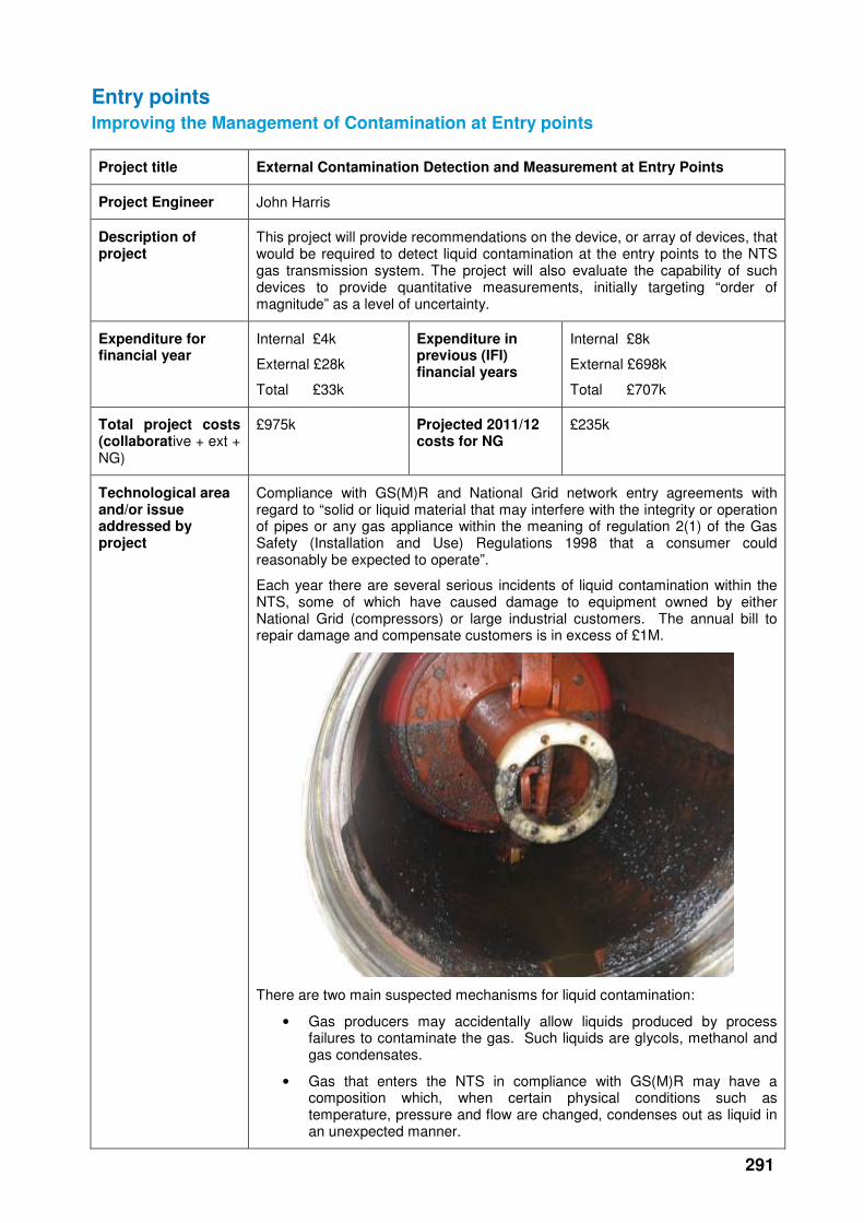
Each year there are several serious incidents of liquid contamination within the NTS, some of which have caused damage to equipment owned by either National Grid (compressors) or large industrial customers. The annual bill to repair damage and compensate customers is in excess of £1M.
There are two main suspected mechanisms for liquid contamination:
• Gas producers may accidentally allow liquids produced by process failures to contaminate the gas. Such liquids are glycols, methanol and gas condensates.
• Gas that enters the NTS in compliance with GS(M)R may have a composition which, when certain physical conditions such as temperature, pressure and flow are changed, condenses out as liquid in an unexpected manner.
292
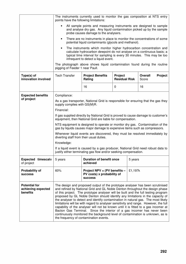
The instruments currently used to monitor the gas composition at NTS entry points have the following limitations:
• All sample points and measuring instruments are designed to sample and analyse dry gas. Any liquid contamination picked up by the sample probe causes damage to the analysers.
• There are no instruments in place to monitor the concentrations of some potential liquid contaminants (glycols and methanol).
• The instruments which monitor higher hydrocarbon concentration and calculate hydrocarbon dewpoint do not analyse on a continuous basis; a typical time interval for sampling is every 30 minutes. This may be too infrequent to detect a liquid event.
The photograph above shows liquid contamination found during the routine pigging of Feeder 1 near Paull.
Project Benefits Rating
Project Residual Risk
Overall Project Score
Type(s) of innovation involved
Tech Transfer
16 0 16
Expected benefits of project
Compliance:
As a gas transporter, National Grid is responsible for ensuring that the gas they supply complies with GS(M)R.
Financial:
If gas supplied directly by National Grid is proved to cause damage to customer’s equipment, then National Grid are liable for compensation.
NTS equipment is designed to operate or monitor dry gas. Contamination of the gas by liquids causes major damage to expensive items such as compressors.
Whenever liquid events are discovered, they must be resolved immediately by diverting staff from their usual duties.
Knowledge:
If a liquid event is caused by a gas producer, National Grid need robust data to justify either terminating gas flow and/or seeking compensation.
Expected timescale of project
5 years Duration of benefit once achieved
5 years
Probability of success
60% Project NPV = (PV benefits – PV costs) x probability of success
£1,197k
Potential for achieving expected benefits
The design and proposed output of the prototype analyser has been scrutinised and refined by National Grid and GL Noble Denton throughout the design phase of this project. The prototype analyser will be built and the full testing program proposed by GL Noble Denton should identify any limitations in the capacity of the analyser to detect and identify contamination in natural gas. The most likely limitations will be with regard to analyser sensitivity and range. However, the full capability of the analyser will not be known until it is fitted to a gas incomer at Bacton Gas Terminal. Since the interior of a gas incomer has never been continuously monitored the background level of contamination is unknown, as is the frequency of contamination events.
293
Project progress
[Year to End of March 2011]
The Project Team:
A project team comprising GL Noble Denton and IMA Ltd. - a supplier of process gas analysers, has embarked on the development of an analyser that will detect and identify contamination at entry points. The detailed design phase of the project has been completed and after discussions with National Grid the final design of a prototype analyser agreed.
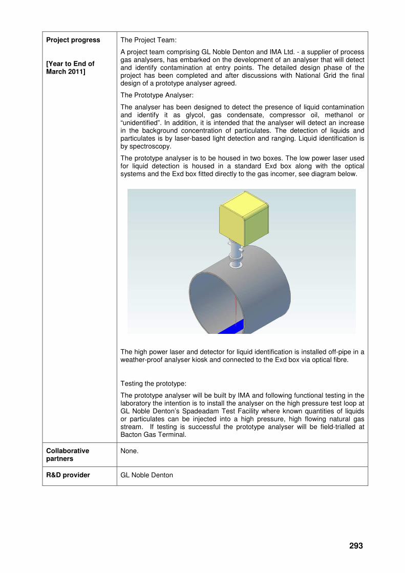
The Prototype Analyser:
The analyser has been designed to detect the presence of liquid contamination and identify it as glycol, gas condensate, compressor oil, methanol or “unidentified”. In addition, it is intended that the analyser will detect an increase in the background concentration of particulates. The detection of liquids and particulates is by laser-based light detection and ranging. Liquid identification is by spectroscopy.
The prototype analyser is to be housed in two boxes. The low power laser used for liquid detection is housed in a standard Exd box along with the optical systems and the Exd box fitted directly to the gas incomer, see diagram below.
The high power laser and detector for liquid identification is installed off-pipe in a weather-proof analyser kiosk and connected to the Exd box via optical fibre.
Testing the prototype:
The prototype analyser will be built by IMA and following functional testing in the laboratory the intention is to install the analyser on the high pressure test loop at GL Noble Denton’s Spadeadam Test Facility where known quantities of liquids or particulates can be injected into a high pressure, high flowing natural gas stream. If testing is successful the prototype analyser will be field-trialled at Bacton Gas Terminal.
Collaborative partners
None.
R&D provider GL Noble Denton
294
Pipelines
Pipeline Route surveys
Project title Combined Geophysics Tool for Pipelines Routeing & Risk Assessment
Project Engineer Matthew Sumerling
Description of project
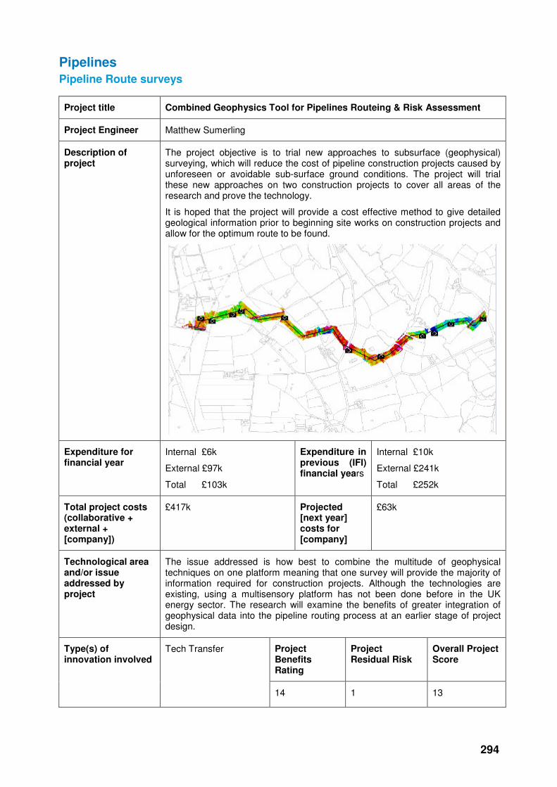
The project objective is to trial new approaches to subsurface (geophysical) surveying, which will reduce the cost of pipeline construction projects caused by unforeseen or avoidable sub-surface ground conditions. The project will trial these new approaches on two construction projects to cover all areas of the research and prove the technology.
It is hoped that the project will provide a cost effective method to give detailed geological information prior to beginning site works on construction projects and allow for the optimum route to be found.
Expenditure for financial year
Internal £6k
External £97k
Total £103k
Expenditure in previous (IFI) financial years
Internal £10k
External £241k
Total £252k
Total project costs (collaborative + external + [company])
£417k Projected [next year] costs for [company]
£63k
Technological area and/or issue addressed by project
The issue addressed is how best to combine the multitude of geophysical techniques on one platform meaning that one survey will provide the majority of information required for construction projects. Although the technologies are existing, using a multisensory platform has not been done before in the UK energy sector. The research will examine the benefits of greater integration of geophysical data into the pipeline routing process at an earlier stage of project design.
Project Benefits Rating
Project Residual Risk
Overall Project Score
Type(s) of innovation involved
Tech Transfer
14 1 13

295
Expected benefits of project
Cost savings of 5:1 are claimed for the use of a mobile multi-sensor platform, compared to traditional subsurface survey methods (saving on costs of liaising with landlords and matching up disparate datasets from individual specialists). It is claimed that a corridor 2.5km x 40m could be surveyed each day with the mobile multisensory platform. By undertaking subsurface surveys of the soil composition before and after a pipeline is laid, National Grid has the data available to deal with (e.g. counter) any compensation claims from the landlord that the soil composition (i.e. soil type and %clay) has been changed.
The development of a best practice manual, decision support tool and survey data visualisation will help to ensure that the above benefits are available for future pipeline construction projects.
Expected timescale of project
4 years Duration of benefit once achieved
Lifetime of inserted pipes
Probability of success
60% Project NPV = (PV benefits – PV costs) x probability of success
£3,669k
Potential for achieving expected benefits
Phase 1: The potential for achieving the expected benefits remains high for the Route Corridor selection despite issues surrounding land access which increased the costs and prevented access to all sections of all routes. The method of integrating the geophysical findings with the environmental study findings needs to be reviewed and refined to gain maximum benefit.
Phase 2: The potential for achieving the expected benefits remains high despite some issues with the equipment being very sensitive and picking up unwanted interference from the surroundings. Cost-benefit analysis will need to be carried out to determine the level of sensitivity required. The benefits will only be able to be assessed following the post-construction survey.
Project progress
[Year to End of March 2011]
Phase 1 of the Hornsea-Beeford Geophysical survey works is complete and the draft Phase 1 report has been delivered. It is still awaiting final review of the route selection criteria adopted by Zetica to ensure the method of integrating the geophysical findings with the environmental study findings is sufficiently refined to gain maximum benefit.
Phase 2 of the works has been initiated. Pre-Construction Surveys have taken place on the Hole House Farm Pipeline construction project. The Post-Construction surveys will take place one the pipeline route has been reinstated.
Progress on the Best Practice Manual has also been made, but completion of this will follow completion of physical works in order that all lessons learned can be included.
Collaborative partners
None
R&D provider Zetica
296
Third party inference
Project title Pipeline Impact Detection System
Project Engineer Aroon Parmar
Description of project
Evaluation of the first use of a Threatscan remote-by-satellite pipeline acoustic monitoring system for the detection of third party interference.
Expenditure for financial year
Internal £10k
External £120k
Total £130k
Expenditure in previous (IFI) financial years
Internal £71k
External £320k
Total £391k
Total project costs (collaborative + external + NG)
£522k Projected 2011/12 costs for NG
£0
Technological area and/or issue addressed by project
The objective of the project is to examine the feasibility of an impact detection system for transmission pipelines. GE has developed a solution which has been tested on an operational pipeline in the USA and Germany. The impact detection system will be installed on No 7 feeder for trial.
Project Benefits Rating
Project Residual Risk
Overall Project Score
Type(s) of innovation involved
Radical
14 2 12
Expected benefits of project
Once the system has been installed on No 7 feeder it is hoped that it will enable National Grid to identify location of Third Party plant and equipment working in close proximity to the pipeline without physical impact damage taking place. This will allow National Grid to take proactive precautionary measures to safeguard the system integrity before damage occurs.
Expected timescale of project
4 years Duration of benefit once achieved
5 years
Probability of success
60% Project NPV = (PV benefits – PV costs) x probability of success
£184k
Potential for achieving expected benefits
The system has now been shown to be effective for detecting actual impacts on the transmission system. There is work required to fine tune the detection algorithm in order to detect encroachment activities although GE seem confident that this can be achieved.
Project progress
[Year to End of March 2011]
The issues surrounding the delays to the project that were reported last year have been resolved. Remediation has been carried out by GE on the installation work deemed of low quality. Upgrades to the batteries, wind turbines and solar panels have now been completed and the system is currently exhibiting a good period of reliability.
297
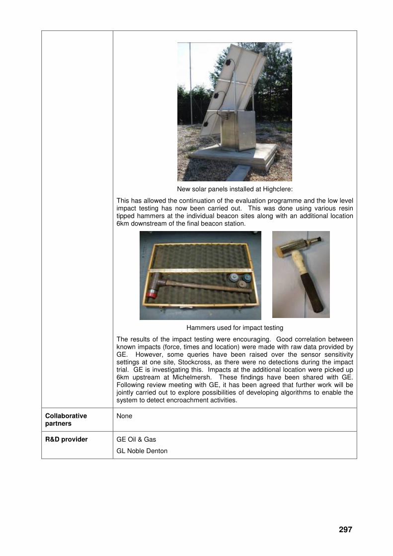
New solar panels installed at Highclere:
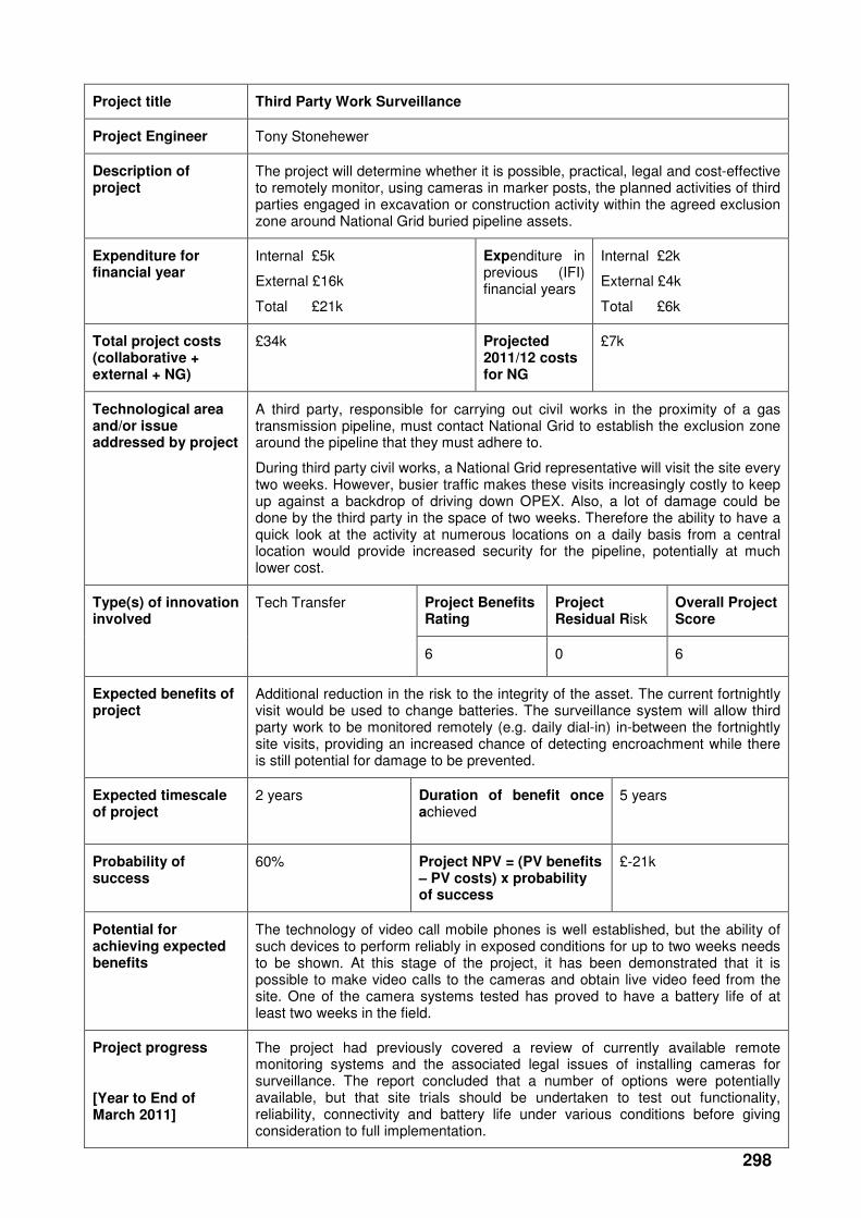
This has allowed the continuation of the evaluation programme and the low level impact testing has now been carried out. This was done using various resin tipped hammers at the individual beacon sites along with an additional location 6km downstream of the final beacon station.
Hammers used for impact testing
The results of the impact testing were encouraging. Good correlation between known impacts (force, times and location) were made with raw data provided by GE. However, some queries have been raised over the sensor sensitivity settings at one site, Stockcross, as there were no detections during the impact trial. GE is investigating this. Impacts at the additional location were picked up 6km upstream at Michelmersh. These findings have been shared with GE. Following review meeting with GE, it has been agreed that further work will be jointly carried out to explore possibilities of developing algorithms to enable the system to detect encroachment activities.
Collaborative partners
None
R&D provider GE Oil & Gas
GL Noble Denton
298
Project title Third Party Work Surveillance
Project Engineer Tony Stonehewer
Description of project
The project will determine whether it is possible, practical, legal and cost-effective to remotely monitor, using cameras in marker posts, the planned activities of third parties engaged in excavation or construction activity within the agreed exclusion zone around National Grid buried pipeline assets.
Expenditure for financial year
Internal £5k
External £16k
Total £21k
Expenditure in previous (IFI) financial years
Internal £2k
External £4k
Total £6k
Total project costs (collaborative + external + NG)
£34k Projected 2011/12 costs for NG
£7k
Technological area and/or issue addressed by project
A third party, responsible for carrying out civil works in the proximity of a gas transmission pipeline, must contact National Grid to establish the exclusion zone around the pipeline that they must adhere to.
During third party civil works, a National Grid representative will visit the site every two weeks. However, busier traffic makes these visits increasingly costly to keep up against a backdrop of driving down OPEX. Also, a lot of damage could be done by the third party in the space of two weeks. Therefore the ability to have a quick look at the activity at numerous locations on a daily basis from a central location would provide increased security for the pipeline, potentially at much lower cost.
Project Benefits Rating
Project Residual Risk
Overall Project Score
Type(s) of innovation involved
Tech Transfer
6 0 6
Expected benefits of project
Additional reduction in the risk to the integrity of the asset. The current fortnightly visit would be used to change batteries. The surveillance system will allow third party work to be monitored remotely (e.g. daily dial-in) in-between the fortnightly site visits, providing an increased chance of detecting encroachment while there is still potential for damage to be prevented.
Expected timescale of project
2 years Duration of benefit once achieved
5 years
Probability of success
60% Project NPV = (PV benefits – PV costs) x probability of success
£-21k
Potential for achieving expected benefits
The technology of video call mobile phones is well established, but the ability of such devices to perform reliably in exposed conditions for up to two weeks needs to be shown. At this stage of the project, it has been demonstrated that it is possible to make video calls to the cameras and obtain live video feed from the site. One of the camera systems tested has proved to have a battery life of at least two weeks in the field.
Project progress
[Year to End of March 2011]
The project had previously covered a review of currently available remote monitoring systems and the associated legal issues of installing cameras for surveillance. The report concluded that a number of options were potentially available, but that site trials should be undertaken to test out functionality, reliability, connectivity and battery life under various conditions before giving consideration to full implementation.
299
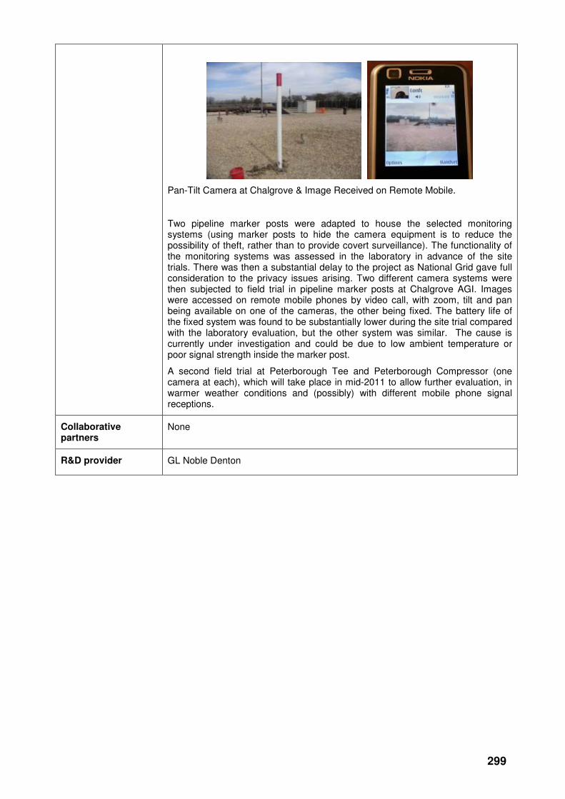
Pan-Tilt Camera at Chalgrove & Image Received on Remote Mobile.
Two pipeline marker posts were adapted to house the selected monitoring systems (using marker posts to hide the camera equipment is to reduce the possibility of theft, rather than to provide covert surveillance). The functionality of the monitoring systems was assessed in the laboratory in advance of the site trials. There was then a substantial delay to the project as National Grid gave full consideration to the privacy issues arising. Two different camera systems were then subjected to field trial in pipeline marker posts at Chalgrove AGI. Images were accessed on remote mobile phones by video call, with zoom, tilt and pan being available on one of the cameras, the other being fixed. The battery life of the fixed system was found to be substantially lower during the site trial compared with the laboratory evaluation, but the other system was similar. The cause is currently under investigation and could be due to low ambient temperature or poor signal strength inside the marker post.
A second field trial at Peterborough Tee and Peterborough Compressor (one camera at each), which will take place in mid-2011 to allow further evaluation, in warmer weather conditions and (possibly) with different mobile phone signal receptions.
Collaborative partners
None
R&D provider GL Noble Denton
300
Project title Automatic Risk-based Handling of Plant Enquiries
Project Engineer Rob Greaves
Description of project
Development and trial of an automated web-based response service to advise developers of construction restrictions in the vicinity of National Grid energy transmission assets.
Expenditure for financial year
Internal £23k
External £68k
Total £92k
Expenditure in previous (IFI) financial years
Internal £6k
External £8k
Total £14k
Total project costs (collaborative + external + [company])
£407K Projected [next year] costs for [company]
£0
Technological area and/or issue addressed by project
This project is evaluating whether the risk of third party interference can be reduced by automatic handling of developers’ enquiries relating to critical National Grid assets. Such interference can have consequences for security of energy supply, public safety and the environment, together with the associated operational costs and costs from potential prosecution and/or damages claims.
Interference damage from third party developers, causing a London black-out, is a credible and potentially costly incident. Having a system that gives instant, repeatable, reliable responses to those third parties (including utilities, contractors and local government) involved in development work in the vicinity of National Grid assets should reduce the risk of interference damage.
Third party interference causing environmental damage is also a credible possibility. Methane released from gas pipelines is 20 times more damaging than carbon dioxide. Oil releases from electrical cables can lead to the risk of prosecution, especially if not discovered by National Grid at the time of the damage.
Project Benefits Rating
Project Residual Risk
Overall Project Score
Type(s) of innovation involved
Tech Transfer
13 -6 19
Expected benefits of project
The proposed system is designed to mitigate the risk of third party damage.
The system will provide comprehensive, accurate and timely asset information and advice based on agreed plant protection rules. Known areas of critical supply and priority/vulnerable customers can be defined in the system and monitored for high risk works. Notification emails can be triggered to plant protection engineers when enquiries are received matching criteria setup in the system, such as the examples listed above or when monitoring named users/organisations that may be causing frequent damage or near misses.
National Grid Transmission Land and Development currently handle plant location enquiries from external organisations on a manual basis, utilising a team of about 7 fulltime employees. With an automated response service in place, this team could focus more time on any exceptions, for example the more difficult enquiries, as well as conducting quality assurance and identifying potential improvements to the automated response service.
Expected timescale of project
3 years Duration of benefit once achieved
5 years
301
Probability of success
60% Project NPV = (PV benefits – PV costs) x probability of success
£86k
Potential for achieving expected benefits
The external trial is nearing completion and there is a high level of confidence in the reliability of the system and the viability of providing an external facing system for use by third parties. The expectation is that the project will realise the intended benefits.
Project progress
[Year to End of March 2010]
A pilot system is available for a trial evaluation following the completion of the following:
• Codification of National Grid Transmission Asset Protection rules for use in the automatic response system
• Development of module to generate asset locations plans for National Grid Transmission apparatus against OS background mapping, with appropriate disclaimers, legends and warnings.
• Development of web-based system to allow submission of plant location enquiries, and return by email of appropriate responses (as defined in the codified Asset Protection rules), with a plan attached as appropriate.
• The development of the trial system and support of the system to prove the feasibility of handling plant enquiries through an external facing self service website. Collection of feedback from trial participants and successful completion of the trial at the end of March 2011.
Collaborative partners
National Grid Gas Distribution, National Grid Electricity Transmission.
R&D provider GL Industrial Services (UK) Ltd
302
Road Crossing Maintenance
Project title Optimisation of Integrity Management at Sleeved Crossings
Project Engineer Rob Stockley / Joanne Harris
Description of project
This project is looking into alternative fills for the 1100 Nitrogen sleeves that were installed on the NTS in the 60’s and 70’s. The valves and rubber hoses connecting the sleeves have begun to perish and difficulties exist in maintaining pressure. This project will look to address that issue.
Expenditure for financial year
Internal £8k
External £60k
Total £68k
Expenditure in previous (IFI) financial years
Internal £3k
External £27k
Total £30k
Total project costs (collaborative + external + NG)
£129k
Projected 2011/12 costs for NG
£30k
Technological area and/or issue addressed by project
The aim of the project is to carry out research in order to determine:
• Alternative solutions to the use of nitrogen for providing an inert atmosphere and seal within the sleeve. This should include a review of research carried out and the evidence available to prove a product’s fitness for purpose and long term performance. It should also consider the level of proven operator experience.
• International best practice on sleeve management, picking up on the techniques currently being employed within the European gas industry.
Project Benefits Rating
Project Residual Risk
Overall Project Score
Type(s) of innovation involved
Incremental
12 0 12
Expected benefits of project
The purpose of this project is to determine and quantify the potential benefits for the UK gas transmission system using alternative methods for providing an inert atmosphere within existing pipe sleeves and to identify the costs of these alternative techniques, ease of installation, ongoing maintenance requirements, performance and overall reliability compared to current practice. This work will include a review of the appropriate fill mechanism for each product.
Expected timescale of project
3 Years Duration of benefit once achieved
5 Years
Probability of success
60% Project NPV = (PV benefits – PV costs) x probability of success
£-25k
Potential for achieving expected benefits
The information gathered on performance, costs, practical experience and integrity management approach of other operators can then be used to formulate a long term investment plan for sleeves on the NTS. At least two alternatives will now be taken forward by National Grid for field evaluation.
Project progress [March 2011]
The initial part of the project had reported details of 8 materials that could be used as an alternative fill for the sleeves to replace nitrogen. These varied from gels to viscous fluids to gases, all selected due to their ability to control corrosion and also be injected into the sleeve through existing connections (or with

303
minimal alterations).
After further consideration, the alternative fill gases were removed from the option due to the issues with maintaining pressure. Four materials (gel or viscous fluid) were taken forward to further trials.
On the basis of this year’s trials, at least two of the four short-listed materials have been found to perform as the manufacturers claim and we will be moving forward to test these products in the field.
Consideration is currently being given to further investigation of a third material from the short list, subject to the findings of the manufacturer’s own investigation into issues highlighted by this project.
The manufacturer of the remaining short-listed material declined the opportunity to complete the study. This means there is a spare test rig available for the above-mentioned further investigation of the third material, should this be required.
Photograph of the final test rig, prior to filling.
Collaborative partners
None
R&D provider GL Noble Denton
304
Excavations
Project title MTM (Magnetic Tomography Method) Pipeline Inspection System: Evaluation & Validation
Project Engineer Pete Martin
Description of project
Conduct field trials to evaluate this new inspection method’s ability to detect significant metal loss features on buried National Grid pipelines and validate the method’s output by subsequent selected excavation and physical examinations of the pipelines.
Expenditure for financial year
Internal £5k
External £70k
Total £75k
Expenditure in previous (IFI) financial years
Internal £0
External £0
Total £0
Total project costs (collaborative + external + NG)
£135k Projected 2011/12 costs for NG
£55k
Technological area and/or issue addressed by project
Uniqueness of the MTM Technique: None of the techniques, currently employed above-ground to assess the condition of buried pipelines, are capable of locating coating disbondment. However, the MTM technique is now claimed to be able to locate coating disbondment from above ground, and therefore provide similar information to that generated during an in-line inspection (ILI).
MTM technology has been developed to be an innovative, non-intrusive and non-contact method of inspection which can provide 100% inspection of a pipeline from above ground. It is said to be capable of locating pipeline material anomalies, characterizing these anomalies and forecasting the need for follow-up actions
How it Works: The MTM inspection technique has recently appeared in the UK market place and is currently being marketed by Transkor Ltd. The technique measures distortions in the earth’s magnetic field due to the presence of buried objects such as a pipeline. Areas of high stress in the pipeline, cause significant distortion of the earth’s magnetic field that surround the pipeline and these areas of distortion can be detected from the surface. Excavation of these areas can then be made to determine the cause of the distortion. The technique is claimed to have the following advantages over other above ground techniques:
• No need for advanced preparation or change to the pipeline’s operating conditions.
• Suitable for any pipeline regardless of type of construction, type of medium transported and presence of flow.
• Does not magnetize the pipe.
• Reveals metal loss features and cracking.
The technique is claimed to be of particular benefit where metal loss features occur under disbonded coating. Although these features are detectable using ILI tools, none of the above ground survey techniques, currently employed on pipelines, are capable of locating or sizing metal loss features.
Historical Note: In 2007/8, the MTM system was trialled in the United States by the NE Gas Alliance of which, National Grid US is a partner. The trial was performed in Manhattan on a number of buried pipelines, but due to problems, the pipes were never excavated to evaluate the MTM results and as a consequence of this the MTM inspection results were not confirmed. Consequently, the MTM system still requires to be evaluated by National Grid to determine the extent of it’s abilities to detect significant features on National Grid pipelines.
305
Project Benefits Rating
Project Residual Risk
Overall Project Score
Type(s) of innovation involved
Radical
12 0 12
Expected benefits of project
If the MTM system can truly detect the magnetic signature created by significant metal loss on a buried pipeline, the biggest benefit will be that it should enable National Grid to tackle a potentially significant problem that is starting to generate concern.
The potentially significant problem is corrosion, caused by disbondment of the coal-tar coating on buried pipelines (most of the pipeline network is now exceeding its original 40-year design life and coal tar coatings, in particular, are giving rise to concern, because coal-tar is a liquid, albeit a very viscous one). Where disbondment occurs, water tends to seep between the pipeline and its coating by capillary action, where it forms a “closed” corrosion cell. The significance of it being a “closed” corrosion cell is that cathodic protection (CP) does nothing to reduce the rate of corrosion (CP only works to reduce corrosion of exposed defects).
The standard approach to identifying and controlling corrosion on buried pipelines is to conduct in-line inspection (ILI) surveys every 14 years. Where sub-critical defects are detected by ILI, the level of CP is increased in conjunction with ‘close intervals potential surveys’ (CIPS), which are undertaken much more frequently.
A typical pipeline may have up to 3000 sub-critical defects. 70% of pipelines are coated with coal-tar. International experience suggests that as much as 20% of corrosion defects may be caused by disbondment. However, National Grid has no current method to confirm this. Safety considerations dictate that National Grid cannot afford to wait 14 years to measure corrosion rate of defects over the period between two ILI surveys. CIPS can detect the location of lowest potentials but cannot diagnose the nature of the corrosion and CP will do nothing to halt or delay the corrosion in a “closed” corrosion cell.
If MTM works, it could be used to conduct surveys from the surface during the 14 year interval between ILI surveys. It may be able to characterise coating disbondment on a single survey. Alternatively, if successive MTM surveys showed continuing metal loss despite CP levels being raised, this could indicate a corrosion mechanism that is not affected by CP (e.g. a “closed” corrosion cell caused by coating disbondment). The metal loss could then be monitored by MTM until the defect became critical, at which point National Grid would dig down and repair the pipeline.
Without MTM surveys (or a comparable solution), National Grid has no way of knowing how extensive is the problem of “closed” corrosion cells caused by coating disbondment. If coating disbondment is a significant problem, National Grid then has no way of monitoring it during the 14 years between ILI surveys. In order to manage the risk to the public of pipeline failure from this type of corrosion, National Grid would be required to either increase the frequency of ILI surveys or dig down and visually inspect the worst of the 3000 or so sub-critical defects on the typical pipeline. The increased “pig and/or dig” activity would lead to an escalation in maintenance costs that National Grid would be keen to avoid:
• Typical ILI survey cost for a pipeline (including disruption to network capacity): £80k – £100k.
• Typical excavation cost: £20k – £30k (occasionally rising to £250k in mountainous areas).
• Indicative cost of MTM service (equipment hire, plus qualified operator and provision of analysis): £30k /month.
National Grid is currently part way through an aggressive CIPS survey programme covering a significant percentage of the network. For example, this has highlighted 22 defects that warrant further investigation on Feeder No.12 in Scotland between Aberdeen and Glenmavis. If MTM works, it could be used to prioritise any subsequent dig activity. Another example would be No.2 Feeder
306
between Dowlais and Dyffryn in Wales. This is a coal tar coated pipeline in a mountainous region, where dig activity would be at a premium.
If the project is successful, NGG Transmission might reasonably expect in the course of 10 years to delay by an average of 5 years the cost of digging down to further investigate 1% of the current total 38,000 sub-critical defects. The cost of hiring the MTM kit for 4 months each year would be around £120k per year.
Expected timescale of project
2 years Duration of benefit once achieved
5 years
Probability of success
60% Project NPV = (PV benefits – PV costs) x probability of success
£43k
Potential for achieving expected benefits
Since the MTM project started in September 2010, a site trial has been conducted to evaluate the MTM system on sections of 3 National Grid high pressure pipelines. The MTM results have been directly compared to ILI results and this analysis has shown that there is a good correlation between the two sets of data. A recent dig on the Partington to Warburton pipeline confirmed an area of corrosion that was detected by both systems.
The work carried out to date to evaluate the MTM system has shown that this equipment has the potential to be of significant use to National Grid for the detection of features in buried high pressure gas pipelines.
Project progress
[Year to End of March 2011]
Between September & December 2010, GLND worked with personnel from Transkor UK reviewing and developing their existing field and safety procedures for the MTM system with the aim of having these procedures approved by National Grid to be able to perform field trials.
In parallel with this, using the UPTIME system GLND personnel identified 6 sections of pipe on 3 pipelines that contained varying levels of defects that were considered suitable for the MTM system to inspect.
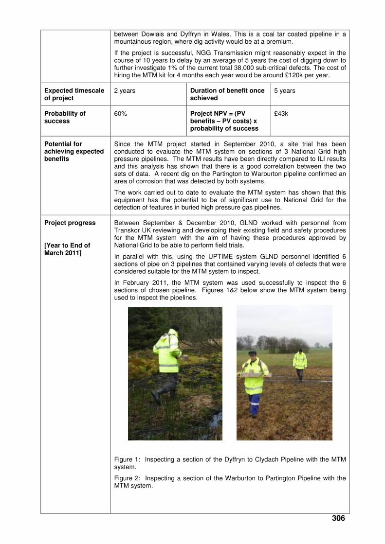
In February 2011, the MTM system was used successfully to inspect the 6 sections of chosen pipeline. Figures 1&2 below show the MTM system being used to inspect the pipelines.
Figure 1: Inspecting a section of the Dyffryn to Clydach Pipeline with the MTM system.
Figure 2: Inspecting a section of the Warburton to Partington Pipeline with the MTM system.

307
Following completion of the onsite trails, Transkor have produced an inspection report. This was completed in March 2011 and the results have been compared to the ILI UPTIME results. This has shown that there is a very good correlation between the two sets of data.
National Grid Distrbutiion arranged for a P11 dig to be performed on a section of pipe located at Partington. The ILI result had indicated an area of metal loss between 20% and 25%. The MTM system had also detected a feature at the same location. The subsequent investigation of this area on the pipeline, located an area of corrosion consisting of heavy pits, located at the 5 o’clock position and having a length of 0.92 metre, see Figure 3 below:
Figure 3: Area of corrosion pitting found on Partington pipe.
The pit depths were measured and the deepest was found to have grown 30% into the pipe wall. The onsite investigation, confirmed that both the ILI and MTM results were correct. In particular, the MTM system was capable of remotely locating the corrosion feature from the surface and giving an accurate GPS location.
The MTM system uses a traffic light system to rank the located features (Red, Amber & Green) with red being high risk green low risk. The feature at Partington had been ranked as green and the outcome of the P11 assessment ranked the corrosion pitting as superficial. This result also shows a good correlation between the ILI and MTM results for this particular corrosion feature.
Work is now underway to compile a GL report detailing the work carried out to date and discussing the results from the MTM site trials. The MTM project is currently on track to both time and budget.
Collaborative partners
None
R&D provider GL Noble Denton
308
Project title Development of AC Over Line Survey System
Project Engineer Peter Martin
Description of project
This project will deliver a suitable over line AC survey system that will be used for the initial identification of areas where the levels of AC interference on gas pipelines may require mitigating action. When implemented, the survey system will enable the improved detection and assessment of AC-induced corrosion in gas pipelines, thereby reducing the likelihood of leakage or failure though this particular corrosion process.
Expenditure for financial year
Internal £5k
External £72k
Total £77k
Expenditure in previous (IFI) financial years
Internal £2k
External £46k
Total £48k
Total project costs (collaborative + external + NG)
£185k Projected 2011/12 costs for NG
£60k
Technological area and/or issue addressed by project
AC corrosion has been documented in the UK, mainland Europe and North America. Through-wall failures have been recorded and corrosion rates as high as 1.4 mm/yr calculated. A 2004 report indicates that 24 known cases of AC corrosion were reported in Europe (but this is likely to be only a small percentage of the total). These pipelines were not shown to have any defects during conventional DC CIPS surveys. Increasing installation of power lines, rail transit systems and improvements to pipeline coating quality will all continue to increase AC corrosion instances.
Project Benefits Rating
Project Residual Risk
Overall Project Score
Type(s) of innovation involved
Significant
12 6 6
Expected benefits of project
The business benefit is attained through developing a clear view of the levels of AC interference along a pipeline, rather than just at the test points (as is presently the case). Through this process, mitigation measures can be applied, if necessary, enabling the issue to be effectively monitored and controlled. The potential order of magnitude of costs ‘avoided’ are outlined above.
Expected timescale of project
3 years Duration of benefit once achieved
5 years
Probability of success
60% Project NPV = (PV benefits – PV costs) x probability of success
£44k
Potential for achieving expected benefits
Based upon the data captured and analysed from the preliminary field trial there is a high potential for this project achieving the expected benefits.
Whilst further trial data is required to fully corroborate the findings to date, and to qualify the technology options, early indications from the data suggest that the technology can identify areas of high current density.

309
Project progress
[Year to End of March 2011]
The project experienced a significant delay in the availability of the candidate field device and the custom design, development and build of the prototype AC module.
Further theoretical physics work was conducted in relation to electromagnetic (EM) inductance on the field device and the impact that this could have on any measurements taken in the field. As a result of this a number of mitigating technology options were explored. This resulted in the design, development and bench testing of 2 trailing cable technologies designed to shield the trailing cable from EM induction.
Bench testing of the trailing cable technologies was undertaken to determine the effectiveness of the shielding technology. The testing took place under controlled conditions using a simulated real world electromagnetic field.
A draft operational procedure was also written for the candidate device and the supporting trailing cable technologies.
Following promising results under laboratory conditions for the candidate device, the prototype AC Module and the 2 trailing cable technologies it was decided to test the technology in the field.
Bad weather conditions in December and January added some further delays to the project. However, in early March the first field trial was conducted on the pipeline adjoining Stallingborough Power Station. This pipeline has experienced AC corrosion in the past and it is known to have very high levels of AC current and voltage induced on the pipeline as regularly monitored via test posts / coupons.
The field trial was designed to test 3 cable technologies with the candidate device and the associated prototype AC module. The cables technologies tested were as follows:
• Standard MC Miller copper wire as used in a standard CIPS survey for control purposes i.e no shielding from AC inductance
• Specially designed 0.3mm Coaxial cable – Shielded against EM induction
• 2 x MC Miller copper wires in very close proximity combined with a prototype shielding device designed to cancel out any EM inductance / interference.
In addition the following were also tested during the first field trial:
• Usability of the candidate device, and each cable technology
• Deployment of cable technology
• Test the draft operational procedures for the device and the trailing cable technologies in the real world.
• Soil resistivity tests
• Static voltage and current readings
• Test post voltage and current monitoring
• Measurement of the EM field generated by the overhead power lines.
A good data set was collected for each of the 3 scenarios and a series of lessons learnt were captured.
The initial data has been processed in accordance with the formula identified in the theoretical physics studies and this initial data has now been analysed.
310
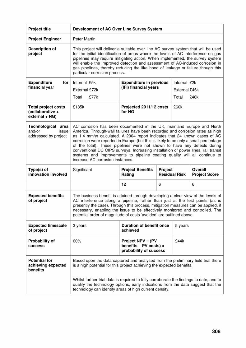
Connecting AC Voltage and Current Readings at the test post at Stallingborough power station
MC Miller Candidate device with prototype AC CIPS module and measurement probes attached during field trail at Stallingborough power station
The MC Miller candidate Device with Prototype AC CIPS Module attached
311
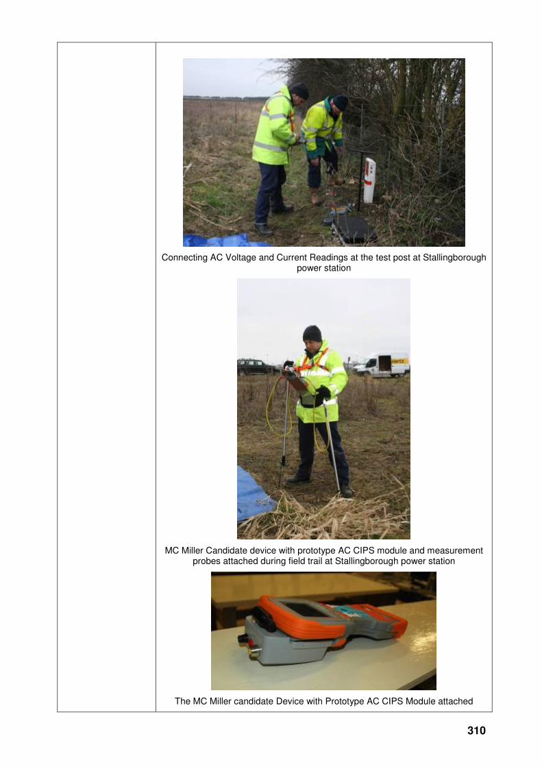
Bench testing of cable real shielding
Sample output of data analysis from the Stallingborough field trial
Collaborative partners
None
R&D provider GL Noble Denton
312
Re-use of Gas Assets
Project title Research into Requirements for Gaseous Phase CO2 Transmission
Project Engineer Russell Cooper
Description of project
National Grid is considering the change of use of existing natural gas National Transmission System (NTS) transmission pipelines so that they can be capable of transporting anthropogenic Carbon Dioxide (CO2) from large emitters, such as power stations, to a location where the CO2 can be safely stored. This will require full demonstration, through preparation of a safety case that the activity can be carried out safely.
The project involves a range of research and development activities to be undertaken in order that a robust safety justification for the design and operation of gaseous phase CO2 pipelines can be prepared.
Expenditure for financial year
Internal £21k
External £1095k
Total £1121k
Expenditure in previous (IFI) financial years
Internal £37k
External £639k
Total £676k
Total project costs (collaborative + external + [company])
£2502k Projected [next year] costs for [company]
£710k
Technological area and/or issue addressed by project
CO2 poses safety risks to people and the complex phase characteristics of the fluid require specialist modelling to assess the hydraulic behaviour on pipeline design and operation.
The nature of pure CO2 changes from gaseous condition to a dense phase condition at the critical point. In the gaseous phase, CO2 behaves as a heavy gas, but in the dense phase, the “fluid” has the viscosity of a gas and the density of a liquid. While transportation of dense phase CO2 offers efficiencies due to the properties of the fluid, National Grid’s immediate interests are in the transportation of gaseous phase CO2.
The heavy gas behaviour of the gaseous phase CO2 affects the dispersion of the gas and therefore the distances over which it disperses poses a hazard to people. Anthropogenic CO2 contains impurities, and the effects of these impurities on the phase boundary, hydraulic behaviour, hazard distance and pipe integrity require assessment need to be investigated and understood in order that pipeline design and pipeline operation can be carried out safely.
Project Benefits Rating
Project Residual Risk
Overall Project Score
Type(s) of innovation involved
Radical
19 5 14
Expected benefits of project
This research provides a benefit to gas consumers as it enables CO2 networks to be developed through the reuse of existing natural gas pipeline assets. This change of use will enable natural gas consumers to be protected against the decommissioning costs and associated liabilities that would otherwise be required if a natural gas pipeline is no longer required for natural gas transmission. Further value can be captured for gas consumers by reusing existing pipelines for other applications. The value in question may well be underpinned by calculations of residual asset value.
313
Wider energy consumers, including electricity consumers, stand to benefit if the research enables the development of CO2 networks to support carbon capture from coal fired generators. It is possible that without this technology there will be a much diminished role for coal in the UK energy mix, leading potentially to higher electricity prices and an impaired outlook for electricity security of supply.
Consumers will also benefit from the clear environmental benefits that will be delivered to the UK through the effective mitigation of CO2 emissions. The UK Government and European Union both believe that Carbon Capture and Storage (CCS) presents an important opportunity for reducing CO2 emissions. This research can be seen to be aligned with the environmental policies of both national and supra-national bodies, potentially presenting real opportunities to efficiently re-deploy existing natural gas assets in the service of mitigating climate change.
Expected timescale of project
4 years Duration of benefit once achieved
Resale / reuse of assets lifetime of NTS
Probability of success
80% Project NPV = (PV benefits – PV costs) x probability of success
£2,747k
Potential for achieving expected benefits
Good - CO2 transportation through pipelines has been in operation in the United States since the 1970’s. These activities have been mainly focussed on the transport of naturally occurring CO2 from the source to various oil fields for the purposes of delivering Enhanced Oil Recovery (EOR). It is noted though that the CO2 pipelines in the United States are laid in remote areas and very little research work has been carried out relating safety aspects of pipeline operation. However, the knowledge that these pipelines exist and have been in operation for a substantial period of time provides a high degree of confidence that a successful CO2 transportation network can be developed in Europe.
Similar research and development work was carried out for natural gas in the 1970s and 1980s and forms the basis of the safety justification for National Grid’s high pressure transmission network. The results of the work are not directly relevant to the transportation of CO2, but the logic applied and learning obtained will be applied as appropriate which assists in minimising timescales by the application of “lessons learnt”.
National Grid is utilising a range of service providers who have a wealth of experience with this type of R&D work and knowledge of CO2 systems.
To date good progress has been made on the R&D work and National Grid continues to monitor and review the R&D programme.
Project progress
[Year to End of March 2011]
The Research and Development (R&D) work conducted for gaseous phase Carbon Dioxide (CO2) covers the following four main work streams:
Thermodynamic characteristics of gaseous phase CO2.
Fracture control.
Quantified risk assessment.
Pipeline design and integrity.
The following sections outline several of the major work elements undertaken over the last financial year regarding the reuse of existing National Transmission System (NTS) pipeline assets for the transportation of anthropogenic, gaseous phase CO2.
A2 Analysis of two phase flow and hydrate formation in above ground sections
314
The existing pipeline system contains a number of above ground sections in which it is possible that the fluid temperature could drop below the ambient air temperature. In these sections there is a risk that the temperature drop could result in two phase flow and/or hydrate formation. Newcastle University conducted the following two studies:
Study 1 - Liquid formation in above ground pipeline sections
If the temperature were to drop in the above ground pipeline sections then it is possible that the CO2 could enter the two phase region resulting in liquid and gaseous phases being present in the CO2. Under these conditions, it is important to understand the quantity and residence time of the liquid phase in the pipeline. This study included conducting hydraulic modelling of a typical above ground section of pipeline under both static and transient conditions to analyse the phase conditions in the pipeline.
Study 2 - Analysis of the risk of hydrate formation in above ground pipeline sections
It has been postulated that due to the decrease in temperature at above ground pipeline sections that there is a risk that CO2 hydrates could form in the presence of water, causing potential flow assurance issues. This study investigated the risk of hydrate formation in above ground pipeline sections under normal and potential upset water concentrations through a review of the available literature as well as with phase and hydraulic modelling.
The main conclusions from the work are:
The ground temperature, and therefore the temperature of the fluid, controls the phase behaviour and pressure and temperature drop across the above ground sections, particularly in no-flow conditions.
It is only at a ground temperature of 0oC that liquid phase is predicted to form in
the above ground sections. At a minimum operating temperature of 4oC, the
pressure and temperature change due to the elevation differences in the above ground section does not result in a phase change of the CO2 under flowing CO2 conditions.
Hydrate formation will not occur in the above ground sections at the level of water being considered (i.e. ≤50 ppmv). Under upset conditions, it would be predicted that hydrate would be formed in both the pipeline and the above ground sections. Indeed under upset conditions, hydrate will form at temperatures below 8.38
oC.
This work has conservatively estimated that the minimum water content to prevent hydrate formation in the pure CO2-H2O system is 100 ppm(mol).
A3 Odorisation of CO2
Detection of CO2 is an important issue as there is no significant direct human response to CO2 (e.g. smell) that could be useful as a detection mechanism. Elevated concentrations of CO2 are toxic to humans and can result in asphyxiation through displacement of oxygen. Germanischer Lloyd Noble Denton (GLND) examined for National Grid the potential for odorising CO2 so that leaks may be readily detected by the human nose, in a manner comparable to detection of natural gas leaks from distribution networks
GLND found no evidence that the practice of odorising pipeline transported CO2 is currently carried out anywhere in the world. Therefore this would be considered a novel application. However, no reasons were identified as to why pipeline transported CO2 cannot be odorised as a means of leak detection.
GLND recommended that an odorant with repulsive or unpleasant odorant characteristics be used and options for potential odorants were identified. GLND identified two possible odorant options that could be investigated further.
This work wasn’t taken any further as it was determined based on other work conducted that there was no safety justification for the use of odorant to reduce the risks associated with the transportation of gaseous phase CO2.
A4 Corrosion
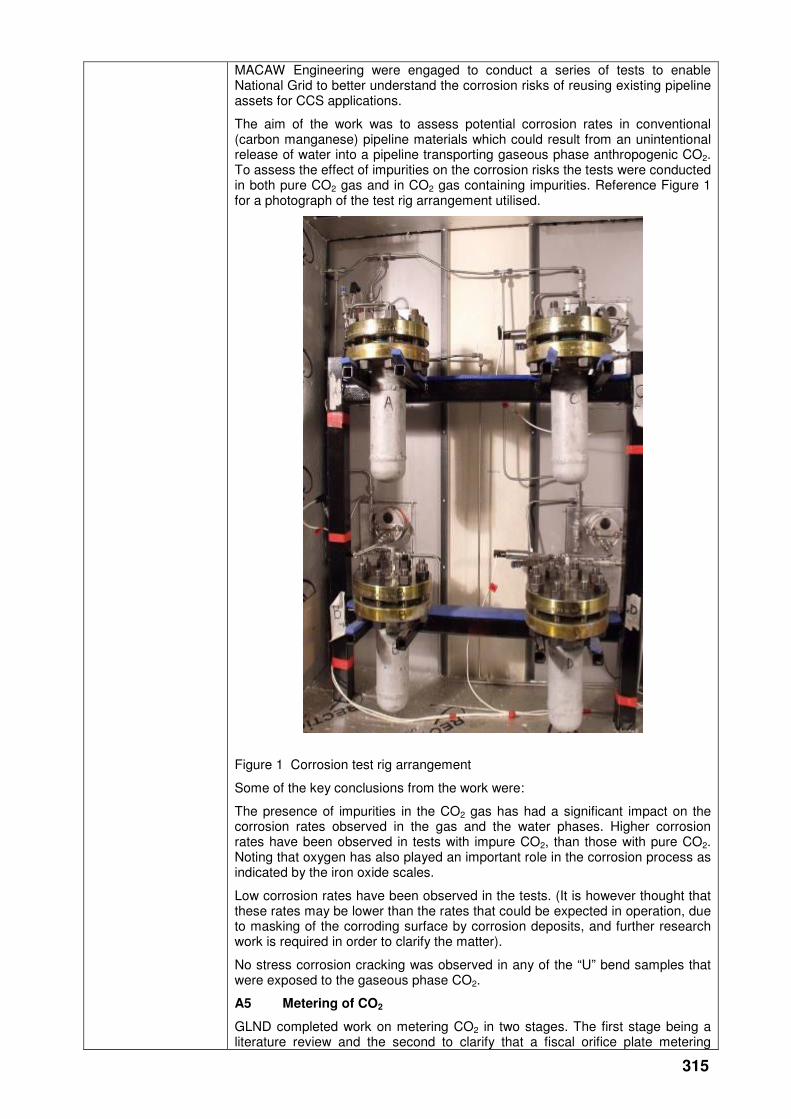
315
MACAW Engineering were engaged to conduct a series of tests to enable National Grid to better understand the corrosion risks of reusing existing pipeline assets for CCS applications.
The aim of the work was to assess potential corrosion rates in conventional (carbon manganese) pipeline materials which could result from an unintentional release of water into a pipeline transporting gaseous phase anthropogenic CO2. To assess the effect of impurities on the corrosion risks the tests were conducted in both pure CO2 gas and in CO2 gas containing impurities. Reference Figure 1 for a photograph of the test rig arrangement utilised.
Figure 1 Corrosion test rig arrangement
Some of the key conclusions from the work were:
The presence of impurities in the CO2 gas has had a significant impact on the corrosion rates observed in the gas and the water phases. Higher corrosion rates have been observed in tests with impure CO2, than those with pure CO2. Noting that oxygen has also played an important role in the corrosion process as indicated by the iron oxide scales.
Low corrosion rates have been observed in the tests. (It is however thought that these rates may be lower than the rates that could be expected in operation, due to masking of the corroding surface by corrosion deposits, and further research work is required in order to clarify the matter).
No stress corrosion cracking was observed in any of the “U” bend samples that were exposed to the gaseous phase CO2.
A5 Metering of CO2
GLND completed work on metering CO2 in two stages. The first stage being a literature review and the second to clarify that a fiscal orifice plate metering
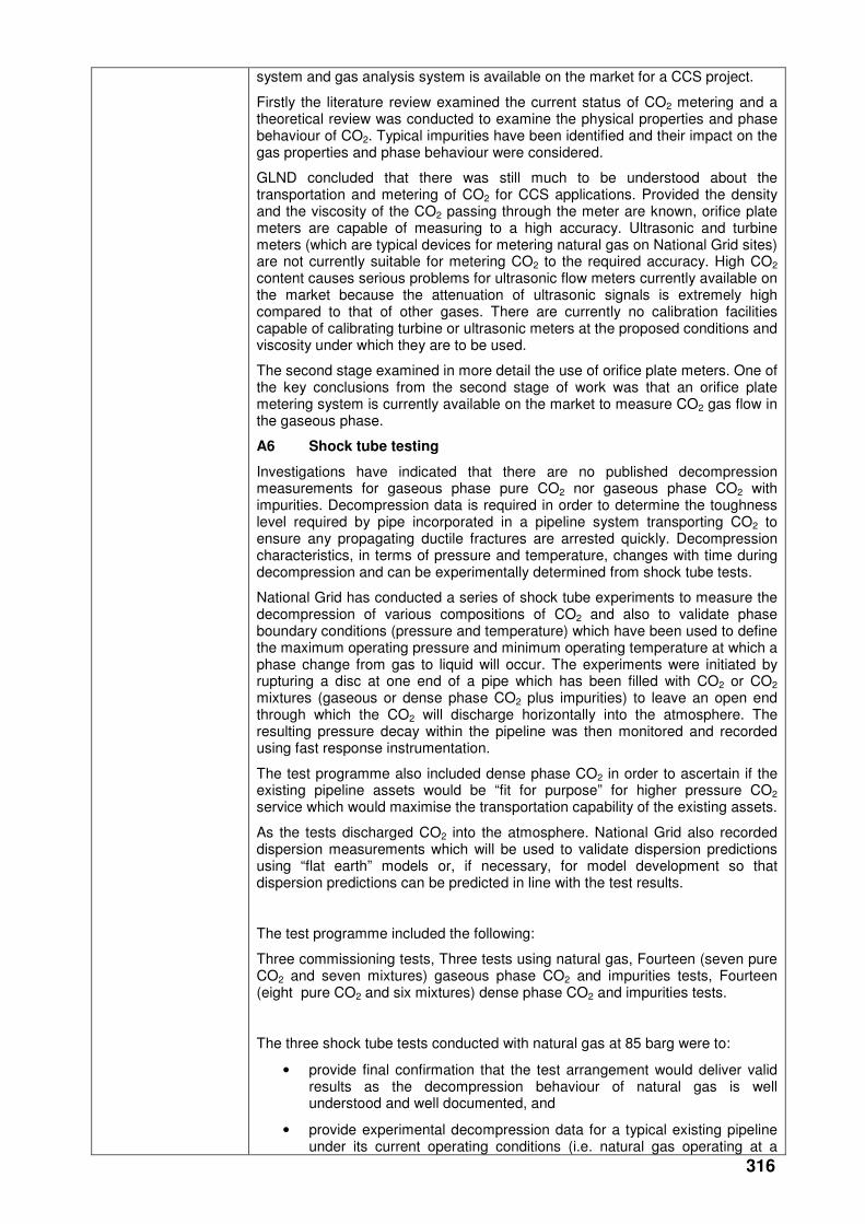
316
system and gas analysis system is available on the market for a CCS project.
Firstly the literature review examined the current status of CO2 metering and a theoretical review was conducted to examine the physical properties and phase behaviour of CO2. Typical impurities have been identified and their impact on the gas properties and phase behaviour were considered.
GLND concluded that there was still much to be understood about the transportation and metering of CO2 for CCS applications. Provided the density and the viscosity of the CO2 passing through the meter are known, orifice plate meters are capable of measuring to a high accuracy. Ultrasonic and turbine meters (which are typical devices for metering natural gas on National Grid sites) are not currently suitable for metering CO2 to the required accuracy. High CO2 content causes serious problems for ultrasonic flow meters currently available on the market because the attenuation of ultrasonic signals is extremely high compared to that of other gases. There are currently no calibration facilities capable of calibrating turbine or ultrasonic meters at the proposed conditions and viscosity under which they are to be used.
The second stage examined in more detail the use of orifice plate meters. One of the key conclusions from the second stage of work was that an orifice plate metering system is currently available on the market to measure CO2 gas flow in the gaseous phase.
A6 Shock tube testing
Investigations have indicated that there are no published decompression measurements for gaseous phase pure CO2 nor gaseous phase CO2 with impurities. Decompression data is required in order to determine the toughness level required by pipe incorporated in a pipeline system transporting CO2 to ensure any propagating ductile fractures are arrested quickly. Decompression characteristics, in terms of pressure and temperature, changes with time during decompression and can be experimentally determined from shock tube tests.
National Grid has conducted a series of shock tube experiments to measure the decompression of various compositions of CO2 and also to validate phase boundary conditions (pressure and temperature) which have been used to define the maximum operating pressure and minimum operating temperature at which a phase change from gas to liquid will occur. The experiments were initiated by rupturing a disc at one end of a pipe which has been filled with CO2 or CO2 mixtures (gaseous or dense phase CO2 plus impurities) to leave an open end through which the CO2 will discharge horizontally into the atmosphere. The resulting pressure decay within the pipeline was then monitored and recorded using fast response instrumentation.
The test programme also included dense phase CO2 in order to ascertain if the existing pipeline assets would be “fit for purpose” for higher pressure CO2 service which would maximise the transportation capability of the existing assets.
As the tests discharged CO2 into the atmosphere. National Grid also recorded dispersion measurements which will be used to validate dispersion predictions using “flat earth” models or, if necessary, for model development so that dispersion predictions can be predicted in line with the test results.
The test programme included the following:
Three commissioning tests, Three tests using natural gas, Fourteen (seven pure CO2 and seven mixtures) gaseous phase CO2 and impurities tests, Fourteen (eight pure CO2 and six mixtures) dense phase CO2 and impurities tests.
The three shock tube tests conducted with natural gas at 85 barg were to:
• provide final confirmation that the test arrangement would deliver valid results as the decompression behaviour of natural gas is well understood and well documented, and
• provide experimental decompression data for a typical existing pipeline under its current operating conditions (i.e. natural gas operating at a
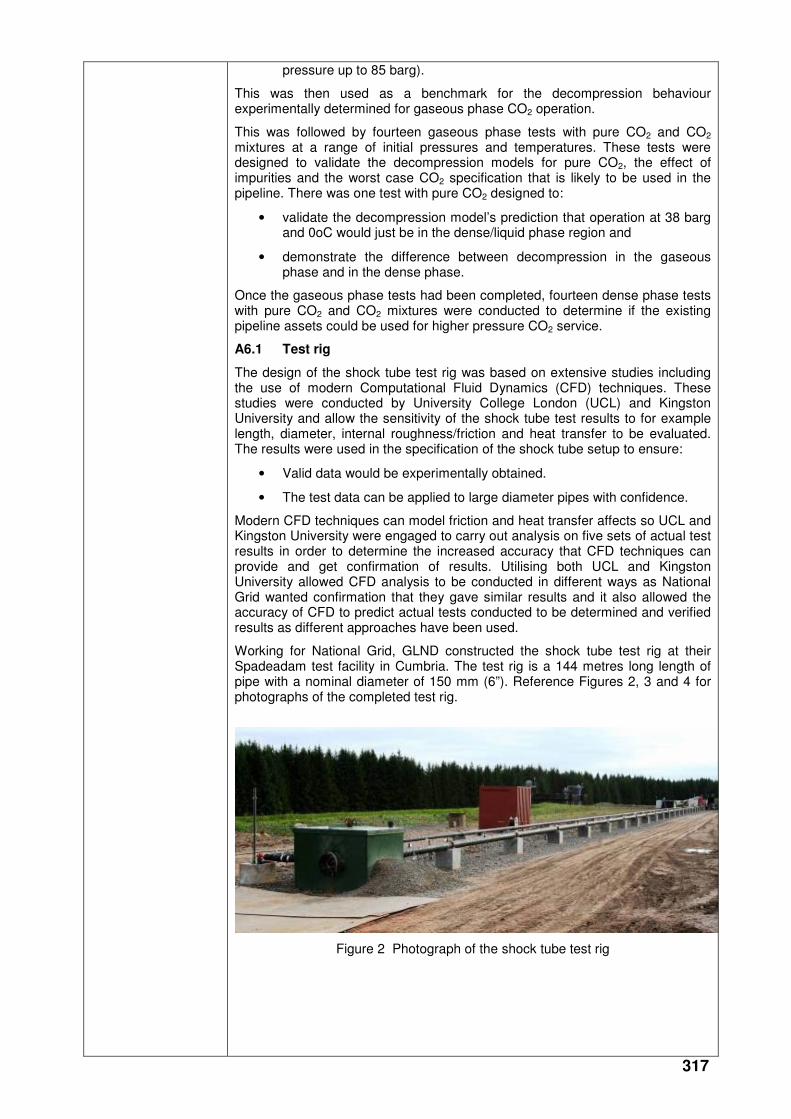
317
pressure up to 85 barg).
This was then used as a benchmark for the decompression behaviour experimentally determined for gaseous phase CO2 operation.
This was followed by fourteen gaseous phase tests with pure CO2 and CO2 mixtures at a range of initial pressures and temperatures. These tests were designed to validate the decompression models for pure CO2, the effect of impurities and the worst case CO2 specification that is likely to be used in the pipeline. There was one test with pure CO2 designed to:
• validate the decompression model’s prediction that operation at 38 barg and 0oC would just be in the dense/liquid phase region and
• demonstrate the difference between decompression in the gaseous phase and in the dense phase.
Once the gaseous phase tests had been completed, fourteen dense phase tests with pure CO2 and CO2 mixtures were conducted to determine if the existing pipeline assets could be used for higher pressure CO2 service.
A6.1 Test rig
The design of the shock tube test rig was based on extensive studies including the use of modern Computational Fluid Dynamics (CFD) techniques. These studies were conducted by University College London (UCL) and Kingston University and allow the sensitivity of the shock tube test results to for example length, diameter, internal roughness/friction and heat transfer to be evaluated. The results were used in the specification of the shock tube setup to ensure:
• Valid data would be experimentally obtained.
• The test data can be applied to large diameter pipes with confidence.
Modern CFD techniques can model friction and heat transfer affects so UCL and Kingston University were engaged to carry out analysis on five sets of actual test results in order to determine the increased accuracy that CFD techniques can provide and get confirmation of results. Utilising both UCL and Kingston University allowed CFD analysis to be conducted in different ways as National Grid wanted confirmation that they gave similar results and it also allowed the accuracy of CFD to predict actual tests conducted to be determined and verified results as different approaches have been used.
Working for National Grid, GLND constructed the shock tube test rig at their Spadeadam test facility in Cumbria. The test rig is a 144 metres long length of pipe with a nominal diameter of 150 mm (6”). Reference Figures 2, 3 and 4 for photographs of the completed test rig.
Figure 2 Photograph of the shock tube test rig
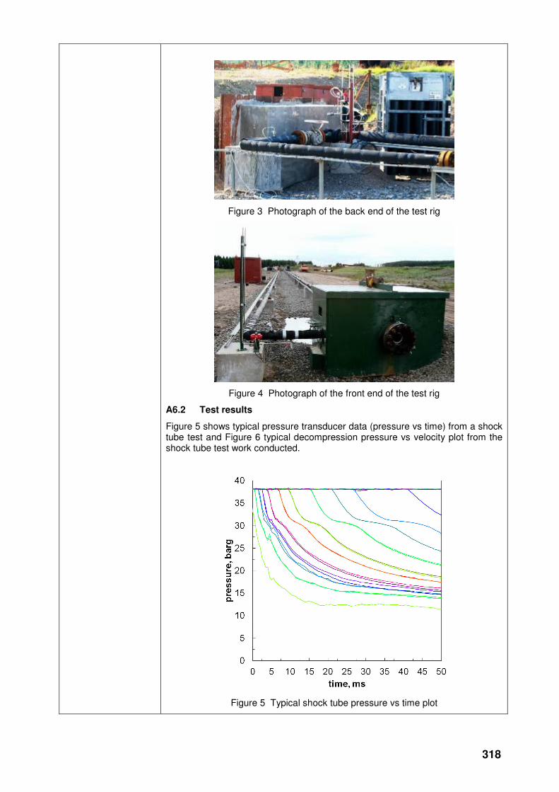
318
Figure 3 Photograph of the back end of the test rig
Figure 4 Photograph of the front end of the test rig
A6.2 Test results
Figure 5 shows typical pressure transducer data (pressure vs time) from a shock tube test and Figure 6 typical decompression pressure vs velocity plot from the shock tube test work conducted.
Figure 5 Typical shock tube pressure vs time plot
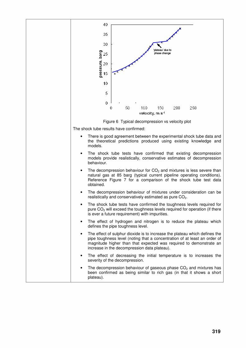
319
Figure 6 Typical decompression vs velocity plot
The shock tube results have confirmed:
• There is good agreement between the experimental shock tube data and the theoretical predictions produced using existing knowledge and models.
• The shock tube tests have confirmed that existing decompression models provide realistically, conservative estimates of decompression behaviour.
• The decompression behaviour for CO2 and mixtures is less severe than natural gas at 85 barg (typical current pipeline operating conditions). Reference Figure 7 for a comparison of the shock tube test data obtained.
• The decompression behaviour of mixtures under consideration can be realistically and conservatively estimated as pure CO2.
• The shock tube tests have confirmed the toughness levels required for pure CO2 will exceed the toughness levels required for operation (if there is ever a future requirement) with impurities.
• The effect of hydrogen and nitrogen is to reduce the plateau which defines the pipe toughness level.
• The effect of sulphur dioxide is to increase the plateau which defines the pipe toughness level (noting that a concentration of at least an order of magnitude higher than that expected was required to demonstrate an increase in the decompression data plateau).
• The effect of decreasing the initial temperature is to increases the severity of the decompression.
• The decompression behaviour of gaseous phase CO2 and mixtures has been confirmed as being similar to rich gas (in that it shows a short plateau).
‘plateau’ due to phase change‘plateau’ due to phase change
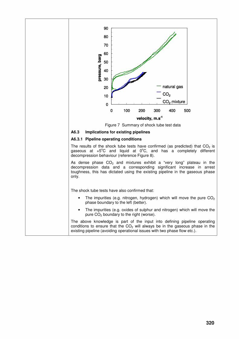
320
Figure 7 Summary of shock tube test data
A6.3 Implications for existing pipelines
A6.3.1 Pipeline operating conditions
The results of the shock tube tests have confirmed (as predicted) that CO2 is gaseous at +5
oC and liquid at 0
oC, and has a completely different
decompression behaviour (reference Figure 8).
As dense phase CO2 and mixtures exhibit a “very long” plateau in the decompression data and a corresponding significant increase in arrest toughness, this has dictated using the existing pipeline in the gaseous phase only.
The shock tube tests have also confirmed that:
• The impurities (e.g. nitrogen, hydrogen) which will move the pure CO2 phase boundary to the left (better).
• The impurities (e.g. oxides of sulphur and nitrogen) which will move the pure CO2 boundary to the right (worse).
The above knowledge is part of the input into defining pipeline operating conditions to ensure that the CO2 will always be in the gaseous phase in the existing pipeline (avoiding operational issues with two phase flow etc.).
0
10
20
30
40
50
60
70
80
90
0 100 200 300 400 500
velocity, m.s-1
pre
ssu
re,
barg
natural gas
CO2
CO2 mixture0
10
20
30
40
50
60
70
80
90
0 100 200 300 400 500
velocity, m.s-1
pre
ssu
re,
barg
natural gas
CO2
CO2 mixture
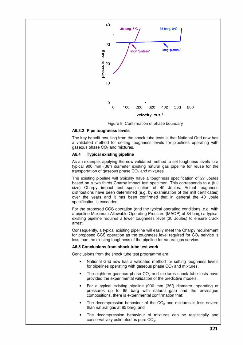
321
Figure 8 Confirmation of phase boundary
A6.3.2 Pipe toughness levels
The key benefit resulting from the shock tube tests is that National Grid now has a validated method for setting toughness levels for pipelines operating with gaseous phase CO2 and mixtures.
A6.4 Typical existing pipeline
As an example, applying the now validated method to set toughness levels to a typical 900 mm (36”) diameter existing natural gas pipeline for reuse for the transportation of gaseous phase CO2 and mixtures.
The existing pipeline will typically have a toughness specification of 27 Joules based on a two thirds Charpy impact test specimen. This corresponds to a (full size) Charpy impact test specification of 40 Joules. Actual toughness distributions have been determined (e.g. by examination of the mill certificates) over the years and it has been confirmed that in general the 40 Joule specification is exceeded.
For the proposed CCS operation (and the typical operating conditions, e.g. with a pipeline Maximum Allowable Operating Pressure (MAOP) of 34 barg) a typical existing pipeline requires a lower toughness level (30 Joules) to ensure crack arrest.
Consequently, a typical existing pipeline will easily meet the Charpy requirement for proposed CCS operation as the toughness level required for CO2 service is less than the existing toughness of the pipeline for natural gas service.
A6.5 Conclusions from shock tube test work
Conclusions from the shock tube test programme are:
• National Grid now has a validated method for setting toughness levels for pipelines operating with gaseous phase CO2 and mixtures.
• The eighteen gaseous phase CO2 and mixtures shock tube tests have provided the experimental validation of the predictive models.
• For a typical existing pipeline (900 mm (36”) diameter, operating at pressures up to 85 barg with natural gas) and the envisaged compositions, there is experimental confirmation that:
• The decompression behaviour of the CO2 and mixtures is less severe than natural gas at 85 barg, and
• The decompression behaviour of mixtures can be realistically and conservatively estimated as pure CO2.
38 barg, 5°C 38 barg, 0°C
short ‘plateau’ long ‘plateau’
38 barg, 5°C 38 barg, 0°C
short ‘plateau’ long ‘plateau’
322
• Operating conditions can be defined with confidence to ensure pipeline operation is always in the gaseous phase (avoiding operational issues).
A typical existing natural gas pipeline (900 mm (36”) diameter) being considered for reuse for the transportation of CO2 for CCS applications will have been designed for natural gas operation with a 40 Joules toughness specification. The actual toughness levels typically exceed 40 Joules.
For typical CCS operation (with an MAOP of e.g. 34 barg) a lower toughness level (30 Joules) is required to ensure crack arrest.
As dense phase CO2 and mixtures exhibit a “very long” plateau which requires a corresponding significant increase in toughness to arrest ductile fracture. This has dictated that existing natural gas pipelines can only be used in the gaseous phase as they have insufficient pipe toughness to arrest a ductile fracture in the dense phase.
The results of the shock tube test work are to be presented at the:
• Pipeline Industries Guild (PIG) seminar on 1st June titled “Cracking the CO2DE. Carbon Capture, Transportation and Storage”.
• Second international forum on the transportation of CO2 by pipeline on 22nd and 23rd June in Newcastle.
A7 Specialist technical support
National Grid continued to engage Pipeline Integrity Engineers (PIE) Limited to provide specialist technical support and assist with managing the various facets/work elements of the R&D work on behalf of National Grid due to their experience of developing R&D programmes and safety standards for the pipeline sector with the Health and Safety Executive (HSE) and having staff with the requisite specialist technical skills.
Some of the primary work activities PIE have been involved are outlined below:
• PIE were actively involved with developing the R&D programme and identifying the detailed work requirements to ensure the programme proposed was robust and will withstand scrutiny by the various Regulators. PIE produced the strategy for safety justification for reuse of the existing pipeline assets based on the proposed R&D programme.
• PIE have been assisting with interpreting the shock tube test results in order to confirm that the existing pipeline assets can be reused in CO2 service.
• PIE have identified several specialist resources who have been utilised as part of the R&D programme and who have been invaluable in assisting with the work due to their wealth of knowledge and experience.
A8 Summary
Coal will continue to provide a significant percentage of the electricity generated in the United Kingdom (UK) and around the world as it is reliable, low cost, there are abundant reserves available and coal fired generation can easily respond to fluctuations in energy demand. However, coal is also the fuel with the highest carbon emissions and generates significant quantities of CO2.
The use of CCS has the potential to reduce CO2 emissions from fossil fuel power stations by up to 90%.
The Government believes that CCS is an important way of reducing CO2 emissions given that a significant proportion of the increase in world energy demand is expected to be met by fossil fuels, in particular from coal. CCS can help to meet the UK’s increasing energy needs whilst maintaining the security of the energy supply by making coal a more viable option and assists in reducing dependence on gas imports.
CCS is a critical part of the UK’s decarbonisation strategy and it facilitates the transition to a low carbon economy.
National Grid’s potential involvement in CCS is through offering pipeline transportation services. National Grid has identified the potential for utilising

323
existing NTS pipeline assets that are near to or at the end of their regulatory economic life and that are nearly fully depreciated, for the transport of CO2.
Utilising the existing NTS pipeline assets for CO2 transportation provides the following benefits:
• Speeds up the initial deployment of CCS technology whilst reducing costs and minimising risks. This will benefit the UK economy by providing an efficient technical solution to the practical problems posed by CCS.
• Helps tackling climate change by allowing faster testing of the feasibility of CCS as a means of substantially abating carbon emissions.
• Provides an opportunity for gas consumers to extract residual value from the pipelines being reused which are otherwise expected to be relatively under utilised in the medium term.
The R&D work undertaken provides a good foundation for the facilitation of CCS implementation and supports the Government’s objectives.
National Grid can now define pipeline operating conditions to ensure pipeline operation is always in the gaseous phase and have a validated method for setting toughness levels to ensure crack arrest in pipelines operating with gaseous phase CO2 and mixtures based on the detailed shock tube test programme conducted. Reuse of existing pipeline assets minimises the costs of capital investment, the impact on the environment and defers/offsets decommissioning costs for existing pipeline assets which have come to the end of their regulatory economic life.
Collaborative partners
None
R&D provider Various
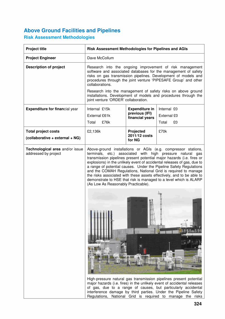
324
Above Ground Facilities and Pipelines
Risk Assessment Methodologies
Project title Risk Assessment Methodologies for Pipelines and AGIs
Project Engineer Dave McCollum
Description of project Research into the ongoing improvement of risk management software and associated databases for the management of safety risks on gas transmission pipelines. Development of models and procedures through the joint venture ‘PIPESAFE Group’ and other collaborations.
Research into the management of safety risks on above ground installations. Development of models and procedures through the joint venture ‘ORDER’ collaboration.
Expenditure for financial year Internal £15k
External £61k
Total £76k
Expenditure in previous (IFI) financial years
Internal £0
External £0
Total £0
Total project costs
(collaborative + external + NG)
£2,136k Projected 2011/12 costs for NG
£70k
Technological area and/or issue addressed by project
Above-ground installations or AGIs (e.g. compressor stations, terminals, etc.) associated with high pressure natural gas transmission pipelines present potential major hazards (i.e. fires or explosions) in the unlikely event of accidental releases of gas, due to a range of potential causes. Under the Pipeline Safety Regulations and the COMAH Regulations, National Grid is required to manage the risks associated with these assets effectively, and to be able to demonstrate to HSE that risk is managed to a level which is ALARP (As Low As Reasonably Practicable).
High-pressure natural gas transmission pipelines present potential major hazards (i.e. fires) in the unlikely event of accidental releases of gas, due to a range of causes, but particularly accidental interference damage by third parties. Under the Pipeline Safety Regulations, National Grid is required to manage the risks
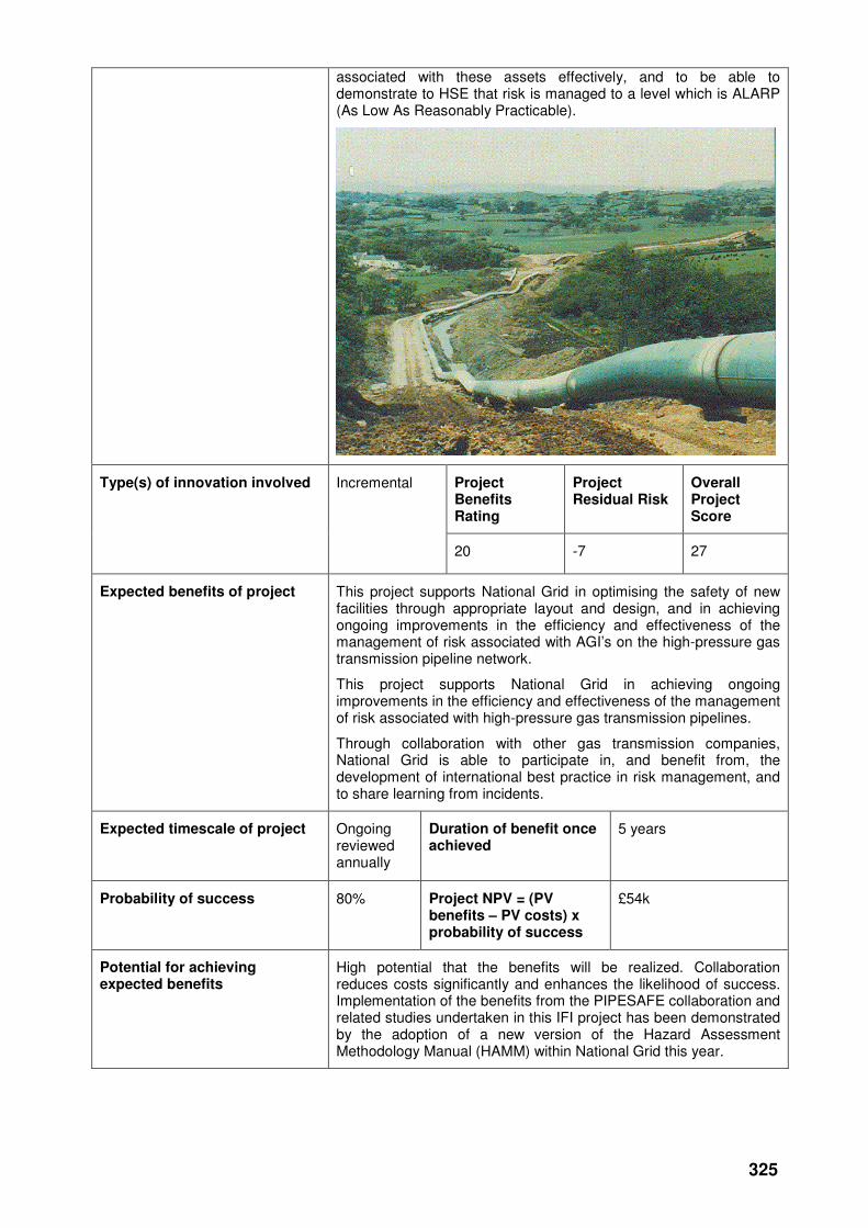
325
associated with these assets effectively, and to be able to demonstrate to HSE that risk is managed to a level which is ALARP (As Low As Reasonably Practicable).
Project Benefits Rating
Project Residual Risk
Overall Project Score
Type(s) of innovation involved Incremental
20 -7 27
Expected benefits of project This project supports National Grid in optimising the safety of new facilities through appropriate layout and design, and in achieving ongoing improvements in the efficiency and effectiveness of the management of risk associated with AGI’s on the high-pressure gas transmission pipeline network.
This project supports National Grid in achieving ongoing improvements in the efficiency and effectiveness of the management of risk associated with high-pressure gas transmission pipelines.
Through collaboration with other gas transmission companies, National Grid is able to participate in, and benefit from, the development of international best practice in risk management, and to share learning from incidents.
Expected timescale of project Ongoing reviewed annually
Duration of benefit once achieved
5 years
Probability of success 80% Project NPV = (PV benefits – PV costs) x probability of success
£54k
Potential for achieving expected benefits
High potential that the benefits will be realized. Collaboration reduces costs significantly and enhances the likelihood of success. Implementation of the benefits from the PIPESAFE collaboration and related studies undertaken in this IFI project has been demonstrated by the adoption of a new version of the Hazard Assessment Methodology Manual (HAMM) within National Grid this year.
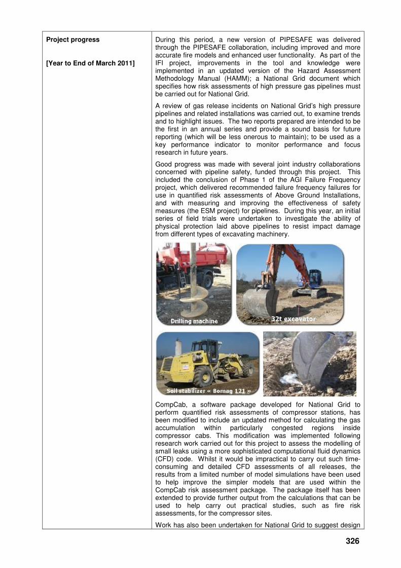
326
Project progress
[Year to End of March 2011]
During this period, a new version of PIPESAFE was delivered through the PIPESAFE collaboration, including improved and more accurate fire models and enhanced user functionality. As part of the IFI project, improvements in the tool and knowledge were implemented in an updated version of the Hazard Assessment Methodology Manual (HAMM); a National Grid document which specifies how risk assessments of high pressure gas pipelines must be carried out for National Grid.
A review of gas release incidents on National Grid’s high pressure pipelines and related installations was carried out, to examine trends and to highlight issues. The two reports prepared are intended to be the first in an annual series and provide a sound basis for future reporting (which will be less onerous to maintain); to be used as a key performance indicator to monitor performance and focus research in future years.
Good progress was made with several joint industry collaborations concerned with pipeline safety, funded through this project. This included the conclusion of Phase 1 of the AGI Failure Frequency project, which delivered recommended failure frequency failures for use in quantified risk assessments of Above Ground Installations, and with measuring and improving the effectiveness of safety measures (the ESM project) for pipelines. During this year, an initial series of field trials were undertaken to investigate the ability of physical protection laid above pipelines to resist impact damage from different types of excavating machinery.
CompCab, a software package developed for National Grid to perform quantified risk assessments of compressor stations, has been modified to include an updated method for calculating the gas accumulation within particularly congested regions inside compressor cabs. This modification was implemented following research work carried out for this project to assess the modelling of small leaks using a more sophisticated computational fluid dynamics (CFD) code. Whilst it would be impractical to carry out such time-consuming and detailed CFD assessments of all releases, the results from a limited number of model simulations have been used to help improve the simpler models that are used within the CompCab risk assessment package. The package itself has been extended to provide further output from the calculations that can be used to help carry out practical studies, such as fire risk assessments, for the compressor sites.
Work has also been undertaken for National Grid to suggest design
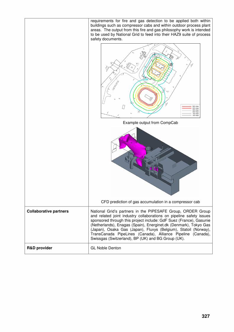
327
requirements for fire and gas detection to be applied both within buildings such as compressor cabs and within outdoor process plant areas. The output from this fire and gas philosophy work is intended to be used by National Grid to feed into their HAZ9 suite of process safety documents.
500 mbar
400 mbar300 mbar
200 mbar
150 mbar100 mbar
Example output from CompCab
CFD prediction of gas accumulation in a compressor cab
Collaborative partners National Grid’s partners in the PIPESAFE Group, ORDER Group and related joint industry collaborations on pipeline safety issues sponsored through this project include: GdF Suez (France), Gasunie (Netherlands), Enagas (Spain), Energinet.dk (Denmark), Tokyo Gas (Japan), Osaka Gas (Japan), Fluxys (Belgium), Statoil (Norway), TransCanada PipeLines (Canada), Alliance Pipeline (Canada), Swissgas (Switzerland), BP (UK) and BG Group (UK).
R&D provider GL Noble Denton
328
Ageing valve research
Project title Plumley Block Valve Removal
Project Engineer Steve Johnstone
Description of project Research into factors affecting valve condition within pits. This information will be used as evidence for helping the business to determine valve technical asset lives and updating Maintenance Policy where appropriate.
Expenditure for financial year Internal £6k
External £3k
Total £8k
Expenditure in previous (IFI) financial years
Internal £8k
External £145k
Total £153k
Total project costs
(collaborative + external + NG)
£161k Projected 2011/12 costs for NG
£ 0
Technological area and/or issue addressed by project
An opportunity has arisen to remove a pit-installed, life-expired block valve from service. This will allow further detailed condition analysis on a typical block valve installation, where the output from these findings will provide evidence to the business on Technical Asset Lives for valves installed within pits and where appropriate update Maintenance Policy.
Project Benefits Rating
Project Residual Risk
Overall Project Score
Type(s) of innovation involved Incremental
18 1 17
Expected benefits of project If an ageing block valve fails closed, it can negatively affect the security of the energy supply. If an ageing block valve fails open, it could significantly increase the severity of a pipeline failure incident. Ageing block valves are also responsible for unplanned emissions of natural gas (including 85-93% methane, which is a greenhouse gas) into the atmosphere.
National Grid is therefore considering replacement or repair of these assets, together with methods to prioritise such actions. This project will develop and evaluate prioritisation models and new techniques for conducting repairs, rather than replacing them.
Cost to repair this type of asset = £100k
Cost to replace this type of asset with new = £200k
66 Block valve sites in pits x difference between repair/replace (£100k) = £6.6M potential cost saving.
Expected timescale of project 2 years Duration of benefit once achieved
5 years
Probability of success 60% Project NPV = (PV benefits – PV costs) x probability of success
£263k
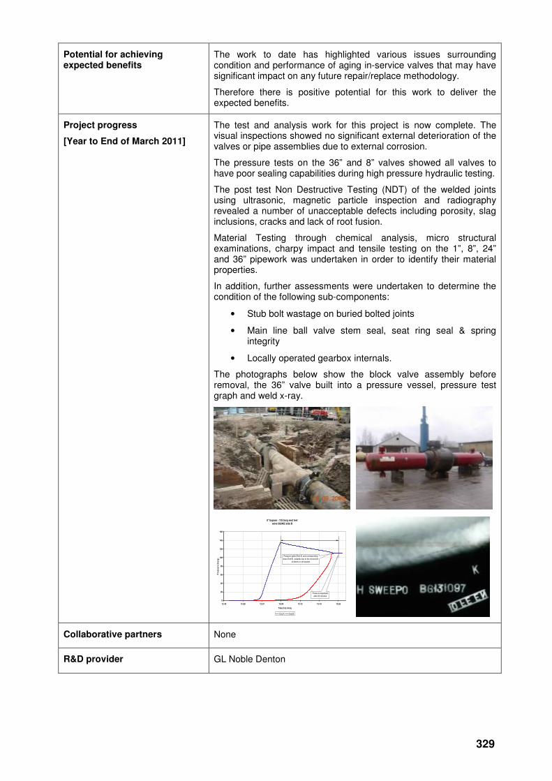
329
Potential for achieving expected benefits
The work to date has highlighted various issues surrounding condition and performance of aging in-service valves that may have significant impact on any future repair/replace methodology.
Therefore there is positive potential for this work to deliver the expected benefits.
Project progress
[Year to End of March 2011]
The test and analysis work for this project is now complete. The visual inspections showed no significant external deterioration of the valves or pipe assemblies due to external corrosion.
The pressure tests on the 36” and 8” valves showed all valves to have poor sealing capabilities during high pressure hydraulic testing.
The post test Non Destructive Testing (NDT) of the welded joints using ultrasonic, magnetic particle inspection and radiography revealed a number of unacceptable defects including porosity, slag inclusions, cracks and lack of root fusion.
Material Testing through chemical analysis, micro structural examinations, charpy impact and tensile testing on the 1”, 8”, 24” and 36” pipework was undertaken in order to identify their material properties.
In addition, further assessments were undertaken to determine the condition of the following sub-components:
• Stub bolt wastage on buried bolted joints
• Main line ball valve stem seal, seat ring seal & spring integrity
• Locally operated gearbox internals.
The photographs below show the block valve assembly before removal, the 36” valve built into a pressure vessel, pressure test graph and weld x-ray.
8" bypass - 135 barg seat test
valve 362402 side B
0
20
40
60
80
100
120
140
160
12:43 12:50 12:57 13:04 13:12 13:19 13:26
Time (hrs:mins)
Pre
ss
ure
(b
arg
)
End A End B
Pressure equalised
after 23 minutes
Pressure spike (End A) and corresponding
drop (End B), possibly due to the movement
of debris or old sealant
Collaborative partners None
R&D provider GL Noble Denton
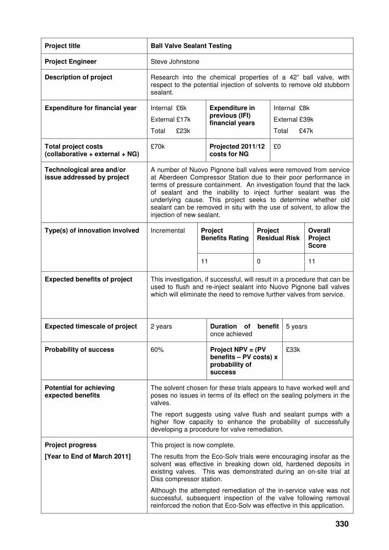
330
Project title Ball Valve Sealant Testing
Project Engineer Steve Johnstone
Description of project Research into the chemical properties of a 42” ball valve, with respect to the potential injection of solvents to remove old stubborn sealant.
Expenditure for financial year Internal £6k
External £17k
Total £23k
Expenditure in previous (IFI) financial years
Internal £8k
External £39k
Total £47k
Total project costs (collaborative + external + NG)
£70k Projected 2011/12 costs for NG
£0
Technological area and/or issue addressed by project
A number of Nuovo Pignone ball valves were removed from service at Aberdeen Compressor Station due to their poor performance in terms of pressure containment. An investigation found that the lack of sealant and the inability to inject further sealant was the underlying cause. This project seeks to determine whether old sealant can be removed in situ with the use of solvent, to allow the injection of new sealant.
Project Benefits Rating
Project Residual Risk
Overall Project Score
Type(s) of innovation involved Incremental
11 0 11
Expected benefits of project This investigation, if successful, will result in a procedure that can be used to flush and re-inject sealant into Nuovo Pignone ball valves which will eliminate the need to remove further valves from service.
Expected timescale of project 2 years Duration of benefit once achieved
5 years
Probability of success 60% Project NPV = (PV benefits – PV costs) x probability of success
£33k
Potential for achieving expected benefits
The solvent chosen for these trials appears to have worked well and poses no issues in terms of its effect on the sealing polymers in the valves.
The report suggests using valve flush and sealant pumps with a higher flow capacity to enhance the probability of successfully developing a procedure for valve remediation.
Project progress
[Year to End of March 2011]
This project is now complete.
The results from the Eco-Solv trials were encouraging insofar as the solvent was effective in breaking down old, hardened deposits in existing valves. This was demonstrated during an on-site trial at Diss compressor station.
Although the attempted remediation of the in-service valve was not successful, subsequent inspection of the valve following removal reinforced the notion that Eco-Solv was effective in this application.

331
Eco-Solv pumping rates/velocities have been identified for future investigation, as it appeared that the lack of capacity in this area was a reason why Eco-Solv injection performance was disappointing during both the workshop and on-site tests.
In addition, to assist with the Eco-Solv retention within the ball valve seat ring and increase the solvent contact time it has been suggested it would be worthwhile investigating whether the Eco-Solv product could be manufactured into a gel prior to any further injection trials.
Collaborative partners None
R&D provider GL Noble Denton
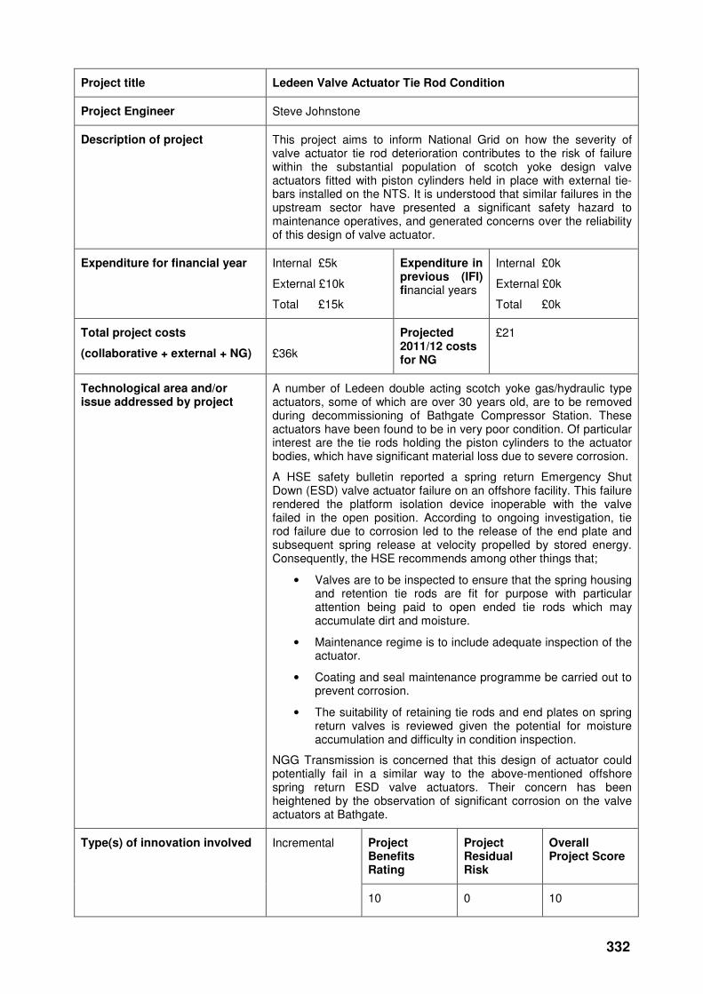
332
Project title Ledeen Valve Actuator Tie Rod Condition
Project Engineer Steve Johnstone
Description of project This project aims to inform National Grid on how the severity of valve actuator tie rod deterioration contributes to the risk of failure within the substantial population of scotch yoke design valve actuators fitted with piston cylinders held in place with external tie-bars installed on the NTS. It is understood that similar failures in the upstream sector have presented a significant safety hazard to maintenance operatives, and generated concerns over the reliability of this design of valve actuator.
Expenditure for financial year Internal £5k
External £10k
Total £15k
Expenditure in previous (IFI) financial years
Internal £0k
External £0k
Total £0k
Total project costs
(collaborative + external + NG)
£36k
Projected 2011/12 costs for NG
£21
Technological area and/or issue addressed by project
A number of Ledeen double acting scotch yoke gas/hydraulic type actuators, some of which are over 30 years old, are to be removed during decommissioning of Bathgate Compressor Station. These actuators have been found to be in very poor condition. Of particular interest are the tie rods holding the piston cylinders to the actuator bodies, which have significant material loss due to severe corrosion.
A HSE safety bulletin reported a spring return Emergency Shut Down (ESD) valve actuator failure on an offshore facility. This failure rendered the platform isolation device inoperable with the valve failed in the open position. According to ongoing investigation, tie rod failure due to corrosion led to the release of the end plate and subsequent spring release at velocity propelled by stored energy. Consequently, the HSE recommends among other things that;
• Valves are to be inspected to ensure that the spring housing and retention tie rods are fit for purpose with particular attention being paid to open ended tie rods which may accumulate dirt and moisture.
• Maintenance regime is to include adequate inspection of the actuator.
• Coating and seal maintenance programme be carried out to prevent corrosion.
• The suitability of retaining tie rods and end plates on spring return valves is reviewed given the potential for moisture accumulation and difficulty in condition inspection.
NGG Transmission is concerned that this design of actuator could potentially fail in a similar way to the above-mentioned offshore spring return ESD valve actuators. Their concern has been heightened by the observation of significant corrosion on the valve actuators at Bathgate.
Project Benefits Rating
Project Residual Risk
Overall Project Score
Type(s) of innovation involved Incremental
10 0 10
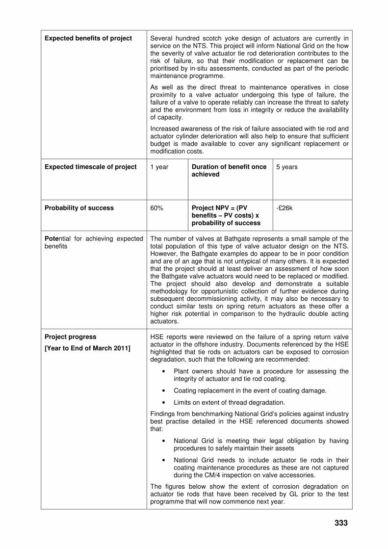
333
Expected benefits of project Several hundred scotch yoke design of actuators are currently in service on the NTS. This project will inform National Grid on the how the severity of valve actuator tie rod deterioration contributes to the risk of failure, so that their modification or replacement can be prioritised by in-situ assessments, conducted as part of the periodic maintenance programme.
As well as the direct threat to maintenance operatives in close proximity to a valve actuator undergoing this type of failure, the failure of a valve to operate reliably can increase the threat to safety and the environment from loss in integrity or reduce the availability of capacity.
Increased awareness of the risk of failure associated with tie rod and actuator cylinder deterioration will also help to ensure that sufficient budget is made available to cover any significant replacement or modification costs.
Expected timescale of project 1 year Duration of benefit once achieved
5 years
Probability of success 60% Project NPV = (PV benefits – PV costs) x probability of success
-£26k
Potential for achieving expected benefits
The number of valves at Bathgate represents a small sample of the total population of this type of valve actuator design on the NTS. However, the Bathgate examples do appear to be in poor condition and are of an age that is not untypical of many others. It is expected that the project should at least deliver an assessment of how soon the Bathgate valve actuators would need to be replaced or modified. The project should also develop and demonstrate a suitable methodology for opportunistic collection of further evidence during subsequent decommissioning activity, it may also be necessary to conduct similar tests on spring return actuators as these offer a higher risk potential in comparison to the hydraulic double acting actuators.
Project progress
[Year to End of March 2011]
HSE reports were reviewed on the failure of a spring return valve actuator in the offshore industry. Documents referenced by the HSE highlighted that tie rods on actuators can be exposed to corrosion degradation, such that the following are recommended:
• Plant owners should have a procedure for assessing the integrity of actuator and tie rod coating.
• Coating replacement in the event of coating damage.
• Limits on extent of thread degradation.
Findings from benchmarking National Grid’s policies against industry best practise detailed in the HSE referenced documents showed that:
• National Grid is meeting their legal obligation by having procedures to safely maintain their assets
• National Grid needs to include actuator tie rods in their coating maintenance procedures as these are not captured during the CM/4 inspection on valve accessories.
The figures below show the extent of corrosion degradation on actuator tie rods that have been received by GL prior to the test programme that will now commence next year.
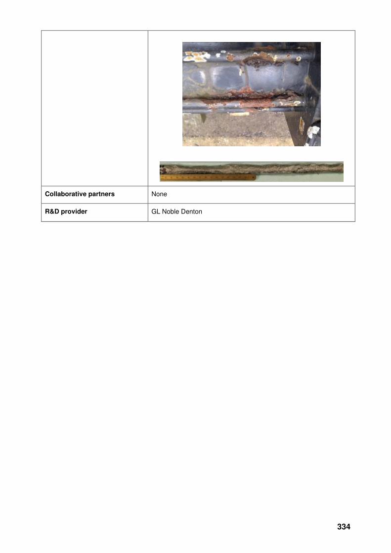
334
Collaborative partners None
R&D provider GL Noble Denton
335
Methane Emissions
Project title Alternatives to Venting from the NTS Gas Transmission System
Project Engineer Ian Briggs
Description of project The key objective of this study is to develop practical methods to reduce the emissions of methane that would otherwise occur during venting to the atmosphere from the natural gas transmission network.
Expenditure for financial year Internal £9k
External £211k
Total £220k
Expenditure in previous (IFI) financial years
Internal £9k
External £174k
Total £183k
Total project costs
(collaborative + external + NG)
£965k Projected 2011/12 costs for NG
£562k
Technological area and/or issue addressed by project
Natural gas, which is typically 85-93% methane, is released to the environment from gas transmission networks in a number of ways, including:
• Infrastructure containment failures (e.g. elastomer seals, small bore pipework connections, pipework failures)
• Operational venting for decommission/repair or extension of networks
• Process venting from equipment (planned and unplanned)
• Fugitive leakage from pipeline equipment.
Venting and fugitive leakage constitutes a significant part of the overall methane losses to atmosphere. Fugitive leakage from the NTS has been estimated to be of the order of 4000 tonnes per annum. Although this project will not address fugitive emissions, the figure is given here to compare with operational venting of methane (i.e. planned venting for maintenance or automated venting of compressor units during emergency shutdowns).
Planned venting can arise from a number of sources around the network, including venting at compressor sites and pipeline decommissioning prior to repairs, replacement or modification activity.
Planned venting at compressor sites is monitored and recorded through the on-line control system. For 2007, NTS reported to the Environment Agencies that there had been 1887 tonnes of natural gas emitted by planned vented from compressor stations.
Pipeline pressure is typically reduced to 7barg by recompressing it into an adjacent pipeline. However, the last 7barg can not be sensibly recompressed using the available equipment. It is therefore safely vented to atmosphere. Historical trends suggest that in excess of 150,000m
3 of pipework volume is vented to atmosphere in
this way each year (about 1000 tonnes of gas).
Clearly there are sound environmental and energy efficiency reasons for developing methods to reduce the amount of vented natural gas. There are several points that influence the current venting best practice, including both commercial and operational factors in addition to energy saving and environmental concerns. These concerns include the consideration of:
• Distance between pipeline block valves. These isolation distances are tending to increase and thus lead to increased
336
vented volumes during decommissioning.
• Installation of Booster Units at Pig Trap or Block Valve Sites to enable better management of the decommissioning activities.
To improve the environmental performance of final stages of the decommissioning process several options are available including:
• Collect the gas and use elsewhere with the network.
• Flare the gas. Methane is recognised as having a significantly greater “Global Warming Potential” (GWP) than carbon dioxide, approximately twenty times. Thus flaring will reduce the environmental impact.
• Use the gas at the decommissioning site.
Project Benefits Rating
Project Residual Risk
Overall Project Score
Type(s) of innovation involved Radical
18 -1 19
Expected benefits of project The benefits from undertaking this work include:
• Development of new best practice for lowering methane emissions during decommissioning activities prior to maintenance
• Reduction in National Grid’s methane emission inventory
• Improved energy management.
A financial benefit can be derived from consideration of reduced methane emissions. CO2 emissions are currently traded at £25/tonne. Natural gas emissions are recognised to be twenty times more damaging to the environment, such that £500/tonne might be expected when methane is added to the European Emissions Trading Scheme.
Planned venting down of gas transmission pipelines for maintenance accounts for about 960 tonnes of methane emissions per year (£480,000 per year).
Operational venting down of NTS compressor units during emergency scenarios and for maintenance accounts for more than 1800 tonnes (Advantica Report 6446) of methane emissions per year (£900,000 per year).
If the gas can be captured, stored and used to fuel generators to provide 5kWe/tonne, and we assume that the cost of bought-in electricity is 8p per kW-hr:
• Alternatives to pipeline venting operations could provide a proportion of 8760 hours * 500kWe * 8p = £350,000
• Alternatives to compressor venting could provide a proportion of (1800 / 960) * £350,000 = £552,000
Expected timescale of project 4 years Duration of benefit once achieved
Lifetime
Probability of success 60% Project NPV = (PV benefits – PV costs) x probability of
£655k
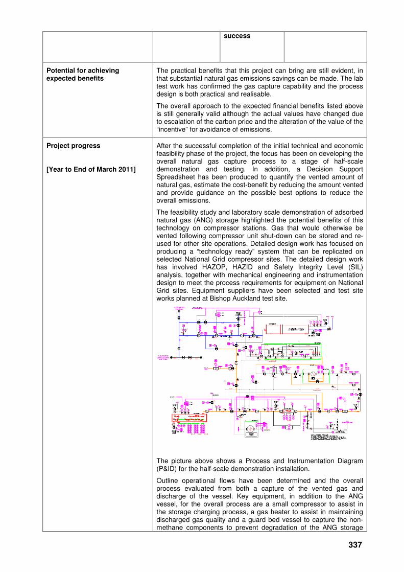
337
success
Potential for achieving expected benefits
The practical benefits that this project can bring are still evident, in that substantial natural gas emissions savings can be made. The lab test work has confirmed the gas capture capability and the process design is both practical and realisable.
The overall approach to the expected financial benefits listed above is still generally valid although the actual values have changed due to escalation of the carbon price and the alteration of the value of the “incentive” for avoidance of emissions.
Project progress
[Year to End of March 2011]
After the successful completion of the initial technical and economic feasibility phase of the project, the focus has been on developing the overall natural gas capture process to a stage of half-scale demonstration and testing. In addition, a Decision Support Spreadsheet has been produced to quantify the vented amount of natural gas, estimate the cost-benefit by reducing the amount vented and provide guidance on the possible best options to reduce the overall emissions.
The feasibility study and laboratory scale demonstration of adsorbed natural gas (ANG) storage highlighted the potential benefits of this technology on compressor stations. Gas that would otherwise be vented following compressor unit shut-down can be stored and re-used for other site operations. Detailed design work has focused on producing a “technology ready” system that can be replicated on selected National Grid compressor sites. The detailed design work has involved HAZOP, HAZID and Safety Integrity Level (SIL) analysis, together with mechanical engineering and instrumentation design to meet the process requirements for equipment on National Grid sites. Equipment suppliers have been selected and test site works planned at Bishop Auckland test site.
The picture above shows a Process and Instrumentation Diagram (P&ID) for the half-scale demonstration installation.
Outline operational flows have been determined and the overall process evaluated from both a capture of the vented gas and discharge of the vessel. Key equipment, in addition to the ANG vessel, for the overall process are a small compressor to assist in the storage charging process, a gas heater to assist in maintaining discharged gas quality and a guard bed vessel to capture the non-methane components to prevent degradation of the ANG storage

338
capability.
The design phase is now nearing completion, orders for long-lead-time equipment have been placed and test site readiness is being assessed to enable the detailed test work and performance evaluation of the process to be undertaken.
In parallel with the ANG demonstration work, a Decision Support Spreadsheet has been developed to enable users to calculate the amount of gas that could be vented, and the environmental and cost implications for this activity.
The Spreadsheet can be used for a number gas industry operations including Compressor venting, venting from Pipeline maintenance and repair, and venting from smaller-scale activities like PIG trap or filter maintenance. The Spreadsheet highlights the potential emission avoided through use of different technologies and enables users to assess the best options for specific sites or operations. It is currently undergoing final testing before distribution to the National Grid Project Steering Committee for evaluation.
Collaborative partners None
R&D provider GL Noble Denton
339
Reducing risks
Project title Geotechnics
Project Engineers Alan Hodder / Brian Woodhouse
Description of project Research into (i) “static” soil restraint to buried pipework and (ii) vibration behaviour of buried pipework.
Expenditure for financial year Internal £6k
External £17k
Total £23k
Expenditure in previous (IFI) financial years
Internal £13k
External £71k
Total £83k
Total project costs
(collaborative + external + NG)
£106k Projected 2011/12 costs for NG
£0
Technological area and/or issue addressed by project
The aims of this research and development project were to reduce uncertainty in the evaluation of soil restraint to, and vibration behaviour of, buried pipework and thus improve confidence in the stress analysis of pipework, thereby enhancing safety, supply reliability and cost efficiency in the design and maintenance of the gas transmission pipeline systems. This has been done by:-
• reviewing previous corporate recommended practice for the evaluation of static soil restraint parameters used in pipework stress analysis in the light of additional published test data and restraint prediction theories, and
• investigating the response of buried pipework to vibration and developing design guidance to mitigate failure risk, noting previous instances of fatigue failure in small bore “stabbing” connections.
The outputs from the project will be used to enhance design guidance for incorporation into company specifications and contract for new-build assets and for the assessment or modification of existing assets.
The work included in this project is now complete and the results are under review within National Grid to assess (i) needs for additional work and (ii) revisions to corporate design/analysis specifications and practice.
(Note: The original scope included assessment of permissible pipe strain criteria but explicit project needs meant this work was accelerated and covered elsewhere.)
Project Benefits Rating
Project Residual Risk
Overall Project Score
Type(s) of innovation involved Tech Transfer
9 3 6
Expected benefits of project This research has provided both (i) substantial improvements in the ‘confidence level’ in the evaluation of buried pipework soil restraint and (ii) significant data, knowledge and consequent design guidance for the avoidance/reduction of vibration fatigue failures on buried pipework.
The additional data and knowledge gained will directly feed into improved design and analysis practices and hence contribute to enhanced safety, supply reliability and cost efficiency of the high-pressure gas transmission system. Example consequential benefits
340
include:
• Increased scope for pressure up-rating of pipelines, less conservative designs on new pipeline installations, reduced costs of remediation, protection and replacement of steel pipelines. (Where the pipe stress outputs is more favourable than before the project),
• Reduction in failure risk (especially from fatigue effects) both from new-build or modification projects and from more reliable prediction of intervention needs and timing on pipelines subject to ground movement and/or defective existing assets. (Where the pipe stress outputs is less favourable than before the project).
In all cases, the project outputs contribute to the maintenance and continued development of pipeline safety standards to satisfy company requirements and give confidence to others (e.g. HSE, public at large).
The development of design guidance packages to incorporate the knowledge gained into future work will ensure ‘consistency’ of best practice across the company and thus satisfy a primary HSE concern.
Expected timescale of project 4 years Duration of benefit once achieved
5 years
Probability of success 60% Project NPV = (PV benefits – PV costs) x probability of success
£-9k
Potential for achieving expected benefits
The project was essentially completed in 2009/10. The project was kept open in early 2010/11 to allow time for final reviews of the project reports.
Project progress
[Year to End of March 2011]
1) “Static” soil restraint:-
The Soil Restraint Calculator spreadsheet tool, developed by the project allows the stiffness, ultimate load and ultimate displacement of soil restraint (to buried pipework) to be readily evaluated in the axial, lateral, downward and uplift direction for both granular and cohesive soils (of varying densities/strength).
2) Vibration behaviour of buried pipework::
Soil damping levels determined in all tests on the vibration behaviour of buried pipework were consistent with commonly published ranges. The work has given a useful insight into the vibration behaviour of buried pipework and will facilitate improved design and installation practice. Further work may be considered, notably with respect to the effects of (historical) ‘soft fill’ around below-ground stabbings and the variation in vibration response which may arise as backfill characteristics change over the life of an installation (e.g. due to self-weight consolidation or rainwater percolation).
Collaborative partners None
R&D provider GL Noble Denton
Pipeline Maintenance Centre
341
Project title Development of improved suction pipework filtration methods for compressors
Project Engineer Brian Woodhouse
Description of project Develop an understanding of the mechanisms that cause vibration in strainers at compressor stations.
Establish the sensitivity of the vibration and pressure drop to key design parameters.
Identify a preferred configuration of filtration for adoption on the NTS.
The concept of using a computational fluid dynamics (CFD) model of a suction strainer to determine the optimal strainer design has been dropped in favour of practical reviews of the mechanical design, best practice, operational issues and consideration of other gas cleaning equipment types.
One or more of a number of experimental and/or modelling options may be beneficial before embarking on the project implementation.
Expenditure for financial year Internal £5k
External £15k
Total £19k
Expenditure in previous (IFI) financial years
Internal £9k
External £51k
Total £60k
Total project costs
(collaborative + external + NG)
£80k Projected 2011/12 costs for NG
£0
Technological area and/or issue addressed by project
The use of a strainer carries a number of risks and uncertainties that are associated with the flow of the gas through the device. These include:
• The risk of vibration failure of the strainer itself or adjacent components, including small-bore pipework or the compressor.
• The potential for large pressure drop which will waste fuel and can account for a significant percentage of the whole fuel cost for the site.
• The potential for the strainer to be a major source of noise pollution.
• Lack of clear guidance as to whether suction strainers should only be temporarily installed during commissioning, or considered permanent.
Project Benefits Rating
Project Residual Risk
Overall Project Score
Type(s) of innovation involved Significant
13 1 12
Expected benefits of project Fewer failures associated with strainers at compressor stations – reduced OPEX for repairs of compressors and pipework.
Less pressure drop across compressor – reduced OPEX and emissions. There are some sites where the power dissipated by the strainer is thought to account for about 10% of the fuel consumption of the compressor. Improved selection of strainers for different applications – appropriate filtration.
342
Expected timescale of project 2 year Duration of benefit once achieved
5 years
Probability of success 60% Project NPV = (PV benefits – PV costs) x probability of success
£145k
Potential for achieving expected benefits
To establish the level of protection required of a compressor installation and to identify the requirements which would achieve that level of protection. This could remove the need for strainers thus removing the risk of their failure and subsequent damage to the compressor plant which results in station outages.
Project progress
[Year to End of March 2011]
The initial CFD modelling of flow and pressure drop through a strainer proved interesting, however when attempting to scale the model up to a relevant size this approach proved not to be cost effective and has been stopped.
The alternative approach was therefore to carry out a bench marking exercise and mechanical design review that identified the critical filtration requirements as defined by the compressor vendors, reviewed of the design and construction philosophies adopted by strainer manufacturers, and explored of the filtration practices adopted by several European gas network operators.
The second stage of this programme of work comprised a workshop (carried out in July 2010) where the critical filtration system design and operational issues identified from the first stage were discussed by key parties from National Grid and GL Noble Denton. A strategy for the specification and selection of filtration systems was also discussed and is presented within this report.
The key recommendations from this work were that the preferred solution for compressor filtration, for normal station operation, is to install centrifugal separators on the station inlet, and in-line strainers in the unit suction pipework for commissioning and initial operation purposes only. A reduced filtration efficiency station system could be installed as a secondary arrangement if it is able to offer a cost saving benefit compared to additional centrifugal devices.
Work is underway to update National Grid Procedures and Specifications in line with the recommendations of this report.
Collaborative partners None
R&D provider GL Noble Denton
343
Above ground Facilities
Reducing Risk
Project title Installation of IRIS separators [at Carnforth Compressor Station].
Project Engineer Paul Sinclair
Description of project Install IRIS separators in the fuel gas supplies of A and B Compressor Units.
Expenditure for financial year Internal £9k
External £131k
Total £140k
Expenditure in previous (IFI) financial years
Internal £20k
External £76k
Total £96k
Total project costs
(collaborative + external + NG)
£247k
Projected 2011/12 costs for NG
£11k
Technological area and/or issue addressed by project
To trial the use of a rotary separator that will easily remove liquid contaminants form the fuel gas supply, thus increasing the efficiency and life of the gas generators.
Project Benefits Rating
Project Residual Risk
Overall Project Score
Type(s) of innovation involved Tech Transfer
11 1 10
Expected benefits of project To remove liquid contaminants form the gas supply providing the fuel to the gas generators thus increasing the efficiency and life of the gas generators. Monitoring the amount of liquid removed will determine the success of the scheme. Monitoring the amount of liquid removed will determine the success of the scheme.
Expected timescale of project 4 years Duration of benefit once achieved
5 years
Probability of success 60% Project NPV = (PV benefits – PV costs) x probability of success
£27k
Potential for achieving expected benefits
There is a high likelihood that the IRIS filters will remove liquids, if they are present. The remaining uncertainties are whether all significant liquid contaminants would be removed from the fuel lines; and whether this will lead to a detectable reduction in major overhaul frequency for the gas turbine engines.
Project progress
[Year to End of March 2011]
The two IRIS separators are ready to be installed at Carnforth compressor station. Following completion of the design work, a further amount of funding will be required to complete the installation. The amount has yet to be confirmed.

344
Collaborative partners None
R&D provider Dresser Rand
345
Project title Advances in Compressor Pipework Vibration Monitoring and Effectiveness of Instrument Stabbing Encapsulation to Reduce Vibration Response
Project Engineer Brian Woodhouse
Description of project 1. Advances in Compressor Pipework Vibration Monitoring Surveys
This project will evaluate how recent technological advances can be used to improve the reliability and performance of long-term vibration monitoring on compressor station pipework, while reducing the cost and increasing the safety of such operations.
Vibration monitoring surveys are used by National Grid to identify high pressure pipework attachments that may fail if remedial action is not taken. Such failures can be RIDDOR-reportable because they can involve a large uncontrolled release of natural gas at high pressure into the surrounding environment.
2. Effectiveness of Instrument Stabbing Encapsulation to Reduce Vibration Response
This project aims to prove that a convenient encapsulation technique (which has so far only been applied on a temporary trial basis) can be considered as a permanent approved mitigation measure against fatigue failure that would otherwise result as a response to nearby vibration sources.
Expenditure for financial year Internal £4k
External £10k
Total £14k
Expenditure in previous (IFI) financial years
Internal £2k
External £114k
Total £115k
Total project costs (collaborative + external + NG)
£129k Projected 2011/12 costs for NG
£0
Technological area and/or issue addressed by project
Vibration of instrument stabbings and other pipework at National Grid’s compressor stations and terminals has previously given rise to fatigue failures, and a large programme of work has been undertaken to modify pipework identified as being at risk. As part of this work, pipework vibration monitoring at National Grid’s compressor stations and terminals has been used to assess the risk of fatigue failure following any incidents, and as part of a screening exercise. Where the risk is high, remedial action has been taken to reduce the risk.
Project Benefits Rating
Project Residual Risk
Overall Project Score
Type(s) of innovation involved Significant
15 -1 16
Expected benefits of project National Grid currently spends approximately £200k per annum conducting long-term surveys of vibration on 4 compressor stations. This is likely to continue for the next 3-4 years. It is possible that this annual cost could be reduced to some degree by the introduction of new technology. However, such savings would likely not cover the cost of purchasing the new equipment. Bigger savings would be expected to come from improvements to either the quality or reliability of the resulting surveys, or the number of stations that could be surveyed simultaneously (or perhaps even permanently).
A validated method for use on identified ‘at-risk’ stabbings to

346
mitigate high vibration, and which can be easily implemented with minimal disruption of station operations, will be of significant benefit and offer savings in the time and expenditure required for design and installation.
Expected timescale of project 2 years Duration of benefit once achieved
5 years
Probability of success 60% Project NPV = (PV benefits – PV costs) x probability of success
£27k
Potential for achieving expected benefits
Finding a monitoring system that can replace the current surveys has a medium chance of success due to the cost that may be involved with the role out of the monitoring system.
The initial findings of the small number of early trials of the stabbing encapsulation technique suggest that detailed investigation of the behaviour has a high chance of success.
Project progress
[Year to End of March 2011]
Part 1 - This project has looked at ten different sensor technologies, and a detailed review of their capabilities undertaken including a cost benefit analysis of the different systems.
In addition to the different techniques the different communication media were also investigated, ranging from fibre-optic to wireless local area network (WLAN). From the ten techniques assessed, three have been proposed to be taken forward for technological trial, with the intention of determining their true effectiveness in the field.
The project scope has been updated following evidence of high electrical noise interference being present on some sites, which has prevented field trials to be completed satisfactorily.
Part 2 - The test rig for the stabbing section of this project has been constructed and the testing of un-encapsulated and encapsulated stabbings has been completed. The study has shown that encapsulation proves a successful long-term measure for mitigating high levels of vibration. Testing with failed bonding of the encapsulation to the stabbing also proved that the technique still had an effective mitigating influence on the pipework vibration.
A National Grid work procedure is in final stages of completion.
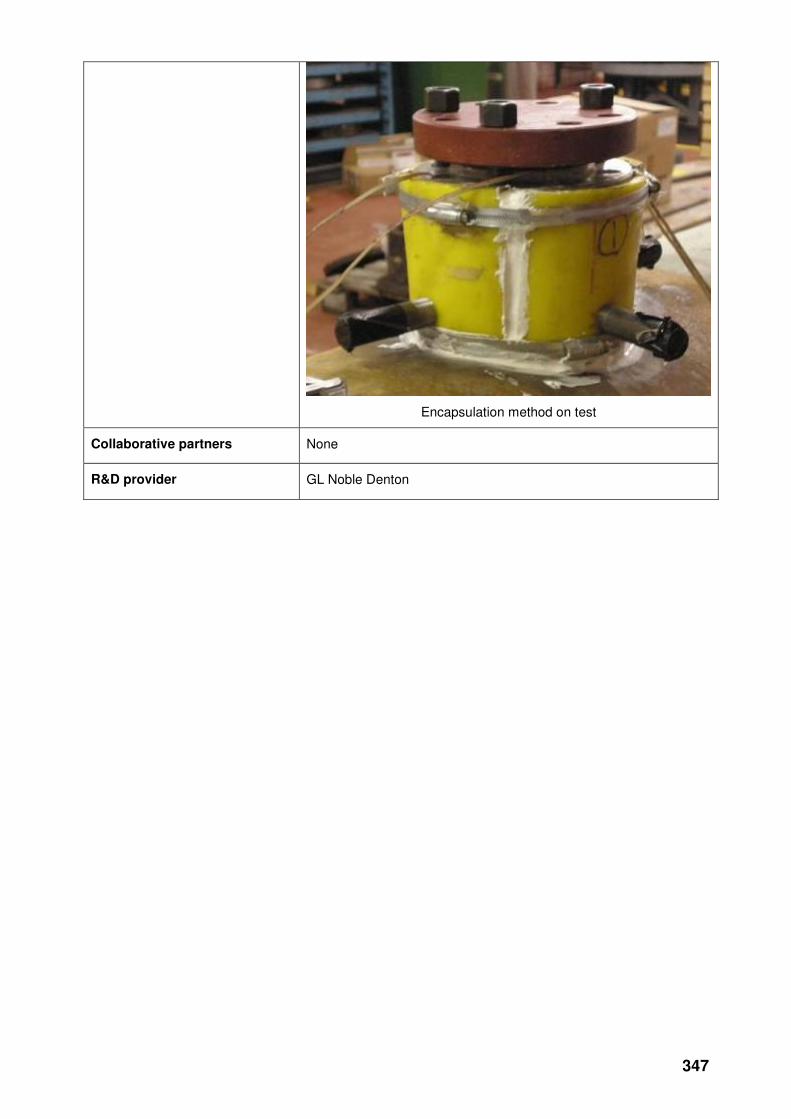
347
Encapsulation method on test
Collaborative partners None
R&D provider GL Noble Denton
348
Environmental Impact
Project title Environmental Study for Future Above Ground Facility Developments
Project Engineer Neil Dawson
Description of project
This project aims to identify what needs to be considered (in 2009 and the next 7-years) during the design of above ground installations (i.e. offtakes, multi-junctions, block valve sites and compressor facilities), if the design objective is changed from simple least cost to pursue an ambition to create the least environmentally damaging facility possible.
The second objective is then to identify the relative costs and applicability of each design option so that conclusions can be drawn about the best available techniques (from an environmental and cost perspective) that should be applied over the medium term.
Expenditure for financial year
Internal £4k
External £92k
Total £97k
Expenditure in previous (IFI) financial years
Internal £2k
External £44k
Total £46k
Total project costs (collaborative + external + NG)
£162k
Projected 2011/12 costs for NG
£15k
Technological area and/or issue addressed by project
A major source of planning delay has been objections that relate to the environmental impact of our proposed developments. In order to respond to such challenges National Grid needs to be able to discuss the merits of technologies that may have been rejected as well as those that are actually utilised. This type of information is not available to National Grid at present and represents a significant risk National Grid in the planning process.
Project Benefits Rating
Project Residual Risk
Overall Project Score Type(s) of innovation involved
Tech Transfer
7 4 3
Expected benefits of project
The results of this piece of work will be used by National Grid to;
• Support future planning applications for all above ground facilities, with complexity up to and including gas compressor stations. It will provide evidence of extensive research undertaken to specify the minimum range of innovative options that were required to be considered during project-specific environmental BAT studies.
• Where appropriate rewrite its policies for design of gas installations.
This should enable National Grid to reduce the delays associated with addressing public concerns over the environmental impact of a new facility, by being proactive and having suitable information in advance of potential projects (and the ensuing objections).
National Grid should also be able to reinforce its position as a good steward of the environment, because it will be seen to be proactively managing, and seeking to reduce, its impact on the environment to the benefit of the UK.
Expected timescale of project
2 years Duration of benefit once achieved
5 years
Probability of success
70% Project NPV = (PV benefits – PV costs) x probability of success
£247k
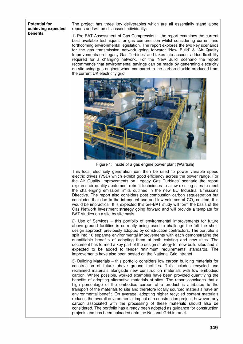
349
Potential for achieving expected benefits
The project has three key deliverables which are all essentially stand alone reports and will be discussed individually:
1) Pre-BAT Assessment of Gas Compression – the report examines the current best available techniques for gas compression whilst considering current and forthcoming environmental legislation. The report explores the two key scenarios for the gas transmission network going forward: ‘New Build’ & ‘Air Quality Improvements on Legacy Gas Turbines’ and takes into account added flexibility required for a changing network. For the ‘New Build’ scenario the report recommends that environmental savings can be made by generating electricity on site using gas engines when compared to the carbon dioxide produced from the current UK electricity grid.
Figure 1: Inside of a gas engine power plant (Wärtsilä)
This local electricity generation can then be used to power variable speed electric drives (VSD) which exhibit good efficiency across the power range. For the Air Quality Improvements on Legacy Gas Turbines’ scenario the report explores air quality abatement retrofit techniques to allow existing sites to meet the challenging emission limits outlined in the new EU Industrial Emissions Directive. The report also considers post combustion carbon sequestration but concludes that due to the infrequent use and low volumes of CO2 emitted, this would be impractical. It is expected this pre-BAT study will form the basis of the Gas Network Investment strategy going forward and will provide a template for BAT studies on a site by site basis.
2) Use of Services – this portfolio of environmental improvements for future above ground facilities is currently being used to challenge the ‘off the shelf’ design approach previously adopted by construction contractors. The portfolio is split into 16 separate environmental improvements with each demonstrating the quantifiable benefits of adopting them at both existing and new sites. The document has formed a key part of the design strategy for new build sites and is expected to be added to tender ‘minimum requirements’ standards. The improvements have also been posted on the National Grid intranet.
3) Building Materials – this portfolio considers low carbon building materials for construction of future above ground facilities. This includes recycled and reclaimed materials alongside new construction materials with low embodied carbon. Where possible, worked examples have been provided quantifying the benefits of adopting alternative materials at sites. The report concludes that a high percentage of the embodied carbon of a product is attributed to the transport of the materials to site and therefore locally sourced materials have an environmental benefit. On average, adopting higher recycled content materials reduces the overall environmental impact of a construction project, however, any carbon associated with the processing of these materials should also be considered. The portfolio has already been adopted as guidance for construction projects and has been uploaded onto the National Grid intranet.
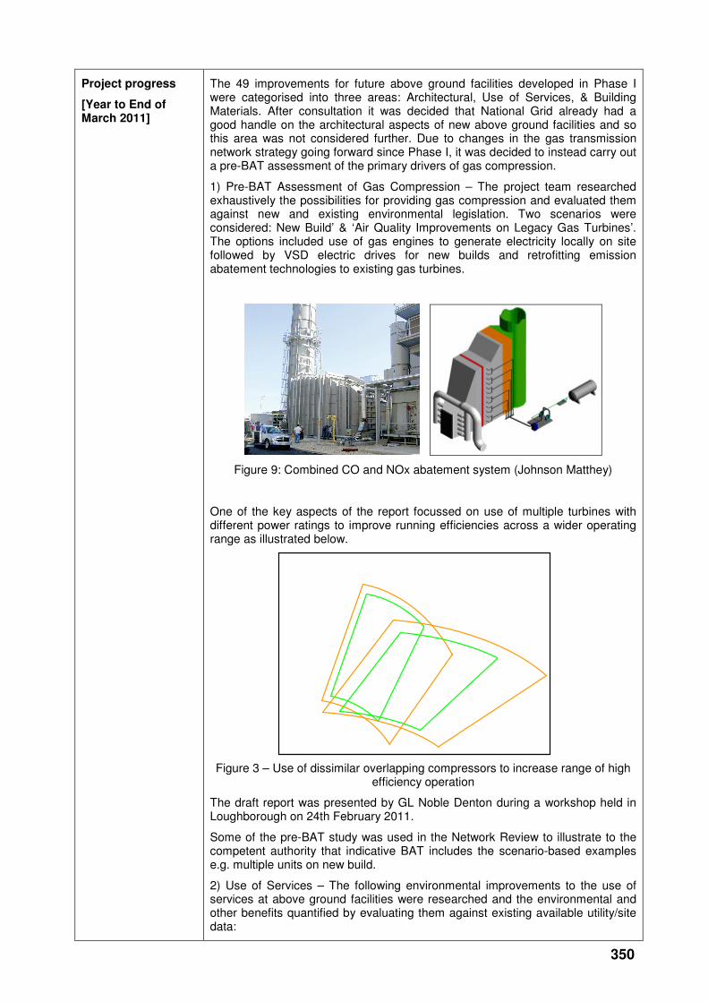
350
Project progress
[Year to End of March 2011]
The 49 improvements for future above ground facilities developed in Phase I were categorised into three areas: Architectural, Use of Services, & Building Materials. After consultation it was decided that National Grid already had a good handle on the architectural aspects of new above ground facilities and so this area was not considered further. Due to changes in the gas transmission network strategy going forward since Phase I, it was decided to instead carry out a pre-BAT assessment of the primary drivers of gas compression.
1) Pre-BAT Assessment of Gas Compression – The project team researched exhaustively the possibilities for providing gas compression and evaluated them against new and existing environmental legislation. Two scenarios were considered: New Build’ & ‘Air Quality Improvements on Legacy Gas Turbines’. The options included use of gas engines to generate electricity locally on site followed by VSD electric drives for new builds and retrofitting emission abatement technologies to existing gas turbines.
Figure 9: Combined CO and NOx abatement system (Johnson Matthey)
One of the key aspects of the report focussed on use of multiple turbines with different power ratings to improve running efficiencies across a wider operating range as illustrated below.
Figure 3 – Use of dissimilar overlapping compressors to increase range of high efficiency operation
The draft report was presented by GL Noble Denton during a workshop held in Loughborough on 24th February 2011.
Some of the pre-BAT study was used in the Network Review to illustrate to the competent authority that indicative BAT includes the scenario-based examples e.g. multiple units on new build.
2) Use of Services – The following environmental improvements to the use of services at above ground facilities were researched and the environmental and other benefits quantified by evaluating them against existing available utility/site data:
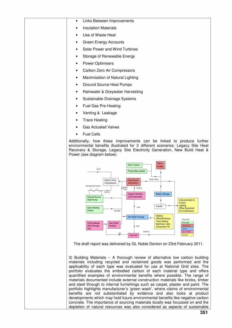
351
• Links Between Improvements
• Insulation Materials
• Use of Waste Heat
• Green Energy Accounts
• Solar Power and Wind Turbines
• Storage of Renewable Energy
• Power Optimisers
• Carbon Zero Air Compressors
• Maximisation of Natural Lighting
• Ground Source Heat Pumps
• Rainwater & Greywater Harvesting
• Sustainable Drainage Systems
• Fuel Gas Pre-Heating
• Venting & Leakage
• Trace Heating
• Gas Actuated Valves
• Fuel Cells
Additionally, how these improvements can be linked to produce further environmental benefits illustrated for 3 different scenarios: Legacy Site Heat Recovery & Storage, Legacy Site Electricity Generation, New Build Heat & Power (see diagram below):
Wind Turbine
Photovoltaic panels
Mains Supply
Gas Engine Generators
Electric Drive Compressors
Organic Rankine Cycle Generator Ground Source
Heat Pump
Solar Heating Panels
Vent/Leakage ANG Storage Gas
Gas Water Heating
Fuel Cell
Hot Water Storage
Battery Storage
Inverter
Heating: Office/Workshop Trace Heating Machinery Cabs Compressor Oil
Instrumentation & Control Lighting Office Equipment Air Compressors
Gas In
Discharge Gas Cooling
Electric Power
Exhaust Electric Power
Gas Out
Hot Water
Heat
Gas Electricity Use of Waste
Storage
Renewable
Fossil Fuels
End Use
Heat
Colour Key
The draft report was delivered by GL Noble Denton on 23rd February 2011.
3) Building Materials – A thorough review of alternative low carbon building materials including recycled and reclaimed goods was performed and the applicability of each type was evaluated for use at National Grid sites. The portfolio evaluates the embodied carbon of each material type and offers quantified examples of environmental benefits where possible. The range of materials documented include external construction materials like bricks, timber and steel through to internal furnishings such as carpet, plaster and paint. The portfolio highlights manufacturer’s ‘green wash’, where claims of environmental benefits are not substantiated by evidence and also looks at product developments which may hold future environmental benefits like negative carbon concrete. The importance of sourcing materials locally was focussed on and the depletion of natural resources was also considered as aspects of sustainable

352
construction techniques.
The draft portfolio was delivered by GL Noble Denton on 9th February 2011.
Collaborative partners
None
R&D provider GL Noble Denton
353
Above Ground Installation Maintenance
Project title AGI Paint Systems
Project Engineer Peter Martin
Description of project
Development of new painting practices for the National Grid gas transmission system’s above ground installations (AGIs) to minimise the costs of future maintenance painting activities.
Expenditure for financial year
Internal £5k
External £25k
Total £30k
Expenditure in previous (IFI) financial years
Internal £8k
External £111k
Total £118k
Total project costs
(collaborative + external + NG)
£222k
Projected 2011/12 costs for NG
£74k
Technological area and/or issue addressed by project
Over the past 10 - 15 years the good condition of the gas transmission asset has allowed National Grid to achieve short-term OPEX savings by considerably reducing the level of corrosion control investment. Due to its age and the reduced level of corrosion investment, the general condition of the asset is now reaching the stage where a reactive approach to corrosion management will no longer be cost effective. Unless action is taken to improve the corrosion management of these assets, there will be a significant increase in repair/replacement costs and the potential for corrosion related failures.
This project will facilitate the development of National Grid’s painting policy and practice for its above ground installations to minimise the cost of maintenance painting.
This objective will be achieved by two developments:
1. Identification of single coat paint systems that can be used to perform local patch repair on existing paint coatings without the requirement for grit-blasting and will provide temporary protection until the next scheduled maintenance painting programme.
2. Identification of over-coating paint systems which can be applied to entire sites to extend the life of the existing coating. This will mitigate having to grit-blast pipe work and structures back to bare metal and re-apply a complete paint system.
Project Benefits Rating
Project Residual Risk
Overall Project Score
Type(s) of innovation involved
Tech Transfer
13 2 11
Expected benefits of project
Failure to invest appropriately in corrosion management of assets is a false economy.
In addition to ensuring the integrity of equipment, a pro-active approach to corrosion management has major financial benefits through:
• Reduced un-scheduled pressure reductions and outages due to corrosion related repairs
• Reduced repair costs
• Maximisation of asset life
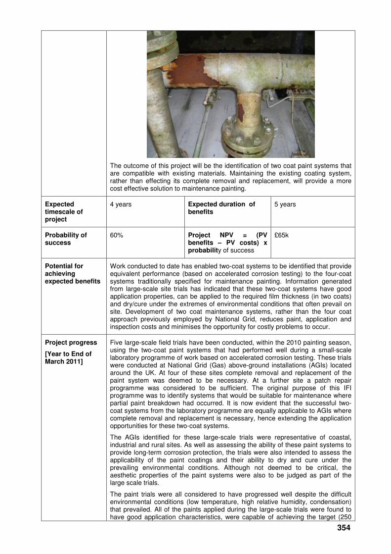
354
The outcome of this project will be the identification of two coat paint systems that are compatible with existing materials. Maintaining the existing coating system, rather than effecting its complete removal and replacement, will provide a more cost effective solution to maintenance painting.
Expected timescale of project
4 years Expected duration of benefits
5 years
Probability of success
60% Project NPV = (PV benefits – PV costs) x probability of success
£65k
Potential for achieving expected benefits
Work conducted to date has enabled two-coat systems to be identified that provide equivalent performance (based on accelerated corrosion testing) to the four-coat systems traditionally specified for maintenance painting. Information generated from large-scale site trials has indicated that these two-coat systems have good application properties, can be applied to the required film thickness (in two coats) and dry/cure under the extremes of environmental conditions that often prevail on site. Development of two coat maintenance systems, rather than the four coat approach previously employed by National Grid, reduces paint, application and inspection costs and minimises the opportunity for costly problems to occur.
Project progress
[Year to End of March 2011]
Five large-scale field trials have been conducted, within the 2010 painting season, using the two-coat paint systems that had performed well during a small-scale laboratory programme of work based on accelerated corrosion testing. These trials were conducted at National Grid (Gas) above-ground installations (AGIs) located around the UK. At four of these sites complete removal and replacement of the paint system was deemed to be necessary. At a further site a patch repair programme was considered to be sufficient. The original purpose of this IFI programme was to identify systems that would be suitable for maintenance where partial paint breakdown had occurred. It is now evident that the successful two-coat systems from the laboratory programme are equally applicable to AGIs where complete removal and replacement is necessary, hence extending the application opportunities for these two-coat systems.
The AGIs identified for these large-scale trials were representative of coastal, industrial and rural sites. As well as assessing the ability of these paint systems to provide long-term corrosion protection, the trials were also intended to assess the applicability of the paint coatings and their ability to dry and cure under the prevailing environmental conditions. Although not deemed to be critical, the aesthetic properties of the paint systems were also to be judged as part of the large scale trials.
The paint trials were all considered to have progressed well despite the difficult environmental conditions (low temperature, high relative humidity, condensation) that prevailed. All of the paints applied during the large-scale trials were found to have good application characteristics, were capable of achieving the target (250
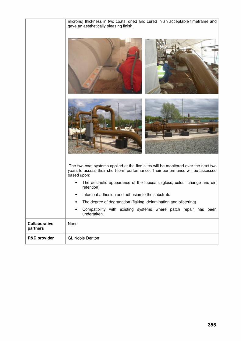
355
microns) thickness in two coats, dried and cured in an acceptable timeframe and gave an aesthetically pleasing finish.
The two-coat systems applied at the five sites will be monitored over the next two years to assess their short-term performance. Their performance will be assessed based upon:
• The aesthetic appearance of the topcoats (gloss, colour change and dirt retention)
• Intercoat adhesion and adhesion to the substrate
• The degree of degradation (flaking, delamination and blistering)
• Compatibility with existing systems where patch repair has been undertaken.
Collaborative partners
None
R&D provider GL Noble Denton
356
Project title Pit Wall Transitions Inspection Technologies
Project Engineer Wayne Lawson
Description of project
Carry out a full market place investigation of available techniques for identifying corrosion within Pit wall transitions (PWTs). This work will involve a full and detailed report on findings together with a presentation to include recommendations of the best available techniques to National Grid which are worthy of further investigation. Once these findings are presented a test rig is to be constructed and the selected techniques assessed further in a simulated environment at PMC Ambergate. Upon successful completion this will go on to a field trial assessment at a selected installation on the NTS. This work will form part of a larger scheme (Stage 2) which will require additional sanction at a later date. The primary aim of the project is to identify an appropriate reliable inspection technique. Previously tested technology has not proved reliable in an operational environment.
However, technology has developed and it now anticipated there may now be an appropriate suitable technique which will allow one of these techniques to be used successfully to determine which pit wall transitions require removal or replacement (under T/PM/CM/4 Grade 4 or 5). The out come of this paper will form the basis of a wider scheme of works to assess, evaluate and repair all identified PWT faults on the NTS as required.
Expenditure for financial year
Internal £5k
External £12k
Total £17k
Expenditure in previous (IFI) financial years
Internal £0
External £0
Total £0
Total project costs (collaborative + external + [company])
£26k Projected [next year] costs for [company]
£9k
Technological area and/or issue addressed by project
The current approved non-invasive inspection techniques (long range ultrasonic technology (LRUT)) have not proven to be reliable in quantifying the metal loss due to corrosion on hidden pipe work running through pit wall transitions on above ground facilities. Due to the unreliability of this technique options are limited to removal of the pit wall or transition regardless of actual need without any substantiated evidence.T/PM/CM/4 requires the following remedial action by visual grade:
• Grade 4: Perform guided wave inspection and assess results.
• Grade 5: Perform guided wave inspection and assess results. Consider removal/replacement of pit wall transition.
• Grade 6: Guided wave inspection has shown indication of corrosion damage. Remove and replace pit wall transition and repair pipeline as appropriate.
“Guided wave inspection” is a generic term for the technologies that will be assessed by this project, it is now hoped that the experience built up by a number of competing techniques with various refinements around the world may now allow one of these techniques to be used successfully to determine which Grade 4 or 5 pit wall transitions require removal or replacement.
Project Benefits Rating
Project Residual Risk
Overall Project Score
Type(s) of innovation involved
Significant
10 -2 12
357
Expected benefits of project
There are currently a number of Terminals/Compressor stations having identified issues of this nature and have registered them on Plant status register. This equates to a significant number of PWT’s (approximately 50 – 60) features which need further investigation.
If an effective suitable technique is established it will be possible to test and assess PWT without the need for excavation. The only alternative is to continue to excavate all pit wall transitions based on their score in plant status (approx 50 - 60). Any excavation works undertaken will require pressure reduction, outages and other flow constraints on the NTS. In addition, historical information has shown for this type of works £125 - 135k per transition is a realistic cost.
Utilising the approved technique will not only give greater confidence in establishing the condition and integrity of the pipe work within the PWT but also when calculating the business costs based on being able to identify a certain percentage of PWT’s that can be kept in their current state for a further extended period of time where they would otherwise need to be repaired as soon as possible.
Expected timescale of project
2 year Duration of benefit once achieved
5 years
Probability of success
60% Project NPV = (PV benefits – PV costs) x probability of success
£241k
Potential for achieving expected benefits
The project has achieved its first objective of identifying a short-list of inspection techniques where there is a reasonable expectation of performance. Subsequent tests on these techniques will now set out to identify their limitations. The information gathered on performance and costs can then be used to formulate a long term investment plan for the repair of PWT’s on the NTS.
Project progress
[Year to End of March 2011]
A full evaluation (and report) has been undertaken by ABB of suitable techniques that are available to National grid in the current marketplace.
Three inspection systems have been short-listed. Wavemaker G3 and MsSR3030R are two variants of the guided wave ultrasonics technology, while AXUS is a longitudinal electromagnetic acoustic transducer system.
Recommendations have been made for the test facility at Ambergate. The test rig is to evaluate the above short-listed techniques for detecting pit wall transition defects, such as corrosion, pitting, mechanical defects and damage associated with the weld. The test rig needs to be representative of typical; constructions, configurations and operating environments. The test rig must also be designed to ensure that limitations of the inspection techniques are highlighted during the tests.
R&D provider ABB (Wilton)
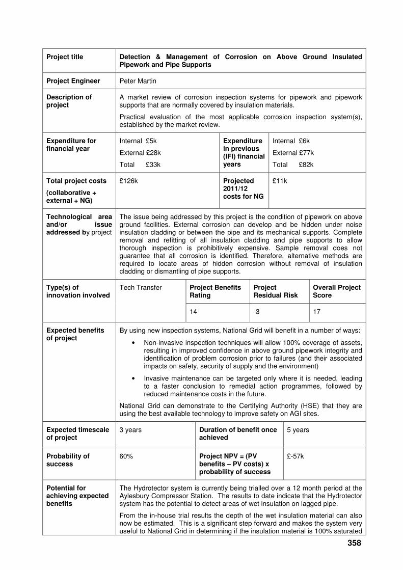
358
Project title Detection & Management of Corrosion on Above Ground Insulated Pipework and Pipe Supports
Project Engineer Peter Martin
Description of project
A market review of corrosion inspection systems for pipework and pipework supports that are normally covered by insulation materials.
Practical evaluation of the most applicable corrosion inspection system(s), established by the market review.
Expenditure for financial year
Internal £5k
External £28k
Total £33k
Expenditure in previous (IFI) financial years
Internal £6k
External £77k
Total £82k
Total project costs
(collaborative + external + NG)
£126k Projected 2011/12 costs for NG
£11k
Technological area and/or issue addressed by project
The issue being addressed by this project is the condition of pipework on above ground facilities. External corrosion can develop and be hidden under noise insulation cladding or between the pipe and its mechanical supports. Complete removal and refitting of all insulation cladding and pipe supports to allow thorough inspection is prohibitively expensive. Sample removal does not guarantee that all corrosion is identified. Therefore, alternative methods are required to locate areas of hidden corrosion without removal of insulation cladding or dismantling of pipe supports.
Project Benefits Rating
Project Residual Risk
Overall Project Score
Type(s) of innovation involved
Tech Transfer
14 -3 17
Expected benefits of project
By using new inspection systems, National Grid will benefit in a number of ways:
• Non-invasive inspection techniques will allow 100% coverage of assets, resulting in improved confidence in above ground pipework integrity and identification of problem corrosion prior to failures (and their associated impacts on safety, security of supply and the environment)
• Invasive maintenance can be targeted only where it is needed, leading to a faster conclusion to remedial action programmes, followed by reduced maintenance costs in the future.
National Grid can demonstrate to the Certifying Authority (HSE) that they are using the best available technology to improve safety on AGI sites.
Expected timescale of project
3 years Duration of benefit once achieved
5 years
Probability of success
60% Project NPV = (PV benefits – PV costs) x probability of success
£-57k
Potential for achieving expected benefits
The Hydrotector system is currently being trialled over a 12 month period at the Aylesbury Compressor Station. The results to date indicate that the Hydrotector system has the potential to detect areas of wet insulation on lagged pipe.
From the in-house trial results the depth of the wet insulation material can also now be estimated. This is a significant step forward and makes the system very useful to National Grid in determining if the insulation material is 100% saturated
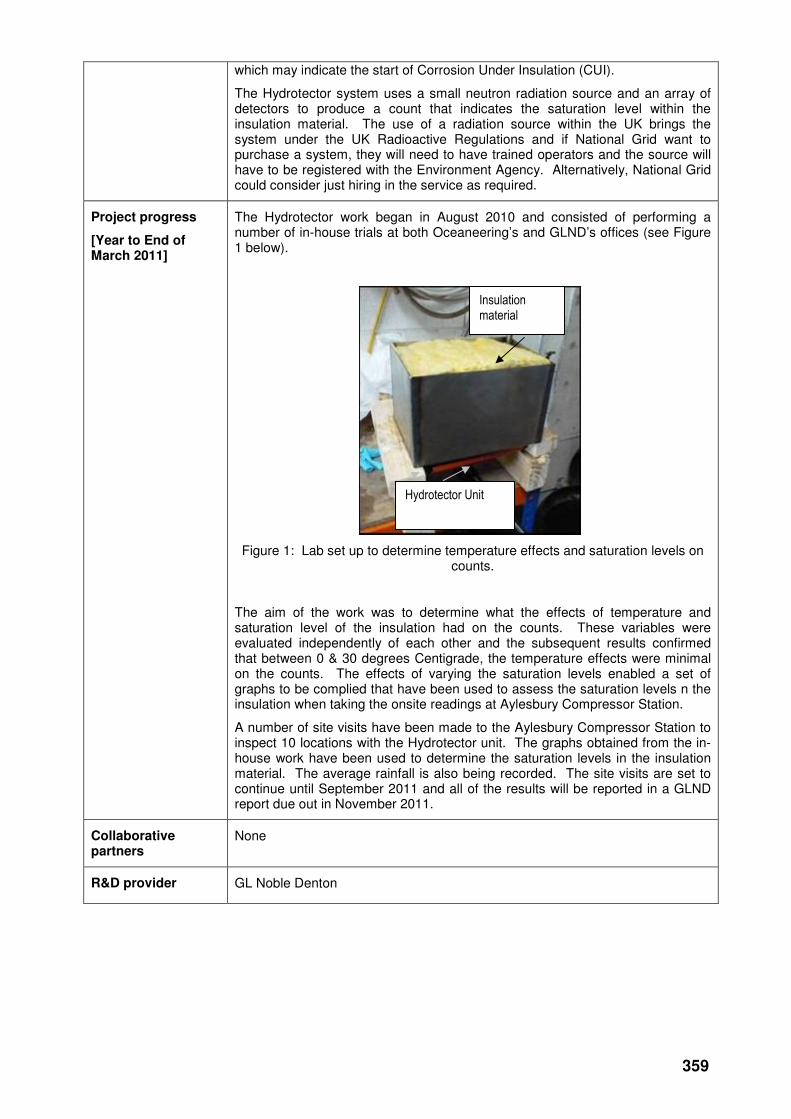
359
which may indicate the start of Corrosion Under Insulation (CUI).
The Hydrotector system uses a small neutron radiation source and an array of detectors to produce a count that indicates the saturation level within the insulation material. The use of a radiation source within the UK brings the system under the UK Radioactive Regulations and if National Grid want to purchase a system, they will need to have trained operators and the source will have to be registered with the Environment Agency. Alternatively, National Grid could consider just hiring in the service as required.
Project progress
[Year to End of March 2011]
The Hydrotector work began in August 2010 and consisted of performing a number of in-house trials at both Oceaneering’s and GLND’s offices (see Figure 1 below).
Figure 1: Lab set up to determine temperature effects and saturation levels on counts.
The aim of the work was to determine what the effects of temperature and saturation level of the insulation had on the counts. These variables were evaluated independently of each other and the subsequent results confirmed that between 0 & 30 degrees Centigrade, the temperature effects were minimal on the counts. The effects of varying the saturation levels enabled a set of graphs to be complied that have been used to assess the saturation levels n the insulation when taking the onsite readings at Aylesbury Compressor Station.
A number of site visits have been made to the Aylesbury Compressor Station to inspect 10 locations with the Hydrotector unit. The graphs obtained from the in-house work have been used to determine the saturation levels in the insulation material. The average rainfall is also being recorded. The site visits are set to continue until September 2011 and all of the results will be reported in a GLND report due out in November 2011.
Collaborative partners
None
R&D provider GL Noble Denton
Insulation material
Hydrotector Unit
360
Metering
Meter assets management
Project title Development of FWACV Capability for New Gas Chromatograph DANINT Software
Project Engineer John Harris / Roger Wood
Description of project
Research, develop and trial the application of more accurate and reliable management of gas composition, calorific value (CV) and volume data at Ofgem-directed sites to enhance the performance of the network.
Implement Flow Weighted Average CV (FWACV) onto improved and next generation gas chromatographs via engineering software that complies with Ofgem’s regulatory requirement, 'The Gas Calculation of Thermal Energy Regulations'.
Expenditure for financial year
Internal £5k
External £16k
Total £21k
Expenditure in previous (IFI) financial years
Internal £0
External £0
Total £0
Total project costs (collaborative + external + NG)
£95k Projected 2011/12 costs for NG
£4k
Technological area and/or issue addressed by project
This project provides an opportunity to improve the accuracy and reliability of data provision from these sites in line with regulatory requirements.
Currently, NGG Transmission and the other four operators are operating Daniels Model 500 Process Gas Chromatographs on Ofgem-directed sites.
The project will research, develop and seek Ofgem approval of a methodology to be delivered in the next release of DANINT software, build 12c, that can interface with next generation (model 700) Daniels Process Gas Chromatographs and also for use with the Model 500 + New Processor card. (Note that NGGT are currently using build 12a software, so additional £5.6k is required to first upgrade to build 12b software)
The broad project aims are to:
• Develop a system solution through information gathering with the supplier of the Ofgem approved analyser
• Develop processes to collect data from the Approved CV analyser and flow computer that can be incorporated into DANINT software.
• Develop the methodology for creation of secure data files that will be used in the calculation of FWACV.
• Support the application to Ofgem for the approval of the software changes, following trials on FWACV system.
Project Benefits Rating
Project Residual Risk
Overall Project Score
Type(s) of innovation involved
Incremental
16 4 12
Expected benefits of project
This project provides an opportunity to enhance network performance through improving the accuracy and reliability of data provision, in line with regulatory requirements. Environmental benefits are also achieved through the reduction in transport associated with site visits and the reduced use of bottled helium gas.
If the improvements are successful, there is also an opportunity to reduce

361
operational costs, as the improved system is rolled out onto NGG Transmission’s FWACV sites.
A typical FWACV site consumes bottled helium gas and requires a bottle change approximately once every 8 weeks. This is a one-day job requiring two members of staff on site. A typical visit costs £545 (£500 in labour and £45 for 1 bottle of Helium) and each site will require 6 visits or costs of £3,270 per year.
If the project is successful, the number of site visits per year is expected to reduce from 6 to 2, resulting in an annual saving of £2,180 per implementation.
The implementation programme is yet to be finalised for NGG Transmission. However, for the purposes of project justification, we can assume that two sites will be converted per year over the next five years (starting next year).
Expected timescale of project
1 year Duration of benefit once achieved
5 years
Probability of success
60% Project NPV = (PV benefits – PV costs) x probability of success
£12k
Potential for achieving expected benefits
The benefits will be realised providing that the new version/equipment is deployed by each funding party. The main benefits expected from the project to date are an operational efficiency saving per site where deployed and compliance with Ofgem approved equipment.
Project progress
[Year to End of March 2011]
Development and testing of revised Ofgem approved DANINT FWACV software for use with Daniel Model 700 gas chromatograph and 2350 (new card) Controller. This included:
• DANINT modules modified to function with 2350 new card controller.
• DANINT build 12B with multi-stream functionality
• DANINT build 12C for use with a 2350A with the new Emerson Ethernet card. This version has been developed in conjunction with Emersons Ethernet card to allow better communication between different modules.
• Engaged in discussions with Emerson to agree address mappings for DANINT communications.
• Completed DANINT software module enhancements and carry out initial testing and User Acceptance Changes (NGG).
• Siemens Microbox deployed replacing Allen-Bradley.
• Support Ofgem approval of DANINT build 12C, carried out at Emerson Factory.
• Produced release CD for installation by GDN’s.
The other development was the revision to the EOD software. Version 5.3 was developed to use the difference in the “Offtake Cumulative Volume Total” between consecutive DAT file records rather than the “Offtake Inst. Volume Flow Rate” as at present. The output included the demonstrating and testing of these revisions, and presenting the results back to Ofgem for approval.
In addition to the above the new version of DANINT has been installed at NGGD’s Holford site. Some issues have occurred but these are not necessarily associated with DANINT. The software will need to be revised and Ofgem will need to be informed. However, Holford may not flow gas and therefore a live operational site will be required for full testing and Holford will be used to complete the Site Acceptance Testing.
Collaborative partners
Leverage of 5:1 on the IFI costs:
• National Grid Gas Distribution – 20% (Project Lead)
• Northern Gas Networks – 20%

362
• Scotia Gas Networks – 20%
• Wales & West Utilities – 20%
• National Grid Gas Transmission – 20%
R&D provider GL Noble Denton
363
Project title AGI Meter Enhancement and Boiler capacity study
Project Engineer John Wilson & Richard Lingard
Description of project
Pilot demonstration of orifice plate metering installation being upgraded to meet the requirements of ISO5167:2003 and reduce future maintenance costs on a high-pressure NTS offtake.
In addition analysis from 3 boiler systems should be able to determine if corrosion inhibitors are present and active and levels of antifreeze.giving indications if corrosion is evident.
Expenditure for financial year
Internal £7k
External £11k
Total £18k
Expenditure in previous (IFI) financial years
Internal £6k
External £147k
Total £153k
Total project costs (collaborative + external + [company])
£170k Projected [next year] costs for [company]
£0
Technological area and/or issue addressed by project
This project aims to demonstrate that the gas flow metering on high pressure offtakes, which supply Power Stations and large industrial users, can be maintained within required measurement uncertainty limits without significant future maintenance intervention.
The improvements that are being demonstrated will comply with ISO5167:2003 (existing installation was ISO5167:1991), bringing the metering into line with industry best practice.
The improvements will also allow gas quality and key process data, including record of validation and flow configuration, to be retained and interrogated remotely.
Understanding the corrosion that occurs in water bath heaters will enable us to estimate of replacements needed across the NTS in water bath heaters.
Project Benefits Rating
Project Residual Risk
Overall Project Score
Type(s) of innovation involved
Incremental
11 -2 13
Expected benefits of project
The new metering system will achieve the required (contractual) uncertainty with a significantly lower maintenance frequency (reduction of maintenance cost and associated environmental impact of travel to site) and with less potential for effort-consuming disputes over metering accuracy.
On the pilot implementation, the total reduction of effort could be more than 300 days/year (although the average for the 27 sites would be quite a bit lower).
In addition to direct technician call out costs, there could also be reductions in the costs associated with processing data for meter error reconciliations. Each meter error can typically require up to 30 man days effort for data processing and there are around 3 meter errors per year across the 27 high pressure offtake sites.
Having the knowledge of rate of corrosion and compiling a list of obsolete components will enable us to estimate of replacement cost of components and budget cost for boiler replacement over the next 5 years.
Expected timescale of project
Installation completed in May 2010.
Duration of benefit once achieved
12 years (expected life of replacement asset)
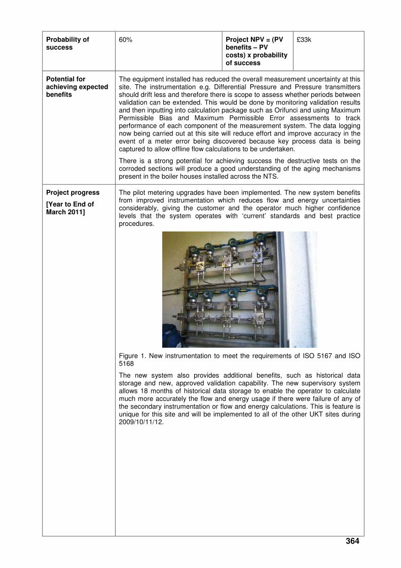
364
Probability of success
60% Project NPV = (PV benefits – PV costs) x probability of success
£33k
Potential for achieving expected benefits
The equipment installed has reduced the overall measurement uncertainty at this site. The instrumentation e.g. Differential Pressure and Pressure transmitters should drift less and therefore there is scope to assess whether periods between validation can be extended. This would be done by monitoring validation results and then inputting into calculation package such as Orifunci and using Maximum Permissible Bias and Maximum Permissible Error assessments to track performance of each component of the measurement system. The data logging now being carried out at this site will reduce effort and improve accuracy in the event of a meter error being discovered because key process data is being captured to allow offline flow calculations to be undertaken.
There is a strong potential for achieving success the destructive tests on the corroded sections will produce a good understanding of the aging mechanisms present in the boiler houses installed across the NTS.
Project progress
[Year to End of March 2011]
The pilot metering upgrades have been implemented. The new system benefits from improved instrumentation which reduces flow and energy uncertainties considerably, giving the customer and the operator much higher confidence levels that the system operates with ‘current’ standards and best practice procedures.
Figure 1. New instrumentation to meet the requirements of ISO 5167 and ISO 5168
The new system also provides additional benefits, such as historical data storage and new, approved validation capability. The new supervisory system allows 18 months of historical data storage to enable the operator to calculate much more accurately the flow and energy usage if there were failure of any of the secondary instrumentation or flow and energy calculations. This is feature is unique for this site and will be implemented to all of the other UKT sites during 2009/10/11/12.
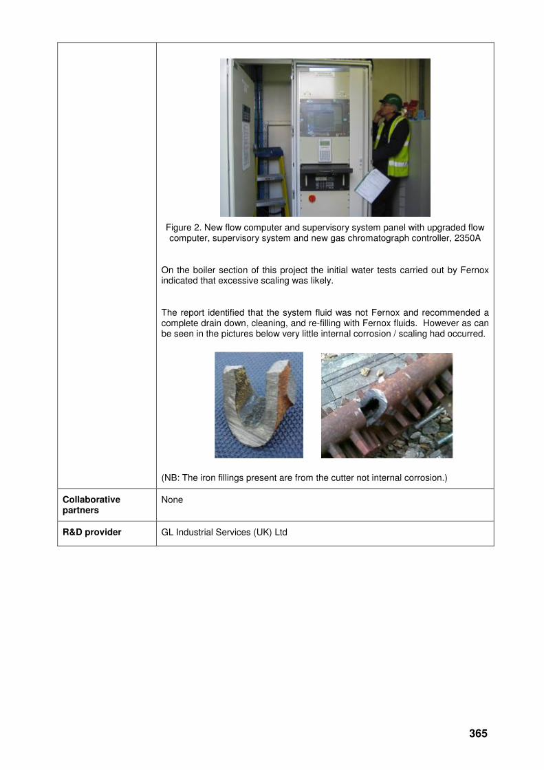
365
Figure 2. New flow computer and supervisory system panel with upgraded flow computer, supervisory system and new gas chromatograph controller, 2350A
On the boiler section of this project the initial water tests carried out by Fernox indicated that excessive scaling was likely.
The report identified that the system fluid was not Fernox and recommended a complete drain down, cleaning, and re-filling with Fernox fluids. However as can be seen in the pictures below very little internal corrosion / scaling had occurred.
(NB: The iron fillings present are from the cutter not internal corrosion.)
Collaborative partners
None
R&D provider GL Industrial Services (UK) Ltd
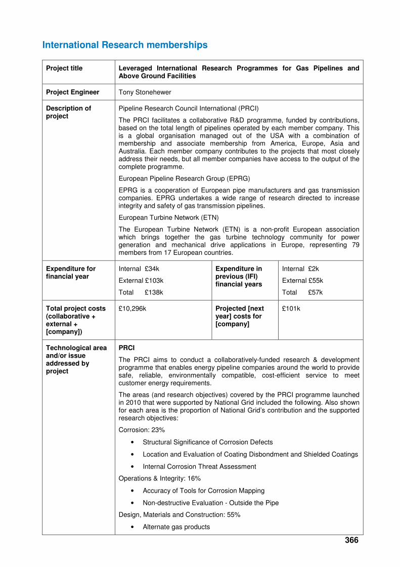
366
International Research memberships
Project title Leveraged International Research Programmes for Gas Pipelines and Above Ground Facilities
Project Engineer Tony Stonehewer
Description of project
Pipeline Research Council International (PRCI)
The PRCI facilitates a collaborative R&D programme, funded by contributions, based on the total length of pipelines operated by each member company. This is a global organisation managed out of the USA with a combination of membership and associate membership from America, Europe, Asia and Australia. Each member company contributes to the projects that most closely address their needs, but all member companies have access to the output of the complete programme.
European Pipeline Research Group (EPRG)
EPRG is a cooperation of European pipe manufacturers and gas transmission companies. EPRG undertakes a wide range of research directed to increase integrity and safety of gas transmission pipelines.
European Turbine Network (ETN)
The European Turbine Network (ETN) is a non-profit European association which brings together the gas turbine technology community for power generation and mechanical drive applications in Europe, representing 79 members from 17 European countries.
Expenditure for financial year
Internal £34k
External £103k
Total £138k
Expenditure in previous (IFI) financial years
Internal £2k
External £55k
Total £57k
Total project costs (collaborative + external + [company])
£10,296k Projected [next year] costs for [company]
£101k
Technological area and/or issue addressed by project
PRCI
The PRCI aims to conduct a collaboratively-funded research & development programme that enables energy pipeline companies around the world to provide safe, reliable, environmentally compatible, cost-efficient service to meet customer energy requirements.
The areas (and research objectives) covered by the PRCI programme launched in 2010 that were supported by National Grid included the following. Also shown for each area is the proportion of National Grid’s contribution and the supported research objectives:
Corrosion: 23%
• Structural Significance of Corrosion Defects
• Location and Evaluation of Coating Disbondment and Shielded Coatings
• Internal Corrosion Threat Assessment
Operations & Integrity: 16%
• Accuracy of Tools for Corrosion Mapping
• Non-destructive Evaluation - Outside the Pipe
Design, Materials and Construction: 55%
• Alternate gas products
367
• Materials & Construction Quality Assurance
• Structural Significance of Mechanical Damage
Measurement: 6%
• Measurement Uncertainty & System Balance and Facility Design
EPRG
The following are the current areas of project activity:
Materials
• (EPRG 137) Assessment of delayed failure under constant pressure
• (EPRG 146) Development of a reliable model for evaluating the ductile fracture propagation resistance for high grade steel pipelines
• (EPRG 148) Investigation of automated ultrasonic testing concept for longitudinally SAW pipe and coupling control
• (EPRG 152) The effect of toughness on the integrity of HFI pipe seam welds
• (EPRG 153) Definition of 'Rich Gas' for ductile crack arrest predictions
• (EPRG 156) Guidelines for mechanised GMAW welding
• (EPRG 157) DWTT for small-diameter thick-walled pipe - seamless
• (EPRG 158) DWTT for small-diameter thick-walled pipe - inverse fracture
• (EPRG 161) CO2 pipelines - shock tube testing
Design
• (EPRG 141) Discrimination for mill features using MLF pigs for baseline inspections- Phase 1
• (EPRG 142) Model of ultimate limit state design to predict combined loading capacity of line pipes
• (EPRG 143) Extension of FFP and puncture resistance criteria to X80
• (EPRG 144) Revision of EPRG guidelines on weld defect acceptance criteria
• (EPRG 145) Assessment of bending wrinkles
• (EPRG 147a) Development of an improved model for the burst strength of dent-gouge damage under sustained internal pressure loading Phase 2 part 1 Modelling
• (EPRG 147b) Development of an improved model for the burst strength of dent-gouge damage under sustained internal pressure loading – Phase 2 part 2 Experimental
• Corrosion
• (EPRG 149) HIC Assessment of low alloy steel line pipe for sour service application Phase 2
• (EPRG 150) HIC Assessment of low alloy steel line pipe for sour service application Phase 3
• (EPRG 151) Assessment of sensitivity to hostile environments of damaged pipe, under cathodic protection and internal pressure
ETN
Cycle Efficiency - Improved performance of gas turbine components and intelligent system integration will enhance fuel efficiency and environmental performance.
Fuel Flexibility & Emissions - Gas turbines capable of operating in an efficient,
368
safe and reliable manner utilising a wide range of fuels whilst minimising polluting emissions such as NOx and aiming at zero CO2 emissions.
Materials Degradation & Repair Technologies - Extend the ultimate life and repair interval for hot section components.
Condition Monitoring, Instrumentation & Control - Aiming for 25,000 hours of gas turbine operation without intervention.
Project Benefits Rating
Project Residual Risk
Overall Project Score
Type(s) of innovation involved
Incremental
21 0 21
Expected benefits of project
PRCI
PRCI’s value proposition: “Formal cost / benefit studies of member participation show a consistently positive ratio of 4:1 to 7:1 from reduced costs of operations and maintenance, inspection, materials, design, construction and testing”.
National Grid Transmission and National Grid Gas Distribution this year used their combined annual contribution of $173k to help launch 14 PRCI projects with a total cost of $3.58m. This represents more than 20:1 average leverage on National Grid supported projects.
EPRG
Improved system integrity knowledge, Improved corrosion protection, reduced 3rd party incidents leading to less supply disruptions. Networking opportunity with other pipeline operators, sharing information and best practice. It is very difficult to articulate the proposed benefits of these high level benefits until the output of each individual project is known.
Significant research leverage benefits of about 15:1, based on an National Grid contribution of €20k.
ETN
ETN promotes environmentally sound Gas Turbine technology with reliable and low cost operation. Besides facilitating and coordinating research effort of different parties, bringing together key stakeholders in the gas turbine community, ETN also presents extensive networking opportunities and acts as solid platform for exchange of knowledge and experiences. ETN identifies research gaps and influences EU research agenda and policy-making at early stage.
Expected timescale of project
Ongoing reviewed annual
Duration of benefit once achieved
Ongoing
Probability of success
70% Project NPV = (PV benefits – PV costs) x probability of success
Ensuring National Grid is kept at the forefront of Gas Research.
Potential for achieving expected benefits
The PRCI collaborative programme gives National Grid the opportunity to benefit from a significant number of highly leveraged projects which compliment much of the work on the overall IFI programme. It also provides a link with PRCI global membership and benefits of identifying emerging threats and opportunities.
The EPRG programme of work has potential for achieving the expected benefits due the collaborative nature of the projects. The R&D leverage ratio of 15:1 and the shared knowledge on best practice and incidents are the main benefits and a consistency between our Distribution and Transmission businesses.
National Grid predominantly uses ETN as a forum to help identify emerging issues and opportunities with gas turbine mechanical drives.
Project progress PRCI
369
[Year to End of March 2011]
The following National Grid supported projects were launched this year by PRCI:
Corrosion:
• Develop Leak/Rupture Boundary for Corrosion in Low Toughness Pipe (Leverage 14)
• Performance of Above Ground Coating Evaluation Survey Method (Leverage 4)
• Integrity Issues for CO2 Pipeline Transport Including Corrosion, Cracking, and Rupture (Leverage 8)
Operations & Integrity:
• ILI Tool Error Calibration Based on In-the-Ditch Measurements with Related Uncertainty (Leverage 31)
• Improved Pipeline Reliability by Using In-Ditch Verification Data to Measure ILI Uncertainty and Applying Correction Factors (Leverage 13)
• Base Resource Document for Unpiggable Pipelines (Leverage 12)
Design, Materials and Construction:
• CO2 Shock Tube Testing (Leverage 6)
• Guidelines to Address Pipe Material and Construction Quality Issues in Response to Current Concerns (Leverage 18)
• Full-Scale Experimental Validation of Mechanical Damage Assessment Models (Leverage 10)
• Full-Scale Demonstration of the Interaction of Dents with Localized Corrosion Defects (Leverage 31)
• Improved Model for Predicting the Burst Pressure of Dent + Gouge Damage (Leverage 20)
• Improved Model for Predicting the Time/Cycle Dependent Behaviour of Dent + Gouge Damage (Leverage 20)
• Assessment of Delayed Failure for Mechanical Damage Under Constant Pressure (Leverage 14)
Measurement:
• Effect of Upstream Piping Configurations on Ultrasonic Meter Bias (Leverage 18)
Reports were delivered by PRCI during the year for the following National Grid supported projects:
Projects Launched in 2007
Extend Solar Turbines DLN Operating Range (Leverage 33)
Projects Launched in 2008
Large-Scale Cathodic Disbondment Testing for CTE (Leverage 52)
Variable CP Criteria (Leverage 24)
Methods to Reduce the Carbon Footprint of Pipeline Stations (Leverage 42)
Projects Launched in 2009
CO2 Transmission and Storage - Research Plan Development (Leverage 7)
EPRG
Three meetings of the EPRG Materials Committee have been attended. The documented procedures that are currently applied to gas transmission and distribution operations in the UK have been reviewed to establish how to incorporate any knowledge gained from the recent EPRG projects delivered.
ETN

370
Key topics of this year’s AGM and Workshop included:
• EU Energy Policy Update
• New ETN Position Paper on the Technological Impact of Power Plant Operation of an Increasing Amount of Renewable Energy in the Grid
• Natural Gas Interchangeability Study
• Outcome of the International Gas Turbine Conference 2010 and Follow-up on the Creativity Session.
Collaborative partners
PRCI is a collaboration with National Grid Gas Distribution (UK) and 34 other companies with energy pipeline interests (23 based in the USA; 5 European; 5 Canadian; 1 South American; 1 Middle-Eastern)
EPRG is a collaboration with National Grid Gas Distribution and 17 other European pipe manufacturers and gas transmission companies
ETN has 78 other members from 17 European countries
R&D provider PRCI (which uses a selection of Research Contractors, including large, multi-discipline corporations, non-profit institutions, small, pipeline niche firms, major colleges and universities).
EPRG (which uses a range of European Research Contractors)
GL Noble Denton
ETN