Embed Size (px)
Citation preview
KIT – University of the State of Baden-Wuerttemberg and
National Research Center of the Helmholtz Association
Institute for Neutron Physics and Reactor Technology
www.kit.edu
Gases, in Particular Helium, as Nuclear Reactor Coolant
E. Bubelis
Institute for Neutron Physics and Reactor Technology
(INR)
2 2013.02.20. E. Bubelis – Seminar "Coolants for fast neutron reactors", Paris
Contents
Gas-cooled reactors. History
Current high-temperature reactors
Gen-IV advanced reactors
EC financed gas-cooled reactor projects
Motivation for gas-cooled fast reactors
Carbon dioxide vs. Helium
Specific motivations for helium usage
Gas coolants. Advantages & Disadvantages
Conclusions
Institute for Neutron Physics and Reactor Technology
(INR)
3 2013.02.20. E. Bubelis – Seminar "Coolants for fast neutron reactors", Paris
Gas-cooled reactors. History (1)
Gases as reactor coolants have been used since the earliest days of
nuclear power ► 1947, Windscale Piles, UK (atmospheric air cooled,
graphite mod., low pres. & temp., open cycle, large pumping power)
First generation gas-cooled power reactors ► 1953, Magnox
reactors, UK (CO2 cooled, pressurized gas, higher temperatures
enough for commercial electricity generation, closed cycle)
Second generation ► 1960s onwards, Advanced gas cooled reactors
– AGRs (CO2 cooled, Tcoolout = 650oC, good quality superheated steam,
high thermal efficiency – 42%)
Many CO2-cooled thermal reactors have been built and many are still
operating ► > 1000 reactor-years of operation experience in UK alone
Institute for Neutron Physics and Reactor Technology
(INR)
4 2013.02.20.
Problem with carbon dioxide that became apparent in AGRs:
At AGR temperatures (~600oC), CO2 dissociates into CO and O2 under the
combined action of heat and radiation (radiolytic dissociation),
The free oxygen oxidizes the graphite and metallic structures,
CO2 dissociation can be mitigated using methane:
CO2 + CH4 → C + 2CO +2H2O,
The carbon gets deposited to “repair” the graphite, the CO builds up to a
equilibrium concentration to limit further dissociation and water vapour is
extracted by the coolant treatment system,
The rate of CO2 dissociation becomes unacceptable at higher temperatures.
Gas-cooled reactors. History (2)
E. Bubelis – Seminar "Coolants for fast neutron reactors", Paris
Institute for Neutron Physics and Reactor Technology
(INR)
5 2013.02.20. E. Bubelis – Seminar "Coolants for fast neutron reactors", Paris
Helium was adopted for high temperature thermal reactors (HTRs) to
avoid the radiolytic dissociation problems associated with carbon
dioxide.
HTRs operated are: Dragon (UK), AVR and THTR-300 (Germany), Peach
Bottom and Fort St Vrain (US), HTR-10 (China), HTTR (Japan)
► significant amount of operating experience of helium-cooled reactors
has been accumulated;
Outlet temperatures of 750oC to 950oC
► allows high-efficiency electricity generation and production of high-
quality process heat.
Gas-cooled reactors. History (3)
Institute for Neutron Physics and Reactor Technology
(INR)
6 2013.02.20. E. Bubelis – Seminar "Coolants for fast neutron reactors", Paris
All power reactors in use today are “thermal” reactors (fission of U-235)
For nuclear fission to be considered sustainable, the utilization of natural
uranium has to be improved considerably ► practical improvement (by a
factor 60): breeding of Pu from U-238 and burning it in a “fast” reactor
“Fast” reactor cores are compact ► require a very effective coolant to
transport heat: liquid metal (sodium, etc.) or an alternative gas coolant
Both carbon dioxide and helium have been proposed as gas-cooled fast
reactor (GCFR) coolants
CO2 dissociation problem is less of an issue in GCFR because there is no
graphite to oxidize, but there are still metallic components in the reactor ...
Gas-cooled reactors. History (4)
Institute for Neutron Physics and Reactor Technology
(INR)
7 2013.02.20. E. Bubelis – Seminar "Coolants for fast neutron reactors", Paris
Commertial-scale helium-cooled HTR projects were pursued in Germany
and the USA
German program ended in the 1990s, but activity continued in the USA
USA-Russia collaboration led to the development of gas turbine modular
high-temperature reactor (GT-MHR) concept: has prismatic fuel element
core; uses direct-cycle helium gas turbine
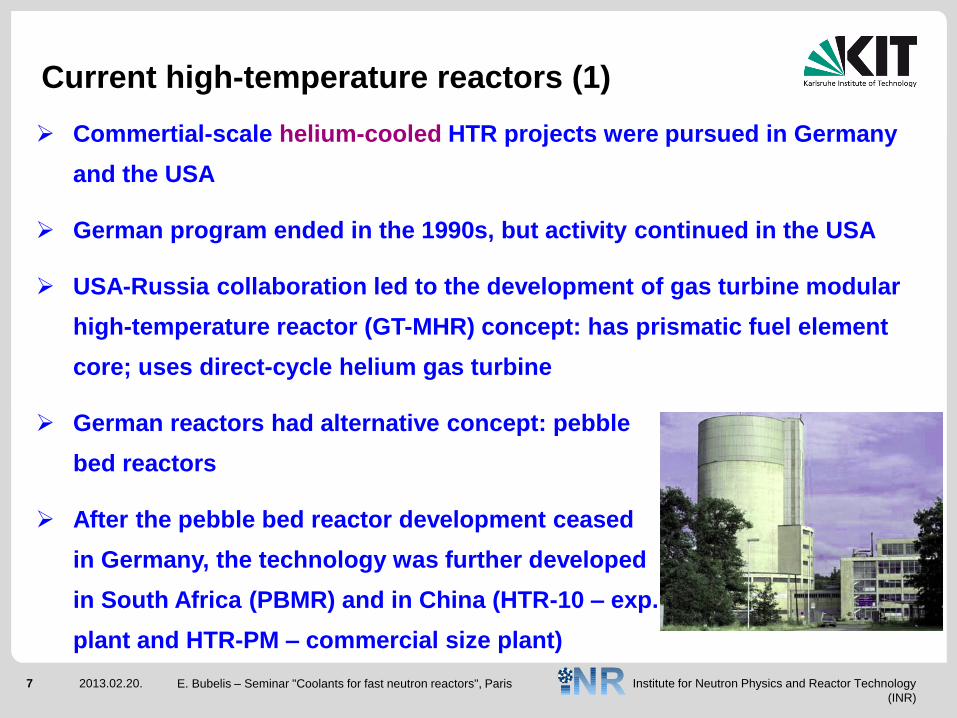
German reactors had alternative concept: pebble
bed reactors
After the pebble bed reactor development ceased
in Germany, the technology was further developed
in South Africa (PBMR) and in China (HTR-10 – exp.
plant and HTR-PM – commercial size plant)
Current high-temperature reactors (1)
Institute for Neutron Physics and Reactor Technology
(INR)
8 2013.02.20. E. Bubelis – Seminar "Coolants for fast neutron reactors", Paris
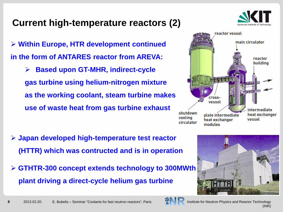
Within Europe, HTR development continued
in the form of ANTARES reactor from AREVA:
Based upon GT-MHR, indirect-cycle
gas turbine using helium-nitrogen mixture
as the working coolant, steam turbine makes
use of waste heat from gas turbine exhaust
Japan developed high-temperature test reactor
(HTTR) which was contructed and is in operation
GTHTR-300 concept extends technology to 300MWth
plant driving a direct-cycle helium gas turbine
Current high-temperature reactors (2)
Institute for Neutron Physics and Reactor Technology
(INR)
9 2013.02.20. E. Bubelis – Seminar "Coolants for fast neutron reactors", Paris
In all above designs the reactor cores are cooled by high-purity helium
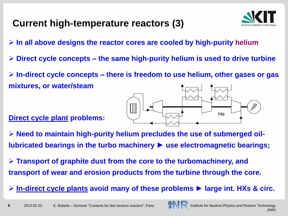
Direct cycle concepts – the same high-purity helium is used to drive turbine
In-direct cycle concepts – there is freedom to use helium, other gases or gas
mixtures, or water/steam
Direct cycle plant problems:
Need to maintain high-purity helium precludes the use of submerged oil-
lubricated bearings in the turbo machinery ► use electromagnetic bearings;
Transport of graphite dust from the core to the turbomachinery, and
transport of wear and erosion products from the turbine through the core.
In-direct cycle plants avoid many of these problems ► large int. HXs & circ.
Current high-temperature reactors (3)
He
Institute for Neutron Physics and Reactor Technology
(INR)
10 2013.02.20. E. Bubelis – Seminar "Coolants for fast neutron reactors", Paris
Gen-IV advanced reactors (1)
Gen-IV initiative launched by USDOE in the early 2000s
Six systems were proposed for further development – 3 are fast reactors, 3
are thermal or epithermal spectrum reactors
One fast reactor (GFR) and one thermal reactor (VHTR) require helium as the
reactor core coolant (primary coolant)
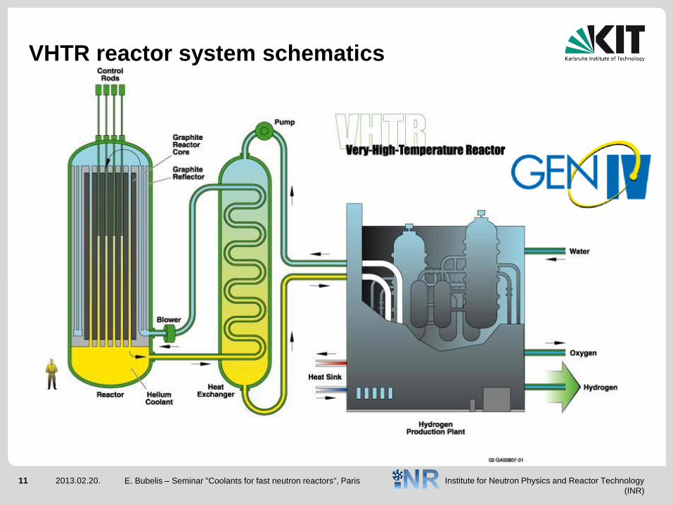
VHTR is an extrapolation from the existing high-temperature reactor
technology, aiming at core outlet temperatures of ~ 1000 oC
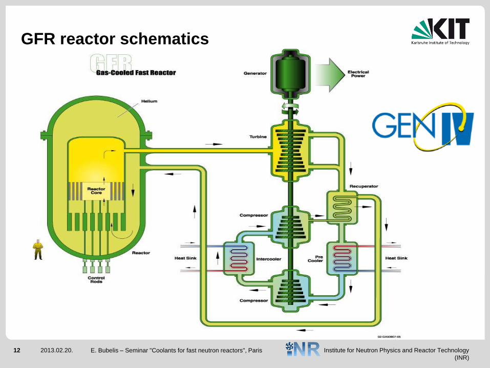
GFR system aims to capitalize on fast-reactor and high-temperature reactor
experience
Institute for Neutron Physics and Reactor Technology
(INR)
11 2013.02.20. E. Bubelis – Seminar "Coolants for fast neutron reactors", Paris
VHTR reactor system schematics
Institute for Neutron Physics and Reactor Technology
(INR)
12 2013.02.20. E. Bubelis – Seminar "Coolants for fast neutron reactors", Paris
GFR reactor schematics
Institute for Neutron Physics and Reactor Technology
(INR)
13 2013.02.20. E. Bubelis – Seminar "Coolants for fast neutron reactors", Paris
Significant advantage of fast reactors in general is their ability to fission the
long-lived radionuclides (MA – neptunium, americium & curium)
GFR is particularly effective owing to the larger proportion of high-energy
neutrons present in its neutron spectum compared with SFR ↔ number of
coolant atoms per unit volume is smaller in a gas-cooled core compared with a
liquid sodium-cooled core (amount of moderation is smaller)
Helium offers the best performance in terms of high-temperature chemical
stability and a high level of nuclear stability
Other gases have advantages in terms of higher density, need of lower
pumping power and better natural convection performance
Gen-IV advanced reactors (2)
Institute for Neutron Physics and Reactor Technology
(INR)
14 2013.02.20. E. Bubelis – Seminar "Coolants for fast neutron reactors", Paris
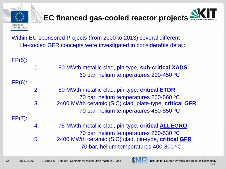
EC financed gas-cooled reactor projects
Within EU-sponsored Projects (from 2000 to 2013) several different
He-cooled GFR concepts were investigated in considerable detail:
FP(5):
1. 80 MWth metallic clad, pin-type, sub-critical XADS
60 bar, helium temperatures 200-450 oC
FP(6):
2. 50 MWth metallic clad, pin-type, critical ETDR
70 bar, helium temperatures 260-560 oC 3. 2400 MWth ceramic (SiC) clad, plate-type, critical GFR
70 bar, helium temperatures 480-850 oC
FP(7):
4. 75 MWth metallic clad, pin-type, critical ALLEGRO
70 bar, helium temperatures 260-530 oC 5. 2400 MWth ceramic (SiC) clad, pin-type, critical GFR
70 bar, helium temperatures 400-800 oC
Institute for Neutron Physics and Reactor Technology
(INR)
15 2013.02.20. E. Bubelis – Seminar "Coolants for fast neutron reactors", Paris
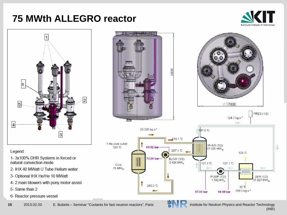
75 MWth ALLEGRO reactor
Institute for Neutron Physics and Reactor Technology
(INR)
16 2013.02.20. E. Bubelis – Seminar "Coolants for fast neutron reactors", Paris
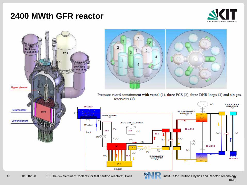
2400 MWth GFR reactor
Institute for Neutron Physics and Reactor Technology
(INR)
17 2013.02.20. E. Bubelis – Seminar "Coolants for fast neutron reactors", Paris
Motivation for gas-cooled fast reactors (1)
Fast reactors are important for the sustainability of nuclear power:
More efficient use of fuel,
Reduced volumes and radiotoxicity of high level waste.
Sodium cooled fast reactors are the shortest route to FR deployment,
but:
Sodium coolant has some undesirable features: chemical
compatibility, positive void coefficient of reactivity, restricted
core outlet temperature to avoid sodium boiling, etc.
Institute for Neutron Physics and Reactor Technology
(INR)
18 2013.02.20. E. Bubelis – Seminar "Coolants for fast neutron reactors", Paris
Gas cooled fast reactors do not suffer from any of the above:
Chemically inert, void coefficient is small (but still positive),
single phase coolant eliminates boiling,
Allows high temperature operation without the corrosion and
coolant radio-toxicity problems associated with heavy liquid
metal reactors (LBE or pure Pb), but …
Gaseous coolants have little thermal inertia ► rapid heat-up of
the core following loss of forced circulation, due to the lack of
thermal inertia of the core structure & very high power density.
Motivation is: enhanced safety, low radio-toxicity and improved reactor
performance.
Motivation for gas-cooled fast reactors (2)
Institute for Neutron Physics and Reactor Technology
(INR)
19 2013.02.20. E. Bubelis – Seminar "Coolants for fast neutron reactors", Paris
Carbon dioxide vs. Helium (1)
Molecular weights: M ~44 kg/kmol for CO2 and ~ 4 kg/kmol for He.
For any working pressure a CO2 cooled core will require less pumping
power than a He cooled core ► He gas at high pressure.
Cp,CO2 = 1.15 kJ/kg/K and Cp,He = 5.195 kJ/kg/K.
He is a superior gas as regards the thermal conductivity.
Gases: “Poor” heat transfer from surface to coolant.
Solution: change Nu and heat transfer area. Nusselt number is changed
by changing the geometry and/or by changing the amount of
turbulence (rib roughened pins, metallic clad). The area is changed by
changing the geometry or by extending the surfaces (fins).
Institute for Neutron Physics and Reactor Technology
(INR)
20 2013.02.20. E. Bubelis – Seminar "Coolants for fast neutron reactors", Paris
Of the two gases, He is chemically inert whereas CO2 can dissociate.
Generally, the damaging mechanism with dissociated CO2 is high
temperature oxidation as opposed to traditional “wet” corrosion
associated with water-cooled systems.
The oxidation rates in CO2-cooled reactors are generally lower
than in water-cooled reactors,
Much experience exist in CO2-cooled thermal reactors on
management and limitation of oxidation.
Carbon dioxide vs. Helium (2)
Institute for Neutron Physics and Reactor Technology
(INR)
21 2013.02.20. E. Bubelis – Seminar "Coolants for fast neutron reactors", Paris
Whilst helium is an inert gas, there is still the possibility of chemical
attack of the structural materials.
With most common structural metals, they are protected by a
thin, self-repairing, oxide layer that forms naturally in an oxygen
containing atmosphere.
In an inert atmosphere, if the oxide layer is damaged, there is no
oxygen available to repair the layer.
Residual grit content in the primary gas (other gases, steam …)
could lead to chemical interactions with internal components ►
Needs continuous purification of the gas.
Carbon dioxide vs. Helium (3)
Institute for Neutron Physics and Reactor Technology
(INR)
22 2013.02.20. E. Bubelis – Seminar "Coolants for fast neutron reactors", Paris
In a helium environment, an associated problem is tribology.
Surfaces which slide against each other, e.g., bearings, valves
and valve seats, and screw threads can effectively weld
themselves together (diffusion bonding).
This occurs through of the exchange of metal atoms, by
diffusion, through the oxide-free surfaces under the action of
contact pressure, heat and time.
This is a particular problem for safety systems, such as
decay heat removal system valves.
Carbon dioxide vs. Helium (4)
Institute for Neutron Physics and Reactor Technology
(INR)
23 2013.02.20. E. Bubelis – Seminar "Coolants for fast neutron reactors", Paris
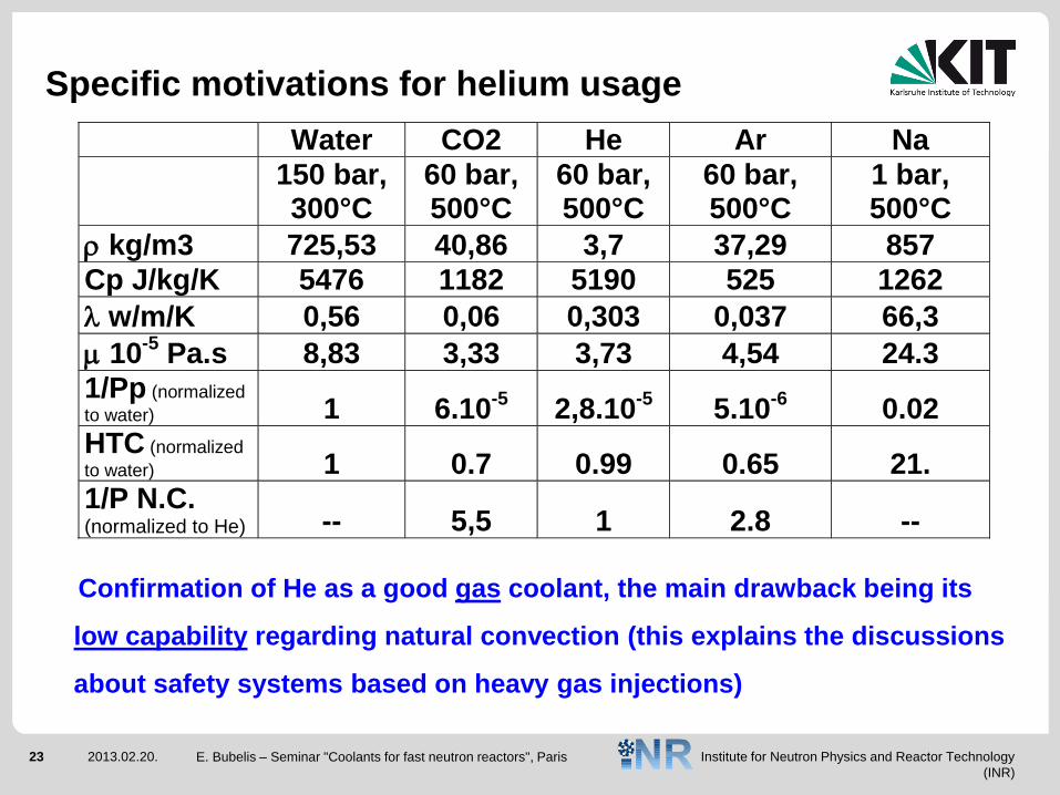
Specific motivations for helium usage
Water CO2 He Ar Na
150 bar, 300°C
60 bar, 500°C
60 bar, 500°C
60 bar, 500°C
1 bar, 500°C
kg/m3 725,53 40,86 3,7 37,29 857
Cp J/kg/K 5476 1182 5190 525 1262
w/m/K 0,56 0,06 0,303 0,037 66,3
10-5
Pa.s 8,83 3,33 3,73 4,54 24.3
1/Pp (normalized
to water) 1 6.10-5
2,8.10-5
5.10-6
0.02
HTC (normalized
to water) 1 0.7 0.99 0.65 21.
1/P N.C. (normalized to He) -- 5,5 1 2.8 --
Confirmation of He as a good gas coolant, the main drawback being its
low capability regarding natural convection (this explains the discussions
about safety systems based on heavy gas injections)
Institute for Neutron Physics and Reactor Technology
(INR)
24 2013.02.20. E. Bubelis – Seminar "Coolants for fast neutron reactors", Paris
Gas coolants. Advantages
The main safety advantages of gas coolants are:
No change in phase of the gas coolant (single phase behaviour);
Low reactivity insertion due to voiding of the coolant;
Optically transparent (simple in-service inspection of the primary
system and internal vessel components) and electrically non-
conducting.
Institute for Neutron Physics and Reactor Technology
(INR)
25 2013.02.20. E. Bubelis – Seminar "Coolants for fast neutron reactors", Paris
Gas coolants. Disadvantages (1)
The main safety disadvantages of gas coolants are:
The low density creating the requirement for pressurization -
increases the likelihood and severity of a LOCA.
Loss of pressure can induce positive reactivity insertions due
to voiding, however the effect is relatively small.
Water/Steam ingress into primary circuit due to HX tube failure
can induce significant positive reactivity insertions in addition
to chemical attacks.
Institute for Neutron Physics and Reactor Technology
(INR)
26 2013.02.20. E. Bubelis – Seminar "Coolants for fast neutron reactors", Paris
Gas coolants. Disadvantages (2)
The inability to form a pool, a problem when trying to ensure that the
reactor core remains bathed in coolant within a breached primary
cooling circuit;
Following a severe accident it is easier to manage the core
debris if immersed in a pool of liquid coolant, both in terms of
cooling and restriction of the release of the fission products into
the containment building.
Institute for Neutron Physics and Reactor Technology
(INR)
27 2013.02.20. E. Bubelis – Seminar "Coolants for fast neutron reactors", Paris
Gas coolants. Disadvantages (3)
The non-condensable nature of coolant, if it is lost from the reactor
cooling circuit - a problem for pressure loading of the containment.
Low thermal inertia means that the reactor core will heat up rapidly
if forced cooling or high coolant pressure is lost.
The low thermal inertia of the coolant is of particular significance in
a fast reactor core.
The core itself possesses little thermal inertia, so the fuel
temperatures rise rapidly following a loss of forced circulation of
the coolant or the loss of the high coolant pressure.
Institute for Neutron Physics and Reactor Technology
(INR)
28 2013.02.20. E. Bubelis – Seminar "Coolants for fast neutron reactors", Paris
Gas coolants. Disadvantages (4)
The compact core makes the “conduction cool-down” heat path
insufficient to remove the decay heat, thus remaining within the
fuel temperature limits.
Convective cooling is required, either by restoration of forced
cooling (through a back-up cooling system or a dedicated forced
convection decay heat removal system), or by natural convection
(supported by the heavy gas (nitrogen) injection).
However, natural convection of gas is not efficient at low
pressures due to the low gas density, especially for Helium.
Institute for Neutron Physics and Reactor Technology
(INR)
29 2013.02.20.
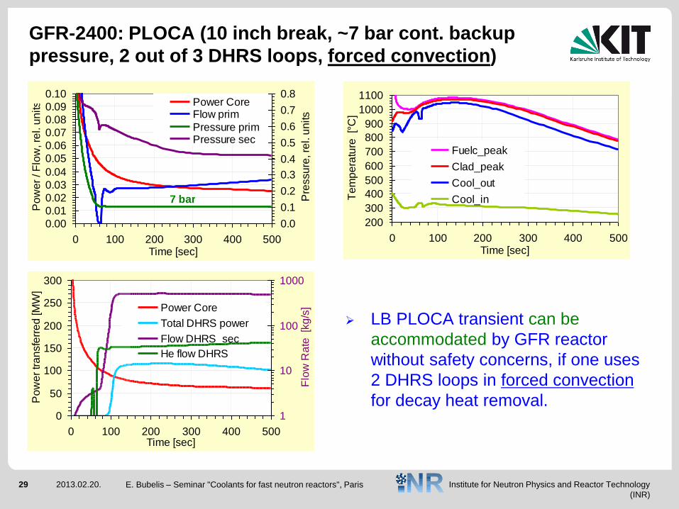
GFR-2400: PLOCA (10 inch break, ~7 bar cont. backup
pressure, 2 out of 3 DHRS loops, forced convection)
LB PLOCA transient can be
accommodated by GFR reactor
without safety concerns, if one uses
2 DHRS loops in forced convection
for decay heat removal.
0.00
0.01
0.02
0.03
0.04
0.05
0.06
0.07
0.08
0.09
0.10
0 100 200 300 400 500Time [sec]
Po
we
r / F
low
, re
l. u
nits
0.0
0.1
0.2
0.3
0.4
0.5
0.6
0.7
0.8
Pre
ssu
re, re
l. u
nits
Power CoreFlow prim
Pressure primPressure sec
7 bar
200
300
400
500
600
700
800
900
1000
1100
0 100 200 300 400 500Time [sec]
Te
mp
era
ture
[°
C]
Fuelc_peak
Clad_peak
Cool_out
Cool_in
0
50
100
150
200
250
300
0 100 200 300 400 500Time [sec]
Po
we
r tr
an
sfe
rre
d [M
W]
1
10
100
1000
Flo
w R
ate
[k
g/s
]Power Core
Total DHRS power
Flow DHRS_sec
He flow DHRS
E. Bubelis – Seminar "Coolants for fast neutron reactors", Paris
Institute for Neutron Physics and Reactor Technology
(INR)
30 2013.02.20.
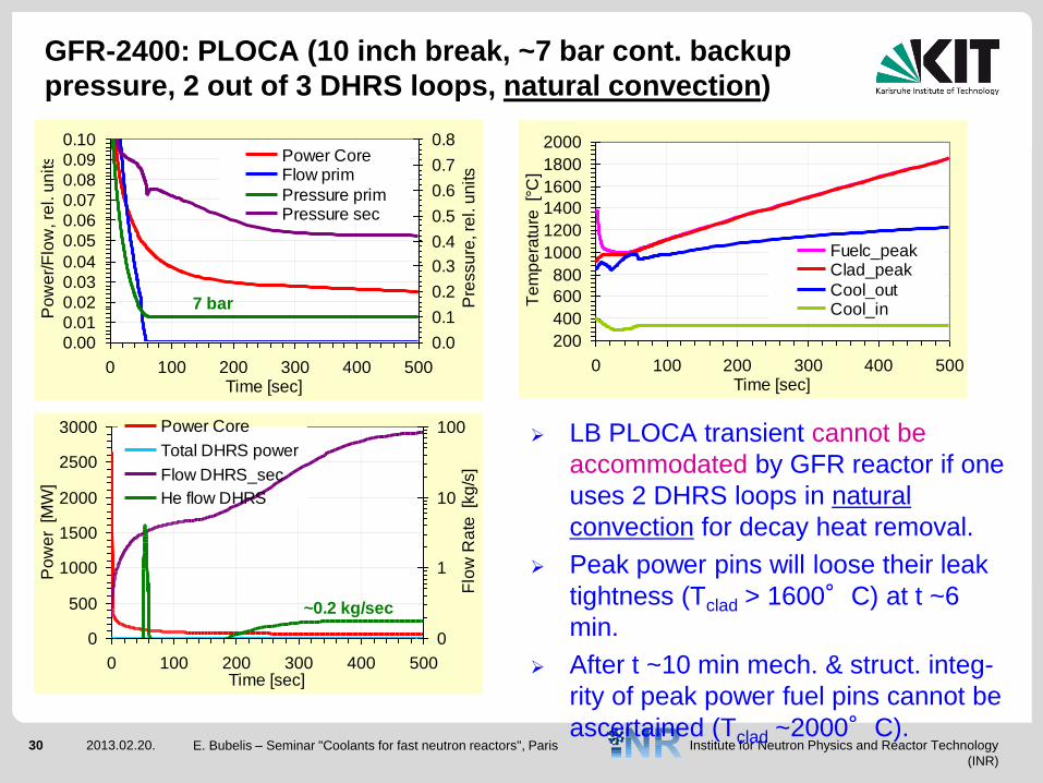
GFR-2400: PLOCA (10 inch break, ~7 bar cont. backup
pressure, 2 out of 3 DHRS loops, natural convection)
LB PLOCA transient cannot be
accommodated by GFR reactor if one
uses 2 DHRS loops in natural
convection for decay heat removal.
Peak power pins will loose their leak
tightness (Tclad > 1600°C) at t ~6
min.
After t ~10 min mech. & struct. integ-
rity of peak power fuel pins cannot be
ascertained (Tclad ~2000°C).
0.00
0.01
0.02
0.03
0.04
0.05
0.06
0.07
0.08
0.09
0.10
0 100 200 300 400 500Time [sec]
Po
we
r/F
low
, re
l. u
nits
0.0
0.1
0.2
0.3
0.4
0.5
0.6
0.7
0.8
Pre
ssu
re, re
l. u
nits
Power CoreFlow prim
Pressure primPressure sec
7 bar
200
400
600
800
1000
1200
1400
1600
1800
2000
0 100 200 300 400 500Time [sec]
Te
mp
era
ture
[°
C]
Fuelc_peakClad_peak
Cool_outCool_in
0
500
1000
1500
2000
2500
3000
0 100 200 300 400 500Time [sec]
Po
we
r [M
W]
0
1
10
100
Flo
w R
ate
[k
g/s
]
Power Core
Total DHRS power
Flow DHRS_sec
He flow DHRS
~0.2 kg/sec
E. Bubelis – Seminar "Coolants for fast neutron reactors", Paris
Institute for Neutron Physics and Reactor Technology
(INR)
31 2013.02.20. E. Bubelis – Seminar "Coolants for fast neutron reactors", Paris
Conclusions
Gas-cooled reactors have been deployed on an industrial scale for over
half a century, thus accumulating huge operational experience.
However, most of these reactors are CO2-cooled thermal reactors with
moderate operating temperatures.
Helium fits the requirement for high operating temperatures well and is
the coolant of choice for high-temperature thermal reactors (HTRs).
Chemical and nuclear stability of helium makes it a good candidate also
for gas-cooled fast reactors.
VHTR and GFR are the two Gen-IV systems in which helium has been
chosen as the reference gaseous coolant.
Institute for Neutron Physics and Reactor Technology
(INR)
32 2013.02.20. E. Bubelis – Seminar "Coolants for fast neutron reactors", Paris
References
1. The future of helium as a natural resource, edited by W. J. Nuttall, R. H. Clarke
and B. A. Glowacki, Routledge, London, NY, 2012.
2. Basis for the Safety Approach for Design & Assessment of Generation IV Nuclear
Systems, Rev. I, prepared by RSWG of Gen-IV IF, OECD NEA, November 2008.
3. Á. Horváth and R. Stainsby “ALLEGRO – a Gas‐Cooled Fast Reactor
Demonstrator. Status of the Project”, GoFastR project presentation, 2012.
4. C. Poette “Gas cooled fast reactor. System design”, GoFastR project workshop,
Cadarache, 2011.
5. M. Schikorr and E. Bubelis “GCFR Thermal-Hydraulic Analysis”, GoFastR project
workshop, Cadarache, 2011.
Institute for Neutron Physics and Reactor Technology
(INR)
33 2013.02.20.
Additional slides
E. Bubelis – Seminar "Coolants for fast neutron reactors", Paris
Institute for Neutron Physics and Reactor Technology
(INR)
34 2013.02.20. E. Bubelis – Seminar "Coolants for fast neutron reactors", Paris
Helium demands for gas-cooled reactors (1)
The precide helium demands for Gen-IV systems and nearer-term high
temperature reactors are not known precisely.
The main factors affecting the helium demand are:
Inventory of a single reactor unit,
the rate at which new systems are rolled out, and
the rate of helium leakage expected.
Institute for Neutron Physics and Reactor Technology
(INR)
35 2013.02.20. E. Bubelis – Seminar "Coolants for fast neutron reactors", Paris
Helium demands for gas-cooled reactors (2)
Inventory of a single reactor unit
Estimation based on current designs for HTR’s:
PBMR, 400 MWth, direct cycle gas turbine – helium inventory 4 t.
HTR-PM, 250 MWth, indirect steam cycle – helium inventory 2.44 t.
~1 t per 100 MW of thermal power, or ~25 t per GW of electricity,
assuming the overall efficiency of ~ 40 %.
Only for UK - if all electricity would come from HTRs in the future, we
would need 1250 t of Helium to fill them initially.
Institute for Neutron Physics and Reactor Technology
(INR)
36 2013.02.20. E. Bubelis – Seminar "Coolants for fast neutron reactors", Paris
Helium demands for gas-cooled reactors (3)
The rate at which new systems are rolled out
The rate of roll-out of HTR systems is not certain.
Order of magnitude can be obtained based on UK nuclear industry:
UK produces 20% of electricity (10 GW) through nuclear power; if
this was to be replaced by HTRs we would need 250 t of helium for the
initial charge of the reactors;
If all UK’s electricity would come from HTRs, the UK would need
1250 t of helium for their initial charge.
As the HTRs are being developed also for non-electricity use, the ultimate
helium demand for HTRs should be even greater than stated above.
Institute for Neutron Physics and Reactor Technology
(INR)
37 2013.02.20. E. Bubelis – Seminar "Coolants for fast neutron reactors", Paris
Helium demands for gas-cooled reactors (4)
The rate of helium leakage
Important also are leakages from gas cooled reactors:
The target leakage rate for Dragon reactor is 0.1 % of inventory per day.
If we take the Dragon limit of 0.1% of inventory per day – this means the
total inventory is replaced every 1000 days (~ 3 years). For a 60 year reactor
life, its inventory would be changed 20 times.
Hypothetically, satisfying the current UK electricity demand over 60
years could require up to 20000 t of helium (2020 - 2080).
Demand for Helium in China: HTR-PM development is proceeding well
and deployment is expected to be widespread.