Embed Size (px)
Citation preview

Gasoline with an ETHANOL content higher than 10% (E10) is not allowed
and may void warranty.
Engines & Generators
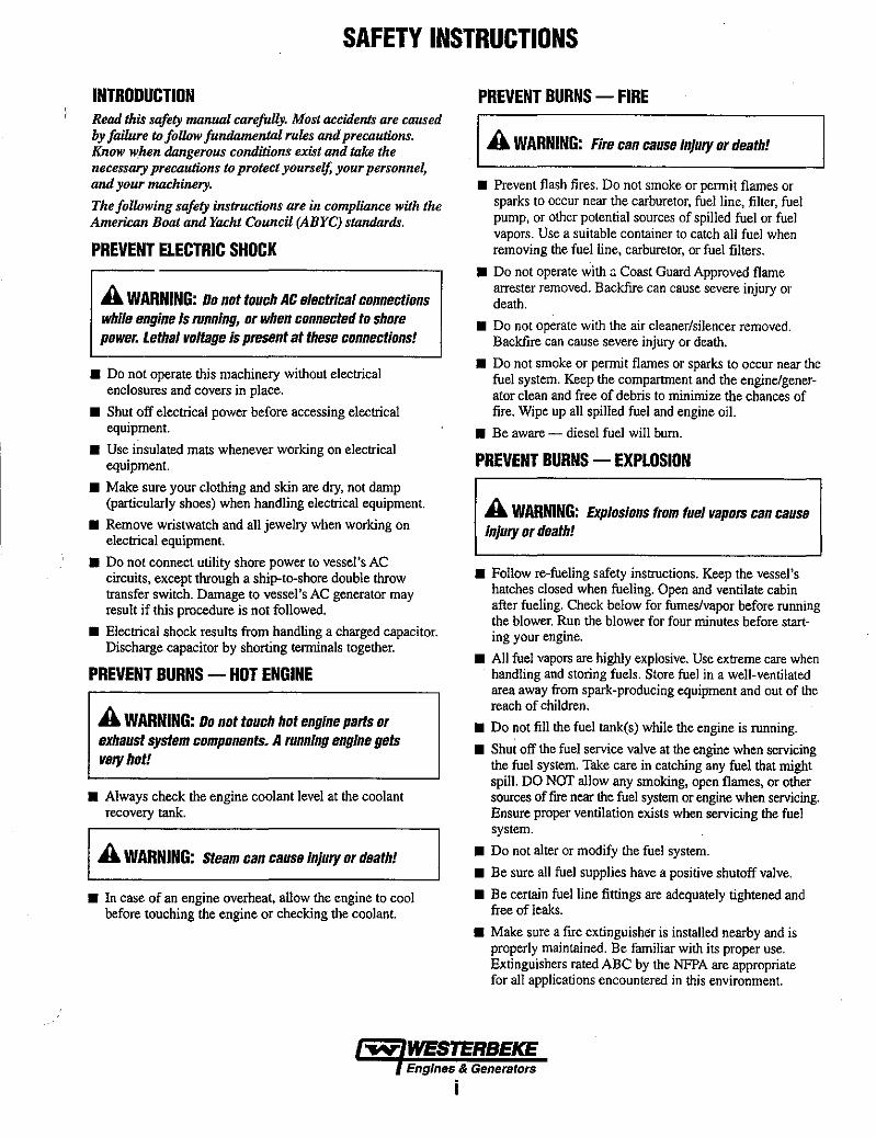
SAFETY INSTRUCTIONS
INTRODUCTION Read this safety manual carefully. Most accidents are caused by failure to follow fundamenfLll ruks and precautions. Know when dangerous conditions exist and fLliaJ the necessary precautions to protect yourself, your personnel, and your machinery.
The following safety instructions are in complimlce with the American Boat and Yacht Council (ABYC) standards.
PREVENT ELECTRIC SHOCK
A WARNING: Do not touch AC electrical connections while engine Is running, Dr when connected to shore power. Lethal voltage is present at these connections!
• Do not operate this machinery without electrical enclosures and covers in place.
• Shut off electrical power before accessing electrical equipment.
• Use insulated mats whenever working on electrical equipment.
• Make sure your clothing and skin are dry, not damp (particularly shoes) when handling electrical equipment.
• Remove wristwatch and all jewelry when working on electrical equipment.
• Do not connect utility shore power to vessel's AC circuits, except through a ship-ta-shore double throw transfer switch. Damage to vessel's AC generator may result if this procedure is not followed.
• Electrical shock results from handling a charged capacitor. Discharge capacitor by shorting terminals together.
PREVENT BURNS - HOT ENGINE
A WARNING: Do not touch hot engine parts Dr exhaust system components_ A running engine gets very hot!
• Always check the engine coolant level at the coolant recovery tank.
A WARNING: steam can cause Injury Dr death!
• In case of an engine overheat, allow the engine to cool before touching the engine or checking the coolant.
PREVENT BURNS - FIRE
A WARNING: Fire can cause injury Dr death!
• Prevent flash fires. Do not smoke or pennit flames or sparks to occur near the carburetor, fuel line, filter, fuel pump, or other potential sources of spilled fuel or fuel vapors. Use a suitable container to catch all fuel when removing the fuel line, carburetor, or fuel filters.
• Do not operate with ~ Coast Guard Approved flame arrester removed. Backfire can cause severe injury or death.
• Do not operate with the air cleaner/silencer removed. Backfire can cause severe injury or death.
• Do not smoke or permit flames or sparks to occur near the fuel system. Keep the compartment and the engine/generator clean and free of debris to minintize the chances of fire. Wipe up all spilled fuel and engine oil.
• Be aware - diesel fuel will bum.
PREVENT BURNS - EXPLOSION
A WARNING: Explosions from fuel vapors can cause Injury Dr death!
• Follow re-fueling safety instructions. Keep the vessel's hatches closed when fueling. Open and ventilate cabin after fueling. Check below for fumeslvapor before running the blower. Run the blower for four ntinutes before starting your engine.
• All fuel vapors are highly explosive. Use extreme care when handling and storing fuels. Store fuel in a well-ventilated area away from spark-producing equipment and out of the reach of children.
• Do not fill the fuel tank(s) while the engine is running.
• Shut off the fuel service valve at the engine when servicing the fuel system. Take care in catching any fuel that ntight spill. DO NOT allow any smoking, open flames, or other sources of fire near the fuel system or engine when servicing. Ensure proper ventilation exists when servicing the fuel system.
• Do not alter or modify the fuel system.
• Be sure all fuel supplies have a positive shutoff valve.
• Be certain fuel line fittings are adequately tightened and free of leaks.
• Make sure a fire extinguisher is installed nearby and is properly maintained. Be familiar with its proper use. Extinguishers rated ABC by the NFPA are appropriate for all applications encountered in this environment.
...v- WESTERBEKE Engines & Generators

SAFETY INSTRUCTIONS ACCIDENTAL STARTING
A WARNING: Accidental starting can cause injury 01 death!
• Disconnect the battery cables before servicing the engine! generator. Remove the negative lead first and reconnect it last.
• Make certain all personnel are clear of the engine before starting.
• Make certain all covers, guards, and hatches are reinstalled before starting the engine.
BAnERY EXPLOSION
A WARNING: Battery explosion can cause injury «death!
• Do not smoke or allow an open flame near the battery being serviced. Lead acid batteries emit hydrogen, a highly explosive gas, which can be ignited by elec~cal arcing or by lit tobacco products. Shut off all electncal equipment in the vicinity to prevent electrical arcing during servicing.
• Never connect the negative (-) battery cable to the positive (+) connection ternrinal of the starter solenoid. Do not test the battery condition by shorting the terminals together. Sparks could ignite battery gases or fuel vapors. Ventilate any compartment containing batteries to prevent accumulation of explosive gases. To avoid sparks, do not disturb the battery charger connections while the battery is being charged.
• Avoid conlllcting the ternrinals with tools, etc., to prevent burns or sparks that could cause an explosion. Remove wristwatch, rings, and any other jewelry before handling the battery.
• Always tum the battery charger off before disconnecting the battery connections. Remove the negative lead first and reconnect it last whenservicing the battery.
BAMRYACID
A WARNING: Sulfuric acid in batteries can cause SIWBI8 injury 01 death!
• When servicing the battery or checking the electrolyte level, wear rubber gloves, a rubber apron, and eye protection. Batteries conlllin sulfuric acid which is destructive. If it comes in conlllCt with your skin, wash it off at once with water. Acid may splash on the skin or into the eyes inadvertently when removing electrolyte caps.
TOXIC EXHAUST GASES
A WARNING: Carbon monoxide (CO) is a deadly gas!
• Ensure that the exhaust system is adequate to expel gases discharged from the engine. Check the exhaust system regularly for leaks and make sure the exhaust manifold! water-injected elbow is securely attached.
• Be sure the unit and its surroundings are well ventilated. Run blowers when running the generator set or engine.
• Don't run the generalor sel or engine unless the boat is equipped with a functioning marine carbon monoxide detector that complies with ABYCA-24. Consult your boat builder or dealer for installation of approved detectors.
• For additional information refer to ABYC T-22 (educational information on Carbon Monoxide).
A WARNING: Carbon monoxide (CO) is an invisible odorless gas. Inhalation produces flu·like symptoms, nausea or death!
• Do not use copper tubing in diesel exhaust systems. Diesel fumes can rapidly destroy copper tubing in exhaust systems. Exhaust sulfur causes rapid deterioration of copper tubing resulting in exhaust/water leakage.
• Do not install exhaust outlet-where exhaust can be drawn through portholes, vents, or air conditioners. If the engine exhaust discharge outlet is near the waterlme, water could enter the exhaust discharge outlet and close or restrict the flow of exhaust. Avoid overloading the craft.
• Although diesel engine exhaust gases are not as toxic as exhaust fumes from gasoline engines, carbon monoxide gas is present in diesel exhaust fumes. Some of the symptoms or signs of carbon monoxide inhalation or poisoning are: Vomiting Dizziness Headache Nausea
AVOID MOVING PARTS
Inability to think coherently Throbbing in temples Muscular twitching Weakness and sleepiness
A WARNING: Rotating parts can cause Injury or death!
• Do not service the engine while it is running. If a situation arises in which it is absolutely necessary to make operating adjustments, use extreme care to avoid touching moving parts and hot exhaust system components.
Engines & Generators
ii

SAFETY INSTRUCTIONS
• Do not wear loose clothing or jewelry when servicing equipment; avoid wearing loose jackets, shirts, sleev~. rings, necklaces or bracelets that could be caught in moving parts.
• Make sure all attaching hardware is properly tightened. Keep protective shields and guards in their respective places at all times.
• Do not check fluid levels or the drive belts' tension while the engine/generator is operating.
• Stay clear of the drive shaft and the transmission coupling when the engine is running; hair and clothing can easily be caught in these rotating parts.
HAZARDOUS NOISE
A WARNING: High noise levels can cause hearing loss!
• Never operate a generator without its muffler installed.
• Do not run an engine with the air intake (silencer) removed.
• Do not run engines or generators for long periods with their enclosures open.
A WARNING: Do not work on machInery when you am mentally or physically Incapacitated by fatigue!
OPERATORS MANUAL Many of the preceding safety tips and warnings are repeated in your Operators Manual along with other cautions and notes to highlight critical information. Read your manual carefully, maintain your equipment, and follow all safety procedures.
GASOLINE ENGINE AND GENERATOR INSTALLATIONS Preparations to install a gasoline engine or generator should begin with a thorough examination of the American Boat and Yacht Council's (ABYC) standards. These standards are from a combination of sources including the USCG and the NFPA.
Sections of the ABYC standards of particular interest are:
H-2 Ventilation H-24 Gasoline fuel systems P-I Exhaust systems P-4 Inboard engines E-9 DC Electrical systems
All installations must comply with the Federal Code of Regulations (FCR).
ABYC, NFPA AND USCG PUBLICATIONS FOR INSTALLING GASOLINE AND DIESEL ENGINES AND GENERATORS Read the following ABYC, NFPA and USCG publications for safety codes and standards. Follow their recommendations when installing your WESTERBEKE engine/generator.
ABYC (American Boat and Yacht Council) "Safety Standards for Small Craft"
Order From: ABYC 3069 Solomon's Island Rd. Edgewater, MD 21037
NFPA (National Fire Protection Association) "Fire Protection Standard for Motor Craft"
Order From: NFPA 1 Batterymarch Park P.O. Box 9101 Quincy, MA 02269-9101
USCG (United States Coast Guard) "USCG 33CFR183"
Order From: U.S. Government Printing Office Washington, D.C. 20404
.... WESTERBEKE Engines & Generators
iii

)
)
)

TABLE OF CONTENTS
Engine Specifications ............................................ 2 Testing for Overhaul ............................................... 3 Troubleshooting Guide ....................................... .4
Safety Shutdown Switches .................................. 6 High RPM Shutdown Switch ................................ 7 Disassembly and Assembly Procedures ............. 8 Bolt Tightening Methods ..................................... 9 Engine Disassembly, Inspection & Assembly ... 10
Timing Belt Inspection & Replacement.. ....... 10 Removing Exterior Assemblies ...................... 13
Engine Disassembly, Inspection & Assembly ... 15 Distributor .......................................................... 29 Testing the Igniter ............................................. 30
DC Electrical System .......................................... .31 Alternator Troubleshooting ............................ 31 Generator Schematic ...................................... 33 Wiring Diagram ............................................ :.34 Remote Start Diagram .................................... 35 Remote Instrument Panel Diagram .......... .36-37
Engine AdJustments .......................................... .38 Oil Pressure ................................................... .38 Ignition Timing .............................................. .39 Valve Clearance ............................................. .39 Compression Test .......................................... .39 Drive Belt ...................................................... .40 Spark Plugs .................................................... .40 High Tension Cords ....................................... .40 Carburetor ...................................................... .41 Governor ........................................................ .42
Mando Alternator ........................................ .43-49
Starter Motor ........................................................ 50 Generator ...................................................... 52-60 Service Specifications ...................................... 61 Torque Speciflcations ..................................... 63-66 Sealants and Lubricants ................................... 64 Metric Conversions ...................................... 65~67 Special Tools .................................................... 68 Index .................................................................. 69
~ WESTERBEKE Engines & Generators
1
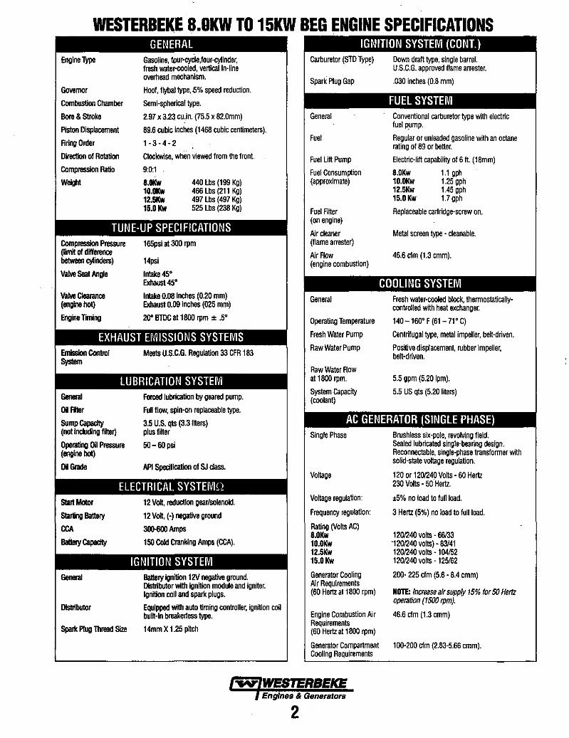
WESTERBEKE 8.0KW TO 15KW BEG ENGINE SPECIFICATIONS
Engine Type
Governor
Combustion Chamber
Bore & Stroke
Piston Displacement
Aring Onter
Direcllon of Rolation
Compression Ratio
Weight
GENERAL Gasoline, four-cycle,four-cyJinder, fresh water-cooled, vertical in-line overhead mechanism,
Hoof, flybaJ type,<i% speed reduction,
Semi-spherical type,
2,97 x 3,23 cu,in, (75,5 x 82,Omm)
89,6 cubic Inches (1468 cubic centimeters),
1-3-4-2
Clockwise, when viewed from the front.
9:0:1
8.OKw 10.OKw 12.5Kw 15.0 Kw
440 lbs (199 Kg) 466 Lbs (211 Kg) 497 Lbs (497 Kg) 525 Lbs (238 Kg)
TUNE-UP SPECIFICATIONS Compression Pressure (11mK of difference between cylinders)
Valve Seal Angle
vaJvo Clealance (engine hot)
Engine Timing
General
Oil FIller
SUmp Gapacity (not Including fiKer)
Operating Oil Pressure (engine hot)
Oil Glade
165psi at 300 rpm
14psi
Inlake45° Exhaust 450
Iniake 0.08 inchas (0.20 mm) Exhaust 0.09 inches (025 mm)
20" BlDC at 1800 rpm ± .50
Forced lubrication by geared pump.
Full flow, spin-on replaceable type.
3.5 U.S. qts (3.3IKers) plus llKer
50-60 psi
API Specification of SJ class.
ELECTRICAL SYSTEMQ StaJlMotor
Starting BatleIY
CCA
BaileIY Gapacity
General
Distributor
Spark Plug Thread Size
12 Volt, reduction gear/solenoid,
12 Volt, (-) negative ground
3O(Hj()() Amps
150 Cold Cranking Amps (CCA).
IGNITION SYSTEM BatleIY Ignitionl2V negative ground, Distributor with Ignhion module and ignher. Ignition coli and spark plugs,
Equipped with auto timing controller, ignition coil buih-in breake~ess type.
14mm X 1.25 pitch
IGNITION SYSTEM (CONT.) Carburetor (STD Typ!)
Spark Plug Gap
General
Fuel
Fuel Lift Pump
Fuel Consumption (approximate)
Fuel Rher (on engine)
I'jr cleaner (ilame arrester)
I'jr Row (engine combustion)
General
Operating Temperature
Fresh Water Pump
Raw Water Pump
Raw Water Row at 1800 rpm,
System Capacity (coolant)
Down draft type. single barrel. U,S,C.G. approved flame arrester,
,030 inches (0.8 mm)
FUEL SYSTEM Conventional carburetor type with electric fuel ~ump,
Regular or unleaded gasoline with an octane rating of 89 or better,
Electric-lift capability of 6 ft, (18mm)
8.0Kw 1,1 gph 10.0Kw 1.25 gph 12.5Kw 1,45 gph 15.0 Kw 1.7 gph
Replaceable cartridge-screw on,
Metal screen type • cleanable,
46,6 elm (1.3 cmm),
COOLING SYSTEM Fresh water-cooled block, thermostaticallycontrolled whh heat exchanger,
140 -1600 F (61-71 0 C)
Centrifugal type, metal impeller, beh-driven,
Positive displacement, rubber impeller, beh-driven,
5,5 gpm (5.20 Ipm),
5,5 US qts (5,20 liters)
AC GENERATOR (SINGLE PHASE) Single Phase
Vohage
Vohage regulation:
Frequency regulation:
Rating (Voks AC) 8.0Kw 10.0Kw 12.5Kw 15.0 Kw
Generator Cooling I'jr Requirements (60 Hertz at 1800 rpm)
Engine Combustion Air Requirements (60 Hertzat 1800 rpm)
Brushless Six-pole, revoMng field, Sealed lubricated Single-bearing design, Reconnactable, single·phase transformer whh solid-state vohage regulation,
120 or 1201240 Voks - 60 Hertz 230 Volts - 50 Hertz.
.5% no load to full load,
3 Hertz (5%) no load to full load,
1201240 voks - 66133 '1201240 voks) - 83/41 1201240 voks -104152 1201240 voks -125162
200- 225 elm (5,6' B.4 cmm)
NOTE: Increase air supply 15% for 50 Hertz operaUon (1500 tpm),
46,6 elm (1.3 cmm)
Generator Compartment 100-200 elm (2,83-5,66 cmm), Cooling Requirements
....v' WESTERBEKE Engines & Generators
2

TESTING FOR OVERHAUL HOW TO DETERMINE ENGINE OVERHAUL PERIOD Cause of Low Compression Generally, the time at which an engine should be overhauled is detennined by various conditions such as lowered engine power output, decreased compression pressure, and increased fuel and oil consumption. The lowered engine power output is not necessarily due to trouble with the engine itself, but is sometimes caused by wom plugs or fueVcarburetor problems .. The decrease in compression pressure is caused by many factors. It is, therefore, necessary to detennine a cause or causes on the basis of data produced by periodic inspection and maintenance. Oil analysis on a seasonal basis is a good means of monitoring engine internal wear. When caused by wom cylinders or piston rings, the following symptoms will occur:
1 Low engine power output 2 Increased fuel consumption 3 Increased oil consumption 4 Hard engine starting 5 Noisy engine operation
These symptoms often appear together. Symptoms 2 and 4 can result also from carburetor performance or worn plugs. They are caused also by defective electrical devices such as the battery, alternator or starter. Therefore it is desirable to judge the optimum engine overhaul time by the lowered compression pressure caused by worn cylinders and pistons plus increased oil consumption. Satisfactory combustion is obtained only under sufficient compression pressure. If an engine lacks compression pressure, incomplete combustion of fuel will take place even if other parts of the engine are operating properly. To detennine the period of engine overhaul, it is important to measure the engine compression pressure regularly. At the same time, the engine speed at which the measurement of compression pressure is made should be checked because the compression pressure varies with engine rpm. The engine rpm can be measured at the front end of the crankshaft.
When the decrease of compression pressure reaches the repair limit, the engine must be overhauled.
The engine requires overhaul when oil consumption is high, blow-by evident, and compression valves are at minimum or below.
NOTE: Make cenain the engines valve clearances are properly adjusted. An incorrect valve clearance can cause symptoms that might, incorrectly, suggest an engine overhaul (cylinder misfire, white smoke, noise, etc).
Before preparing for an engine overhaul, adjust the valve clearances to the correct specification. install a new cover gasket and test the engine.
DISASSEMBLY NOTE: Before disassembly and cleaning, carefully check for defects which cannot be found after disassembly and cleaning.
• All disassembled parts should be carefully arranged in the order of reassembly. Mark or label the parts as needed to insure proper mating and reassembly in the proper directions and positions.
• If the disassembly procedure is complex requiring many parts to be disassembled, the parts should be disassembled in a way that will allow them to be efficiently reassembled without any change in the engine's extemal appearance or its performance.
• Do not remove or disassemble parts that require no disassembly.
• Carefully inspect each parts after removal for damage, deformation, and other problems.
• Carefully check gaskets, packings and oil seals, even if checking is not specified. Replace with new ones if defective.
• Be careful not to damage the disassembled parts. Keep the parts clean.
• Use the proper tools. Apply oil when necessary. Take special care to keep the fuel system parts free from the intrusion of dust and dirt.
-..v: WESTERBEKE Engines & Generators
3
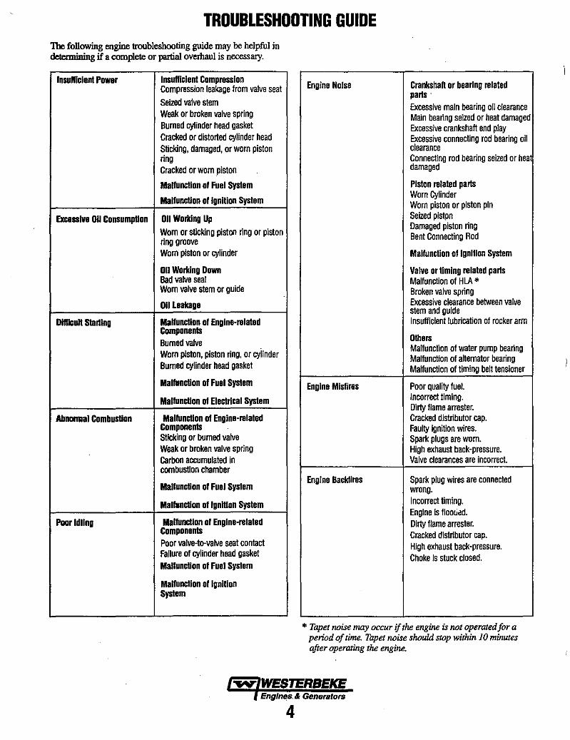
TROUBLESHOOTING GUIDE The following engine troubleshooting guide may be helpful in detennining if a complete or partial overhaul is necessary.
Insomclen! Power InsuHlclen! Compression Compression leakage from valve seat Seized valve stem Weak or broken valve spring Burned cylinder head gasket Cracked or distorted cylinder head Sticking, damaged, or worn piston ring Cracked or worn piston
Malfunction of Fuel System
Malfunction ollgnllion System
Excessive 011 Consumption 011 Worklng Up Worn or sUcking piston ring or piston ring groove Worn plslon or cylinder
011 Worklng Down Bad valve seal Worn valve stem or guide
011 Leakage
Dlfllcull starting Malfunction 01 Englne-relaled Components Burned valve Worn pislon, plslon ring, or cylinder Burned cylinder head gasket
Mallunctlon 01 Fuel System
Mallunction of Electrical System
Abnonnal Combusllon Mallunction of Engine-mlaled Components SUcking or burned valve Weak or broken valve spring Carbon accumulated in combusllon chamber
Malfuncllon 01 Fuel Syslem
Mallunctlon ollgnillon Syslem
Poor Idling Mallunctlon of Englne-mlaled Components Poor valve-to-valve seal contact Failure of cylinder head gasket Malfunction of Fuel Syslem
Malfunction of Ignition System
Engine Noise Crankshaft or bearing mlaled parts . Excessive main bearing oil clearance Main bearing seized or heat damaged Excessive crankshaft end play Excessive connecting rod bearing oil clearance Connecting rod bearing seized or hea damaged
Piston mlaled parts Worn Cylinder Worn piston or piston pin Seized plstpn Damaged piston ring Bent Connecting Rod
Malfuncllon ollgnilion Syslem
Valve or timing relaled parts Malfunction of HLA * Broken valve spring Excessive clearance between valve stem and guide InsuHlcient lubrication of rocker arm
Others Malfunction of water pump bearing Malfunction of attemator bearing Malfunction of timing belt tensioner
Engine Misfires Poor quality fuel. Incorrect timing. Dirty flame arrester. Cracked distributor cap. Faulty Ignnlon wires. Spark plugs are worn. High exhaust back-pressure. Valve clearances are incorrect.
Engine Backfires Spark plug wires are connected wrong. Incorrect timing. Engine is flootiad. Dirty flame arrester. Cracked distributor cap. High exhaust back-pressure. Choke Is stuck closed.
* Tapet noise may occur if the engine is not operated for a period of time. Tapet noise should stop within J 0 minutes after operating the engine.
Engln"s. & Generators
4
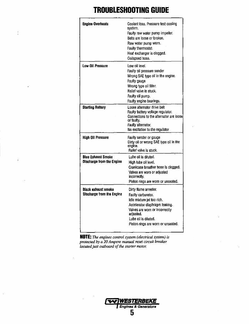
TROUBLESHOOTING GUIDE
Engine Overheats Coolant loss. Pressure test cooling system. Faulty raw water pump impeller. Belts are loose or broken. Raw water pump worn. Faulty thermostat. Heat exchanger is clogged. Collapsed hose.
Low 011 Pressure Low oil level. Faulty oil pressure sender Wrong SAE type oil in the engine. Faulty gauge Wrong type oil filter. Relief valve is stuck. Faulty oil pump. Faulty engine bearings.
Starting Battery Loose alternator drive belt Faulty battery voltage regulator. Connections to the alternator are loose or faulty. Faulty alternator. No excitation to the regulator
High 011 Pressure Faulty sender or gauge Di';% oil or wrong SAE type oil in the eng ne. Relief valve is stuck.
Blue Exhaust Smoke Lube oil is diluted. Discharge from the Engine High lube oil level.
Crankcase breather hose is clogged. Valves are worn or adjusted incorrectly. Piston rings are worn or unseated.
Black exhaust smoke Dirty flame arrester. Discharge from the Engine Faulty carburetor.
Idle mixture jet too rich. Accelerator diaphragm leaking. Valves are worn or incorrectly adjusted. Lube oil is diluted. Piston rings are worn or unseated.
NOTE: The engines control system (electrical system) is protected by a 20 Ampere manual reset circuit breaker located just outboard of the starter motor.
-..v- WESTERBEKE Englnes'& Generators
5
SAFETY SHUTDOWN SWITCHES
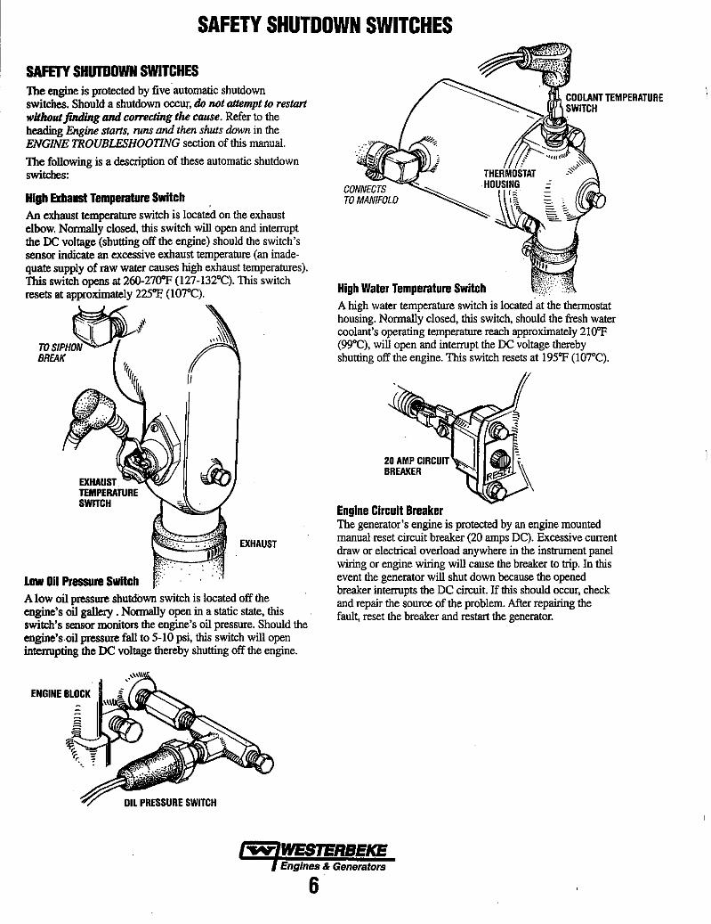
SAFETY SHUTDOWN SWITCHES The engine is protected by five automatic shutdown switches. Should a shutdown occur, do not attempt to restart witlwut jinding and co"ecting the cause. Refer to the heading Engine stans, runs and then shuts down in the ENGINE TROUBLESHOOTING section of this manual.
The following is a description of these automatic shutdown switches:
High Exhaust Temperature Switch An exhaust temperature switch is located on the exhaust elbow. Normally closed, this switch will open and interrupt the DC voltage (shutting off the engine) should the switch's sensor indicate an excessive exhaust temperature (an inadequate supply of raw water causes high exhaust temperatures). This switch opens at 26O-27O"F (l27-132°C). This switch resets at approximately 225"F. (\o7°C).
EXHAUST
low Oil Pressure SwItch A low oil pressure shutdown switch is located off the engine's oil gallery . Nonnally open in a static state, this switch's sensor monitors the engine's oil pressure. Should the engine's.oil pressure fall to 5-10 psi, this switch will open interrupting the DC voltage thereby shutting off the engine.
ENGINE BLOCK
High Water Temperature Switch A high water temperature switch is located at the thermostat housing. Normally closed, this switch, should the fresh water coolant's operating temperature reach approximately 2\o'F (99°C), will open and interrupt the DC voltage thereby shutting off the engine. This switch resets at 195'F (107°C).
20 AMP .'."IIIT·" BREAKER
Engine Circuit Breaker The generator's engine is protected by an engine mounted manual reset circuit breaker (20 amps DC). Excessive current draw or electrical overload anywhere in the instrument panel wiring or engine wiring will cause the breaker to trip. In this event the generator will shut down because the opened breaker interrupts the DC circuit. If this should occur, check and repair the source of the problem. After repairing the faul~ reset the breaker and restart the generator.
~ WESTERBEKE Engines & Generators
6
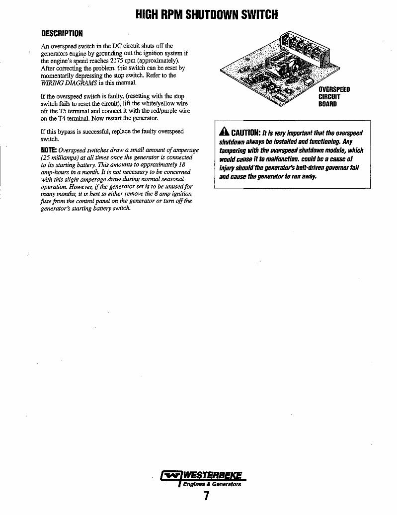
HIGH RPM SHUTDOWN SWITCH DESCRIPTION An overspeed switch in the DC circuit shuts off the generators engine by grounding out the ignition system if the engine's s~ reaches 2175 rpm (approximately). After correcting the problem, this switch can be reset by momentariJy depressing the stop switch. Refer to the WIRING DIAGRAMS in this manual.
If the overspeed switch is faulty, (resetting with the stop switch fails to reset the circuit), lift the white/yellow wire off the T5 terminal and connect it with the redlpurple wire on the T4 terminal. Now restart the generator.
If this bypass is successful, replace the faulty overspeed switch.
NOTE: Overs peed switches draw a small amaunt of amperage (25 milliamps) at all times once the generator is connected to its starting battery. This amounts to approximately 18 amp-hnurs in a month. It is not necessary to be concerned with this slight amperage draw during normal seasonal operation. However, if the generator set is to be unused for many months, it is best to either remove the 8 amp ignition fuse from the control panel on the generator or tum off the generator~ starting battery switch.
OVERSPEEO CIRCUIT BOARD
A CAUTION: It is very important that the overspeed shutdown always be instal/ed and functioning. Any tampering with the overspeed shutdown module, which would cause it to malfunction. could be a cause of injury should·the generator's belt·driven governor fail and cause the generator to run away.
~ WESJERBEKE Engines & Generators
7
DISASSEMBLY AND ASSEMBLY PROCEDURES DISASSEMBLY • Before disassembly and cleaning, carefully check for
defects which cannot be found after disassembly and cleaning.
• Drain water, fuel and oil before disassembly.
• Clean or wash the engine exterior.
• Do not remove or disassemble parts. • Perform disassembly in a proper order using proper tools.
Keep disassembled parts in order. Apply oil when necessary. Take special care to keep the fuel system parts from intrusion of dust and dirt.
• Parts must be restored to their respective components from which they were removed at disassembly. This means that all parts must be set aside separately in groups, each IIllIIked for its component, so that the same combination or set can be reproduced at assembly.
• Pay attention to marks on assemblies, components and parts for their positions or directions. Put on marks, if necessary, to aid assembly ..
• Carefully check each part or component for any sign of faulty condition during removal or cleaning. The part will tell you how it acted or what was abnormal about it more accurately dm!ng removal or cleaning.
ASSEMBLY • Wash aU parts, except for oil seals, O-rings,and rubber
gaskets with cleaning solvent and dry them with air pressure .
• Always use tools that are in good condition and be sure you understand how to use them before performing any job.
• Use only good quality lubricants. Be sure to apply a coat of oil, grease or sealant to parts as specified ..
• Be sure to use a torque wrench to tighten parts for which torques are specified.
• When the engine is assembled,install new gaskets and O-rings.
TORQUING DATA Parts of the engine use plastic region tightening bolts. The tightening procedure for these is different from that of conventional bolts and is described in this manual, Note that plastic region tightening bolts have fixed service limitS. These limits are indicated in this manual and must be strictly observed.
• Plastic region tightening bolts are used for the following applications: 1. Cylinder head bolts
2. Connecting rod cap bolts
• The tightening procedure is basically as follows: After tightening a bolt to the specified torque, tighten it by a further 90" + 90" or by a further 90-100". The exact tightening procedure differs depending on the bolt and is described where it applies in this manual.
GASKET INFORMATION The engine has several areas where form-in-place RTV silicone gaskets are used such as LOCTITE 598 or GE RTV 100. To ensure that the gasket fully serves its pmpose, it is necessary to observe some precaution when applying the gasket. Bead size, continuity and location are very important. Too thin a bead could cause leaks and too thick a bead could be squeezed out of location causing blocking or narrowing of the fluid feed lines. To eliminate the possibility of leaks from a joint, it is necessary to apply the gasket evenly without a break while observing the correct bead size.
The gasket material used in the engine is a room temperature vulcanization (RTV) type and is supplied in a l40z (400 gram) applicator/tube. The RTV hardens as it reacts with the moisture in the atmospheric air and can be used for sealing both engine oil and coolant assemblies.
Disassembly The parts assembled with the silicone can be easily disassembled without use of a special method. In some cases, however, the sealant between the joined surfaces may have to be broken by lightly striking with a mallet or similar tool. A flat and thin gasket scraper may be lightly hammered in between the joined surfaces. In this case, care must be taken to prevent damage to the joined surfaces. For removal of the oil pan, use a special "oil pan remover".
Surface Preparation Thoroughly remove all substances deposited on the gasket application surfaces using a gasket scraper or wire brush. Check to ensure that the surfaces to which the silicone gasket is to be applied is flat. make sure that there are no oils, greases and foreign substances deposited on the application surfaces. Do not forget to remove the old sealant that remains in the bolt holes.
Form-in-place Gasket Application When assembling parts with the silicone gasket, you must observe some precautions but the procedures are very simple as in the case of a conventional precut gasket.
The applied gasket bead should be the specified size and without breaks. Be sure to encircle the bolt hole circumference with a completely continuous bead. The gasket material can be wiped away unless it has hardened. While the gasket is still moist, mount the parts in position. When the parts are mounted, make sure that the gasket is applied to the required area only. Do not apply oil or water to the sealing locations or start the engine until a sufficient amount of time has passed after installation is completed.
The gasket application procedure may vary on different areas. Observe the procedure described in the text when applying the gasket silicone and follow the directions on the applicator/tube.
".. WESTERBEKE Engines & Generators
8
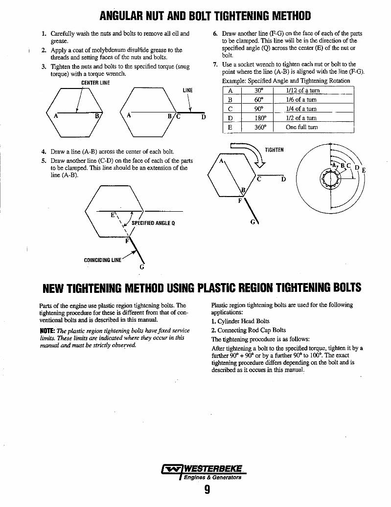
ANGULAR NUT AND BOLT TIGHTENING METHOD 1. Carefully wash the nuts and bolts to remove all oil and
grease. 2. Apply a coat of molybdenum disulfide grease to the
threads and setting faces of the nuts and bolts.
3. Tighten the nuts and bolts to the specified torque (snug torque) with a torque wrench.
CENTER LINE LINE
-"--:).l C D
4. Draw a line (A-B) across the center of each bolt. 5. Draw another line (C-D) on the face of each of the parts
to be clamped. This line should be an extension of the line (A-B).
COINCIDING LINE G
6. Draw another line (F-G) on the face of each of the parts to be clamped. This line will be in the direction of the specified angle (Q) across the center (E) of the nut or bolt.
7. Use a socket wrench to tighten each nut or bolt to the point where the line (A-B) is aligned with the line (F-G).
Example: Specified Angle and Tightening Rotation
A 3D· 1/12 of a tum
B 60· 1I6 of a tum
C 90· 1I4 of a tum
D 180· 1I2 of a tum
E 360· One full tum
NEW TIGHTENING METHOD USING PLASTIC REGION TIGHTENING BOLTS Parts of the engine use plastic region tightening bolts. The tightening procedure for these is different from that of conventional bolts and is described in this manual.
NOTE: The plastic region tightening bolts have fixed service limits. These limits are indicated where they occur in this manual and must be strictly observed.
Plastic region tightening bolts are used for the following applications: 1. Cylinder Head Bolts 2. Connecting Rod Cap Bolts The tightening procedure is as follows: After tightening a bolt to the specified torque, tighten it by a further 90· + 90· or by a further 90" to 100·. The exact tightening procedure differs depending on the bolt and is described as it occurs in this manual.
Engines & Generators
9
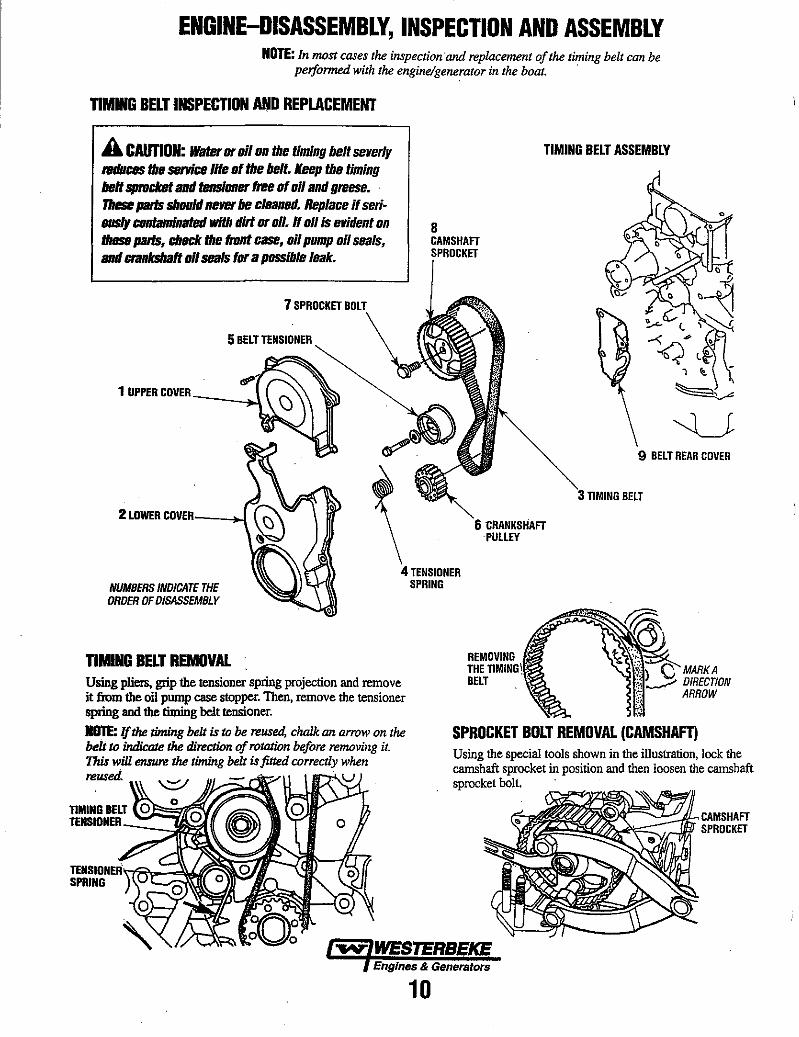
ENGINE-DISASSEMBLY, INSPECTION AND ASSEMBLY NOTE: In TlU)st cases the inspection 'and replacement of the timing belt can be
peiformed with the engine/generator in the boat. '
TIMING BELT INSPECTION AftID REPLACEMENT
A CAUTION: water or oil on the timing belt severly reduces the service life of the belt. Keep the timing belt sprocket ami fensloner free of 011 and greese. ' These paris should never be cleaned. Replace if serio ousIy contaminated with dirt or oil. If ollis evident on these paris, check the front case, oil pump oil seals, ami ctankshaft 011 seals for a possible leak.
7 SPROCKET BOLT
5 BELT TENSIONER
1 UPPER COVER --~..\.
8 CAMSHAFT
TIMING BELT ASSEMBLY
9 BELT REAR COVER
2 LOWER COVER_---l~ CRANKSHAFT 'PULLEY
TIMING BELT
NUMBERS INDICATE THE ORDER OF DISASSEMBLY
4 TENSIONER SPRING
TIMING BELT REMOVAL Using pIiets, grip the tensionet spring projection and remove it from the oil pump case stopper. Then, remove the tensioner spring and the timing belt tensionet.
NOTE: If the timing belt is to be reused, chalk an arrow on the belt to indicaJe the direction of roll1tWn before reTlU)ving it. This will eIISIU'E the timing belt is fitted correctly when reused. • u)
MARKA DIRECTION ARROW
SPROCKET BOLT REMOVAL (CAMSHAFT) Using the special tools shown in the illustration, lock the camshaft sprocket in position and then loosen the camshaft sprocket bolt.
CAMSHAFT SPROCKET
Engines & Generators
10
ENGINE-DISASSEMBLY, INSPECTION AND ASSEMBLY NOTE: In most cases the inspection and replacement of the timing belt can be
performed with the engine/generator in the boat.
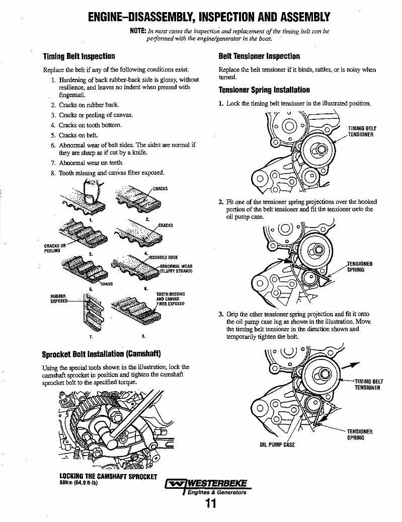
Timing Belt Inspection
Replace the belt if any of the following conditions exist:
1. Hardening of back rubber-back side is glossy, without resilience, and leaves no indent when pressed with fmgernail.
2. Cracks on rubber back.
3. Cracks or peeling of canvas.
4. Cracks on tooth bottom.
5. Cracks on belt.
6. Abnonnal wear of belt sides. The sides are normal if they are sharp as if cut by a knife.
7: Abnormal wear on teeth.
8. Tooth missing and canvas fiber exposed.
~ CRACKS 08 PEEUNG
5.
RUBBER ___ : "'. " ' ... EXPOSED .: .~: .. :
;: .. ~ .. :~~.
: .: .... ~~~
7.
6.
••
Sprocket Bolt Installation (Camshaft)
Using the special tools shown in the illustration, lock the camshaft sprocket in position and tighten the camshaft sprocket bolt to the specified torque.
LOCKING THE CAMSHAFT SPROCKET
Belt Tensioner Inspection
Replace the belt tensioner if it binds, rattles, or is noisy when turned.
TensionerSpring Installation
1. Lock the timing belt tensioner in the illustrated position.
TIMING BELT TENSIDNER
2. Fit one of the tensioner spring projections over the hooked portion of the belt tensioner and fit the tensioner onto the oil pump case.
NSIDNER SPRING
3. Grip the other tensioner spring projection and fit it onto the oil pump case lug as shown in the illustration. Move the timing belt tensioner in. the direction shown and temporarily tighten the bolt.
OIL PUMP CASE
TENSIDNER SPRING
88Nm (64.9 n·lb) ~ WESTERBEKE . Engines & Generators
11
ENGINE-DISASSEMBLY, INSPECTION AND ASSEMBLY NOTE: In most cases the inspection and replacement of the timing belt call be
peiformed with the engine/generator in the boat.
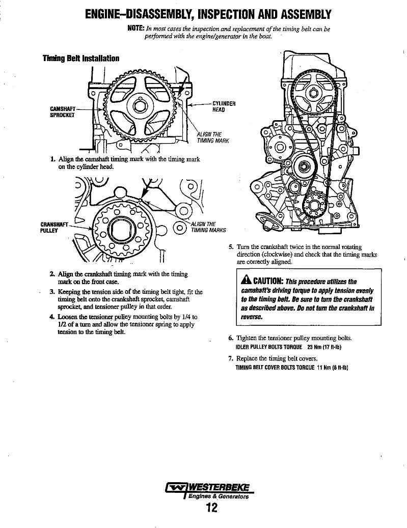
Timing Belt Installation
CAMSHAFT--f-1~\ K---CYLINDER
HEAD SPROCKET
ALIGN THE TIMING MARK
1. Align the camshaft timing mark with the timing mark on the cylinder head.
2. Align the crankshaft timing mark with the timing made on the front case.
3. Keeping the tension side of the timing belt tight, fit the timing belt onto the crankshaft sprocket, camshaft sprocket, and tensioner pulley in that order.
4. Loosen the tensioner pulley mounting bolts by 1/4 to 112 of a turn and allow the tensioner spring to apply tension to the timing belt
5. Thrn the crankshaft twice in the normal rotating direction (clockwise) and check that the tinting marks are correctly aligned.
A CAUTION: This procedure utilizes the camshaft's driving torque to apply tension evenly to the timing belt. Be sure to tum the crankshaft as described above. 00 not tum the crankshaft in reverse.
6. Tighten the tensioner pulley mounting bolts. IDLER PULLEY BOLTS TORQUE 23 Nm (17 H·lb)
7. Replace the timing belt covers. TIMING BELT COVER BOLTS TORQUE 11 Nm (8 H·lb)
~ WESTERBEKE Engines &. Generators
12

ENGINE/GENERATOR DISASSEMBLY REMOVING EXTERIOR ASSEMBLIES
DISASSEMBLY PROCEDURE Before mounting the engine on an engine stand, unbolt and remove the generator backend, Make sure the back end is properly supported, Refer to the generator section of this manual for additional information and an exploded view of the generator components. Also remove the engine flywheel before mounting the engine.
NOTE: WHEN REMOVING THE GENERATOR BACKENO, MAKE CERTAIN ITiS PROPERLY SUPPORTED UNDERNEATH
BELL HOUSING/FLYWHEEL ASSEMBLY
GASOENSER
CONTROL PANEL ,,----
GENERATOR BACKEND
Mounting the engine on a suitable engine stand and begin removing the exterior engine components.
Note the following when disassemble these components.
• Drain any engine oil or coolant left in the engine. • Clean the exterior of the engine of any deposits of dirt
and oil.
• Be careful not to damage the disassembled parts. • Arrange parts in the order of disassembly. Mark or label
parts as needed to insure proper mating and reassembly. Keep the parts clean.
DISTRIBUTOR IGNITION WIRES AND SPARK PLUGS
When rebuilding the engine, the alternator should be cleaned and inspected. The housing can be wiped off with a solvent and the alternator tenninal studs should be cleaned with a wire brush. Make certain the studs are tight and clean the wiring connections that connect to the wiring harness.
Thrn the rotor pulley by hand. It should tum smoothly.
Depending on when the alternator was last serviced, the brushes may need replacing. If the alternator is at all suspect, send it to a service shop for testing and overhaul.
For additional information on alternators, refer to the ALTERNATOR TROUBLESHOOTING "uu "Ul1~~//."="-~ SERVICE in this manual.
ALTERNATOR
,. WESTERBEKE En!1lnes & Generators
13
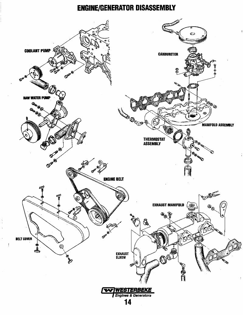
COOLANT PUMP
ENGINE/GENERATOR DISASSEMBLY
EXHAUST ELBOW
CARBURETOR
THERMOSTAT ASSEMBLY
EXHAUST MANIFOLD
..-v' WESTERBEKE Engines & Genera/ors
14

ENGINE-DISASSEMBLY, INSPECTION AND ASSEMBLY
1 pvc VALVE
3 ROCKE,R:. AssREMinBlY'~ SHAFT Ai
5 CAMSHAFT all SEAL
~ , , C- .-",'
ROCKER ARMS AND CAMSHAFT Camshaft Measure the cam heights and replace the camshaft if any height is less than the specified limit.
STANDARD VALUE: INTAKE 3B.7Bmm (1.527In) EXHAUST 39.10mm (l.5401n)
LIMIT: INTAKE 3B.2Bmm (1.50Bln) EXHAUST 3B.60mm (1.521In)
MEASURE IN ALL DIRECTIONS
ROCKER ARM /ROCKER ASSEMBLY INSTALLATION Assembly the rocker arms and rocker shaft, paying attention to the identification marks. Then, mount the assembly on the cylinder head.
ENGINE FRONT
IDENTIFICATION MARK
&. CAMSHAFT OIL SEAL INSTALLATION Using the oil seal installer tool, install the camshaft oil seal.
ADJUSTING THE VALVE CLEARANCE
NOTE: Refer to the VALVE CLEARANCE ADJUSTMENT procedure in this manual, however when adjusting the valve elearance on a cold engine, use the following data.
VALVE CLEARANCE ON A COLD ENGINE INTAKE 0.09mm (0,0035In) EXHAUST O.17mm (0.0066In)
...v' WESTERBEKE Engines & Generators
15
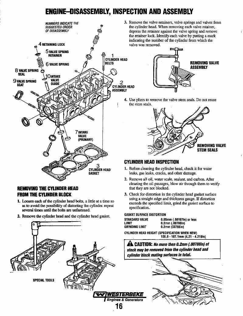
ENGINE-DISASSEMBLY, INSPECTION AND ASSEMBLY NUMBERS INDICATE THE SUGGESTED ORDER OF DISASSEMBLY
~~ 4 RETAINING LOCK
1. 5 VALVE SPRING .... RETAINER
3. Remove the valve retainers, valve springs and valves from the cylinder head. When removing each valve retainer, depress the retainer against the valve spring and remove the retainer lock. Identify·each valve by putting a mark indicating the number of the cylinder from which the valve was removed.
'16 VALVE SPRING I ~!~.~~UI'" HEAD
REMOVING VALVE ASSEMBLY 8 VALVE SPRING e,
SEAL ~OINTAKE 9 VALVE SPRING ,VALVE
SEAT GUlDE~~~~t:
REMOVING THE CYUNOER HEAD FROM THE CYUNOER BLOCK
3 CYLINDER HEAD GASKET
1. Loosen each of the cylinder head bolts, a little at a time so as to avoid the possibility of distorting the cylinder. repeat several times until the bolts are unfastened.
2. Remove the cylinder head and the cylinder head gasket.
SPECIAL TOOLS
4. Use pliers to remove the valve stem seals. Do not reuse the stem seals.
CYLINDER HEAD INSPECTION 1. Before cleaning the cylinder head, check it for water
leaks, gas leaks, cracks, and other damage.
2. Remove all oil, water scale, sealant, and carbon. After c1earting the oil passages, blow air through them to verify that they are not blocked.
3. Check for distortion in the cylinder head gasket surface using a straight edge and thickness gauge. If distortion exceeds the specified limit, grind the gasket surface to specification.
GASKET SURFACE DISTORTION STANDARD VALVE 0.05mm (.00197In) Dr les. LIMIT 0.2mm (.00788In) GRINDING LIMIT 0.2mm (00788In)
CYLINDER HEAD HEIGHT (SPECIFICATION WHEN NEW) 106.9 ·107.1mm (4.21 • 4.219In).
A CAUTION: No more then O.2mm (.00788In) of stock may be removed frilm the cylinder head and cylinder block mating surfaces In total.
"'-=:-------'
...v: WESTERBEKE Engines & Generators
16
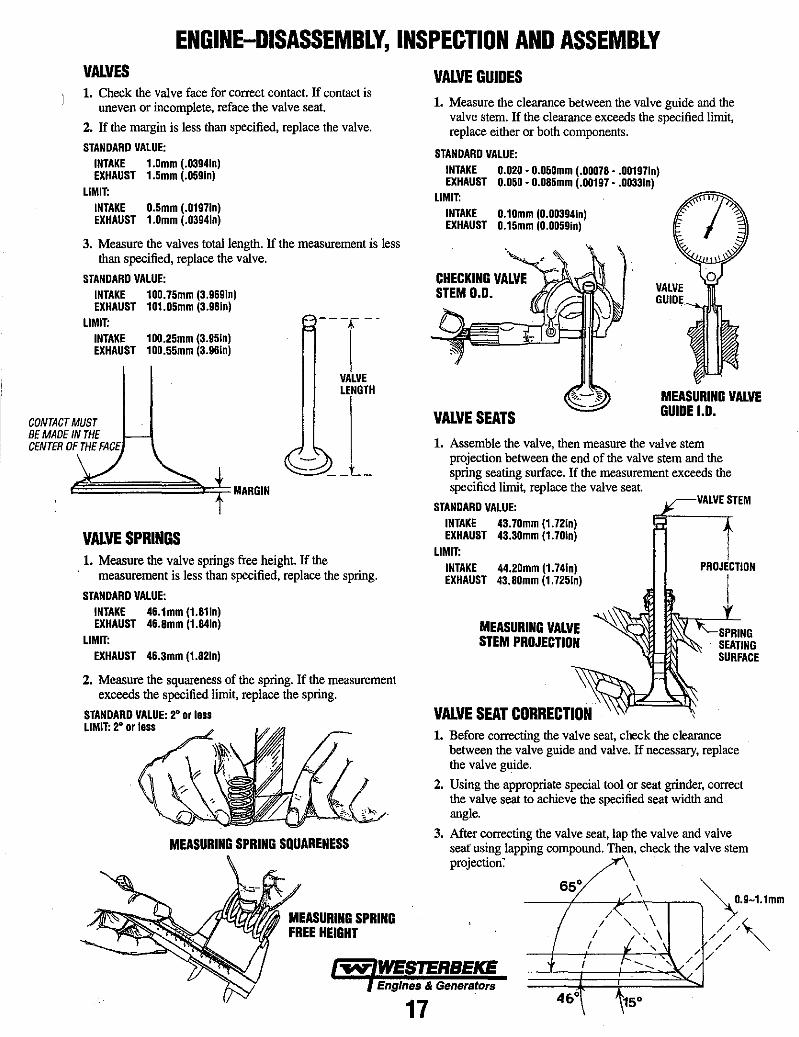
ENGINE-DISASSEMBLY, INSPECTION AND ASSEMBLY VALVES 1. Check the valve face for correct contact. If contact is
uneven or incomplete, reface the valve seat.
2. If the margin is less than specified, replace the valve.
STANDARD VALUE: INTAKE 1.0mm (.0394In) EXHAUST 1.Smm (.OS9In)
LIMIT: INTAKE O.Smm (.0197In) EXHAUST 1.0mm (.0394In)
3. Measure the valves total length. If the measurement is less than specified, replace the valve.
STANDARD VALUE: INTAKE 100.7Smm (3.969In) EXHAUST 101.0Smm (3.98In)
LIMIT: INTAKE 100.2Smm (3.9Sln) EXHAUST 100.5Smm (3.9Sln)
CONTACT MUST BE MAOE IN THE CENTER OF THE FACE
VALVE SPRINGS
- --T--
VALVE LENGTH
1. Measure the valve springs free height. If the measurement is less than specified, replace the spring.
STANDARD VALUE: INTAKE 4S.1mm (l.81In) EXHAUST 4S.8mm (1.84In)
LIMIT: EXHAUST 4S.3mm (l.82In)
2. Measure the squareness of the spring. If the measurement exceeds the specified limit, replace the spring.
STANDARD VALUE: 2' or 10 •• LIMIT: 2' or 10 ..
MEASURING SPRING SQUARENESS
MEASURING SPRING FREE HEIGHT
VALVE GUIDES 1. Measure the clearance between the valve guide and the
valve stem. If the clearance exceeds the specified limit, replace either or both components.
STANDARD VALUE: INTAKE 0.020· O.OSOmm (.00078 •• 00197In) EXHAUST O.OSO· 0.08Smm (.00197 •• 0033In)
LIMIT: INTAKE 0.10mm (O.00394In) EXHAUST O.lSmm (0.00S9In)
CHECKING VALVE STEM 0.0.
VALVE SEATS MEASURING VALVE GUIDE 1.0.
1. Assemble the valve, then measure the valve stem projection between the end of the valve stem and the spring seating surface. If the measurement exceeds the specified limi~ replace the valve seat.
STANDARD VALUE: INTAKE 43.70mm (l.72In) EXHAUST 43.30mm (l.701n)
LIMIT: INTAKE 44.20mm (l.74In) EXHAUST 43.80mm (l.72Sln)
MEASURING VALVE STEM PROJECTION
VALVE SEAT CORRECTION
VALVE STEM
PRDJECTION
I
1. Before correcting the valve sea~ check the clearance between the valve guide and valve. If necessary, replace the valve guide.
2. Using the appropriate special tool or seat grinder, correct the valve seat to achieve the specified seat width and angle.
3. After correcting the valve seat, lap the valve and valve sear using lapping compound. Then. check the valve stem projection:
\ 65° ~
__ -I-__ /~?-\~\---' __ ) ')~.9-1.1mm
/ " ~ I "\ /// / I " / /
...v: WESTERBEKE ---+---+----~---~~, / /
Engines & Generators
17 4&°
ENGINE-DISASSEMBLY, INSPECTION AND ASSEMBLY
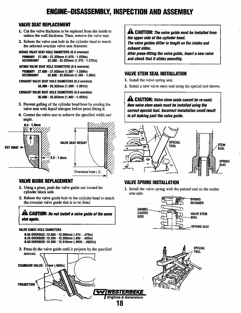
VAlVE SEAT REPLACEMENT 1. Cut the valve thickness to be replaced from the inside to
reduce the wall thickness. Then, remove the valve seat.
2. Rebore the valve seat hole in the cylinder head to match the selected oversize valve seat diameter.
INTAKE VALVE SEAT HOLE DIAMETERS (0.3 ov ... lz.) PRIMARY 27.300· 27.325mm (1.075 ·1.07610) SECONDARY 32.300· 32.325mm (1.272 ·1.27310)
INTAKE VALVE SEAT HOLE DIAMETERS (0.6 ov ... lz.) PRIMARY 27.600· 27.625mm (1.087 ·1.08810) SECONDARY 32.600· 32.625mm (1.284 -1.2810)
EXHAUST VALVE SEAT HOLE DIAMETERS (0.3 ove .. lz.) 35.300· 35.325mm (1.390 ,1.39110)
EXHAUST VALVE SEAT HOLE DIAMETERS (0.6 ove .. lz.) 35.600 • 35.625mm (1.402 • 1.40310)
3. Prevent galling of the cylinder head bore by cooling the valve seat with liquid nitrogen before press-fitting it.
4. Correct the valve seat to achieve the specified width and angle.
CUTAWAY VALVE SEAT
1"'<""-:- " •• - 1.0mm
Oversize hole I. D.
VALVE GUIDE REPLACEMENT 1. Using a press, push the valve guide out toward the
cylinder block side.
2. Rebore the valve guide hole in the cylinder head to match the oversize valve guide that is to be fitted.
A CAUTION: Da nIt install a valVII guide If the same _again.
VALVE GUIDE HOLE DIAMETERS 0.05 OVERSIZE: 12.050 • 12.068mm (.474 - .47510) 0.25 OVERSIZE: 12.250 -12.268mm (.482 - .48310) 0.50 OVERSIZE: 12.500 -12.518mm (.4925 •• 493210)
3. Press-fit the valve guide until it projects by the specified amount
PROJECTION
A CAUTION: The valve guide must be installed frllm the upper side If the cylinder head. The valve guides differ in length on the intake and exhaust sides. After press·fitting the valve guide, insert a new valve and check that it slides smllllthly.
VALVE STEM SEAL INSTALLATION 1. Install the valve spring seat.
2. Install a new valve stem seal using the special tool shown.
A CAUTION: Valve stem seals cannllt be re·used. New valve stem seals must be Installed using the cllrrect special tIll. Incorrect Installatilln clluld result in Iii leaking past the valve guide_
VALVE SPRING INSTALLATION
STEM SEAL
1. Install the valve spring with the painted end on the rocker arm side.
COATED SIDE
RETAINER
VALVE STEM '-'--.:ro ~"'-- SEAL
_.....fh~::::'::]d.c::::::SI1RING SEAT
'tii'Y' WESTERBEKE Engines & Generstors
18
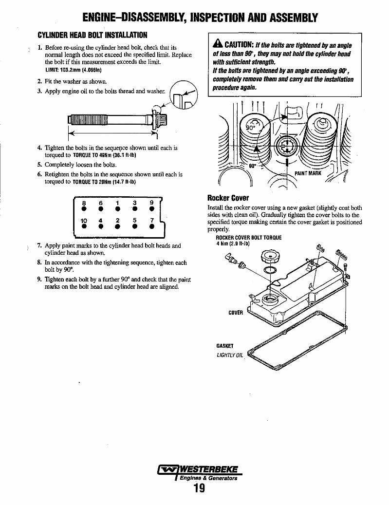
ENGINE-DISASSEMBLY, INSPECTION AND ASSEMBLY CYLINDER HEAD BOLT INSTALLATION 1. Before re-using the cylinder head bolt, check that its
normal length does not exceed the specified limit. Replace the bolt if this measurement exceeds the limit. LIMIT: 103.2mm (4.066in)
2. Fit the washer as shown. D 3. Apply engine oil to the bolts thread and washer. \l.JID}
[]WIIlIIIIIIWIIIIIIIIIIIWIIIIIIIIIWIIIIlllllllWllilllll ___ I~l J I ( »'
4. Tighten the bolts in the seque!Jce shown until each is torqued to TORQUE TO 49Nm (36.1 fI-lb)
5. Completely loosen the bolts.
6. Retighten the bolts in the sequence shown until each is torqued to TORQUE TO 20Nm (14.7 fI-lb)
86139 • • •• • 10 4 2 5 7 • • • • •
7. Apply paint marks to the cylinder head bolt heads and cylinder head as shown.
8. In accordance with the tightening sequence, tighten each bolt by 90°.
9. Tighten each bolt by a further 90" and check that the paint marks on the bolt head and cylinder head are aligned.
A CAUTION: If the bolts are tightened by an angle of less than 911', they may not hold the cylinder head with SlIfficient strength. If the bolts are tightened by an angle exceeding 911', completely remove them and carry out the installation procedure again.
/~ .~.---><::;:r....PAINTMARK ~
------,
Rocker Cover Install the rocker cover using a new gasket (slightly coat both sides with clean oil). Gradually tighten the cover bolts to the specified torque making certain the cover gasket is positioned properly.
ROCKER COVER BOLT TORQUE 4 Nm (2.9 fI·lb)
COVER
GASKET
LIGHTLY OIL
Engines & Generators
19
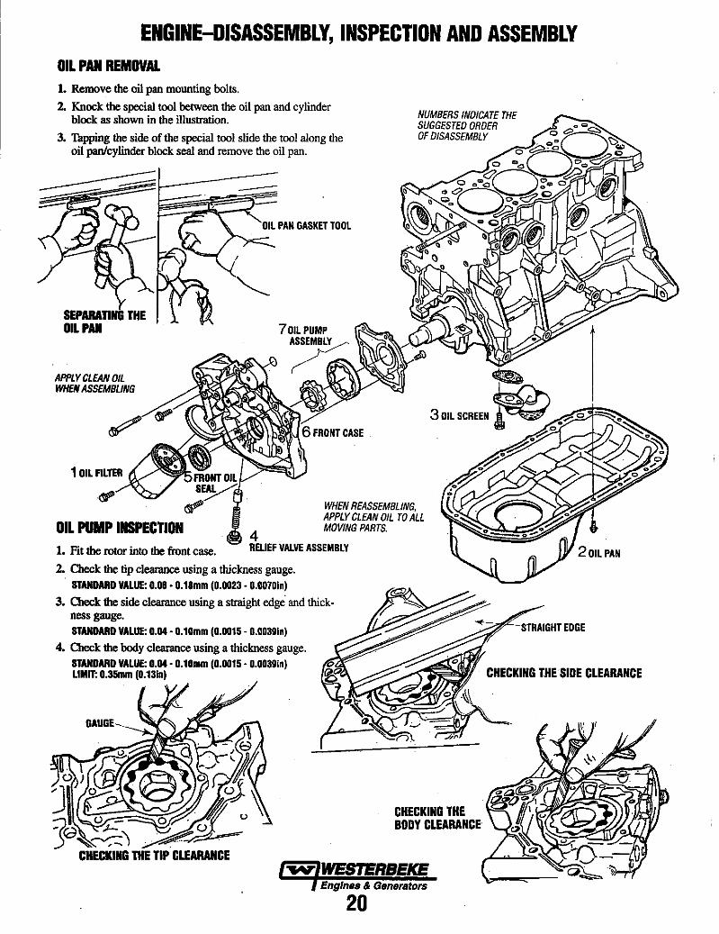
ENGINE-DISASSEMBLY, INSPECTION AND ASSEMBLY OIL PAN REMOVAL 1. Remove the oil pan mounting bolts.
2. Knock the special tool between the oil pan and cylinder block as shown in the illustration.
3. Thpping the side of the special tool slide the tool along the oil panlcylinder block seal and remove the oil pan.
SEPARATING THE fi OIL PAl
APPLY CLEAN OIL WHEN ASSEMBLING
FRONT Oil
.~ S~ ~
OIL PUMP INSPECTION 1. Fit the rotor into the front case.
4
Oil PAN GASKET TOOL
6 FRONT CASE .
WHEN REASSEMBLING, APPLY CLEAN OIL TO ALL MOVING PARTS.
RELIEF VALVE ASSEMBLY
2. Check the tip clearance using a thickness gauge. STANDARD VALUE: 0.06· 0.18mm (0.0023· 0.0070In)
3. Check the side clearance using a straight edge and thick· ness gauge. STANDARD VALUE: 0.04· 0,10mm (0.0015· 0,0039In) ~~~STRAlGiHT EDGE
4. Check the body clearance using a thickness gauge. STANDARD VALUE: 0,04· 0,10mm (0,0015· 0.0039in) LIMIT: O.35mm (0.13In)
CHECKING THE BODY CLEARANCE
...v: WESTERBEKE Englnee & Generators
20
CHECKING THE SIDE CLEARANCE

ENGINE-DISASSEMBLY, INSPECTION AND ASSEMBLY FRONT OIL SEAL CASE INSTALLATION
APPLY A 3MM BEAD OF F1P GASKET_ • . UJ'-"
FRONT OIL SEAL INSTALLATION
-SPECIAL TOOL
Apply engine oil to the 01 sea! lip, then push the oil· seal along the guide by hand until it touches the front case. Tap the oil seal into place using the special tool.
OIL PAN
OIL PAN INSTALLATION
APPLY A 4MM BEAD OF GASKET
Before insLalling the oil pan, inspect the oil pan drain hose and fittings for cracks and wear, replace if necessary.
Clean the mating surfaces of the cylinder block and oil pan. Apply a 4mm bead of fonn·in-place gasket to the outer circumference of the oil pan flange.
INSTALL A NEW OIL FILTER Screw the oil filter in until the sealing gasket contacts the front case, then tighten 3/4 turn.
SPIN·ON OIL FILTER.
SEALING GASKET APPLY CLEAN OIL WHEN ASSEMBLING
-..v- WESTERBEKE Engines & Generators
21
ENGINE-DISASSEMBLY, INSPECTION AND ASSEMBLY
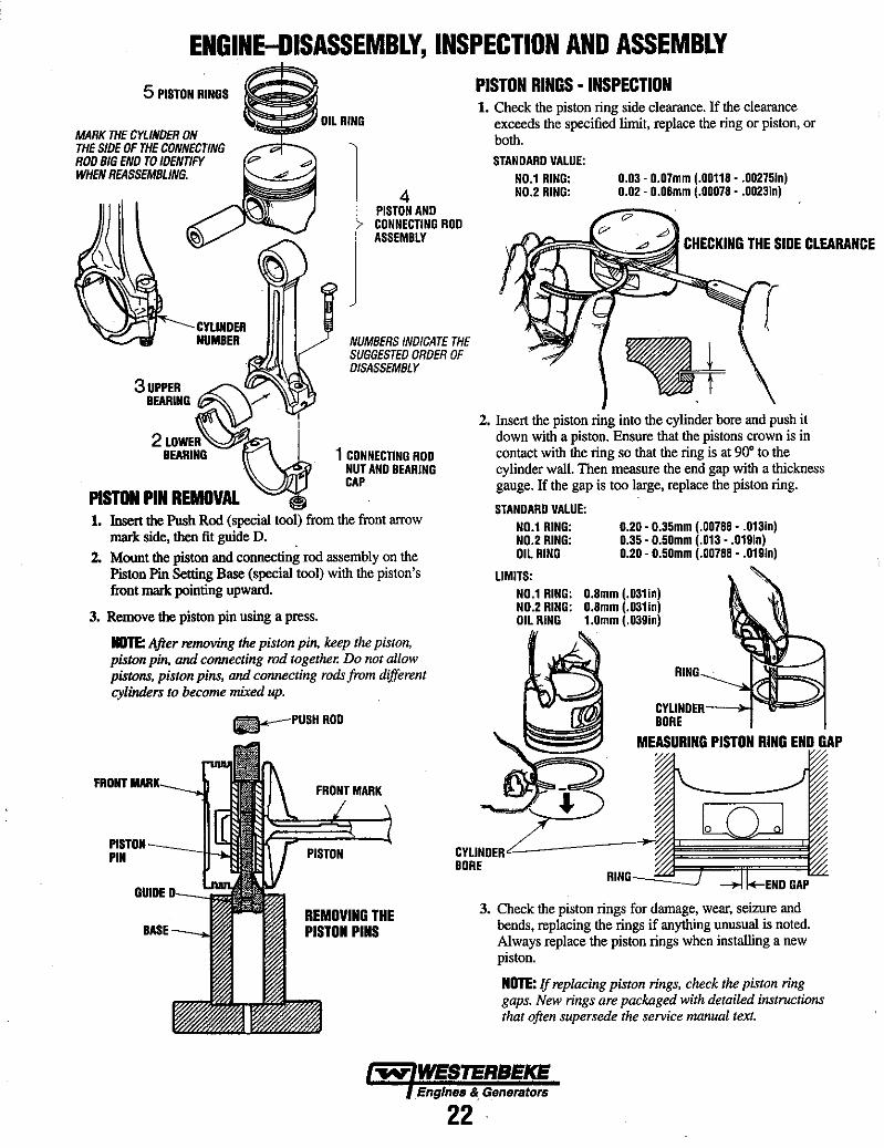
5 PISTON RINGS
MARK THE CYLINDER ON THE SIDE OF THE CONNECTING ROO BIG END TO IDENTIFY WHEN REASSEMBLING.
CYLINDER NUMBER
3UPPER ~ . BEARING~V
2LDWE~~' BEARING
PISTON PIN REMOVAL
OIL RING
1 4 PISTON AND CONNECTING ROD
J W~'"
NUMBERS INDICATE THE SUGGESTED ORDER OF DISASSEMBLY
1 CONNECTING ROD NUT AND BEARING CAP
1. Insert the Push Rod (special tool) from the front arrow mark side, then fit guide D.
2. Mount the piston and connecting rod assembly on the Piston Pin Setting Base (special tool) with the piston's front mark pointing upward.
3. Remove the piston pin using a press.
NOTE: After removing the piston pin, keep the piston, piston pin, and connecting rod together. Do not allow pistons, piston pins, and connecting rods from different cylinders to become mixed up.
a-PUSHROD
FRONT .... ,._~
PISTON RINGS· INSPECTION 1. Check the piston ring side clearance. If the clearance
exceeds the specified limit, replace the ring or piston, or both. STANDARD VALUE:
NO.1 RING: NO.2 RING:
0.03· 0.07mm (.00118 •. 00275In) 0.02' 0.06mm (.00078 •. 0023in)
CHECKING THE SIDE CLfARANCE
2. Insert the piston ring into the cylinder bore and push it down with a piston. Ensure that the pistons crown is in contact with the ring so that the ring is at 90" to the cylinder wall. Then measure the end gap with a thickness gauge. If the gap is too large, replace the piston ring.
STANDARD VALUE: NO.1 RING: NO.2 RING: OIL RING
LIMITS: NO.1 RING: NO.2 RING: OIL RING
0.20· 0.35mm (.00788 •• 013in) 0.35· 0.50mm (.013 •. 019In) 0.20· 0.50mm (.00788 •. 019In)
0.8mm (.031In) 0.8mm (.031In) 1.0mm (.039in)
RING
CYLINOER-_.r-~"'""~ BORE
MEASURING PISTON RING END GAP
PIN CYLINDERL----:::=J~~;~;~~~_ BORE
GAP
PISTON
GUIDE
REMOVING THE PISTON PINS
3. Check the piston rings for damage, wear, seizure and bends, replacing the rings if anything unusual is noted. Always replace the piston rings when installing a new piston.
NOTE: If replacing piston rings, check the piston ring gaps. New rings are packaged with detailed instructions that often supersede the service manual text.
~ WESTERBEKE Engines & Genefa/OfS
22
ENGINE-DISASSEMBLY, INSPECTION AND ASSEMBLY
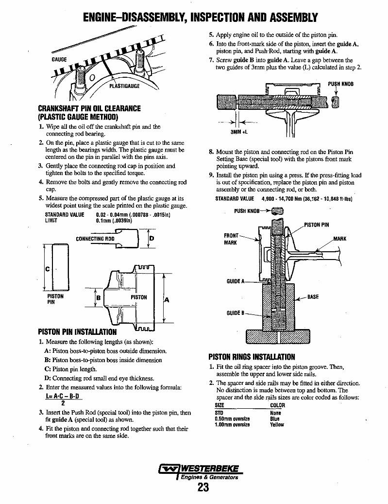
CRANKSHAFT PIN OIL CLEARANCE (PLASTIC GAUGE METHOD) 1. Wipe all the oil off the crankshaft pin and the
connecting rod bearing.
2. On the pin, place a plastic gauge that is cut to the same length as the bearings width. The plastic gauge must be centered on the pin in parallel with the pins axis.
3. Gently place the connecting rod cap in position and tighten the bolts to the specified torque.
4. Remove the bolts and gently remove the connecting rod cap.
S. Measure the compressed part of the plastic gauge at its widest point using the scale printed on the plastic gauge.
STANDARD VALUE 0.02 - 0.04mm (.000788 - .0015In) LIMIT O.lmm (.0039in)
c .
PISTON PIN
CONNECTING ROD: : } '1
PISTON PIN INSTALLATION 1. Measure the following lengths (as shown):
A
A: Piston boss-to-piston boss outside dimension.
B: Piston boss-to-piston boss inside dimension
C: Piston pin length.
D: Connecting rod small end eye tltickness.
2. Enter the measured values into the following formula:
l=A-C- B-D 2
3. Insert the Push Rod (special tool) into the piston pin, then fit gnide A (special tool) as shown.
4. Fit the piston and connecting rod together such that their front marks are on the same side.
S. Apply engine oil to the outside of the piston pin.
6. Into the front-mark side of the piston, insert the gnideA, piston pin, and Push'Rod, starting with gnideA.
7. Screw guide B into guide A. Leave a gap between the two guides of 3mm plus the value (L) calculated in step 2.
3MM+L
8. Mount the piston and connecting rod on the Piston Pin Setting Base (special tool) with the pistons front mark pointing upward.
9. Install the piston pin using a press. If the press-fitting load is out of specification, replace the piston pin and piston assembly or the connecting rod, or both.
STANDARD VALUE 4,900 -14,700 Nm (36,162 -10,848 "-lb.)
PUSHKN08~
PIN
MARK
GUIDE A---"
GUIDE 8
PISTON RINGS INSTALLATION 1. Fit the oil ring spacer into the piston groove. Then,
assemble the upper and lower side rails.
2. The spacer and side rails may be fitted in either direction. No distinction is made between top and bottom. The spacer and the side rails sizes are color coded as follows:
SIZE COLOR sm O.50mm oversize 1.00mm oversize
None 81ue Yellow
Engines & Generators
23
ENGINE-DISASSEMBLY, INSPECTION AND ASSEMBLY
~~i$SIDE RAIL
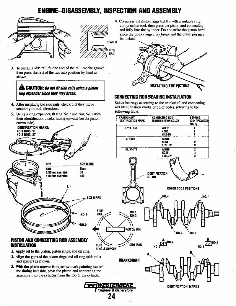
3. To install a side rail, fit one end of the rail into the groove then press the rest of the rail into position by hand as shown.
INSTAUING THE'PISTONS A CAUTION: Do not fit side rails using a piston ling sxpander since tIIey may break.
CONNECTING ROD BEARING INSTALLATION 4. After installing the side rails, check that they move
smoothly in both directions. 5. Using a ring expander, fit ring No.2 and ring No.1 with
their identification marks facing upward (on the piston
Select bearings according to the crankshaft and connecting rod identification marks or color codes, referring to the following table.
crown side). IDENTIFICATION MARKS: NO.1 RING: 1T NO.2 RING: 2T
CRANKSHAFT IDENTIFICATION MARK
I. YELLOW
II. NONE
III. WHITE
CONNECTING ROO IDENTIFICATION COLOR
BEARING IDENTIFICATION MARK
WHITE 1 NONE 1 YELLOW 2 WHITE 1 NONE 2 YELLOW 3 WHITE 2 NONE 3
L-__ ~~~ ________ ~YE=LL=cOW~\ ______ ~3~ __ ~ o SIZE sm O.50mm oversize 1.00mm oversize
1T
SIZE MARK None 50 100
""'~-NO.1
NO.2
SIDE RAIL~
II ... PISTON PIN
PISTON AND CONNECTING ROD ASSEMBLY INSTALLATION
~ /J NO.2 ~ '-;::::::>SIOE RAIL
1. Apply oil to the piston, piston rings, and oil ring. RING" SPACER
2. Align the gaps of the piston rings and oil ring (side rails and spacer) as shown.
3. With the piston crowns fron\ arrow mark pointing toward the timing belt side, press the piston and connecting rod assembly into the cylinder from the top of the cylinder.
CRANKSHAFT
~ WESTERBEKE Engines & Generators
24
10ENTtFICATION COLOR
COLOR CODE POSITIONS
A
NO.3 NO.2
B
NO.1
B 03NO.4
NO.3
IDENTIFICATION MARKS
ENGINE-DISASSEMBLY, INSPECTION AND ASSEMBLY
COLOR CODE POSITIONS (TYPE 1)
5
COLOR CODE POSITIONS (TYPE 2)
5---))~1 4
3
IDENTIFICA110N MARK POSITIONS
3
2 1
2
4
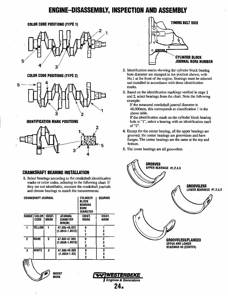
CRANKSHAFT BEARING INSTALLATION 1. Select bearings according to the crankshaft identification
marks or color codes. referring to the following chart. If they are not identifiable. measure the crankshaft journals and choose bearings to match the measurements.
CRANKSHAFT JOURNAL
RANGE COLOR IDENT. CODE MARK
YELLOW 1
2 NONE 2
3 WHITE 3
JOURNAL DIAMETER MM(IN)
47.995·48.000 (1.8910·1.8912)
47.985·47.995 (1.8906·1.8910)
47.980·48.985 (1.8904·1.93)
CYLINDER BEARING BLOCK BEARING BORE DIAMETER
IDENT. MARK
o 1 2 o 1 2 o 1 2
IDENT. MARK
1 2 3 2 3 4 3 4 5
o
TIMING BELT SIDE
CYLINDER BLOCK JOURNAL BORE NUMBER
2. Identification marks showing the cylinder block bearing bore diameter are SLamped in the position shown, with No.1 at the front of the engine. Bearings must be selected and installed in accordance with these identification marks.
3. Based on the identification markings verified in steps 1 and 2, select bearings from the chart. Note the following example:
If the measured crankshaft journal diameter is 48,OOOmm, this corresponds to classification 1 in the above table. If the identification mark on the cylinder block bearing hole is "1", select a bearing with an identification mark of "2",
4. Except for the center bearing, all the upper bearings are grooved. the center bearings are grooveless and have fianges. The center bearings are the same at the top and bottom.
5. The lower bearings are all grooveless.
GROOVELESS LOWER BEARINGS '1,2,4.5
GROOVELESS/FLANGED UPPER AND LOWER BEARINGS 13 (CENTER)
INDENT MARK -..v' WESTERBEKE
Engines & Genera/ors
24a
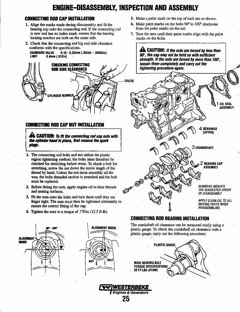
ENGINE-DISASSEMBLY, INSPECTION AND ASSEMBLY CONNECnNG ROD CAP INSTALLAnON 1. Align the marks made during disassembly and fit the
bearing cap onto the connecting rod. If the connecting rod is new and has no index mark, ensure that the bearing locking notches are both on the sarne side.
2. Check that the connecting rod big end side clearance conforms with the specifications. STANDARD VALUE 0.10· 0.25mm (.00394· .00985In) LIMIT 0.4mm (.015In)
CONNECTING ROD CAP NUT INSTALLATION
A CAUTION: Tom the CIInnecting IIId cap nuts with the cylinder heaJlln place, 11m 1'fH1I0ve the spade plugs.
1. The connecting rod bolts and nut utilize the plastic region tightening method. the bolts must therefore be checked for stretching before reuse. To check a bolt for stretching, screw the nut down the entire length of the thread by hand. Unless the nut turns smoothly all the way, the bolts threaded section is stretched and the bolt must be replaced.
2. Before fitting the nuts, apply engine oil to their threads and seating surfaces.
3. Fit the nuts onto the bolts and turn them until they are finger tight. The nuts must then be tightened alternately to ensure the correct fitting of the cap.
4. TIghten the nuts to a torque of 17Nm (12.5 ft-Ib).
!III" -11H1"
\
ALIGNMENT MARK
::=-- ~
'- \
NUT J BOLT II II
;::::=:---
S. Make a paint mark on the top of each nut as shown. 6. Make paint marks on the bolts 90· to 100· clockwise
from the paint marks on the nut. 7. Turn the nuts until their paint marks align with the paint
marks on the bolts.
A CAUTION: If the nuts are turned by less than 911', the cap may not be held on with sufficient strength. If the nuts are turned by more than 101f, loosen them completely and carry out the tightenIng procedure again.
1 OIL SEAL ASSEMBLY
4 BEARINGS (UPPER) ,
NUMBERS INDICATE THE SUGGESTED ORDER OF DISASSEMBLY
APPLY CLEAN OIL TO ALL . MOVING PARTS WHEN REASSEMBLING.
CONNECTING ROD BEARING INSTALLATION The crankshaft oil clearance can be measured easily using a plastic gauge. To check the crankshaft oil clearance with a plastic gauge, carry out the following procedul'll:
MAIN BEARING BOLT TORQUE SPECIFICATIONS 38 FHBS (51 NM)
~ WESTERBEKE Eng/nes & Generetors
25

ENGINE-DISASSEMBLY, INSPECTION AND ASSEMBLY
;o.....,~;::::-SCALE
PLASTIGAUGE
1. Wipe all oil off the crankshaft journal and the bearings inside surfaces.
2. Install the crankshaft. 3. Cut the plastic gauge such that its length matches the
width of the bearing, then place it on the journal along the journals axis.
4. Gently fit the crankshaft bearing cap and tighten the bolts to the specified torque.
S. Remove the bolts and gently remove the crankshaft bearing cap.
6. Using the scale printed on the plastic gauge bag, measure the plastic gauges crushed section at its widest point. STANDARD VALUE 0.02· 0.04mm (.000788· .00157In) LIMIT O.lmm (.00394In)
FILLET·ROLLED SECTION
NOTE: The crankshaft pins and journals are fillet-rolled and must not be machined to undersize dimensions.
CYLINDER BLOCK 1. Visually check for cracks, rust and corrosion and inspect
the cylinder block using a flaw detecting agent. Rectify defects where possible or replace the cylinder block.
2. Ensure that the top surface is free of gasket chips and other foreign material. Check the cylinder blocks top surface for distortion using a straight edge and thickness gauge. STANDARD VALUE 0.05mm (.00197;n) LIMIT O.lmm (.00394In)
MEASURE IN ALL OIRECTIONS
STRAIGHTEDGE
3. Check the cylinder walls for cracks and seizure marks. If defects are evident, bore all the cylinders to oversize or replace the cylinder block.
4. Using a cylinder gauge, measure each cylinders bore and cylindricity. If any cylinder is severely worn, bore all the cylinders to oversize and replace the piston and piston rings accordingly. Take measurements at the points shown. STANDARD VALUE: CYLINDER BORE 75.5mm (2.97In) CYLINDRICITY O.lmm or Ie .. (.00394In) MEASURE
CYLINDER GAUGE -..:==::::;~~
BORING CYLINDERS 1. Oversize pistons to be used should be determined on the
basis of the cylinder with the largest bore. 2. Oversize pistons are available with the following oversize
dimensions: 'O.25mm, O.5Omm, O.75mm and l.OOmm. Measure the diameter of the piston to be used. Boring must be carried out such that the piston-to-cylinder clearance complies with the standard value. The pistons diameter should be measured at the points shown.
3. Calculate the boring finish dimension based on the piston diameter dimension. BORING FINISH DIMENSIDN = PISTON O.D. + PISTDN-TO-CYLINDER CLEARANCE (0.02 - O.04mm (.000788 •• 00157In)) - HONING MARGIN (0.02MM)
4. Bore each cylinder to the calculated boring finish dimension.
A CAUTION: To prevent distortion caused by heat increased during boring, bore the cyllnden; in the following order: No.2, No.4, No.1 and No.3.
S. Hone the cylinders to the final finish dimension (piston 0.0. + piston-to-cylinder clearance).
6. Check the clearance between the pistons and cylinders. STANDARD VALUE 0.02 • 0.04mm (.000788 - .00157In)
~-::;.:~:=;;:;;;~=-'~ THRUST OIRECTION
~ WESTERBEKE PISTON D.D. Engines & Generators
26
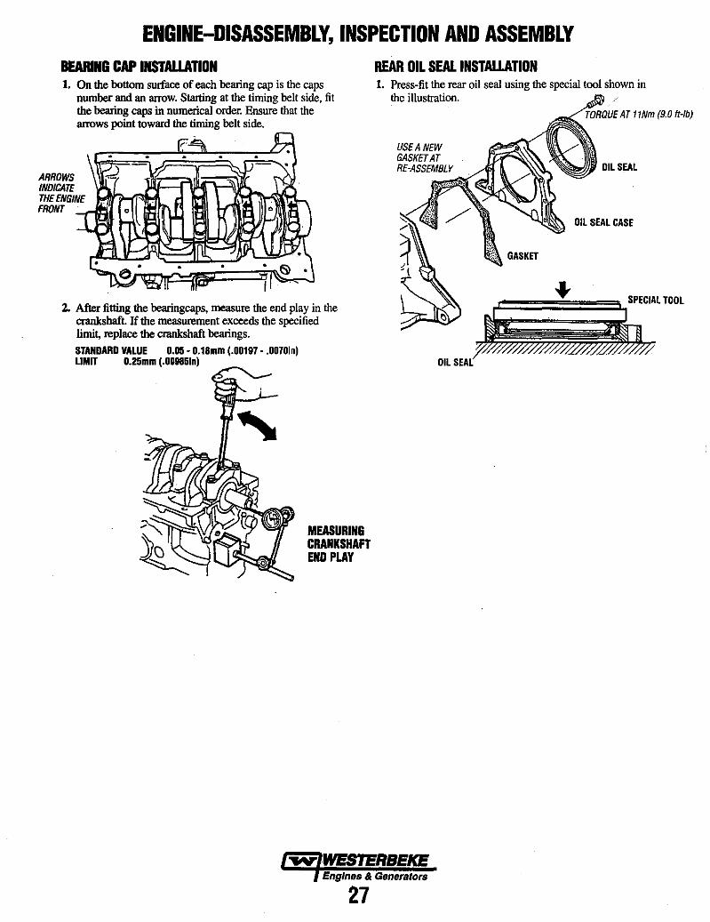
ENGINE-DISASSEMBLY, INSPECTION AND ASSEMBLY aWING CAP INSTALLATION 1. On the bottom surface of each bearing cap is the caps
number and an arrow. Starting at the timing belt side, fit the bearing caps in numerical order. Ensure that the arrows point toward the timing belt side.
ARROWS INOICATE THEENGINE FRONT
2. After fitting the bearingcaps, measure the end play in the crankshaft. If the measurement exceeds the specified limit, replace the crankshaft bearings. STANDARD VALUE 0.05 - 0.18mm (.00197 - .0070In) LIMIT 0.25mm (.00985In)
MEASURING CRANKSHAFT END PLAY
REAR OIL SEAL INSTALLATION 1. Press-fit the rear oil seal using the special tool shown in
the illustration. TORQUE AT 11Nm (9.0 It-Ibi
OIL SEAL
OIL SEAL CASE
r=======3.,SPECIAL TOOL
OIL SEAL
~WESTERBEKE EngInes & Generators
27
) ,
)
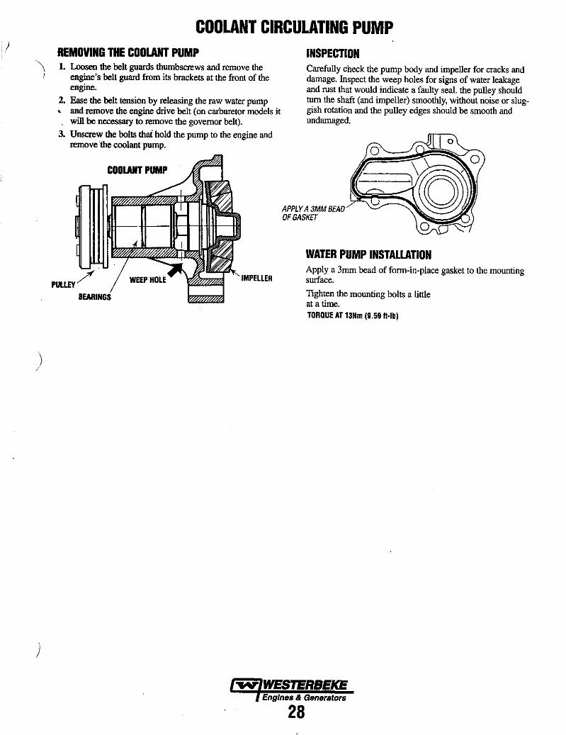
COOLANT CIRCULATING PUMP REMOVING THE COOLANT PUMP 1. Loosen the belt guards thumbscrews and remove the
engine's belt guard from its brackets at the front of the engine.
2. Ease the belt tension by releasing the raw water pump , and remove the engine drive belt (on carburetor models it , will be necessary to remove the governor belt).
3. Unscrew the bolts thai hold the pump to the engine and remove the coolant pump.
COOLANT PUMP
PULLEY? IMPELLER
INSPECTION Carefully check the pump body and impeller for cracks and damage. Inspect the weep holes for signs of water leakage and rust that would indicate a faulty seal. the pulley should turn the shaft (and impeller) smoothly, without noise or sluggish rotation and the pulley edges should be smooth and undamaged.
APPLY A 3MM BEAD DFGASKET
WATER PUMP INSTALLATION Apply a 3mm bead of form-in-place gasket to the mounting surface.
Tighten the mounting bolts a little at a time. TORQUE AT 13Nm (9,59 H·lb)
Engines & Generators
28

DISTRIBUTER CHECK THE DlSmlBUTER CAP FOR CRACKS. WEAR AND EVIDENCE OF ARCHING OR BlJRNING. IF ANY OF THESE CONDITIONS EXIST. REPLACE THE DlSmlBUTER CAP. .
3 COVER NUMBERS INDICATE THE SUGGESTED ORDER OF DISASSEMBLY
1 CAP
7_ ~~~. SINK ~.
• #~ • 8
~ ..... ~ fff BREAKER
•••... _ PLATE "" . . "'" 6
"" IGNITER
5 CONNECTOR .,
"''''
IGNITION COIL INSPECTION Use a tester to measure the pnmary and secondary coil resistance. Primary coil resistance between terminals 1 and 3. STANDARD VALUE 0.9 -1.211 a~
Secondary coil resistance between terminals 1 ~ 3 and secondary terminal. STANDARD VALUE 20 - 29kll
SECONDARY +j~~i1 TERMINAL
IGNITION COIL
PICK-UP ASSEMBLY Use a tester to measure pick-up coil resistance. STANDARD VALUE 420 - 540kll
Check that when a screwdriver is passed near the iron core of the pick -up assembly the needle of the tester deflects.
INSTALLATION OF PICK-UP ASSEMBLY Adjust the gap between the signal rotor and the pick-up assembly. STANDARD VALUE 0.05mm (.00197In) '5' g - 275,.." oIL ,010 "
SIGNAL
DISTRIBUTOR INSTALLATION 1. Tum the crankshaft clockwise until the No.1 cylinder is a
IDC on its compression stroke.
2. Align the alignment marks on the distributor housing and coupling.
3. Fit the distributor onto the engine. aligning the stud bolts with the slots in the distributor mounting flange.
ALIGNMENT MARK
INSPECTING SPARK PLUGS
ALIGNMENT MARK
Check the plugs for carbon build-up and burning. Check the plug gap. SPARK PLUG GAP 0.7 - 0.8mm (0.028 - 0.031In)
Engines & Generators
29

TESTING THE IGNITER DESCRIPTION Prepare the wiring as shown so electric current will flow in the ignition coil. Place the tip of a screwdriver close to the center of the pickup coil of the igniter to see if sparks occur. If sparks occur, the igniter is good.
A CAUTION: Never bring a magnet near the center of the pick·up coil. 00 not mix up the wire connections to tenninals Band C as that would damage the igniter. If the distributor Is operated with the extemal resister left shorted, the Igniter and coil will overheat.
+
I·BAITERY
~ WESTERBEKE Engines & Generators
30
IGNITER
GROUND ~ THE CASE
IGNITION COIL
3-WIRE GAP (10MM)
TESTING DIAGRAM

DC ELECTRICAL SYSTEM ALTERNATOR The charging system consists of a DC belt driven alternator with a voltage regulator, an engine DC wiring harness, a mounted DC circuit breaker and a battery with connecting cables. Because of the use of integrated circuits (Ie's), the electronic voltage regulator is very compact and is mounted internally or on the back of the alternator.
'14 BROWN TO TB2-4
'14 VIOlET
1. Start the engine. 2. After the engine has run for a few minutes, measure the
starting battery voltage at the battery tenninals using a multimeter set on DC volts. a. If the voltage is increasing toward 14 volts, the alterna
tor is working; omit Steps 3 through 8 and go directly to "Checking the Service Battery~' on the -next page.
b. If the voltage remains around 12 volts, a problem exists with either the alternator or the charging circuit; continue with Steps 3 through 8.
(gQJ MUlTIMETER~. --1'10
COM
TO FUEL SOLENOIO, LIFT PUMP ANO
. OISTRIBUTOR
AMP ALTERNATOR SEE WIRING DIAGRAM
..... ...."" _~" FOR WIRE CONNECTIONS.
GROUND
ALTERNATOR TROUBLESHOOTING
A WARNING: A failed alternator can become very hot. Do not touch until the alternator has cooled down.
Use this troubleshooting section to detennine if a problem exists with the charging circuit or with the alternator. If it is determined that the alternator or voltage regulator is faulty, have a qualified technician check it. The alternator charging circuit chaIges the starting battery and the service battery. An isolator with a diode, a solenoid or a battery selector switch is usually mounted in the circuit to isolate the batteries so the starting battery is not discharged along with the service battery. If the alternator is charging the starting battery but not the service battery, the problem is in the service battery's charging circuit and not with the alternator.
Testing the Alternator
A CAUTION: Before starting the engine make certain that tweryone Is clear of moving partsl Keep awa¥ from sheaves and belts during test procedures.
A WARNING: When testing with a multimeter: DC and AC circuits are often mixed together in marine applications. A/rIays disconnect a shore power cord, fsD/ate DC and AC convertelS, and shut doWn the engine befDte perftmnlng DC testing. No AC tests should be made without a proper knowledge of AC circuits.
TESTING THE STARTING BAmRY/ALTERNATOR (ENGINE RUNNING)
e
-=GROUND STARTING BATTERY
3. Turn off the engine. Inspect all wiring and connections. Ensure that the battery terminals and the engine ground connections are tight and clean.
A CAUTION: To avoid damage to the battery charging circuit, never shut off the engine battery switch when tlie engine is running!
4. If a battery selector switch is in the charging circuit, ensure that it is on the correct setting.
5. TUrn on the ignition switch, but do not start the engine. 6. Check the battery voltage. If the battery is in good condi
tion, the reading should be 12 to 13 volts.
TESTING THE ALTERNATOR VOLTAGE
~ o _ ... k---;,MUlTIMETER
(IGNITION ON • ENGINE OFF) ~l:;~:ii~
~b:::::::::::=S~l;ART;:ING BATTERY
Engines & Generators - GROUND
31
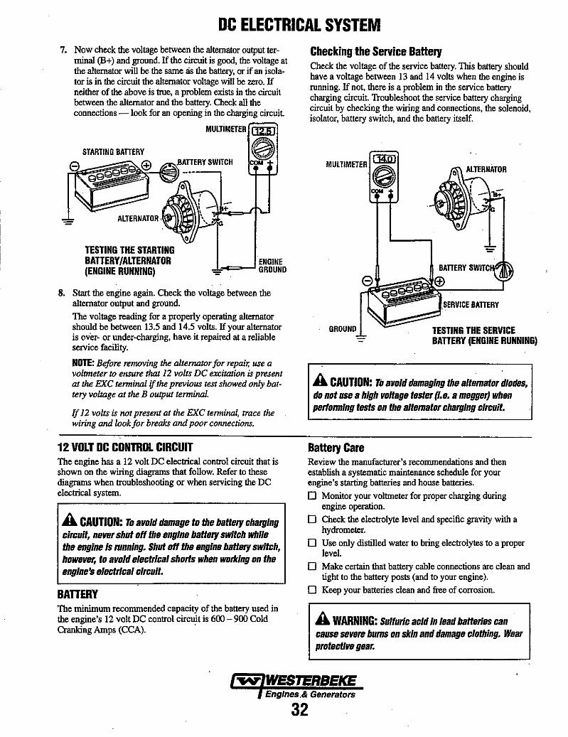
DC ELECTRICAL SYSTEM 7. Now check the voltage between the alternator output ter·
minaJ (B+) and ground. If the circuit is good, the voltage at the alternator will be the same lis the battery, or if an isola· tor is in the circuit the alternator voltage will be zero. If neither of the above is true, a problem exists in the circuit between the alternator and the battery. Check all the connections -look for an opening in the charging circuit
STARTING BATIERY
g9 (±) g99Q .
TESTING THE STARTING BATTERY/ALTERNATOR (ENGINE RUNNING)
MUlTIMETER (]2JD
G OM
'.,..c:=--' ENGINE ~ GROUND
8. Start the engine again. Check the voltage between the alternator output and ground. The voltage reading for a properly operating alternator should be between 13.5 and 14.5 volts. If your alternator is over- or under-charging, have it repaired at a reliable service facility.
NOTE: Before re1lWving the alternator for repair, use a voltmeter to ensure that 12 volts De excitation is present at the EKe tenninal if the previous test showed only battery voltage at the B output tenninal.
If 12 volts is not present at the Exe tenninal, trace the wiring and look for breaks and poor connections.
12 VOLT DC CONmOL CIRCUIT The engine has a 12 volt DC eleclrical control circuit that is shown on the wiring diagrams that follow. Refer to these diagrams when troubleshooting or when servicing the DC eleclricaJ system.
A CAUTION: To avoid damage to the battery charging circuit, never shut off the engine battery switch while ths snglne Is mnnlng. Shut off the engine battery switch, howsver, to avoid IIllIctrlcal shorts when working on the IInglne's slsctrlcal circuit.
BATTERY The minimum recommended capacity of the battery used in the engine's 12 volt DC control circuit is 600 - 900 Cold Cranking Amps (CCA). '
Checking the Service Battery Check the voltage of the service battery. 1bis battery should have a voltage between 13 and 14 volts when the engine is running. If not, there is a problem in the service battery charging circuit. Troubleshoot the service battery charging circuit by checking the wiring and connections, the solenoid, isolator, battery switch, and the battery itself.
MULTIMETEB I COM
GROUND
,SERVICE BATIERY
TESTING THE SERVICE BATTERY (ENGINE RUNNING)
A CAUTION: To avoid damaging the altemator diodes, do not use a high voltage tester (I.s. a mllggsr) when pedonnlng tests on ths alternator charging circuit.
Battery Care Review the manufacturer's recommendations and then establish a systematic maintenance schedule for your engine's starting batteries and house batteries. o Monitor your voltmeter for proper charging during
engine operation. o Check the electrolyte level and specific gravity with a
hydrometer. o Use only distilled water to bring electrolytes to a proper
level. o Make certain that battery cable connections are clean and
tight to the battery posts (and to your engine). o Keep your batteries clean and free of corrosion.
A WARNING: Sulfuric acid In lead batteries can cause sevllre bums on skin and damagll clothing. Wear protective gear.
Englnes,& Generators
32
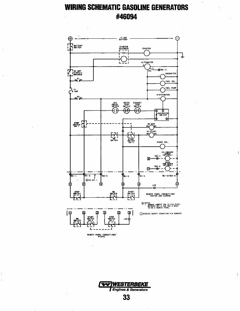
WIRING SCHEMATIC GASOLINE GENERATORS #46094
(~ 12 VOC -BATTERY
r~ IATiUY STARTER I ISw,fCH + SOLENOIO STARTER r--,
: : ~ L __ l .I.L HANATOR ,
:; ~,20 AIIP
, EXC----0TBI - 5
I( ICIRCUIT HOURIIETER ..... I-'IIIIUII[I
~" run SOL
" rA'If' run PUM'
01 STR 18UTOR
~1I~n
." WUER EXHAUST "EIS. lEN' TENP SWITCII
~ :Q\ , '<.Y IOV[RSP[[
SWITCH
STOP r I"} ____ ------ --. 1I:2'R~5 SWITCH I U1 I .... I-'
, , r !:oJ
KI-STAn r;;'J .. " L_J L_J •• START SWITCH SWITCH
nT r CHon SOL.
Oll.[m:un IOPTlOilAlI
T82-1 0-[!1--0-- -
WAnl I n ... uou I lB2-l! IOPTI0II4L1
~ ._ .. ..., .. _ .. - ~-o-- -.. _- .. __ .. t-- .. _ .. _ .. _.
11-' BI'Z ~.! 1IZ-3 BI-5 T81-. T81-611112-5)
<!lIlt IDrl ,-
• • iI • '" • " .. ~I~~
L'-J
•• ~~lCK -, L~J
REMOTE PAlin CONNECT/OIlS' "3112
START SWITCH r-, L~J
REIIOTt 'AIIEt CONNECTIONS 135106 10110 usnl
0~~lU~VE JUMP(A IO~ I~ PIli PLUG} 8(Tt'HH T81-~ AND 181-3 WHEN USUG A UMOH PAHEl.
OOUroU5 UWOl{ COWNECTOR PIM NUMIIUS
Engines & Generators
33

, ,
WIRING DIAGRAM GASOLINE GENERATORS #46094
. ~,
UAJ!J<
"" " tlJlil
~~ ~
~
.... li~l~~~11 Q
AI ToSN Tns ". •
~~ y'
~ ~ ~ ; l ,
)-i ~ i ~ =
i-Iii I[OI~T
QJJ. (1:0' ~ QISTRle!'TOB ~
V I IE T f:!I"'~ llifuJll r- 0 $..4
I!~
8ATT[Rf~ SWlftli LY
, , ~2 ! ! ,I >V''-l ~ ,.~
(~ >.IUlli!
,~ ... '"
, , 12 VDC
, Lq :
• GIOUO
~ E $.f.!I.%f. , i ;
~=I t- '" ""." ~ , .. - .. _ .. _ ..
r- r- ... -"-,,-,,- - .. -
! ~ ! !
5' ~ =-:-::
...... t = , : .. ,
~ l '" b"'" ' '-!
~=nl :::M~t:I"l~E~~ ~T ... A.'NGI UtU, UTU. Uili. 182 11
lIJ"
• '" ·5 '"'4 '"'J I , , TIl-J
III • . lBl-'
{i) to L. TI'"
(j) G>t"'-"L--8 In-'
000 sao
~ . ~ ~
V [I: ~I
il
" .. " " .. , '" "" ...
'" "'-
'" b'"''
~ ,
H.I I" "" ..
I Ir)~ I" 'n';;' ';; I
OVERSPE!!I) ClRCUT
'"
" ~.
: ".
""" WESTERBEKE Engines & Generators
34
~ - - - :-M;;'''': 'Q;"; , , I I ·IIR£ I L_~ __ J r------l I ~ ~"OIAl I , , , L_= __ '
I-- . _ .. _ .. - .. _ ..
~
'" ",
r::JlJ ~ ~; '"
os-~~I
~
~ =
/
.,...,.. FUSE , ANI' •
h c I STAAT I ISTOP &WITCH
;;;-;
L ~ • ON
."''' -'" .. , HOUl
I' -
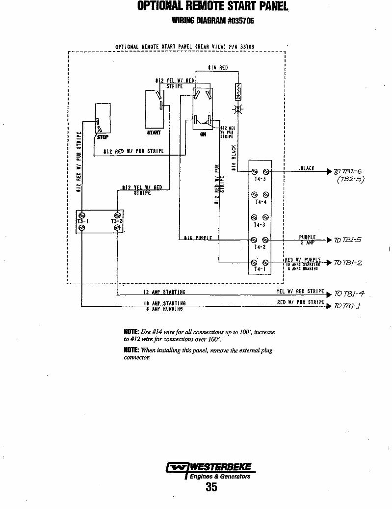
OPTIONAL REMOTE START PANEL. WIRING DIAGRAM #035706
OPTIOMAl REMOTE START PANEL (REAR VIEW) PIN 33103 r----------------------------------------------------- , I I I I
: m RED : I , I
.--... ... -~
>-'" ~ :> ... -,. Q ... ~
~ -.. ~
13-1 ~
.l2 HI WI RFD STRIPE
V)~ 'I .-- [f-
~ ~ ..
ITART ON
112 RED WI PUR STRIPE
II? YFI WI RED STRIPE
I 13-2 , ~.
., .. " .. ,.
J ~ ~ I-
IZ lUI i/ rut STIIPE
'" u < ~ ., ,
~ ~ ,
~ .. ~~ ,
...,,"" _w H-S , .... ,
e. ~ , ,
~ ~ §§ ,
N ,
:; 14-4 ,
§§ 14-3
""""' 14-2'
.BlACK •
PURPLE II-< AMr
"". "" RED WI PURPl~ 14-1 i ': ::fl ;ml;:'
-- ------_. , , ,
-~-------------------------------~-------~ 12 AMP STARTING
19 AMP ·STARTING , AMP RUHIiTNG
NOTE: Use #14 wire for all connections up to 100', increase to #12 wire for connections over 100'.
NOTE: When installing this panel, remove the external plug connector.
Engines & Generators
35
YEl WI RED STRIPE .. --,. RED WI PUR STRIPE .. -.
707B1-6 -(782-5)
7lJ TBl-5
TOTB/-2
]V TBI-4-
TOTBl-1
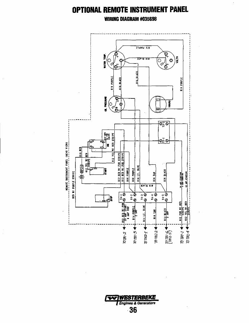
OPTIONAL REMOTE INSTRUMENT PANEL WIRING DIAGRAM #035698
K '''''' II. ~i~o ~ 1 ~ "'" II. ~ :0 ~ -;-----.:;:..--
~ -L' _+-__ ,
.-_-41~-+~~~~~+-~ ~
~ WESTERBEKE Engines & Genera/Drs
36
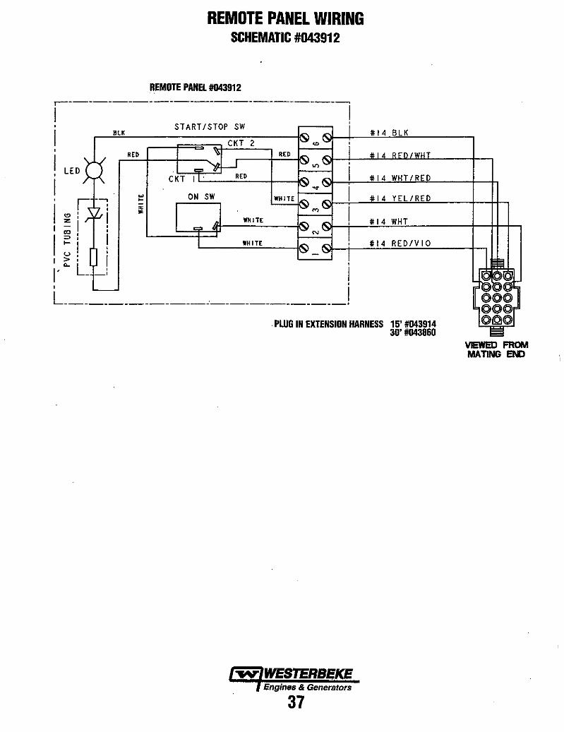
REMOTE PANEL WIRING SCHEMATIC #043912
REMOTE PANEl #043912 ,------------------------------
/ ! i START/STOP SW
,
I ,
I ,
I '" , I = 1
I CD , =>,
1-1 u, >, 0..
/' ,
RED RED
C KT I L----="---t-~
ON SW
WHITE
WHITE
. PLUG IN EXTENSION HARNESS 15' #043914 30'#043860
VIEWED FROM MATING Ell[)
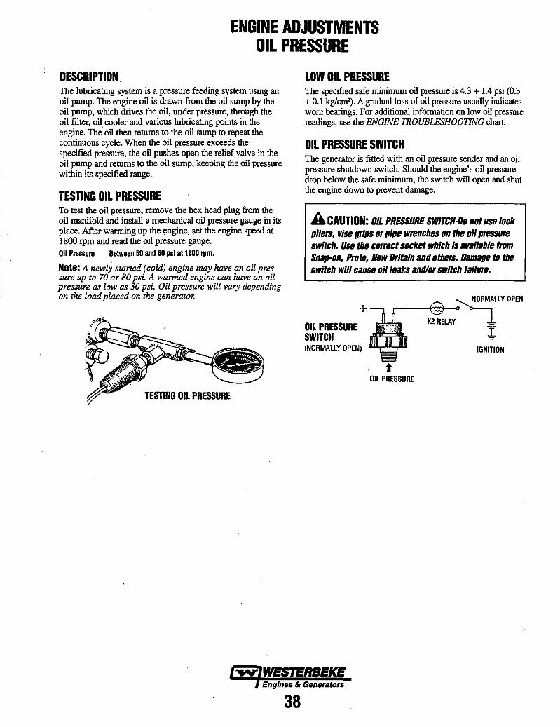
ENGINE ADJUSTMENTS OIL PRESSURE
DESCRIPTION The lubricating system is a pressure feeding system using an oil pump. The engine oil is drawn from the oil sump by the oil pump, which drives the oil, under pressure, through the oil filter, oil cooler and various lubricating points in the engine. The oil then returns to the oil sump to repeat the continuous cycle. When the oil pressure exceeds the specified pressure, the oil pushes open the relief valve in the oil pump and returns to the oil sump, keeping the oil pressure within its specified range.
TESTING OIL PRESSURE To test the oil pressure, remove the hex head plug from the oil manifold and install a mechanical oil pressure gauge in its place. After warming up the ~ngine, set the engine speed at 1800 rpm and read the oil pressure gauge. 011 P .... ure Between 50 and 60 psi at 1800 rpm.
Note: A newly started (cold) engine may have an oil pressure up to 70 or 80 psi. A warmed engine can have an oil pressure as low as 30 psi. Oil pressure will vary depending on the load placed on the generator.
TESTING OIL PRESSURE
LOW OIL PRESSURE The specified safe minimum oil pressure is 4.3 + 1.4 psi (0.3 + 0.1 kg/em'). A gradual loss of oil pressure usually indicates worn bearings. For additional information on low oil pressure readings, see the ENGINE TROUBLESHOOTING chart.
OIL PRESSURE SWITCH The generator is fitted with an oil pressure sender and an oil pressure shutdown switch. Should the engine's oil pressure drop below the safe minimum, the switch will open and shut the engine down to prevent damage.
A CAUTION: OIL PRESSURE SWlrCH-Da nat use lack pliers, vise grips or pipe wrenches an the ail pressure switch. Use the correct sacket which is available tram Snap-an, Prato, New Britain and others. Damage to the switch will cause ail leaks and/or switch failure.
+
OIL PRESSURE SWITCH (NORMAllY OPEN)
r-__ ~~.<J~ALlY OPEN
K2RELAY 1 ~
IGNITION
Oil PRESSURE
-.v WESTERBEKE Engines & Generators
38
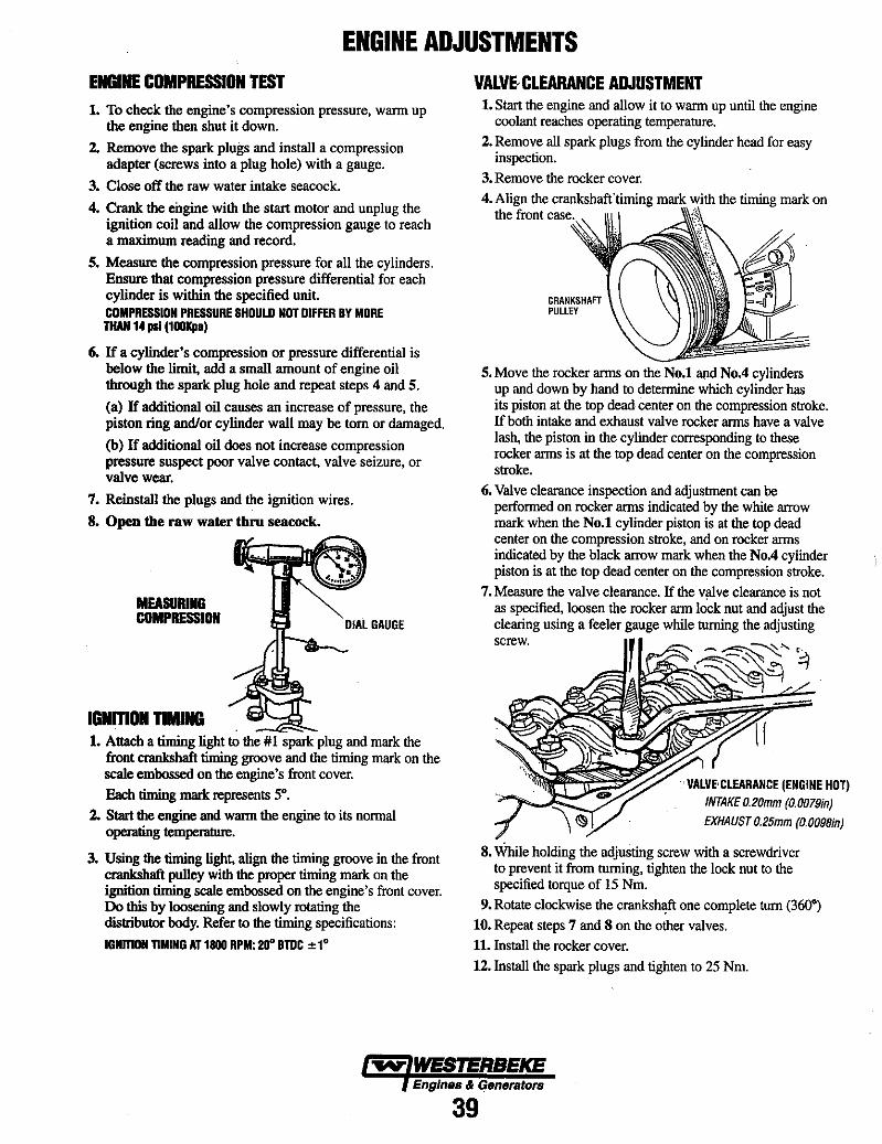
ENGINE ADJUSTMENTS ENGINE COMPRESSION TEST 1. To check the engine's compression pressure, wann up
the engine then shut it down.
2. Remove the spark plugs and install a compression adapter (screws into a plug hole) with a gauge.
3. Close off the raw water intake seacock.
4. Crank the engine with the start motor and unplug the ignition coil and allow the compression gauge to reach a maximum reading and record.
5. Measure the compression pressure for all the cylinders. Ensure that compression pressure differential for each cylinder is within the specified unit. COMPRESSION PRESSURE SHOULD NOT DIFFER BY MORE TIfAH 14 psi (100Kpa)
6. If a cylinder's compression or pressure differential is below the limit, add a small amount of engine oil through the spark plug hole and repeat steps 4 and 5.
(a) If additional oil causes an increase of pressure, the piston ring and/or cylinder wall may be tom or damaged.
(b) If additional oil does not increase compression pressure suspect poor valve contact, valve seizure, or valve wear.
7. Reinstall the plugs and the ignition wires.
8. Open the raw water thru seacock.
MEASURING COMPRESSION
IGNmON DMING . .
DIAL GAUGE
1. Attach a timing light to the #1 spark plug and mark the front crankshaft timing groove and the timing mark on the scale embossed on the engine's front cover. Each timing mark represents 5·.
2. Start the engine and wann the engine to its normal operating temperature.
3. Using the timing light, align the timing groove in the front crankshaft pulley with the proper timing mark on the ignition timing scale embossed on the engine's front cover. Do this by loosening and slowly rotating the distributor body. Refer to the timing specifications:
IGNmON nMING AT 1800 RPM: 211" BTOC ± 1·
VALVE, CLEARANCE ADJUSTMENT 1. Start the engine and allow it to wann up until the engine
coolant reaches operating temperature. 2. Remove all spark plugs from the cylinder head for easy
inspection. 3. Remove the rocker cover. 4. Align the crankshaft·timing mark with the timing mark on
the front
CRANKSHAFT PULLEY
5. Move the rocker arms on the No.1 and No.4 cylinders up and down by hand to detennine which cylinder has its piston at the top dead center on the compression stroke. If both intake and exhaust valve rocker arms have a valve lash, the piston in the cylinder corresponding to these rocker arms is at the top dead center on the compression stroke.
6. Valve clearance inspection and adjustment can be performed on rocker arms indicated by the white arrow mark when the No.1 cylinder piston is at the top dead center on the compression stroke, and on rocker anns indicated by the black arrow mark when the No.4 cylinder piston is at the top dead center on the compression stroke.
7. Measure the valve clearance. If the valve clearance is not as specified, loosen the rocker ann lock nut and adjust the cleating using a feeler gauge while turning the adjusting screw.
~''=9
VALVE' CLEARANCE (ENGINE HOT) INTAKE 0.20mm (0.0079;n)
EXHAUST 0.25mm (0.0098;n)
8. While holding the adjusting screw with a screwdriver to prevent it from turning, tighten the lock nut to the specified torque of 15 Nm.
9. Rotate clockwise the cranksh'!fi one complete turn (360·) 10. Repeat steps 7 and 8 on the other valves. 11. Install the rocker cover. 12. Install the spark plugs and tighten to 25 Nm.
~ WESTERBEKE EnglneB & Generators
39

ENGINE ADJUSTMENTS
SPARK PLUGS The spark plugs should be cleaned and regapped after the first 50 hour break-in period, then inspected every 250 hours thereafter and replaced as needed.
A WARNING: Do not remove the spark plugs while the engine is hot. Allow the engine to cool before removing them.
SPARK PLUG GAP: 0.031 ± 0.002 In. (0.8 - 0.05 mm).
SPARK PLUG TORQUE: 25 Nm. (18.45 «-Ih)
NOTE: Loctite Anti-Seize applied to the threaded portion of the spark plugs will retard corrosion, making Juture removal of the spark plugs easier.
INSPECT FOR DAMAGE - ...... ,.--"
CHECK FOR oET.ERI(IRA1·loN~
INSPECTING THE SPARK PLUGS
i -====;= GAP
HIGH TENSION CORDS (IGNITION WIRES)
Check the ignition wires every 500 operating hours as engine compartment heat can deteriorate the wires.
Check the resistance of each wire. Do not pull on the wire because the wire connection inside the cap may become separated or the insulator may be damaged. When removing the wires from the spark plugs, grasp and twist the molded cap, then pull the cap off the spark plug.
The resistance value is 410 ohm per inch of wire.
CHECKING RESISTANCE
DRIVE BELT ADJUSTMENT The drive belts must be properly tensioned. Excessive drive belt tension can cause rapid wear of the belts and reduce the service life of the fresh water pump's bearing A slack belt or the presence of oil on the belt can cause belt slipping, resulting in high operating temperatures. This generator has two drive belts, one drives the governor and alternator and the other drives the raw water pump. The tension adjustment procedure for both belts is as follows:
1. Remove the belt guard.
2. To adjust the governor/alternator drive, loosen the two governor mounting bolts.
To adjust the raw water pump/fresh water pump drive belt, loosen the two raw water pump mounting bolts.
3. With the bell(s) loose, inspect for wear, cracks and frayed edges and replace if necessary.
4. To loosen or tighten the alternator drive belt, slide the alternator in or out as required, then retighten its mounting bolts.
To loosen or tighten the raw water pump/fresh water pump drive belt, slide the raw water pump in or out as required, then retighten its mounting bolts.
5. The drive belts are properly adjusted if it can be deflected no less than 3/8 inch (lOmm) and no more than 112 inch (12mm) as the belt is depressed with the thumb at the midpoint between the two pulleys on the longest span of the belt.
A WARNING: Never attempt to check Dr adjust a drive belt's tension while the engine is in operation.
6. Operate the engine for about 5 minutes, then shut down the engine and recheck the belts tension.
7. Replace the belt guard.
Engines· & Generators
40
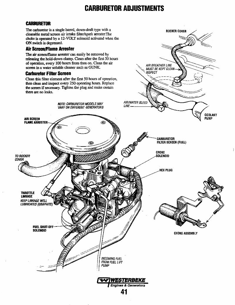
CARBURETOR ADJUSTMENTS
CARBURETOR The carburetor is a single barrel, down-draft type with a cleanable metal'screen air intake 6lterlspark arrester.The choke is operated by a 12-VOLT solenoid activated when the ON switch is depressed.
Air ScreenJFlame Arrester The air screenlflame arrester can easily be removed by releasing the hold-down clamp. Clean after the first 50 hours of operation, every 100 hours from then on. Clean the air screen in a water soluble cleaner such as GUNK.
Carburetor Filter Screen Clean this 6lter element after the first 50 hours of operation, then clean and inspect every 250 operating hours. Replace the screen if necessary. Tighten the plug and make certain there are no leaks.
AIR st:REEN
NOTE: CARBURETOR MODELS MAY VARY ON DIFFERENT GENERATORS
AIRIWATER BLEED LlNE------l~~
. CARBURETOR
THROmE LINKAGE KEEP LINKAGE WELL LUBRICATED (GRAPHITE)
FUEL SHu:r-OFIF-~<2'-<~
INCOMING FUEL FROM FUEL LIFT PUMP
-.v WESTERBEKE Engines & Generators
41
FILTER SCREEN (FUEL)
CHOKE
PLUG
CHOKE ASSEMBLY
COOLANT PUMP
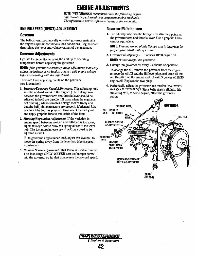
ENGINE ADJUSTMENTS NOTE: WESTERBEKE recommends that the following engine adjustments be perfonned by a competent engine mechanic. The information below is provided to assist the mechanic.
ENGINE SPEED (HERTZ) ADJUSTMENT
Governor Governor Maintenance 1. Periodically lubricate the linkage arm attaching points at
the governor arm and throttle lever. Use a graphite lubricant or equivalent. The belt-driven, mechanically operated governor maintains
the engine's rpm under various load conditions. Engine speed determines the hertz and voltage output of the generator. NOTE: Free movement of this linkage arm is imponant for
proper governorlthrottle operation. Governor Adjustments Operate the generator to bring the unit up to operating temperature before adjusting the governor.
NOTE: If the governor is severely out of adjustment, manually adjust the linkage at no-load to obtain a safe output voltage before proceeding with the adjustment.
There are three adjusting points on the governor (see illustration). .
1. Increase!Decrease Speed A4justment. This adjusting bolt sets the no-load speed of the engine. (The linkage arm between the governor arm and throttle lever should be adjusted to hold the throttle full open when the engine is not running.) Make sure this linkage moves freely and that the ball joint connectors are properly lubricated. Use graphite lube for this purpose. Disconnect the ball joint and apply graphite lube to the inside of the joint.
2. HunJinglReguloJion Adjustment. If the variation in engine speed between no-load and full-load is too great, adjust this eye bolt to draw the spring closer to the lever hub. The increase/decrease speed bolt may need to be adjusted as well.
If the governor surges under load, adjust this eye bolt to move the spring away from the lever hub (check speed adjustment).
3. Bumper Screw Adjustment. This screw is used to remove a no-load surge ONLY..NEVER turn the bumper screw into the governor so far that it increases the no-load speed.
2. Governor oil capacity - 3 ounces 10/30 engine oil.
NOTE: Do not ovelfill the governor.
3. Change the governor oil every 250 hours of operation.
To change the oil, remove the governor from the engine, remove the oil fill and the fill level plug, and drain all the oil. Reinstall on the engine and fill with 3 ounces of 10/30 engine oil. Replace the two plugs.
4. Periodically adjust the governor belt tension (see DRIVE BELTS ADJUSTMENT). Since belts stretch slightly, this stretching will, to some degree, affect the govenor's action.
LINKAGE ARM KEEP LINKAGE WELL LUBRICATED
SPEED
(UNDER)
FILL
~ WESTERBEKE Engines & Generators
42

WESTERBEKE 51 A MANDO ALTERNATOR DISASSEMBLY AND TESTING
FAN
HOUSING
EXCITER TERMINAL
SENSING TERMINAL
GROUND TERMINALE
TESTING THE OUTPUT CIRCUIT
REAR HOUSING
p
Y-j'iRMlliALB
1. Connect the positive voltmeter lead to the output terminal B and connect the negative lead to the ground terminal E on the alternator.
2. Wiggle the engine wiring harness while observing the voltmeter. The meter should indicate the approximate battery voltage, and should not vary. If no reading is obtained, or if the reading varies, check the alternator output circuit for loose or dirty connections or damaged wiring.
NOTE: Prior to any alterno.tor testing, illSpect the entire alterno.tor system wiring for defects. Check all cont!ectiollS for tightness and cleanliness, panicularly battery cable clamps and battery terminals. IllSpectthe alternator drive belt for excessive wear and replace if necessary. Also adjust for proper belttellSion.
A WARNING: A failed alternator can become very hot. Do not touch until the alternator has cooled down.
A WARNING Before starting the engine, make certain that everyone is clear of moving parts! Keep away from sheaves and belts during test procedures.
A WARNING Multimeters and DC Circuits DC and AC circuits are otter mixed together in marine applications. Always disconnect shore power cords, isolate DC and AC converters and shut down generators before performing DC testing. No AC tests should be made without proper knowledge of AC circuits.
REFER TO THE WIRING DIAGRAMS FOR THE ABOVE WIRING HARNESS CONNECTIONS
TESTING THE EXCITATION CIRCUIT 1. Connect the positive (+)'voltmeter lead to the excitation
terminal R on the alternator and the negative (-) lead to the ground terminal E on the alternator.
2. Turn the ignition switch to the on position and note the voltmeter reading. The reading should be 1.3 to 2.5 volts (see illustration).
3. If the reading is between .75 and 1.1 volts, the rotor field circuit probably is shorted or grounded. Disassemble the alternator and test the rotor as described under CLEAN AND TEST ALTERNATOR COMPONENTS in this section.
4. If the reading is between 6.0 and 7.0 volts, the rotor field circuit probably is open. Remove the regulator and inspect it for worn brushes or dirty slip rings. Replace the brushes if they are less than I14in. (6 mm) long. If the brushes and slip rings are in good condition, disassemble the alternator and test the rotor, as outlined under CLEAN AND TEST ALTERNATOR COMPONENTS in this section.
Engines & Generators
43
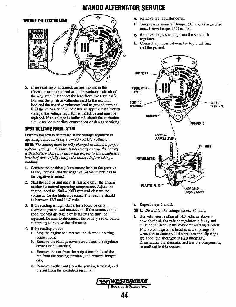
MANDO ALTERNATOR SERVICE
TESTING THE EXCITER LEAD
5. If no reading is obtained, an open exists in the alternator-excitation lead or in the excitation circuit of the regulator. Disconnect the lead from exc terminal R. Connect the positive voltmeter lead to the excitation lead and the negative voltmeter lead to ground terminal E. If the voltmeter now indicates an approximate. battery voltage, the voltage regulator is defective and must be replaced. If no voltage is indicated, check the excitation circuit for loose or dirty connections or damaged wiring.
TEST VOLTAGE REGULATOR Perform this test to determine if the voltage regulator is operating correctly, using a 0 - 20 volt DC voltmeter.
NOTE: The battery niust be fully charged to obtain a proper voltage reading in this tesl. lfnecessary, charge Ihe bal/ery wilh a battery chargeror allow lhe engine 10 run a sufficient lenglh of lime 10 fully charge the battery before laking a reading.
1. Connect the positive (+) voltmeter lead to the positive battery terminal and the negative (-) voltmeter lead to the negative terminal.
2. Start the engine and run it at fast idle until the engine reaches its normal operating temperature. Adjust the engine speed to 1500 - 2000 rpm and observe the voltmeter for the highest reading. The reading should be between 13.7 and 14.7 volts.
3. If the reading is high, check for a loose or dirty alternator ground lead connection. If the connection is good, the voltage regulator is faulty and must be replaced. Be sure to disconnect the battery cables before attempting to remove the alternator.
4. If the reading is low: a. Stop the engine and remove the alternator wiring
connections. b. Remove the Phillips cover screw from the regulator
cover (see illustration).
c. Remove the nut from the output terminal and the nut from the sensing terminal, and remove Jumper (A).
d. Remove another nut from the sensing terminal, and the nut from the excitation terminal.
e. Remove the regulator cover.
f. Temporarily re-install Jumper (A) and all associated nuts. Leave Jumper (B) installed.
g. Remove the plastic plug from the side of the regulator.
h. Connect a jumper between the top brush lead and the ground.
JUMPER A ----L;,L;~~;:~
REGULATOR --Il...J.. COVER
SENSING TERMINAL
T-__ OUTPUT
GROUND
REGUlATOR
\ \ \ \ \
CONNECT .. JUMPER WIRE \
\ I
PLASTIC PLUG
i. Repeat steps 1 and 2.
~U~IPER B
LEAD FROM BRUSH
NOTE: Do not let Ihe voltage exceed 16 volts.
TERMINAL
j. If a voltmeter reading of 14.5 volts or above is now obtained, the voltage regulator is faulty and must be replaced. If the voltmeter reading is below 14.5 volts, inspect the brushes and slip rings for wear. dirt or damage. If the brushes and slip rings are good, the alternator is fault internally. Disassemble the alternator and test the components, as outlined in this section.
EngineI' & Generators
44
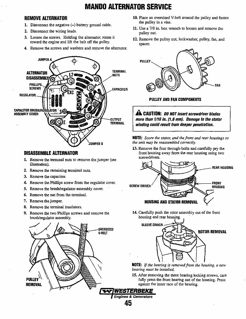
MANDO ALTERNATOR SERVICE REMOVE ALTERNATOR 1. Disconnect the negative (-) battery ground cable.
2. Disconnect the wiring leads.
3. Loosen the screws. Holding the alternator, rotate it toward the engine and lift the belt off the pulley.
4. Remove the screws and washers and remove the alternator.
AlTERNATOR
SCREWS
REGULATOR --.., ..... , •.
ASSEMBLY COYER
TERMINAL
CAPACITOR~l~~~HIRE~~~~~~~=
~(j-~~
'JUMF'ERB
DISASSEMBLE ALTERNATOR 1. Remove the termmal nuts to remove the jumper (see
illustration).
2. Remove the remaining tenninal nuts.
3. Remove the capacitor.
4. Remove the Phillips screw from the regulator cover.
5. Remove the brush/regulator-assembly cover.
6. Remove the nut from the terminal.
7. Remove the jumper.
8. Remove the terminal insulators.
9. Remove the two Phillips screws and remove the brush/regulator assembly.
PUUEY~ REMOVAL
Y·BELT
10. Place an oversized V-belt around the pulley and fasten the puJley in a vise.
11. Use a 718 in. box wrench to loosen and remove the puJley nut.
12. Remove the pulley nut, lockwasher, pulley, fan, and spacer.
PUUEY AND FAN COMPONENTS
A CAUTION: DO NOT insert screwdriver blf/des more than 1/16 In. (1.6 mm). Damage to the stator winding could result from deeper penetration.
NOTE: Score the stator, and the front and rear housings so the unit may be reassembled correctly.
13. Remove the four through-bolts and carefully pry the front housing away from the rear housing using two screwdrivers.
SCREW DRIYER
REAR HOUSING
~--FRONT HOUSING
HOUSING AND STATOR REMOVAL
14. CarefuJly push the rotor assembly out of the front housing and rear housing. .
ROTOR REMOVAL
NOTE: If the bearing is removed from the housing, a /lew bearing must be installed.
15. After removing the three bearing locking screws, care funy press the front bearing out of the housing. Press against the inner race of the bearing.
Engines & Generators
45
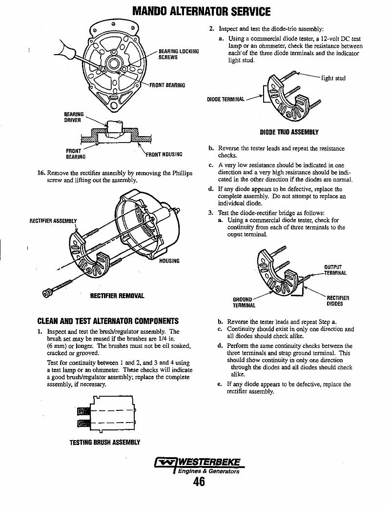
MANDO ALTERNATOR SERVICE
B~RING DRIVER
FRONT BEARING
BEARING LOCKING SCREWS
FRONT BEARING
HOUSING
16. Remove the rectifier assembly by removing the Phillips screw and lifting out the assembly.
RECTIFIER ASSEMBLY
RECTIFIER REMOVAL
CLEAN AND TEST ALTERNATOR COMPONENTS 1. Inspect and test the brush/regulator assembly. The
brush set may be reused if the brushes are 114 in. (6 mm) or longer. The brushes must not be oil soaked, cracked or grooved.
Test for continuity between 1 and 2, and 3 and 4 using a test lamp or an ohmmeter. These checks will indicate a good brush/regulator assembly; replace the complete assembly, if necessary.
TESTING BRUSH ASSEMBLY
2. Inspect and test the diode-trio assembly:
a. Using a commercial diode tester, a 12-volt DC test lamp or an ohmmeter, check the resistance between each' of the three diode terminals and the indicator light stud.
light stud
DIODE TERMINAL
DIODE TRIO ASSEMBLY
b. Reverse the tester leads and repeat the resistance checks.
c. A very low resistance should be indicated in one direction and a very high resistance should be indicated in the other direction if the diodes are normal.
d, If any diode appears to be defective, replace the complete assembly. Do not attempt to replace an individual diode.
3. Test the diode-rectifier bridge as follows: a. Using a commercial diode tester, check for
continuity from each of three terminals to the ouput terminal.
TERMINAL
OUTPUT I
RECTIFIER DIODES
b. Reverse "the tester leads and repeat Step a. c. Continuity should exist in only one direction and
all diodes should check alike.
d. Perform the same continuity checks between the three terminals and strap ground terminal. This should show continuity in only one direction
through the diodes and all diodes should check alike.
e. If any diode appears to be defective, replace the rectifier assembly.
Engines & Generators
46
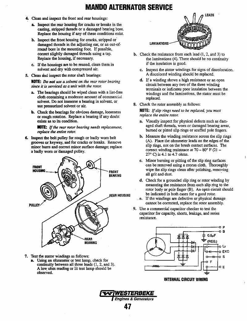
MANDO ALTERNATOR SERVICE 4, Clean and inspect the front and rear housings:
a. Inspect the rear housing for cracks or breaks in the casting, stripped threads or a damaged bearing bore. Replace the housing if any of these conditions exist.
b. Inspect the front housing for cracks, stripped or' damaged threads in the adjusting ear, or an out-ofround bore in the mounting foot. If possible, correct slightly damaged threads using a tap. Replace the housing, if necessary.
c. If the housings are to be reused, clean them in solvent and dry with compressed air.
S. Clean a'nd inspect the rotor shaft bearings:
NOTE: Do not use a solvent on the rear rotor bearing since it is serviced as a unit with the rotor.
a. The bearings should be wiped clean with a lint-free cloth containing a moderate amount of commercial solvent. Do not immerse a bearing in solvent, or use pressurized solvent or air.
b. Check the bearings for obvious damage, looseness or rough rotation. Replace a bearing if any doubt exists as to its condition.
NOTE: If the rear rotor bearing needs replacement, replace the entire rotor.
6. Inspect the belt pulley for rough or badly worn belt grooves or keyway, and for cracks or breaks. Remove minor burrs and correct minor surface damage; replace a badly worn or 'damaged pulley.
FRONT BEARING
7. Test the stator windings as follows: a. Using an ohmmeter or test lamp, check for
continuity between all three leads (1, 2, and 3). A lo~ ohm reading or lit test lamp should be observed.
HOUSING
LAMINATIONS
b. Check the resistance from each lead (I, 2, and 3) to the laminations (4). There should be no continuity if the insulation is good.
c. Inspect the stator windings for signs of discoloration. A discolored winding should be replaced.
d. If a winding shows a high resistance Or an open circuit between any two of the three winding terminals or indicates poor insulation between the windings and the laminations, the stator must be replaced.
8. Check the rotor assembly as follows:
NOTE: If slip rings need to be replaced, you must replace the entire rotor.
a. Visually inspect for physical defects such as damaged shaft threads, worn or damaged bearing areas, burned or pitted slip rings or scuffed pole fingers.
b. Measure the winding resistance across the slip rings (A). Place the ohmmeter leads on the edges of the slip rings, not on the brush contact surfaces. The correct winding resistance at 70 - 80° F (21 -27° C) is 4.1 to 4.7 ohms.
c. Minor burning or pitting of the slip ring surfaces can be removed using a crocus cloth. Thoroughly wipe the slip rings clean after polishing, removing all grit and dust. .
d. Check for a grounded slip ring or rotor winding by measuring the resistance from each slip ring to the rotor body or pole finger (B). An open circuit should be indicated in both cases for a good rotor.
. e. If the windings are defective or physical damage cannot be corrected, replace the rotor assembly.
9. Use a commercial capacitor checker to test the capacitor for capacity, shorts, leakage, and series resistance.
.I. O.5.F
.... (REG.)
F
INTERNAL CIRCUIT WIRING
P B
12 EXC
5
E
Engines & Generators
47
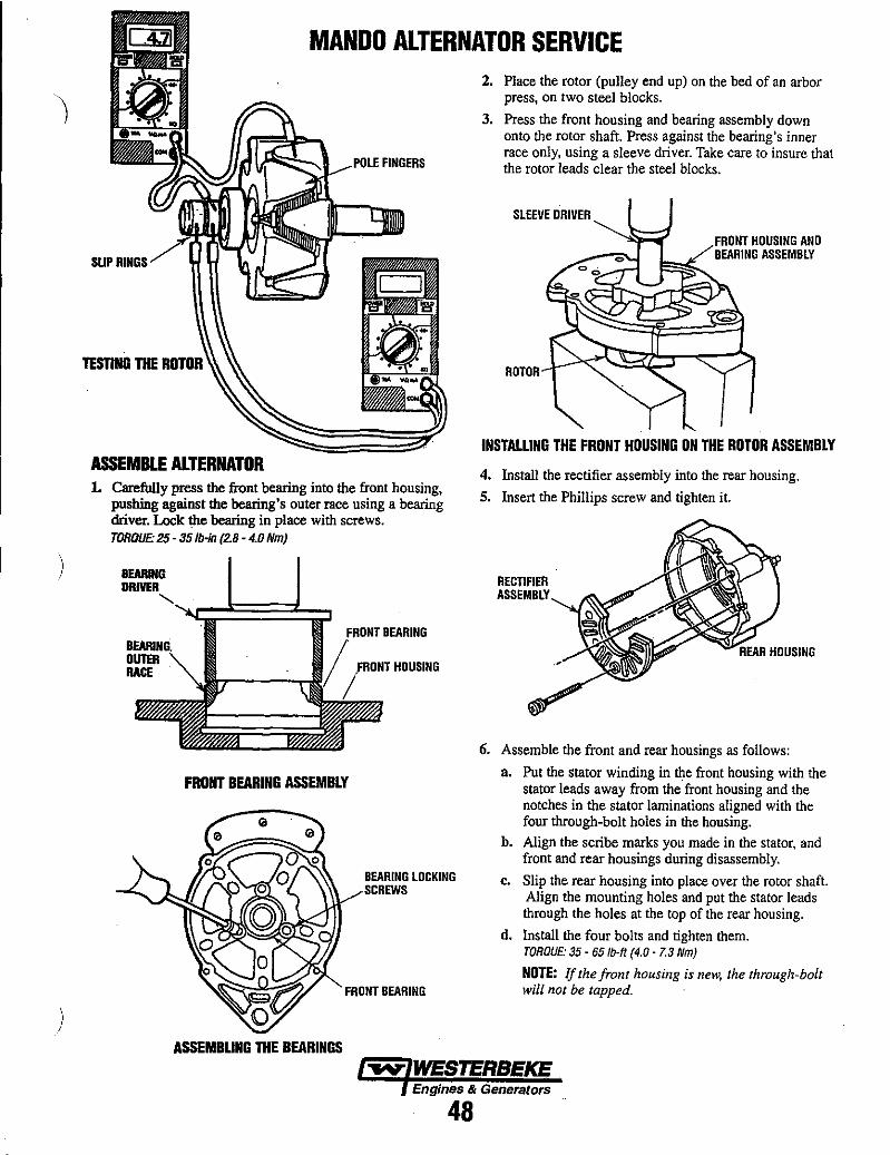
)
)
MANDO ALTERNATOR SERVICE
FINGERS
SUP b,U',."'"
TEsnNG THE ROTOR
ASSEMBLE ALTERNATOR 1. Carefully press the front bearing into the front housing,
pushing against the bearing's outer race using a bearing driver. Lock the bearing in place with screws. TORQUE: 25 - 351b-in (2.B - 4.0 Nm)
OUTER IIACf HOUSING
FRONT BEARING ASSEMBLY
ASSEMBLING THE BEARINGS
BEARING LOCKING SCREWS
FRONT BEARING
2. Place the rotor (pulley end up) on the bed of an arbor press, on two steel blocks.
3. Press the front housing and bearing assembly down onto the rotor shaft. Press against the bearing's inner race only, using a sleeve driver. Take care to insure that the rotor leads clear the steel blocks.
SLEEVE DRIVER
FRONT HOUSING AND BEARING ASSEMBLY
ROTOR
INSTALLING THE FRONT HOUSING ON THE ROTOR ASSEMBLY
4. Install the rectifier assembly into the rear housing.
5. Insert the Phillips screw and tighten it.
RECTIFIER ASSEMBLY
6. Assemble the front and rear housings as follows:
a. Put the stator winding in the front housing with the stator leads away from the front housing and the notches in the stator laminations aligned with the four through-bolt holes in the housing.
b. Align the scribe marks you made in the stator, and front and rear housings during disassembly.
c. Slip the rear housing into place over the rotor shaft. Align the mounting holes and put the stator leads through the holes at the top of the rear housing.
d. Install the four bolts and tighten them. TORQUE: 35 - 65/b-tt (4.0 - 7.3 Nm)
NOTE: If the front housing is new, the through-bolt will not be tapped.
Engines & Generators
48
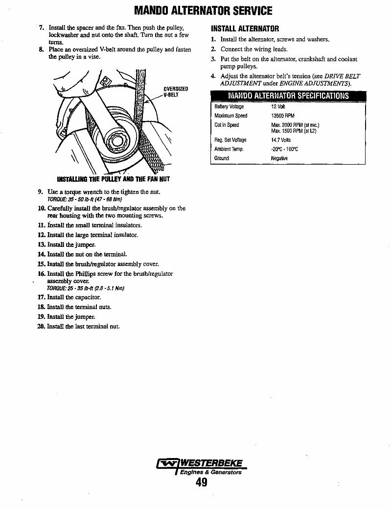
MANDO ALTERNATOR SERVICE 7. Install the spacer and the fan. Then push the pulley,
lockwasher and nut onto the shaft. Turn the nut a few turns.
8. Place an oversized V-belt around the pulley and fasten the pulley in a vise.
OVERSIZED V-BELT
INSTAlLING THE PULlEY AND THE FAN NUT
9. Use a torque wrench to the tighten the nut. TOROUE: 35 - 50 Ib-ft (47 - 68 Nm)
10. Carefully instaU the brush/regulator assembly on the rear housing with the two mounting screws.
11. IDstaU the small terminal insulators.
12. InstaU the large terminal insulator.
13. lnstaU the jumper.
14. InstaU the nut on the terminal.
lS.lnstaU the brush/regulator assembly cover.
16. lnstaU the Phillips screw for the brush/regulator assembly cover. TOROUE: 25 • 351b-ft (2.8 - 5.1 Nm)
17. lnstall the capacitor.
18. InstaU the terminal nuts.
19. lnstall the jumper.
20. lnstaU the last terminal nut.
INSTALL ALTERNATOR 1. Install the alternator, screws and washers.
2. Connect the wiring leads.
3. Put the belt on the alternator, crankshaft and coolant pump pulleys.
4. Adjust the alternator belt's tension (see DRIVE BELT ADJUSTMENT under ENGINE ADJUSTMENTS).
MANOO ALTERNATOR SPECIFICATIONS -----
Battery Voltage 12 Volt
Maximum Speed 13500 RPM
Cut in Speed Max. 2000 RPM (at exc.) Max. 1500 RPM (at l2)
Reg. Set Voltage 14.7 Volts
Ambient Temp. -20'C - 100°C
Ground Negative
~ WESTERBEKE Engines & Generators
49
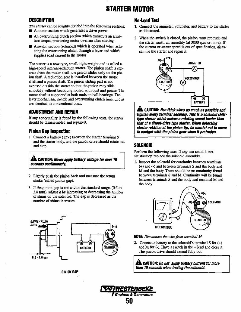
STARTER MOTOR DESCRIPTIDN TIuJ .fllrte, can be roughly divided into the following sections: • A motor section which generates a drive power. • An overrunning clutch section which transmits an arma
ture torque, preventing motor overrun after starting.
• A switch section (solenoid) which is operated when actuating the overrunning clutch through a lever and which supplies load current to the motor.
The starter is a new type, small, light-weight and is called a high-speed internal-reduction starter. The pinion shaft is separate from the motor shaft; the pinion slides only on the pinion shaft. A reduction gear is installed between the motor shaft and a pinion shaft. The pinion sliding part is not exposed outside the starter so that the pinion may slide smoothly without becoming fouled with dust and grease. The motor shaft is supported at both ends on ball bearings. The lever mechanism, switch and. overrunning clutch inner circuit are identical to conventional ones.
ADJUSTMENT AND REPAIR If any abnormality is found by the following tests, the starter should be disassembled and repaired.
Pinion Gap Insp.ection I. Connect a battery (12V) between the starter terminal S
and the starter body, and the pinion drive should rotate out and stop.
A CAonON: Never apply batt8/'f w/tage for ollBr 10 SBconds continuously.
2. Lightly push the pinion back and measure the retom stroke (called pinion gap).
3. If the piniOli gap is not within the standard range, (0;5 to 2.0 mm), adjust it by mcreasing or decreasing the number of shims on the solenoid. The gap is decreased as the number of shims increases.
GENTLYPUSH BACK
0.5 - 2.0 mm
PINION GAP
No·Load Test 1. C'onnect the ammeter, voltmeter, and battery to the starter
as illustrated.
2. When the switch is closed, the pinion must protrude and . the starter must run smoothly (at 3000 rpm or more). If
the current or starter speed is out of specification, disassemble the starter and repair it.
AMMETER
.-----------1 BATIERY
A CAonON: IIss thiC/C wires as much as possible and tighten ellBry terminal S8t:urely. This Is a solenoid shlfttype startar which makss a rotating sound lOUder than that of a dlrect·drlllB type statter. When det,ctlng statter rotation at the pinion tip, be careful not to come In contact with the pinion gear when It protrudss.
SOLENOID Perform the following tests. If any test resnlt is not satisfactory, replace the solenoid assembly.
1. Inspect the solenoid for continnity between terminals (+) and (-) and between terminals S and the body and M and the body. There should be no continuity found between terminals S and M. Continuity will be found between terminals S and the body and terminal M and the body.
MUlTIMETER
NOTE: Disconnect the wire from terminal M.
2. Connect a battery to the solenoid's terminal S for (+) and M for (-). Have a switch in the + lead and close it. The pinion drive should extend fully out.
A CAUTION: 00 not apply battery current for more than 10 SBconds when testing the solenOid.
Engines & Generators
50

STARTER MOTOR
CONIIECTI~R OFF
3. Holdingt£st With a battery connected to the solenoid terminal S (+) and to the starter body, manually pull out the pinion fuIly_ The pinion must remain at that position even ""hen released from holding with your hand.
HOLD. TEST ~CIINNECTOR OFF
STABlER DISASSEMBLY L Disconnect the wire from the solenoid terminal M (-).
2. Loosen the two screws fastening the solenoid. Remove the solenoid assembly.
3_ Remove the two long through bolts and two screws fastening the brush holder. Remove the rear bracket.
4_ With the brushes pulled away from the armature, remove the yoke and brush holder assembly. Then pull the armature oul
5_ Remove the cover, pry the snap ring out, and remove the washer.
6. Unscrew the bolts and. remove the center bracket. At the same time, the washers for the pinion shaft end play adjustment will come off.
PINION
STARTER II010R
INSPECT WEAR & CHIP,PING.
SNAP AI." __ -jli).~;.v
LEVER SPRING
4. RetIJm test:. With a battery connected to the solenoid teroonal M (-) and to the starter body, manually pull out the pinion fully. The pinion must return to its original position when released from holding by hand.
RETURN TEST
7. Pull out the reduction gear lever and lever spring from the front bracket.
S. On the pinion side, pry the snap ring out, and pull out the pinion and pinion shaft.
9. At each end of the armature, remove the ball bearing with a bearing puller. It is impossible to replace the ball bearing press-fitted in the front brackel If that bearing has worn off, replace the front bracket assembly.
TERMINAL
l I
SHIMS
BRUSHES --"'11!l I
.--J ARMATURE~~
_.' NOTE: Inspect, clean and replace if necessary brush, commuter, solenoid, armalUre, etc. See the following pages.
Engine. & Generator.
51
COLISEUM GENERATOR DESCRIPTION The Coliseum (4-pole) generators are self-exciting, synchronous, brushless models. Brushless excitation is obtained by electromagnetic transmission of the excitation power through the air gap of the synchronous exciter. The generators are single-phase 4 leads at 60Hz and are manufactured and tesred according to NEMA standards, ISO standards and IEC recommendations. 'Generator: The generator design is based on a multilaminared magnetic circuit with salient poles on the rotor. The rotor is of a special compact construction with an integral ctamper cage and a field winding section conductor wound directly on the rotor. A special interpole fixation combined to the mechanical compactness of the winding ensures a highly efficient generator ..
Generator Maintenance • Maintaining reasonable cleanliness is important.
Connections of terminal boards and rectifiers may become corroded, and insulation surfaces may start conducting if salts, dus~ engine exhaus~ carbon, etc. are allowed to build up. Clogged ventilation openings may cause excessive heating and reduced life of windings.
• For unusually severe conditions, thin rust-inhibiting petroleum-base coatings, should be sprayed or brushed over all surfaces to reduce rusting and corrosion.
• In addition to perindic cleaning, the generator should be inspected for tightness of all connections, evidence of overheated terminals and loose or damaged wires.
• The drive discs on single beiuing generators should be checked periodically if possible for tightness of screws and for any evidence of incipient cracking failure. Discs should not be allowed to become rusty because rust may accelerate cracking. The bolts which fasten the drive disc to the generator shaft must be hardened steel SAE grade 8, identified by 6 radial marks, one at each of the 6 comers of the head,.
Exciter: The exciter is a six-pole synchronous generator willi salient poles on the stator and a cylindrical armature on the rotor. The exciter rotor and the rotating rectifier are mounted on the shaft with the main generator rotor.
Excitation System: The system is excited automatically by means of residual magnetism of the magnetic circuits of the generator and exciter and stabilized by the permanent magnet in one of the exciter poles.
Winding Connections: The single-phase synchronous generator has 4 stator leads and can be configured to 120 or 240 volt output.
Bearings: The bearings are sealed type and permanently greased requiring no maintenance during their working life (approx. 30,000 hours).
• The rear armature bearing is lubricated and sealed; no maintenance is required. However, if the bearing becomes noisy or rough-sounding, have it replaced.
• Examine bearing at perindic intervals. No side movement of shaft should be detected when force is applied. if side motion is detectable, bearings are wearing or wear on shaft of bearing socket outside bearing has occurred. Repair must be made quickly or major components will rub and cause major damage to generator.
Carbon Monoxide Detector WESTERBEKE recommends mounting a carbon monoxide detector in the vessels living quarters. Carbon monoxide, even in smaJJ amounts is deadly. The presence of carbon monoxid~ indicates an exhaust leak from the engine or generator, from the exhaust elbow/exhaust hose, or that fumes from the vessels exhaust or a nearby vessel are entering your boat
If carbon monoxide is presen~ ventilate the area with . clean air and correct the problem immediately!
~ WESTERBEKE Engines & Generators
52

COLISEUM GENERATOR TO ACCESS THE ROTOR ASSEMBLY FOR TROUBLESHOOTING 1. Remove the six (5mm) allen head screws that hold the
end cover to the generator housing.
2. At the 9:00 and 3:00 O'clock position are threaded bosses. Thread a bolt (8mm - 1.5 x 50mm) into these two bosses. 'This will push the end cover off the housing exposing the rotor assembly.
When re-1nstalling: Place a small amount of petroleum jelly on the rotor bearing "O"_ring located in the cover boss. Position the cover onto the bearing and thread the six (5mm) allen head screws back in place (finger tight). TIghten the screws in a cris-cross manner drawing the end cover onto the bearing. When fully on, tighten the screws securely.
NOTE: A transient voltage supressor is connected between the (+) and (-) terminals of the rotating field windings (underneath).
~SUPRESSOR \ \ FRONT (TOP)
VIEW
SUPRESSOR
WIRING SCHEMATIC
ROTOR TROUBLESHOOTING (Low voltage Output)
Rotating Field Winding 1. Position the rotor as shown above with the (+) and (-)
connections at 12 O'Clock.
2. Place the ohm meter leads across the (+) and (-) connections and record the ohm valve. Also check that there is no continuity between either the (+) or the (-) connections and the rotor shaft.
Diodes and Auxiliary Windings 1. Test the diodes on the (+) and (-) sides by lifting the
leads from the auxiliary winding studs A, B, and C as illustrated. Test each diode for an open or short.
NOTE: The three pairs of windings should hove the same ohm values.
2. Test the auxiliary windings in pairs. Check the ohm values between A and B, B and C, A and C and record. Check that there is no continuity between the rotor shaft and windings A, B, and C ..
3. Test each diode individually. A resistance value should be found through the diode in one direction and, with the meter probes reversed, show no ohm value. The ohm value found for each diode should be approximately the same.
TEST EACH OF THE WINDING LEADS INDIVIDUALLY AS SHOWN THEN DO THE SAME WITH BAND C.
~ WES'7l:RBEKE A FAULTY DIODE CAN BE PRESSED OUT AND REPLACED
Engines & Generators
53

COLISEUM GENERATOR TROUBLESHOOTING In some cases, it is difficult to find out on the basis of the existing indications on which part of the generator the fault has occurred. For this reason, it is recommended to follow the step by step procedure below:
4. In case of a faulty regulator operation, the trouble may lie ruso in the generator. This can be easily verified by checking the generator operation with separate excitation. For this check it is necessary to follow the EXCITATION MAGNETIZATION PROCEDURE outlined on page 5 in this manual.
1. Inspect visually the condition of all connections, tenninal boards, terminals and the excitation system components.
2. Inspect visually for indications of damage to the windings on the generator.
S. A burning smell or signs of smoke would indicate a short in the windings or a mechanical failure.
3. Check the operation of the voltage regulator. Check if the voltage.regulator is connected correctly and properly adjusted.
FAULT PROBABLE CAUSE
NO AC VOLTAGE OUTPUT AT NO LOAD. 1. Short or open in the 3. Open in exciter main stator winding. stator winding.
2. Four or more shorted or 4. Open in rotating open diodes on exciter rotor. fie,ld winding.
5. Shorted supressor.
RESIDUAL VOLTAGE PRODUCED AT 1. Faulty voltage regulator. NO LOAD 15 • 20 VOLTS AC.
2. Short or open in the AC wiring to the voltage regulator.
LOW AC VOLTAGE OUTPUT AT 1. Reset voltage potentiometer. 4. Faulty voltage regulator. NO LOAD 60 -100 VAC.
2. Shorted diodes in exciter rotor 1 to 3 diodes. 5. Short in exciter stator windings.
3. Shorted exciter rotor winding. 6. Short in rotating field winding.
HIGH AC OUTPUT VOLTAGE 1. Reset voltage potentiometer. 150 VAC OR HIGHER.
2. Faulty voltage regulator.
UNSTABLE VOLTAGE OUTPUT. 1. The potentiometer on the 2. Faulty voltage regulator. (ENGINE SPEED STEADY) voltage regulator needs
adjusting.
AC VOLTAGE DROP UNDER LOAD 1. Diode(s) on exciter rotor 60 ·100 VOLTS AC. breaking down when load is
.applied (inductive) 1-3 diodes.
VERY LOW AC OUTPUT 1. Loss of residual magnetism. VOLTAGE 4 - 10 VAC
NOTE: AC GENERATOR TROUBLESHOOTING MUST BE PERFORMED WITH THE ENGINE OPERATING AT 60 HZ
~ WESTERBEKE Engines & Generelore
54
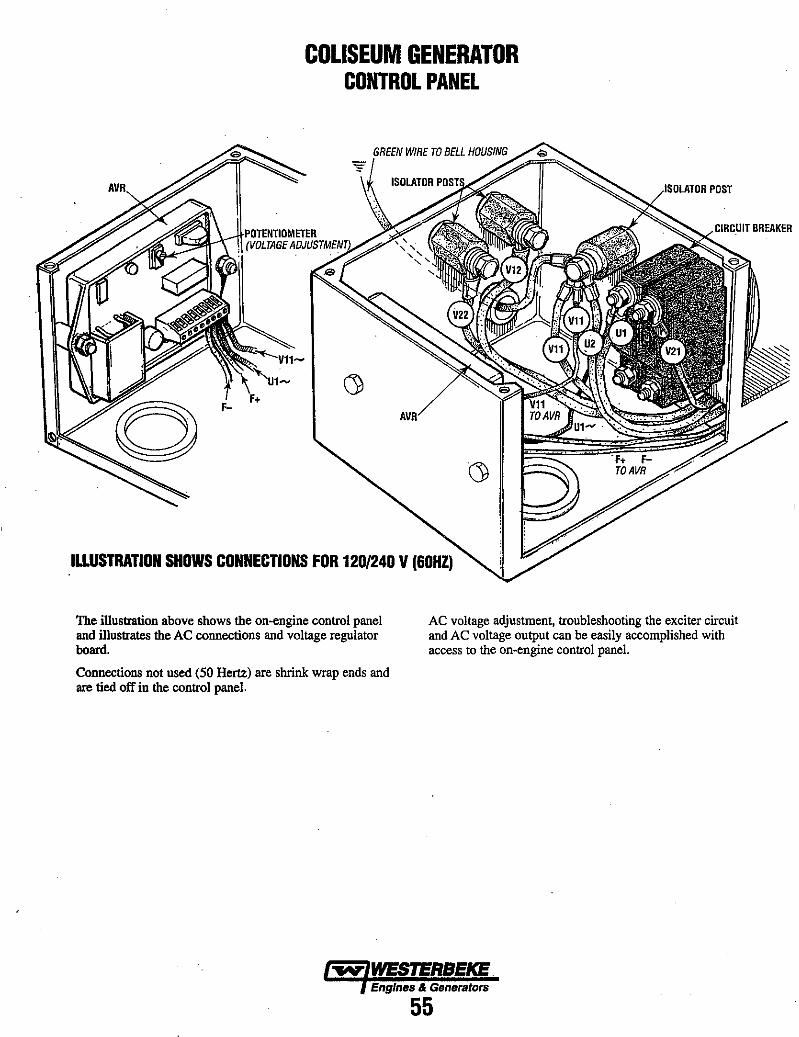
COLISEUM GENERATOR CONTROL PANEL
ILLUSTRATION SHOWS CONNECTIONS FOR 120/240 V (60HZ)
/1~DILATlIR POST
The illustration above shows the on-engine control panel and illustrates the AC connections and voltage regulator board.
AC voltage adjustment, troubleshooting the exciter circuit and AC voltage output can be easily accomplished with access to the on-engine control panel.
Connections not used (50 Hertz) are shrink wrap ends and are tied off in the control panel.
~ WESTERBEKE Engines & Generators
55
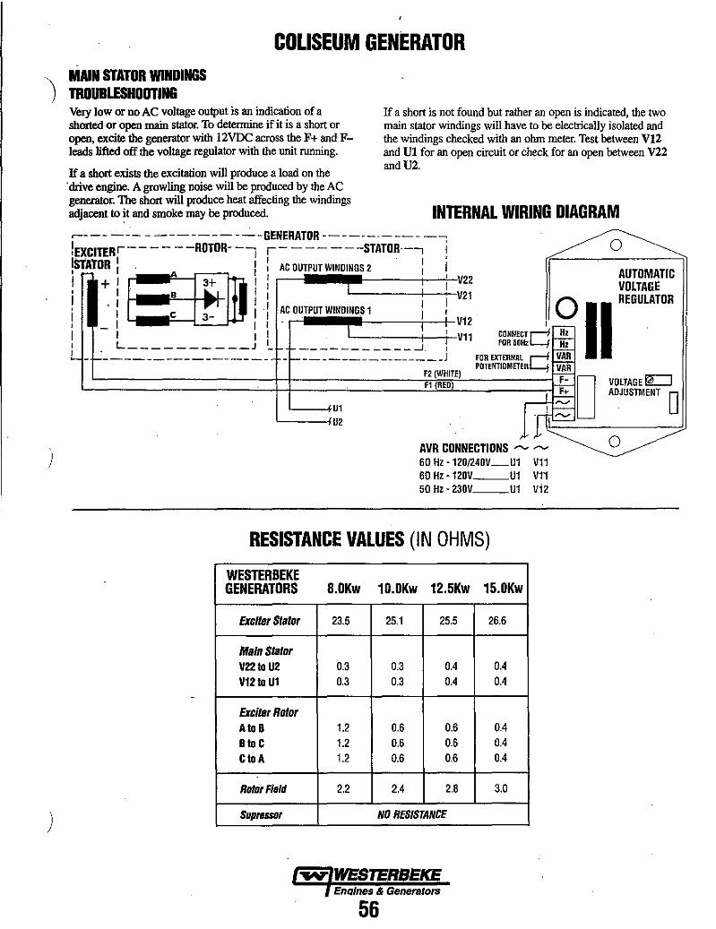
COLISEUM GENERATOR '\ MAIN STATOR WINDINGS ) mOUBLESHOOTING
)
)
Very low or no AC voltage oUlput is an indication of a shorted or open main stator. To detennine if it is a short or open, excite the generator with 12VDC across the F+ and Fleads lifted off the voltage regulator with the unit running.
If a short exists the excitation will produce a load on the . drive engine. A growling noise will be produced by the AC generator. The short will produce heat affecting the windings adjacent to it and smoke may be produced.
If a short is not found but rather an open is indicated, the two main stator windings will have to be electrically isolated and the windings checked with an ohm meter. Test between VI2 and VI for an open circuit or check for an open between V22 andV2.
INTERNAL WIRING DIAGRAM ~--- --- - ----------GENERATOR ------.------iEJ(CITERr---- --ROTOR--~ r- ------STATOR·-, i o I I I I ' ,STAtOR I i I AC OUTPUT WINDINGS 2 : I AUTOMATIC
I + : /. : 93+ I i ' ~:~ VOLTAGE . I I I I 0 REGULATOR
I c 3- I I AC OUTPUT WINDINGS 1 I II -L _________ J 1_ _ __________ ..J ,~~~ ;g~~~~~d:: .
- ----------------- - ________________ 1 ~~~E~~~NJiRc; ~::
~~ \~:~~EJ F- D VOLTAGE ~ , ~ ADJUSTMENT 0
'----IU1 L----iU2
AVR CONNECTIONS """ ----60 Hz -12D/240V_U1 V11 60 Hz -120V __ U1 V11 50 Hz - 230V __ U1 V12
RESISTANCE VALUES (IN OHMS)
WESTERBEKE GENERATORS 8.0Kw 10.0Kw 12.5Kw 15.0Kw
Excller Slalor 23.5 25.1 25.5 26.6
MainStalor V22 to U2 0.3 0.3 0.4 0.4
V12 to U1 0.3 0.3 0.4 0.4
Exciler Rolor A to B 1.2 0.6 0.6 0.4 B to C 1.2 0.6 0.6 0.4
CtoA 1.2 0.6 0.6 0.4
RolorF/sld 2.2 2.4 2.8 3.0
Suprsssor NO RESISTANCE
EnQ/nes & Generators
56
o
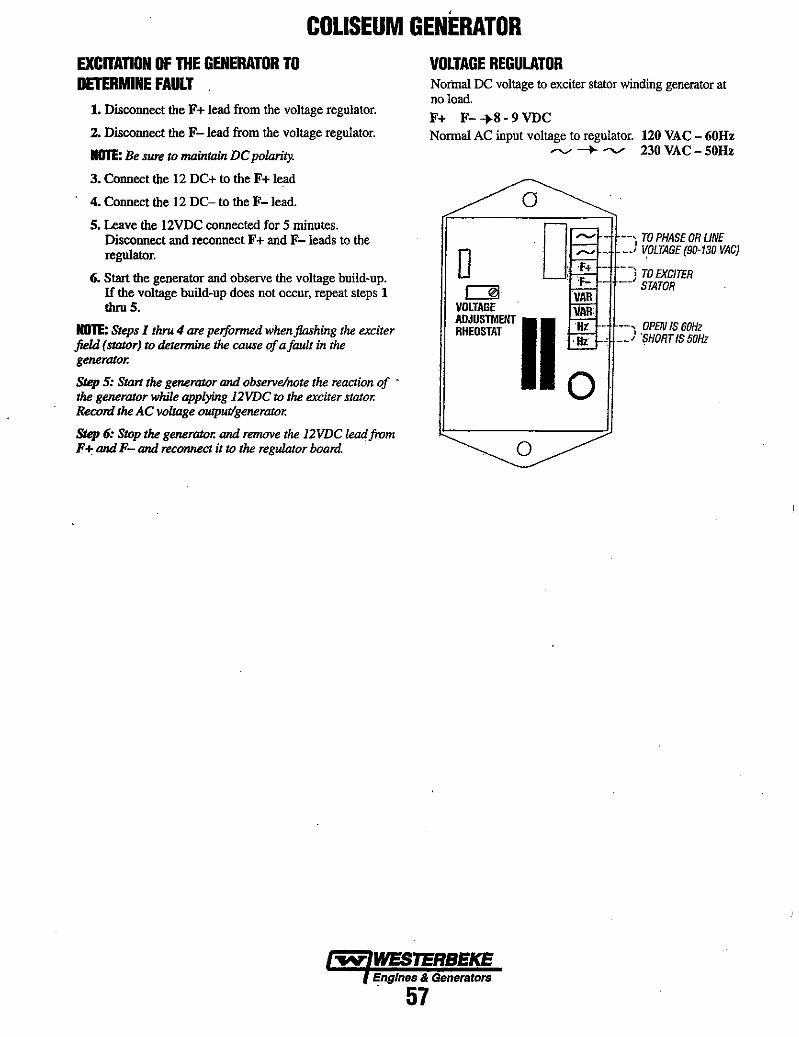
,
COLISEUM GENERATOR EXCITATION OF THE GENERATOR TO DETERMINE FAULT .
1. Disconnect the F + lead from the voltage regulator.
2. Disconnect the F-lead from the voltage regulator.
NOTE: Be sure to maintain DC polarity.
3. Connect the 12 DC+ to the F+ lead
4. Connect the 12 DC- to the F-lead.
5. Leave the 12VDC connected for 5 minutes. Disconnect and reconnect F + and F-Ieads to the regulator.
6. Start the generator and observe the voltage build-up. If the voltage build-Up does not occur, repeat steps 1 thru 5.
NOTE: Steps 1 thru 4 are performed when flashing the exciter field (stator) to determine the cause of afault in the generator.
SlIlp 5: Start the generator and observelnote the reaction of . the generator while applying 12VDC to the exciter stator. Record the AC voltage ouJput/generator.
SIIlp 6: SUJp the generator. and remove the 12VDC leadfrom F + and F- and reconnect it to the regulator board.
VOLTAGE REGULATOR Nortna! DC voltage to exciter stator winding generator at no load.
F+ F--+8·9VDC Norma! AC input voltage to regulator. 120 VAC - 60Hz
,...", -+......,.. 230 VAC - 50Hz
a "'"'~·ff-·-, TO PHASE OR LINE
o ~
VOLTAGE (90-130 VAC)
L--"rf.l-.~+---; TO EXC/TER STATOR
VOLTAGE
~II HI---, OPEN IS 60Hz I-'H--' 'SHORT/550Hz
o o
~ WESTERBEKE Engines & Generators
. 57

COLISEUM GENERATOR
RESTORING RESIDUAL MAGNETISM TO THE GENERATOR The initial excitation of the generator is assured by the pennanent magnet built in one of the exciter stator poles. Trouble with the initial excitation can occur after prolonged storage or after a service repair that dismantles the exciter. In some rare instances, it may be the result of rough transport or
. handling. To restore the residual magnetism necessary to begin the voltage build-up, excite the generator with 40 -60VDC by following the procedure below:
o r::Jl
VOLTAGE
o TO PHASE OR LINE
~-.-II---,I VOLTAGE (90-130 VAC)
11:f-W--tt·--~ TO EXCITER STATOR
1. Disconnect the F+ lead from the voltage regulator.
2. Disconnect the F-lead from the voltage regulator.
NOTE: Be sure to maintain DC polarity.
3. Connect the 40 - 6OVDC+ to the F + lead
RHEOSTAT ADJUSTMENT II ~-jl~-·-, OPEN IS 60Hz SHORT IS 50Hz
o 4. Connect the 40 - 60VDC- to the F- lead.
5. Leave connected for 2 -3 seconds. Disconnect and reconnect F + and F- leads to the regulator.
6. Start the generator and observe the voltage build-up. If the voltage build-up does not occur, repeat steps 1 thru 5.
A CAUTION: Damage to the voltage regulator will occur If he regulator Is not disconnected from the exciter field during flashing.
~ WESTERBEKE Engines & Generators
58
o

COLISEUM GENERATOR AC VOLTAGE CONNECTIONS The frnme ground wire (green) must be properly positioned when changing the AC output configuration of the AC terminal block. For making connections to the AC breaker, use terminal ends for 114 inch studs that will accept multistrand copper wire sized for the amperage rating from the hot lead connection. The frame ground green wire connects between the neutral stud and the generator frame.
Generator Frequency 1. Frequency is a direct result of engine/generator speed:
1800 rpm = 60 hertz; 1500 rpm = 50 hertz. 2. 1b change generator frequency, follow the steps below:
Connect the AC leads to the AC breaker and isolation posts as the illustrations show for the hertzlvoltage desired. Ensure that the case ground wire is connected to the correct isolation post neutral ground stud.
3. Remove or install the jumper on the automatic regulator (depending on the frequency).
NOTE: The green growui wire may be removed in those instal1ations where the AC circuit hos a separate neutral and growui circuit. This will prevent the unit from being a growui source in the vesseL
4. Open the AC circuit breaker. S. Start the generator and adjust the engine speed to the
correct no-load hertz, then adjust the voltage rheostat on the regulator to the corresponding AC output.
a AUTOMATIC VOLTAGE
CONNECT FOR 50Hz
, 0 II REGULATOR
~F:O:~RE~~:~C~ VOLTAGE~ ADJUSTMENT' 0 RHEOSTAT
AVR CONNECTIONS ---- ,...., ~O Hz • 120/240V_U1 V11 60 Hz • 120V U1 V11
. 50 Hz - 230V U1 V12
o
~ WESTERBEKE Engines & Generators
59
V21
N
-
U2
I V22
~ '1
1201240V 60Hz
) (' Ul
Vl
0 0 V
L1 L
120V60Hz Ul
6) 8
230V 50Hz Ul
8 e N L1

COLISEUM GENERATOR GENERATOR DISASSEMBLY The generator layout should be studied carefully before disassembly.
1. Remove terminal box cover. Disconnect the wire leads from the generator. If necessary, disassemble the voltage regulator support (if the Automatic Voltage Regulator is
. mounted in the terminal box) and the box complete.
2. Disconnect the voltage regulator leads and the leads from the exciter stator F + and F - to the voltage regulator.
3. Remove the fastening bolts to the generator and disassemble the generator from the prime mover by disconnecting the adapter housing and the coupling disc from the flywheel.
4. Remove the protective cover on the exciter side and loosen the bolts on the bearing shield. remove it from the housing by pulling it back.
FLYWHEEL AND BELL HOUSING ASSEMBLY (TYPICAL)
COVER HEAD BOLTS 5mm ALLEN HEAD
(COVER REMOVAL BOLTS) (8mm X 1.25)
EXCITER ROTOR
5. Remove the rotor horizontally through the flange end of the generator.
6. When the rotating rectifier is to be removed, the bearing should be pulled out first.
NOTES: During the transport of the single bearing generator, the rotor of the generator should be fixed to the housing with the coupling disc on the Jlange.
Closed type bearings are used on this series of generators. During the dismantling, be careful not to damage the protective cover rings.
To prevent damage to the rotor and stator windings while removing the rotor, place cardboard between the packnges and remove the rotor by pulling it out gently.
START MOTOR
DRIVE DISC
-.&IY: WESTERBEKE Engines & Generators
60
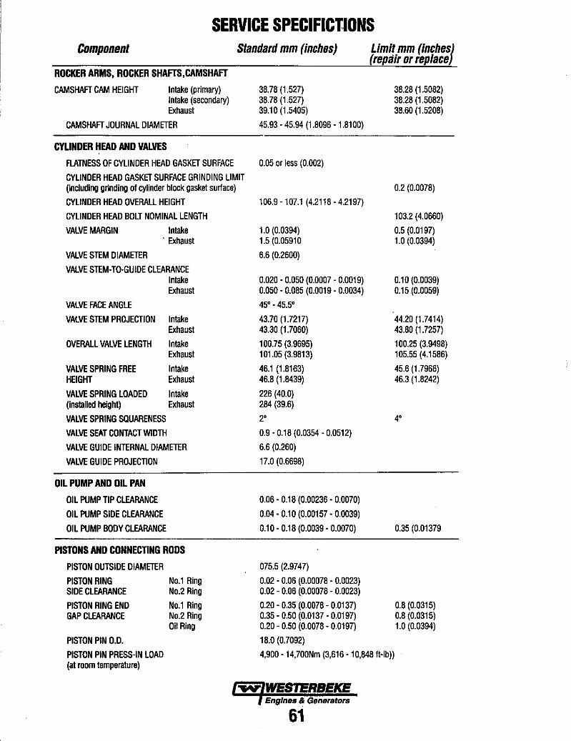
SERVICE SPECIFICY.IONS Component Standard mm (inches) Limit mm (inches)
(repair or replace) ROCKER ARMS, ROCKER SHAFTS,CAMSHAFT
CAMSHAFT CAM HEIGHT Intake (primary) Intake (secondary) Exhaust
CAMSHAFT JOURNAL OIAMETER
CYUNDER HEAD AND VALVES
FLATNESS OF CYLINOER HEAD GASKET SURFACE
CYLINDER HEAD GASKET SURFACE GRINDING LIMIT (including grinding of cylinder block gasket surface)
CYLINDER HEAD OVERALL HEIGHT
CYLINDER HEAD BOLT NOMINAL LENGTH
VALVE MARGIN Intake . Exhaust
VALVE STEM DIAMETER
VALVE STEM-TO-GUIDE CLEARANCE Intake Exhaust
VALVE FACE ANGLE
VALVE STEM PROJECTION Intake Exhaust
OVERALL VALVE LENGTH Intake Exhaust
VALVE SPRING FREE Intake HEIGHT Exhaust
VALVE SPRING LOADED Intake (installed height) Exhaust
VALVE SPRING saUARENESS
VALVE SEAT CONTACT WIDTH
VALVE GUIDE INTERNAL DIAMETER
VALVE GUIDE PROJECTION
OIL PUMP AND OIL PAN
OIL PUMP TIP CLEARANCE
OIL PUMP SIDE CLEARANCE
OIL PUMP BODY CLEARANCE
PISTONS AND CONNECTING RODS
PISTON OUTSIDE DIAMETER
PISTON RING SIDE CLEARANCE
PISTON RING END GAP CLEARANCE
PISTON PIN 0.0.
PISTON PIN PRESS-IN LOAD (at room temperature)
No.1 Ring No.2 Ring
No.1 Ring No.2 Ring Oil Ring
38.78 (1.527) 38.78 (1.527) 39.10 (1.5405)
45.93 - 45.94 (1.8096 - 1.8100)
0.05 or less (0.002)
106.9 -107.1 (4.2118 - 4.2197)
1.0 (0.0394) 1.5 (0.05910
6.6 (0.2600)
0.020 - 0.050 (0.0007 - 0.0019) 0.050 - 0.085 (0.0019 - 0.0034)
45' - 45.5'
43.70 (1.7217) 43.30 (1.7060)
100.75 (3.9695) 101.05 (3.9813)
46.1 (1.8163) 46.8 (1.8439)
226 (40.0) 284 (39.6)
2'
0.9 - 0.18 (0.0354 - 0.0512)
6.6 (0.260)
17.0 (0.6698)
0.06 - 0.18 (0.00236 - 0.0070)
0.04 - 0.10 (0.00157 - 0.0039)
0.10 - 0.18 (0.0039 - 0.0070)
075.5 (2.9747)
0.02 - 0.06 (0.00078 - 0.0023) 0.02 - 0.06 (0.00078 - 0.0023)
0.20 - 0.35 (0.0078 - 0.0137) 0.35 - 0.50 (0.0137 - 0.0197) 0.20 - 0.50 (0.0078 - 0.0197)
18.0 (0.7092)
4,900 -14,700Nm (3,616 -10,848 It-Ib))
Engines ~ Gen~rBtors
61
38.28 (1.5082) 38.28 (1.5082) 38.60 (1.5208)
0.2 (0.0078)
103.2 (4.0660)
0.5 (0.0197) 1.0 (0.0394)
0.10 (0.0039) 0.15 (0.0059)
44.20 (1.7414) 43.80 (1.7257)
100.25 (3.9498) 105.55 (4.1586)
45.6 (1.7966) 46.3 (1.8242)
4'
0.35 (0.01379
0.8 (0.0315) 0.8 (0.0315) 1.0 (0.0394)
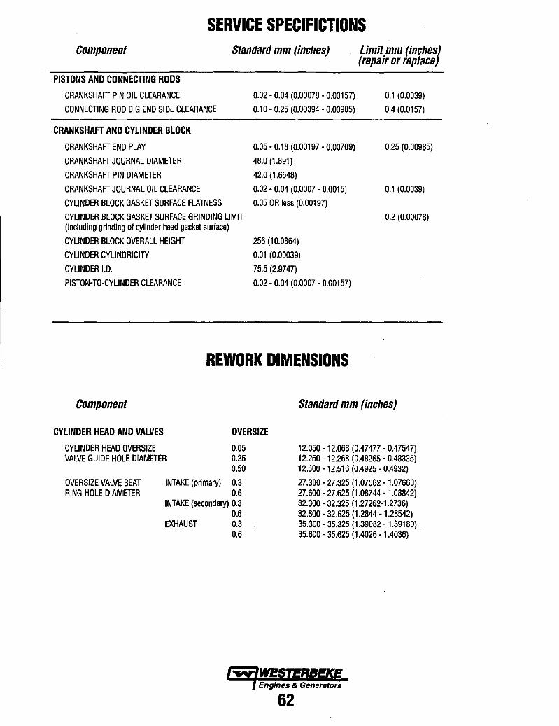
SERVICE SPECIFICTIONS Component Standard mm (inches) Limit mm (inches)
(repair or replace)
PISTONS AND CONNECTING RODS
CRANKSHAFT PIN OIL CLEARANCE
CONNECTING ROD BIG END SIDE CLEARANCE
CRANKSHAFT AND CYLINDER BLOCK
CRANKSHAFT END PLAY
CRANKSHAFT JOURNAL DIAMETER
CRANKSHAFT PIN DIAMETER
CRANKSHAFT JOURNAL OIL CLEARANCE
CYLINDER BLOCK GASKET SURFACE FLATNESS
CYLINDER BLOCK GASKET SURFACE GRINDING LIMIT (including grinding of cylinder head gasket surface)
0.02 - 0.04 (0.00078 - 0.00157)
0.10- 0.25 (0.00394 - 0.00985)
0.05 - 0.18 (0.00197 - 0.00709)
48.0 (1.891)
42.0 (1.6548)
0.02 - 0.04 (0.0007 - 0.0015)
0.05 OR less (0.00197)
0.1 (0.0039)
0.4 (0.0157)
0.25 (0.00985)
0.1 (0.0039)
0.2 (0.00078)
CYLINDER BLOCK OVERALL HEIGHT 256 (10.0864)
CYLINDER CYLINDRICITY
CYLINDER 1.0.
PISTON-TO-CYLINDER CLEARANCE
0.01 (0.00039)
75.5 (2.9747)
0.02 - 0.04 (0.0007 - 0.00157)
REWORK DIMENSIONS
Component
CYLINDER HEAD AND VALVES
CYLINDER HEAD OVERSIZE VALVE GUIDE HOLE DIAMETER
OVERSIZE
0.05 0.25
OVERSIZE VALVE SEAT RING HOLE DIAMETER
0.50
INTAKE (primary) 0.3 0.6
INTAKE (secondary) 0.3 0.6
EXHAUST 0.3 0.6
Standard mm (inches)
12.050 -12.068 (0.47477 - 0.47547) 12.250 -12.268 (0.48265 - 0.48335) 12.500 -12.516 (0.4925 - 0.4932)
27.300 - 27.325 (1.07562 - 1.07660) 27.600 - 27.625 (1.08744 - 1.08842) 32.300 - 32.325 (1.27262-1.2736) 32.600 - 32.625 (1.2844 -1.28542) 35.300 - 35.325 (1.39082 - 1.39180) 35.600 - 35.625 (1.4026 - 1.4036)
~ WESTERBEKE EngInes & Generators
62
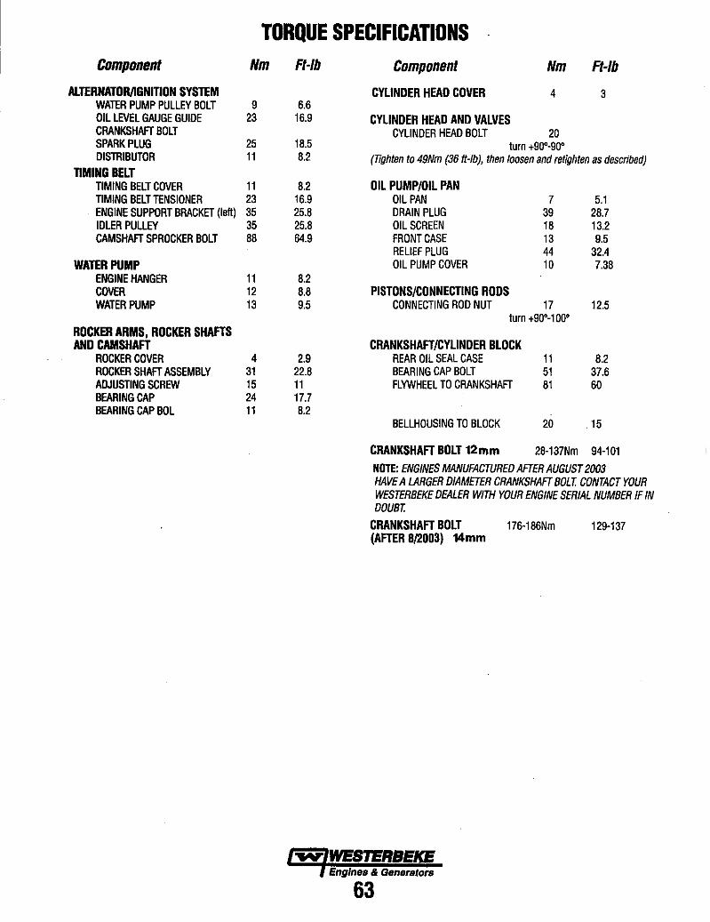
TORQUE SPECIFICATIONS Component Nm Ft-Ib Component Nm Ft-Ib
ALTERNATDRJlGNITION SYSTEM CYLINDER HEAD COVER 4 3 WATER PUMP PULLEY BOLT 9 6.6 OIL LEVEL GAUGE GUIDE 23 16.9 CYLINDER HEAD AND VALVES CRANKSHAFT BOLT CYLINDER HEAD BOLT 20 SPARK PLUG 25 18.5 turn +90'-900 DISTRIBUTOR 11 8.2 (Tighten to 49Nm (36 tt-Ib), then loosen and retighten as described)
TIMING BELT TIMING BELT COVER 11 8.2 OIL PUMP/OIL PAN TIMING BELT TENSIONER 23 16.9 OIL PAN 7 5.1 ENGINE SUPPORT BRACKET (left) 35 25.8 DRAIN PLUG 39 28.7 IDLER PULLEY 35 25.8 OIL SCREEN 18 13.2 CAMSHAFT SPROCKER BOLT 88 64.9 FRONT CASE 13 9.5
RELIEF PLUG 44 32.4 WATER PUMP OIL PUMP COVER 10 7.38
ENGINE HANGER 11 8.2 COVER 12 8.8 PISTONS/CONNECTING RODS WATER PUMP 13 9.5 CONNECTING ROD NUT 17 12.5
turn +90'-1 ~O' ROCKER ARMS, ROCKER SHAFTS AND CAMSHAFT CRANKSHAFT/CYLINDER BLOCK
ROCKER COVER 4 2.9 REAR OIL SEAL CASE 11 8.2 ROCKER SHAFT ASSEMBLY 31 22.8 BEARING CAP BOLT 51 37.6 ADJUSTING SCREW 15 11 FLYWHEEL TO CRANKSHAFT 81 60 BEARING CAP 24 17.7 BEARING CAP BOL 11 8.2
BELLHOUSING TO BLOCK 20 .15
CRANKSHAFT BOLT 12mm 28-137Nm 94-101
NOTE: ENGINES MANUFACTURED AFTER AUGUST 2003 HAVE A LARGER DIAMETER CRANKSHAFT BOLT. CONTACT YOUR WESTERBEKE DEALER WITH YOUR ENGINE SERIAL NUMBER IF IN DOUBT.
CRANKSHAFT BOLT 176-186Nm 129-137 (AFTER 812003) 14mm
-..v' WESTERBEKE Engines & Generatora
63

STANDARD HARDWAR~ BOLT HEAD MARKINGS Bolt strength classes are embossed on the head of each bolt.
Customary (inch) bolts are identifed'by markings two to grade eight (strongest). The marks correspond to two marks less than the actual grade, I.e.; a grade seven bolt will display five em,bossed marks.
Metric bolt class numbers identify bolts by their strength with 10.9 the strongest.
Use the torque values listed below when specific torque values are not available. These torques are based on clean. dry threads. Reduce torque by 10% when engine oil is ·used. Reduce torques by 30% or more, when threading capscrews into aluminum.
STANDARD BOLT & NUT TORQUE SPECIFICATIONS METRIC BOLT & NUT TORQUE SPECIFICATIONS 3M Glade 5 SAE Glade 6-7 8AE Grade 8
Capsrew Body Size TOl1lue TDI1pIe Torque 8011 Grade 4.6 Grade 4.8 Grad. 8.8 - 9.8 Grade 10.9 (Incbes) - (I11read) fI-Lb (Nm) FHb(Nm) A-tb (Nm) Di •• Wrencb Size A-lb (Nm) F~lb (Nm) Ft-Lb (Nm) FI-lb (Nm)
114 - 20 8 (11) 10 (14) 12 (16) -28 10 (14) 14 (19)
5/16 -18 17 (23) 19 (26) 24 (33) - 24 19 (26) 27 (37)
M3 5.5mm 0.3(0.5) 0.5(0.7) I (1.3) 1.5 (2) M4 7mm 0.8 (1.1) 1 (1.5) 2 (3) 3 (4.5) M5 8mm 1.5 (2.5 2 (3) 4.5 (6) 6.5(9)
318 -16 31 (42) 34(46) 44 (60) - 24 35 (47) 49(66)
M8 10mm 3(4) 4 (5.5) 7.5 (10) 11 (15) M9 13mm 7 (9.5) 10 (13) 18 (25) 35 (26)
'7116-14 49(66) . 55 (75) 70(95) Ml0 16mm 14 (19) 18 (25) 37 (50) 55 (75)
- 20 55 (75) 78 (106)
112 -13 75 (102) 85 (115) 105 (142) -20 85 (115) 120 (163)
M12 18mm 26 (35) 33 (45) 63 (85) 97 (130) M14 21 mm 37 (50) 55 (75). 103 (140) 151 (205) M16 24mm 59 (80) 85 (115) 159 (215) 232 (315)
9116 -12 110 (149) 120 (163) 155(210) -18 120 (163) 170 (231)
5/8 -II 150 (203) 167 (226) 210 (285) -18 170 (231) 240 (325)
MI8 27mm 81 (110) 118 (160) 225 (305) 321 (435) M20 30mm 118 (160) 166 (225) 321 (435) 457 (620) M22 33mm 159 (215) 225 (305) 435 (590) 620 (840)
3/4 -10 270 (366) 280 (380) 375 (508) -16 295 (400) 420 (569) M24 36mm 203 (275) 288 (390) 553 (750) 789 (1070)
718- 9 395 (536) 440 (597) 605 (820) -14 435 (590) 675 (915)
M27 41 mm 295 (400) 417 (565) 811 (1100) 1154 (1565) M30 46mm 402 (545) 568 (770) 1103 (1495) 1571 (2130)
1- 8 590 (800) 660 (895) 910 (1234) -14 660 (895) 990 (1342)
M33 51mm 546 (740) 774 (1050) 1500 (2035) 2139 (2900) M36 55mm 700 (950) 992 (1345) 1925 (2610) 2744 (3720)
NOTE: Formula to convert Ft-Lhs to Nm (Newton Meters) muillply Ft-Lhs by 1.356.
SEALANTS & LUBRICANTS GASKETS/SEAlANTS Oil based PERMATEX #2 and ifs HIGH TACK equivalent are excellent all purpose sealers. They are effective in just about any joint in contact with coolan~ raw water, oil or fuel. A light coating of OIL or LIQUID TEFLON can be used on rubber gaskets and O-rings. LOCTITE hydraulic red sealant should be used on oil adapter hoses and the oil filler assembly. Coat both surlaces of the oil pan gasket with high temp RED SILICONE sealer. When installing gaskets that seal around water (coolant) passages, coat both sides w~h WHITE SILICONE greas. High-copper ADHESIVE SPRAYS are useful for holding gaskets in position during assembly. Specialized gasket sealers such as HYLOMAR work well in applications requiring non-hardening properties. HYLDMAR is particlarly effective on copper CYlinder-head gaskets as ~ resists fuel, oil and water.
Use LIQUID TEFLON for sealing pipe plugs and fillings that connect coolant passages. Do not use tape sealants!
BOLTS & FASTENERS/ASSEMBUES Ughtly oil head bolts and other fasteners as you assemble them. Bolts and plugs that penetratelhe water jacket should be sealed With PERMATEX #2 or HIGH TACK.
When assembling the f~h .. l, coat the bolt threads with LOCTITE blue. Anti-seize compounds and thread loc~ng adhesives such as LOCTITE protect threaded components yet allows them to came apart when necessary. LOCTITE offers levels of locking according to the job.
LITHIUM based grease is waterproof, ideal for water pump bearings and stuffing boxes.
Heavily oil all sliding and reCiprocating components when assembling. Always use clean engine oil!
""" WESTl:RBEKE Engines & Generators
64
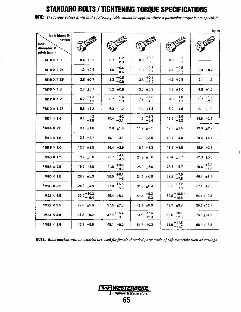
STANDARD BOLTS I TIGHTENING TORQUE SPECIFICATIONS NOTE: The torque values given in the following table should be applied where a particular torque is not specified.
kg·m
~ ~ ~ ~ ~ ~ cation
Bolt diameter X pitch (mm)
0.6 ±0.2 0.7 +0.2
0.8 +0.2
0.9 +0.2
M 6 X 1.0 -0.3 -0.3 ---0.3
M 8 x 1.25 1.3 ±0.5 1.6 +0.4
1.8 +0.5
2.1 +0.5
2.4 ±0.7 -O.S -0.6 -0.7
M10 X 1.25 2.B ±0.7 3.3 +0.8
3.8 +0.9
4.3 ±0.9 5.1 ±1.3 -0.9 -1.0
"M10 X 1.5 2.7 ±0.7 3.2 ±0.8 3.7 ±0.9 4.2 ±1.0 4.9 ±1.2
M12 X 1.25 6.2 +1.3 6.7
+1.4 7.7
+1.6 8.8
+1.8 9.7
+1.9 -1.2 ':"1.3 -1.5 -1.7 -2.0
*M12 X 1.75 5.B ±1.2 6.3 ±1.2 7.2 ±1.4 8.2 ±1.6 9.1 ±1.8
M14 X 1.5 9.7 +2
10.4 +2 11.9
+2.3 13.6
+2.6 14.5 ±2.9 -1.9 -2.1 -2.4 -2.8
*M14 X 2.0 9.1 ±1.8 9.8 ±1.9 11.2 ±2.2 12.8 ±2.5 13.6 ±2.7
M16 X 1.5 13.3 +2.7 15.1 ±3.1 17.3 ±3.5 19.7 ±4.0 20.4 ±4.1
*M16 X 2.0 12.7 ±2.5 14.4 ±2.9 16.5 ±3.3 18.8 ±3.8 19.5 ±3.9
M18 X 1.5' 19.2 ±3.8 21.7 +4.4 24.9 ±5.0 28.4 ±5.7 29.3 ±5.9 -4.3
*M18 x 2.5 19.2 ±3.8 21.8 +4.4 25.0 ±5.0 28.5 ±5.7 29.4 +5.9
-4.3 -5.8
M20 X 1.5 26.3 ±5.3 30.0 +6.1
34.4 ±6.9 39.2 +7.9
40.4 ±8.1 -6 -7.8
*M20 X 2.5 24.3 ±4.9 27.8 +5.5
31.8 ±6.4 I 36.3 +7.2 37.4 ±7.5 -5.6 -7.3
M22 x 1.5 32.0 ~1~:~ 40.4 ±8.1 46.3 +9.2 i 528+10.5 . 54.1 ±10.8 -9.3 I · -10.6
*M22 x 2.5 27.8 ±5.6 37.6 ±7.5 43.1 ±8.6 i 49.1 ±9.8 50.3 ±10.1
M24 x 2.0 45.8 ±9.2 479+15.4 . - 9.6
549+17.6 . -11.0
626+20.1 · -12.6 70.6 ±14.1
*M24 X 3.0 43.1 ±8.6 I 45.1 ±9.0 51.7 ±10.3 ! 589+11 .8 66.4 ±13.3
I · -11.7
NOTE: Bolts marked with an asterisk are usedfor fenulle threaded parts made of soft nulterials such as castings.
~ WESTERBEKE Engines & Generators
65
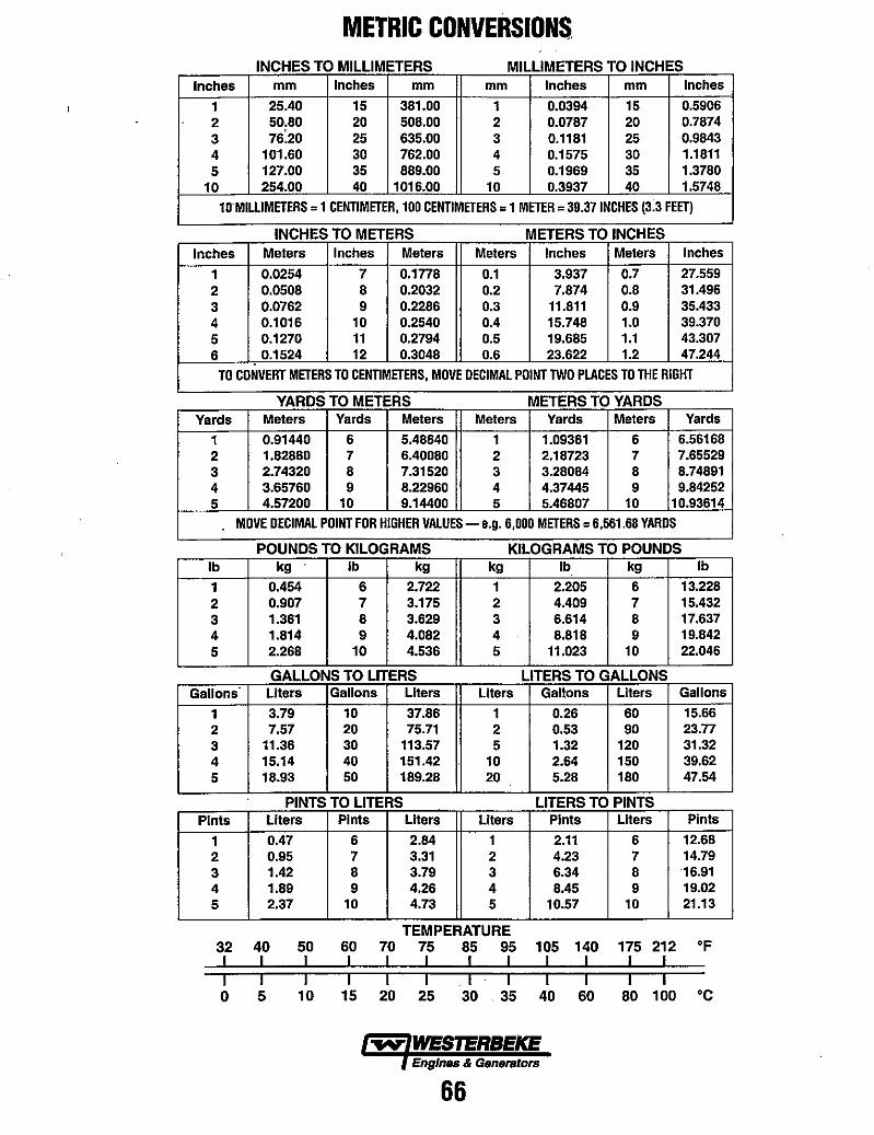
METRIC CONVERSIONS. INCHES TO MILLIMETERS MILLIMETERS TO INCHES
Inches mm Inches mm mm Inches mm Inches
1 25.40 15 381.00 1 0.0394 15 0.5906 2 50,80 20 508.00 2 0.0787 20 0.7874 3 76.20 25 635.00 3 0.1181 25 0.9843 4 101.60 30 762.00 4 0.1575 30 1.1811 5 127.00 35 889.00 5 0.1969 35 1.3780
10 254.00 40 1016.00 10 0.3937 40 1.5748
10·MILLIMETERS = 1 CENTIMETER, 100 CENTIMETERS = 1 METER = 39.37 INCHES (3.3 FEET)
INCHES TO METERS METERS TO INCHES
Inches Meters Inches Meters Meters Inches Meters Inches
1 0.0254 7 0.1778 0.1 3.937 0.7 27.559 2 0.0508 8 0.2032 0.2 7.874 0.8 31.496 3 0.0762 9 0.2286 0.3 11.811 0.9 35.433 4 0.1016 10 0.2540 0.4 15.748 1.0 39.370 5 0.1270 11 0.2794 0.5 19.685 1.1 43.307 6 0.1524 12 0.3048 0.6 23.622 1.2 47.244
TO CONVERT METERS TO CENTIMETERS, MOVE DECIMAL POINT TWO PLACES TO THE RIGHT
YARDS TO METERS METERS TO YARDS Yards Meters Yards Meters Meters Yards Meters Yards
1 0.91440 6 5.48640 1 1.09361 6 6.56168 2 1.82880 7 6.40080 2 2.18723 7 7.65529 3 2.74320 8 7.31520 3 3.28084 8 8.74891 4 3.65760 9 8.22960 4 4.37445 9 9.84252 5 4.57200 10 9.14400 5 5.46807 10 10.93614
MOVE DECIMAL POINT FOR HIGHER VALUES - e.g. 6,000 METERS = 6,561.68 YARDS
POUNDS TO KILOGRAMS KILOGRAMS TO POUNDS Ib kg Ib kg kg Ib kg Ib
1 0.454 6 2.722 1 2.205 6 13.228 2 0.907 7 3.175 2 4.409 7 15.432 3 1.361 8 3.629 3 6.614 8 17.637 4 1.814 9 4.082 4 8.818 9 19.842 5 2.268 10 4.536 5 11.023 10 22.046
GALLONS TO LITERS LITERS TO GALLONS Gallons Liters Gallons Liters Liters Gallons Liters Gallons
1 3.79 10 37.86 1 0.26 60 15.66 2 7.57 20 75.71 2 0.53 90 23.n 3 11.36 30 113.57 5 1.32 120 31.32 4 15.14 40 151.42 10 2.64 150 39.62 5 18.93 50 189.28 20 5.28 180 47.54
PINTS TO LITERS LITERS TO PINTS Pints Liters Pints Liters Liters Pints Liters Pints
1 0.47 6 2.84 1 2.11 6 12.68 2 0.95 7 3.31 2 4.23 7 14.79 3 1.42 8 3.79 3 6.34 8 16.91 4 1.89 9 4.26 4 8.45 9 19.02 5 2.37 10 4.73 5 10.57 10 21.13
TEMPERATURE 32 40 50 60 70 75 85 95 105 140 175 212 of I I I I I I I I I I I I I I I I I I I I I I I I 0 5 10 15 20 25 30 35 40 60 80 100 °C
,.yo WESTERBEKE Engines & Generators
66
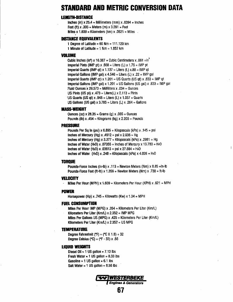
STANDARD AND METRIC CONVERSION DATA LENGTH-DISTANCE
Inches (in) x 25.4 = Millimeters (mm) x.0394 = Inches Feet (II) x .305 = Meters (m) x 3.281 = Feet Miles x 1.609 = Kilometers (km) x .0621 = Miles ,.
DISTANCE EQUIVALENTS 1 Degree of Latilude = 60 Nm = 111.120 km 1 Minute of Latitude = 1 Nm = 1.852 km
VOLUME Cubic Inches (in') x 16.387 = Cubic Centimeters x .061 =in' Imperial Pints (IMP pt) x .568 = Liters (L) x 1.76 = IMP pt Imperial Quarts (IMP qt) x 1.137 = Liters (L) x.88 = IMP qt Imperial Gallons (IMP gal) x 4.546 = Liters (L) x .22 = IMP gal Imperial Quarts (IMP qt) x 1.201 = US Quarts (US qt) x .833 = IMP qt Imperial Gallons (IMP gal) x 1.201 = US Gallons (US gal) x .833 = IMP gal Fluid Ounces'x 29.573 = Milliliters x .034 = Ounces US Pints (US pt) x .473 = Liters(L) x 2.113 = Pints 'US Quarts (US qt) x .946 = Liters (L) x 1.057 = Quarts US Gallons (US gal) x 3.785 = Liters (L) x .264 = Gallons
MASS-WEIGHT Ounces (oz) x 28.35 = Grams (g) x .035 = Ounces Pounds (Ib) x .454 = Kilograms (kg) x 2.205 = Pounds
PRESSURE Pounds Per Sq In (psi) x 6.895 = Kilopascals (kPa) x .145 = psi Inches of Mercury (Hg) x .4912 = psi x 2.036 = Hg Inches of Mercury (Hg) x 3.377 = Kiiopascals'(kPa) x .2961 = Hg Inches of Water (H20) x .07355 = Inches of Mercury x 13.783 = H20 Inches of Water (HID) x .03613 = psi x 27.684 = H20 Inches of Water (H20) x .248 = Kilopascals (kPa) x 4.026 = H20
TORQUE Pounds-Force Inches (In-Ib) x .113 = Newton Meters (Nm) x 8.85 =in-Ib Pounds-Force Feet (II-Ib) x 1.356 = Newton Meters (Nm) x .738 = II-Ib
VELOCITY - Miles Per Hour (MPH) x 1.609 = Kilometers Per Hour (KPH) x .621 = MPH
POWER Horsepower (Hp) x .745 = Kilowatts (Kw) x 1.34 = MPH
FUEL CONSUMPTION Miles Per Hour IMP (MPG) x .354 = Kilometers Per Liter (Km/L) Kilometers Per Liter (Km/L) x 2.352 = IMP MPG Miles Per Gallons US (MPG) x .425 = Kilometers Per Liter (Km/L) Kilometers Per Liler (Km/L) x 2.352 = US MPG
TEMPERATURE Degree Fahrenheit (OF) = (OC X 1.8) + 32 Degree Celsius ("C) = (OF - 32) x .56
UQUIO WEIGHTS Diesel 011 = 1 US gallon = 7.13 Ibs Fresh Water = 1 US gallon = 8.33 Ibs Gasoline = 1 US gallon = 6.1 Ibs Salt Water = 1 US gallon = 8.56 Ibs
..v: WESTERSEKE Eng/nIlS & Generators
67

SPECIAL TOOLS NOTE: These special tools are available from your local Mitsubishi Automotive Dealer.
CRANKSHAFT OIL SEAL INSTALLER For installing the front oil seal MD 998305
CRANKSHAFT REAR OIL SEAL INSTALLER For installing the rear oil seal. '---. MD 998011
PUSH ROD AND PIN SET GUIDE Used to pUll-out and press in the piston pin, MD 999584
PIN For supporting the sprocket when the camshaft sprocket is loosened or tightened, MD 998715
END YOKE HOLDER For supporting the sprocket when the camshaft sprocket is loosened or lightened. MD 990767
VALVE STEM SEAL INSTALLER MD998760
OIL PAN GASKET CUTTER For removing the oil pan to break the oil pan seal. MD 998727
VALVE SPRING COMPRESSOR MD 998772
PISTON PIN SET TOOL For press tiffing piston pins MD 998780
GUIDE 0 For removing and pressing piston pins MD 991659
VALVE SPRING COMPRESSOR For removing and installing the valve springs. ,,!D 998735
Engines & Generators
68
INDEX Alternator Specifications ................... .49 Alternator Troubleshooting .................. 31 Alternator-Disassembly and Testing ........ .43-49 Assembly & Disassembly Procedures ........... 8 Bearing Cap ............................. 27 Bearing-Connecting Rod .................... 25 Belt Timing .............................. 10 Bolt Tightening Methods ..................... 9 Bolts-Cylinder Head ....................... 19 Boring Cylinders .......................... 26 Camshaft . . . . . . . . . . . . . . . . . . . . . . . . . ....... 15 Carburetor . . . . . . . . . . . . . . . ............... .41 Coliseum Generator ....................... 52 Compression Testing ....................... 44 Connecting Rod .......................... 24 Connecting Rod Cap Nut ................... 25 Control Panel-Generator ................... .55 Coolant Circulating Pump . . . . ............... 28 Crankshaft ............................... 24 Crankshaft Bearings ...................... 25a Crankshaft Pin . . . . . . . . . . . ................. 23 Cylinder Block .......................... .26 Cylinder Head . . . . . . . . . . . . . . . . ............ 16 Cylinder Head Bolts ....................... 19 . Disassembly & Assembly Procedures ........... 8 Distributor ............................... 29 Drive Belt Adjustments .................... .40 Engine Disassembly ....................... 13 Engine Specifications ..... .................. 2 Exterior Assemblies & Disassemblies .......... 13 Front Oil Seal ............................ 21 Generator Internal Wiring ................... 56 Generator Schematic ....................... 33 Generator Troubleshooting .................. 54 Generator Wiring Diagram .................. 34 Generator-Coliseum ....................... 52 Generator-Exploded View ................... 60 Governor ............................... .42 Igniter-Testing ........................... .30 Ignition Tuning .......................... .39 Metric Conversions ..................... 65-67 Oil Pan ................................. 20 Oil Pressure .............................. 38 Oil Pump ................................ 20 Oil Seal-Front ............................ 21 Oil Seal-Rear ............................ 27
Piston Rings .....,...................... .22 Pump-Coolant . . . . . . . . . . . . . . . . . . . . . . . . . . . .28 Pump-Oil ............................... 20 Rear Oil Seal ............................. 27 Regulator-Voltage ......................... 56 Rings-Piston ...................... ...... .22 Rocker Arms ............................ .15 Rocker Cover ....................... ..... 19 Rod-Connecting ......................... .24 Schematic-Generators ..................... .33 Sealants and Lubricants ..................... 64 Service Specifications ...................... 61 Shutdown Switches ....................... 6-7 Spark Plugs ............................. .40 Special Tools ............................. 68 Specifications-Alternator ................... .49 Specifications-Engine ...................... .2 Specifications-Torque .................... 63-66 Standards and Limits ....................... 61 Starter Motor-Disassembly .................. 51 Starter Motor-Testing ...................... 50 Switches-Shutdown ....................... 6-7 Testing Oil Pressure ...................... .38 Testing the Igniter . . . . . . . . . . . . . . . . . . ...... .30 Timing Belt . . . . . . . . . . . . . . . . . . . . . . . . . ..... 10 Tools-Special ............................ 68 Torque Specifications .................... 63-66 Troubleshooting Guide-Engine ............... .4 Troubleshooting-Alternator .................. 31 Troubleshooting-Generator ................. .53 Valve Clearance ......................... .39 Valves, Valve Springs and Guides ............ .17 Voltage Regulator ......................... 56 Wiring Diagram-Generator .................. 34 Wiring Diagram-Remote Panel .............. .35 Wiring Diagram-Remote Start ............ .36-37
Engines & Genera/ors
69