Embed Size (px)
Citation preview
GASTEC QA 198 : 05-2007
GASTEC QA approval requirements 198
Multilayer pipe systems for indoor gas installations with a maximum operating
presssure up to and including 5 bar
GASTEC CERTIFICATION BV
GASTEC QA 198 : 05-2007
GASTEC QA approval requirements 198
Multilayer pipe systems for indoor gas installations with a maximum operating
presssure up to and including 5 bar
Approved by CvD Product Certification: Date 24-05-2007 Accepted by GASTEC Certification : Date 24-05-2007
GASTEC CERTIFICATION BV
GASTEC QA 198 : 05-2007
Foreword:
These requirements replace the;
GASTEC QA Approval requirements 198, Aluminium/cross linked polyethylene
(PE-X) and aluminium/polyethylene composite piping systems for indoor gas
installations, dated June 1999
and the
GASTEC QA Approval Requirements 187, Piping systems of cross-linked
polyethylene (PE-X) pipes for indoor gas installations, dated August 2001.
KIWA GASTEC Certification BV PO Box 137, 7300 AC Apeldoorn Wilmersdorf 50, 7327 AC Apeldoorn Telephone: +31-55 -5393 393 Fax: +31-55 -5393 685 E-mail: [email protected] Website: www.gasteccertification.com © 2008, GASTEC Certification BV, Apeldoorn All rights reserved. No part of this publication may be reproduced, stored in a retrieval system, or published, in any form or by any means, electronic, mechanical, photocopying, recording, or otherwise, without the prior written permission of GASTEC Certification BV.
GASTEC QA 198 : 05-2007
1
CONTENTS
1. SCOPE ...............................................................................................................2
2. PRODUCT REQUIREMENTS........................................................................2
3. pipes ..................................................................................................................2 3.1 Outer layer (ISO 17484-1, Clause 5, Pipes) ...................................................2 3.2 Dimensions of pipes (ISO 17484-1, Clause 5.3)............................................2 3.3 Calculation of the control points (ISO 17484-1, Clause 5.4.1.5) .................2 3.4 Physical properties (ISO 17484-1, Clause 5.5.2 Table 1) .............................2
4. Fittings...............................................................................................................3 4.1 Fitting reference standards (ISO 17484-1, Clause 6.1.1) .............................3 4.2 Materials ...........................................................................................................3 4.2.1 Plastic materials ...............................................................................................3 4.2.2 Metal fittings ....................................................................................................3 4.3 Rubber seals (ISO 17484-1, Clause 6.5) .........................................................4 4.4 Transition connections ....................................................................................4
5. fitness for purpose ...........................................................................................4 5.1 Diameter classes (ISO 17484-1, Clause 7.1) ..................................................4 5.2 Hydrostatic strength (ISO 17484-1, Clause 7.3, table 4)..............................4
6. pipe sleeves.......................................................................................................4 6.1 Introduction......................................................................................................4 6.2 Additional testing methods............................................................................5 6.2.1 Determining the resistance to compression .................................................5 6.2.2 Determining the resistance against impact ..................................................6 6.2.3 Determining the mass per length ..................................................................6 6.2.4 Marking.............................................................................................................7
A 1. REQUIREMENTS FOR THE QUALITY SYSTEM ......................................8
A 1.1 General ..............................................................................................................8
A 1.1.1 Quality system manager.................................................................................8
A 1.1.2 Internal quality monitoring/quality plan ....................................................8
A 1.1.3 Procedures and work instructions ................................................................8
A 1.2 Investigation and check summary ................................................................8
A 2. Model IKB-scheme or frame-IKB-scheme ..................................................13
GASTEC QA 198 : 05-2007
2
1. SCOPE
These approval requirements cover multilayer pipes and matching tensile-resistant fittings for use in indoor gas installations in sizes ranging from 12 mm up to and including 63 mm outside diameter. The system is for use in contact with 2nd and 3rd family gases in accordance with table 1 of EN 437. The maximum admissible operating pressure for these multilayer systems is 5 bar. The system is intended for indoor use at operating temperatures from -20 °C up to +60 °C. The specific functional recommendations for installation of these systems are described in the requirements of EN 1775, NEN 1078, NPR 3378-10, and/or other national and international standards and regulations.
2. PRODUCT REQUIREMENTS
Multilayer pipe systems shall meet the requirements of: ISO 17484-1:2006 Plastics piping systems — Multilayer pipe systems for indoor gas installations with a maximum operating pressure up to and including 5 bar — Part 1: Specifications for systems.
Besides ISO 17484-1:2006, the following requirements and interpretations shall be met.
3. PIPES
3.1 Outer layer (ISO 17484-1, Clause 5, Pipes)
The outer layer of pipes shall be yellow. For yellow outer layers reference materials may be used where the original pigment has been exchanged for yellow. The long term pressure strength of these materials with a new pigment shall be equal to the original reference material. The strength of the pipe with a different pigment shall be checked by hydrostatic strength testing at the control points calculated in accordance with ISO 17484-1, Clause 5.4.1.5.
3.2 Dimensions of pipes (ISO 17484-1, Clause 5.3)
The outside diameter is free. (ISO 161-1 is preferred).
3.3 Calculation of the control points (ISO 17484-1, Clause 5.4.1.5)
The failure control points at 165 h shall be used by manufacturer as product batch release test.
3.4 Physical properties (ISO 17484-1, Clause 5.5.2 Table 1)
The following interpretation of the resistance to gas constituents test shall be adhered to. 2 samples shall be filled with synthetic condensate and allowed to stand in air for 1500 h at 23 ± 2 ºC. The pressure in the sample shall be 0,4 PD. Hereafter the samples shall be tested in accordance to ISO 17484-1, Annex B, and checked for leakage and delamination of the layers.
GASTEC QA 198 : 05-2007
3
2 samples shall be by filled with synthetic condensate and stored in air for 1500 h at 23 ± 2 ºC. Subsequently the pipe shall withstand a pressure of 0,4 PD for 20 h at 80 ºC.
4. FITTINGS
4.1 Fitting reference standards (ISO 17484-1, Clause 6.1.1)
Fittings tested in accordance with ISO 17484-1, table 4: Requirements for fitness purpose of joint assembles, are deemed to fulfil the performance requirements of the relevant reference standard as mentioned in ISO 17484-1, Clause 6.1.1. The dimensions and minimum wall thickness of the fittings shall be in accordance as specified in the relevant ISO standards as mentioned in EN 17484-1, clause 6.1.1 and EN 1254-3.
4.2 Materials
4.2.1 Plastic materials
For plastic materials other than the reference materials PEX and PE a test plan, relevant to the selected material, shall be drafted in consultation with the material producer The test plan shall be such that the long term mechanical strength and chemical resistance of the material is established. The mechanical strength and chemical resistance shall be adequate for the intended use.
4.2.2 Metal fittings
Fittings shall be made from metal selected from materials either:
• Specified in relevant EN standards
• Specified in relevant ISO standards Provided that the fittings manufactured from them meet the functional requirements of this. Some of the standardized coppers and copper alloys and requirements commonly used for the manufacturing of fittings are shown in table 5.
Table 5 – requirements for copper alloy fittings
Characteristic Requirements Test parameter Test method
Copper alloys NEN-EN1254-3 Clause 4.2
Manufacturer quality system 1)
Manufacturer data
Dimensions NEN-EN1254-3 Table 3
Minimum thickness ISO 228-1 of
Construction NEN-EN1254-3 Manufacturer drawings
ISO 3126
Cast microstructure
Pneumatic pressure test , 5 bar
NEN-EN1254-3 punt5.1
ISO 1254-3, clause 5.1
Stress corrosion resistance test
No prior pickling PH 9,5 EN-ISO 6957
1) Subject to approval, minimum requirements will be part of the GASTEC QA contract.
GASTEC QA 198 : 05-2007
4
4.3 Rubber seals (ISO 17484-1, Clause 6.5)
Rubber seals shall comply with EN 549. The minimum temperature class according to EN 549 shall be A2.
4.4 Transition connections
Transition fittings may have one of the following connections. The connection shall comply with the relevant requirements or standards.
• Gas threads according to ISO 7 type R or Rp.
• Compression fittings for copper pipe connections according to GASTEC QA Approval Requirement 35
• Compression fittings for galvanised steel precision pipes according to GASTEC QA Approval Requirement 68
• Fittings, couplers and parts for soldered and screwed connections according to GASTEC QA Approval Requirement 6
• Union couplers according to NEN 2541, NEN 2542, NEN 2543, NEN 2544, NEN 2545 and NEN 3084
• Press fittings according to GASTEC QA Approval Requirement 186. Other connections are permitted in consultation with the approval body.
5. FITNESS FOR PURPOSE
5.1 Diameter classes (ISO 17484-1, Clause 7.1)
Contrary to ISO 17484-1, Clause 7.1, table 2, the in table 1 below defined diameter classes shall be used. These classes are used to establish the number of test samples as referred to in: ISO 17484-1, table 4: Requirements for fitness purpose of joint assemblies.
Table 1: Diameter classes
Diameter classes 1 2 3
External diameter (mm) de < 26 26 ≤ de D < 40 40 ≤ de ≤ 63
5.2 Hydrostatic strength (ISO 17484-1, Clause 7.3, table 4)
In addition to table 4 the hydrostatic strength of fittings and pipe joint assemblies shall be tested at 1000 h at 80ºC or 95 ºC at the failure control point using the calculated 95% value of the PLPL
line.
6. PIPE SLEEVES
6.1 Introduction
The use of pipe sleeves is obligatory for certain installation methods as mentioned in EN 1775, NEN 1078, NPR 3378-10, and other national and international standards and/or regulations. The inner diameter of the pipe sleeve shall be ≥ D multilayer pipe + 2mm.
GASTEC QA 198 : 05-2007
5
The requirements for these pipe sleeves are given in Table 7.
Table 7 – Requirements for pipe sleeves
Aspect Requirement Test parameter
Test method
Material Composition
Manufacturer quality system 1) Manufacturer quality system 1)
Manufacturer quality system 1)
Appearance Even profile. Internal and external surfaces are undamaged, free of pitting, bubbling, impurities and other faults.
Soundness at 100 mbar
Visual assessment
Mass per length Manufacturer quality system 1) Weight per meter
point 6.2.3
Dimensions Manufacturer quality system 1) Measurement EN 496
Resistance to compression
Compression after 5 minutes not greater than 22 %. After removing the load, the outer diameter must return to a minimum of 85% of its original value.
Changing diameter
point 6.2.1
Resistance to impact
10 test samples => no failures 1 failure: repeat with double the number of test samples. Grand total of 30 test samples => 2 failures at the maximum
Impact resistance
point 6.2.2
1) subject to approval, minimum requirements will be part of the GASTEC QA contract
6.2 Additional testing methods
6.2.1 Determining the resistance to compression
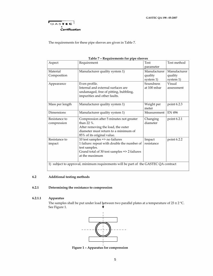
6.2.1.1 Apparatus
The samples shall be put under load between two parallel plates at a temperature of 23 ± 2 ºC. See Figure 1. Figure 1 – Apparatus for compression
GASTEC QA 198 : 05-2007
6
6.2.1.2 Test samples
For each pipe sleeve three test samples with a length of 100 ± 1 mm shall be used.
6.2.1.3 Test method
Gradually subject the test samples to a load of 200 N. Five minutes after having applied the full load, measure the diameter of the test sample along the central line of the direction of the load. Measure the extent of compression as a percentage of the original external diameter. One minute after removing the load determine the external diameter along the direction of load again. Calculate the remaining compression as a percentage of the original external diameter.
6.2.2 Determining the resistance against impact
6.2.2.1 Apparatus
For the test a free-fall testing machine is needed, provided with a falling object with a spherical arm end with a radius of 12.5 mm and a V-shaped supporting block mounted at an angle of 120º. Besides this a cooling trough is needed, in which the test samples can be conditioned at a temperature of 0 ± 1 ºC.
6.2.2.2 Test samples
For each pipe size 10 test samples are needed with a length of 100 mm. The test samples must be brought to a temperature of (0 ± 1) ºC in water or air. For cooling in water, the cooling time is 30 minutes and for cooling in air it is 60 minutes.
6.2.2.3 Working method
Lay the test samples on the V-block and let the falling object drop on the middles of the test samples. Each test sample must be tested within 10 seconds of being taken out of the cooling trough. The test conditions to be met for testing are shown in Table 8.
Table 8 – Test conditions for pipe sleeves
Nominal external diameter of the tube concerned 1)
Mass of falling object (in g, 2)
Drop height in mm
3)
Up to and including 25 mm
250 1000
> 25 mm 250 2000
1) This refers to the tubes that are concerned with the tube sleeves to be tested.
2) Tolerance: - 0/+ 5 g.
3) Tolerance: - 0/+ 5 mm.
6.2.3 Determining the mass per length
For determining this three tube sleeves are needed of a length of approximately 1m. The actual length must be determined as accurately as possible. The mass of these pipes must be determined to an accuracy of 0.1 gram with the aid of a weighing apparatus. The mass per length is taken to be the arithmetic mean value of the quotients of the measured lengths and weights.
GASTEC QA 198 : 05-2007
7
6.2.4 Marking
The tube sleeves shall be marked clearly and permanently at distances of a maximum of 2.5 m with at least the following information.
• GASTEC QA logo
• Inside diameter
• Manufacture name or logo
GASTEC QA 198 : 05-2007
8
A 1. REQUIREMENTS FOR THE QUALITY SYSTEM
A 1.1 General
This section includes the requirements that the producer’s quality system must meet.
A 1.1.1 Quality system manager
There must be an appointed official in the organisation structure who is tasked with the management of the quality system.
A 1.1.2 Internal quality monitoring/quality plan
The producer must be in possession of a plan that he employs for internal quality monitoring, Internal Quality Plan (IKB plan). The following must be demonstrably recorded in the IKB plan: - which aspects are checked by the producer - according to which methods the checks take place - how often the checks are carried out - how the results of the checks are registered and kept. This IKB plan must be a derivative of the model IKB plan shown in the attachment, and be worked out such that it gives Kiwa Gastec sufficient confidence that the requirements laid down in these Assessment Guidelines are continuously met. The IKB plan must correspond to the framework IKB plan included in the attachment.
A 1.1.3 Procedures and work instructions
The certificate holder must have in place: Procedures for:
• dealing with products with defects
• corrective measures for observed faults
• dealing with complaints about products and/or service supplied
• the work instructions and checklists used.
A 1.2 Investigation and check summary
The following is a summary of the checks to be made for certification.
GASTEC QA 198 : 05-2007
9
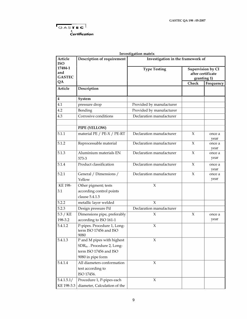
Investigation matrix
Investigation in the framework of
Supervision by CI after certificate granting 1)
Article ISO 17484-1 and GASTEC QA
Description of requirement
Type Testing
Check Frequency
Article Description
4 System
4.1 pressure drop Provided by manufacturer
4.2 Bending Provided by manufacturer
4.3 Corrosive conditions Declaration manufacturer
PIPE (YELLOW)
5.1.1 material PE / PE-X / PE-RT Declaration manufacturer X once a year
5.1.2 Reprocessable material Declaration manufacturer X once a year
5.1.3 Aluminium materials EN
573-3
Declaration manufacturer X once a year
5.1.4 Product classification Declaration manufacturer X once a year
5.2.1 General / Dimensions /
Yellow
Declaration manufacturer X once a year
KE 198-
3.1
Other pigment; tests
according control points
clause 5.4.1.5
X
5.2.2 metallic layer welded X
5.2.3 Design pressure Pd Declaration manufacturer
5.3 / KE
198-3.2
Dimensions pipe, preferably
according to ISO 161-1
X X once a year
5.4.1.2 P-pipes. Procedure 1, Long-term ISO 17456 and ISO 9080
X
5.4.1.3 P and M pipes with highest
SDRm . Procedure 2, Long-
term ISO 17456 and ISO
9080 in pipe form
X
5.4.1.4 All diameters conformation
test according to
ISO 17456.
X
5.4.1.5.1/
KE 198-3.3
Procedure 1, P-pipes each
diameter, Calculation of the
X
GASTEC QA 198 : 05-2007
10
Investigation in the framework of
Supervision by CI after certificate granting 1)
Article ISO 17484-1 and GASTEC QA
Description of requirement
Type Testing
Check Frequency
Article Description
control points according
reference norm for 22h,
165h, 1000h
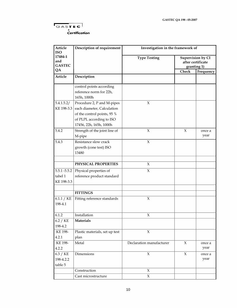
5.4.1.5.2/
KE 198-3.3
Procedure 2, P and M-pipes
each diameter, Calculation
of the control points, 95 %
of PLPL according to ISO
17456, 22h, 165h, 1000h
X
5.4.2 Strength of the joint line of
M-pipe
X X once a year
5.4.3 Resistance slow crack
growth (cone test) ISO
13480
X
PHYSICAL PROPERTIES X
5.5.1 -5.5.2
tabel 1
KE 198-3.3
Physical properties of
reference product standard
X
FITTINGS
6.1.1 / KE
198-4.1
Fitting reference standards X
6.1.2 Installation X
6.2 / KE
198-4.2
Materials
KE 198-
4.2.1
Plastic materials, set up test
plan
X
KE 198-
4.2.2
Metal Declaration manufacturer X once a year
6.3 / KE
198-4.2.2
table 5
Dimensions X X once a year
Construction X
Cast microstructure X
GASTEC QA 198 : 05-2007
11
Investigation in the framework of
Supervision by CI after certificate granting 1)
Article ISO 17484-1 and GASTEC QA
Description of requirement
Type Testing
Check Frequency
Article Description
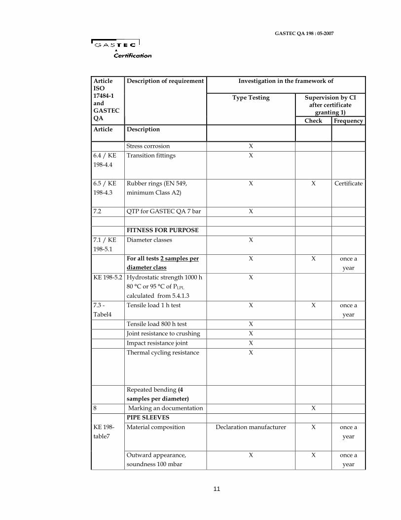
Stress corrosion X
6.4 / KE
198-4.4
Transition fittings X
6.5 / KE
198-4.3
Rubber rings (EN 549,
minimum Class A2)
X X Certificate
7.2 QTP for GASTEC QA 7 bar X
FITNESS FOR PURPOSE
7.1 / KE
198-5.1
Diameter classes X
For all tests 2 samples per
diameter class
X X once a
year
KE 198-5.2 Hydrostatic strength 1000 h
80 °C or 95 °C of PLPL
calculated from 5.4.1.3
X
7.3 -
Tabel4
Tensile load 1 h test X X once a
year
Tensile load 800 h test X
Joint resistance to crushing X
Impact resistance joint X
Thermal cycling resistance X
Repeated bending (4
samples per diameter)
8 Marking an documentation X
PIPE SLEEVES
KE 198-
table7
Material composition Declaration manufacturer X once a
year
Outward appearance,
soundness 100 mbar
X X once a
year
GASTEC QA 198 : 05-2007
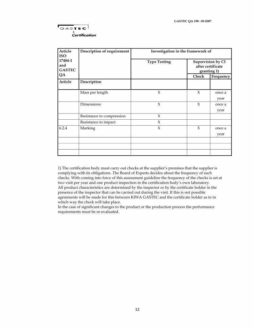
12
Investigation in the framework of
Supervision by CI after certificate granting 1)
Article ISO 17484-1 and GASTEC QA
Description of requirement
Type Testing
Check Frequency
Article Description
Mass per length X X once a
year
Dimensions X X once a
year
Resistance to compression X
Resistance to impact X
6.2.4 Marking X X once a
year
1) The certification body must carry out checks at the supplier’s premises that the supplier is complying with its obligations. The Board of Experts decides about the frequency of such checks. With coming into force of this assessment guideline the frequency of the checks is set at two visit per year and one product inspection in the certification body’s own laboratory. All product characteristics are determined by the inspector or by the certificate holder in the presence of the inspector that can be carried out during the visit. If this is not possible agreements will be made for this between KIWA GASTEC and the certificate holder as to in which way the check will take place. In the case of significant changes to the product or the production process the performance requirements must be re-evaluated.
GASTEC QA 198 : 05-2007
13
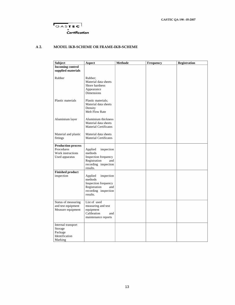
A 2. MODEL IKB-SCHEME OR FRAME-IKB-SCHEME
Subject Aspect Methode Frequency Registration Incoming control supplied materials Rubber Plastic materials Aluminium layer Material and plastic fittings
Rubber; Material data sheets Shore hardness Appearance Dimensions Plastic materials; Material data sheets Density Melt Flow Rate Aluminium thickness Material data sheets Material Certificates Material data sheets Material Certificates
Production process Procedures Work instructions Used apparatus
Applied inspection methods Inspection frequency Registration and recording inspection results.
Finished product inspection
Applied inspection methods Inspection frequency Registration and recording inspection results.
Status of measuring and test equipment Measure equipment
List of used measuring and test equipment Calibration and maintenance reports
Internal transport Storage Package Identification Marking
KE 198-A1 December 2010
GASTEC QA Approval Requirements 198 Amendment A1 Additional requirements regarding plastic fittings for multilayer pipe systems for indoor gas installations with a maximum operating presssure up to and including 5 bar
GASTEC QA Approval Requirements KE 198-A1© Kiwa N.V. - 2 - December 2010
Kiwa Nederland B.V. Wilmersdorf 50 7327 AC Apeldoorn Postbus 137 7300 AC Apeldoorn The Netherlands Tel. +31 55 539 33 93 Fax +31 55 539 34 94 www.kiwa.nl © 2010 Kiwa N.V. All rights reserved. No part of this book may be reproduced, stored in a database or retrieval system, or published, in any form or in any way, electronically, mechanically, by print, photoprint, microfilm or any other means without prior written permission from the publisher. The use of this evaluation guideline by third parties, for any purpose whatsoever, is only allowed after a written agreement is made with Kiwa to this end.
Foreword
This GASTEC QA Approval requirement amendment has been accepted by the Board of Experts Gastec Certification, wherein all the relevant parties in the field of gas related products are represented. These Boards of Experts also supervises the certification activities and where necessary require the GASTEC QA Approval requirement to be revised. All references to Board of Experts in this GASTEC QA Approval requirement pertain to the above mentioned Boards of Experts. This GASTEC QA Approval requirement will be used by Kiwa Nederland BV in conjunction with the Regulations for Product Certification for bearing the GASTEC QA quality label. This regulation details the method employed by Kiwa Nederland BV for conducting the necessary investigations prior to issuing the (technical approval-with) product certificate and the method of external control. The inspection frequency is determined by the above mentioned Boards of Experts. Approved by CvD Gastec Product Certification :09-12-2010 Accepted by Kiwa Nederland BV :09-12-2010
GASTEC QA Approval Requirements KE 198-A1© Kiwa N.V. - 3 - December 2010
Contents
1 Introduction 4 1.1 General 4 1.2 Scope 4 1.3 Acceptance of test reports provided by the supplier 4
2 Product Requirements 5 2.1 General 5
3 Summary of tests and inspections 8 3.1 Test matrix 8 3.2 Evaluation of the quality system 8
GASTEC QA Approval Requirements KE 198-A1© Kiwa N.V. - 4 - December 2010
1 Introduction
1.1 General This supplement is an addition to the current GASTEC QA Approval Requirement 198, multilayer pipe systems for indoor gas installations with a maximum operating presssure up to and including 5 bar, dated May 2007. During the execution of the certification work, Kiwa is bound to the requirements as laid down in the chapter “Agreements on the performance of certification”.
1.2 Scope No approval testing methods are layed down in the current GASTEC QA Approval Requirement 198 regarding the use of plastics fittings, made from Polyvinylidenefluoride (PVDF) material for multilayer pipe systems for indoor gas installations. Therfore, this supplement describes the additional requirements regarding the use of PVDF fittings.
1.3 Acceptance of test reports provided by the supplier The rules for acceptance of test reports provided by the supplier are laid down in the Regulations for Product Certification for bearing the GASTEC QA quality label.
GASTEC QA Approval Requirements KE 198-A1© Kiwa N.V. - 5 - December 2010
2 Product Requirements
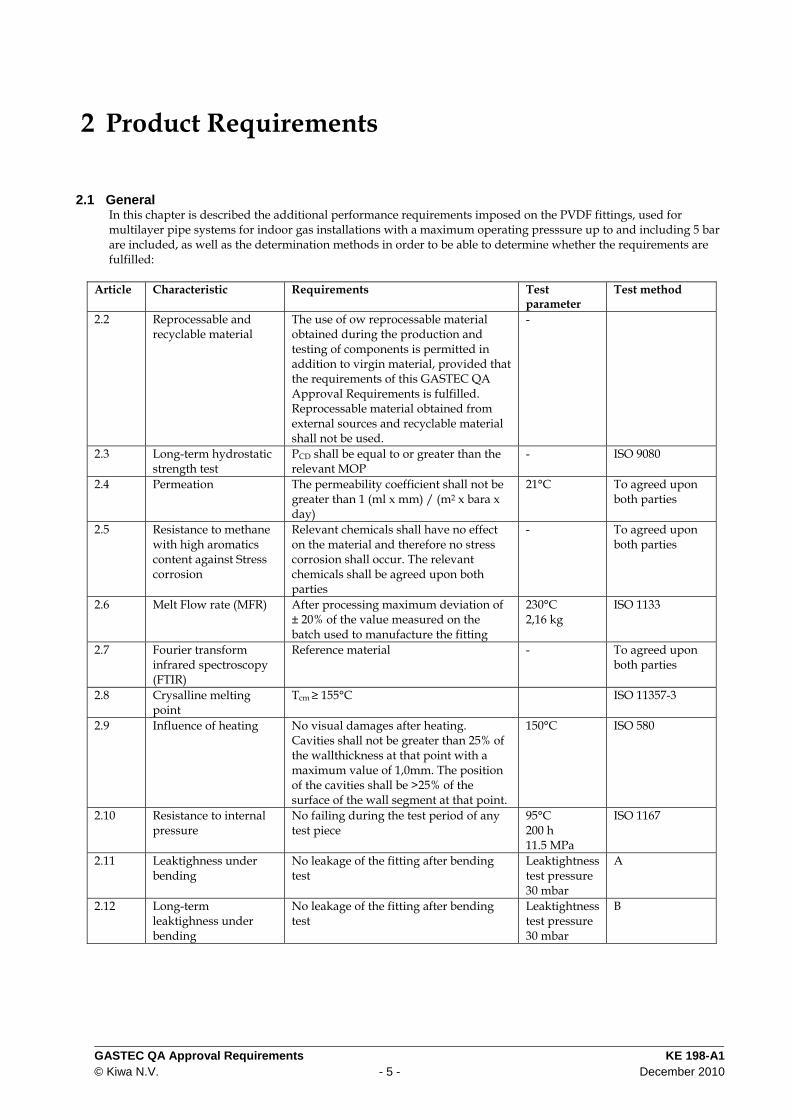
2.1 General In this chapter is described the additional performance requirements imposed on the PVDF fittings, used for multilayer pipe systems for indoor gas installations with a maximum operating presssure up to and including 5 bar are included, as well as the determination methods in order to be able to determine whether the requirements are fulfilled:
Article Characteristic Requirements Test parameter
Test method
2.2 Reprocessable and recyclable material
The use of ow reprocessable material obtained during the production and testing of components is permitted in addition to virgin material, provided that the requirements of this GASTEC QA Approval Requirements is fulfilled. Reprocessable material obtained from external sources and recyclable material shall not be used.
-
2.3 Long-term hydrostatic strength test
PCD shall be equal to or greater than the relevant MOP
- ISO 9080
2.4 Permeation The permeability coefficient shall not be greater than 1 (ml x mm) / (m2 x bara x day)
21°C To agreed upon both parties
2.5 Resistance to methane with high aromatics content against Stress corrosion
Relevant chemicals shall have no effect on the material and therefore no stress corrosion shall occur. The relevant chemicals shall be agreed upon both parties
- To agreed upon both parties
2.6 Melt Flow rate (MFR) After processing maximum deviation of ± 20% of the value measured on the batch used to manufacture the fitting
230°C 2,16 kg
ISO 1133
2.7 Fourier transform infrared spectroscopy (FTIR)
Reference material - To agreed upon both parties
2.8 Crysalline melting point
Tcm ≥ 155°C ISO 11357-3
2.9 Influence of heating No visual damages after heating. Cavities shall not be greater than 25% of the wallthickness at that point with a maximum value of 1,0mm. The position of the cavities shall be >25% of the surface of the wall segment at that point.
150°C
ISO 580
2.10 Resistance to internal pressure
No failing during the test period of any test piece
95°C 200 h 11.5 MPa
ISO 1167
2.11 Leaktighness under bending
No leakage of the fitting after bending test
Leaktightness test pressure 30 mbar
A
2.12 Long-term leaktighness under bending
No leakage of the fitting after bending test
Leaktightness test pressure 30 mbar
B
GASTEC QA Approval Requirements KE 198-A1© Kiwa N.V. - 6 - December 2010
3 Test methods
3.1 Method A
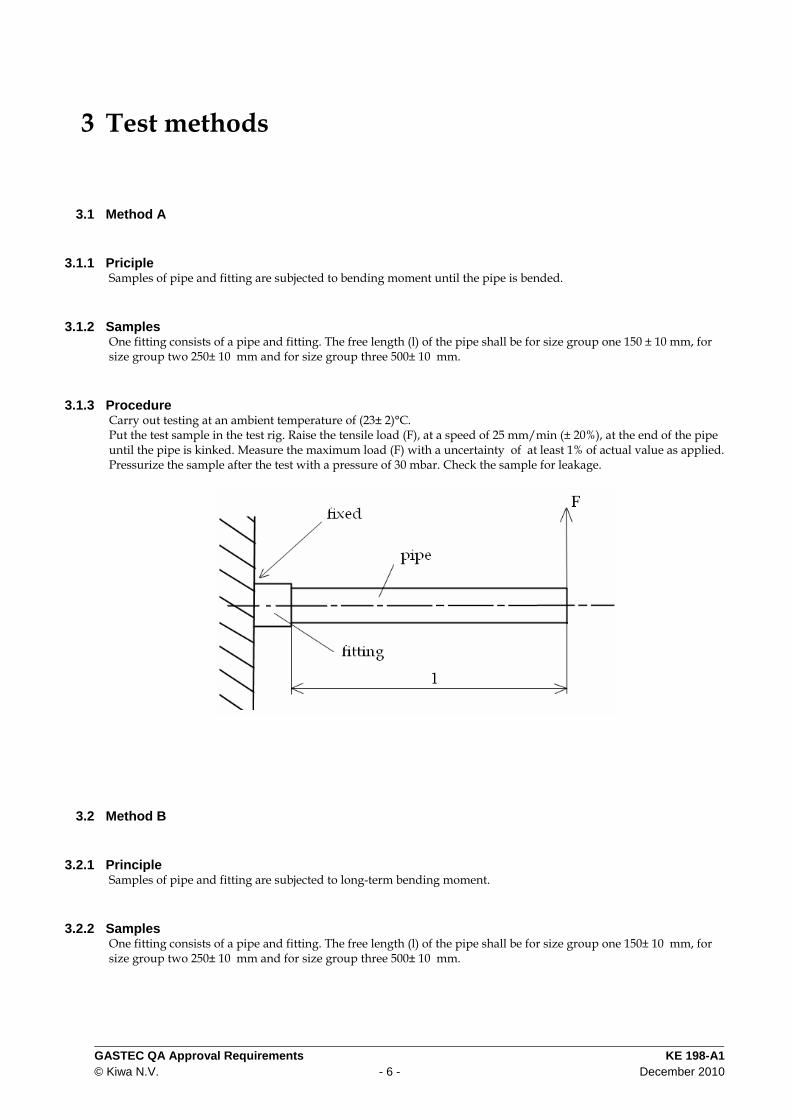
3.1.1 Priciple Samples of pipe and fitting are subjected to bending moment until the pipe is bended.
3.1.2 Samples One fitting consists of a pipe and fitting. The free length (l) of the pipe shall be for size group one 150 ± 10 mm, for size group two 250± 10 mm and for size group three 500± 10 mm.
3.1.3 Procedure Carry out testing at an ambient temperature of (23± 2)°C. Put the test sample in the test rig. Raise the tensile load (F), at a speed of 25 mm/min (± 20%), at the end of the pipe until the pipe is kinked. Measure the maximum load (F) with a uncertainty of at least 1% of actual value as applied. Pressurize the sample after the test with a pressure of 30 mbar. Check the sample for leakage.
3.2 Method B
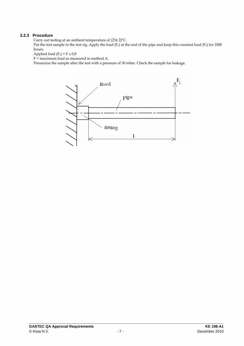
3.2.1 Principle Samples of pipe and fitting are subjected to long-term bending moment.
3.2.2 Samples One fitting consists of a pipe and fitting. The free length (l) of the pipe shall be for size group one 150± 10 mm, for size group two 250± 10 mm and for size group three 500± 10 mm.
GASTEC QA Approval Requirements KE 198-A1© Kiwa N.V. - 7 - December 2010
3.2.3 Procedure Carry out testing at an ambient temperature of (23± 2)°C. Put the test sample in the test rig. Apply the load (F1) at the end of the pipe and keep this constant load (F1) for 1000 hours. Applied load (F1) = F x 0,8 F = maximum load as measured in method A. Pressurize the sample after the test with a pressure of 30 mbar. Check the sample for leakage.
GASTEC QA Approval Requirements KE 198-A1© Kiwa N.V. - 8 - December 2010
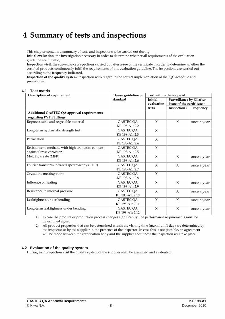
4 Summary of tests and inspections
This chapter contains a summary of tests and inspections to be carried out during: Initial evaluation: the investigation necessary in order to determine whether all requirements of the evaluation guideline are fulfilled, Inspection visit: the surveillance inspections carried out after issue of the certificate in order to determine whether the certified products continuously fulfil the requirements of this evaluation guideline. The inspections are carried out according to the frequency indicated. Inspection of the quality system: inspection with regard to the correct implementation of the IQC-schedule and procedures.
4.1 Test matrix Test within the scope of
Surveillance by CI after issue of the certificate1)
Description of requirement Clause guideline or standard Initial
evaluation tests Inspection2) Frequency
Additional GASTEC QA approval requirements regarding PVDF fittings
Reprocessable and recyclable material GASTEC QA KE 198-A1: 2.2
X X once a year
Long-term hydrostatic strength test GASTEC QA KE 198-A1: 2.3
X
Permeation GASTEC QA KE 198-A1: 2.4
X
Resistance to methane with high aromatics content against Stress corrosion
GASTEC QA KE 198-A1: 2.5
X
Melt Flow rate (MFR) GASTEC QA KE 198-A1: 2.6
X X once a year
Fourier transform infrared spectroscopy (FTIR) GASTEC QA KE 198-A1: 2.7
X X once a year
Crysalline melting point GASTEC QA KE 198-A1: 2.8
X
Influence of heating GASTEC QA KE 198-A1: 2.9
X X once a year
Resistance to internal pressure GASTEC QA KE 198-A1: 2.10
X X once a year
Leaktighness under bending GASTEC QA KE 198-A1: 2.11
X X once a year
Long-term leaktighness under bending GASTEC QA KE 198-A1: 2.12
X X once a year
1) In case the product or production process changes significantly, the performance requirements must be determined again.
2) All product properties that can be determined within the visiting time (maximum 1 day) are determined by the inspector or by the supplier in the presence of the inspector. In case this is not possible, an agreement will be made between the certification body and the supplier about how the inspection will take place.
4.2 Evaluation of the quality system During each inspection visit the quality system of the supplier shall be examined and evaluated.
![KE 208 GASTEC QA May 2016 - Service Portal Kiwa · These GASTEC QA Approval requirements have been approved by the Board of Experts product ... [see EN ISO 6708] GASTEC QA Approval](https://img.pdfslide.net/doc/110x75/5ba0d3ef09d3f259468d7c4e/ke-208-gastec-qa-may-2016-service-portal-kiwa-these-gastec-qa-approval-requirements.jpg)
![INDEX [metalagencies.com] · EN 1057 Quality Marks BSI, AFNOR, NSAI, AENOR, RAL / DVGW, KIWA / GASTEC-QA, SITAC, STF VTT, GOST, VIK. Mechanical Properties 06 • WATER SUPPLY •](https://img.pdfslide.net/doc/110x75/5f0ad1247e708231d42d7c8a/index-en-1057-quality-marks-bsi-afnor-nsai-aenor-ral-dvgw-kiwa-gastec-qa.jpg)