Embed Size (px)
Citation preview

Institute for Thermal Turbomaschinery and Machine Dynamics
Graz University of TechnologyErzherzog-Johann-University
Gasturbine with CO2 Retention –400 MW Oxyfuel-System Graz Cycle
Herbert Jericha, Wolfgang Sanz and Emil GöttlichInstitute for Thermal Turbomachinery and Machine Dynamics
Graz University of TechnologyAustria
25th CIMAC CongressMay, 21-24, 2007, in Vienna

Background
• Toronto Conference 1988, a Call for Action• Kyoto Protocol demands the reduction of greenhouse
gases, mainly CO2• In EU: strong pressure on utilities and companies to
reduce CO2 emissions• In 2005: emission allowances to about 10 000 companies
within the EU covering about 46 % of the overall EU CO2 emissions
• As emission allowances become scarce: CO2 generates costs (European Emission Allowances Trading)
• CO2 and N2 from ASU can be utilized for Enhanced Oil Recovery (EOR)Return: 20 – 40 $/ton CO2

Oxy-Fuel Cycles
• Oxy-fuel cycles with internal combustion with pure oxygen are a very promising technology(Global Gas Turbine News 10/2005)
+ CO2 can be easily separated by condensation fromworking fluid consisting of CO2 and H2O, no need for very penalizing scrubbing
+ Very low NOx generation (fuel bound N2)
+ Flexibility regarding fuel: high CO2 content natural gas, syngas from coal, biomass or refinery res. gasification
- New equipment required
- Additional high costs of oxygen production
+ These new cycles show higher efficiencies than currentair-based combined cycles (Graz Cycle, Matiant cycle,Water cycle,...)

History of the Graz Cycle
• 1985: presentation of a power cycle without any emission (CIMAC Oslo)• H2/O2 internally fired steam cycle, as integration of top Brayton
steam cycle and bottom Rankine cycle • efficiency 6 % - points higher than state-of-the art CC plants
• 1995: Graz cycle adopted for the combustion of fossil fuels like methane (CH4) (CIMAC Interlaken & ASME Cogen Vienna)• cycle fluid is a mixture of H2O and CO2• thermal cycle efficiency: 64 %
• 2000: thermodynamically optimized cycle for syngas from coal gasification (VDI Essen – in German)
• 2002/2003: conceptual layout of prototype Graz Cycle power plant: detailed design of components (ASME Amsterdam, VDI Leverkusen, ASME Best Paper Award in Atlanta)
• 2004/2005: presentation of S-Graz Cycle with 69% thermal efficiency and 57 % net efficiency for syngas firing (ASME Vienna, ASME Reno)

Cycle Scheme (ASME 2006)
Cycle Fluid
79 % H2O21 % CO2
H2O
CO2
water
C4
1.95 bar
C3
1.27 bar
0.75 bar
LPST Condenser
175 °C 0.021 bar180 bar550°C
HPT
Deaerator
C1/C2
580°C
Fuel(methane)
O2Combustor
steam
40 bar
HTT1400°C
HRSG
1bar573°C
180°C
water injectionfor cooling
Compressors C3 and C4 raisepartial steam pressure for condensation and deliver CO2

Graz Cycle Power Balance
HTT Power [MW] 617.9 Net Shaft Power withoutMechanical Losses [MW]
504.7
HPT Power[MW] 49.9 Total Heat Input [MW] 758.6
LPST Power[MW] 71.6 Thermal Cycle Efficiency [%] 66.52
Total Turbine Power [MW] 739.4 Elektric Power incl. all Additional Losses [MW]
490.7
C1 Power[MW] 131.1 Net Electrical Cycle Efficiency [%]
64.68
C2 Power[MW] 82.6 O2 Generation & CompressionPO2 [MW]
74.7
C3 Power[MW] 8.9 Efficiency considering O2 Supply [%]
54.83
C4 Power[MW] 6.6 CO2 Compression to 100 bar PCO2 [MW]
13.0
Total Pump Power [MW] 5.5 Net Power Output [MW] 403.0
Total Compressor Power [MW]
234.7 Net Efficiency incl. Environm. Obligations [%]
53.12
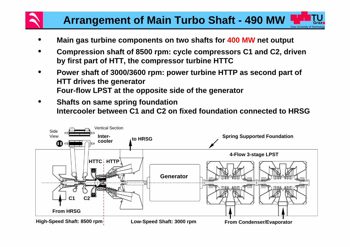
Arrangement of Main Turbo Shaft - 490 MW
• Main gas turbine components on two shafts for 400 MW net output• Compression shaft of 8500 rpm: cycle compressors C1 and C2, driven
by first part of HTT, the compressor turbine HTTC• Power shaft of 3000/3600 rpm: power turbine HTTP as second part of
HTT drives the generatorFour-flow LPST at the opposite side of the generator
• Shafts on same spring foundationIntercooler between C1 and C2 on fixed foundation connected to HRSG
SideView
Vertical Section
Inter-cooler
From HRSG
to HRSG
Generator
4-Flow 3-stage LPST
From Condenser/Evaporator
C2C1
High-Speed Shaft: 8500 rpm Low-Speed Shaft: 3000 rpm
HTTP
Spring Supported Foundation
HTTC

High Speed Shaft (8500 rpm)
• Compressors C1 und C2 for working fluid (79% H2O/ 21 % CO2) and HTTC
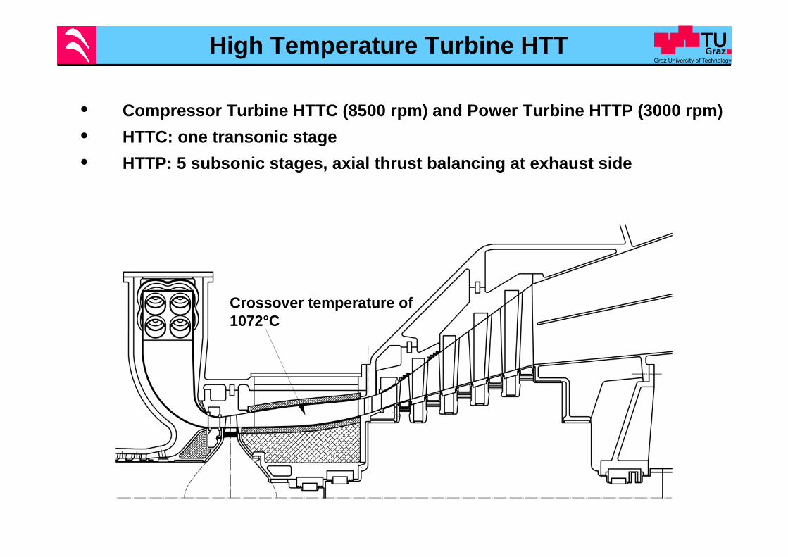
High Temperature Turbine HTT
• Compressor Turbine HTTC (8500 rpm) and Power Turbine HTTP (3000 rpm)• HTTC: one transonic stage• HTTP: 5 subsonic stages, axial thrust balancing at exhaust side
Crossover temperature of 1072°C

Steam Cooling Details of HTTC and C2
• HTTC and C2 on common shaft with a disk of constant stress• Disk is cooled on both sides with cooling steam of 300°C• Cooling steam on right-hand-side: balancing of axial thrust• C2 rotor: cooling to avoid creep
Steam Injection for Improvement of Meridional Flow Profile
Cooling steam

Combustion Chamber• Design as presented at ASME 2003,
scaled up from 75 to 400 net power
• Stoichiometric combustion of fossil fuel and O2 at 40 bar
• Combustor exit temperature: 1400 °C
• Oxidizer is not cooling medium, thus risk of incomplete combustion. So fuel and O2 inflow have to be kept in close contact in burner vortex
• Cooling of burner by steam wrapping around burner head, limits flame temperature and prevents acoustic vibrations excitation
• Annular flame casing with 6 quadruples of burner tubes
• Cooling of annular flame cage by recompressed working fluid flow
• Tangential arrangement provides additional flow path length for better mixture and pre-swirl for first turbine stage

Stress of C2-HTTC shaft
• Analytic solutions for three-dimensional stress• Rotor cooled to 300°C
Rotationally symmetric stress distribution
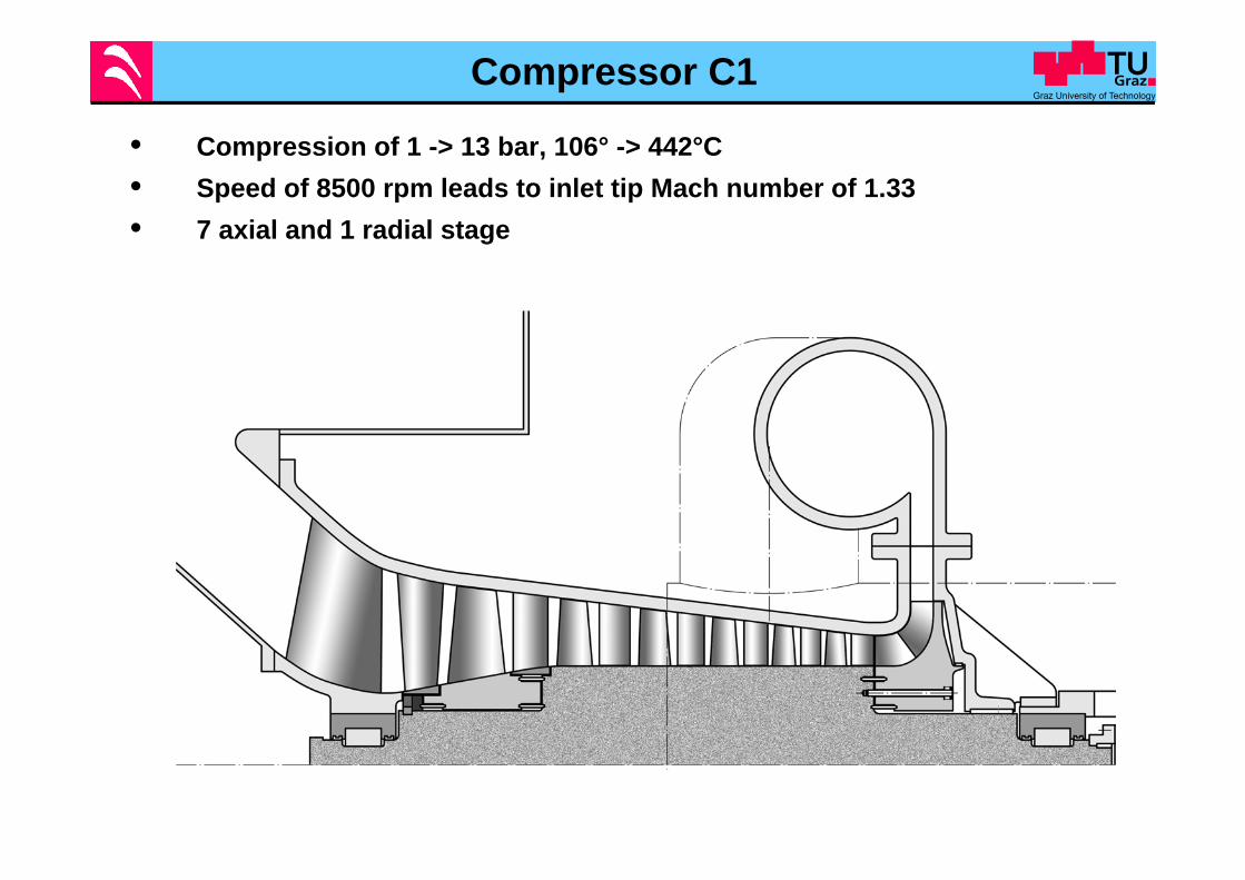
Compressor C1
• Compression of 1 -> 13 bar, 106° -> 442°C • Speed of 8500 rpm leads to inlet tip Mach number of 1.33• 7 axial and 1 radial stage

Details of Compressor C1
• First axial stage: titanium blisk to reduce centrifuga load• Last stage: radial wheel of nickel based alloy• Elastic centering rings allowing radial deformation

Use of Double-Wedge Bearings• Double-wedge bearing: Patent Elin 1963• Space of rotor movement inside the two fixed circular bearing halves
(rotor reduced to its centre point in this diagram); • Bearing properties: close centring of rotor allow to withstand even
very high lateral forces; • Diagram of Sommerfeld number vs. pin movement shows high
damping and high elasticity of oil films.
Rotor weight
Orbit of pin center at large rotor unbalance
Possible rotor positions So,damping
So,static
Pin velocity=0.1ω∆R

Rotor Dynamics of C1
• 1st Eigenfrequency: 0.622 x 8500 rpm, 2nd Eigenfrequency: 16 790 rpm• Self centering of shaft leads to small bearing loads and small vibrational
amplitudes
1. EF
2. EF

C1 Shaft at High Unbalancing Force
• High amplitude at location of unbalance force• Centering by double-wedge bearings results in acceptable amplitudes in
other stages
Static Bearing Force
Static Bearing Force
Rotating Unbalance
Rotating BearingForce
Rotating Bearing Force
SpinningVector

Conclusions
• Graz Cylce is an oxy-fuel power cycle of highest efficiency for CO2 retention
• Turbomachinery design for a system of 400 MW net power output has been presented and design details are discussed
• Detailed deliberations on material selection, stresses and rotordynamics as well as bearing design are given
• We hope that our work will help industry to achieve a successful result in manufacture and operation in the short time limits indicated by European ZEP initiative.