Embed Size (px)
Citation preview
GATE
VALV
ES
SAMAMAT FLOW CONTROL L.L.C.
GATE
VALV
ES
SAMAMAT FLOW CONTROL L.L.C.
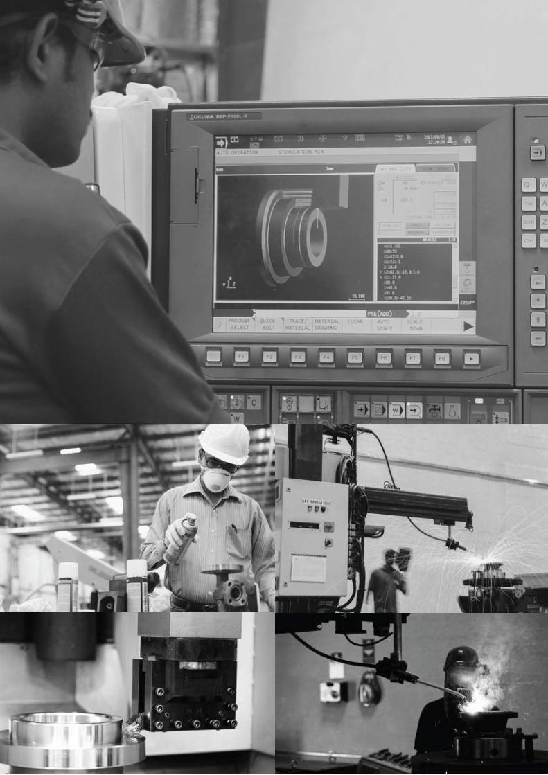
Samamat Flow Control L.L.C. is a UAE-based Valve-Manufacturing and Valve-Servicing Company for the process, power, and energy-related industries. Samamat has state-of-the-art manufacturing facility, producing high-quality valves to meet speci�c requirements of both local and international clients. This modern facility is supported by a specialized team of highly-skilled, ingenious technicians who ensure that the valves consistently deliver high performance and adherence to international standards.
Samamat has been specially organized to meet client requirements through an in-house testing facility of MT, PT, UT, Hardness, Chemical Analysis and PMI, in line with Machining, Assembling, Testing, Inspection, Welding and Packing. The facility is situated in Dubai Investment Park, Dubai, UAE.
Samamat also excels in delivering outstanding services to its customers. All team members are trained to work in a SMART, dedicated and timely basis to ensure that they keep their promise to stakeholders like customers, colleagues, suppliers, regulators, �nanciers, and shareholders.
MissionTo o�er a wide range of products and specialized services for Valves and Flanges while ensuring that the customer’s needs are met on time and according to speci�cations.
VisionTo become a global leader in providing innovative products and services for the Flow-Control industry, creating value in order to meet customer expectations in terms of quality, reliability and customer service.
ValuesIntegrity | Building RelationshipsOwnership & Commitment | Teamwork | Customer Focus
Quality PolicyIt is the policy of Samamat Flow Control to achieve rapid and continual improvement in performance to ensure that Design, Development and Manufacturing of all product of Samamat Flow Control meet or exceed API/PED design speci�cations and customer requirements.
www.samamatuae.com
ABOUT US
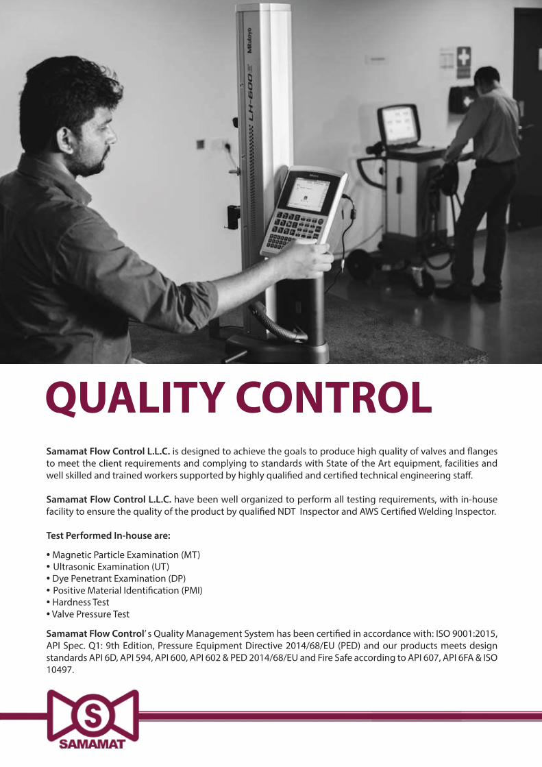
QUALITY CONTROLSamamat Flow Control L.L.C. is designed to achieve the goals to produce high quality of valves and �anges to meet the client requirements and complying to standards with State of the Art equipment, facilities and well skilled and trained workers supported by highly quali�ed and certi�ed technical engineering sta�.
Samamat Flow Control L.L.C. have been well organized to perform all testing requirements, with in-house facility to ensure the quality of the product by quali�ed NDT Inspector and AWS Certi�ed Welding Inspector.
Test Performed In-house are:
• Magnetic Particle Examination (MT)• Ultrasonic Examination (UT)• Dye Penetrant Examination (DP)• Positive Material Identi�cation (PMI)• Hardness Test• Valve Pressure Test
Samamat Flow Control’ s Quality Management System has been certi�ed in accordance with: ISO 9001:2015, API Spec. Q1: 9th Edition, Pressure Equipment Directive 2014/68/EU (PED) and our products meets design standards API 6D, API 594, API 600, API 602 & PED 2014/68/EU and Fire Safe according to API 607, API 6FA & ISO 10497.
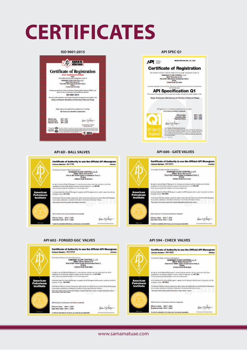
ISO 9001:2015
API 6D - BALL VALVES
API SPEC Q1
API 600 - GATE VALVES
API 602 - FORGED GGC VALVES API 594 - CHECK VALVES
CERTIFICATES
www.samamatuae.com
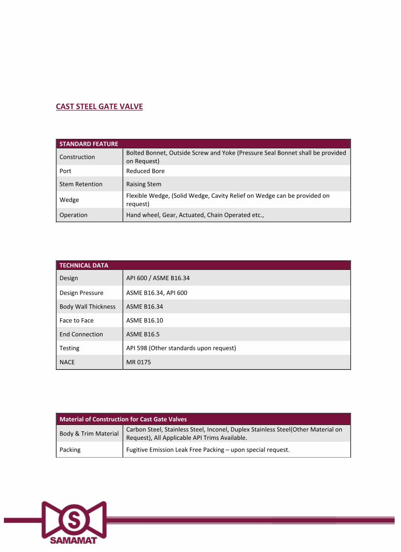
CAST STEEL GATE VALVE
STANDARD FEATURE
Construction Bolted Bonnet, Outside Screw and Yoke (Pressure Seal Bonnet shall be providedon Request)
Port Reduced Bore
Stem Retention Raising Stem
Wedge Flexible Wedge, (Solid Wedge, Cavity Relief on Wedge can be provided onrequest)
Operation Hand wheel, Gear, Actuated, Chain Operated etc.,
TECHNICAL DATA
Design API 600 / ASME B16.34
Design Pressure ASME B16.34, API 600
Body Wall Thickness ASME B16.34
Face to Face ASME B16.10
End Connection ASME B16.5
Testing API 598 (Other standards upon request)
NACE MR 0175
Material of Construction for Cast Gate Valves
Body & Trim Material Carbon Steel, Stainless Steel, Inconel, Duplex Stainless Steel(Other Material onRequest), All Applicable API Trims Available.
Packing Fugitive Emission Leak Free Packing – upon special request.
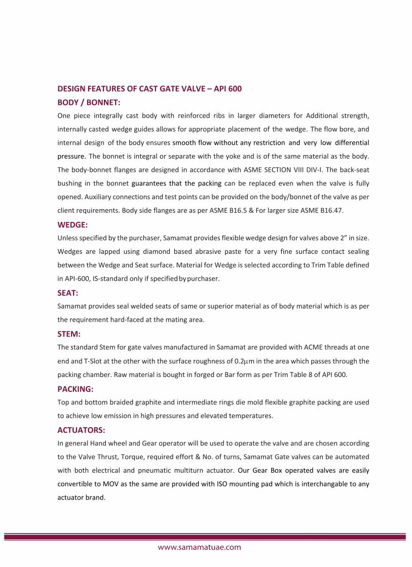
DESIGN FEATURES OF CAST GATE VALVE – API 600BODY / BONNET:One piece integrally cast body with reinforced ribs in larger diameters for Additional strength,
internally casted wedge guides allows for appropriate placement of the wedge. The flow bore, and
internal design of the body ensures smooth flow without any restriction and very low differential
pressure. The bonnet is integral or separate with the yoke and is of the same material as the body.
The body bonnet flanges are designed in accordance with ASME SECTION VIII DIV I. The back seat
bushing in the bonnet guarantees that the packing can be replaced even when the valve is fully
opened. Auxiliary connections and test points can be provided on the body/bonnet of the valve as per
client requirements. Body side flanges are as per ASME B16.5 & For larger size ASME B16.47.
WEDGE:Unless specified by the purchaser, Samamat provides flexible wedge design for valves above 2” in size.
Wedges are lapped using diamond based abrasive paste for a very fine surface contact sealing
between the Wedge and Seat surface. Material for Wedge is selected according to Trim Table defined
in API 600, IS standard only if specifiedbypurchaser.
SEAT:Samamat provides seal welded seats of same or superior material as of body material which is as per
the requirement hard faced at the mating area.
STEM:The standard Stem for gate valves manufactured in Samamat are provided with ACME threads at one
end and T Slot at the other with the surface roughness of 0.2 m in the area which passes through the
packing chamber. Raw material is bought in forged or Bar form as per Trim Table 8 of API 600.
PACKING:Top and bottom braided graphite and intermediate rings die mold flexible graphite packing are used
to achieve low emission in high pressures and elevated temperatures.
ACTUATORS:In general Hand wheel and Gear operator will be used to operate the valve and are chosen according
to the Valve Thrust, Torque, required effort & No. of turns, Samamat Gate valves can be automated
with both electrical and pneumatic multiturn actuator. Our Gear Box operated valves are easily
convertible to MOV as the same are provided with ISO mounting pad which is interchangable to any
actuator brand.
www.samamatuae.com
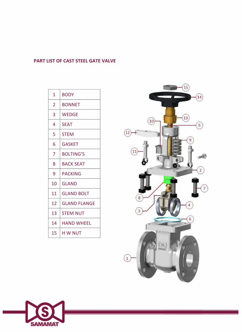
PART LIST OF CAST STEEL GATE VALVE
1 BODY
2 BONNET
3 WEDGE
4 SEAT
5 STEM
6 GASKET
7 BOLTING’S
8 BACK SEAT
9 PACKING
10 GLAND
11 GLAND BOLT
12 GLAND FLANGE
13 STEM NUT
14 HANDWHEEL
15 H W NUT
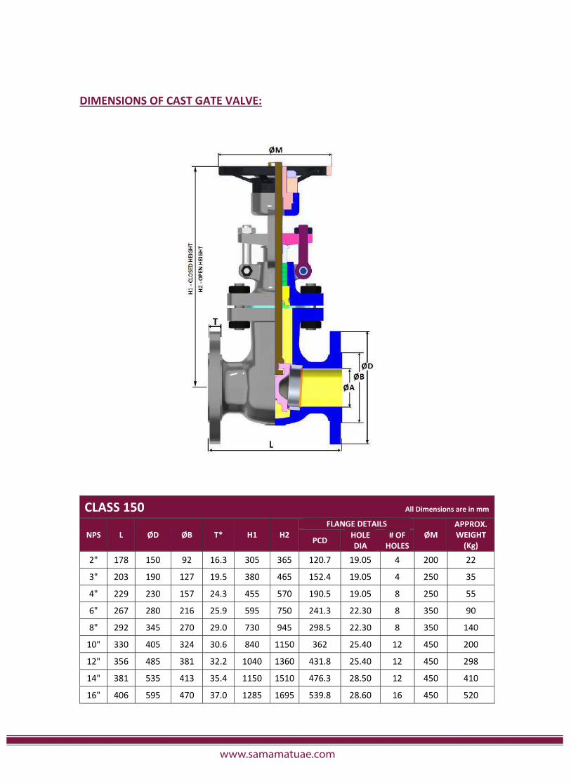
DIMENSIONS OF CAST GATE VALVE:
CLASS 150 All Dimensions are in mm
NPS L ØD ØB T* H1 H2FLANGE DETAILS
ØMAPPROX.WEIGHT(Kg)PCD HOLE
DIA# OFHOLES
2" 178 150 92 16.3 305 365 120.7 19.05 4 200 22
3" 203 190 127 19.5 380 465 152.4 19.05 4 250 35
4" 229 230 157 24.3 455 570 190.5 19.05 8 250 55
6" 267 280 216 25.9 595 750 241.3 22.30 8 350 90
8" 292 345 270 29.0 730 945 298.5 22.30 8 350 140
10" 330 405 324 30.6 840 1150 362 25.40 12 450 200
12" 356 485 381 32.2 1040 1360 431.8 25.40 12 450 298
14" 381 535 413 35.4 1150 1510 476.3 28.50 12 450 410
16" 406 595 470 37.0 1285 1695 539.8 28.60 16 450 520
www.samamatuae.com
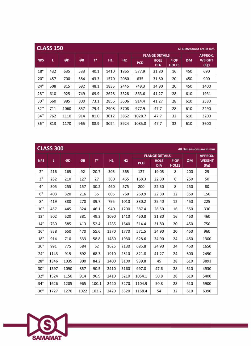
CLASS 300 All Dimensions are in mm
NPS L ØD ØB T* H1 H2FLANGE DETAILS
ØMAPPROX.WEIGHT(Kg)PCD HOLE
DIA# OFHOLES
2" 216 165 92 20.7 305 365 127 19.05 8 200 25
3" 282 210 127 27 380 465 168.3 22.30 8 250 50
4" 305 255 157 30.2 460 575 200 22.30 8 250 80
6" 403 320 216 35 605 760 269.9 22.30 12 350 150
8" 419 380 270 39.7 795 1010 330.2 25.40 12 450 225
10" 457 445 324 46.1 940 1200 387.4 28.50 16 550 330
12" 502 520 381 49.3 1090 1410 450.8 31.80 16 450 460
14" 760 585 413 52.4 1285 1640 514.4 31.80 20 450 750
16" 838 650 470 55.6 1370 1770 571.5 34.90 20 450 960
18" 914 710 533 58.8 1480 1930 628.6 34.90 24 450 1300
20" 991 775 584 62 1625 2130 685.8 34.90 24 450 1650
24" 1143 915 692 68.3 1910 2510 821.8 41.27 24 600 2450
28’’ 1346 1035 800 84.2 2400 3100 939.8 45 28 610 3893
30’’ 1397 1090 857 90.5 2410 3160 997.0 47.6 28 610 4930
32’’ 1524 1150 914 96.9 2410 3210 1054.1 50.8 28 610 5400
34’’ 1626 1205 965 100.1 2420 3270 1104.9 50.8 28 610 5900
36’’ 1727 1270 1022 103.2 2420 3320 1168.4 54 32 610 6390
CLASS 150 All Dimensions are in mm
NPS L ØD ØB T* H1 H2FLANGE DETAILS
ØMAPPROX.WEIGHT(Kg)PCD HOLE
DIA# OFHOLES
18" 432 635 533 40.1 1410 1865 577.9 31.80 16 450 690
20" 457 700 584 43.3 1570 2080 635 31.80 20 450 900
24" 508 815 692 48.1 1835 2445 749.3 34.90 20 450 1400
28’’ 610 925 749 69.9 2628 3328 863.6 41.27 28 610 1931
30’’ 660 985 800 73.1 2856 3606 914.4 41.27 28 610 2380
32’’ 711 1060 857 79.4 2908 3708 977.9 47.7 28 610 2490
34’’ 762 1110 914 81.0 3012 3862 1028.7 47.7 32 610 3200
36’’ 813 1170 965 88.9 3024 3924 1085.8 47.7 32 610 3600
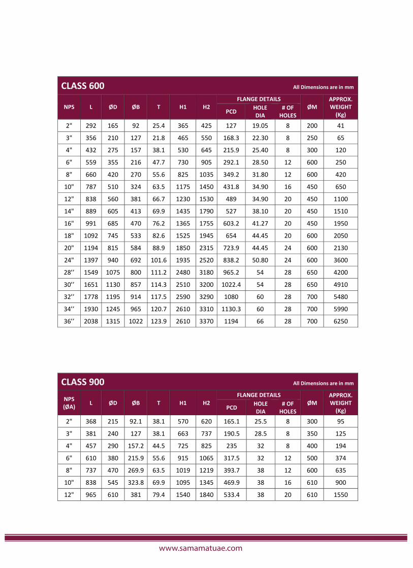
CLASS 600 All Dimensions are in mm
NPS L ØD ØB T H1 H2FLANGE DETAILS
ØMAPPROX.WEIGHT(Kg)PCD HOLE
DIA# OFHOLES
2" 292 165 92 25.4 365 425 127 19.05 8 200 41
3" 356 210 127 21.8 465 550 168.3 22.30 8 250 65
4" 432 275 157 38.1 530 645 215.9 25.40 8 300 120
6" 559 355 216 47.7 730 905 292.1 28.50 12 600 250
8" 660 420 270 55.6 825 1035 349.2 31.80 12 600 420
10" 787 510 324 63.5 1175 1450 431.8 34.90 16 450 650
12" 838 560 381 66.7 1230 1530 489 34.90 20 450 1100
14" 889 605 413 69.9 1435 1790 527 38.10 20 450 1510
16" 991 685 470 76.2 1365 1755 603.2 41.27 20 450 1950
18" 1092 745 533 82.6 1525 1945 654 44.45 20 600 2050
20" 1194 815 584 88.9 1850 2315 723.9 44.45 24 600 2130
24" 1397 940 692 101.6 1935 2520 838.2 50.80 24 600 3600
28’’ 1549 1075 800 111.2 2480 3180 965.2 54 28 650 4200
30’’ 1651 1130 857 114.3 2510 3200 1022.4 54 28 650 4910
32’’ 1778 1195 914 117.5 2590 3290 1080 60 28 700 5480
34’’ 1930 1245 965 120.7 2610 3310 1130.3 60 28 700 5990
36’’ 2038 1315 1022 123.9 2610 3370 1194 66 28 700 6250
CLAS 900 All Dimensions are in m
CLASS 900 All Dimensions are in mm
NPS(ØA) L ØD ØB T H1 H2
FLANGE DETAILSØM
APPROX.WEIGHT(Kg)PCD HOLE
DIA# OFHOLES
2" 368 215 92.1 38.1 570 620 165.1 25.5 8 300 95
3" 381 240 127 38.1 663 737 190.5 28.5 8 350 125
4" 457 290 157.2 44.5 725 825 235 32 8 400 194
6" 610 380 215.9 55.6 915 1065 317.5 32 12 500 374
8" 737 470 269.9 63.5 1019 1219 393.7 38 12 600 635
10" 838 545 323.8 69.9 1095 1345 469.9 38 16 610 900
12" 965 610 381 79.4 1540 1840 533.4 38 20 610 1550
www.samamatuae.com
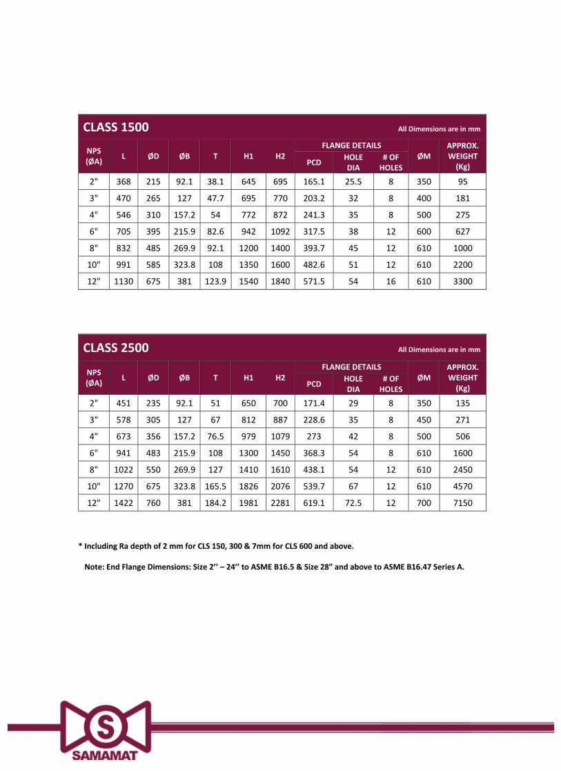
CLASS 1500 All Dimensions are in mm
NPS(ØA) L ØD ØB T H1 H2
FLANGE DETAILSØM
APPROX.WEIGHT(Kg)PCD HOLE
DIA# OFHOLES
2" 368 215 92.1 38.1 645 695 165.1 25.5 8 350 95
3" 470 265 127 47.7 695 770 203.2 32 8 400 181
4" 546 310 157.2 54 772 872 241.3 35 8 500 275
6" 705 395 215.9 82.6 942 1092 317.5 38 12 600 627
8" 832 485 269.9 92.1 1200 1400 393.7 45 12 610 1000
10" 991 585 323.8 108 1350 1600 482.6 51 12 610 2200
12" 1130 675 381 123.9 1540 1840 571.5 54 16 610 3300
CLASS 2500 All Dimensions are in mm
NPS(ØA) L ØD ØB T H1 H2
FLANGE DETAILSØM
APPROX.WEIGHT(Kg)PCD HOLE
DIA# OFHOLES
2" 451 235 92.1 51 650 700 171.4 29 8 350 135
3" 578 305 127 67 812 887 228.6 35 8 450 271
4" 673 356 157.2 76.5 979 1079 273 42 8 500 506
6" 941 483 215.9 108 1300 1450 368.3 54 8 610 1600
8" 1022 550 269.9 127 1410 1610 438.1 54 12 610 2450
10" 1270 675 323.8 165.5 1826 2076 539.7 67 12 610 4570
12" 1422 760 381 184.2 1981 2281 619.1 72.5 12 700 7150
* Including Ra depth of 2 mm for CLS 150, 300 & 7mm for CLS 600 and above.
End Flange Dimensions: Size 2’’ – 24’’ to ASME B16.5 & Size 28” and above to ASME B16.47 Series A.
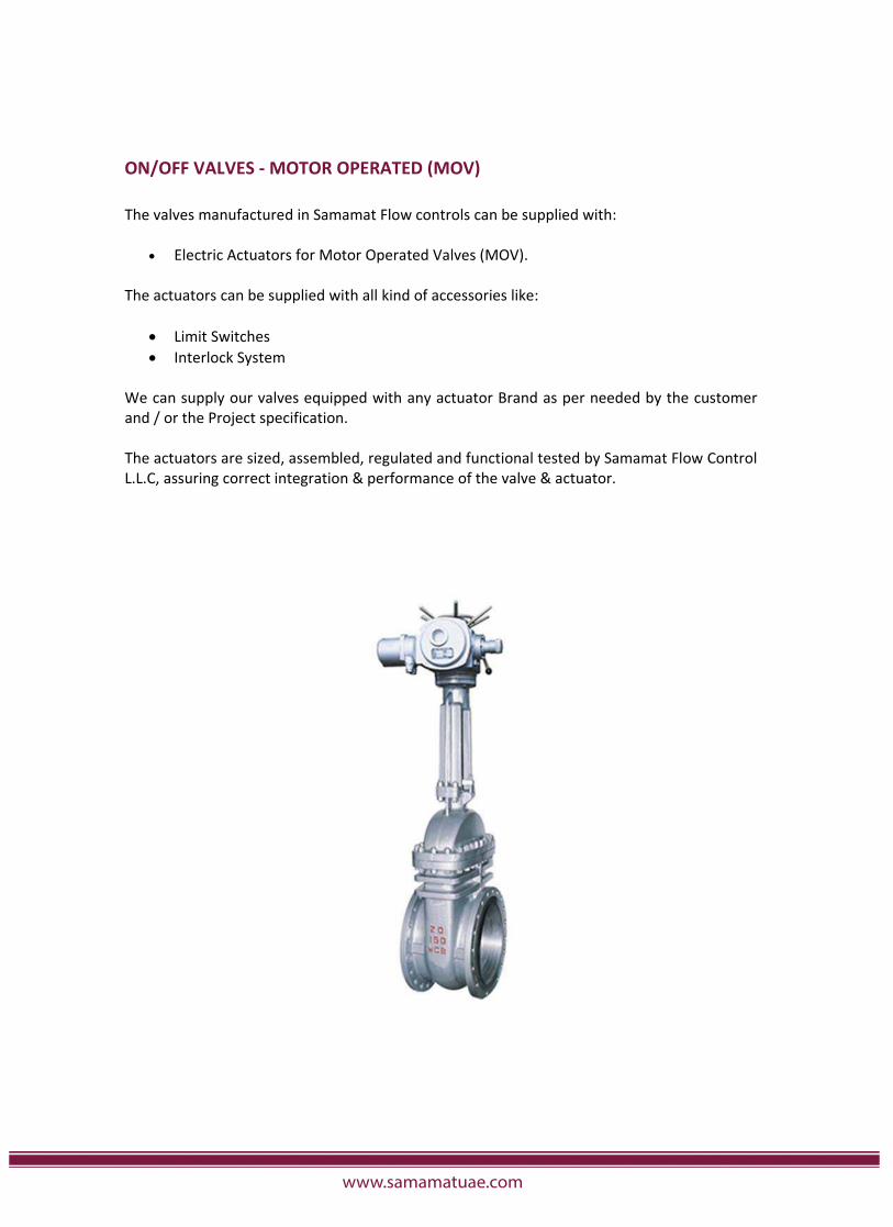
ON/OFF VALVES MOTOR OPERATED (MOV)
The valves manufactured in Samamat Flow controls can be supplied with:
Electric Actuators for Motor Operated Valves (MOV).
The actuators can be supplied with all kind of accessories like:
Limit SwitchesInterlock System
We can supply our valves equipped with any actuator Brand as per needed by the customerand / or the Project specification.
The actuators are sized, assembled, regulated and functional tested by Samamat Flow ControlL.L.C, assuring correct integration & performance of the valve & actuator.
www.samamatuae.com
Cladding is a process that provides protection for metallic components by welding a layer of corrosion-resistant alloy to areas at risk of corrosion and wear exists. It can be applied to an entire component, or only to speci�c areas of concern.
PURPOSE OF CLADDING:
The main purpose of cladding on components is for corrosion resistance or wear resistance. While most components will have corrosion allowance built into their wall thickness the wastage rate can still be excessive for certain materials such as carbon steels or low alloy steels. Cladding provides a surface protection which then allows the substrate material to provide strength requirements to meet codes and standards.
BENEFITS OF CLADDING:
• Cladding o�ers superior corrosion and wear resistance properties extending the part lifedramatically and reducing the risk of corrosion and wear exists.
• Another very important consideration is the dilution of the clad layer by the substrate material,as dilution can have a dramatic e�ect on the corrosion resistance of the cladding.
• And improve the life span of material and reducing the maintenance & shutdown operationsin working severe conditions.
• Fully cladding a carbon steel component with alloy 625, as opposed to producing it in solid alloy625, can reduce costs by as much as 50 to 60%.
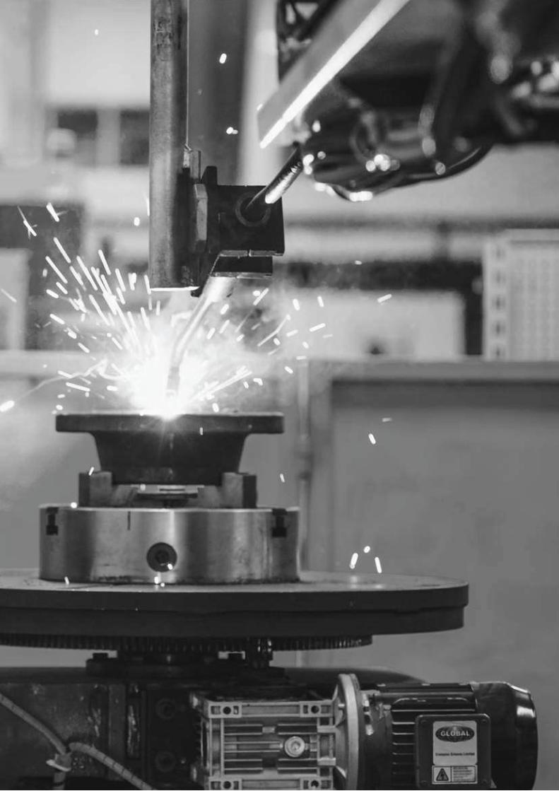
CLADDING PROCESS & CAPACITY:
Samamat Flow Control L.L.C. has the capacity to process from 4” to 36” Flanges and Valves.Maximum Bore Depth: up to 600mm Weldable Bore Dia.: 800mm Welding Speed: 340 to 450mm/min. Deposition Rate: 1.7 to 2.5kg/hr
The process is usually applied to increase the availability work sources for Gas Metal Arc Welding (GMAW) & Gas Tungsten Arc Welding (GTAW) cladding of the walls with metal alloys that are more resistant to wear.
HOW CLADDING WILL IMPROVE QUALITY OF COMPONENTS:
• Unusual alloy castings can include sub-surface defects, Cladding the surface produces a veryhigh-Quality layer with minimal imperfections.
• Cladding process that builds up the corrosion resistant alloy (CRA) layer of 1.5 to 3 mm on thewelded parts of �ange and Valve. It protects the piping system's integrity and provides a low costand long-term solution.
• A full range of NDT provides reassurance of quality.
CLADDING
1
2
3
4
5
6
7
8
9
10
11
12
13
14
15
16
17
18
19
20
21
22
23
24
25
26
27
28
Horizontal Turning Center
Horizontal Turning Mill Center
Vertical Machining Center
Vertical Turning Lathe
Surface Grinding Machine
Radial Drilling Machine
Pillar Drilling Machine
Heavy Duty Lathe
Medium Duty Lathe
Light Duty Lathe
Universal Milling Machine
Band Saw Cutting Machine
Horizontal Boring Machine
Vertical Slotting Machine
Thread Cutting Machine
Air Compressor
MIG Welding Machine
TIG Welding Machine
ARC Welding Machine
Vertical Hydro Testing Machine
Horizontal Hydro Testing Machine
Mobile Hydro Testing Machine
Wedge Lapping Machine
Body Lapping Machine 2” - 12”
Body Lapping Machine 14” - 24”
Marking Machine
A Frame Crane
A Frame Crane
CNC
CNC
CNC
CNC
Semi-Automatic
Manual
Manual
Manual
Manual
Manual
Manual
Semi-Automatic
Manual
Manual
Manual
Automatic
Semi-Automatic
Manual
Manual
Manual
Manual
Manual
Manual
Manual
Manual
Manual
6 Tons
3 Tons
1 No.
1 No.
1 No.
1 No.
1 No.
1 No.
1 No.
2 No’s.
2 No’s
3 No’s.
1 No.
2 No’s.
1 No.
2 No’s.
2 No’s.
1 No.
1 No.
1 No.
1 No.
1 No.
1 No.
1 No.
1 No.
1 No.
1 No.
1 No.
1 No.
3 No’s.
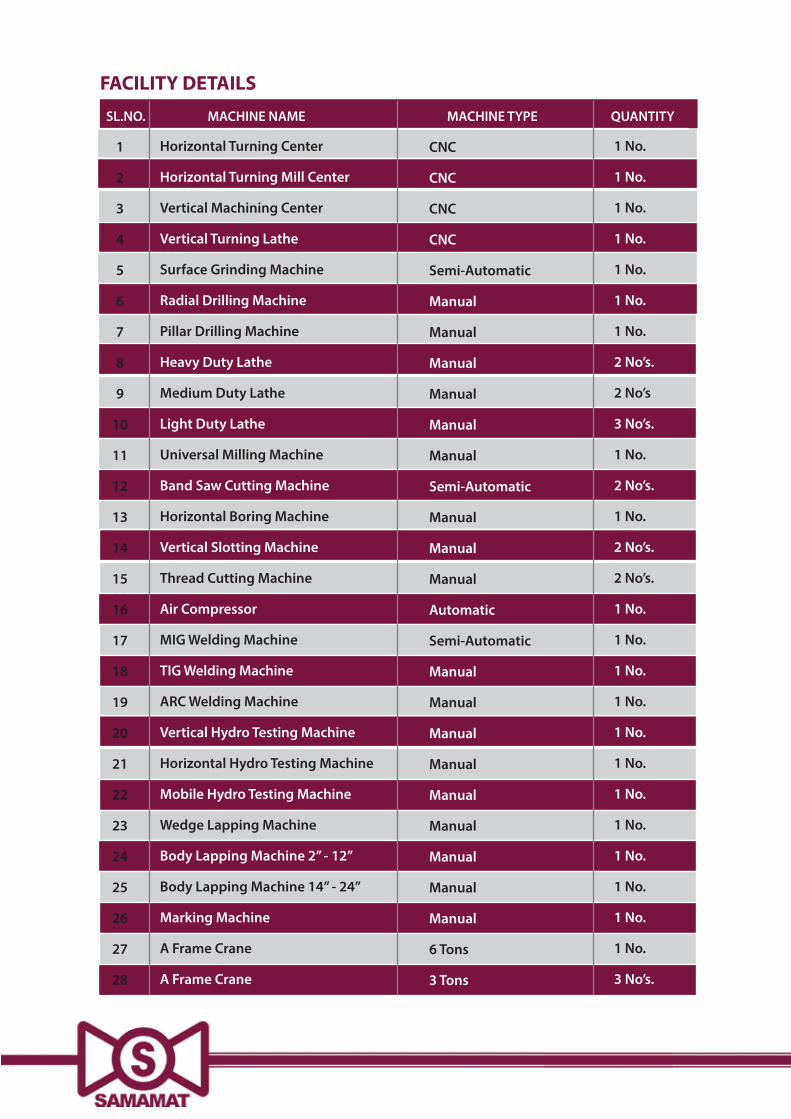
SL.NO. MACHINE NAME MACHINE TYPE QUANTITY
FACILITY DETAILS

Samamat Flow Control L.L.C.Warehouse No: 6, Plot No: 597-4904,Dubai Investments Park 2, Dubai, U.A.E.P.O. Box: 96047
+971 4 884 2212+971 4 884 2213