Embed Size (px)
Citation preview
GATEWAY PLAZA Wilmington, Delaware
500 Delaware Ave.
Elizabeth Hostutler - Structural Option 2 Dr. Hanagan - Spring 2006
TABLE OF CONTENTS
1.0 EXECUTIVE SUMMARY.............................................................................................3
2.0 BUILDING INFORMATION.......................................................................................4
2.1 Primary Engineering Systems ................................................................................7
2.2 Additional Engineering Systems ...........................................................................8
3.0 STRUCTURAL SYSTEM DESCRIPTION ............................................................9
4.0 PROBLEM STATEMENT AND SOLUTION PROPOSAL .........................13
5.0 DESIGN CRITERIA......................................................................................................15
5.1 Design Objectives..................................................................................................15
5.2 Design Procedure ..................................................................................................15
5.3 Loading Conditions..............................................................................................16
6.0 STRUCTURAL DEPTH .............................................................................................21
6.1 Post-tensioning ......................................................................................................21
6.1.1 Slab ................................................................................................................................ 21
6.1.2 Post-tensioned Beams ................................................................................................ 22
6.1.3 RAM Concept ............................................................................................................ 24
6.2 Regularly Reinforced............................................................................................28
6.2.1 Columns ....................................................................................................................... 28
6.2.2 Lateral System Design ............................................................................................... 30
6.3 Foundations ............................................................................................................33
7.0 STRUCTURAL SUMMARY.....................................................................................34
8.0 BREADTH STUDIES ...................................................................................................36
8.1 Mechanical Study ..................................................................................................36
8.2 Construction Study...............................................................................................40
9.0 CONCLUSIONS.............................................................................................................43
CREDITS AND ACKNOWLEDGEMENTS ....................................................................44
REFERENCES............................................................................................................................... 45
GATEWAY PLAZA Wilmington, Delaware
500 Delaware Ave.
Elizabeth Hostutler - Structural Option 3 Dr. Hanagan - Spring 2006
1.0 EXECUTIVE SUMMARY
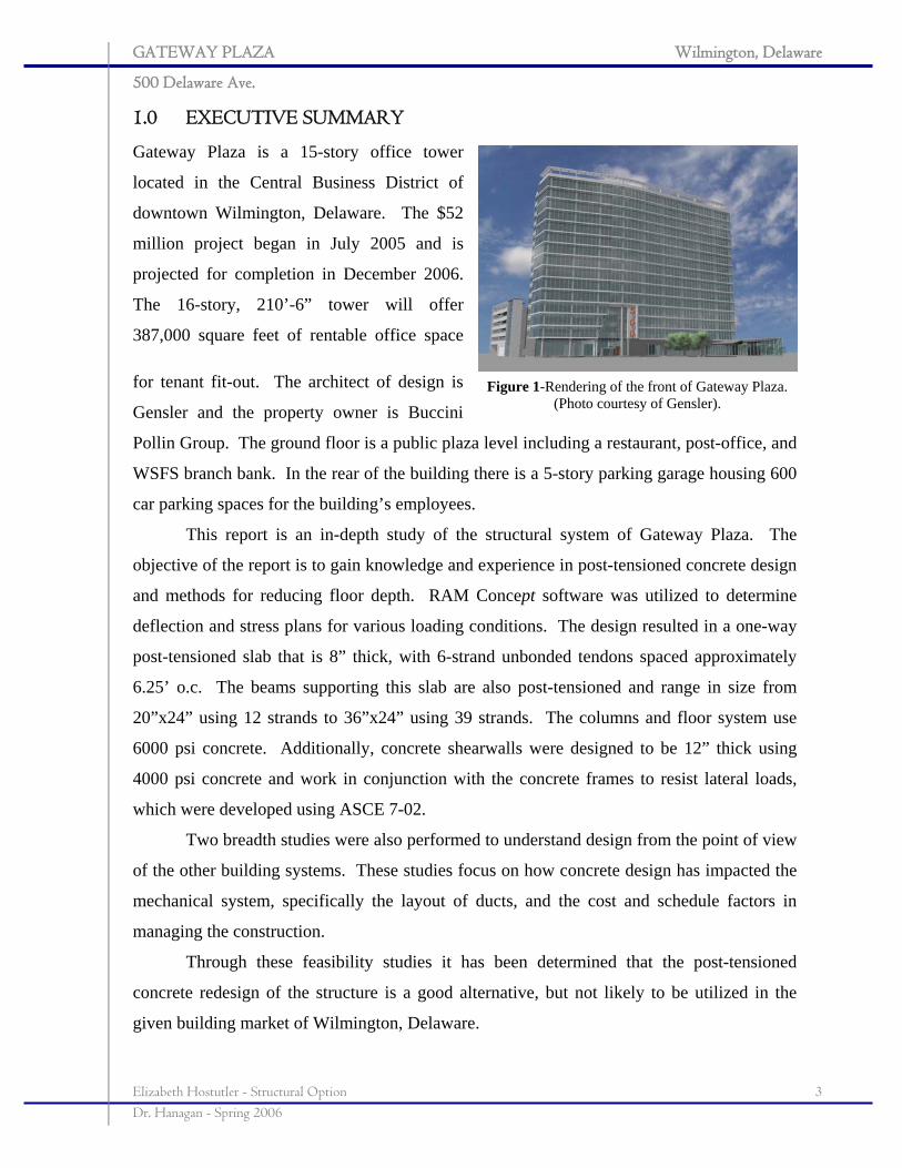
Gateway Plaza is a 15-story office tower
located in the Central Business District of
downtown Wilmington, Delaware. The $52
million project began in July 2005 and is
projected for completion in December 2006.
The 16-story, 210’-6” tower will offer
387,000 square feet of rentable office space
for tenant fit-out. The architect of design is
Gensler and the property owner is Buccini
Pollin Group. The ground floor is a public plaza level including a restaurant, post-office, and
WSFS branch bank. In the rear of the building there is a 5-story parking garage housing 600
car parking spaces for the building’s employees.
This report is an in-depth study of the structural system of Gateway Plaza. The
objective of the report is to gain knowledge and experience in post-tensioned concrete design
and methods for reducing floor depth. RAM Concept software was utilized to determine
deflection and stress plans for various loading conditions. The design resulted in a one-way
post-tensioned slab that is 8” thick, with 6-strand unbonded tendons spaced approximately
6.25’ o.c. The beams supporting this slab are also post-tensioned and range in size from
20”x24” using 12 strands to 36”x24” using 39 strands. The columns and floor system use
6000 psi concrete. Additionally, concrete shearwalls were designed to be 12” thick using
4000 psi concrete and work in conjunction with the concrete frames to resist lateral loads,
which were developed using ASCE 7-02.
Two breadth studies were also performed to understand design from the point of view
of the other building systems. These studies focus on how concrete design has impacted the
mechanical system, specifically the layout of ducts, and the cost and schedule factors in
managing the construction.
Through these feasibility studies it has been determined that the post-tensioned
concrete redesign of the structure is a good alternative, but not likely to be utilized in the
given building market of Wilmington, Delaware.
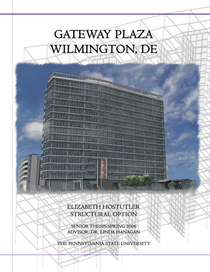
Figure 1-Rendering of the front of Gateway Plaza. (Photo courtesy of Gensler).
GATEWAY PLAZA Wilmington, Delaware
500 Delaware Ave.
Elizabeth Hostutler - Structural Option 4 Dr. Hanagan - Spring 2006
2.0 BUILDING INFORMATION
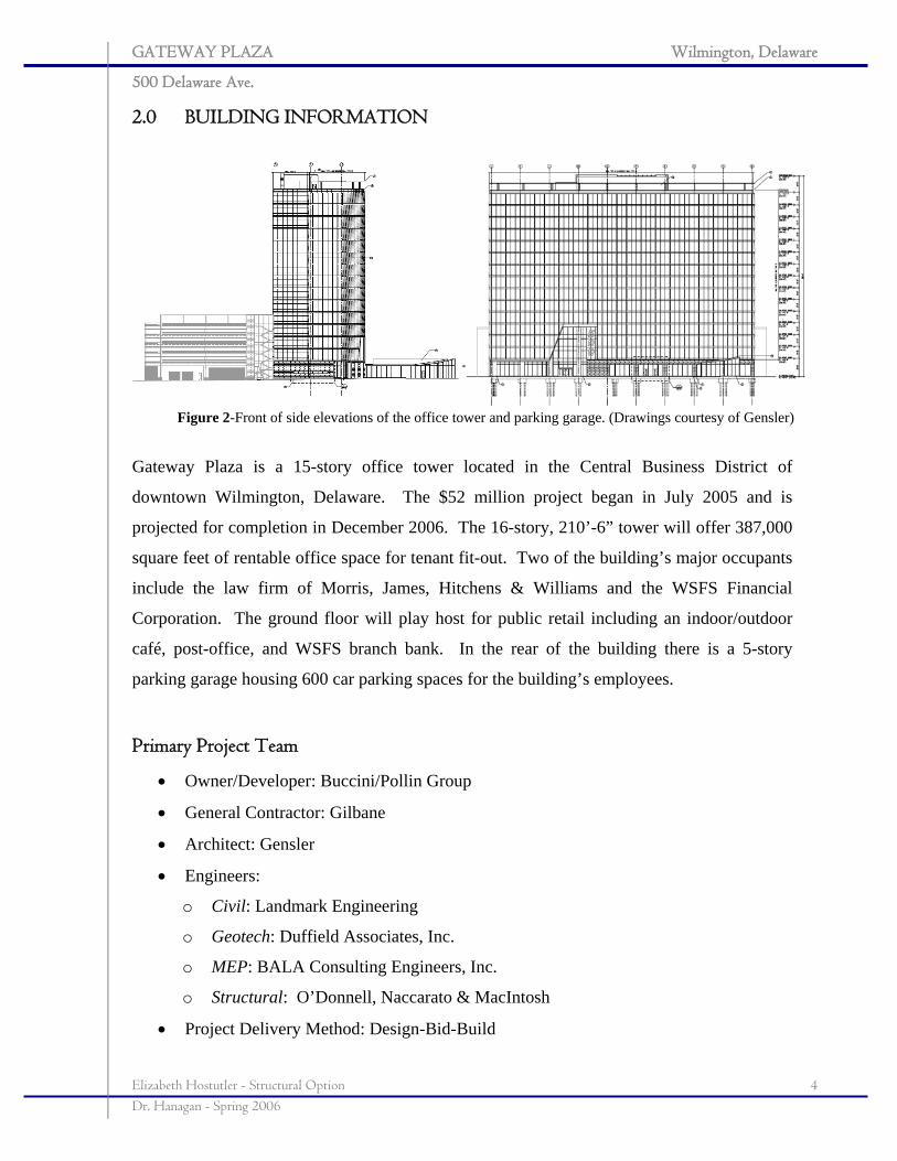
Gateway Plaza is a 15-story office tower located in the Central Business District of
downtown Wilmington, Delaware. The $52 million project began in July 2005 and is
projected for completion in December 2006. The 16-story, 210’-6” tower will offer 387,000
square feet of rentable office space for tenant fit-out. Two of the building’s major occupants
include the law firm of Morris, James, Hitchens & Williams and the WSFS Financial
Corporation. The ground floor will play host for public retail including an indoor/outdoor
café, post-office, and WSFS branch bank. In the rear of the building there is a 5-story
parking garage housing 600 car parking spaces for the building’s employees.
Primary Project Team
• Owner/Developer: Buccini/Pollin Group
• General Contractor: Gilbane
• Architect: Gensler
• Engineers:
o Civil: Landmark Engineering
o Geotech: Duffield Associates, Inc.
o MEP: BALA Consulting Engineers, Inc.
o Structural: O’Donnell, Naccarato & MacIntosh
• Project Delivery Method: Design-Bid-Build
Figure 2-Front of side elevations of the office tower and parking garage. (Drawings courtesy of Gensler)
GATEWAY PLAZA Wilmington, Delaware
500 Delaware Ave.
Elizabeth Hostutler - Structural Option 5 Dr. Hanagan - Spring 2006
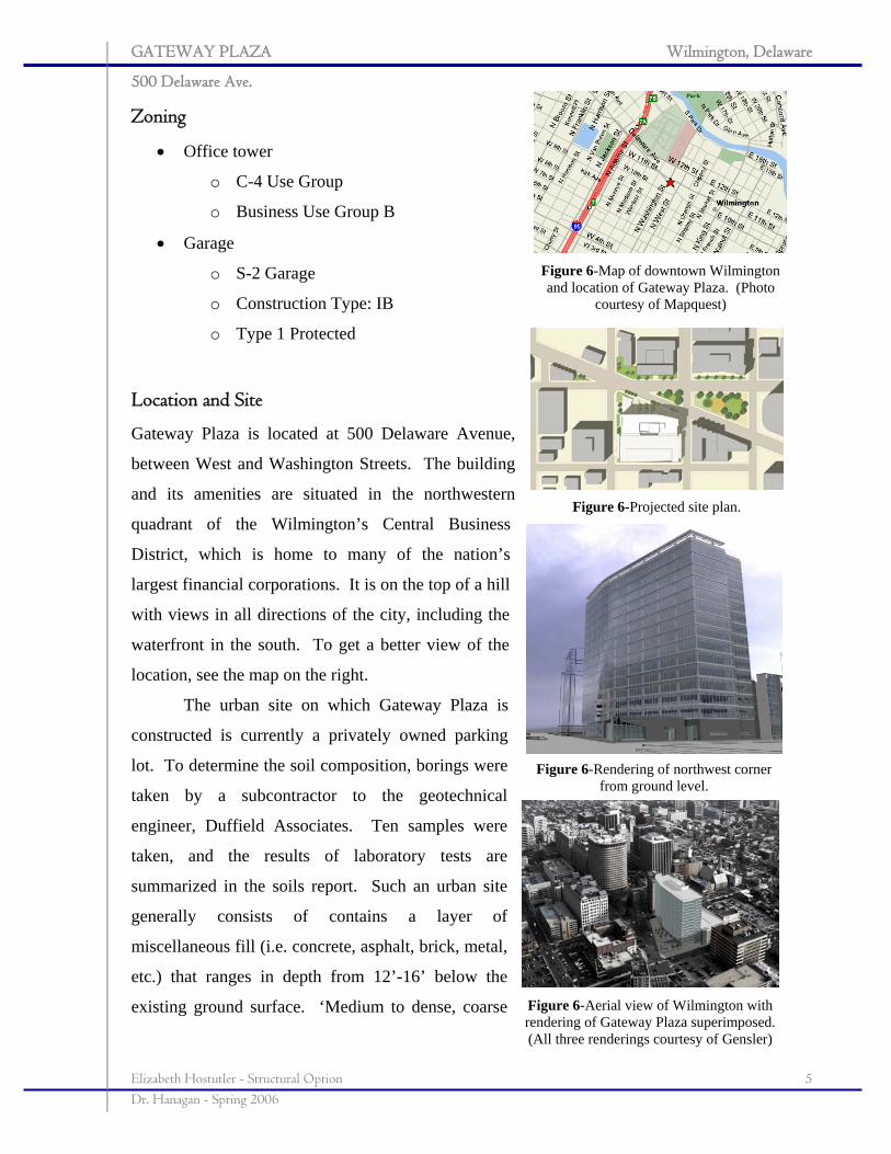
Figure 6-Map of downtown Wilmington and location of Gateway Plaza. (Photo
courtesy of Mapquest)
Figure 6-Projected site plan.
Figure 6-Rendering of northwest corner from ground level.
Figure 6-Aerial view of Wilmington with rendering of Gateway Plaza superimposed. (All three renderings courtesy of Gensler)
Zoning
• Office tower
o C-4 Use Group
o Business Use Group B
• Garage
o S-2 Garage
o Construction Type: IB
o Type 1 Protected
Location and Site
Gateway Plaza is located at 500 Delaware Avenue,
between West and Washington Streets. The building
and its amenities are situated in the northwestern
quadrant of the Wilmington’s Central Business
District, which is home to many of the nation’s
largest financial corporations. It is on the top of a hill
with views in all directions of the city, including the
waterfront in the south. To get a better view of the
location, see the map on the right.
The urban site on which Gateway Plaza is
constructed is currently a privately owned parking
lot. To determine the soil composition, borings were
taken by a subcontractor to the geotechnical
engineer, Duffield Associates. Ten samples were
taken, and the results of laboratory tests are
summarized in the soils report. Such an urban site
generally consists of contains a layer of
miscellaneous fill (i.e. concrete, asphalt, brick, metal,
etc.) that ranges in depth from 12’-16’ below the
existing ground surface. ‘Medium to dense, coarse
GATEWAY PLAZA Wilmington, Delaware
500 Delaware Ave.
Elizabeth Hostutler - Structural Option 6 Dr. Hanagan - Spring 2006
grained soils and medium to stiff consistency silt and clay soils lay beneath the miscellaneous
fill layer. Their depths range from approximately 57’-63’ below the existing ground
surface.” Finally, dense to very dense sand soils, evidence of weathered bedrock, lay below
the sandy silt layer.
Architecture
Gateway Plaza is the first new building to be constructed in Wilmington's Central Business
District (CBD) in 15 years. The tower will fill in the gap between neighboring office towers.
It is predicted to be a landmark among all of the CBD's office towers because it will have one
of the few all-glass curtain walls in town. The curtain wall will give the façade a more
modern feel than the dated 1970s architecture of the DuPont Hotel and the “cookie-cutter”
appearance of the Sheraton Hotel, which both have concrete facades. The northeast quadrant
of the tower features a corner that appears to be “sliced” off at an angle that imitates the
angle of Delaware Ave.
The main entrance to the lobby has a 5-story cut-out of the front façade. The public
café on the ground level adds interest to the building because it protrudes out of the footprint
of the main tower and features a kinked, standing seam, metal roof. The protrusion creates a
courtyard in front of the entrance and allows for shaded outdoor seating, a new feature to the
CBD. The remaining 14 stories of the tower remain office space for tenant fit-outs.
Building Envelope
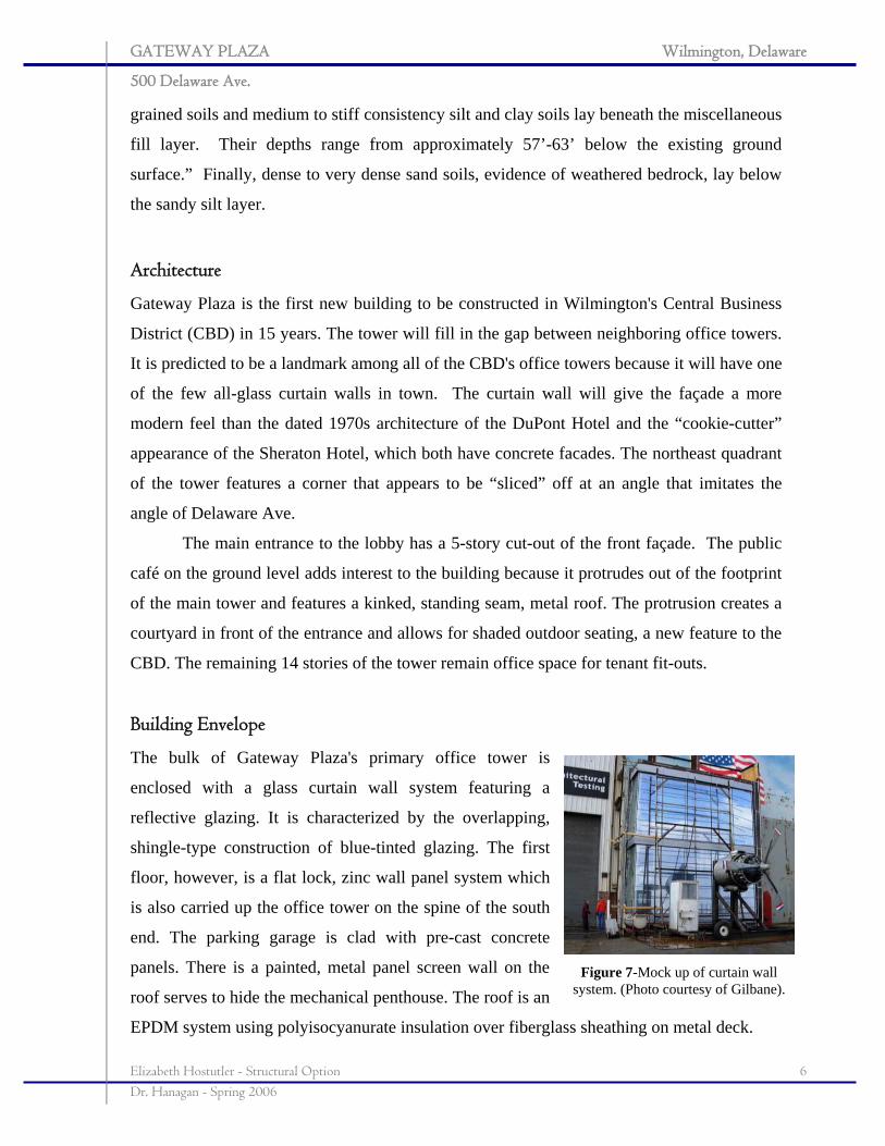
The bulk of Gateway Plaza's primary office tower is
enclosed with a glass curtain wall system featuring a
reflective glazing. It is characterized by the overlapping,
shingle-type construction of blue-tinted glazing. The first
floor, however, is a flat lock, zinc wall panel system which
is also carried up the office tower on the spine of the south
end. The parking garage is clad with pre-cast concrete
panels. There is a painted, metal panel screen wall on the
roof serves to hide the mechanical penthouse. The roof is an
EPDM system using polyisocyanurate insulation over fiberglass sheathing on metal deck.
Figure 7-Mock up of curtain wall system. (Photo courtesy of Gilbane).
GATEWAY PLAZA Wilmington, Delaware
500 Delaware Ave.
Elizabeth Hostutler - Structural Option 7 Dr. Hanagan - Spring 2006
2.1 Primary Engineering Systems
Mechanical
The variable volume mechanical system of Gateway Plaza is located on the roof in a
mechanical penthouse. Here, the 3-cell water cooling tower and heat pumps supply
conditioned air to all 15 floors of the building. On floors 2-15, there are direct exchange air
conditioning units using R-22 refrigerant. In the building's IT/Telephone room on the first
floor, there is a Liebert Challenger 3000 air conditioning unit to provide up to 5 tons of
cooling control the temperature and humidity required by the sensitive computing equipment.
Since the building is to be fit out, space for the risers has been designated to a
mechanical room found on each floor in the tower's service core. Return air from each floor
is dumped into the mechanical room and is exhausted. There are outdoor air louvers in each
room to replace the exhausted air and provide ventilation.
Electrical
Gateway Plaza's electrical system is powered by both 480/277V and 208/120V panel boards.
Power is supplied to the building by two 2500/3325 kVA transformers. There are two main
distribution panels that service floors 1-8 and floors 9-roof, respectively. The voltage is
stepped down through transformers on the second, fifth, eighth, eleventh, and fourteenth
floors in electrical rooms in the building’s core. A 1600A bus riser supplies power to the
typical office levels for lighting and receptacles. There is a 750kW, 938 kVA emergency
generator which services the fire pumps.
Lighting
Lighting for the service core of the typical office floors is provided with 6" open reflector
down lights with compact fluorescent lamps. For the tenant spaces, the lighting plans will be
finalized upon fit-out. On the exterior plaza area, metal halide downlights flood the walls of
the first floor with light. Illuminating strips with tempered glass lenses are located under trees
to light the plaza and seating areas.
GATEWAY PLAZA Wilmington, Delaware
500 Delaware Ave.
Elizabeth Hostutler - Structural Option 8 Dr. Hanagan - Spring 2006
2.2 Additional Engineering Systems
Fire Protection
Almost every area of Gateway Plaza is protected by a wet sprinkler system with a 4" wet
standpipe in each of the two stairwells. The water is supplied to the standpipes by a fire pump
and a jockey pump for the higher floors; both are located on the 1st floor in the water service
room. The fire pump has a capacity of 750 GPM and the jockey pump has a capacity of 109
GPM. These can run on emergency power supplied by a diesel generator.
Transportation
Gateway Plaza has a central service core servicing most of the building's transportation
needs. There are 5 public elevators, 1 service elevator, and two stairwells in the core. The
public elevators and stairwells run to all floors of the office tower and the service elevator
will also run to the mechanical penthouse.
The main entrance to the public is on Delaware Ave. and will have a vestibule to
control air loss. The service core can be accessed from this main entrance, while the public
areas will have separate entrances also along Delaware Ave. including one to the café and
one to the WSFS bank.
Telecommunications
The building has a main technology/data center on the ground floor. It is located in the
parking garage and will service all of the security systems and telephone lines in the building.
GATEWAY PLAZA Wilmington, Delaware
500 Delaware Ave.
Elizabeth Hostutler - Structural Option 9 Dr. Hanagan - Spring 2006
3.0 STRUCTURAL SYSTEM DESCRIPTION
Gateway Plaza has two distinct buildings and two distinct building systems. The office
tower is composite steel construction with braced frames and the parking garage is pre-cast
concrete with pre-cast shearwalls. The two structures are separated using a 2” expansion
joint. The structural engineer is responsible for designing the office tower and the pre-cast
supplier is responsible for the design of the garage. For this reason, focus will be centered on
the office tower design.
Foundations
Due to the poor soil conditions on site, deep foundations were deemed necessary for the high
gravity column loads and overturning moments from lateral resisting elements. The soils
report recommended end-bearing caissons, but due to designer preference, concrete filled,
steel tube piles were chosen. The piles are 12” in diameter and use high strength concrete to
develop 120 tons of end-bearing capacity per pile. Most of the piles are drilled 70’ down to
bedrock. The clusters are topped with pile caps that range from 40”-65” thick. Grade beams
span the pile caps around the entire building’s perimeter, and a 5” slab on grade span the
grade beams in much of the foundation and are intermittently supported by single piles.
The office tower’s steel columns sit on pile caps of various shapes. The columns
from the lateral load resisting system generally sit on clusters of 18 piles or more where those
from the gravity system sit on clusters of 6-12. The larger foundations under the lateral
frames are to resist the overturning moment from wind and seismic loading. The pile clusters
in the office tower are on a 30‘x52’ grid on the north side and a 30’x36’ grid on the south
side (see the foundation plan on next page).
The vertical support members in the parking garage sit on pile caps that are 40-50”
thick and are generally square. The lateral load resisting system of the garage, pre-cast
concrete shearwalls, sits on 7-pile clusters while the cast-in-place concrete columns rest on 4-
pile clusters. The clusters in the parking garage are on a 30’x62’ grid (not shown).
GATEWAY PLAZA Wilmington, Delaware
500 Delaware Ave.
Elizabeth Hostutler - Structural Option 10 Dr. Hanagan - Spring 2006
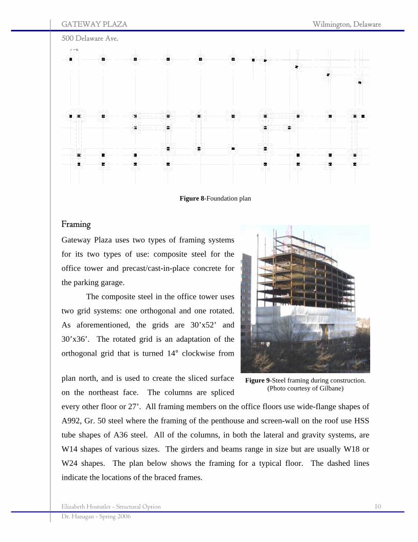
Figure 8-Foundation plan
Framing
Gateway Plaza uses two types of framing systems
for its two types of use: composite steel for the
office tower and precast/cast-in-place concrete for
the parking garage.
The composite steel in the office tower uses
two grid systems: one orthogonal and one rotated.
As aforementioned, the grids are 30’x52’ and
30’x36’. The rotated grid is an adaptation of the
orthogonal grid that is turned 14° clockwise from
plan north, and is used to create the sliced surface
on the northeast face. The columns are spliced
every other floor or 27’. All framing members on the office floors use wide-flange shapes of
A992, Gr. 50 steel where the framing of the penthouse and screen-wall on the roof use HSS
tube shapes of A36 steel. All of the columns, in both the lateral and gravity systems, are
W14 shapes of various sizes. The girders and beams range in size but are usually W18 or
W24 shapes. The plan below shows the framing for a typical floor. The dashed lines
indicate the locations of the braced frames.
Figure 9-Steel framing during construction. (Photo courtesy of Gilbane)
GATEWAY PLAZA Wilmington, Delaware
500 Delaware Ave.
Elizabeth Hostutler - Structural Option 11 Dr. Hanagan - Spring 2006
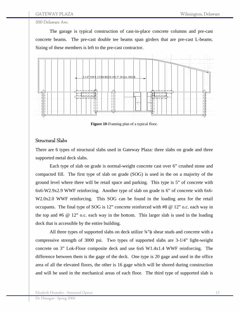
The garage is typical construction of cast-in-place concrete columns and pre-cast
concrete beams. The pre-cast double tee beams span girders that are pre-cast L-beams.
Sizing of these members is left to the pre-cast contractor.
Structural Slabs
There are 6 types of structural slabs used in Gateway Plaza: three slabs on grade and three
supported metal deck slabs.
Each type of slab on grade is normal-weight concrete cast over 6” crushed stone and
compacted fill. The first type of slab on grade (SOG) is used in the on a majority of the
ground level where there will be retail space and parking. This type is 5” of concrete with
6x6-W2.9x2.9 WWF reinforcing. Another type of slab on grade is 6” of concrete with 6x6-
W2.0x2.0 WWF reinforcing. This SOG can be found in the loading area for the retail
occupants. The final type of SOG is 12” concrete reinforced with #8 @ 12” o.c. each way in
the top and #6 @ 12” o.c. each way in the bottom. This larger slab is used in the loading
dock that is accessible by the entire building.
All three types of supported slabs on deck utilize ¾”φ shear studs and concrete with a
compressive strength of 3000 psi. Two types of supported slabs are 3-1/4” light-weight
concrete on 3” Lok-Floor composite deck and use 6x6 W1.4x1.4 WWF reinforcing. The
difference between them is the gage of the deck. One type is 20 gage and used in the office
area of all the elevated floors, the other is 16 gage which will be shored during construction
and will be used in the mechanical areas of each floor. The third type of supported slab is
Figure 10-Framing plan of a typical floor.
GATEWAY PLAZA Wilmington, Delaware
500 Delaware Ave.
Elizabeth Hostutler - Structural Option 12 Dr. Hanagan - Spring 2006
found on the penthouse floor and is 2-1/2” of normal-weight concrete on 1-1/2” Lok-Floor
composite deck. It, too, uses 6x6 W1.4xW1.4 WWF reinforcing.
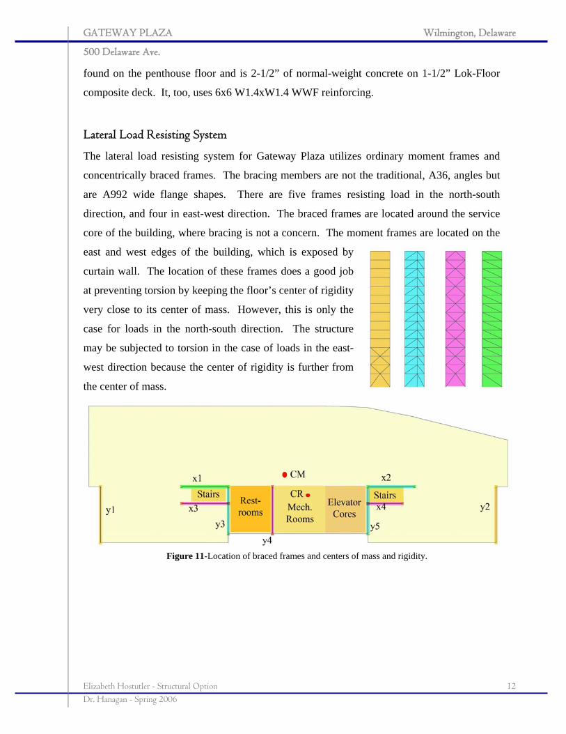
Lateral Load Resisting System
The lateral load resisting system for Gateway Plaza utilizes ordinary moment frames and
concentrically braced frames. The bracing members are not the traditional, A36, angles but
are A992 wide flange shapes. There are five frames resisting load in the north-south
direction, and four in east-west direction. The braced frames are located around the service
core of the building, where bracing is not a concern. The moment frames are located on the
east and west edges of the building, which is exposed by
curtain wall. The location of these frames does a good job
at preventing torsion by keeping the floor’s center of rigidity
very close to its center of mass. However, this is only the
case for loads in the north-south direction. The structure
may be subjected to torsion in the case of loads in the east-
west direction because the center of rigidity is further from
the center of mass.
Figure 11-Location of braced frames and centers of mass and rigidity.
GATEWAY PLAZA Wilmington, Delaware
500 Delaware Ave.
Elizabeth Hostutler - Structural Option 13 Dr. Hanagan - Spring 2006
4.0 PROBLEM STATEMENT AND SOLUTION PROPOSAL
An area for redesign was difficult to pinpoint with Gateway Plaza. After the research and
analysis performed during Technical Assignments 1-3, it has been determined that the
current structural systems--steel framing, concentrically braced frames, and deep
foundations--was the best given building type, local conditions and accepted practice.
Though no feasible framing alternatives were found during research for Technical Report 2:
Pro-con Study of Alternate Framing Systems, further research and faculty consultation has
suggested that a one-way post-tensioned concrete slab system is worth considering. There
are no height restrictions dictated by the architect or zoning ordinances, but the post-
tensioned system could add a significant amount of ceiling space. The purpose behind this
design is to gain knowledge and experience in the design of post-tensioned concrete systems
in buildings.
Proposed Problem Solution
As mentioned in the problem statement above, post-tensioned concrete slabs and beams will
be designed to replicate the architectural requirements of the building by adhering to the
given column grids. To achieve this, cast-in-place columns, post-tensioned beams and slabs,
and shearwalls will be designed. Although foundations will not be explicitly designed, they
will be sized approximately for end bearing strength. Making an appropriate comparison of
the concrete system to the steel system will require the consideration of the following factors:
cost, project duration, and impact on foundations.
Method for Solution
In order to redesign the building using post-tensioned concrete slabs, research must initially
be performed to gain knowledge in how to design such a system. By researching texts,
journals, and code manuals, a good deal of technical knowledge should be gained. By
talking with students whose thesis buildings use post-tensioned concrete in their existing
designs and professionals in the industry, significant knowledge of practical design shall be
gained.
GATEWAY PLAZA Wilmington, Delaware
500 Delaware Ave.
Elizabeth Hostutler - Structural Option 14 Dr. Hanagan - Spring 2006
Once a significant amount of information has been gathered, schematic designs will
commence. A preliminary framing plan will be laid out and the office floors will be
designed using loads obtained in Technical Report 1: Existing Building Conditions. The first
round of analysis for all members will be performed by hand calculations using ACI 318-05
Building Code Requirements for Reinforced Concrete and The Post-tensioning Manual.
Further analysis will be completed using structural software including: ENERCALC, RAM
Structural System, and Concept. Finally, wind and seismic loads will be computed by hand
and applied to the structure. A design for the lateral system will be designed and checked in
RAM Frame for all possible loading cases and combinations as laid out in Chapter 2 of
ASCE 7-02.
Once the design has been finalized, a proper comparison shall be made between the
composite steel framing and the post-tensioned concrete framing based on the factors
mentioned above.
GATEWAY PLAZA Wilmington, Delaware
500 Delaware Ave.
Elizabeth Hostutler - Structural Option 15 Dr. Hanagan - Spring 2006
5.0 DESIGN CRITERIA
5.1 Design Objectives
The main objective of this project is to find an alternative structural system that will perform
as well as steel in achieving long-span bays. Additionally, the chosen type of system should
allow greater control in determining floor depths. Therefore, keeping these depths to a
minimum will be of great importance. In order to meet this goal, the following standards
must be met:
• Long bay spans must be preserved.
• Service spaces in the building’s core must remain unchanged.
• Limit the overall floor depth to 24”.
• Keep shearwalls in locations similar to those of the braced frames.
• Design must be in compliance with model codes set forth by ACI 318-05, IBC 2003,
and ASCE 7-05.
5.2 Design Procedure
To make this project manageable, one of the main assumptions considered is that floors 2-5
are one type of typical floor and floors 6-15 are a second type of typical floor. Since the
office tower is the responsibility of the structural designer, it alone will be considered for the
redesign. The garage will be omitted from design because it is the responsibility of the
precast manufacturer.
All schematic designs will be performed by traditional hand calculations using
procedures outlined in concrete design texts by Antoine Naaman and Charles Nilson as well
as ACI 318-05. Spreadsheets containing the calculations embedded in these procedures will
be created to ease repetition. The preliminary designs yielded by the spreadsheets (available
in Appendix B: Preliminary Member Design) will be entered into ENERCALC to confirm
hand calculations. A structure of these preliminary members will be modeled in RAM
structural design software for refinement. The gravity system will be checked and refined
using RAM Concrete and post-tensioned elements including slabs and beams will use RAM
Concept. Concept will be used to check concrete stresses and deflections under service
conditions as well as design minimum reinforcing. The lateral system will be analyzed
GATEWAY PLAZA Wilmington, Delaware
500 Delaware Ave.
Elizabeth Hostutler - Structural Option 16 Dr. Hanagan - Spring 2006
further using RAM Frame to scrutinize lateral loads and compare them to hand calculations,
as well as obtain building drifts under various load cases and combinations.
5.3 Loading Conditions
5.3.1 Gravity Loads
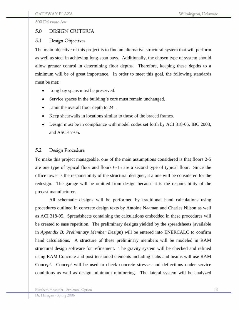
5.3.1.1 Dead and Live
Dead loads include the self-weight of the
structure and any additional loads
accounting for sprinklers, MEP, and
collateral loading. It is evident that the
total dead load is greater for the concrete
design than it was for the composite steel
design, 115 psf compared to 65 psf. The
live loading conditions comply with
those set forth in IBC 2003.
A majority of the office tower is
classified as office occupancy which
results in a live load of 60 psf, plus an
additional 20 psf for partitions. Although
the loads are not consistent with those of
the original designer, they are still
conservative and comply with IBC 2003. There are portions on each floor considered to be
service spaces which house HVAC and electrical equipment in mechanical rooms. These
spaces, subjected to heavy equipment loads, will be designed for a 125 psf live load. This
area is illustrated on the typical floor in the diagram above. The table above summarizes the
gravity loading conditions in each type of occupancy.
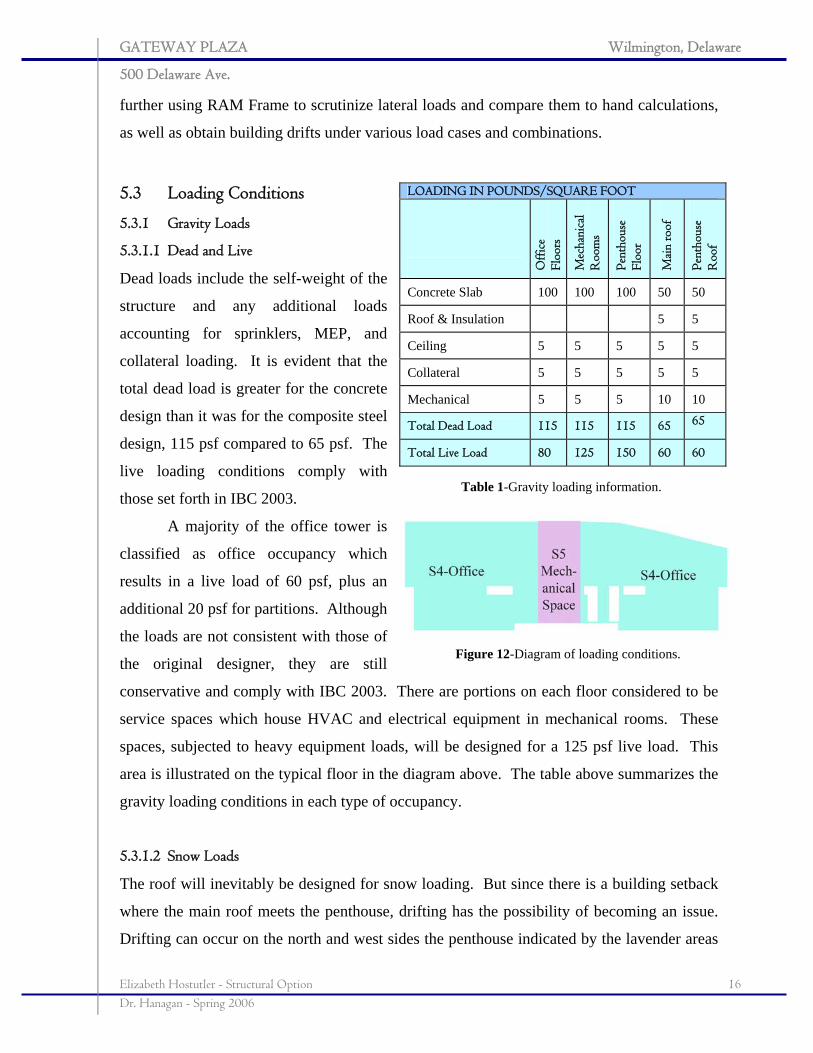
5.3.1.2 Snow Loads
The roof will inevitably be designed for snow loading. But since there is a building setback
where the main roof meets the penthouse, drifting has the possibility of becoming an issue.
Drifting can occur on the north and west sides the penthouse indicated by the lavender areas
LOADING IN POUNDS/SQUARE FOOT
Off
ice
Floo
rs
Mec
hani
cal
Roo
ms
Pent
hous
e Fl
oor
Mai
n ro
of
Pent
hous
e R
oof
Concrete Slab 100 100 100 50 50
Roof & Insulation 5 5
Ceiling 5 5 5 5 5
Collateral 5 5 5 5 5
Mechanical 5 5 5 10 10
Total Dead Load 115 115 115 65 65
Total Live Load 80 125 150 60 60
Table 1-Gravity loading information.
Figure 12-Diagram of loading conditions.
GATEWAY PLAZA Wilmington, Delaware
500 Delaware Ave.
Elizabeth Hostutler - Structural Option 17 Dr. Hanagan - Spring 2006
labeled 1 and 2 in the diagram to the
right. A spreadsheet was developed
according to the ASCE 7-02 guidelines
set out in Chapter 7. In section 1, the
maximum drift load was found to be 49
psf and in section 2, the load was found to be 63 psf. For further details on the calculations,
please refer to Appendix A.1: Snow Loading.
5.3.2 Lateral Loads
The lateral loads, both wind and seismic, for the building were found using the guidelines set
forth in IBC 2003 and ASCE7-02. Complete calculations were found using spreadsheets;
please refer to Appendix A.2: Lateral Loading for intermediate steps. Although the wind
loads for Gateway Plaza did not change due the redesign, seismic loads increased
dramatically due to the increase in the structure’s weight.
The wind load is distinctly greater in the north-south direction because the building
dimension perpendicular to this direction is 270’, which is three times larger than that in the
opposite direction, and collects a great deal more pressure. In the east-west direction,
however, seismic loads were found to control due to the increase in building weight.
Considering both load types--seismic and all four cases of wind--and including accidental
eccentricity, the only cases that resulted in unfavorable results were those that included
eccentricity. In addition to the existing eccentricity between the center of rigidity and the
center of mass, the accidental eccentricity created unfavorable rotations. Load combinations
checked by RAM Frame include those from ASCE 7-02 in Chapter 2.0 for strength design:
1. ( )D4.1
2. ( ) ( ) ( )orSLLD r5.06.12.1 ++
3. ( ) ( ) ( )WLorSorLD r 8.05.06.12.1 ++
4. ( ) ( ) ( )orSLLWD r5.06.12.1 +++ Controls in N-S
5. SLED 2.05.00.12.1 +++
6. ( ) ( )WD 6.19.0 +
7. ( ) ( )ED 0.19.0 + Controls in E-W
Figure 13-Areas of concern for snow drift.
GATEWAY PLAZA Wilmington, Delaware
500 Delaware Ave.
Elizabeth Hostutler - Structural Option 18 Dr. Hanagan - Spring 2006
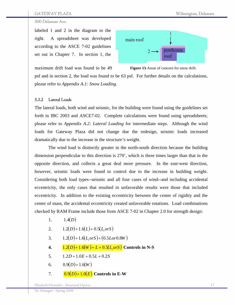
5.3.2.1 Wind Loading
Wind Loads on the Main Wind Force Resisting System were found according to the
Analytical Procedure, outlined in Section 6.5. To find the story forces and shears, a tributary
area approach was taken. The pressure at each floor level was distributed over an area equal
to half the floor height above and below the level. As would be expected from a building on
the coastal Northeastern United States, wind is the
controlling load case in the north-south direction.
The basic wind loading characteristics are:
• Basic Wind Speed: 90 mph
• Wind Load Importance: 1.0
• Exposure Category: B
• Internal Pressure Coefficient: +/- 0.18
• Height: 210.5”
• Maximum wind pressure at roof: 23.3 psf
These characteristics were used to find the
following loads on the building in both
characteristic directions. The loads and controlling drift tabulated on page 20 are summaries
of RAM output, which are similar to the hand calculations performed according to ASCE 7-
02. ASCE 7’s Case 4 resulted in a building drift of 2.96”, approximately h/850, which is
considered very acceptable.
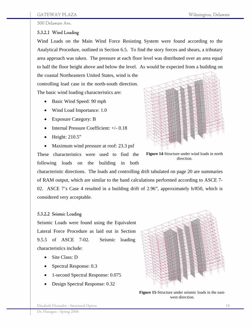
5.3.2.2 Seismic Loading
Seismic Loads were found using the Equivalent
Lateral Force Procedure as laid out in Section
9.5.5 of ASCE 7-02. Seismic loading
characteristics include:
• Site Class: D
• Spectral Response: 0.3
• 1-second Spectral Response: 0.075
• Design Spectral Response: 0.32
Figure 14-Structure under wind loads in north direction.
Figure 15-Structure under seismic loads in the east-west direction.
GATEWAY PLAZA Wilmington, Delaware
500 Delaware Ave.
Elizabeth Hostutler - Structural Option 19 Dr. Hanagan - Spring 2006
• 1-second Design Spectral Response: 0.12
• Seismic Use Group: II
• Seismic Design Category: B
• Seismic Importance Factor: 1.0
• Response Modification Factor: 3
• Base shear: 709 k
These characteristics were used to find the following loads on the building in both
characteristic directions. The loads and controlling drift are tabulated on the next page. Case
7 was shown to control drift in the east-west direction, 2.25”. Again, this is an acceptable
drift limit.
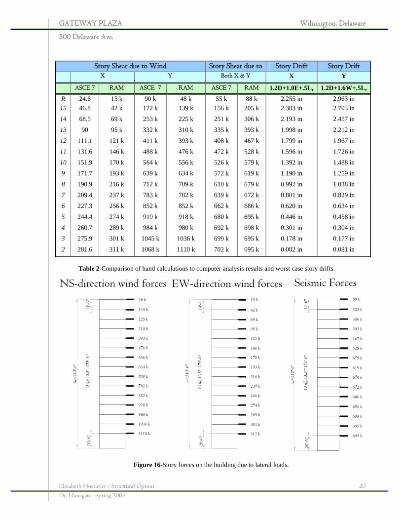
The table on the next page summarizes the story shears in both, north-south and east-
west, directions according to RAM Frame and hand calculations performed according to
ASCE 7-02. Additionally, it tabulates the maximum story drifts according to the controlling
load combinations. The diagrams below depict how these forces act on the building in both
directions.
GATEWAY PLAZA Wilmington, Delaware
500 Delaware Ave.
Elizabeth Hostutler - Structural Option 20 Dr. Hanagan - Spring 2006
Story Shear due to Wind Story Shear due to Story Drift Story Drift X Y Both X & Y X Y
ASCE 7 RAM ASCE 7 RAM ASCE 7 RAM 1.2D+1.0E+.5Lr 1.2D+1.6W+.5Lr
R 24.6 15 k 90 k 48 k 55 k 88 k 2.255 in 2.963 in 15 46.8 42 k 172 k 139 k 156 k 205 k 2.383 in 2.703 in
14 68.5 69 k 253 k 225 k 251 k 306 k 2.193 in 2.457 in
13 90 95 k 332 k 310 k 335 k 393 k 1.998 in 2.212 in
12 111.1 121 k 411 k 393 k 408 k 467 k 1.799 in 1.967 in
11 131.6 146 k 488 k 476 k 472 k 528 k 1.596 in 1.726 in
10 151.9 170 k 564 k 556 k 526 k 579 k 1.392 in 1.488 in
9 171.7 193 k 639 k 634 k 572 k 619 k 1.190 in 1.259 in
8 190.9 216 k 712 k 709 k 610 k 679 k 0.992 in 1.038 in
7 209.4 237 k 783 k 782 k 639 k 672 k 0.801 in 0.829 in
6 227.3 256 k 852 k 852 k 662 k 686 k 0.620 in 0.634 in
5 244.4 274 k 919 k 918 k 680 k 695 k 0.446 in 0.458 in
4 260.7 289 k 984 k 980 k 692 k 698 k 0.301 in 0.304 in
3 275.9 301 k 1045 k 1036 k 699 k 695 k 0.178 in 0.177 in
2 281.6 311 k 1068 k 1110 k 702 k 695 k 0.082 in 0.081 in
Table 2-Comparison of hand calculations to computer analysis results and worst case story drifts.
Figure 16-Story forces on the building due to lateral loads.
GATEWAY PLAZA Wilmington, Delaware
500 Delaware Ave.
Elizabeth Hostutler - Structural Option 21 Dr. Hanagan - Spring 2006
6.0 STRUCTURAL DEPTH
6.1 Post-tensioning
6.1.1 Slab
Spanning 52.5’ with regular reinforced concrete is very difficult, and nearly impossible to
stay within reasonable floor depths. For this reason, it has been concluded that a one-way
post-tensioned floor system is the best candidate for redesign. The 52.5’ span also requires
the concrete to have a high compressive strength to withstand the large stress imposed by the
prestressing tendons. For this reason, the monolithically cast slab and beam floor system will
be designed using 6000 psi concrete. The slab spans the 30’-0” direction and is framed out
by post-tensioned beams along column grid lines. Initial designs and hand calculations were
performed following an example published by the Portland Cement Association. The
example conforms to the concrete and steel stress limits provided by Chapter 18 in ACI 318-
02 and is classified as Class U, uncracked. For detailed calculations, see Appendix B.1: Post-
tensioned Slab.
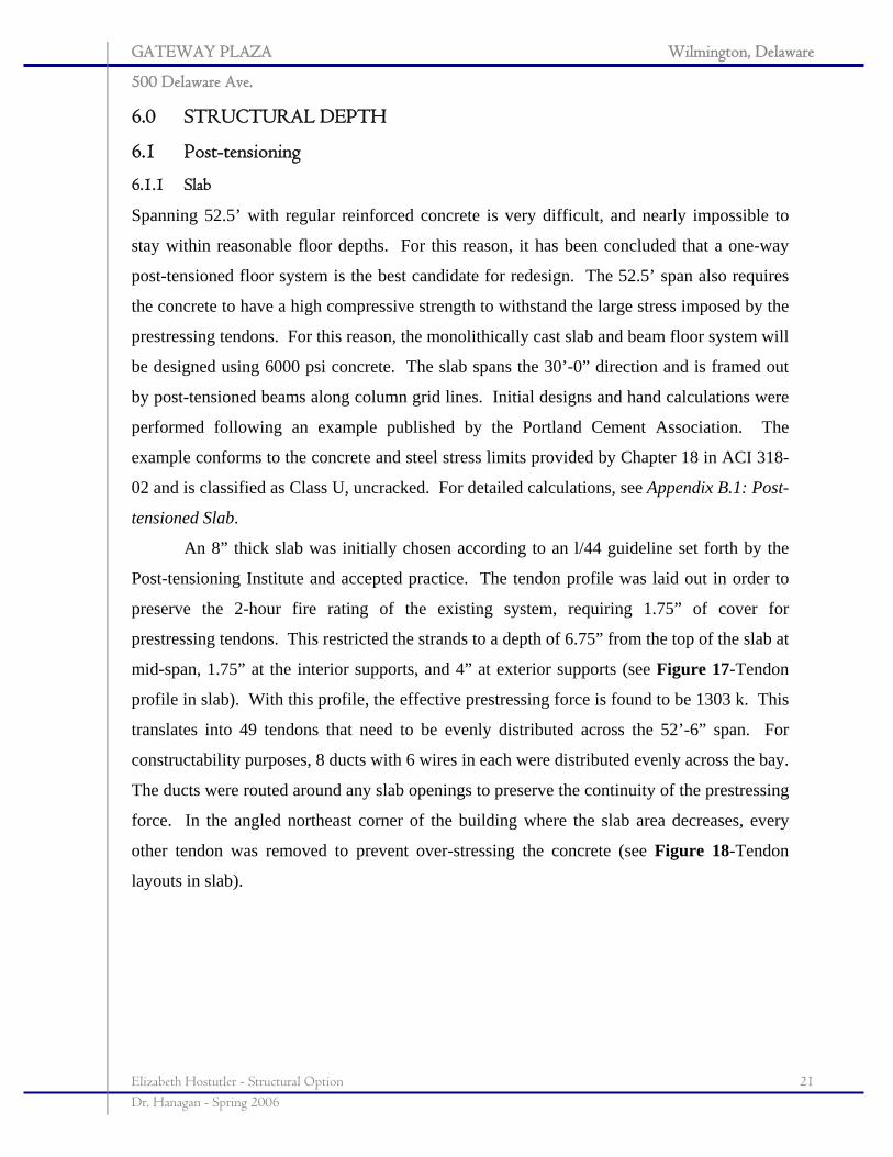
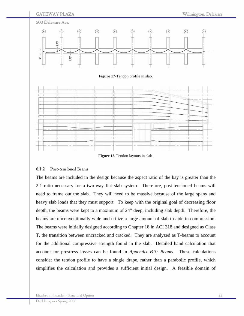
An 8” thick slab was initially chosen according to an l/44 guideline set forth by the
Post-tensioning Institute and accepted practice. The tendon profile was laid out in order to
preserve the 2-hour fire rating of the existing system, requiring 1.75” of cover for
prestressing tendons. This restricted the strands to a depth of 6.75” from the top of the slab at
mid-span, 1.75” at the interior supports, and 4” at exterior supports (see Figure 17-Tendon
profile in slab). With this profile, the effective prestressing force is found to be 1303 k. This
translates into 49 tendons that need to be evenly distributed across the 52’-6” span. For
constructability purposes, 8 ducts with 6 wires in each were distributed evenly across the bay.
The ducts were routed around any slab openings to preserve the continuity of the prestressing
force. In the angled northeast corner of the building where the slab area decreases, every
other tendon was removed to prevent over-stressing the concrete (see Figure 18-Tendon
layouts in slab).
GATEWAY PLAZA Wilmington, Delaware
500 Delaware Ave.
Elizabeth Hostutler - Structural Option 22 Dr. Hanagan - Spring 2006
Figure 17-Tendon profile in slab.
Figure 18-Tendon layouts in slab.
6.1.2 Post-tensioned Beams
The beams are included in the design because the aspect ratio of the bay is greater than the
2:1 ratio necessary for a two-way flat slab system. Therefore, post-tensioned beams will
need to frame out the slab. They will need to be massive because of the large spans and
heavy slab loads that they must support. To keep with the original goal of decreasing floor
depth, the beams were kept to a maximum of 24” deep, including slab depth. Therefore, the
beams are unconventionally wide and utilize a large amount of slab to aide in compression.
The beams were initially designed according to Chapter 18 in ACI 318 and designed as Class
T, the transition between uncracked and cracked. They are analyzed as T-beams to account
for the additional compressive strength found in the slab. Detailed hand calculation that
account for prestress losses can be found in Appendix B.3: Beams. These calculations
consider the tendon profile to have a single drape, rather than a parabolic profile, which
simplifies the calculation and provides a sufficient initial design. A feasible domain of
GATEWAY PLAZA Wilmington, Delaware
500 Delaware Ave.
Elizabeth Hostutler - Structural Option 23 Dr. Hanagan - Spring 2006
acceptable initial forces and tendon eccentricities was constructed where an initial force,
number of strands, and tendon profile were chosen.
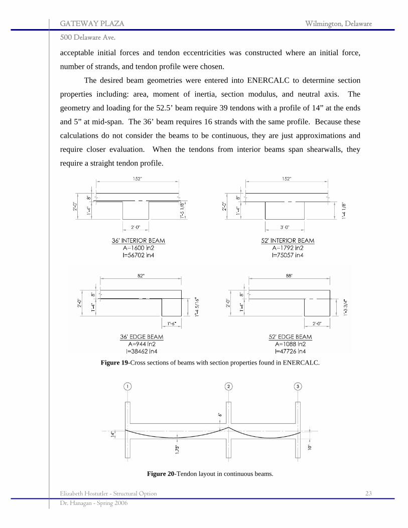
The desired beam geometries were entered into ENERCALC to determine section
properties including: area, moment of inertia, section modulus, and neutral axis. The
geometry and loading for the 52.5’ beam require 39 tendons with a profile of 14” at the ends
and 5” at mid-span. The 36’ beam requires 16 strands with the same profile. Because these
calculations do not consider the beams to be continuous, they are just approximations and
require closer evaluation. When the tendons from interior beams span shearwalls, they
require a straight tendon profile.
Figure 19-Cross sections of beams with section properties found in ENERCALC.
Figure 20-Tendon layout in continuous beams.
GATEWAY PLAZA Wilmington, Delaware
500 Delaware Ave.
Elizabeth Hostutler - Structural Option 24 Dr. Hanagan - Spring 2006
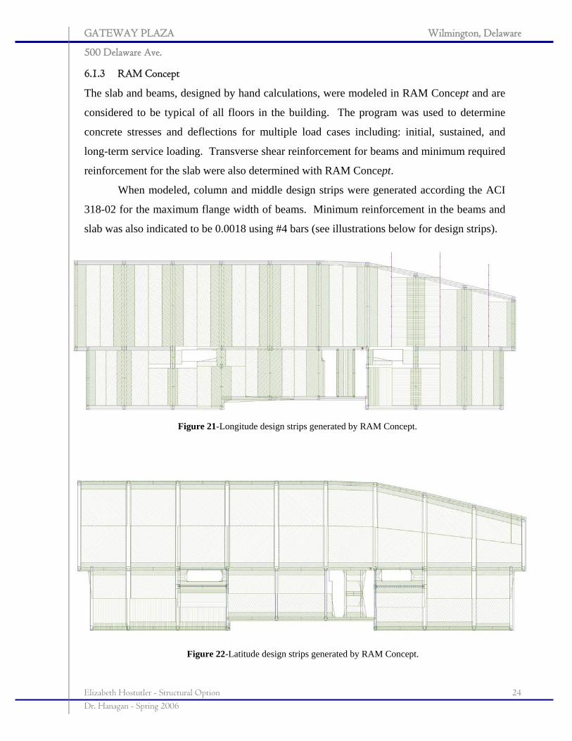
6.1.3 RAM Concept
The slab and beams, designed by hand calculations, were modeled in RAM Concept and are
considered to be typical of all floors in the building. The program was used to determine
concrete stresses and deflections for multiple load cases including: initial, sustained, and
long-term service loading. Transverse shear reinforcement for beams and minimum required
reinforcement for the slab were also determined with RAM Concept.
When modeled, column and middle design strips were generated according the ACI
318-02 for the maximum flange width of beams. Minimum reinforcement in the beams and
slab was also indicated to be 0.0018 using #4 bars (see illustrations below for design strips).
Figure 21-Longitude design strips generated by RAM Concept.
Figure 22-Latitude design strips generated by RAM Concept.
GATEWAY PLAZA Wilmington, Delaware
500 Delaware Ave.
Elizabeth Hostutler - Structural Option 25 Dr. Hanagan - Spring 2006
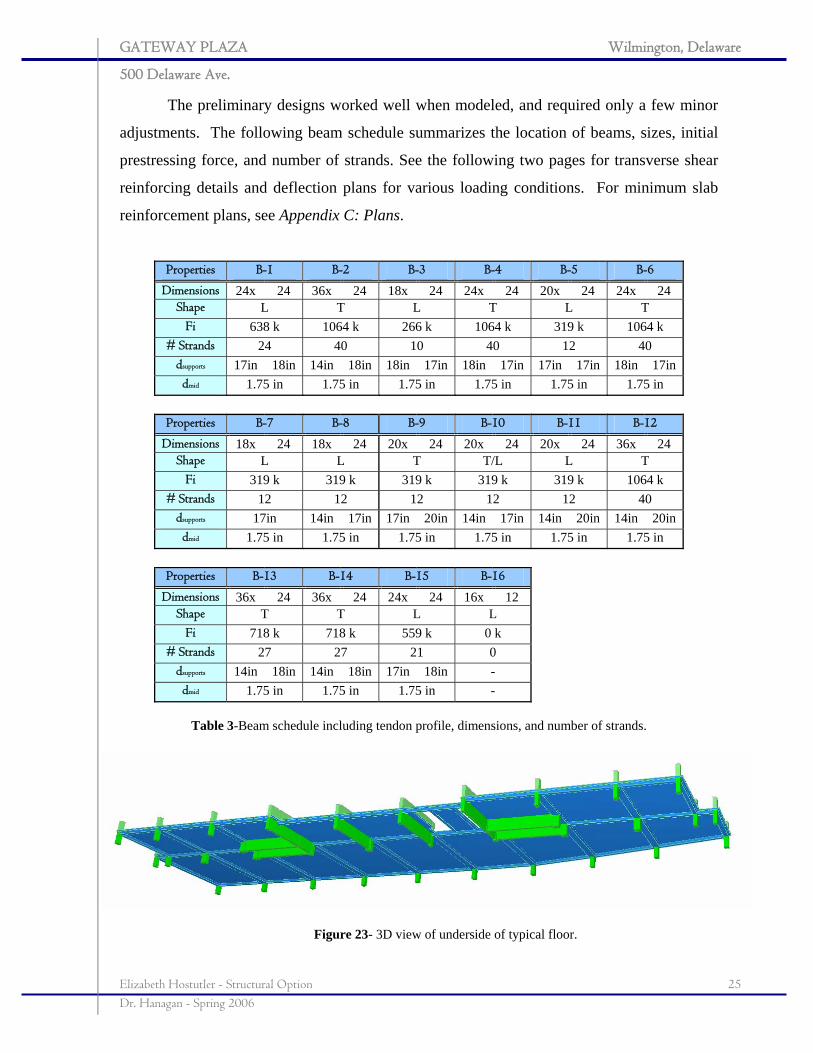
The preliminary designs worked well when modeled, and required only a few minor
adjustments. The following beam schedule summarizes the location of beams, sizes, initial
prestressing force, and number of strands. See the following two pages for transverse shear
reinforcing details and deflection plans for various loading conditions. For minimum slab
reinforcement plans, see Appendix C: Plans.
Properties B-1 B-2 B-3 B-4 B-5 B-6
Dimensions 24x 24 36x 24 18x 24 24x 24 20x 24 24x 24 Shape L T L T L T
Fi 638 k 1064 k 266 k 1064 k 319 k 1064 k # Strands 24 40 10 40 12 40
dsupports 17in 18in 14in 18in 18in 17in 18in 17in 17in 17in 18in 17indmid 1.75 in 1.75 in 1.75 in 1.75 in 1.75 in 1.75 in
Properties B-7 B-8 B-9 B-10 B-11 B-12
Dimensions 18x 24 18x 24 20x 24 20x 24 20x 24 36x 24 Shape L L T T/L L T
Fi 319 k 319 k 319 k 319 k 319 k 1064 k # Strands 12 12 12 12 12 40
dsupports 17in 14in 17in 17in 20in 14in 17in 14in 20in 14in 20indmid 1.75 in 1.75 in 1.75 in 1.75 in 1.75 in 1.75 in
Properties B-13 B-14 B-15 B-16
Dimensions 36x 24 36x 24 24x 24 16x 12 Shape T T L L
Fi 718 k 718 k 559 k 0 k # Strands 27 27 21 0
dsupports 14in 18in 14in 18in 17in 18in - dmid 1.75 in 1.75 in 1.75 in -
Table 3-Beam schedule including tendon profile, dimensions, and number of strands.
Figure 23- 3D view of underside of typical floor.
GATEWAY PLAZA Wilmington, Delaware
500 Delaware Ave.
Elizabeth Hostutler - Structural Option 26 Dr. Hanagan - Spring 2006
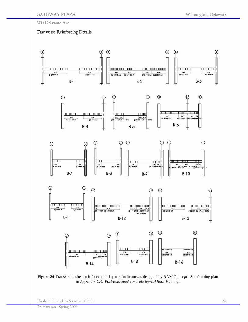
Transverse Reinforcing Details
Figure 24-Transverse, shear reinforcement layouts for beams as designed by RAM Concept. See framing plan
in Appendix C.4: Post-tensioned concrete typical floor framing.
GATEWAY PLAZA Wilmington, Delaware
500 Delaware Ave.
Elizabeth Hostutler - Structural Option 27 Dr. Hanagan - Spring 2006
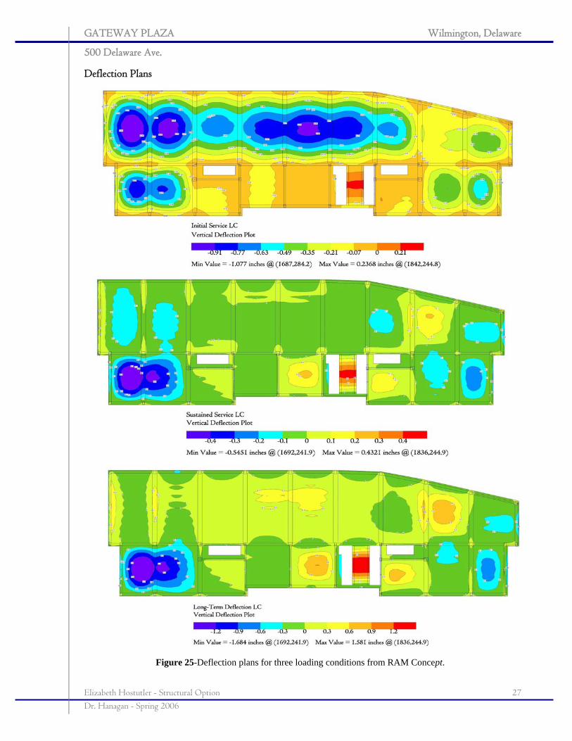
Deflection Plans
Figure 25-Deflection plans for three loading conditions from RAM Concept.
GATEWAY PLAZA Wilmington, Delaware
500 Delaware Ave.
Elizabeth Hostutler - Structural Option 28 Dr. Hanagan - Spring 2006
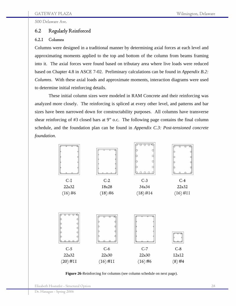
6.2 Regularly Reinforced
6.2.1 Columns Columns were designed in a traditional manner by determining axial forces at each level and
approximating moments applied to the top and bottom of the column from beams framing
into it. The axial forces were found based on tributary area where live loads were reduced
based on Chapter 4.8 in ASCE 7-02. Preliminary calculations can be found in Appendix B.2:
Columns. With these axial loads and approximate moments, interaction diagrams were used
to determine initial reinforcing details.
These initial column sizes were modeled in RAM Concrete and their reinforcing was
analyzed more closely. The reinforcing is spliced at every other level, and patterns and bar
sizes have been narrowed down for constructability purposes. All columns have transverse
shear reinforcing of #3 closed bars at 9” o.c. The following page contains the final column
schedule, and the foundation plan can be found in Appendix C.3: Post-tensioned concrete
foundation.
Figure 26-Reinforcing for columns (see column schedule on next page).
GATEWAY PLAZA Wilmington, Delaware
500 Delaware Ave.
Elizabeth Hostutler - Structural Option 29 Dr. Hanagan - Spring 2006
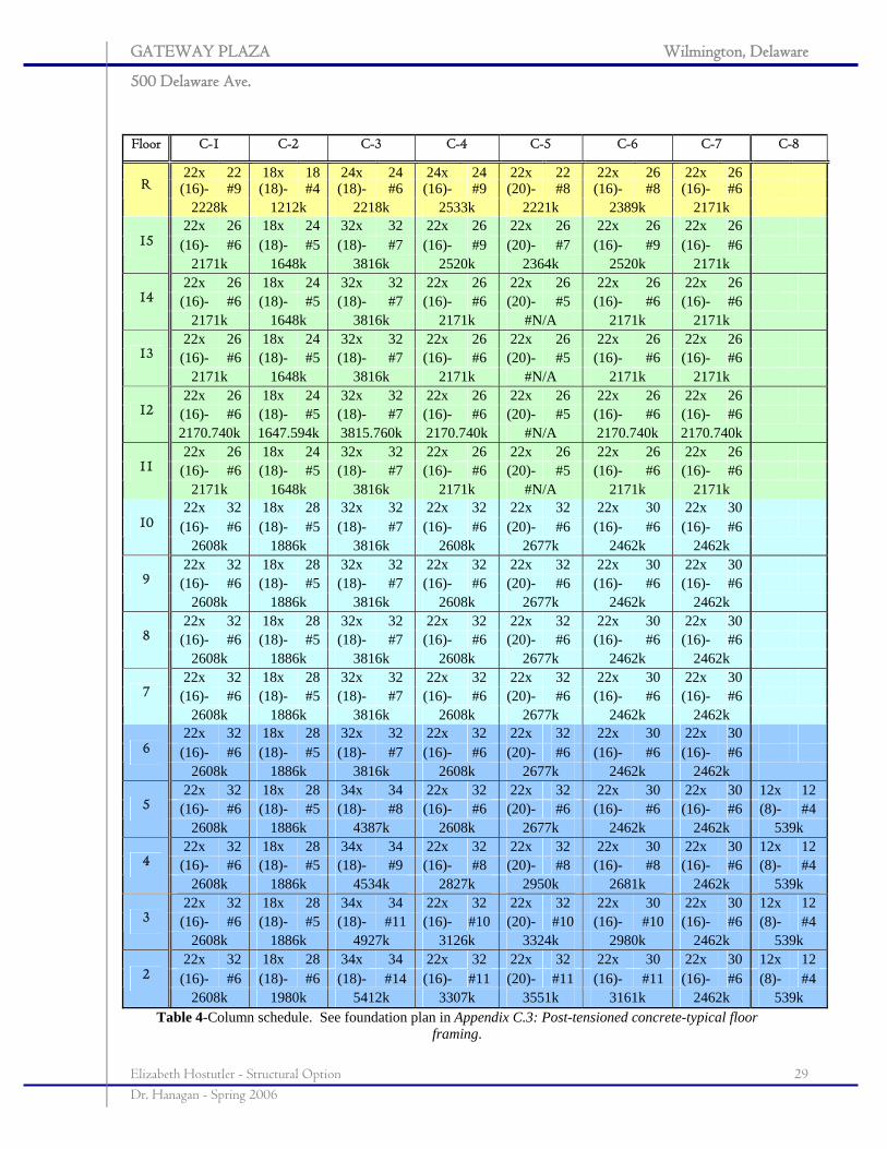
Floor C-1 C-2 C-3 C-4 C-5 C-6 C-7 C-8
22x 22 18x 18 24x 24 24x 24 22x 22 22x 26 22x 26(16)- #9 (18)- #4 (18)- #6 (16)- #9 (20)- #8 (16)- #8 (16)- #6 R
2228k 1212k 2218k 2533k 2221k 2389k 2171k 22x 26 18x 24 32x 32 22x 26 22x 26 22x 26 22x 26
(16)- #6 (18)- #5 (18)- #7 (16)- #9 (20)- #7 (16)- #9 (16)- #6 15
2171k 1648k 3816k 2520k 2364k 2520k 2171k 22x 26 18x 24 32x 32 22x 26 22x 26 22x 26 22x 26
(16)- #6 (18)- #5 (18)- #7 (16)- #6 (20)- #5 (16)- #6 (16)- #6 14
2171k 1648k 3816k 2171k #N/A 2171k 2171k 22x 26 18x 24 32x 32 22x 26 22x 26 22x 26 22x 26
(16)- #6 (18)- #5 (18)- #7 (16)- #6 (20)- #5 (16)- #6 (16)- #6 13
2171k 1648k 3816k 2171k #N/A 2171k 2171k 22x 26 18x 24 32x 32 22x 26 22x 26 22x 26 22x 26
(16)- #6 (18)- #5 (18)- #7 (16)- #6 (20)- #5 (16)- #6 (16)- #6 12
2170.740k 1647.594k 3815.760k 2170.740k #N/A 2170.740k 2170.740k 22x 26 18x 24 32x 32 22x 26 22x 26 22x 26 22x 26
(16)- #6 (18)- #5 (18)- #7 (16)- #6 (20)- #5 (16)- #6 (16)- #6 11
2171k 1648k 3816k 2171k #N/A 2171k 2171k 22x 32 18x 28 32x 32 22x 32 22x 32 22x 30 22x 30
(16)- #6 (18)- #5 (18)- #7 (16)- #6 (20)- #6 (16)- #6 (16)- #6 10
2608k 1886k 3816k 2608k 2677k 2462k 2462k 22x 32 18x 28 32x 32 22x 32 22x 32 22x 30 22x 30
(16)- #6 (18)- #5 (18)- #7 (16)- #6 (20)- #6 (16)- #6 (16)- #6 9
2608k 1886k 3816k 2608k 2677k 2462k 2462k 22x 32 18x 28 32x 32 22x 32 22x 32 22x 30 22x 30
(16)- #6 (18)- #5 (18)- #7 (16)- #6 (20)- #6 (16)- #6 (16)- #6 8
2608k 1886k 3816k 2608k 2677k 2462k 2462k 22x 32 18x 28 32x 32 22x 32 22x 32 22x 30 22x 30
(16)- #6 (18)- #5 (18)- #7 (16)- #6 (20)- #6 (16)- #6 (16)- #6 7
2608k 1886k 3816k 2608k 2677k 2462k 2462k 22x 32 18x 28 32x 32 22x 32 22x 32 22x 30 22x 30
(16)- #6 (18)- #5 (18)- #7 (16)- #6 (20)- #6 (16)- #6 (16)- #6 6
2608k 1886k 3816k 2608k 2677k 2462k 2462k 22x 32 18x 28 34x 34 22x 32 22x 32 22x 30 22x 30 12x 12
(16)- #6 (18)- #5 (18)- #8 (16)- #6 (20)- #6 (16)- #6 (16)- #6 (8)- #4 5
2608k 1886k 4387k 2608k 2677k 2462k 2462k 539k 22x 32 18x 28 34x 34 22x 32 22x 32 22x 30 22x 30 12x 12
(16)- #6 (18)- #5 (18)- #9 (16)- #8 (20)- #8 (16)- #8 (16)- #6 (8)- #4 4
2608k 1886k 4534k 2827k 2950k 2681k 2462k 539k 22x 32 18x 28 34x 34 22x 32 22x 32 22x 30 22x 30 12x 12
(16)- #6 (18)- #5 (18)- #11 (16)- #10 (20)- #10 (16)- #10 (16)- #6 (8)- #4 3
2608k 1886k 4927k 3126k 3324k 2980k 2462k 539k 22x 32 18x 28 34x 34 22x 32 22x 32 22x 30 22x 30 12x 12
(16)- #6 (18)- #6 (18)- #14 (16)- #11 (20)- #11 (16)- #11 (16)- #6 (8)- #4 2
2608k 1980k 5412k 3307k 3551k 3161k 2462k 539k Table 4-Column schedule. See foundation plan in Appendix C.3: Post-tensioned concrete-typical floor
framing.
GATEWAY PLAZA Wilmington, Delaware
500 Delaware Ave.
Elizabeth Hostutler - Structural Option 30 Dr. Hanagan - Spring 2006
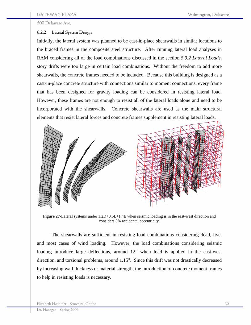
6.2.2 Lateral System Design
Initially, the lateral system was planned to be cast-in-place shearwalls in similar locations to
the braced frames in the composite steel structure. After running lateral load analyses in
RAM considering all of the load combinations discussed in the section 5.3.2 Lateral Loads,
story drifts were too large in certain load combinations. Without the freedom to add more
shearwalls, the concrete frames needed to be included. Because this building is designed as a
cast-in-place concrete structure with connections similar to moment connections, every frame
that has been designed for gravity loading can be considered in resisting lateral load.
However, these frames are not enough to resist all of the lateral loads alone and need to be
incorporated with the shearwalls. Concrete shearwalls are used as the main structural
elements that resist lateral forces and concrete frames supplement in resisting lateral loads.
Figure 27-Lateral systems under 1.2D+0.5L+1.4E when seismic loading is in the east-west direction and
considers 5% accidental eccentricity.
The shearwalls are sufficient in resisting load combinations considering dead, live,
and most cases of wind loading. However, the load combinations considering seismic
loading introduce large deflections, around 12” when load is applied in the east-west
direction, and torsional problems, around 1.15°. Since this drift was not drastically decreased
by increasing wall thickness or material strength, the introduction of concrete moment frames
to help in resisting loads is necessary.
GATEWAY PLAZA Wilmington, Delaware
500 Delaware Ave.
Elizabeth Hostutler - Structural Option 31 Dr. Hanagan - Spring 2006
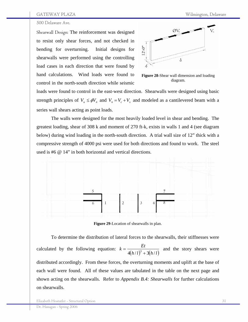
Shearwall Design: The reinforcement was designed
to resist only shear forces, and not checked in
bending for overturning. Initial designs for
shearwalls were performed using the controlling
load cases in each direction that were found by
hand calculations. Wind loads were found to
control in the north-south direction while seismic
loads were found to control in the east-west direction. Shearwalls were designed using basic
strength principles of nu VV φ≤ and scn VVV += and modeled as a cantilevered beam with a
series wall shears acting as point loads.
The walls were designed for the most heavily loaded level in shear and bending. The
greatest loading, shear of 308 k and moment of 270 ft-k, exists in walls 1 and 4 (see diagram
below) during wind loading in the north-south direction. A trial wall size of 12” thick with a
compressive strength of 4000 psi were used for both directions and found to work. The steel
used is #6 @ 14” in both horizontal and vertical directions.
Figure 29-Location of shearwalls in plan.
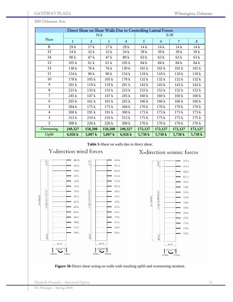
To determine the distribution of lateral forces to the shearwalls, their stiffnesses were
calculated by the following equation: ( ) ( )lhlh
Etk/3/4 3 +
= and the story shears were
distributed accordingly. From these forces, the overturning moments and uplift at the base of
each wall were found. All of these values are tabulated in the table on the next page and
shown acting on the shearwalls. Refer to Appendix B.4: Shearwalls for further calculations
on shearwalls.
Figure 28-Shear wall dimension and loading diagram.
GATEWAY PLAZA Wilmington, Delaware
500 Delaware Ave.
Elizabeth Hostutler - Structural Option 32 Dr. Hanagan - Spring 2006
Direct Shear on Shear Walls Due to Controlling Lateral Forces N-S E-W
Floor 1 2 3 4 5 6 7 8 R 29 k 17 k 17 k 29 k 14 k 14 k 14 k 14 k 15 54 k 32 k 32 k 54 k 39 k 39 k 39 k 39 k 14 80 k 47 k 47 k 80 k 63 k 63 k 63 k 63 k 13 105 k 61 k 61 k 105 k 84 k 84 k 84 k 84 k 12 130 k 76 k 76 k 130 k 102 k 102 k 102 k 102 k 11 154 k 90 k 90 k 154 k 118 k 118 k 118 k 118 k 10 178 k 105 k 105 k 178 k 132 k 132 k 132 k 132 k 9 201 k 119 k 119 k 201 k 143 k 143 k 143 k 143 k 8 223 k 133 k 133 k 223 k 152 k 152 k 152 k 152 k 7 245 k 147 k 147 k 245 k 160 k 160 k 160 k 160 k 6 265 k 161 k 161 k 265 k 166 k 166 k 166 k 166 k 5 284 k 175 k 175 k 284 k 170 k 170 k 170 k 170 k 4 300 k 191 k 191 k 300 k 173 k 173 k 173 k 173 k 3 312 k 210 k 210 k 312 k 175 k 175 k 175 k 175 k 2 308 k 226 k 226 k 308 k 176 k 176 k 176 k 176 k
Overturning 249,327 150,208 150,208 249,327 172,127 172,127 172,127 172,127 Uplift 6,926 k 5,007 k 5,007 k 6,926 k 5,738 k 5,738 k 5,738 k 5,738 k
Table 5-Shear on walls due to direct shear.
Figure 30-Direct shear acting on walls with resulting uplift and overturning moment.
GATEWAY PLAZA Wilmington, Delaware
500 Delaware Ave.
Elizabeth Hostutler - Structural Option 33 Dr. Hanagan - Spring 2006
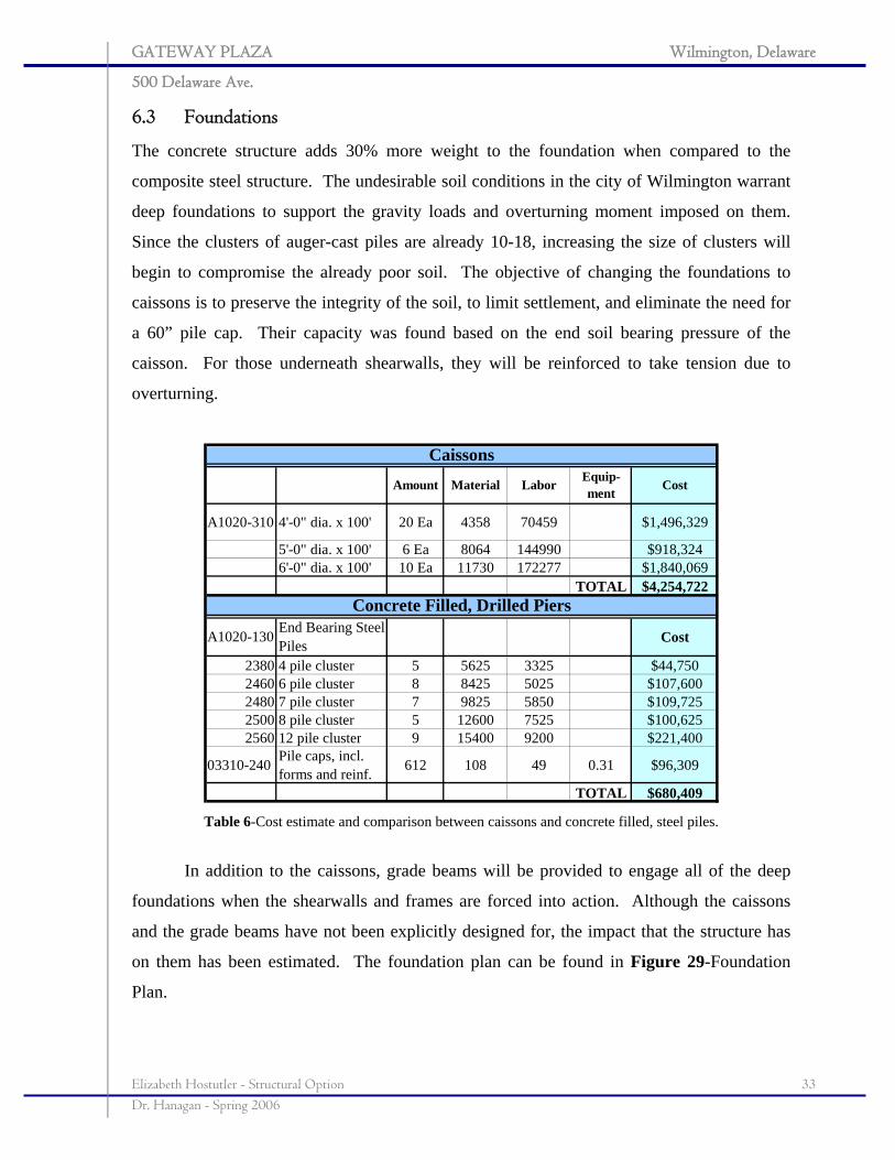
6.3 Foundations
The concrete structure adds 30% more weight to the foundation when compared to the
composite steel structure. The undesirable soil conditions in the city of Wilmington warrant
deep foundations to support the gravity loads and overturning moment imposed on them.
Since the clusters of auger-cast piles are already 10-18, increasing the size of clusters will
begin to compromise the already poor soil. The objective of changing the foundations to
caissons is to preserve the integrity of the soil, to limit settlement, and eliminate the need for
a 60” pile cap. Their capacity was found based on the end soil bearing pressure of the
caisson. For those underneath shearwalls, they will be reinforced to take tension due to
overturning.
Amount Material Labor Equip-ment Cost
A1020-310 4'-0" dia. x 100' 20 Ea 4358 70459 $1,496,329
5'-0" dia. x 100' 6 Ea 8064 144990 $918,3246'-0" dia. x 100' 10 Ea 11730 172277 $1,840,069
TOTAL $4,254,722
A1020-130 End Bearing Steel Piles Cost
2380 4 pile cluster 5 5625 3325 $44,7502460 6 pile cluster 8 8425 5025 $107,6002480 7 pile cluster 7 9825 5850 $109,7252500 8 pile cluster 5 12600 7525 $100,6252560 12 pile cluster 9 15400 9200 $221,400
03310-240 Pile caps, incl. forms and reinf. 612 108 49 0.31 $96,309
TOTAL $680,409
Caissons
Concrete Filled, Drilled Piers
Table 6-Cost estimate and comparison between caissons and concrete filled, steel piles.
In addition to the caissons, grade beams will be provided to engage all of the deep
foundations when the shearwalls and frames are forced into action. Although the caissons
and the grade beams have not been explicitly designed for, the impact that the structure has
on them has been estimated. The foundation plan can be found in Figure 29-Foundation
Plan.
GATEWAY PLAZA Wilmington, Delaware
500 Delaware Ave.
Elizabeth Hostutler - Structural Option 34 Dr. Hanagan - Spring 2006
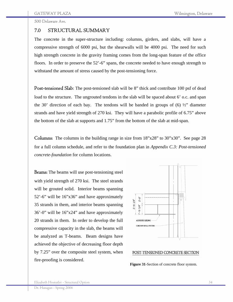
7.0 STRUCTURAL SUMMARY
The concrete in the super-structure including: columns, girders, and slabs, will have a
compressive strength of 6000 psi, but the shearwalls will be 4000 psi. The need for such
high strength concrete in the gravity framing comes from the long-span feature of the office
floors. In order to preserve the 52’-6” spans, the concrete needed to have enough strength to
withstand the amount of stress caused by the post-tensioning force.
Post-tensioned Slab: The post-tensioned slab will be 8” thick and contribute 100 psf of dead
load to the structure. The ungrouted tendons in the slab will be spaced about 6’ o.c. and span
the 30’ direction of each bay. The tendons will be banded in groups of (6) ½” diameter
strands and have yield strength of 270 ksi. They will have a parabolic profile of 6.75” above
the bottom of the slab at supports and 1.75” from the bottom of the slab at mid-span.
Columns: The columns in the building range in size from 18”x28” to 30”x30”. See page 28
for a full column schedule, and refer to the foundation plan in Appendix C.3: Post-tensioned
concrete-foundation for column locations.
Beams: The beams will use post-tensioning steel
with yield strength of 270 ksi. The steel strands
will be grouted solid. Interior beams spanning
52’-6” will be 16”x36” and have approximately
35 strands in them, and interior beams spanning
36’-0” will be 16”x24” and have approximately
20 strands in them. In order to develop the full
compressive capacity in the slab, the beams will
be analyzed as T-beams. Beam designs have
achieved the objective of decreasing floor depth
by 7.25” over the composite steel system, when
fire-proofing is considered. Figure 31-Section of concrete floor system.
GATEWAY PLAZA Wilmington, Delaware
500 Delaware Ave.
Elizabeth Hostutler - Structural Option 35 Dr. Hanagan - Spring 2006
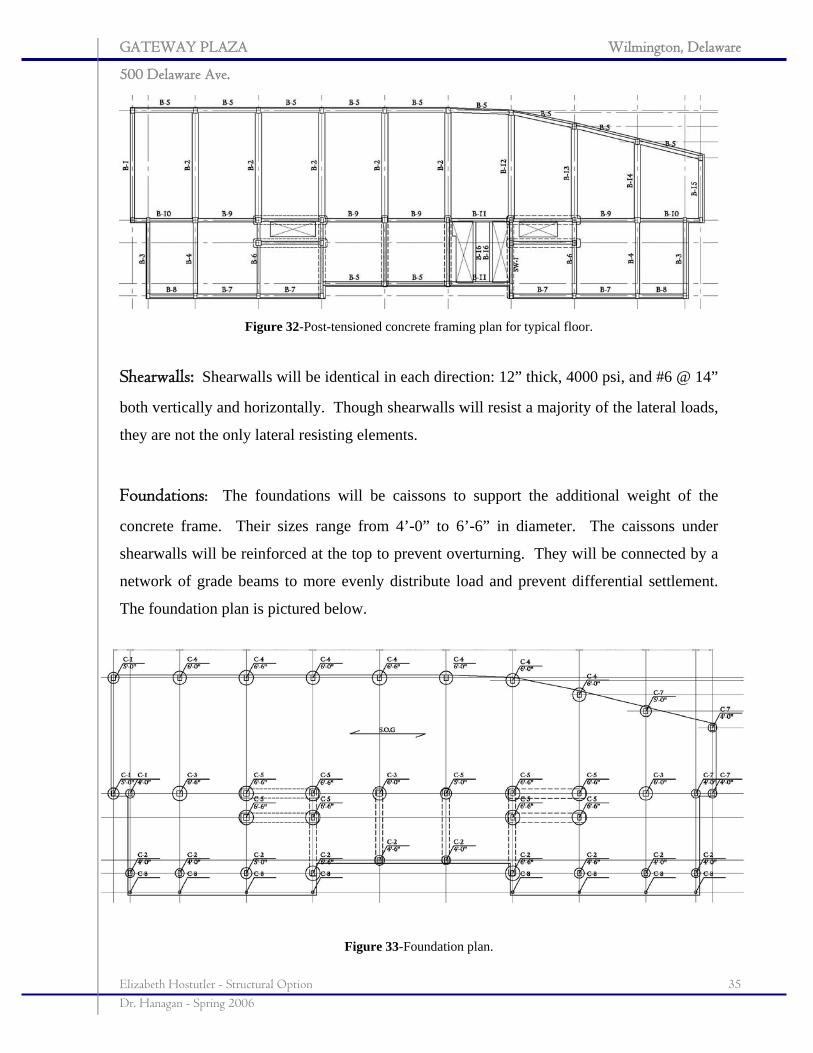
Figure 32-Post-tensioned concrete framing plan for typical floor.
Shearwalls: Shearwalls will be identical in each direction: 12” thick, 4000 psi, and #6 @ 14”
both vertically and horizontally. Though shearwalls will resist a majority of the lateral loads,
they are not the only lateral resisting elements.
Foundations: The foundations will be caissons to support the additional weight of the
concrete frame. Their sizes range from 4’-0” to 6’-6” in diameter. The caissons under
shearwalls will be reinforced at the top to prevent overturning. They will be connected by a
network of grade beams to more evenly distribute load and prevent differential settlement.
The foundation plan is pictured below.
Figure 33-Foundation plan.
GATEWAY PLAZA Wilmington, Delaware
500 Delaware Ave.
Elizabeth Hostutler - Structural Option 36 Dr. Hanagan - Spring 2006
8.0 BREADTH STUDIES
The post-tension concrete design of Gateway Plaza will have an impact on all of the systems
in the building, including the construction of the project. In particular, this report will focus
on how supply air ducts, part of the mechanical system, can be designed according to
ASHRAE Standard 62.1 and how the project can be scheduled efficiently.
8.1 Mechanical Study
The main goal of the mechanical study is to design supply and return air ducts in a typical
floor in Gateway Plaza. To keep with the objective of the structural design, minimizing floor
depth, these ducts will be designed to minimize their depth. Since the building is for tenant
fit-out, there is no existing duct plan to compare. However, the riser on each floor has a main
supply duct with a depth of 26”. To handle air return, the ceiling will be used as a plenum
for collecting return air, a system that works well when drop ceilings are used. The
mechanical room is equipped with two 90”x32” grilles to pull in air from the plenum, and the
room has a louver to exhaust air outside.
8.1.1 Indoor Air Quality
Before ducts could be laid out, it is necessary to check that the building is receiving the
required amount of outdoor air for proper ventilation. The layout for the new structural
system was designed according to ASHRAE Standard 62.1: Ventilation for Acceptable
Indoor Air Quality using the Ventilation Rate Procedure laid out in section 6.2. This
procedure “determines outdoor air intake rates based on space type, occupancy level, and
floor area.” The actual amount of outdoor air supplied by the mechanical equipment has
been compared to the minimum amount of outdoor air intake typical of the office floor
(shown on the next page) as determined by the above procedure.
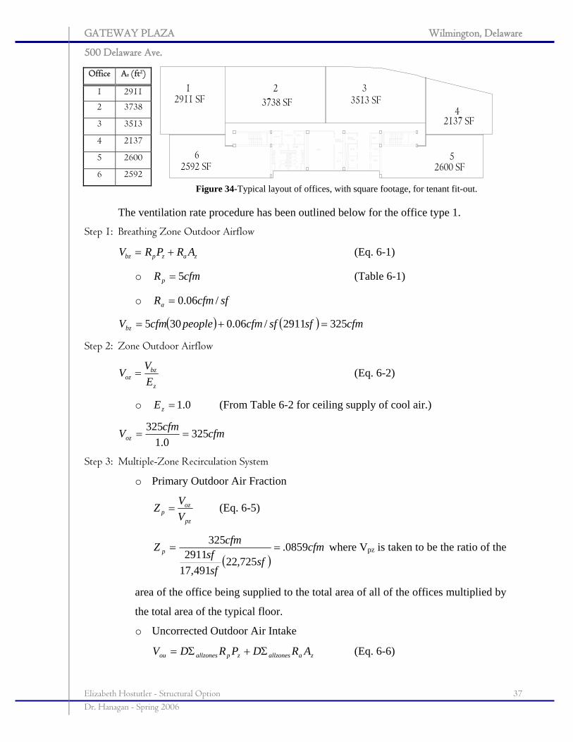
Since the building is for tenant fit-out, a basic design was established where the
typical office floor was subdivided into five separate offices, seen in the diagram below. To
estimate the occupancy of each office, it was assumed that each person occupied a 10’x10’
cubicle, or 100 ft2, including hallway circulation space.
GATEWAY PLAZA Wilmington, Delaware
500 Delaware Ave.
Elizabeth Hostutler - Structural Option 37 Dr. Hanagan - Spring 2006
Office Az (ft2)
1 2911
2 3738
3 3513
4 2137
5 2600
6 2592
The ventilation rate procedure has been outlined below for the office type 1.
Step 1: Breathing Zone Outdoor Airflow
zazpbz ARPRV += (Eq. 6-1)
o cfmRp 5= (Table 6-1)
o sfcfmRa /06.0=
( ) ( ) cfmsfsfcfmpeoplecfmVbz 3252911/06.0305 =+=
Step 2: Zone Outdoor Airflow
z
bzoz E
VV = (Eq. 6-2)
o 0.1=zE (From Table 6-2 for ceiling supply of cool air.)
cfmcfmVoz 3250.1
325==
Step 3: Multiple-Zone Recirculation System
o Primary Outdoor Air Fraction
pz
ozp V
VZ = (Eq. 6-5)
( )cfm
sfsf
sfcfmZ p 0859.
725,22491,17
2911325
== where Vpz is taken to be the ratio of the
area of the office being supplied to the total area of all of the offices multiplied by
the total area of the typical floor.
o Uncorrected Outdoor Air Intake
zaallzoneszpallzonesou ARDPRDV Σ+Σ= (Eq. 6-6)
Figure 34-Typical layout of offices, with square footage, for tenant fit-out.
GATEWAY PLAZA Wilmington, Delaware
500 Delaware Ave.
Elizabeth Hostutler - Structural Option 38 Dr. Hanagan - Spring 2006
• The occupancy diversity is taken to be 1.0, which is conservative,
because each office is being designed as having the same occupancy
requirements.
cfmVou 325=
o Outdoor Air Intake
v
ouot E
VV =
• Ventilation Efficiency: 0.1=vE because 15.0<pZ .
cfmVot 325=
Step 4: Outdoor Air Comparison
After all of the spaces have been calculated, the total amount of outdoor air that must
be supplied to office space #1 is found to be 1942 cfm (see Appendix D.1 Mechanical for
calculation of all spaces). This value is greatly less than the 4545 cfm that is supplied to the
area by the existing equipment. Therefore, the typical office floor is capable of handling the
ventilation requirements. This oversize is to be expected for a tenant fit-out space where
space requirements are unknown.
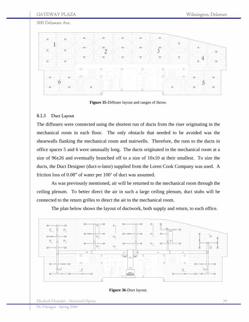
8.1.2 Diffuser Layout
Since the requirements for each office space have been found according to ASHRAE
Standard 62.1, the ducts can be laid out to achieve the necessary supply loads. Assuming
that each supply diffuser will have a throw range of a 6’-16’ radius, the diffusers can be laid
out for each office space, taking care to cover the entire area. The diffusers specified by the
architect are 24”x24” so that they will fit into the 24”x48” acoustic ceiling grid. See the
diagram below for the preliminary diffuser lay-out and the throw area.
Return grills have been laid out in such a manner to create a natural circulation of air.
The returns, about three supplies to each return, have been positioned between rows of
supply diffusers. While the air will be supplied to the offices through forced air, ceiling
plenum return will bring air back to the mechanical room.
GATEWAY PLAZA Wilmington, Delaware
500 Delaware Ave.
Elizabeth Hostutler - Structural Option 39 Dr. Hanagan - Spring 2006
Figure 35-Diffuser layout and ranges of throw.
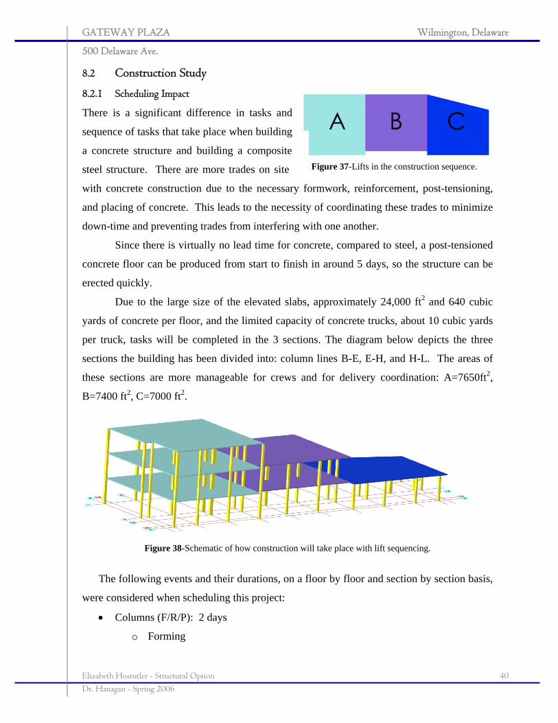
8.1.3 Duct Layout
The diffusers were connected using the shortest run of ducts from the riser originating in the
mechanical room in each floor. The only obstacle that needed to be avoided was the
shearwalls flanking the mechanical room and stairwells. Therefore, the runs to the ducts in
office spaces 5 and 6 were unusually long. The ducts originated in the mechanical room at a
size of 96x26 and eventually branched off to a size of 10x10 at their smallest. To size the
ducts, the Duct Designer (duct-o-lator) supplied from the Loren Cook Company was used. A
friction loss of 0.08” of water per 100’ of duct was assumed.
As was previously mentioned, air will be returned to the mechanical room through the
ceiling plenum. To better direct the air in such a large ceiling plenum, duct stubs will be
connected to the return grilles to direct the air to the mechanical room.
The plan below shows the layout of ductwork, both supply and return, to each office.
Figure 36-Duct layout.
GATEWAY PLAZA Wilmington, Delaware
500 Delaware Ave.
Elizabeth Hostutler - Structural Option 40 Dr. Hanagan - Spring 2006
8.2 Construction Study
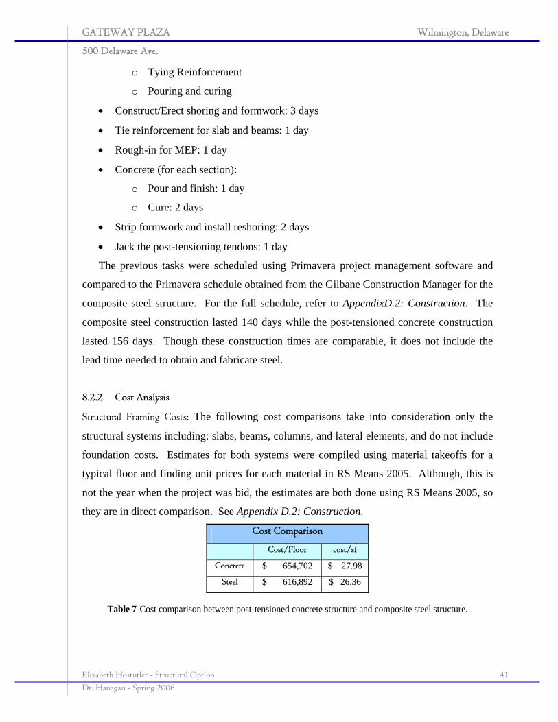
8.2.1 Scheduling Impact
There is a significant difference in tasks and
sequence of tasks that take place when building
a concrete structure and building a composite
steel structure. There are more trades on site
with concrete construction due to the necessary formwork, reinforcement, post-tensioning,
and placing of concrete. This leads to the necessity of coordinating these trades to minimize
down-time and preventing trades from interfering with one another.
Since there is virtually no lead time for concrete, compared to steel, a post-tensioned
concrete floor can be produced from start to finish in around 5 days, so the structure can be
erected quickly.
Due to the large size of the elevated slabs, approximately 24,000 ft2 and 640 cubic
yards of concrete per floor, and the limited capacity of concrete trucks, about 10 cubic yards
per truck, tasks will be completed in the 3 sections. The diagram below depicts the three
sections the building has been divided into: column lines B-E, E-H, and H-L. The areas of
these sections are more manageable for crews and for delivery coordination: A=7650ft2,
B=7400 ft2, C=7000 ft2.
Figure 38-Schematic of how construction will take place with lift sequencing.
The following events and their durations, on a floor by floor and section by section basis,
were considered when scheduling this project:
• Columns (F/R/P): 2 days
o Forming
Figure 37-Lifts in the construction sequence.
GATEWAY PLAZA Wilmington, Delaware
500 Delaware Ave.
Elizabeth Hostutler - Structural Option 41 Dr. Hanagan - Spring 2006
o Tying Reinforcement
o Pouring and curing
• Construct/Erect shoring and formwork: 3 days
• Tie reinforcement for slab and beams: 1 day
• Rough-in for MEP: 1 day
• Concrete (for each section):
o Pour and finish: 1 day
o Cure: 2 days
• Strip formwork and install reshoring: 2 days
• Jack the post-tensioning tendons: 1 day
The previous tasks were scheduled using Primavera project management software and
compared to the Primavera schedule obtained from the Gilbane Construction Manager for the
composite steel structure. For the full schedule, refer to AppendixD.2: Construction. The
composite steel construction lasted 140 days while the post-tensioned concrete construction
lasted 156 days. Though these construction times are comparable, it does not include the
lead time needed to obtain and fabricate steel.
8.2.2 Cost Analysis
Structural Framing Costs: The following cost comparisons take into consideration only the
structural systems including: slabs, beams, columns, and lateral elements, and do not include
foundation costs. Estimates for both systems were compiled using material takeoffs for a
typical floor and finding unit prices for each material in RS Means 2005. Although, this is
not the year when the project was bid, the estimates are both done using RS Means 2005, so
they are in direct comparison. See Appendix D.2: Construction.
Cost Comparison
Cost/Floor cost/sf
Concrete $ 654,702 $ 27.98
Steel $ 616,892 $ 26.36
Table 7-Cost comparison between post-tensioned concrete structure and composite steel structure.
GATEWAY PLAZA Wilmington, Delaware
500 Delaware Ave.
Elizabeth Hostutler - Structural Option 42 Dr. Hanagan - Spring 2006
0
20
40
60
80
100
120
140
160
1
Duration (days )
Duration Comparison
Concrete
S teel
$0.00
$5.00
$10.00
$15.00
$20.00
$25.00
$30.00
1
Cos t/s f
Price Comparison
Concre te
Stee l
$0
$500,000
$1,000,000
$1,500,000
$2,000,000$2,500,000
$3,000,000
$3,500,000
$4,000,000$4,500,000
1
Cos t
Foundation Cost Comparison
Concrete
S teel
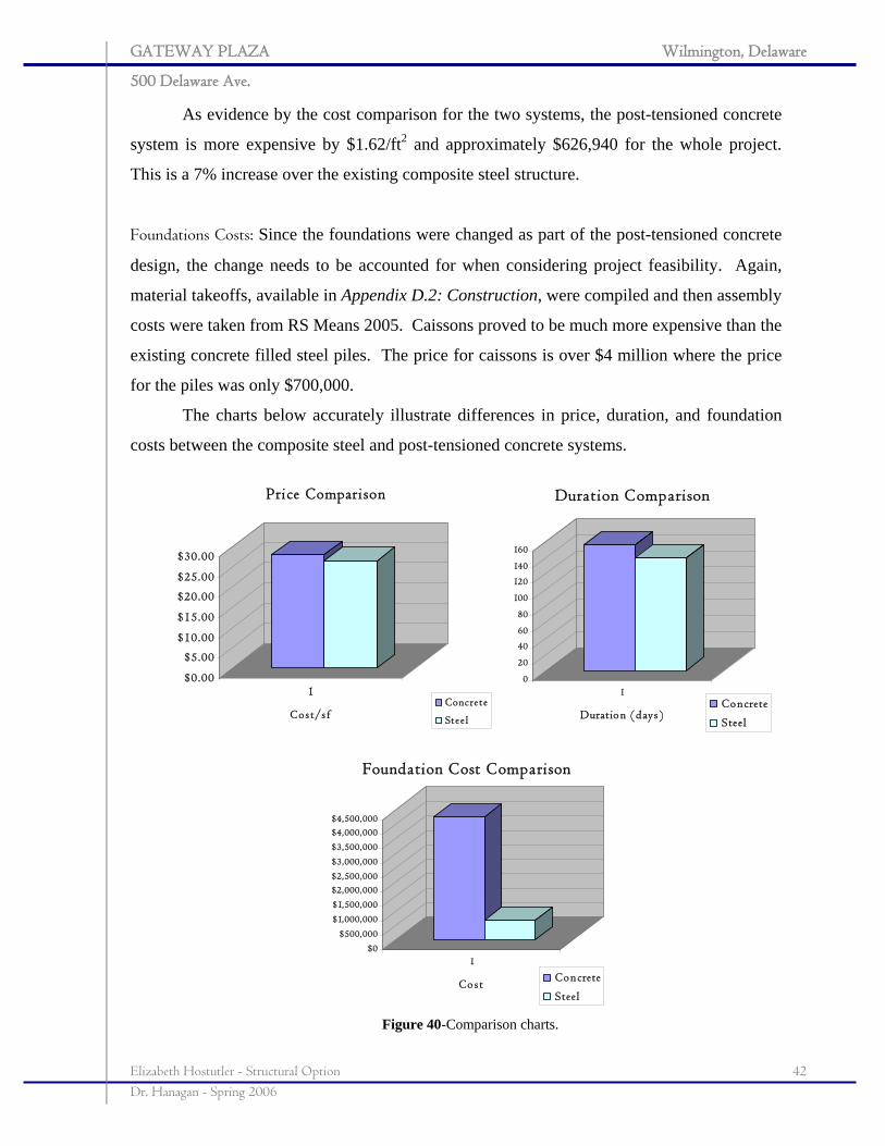
As evidence by the cost comparison for the two systems, the post-tensioned concrete
system is more expensive by $1.62/ft2 and approximately $626,940 for the whole project.
This is a 7% increase over the existing composite steel structure.
Foundations Costs: Since the foundations were changed as part of the post-tensioned concrete
design, the change needs to be accounted for when considering project feasibility. Again,
material takeoffs, available in Appendix D.2: Construction, were compiled and then assembly
costs were taken from RS Means 2005. Caissons proved to be much more expensive than the
existing concrete filled steel piles. The price for caissons is over $4 million where the price
for the piles was only $700,000.
The charts below accurately illustrate differences in price, duration, and foundation
costs between the composite steel and post-tensioned concrete systems.
Figure 40-Comparison charts.
GATEWAY PLAZA Wilmington, Delaware
500 Delaware Ave.
Elizabeth Hostutler - Structural Option 43 Dr. Hanagan - Spring 2006
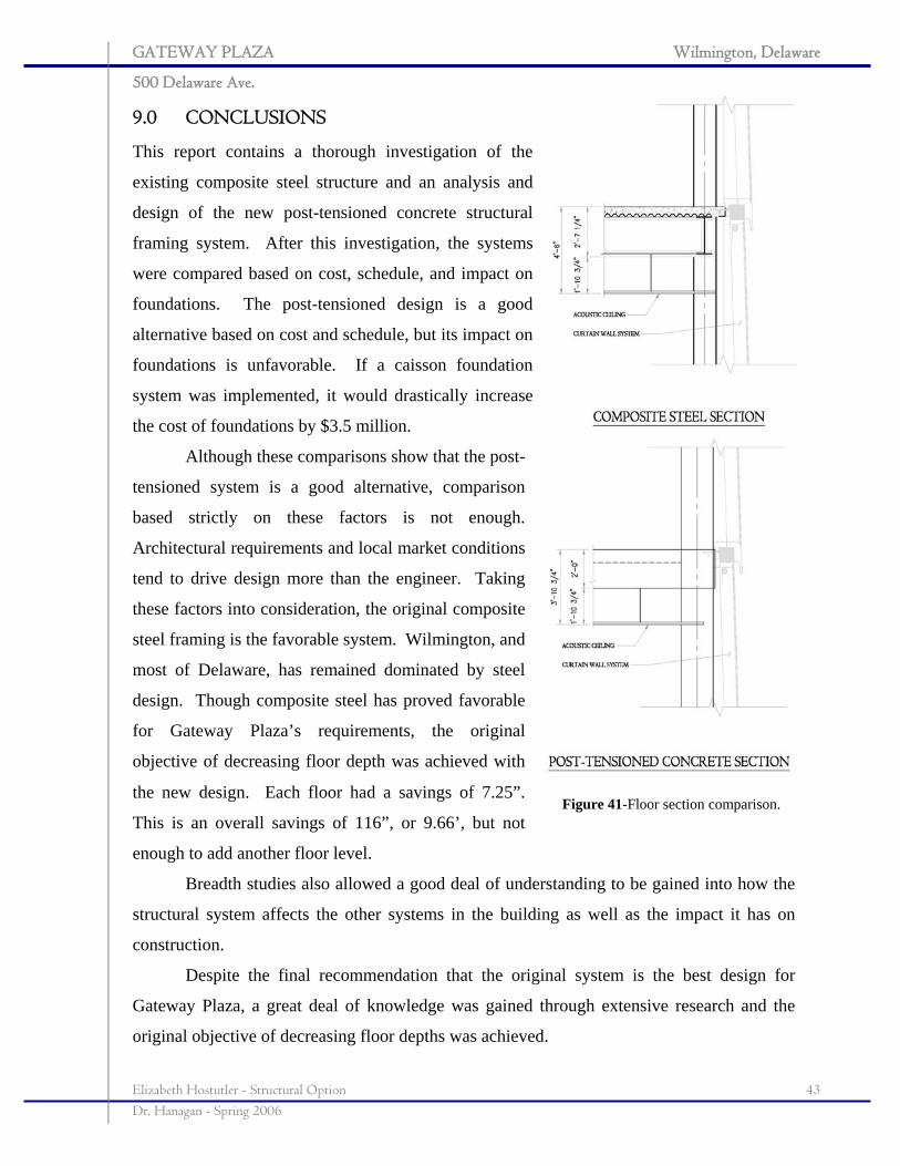
9.0 CONCLUSIONS
This report contains a thorough investigation of the
existing composite steel structure and an analysis and
design of the new post-tensioned concrete structural
framing system. After this investigation, the systems
were compared based on cost, schedule, and impact on
foundations. The post-tensioned design is a good
alternative based on cost and schedule, but its impact on
foundations is unfavorable. If a caisson foundation
system was implemented, it would drastically increase
the cost of foundations by $3.5 million.
Although these comparisons show that the post-
tensioned system is a good alternative, comparison
based strictly on these factors is not enough.
Architectural requirements and local market conditions
tend to drive design more than the engineer. Taking
these factors into consideration, the original composite
steel framing is the favorable system. Wilmington, and
most of Delaware, has remained dominated by steel
design. Though composite steel has proved favorable
for Gateway Plaza’s requirements, the original
objective of decreasing floor depth was achieved with
the new design. Each floor had a savings of 7.25”.
This is an overall savings of 116”, or 9.66’, but not
enough to add another floor level.
Breadth studies also allowed a good deal of understanding to be gained into how the
structural system affects the other systems in the building as well as the impact it has on
construction.
Despite the final recommendation that the original system is the best design for
Gateway Plaza, a great deal of knowledge was gained through extensive research and the
original objective of decreasing floor depths was achieved.
Figure 41-Floor section comparison.
GATEWAY PLAZA Wilmington, Delaware
500 Delaware Ave.
Elizabeth Hostutler - Structural Option 44 Dr. Hanagan - Spring 2006
CREDITS AND ACKNOWLEDGEMENTS
I would like express my sincere gratitude for helping along the way for this Senior Thesis
Project. This project could not have been executed so professionally without their time,
knowledge, and patience. Words cannot express my gratitude for how you have helped
shape me as an engineer. Thank you.
O’Donnell Naccarato & MacIntosh
Peter Paton, Structural Engineer
Gilbane
Craig Hedlund, Construction Manager
AE Advisors
Dr. Linda M. Hanagan
Dr. Thomas Boothby
Professor M. Kevin Parfitt
AE Students
David J. Melfi
Justin Mulhollan
Anthony Lucositic
Chad Illig
I would also like to thank my boyfriend, Steve, because we got through this project together.
Finally, I would like to thank my family: Jim, Kathy, Matt, Megan, and Mark Hostutler, Ann
and Joseph Barnes and Jessie Hostutler. Your support, encouragement, and inspiration have
helped me through the years in ways that words cannot express. I am blessed to have the
most wonderful support group and cheering section in the world. I love you.
GATEWAY PLAZA Wilmington, Delaware
500 Delaware Ave.
Elizabeth Hostutler - Structural Option 45 Dr. Hanagan - Spring 2006
REFERENCES
Structural
American Concrete Institute. Building Code Requirements for Structural Concrete (ACI
318-05) and Commentary (ACI 318R-05). Farmington Hills, MI: 2005.
Atlas Prestressing Corp. Post-tensioned Concrete Design Workbook: Prepared for a One
Day Symposium. Panorama City, CA: 1970.
Naaman, Antoine E. Prestressed Concrete Analysis and Design, Second edition. Techno
Press 3000. Ann Arbor, Michigan: 2004.
Nilson, Arthur H, et al. Design of Concrete Structures, 13th ed. McGraw Hill Higher
Education. New York, NY: 2004.
Portland Cement Association. Two-Way Post-tensioned design example.
http://www.cement.org/buildings/Timesaving-2WayPost-IA.pdf
Post-Tensioning Institute. Post-Tensioning Manual, Second edition. Glenview, Illinois: 1976.
Mechanical
ANSI/ASHRAE Standard 62.1-2004: Ventilation for Acceptable Indoor Air Quality.
American Society of Heating, Refrigerating and Air-Conditioning Engineers, Inc.
Atlanta, GA: 2004. p10-15.
McQuiston, Faye, et al. Heating, Ventilating, and Air Conditioning Analysis and Design, 5th
edition. John Wiley & Sons, Inc. New York, NY: 2000. p 362-89.
Construction
RSMeans Construction Cost Data: 2005.
Madsen, Jana J. Concrete v. Steel.
http://www.buildings.com/Articles/detail.asp?ArticleID=2511.
GATEWAY PLAZA Wilmington, Delaware
500 Delaware Ave.
Elizabeth Hostutler - Structural Option i Dr. Hanagan - Spring 2006
APPENDICES
GATEWAY PLAZA Wilmington, Delaware
500 Delaware Ave.
Elizabeth Hostutler - Structural Option ii Dr. Hanagan - Spring 2006
APPENDICES APPENDIX A: LOAD CALCULATIONS .......................................................................... iii
A.1 Snow Loading ..........................................................................................................iv
A.2 Lateral Loading .......................................................................................................vi
A.2.1 Wind ............................................................................................................................... vi
A.2.2 Seismic ............................................................................................................................ xi
APPENDIX B: PRELIMINARY MEMBER DESIGN.................................................... xiii
B.1 Post-tensioned Slab ..............................................................................................xiv
B.2 Columns ..................................................................................................................xvi
B.3 Beams .......................................................................................................................xix
B.4 Shearwalls................................................................................................................xxi
APPENDIX C: PLANS............................................................................................................ xxii
C.1 Composite Steel-Foundation........................................................................... xxiii
C.2 Composite Steel-Typical Floor........................................................................xxiv
C.3 Post-tensioned Concrete-Foundation..............................................................xxv
C.4 Post-tensioned Concrete-Floor Framing .......................................................xxvi
C.5 Post-tensioned Concrete-Reinforcement.................................................... xxviii
APPENDIX D: BREADTH STUDIES ............................................................................ xxxii
D.1 Mechanical Studies .......................................................................................... xxxiii
D.2 Construction Studies ........................................................................................xxxiv
D.2.1 Material Takeoffs ................................................................................................... xxxiv
D.2.2 Estimates.................................................................................................................... xxxv
D.2.3 Schedule...................................................................................................................xxxvii
GATEWAY PLAZA Wilmington, Delaware
500 Delaware Ave.
Elizabeth Hostutler - Structural Option iii Dr. Hanagan - Spring 2006
APPENDIX A: LOAD CALCULATIONS
GATEWAY PLAZA Wilmington, Delaware
500 Delaware Ave.
Elizabeth Hostutler - Structural Option iv Dr. Hanagan - Spring 2006
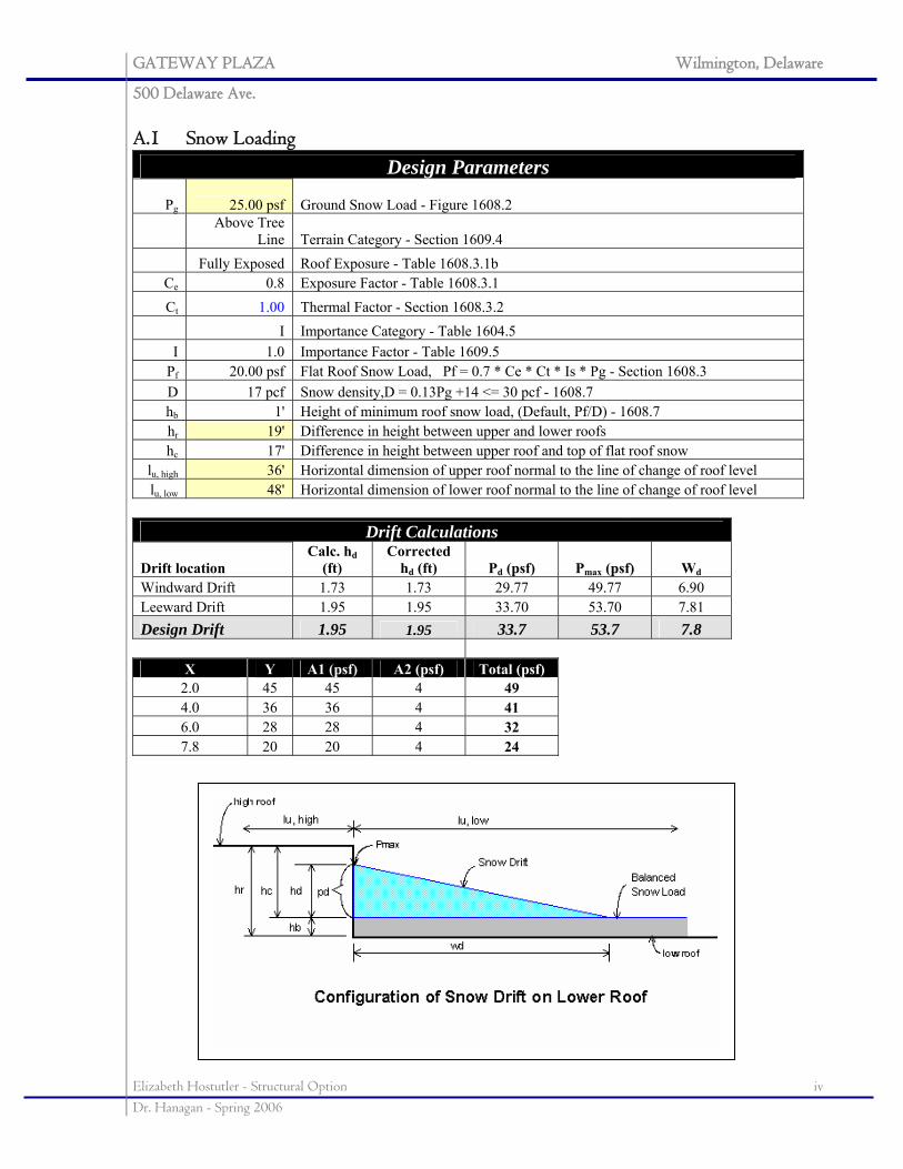
A.1 Snow Loading
Design Parameters
Pg 25.00 psf Ground Snow Load - Figure 1608.2
Above Tree
Line Terrain Category - Section 1609.4 Fully Exposed Roof Exposure - Table 1608.3.1b
Ce 0.8 Exposure Factor - Table 1608.3.1 Ct 1.00 Thermal Factor - Section 1608.3.2
I Importance Category - Table 1604.5 I 1.0 Importance Factor - Table 1609.5
Pf 20.00 psf Flat Roof Snow Load, Pf = 0.7 * Ce * Ct * Is * Pg - Section 1608.3 D 17 pcf Snow density,D = 0.13Pg +14 <= 30 pcf - 1608.7 hb 1' Height of minimum roof snow load, (Default, Pf/D) - 1608.7 hr 19' Difference in height between upper and lower roofs hc 17' Difference in height between upper roof and top of flat roof snow
lu, high 36' Horizontal dimension of upper roof normal to the line of change of roof level lu, low 48' Horizontal dimension of lower roof normal to the line of change of roof level
Drift Calculations
Drift location Calc. hd
(ft) Corrected
hd (ft) Pd (psf) Pmax (psf) Wd Windward Drift 1.73 1.73 29.77 49.77 6.90 Leeward Drift 1.95 1.95 33.70 53.70 7.81 Design Drift 1.95 1.95 33.7 53.7 7.8
X Y A1 (psf) A2 (psf) Total (psf) 2.0 45 45 4 49 4.0 36 36 4 41 6.0 28 28 4 32 7.8 20 20 4 24
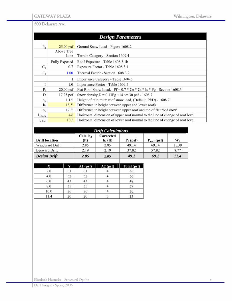
GATEWAY PLAZA Wilmington, Delaware
500 Delaware Ave.
Elizabeth Hostutler - Structural Option v Dr. Hanagan - Spring 2006
Design Parameters
Pg 25.00 psf Ground Snow Load - Figure 1608.2
Above Tree
Line Terrain Category - Section 1609.4 Fully Exposed Roof Exposure - Table 1608.3.1b
Ce 0.7 Exposure Factor - Table 1608.3.1 Ct 1.00 Thermal Factor - Section 1608.3.2
I Importance Category - Table 1604.5 I 1.0 Importance Factor - Table 1609.5
Pf 20.00 psf Flat Roof Snow Load, Pf = 0.7 * Ce * Ct * Is * Pg - Section 1608.3 D 17.25 pcf Snow density,D = 0.13Pg +14 <= 30 pcf - 1608.7 hb 1.16' Height of minimum roof snow load, (Default, Pf/D) - 1608.7 hr 18.5' Difference in height between upper and lower roofs hc 17.3' Difference in height between upper roof and top of flat roof snow
lu, high 44' Horizontal dimension of upper roof normal to the line of change of roof level lu, low 130' Horizontal dimension of lower roof normal to the line of change of roof level
Drift Calculations
Drift location Calc. hd
(ft) Corrected
hd (ft) Pd (psf) Pmax (psf) Wd Windward Drift 2.85 2.85 49.14 69.14 11.39 Leeward Drift 2.19 2.19 37.82 57.82 8.77 Design Drift 2.85 2.85 49.1 69.1 11.4
X Y A1 (psf) A2 (psf) Total (psf) 2.0 61 61 4 65 4.0 52 52 4 56 6.0 43 43 4 48 8.0 35 35 4 39
10.0 26 26 4 30 11.4 20 20 3 23
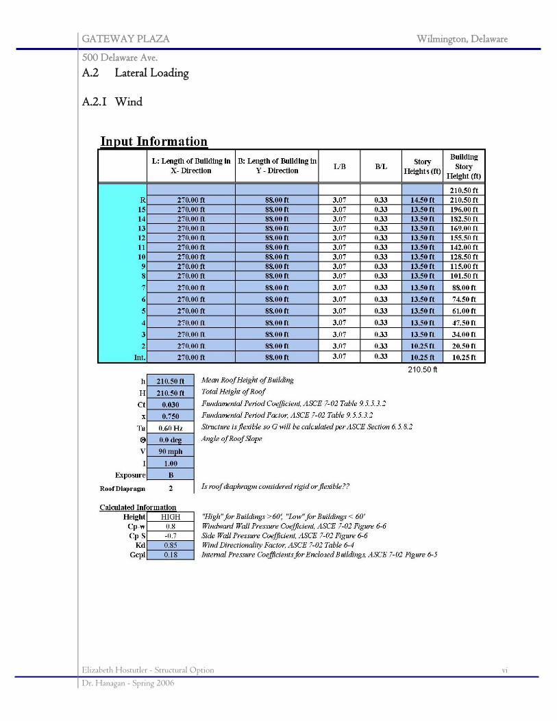
GATEWAY PLAZA Wilmington, Delaware
500 Delaware Ave.
Elizabeth Hostutler - Structural Option vi Dr. Hanagan - Spring 2006
A.2 Lateral Loading A.2.1 Wind
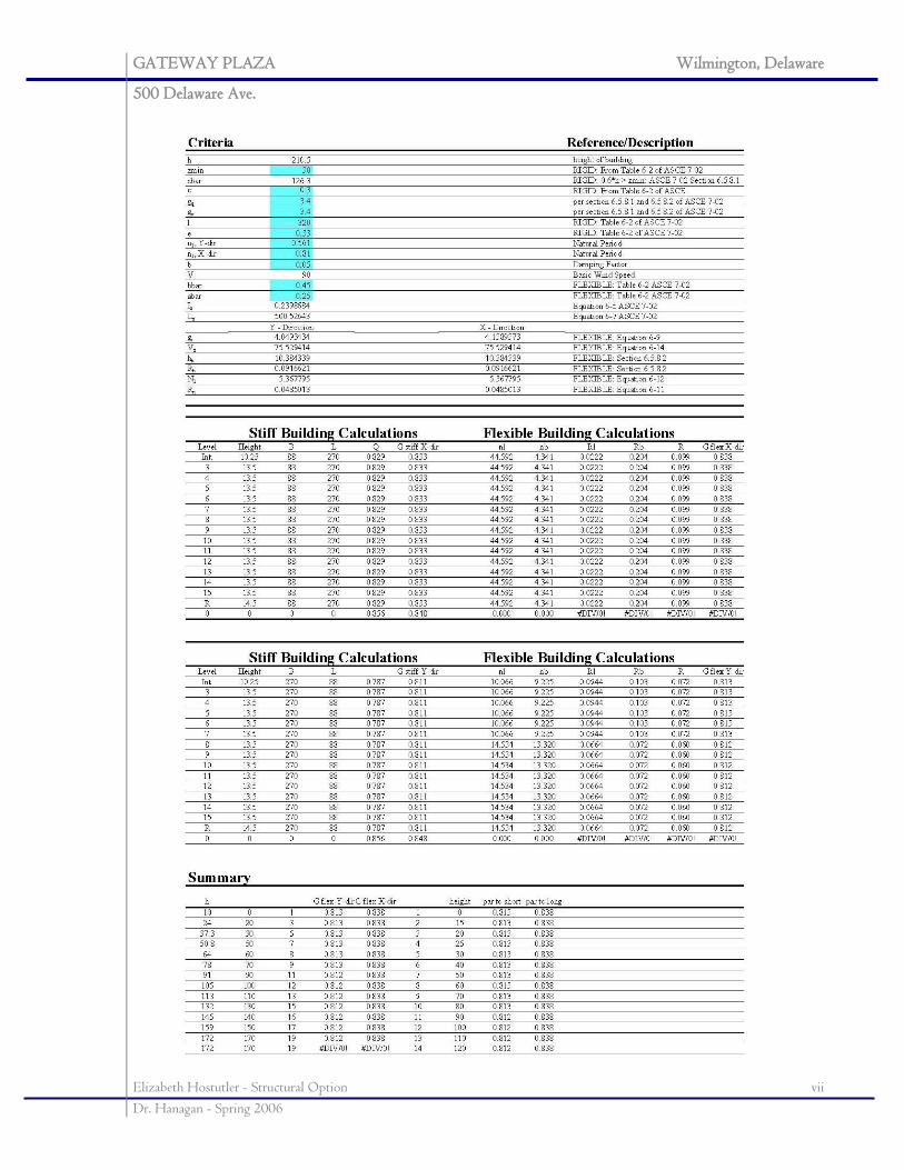
GATEWAY PLAZA Wilmington, Delaware
500 Delaware Ave.
Elizabeth Hostutler - Structural Option vii Dr. Hanagan - Spring 2006
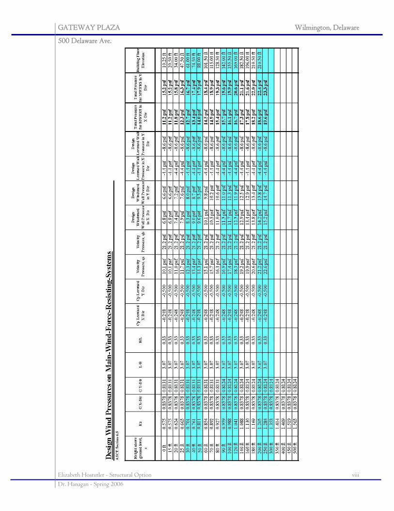
GATEWAY PLAZA Wilmington, Delaware
500 Delaware Ave.
Elizabeth Hostutler - Structural Option viii Dr. Hanagan - Spring 2006
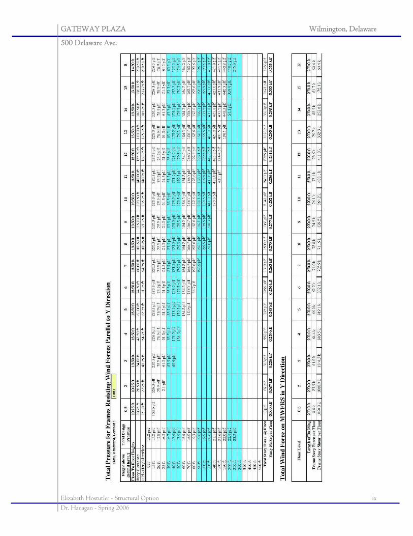
GATEWAY PLAZA Wilmington, Delaware
500 Delaware Ave.
Elizabeth Hostutler - Structural Option ix Dr. Hanagan - Spring 2006
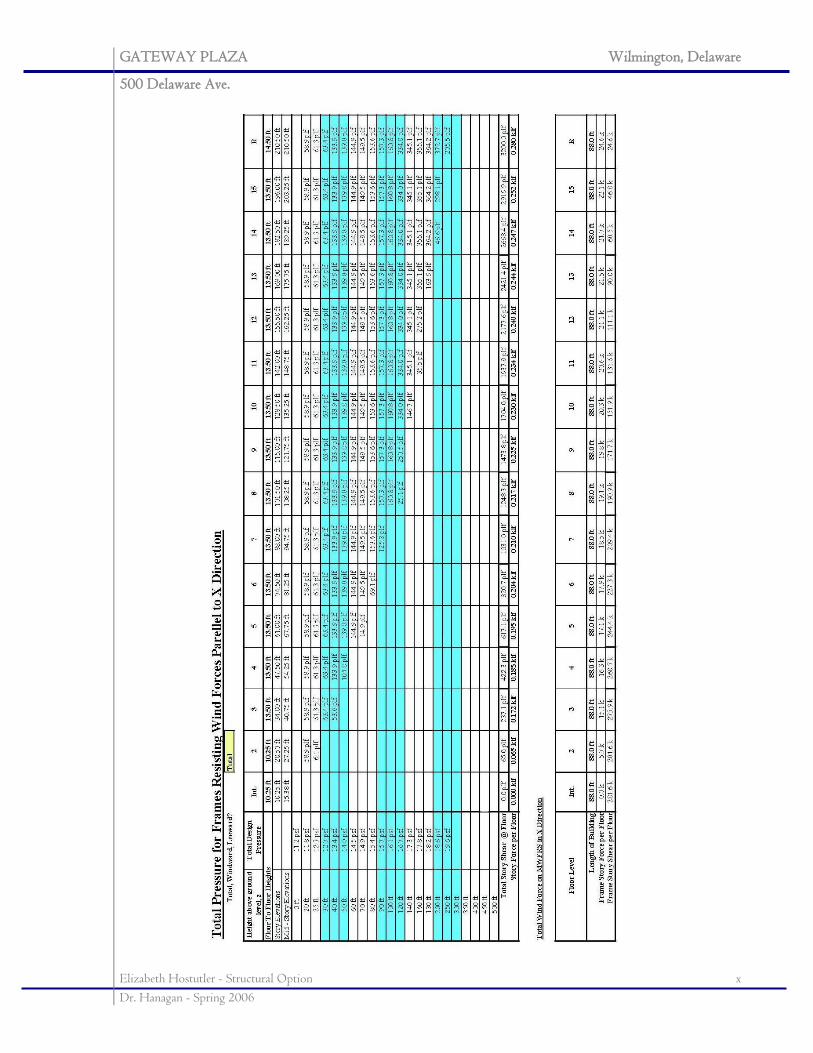
GATEWAY PLAZA Wilmington, Delaware
500 Delaware Ave.
Elizabeth Hostutler - Structural Option x Dr. Hanagan - Spring 2006
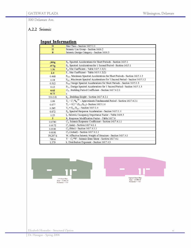
GATEWAY PLAZA Wilmington, Delaware
500 Delaware Ave.
Elizabeth Hostutler - Structural Option xi Dr. Hanagan - Spring 2006
A.2.2 Seismic
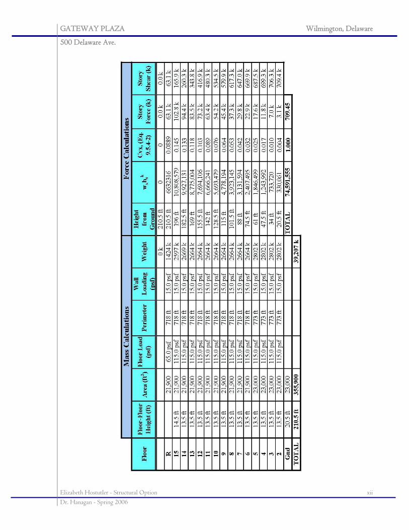
GATEWAY PLAZA Wilmington, Delaware
500 Delaware Ave.
Elizabeth Hostutler - Structural Option xii Dr. Hanagan - Spring 2006
GATEWAY PLAZA Wilmington, Delaware
500 Delaware Ave.
Elizabeth Hostutler - Structural Option xiii Dr. Hanagan - Spring 2006
APPENDIX B: PRELIMINARY MEMBER DESIGN
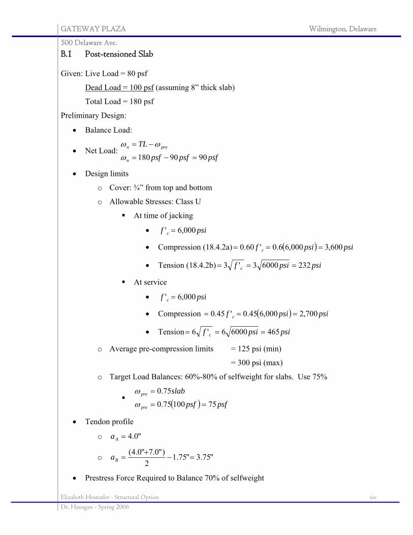
GATEWAY PLAZA Wilmington, Delaware
500 Delaware Ave.
Elizabeth Hostutler - Structural Option xiv Dr. Hanagan - Spring 2006
B.1 Post-tensioned Slab Given: Live Load = 80 psf
Dead Load = 100 psf (assuming 8” thick slab)
Total Load = 180 psf
Preliminary Design:
• Balance Load:
• Net Load: psfpsfpsf
TL
n
pren
9090180 =−=
−=
ω
ωω
• Design limits
o Cover: ¾” from top and bottom
o Allowable Stresses: Class U
At time of jacking
• psif c 000,6' =
• Compression (18.4.2a) ( ) psipsif c 600,3000,66.0'60.0 ===
• Tension (18.4.2b) psipsif c 23260003'3 ===
At service
• psif c 000,6' =
• Compression ( ) psipsif c 700,2000,645.0'45.0 ===
• Tension psipsif c 46560006'6 ===
o Average pre-compression limits = 125 psi (min)
= 300 psi (max)
o Target Load Balances: 60%-80% of selfweight for slabs. Use 75%
( ) psfpsf
slab
pre
pre
7510075.0
75.0
==
=
ω
ω
• Tendon profile
o "0.4=Aa
o "75.3"75.12
)"0.7"0.4(=−
+=Ba
• Prestress Force Required to Balance 70% of selfweight
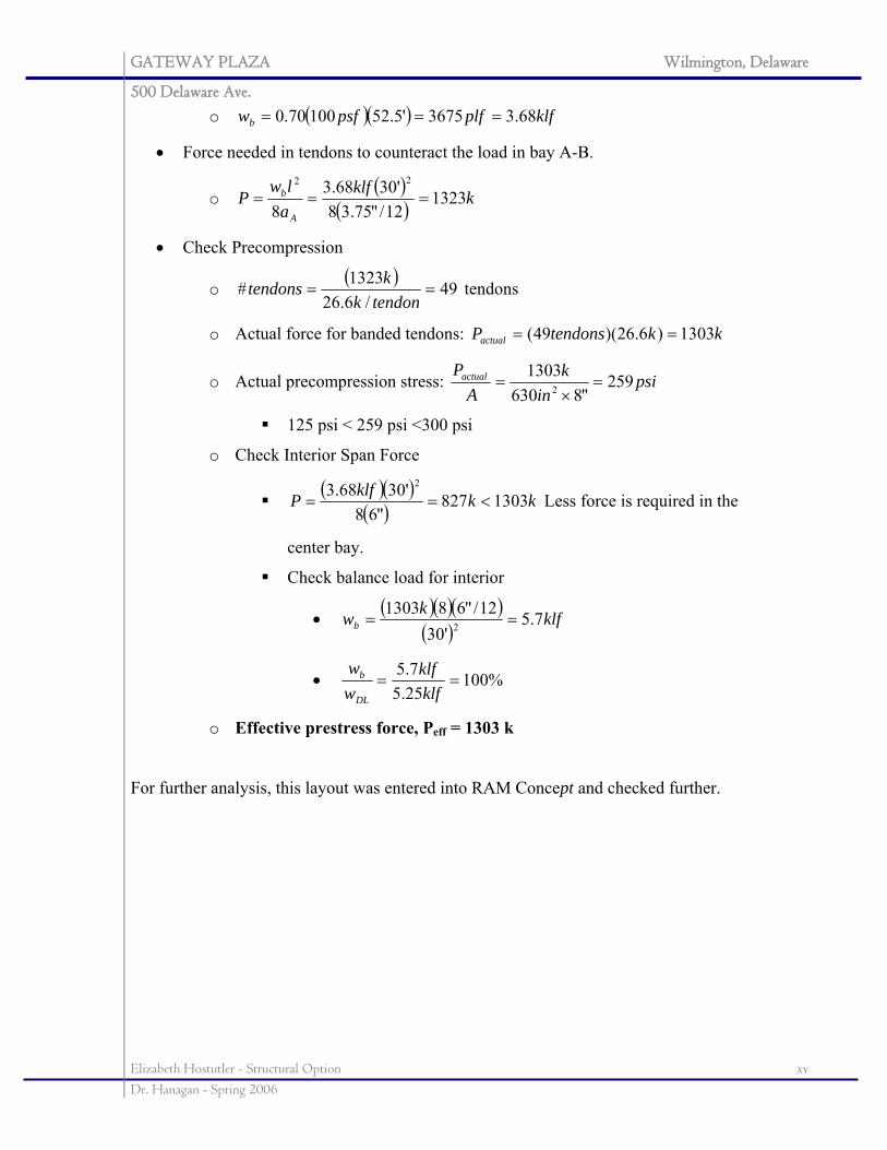
GATEWAY PLAZA Wilmington, Delaware
500 Delaware Ave.
Elizabeth Hostutler - Structural Option xv Dr. Hanagan - Spring 2006
o ( )( ) klfplfpsfwb 68.33675'5.5210070.0 ===
• Force needed in tendons to counteract the load in bay A-B.
o ( )( ) kklf
alw
PA
b 132312/"75.38
'3068.38
22
===
• Check Precompression
o ( ) 49/6.26
1323# ==tendonk
ktendons tendons
o Actual force for banded tendons: kktendonsPactual 1303)6.26)(49( ==
o Actual precompression stress: psiin
kA
Pactual 259"8630
13032 =×
=
125 psi < 259 psi <300 psi
o Check Interior Span Force
( )( )( ) kkklfP 1303827
"68'3068.3 2
<== Less force is required in the
center bay.
Check balance load for interior
• ( )( )( )( )
klfkwb 7.5'30
12/"6813032 ==
• %10025.57.5
==klfklf
ww
DL
b
o Effective prestress force, Peff = 1303 k
For further analysis, this layout was entered into RAM Concept and checked further.
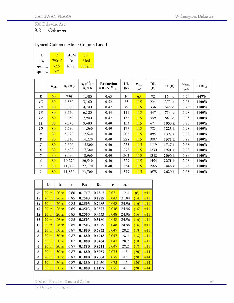
GATEWAY PLAZA Wilmington, Delaware
500 Delaware Ave.
Elizabeth Hostutler - Structural Option xvi Dr. Hanagan - Spring 2006
B.2 Columns
Typical Columns Along Column Line 1
k 2 trib. W 30' At 790 sf f'c 6 ksi
span lab 52.5' beam 800 plf span lbc 36'
wLL At (ft2) Ai (ft2) = At x k
Reduction = 0.25+15/√Ai
LL (k)
wDL
(psf) DL (k) Pu (k) wuTL
(psf) FEMab
R 60 790 1,580 0.63 30 65 72 134 k 3.24 447'k 15 80 1,580 3,160 0.52 65 115 224 373 k 7.98 1100'k 14 80 2,370 4,740 0.47 89 115 336 545 k 7.98 1100'k 13 80 3,160 6,320 0.44 111 115 447 714 k 7.98 1100'k 12 80 3,950 7,900 0.42 132 115 559 883 k 7.98 1100'k 11 80 4,740 9,480 0.40 153 115 671 1050 k 7.98 1100'k 10 80 5,530 11,060 0.40 177 115 783 1223 k 7.98 1100'k 9 80 6,320 12,640 0.40 202 115 895 1397 k 7.98 1100'k 8 80 7,110 14,220 0.40 228 115 1007 1572 k 7.98 1100'k 7 80 7,900 15,800 0.40 253 115 1119 1747 k 7.98 1100'k 6 80 8,690 17,380 0.40 278 115 1230 1921 k 7.98 1100'k 5 80 9,480 18,960 0.40 303 115 1342 2096 k 7.98 1100'k 4 80 10,270 20,540 0.40 329 115 1454 2271 k 7.98 1100'k 3 80 11,060 22,120 0.40 354 115 1566 2445 k 7.98 1100'k 2 80 11,850 23,700 0.40 379 115 1678 2620 k 7.98 1100'k
b h γ Rn Kn ρ As
R 20 in 20 in 0.80 0.1717 0.0862 0.031 12.4 (8) #1115 20 in 26 in 0.85 0.2503 0.1839 0.042 21.84 (14) #1114 20 in 26 in 0.85 0.2503 0.2685 0.048 24.96 (16) #1113 20 in 26 in 0.85 0.2503 0.3522 0.048 24.96 (16) #1112 20 in 26 in 0.85 0.2503 0.4353 0.048 24.96 (16) #1111 20 in 26 in 0.85 0.2503 0.5180 0.048 24.96 (16) #1110 20 in 26 in 0.85 0.2503 0.6029 0.048 24.96 (16) #119 20 in 30 in 0.87 0.1880 0.5972 0.047 28.2 (18) #118 20 in 30 in 0.87 0.1880 0.6718 0.047 28.2 (18) #117 20 in 30 in 0.87 0.1880 0.7464 0.047 28.2 (18) #116 20 in 30 in 0.87 0.1880 0.8211 0.047 28.2 (18) #115 20 in 30 in 0.87 0.1880 0.8957 0.075 45 (20) #144 20 in 30 in 0.87 0.1880 0.9704 0.075 45 (20) #143 20 in 30 in 0.87 0.1880 1.0450 0.075 45 (20) #142 20 in 30 in 0.87 0.1880 1.1197 0.075 45 (20) #14
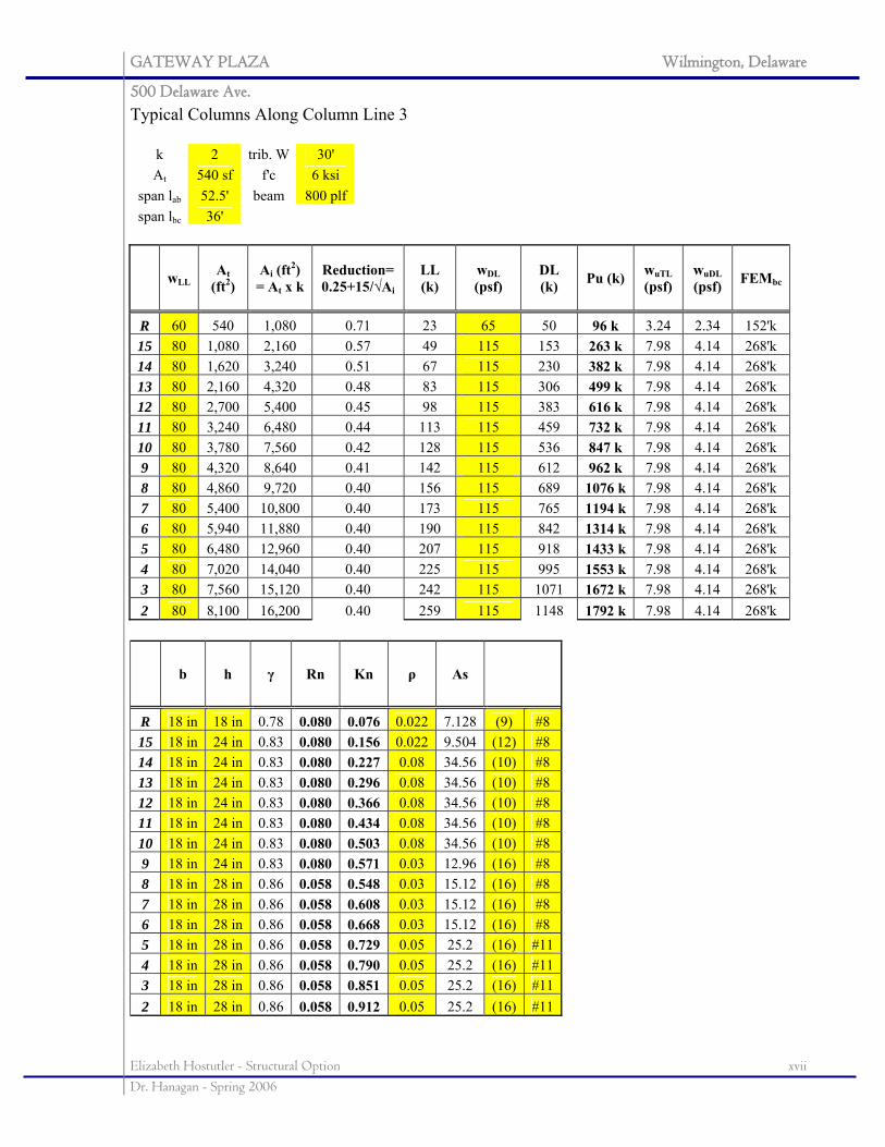
GATEWAY PLAZA Wilmington, Delaware
500 Delaware Ave.
Elizabeth Hostutler - Structural Option xvii Dr. Hanagan - Spring 2006
Typical Columns Along Column Line 3
k 2 trib. W 30' At 540 sf f'c 6 ksi
span lab 52.5' beam 800 plf span lbc 36'
wLL At (ft2)
Ai (ft2) = At x k
Reduction= 0.25+15/√Ai
LL (k)
wDL (psf)
DL (k) Pu (k) wuTL
(psf) wuDL (psf) FEMbc
R 60 540 1,080 0.71 23 65 50 96 k 3.24 2.34 152'k 15 80 1,080 2,160 0.57 49 115 153 263 k 7.98 4.14 268'k 14 80 1,620 3,240 0.51 67 115 230 382 k 7.98 4.14 268'k 13 80 2,160 4,320 0.48 83 115 306 499 k 7.98 4.14 268'k 12 80 2,700 5,400 0.45 98 115 383 616 k 7.98 4.14 268'k 11 80 3,240 6,480 0.44 113 115 459 732 k 7.98 4.14 268'k 10 80 3,780 7,560 0.42 128 115 536 847 k 7.98 4.14 268'k 9 80 4,320 8,640 0.41 142 115 612 962 k 7.98 4.14 268'k 8 80 4,860 9,720 0.40 156 115 689 1076 k 7.98 4.14 268'k 7 80 5,400 10,800 0.40 173 115 765 1194 k 7.98 4.14 268'k 6 80 5,940 11,880 0.40 190 115 842 1314 k 7.98 4.14 268'k 5 80 6,480 12,960 0.40 207 115 918 1433 k 7.98 4.14 268'k 4 80 7,020 14,040 0.40 225 115 995 1553 k 7.98 4.14 268'k 3 80 7,560 15,120 0.40 242 115 1071 1672 k 7.98 4.14 268'k 2 80 8,100 16,200 0.40 259 115 1148 1792 k 7.98 4.14 268'k
b h γ Rn Kn ρ As
R 18 in 18 in 0.78 0.080 0.076 0.022 7.128 (9) #8 15 18 in 24 in 0.83 0.080 0.156 0.022 9.504 (12) #8 14 18 in 24 in 0.83 0.080 0.227 0.08 34.56 (10) #8 13 18 in 24 in 0.83 0.080 0.296 0.08 34.56 (10) #8 12 18 in 24 in 0.83 0.080 0.366 0.08 34.56 (10) #8 11 18 in 24 in 0.83 0.080 0.434 0.08 34.56 (10) #8 10 18 in 24 in 0.83 0.080 0.503 0.08 34.56 (10) #8 9 18 in 24 in 0.83 0.080 0.571 0.03 12.96 (16) #8 8 18 in 28 in 0.86 0.058 0.548 0.03 15.12 (16) #8 7 18 in 28 in 0.86 0.058 0.608 0.03 15.12 (16) #8 6 18 in 28 in 0.86 0.058 0.668 0.03 15.12 (16) #8 5 18 in 28 in 0.86 0.058 0.729 0.05 25.2 (16) #114 18 in 28 in 0.86 0.058 0.790 0.05 25.2 (16) #113 18 in 28 in 0.86 0.058 0.851 0.05 25.2 (16) #112 18 in 28 in 0.86 0.058 0.912 0.05 25.2 (16) #11
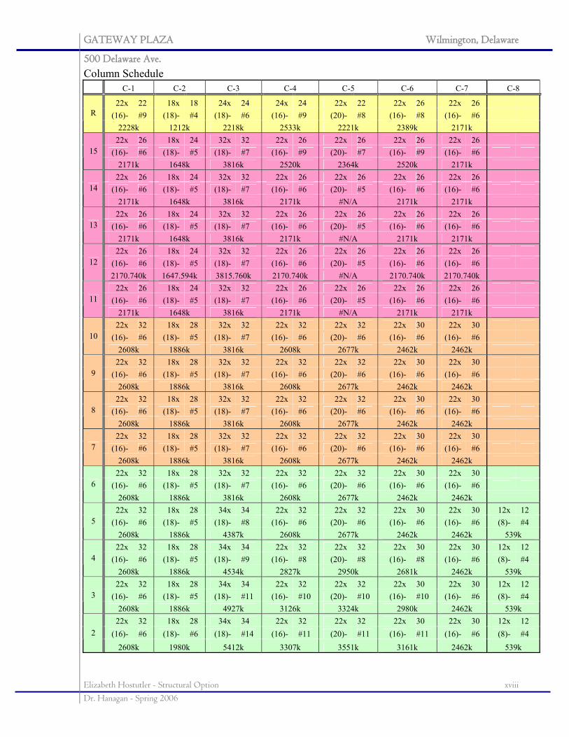
GATEWAY PLAZA Wilmington, Delaware
500 Delaware Ave.
Elizabeth Hostutler - Structural Option xviii Dr. Hanagan - Spring 2006
Column Schedule C-1 C-2 C-3 C-4 C-5 C-6 C-7 C-8
22x 22 18x 18 24x 24 24x 24 22x 22 22x 26 22x 26 (16)- #9 (18)- #4 (18)- #6 (16)- #9 (20)- #8 (16)- #8 (16)- #6 R
2228k 1212k 2218k 2533k 2221k 2389k 2171k 22x 26 18x 24 32x 32 22x 26 22x 26 22x 26 22x 26
(16)- #6 (18)- #5 (18)- #7 (16)- #9 (20)- #7 (16)- #9 (16)- #6 15 2171k 1648k 3816k 2520k 2364k 2520k 2171k
22x 26 18x 24 32x 32 22x 26 22x 26 22x 26 22x 26 (16)- #6 (18)- #5 (18)- #7 (16)- #6 (20)- #5 (16)- #6 (16)- #6 14
2171k 1648k 3816k 2171k #N/A 2171k 2171k 22x 26 18x 24 32x 32 22x 26 22x 26 22x 26 22x 26
(16)- #6 (18)- #5 (18)- #7 (16)- #6 (20)- #5 (16)- #6 (16)- #6 13 2171k 1648k 3816k 2171k #N/A 2171k 2171k
22x 26 18x 24 32x 32 22x 26 22x 26 22x 26 22x 26 (16)- #6 (18)- #5 (18)- #7 (16)- #6 (20)- #5 (16)- #6 (16)- #6 12 2170.740k 1647.594k 3815.760k 2170.740k #N/A 2170.740k 2170.740k
22x 26 18x 24 32x 32 22x 26 22x 26 22x 26 22x 26 (16)- #6 (18)- #5 (18)- #7 (16)- #6 (20)- #5 (16)- #6 (16)- #6 11
2171k 1648k 3816k 2171k #N/A 2171k 2171k 22x 32 18x 28 32x 32 22x 32 22x 32 22x 30 22x 30
(16)- #6 (18)- #5 (18)- #7 (16)- #6 (20)- #6 (16)- #6 (16)- #6 10 2608k 1886k 3816k 2608k 2677k 2462k 2462k
22x 32 18x 28 32x 32 22x 32 22x 32 22x 30 22x 30 (16)- #6 (18)- #5 (18)- #7 (16)- #6 (20)- #6 (16)- #6 (16)- #6 9
2608k 1886k 3816k 2608k 2677k 2462k 2462k 22x 32 18x 28 32x 32 22x 32 22x 32 22x 30 22x 30
(16)- #6 (18)- #5 (18)- #7 (16)- #6 (20)- #6 (16)- #6 (16)- #6 8 2608k 1886k 3816k 2608k 2677k 2462k 2462k
22x 32 18x 28 32x 32 22x 32 22x 32 22x 30 22x 30 (16)- #6 (18)- #5 (18)- #7 (16)- #6 (20)- #6 (16)- #6 (16)- #6 7
2608k 1886k 3816k 2608k 2677k 2462k 2462k 22x 32 18x 28 32x 32 22x 32 22x 32 22x 30 22x 30
(16)- #6 (18)- #5 (18)- #7 (16)- #6 (20)- #6 (16)- #6 (16)- #6 6 2608k 1886k 3816k 2608k 2677k 2462k 2462k
22x 32 18x 28 34x 34 22x 32 22x 32 22x 30 22x 30 12x 12 (16)- #6 (18)- #5 (18)- #8 (16)- #6 (20)- #6 (16)- #6 (16)- #6 (8)- #4 5
2608k 1886k 4387k 2608k 2677k 2462k 2462k 539k 22x 32 18x 28 34x 34 22x 32 22x 32 22x 30 22x 30 12x 12
(16)- #6 (18)- #5 (18)- #9 (16)- #8 (20)- #8 (16)- #8 (16)- #6 (8)- #4 4 2608k 1886k 4534k 2827k 2950k 2681k 2462k 539k
22x 32 18x 28 34x 34 22x 32 22x 32 22x 30 22x 30 12x 12 (16)- #6 (18)- #5 (18)- #11 (16)- #10 (20)- #10 (16)- #10 (16)- #6 (8)- #4 3
2608k 1886k 4927k 3126k 3324k 2980k 2462k 539k 22x 32 18x 28 34x 34 22x 32 22x 32 22x 30 22x 30 12x 12
(16)- #6 (18)- #6 (18)- #14 (16)- #11 (20)- #11 (16)- #11 (16)- #6 (8)- #4 2
2608k 1980k 5412k 3307k 3551k 3161k 2462k 539k
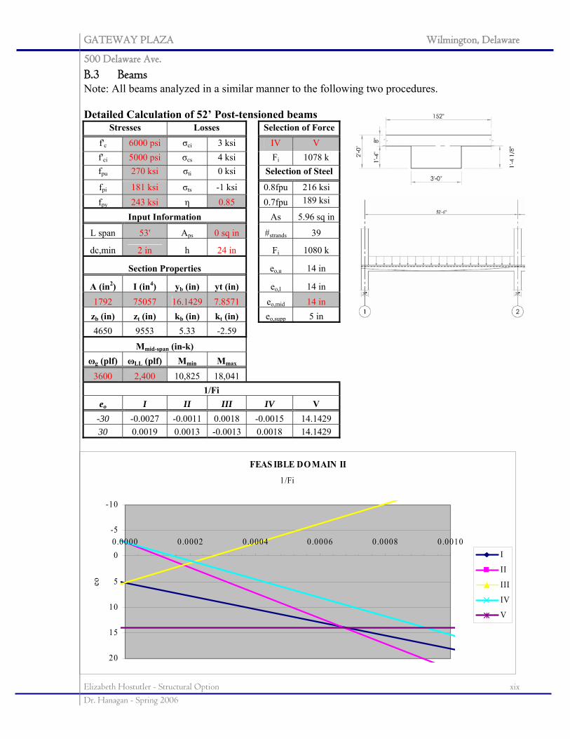
GATEWAY PLAZA Wilmington, Delaware
500 Delaware Ave.
Elizabeth Hostutler - Structural Option xix Dr. Hanagan - Spring 2006
FEAS IBLE DOMAIN II
-10
-5
0
5
10
15
20
0.0000 0.0002 0.0004 0.0006 0.0008 0.0010
1/Fi
eo
I
II
III
IV
V
B.3 Beams Note: All beams analyzed in a similar manner to the following two procedures. Detailed Calculation of 52’ Post-tensioned beams
Stresses Losses Selection of Forcef'c 6000 psi σci 3 ksi IV V f'ci 5000 psi σcs 4 ksi Fi 1078 k fpu 270 ksi σti 0 ksi Selection of Steel
fpi 181 ksi σts -1 ksi 0.8fpu 216 ksi fpy 243 ksi η 0.85 0.7fpu 189 ksi
Input Information As 5.96 sq in
L span 53' Aps 0 sq in #strands 39
dc,min 2 in h 24 in Fi 1080 k
Section Properties eo,u 14 in
A (in2) I (in4) yb (in) yt (in) eo,l 14 in 1792 75057 16.1429 7.8571 eo,mid 14 in
zb (in) zt (in) kb (in) kt (in) eo,supp 5 in 4650 9553 5.33 -2.59
Mmid-span (in-k) ωg (plf) ωLL (plf) Mmin Mmax
3600 2,400 10,825 18,041 1/Fi
eo I II III IV V -30 -0.0027 -0.0011 0.0018 -0.0015 14.1429 30 0.0019 0.0013 -0.0013 0.0018 14.1429
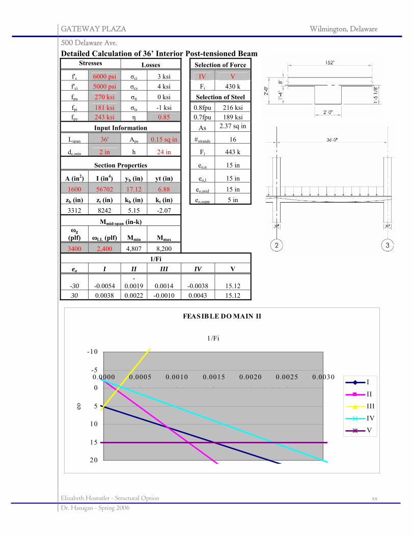
GATEWAY PLAZA Wilmington, Delaware
500 Delaware Ave.
Elizabeth Hostutler - Structural Option xx Dr. Hanagan - Spring 2006
FEAS IBLE DO MAIN II
-10
-5
0
5
10
15
20
0.0000 0.0005 0.0010 0.0015 0.0020 0.0025 0.0030
1/Fi
eo
I
II
III
IV
V
Detailed Calculation of 36’ Interior Post-tensioned Beam Stresses Losses Selection of Force
f'c 6000 psi σci 3 ksi IV V f'ci 5000 psi σcs 4 ksi Fi 430 k fpu 270 ksi σti 0 ksi Selection of Steel fpi 181 ksi σts -1 ksi 0.8fpu 216 ksi fpy 243 ksi η 0.85 0.7fpu 189 ksi
Input Information As 2.37 sq in
Lspan 36' Aps 0.15 sq in #strands 16
dc,min 2 in h 24 in Fi 443 k
Section Properties eo,u 15 in
A (in2) I (in4) yb (in) yt (in) eo,l 15 in 1600 56702 17.12 6.88 eo,mid 15 in
zb (in) zt (in) kb (in) kt (in) eo,supp 5 in 3312 8242 5.15 -2.07
Mmid-span (in-k) ωg
(plf) ωLL (plf) Mmin Mmax
3400 2,400 4,807 8,200 1/Fi
eo I II III IV V
-30 -0.0054 -
0.0019 0.0014 -0.0038 15.12 30 0.0038 0.0022 -0.0010 0.0043 15.12
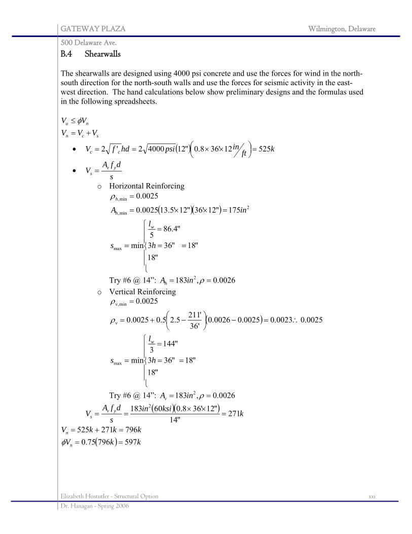
GATEWAY PLAZA Wilmington, Delaware
500 Delaware Ave.
Elizabeth Hostutler - Structural Option xxi Dr. Hanagan - Spring 2006
B.4 Shearwalls The shearwalls are designed using 4000 psi concrete and use the forces for wind in the north-south direction for the north-south walls and use the forces for seismic activity in the east-west direction. The hand calculations below show preliminary designs and the formulas used in the following spreadsheets.
scn
nu
VVVVV+=
≤ φ
• ( ) kftinpsihdfV cc 52512'368.0"1240002'2 =⎟
⎠⎞⎜
⎝⎛ ××==
• s
dfAV yv
s =
o Horizontal Reinforcing
( )( )
"18"18
"363
"4.865
min
175"12'36"12'5.130025.0
0025.0
max
2min,
min,
=
⎪⎪
⎩
⎪⎪
⎨
⎧
=
=
=
=××=
=
h
l
s
inA
w
h
hρ
Try #6 @ 14”: 0026.0,183 2 == ρinAh o Vertical Reinforcing
( )
"18"18
"363
"1443
min
0025.00023.00025.00026.0'36'2115.25.00025.0
0025.0
max
min,
=
⎪⎪
⎩
⎪⎪
⎨
⎧
=
=
=
∴=−⎟⎠⎞
⎜⎝⎛ −+=
=
h
l
s
w
v
v
ρ
ρ
Try #6 @ 14”: 0026.0,183 2 == ρinAv ( )( ) kksiin
sdfA
V yvs 271
"14"12'368.060183 2
=××
==
( ) kkVkkkV
n
n
59779675.0796271525
===+=
φ
GATEWAY PLAZA Wilmington, Delaware
500 Delaware Ave.
Elizabeth Hostutler - Structural Option xxii Dr. Hanagan - Spring 2006
APPENDIX C: PLANS
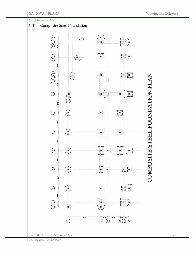
GATEWAY PLAZA Wilmington, Delaware
500 Delaware Ave.
Elizabeth Hostutler - Structural Option xxiii Dr. Hanagan - Spring 2006
C.1 Composite Steel-Foundation
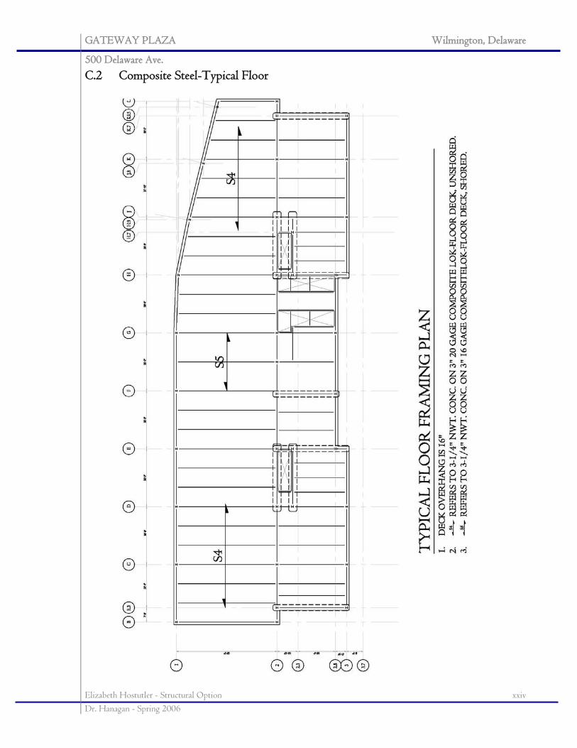
GATEWAY PLAZA Wilmington, Delaware
500 Delaware Ave.
Elizabeth Hostutler - Structural Option xxiv Dr. Hanagan - Spring 2006
C.2 Composite Steel-Typical Floor
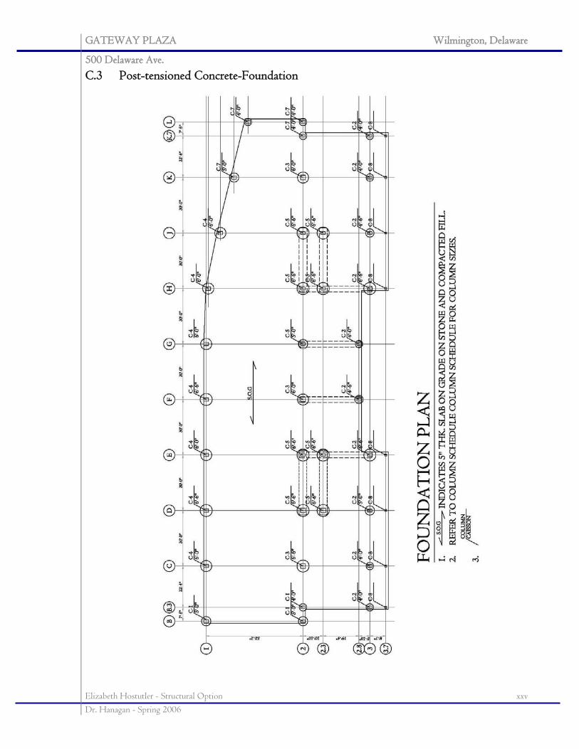
GATEWAY PLAZA Wilmington, Delaware
500 Delaware Ave.
Elizabeth Hostutler - Structural Option xxv Dr. Hanagan - Spring 2006
C.3 Post-tensioned Concrete-Foundation
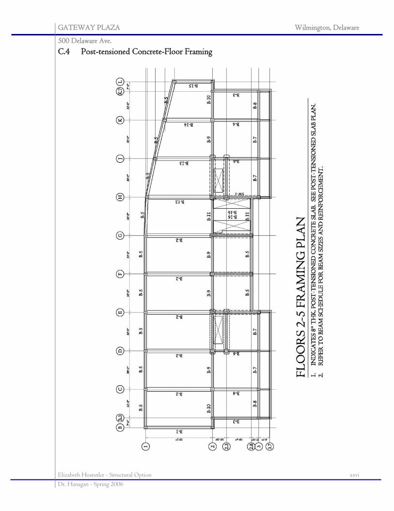
GATEWAY PLAZA Wilmington, Delaware
500 Delaware Ave.
Elizabeth Hostutler - Structural Option xxvi Dr. Hanagan - Spring 2006
C.4 Post-tensioned Concrete-Floor Framing
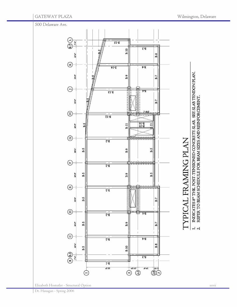
GATEWAY PLAZA Wilmington, Delaware
500 Delaware Ave.
Elizabeth Hostutler - Structural Option xxvii Dr. Hanagan - Spring 2006
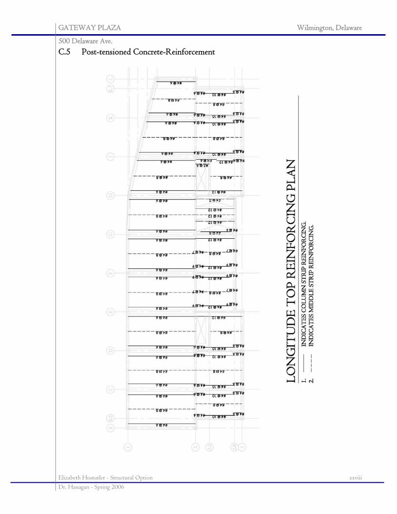
GATEWAY PLAZA Wilmington, Delaware
500 Delaware Ave.
Elizabeth Hostutler - Structural Option xxviii Dr. Hanagan - Spring 2006
C.5 Post-tensioned Concrete-Reinforcement
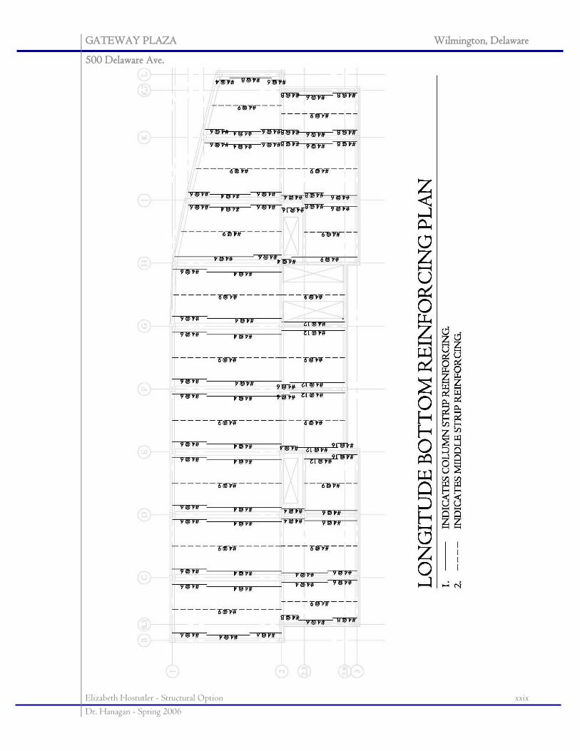
GATEWAY PLAZA Wilmington, Delaware
500 Delaware Ave.
Elizabeth Hostutler - Structural Option xxix Dr. Hanagan - Spring 2006
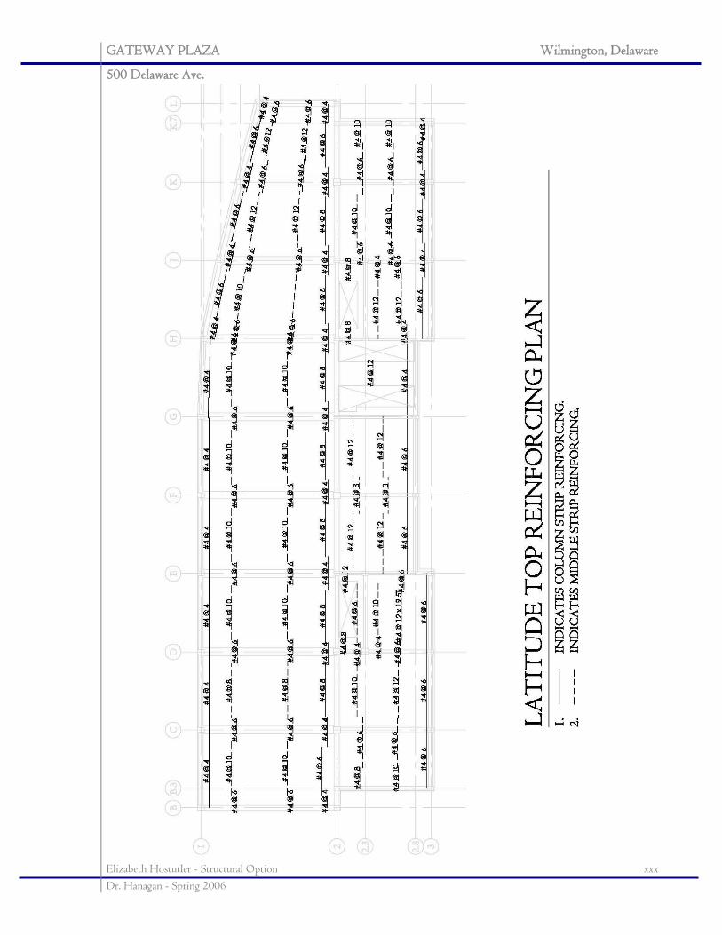
GATEWAY PLAZA Wilmington, Delaware
500 Delaware Ave.
Elizabeth Hostutler - Structural Option xxx Dr. Hanagan - Spring 2006
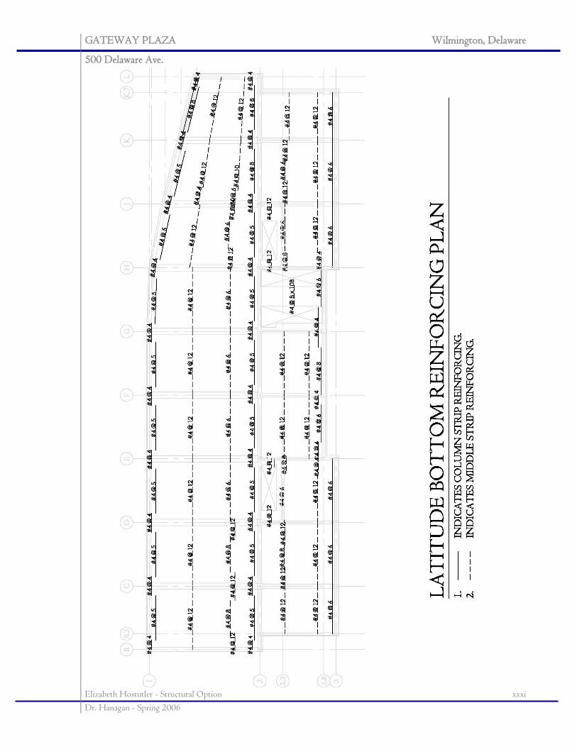
GATEWAY PLAZA Wilmington, Delaware
500 Delaware Ave.
Elizabeth Hostutler - Structural Option xxxi Dr. Hanagan - Spring 2006
GATEWAY PLAZA Wilmington, Delaware
500 Delaware Ave.
Elizabeth Hostutler - Structural Option xxxii Dr. Hanagan - Spring 2006
APPENDIX D: BREADTH STUDIES
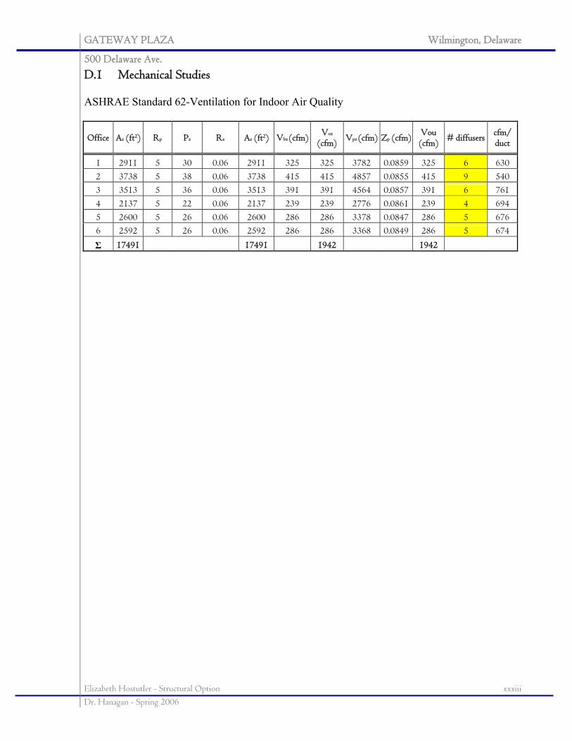
GATEWAY PLAZA Wilmington, Delaware
500 Delaware Ave.
Elizabeth Hostutler - Structural Option xxxiii Dr. Hanagan - Spring 2006
D.1 Mechanical Studies ASHRAE Standard 62-Ventilation for Indoor Air Quality
Office Az (ft2) Rp Pz Ra Az (ft2) Vbz (cfm) Voz
(cfm) Vpz (cfm) Zp (cfm) Vou (cfm) # diffusers cfm/
duct
1 2911 5 30 0.06 2911 325 325 3782 0.0859 325 6 630 2 3738 5 38 0.06 3738 415 415 4857 0.0855 415 9 540 3 3513 5 36 0.06 3513 391 391 4564 0.0857 391 6 761 4 2137 5 22 0.06 2137 239 239 2776 0.0861 239 4 694 5 2600 5 26 0.06 2600 286 286 3378 0.0847 286 5 676 6 2592 5 26 0.06 2592 286 286 3368 0.0849 286 5 674
Σ 17491 17491 1942 1942
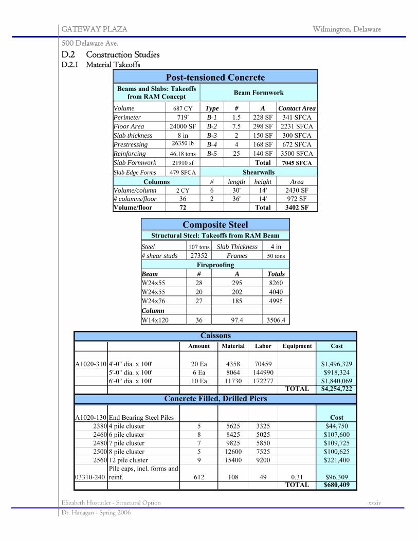
GATEWAY PLAZA Wilmington, Delaware
500 Delaware Ave.
Elizabeth Hostutler - Structural Option xxxiv Dr. Hanagan - Spring 2006
D.2 Construction Studies D.2.1 Material Takeoffs
Post-tensioned Concrete Beams and Slabs: Takeoffs
from RAM Concept Beam Formwork
Volume 687 CY Type # A Contact Area Perimeter 719' B-1 1.5 228 SF 341 SFCA Floor Area 24000 SF B-2 7.5 298 SF 2231 SFCA Slab thickness 8 in B-3 2 150 SF 300 SFCA Prestressing 26350 lb B-4 4 168 SF 672 SFCA Reinforcing 46.18 tons B-5 25 140 SF 3500 SFCA Slab Formwork 21910 sf Total 7045 SFCA Slab Edge Forms 479 SFCA Shearwalls
Columns # length height Area Volume/column 2 CY 6 30' 14' 2430 SF # columns/floor 36 2 36' 14' 972 SF Volume/floor 72 Total 3402 SF
Composite Steel
Structural Steel: Takeoffs from RAM Beam Steel 107 tons Slab Thickness 4 in # shear studs 27352 Frames 50 tons
Fireproofing Beam # A Totals W24x55 28 295 8260 W24x55 20 202 4040 W24x76 27 185 4995 Column W14x120 36 97.4 3506.4
Amount Material Labor Equipment Cost
A1020-310 4'-0" dia. x 100' 20 Ea 4358 70459 $1,496,3295'-0" dia. x 100' 6 Ea 8064 144990 $918,3246'-0" dia. x 100' 10 Ea 11730 172277 $1,840,069
TOTAL $4,254,722
A1020-130 End Bearing Steel Piles Cost2380 4 pile cluster 5 5625 3325 $44,7502460 6 pile cluster 8 8425 5025 $107,6002480 7 pile cluster 7 9825 5850 $109,7252500 8 pile cluster 5 12600 7525 $100,6252560 12 pile cluster 9 15400 9200 $221,400
03310-240Pile caps, incl. forms and reinf. 612 108 49 0.31 $96,309
TOTAL $680,409
Caissons
Concrete Filled, Drilled Piers
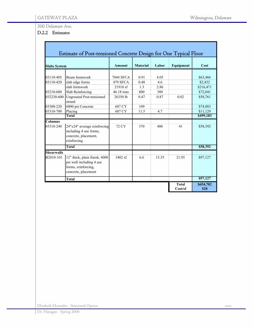
GATEWAY PLAZA Wilmington, Delaware
500 Delaware Ave.
Elizabeth Hostutler - Structural Option xxxv Dr. Hanagan - Spring 2006
D.2.2 Estimates
Amount Material Labor Equipment Cost
03110-405 Beam formwork 7044 SFCA 0.91 4.05 $63,46603110-420 slab edge forms 479 SFCA 0.48 4.6 $2,432
slab formwork 21910 sf 1.3 2.86 $216,47103210-600 Slab Reinforcing 46.18 tons 800 380 $72,041032230-600 Ungrouted Post-tensioned
strand26350 lb 0.47 0.87 0.02 $58,761
03300-220 6000 psi Concrete 687 CY 109 $74,88303310-700 Placing 687 CY 11.5 4.7 $11,129
Total $499,183
03310-240 24"x24" average reinforcing including 4 use forms, concrete, placement, reinforcing
72 CY 370 400 41 $58,392
Total $58,392
B2010-101 12" thick, plain finish, 4000 psi wall including 4 use forms, reinforcing, concrete, placement
3402 sf 6.6 15.35 21.95 $97,127
Total $97,127Total $654,702
Cost/sf $28
Estimate of Post-tensioned Concrete Design for One Typical Floor
Slabs System
Columns
Shearwalls
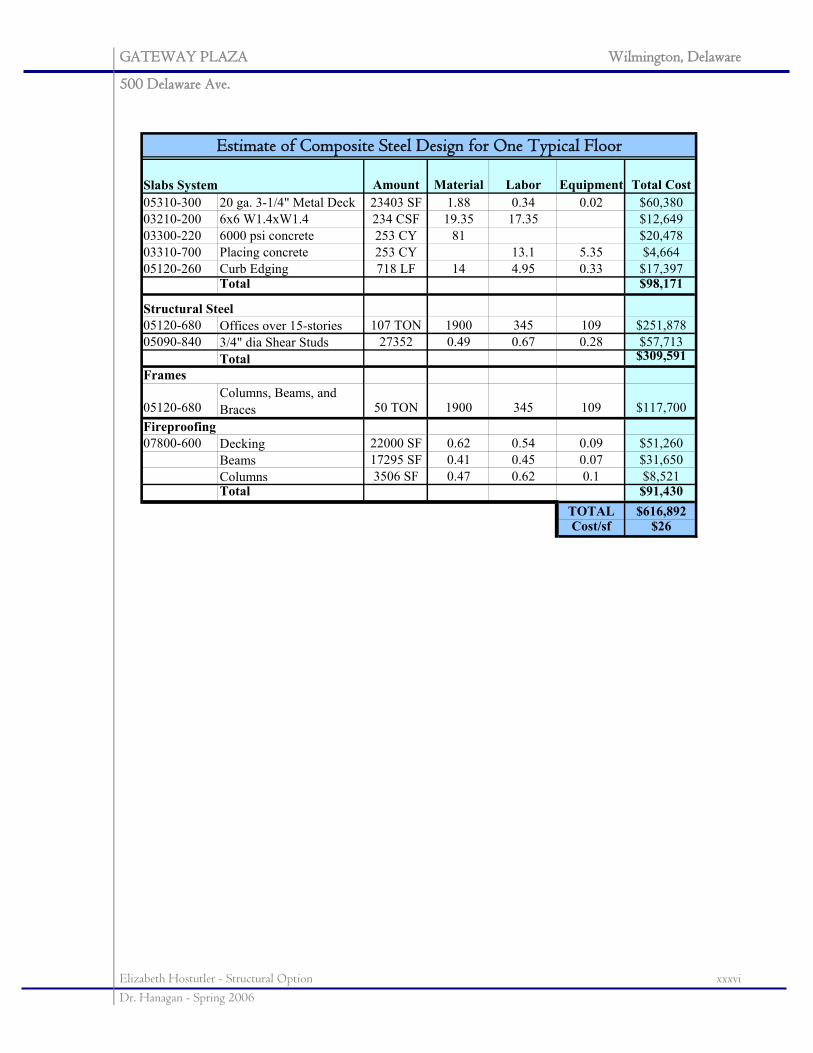
GATEWAY PLAZA Wilmington, Delaware
500 Delaware Ave.
Elizabeth Hostutler - Structural Option xxxvi Dr. Hanagan - Spring 2006
Amount Material Labor Equipment Total Cost05310-300 20 ga. 3-1/4" Metal Deck 23403 SF 1.88 0.34 0.02 $60,38003210-200 6x6 W1.4xW1.4 234 CSF 19.35 17.35 $12,64903300-220 6000 psi concrete 253 CY 81 $20,47803310-700 Placing concrete 253 CY 13.1 5.35 $4,66405120-260 Curb Edging 718 LF 14 4.95 0.33 $17,397
Total $98,171
05120-680 Offices over 15-stories 107 TON 1900 345 109 $251,87805090-840 3/4" dia Shear Studs 27352 0.49 0.67 0.28 $57,713
Total $309,591
05120-680Columns, Beams, and Braces 50 TON 1900 345 109 $117,700
07800-600 Decking 22000 SF 0.62 0.54 0.09 $51,260Beams 17295 SF 0.41 0.45 0.07 $31,650Columns 3506 SF 0.47 0.62 0.1 $8,521Total $91,430
TOTAL $616,892Cost/sf $26
Frames
Fireproofing
Estimate of Composite Steel Design for One Typical Floor
Slabs System
Structural Steel
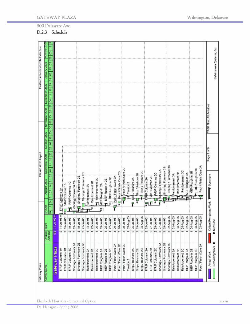
GATEWAY PLAZA Wilmington, Delaware
500 Delaware Ave.
Elizabeth Hostutler - Structural Option xxxvii Dr. Hanagan - Spring 2006
D.2.3 Schedule
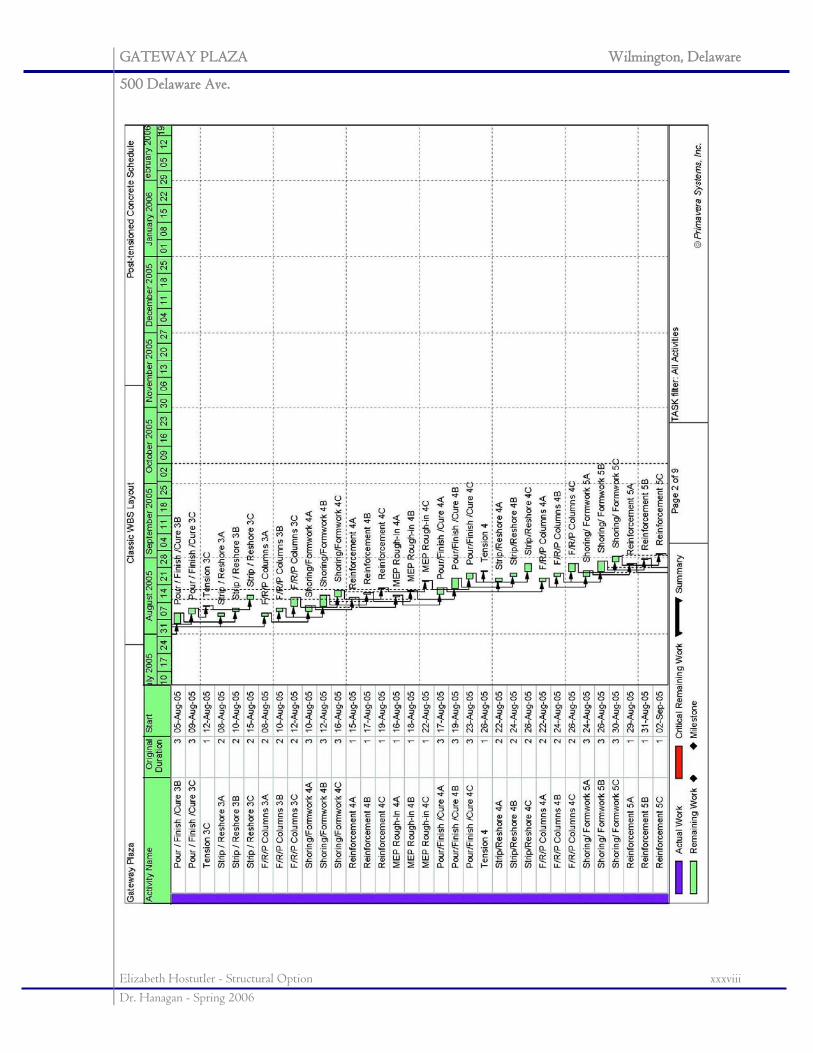
GATEWAY PLAZA Wilmington, Delaware
500 Delaware Ave.
Elizabeth Hostutler - Structural Option xxxviii Dr. Hanagan - Spring 2006
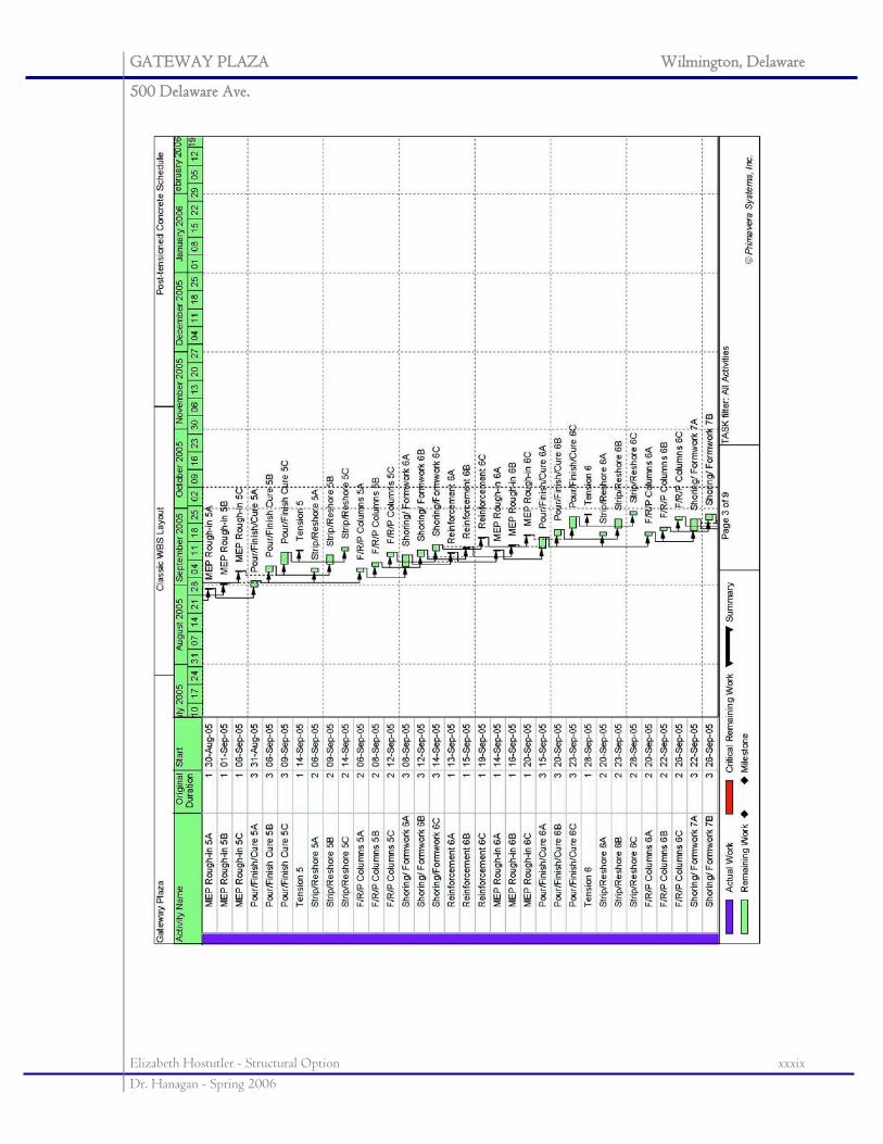
GATEWAY PLAZA Wilmington, Delaware
500 Delaware Ave.
Elizabeth Hostutler - Structural Option xxxix Dr. Hanagan - Spring 2006
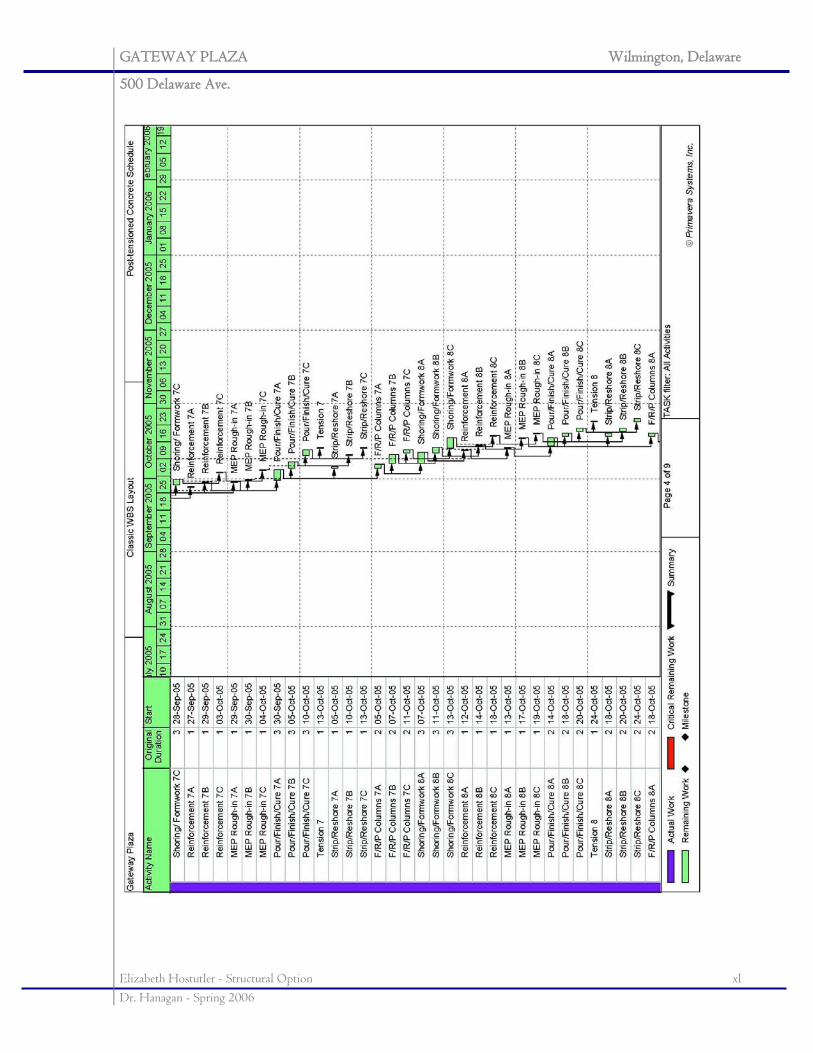
GATEWAY PLAZA Wilmington, Delaware
500 Delaware Ave.
Elizabeth Hostutler - Structural Option xl Dr. Hanagan - Spring 2006
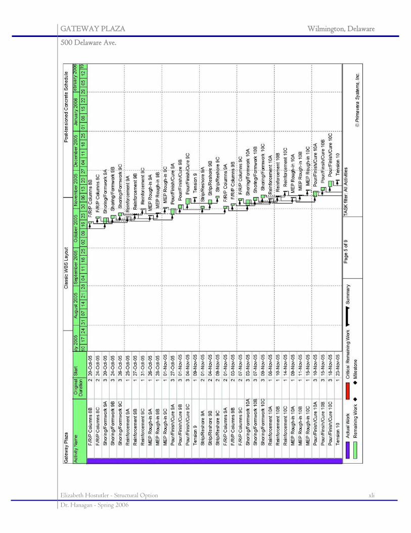
GATEWAY PLAZA Wilmington, Delaware
500 Delaware Ave.
Elizabeth Hostutler - Structural Option xli Dr. Hanagan - Spring 2006
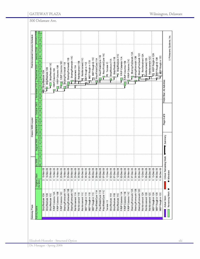
GATEWAY PLAZA Wilmington, Delaware
500 Delaware Ave.
Elizabeth Hostutler - Structural Option xlii Dr. Hanagan - Spring 2006
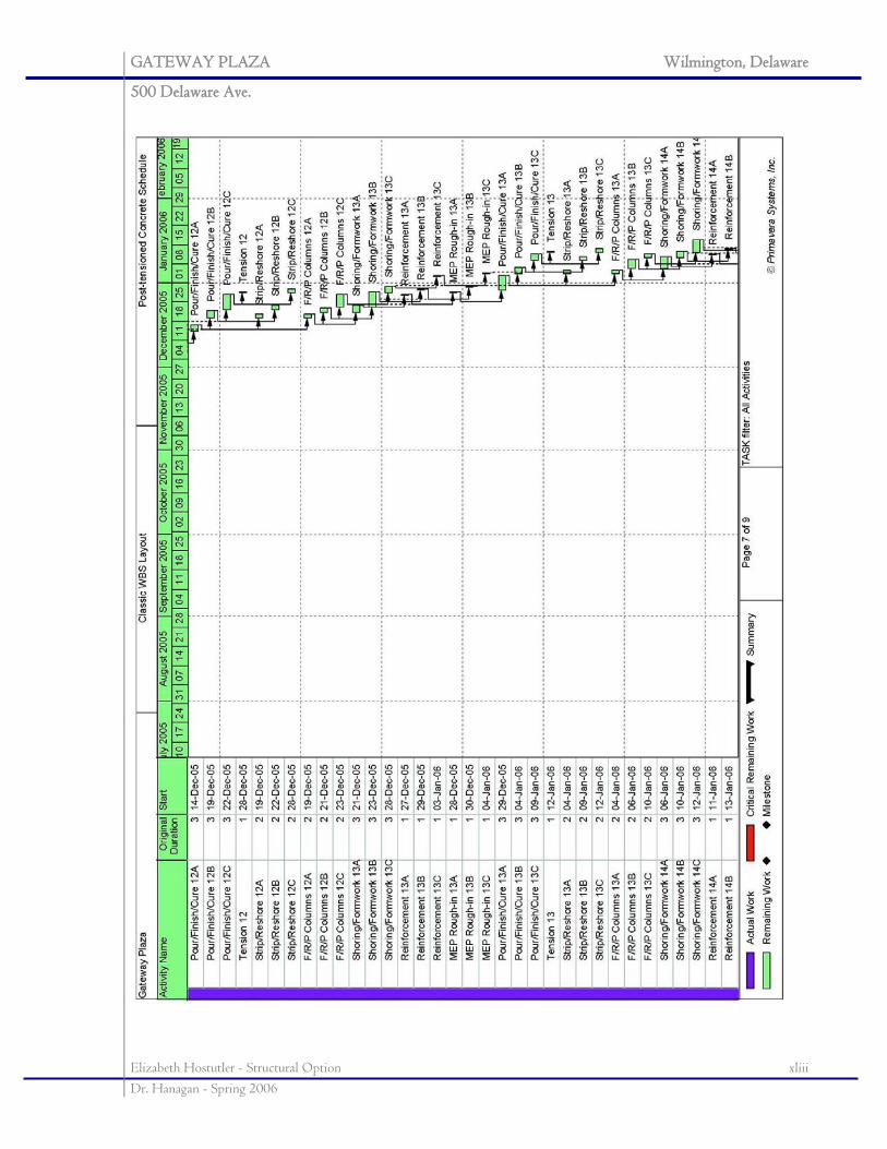
GATEWAY PLAZA Wilmington, Delaware
500 Delaware Ave.
Elizabeth Hostutler - Structural Option xliii Dr. Hanagan - Spring 2006
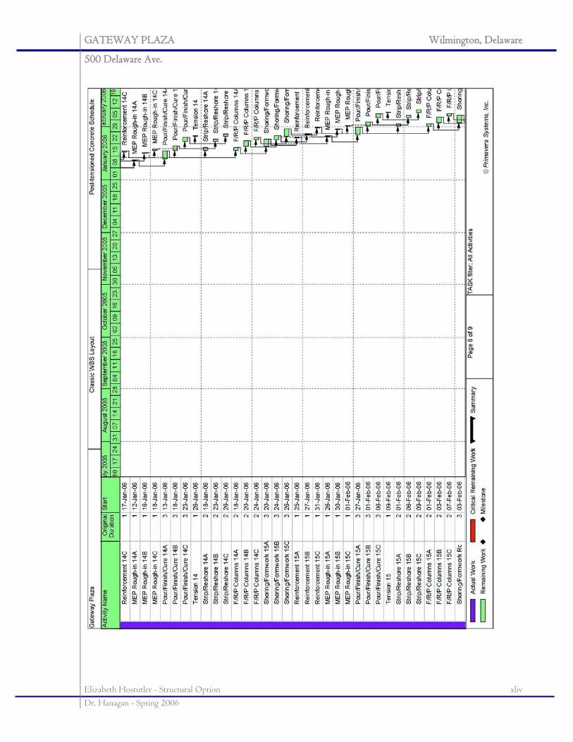
GATEWAY PLAZA Wilmington, Delaware
500 Delaware Ave.
Elizabeth Hostutler - Structural Option xliv Dr. Hanagan - Spring 2006
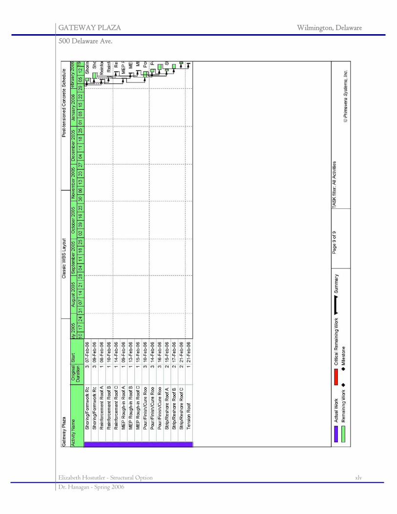
GATEWAY PLAZA Wilmington, Delaware
500 Delaware Ave.
Elizabeth Hostutler - Structural Option xlv Dr. Hanagan - Spring 2006
GATEWAY PLAZA Wilmington, Delaware
500 Delaware Ave.
Elizabeth Hostutler - Structural Option xlvi Dr. Hanagan - Spring 2006