Embed Size (px)
Citation preview

Gating ManualGating Manual
Publication # 512NORTH AMERICAN DIE CASTING ASSOCIATION

2 GatinG Manual
Although great care has been taken to provide accurate and current information, neither the author(s) nor the publisher, nor anyone else associated with this publication, shall be liable for
any loss, damage or liability directly or indirectly caused or alleged to be caused by this book. The material contained herein is not intended to provide specific advice or recommendations for any specific situation. Any opinions expressed by the author(s) are not necessarily those of NADCA.
Trademark notice: Product or corporate names may be trademarks or registered trademarks and are used only for identification and explanation without intent to infringe nor endorse the product
or corporation.
© 2006 by North American Die Casting Association, Arlington Heights, Illinois. All Rights Reserved.
Neither this book nor any parts may be reproduced or transmitted in any form or by any means, electronic or mechanical, including photocopying, microfilming, and recording, or by any
information storage and retrieval system, without permission in writing from the publisher.

3GatinG Manual
StEP 1 - DeteRmINe tHe CAstINg QuAlIty ReQuIRemeNts 9
StEP 2 - DeteRmINe tHe Flow PAtteRN AND loCAtIoN oF tHe INgAtes AND outgAtes 15
StEP 3 - DeteRmINe tHe segmeNt Volumes, CAVIty FIll tIme, AND CAVIty metAl Flow RAte 27
StEP 4 - mAtCH tHe PRoCess to tHe Flow RAte 35
StEP 5 - DeteRmINe tHe INgAte PARAmeteRs AND CHeCk FoR AtomIzeD Flow 37
StEP 6 - Do A PQ2 ANAlysIs IF DesIReD 45
StEP 7 - DesIgN tHe FAN AND tANgeNtIAl RuNNeRs 53
StEP 8 - DesIgN tHe oVeRFlows AND VeNts 75
StEP 9 - sImulAtIoN 81
tablE of contEntS
4 GatinG Manual
the die casting die is the heart of the die casting process. good gating design is essential for making good parts and leads the way to successful die casting. Conversely, poor gating design makes poor parts and contributes to the struggles in lowering scrap and meeting operational objectives. This manual describes what the engineer needs to know to develop a successful die casting gate design. the final gating design includes a complete set of information and drawings that the tool designer or toolmaker will use to construct the gating system in the die. There is a lot of thought and calculations that go into developing gating designs. The best designs come from die casting experience, NADCA gating formulas, and the guidelines presented in this text. gating design takes engineering effort and time. However, the time invested yields higher quality castings and shop floor productivity.
this text is intended for the process engineer, the tooling engineer, the die designer, the toolmaker, the production supervisor or whoever has input into the gate design. The more people in the organization who are on the same page for gating theory and practice, the better for a plant’s success. much of the information will concern cold chamber aluminum machines, since this comprises most of the world’s die casting activity. However, the gating techniques presented in this text apply to the zinc and magnesium alloys as well.
gating design is interactive with the process. Choices made in selecting the process factors will influence the gate design. tradeoffs are made in the developing the gating system to fit the plant’s processes. The analysis is done many times until the best and hopefully most robust design is achieved that works with the process factors chosen.
For example, selecting a gate area cannot be done properly without knowing the expected shot speed and plunger size; and this cannot be determined without knowing the desired fill time; and the fill time cannot be determined without knowing the quality requirements for the part and the machine capabilities. Changing one of these factors can affect the others.
the gating design effort includes selection of the flow pattern, the geometry and location of the ingates, runners, overflows, and vents. It also includes the development of the process parameters. If all is done right, then first shot success is expected with the process parameters very close to those calculated in the gating analysis.
other factors not considered in the gate design calculations are also important for casting quality. For example, if the die runs too hot or too cold due to spray conditions, cycle time, water flow, hot oil temperature, etc., or the process runs with an inconsistent cycle time, then the best gate design in the world may not work. even though these factors affect the casting quality, sometimes the gate design is considered at fault when defects occur. Thus, a gate design that has the right shape, that is in the right location, and has a good flow pattern, may not generate the expected quality if one or more of the other process factors are out of control. Changing the gate design is not always the answer to the problem, though some shops change the gate design as a way to solve almost all kinds of problems. For the designer, this means that the whole process needs to be examined before developing a gate design, and that the best results are obtained when the designer knows and makes allowances for the operational practices of the shop where the die is to be run.
introduction

5GatinG Manual
The calculations presented have been used for some time. The formulas and guidelines are based on empirical data and the results are successful especially when compared to the “let’s try this” technique.
It is tempting to short cut some of the methods presented, especially when they take more time and effort than past practice. However, these techniques have been proven to be effective and are always better if done carefully and completely. every effort should be made to obtain missing information such as a good definition of the casting quality requirements or machine performance information and to do the gate design as a thorough engineering project. This approach may cost more initially, but will always prove to be substantially cheaper in the long run when all costs are considered. seat of the pants or trial and error strategies are expensive and may never achieve scrap and operational efficiency goals.
small improvements in quality are critical in today’s market. older methods may achieve a 5 to 10% scrap rate, and may have been more than adequate for yesterday’s market. However, today’s market is a lot tougher with slimmer margins and has little room for operational error in order to make a profit. old methods won’t cut it any more and better gating designs are needed to survive and succeed in today’s market.
some believe that we cannot reach the very low levels of scrap without a lot of expensive trial and error die development costs. However, those companies that track the real costs of die development that comes from welding and re-cutting a gate or runner, will realize that the up front engineering costs of doing a proper gate design are a real bargain.
the first gate design should also be the permanent or last design. Although this goal isn’t achieved 100%, it will be the case in the great majority of designs if the NADCA formulas and guidelines are followed given that good equipment, good process control, and robust dies are also in place.

6 GatinG Manual
the Steps to a Good Gate design
The following steps are used to develop a proper gate design:
1. Determine the casting quality requirements. good gating designs start with knowledge of the customer requirements.
2. Determine the intended flow pattern and the ingate and the outgate locations. Visualize the flow of the metal through the die. segment the casting and determine the desired flow angles.
3. Determine segment volumes, the cavity fill time, and metal flow rate for each segment and for the entire casting.
4. Define the process constraints of the machine(s) intended to run the part – fast shot velocity, plunger sizes, and casting pressures. what are the plunger tip, pressure, fast shot velocity alternatives? Can the intended machine deliver the desired flow rate and pressure?
5. For each casting segment determine the flow rate, the ingate velocity, the apparent ingate area, the flow angle, the actual ingate area, and the ingate length and thickness. Check for atomized flow. Check the results for the entire casting against the process limits. Redo the analysis until satisfied.
6. If desired do a PQ2 gating analysis.
7. Design the runner system to support the ingate(s) working back to the biscuit of sprue.
8. Design the vent and overflow system.
9. If desired turn the design over to the simulation software to fine tune the design. the simulator may show flow patterns, hot and cold areas, and porous areas that were not visualized in Step 2.

7GatinG Manual

8 GatinG Manual

9GatinG Manual
1 StEP 1 – dEtErMinE thE caStinG Quality rEQuirEMEntS
Quality SPEcificationSthe designer needs to understand the customer’s casting quality specifications and how the
part functions in the application. How good does the finish have to be – plating quality, no cold flow, or some cold flow? How important is porosity – leak test, some porosity in certain areas, or no porosity requirement? what makes the part work in the application? what are the critical characteristics on the print?
to develop a good gate design, it is important that the casting specifications be defined as completely as possible. In many cases the customer is not an expert in die casting and looks to the die caster for guidance. Ideally, the die caster and customer make a joint effort to optimize the design and quality specifications for the casting. A Design FmeA is useful in this endeavor and should be done for every casting. After doing a Design FmeA changes are frequently made to make the casting design better and all parties are on the same page for what is required to make the casting work in the application. old methods such as “dumping the design over the transom” forces the die caster to make assumptions that can lead to sub-optimized gating designs resulting in sub-optimized production with high scrap rates, misunderstandings, etc.
sometimes quality specifications that are critical to the die caster seem insignificant to the customer. For example, an upgrade in the requirements for surface finish or porosity may change the machine needed, and will likely cause a change in the gating design. If this is discovered after the die is built and many irrevocable decisions have been made, any changes will be expensive for everyone concerned. It is incumbent for the die caster to ask the right questions.
there are two major defect problem areas in die casting -surface finish and porosity. some considerations for the designer about quality requirements in these areas are listed below:
SurfacE finiShsurface quality is always a concern and need to be considered in all gate designs. However,
the surface finish requirements can vary widely. there is a big difference in gating development between a chrome plated decorative zinc casting and a functional aluminum part.
since surface finish is subjective, the NADCA Product standards checklist C-8-2-06 is valuable in helping to develop a more specific standard for any given part. A copy of the checklist is shown on the next page.

10 GatinG Manual
StEP 1 – dEtErMinE thE caStinG Quality rEQuirEMEntS
caStinG SurfacE finiShinG SPEcificationSto be used in consultation with your caster (use in combination with Checklist C- 8 -1)*
checklist for finished die, SSM and Squeeze casting Part Purchasing
this Finishing Checklist provides a convenient method for assuring that important factors involved in the surface finishing of cast parts are evaluated and clearly communicated between the purchaser and the caster.
This checklist is for use in consultation with your die caster prior to estimat- ing production costs. use in combination with the Finishing Checklist C-8-2. Also review Checklists
t-2-1A and t-2-1B, for Die Casting Die specification, in section 2.
It should be used as a supplement to the essential dimensional and alloy specifications detailed on part prints submitted for quotation, since the listed factors directly affect the basis on which the casting quotation is made. the checklist may be reproduced for this purpose. your caster will clarify any item requiring explanation.
This checklist provides a numbering system in which the lowest numbered description for each requirement can be met at the lowest production cost, as follows:

11GatinG Manual
StEP 1 – dEtErMinE thE caStinG Quality rEQuirEMEntS
* The specification provisions and procedures listed in Section 7, “Quality Assurance,” should also be addressed.
Publisher grants permission to reproduce this checklist as part of a casting Request for Quotation or Production Specification .

12 GatinG Manual
StEP 1 – dEtErMinE thE caStinG Quality rEQuirEMEntS
there will be four gating design factors that affect the surface finish – flow pattern, cavity fill time, ingate velocity, and overflow size. these factors and their effects on surface finish will be discussed later in the manual. the intent here is to help the designer plan for surface quality requirements and to learn as much as possible about the finish required.
there will be some judgmental values to be established later for fill time, which is discussed in the next section, but the following will give some guidance.
Surface finishQuality requirements
Guidance for selections used during fill time
calculation
General considerations in flow pattern design
Average (some minor cold flow permissable)
middle to high end values of fill time
some minor lines and swirls are no problem
good (no cold flow visible) middle values of fill time minimum swirls, minimum flow lines
excellent (painting or plating grade finish)
shortest possible fill time No swirls, no flow lines, even in small areas
the decisions made later when establishing the cavity fill time will determine the machine capabilities needed, but the choice at this point is about “how good is good”, or what are the required surface quality levels.
the intent of reviewing the surface quality issues at this time is resolve questions that must be referred to the part designer. Changing the finish quality requirements later may involve changing machines or doing a different die design, so these issues need to be resolved early.
intErnal Quality or PoroSity conSidErationSthe porosity concerns need to be defined so the gate design can be developed accordingly. the
two types of porosity that will cause the most concern are shrink porosity and gas porosity.
shrink porosity occurs because cast metals shrink when they go from the liquid state to the solid state. since the metal freezes to the die steel first, the spaces left over at the end of solidification will be inside the casting and is called shrink porosity. They will be located at the last point to solidify in the hottest and thickest areas in the casting. The only way to feed more material into these spaces and reduce them is to shrink feed more metal during solidification. this is usually done with high pressure applied at the end of the shot. If the ingate is too thin and freezes prematurely, then the shrink porosity is left in the part.
shrink porosity can be exposed during machining. It can also cause sinks, leak test failures, and cracks. The gating system should allow delivery of metal under high pressure at the right location with high pressure to address the shrink porosity issues.
gas porosity comes from trapped air, steam, or volatized lubricant. Hydrogen gas porosity can be a problem in aluminum die casting, but the gas content from the other sources is often so large that hydrogen gas is a very small percentage of the total.

13GatinG Manual
StEP 1 – dEtErMinE thE caStinG Quality rEQuirEMEntS
gas porosity is often a concern for machined areas, or it may show up as blisters in other areas. with gas porosity the gate design issues include developing a flow pattern that doesn’t produce swirls or backfills and developing the proper venting and or vacuum system.
so definition of part quality requirements needs to be understood early as these requirements affect the gating design strategy and decision making process.

14 GatinG Manual

15GatinG Manual
StEP 2 – dEtErMinE thE flow PattErn and location of thE inGatES and outGatES2
GEnEral conSidErationSAll gating designs start with a grand plan for the metal flow through the die. where is the most
logical and available place for the metal to come in? where is the most logical and available place for the air to escape? what obstacles to the metal flow will be encountered inside the cavity? what pattern is best to satisfy the quality requirements? Visualizing the flow pattern is a critical step in the gating design process. when the flow pattern is defined, then the ingates and outgates can be located provide the desired pattern.
In visualizing the metal flow:
1. use as much of the parting line as possible deliver metal to where it is needed and to spread the heat out,
2. Take the shortest distance across the cavity, and
3. minimize diverging and converging flow paths.
Part of visualizing the metal flow paths is also visualizing the components that will feed the metal. Here are illustrations of the flow coming off a curve sided fan and tangential runner.

16 GatinG Manual
StEP 2 – dEtErMinE thE flow PattErn and location of thE inGatES and outGatES
the metal flow angle is shown in this figure.
A long rectangular part can be gated with a fan and two tangential runners.
Filling a corner can be done with a fan and possibly two tangential runners. Round parts present difficulties in getting the pattern right to prevent backfilling at the far end of the casting. the ingates need to vary in depth.

17GatinG Manual
StEP 2 – dEtErMinE thE flow PattErn and location of thE inGatES and outGatES
the overall metal flow plan can be drawn on the preliminary die design print.
of primary importance to the envisioned flow pattern are the quality issues. Flow needs to be directed to areas that need the best surface finish or to a location where there are porosity requirements. thus, any area that has special quality requirements should receive direct flow and should be close to the gate if possible.
the gate location should be such that there is as much unobstructed metal flow distance the area of concern. the metal loses a lot of energy when the flow impacts directly on a wall. Adjusting the parting line or moving the gate so the flow can avoid direct impact is worth the effort.

18 GatinG Manual
StEP 2 – dEtErMinE thE flow PattErn and location of thE inGatES and outGatES
In setting the flow pattern, the engineer should review the location of areas expected to be last to fill. these locations are always suspect for possible porosity and poor surface finish. In placing the part in the die, the last points to fill should be located where it is possible to place vents and overflows. Determining the location of the last points to fill is an important part of the flow pattern decision, and it is one of the major uses of simulation software.
uSinG cavity SEGMEntS to dEvEloP flow PattErnS and GatE locationS
the definition of the flow pattern and the gate locations includes dividing the casting up into segments. while the segmented flow plan is visualized, fan and tangential runner components that feed the ingates with flow angles are also visualized. segmenting the casting insures critical areas and difficult to fill areas are addressed and that segment flows are balanced with the runner components in mind. Best results are usually obtained by keeping the number of segments to a minimum – typically 2 to 4. each segment should have an ingate, and the design should be such that the flow from one gate fills just that segment.
Segments should be chosen by the following guidelines:
Quality issues. If a section of a casting has a different quality requirement than the rest of the casting, then consider making it a segment. For example, if a section has a very high quality surface finish requirement as compared to the rest of the casting, then it should be chosen as a segment.
Natural flow paths. look for ribs or thicker sections that will provide a natural path for metal flow. Also, look for obstacles that will force the metal to divert. evaluate the conditions in the natural metal flow paths. If the casting has an open area that divides the flow, first look at each side of the divided flow to see if there are different geometries for the two flow paths. For example, if the wall thickness on one side was double the wall thickness on the other side, then each side probably should be a separate segment.
Casting shape. segments should be used where two areas have substantially different wall thickness. Different segments are also appropriate if the flow distance is substantially different from one segment to another. Consider the path of the metal as it is reflected from wall to wall to develop the flow distance.
Any portion of the casting with features that are considered hard to fill, especially if these features are located at the end of the casting with the furthest flow distance, can be made into a separate segment.
In general, segments should be different from each other or fed by a particular runner. Different wall thickness, different flow length, different quality requirements, or different geometry, or different runner are typical reasons for selecting segments.
essentially, segments will divide the casting and are treated in the gating analysis as separate castings. each segment will have an ingate, and will be sized in direct proportion to the volume that it feeds relative to the other segments.

19GatinG Manual
StEP 2 – dEtErMinE thE flow PattErn and location of thE inGatES and outGatES
the gate areas should be such that each segment will have the same fill time and the concept of simultaneous fill is achieved. If the segments were engineered to fill with different times, then one segment’s flow will spill over into another segment causing swirls and backfills leading to poor fill and porosity.
A simple way to keep track of segment gate areas is to develop a table like the following:
Segment volume of Segment volume as a Percent Gate area for each Segment
#1 0.2 20% 0.07#2 0.3 30% 0.105#3 0.5 50% 0.175Total 1.00 100% 0.35
The fraction of the total volume of each segment is multiplied times the total casting ingate area to get the segment ingate area. the principal is to balance segment gate flow areas to segment volumes. This same principle is used when doing the gating for a multi-cavity die.
the reason for dividing the casting into segments can be seen in the following example:
on the left side is a casting with two equal gates. the casting is divided into two segments, with the large segment on the left being twice as large as the segment on the right. with equal flow, the right segment fills quicker, and after it is finished filling, the metal will flow as shown with the red arrow along the back side of the casting into the other segment, which will tend to be an area of cold flow and poor fill problems.
on the right is the same casting, but the gate areas have been adjusted to match the segment volumes.

20 GatinG Manual
StEP 2 – dEtErMinE thE flow PattErn and location of thE inGatES and outGatES
since segment A is twice as large as segment B, the gate for A is made twice as large as the gate for B, consequently the two segments finish filling at the same time, and cross flow between segments is minimized.
this concept of having the same fill time for all segments or proportioning gate flow areas to segment casting volumes is fundamental to good gate design. The same concept applies when designing gates for different cavities in the same die, where the design goal is to have each cavity finish filling at the same time. In this case, the gates for different cavities in the same die are sized in proportion to the cavity volumes.
experience will help to logically segment the casting. However, even for complex shapes, the number of segments is usually kept to 2, 3 or 4.
flow PattErn GuidElinES
Some general rules and guidelines for setting the flow pattern would be as follows:
1. Distribute the flow. the flow pattern should always be distributed and not focused into small jets with a few small narrow gates. These small jet gates are good for some kinds of porosity control, but unless the goal is to focus flow in a small area for porosity control, it is much better to use a distributed flow pattern. A distributed flow spreads out the ingate, which results in a wider and thinner gate. the heat is also distributed over a large area allowing for better temperature control and longer die life. Thin gates will not erode or “burn out” if the gate velocities are within NADCA guidelines. the minimum thickness in aluminum is about typically about .040, although it can be less if the metal is cleaned and filtered close to where it is ladled. zinc gates are typically about .015 to .020, although they can be thinner as with minature zinc. magnesium can be the same as zinc, but should start at about .02 to .04. Fan and tangential runners should be used to distribute the flow from the main runners. Chisel runners produce a solid jet stream that cause swirls, trapped gas and poor fill. wide ingates will also trap some gas, but the distributed flow pattern will also break up and distribute the trapped gas and the metal for better fill.

21GatinG Manual
StEP 2 – dEtErMinE thE flow PattErn and location of thE inGatES and outGatES
2. Direct the flow towards the critical quality areas. this is true whether the problem is porosity or surface finish. Surface finish. If one of the quality issues is a good surface finish, then direct flow from the ingate to the ares requiring good surface. the gate should be located as close to these areas as possible, and the flow should be as unobstructed as possible. If there is a choice about parting line location, it is important for the best finish if the flow is directed into the area of concern, as shown below.
Atomized flow is best for a good finish. If the metal slows down, the flow will drop out of the atonized flow range, and the finish will become less than optimal. the flow distance for good finish can be up to 7”. However, this distance depends upon the obstructions encountered, the metal temperature, the die temperature, the gate velocity, and the casting wall thickness. Incoming metal will not maintain good speed through more than about 2 or 3 reflections. metal velocities higher than normal will provide better finishes, however, with aluminum a high metal velocity can cause premature gate erosion and solder. High metal velocities with zinc and magnesium can cause some soldering. gate velocities should be kept at the high end of the range for the best finish but not exceed the high limit of NADCA guidelines. Porosity issues. For shrink porosity, the flow also needs to be directed right at the problem area. In this case, the gate should be thicker to delay ingate freezing allowing more time for shrink feeding to occur. the gate to runner ratio should also be large so there is more local heat. Runners with a 45° ramp to the gate can be used to maintain heat keeping the ingate from freezing too soon. while this approach keeps the gate area hot, it also tends to reduce die life around the ingate. A gate thickness of about .080” (2 mm) should be considered a mimimum for porosity control, and a thicker gate should be considered if it can be trimmed. A gate thickness of.125 in (3.2 mm) can usually be trimmed, and even thicker gates are possible with properly built trim dies or by sawing.

22 GatinG Manual
StEP 2 – dEtErMinE thE flow PattErn and location of thE inGatES and outGatES
A gate intended to feed shrink porosity should be located as close to the problem area as possible. A small but thick gate can be fed by a larger than normal runner in a location away from the main gate. The sole purpose of this kind of gate is to feed an area of possible shrink porosity, and it should not be counted on to improve surface finish.
Always try and flow the metal across the shortest path from ingate to outgate. the metal loses heat and drops in temperature as it traverses the cavity. Taking the shortest path minimizes thermal differences between the near and far sides of the flow, and also allows for the best control of the fill pattern within the cavity. the flow direction should be the short direction across the casting unless there are other flow restrictions or reasons for not doing so. this means that the first thought is to orient the casting so the gating would be on the long side.
the exceptions will be if there are natural impediments to flow in the short direction. For the shape below, where the internal squares represent cut outs in the casting, the metal flow would need to come from the end, the long way, instead of the short way across the casting, which would normally be preferable.
3. use the natural casting shape to direct the flow. this is an exception to the rule about flowing the short way. If, for example, the casting above had fins along the top that extended the long way, then the natural flow path is with the fins and the flow should be the long way instead of the short way. Be alert for natural flow paths, and try to use them. watch for thick sections that will guide the metal, for example, and try to design a flow path that will utilize this natural flow path.
4. It is important to keep casting wall thickness uniform, especially for large flat surfaces, when a good surface finish is required. sometimes part designers will specify a large thin section, but put a rather large tolerance on it. For example, the wall section of a large flat piece may be .080 “ +/- .010. It is a lot easier to make the casting at .088” thickness than at .072” thickness. If there are ribs or bosses on a wall sections, then the NADCA guidelines for wall thickness and radii are important for metal flow purposes. working with the tool maker to take advantage of print tolerances can help with filling the die and robustness of the casting process.

23GatinG Manual
StEP 2 – dEtErMinE thE flow PattErn and location of thE inGatES and outGatES
5. Follow the NADCA Product specification standards for Die Castings for draft and radius. these standards allow the casting to release from the die minimizing distortion. However, sometimes adequate radii make the difference between whether a casting has a flow pattern that works or not. the difference between having a radius and a sharp corner could be the difference between an acceptable casting and scrap. Having radii that conform to NADCA design recommendations also helps with die life. therefore, the minimum radius specified in the NADCA specifications should be followed for good flow pattern development. larger radii are especially valuable at the point where metal is expected to flow into bosses or fins. However, a word of caution – if radii are too large, cracks can occur due to shrink porosity at the base of the rib or vertical wall.
6. the high velocities in die casting mean the metal flow characteristics are dominated by momentum. this has a number of implications. For example, when considering the flow into a fin or boss on the top of a flat section, the metal will normally shoot past the boss, go the end of the casting, and then backfill and start to fill into the boss as as shown below left. the fin gets some flow early during casting fill, but may not really fill until the whole casting is pressurizing towards the end of fill. this makes it difficult to fill these features. sometimes it is necessary to change the geometry. For example, some die casters add a deflection boss to the casting to get the metal to deflect as shown below. Adding radii on the bottom of the fin or boss helps, but may not solve the entire problem as shown below right. when this is a problem, adding vacuum can be an effective solution because the trapped gas in the fin or boss resists the metal flow from coming in.
7. try to avoid gating directly on a vertical wall or on a core. the flow will eventually heat check or erode the die steel creating an undercut and cause ejection problems. However, if flow is required at this location, then the lesser of two evils is to gate on these features as the priority is to get the flow pattern right. the reflection from a wall will tend to go sideways and around the casting unless the metal impinges at close to a 90° angle. thus, only that portion of the flow that is perpendicular to the wall will tend to go up the wall. If the objective is to get the metal to go up the wall, then the gate must be carefully designed so most of the metal flow impinges on the wall at a 90° angle. Another approach is to turn the metal in the runner and ingate to flow metal with the wall. However, this strategy requires face milling as a secondary operation.

24 GatinG Manual
StEP 2 – dEtErMinE thE flow PattErn and location of thE inGatES and outGatES
8. Avoid mixing the metal flows between segments. the flow angles from adjacent segments should be coincident where they meet. Diverging metal flows from adjacent segments create weak fill areas resulting in poor fill and porosity. Converging metal flows from adjacent segments cause hot areas resulting in thermal control problems.
9. If possible, the flow should not impact on a gasket groove. gasket grooves generally have a tight tolerance, and can be easily eroded.
10. Casting areas behind a core or an opening in the casting where the metal flow will be split can be a problem. these areas are candidates for poor fill and porosity. If this is a concern, then the flow needs to come from two directions, as noted in the following sketch. this approach could be used for a plated zinc casting that needs a perfect finish, or for an aluminum casting with a large hole that gets machined where there can be no porosity exposed by machining.

25GatinG Manual
StEP 2 – dEtErMinE thE flow PattErn and location of thE inGatES and outGatES
inGatE locationSonce the desired flow pattern is established, then ingate locations can be placed with associated
metal flow angles. Note that flow angles cannot be greater than 45 degrees as will be discussed later.
except where an effort is made to shrink fill a local area for porosity, ingate thicknesses should be compatible with wide gates and distributed flow. gate thickness should not exceed 75% of the part thickness in order to trim without distortion or breakout. An ingate thickness of 50% of the part thickness is better for reducing trim distortion and breakout. If simulation is used later, then there may be some changes in the gate location as a result of information learned in simulation.
outGatE, ovErflow, and vEnt locationSthe ideal place for outgates, overflows, and vents is where the last of the metal will naturally
fill the die. this is a lot harder to visualize as the metal can get deflected inside during cavity fill. on the other hand, vents have a drawing effect on the metal flow pattern. Perhaps there are similar castings where the metal flow pattern can be read on cold start up shots and give insight as to where the ougates, overflows, and vents should be for the gating system being designed. Areas on the far end of the casting with anticipated poor fill and porosity problems will benefit with adjacent outgates and vents.

26 GatinG Manual

27GatinG Manual
StEP 3 – dEtErMinE thE SEGMEnt voluMES, cavity fill tiME, and cavity MEtal flow ratE3
SEGMEnt voluMESFor existing castings, segment volumes can be determined by cutting the casting up with a band
saw, weighing each segment, and calculating the segment volume. The volume of a segment may be calculated with the following formula.
volume (in3 ) = weight (lb)/density (lb/in3)
where, densities are: Aluminum = .096 lb/in3
zinc = .256 lb/in3
magnesium = .064 lb/in3
lead = .400 lb/in3
For new castings the easiest way to determine segment volumes is to use 3D CAD software to generate segment volumes. this method is fast and accurate. when many gating design scenarios are used and the casting is successively resegmented for each scenario, CAD makes the process fast and efficient. with 3D CAD and a comprehensive spreadsheet that calculates ingates, runners, outgates, and vents, many gating interations can be done quickly and efficiently. By doing many scenarios a better job of approaching the optimum gating design is done.
A more time consuming method would be to determine the casting volumes with a spreadsheet and a calculator. this method is slower and not as accurate as 3D CAD and gating design quality will suffer.
Planned overflows associated with each segment should be included in segment volumes. Including overflow volume with segment volume is called “metal through the gate” and yields a more conservative design. each segment volume with the planned overflows is placed into the spreadsheet and then summed to get the total casting volume.
cavity fill tiMECavity fill time is the time from when the metal begins to flow into the die until the cavity
is full. metal flow into a die casting die time is a race against time. As the metal enters the cavity and hits the die steel, it loses heat and drops in temperature. The metal must reach all extremities of the cavity before the metal temperature decreases to the point where the metal no longer flows and meshes with converging streams. If the race is lost, then poor fill and porosity appear in the casting. when determining the cavity fill time for a new casting whether by formula, table, or historical data, it is better to normally err on side of a fast fill time. the exception might be the case of porosity issues and feeding the far side of big cores on thick castings where fast fill times can actually make the castings worse.

28 GatinG Manual
StEP 3 – dEtErMinE thE SEGMEnt voluMES, cavity fill tiME, and cavity MEtal flow ratE
the fill time calculated by the methods presented here are considered to be maximum fill time, and not ideal fill time. the reason for this is because of varying flow distances and metal deflection within specific die casting cavities. general equations and tables cannot address specific flow distance and obstruction issues. so the fill time calculations by formula should be the upper limit for any gating design.
An important design consideration is that shorter fill times benefit surface finish provided the gates areas are proportional to segment volumes. A casting requiring a good finish needs a fast fill time and becomes the defining variable for the rest of the process selections.
Fast fill times can be constrained by the vents. there is a limit as to how fast air can flow through vents. sometimes fast fill times obtained by modern machines may require more venting area than can be installed in a given die. In these cases, chill blocks or a vacuum system need to be considered. This is discussed in the section on venting.
while fill time is the major factor affecting the surface finish, the factors affecting porosity may not be strongly affected by fill time. In the case where shrink porosity is the dominant quality issue, then the fill time need only be fast enough to get a good fill with an average finish. In fact, a slower cavity fill time may help porosity by allowing more air to escape through the vents and by filling with a higher per cent solids.
the NADCA formula contains factors the gating designer must assume. wall thickness, die temperature, metal temperature, and percent solids come from the designer’s judgment of what will actually happen when the casting is in production. thus, the calculated cavity fill values become a function of the designer’s experience and perception of actual floor practices. A good database from process engineering on the actual process conditions of the shop is valuable when used in conjunction with NADCA’s formula.
Deviations from the formula and recommendations should come from historical data which would be the best for knowing what works for a particular class of castings. the best fill time values may come from the process engineer who has run similar parts, and has a data base containing fill time numbers. when good fill time data is available, these values should supercede the NADCA formula values.
Feedback is important for any gating designer. the actual casting results for all designs relative to cavity fill time should be critiqued. what worked? what did not work so well? Improving gating skills is a journey. over time gating designers get better at determining cavity fill time values for any particular operation.
some castings are tolerant of fill time variations, while some are not. However, gating designers should give all castings serious thought to a proposed cavity fill time especially if the casting is plated of leak tested.
J. A. wallace (Practical Application and the results of metal flow and gating research – 1965) developed the basic NADCA fill time formula. e. A. Herman published the current version in his book, gating Die Casting Dies. this basic fill time formula is:

29GatinG Manual
StEP 3 – dEtErMinE thE SEGMEnt voluMES, cavity fill tiME, and cavity MEtal flow ratE
t = k {ti - tf + sz
}TTf - Td
where:
k = empirically derived constant related to the die steel
t = wall thickness of the casting
t = maximum fill time
tf = minimum flow temperature of the metal alloy
ti = metal temperature at the ingate
td = Die surface temperature just before the metal arrives
s = Percent solids at the end of fill
z = solids units conversion factor, degrees to %
From observation of the formula, cavity fill time is proportional to:
1. Casting thickness, t. the thicker the wall, the longer the time can be. the thinner the wall, the shorter the time must be.
2. metal temperature, tj. the hotter the metal, the longer the time can be. the colder the metal, the shorter the time must be.
3. Die temperature, td. the hotter the die, the longer the time can be. the colder the die, the shorter the time must be.
4. Percent solids, s. the higher per cent solids at the end of the fill, the longer the fill time. the lower the percent solids, the shorter the fill time.
tf, the minimum flow temperature of the alloy is a constant. k is the constant of proportionality and is related to the thermal conductivity of the type of die steel used. Note that the NADCA formula does not address flow distance or obstructions within the cavity to the flow.
Values for the variables in the fill time formula can be taken from the following tables:
selecting the values used in the formula depends on the judgment of the gating designer. the following are some guidelines:
(“t”) Casting wall thickness. the following methods are used in calculating this value:
Thinnest wall section found anywhere on the casting. This method is conservative, and will yield shorter fill times than may be required. using the thinnest wall section in NADCA’s formula decreases cavity fill time and will increase machine power requirements. A very fast fill time may require a fast shot velocity that is beyond the machine’s upper limit.

30 GatinG Manual
StEP 3 – dEtErMinE thE SEGMEnt voluMES, cavity fill tiME, and cavity MEtal flow ratE
Average casting wall thickness. If the casting wall thickness is fairly uniform, and there are no specific surface quality issues, then the average wall thickness can be used. However, for typical castings with unequal wall thickness, the time may be too slow resulting in poor fill in the thin areas or in areas at the far end of the flow.
Average thinnest wall thickness. this is the method recommended. most castings have unequal wall thicknesses. using the thinnest part wall section that can be found on the casting would place unrealistic burdens on the die casting machine for flow rates and would not be necessary to make the casting. If the casting thickness is uneven, then calculate an average thickness of the thinner wall sections.
(“tf”). minimum flow temperature of the alloy. this value is found in the charts.
(“ti “) temperature of the metal at the gate. on cold chamber machines there is a metal temperature drop between the holding furnace and the ingate. The drop for aluminum can be as little as 25°F (14°C) or as much as 70°F (39°C) depending on the amount of metal pored, the ladle traverse time, the type of ladle cup, the pour rate, the shot delay time, the sleeve and die temperatures, the slow shot velocity and length, and the length and geometry of the runners.
The following temperature drop values are suggested for typical operations: Aluminum (cold chamber) = 50°F (28°C)
Aluminum (cold chamber) = 50°F (28°C)
zinc (hot chamber) = 30°F (17°C)
magnesium (cold chamber) = 80°F (44°C)
5. (“Td “). The temperature of the die surface just before the metal arrives. This is an another difficult estimate. In addition, die temperature varies across the cavity. At any one area the die temperature before close is a fun on of cycle me,die spray,coolant flow rate,etc.The process engineer’s data again would be helpful for similar parts or for general plant conditions in coming up with this number. lacking data it is suggested that the designer use 500oF (260oC) for aluminum and magnesium and 400oF (204oC) for zinc.
6. (“s”) the percent solids at the end of fill. this value represents the solidified portion of metal at the end of the flow path at the time when the cavity is full. the higher this factor, the worse the surface finish. However,a higher value of “s” helps shrink porosity as there is less metal to shrink in changing state from liquid to solid. A higher “s” value yields a longer cavity fill time with the other factors held constant. If “s” is set at 50%, then theoretically 50% of the metal at the end of fill will be solid, andwill have completed its density change yielding less shrink porosity.

31GatinG Manual
StEP 3 – dEtErMinE thE SEGMEnt voluMES, cavity fill tiME, and cavity MEtal flow ratE
alloy Empirical constant, KP-20 h-13/h-21 tungsten
sec/mm sec/in sec/mm sec/in sec/mm sec/inmg 0.0252 0.640 0.0124 0.311AI 360,380,384
0.0346 0.866 0.0124 0.311
Al390 0.0346 0.866 0.0124 0.311zn 12,27 0.0312 0.799 0.0346 0.866 0.0124 0.311zn 3,5,7 0.0312 0.799 0.0346 0.866 0.0124 0.311Fe 0.0346 0.866 0.0124 0.311Cu 60/40 0.0346 0.866 0.0124 0.311Cu 85-5-5-5 0.0346 0.866 0.0124 0.311Pb 0.0156 0.39 0.0173 0.433
alloy Metal injection tempti
Min. Flow Temp.tf
Die Cavity Temp.td
Solids factorZ
oc of oc of oc of oc/% of/%mg 650 1200 510 1050 340 650 3.7 6.6AI 360, 380, 384
650 1200 570 1060 340 650 4.8 8.6
Al390 720 1325 595 1100 355 675 5.9 10.6zn 12,27 565 1050 445 835 260 500 3.2 5.7zn 3,5,7 405 760 382 720 230 450 2.5 4.5Fe 1540 2800 1370 2500 980 1800 6 10.8Cu 60/40 955 1750 900 1650 510 950 4.7 8.4Cu 85-5-5-5
1035 1900 930 1710 515 960 4.7 8.4
Pb 315 600 280 540 120 250 2.1 3.8
the table below shows some recommended values for “s”. Note also that “s” is entered in the formula as a whole percent, with no decimal point.
Suggested Percent Solids “S” (use lower values for good finish)wall thickness (inches) al Mg Zn
.01-.03” 5% 10% 5-15%
.03-.05” 5-25% 5-15% 10-20%
.05-.08” 15-35% 10-25% 15-30%
.08-.125” 20-50% 20-35% 20-35%
For typical aluminum castings with a commercial finish, the values for “s” will be between about 20 and 50. A percentage below 20 is needed only for the very thin wall castings, while a percentage

32 GatinG Manual
StEP 3 – dEtErMinE thE SEGMEnt voluMES, cavity fill tiME, and cavity MEtal flow ratE
for “s” of about 20 to 35 will work for typical castings with a wall thickness over about .125 inches and up. the lower value would be used for a better finish, or for a longer metal flow path.
one factor not included in the fill time formula is the metal flow distance. this is the distance of the path the metal takes to reach the last point to fill, or the end of travel for the segment or casting area of concern. the path includes deflections and angle flow paths, and is not necessarily the shortest distance.
while the ability to flow through long distances is mostly determined by the average wall thickness along the flow path, some other factors that affect the ability of the metal to flow long distances are: the die temperature, the metal temperature, and the gate velocity at the start of the flow.
An empirical guide for evaluating flow distance and wall thickness is to divide the flow distance by the average wall thickness along the flow path. this is a rough guideline as it assumes the die temperature, the metal temperature, and the ingate velocity are within typical operating ranges. For aluminum, if this number is below about 150, then the flow distance should not be a big factor. If the number is between 150 and 300, then there will be increasing difficulty in making the part and the fill time needs to be kept short in order to make the part. If the number is over 300, it could be very difficult to make the part even with a short fill time. Note that these numbers are approximate and are intended to help the designer be aware of potential problems with a long flow distance in choosing the cavity fill time.
For some thin wall parts, the short fill time requirements will force some high metal velocities. the following example shows how to use the flow distance number and to make adjustments.
An aluminum pan used in a bread-making machine has a .080 inch wall with a flow distance of 23 inches. the metal is directed up one side and down the other. the die runs cold (400°F or 204°C) because of the thin wall, low metal volume, and no hot oil. the normally selected values for calculating fill time for a wall thickness of about .080 and an “s” of about 15% would calculate a fill time of .026 seconds. the flow distance number is 287, which indicates that this is a difficult part that should have a minimum fill time. this could be done by reducing “s” to the minimum of 5%, which would give a fill time .017 seconds. this fill time is confirmed by historical data, which suggests a fill time of less than .020 seconds is needed, so a fill a maximum fill time of .017 seconds is used. the change in fill time is only .009 seconds. However, the percent fill time decrease of 38% is significant.
A spreadsheet can be used to calculate the fill time formula. NADCA provides a cavity fill time spread sheet in the gating class.
33GatinG Manual
StEP 3 – dEtErMinE thE SEGMEnt voluMES, cavity fill tiME, and cavity MEtal flow ratE
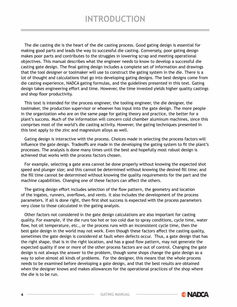
For the process engineer, there will be some discrepancy between the calculated value of fill time and the value taken from a typical monitoring system. the fill time value taken from a monitoring system includes the plunger’s deceleration time, while the calculated fill time from the formula is a theoretical value that assumes that the plunger speed stays constant throughout fill.
usually the surface finish is determined in the first part of the fill when the plunger speed is high. this is the speed that is important for a good finish, and this is the plunger speed needed to meet the fill time calculated from the theoretical maximum fill time calculations.
The compaction of the metal in the cavity is done while the plunger slows down, and this portion primarily affects the internal porosity rather than the surface finish. thus, for practical purposes, the plunger speed during the first part of cavity fill should match the cavity fill calculations.
If a partial fill under slow speed conditions is being used as a way to reduce porosity for thick walled castings, then fill time is difficult to measure. It may also be difficult to get a good surface finish because of the long time lapse during the prefill conditions.
the fill time calculation from the formula can be accurate if care is used in selecting the values. experience with feedback from casting floor data will improve the results. this calculation should be done for every gate design effort.
the following table is useful for picking a cavity fill time. the table is based on the cavity fill time formula. If in doubt about a fill time to use, use the chart value and reduce it by 25%.
average wall thickness (inches)
fill times in SecondsZinc 3,5,7 aluminum Magnesium
0.01 - 0.03 <.015 - <.0200.04 - 0.05 0.02 - 0.026 0.0173 - 0.0417 0.0132 - 0.02090.06 - 0.08 0.0245 - 0.0529 0.0296 - 0.0845 0.0221 - 0.04130.09 - 0.125 0.0468 - 0.085 0.0553 - 0.1458 0.0366 - 0.07070.13 - 0.15 0.075 - 0.125 0.0956 - 0.2082 0.0579 - 0.0997

34 GatinG Manual
flow ratESgiven the segment volumes and cavity fill time, the flow rate for each segment and for the
entire casting can be calculated.
Qi = vi / t
where,
Qi = flow rate of a segment (in3/sec)
Vi = volume of a segment volume (in3)
t = cavity fill time (sec), and
Q = ∑( Qi) = flow rate for the entire casting (in /sec)
This data is entered into the gating spreadsheet.

35GatinG Manual
StEP 4 – Match thE ProcESS to The Flow RaTe.4
ProcESS factorS and liMitSFor the die casting machine(s) intended to cast the part there are parameter choices. the
casting pressure and fast shot velocity limit can be changed by changing the accumulator pressure. The fast shot velocity can be changed with the shot valve. There are ranges of plunger tip diameters available that yield varying metal pressures and flow rates. what accumulator pressure, and sleeve/plunger tip diameter should be used to satisfy the flow rate calculated in step 3 (cavity fill time) and to address the pressure issue from step 1 (quality requirement). A way to choose plunger tip diameters is make a spreadsheet showing the options.
Required Flow Rate = xxx in3/sec,
Desired metal pressure = x.x tons/in2
Accumulator pressure = xxx lb/in3
Plunger(in)
Plunger area (in2)
required fast Shot velocity (in/sec)
final Metal Pressure (tons/in2)
x.xx xx.x xxx x.xx.xx xx.x xxx x.xx.xx xx.x xxx x.xx.xx xx.x xxx x.x
To do the spreadsheet the relationship between the accumulator pressure and the metal pressure needs to be known. This information can be obtained from the machine’s manual for the intended die casting machine. once the chart is constructed choices can be made. A die casting machine has a normal range and maximum limit for the fast shot velocity. this information comes from process engineering.
100 in/sec, then 80% or 80 in/sec should be used in the gating analysis. the gives some wiggle room if more fast shot is needed to make the part than the gating analysis indicates. The other factor to look at is final metal pressure. For normal aluminum castings 4 tons/in2 intensified pressure is used. If porosity is a quality issue or leak testing is required, then 5 tons/in2 final metal pressure should be used.
the first question to ask when reviewing the spreadsheet is can the machine deliver the flow rate required. If the machine can not deliver the flow rate, then another machine needs to be found or the cavity fill time in Step 3 needs to be increased.

36 GatinG Manual
StEP 4 – Match thE ProcESS to The Flow RaTe.
Assuming the machine can deliver the flow rate, then select a plunger diameter that gives a good fit for fast shot velocity and final metal pressure. other issues to consider in making this analysis are:
Can the die casting machine hold the metal at the proposed final metal pressure? what will be the tonnage on each tie bar with the proposed die design and casting pressure? If the machine can’t hold the metal, then surface finish and porosity quality standards will be difficult to meet regardless of the quality of the gating system.
Can the accumulator pressure be lowered and still have sufficient fast shot velocity? Casting the part with the least amount of pressure and fast shot velocity allows the die cast machine to run more smoothly with less mechanical stress and strain. This is a cost savings opportunity for die casters who normally set the injection and die close pressures to the maximum regardless of the part being cast.
In choosing a plunger tip diameter, what will the per cent fill of the sleeve be. the greater the per cent fill, the less air needs to be vented and the lower the probability for trapped residual air at the end of the shot. In addition, a higher percent sleeve fill conserves heat with less metal temperature drop from the furnace to the ingate.
these process decisions may appear to be complicated. However, if the gating designer knows the capabilities of the intended machine(s) and gives some thought to the tradeoffs of casting pressure, fast shot velocity, and sleeve per cent fill, then intelligent choices are made and the gating system is engineered to work for the intended machine. The objective at this point is to know that the die casting machine can deliver the casting flow rate calculated in step 3 and metal pressure in the cast of porosity from Step 1 without undo stress to the machine.
If the machine can’t deliver the desired flow rate and metal pressure, then the cavity fill time has to increase or a more powerful machine used.

37GatinG Manual
StEP 5 – dEtErMinE thE inGatE ParaMEtErS and chEcK for aToMizeD Flow.5
the next step in the gating analysis is to continue setting up a spreadsheet by segments with flow rate (Q), ingate velocity (Vg), apparent ingate area (Aag), flow angle (Af), actual ingate area (Ag), ingate length (lg), ingate thickness (tg), and atomization factor (J).
Segment Flow Rate (in3/sec)
ingate velocity (in/sec)
apparent ingate area (in2)
Flow angle (deg)
ingate area (in2)
x xxx xxx x.xx xx x.xxx xxx xxx x.xx xx x.xxx xxx xxx x.xx xx x.xxTotals xxx x.xx
Segment Flow Rate (in3/sec)
ingate velocity (in/sec)
ratio length/thickness
atomization factor
x x.xxx x.xxx xx xxxxx x.xxx x.xxx xx xxxxx x.xxx x.xxx xx xxxx
SEGMEnt flow ratEthese numbers come from step 3.
inGatE vElocitythe gating designer chooses an ingate velocity for the casting. Normal ranges for ingate
velocities are shown in the following chart. The ingate velocity selected should fall within these ranges.
alloy normal ingate velocity (in/sec)Aluminum 700 to 1600zinc 900 to 2000magnesium 1000 to 2000

38 GatinG Manual
StEP 5 – dEtErMinE thE inGatE ParaMEtErS anD CheCk FoR aToMizeD Flow.
Higher velocities are chosen for thin walled castings that require a good surface finish, where the travel from the near to the far end of the casting is long, or where the geometry is complicated and the metal will encounter deflections. when using higher velocities more machine power will be required and die erosion around the ingate will occur sooner.
lower velocities will require less machine power and die erosion around the ingate will occur later. lower ingate velocities are more economical using less power and lower tool maintenance and replacement costs.
thus, choosing an ingate velocity has to do with the quality requirements and the geometry of the casting. Historical gate velocity data would be helpful for the gating designer. troubles occur when the chosen ingate velocity is not within the recommended range. The ingate velocity may be changed for different gating scenarios. later in the analysis the ingate velocity in combination with the ingate thickness is tested for atomized flow.
aPParEnt inGatE arEaThe apparent ingate, Aapp, for each segment is calculated.
Aappi = Qi / Vg
where,
Aappi = apparent ingate area of a segment (in2)
Qi = flow rate of a segment volume (in3/sec)
Vg = ingate velocity (in/sec), and
These numbers are calculated in the spreadsheet.
flow anGlESthe metal flows into each segment at some angle, which is measured from an axis perpendicular
to the parting line and can range from 0 to 45 degrees. Flow angles of an existing casting can be observed in a cold start up shot. In step 1 the flow plan was visualized. this plan included specific flow angles in each segment.
these flow angles are entered into the spreadsheet.
actual inGatEthe metal velocity at an angle coming off the ingate can be represented as a vector with
magnitude and direction. this flow vector can be broken into two vectors, one normal to the ingate and one parallel to the ingate. The vector normal to the ingate represents the metal actually going into the die. the normal vector = Cos(θ) * flow vector and is illustrated as follows:

39GatinG Manual
StEP 5 – dEtErMinE thE inGatE ParaMEtErS anD CheCk FoR aToMizeD Flow.
To arrive at the actual ingate area for each segment we use:
Agi = Aappi / Cos (θ), and
Ag = ∑ (Agi)
where,
Agi = actual ingate area of a segment (in2)
Aappi = apparent ingate area of a segment (in2)
θ = flow angle rate of the segment (deg)
Ag = total ingate area (in2)
These numbers are calculated in the spread sheet.
inGatE lEnGth & thicKnESSThe ingate area is the product of the ingate length and the ingate thickness.
Agi = lgi * tdi
where,
Agi = actual ingate area of a segment (in2)
lgi = ingate length of a segment (in)
Tgi = ingate thickness of the segment (in)
Perhaps the ingate length is known or desired from Step 1. Then Tgi = Agi / lgi. Perhaps we have a desired ingate thickness, then lgi = Agi / tgi. Perhaps for a particular scenario we have a compromise between the two.
These numbers are entered and calculated in the spreadsheet.

40 GatinG Manual
StEP 5 – dEtErMinE thE inGatE ParaMEtErS anD CheCk FoR aToMizeD Flow.
RaTio ingaTe lengTh: ThiCkneSSIf the ratio of the segment ingate length to the ingate thickness length is less than 10, then the
ingate depth should be corrected.
lgi / tgi > 10
where,
lgi = segment ingate length (in)
Tgi = segment ingate thickness (in)
this condition does not occur very often. Distributing the flow over a large area of the casting normally yields length to thickness ratios much higher than 10.

41GatinG Manual
StEP 5 – dEtErMinE thE inGatE ParaMEtErS anD CheCk FoR aToMizeD Flow.
inGatE vElocitythe ingate velocity required in die casting is much different than that required for other casting
processes. In other processes such as permanent mold, the goal is to reduce turbulence to reduce trapped gas. the cavity is filled slowly and requires a thick wall and gate. Die castings have relatively thin walls, thin gates, and rapid heat absorption by the die steel.
Cavity fill in die casting dies is fast with a range of 10 to 150 milliseconds. Instead of a solid flow front as in permanent mold, the die casting process sprays the metal into the die.
In permanent mold the metal flow though a large gate is a solid front with laminar flow. As the metal velocity through a smaller gate is increased, the metal front breaks up and the flow consists of course and relatively large particles. this is called the course particle range. In die casting, course particle range flow produces questionable castings with excessive internal porosity and poor surface finish. As the metal velocity is increased further, there is a point where atomized flow off the ingates begins. the course particles are broken up and the stream of metal consists of fine particles at very high velocities. while this very turbulent flow may appear to be undesirable for trapped gas, it is the flow produces successful die castings. In die casting, the ingate and the process are engineered to deliver atomized metal flow to the cavity.
If some metal dribbles through the gate before the fast shot reaches its terminal velocity, the metal may prematurely freeze at the gate or in the cavity. this will cause cold flow and laminations. Thus, the metal velocity should be accelerated early enough through the runner system so that the metal is at its final velocity before it reaches the gate and the metal is atomized through the gate.
In some cases, an operational setting will be used such that the cavity is partially filled (usually about 10% to 15%) with low velocity, and then the metal is accelerated to atomized flow velocities. this is done to reduce trapped gas porosity. where this is successful, there is a relatively thick wall (greater than .160 in., or 4 mm) and thick gate, and the gate is on the bottom of the casting going into a thicker wall section. this process setting for partial fill under low turbulence conditions can sometimes generate a reduction in gas porosity. The gate design, however, should be done for the standard atomized flow conditions even if it is expected that the partial fill process setting will be used.

42 GatinG Manual
StEP 5 – dEtErMinE thE inGatE ParaMEtErS anD CheCk FoR aToMizeD Flow.
on some castings, it is possible to have a very large gate, and to fill the casting with slow non- turbulent flow. this will not provide high quality surface finish, but when combined with the high-pressure capability of the typical die casting machine, it can provide excellent internal quality. this technique is called squeeze casting, although there can be many different versions of the slow fast fill methods.
the very long fill times used in some of these methods mean that the wall thickness must be greater than typical die casting and the surface finish requirements are not as good. the method also results in very high die temperatures that shorten die life. this technique typically uses metal pressure from 15,000 to 25,000 lb/in2. with careful use of die coatings, it can be done with the more common low iron alloys such as the 356 or 357 alloys. the non-turbulent fill and very low gas porosity results in a casting that can be heat treated or welded with the potential for higher elongation and some increase in tensile strength after heat treating.
the slow fill techniques are now done often enough that the line between squeeze casting and regular die casting is somewhat blurred. A combination of very large gates, low velocity fill at the start and higher velocity for the final fill will work for some part shapes. However, the gate design techniques presented here are for conventional die casting and atomized flow.
the calculation of the minimum gate velocity needed to reach the atomized flow region can be done from the following formula, which was developed from some earlier research.
vg1.71 * tg * p > J
where,
Vg = the ingate velocity (in/ sec)
Tg = the ingate thickness (in)
p = the density of the metal (lb/in2)
J = the atomization factor
Values of J are based on experimental work in copper alloys. e. A Herman calculates “J” for each alloy as:
alloy J factormagnesium 275Aluminum 400zinc 475
most proposed gating systems will have a J Factor well above these minimums. Industry practice uses gate velocities and thickness’ that yield a minimum J Factor of 750 which is conservative and is recommended for normal gating analysis. The following table shows the relationship of gate thic kness and gate velocity if 750 is used in the atomization equation.
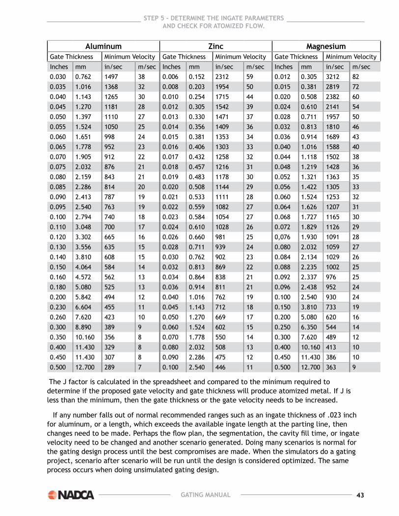
43GatinG Manual
StEP 5 – dEtErMinE thE inGatE ParaMEtErS anD CheCk FoR aToMizeD Flow.
aluminum Zinc Magnesiumgate thickness minimum Velocity gate thickness minimum Velocity gate thickness minimum VelocityInches mm in/sec m/sec Inches mm in/sec m/sec Inches mm in/sec m/sec0.030 0.762 1497 38 0.006 0.152 2312 59 0.012 0.305 3212 820.035 1.016 1368 32 0.008 0.203 1954 50 0.015 0.381 2819 720.040 1.143 1265 30 0.010 0.254 1715 44 0.020 0.508 2382 600.045 1.270 1181 28 0.012 0.305 1542 39 0.024 0.610 2141 540.050 1.397 1110 27 0.013 0.330 1471 37 0.028 0.711 1957 500.055 1.524 1050 25 0.014 0.356 1409 36 0.032 0.813 1810 460.060 1.651 998 24 0.015 0.381 1353 34 0.036 0.914 1689 430.065 1.778 952 23 0.016 0.406 1303 33 0.040 1.016 1588 400.070 1.905 912 22 0.017 0.432 1258 32 0.044 1.118 1502 380.075 2.032 876 21 0.018 0.457 1216 31 0.048 1.219 1428 360.080 2.159 843 21 0.019 0.483 1178 30 0.052 1.321 1363 350.085 2.286 814 20 0.020 0.508 1144 29 0.056 1.422 1305 330.090 2.413 787 19 0.021 0.533 1111 28 0.060 1.524 1253 320.095 2.540 763 19 0.022 0.559 1082 27 0.064 1.626 1207 310.100 2.794 740 18 0.023 0.584 1054 27 0.068 1.727 1165 300.110 3.048 700 17 0.024 0.610 1028 26 0.072 1.829 1126 290.120 3.302 665 16 0.026 0.660 981 25 0,076 1.930 1091 280.130 3.556 635 15 0.028 0.711 939 24 0.080 2.032 1059 270.140 3.810 608 15 0.030 0.762 902 23 0.084 2.134 1029 260.150 4.064 584 14 0.032 0.813 869 22 0.088 2.235 1002 250.160 4.572 562 13 0.034 0.864 838 21 0.092 2.337 976 250.180 5.080 525 13 0.036 0.914 811 21 0.096 2.438 952 240.200 5.842 494 12 0.040 1.016 762 19 0.100 2.540 930 240.230 6.604 455 11 0.045 1.143 712 18 0.150 3.810 733 190.260 7.620 423 10 0.050 1.270 669 17 0.200 5.080 620 160.300 8.890 389 9 0.060 1.524 602 15 0.250 6.350 544 140.350 10.160 356 8 0.070 1.778 550 14 0.300 7.620 489 120.400 11.430 329 8 0.080 2.032 508 13 0.400 10.160 413 100.450 11.430 307 8 0.090 2.286 475 12 0.450 11.430 386 100.500 12.700 289 7 0.100 2.540 446 11 0.500 12.700 363 9
the J factor is calculated in the spreadsheet and compared to the minimum required to determine if the proposed gate velocity and gate thickness will produce atomized metal. If J is less than the minimum, then the gate thickness or the gate velocity needs to be increased.
If any number falls out of normal recommended ranges such as an ingate thickness of .023 inch for aluminum, or a length, which exceeds the available ingate length at the parting line, then changes need to be made. Perhaps the flow plan, the segmentation, the cavity fill time, or ingate velocity need to be changed and another scenario generated. Doing many scenarios is normal for the gating design process until the best compromises are made. when the simulators do a gating project, scenario after scenario will be run until the design is considered optimized. The same process occurs when doing unsimulated gating design.

44 GatinG Manual
StEP 5 – dEtErMinE thE inGatE ParaMEtErS anD CheCk FoR aToMizeD Flow.
A special gating case occurs with long castings and small casting volumes such as chrome plated automotive body side molding. In this case the ingates will calculate to be very thin because of the long ingate length and small cavity volume. Ingate velocities exceeding the normal ranges would be needed to atomize the metal. This would demand high machine power and would erode the ingate die steel if attempted. This remedy for this case is comb gating.
At this point in the gating analysis the ingate width and length have been determined. The gate velocity is within the normal range. the flow is atomized, and it is known that the intended machine can deliver the flow with a chosen plunger tip.

45GatinG Manual
StEP 6 – do a PQ2 analySiS if dESirEd6
the goal of the PQ2 analysis is to match the die’s designed gating system to the machine’s total hydraulic system. In the analysis P stands for metal pressure and Q stands for metal flow rate. the molten metal flow rate through an orifice such as an ingate is a function of the pressure on the molten metal - the higher the pressure, the higher the flow rate. However, the relationship of pressure and flow rate is not linear. the governing equation for fluid flow through an orifice or ingate is Bernoulli equation.
Pm = ( ρ / 2 g) * ((Q / (ag * cd ) ) 2
where,
Pm = metal pressure (lb/in2)
ρ = metal density (lb/in3)
g = gravitational constant (in/sec2)
Q = metal flow rate (in3/sec)
Agapp = apparent area of the ingate (in2)
Cd = coefficient of discharge
the expression in Bernoulli’s equation (Q / Ag) is equal to the ingate velocity Vg. so the equation can also be written as:
Pm = ( ρ / 2 g) * ((Vg / Cd ) )
From observation of the Bernoulli’s equation:
metal pressure required is directly proportional to metal density.
Increasing the metal pressure increases the flow rate. Decreasing the metal pressure decreases the flow rate. the relationship is non-linear.
Increasing the apparent ingate area, Agapp, decreases metal pressure, Pm needed. Decreasing the ingate area increases the required pressure. the relationship is non-linear.
Increasing the coefficient of discharge, Cd, with a more efficient metal and hydraulic system decreases the pressure required. Decreasing the coefficient of discharge with a more inefficient metal and hydraulic system increases the pressure required. the relationship is non-linear.

46 GatinG Manual
StEP 6 – do a PQ2 analySiS if dESirEd
Increasing the metal pressure, increases the ingate velocity, Vg. Decreasing the metal pressure, decreases the ingate velocity required. the relationship is non-linear.
Values used for liquid density are:
Aluminum = .093 lb/in3
zinc = .221 lb/in3
magnesium = .063 lbs/in3
the gravitational constant “g” is 32.2 ft/sec2, or 386.4 in/sec2
the coefficient of discharge (Cd) is a measure of inefficiency of the metal delivery and machine hydraulic system. It is the ratio of the flow in the actual machine and die to an ideal fluid system that has no friction.
Common values for Cd for die casting applications are:
Cold chamber aluminum = .45 to .5
Cold chamber magnesium = .45 to .5
Hot chamber zinc or mag = .55 to .65
the following graph shows the non-linear relationship between metal pressure and flow.
special graph paper with a non-linear Q2 scale makes the P and Q2 relationship linear.

47GatinG Manual
StEP 6 – do a PQ2 analySiS if dESirEd
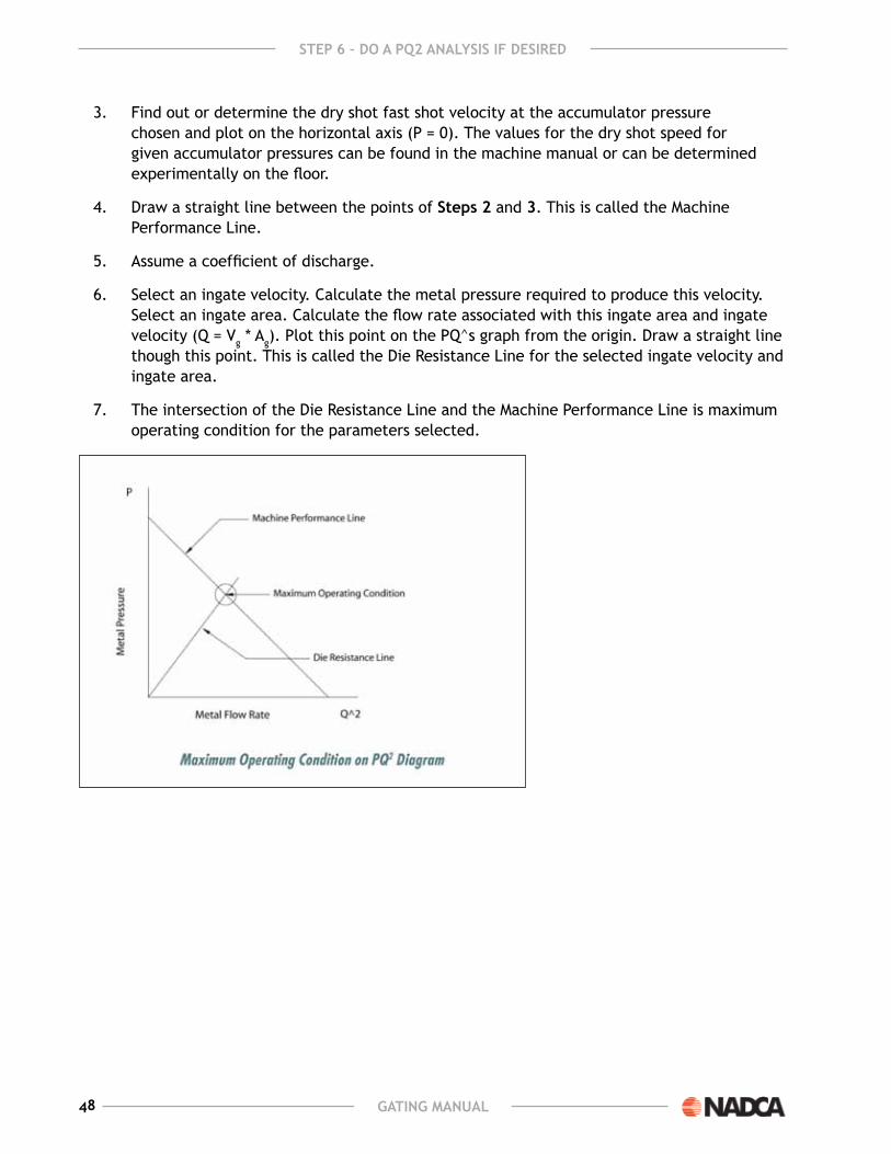
the PQ2 gating analysis using graph paper or a computer generated graph is:
1. obtain the appropriate PQ2 graph paper for the machine and die to be analyzed.
2. Determine the accumulator pressure and convert the accumulator pressure to metal pressure for a selected plunger diameter. Plot the metal pressure on the PQ2 graph paper on the vertical axis (Q2 = 0).
to find the metal pressure from the accumulator pressure:
Pm = ((Ph * Ah) – (Pr * Ar)) / Ap)
where,
Pm = metal pressure (lb/in2)
Ph = shot cylinder head side pressure (lb/in2)
Ah = area head side (in2)
Pr = shot cylinder rod side pressure (ib/in2)
Ar = area rod side (in2)
Ap = area plunger (in2)
The values for the head side and rod side areas are in the machine manual. The pressures can be read from gages on the machine.
48 GatinG Manual
StEP 6 – do a PQ2 analySiS if dESirEd
3. Find out or determine the dry shot fast shot velocity at the accumulator pressure chosen and plot on the horizontal axis (P = 0). the values for the dry shot speed for given accumulator pressures can be found in the machine manual or can be determined experimentally on the floor.
4. Draw a straight line between the points of Steps 2 and 3. this is called the machine Performance line.
5. Assume a coefficient of discharge.
6. select an ingate velocity. Calculate the metal pressure required to produce this velocity. select an ingate area. Calculate the flow rate associated with this ingate area and ingate velocity (Q = Vg * Ag). Plot this point on the PQ^s graph from the origin. Draw a straight line though this point. this is called the Die Resistance line for the selected ingate velocity and ingate area.
7. the intersection of the Die Resistance line and the machine Performance line is maximum operating condition for the parameters selected.

49GatinG Manual
StEP 6 – do a PQ2 analySiS if dESirEd
minimum gate Velocities for J = 750
aluminum Zinc MagnesiumGate
thicknessMinimun velocity
Gate thickness
Minimun velocity
Gate thickness
Minimun velocity
Inches mm in/sec m/sec Inches mm in/sec m/sec Inches mm in/sec m/sec0.030 0.762 1497 38 0.006 0.152 2312 59 0.012 0.305 3212 820.035 0.889 1265 32 0.008 0.203 1954 50 0.015 0.381 2819 720.040 1.016 1181 30 0.010 0.254 1715 44 0.020 0.508 2382 600.045 1.143 1110 28 0.012 0.305 1542 39 0.024 0.610 2141 540.050 1.270 1050 27 0.013 0.330 1471 37 0.028 0.711 1957 500.055 1.397 998 25 0.014 0.356 1409 36 0.032 0.813 1810 460.060 1.524 952 24 0.015 0.381 1353 34 0.036 0.914 1689 430.065 1.651 912 23 0.016 0.406 1303 33 0.040 1.016 1588 400.070 1.778 876 22 0.017 0.432 1258 32 0.044 1.118 1502 380.075 1.905 843 21 0.018 0.457 1216 31 0.048 1.219 1428 360.080 2.032 814 21 0.019 0.483 1178 30 0.052 1.321 1363 350.085 2.159 787 20 0.020 0.508 1144 29 0.056 1.422 1305 330.090 2.286 763 19 0.021 0.533 1111 28 0.060 1 .524 1253 320.095 2.413 740 19 0.022 0.559 1082 27 0.064 1.626 1207 310.100 2.540 700 18 0.023 0.584 1054 27 0.068 1.727 1165 300.110 2.794 665 17 0.024 0.610 1028 26 0.072 1.829 1126 290.120 3.048 635 16 0.026 0.660 981 25 0.076 1.930 1091 280.130 3.302 608 15 0.028 0.711 939 24 0.080 2.032 1059 270.140 3.556 584 15 0.030 0.762 902 23 0.084 2.134 1029 260.150 3.810 562 14 0.032 0.813 869 22 0.088 2.235 1002 250.160 4.064 525 13 0.034 0.864 838 21 0.092 2.337 976 250.180 4.572 494 13 0.036 0.914 811 21 0.096 2.438 952 240.200 5.080 455 12 0.040 1.016 762 19 0.100 2.540 930 240.230 5.842 423 11 0.045 1.143 712 18 0.150 3.810 733 190.260 6.604 389 10 0.050 1.270 669 17 0.200 5.080 620 160.300 7.620 356 9 0.060 1.524 602 15 0.250 6.350 544 140.350 8.890 329 8 0.070 1.778 550 14 0.300 7.620 489 120.400 10.160 307 8 0.080 2.032 508 13 0.400 10.160 413 100.450 11.430 307 8 0.090 2.286 475 12 0.450 11.430 386 100.500 12.700 289 7 0.100 2.540 446 11 0.500 12.700 363 9
50 GatinG Manual
StEP 6 – do a PQ2 analySiS if dESirEd
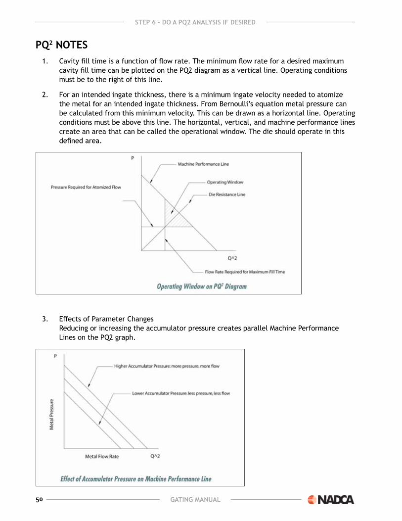
PQ2 notES1. Cavity fill time is a function of flow rate. the minimum flow rate for a desired maximum
cavity fill time can be plotted on the PQ2 diagram as a vertical line. operating conditions must be to the right of this line.
2. For an intended ingate thickness, there is a minimum ingate velocity needed to atomize the metal for an intended ingate thickness. From Bernoulli’s equation metal pressure can be calculated from this minimum velocity. this can be drawn as a horizontal line. operating conditions must be above this line. The horizontal, vertical, and machine performance lines create an area that can be called the operational window. The die should operate in this defined area.
3. effects of Parameter Changes Reducing or increasing the accumulator pressure creates parallel machine Performance lines on the PQ2 graph.

51GatinG Manual
StEP 6 – do a PQ2 analySiS if dESirEd
Closing the shot valve has the effect of creating machine Performance lines that pivot from the metal pressure point with zero flow. this data can come from the machine’s book or be determined experimentally.
Changing the plunger tip has the effect of changing the slope of the machine Performance line. smaller plungers yield higher metal pressure and less flow. larger plungers yield lower metal pressure and more flow.
Changing the ingate area changes the slope of the Die Resistance line. smaller ingate areas yield more pressure, less flow. larger ingates areas yield less pressure, more flow.

52 GatinG Manual
StEP 6 – do a PQ2 analySiS if dESirEd
From all these options many machine Performance and Die Resistance lines can be drawn to show the operating conditions for a given set of gating parameters. many scenarios are run. the objective is to find a combination of ingate area, ingate velocity, ingate thickness, plunger tip diameter, and accumulator pressure that create a large central operational window on the PQ2 diagram. NADCA provides software to help with the PQ2 analysis and calculations.
the PQ2 analysis can be run as a check on the conventional gating analysis or vice versa. Note the coefficient of discharge appears as a squared term in Bernoulli’s equation which means a small per cent change in this number results in a significant per cent metal pressure change all other factor being equal. the machine’s performance and other mechanical issues such as the alignment of the sleeve and plunger change through time. these factors affect the coefficient of discharge. selecting a coefficient of discharge on the low side is a conservative approach.

53GatinG Manual
StEP 7 – dESiGn thE fan and tanGEntial runnErS7
flow arEa conSidErationSthe function of the runner is to deliver the metal to the ingate and to generate the desired flow
pattern within the cavity segments. There are three runners used plus the chisel runner that is sometimes used in dealing with local porosity. The three runners are the straight fan, the curved fan, and the tangential runner.
the ingate controls the metal flow into the cavity. therefore, the ingate has the smallest area in the metal flow path from the biscuit or sprue to the cavity. If this were not true, then some other feature in the runner system will control the metal flow such as an undersized runner or an undersized nozzle on a hot chamber machine.
Runner systems should always be designed starting at the ingate and working back to the sprue or biscuit and in the case of hot chamber machines working back to the gooseneck plunger. At this point in the analysis the ingate areas and locations are known so the runner design starts at the gate opening and works backwards to the sprue or biscuit.
The runner area should decrease as the runner transitions into the gate. This not only maintains the gate as the smallest area in the flow path, but it also forces the metal flow to spread the full width of the gate and lets the gate do what it was designed to do. Decreasing the runner area leading up to the ingate also prevents mixing air with the metal in the runner that might show up in the casting as porosity.
starting at the gate, the runner will be larger than the gate. the ratio of the runner to gate area will vary with the design, and will usually range between 1.1:1 and 1.4:1. However, it can be larger as in the case of small castings where using a ratio of 1.4:1 would result in too much metal heat loss in the fan or tangential runner system. Thus, if the gate area is 1.00 in2, then the runner area should be between 1.1 and 1.4 square inches except in small castings.
The ratio is determined by several design factors, and it important to realize that there isn’t a magic number that applies to all circumstances. some of the factors to consider are:
aluMinuMtypical ratios will be about 1.1 to 1.4. the higher ratios are used where there is a larger flow
angle. A flow angle greater than 35° for a fan gate design will require a ratio of 1.3:1 or greater. A flow angle of 10° to 35° would be acceptable with a gate to runner ratio of about 1.1:1 to 1.3:1. Higher flow angles require more restriction to force the metal to conform to the gate shape.
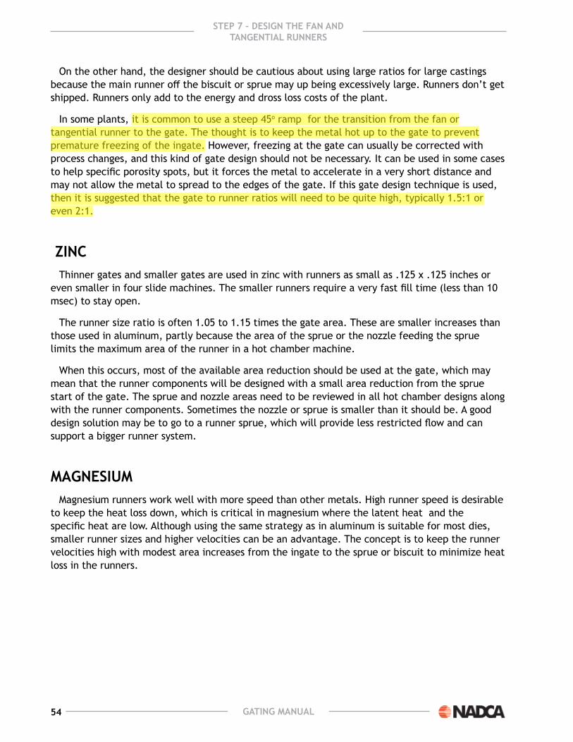
54 GatinG Manual
StEP 7 – dESiGn thE fan and tanGEntial runnErS
on the other hand, the designer should be cautious about using large ratios for large castings because the main runner off the biscuit or sprue may up being excessively large. Runners don’t get shipped. Runners only add to the energy and dross loss costs of the plant.
In some plants, it is common to use a steep 45o ramp for the transition from the fan or tangential runner to the gate. The thought is to keep the metal hot up to the gate to prevent premature freezing of the ingate. However, freezing at the gate can usually be corrected with process changes, and this kind of gate design should not be necessary. It can be used in some cases to help specific porosity spots, but it forces the metal to accelerate in a very short distance and may not allow the metal to spread to the edges of the gate. If this gate design technique is used, then it is suggested that the gate to runner ratios will need to be quite high, typically 1.5:1 or even 2:1.
Zincthinner gates and smaller gates are used in zinc with runners as small as .125 x .125 inches or
even smaller in four slide machines. the smaller runners require a very fast fill time (less than 10 msec) to stay open.
the runner size ratio is often 1.05 to 1.15 times the gate area. these are smaller increases than those used in aluminum, partly because the area of the sprue or the nozzle feeding the sprue limits the maximum area of the runner in a hot chamber machine.
when this occurs, most of the available area reduction should be used at the gate, which may mean that the runner components will be designed with a small area reduction from the sprue start of the gate. The sprue and nozzle areas need to be reviewed in all hot chamber designs along with the runner components. sometimes the nozzle or sprue is smaller than it should be. A good design solution may be to go to a runner sprue, which will provide less restricted flow and can support a bigger runner system.
MaGnESiuMmagnesium runners work well with more speed than other metals. High runner speed is desirable
to keep the heat loss down, which is critical in magnesium where the latent heat and the specific heat are low. Although using the same strategy as in aluminum is suitable for most dies, smaller runner sizes and higher velocities can be an advantage. The concept is to keep the runner velocities high with modest area increases from the ingate to the sprue or biscuit to minimize heat loss in the runners.

55GatinG Manual
StEP 7 – dESiGn thE fan and tanGEntial runnErS
fan runnErSFan runners can be used to feed the entire casting or to split the metal from a main runner
to two adjacent tangential runners. Fans generate a desirable strong center fill. there are two types of fans – a curved sided fan and a straight sided fan. In order for the fan to have constantly decreasing area from the main runner to the ingate, a curve sided fan’s depth will decrease linearly, and a straight sided fan will have a depth which is curved. If the fan is constructed with straight sides and a linear depth reduction, then the fan area from the runner to the ingate will not decrease linearly though the fan. The metal will pull away from the sidewall and generate a pocket. this pocket will feed a steam of air bubbles into the flowing metal and contribute to casting porosity.
straight and curve sided fans are shown in the next figures.

56 GatinG Manual
StEP 7 – dESiGn thE fan and tanGEntial runnErS
An inferior fan gate with straight sides and depth looks like the following.
the flat fan shape is simple to make and may appear to do reasonably well, but it will add gas porosity to the casting.
the advantages of straight sided fans are that the flow angle is known and the runner breaks clean without a trim die. the disadvantage of a straight fan is it is more difficult to machine into the die. The fan should be modeled and edm’ed in.
The advantage of a curve sided fan is that is easier to machine into the die. The disadvantages of the curve sided fan is the flow angle is not clearly defined and that the fan does not break cleanly and must be trimmed.
fan flow anGlESthe flow angle for the straight sided fan is the angle of the sidewall to the centerline. the
straight sided fan design shown earlier has a flow angle of 26°, which is measured as shown below. the curved fan gate has a flow angle measured at a point ¼ the distance from the gate to the runner, as shown below.

57GatinG Manual
StEP 7 – dESiGn thE fan and tanGEntial runnErS
the maximum flow angle for any fan is 45°. the flow off the ends of fans with flow angles greater than 45° will be negligible.
the edge of a curved fan tends to break out as shown below. If the part is hand degated or tumbled off, it is recommended that the gate width be reduced approximately as shown with the red dotted lines to address the break out issue.

58 GatinG Manual
StEP 7 – dESiGn thE fan and tanGEntial runnErS
the flow angle for fans varies from left to center to right. the average fan flow angle used to calculate the actual ingate area from the apparent ingate area is:
θ = ((θl + θr) / 4) + θc
where,
θ = average fan flow angle
θl = flow angle left side of fan
θr = flow angle right side of fan
θc = flow angle center of fan
dESiGninG fan runnErSThe procedure for designing a fan is:
1. Determine the fan width and the fan length. the fan width at section A is the same width as the ingate. The fan length is the distance from the end of the fan to the beginning of the fan, section I, joining the main runner. the ratio of the fan width to the fan length determines the fan’s flow angle at each edge. Increasing the fan length decreases the flow angle at the fan’s edges.
2. Divide the fan into equal sections from beginning to end. A convenient number of sections to use is 9.

59GatinG Manual
StEP 7 – dESiGn thE fan and tanGEntial runnErS
3. Determine the area of the end section A. this area is equal to or greater than the ingate area. It is customary to make the area of section A 10% greater than the ingate area it feeds. This gives some wiggle room if the ingates need to be increased slightly when the part is cast without having to reburn the fan to enlarge it.
4. Determine the area increase from section A to the beginning of the fan section I. In the example the area increases 200%. this percent increase is a judgement call and will vary with each casting. on one hand the objective is to deliver hot metal to the ingates, and on the other hand the objective is to minimize the size of the runners to reduce remelt costs.
5. Determine the area of each section with a linear reduction in area from the beginning of the fan to end of the fan. If 9 sections are used, then the area of section e is the average of sections A and I. the area of sections C is the average of sections A and e, etc.
6. Determine dimensions of the beginning of the fan, section I. the main runner dimensions that feeds the fan and the dimensions of section I are the same.
7. For a curve sided fan, the fan depth linearly decreases from the beginning to the end. Determine the depths of each section with a linear reduction from the beginning to the end. The same method as in Step 5 can be used.
8. Calculate the average width of each section. this is the section area divided by the section depth.
9. Put all the fan data into a chart and draw a sketch showing the plan view and the cross-sectional view of the fan. on the cross-sectional view show the relationship of the fan in the ejector half and the ingate in the cover half overlapping the fan and the land distance.
The straight sided fan is done the same way only the width increases linearly from the fan beginning to end. The fan depth is calculated from the sectional fan areas and widths and will be non-linear.
fan notES

60 GatinG Manual
StEP 7 – dESiGn thE fan and tanGEntial runnErS
Curved sided Fan Data table
ingate width = 5.000, ingate Thickness = .063, Flow angle = 40 degrees
section Distance Area Depth (h) Avg width Base (b) Top (t) side (c) side (d)A 0.000 0.347 0.069 5.000 5.012 4.988 0.012 0.012B 0.750 0.408 0.136 3.009 3.033 2.986 0.024 0.024C 1.500 0.470 0.202 2.326 2.362 2.291 0.036 0.036D 2.250 0.532 0.268 1.981 2.028 1.934 0.047 0.047e 3.000 0.593 0.335 1.773 1.832 1.714 0.059 0.059F 3.750 0.655 0.401 1.633 1.704 1.563 0.071 0.071g 4.500 0.717 0.467 1.533 1.616 1.451 0.082 0.082H 5.250 0.778 0.534 1.458 1.552 1.365 0.094 0.094I 6.000 0.840 0.600 1.400 1.506 1.294 0.106 0.106h = Area / depthAvg width = Area / hb = Avg width + ct = Avg width - cc = 0.176 * hd = 0.176 * hArea Ratio sections I:A 2.42
1. The sides of fans have 10o draft. Any section of the fan is actually a trapezoid.
2. Planned flow with associated flow angles was determined in step 2. By changing the fan length relative to the fan width, the flow angle changes. Normally many fan scenarios are generated to get the flow angle desired and to fit the fan to the space available on the die. It is helpful to have spreadsheets containing generic straight and curve sided fans so that fan design data can be calculated quickly and accurately.
either type can be set at an angle to direct the flow towards a problem area. the illustration below shows how this can be done. the figure below also shows the straight fan gate at left turned at a 30° angle. the arrows approximate the new flow pattern. this allows the flow to be directed at a particular problem area.

61GatinG Manual
StEP 7 – dESiGn thE fan and tanGEntial runnErS
flow PattErnS for thE fan GatESthe flow patterns generated by the two different types of fan gates are shown by the following
pictures:

62 GatinG Manual
StEP 7 – dESiGn thE fan and tanGEntial runnErS
tanGEntial runnErSTangential runners run tangent along the side of the cavity. The advantages of tangential runners
are:
● the runner is compact and can be kept close to the casting,
● the flow direction can be controlled, and
● hot metal can be distributed over a relatively long distance.
A disadvantage of tangential runners is that runners will get overly big if small flow angles are desired.
the tangential runner flow angle is determined by the ratio of ingate area to runner area. At any point in the tangential runner the flow angle is the arctangent of the gate area divided by the tangential runner area. For this calculation, the gate area is the total gate area downstream from the section selected, and the runner area is measured at the section selected.
Because of the flow angle, the metal sees a smaller gate area than that actually cut into the die. It also means the actual velocity is higher than the apparent ingate velocity.
actual gate area = Apparent gate area / Cosine (flow angle)
or
apparent gate area = actual gate area * Cosine (flow angle)
and, actual gate velocity = apparent gate velocity / cosine (flow angle)
where the Apparent gate velocity is calculated by using the plunger diameter, fast shot velocity, and measurements of the ingate.

63GatinG Manual
StEP 7 – dESiGn thE fan and tanGEntial runnErS
since the cosine of the flow angle is always less than one, the difference of the Actual and Apparent ingate velocities can be significant. solder and erosion problems can occur due to unexpected high actual ingate velocities especially with aluminum.
the following table shows the approximate flow angles attainable from the tangential runner. Note that a very large runner is needed to get the metal with a low flow angle into the casting. If this is the flow pattern that is needed, then a fan gate may be more appropriate than the tangential gate.
Examples of ratio of Gate/runner
Flow angel degreesrunner area Gate area
0.10 0.10 1.00 45.000.11 0.10 0.90 41.990.13 0.10 0.80 38.660.14 0.10 0.70 34.990.17 0.10 0.60 30.960.20 0.10 0.50 26.570.25 0.10 0.40 21.800.33 0.10 0.30 16.700.50 0.10 0.20 11.31
Practical tangential flow angles vary from 26° to 45°. A shock absorber is desirable for tangential runners. The shock absorber will prevent spitting of metal into the die at the end of the tangential runner when the runner is filling. this spurt of metal will eventually erode the runner and the ingate at the end of the runner. The shock absorber allows the tangential runner to fill and pressurize providing simultaneous fill along the tangential runner’s length. A proper designed shock absorber will trap compressed air in the center. shock absorbers should be feed tangentially to create a whirlpool flow pattern with air trapped in the center. An ejector pin should always be placed underneath the shock absorber. If there is no ejector pin under the shock absorber, then the shock absorber will stick to the die. The diameter of the shock absorber should be large enough to create the air pocket in the center. The shock absorber diameter should be approximately the square root of the inlet area to the tangential runner.

64 GatinG Manual
StEP 7 – dESiGn thE fan and tanGEntial runnErS
The dimensions for the designed tangential runners are provided to the toolmaker of die designer with the above drawing, a data chart, and a generic tangential runner cross section.

65GatinG Manual
StEP 7 – dESiGn thE fan and tanGEntial runnErS
The aspect ratio is the ratio of the average width to the height of the tangential runner. A typical aspect ratio for tangential runners is 2:1. An aspect ratio of 1:1 would be more compact conserving heat. An aspect ratio of 3:1 would be more spread out and would dissipate more heat to the runner die steel.
To calculate the dimensional data for each section:
1. Calculate the areas for all sections except the last (section J). the tangential runner area for any section is the ingate area that it feeds divided by the cosine of the flow angle.
2. Calculate h, b, d, t, and c for each section except the last (section J). the formulas for a 2:1 aspect ratio are given in the example.
3. the tangential runner at section J feeds an ingate of zero. However, it is customary to make section J at least as thick as the ingate. If a shock absorber is used, it needs to be big enough to feed the shock.

66 GatinG Manual
StEP 7 – dESiGn thE fan and tanGEntial runnErS
Tangential runners do not have to be kept parallel to the edge of the casting with tangential gates. the ramp from the runner to the casting can be extended so this type of gate can feed an irregular edge. This is shown below.

67GatinG Manual
StEP 7 – dESiGn thE fan and tanGEntial runnErS
the ramps from the runner to the casting can be lengthened as needed to fit the casting contour. the ramps are usually sloped about 5° from the runner to the casting (or to the land if one is used).
A side view of the technique is shown below.
this technique can also be used to direct the flow of a tangential runner. the runner can be angled to make the flow pattern go in the direction desired.
The picture below shows a gate design where the tangential gate was shaped so as to direct the flow at particular problem areas. the flow pattern in this case worked well to solve some defect problems.

68 GatinG Manual
StEP 7 – dESiGn thE fan and tanGEntial runnErS
If it is desired to have a different angle, it is possible to angle the runner away from the casting in order to get the flow angle directed better. the gate can be added to the curved sections of the tangential gate and thus obtain some different flow angles that could not be achieved with a straight section. This is shown below, where the runner curves were used to direct metal into the two corners of the casting that could not be reached without using this technique.
this technique is very powerful, especially when a good surface finish is required. this example was done by computer, but to do it manually, the following procedure will get a close approximation. First, set the straight section in the middle.

69GatinG Manual
StEP 7 – dESiGn thE fan and tanGEntial runnErS
now do the following steps:
1. Draw the flow vector as it is desired,
2. Add a perpendicular to the line approximately in the area the runner is expected to be.
3. then add a line at an angle to the line from step 2 of approximately 30°. the end of this line should intersect the edge casting where the initial gate starts. The runner will then be a curve matching the existing runner that is tangent to this line.
4. Draw a perpendicular to this line done in step 3, starting where the line from step 3 and the flow vector intersect.
5. Draw a vertical line from the starting point of the gate for the initial straight section.
6. where the lines from 4 and 5 intersect is the center of the radius forming the outside of the new runner section.
the 30° is selected as a flow angle that is relatively easy to achieve, this could be any value with in the range of about 30° to 40°. this curve would be the path for the runner that would flow in the direction of the vector – if the runner were sized to provide the flow angle selected when drawing the tangent line.
Main runnErS and cavity layoutmain runners carry the metal from the sprue or biscuit to fan and tangential runners. the runner is
usually done in trapezoidal shape, although round runners are used for miniature zinc 4-slide machines. Round runners should have a straight section added at the parting line to avoid a slight undercut.
The width to depth ratio is called the aspect ratio, and will usually be between 1:1 and 3:1. The lowest surface area to volume ratio comes when the when the depth is equal to the width, and this is typically used for most runners. However, in large aluminum dies where the main runner will get too large to freeze in a reasonable time, the runner depth is kept constant at about .7 inches and the width is expanded as necessary to get the required area.

70 GatinG Manual
StEP 7 – dESiGn thE fan and tanGEntial runnErS
the most important concept in runner design is that the beginning of flow at the biscuit or sprue must be the largest area, and that the metal encounters an ever decreasing area as it moves to the fan and tangential runners. ultimately, the smallest area in the delivery system is the ingate area and this area controls the flow and velocity going into the cavity not some other feature of the runner system.
Another factor to consider is the high velocity and momentum of the metal in the runner system. wherever the metal encounters sharp corners turbulence can be created causing gas entrapment, which ends up as porosity or blisters. Thus, main runners turns should be smooth and gradual.
Runners don’t get shipped. energy costs keep rising. excessively large runners slow the cycle time and increase energy costs. Therefore, the designer is encouraged to design the runner wisely.
runnEr dESiGn ProcEdurERunner design should start at the gate and proceed to the sleeve or sprue. the first step was
covered earlier in the fan and tangential runner design, and should result in the initial runner size about 1.1 to 1.3 times the gate area. The main runners should be increased in size as the design proceeds from the fan and tangential runners to the sprue or biscuit. each turn of transition from one main runner to two should have an area reduction from entrance to exit. Properly designed bends need only a small increase, usually 3% to about 5%, depending on the sharpness of the bend.
These small increases depend on having a good runner design, and a smooth model of the runner system, preferably one that can be machined from a CAD model.
“ y” junctions should also have an increase in area when going upstream from the branches from the main runner on the order of 3% to 10%. An increase of 5% for good smooth shapes should be adequate.
larger increases are more conservative and more certain to cover errors, however, they often result in a large main runner that slows the cycle time.
Tree runners are often used for multi cavity work. They are always a problem because the metal will not arrive at the top and bottom cavities at the same time. Tree runners violate the principle of simultaneous fill and should be avoided, as the top and bottom cavities will not run the same creating quality problems. It is far better to use a die layout with cavities equidistant from the sprue or biscuit.

71GatinG Manual
StEP 7 – dESiGn thE fan and tanGEntial runnErS
six cavity dies are more difficult, and may require some ingenuity, but the effort is well worth it.

72 GatinG Manual
StEP 7 – dESiGn thE fan and tanGEntial runnErS
The design of main runners follows the same pattern as with fan and tangential runners. The cross sections of all main runners need to be defined for the tool maker or the too designer. the aspect ratio of main runners is the ratio of the average width to the depth. Typical ratios are 1:1 to 3:1. Here is a spreadsheet example of main Runner dimensional data. the whole runner system is drawn on the preliminary die where the main runner sections are identified.

73GatinG Manual
StEP 7 – dESiGn thE fan and tanGEntial runnErS
Main runner descriptioncomponent description
1 Tangential2 Fan3 Fan4 Fan5 Fan6 Fan7 Fan
main Runner: Aspect Ratio = 2:1 Draft = 10o
Main runner Section
feeding area (in2)
avg width (in)
h (in) b (in) d (in) t (in) c (in)
e 1 0.237 0.688 0.344 0.748 0.061 0.627 0.061I Any Fan 0.225 0.671 0.335 0.730 0.059 0.612 0.059F 1+2 0.485 0.984 0.492 1.071 0.087 0.898 0.087g 1+2+3 0.721 1.201 0.600 1.306 0.106 1.095 0.106l 7 0.236 0.687 0.344 0.748 0.060 0.627 0.060k 6+7 0.473 0.972 0.486 1.058 0.086 0.887 0.086m All 1.643 1.813 0.906 1.972 0.160 1.653 0.160
(Area section m = All = k + 2*I + g =1.643 )
main Runner dimension formulas for an aspect ratio of 2:1
h = (Area / 2).5
b = 2.176 * h
d = 0.176 * h
t = 1.824 * h
c = 0.176 * h

74 GatinG Manual

75GatinG Manual
8 StEP 8 – dESiGn thE ovErflowS and vEntS
ovErflowS and outGatESoverflows collect the initial contaminated metal that traverses the cavity, provide local heat
to the far side of the cavity, and provide a base to help eject the casting off the die. the number and size of overflows is a function of the flow distance through the cavity whereas long distances will have more overflows and the surface finish requirements of the casting whereas good surface quality will have more overflows than a commercial finish. A guide to overflow size as a percent of the adjacent segment can be found in the table below:
typical overflow sizes
thickness of Segment - in.
(mm)
cavity fill time - sec.
overflow size as percent of adjacent cavity segmenthardware Quality Surface finish - %
Some Cold Shut allowed - %
0.035 (0.90) 0.012 - 0.021 150 750.050 (1.30) 0.017 - 0.029 100 500.075 (1.80) 0.026 - 0.044 50 250.100 (2.50) 0.035 - 0.059 25 250.120 (3.20) 0.042 - 0.071 ---- ----Note: the values shown are typical values which may change for specific situations.
overflows that connect to vents should be located at the last portion of the segment to fill. If the overflow fills before the segment, then backfilling will occur causing poor fill and porosity. metal will be drawn to the outgates and overflows, so it is better to have many modest overflows than a few large ones for purposes of distributed flow within the casting. like runners, overflows do not get shipped, so the number and placement of overflows should be judicious.
the outgate connects the casting to the overflow. the sum total of all the outgate areas should be approximately one half the total ingate area since the outgates provide the passageway for air to escape through the vents. For aluminum the minimum outgate thickness should be .040 in. For magnesium and zinc the minimum thickness is .020 in for conventional die casting. overflows are normally located on the ejector half with an ejector pin underneath them. outgates like ingates are normally located in the cover half.
If possible the design of overflows as with vents should be for inefficient metal flow. the concern is keep the molten metal within the die at the end of the shot. If the die does not hold the metal, then the packing that occurs at the last instant of fill is diminished causing poor surface finish and porosity. Inefficiency is created when the outgate is offset from the vent forcing the metal to turn within the overflow.

76 GatinG Manual
StEP 8 – dESiGn thE ovErflowS and vEntS
overflow dimensional data along the locations need to be provided to the toolmaker or die designer on the preliminary die layout. the following is an example of an overflow.
vEntSVents are essential to die casting. Vents let the air out of the die throughout the shot. If this
doesn’t happen air and other gasses will be trapped within the cavity with the metal. The trapped gas will be in the form of smooth round bubbles that form gas porosity. These bubbles can be anywhere, but will be concentrated in the areas that were the last to fill or at the last points to solidify. It is difficult in die casting to vent all the air. However, there is a big difference in residual air and the resultant casting quality between no vents and proper vents. If the die is designed with insufficient vents, over time the air will find a way out. the die will flash, and some of the flash will stick to the die causing inserts to be crushed unevenly into the holder block or the holder block itself will be crushed around the perimeter of the cavity inserts causing continuous flash or “natural venting”. This all can be avoided by designing proper vents.

77GatinG Manual
StEP 8 – dESiGn thE ovErflowS and vEntS
the best locations for the vents are the last points to fill. the simulation programs best predict these points. A program distributed by NADCA called CastView will do a good job of predicting these last to fill locations.
Air is compressible and reaches a terminal velocity in the vents no matter how much pressure is applied to the air. The air velocity in the vents assuming the terminal velocity is not reached is a function of the ingate velocity of the metal and the vent area. The air velocity in the vents is directly proportional to the ingate metal velocity and inversely proportional to the vent area. A way to determine the vent area is to calculate the incoming metal flow rate, and set the vent area so the volume of air that can escape through the vents must do so without exceeding a speed that is 70% of the speed of sound at standard conditions. to calculate this vent area, the metal flow rate (“Q”) is calculated first, and then it is assumed that the air escaping has the same flow rate. If the maximum reasonable velocity in the vents is assumed to be about 70% of the speed of sound or 8000 in/sec (200 m/s), then the approximate minimum area for the vents can be found from:
Minimum vent area = Q / 8000
Depending on the choice of variables, this calculation approximates the formula developed by J. F. wallace:
aV = (0.00571)(V)/(T)(k)
where:
AV = the minimum area of the vent
V = the total volume of gas in the system, including runner and shot sleeve
t = the cavity fill time
k = the percentage of the vent area remaining open during filling
It would be reasonable to assume the air in the shot sleeve is moved out under slow speed conditions, and so is not a factor during cavity filling. If this is the case, we could let V = cavity and runner volume only, and assume the percentage of vents remaining open is about 50%; then the two formulas will be about the same.
Another way to determine the vent area is to divide the ingate area by four or:
vent area = ingate area / 4
since the normal range of ingate velocities is less than 2000 in/sec, this formula can also be used.
the problem in designing a venting system with the proper area is finding real estate on the die to put all the vents in. It is always a good idea to have a plan for the vents before signing off on the cavity insert sizes. sometimes the steel is ordered and there isn’t enough room to install the vents. this issue also becomes complicated with slides and other features that make it difficult or impossible to install the proper venting. If the casting is sensitive to gas porosity, then this should be a strong warning that there will be some gas porosity in the casting, or that freeze blocks or vacuum should be considered. on the other hand, if the casting is not machined, and gas porosity is not an issue, then probably the designer should add as much venting as possible and accept the remaining porosity. The following is an illustration of a freeze block. The freeze block allows for a large vent area in a small die area.
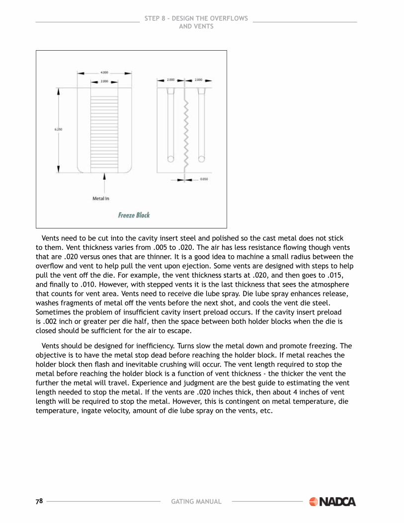
78 GatinG Manual
StEP 8 – dESiGn thE ovErflowS and vEntS
Vents need to be cut into the cavity insert steel and polished so the cast metal does not stick to them. Vent thickness varies from .005 to .020. the air has less resistance flowing though vents that are .020 versus ones that are thinner. It is a good idea to machine a small radius between the overflow and vent to help pull the vent upon ejection. some vents are designed with steps to help pull the vent off the die. For example, the vent thickness starts at .020, and then goes to .015, and finally to .010. However, with stepped vents it is the last thickness that sees the atmosphere that counts for vent area. Vents need to receive die lube spray. Die lube spray enhances release, washes fragments of metal off the vents before the next shot, and cools the vent die steel. sometimes the problem of insufficient cavity insert preload occurs. If the cavity insert preload is .002 inch or greater per die half, then the space between both holder blocks when the die is closed should be sufficient for the air to escape.
Vents should be designed for inefficiency. turns slow the metal down and promote freezing. the objective is to have the metal stop dead before reaching the holder block. If metal reaches the holder block then flash and inevitable crushing will occur. the vent length required to stop the metal before reaching the holder block is a function of vent thickness - the thicker the vent the further the metal will travel. experience and judgment are the best guide to estimating the vent length needed to stop the metal. If the vents are .020 inches thick, then about 4 inches of vent length will be required to stop the metal. However, this is contingent on metal temperature, die temperature, ingate velocity, amount of die lube spray on the vents, etc.

79GatinG Manual
StEP 8 – dESiGn thE ovErflowS and vEntS
A better system than vents to remove the air is to evacuate it during the shot with a vacuum system. Vacuum removes the air and also lowers the required shot pressure as the metal wants to fill the nooks and crannies of the cavity. However, vacuum has problems of its own as it another thing in the process that can go wrong such as when the vacuum valve fills with metal in the middle of a production run producing neither vacuum or venting. For gating design purposes, it is important that the proper effort be applied to finding the last point to fill to locate the vacuum channels. many vacuum runners look like the ingate runner system as vacuum is pulled from multiple locations and fed to main vacuum runner leading to be inefficient with turns and blind runners.
the vacuum channels need to be large enough with low resistance to handle the airflow during evacuation for the system to work properly. The time available for the vacuum system to work is less than 1 second. Although the pressure from the incoming metal will push some of the air out, the vacuum system should have evacuated most of the air before the metal arrives. The vacuum system suppliers are a good source for vacuum runner design information.
the vacuum valve pulls vacuum throughout the entire shot including fast shot. what triggers the valve to close is the metal itself reaching the valve. However, the valve is prone to failing as metal eventually gets into the valve. An alternative to this approach is to pull the vacuum though a freeze block or freeze blocks. In this case, a slow shot velocity of around 10 in/sec is used and the vacuum is shut off prior to going into fast shot. the vacuum levels achieved with this method will not be as good as with valves, but it is simpler and easier to maintain. The freeze block needs to be sprayed with air and die lube to prevent metal fragments from sticking and building up on the freeze block.

80 GatinG Manual

81GatinG Manual
StEP 9 – SiMulation9The use of simulation is certain to become more popular as computers become more
powerful and the capability of the simulation software gets better. simulation is a useful engineering tool, and should be used to supplement the engineering work of gating and not to replace it. In the described gating process in this book there are a lot of assumptions made by the designer and a lot of thought that is needed for any well designed gating system. simulation is not a substitute for the techniques described in this book and should be done after the gating design is complete Ideally, simulation should be done as early as possible so the results can so the results can influence
the part design. using simulation has several useful and important objectives that can assist making the gating design better:
1. what does the simulator say about the flow pattern? Is the flow pattern similar to one envisioned in step 2?
2. where are the last areas to fill? Are the outgates adjacent to these areas?
3. Are there areas of trapped gas critical to porosity control? Does the proposed design and pattern address them?
4. Does shrink porosity occur in areas critical to porosity control? Does the proposed ingate location and thickness address them?
5. Is there strong flow to areas where surface finish matters?
the last areas to fill is the easiest, and probably the most important of the factors located by the first simulation run. there may be several pockets of possible trapped gas where the gas has no escape path, and is surrounded by liquid metal at the end of fill. these locations could have gas porosity and perhaps poor fill..
A product of the NADCA research efforts is a program called CastView, which is designed to locate the last point to fill quickly. the program can run in minutes as opposed to the hours needed by full blown commercial simulation software. It also can be run by anyone, and does not need a trained simulation operator to use it.
the designer should determine if these last to fill points are at a location where overflows and vents can be relocated or added. If they are in areas where surface finish or porosity matters, then possibly flow patterns with revised ingate locations can be changed and another simulation done.
If there are areas critical to surface finish requirements, then the area should be checked for smooth flow conditions, for a very minimum amount of swirls, and particularly for any indication of early metal flow mixing with late metal flow on the surface.

82 GatinG Manual
StEP 9 – SiMulation
If there is an area of concern about gas porosity, then the user should check for swirls or trapped gas pockets in this area. there should be smooth metal flow through this area, and the pockets should be in other locations. If the software is capable, this should include examining the internal flow inside the casting.
the flow simulations may need to be changed and repeated several times for different gating and process conditions to get the optimum gating situation. This will be similar to the same trial and error method that used to be done on the die casting machine. However, it is just a lot cheaper and faster on the computer. The information learned from simulation can be valuable, but the user needs make sure the results are interpreted properly by someone familiar with die casting and not just familiar with simulation.
If there is concern about shrink porosity, then an initial thermal analysis should be run. the thermal analysis will be needed for oil and water cooling channel placement and can predict the cold areas and the hot areas that may affect surface finish or shrink porosity. most systems at this time can not predict the results of applying intensified pressure during solidification as they were designed for other casting processes not pressure casting. the user should have some experience in die casting to interpret the results and be somewhat cautious with the simulator’s results.
since simulators will predict the cold and the hot locations, this information can be effective in placing water or hot oil lines. Die lube spray also removes heat but not all systems can account for the effects of the spray. many interations of the thermal simulation are done where the cooling channels are moved, resized, and the coolant changed in order to optimize the design.
once the gating system and the heating/cooling systems are optimized, then the die design can be finalized and given to the die designer of tool maker so construction can start.
Computer are getting faster and software is getting cheaper and better. the days are coming where simulation will be the standard method of verifying and optimizing gating designs.
rEfErEncES1. e.A. Herman, J. F. wallace, “Copper Alloy Pressure Die Casting”, International Copper
Research Association, 1975
2. e. A. Herman, “gating Die Casting Dies”, society of Die Casting engineers, 1979
3. e. A. Herman, “Die Casting Dies, Designing”, society of Die Casting engineers, 1979
4. J. A. wallace, “Practical Application and the Results of metal Flow and gating Research”, , 1965
5. Russ Van Rens ,“gating Design”, NADCA, 1996
6. w. walkington, “seven steps to Quality gating Design”, NADCA, 2001
7. Derek Cocks, “Fan and tangent gate Feed Design system” , American Die Casting Institute, 1987

83GatinG Manual
StEP 9 – SiMulation