Embed Size (px)
Citation preview
P. 1 of 12
p/n: IM-9PH20S30 Rev. R, 5/18/2015
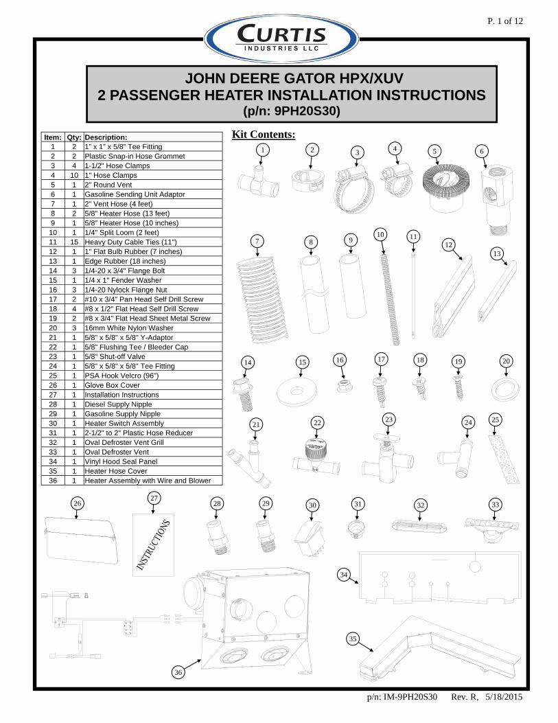
JOHN DEERE GATOR HPX/XUV 2 PASSENGER HEATER INSTALLATION INSTRUCTIONS
(p/n: 9PH20S30)
Kit Contents:
11
14 16 20
36
34
1 2 3 4 5 6
7 8 9 10
15
13 12
17 18 19
21 22 23 24
26 27
28 29 30 31 32 33
35
25
Item: Qty: Description: 1 2 1” x 1” x 5/8” Tee Fitting 2 2 Plastic Snap-in Hose Grommet 3 4 1-1/2" Hose Clamps 4 10 1" Hose Clamps 5 1 2" Round Vent 6 1 Gasoline Sending Unit Adaptor 7 1 2" Vent Hose (4 feet) 8 2 5/8" Heater Hose (13 feet) 9 1 5/8" Heater Hose (10 inches)
10 1 1/4" Split Loom (2 feet) 11 15 Heavy Duty Cable Ties (11") 12 1 1" Flat Bulb Rubber (7 inches) 13 1 Edge Rubber (18 inches) 14 3 1/4-20 x 3/4" Flange Bolt 15 1 1/4 x 1" Fender Washer 16 3 1/4-20 Nylock Flange Nut 17 2 #10 x 3/4" Pan Head Self Drill Screw 18 4 #8 x 1/2" Flat Head Self Drill Screw 19 2 #8 x 3/4" Flat Head Sheet Metal Screw 20 3 16mm White Nylon Washer 21 1 5/8" x 5/8" x 5/8" Y-Adaptor 22 1 5/8" Flushing Tee / Bleeder Cap 23 1 5/8" Shut-off Valve 24 1 5/8" x 5/8" x 5/8" Tee Fitting 25 1 PSA Hook Velcro (96") 26 1 Glove Box Cover 27 1 Installation Instructions 28 1 Diesel Supply Nipple 29 1 Gasoline Supply Nipple 30 1 Heater Switch Assembly 31 1 2-1/2" to 2" Plastic Hose Reducer 32 1 Oval Defroster Vent Grill 33 1 Oval Defroster Vent 34 1 Vinyl Hood Seal Panel 35 1 Heater Hose Cover 36 1 Heater Assembly with Wire and Blower

P. 2 of 12
This manual is the property of the owner. Be sure to leave with the owner when installation is complete. Parking Safety 1. Stop machine on level surface 2. Set parking brake 3. Remove key 4. Wait for engine and all moving parts to stop before leaving
the vehicle. CAUTION: Avoid Injury! Touching hot surfaces can burn skin. The engine, components, and fluids will be hot if the engine has been running. Allow engine to completely cool before servicing or working near the engine or components. 1. Install Glove Box Cover
1.1 Remove the under hood storage compartment.
1.2 Remove and retain the (2) Phillips head screws on the inside of the glove box. The plastic push-in clip retainer securing the glove box to the fender can be discarded. Remove the glove box and retain the (2) clip nuts from the glove box. Install the clip nuts onto the dash board and install the supplied glove box cover using the Phillips head hardware from the glove box. (See Fig. 1.2) 2. Install Heater
2.1 Connect the 2” vent hose to the plastic outlet on the front face of the heater box and secure with a cable tie.
2.2 Move the heater into position and loosely bolt the bottom right bracket through the hole in the vehicle fender with the hardware listed below. (Note: the fender washer should be on the underside of the fender. Leave finger tight)
Qty Hardware 1 1/4-20 x 3/4” Flange Bolt 1 1/4 x 1” Steel Fender Washer 1 1/4-20 Flanged Locknut
2.3 Fasten the left bracket to the vehicle frame with the following hardware using the two holes as a guide. See Fig. 2.3
Qty Hardware 2 #10 x 3/4” Pan Head Self Drill Screw
2.4 Tighten the lower bolt installed in step 2.2 at this time.
FIGURE 1.2
FIGURE 2.3
(2) Screws
TOOLS REQUIRED: ANTIFREEZE TEFLON TAPE DRAIN PAN POWER VACUUM BLEEDER (RECOMMENDED) SNIPS OR KNIFE TO CUT HOSE AND WIRE TIES REGULAR SCREWDRIVER OR NUT DRIVER FOR HOSE CLAMPS NUMBER 2 PHILLIPS DRIVER
SCREW GUN STANDARD & METRIC WRENCHES, STANDARD & METRIC SOCKETS RATCHET DRILL 2-1/16” HOLE SAW OR 2” HOLE SAW & DREMEL TOOL 7/8” HOLE SAW SAW TO CUT PLASTIC STORAGE
P. 3 of 12
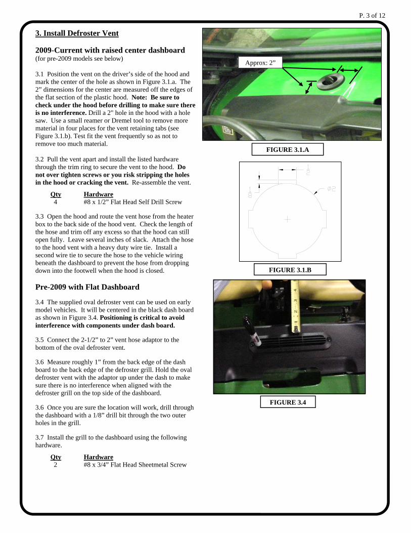
3. Install Defroster Vent 2009-Current with raised center dashboard (for pre-2009 models see below) 3.1 Position the vent on the driver’s side of the hood and mark the center of the hole as shown in Figure 3.1.a. The 2” dimensions for the center are measured off the edges of the flat section of the plastic hood. Note: Be sure to check under the hood before drilling to make sure there is no interference. Drill a 2" hole in the hood with a hole saw. Use a small reamer or Dremel tool to remove more material in four places for the vent retaining tabs (see Figure 3.1.b). Test fit the vent frequently so as not to remove too much material. 3.2 Pull the vent apart and install the listed hardware through the trim ring to secure the vent to the hood. Do not over tighten screws or you risk stripping the holes in the hood or cracking the vent. Re-assemble the vent.
Qty Hardware 4 #8 x 1/2” Flat Head Self Drill Screw
3.3 Open the hood and route the vent hose from the heater box to the back side of the hood vent. Check the length of the hose and trim off any excess so that the hood can still open fully. Leave several inches of slack. Attach the hose to the hood vent with a heavy duty wire tie. Install a second wire tie to secure the hose to the vehicle wiring beneath the dashboard to prevent the hose from dropping down into the footwell when the hood is closed. Pre-2009 with Flat Dashboard
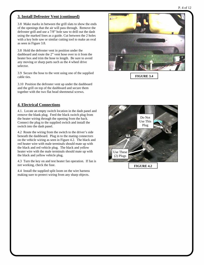
3.4 The supplied oval defroster vent can be used on early model vehicles. It will be centered in the black dash board as shown in Figure 3.4. Positioning is critical to avoid interference with components under dash board.
3.5 Connect the 2-1/2” to 2” vent hose adaptor to the bottom of the oval defroster vent.
3.6 Measure roughly 1” from the back edge of the dash board to the back edge of the defroster grill. Hold the oval defroster vent with the adaptor up under the dash to make sure there is no interference when aligned with the defroster grill on the top side of the dashboard.
3.6 Once you are sure the location will work, drill through the dashboard with a 1/8” drill bit through the two outer holes in the grill.
3.7 Install the grill to the dashboard using the following hardware.
Qty Hardware 2 #8 x 3/4” Flat Head Sheetmetal Screw
FIGURE 3.1.A
FIGURE 3.4
FIGURE 3.1.B
Approx: 2”
P. 4 of 12
Use These (2) Plugs
Do Not Use This
Plug
FIGURE 4.2
3. Install Defroster Vent (continued)
3.8 Make marks in between the grill slats to show the ends of the openings that the air will pass through. Remove the defroster grill and use a 7/8” hole saw to drill out the dash using the marked lines as a guide. Cut between the 2 holes with a key hole saw or similar cutting tool to make an oval as seen in Figure 3.8.
3.8 Hold the defroster vent in position under the dashboard and route the 2” vent hose over to it from the heater box and trim the hose to length. Be sure to avoid any moving or sharp parts such as the 4 wheel drive selector.
3.9 Secure the hose to the vent using one of the supplied cable ties.
3.10 Position the defroster vent up under the dashboard and the grill on top of the dashboard and secure them together with the two flat head sheetmetal screws.
4. Electrical Connections
4.1. Locate an empty switch location in the dash panel and remove the blank plug. Feed the black switch plug from the heater wiring through the opening from the back. Connect the plug to the supplied switch and install the switch into the dash panel.
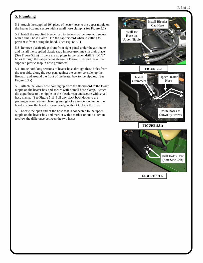
4.2 Route the wiring from the switch to the driver’s side beneath the dashboard. Plug in to the mating connectors on the vehicle wiring as seen in Figure 4.2. The black and red heater wire with male terminals should mate up with the black and red vehicle plug. The black and yellow heater wire with the male terminals should mate up with the black and yellow vehicle plug.
4.3 Turn the key on and test heater fan operation. If fan is not working, check the fuse.
4.4 Install the supplied split loom on the wire harness making sure to protect wiring from any sharp objects.
FIGURE 3.4
P. 5 of 12
5. Plumbing
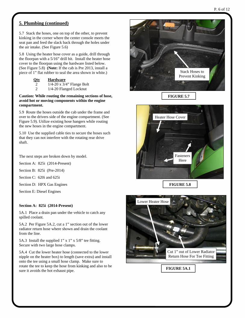
5.1 Attach the supplied 10” piece of heater hose to the upper nipple on the heater box and secure with a small hose clamp. (See Figure 5.1)
5.2 Install the supplied bleeder cap to the end of the hose and secure with a small hose clamp. Tip the cap forward when installing to prevent it from hitting the hood. (See Figure 5.1)
5.3 Remove plastic plugs from front right panel under the air intake and install the supplied plastic snap in hose grommets in their place. (See Figure 5.3.a) If there are no plugs in the panel, drill (2) 1-1/8” holes through the cab panel as shown in Figure 5.3.b and install the supplied plastic snap in hose grommets.
5.4 Route both long sections of heater hose through these holes from the rear side, along the seat pan, against the center console, up the firewall, and around the front of the heater box to the nipples. (See Figure 5.3.a)
5.5 Attach the lower hose coming up from the floorboard to the lower nipple on the heater box and secure with a small hose clamp. Attach the upper hose to the nipple on the bleeder cap and secure with small hose clamp. (See Figure 5.1) Pull any slack back down to the passenger compartment, leaving enough of a service loop under the hood to allow the hood to close easily, without kinking the hose.
5.6 Locate the open end of the hose that is connected to the upper nipple on the heater box and mark it with a marker or cut a notch in it to show the difference between the two hoses.
FIGURE 5.3.a
FIGURE 5.1
Install Grommets
Route hoses as shown by arrows
Upper Heater Hose
Install Bleeder Cap Here
Install 10” Hose on
Upper Nipple
FIGURE 5.3.b
Drill Holes Here (Soft Side Cab)
P. 6 of 12
5. Plumbing (continued)
5.7 Stack the hoses, one on top of the other, to prevent kinking in the corner where the center console meets the seat pan and feed the slack back through the holes under the air intake. (See Figure 5.6)
5.8 Using the heater hose cover as a guide, drill through the floorpan with a 5/16” drill bit. Install the heater hose cover to the floorpan using the hardware listed below. (See Figure 5.8) (Note: If the cab is Pre 2013, install a piece of 1” flat rubber to seal the area shown in white.)
Qty Hardware 2 1/4-20 x 3/4” Flange Bolt 2 1/4-20 Flanged Locknut
Caution: While routing the remaining sections of hose, avoid hot or moving components within the engine compartment.
5.9 Route the hoses outside the cab under the frame and over to the drivers side of the engine compartment. (See Figure 5.9). Utilize existing hose hangers while routing the new hoses in the engine compartment.
5.10 Use the supplied cable ties to secure the hoses such that they can not interfere with the rotating rear drive shaft.
The next steps are broken down by model.
Section A: 825i (2014-Present)
Section B: 825i (Pre-2014)
Section C: 620i and 625i
Section D: HPX Gas Engines
Section E: Diesel Engines
Section A: 825i (2014-Present)
5A.1 Place a drain pan under the vehicle to catch any spilled coolant.
5A.2 Per Figure 5A.2, cut a 1” section out of the lower radiator return hose where shown and drain the coolant from the line.
5A.3 Install the supplied 1” x 1” x 5/8” tee fitting. Secure with two large hose clamps.
5A.4 Cut the lower heater hose (connected to the lower nipple on the heater box) to length (save extra) and install onto the tee using a small hose clamp. Make sure to rotate the tee to keep the hose from kinking and also to be sure it avoids the hot exhaust pipe.
FIGURE 5.8
Fasteners Here
Heater Hose Cover
FIGURE 5.7
Stack Hoses to Prevent Kinking
FIGURE 5A.1
Cut 1” out of Lower Radiator Return Hose For Tee Fitting
Lower Heater Hose
P. 7 of 12
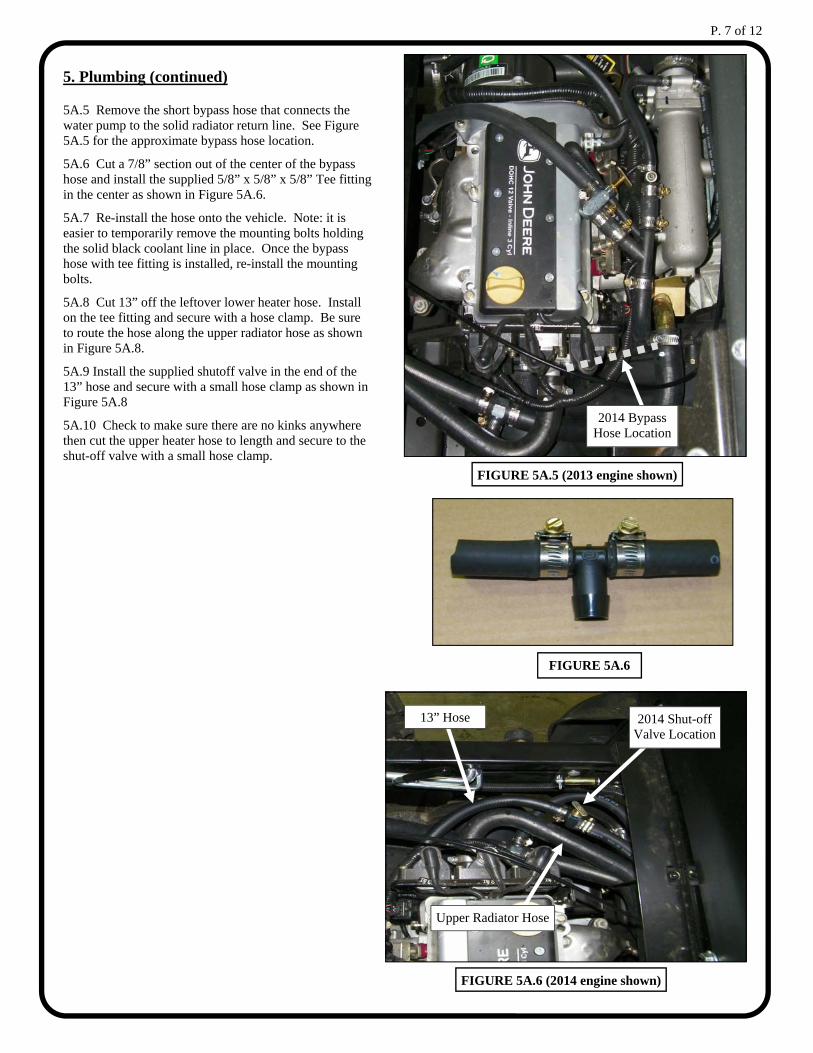
FIGURE 5A.6 (2014 engine shown)
2014 Shut-off Valve Location
Upper Radiator Hose
13” Hose
FIGURE 5A.6
FIGURE 5A.5 (2013 engine shown)
2014 Bypass Hose Location
5. Plumbing (continued)
5A.5 Remove the short bypass hose that connects the water pump to the solid radiator return line. See Figure 5A.5 for the approximate bypass hose location.
5A.6 Cut a 7/8” section out of the center of the bypass hose and install the supplied 5/8” x 5/8” x 5/8” Tee fitting in the center as shown in Figure 5A.6.
5A.7 Re-install the hose onto the vehicle. Note: it is easier to temporarily remove the mounting bolts holding the solid black coolant line in place. Once the bypass hose with tee fitting is installed, re-install the mounting bolts.
5A.8 Cut 13” off the leftover lower heater hose. Install on the tee fitting and secure with a hose clamp. Be sure to route the hose along the upper radiator hose as shown in Figure 5A.8.
5A.9 Install the supplied shutoff valve in the end of the 13” hose and secure with a small hose clamp as shown in Figure 5A.8
5A.10 Check to make sure there are no kinks anywhere then cut the upper heater hose to length and secure to the shut-off valve with a small hose clamp.
P. 8 of 12
5. Plumbing (continued)
Section B: 825i (Pre-2014)
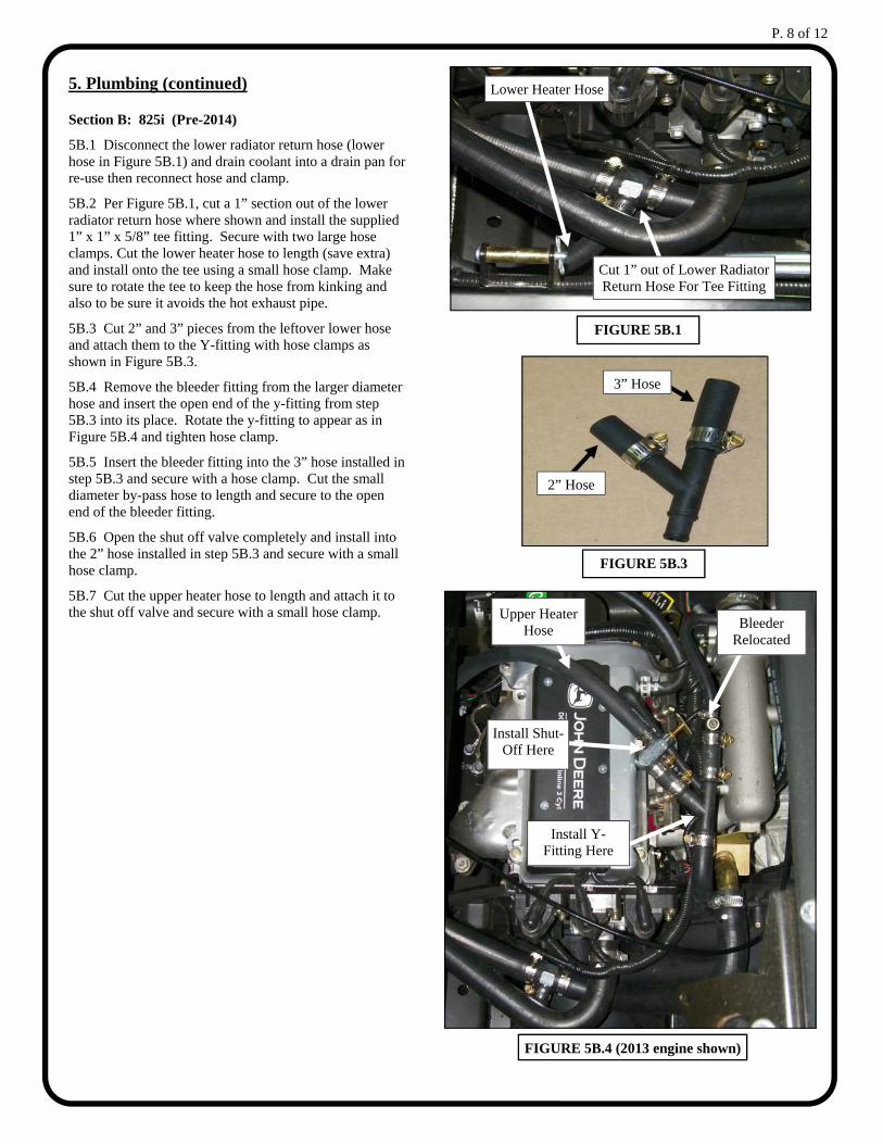
5B.1 Disconnect the lower radiator return hose (lower hose in Figure 5B.1) and drain coolant into a drain pan for re-use then reconnect hose and clamp.
5B.2 Per Figure 5B.1, cut a 1” section out of the lower radiator return hose where shown and install the supplied 1” x 1” x 5/8” tee fitting. Secure with two large hose clamps. Cut the lower heater hose to length (save extra) and install onto the tee using a small hose clamp. Make sure to rotate the tee to keep the hose from kinking and also to be sure it avoids the hot exhaust pipe.
5B.3 Cut 2” and 3” pieces from the leftover lower hose and attach them to the Y-fitting with hose clamps as shown in Figure 5B.3.
5B.4 Remove the bleeder fitting from the larger diameter hose and insert the open end of the y-fitting from step 5B.3 into its place. Rotate the y-fitting to appear as in Figure 5B.4 and tighten hose clamp.
5B.5 Insert the bleeder fitting into the 3” hose installed in step 5B.3 and secure with a hose clamp. Cut the small diameter by-pass hose to length and secure to the open end of the bleeder fitting.
5B.6 Open the shut off valve completely and install into the 2” hose installed in step 5B.3 and secure with a small hose clamp.
5B.7 Cut the upper heater hose to length and attach it to the shut off valve and secure with a small hose clamp.
3” Hose
2” Hose
FIGURE 5B.3
FIGURE 5B.1
Cut 1” out of Lower Radiator Return Hose For Tee Fitting
Lower Heater Hose
FIGURE 5B.4 (2013 engine shown)
Install Y-Fitting Here
Install Shut-Off Here
Bleeder Relocated
Upper Heater Hose
P. 9 of 12
5. Plumbing (continued)
Section C: 620i and 625i
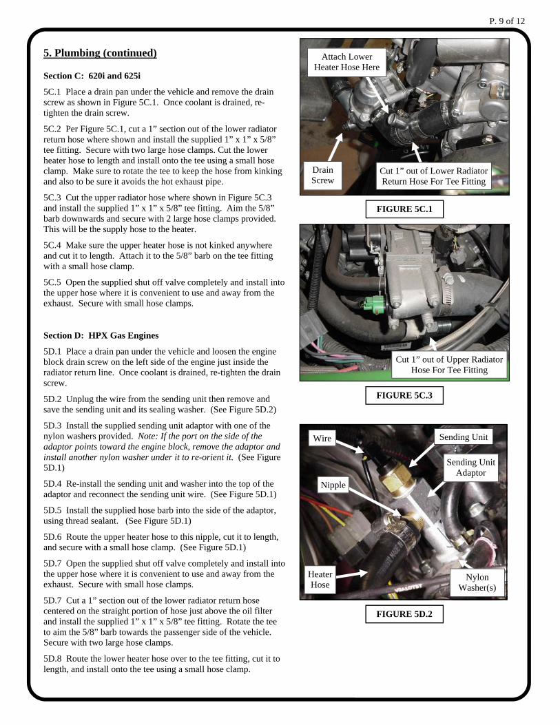
5C.1 Place a drain pan under the vehicle and remove the drain screw as shown in Figure 5C.1. Once coolant is drained, re-tighten the drain screw.
5C.2 Per Figure 5C.1, cut a 1” section out of the lower radiator return hose where shown and install the supplied 1” x 1” x 5/8” tee fitting. Secure with two large hose clamps. Cut the lower heater hose to length and install onto the tee using a small hose clamp. Make sure to rotate the tee to keep the hose from kinking and also to be sure it avoids the hot exhaust pipe.
5C.3 Cut the upper radiator hose where shown in Figure 5C.3 and install the supplied 1” x 1” x 5/8” tee fitting. Aim the 5/8” barb downwards and secure with 2 large hose clamps provided. This will be the supply hose to the heater.
5C.4 Make sure the upper heater hose is not kinked anywhere and cut it to length. Attach it to the 5/8” barb on the tee fitting with a small hose clamp.
5C.5 Open the supplied shut off valve completely and install into the upper hose where it is convenient to use and away from the exhaust. Secure with small hose clamps.
Section D: HPX Gas Engines
5D.1 Place a drain pan under the vehicle and loosen the engine block drain screw on the left side of the engine just inside the radiator return line. Once coolant is drained, re-tighten the drain screw.
5D.2 Unplug the wire from the sending unit then remove and save the sending unit and its sealing washer. (See Figure 5D.2)
5D.3 Install the supplied sending unit adaptor with one of the nylon washers provided. Note: If the port on the side of the adaptor points toward the engine block, remove the adaptor and install another nylon washer under it to re-orient it. (See Figure 5D.1)
5D.4 Re-install the sending unit and washer into the top of the adaptor and reconnect the sending unit wire. (See Figure 5D.1)
5D.5 Install the supplied hose barb into the side of the adaptor, using thread sealant. (See Figure 5D.1)
5D.6 Route the upper heater hose to this nipple, cut it to length, and secure with a small hose clamp. (See Figure 5D.1)
5D.7 Open the supplied shut off valve completely and install into the upper hose where it is convenient to use and away from the exhaust. Secure with small hose clamps.
5D.7 Cut a 1” section out of the lower radiator return hose centered on the straight portion of hose just above the oil filter and install the supplied 1” x 1” x 5/8” tee fitting. Rotate the tee to aim the 5/8” barb towards the passenger side of the vehicle. Secure with two large hose clamps.
5D.8 Route the lower heater hose over to the tee fitting, cut it to length, and install onto the tee using a small hose clamp.
FIGURE 5C.1
Cut 1” out of Lower Radiator Return Hose For Tee Fitting
Attach Lower Heater Hose Here
Cut 1” out of Upper Radiator Hose For Tee Fitting
FIGURE 5C.3
FIGURE 5D.2
Sending Unit
Sending Unit Adaptor
Nylon Washer(s)
Nipple
Heater Hose
Wire
Drain Screw
P. 10 of 12
5. Plumbing (continued)
Section E: Diesel Engines
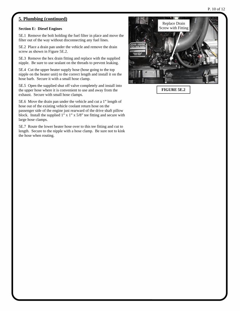
5E.1 Remove the bolt holding the fuel filter in place and move the filter out of the way without disconnecting any fuel lines.
5E.2 Place a drain pan under the vehicle and remove the drain screw as shown in Figure 5E.2.
5E.3 Remove the hex drain fitting and replace with the supplied nipple. Be sure to use sealant on the threads to prevent leaking.
5E.4 Cut the upper heater supply hose (hose going to the top nipple on the heater unit) to the correct length and install it on the hose barb. Secure it with a small hose clamp.
5E.5 Open the supplied shut off valve completely and install into the upper hose where it is convenient to use and away from the exhaust. Secure with small hose clamps.
5E.6 Move the drain pan under the vehicle and cut a 1” length of hose out of the existing vehicle coolant return hose on the passenger side of the engine just rearward of the drive shaft pillow block. Install the supplied 1” x 1” x 5/8” tee fitting and secure with large hose clamps.
5E.7 Route the lower heater hose over to this tee fitting and cut to length. Secure to the nipple with a hose clamp. Be sure not to kink the hose when routing.
FIGURE 5E.2
Replace Drain Screw with Fitting
P. 11 of 12
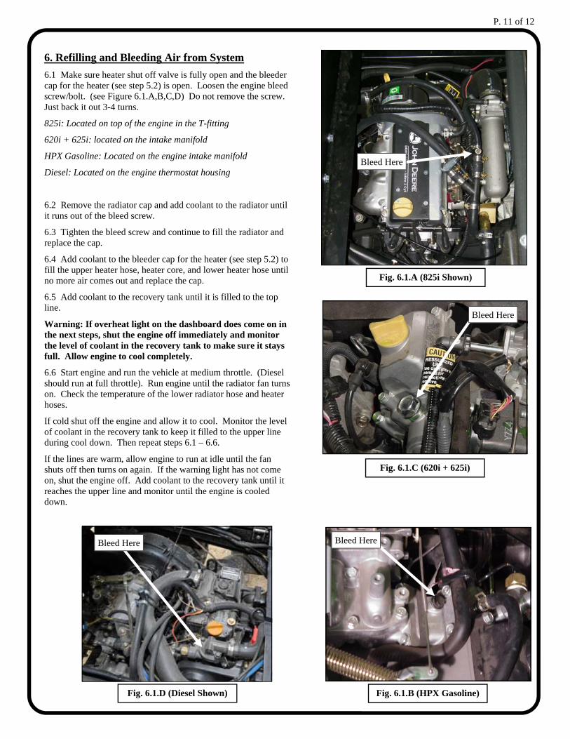
6. Refilling and Bleeding Air from System
6.1 Make sure heater shut off valve is fully open and the bleeder cap for the heater (see step 5.2) is open. Loosen the engine bleed screw/bolt. (see Figure 6.1.A,B,C,D) Do not remove the screw. Just back it out 3-4 turns.
825i: Located on top of the engine in the T-fitting
620i + 625i: located on the intake manifold
HPX Gasoline: Located on the engine intake manifold
Diesel: Located on the engine thermostat housing
6.2 Remove the radiator cap and add coolant to the radiator until it runs out of the bleed screw.
6.3 Tighten the bleed screw and continue to fill the radiator and replace the cap.
6.4 Add coolant to the bleeder cap for the heater (see step 5.2) to fill the upper heater hose, heater core, and lower heater hose until no more air comes out and replace the cap.
6.5 Add coolant to the recovery tank until it is filled to the top line.
Warning: If overheat light on the dashboard does come on in the next steps, shut the engine off immediately and monitor the level of coolant in the recovery tank to make sure it stays full. Allow engine to cool completely.
6.6 Start engine and run the vehicle at medium throttle. (Diesel should run at full throttle). Run engine until the radiator fan turns on. Check the temperature of the lower radiator hose and heater hoses.
If cold shut off the engine and allow it to cool. Monitor the level of coolant in the recovery tank to keep it filled to the upper line during cool down. Then repeat steps 6.1 – 6.6.
If the lines are warm, allow engine to run at idle until the fan shuts off then turns on again. If the warning light has not come on, shut the engine off. Add coolant to the recovery tank until it reaches the upper line and monitor until the engine is cooled down.
Fig. 6.1.A (825i Shown)
Bleed Here
Fig. 6.1.B (HPX Gasoline)
Bleed Here
Bleed Here
Fig. 6.1.C (620i + 625i)
Fig. 6.1.D (Diesel Shown)
Bleed Here
P. 12 of 12
6. Refilling and Bleeding Air from System (cont.)
The cooling systems on these vehicles can sometimes be very difficult to bleed. If the bleeding procedure was unsuccessful or was successful but you are not getting much heat out of the heater, try the following:
A. Temporarily clamp the upper radiator hose shut. Start and rev the engine until the heater blows hot air or the temp light comes on. If the temp light comes on, shut off the engine immediately and make sure the overflow bottle is full. Allow the engine to cool and repeat procedure. Once successful, remove the clamp.
If that does not work, try the following:
B. Start engine and run heater until both lines feel warm. Continue to run engine until radiator fan cycles. If the overheat warning light does not come on, then the system is properly bled. If overheat light does come on, shut the engine off. Make sure overflow bottle is full. Using cau-tion to avoid burns and wearing a face shield and gloves, use pliers to crack open the heater bleeder valve and allow air to vent until hot coolant flows and quickly close valve.
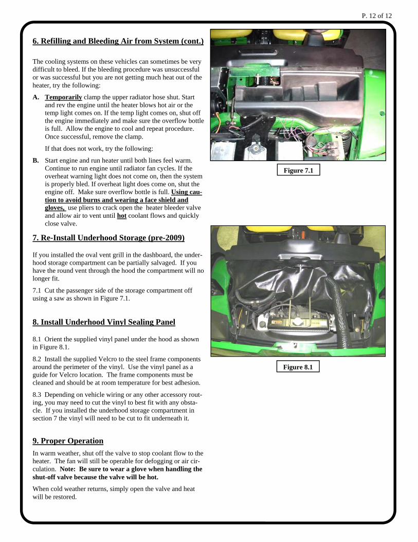
7. Re-Install Underhood Storage (pre-2009)
If you installed the oval vent grill in the dashboard, the under-hood storage compartment can be partially salvaged. If you have the round vent through the hood the compartment will no longer fit.
7.1 Cut the passenger side of the storage compartment off using a saw as shown in Figure 7.1.
8. Install Underhood Vinyl Sealing Panel
8.1 Orient the supplied vinyl panel under the hood as shown in Figure 8.1.
8.2 Install the supplied Velcro to the steel frame components around the perimeter of the vinyl. Use the vinyl panel as a guide for Velcro location. The frame components must be cleaned and should be at room temperature for best adhesion.
8.3 Depending on vehicle wiring or any other accessory rout-ing, you may need to cut the vinyl to best fit with any obsta-cle. If you installed the underhood storage compartment in section 7 the vinyl will need to be cut to fit underneath it.
9. Proper Operation
In warm weather, shut off the valve to stop coolant flow to the heater. The fan will still be operable for defogging or air cir-culation. Note: Be sure to wear a glove when handling the shut-off valve because the valve will be hot.
When cold weather returns, simply open the valve and heat will be restored.
Figure 7.1
Figure 8.1