Embed Size (px)
Citation preview
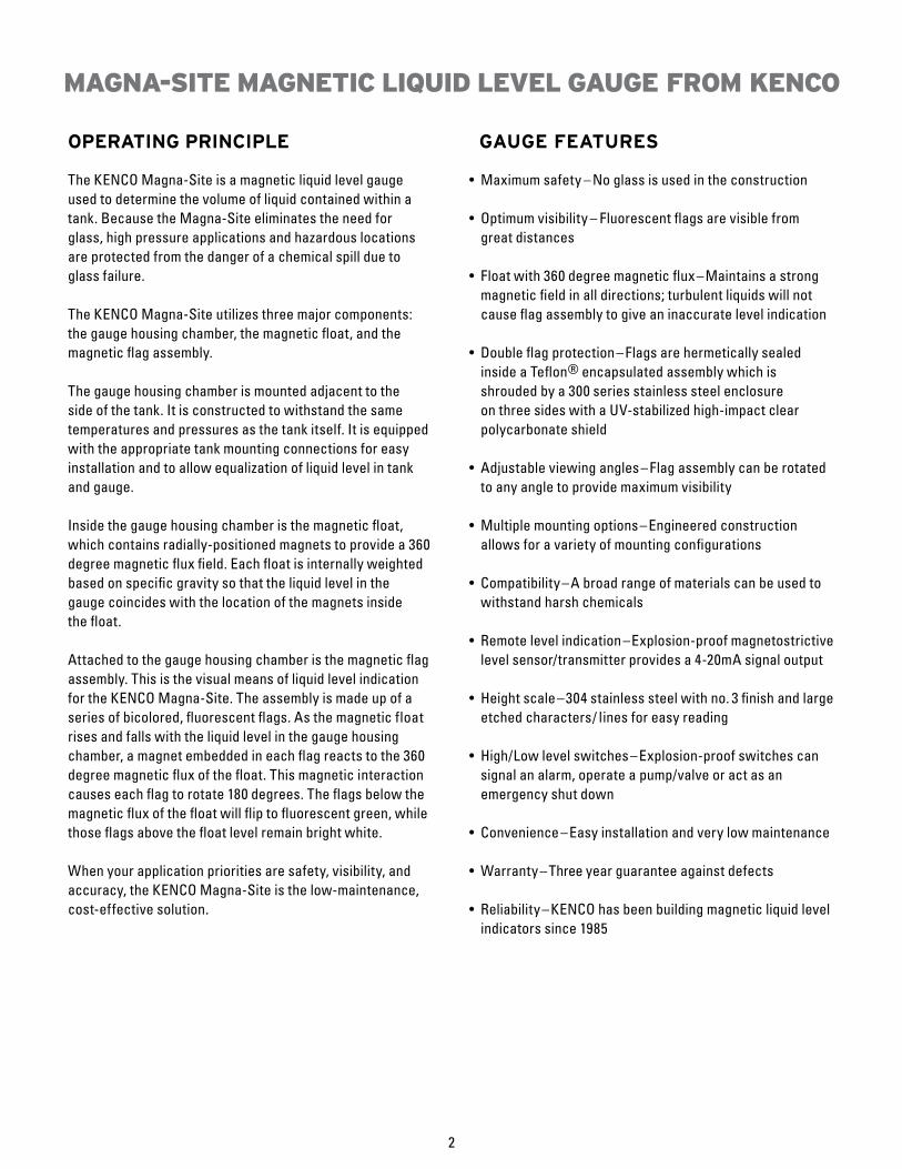
OPERATING PRINCIPLE
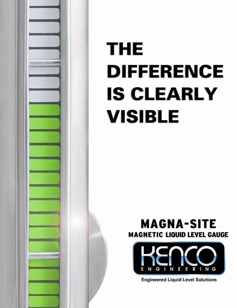
The KENCO Magna-Site is a magnetic liquid level gaugeused to determine the volume of liquid contained within atank. Because the Magna-Site eliminates the need forglass, high pressure applications and hazardous locationsare protected from the danger of a chemical spill due toglass failure.
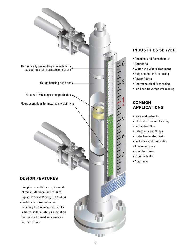
The KENCO Magna-Site utilizes three major components:the gauge housing chamber, the magnetic float, and themagnetic flag assembly.
The gauge housing chamber is mounted adjacent to theside of the tank. It is constructed to withstand the sametemperatures and pressures as the tank itself. It is equippedwith the appropriate tank mounting connections for easyinstallation and to allow equalization of liquid level in tankand gauge. Inside the gauge housing chamber is the magnetic float,which contains radially-positioned magnets to provide a 360degree magnetic flux field. Each float is internally weightedbased on specific gravity so that the liquid level in thegauge coincides with the location of the magnets insidethe float.
Attached to the gauge housing chamber is the magnetic flagassembly. This is the visual means of liquid level indicationfor the KENCO Magna-Site. The assembly is made up of aseries of bicolored, fluorescent flags. As the magnetic float rises and falls with the liquid level in the gauge housing chamber, a magnet embedded in each flag reacts to the 360 degree magnetic flux of the float. This magnetic interaction causes each flag to rotate 180 degrees. The flags below the magnetic flux of the float will flip to fluorescent green, while those flags above the float level remain bright white.
When your application priorities are safety, visibility, andaccuracy, the KENCO Magna-Site is the low-maintenance, cost-effective solution.
GAUGE FEATURES
• Maximum safety – No glass is used in the construction
• Optimum visibility – Fluorescent flags are visible from great distances
• Float with 360 degree magnetic flux–Maintains a strong magnetic field in all directions; turbulent liquids will not cause flag assembly to give an inaccurate level indication
• Double flag protection– Flags are hermetically sealed inside a Teflon® encapsulated assembly which is shrouded by a 300 series stainless steel enclosure on three sides with a UV-stabilized high-impact clear polycarbonate shield
• Adjustable viewing angles– Flag assembly can be rotated to any angle to provide maximum visibility
• Multiple mounting options–Engineered construction allows for a variety of mounting configurations
• Compatibility–A broad range of materials can be used to withstand harsh chemicals
• Remote level indication–Explosion-proof magnetostrictive level sensor/transmitter provides a 4-20mA signal output
• Height scale–304 stainless steel with no. 3 finish and large etched characters/ lines for easy reading
• High/Low level switches–Explosion-proof switches can signal an alarm, operate a pump/valve or act as an emergency shut down
• Convenience–Easy installation and very low maintenance
• Warranty–Three year guarantee against defects
• Reliability–KENCO has been building magnetic liquid level indicators since 1985
MAGNA-SITE MAGNETIC LIQUID LEVEL GAUGE FROM KENCO
2
INDUSTRIES SERVED
• Chemical and Petrochemical
Refineries
• Water and Waste Treatment
• Pulp and Paper Processing
• Power Plants
• Pharmaceutical Processing
• Food and Beverage Processing
COMMONAPPLICATIONS
• Fuels and Solvents
• Oil Production and Refining
• Lubrication Oils
• Detergents and Soaps
• Boiler Feedwater Tanks
• Fertilizers and Pesticides
• Ammonia Tanks
• Scrubber Tanks
• Storage Tanks
• Acid Tanks
Hermetically sealed flag assembly with300 series stainless steel enclosure
Gauge housing chamber
Float with 360 degree magnetic flux
Fluorescent flags for maximum visibility
3
DESIGN FEATURES
• Compliance with the requirements
of the ASME Code for Pressure
Piping, Process Piping, B31.3-2004
• Certificate of Authorization
including CRN numbers issued by
Alberta Boilers Safety Association
for use in all Canadian provinces
and territories
WHAT MAKES THE DIFFERENCE CLEARLY VISIBLE?
FLOAT CHARACTERISTICS
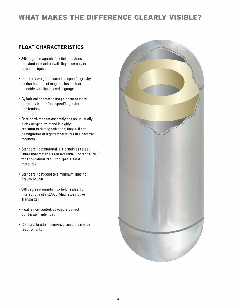
• 360 degree magnetic flux field provides constant interaction with flag assembly in turbulent liquids
• Internally weighted based on specific gravity so that location of magnets inside float coincide with liquid level in gauge
• Cylindrical geometric shape ensures more accuracy in interface specific gravity applications
• Rare earth magnet assembly has an unusually high energy output and is highly resistant to demagnetization; they will not demagnetize at high temperatures like ceramic magnets
• Standard float material is 316 stainless steel. Other float materials are available. Contact KENCO for applications requiring special float materials
• Standard float good to a minimum specific gravity of 0.50
• 360 degree magnetic flux field is ideal for interaction with KENCO Magnetostrictive Transmitter
• Float is non-vented, so vapors cannot condense inside float
• Compact length minimizes ground clearance requirements
4
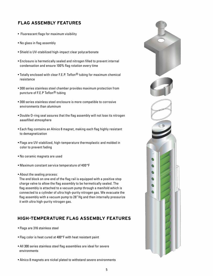
FLAG ASSEMBLY FEATURES
• Fluorescent flags for maximum visibility
• No glass in flag assembly
• Shield is UV-stabilized high-impact clear polycarbonate
• Enclosure is hermetically sealed and nitrogen filled to prevent internal condensation and ensure 100% flag rotation every time
• Totally enclosed with clear F.E.P. Teflon® tubing for maximum chemical resistance
• 300 series stainless steel chamber provides maximum protection from puncture of F.E.P Teflon® tubing
• 300 series stainless steel enclosure is more compatible to corrosive environments than aluminum
• Double O-ring seal assures that the flag assembly will not lose its nitrogen aaaafilled atmosphere
• Each flag contains an Alnico 8 magnet, making each flag highly resistant to demagnetization
• Flags are UV-stabilized, high-temperature thermoplastic and molded in color to prevent fading
• No ceramic magnets are used
• Maximum constant service temperature of 400 °F
• About the sealing process: The end block on one end of the flag rail is equipped with a positive stop charge valve to allow the flag assembly to be hermetically sealed. The flag assembly is attached to a vacuum pump through a manifold which is connected to a cylinder of ultra high-purity nitrogen gas. We evacuate the flag assembly with a vacuum pump to 28” Hg and then internally pressurize it with ultra high-purity nitrogen gas.
• Flags are 316 stainless steel
• Flag color is heat cured at 400°F with heat resistant paint
• All 300 series stainless steel flag assemblies are ideal for severe environments
• Alnico 8 magnets are nickel plated to withstand severe environments
5
HIGH-TEMPERATURE FLAG ASSEMBLY FEATURES
"L"
FLOATLENGTH
MIN.LEVEL
LEVELMAX.
418 "
(MIN.)
5"
278 "Ø
2 916 "
(REF.)
7"Ø (MIN.)1516 "
(MIN.)
"L"
"L"
"B"
678 "
278 "Ø
712 "Ø (REF.)
238 "Ø
2 516 "
(REF.)
1"
OF TANKBOTTOM
3" 150 LB.R.F. FLANGE
MAX. LEVEL
MIN. LEVEL
MIN. LEVEL
MAX. LEVEL
378 "
(MIN.)
11316"
"A"
"C"
TANKEXISTING
FLANGE
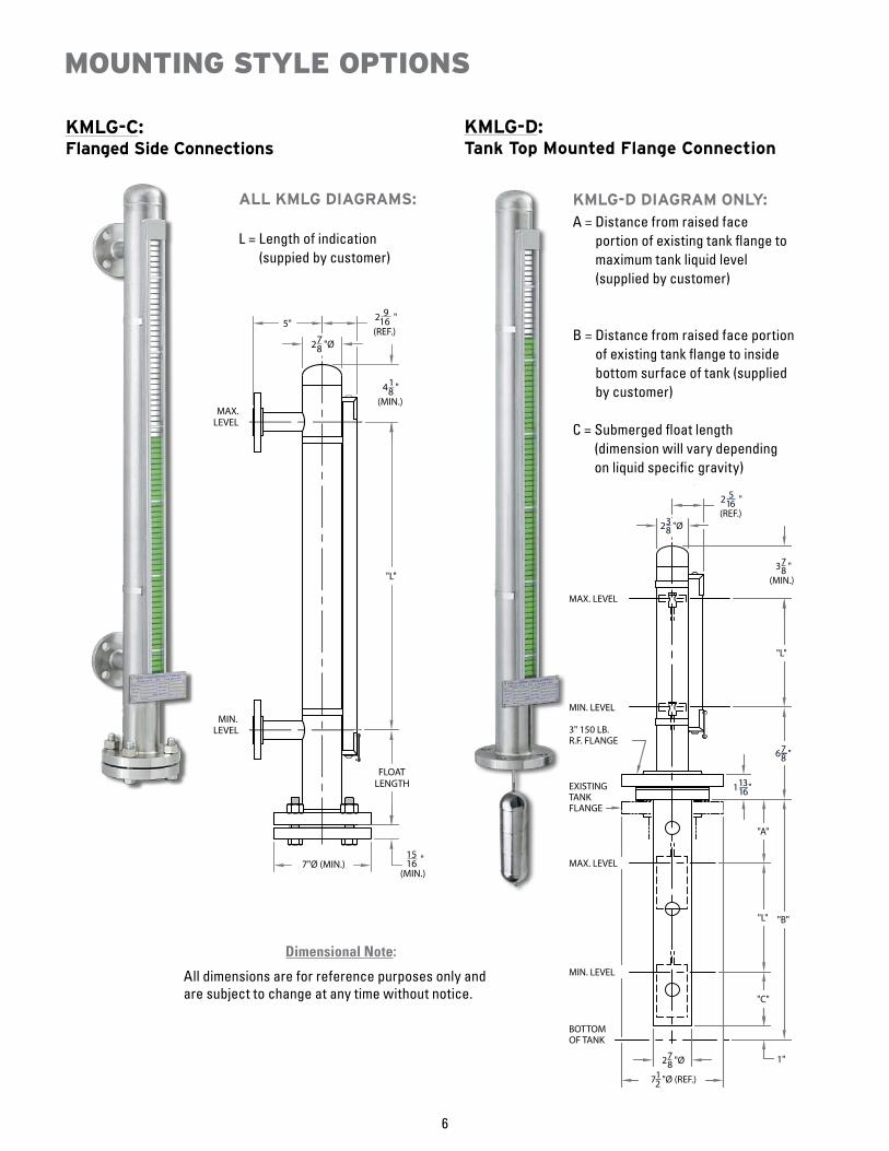
KMLG-C: Flanged Side Connections
KMLG-D:Tank Top Mounted Flange Connection
ALL KMLG DIAGRAMS:
L = Length of indication (suppied by customer)
KMLG-D DIAGRAM ONLY:A = Distance from raised face
portion of existing tank flange to maximum tank liquid level (supplied by customer)
B = Distance from raised face portion of existing tank flange to inside bottom surface of tank (supplied by customer)
C = Submerged float length (dimension will vary depending on liquid specific gravity)
MOUNTING STYLE OPTIONS
6
Dimensional Note:
All dimensions are for reference purposes only and are subject to change at any time without notice.
2 916 "
(REF.)27
8 "Ø
"L"
FLOATLENGTH
"L"
418 "
(MIN.)5 1
16 "(MIN.) MAX.
LEVEL
LEVELMIN.MIN.
LEVEL
LEVELMAX.
7"Ø (MIN.)
FLOATLENGTH
278 "Ø
2 916 "
(REF.)31
2 "
7"Ø (MIN.)1516 "
(MIN.)
1516 "
(MIN.)
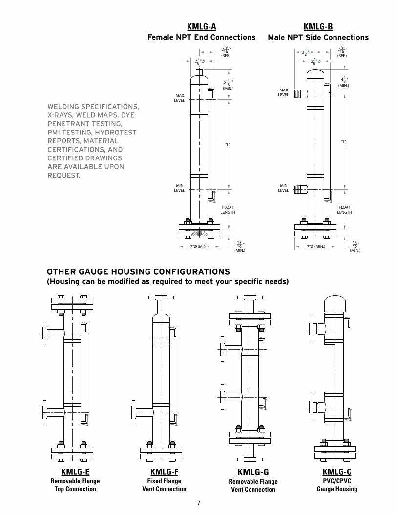
KMLG-C PVC/CPVC
Gauge Housing
KMLG-ERemovable Flange
Top Connection
KMLG-F Fixed Flange
Vent Connection
KMLG-G Removable FlangeVent Connection
OTHER GAUGE HOUSING CONFIGURATIONS(Housing can be modified as required to meet your specific needs)
WELDING SPECIFICATIONS, X-RAYS, WELD MAPS, DYE PENETRANT TESTING, PMI TESTING, HYDROTEST REPORTS, MATERIAL CERTIFICATIONS, AND CERTIFIED DRAWINGS ARE AVAILABLE UPON REQUEST.
Female NPT End Connections Male NPT Side ConnectionsKMLG-A KMLG-B
7
KENCO MAGNETOSTRICTIVE TRANSMITTER
TRANSMITTER FEATURES• Digital display for zero and span settings and readout• Readout available as a % of span, 4-20mA, Feet, Inches, Meters,
Centimeters, or Millimeters• CSA certified explosion-proof housing• CSA and ATEX certified as intrinsically safe• Process temperature range: -40 to 400°F
(contact KENCO for higher temperature requirements)• No maintenance required• Immune from electrical and mechanical noise• HART® Communications standard
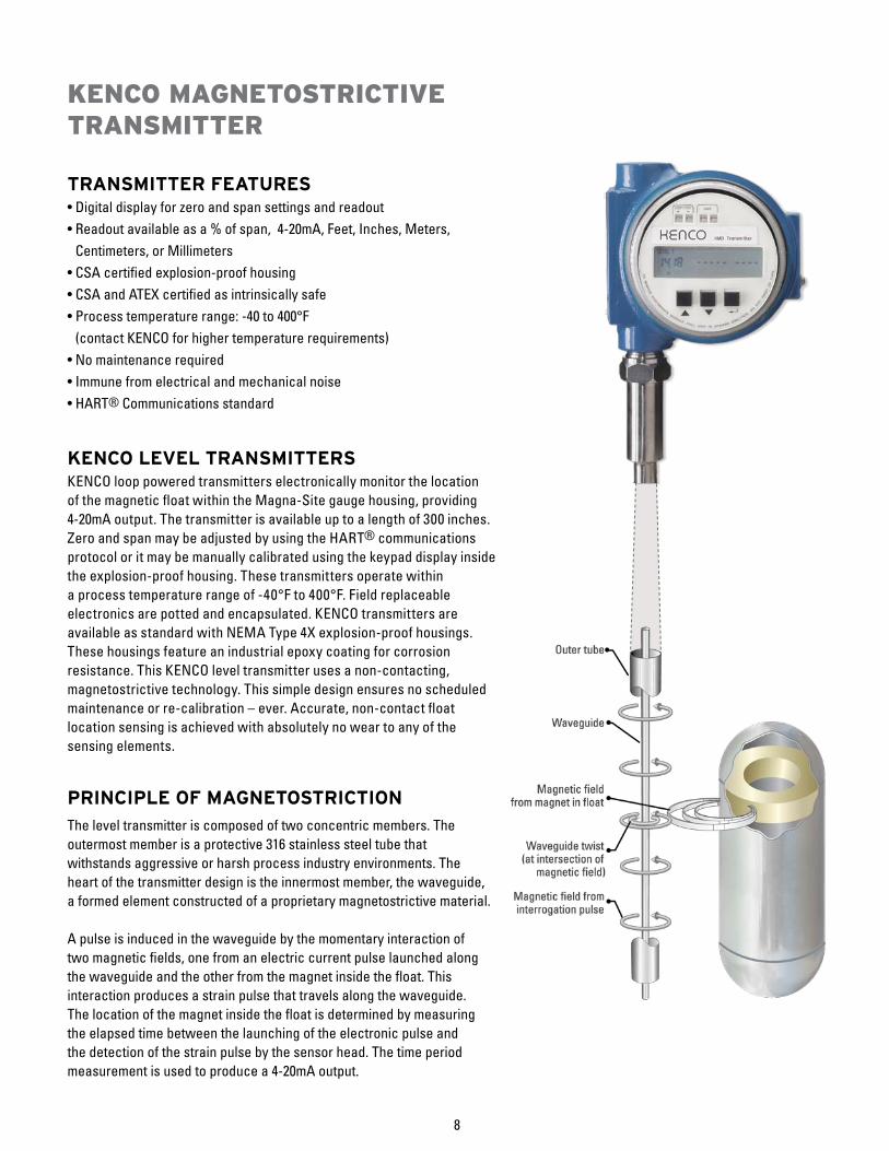
KENCO LEVEL TRANSMITTERSKENCO loop powered transmitters electronically monitor the locationof the magnetic float within the Magna-Site gauge housing, providing4-20mA output. The transmitter is available up to a length of 300 inches. Zero and span may be adjusted by using the HART® communications protocol or it may be manually calibrated using the keypad display inside the explosion-proof housing. These transmitters operate within a process temperature range of -40°F to 400°F. Field replaceable electronics are potted and encapsulated. KENCO transmitters are available as standard with NEMA Type 4X explosion-proof housings. These housings feature an industrial epoxy coating for corrosion resistance. This KENCO level transmitter uses a non-contacting, magnetostrictive technology. This simple design ensures no scheduled maintenance or re-calibration – ever. Accurate, non-contact float location sensing is achieved with absolutely no wear to any of the sensing elements.
PRINCIPLE OF MAGNETOSTRICTION
The level transmitter is composed of two concentric members. Theoutermost member is a protective 316 stainless steel tube thatwithstands aggressive or harsh process industry environments. Theheart of the transmitter design is the innermost member, the waveguide,a formed element constructed of a proprietary magnetostrictive material.
A pulse is induced in the waveguide by the momentary interaction oftwo magnetic fields, one from an electric current pulse launched alongthe waveguide and the other from the magnet inside the float. Thisinteraction produces a strain pulse that travels along the waveguide.The location of the magnet inside the float is determined by measuringthe elapsed time between the launching of the electronic pulse andthe detection of the strain pulse by the sensor head. The time periodmeasurement is used to produce a 4-20mA output.
8
J6
J3
J4
J2
J1
J7
+ -
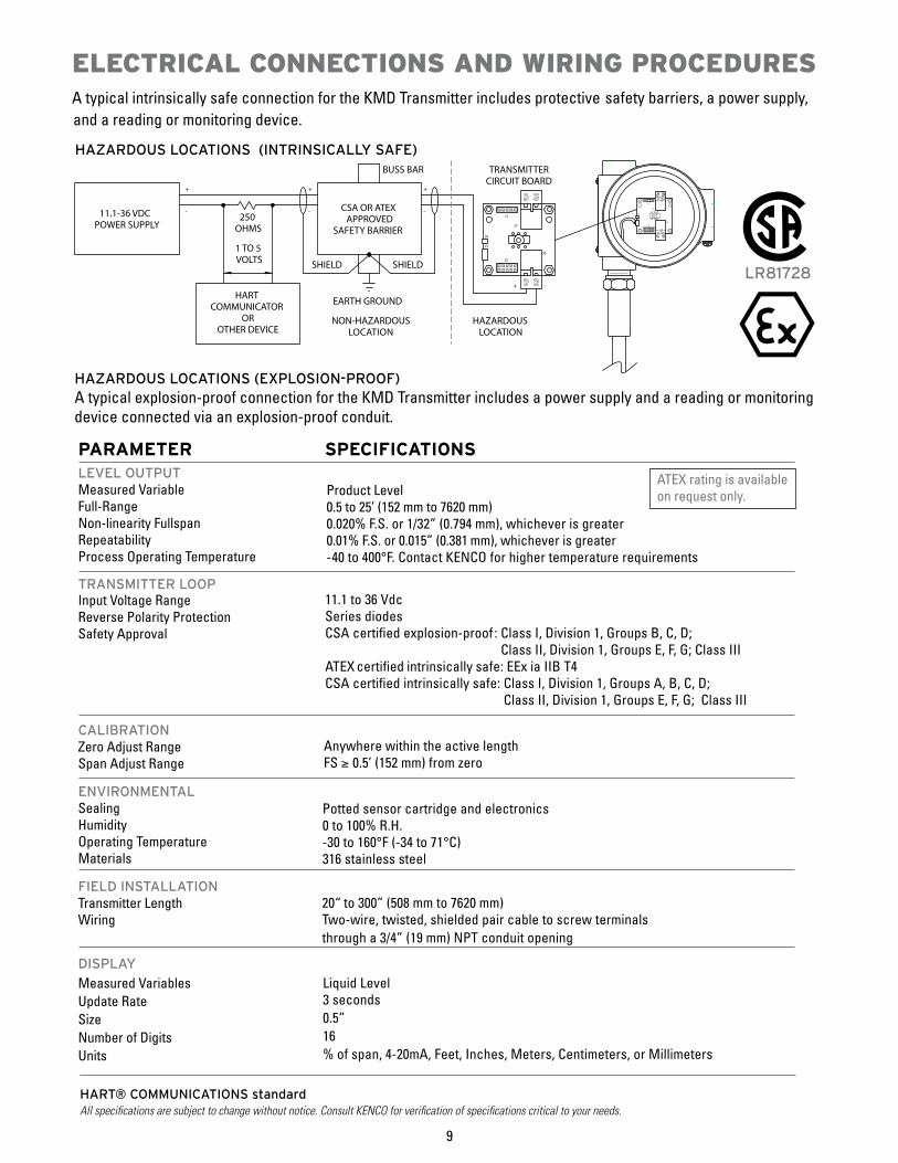
CSA OR ATEXAPPROVED
SAFETY BARRIER
11.1-36 VDCPOWER SUPPLY
BUSS BAR
EARTH GROUNDHART COMMUNICATOR
OROTHER DEVICE
250OHMS
1 TO 5VOLTS
+
-
SHIELD SHIELD
HAZARDOUSLOCATION
-
+
-
+
TRANSMITTERCIRCUIT BOARD
J3
J4
J1
J7
J2
J6
NON-HAZARDOUSLOCATION
HAZARDOUS LOCATIONS (EXPLOSION-PROOF)A typical explosion-proof connection for the KMD Transmitter includes a power supply and a reading or monitoring device connected via an explosion-proof conduit.
PARAMETERLEVEL OUTPUTMeasured VariableFull-RangeNon-linearity FullspanRepeatabilityProcess Operating Temperature
TRANSMITTER LOOPInput Voltage RangeReverse Polarity ProtectionSafety Approval
CALIBRATIONZero Adjust RangeSpan Adjust Range
ENVIRONMENTALSealingHumidityOperating TemperatureMaterials
FIELD INSTALLATIONTransmitter Length Wiring
DISPLAY
Measured VariablesUpdate RateSizeNumber of DigitsUnits
20“ to 300” (508 mm to 7620 mm)Two-wire, twisted, shielded pair cable to screw terminalsthrough a 3/4” (19 mm) NPT conduit opening
Product Level0.5 to 25’ (152 mm to 7620 mm)0.020% F.S. or 1/32” (0.794 mm), whichever is greater0.01% F.S. or 0.015” (0.381 mm), whichever is greater-40 to 400°F. Contact KENCO for higher temperature requirements
SPECIFICATIONS
Anywhere within the active lengthFS ≥ 0.5’ (152 mm) from zero
11.1 to 36 VdcSeries diodesCSA certified explosion-proof : Class I, Division 1, Groups B, C, D;
Class II, Division 1, Groups E, F, G; Class IIIATEX certified intrinsically safe: EEx ia IIB T4CSA certified intrinsically safe: Class I, Division 1, Groups A, B, C, D;
Class II, Division 1, Groups E, F, G; Class III
Potted sensor cartridge and electronics0 to 100% R.H.-30 to 160°F (-34 to 71°C)316 stainless steel
Liquid Level3 seconds0.5”16% of span, 4-20mA, Feet, Inches, Meters, Centimeters, or Millimeters
9
HAZARDOUS LOCATIONS (INTRINSICALLY SAFE)
ATEX rating is available on request only.
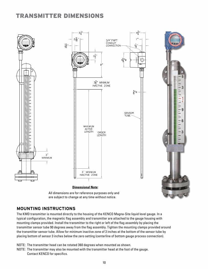
MOUNTING INSTRUCTIONSThe KMD transmitter is mounted directly to the housing of the KENCO Magna-Site liquid level gauge. In a typical configuration, the magnetic flag assembly and transmitter are attached to the gauge housing with mounting clamps provided. Install the transmitter to the right or left of the flag assembly by placing the transmitter sensor tube 90 degrees away from the flag assembly. Tighten the mounting clamps provided around the transmitter sensor tube. Allow for minimum inactive zone of 3 inches at the bottom of the sensor tube by placing bottom of sensor 3 inches below the zero setting (centerline of bottom gauge process connection).
NOTE: The transmitter head can be rotated 360 degrees when mounted as shown.NOTE: The transmitter may also be mounted with the transmitter head at the foot of the gauge.
Contact KENCO for specifics.
TRANSMITTER DIMENSIONS
10
Dimensional Note:
All dimensions are for reference purposes only and are subject to change at any time without notice.
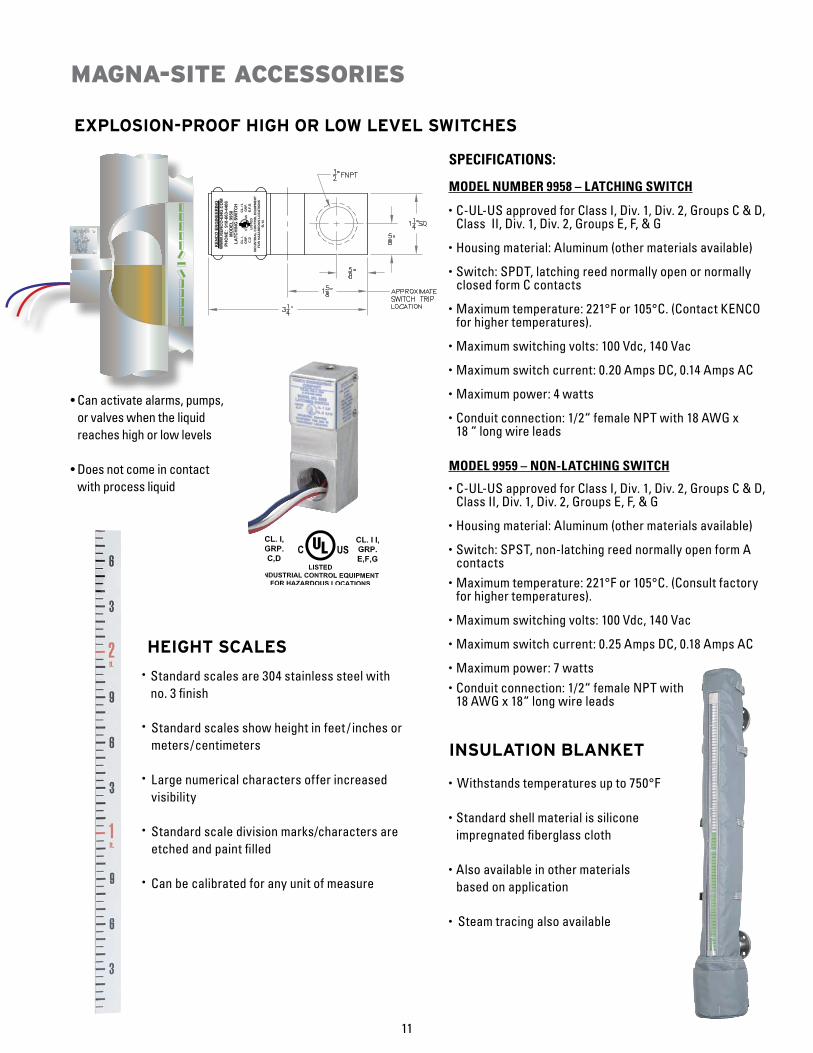
SPECIFICATIONS:
MODEL NUMBER 9958 – LATCHING SWITCH
• C-UL-US approved for Class I, Div. 1, Div. 2, Groups C & D, Class II, Div. 1, Div. 2, Groups E, F, & G
• Housing material: Aluminum (other materials available)
• Switch: SPDT, latching reed normally open or normally closed form C contacts
• Maximum temperature: 221°F or 105°C. (Contact KENCO for higher temperatures).
• Maximum switching volts: 100 Vdc, 140 Vac
• Maximum switch current: 0.20 Amps DC, 0.14 Amps AC
• Maximum power: 4 watts
• Conduit connection: 1/2“ female NPT with 18 AWG x 18 “ long wire leads
MODEL 9959 – NON-LATCHING SWITCH
• C-UL-US approved for Class I, Div. 1, Div. 2, Groups C & D, Class II, Div. 1, Div. 2, Groups E, F, & G
• Housing material: Aluminum (other materials available)
• Switch: SPST, non-latching reed normally open form A contacts
• Maximum temperature: 221°F or 105°C. (Consult factory for higher temperatures).
• Maximum switching volts: 100 Vdc, 140 Vac
• Maximum switch current: 0.25 Amps DC, 0.18 Amps AC
• Maximum power: 7 watts• Conduit connection: 1/2“ female NPT with
18 AWG x 18“ long wire leads
INSULATION BLANKET
• Withstands temperatures up to 750°F • Standard shell material is silicone
impregnated fiberglass cloth
• Also available in other materials based on application
• Steam tracing also available
11
MAGNA-SITE ACCESSORIES
EXPLOSION-PROOF HIGH OR LOW LEVEL SWITCHES
• Can activate alarms, pumps, or valves when the liquid reaches high or low levels
• Does not come in contact with process liquid
HEIGHT SCALES
• Standard scales are 304 stainless steel with no. 3 finish
• Standard scales show height in feet / inches or meters/centimeters
• Large numerical characters offer increased visibility
• Standard scale division marks/characters are etched and paint filled
• Can be calibrated for any unit of measure
Baton Rouge Office11616 Industriplex, Suite 7
Baton Rouge, LA 70809phone 225.755.1912
fax 225.755.1913www.kenco-eng.com
email: [email protected]
6-10-10Headquarters
10001 E 54th St.Tulsa, Oklahoma 74146
phone 918.663.4406fax 918.663.4480
www.kenco-eng.comemail: [email protected]
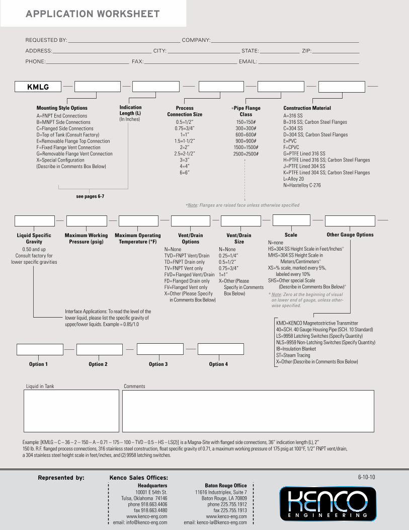
Requested by: company:
addRess: cIty: state: zIp:
pHone: FaX: emaIL:
APPLICATION WORKSHEET
*Pipe FlangeClass
150=150#300=300#600=600#900=900#
1500=1500#2500=2500#
Construction MaterialA=316 SSB=316 SS; Carbon Steel FlangesC=304 SSD=304 SS; Carbon Steel FlangesE=PVCF=CPVCG=PTFE Lined 316 SSH=PTFE Lined 316 SS; Carbon Steel FlangesJ=PTFE Lined 304 SSK=PTFE Lined 304 SS; Carbon Steel FlangesL=Alloy 20N=Hastelloy C-276
Mounting Style Options
A=FNPT End ConnectionsB=MNPT Side ConnectionsC=Flanged Side ConnectionsD=Top of Tank (Consult Factory)E= Removable Flange Top ConnectionF=Fixed Flange Vent ConnectionG= Removable Flange Vent Co nnectionX=Special Configuration(Describe in Comments Box Below)
ProcessConnection Size
0.5=1/2”0.75=3/4”
1=1”1.5=1-1/2”
2=2”2.5=2-1/2”
3=3”4=4”6=6”
KMLG
IndicationLength (L)(In Inches)
see pages 6-7
*Note: Flanges are raised face unless otherwise specified
Liquid SpecificGravity
0.50 and upConsult factory for
lower specific gravities
Maximum WorkingPressure (psig)
Maximum OperatingTemperature (°F)
Vent /Drain Options
N=NoneTVD=FNPT Vent/DrainTD=FNPT Drain onlyTV=FNPT Vent onlyFVD= Flanged Vent/DrainFD=Flanged Drain onlyFV=Flanged Vent onlyX=Other (Please Specify in Comments Box Below)
Vent /Drain SizeN=None0.25=1/4”0.5=1/2” 0.75=3/4”1=1”X= Other (Please
Specify in Comments Box Below)
ScaleN=noneHS=304 SS Height Scale in Feet/Inches*MHS= 304 SS Height Scale in
Meters/Centimeters*XS= % scale, marked every 5%,
labeled every 10%SHS= Other special Scale
(Describe in Comments Box Below)** Note: Zero at the beginning of visual
on lower end of gauge, unless other-wise specified.
Other Gauge Options
KMD=KENCO Magnetostrictive Transmitter40=SCH. 40 Gauge Housing Pipe (SCH. 10 Standard)LS=9958 Latching Switches (Specify Quantity)NLS=9959 Non-Latching Switches (Specify Quantity)IB=Insulation BlanketST=Steam TracingX=Other (Describe in Comments Box Below)Option 1 Option 2 Option 3 Option 4
CommentsLiquid in Tank
Example: [KMLG – C – 36 – 2 – 150 – A – 0.71 – 175 – 100 – TVD – 0.5 – HS – LS(2)] is a Magna-Site with flanged side connections, 36” indication length (L), 2” 150 lb. R.F. flanged process connections, 316 stainless steel construction, float specific gravity of 0.71, a maximum working pressure of 175 psig at 100°F, 1/2” FNPT vent/drain,a 304 stainless steel height scale in feet/inches, and (2) 9958 latching switches.
Interface Applications: To read the level of thelower liquid, please list the specific gravity ofupper/lower liquids. Example = 0.85/1.0


![CV Hand Valves 91197 - Zimco Instrumentation Inc. · The CM1B (6000 psig [414 barg] barstock construction valve features a straight-through (roddable) 3/8” [9.5 mm] bore.This bi-directional](https://img.pdfslide.net/doc/110x75/5f01ccd97e708231d4011934/cv-hand-valves-91197-zimco-instrumentation-inc-the-cm1b-6000-psig-414-barg.jpg)