Embed Size (px)
Citation preview
7/27/2019 Gauges Ashcroft - 7 Steps to select a PG.pdf
http://slidepdf.com/reader/full/gauges-ashcroft-7-steps-to-select-a-pgpdf 1/2
Seven Steps to Selecta Pressure Gauge
Pressure Gauge Options
BULLETIN G7
Ashcroft In c., 250 East Main Street, StratTel: 203-378-8281 • Fax: 203-385-0408
email: [email protected] • www.ashcro
All speci fications are subject to change wit hout notice. All sales subject to standard terms and conditi ons.
© Ashcroft Inc. 2009 10/09
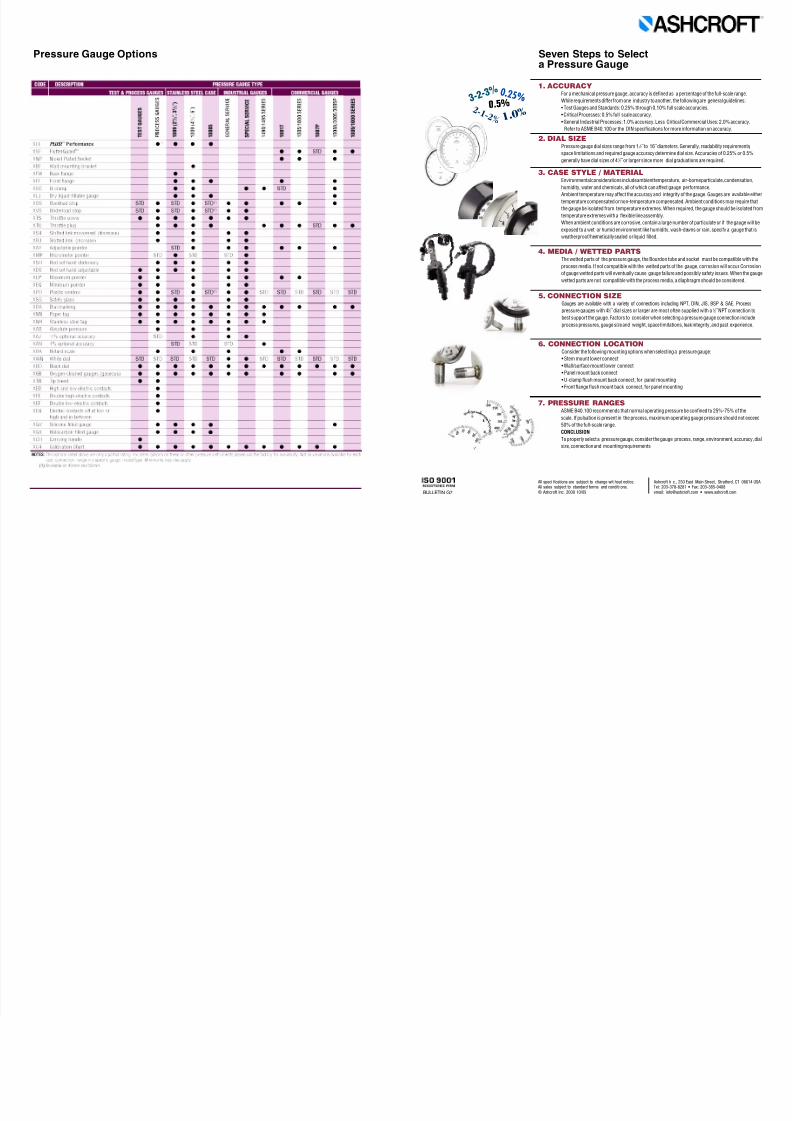
4. MEDIA / WETTED PARTSThe wetted parts of the pressure gauge, the Bourdon tube and socket must be com
process media. If not compatible with the wetted parts of the gauge, corrosion will
of gauge wetted parts will eventually cause gauge failure and possibly safety issues
wetted parts are not compatible with the process media, a diaphragm should be co
7. PRESSURE RANGESASME B40.100 recommends that normal operating pressure be confined to 25%-7
scale. If pulsation is present in the process, maximum operating gauge pressure sh
50% of the full-scale range.
CONCLUSION
To properly select a pressure gauge, consider the gauge process, range, environme
size, connection and mounting requirements.
3. CASE STYLE / MATERIALEnvironmental considerations include ambient temperature, air-borne particulate, c
humidity, water and chemicals, all of which can affect gauge performance.
Ambient temperature may affect the accuracy and integrity of the gauge. Gauges ar
temperature compensated or non-temperature compensated. Ambient conditions m
the gauge be isolated from temperature extremes. When required, the gauge shoul
temperature extremes with a flexible line assembly.
When ambient conditions are corrosive, contain a large number of particulate or if
exposed to a wet or humid environment like humidity, wash-downs or rain, specify
weatherproof/hermetically sealed or liquid filled.
1. ACCURACYFor a mechanical pressure gauge, accuracy is defined as a percentage of the full-sc
While requirements differ from one industry to another, the following are general g
• Test Gauges and Standards: 0.25% through 0.10% full scale accuracies.
• Critical Processes: 0.5% full scale accuracy.
• General Industrial Processes: 1.0% accuracy. Less Critical Commercial Uses: 2.0%
Refer to ASME B40.100 or the DIN specifications for more information on accura
2. DIAL SIZEPressure gauge dial sizes range from 1 1 ⁄ 2˝ to 16˝ diameters. Generally, readability re
space limitations and required gauge accuracy determine dial size. Accuracies of 0.
generally have dial sizes of 4 1 ⁄ 2˝ or larger since more dial graduations are required.
5. CONNECTION SIZEGauges are available with a variety of connections including NPT, DIN, JIS, BSP &
pressure gauges with 41 ⁄ 2˝ dial sizes or larger are most often supplied with a 1 ⁄ 2˝ NPT
best support the gauge. Factors to consider when selecting a pressure gauge conn
process pressures, gauge size and weight, space limitations, leak integrity, and pas
6. CONNECTION LOCATIONConsider the following mounting options when selecting a pressure gauge:
• Stem mount lower connect
• Wall/surface mount lower connect
• Panel mount back connect
• U-clamp flush mount back connect, for panel mounting
• Front flange flush mount back connect, for panel mounting
3 - 2 - 3 %
2 - 1 - 2 % 1. 0 %
0 . 2 5 % 0.5 %
7/27/2019 Gauges Ashcroft - 7 Steps to select a PG.pdf
http://slidepdf.com/reader/full/gauges-ashcroft-7-steps-to-select-a-pgpdf 2/2
2089208620841084108212791377137924621259
T5500T65001008S1008S
1008S (02C)10091109101010171220
1020S10381339
1150H11221187
11881189149014951125
1125A55035509112711281130113111321133113410321036
2030 Series1001T1005
1005P1005S1000
1007P1008A
2071A30053005P
12MFX/15MFX12DDG/15DDG
23DDG40DDG/50DDG
208920862084
2070 SeriesD1005P
0 . 0
5 % S p a n
0 . 1
0 % S p a n
0 . 2
5 % S p a n
0 . 5
%
S p a n
1 % S p a n
1 % a t 0 ,
2 %
3 / 4 s c a l e ,
5 % l a s t 1 / 4 s c a l e
2 % , 1
% , 2
%
1 . 5
%
S p a n
1 . 6
%
S p a n
2 % S p a n
2 % a t s e t p o i n t
2 . 5
%
S p a n
3 % ,
2 % ,
3 %
3 % u p s c a l e ,
5 %
d o w n s c a l e
3 . 5
%
5 % S p a n
2 3 m m
1 1
⁄ 4 I n c h e s
1 1
⁄ 2 I n c h e s ,
4 0 m m
2 . 0
I n c h e s ,
5 0 m m
2 . 5
I n c h e s ,
6 3 m m
3 I n c h e s
3 . 5
I n c h e s
4 I n c h e s ,
1 0 0 m m
4 . 5
I n c h e s
6 I n c h e s ,
1 6 0 m m
8 . 5
I n c h e s
1 2 I n c h e s
O p e n F r o n t
S o l i d F r o n t
T h e r m o s e t o r T h e r m o p l a s t i c C a s e
A l u m i n u m
S t a i n l e s s S t e e l
B l a c k M e t a l
A l u m i n u m
B r o n z e / B r a s s
B e r y l l i u m C o p p e r / B r a s s
S t e e l
3 1 6 S t a i n l e s s S t e e l / C a r b o n S t e e l S o c k e t
3 1 6 S t a i n l e s s S t e e l
S t a i n l e s s S t e e l
M o n e l
I n c o n e l
1 ⁄ 8 N P T
1 ⁄ 4 N P T
1 ⁄ 2 N P T
1 ⁄ 4 ˝ H i g h P r e s s u r e
T r i - C l a m p T y p e
L o w e r
B a c k
I n - L i n e
I n c h e s o f W a t e r - i n c l . I W v
a c u u m a n d c o m p o u n d
0 - 6 0 0 P S I ( i n c l u d i n g v a c u u m
& c o m p o u n d )
0 - 1 0 0 0 P S I ( i n c l u d i n g v a c u u m
& c o m p o u n d )
0 - 6 0 0 0 P S I ( i n c l u d i n g v a c u u m
& c o m p o u n d )
0 - 7 0 0 0 P S I ( i n c l u d i n g v a c u u m
& c o m p o u n d )
0 - 1 0 , 0
0 0 P S I ( i n c l u d i n g v a c u u m & c o m p o u n d )
0 - 1 5 , 0
0 0 P S I ( i n c l u d i n g v a c u u m & c o m p o u n d )
0 - 2 0 , 0
0 0 P S I ( i n c l u d i n g v a c u u m & c o m p o u n d )
0 - 3 0 , 0
0 0 P S I ( i n c l u d i n g v a c u u m & c o m p o u n d )
0 - 1 0 0 , 0
0 0 P S I ( i n c l u d i n g v a c u u m & c o m p o u n d )
A b s o l u t e
0 - 1 I W I D t o 5 0 I W D
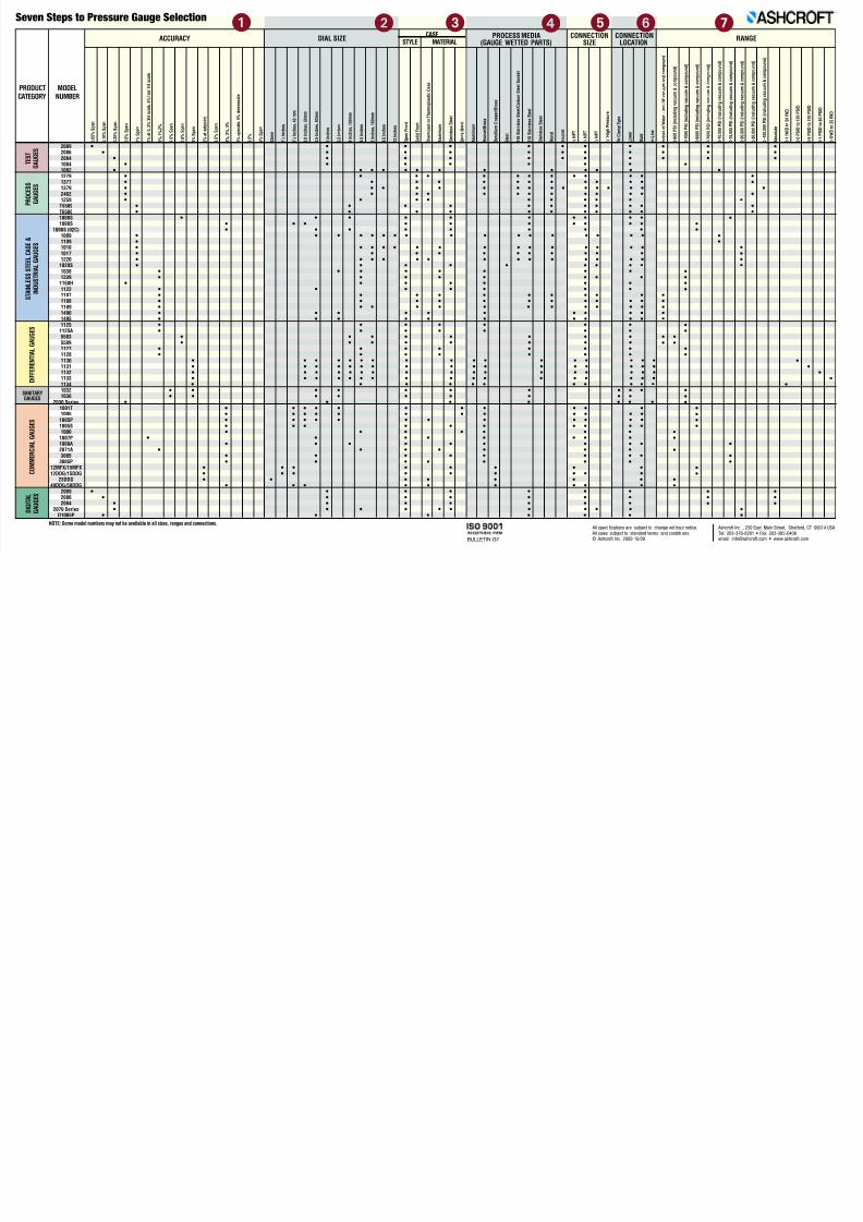
ACCURACY
Seven Steps to Pressure Gauge Selection
DIAL SIZECASE
STYLE MATERIALRANGEPROCESS MEDIA
(GAUGE WETTED PARTS)CONNECTION
SIZECONNECTION
LOCATION
MODELNUMBER
D I F F E R E N T I A L G A U G E S
C O M M E R C
I A L G A U G E S
S T A I N L E S S S T E E L C A S E &
I N D U S T R I A L G A U G E S
P R O C E S S
G A U G E S
T E S T
G A U G E S
D I G I T A L
G A U G E S
SANITARYGAUGES
NOTE: Some model numbers may not be available in all sizes, ranges and connections.
PRODUCTCATEGORY
BULLETIN G7
Ashcroft Inc ., 250 East Main Street, S
Tel: 203-378-8281 • Fax: 203-385-0email: [email protected] • www.ash
All speci fications are subject to change wit hout notice.
All sales subject to standard terms and conditi ons.© Ashcroft Inc. 2009 10/09
1 2 7653 4
• • • • • • • •• • • • • • • •
• • • • • • • •• • • • • • •
• • • • • • • • • • • •• • • • • • • • • • • •• • • • • • • • • • • •• • • • • • • • • • • • • • •• • • • • • • • • • • •• • • • • • • • •
• • • • • • • • • •• • • • • • • • • •
• • • • • • • • • •• • • • • • • • • •• • • • • • • •
• • • • • • • • • • • • • • • • ••• • • • • • • • • • • • • • •• • • • • • • • • • •• • • • • • • • • • • • • •• • • • • • • • •
• • • • • • • •• • • • • • • •
• • • • • • •• • • • • • •• • • • • • • • • •
• • • • • • • • • • •• • • • • • • • • • • •• • • • • • • • • •• • • • • • • • • •• • • • • • •• • • • • • •
• • • • • • • •• • • • • • • •
• • • • • • •• • • • • • •
• • • • • • • • • • • • • • • • •• • • • • • • • • • • • • • • • •• • • • • • • • • • • • • • • • •• • • • • • • • • • • • • • • • •• • • • • • • • • • •
• • • • • • • • • •• • • • • • • • •
• • • • • • •• • • • • • • • • • •• • • • • • • • • • • •• • • • • • • • • • • •• • • • • • • • • •• • • • • • •
• • • • • • • •• • • • • • • • •
• • • • • • •• • • • • • • •• • • • • • •
• • • • • • • •• • • • • • • • •• • • • • • •
• • • • • • • • •• • • • • • •
• • • • • • •• • • • • • •• • • • • • • • • •
• • • • • •
• • •• • •• • •
••
••
••
•••
•••
••
••••
••••
•
••••
••
• •• •
••
••••
••••
••
•
• ••
••
••
• •• •• •
••