Embed Size (px)
Citation preview
GB . . . . . . . .GH2 .F .Ceiling .Hoists
Vers . .1 .00
© G
uldm
ann
GB
-881
/08/
08 •
# 9
0069
0

2
© G
uldm
ann
GB
-881
/08/
08 •
# 9
0069
0
© G
uldm
ann
GB
-881
/08/
08 •
# 9
0069
0
© G
uldm
ann
GB
-881
/08/
08 •
# 9
0069
0
© G
uldm
ann
GB
-881
/08/
08 •
# 9
0069
0
. GH2 .F .Ceiling .Hoists
Hoist .numbers:12xxxx - xxxx
1 .00 . . . . . . . . . .Purpose .and .use . . . . . . . . . . . . . . . . . . . . . . . . . . . . . . . . . . . . . . . . . . . . . . . . 41.01 . . . . . . . . . Manufacturer . . . . . . . . . . . . . . . . . . . . . . . . . . . . . . . . . . . . . . . . . . . . . . . . . . 41.02 . . . . . . . . . Purpose . . . . . . . . . . . . . . . . . . . . . . . . . . . . . . . . . . . . . . . . . . . . . . . . . . . . . . 41.03 . . . . . . . . . Important/precautions . . . . . . . . . . . . . . . . . . . . . . . . . . . . . . . . . . . . . . . . . . . 41.04 . . . . . . . . . Load limits on your GH2 F system . . . . . . . . . . . . . . . . . . . . . . . . . . . . . . . . . 5
2 .00 . . . . . . . . . .Unpacking .and .preparation . . . . . . . . . . . . . . . . . . . . . . . . . . . . . . . . . . . . . . . 52.01 . . . . . . . . . Mounting the lifting hanger before use . . . . . . . . . . . . . . . . . . . . . . . . . . . . . . 6
3 .00 . . . . . . . . . . Lifting .sling . . . . . . . . . . . . . . . . . . . . . . . . . . . . . . . . . . . . . . . . . . . . . . . . . . . . 73.01 . . . . . . . . . Swing kit. . . . . . . . . . . . . . . . . . . . . . . . . . . . . . . . . . . . . . . . . . . . . . . . . . . . . . 8
4 .00 . . . . . . . . . .Before .the .hoist .can .be .used . . . . . . . . . . . . . . . . . . . . . . . . . . . . . . . . . . . . . 84.01 . . . . . . . . . Power supply . . . . . . . . . . . . . . . . . . . . . . . . . . . . . . . . . . . . . . . . . . . . . . . . . 8
5 .00 . . . . . . . . . .Description .of .functions . . . . . . . . . . . . . . . . . . . . . . . . . . . . . . . . . . . . . . . . . 95.01 . . . . . . . . . Pictograms . . . . . . . . . . . . . . . . . . . . . . . . . . . . . . . . . . . . . . . . . . . . . . . . . . . . 95.02 . . . . . . . . . Example of a serial number label . . . . . . . . . . . . . . . . . . . . . . . . . . . . . . . . . 105.03 . . . . . . . . . Audio signals . . . . . . . . . . . . . . . . . . . . . . . . . . . . . . . . . . . . . . . . . . . . . . . . . 105.04 . . . . . . . . . Indicator lamps. . . . . . . . . . . . . . . . . . . . . . . . . . . . . . . . . . . . . . . . . . . . . . . . 10
6 .00 . . . . . . . . . .Operation . . . . . . . . . . . . . . . . . . . . . . . . . . . . . . . . . . . . . . . . . . . . . . . . . . . . 106.01 . . . . . . . . . Installation . . . . . . . . . . . . . . . . . . . . . . . . . . . . . . . . . . . . . . . . . . . . . . . . . . . 126.02 . . . . . . . . . Deinstallation . . . . . . . . . . . . . . . . . . . . . . . . . . . . . . . . . . . . . . . . . . . . . . . . . 126.03 . . . . . . . . . Lock, Travelling trolley for GH2 F . . . . . . . . . . . . . . . . . . . . . . . . . . . . . . . . . 146.04 . . . . . . . . . Lifting and lowering . . . . . . . . . . . . . . . . . . . . . . . . . . . . . . . . . . . . . . . . . . . . 14
7 .00 . . . . . . . . . . Transport/running .in .the .rail .system . . . . . . . . . . . . . . . . . . . . . . . . . . . . . . 14
8 .00 . . . . . . . . . .Safety .functions . . . . . . . . . . . . . . . . . . . . . . . . . . . . . . . . . . . . . . . . . . . . . . . 158.01 . . . . . . . . . Safety functions, installation/deinstallation . . . . . . . . . . . . . . . . . . . . . . . . . . 168.02 . . . . . . . . . Installation lock . . . . . . . . . . . . . . . . . . . . . . . . . . . . . . . . . . . . . . . . . . . . . . . 178.03 . . . . . . . . . Explanation of labels . . . . . . . . . . . . . . . . . . . . . . . . . . . . . . . . . . . . . . . . . . . 18
9 .00 . . . . . . . . . .Charging/connection . . . . . . . . . . . . . . . . . . . . . . . . . . . . . . . . . . . . . . . . . . . 18
3
10 .00 . . . . . . . . .Accessories . . . . . . . . . . . . . . . . . . . . . . . . . . . . . . . . . . . . . . . . . . . . . . . . . . . 1910.01 . . . . . . . . Transport trolley for GH2 F . . . . . . . . . . . . . . . . . . . . . . . . . . . . . . . . . . . . . . 1910.02 . . . . . . . . Lifting accessories, rail components, and infra-red remote control . . . . . . . . 19
11 .00 . . . . . . . . . Transport . . . . . . . . . . . . . . . . . . . . . . . . . . . . . . . . . . . . . . . . . . . . . . . . . . . . . 22
12 .00 . . . . . . . . .Maintenance .and .storage . . . . . . . . . . . . . . . . . . . . . . . . . . . . . . . . . . . . . . . 22
13 .00 . . . . . . . . .Service .and .lifetime . . . . . . . . . . . . . . . . . . . . . . . . . . . . . . . . . . . . . . . . . . . . 2313.01 . . . . . . . . Service inspection . . . . . . . . . . . . . . . . . . . . . . . . . . . . . . . . . . . . . . . . . . . . . 2313.02 . . . . . . . . Service inspection, GH2 F . . . . . . . . . . . . . . . . . . . . . . . . . . . . . . . . . . . . . . . 2313.03 . . . . . . . . Service inspection, travelling trolley for GH2 F . . . . . . . . . . . . . . . . . . . . . . . 2413.04 . . . . . . . . Trouble-shooting . . . . . . . . . . . . . . . . . . . . . . . . . . . . . . . . . . . . . . . . . . . . . . 2513.05 . . . . . . . . FAQ’s . . . . . . . . . . . . . . . . . . . . . . . . . . . . . . . . . . . . . . . . . . . . . . . . . . . . . . . 25
14 .00 . . . . . . . . . Technical .specifications . . . . . . . . . . . . . . . . . . . . . . . . . . . . . . . . . . . . . . . . 26
© G
uldm
ann
GB
-881
/08/
08 •
# 9
0069
0
© G
uldm
ann
GB
-881
/08/
08 •
# 9
0069
0
© G
uldm
ann
GB
-881
/08/
08 •
# 9
0069
0
© G
uldm
ann
GB
-881
/08/
08 •
# 9
0069
0
4
1 .00 . Purpose .and .use .
1 .01 . Manufacturer .V. Guldmann A/S Graham Bells Vej 21-23A DK-8200 Århus N DenmarkTel. +45 8741 3151 Fax +45 8741 3131 www.guldmann.com
1 .02 . Purpose .GH2 F is a flexible hoist that covers the need for lifting and moving people at hospitals, nursing homes, institutions, swimming pools, riding schools, and in private homes.
The flexibility of GH2 F lies in the fact that it can be rapidly and easily – with the least manual handling – transferred from one rail system to another. Installing it on and deinstalling it from a rail system is partially automated and is carried out without the use of tools or other assistive technology.
GH2 F with lifting accessories is transported and stored in a specially designed transport trolley.
Preconditions .The preconditions for using the GH2 F hoist are that:
• The staff who operate this assistive technology/equipment have received training.
• The instruction offered by Guldmann to all customer groups in connection with the purchase of a ceiling-mounted hoist has been received.
• The carer pays close attention to the well-being of the person being lifted. • The hoist is used in rail systems approved and tested in accordance with
Guldmann’s stipulations.• Installation and testing of rail systems should only be performed by
Guldmann-approved engineers.• The hoist is only used with a Guldmann lifting hanger or with another suitable
lifting hanger (point 2.01). • The hoist is only used with a Guldmann lifting sling or other suitable slings
(point 3.0).
1 .03 . Important/precautions .• Read the instructions carefully before using the GH2 F hoist. • The maximum loads of 200 kg/440 lbs. and 250 kg/550 lbs. respectively must
never be exceeded. • GH2 F may only be used to lift people. • The red emergency stop and emergency lowering strap must be adjusted to
the user’s reach.• GH2 F must not be used where there is a risk of water being sprayed directly
onto it.
© G
uldm
ann
GB
-881
/08/
08 •
# 9
0069
0
© G
uldm
ann
GB
-881
/08/
08 •
# 9
0069
0
© G
uldm
ann
GB
-881
/08/
08 •
# 9
0069
0
© G
uldm
ann
GB
-881
/08/
08 •
# 9
0069
0
5
• If GH2 F fails while in use, it should not be used further, and the local Guldmann Service Team must be contacted for repair.
• If GH2 F is used where the distance between the rail system and the floor exceeds three metres (or 118”), the lifting strap must be extended with an extension strap.
• GH2 F is controlled by a microprocessor PC Board, which may be damaged by static electricity if touched without the necessary precautions. See point 4.01. Thus, the electronics should be looked after be qualified technicians, only.
1 .04 . Load .limits .on .your .GH2 .F .system .Read the labels which indicate the maximum load limits of the components. The component which has the lowest load limit, e.g. the lifting hanger, the lifting sling, or other equipment, determines the maximum load limit of the entire system. The maximum load limit must not be exceeded.Please note that the load limit may change when different components are used on a daily basis, e.g. lifting hangers, lifting slings.
2 .00 . Unpacking .and .preparation .
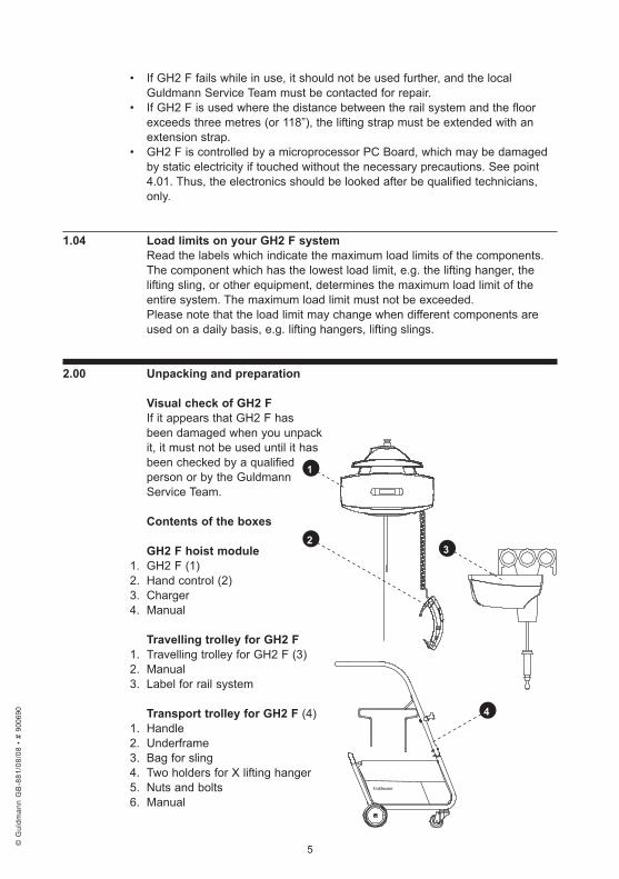
Visual .check .of .GH2 .FIf it appears that GH2 F has been damaged when you unpack it, it must not be used until it has been checked by a qualified person or by the Guldmann Service Team.
Contents .of .the .boxes .
GH2 .F .hoist .module1. GH2 F (1)2. Hand control (2)3. Charger4. Manual
Travelling .trolley .for .GH2 .F1. Travelling trolley for GH2 F (3)2. Manual3. Label for rail system
Transport .trolley .for .GH2 .F .(4)1. Handle2. Underframe3. Bag for sling4. Two holders for X lifting hanger5. Nuts and bolts6. Manual
3
1
2
4
© G
uldm
ann
GB
-881
/08/
08 •
# 9
0069
0
© G
uldm
ann
GB
-881
/08/
08 •
# 9
0069
0
© G
uldm
ann
GB
-881
/08/
08 •
# 9
0069
0
© G
uldm
ann
GB
-881
/08/
08 •
# 9
0069
0
6
2 .01 . Mounting .the .lifting .hanger .before .use .
Lifting .hangers .made .by .other .manufacturers .Guldmann shall not be liable for faults or accidents that occur as a result of using a lifting hanger made by other manufacturers.
If you are in doubt about the choice or use of lifting hanger, please contact your supplier.
Strap .with .snap .hookUse lifting hanger type 21X87 or the X lifting hanger type 21387 when using GH2 F with a snap hook.
The snap hook is sewn onto the strap and cannot be removed. Please noteBath chairs, bath stretchers, and horizontal stretchers must be attached to the snap hook.
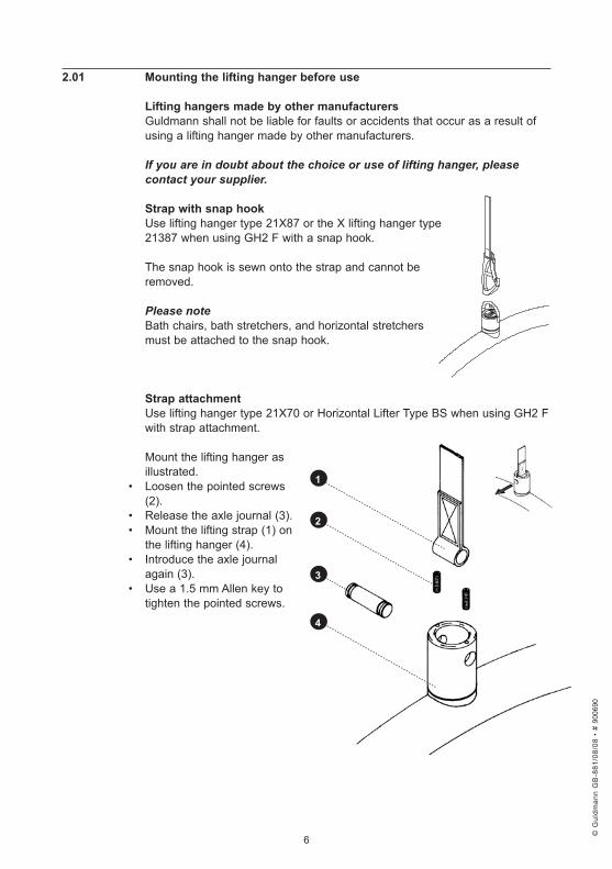
Strap .attachmentUse lifting hanger type 21X70 or Horizontal Lifter Type BS when using GH2 F with strap attachment.
Mount the lifting hanger as illustrated.
• Loosen the pointed screws (2).
• Release the axle journal (3).• Mount the lifting strap (1) on
the lifting hanger (4).• Introduce the axle journal
again (3).• Use a 1.5 mm Allen key to
tighten the pointed screws.
1
2
3
4
© G
uldm
ann
GB
-881
/08/
08 •
# 9
0069
0
© G
uldm
ann
GB
-881
/08/
08 •
# 9
0069
0
© G
uldm
ann
GB
-881
/08/
08 •
# 9
0069
0
© G
uldm
ann
GB
-881
/08/
08 •
# 9
0069
0
7
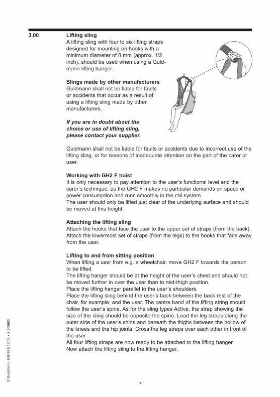
3 .00 . Lifting .slingA lifting sling with four to six lifting straps designed for mounting on hooks with a minimum diameter of 8 mm (approx. 1/2 inch), should be used when using a Guld-mann lifting hanger. Slings .made .by .other .manufacturers .Guldmann shall not be liable for faults or accidents that occur as a result of using a lifting sling made by other manufacturers.
If you are in doubt about the choice or use of lifting sling, please contact your supplier.
Guldmann shall not be liable for faults or accidents due to incorrect use of the lifting sling, or for reasons of inadequate attention on the part of the carer or user.
Working .with .GH2 .F .hoistIt is only necessary to pay attention to the user’s functional level and the carer’s technique, as the GH2 F makes no particular demands on space or power consumption and runs smoothly in the rail system. The user should only be lifted just clear of the underlying surface and should be moved at this height.
Attaching .the .lifting .sling .Attach the hooks that face the user to the upper set of straps (from the back). Attach the lowermost set of straps (from the legs) to the hooks that face away from the user.
Lifting .to .and .from .sitting .positionWhen lifting a user from e.g. a wheelchair, move GH2 F towards the person to be lifted. The lifting hanger should be at the height of the user’s chest and should not be moved further in over the user than to mid-thigh position. Place the lifting hanger parallel to the user’s shoulders. Place the lifting sling behind the user’s back between the back rest of the chair, for example, and the user. The centre band of the lifting string should follow the user’s spine. As for the sling types Active, the strap showing the size of the sling should be opposite the spine. Lead the leg straps along the outer side of the user’s shins and beneath the thighs between the hollow of the knees and the hip joints. Cross the leg straps over each other in front of the user. All four lifting straps are now ready to be attached to the lifting hanger. Now attach the lifting sling to the lifting hanger.
© G
uldm
ann
GB
-881
/08/
08 •
# 9
0069
0
© G
uldm
ann
GB
-881
/08/
08 •
# 9
0069
0
© G
uldm
ann
GB
-881
/08/
08 •
# 9
0069
0
© G
uldm
ann
GB
-881
/08/
08 •
# 9
0069
0
8
Lifting .to .and .from .a .lying .position .in .bedPlace the lifting hanger centrally above the person to be lifted. Place the lifting hanger parallel to the user’s shoulders.Turn the user on to his/her side. The lifting high back sling should be placed so that its top is at the same height as the top of the user’s head. Lay the sling over the user so that the centre band follows the user’s spine. Turn the user on to his/her back and pull out the remaining part of the lifting sling. Place the leg straps beneath the user’s thighs and cross them over each other. All four lifting straps are now ready to be attached and the lifting sling can now be mounted on the lifting hanger. It is an advantage to elevate the head of the bed so that the user is sitting up.
3 .01 . Swing .kitA swing kit must not be used in conjunction with GH2 F.
4 .00 . Before .the .hoist .can .be .used .
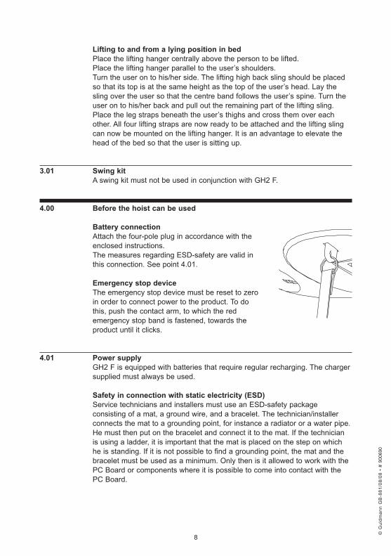
Battery .connection .Attach the four-pole plug in accordance with the enclosed instructions. The measures regarding ESD-safety are valid in this connection. See point 4.01.
Emergency .stop .deviceThe emergency stop device must be reset to zero in order to connect power to the product. To do this, push the contact arm, to which the red emergency stop band is fastened, towards the product until it clicks.
4 .01 . Power .supply .GH2 F is equipped with batteries that require regular recharging. The charger supplied must always be used.
Safety .in .connection .with .static .electricity .(ESD) .Service technicians and installers must use an ESD-safety package consisting of a mat, a ground wire, and a bracelet. The technician/installer connects the mat to a grounding point, for instance a radiator or a water pipe. He must then put on the bracelet and connect it to the mat. If the technician is using a ladder, it is important that the mat is placed on the step on which he is standing. If it is not possible to find a grounding point, the mat and the bracelet must be used as a minimum. Only then is it allowed to work with the PC Board or components where it is possible to come into contact with the PC Board.
© G
uldm
ann
GB
-881
/08/
08 •
# 9
0069
0
© G
uldm
ann
GB
-881
/08/
08 •
# 9
0069
0
© G
uldm
ann
GB
-881
/08/
08 •
# 9
0069
0
© G
uldm
ann
GB
-881
/08/
08 •
# 9
0069
0
9
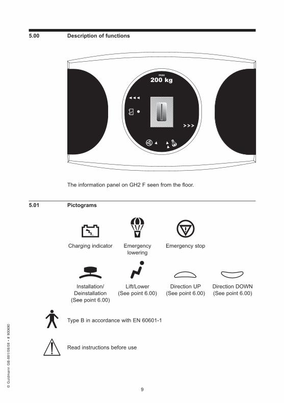
5 .00 . Description .of .functions
The information panel on GH2 F seen from the floor.
5 .01 . Pictograms
Charging indicator Emergency Emergency stop lowering
Installation/ Lift/Lower Direction UP Direction DOWN Deinstallation (See point 6.00) (See point 6.00) (See point 6.00) (See point 6.00)
Type B in accordance with EN 60601-1
Read instructions before use
© G
uldm
ann
GB
-881
/08/
08 •
# 9
0069
0
© G
uldm
ann
GB
-881
/08/
08 •
# 9
0069
0
© G
uldm
ann
GB
-881
/08/
08 •
# 9
0069
0
© G
uldm
ann
GB
-881
/08/
08 •
# 9
0069
0
10
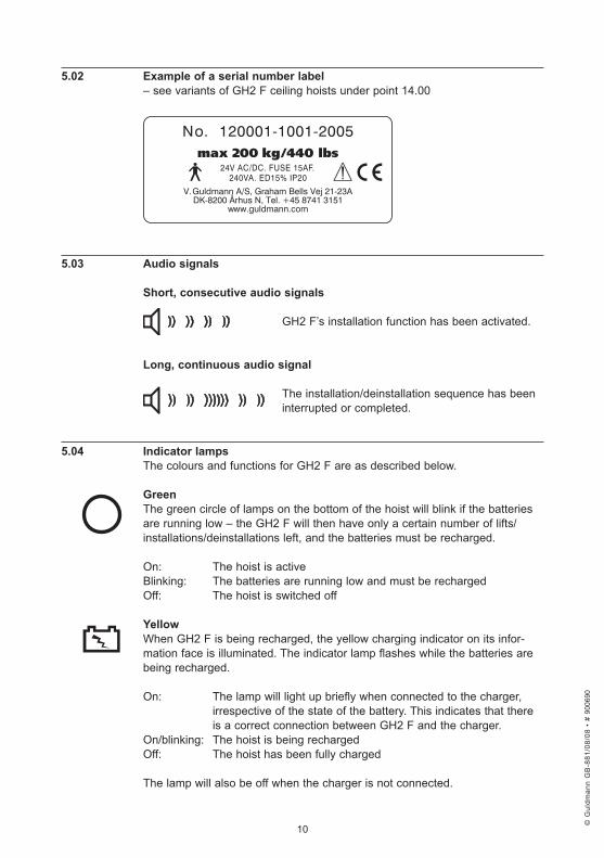
5 .02 . Example .of .a .serial .number .label– see variants of GH2 F ceiling hoists under point 14.00
5 .03 . Audio .signals
Short, .consecutive .audio .signals GH2 F’s installation function has been activated.
Long, .continuous .audio .signal
The installation/deinstallation sequence has been interrupted or completed.
5 .04 . Indicator .lampsThe colours and functions for GH2 F are as described below. Green .The green circle of lamps on the bottom of the hoist will blink if the batteries are running low – the GH2 F will then have only a certain number of lifts/installations/deinstallations left, and the batteries must be recharged.
On: The hoist is active Blinking: The batteries are running low and must be recharged Off: The hoist is switched off Yellow .When GH2 F is being recharged, the yellow charging indicator on its infor-mation face is illuminated. The indicator lamp flashes while the batteries are being recharged.
On: The lamp will light up briefly when connected to the charger, irrespective of the state of the battery. This indicates that there is a correct connection between GH2 F and the charger.On/blinking: The hoist is being recharged Off: The hoist has been fully charged
The lamp will also be off when the charger is not connected.
© G
uldm
ann
GB
-881
/08/
08 •
# 9
0069
0
© G
uldm
ann
GB
-881
/08/
08 •
# 9
0069
0
© G
uldm
ann
GB
-881
/08/
08 •
# 9
0069
0
© G
uldm
ann
GB
-881
/08/
08 •
# 9
0069
0
11
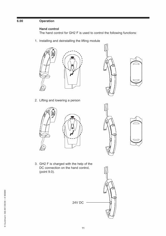
6 .00 . Operation
Hand .controlThe hand control for GH2 F is used to control the following functions:
1. Installing and deinstalling the lifting module
2. Lifting and lowering a person
3. GH2 F is charged with the help of the DC connection on the hand control, (point 9.0).
24V DC
© G
uldm
ann
GB
-881
/08/
08 •
# 9
0069
0
© G
uldm
ann
GB
-881
/08/
08 •
# 9
0069
0
© G
uldm
ann
GB
-881
/08/
08 •
# 9
0069
0
© G
uldm
ann
GB
-881
/08/
08 •
# 9
0069
0
12
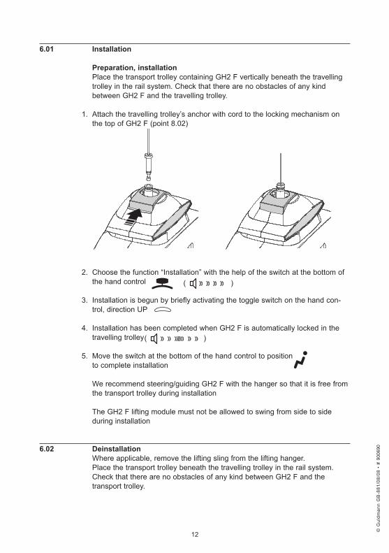
6 .01 . Installation
Preparation, .installationPlace the transport trolley containing GH2 F vertically beneath the travelling trolley in the rail system. Check that there are no obstacles of any kind between GH2 F and the travelling trolley.
1. Attach the travelling trolley’s anchor with cord to the locking mechanism on the top of GH2 F (point 8.02)
2. Choose the function “Installation” with the help of the switch at the bottom of the hand control
3. Installation is begun by briefly activating the toggle switch on the hand con-
trol, direction UP
4. Installation has been completed when GH2 F is automatically locked in the travelling trolley
5. Move the switch at the bottom of the hand control to position
to complete installation
We recommend steering/guiding GH2 F with the hanger so that it is free from the transport trolley during installation
The GH2 F lifting module must not be allowed to swing from side to side during installation
6 .02 . DeinstallationWhere applicable, remove the lifting sling from the lifting hanger.Place the transport trolley beneath the travelling trolley in the rail system.Check that there are no obstacles of any kind between GH2 F and the transport trolley.
( )
( )
© G
uldm
ann
GB
-881
/08/
08 •
# 9
0069
0
© G
uldm
ann
GB
-881
/08/
08 •
# 9
0069
0
© G
uldm
ann
GB
-881
/08/
08 •
# 9
0069
0
© G
uldm
ann
GB
-881
/08/
08 •
# 9
0069
0
13
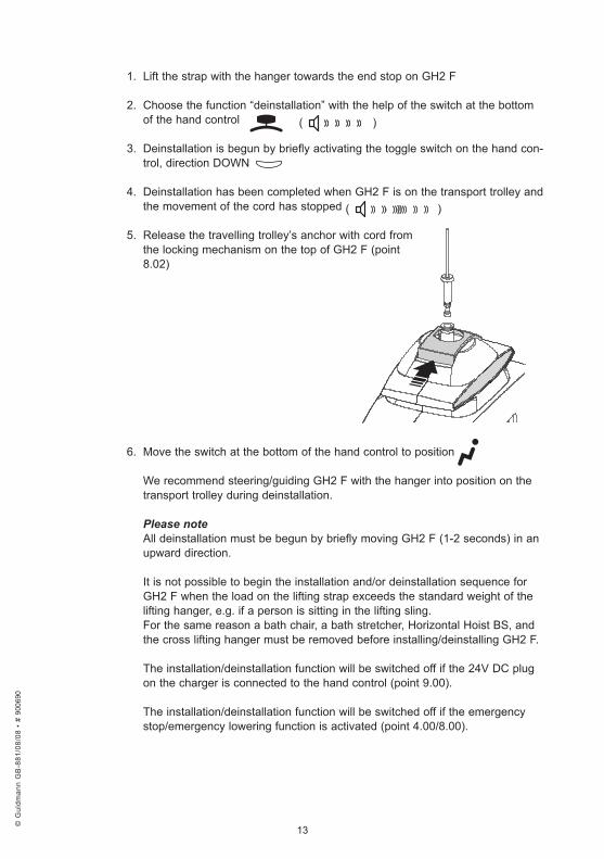
1. Lift the strap with the hanger towards the end stop on GH2 F
2. Choose the function “deinstallation” with the help of the switch at the bottom of the hand control
3. Deinstallation is begun by briefly activating the toggle switch on the hand con-
trol, direction DOWN
4. Deinstallation has been completed when GH2 F is on the transport trolley and the movement of the cord has stopped
5. Release the travelling trolley’s anchor with cord from the locking mechanism on the top of GH2 F (point 8.02)
6. Move the switch at the bottom of the hand control to position
We recommend steering/guiding GH2 F with the hanger into position on the transport trolley during deinstallation.
Please note All deinstallation must be begun by briefly moving GH2 F (1-2 seconds) in an upward direction.
It is not possible to begin the installation and/or deinstallation sequence for GH2 F when the load on the lifting strap exceeds the standard weight of the lifting hanger, e.g. if a person is sitting in the lifting sling.For the same reason a bath chair, a bath stretcher, Horizontal Hoist BS, and the cross lifting hanger must be removed before installing/deinstalling GH2 F.
The installation/deinstallation function will be switched off if the 24V DC plug on the charger is connected to the hand control (point 9.00).
The installation/deinstallation function will be switched off if the emergency stop/emergency lowering function is activated (point 4.00/8.00).
( )
( )
© G
uldm
ann
GB
-881
/08/
08 •
# 9
0069
0
© G
uldm
ann
GB
-881
/08/
08 •
# 9
0069
0
© G
uldm
ann
GB
-881
/08/
08 •
# 9
0069
0
© G
uldm
ann
GB
-881
/08/
08 •
# 9
0069
0
14
6 .03 . Lock, .Travelling .trolley .for .GH2 .FThe locking mechanism/clutch on the travelling trolley is automatic and changes between a locked and an unlocked state. It changes states each time it is activated.
Avoid unnecessary contact with the lock.
Contact the Guldmann Service Team if it appears that the lock may be damaged.
6 .04 . Lifting .and .lowering
1. Check that the switch at the bottom of the hand control is placed in position
2. Lifting/lowering of a person is begun by activating the toggle switch, direction UP or direction DOWN
Pressing a button on the hand control automatically switches on the GH2 F hoist. The GH2 F hoist will automatically switch off after approximately ten minutes when not in use.
NoteThere must be a load on GH2 F corresponding to the weight of a Guldmann lifting hanger before the lowering function will work.
The lifting/lowering function will be switched off if the 24V DC plug of the charger is connected to the hand control (point 9.00).
The lifting/lowering function will be switched off if the emergency stop/emer-gency lowering system is activated (point 4.00/8.00).
7 .00 . Transport/running .in .the .rail .systemThe carer must push GH2 F manually in the rail system.
NoteGH2 F must not be exposed to cold or heat shock, so a cold lifting module should never be taken into a warm bathroom or similar.
© G
uldm
ann
GB
-881
/08/
08 •
# 9
0069
0
© G
uldm
ann
GB
-881
/08/
08 •
# 9
0069
0
© G
uldm
ann
GB
-881
/08/
08 •
# 9
0069
0
© G
uldm
ann
GB
-881
/08/
08 •
# 9
0069
0
15
8 .00 . Safety .functions
WARNING!The emergency stop and emergency lowering functions should be used only in an emergency. If, contrary to expectation, it becomes necessary to use the emergency functions, the fault must be located and remedied before using GH2 F again.Please contact your supplier.
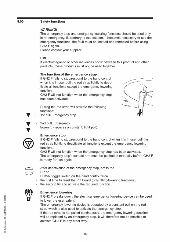
EMCIf electromagnetic or other influences occur between this product and other products, these products must not be used together. The .function .of .the .emergency .strapIf GH2 F fails to stop/respond to the hand control when it is in use, pull the red strap lightly to deac-tivate all functions except the emergency lowering function. GH2 F will not function when the emergency stop has been activated.
Pulling the red strap will activate the following functions:
• 1st pull: Emergency stop
• 2nd pull: Emergency lowering (requires a constant, light pull).
Emergency .stopIf GH2 F fails to stop/respond to the hand control when it is in use, pull the red strap lightly to deactivate all functions except the emergency lowering function.GH2 F will not function when the emergency stop has been activated.The emergency stop’s contact arm must be pushed in manually before GH2 F is ready for use again.
After deactivation of the emergency stop, press the UP or DOWN toggle switch on the hand control twice.
• the first time to reset the PC Board (only lifting/lowering functions),• the second time to activate the required function.
Emergency .loweringIf GH2 F breaks down, the electrical emergency lowering device can be used to lower the user safely.The emergency lowering device is operated by a constant pull on the red strap which is also used to activate the emergency stop.If the red strap is not pulled continuously, the emergency lowering function will be replaced by an emergency stop. It will therefore not be possible to activate GH2 F in any other way.
© G
uldm
ann
GB
-881
/08/
08 •
# 9
0069
0
© G
uldm
ann
GB
-881
/08/
08 •
# 9
0069
0
© G
uldm
ann
GB
-881
/08/
08 •
# 9
0069
0
© G
uldm
ann
GB
-881
/08/
08 •
# 9
0069
0
16
8 .01 . Safety .functions, .installation/deinstallation
Installation/deinstallationThe installation/deinstallation sequence can be interrupted with the hand control at any time:
1. Press (again) UP to interrupt the installation/deinstallation sequence
2. Press (again) DOWN to interrupt the installation/deinstallation sequence
3. Move the switch at the bottom of the hand control back to position to interrupt the installation/deinstallation sequence The installation sequence will be automatically interrupted if GH2 F meets an obstacle/resistance (≥ 5-10 kg) while being moved to the travelling trolley in the rail system, for instance when blocked by a foreign body during installation. If this happens, GH2 F will stop briefly and then move freely in the direction of the travelling trolley.
Resuming .installation/deinstallationWhen the obstacle has been removed, the installation or deinstallation sequence can be resumed, cf. point 6.01, “installation, step 3”.
NoteThe installation/deinstallation sequence can also be interrupted with the help of the emergency stop/emergency lowering function, or if the 24V DC plug on the charger is connected to the hand control (point 9.0).
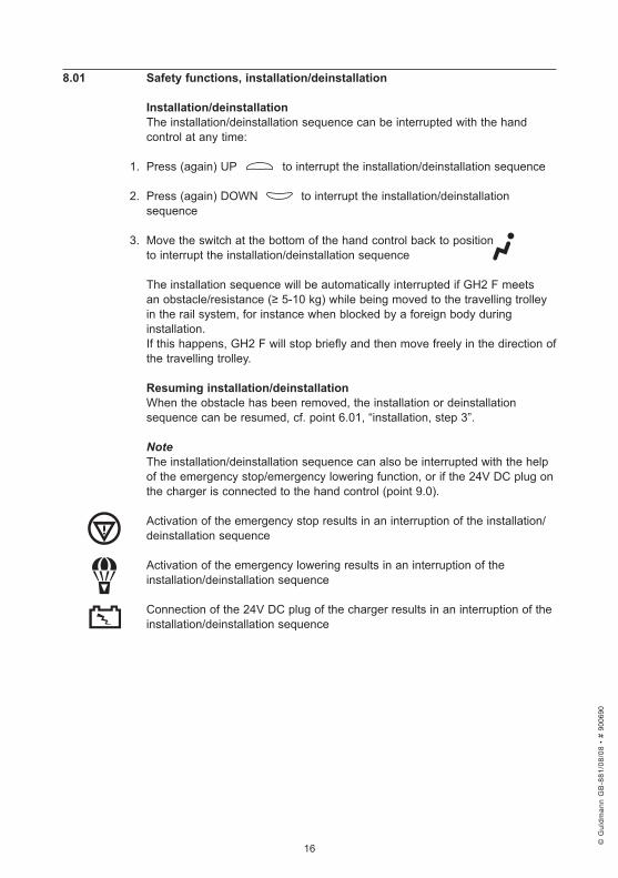
Activation of the emergency stop results in an interruption of the installation/deinstallation sequence
Activation of the emergency lowering results in an interruption of the installation/deinstallation sequence
Connection of the 24V DC plug of the charger results in an interruption of the installation/deinstallation sequence
© G
uldm
ann
GB
-881
/08/
08 •
# 9
0069
0
© G
uldm
ann
GB
-881
/08/
08 •
# 9
0069
0
© G
uldm
ann
GB
-881
/08/
08 •
# 9
0069
0
© G
uldm
ann
GB
-881
/08/
08 •
# 9
0069
0
17
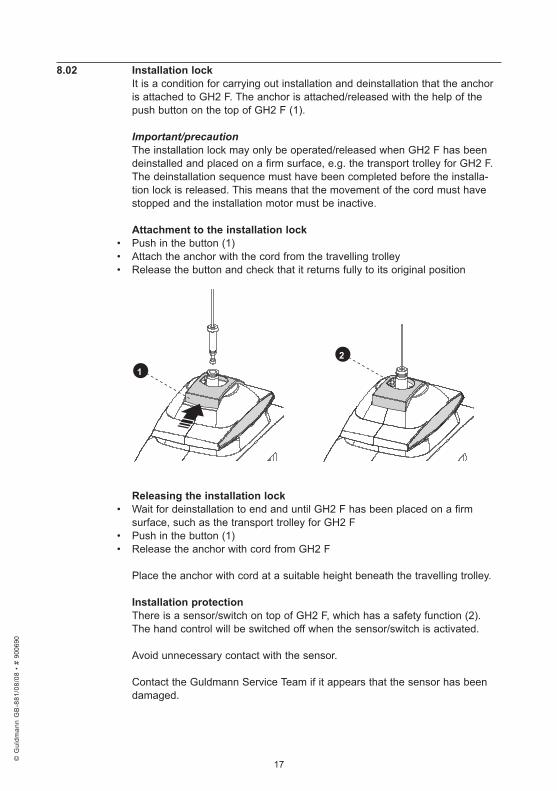
8 .02 . Installation .lockIt is a condition for carrying out installation and deinstallation that the anchor is attached to GH2 F. The anchor is attached/released with the help of the push button on the top of GH2 F (1).
Important/precautionThe installation lock may only be operated/released when GH2 F has been deinstalled and placed on a firm surface, e.g. the transport trolley for GH2 F.The deinstallation sequence must have been completed before the installa-tion lock is released. This means that the movement of the cord must have stopped and the installation motor must be inactive.
Attachment .to .the .installation .lock• Push in the button (1) • Attach the anchor with the cord from the travelling trolley• Release the button and check that it returns fully to its original position
Releasing .the .installation .lock .• Wait for deinstallation to end and until GH2 F has been placed on a firm
surface, such as the transport trolley for GH2 F• Push in the button (1)• Release the anchor with cord from GH2 F
Place the anchor with cord at a suitable height beneath the travelling trolley.
Installation .protectionThere is a sensor/switch on top of GH2 F, which has a safety function (2). The hand control will be switched off when the sensor/switch is activated.
Avoid unnecessary contact with the sensor.
Contact the Guldmann Service Team if it appears that the sensor has been damaged.
1
2
© G
uldm
ann
GB
-881
/08/
08 •
# 9
0069
0
© G
uldm
ann
GB
-881
/08/
08 •
# 9
0069
0
© G
uldm
ann
GB
-881
/08/
08 •
# 9
0069
0
© G
uldm
ann
GB
-881
/08/
08 •
# 9
0069
0
18
8 .03 . Explanation .of .labels . Type .B .In accordance with EN 60601-1. Warning .Before use, cleaning, and service, read the user’s instructions and technical documentation.
Description .of .strap .safety .device, .lifting/lowering .function .Overloading the hoist, pulling the strap crookedly, or if the strap is twisted, the strap safety device will be activated, and GH2 F will be deactivated. If the yellow mark on the strap is visible, do not lift with maximum load.
9 .00 . Charging/connection
Recharge the GH2 F hoist with the accompanying charging unit.
Recharge GH2 F every night, or when not in use. This is the best way to maintain the batteries and ensure as long a lifetime as possible.
A pre-installed male plug on the connection side, appropriate for the mains system in the country in question, will protect the charger against incorrect use.
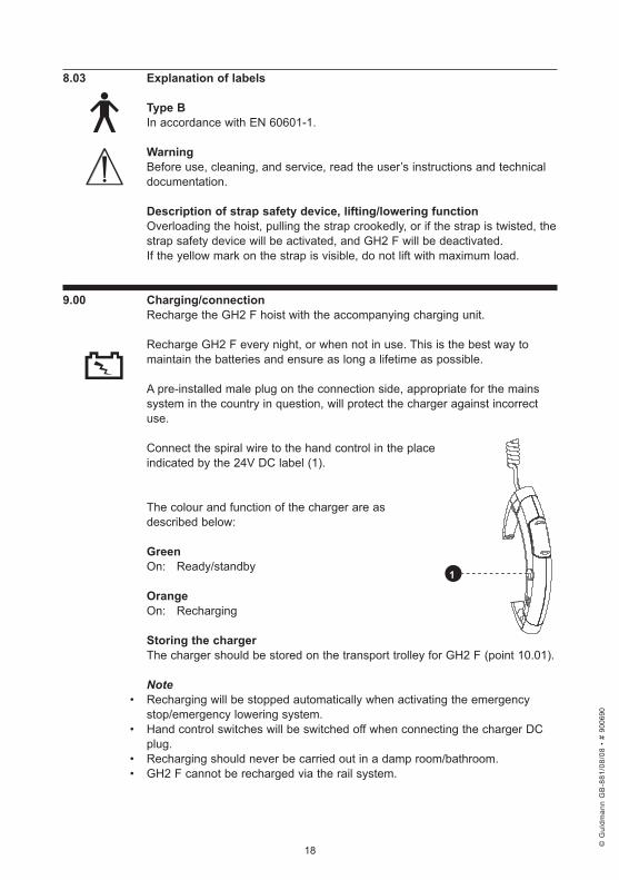
Connect the spiral wire to the hand control in the place indicated by the 24V DC label (1).
The colour and function of the charger are as described below:
GreenOn: Ready/standby
OrangeOn: Recharging
Storing .the .chargerThe charger should be stored on the transport trolley for GH2 F (point 10.01).
Note• Recharging will be stopped automatically when activating the emergency
stop/emergency lowering system.• Hand control switches will be switched off when connecting the charger DC
plug.• Recharging should never be carried out in a damp room/bathroom.• GH2 F cannot be recharged via the rail system.
1
© G
uldm
ann
GB
-881
/08/
08 •
# 9
0069
0
© G
uldm
ann
GB
-881
/08/
08 •
# 9
0069
0
© G
uldm
ann
GB
-881
/08/
08 •
# 9
0069
0
© G
uldm
ann
GB
-881
/08/
08 •
# 9
0069
0
19
10 .00 . Accessories .
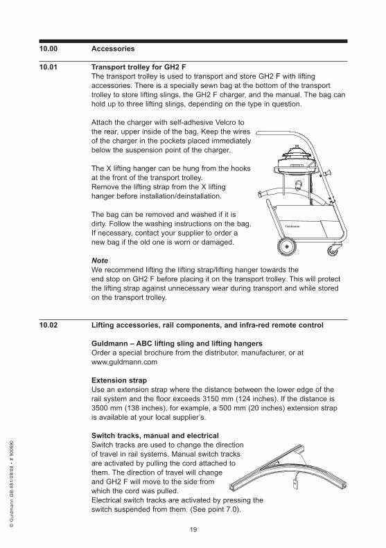
10 .01 . Transport .trolley .for .GH2 .FThe transport trolley is used to transport and store GH2 F with lifting accessories. There is a specially sewn bag at the bottom of the transport trolley to store lifting slings, the GH2 F charger, and the manual. The bag can hold up to three lifting slings, depending on the type in question.
Attach the charger with self-adhesive Velcro to the rear, upper inside of the bag. Keep the wires of the charger in the pockets placed immediately below the suspension point of the charger.
The X lifting hanger can be hung from the hooks at the front of the transport trolley. Remove the lifting strap from the X lifting hanger before installation/deinstallation.
The bag can be removed and washed if it is dirty. Follow the washing instructions on the bag. If necessary, contact your supplier to order a new bag if the old one is worn or damaged.
NoteWe recommend lifting the lifting strap/lifting hanger towards the end stop on GH2 F before placing it on the transport trolley. This will protect the lifting strap against unnecessary wear during transport and while stored on the transport trolley.
10 .02 . Lifting .accessories, .rail .components, .and .infra-red .remote .control
Guldmann .– .ABC .lifting .sling .and .lifting .hangers .Order a special brochure from the distributor, manufacturer, or at www.guldmann.com
Extension .strap .Use an extension strap where the distance between the lower edge of the rail system and the floor exceeds 3150 mm (124 inches). If the distance is 3500 mm (138 inches), for example, a 500 mm (20 inches) extension strap is available at your local supplier’s.
Switch .tracks, .manual .and .electricalSwitch tracks are used to change the direction of travel in rail systems. Manual switch tracks are activated by pulling the cord attached to them. The direction of travel will change and GH2 F will move to the side from which the cord was pulled. Electrical switch tracks are activated by pressing the switch suspended from them. (See point 7.0).
© G
uldm
ann
GB
-881
/08/
08 •
# 9
0069
0
© G
uldm
ann
GB
-881
/08/
08 •
# 9
0069
0
© G
uldm
ann
GB
-881
/08/
08 •
# 9
0069
0
© G
uldm
ann
GB
-881
/08/
08 •
# 9
0069
0
20
Safety .The product is mechanically protected against derailment and jamming.
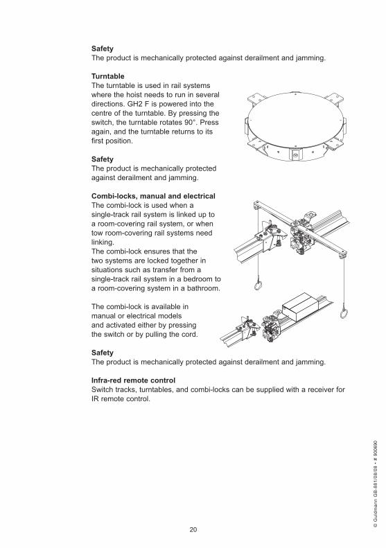
Turntable .The turntable is used in rail systems where the hoist needs to run in several directions. GH2 F is powered into the centre of the turntable. By pressing the switch, the turntable rotates 90°. Press again, and the turntable returns to its first position.
Safety .The product is mechanically protected against derailment and jamming.
Combi-locks, .manual .and .electricalThe combi-lock is used when a single-track rail system is linked up to a room-covering rail system, or when tow room-covering rail systems need linking. The combi-lock ensures that the two systems are locked together in situations such as transfer from a single-track rail system in a bedroom to a room-covering system in a bathroom.
The combi-lock is available in manual or electrical models and activated either by pressingthe switch or by pulling the cord.
Safety .The product is mechanically protected against derailment and jamming.
Infra-red .remote .controlSwitch tracks, turntables, and combi-locks can be supplied with a receiver for IR remote control.
© G
uldm
ann
GB
-881
/08/
08 •
# 9
0069
0
© G
uldm
ann
GB
-881
/08/
08 •
# 9
0069
0
© G
uldm
ann
GB
-881
/08/
08 •
# 9
0069
0
© G
uldm
ann
GB
-881
/08/
08 •
# 9
0069
0
21
11 .00 . Transport .Guldmann recommends that GH2 F is always transported and stored in its original packaging.
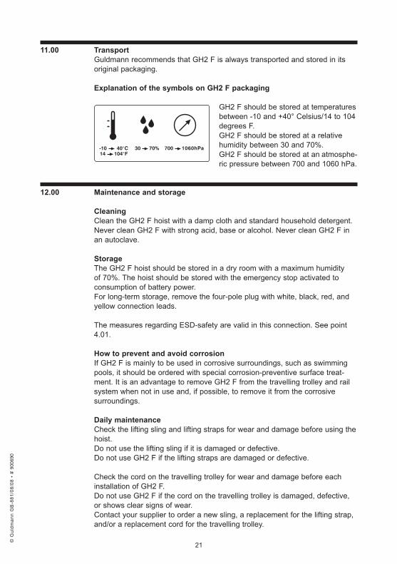
Explanation .of .the .symbols .on .GH2 .F .packaging .
GH2 F should be stored at temperatures between -10 and +40° Celsius/14 to 104 degrees F.GH2 F should be stored at a relative humidity between 30 and 70%.GH2 F should be stored at an atmosphe-ric pressure between 700 and 1060 hPa.
12 .00 . Maintenance .and .storage
CleaningClean the GH2 F hoist with a damp cloth and standard household detergent.Never clean GH2 F with strong acid, base or alcohol. Never clean GH2 F in an autoclave.
StorageThe GH2 F hoist should be stored in a dry room with a maximum humidity of 70%. The hoist should be stored with the emergency stop activated to consumption of battery power.For long-term storage, remove the four-pole plug with white, black, red, and yellow connection leads.
The measures regarding ESD-safety are valid in this connection. See point 4.01.
How .to .prevent .and .avoid .corrosion .If GH2 F is mainly to be used in corrosive surroundings, such as swimming pools, it should be ordered with special corrosion-preventive surface treat-ment. It is an advantage to remove GH2 F from the travelling trolley and rail system when not in use and, if possible, to remove it from the corrosive surroundings.
Daily .maintenance .Check the lifting sling and lifting straps for wear and damage before using the hoist.Do not use the lifting sling if it is damaged or defective.Do not use GH2 F if the lifting straps are damaged or defective.
Check the cord on the travelling trolley for wear and damage before each installation of GH2 F.Do not use GH2 F if the cord on the travelling trolley is damaged, defective, or shows clear signs of wear.Contact your supplier to order a new sling, a replacement for the lifting strap, and/or a replacement cord for the travelling trolley.
700 1060hPa-10 40°C14 104°F
30 70%
© G
uldm
ann
GB
-881
/08/
08 •
# 9
0069
0
© G
uldm
ann
GB
-881
/08/
08 •
# 9
0069
0
© G
uldm
ann
GB
-881
/08/
08 •
# 9
0069
0
© G
uldm
ann
GB
-881
/08/
08 •
# 9
0069
0
22
Lifting straps and cords for the travelling trolley must be replaced by the Guldmann Service Team or by a qualified service fitter in accordance with Guldmann’s instructions.
Disposal .of .GH2 .F, .including .batteries .Local and national regulations for environmentally responsible recycling must be observed. Batteries should always be taken to approved recycling points.
13 .00 . Service .and .lifetime .
Lifetime .GH2 F has an expected lifetime of ten years provided that the service inspections mentioned under point 13.01 are observed.
Replacing .components .Batteries, printed circuit boards, lifting straps, and the locking and winding mechanism on the travelling trolley must be replaced by the Guldmann Service Team or by a qualified service fitter in accordance with Guldmann’s instructions.
13 .01 . Service .inspectionAccording to the international standard EN/ISO 10535 “Hoist for the transfer of disabled persons - Requirements and test methods” a safety inspection of the GH2 F must be performed at least one a year.
GH2 F and the Travelling trolley for GH2 F must be inspected by a qualified service fitter or by the Guldmann Service Team. Guldmann offers a service agreement for GH2 F in connection with these inspections.The service inspection includes a written report specifying what has been inspected and replaced. Worn or defective components must be replaced by new components from Guldmann. Spare parts drawings and lists can be ordered from the manufacturer or distributor.
13 .02 . Service .inspection, .GH2 .F
1 . . Visual .control .of .the .hoist .• Check for wear, irregularities, or other types of damage to the hoist.
2 . . Testing .the .product .as .in .normal .use .• Check all hoist functions with and without loads • Check that the emergency stop functions • Check that the emergency lowering device functions• Check that the green indicator lamps light up when the hoist is activated • Check that the yellow charging indicator lights up when the hoist is being
recharged• Check that the functions of the hand control are switched off when the sensor
on top of GH2 F is activated
© G
uldm
ann
GB
-881
/08/
08 •
# 9
0069
0
© G
uldm
ann
GB
-881
/08/
08 •
# 9
0069
0
© G
uldm
ann
GB
-881
/08/
08 •
# 9
0069
0
© G
uldm
ann
GB
-881
/08/
08 •
# 9
0069
0
23
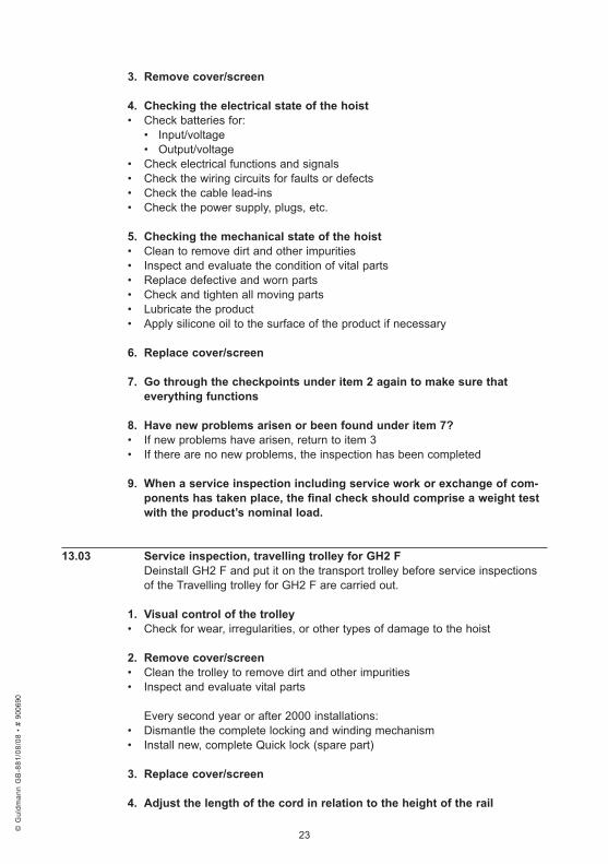
3 . . Remove .cover/screen .
4 . . Checking .the .electrical .state .of .the .hoist .• Check batteries for: • Input/voltage • Output/voltage • Check electrical functions and signals • Check the wiring circuits for faults or defects • Check the cable lead-ins • Check the power supply, plugs, etc.
5 . . Checking .the .mechanical .state .of .the .hoist .• Clean to remove dirt and other impurities • Inspect and evaluate the condition of vital parts • Replace defective and worn parts• Check and tighten all moving parts• Lubricate the product• Apply silicone oil to the surface of the product if necessary
6 . . Replace .cover/screen .
7 . . Go .through .the .checkpoints .under .item .2 .again .to .make .sure .that . .everything .functions .
8 . . Have .new .problems .arisen .or .been .found .under .item .7? .• If new problems have arisen, return to item 3 • If there are no new problems, the inspection has been completed
9 . . When .a .service .inspection .including .service .work .or .exchange .of .com-ponents .has .taken .place, .the .final .check .should .comprise .a .weight .test .with .the .product’s .nominal .load .
13 .03 . Service .inspection, .travelling .trolley .for .GH2 .FDeinstall GH2 F and put it on the transport trolley before service inspections of the Travelling trolley for GH2 F are carried out.
1 . . Visual .control .of .the .trolley• Check for wear, irregularities, or other types of damage to the hoist
2 . . Remove .cover/screen .• Clean the trolley to remove dirt and other impurities• Inspect and evaluate vital parts
Every second year or after 2000 installations:• Dismantle the complete locking and winding mechanism• Install new, complete Quick lock (spare part)
3 . . Replace .cover/screen .
4 . . Adjust .the .length .of .the .cord .in .relation .to .the .height .of .the .rail
© G
uldm
ann
GB
-881
/08/
08 •
# 9
0069
0
© G
uldm
ann
GB
-881
/08/
08 •
# 9
0069
0
© G
uldm
ann
GB
-881
/08/
08 •
# 9
0069
0
© G
uldm
ann
GB
-881
/08/
08 •
# 9
0069
0

24
5 . . Carry .out .installation .and .deinstallation .of .GH2 .F• Check all product functions 6 . . Have .new .problems .arisen .or .been .found .under .item .5? .• If new problems have arisen, return to item 2 • If there are no new problems, the service inspection has been completed
7 . . When .a .service .inspection .including .service .work .or .exchange .of .com-ponents .has .taken .place, .the .final .check .should .comprise .a .weight .test .with .the .product’s .nominal .load .
13 .04 . Trouble-shootingGH2 F lifting/lowering functions fail to respond when the hand control’s up/down keys are pressed.
• Check that the emergency stop/emergency lowering device have not been activated
• Check that power is supplied to the hoist • Check that the charger is not connected to the hand control
Is .the .product .installed .in .the .travelling .trolley/rail .system?If NO
• Contact the Guldmann Service Team The hand control may be defective
If YES• Contact the Guldmann Service Team GH2 F may have been incorrectly installed
The .green .lamp .on .GH2 .F .blinks .after .it .has .been .connected .to . .the .charger
1. Check that the yellow charging indicator lights up when GH2 F is connected to the charger
2. Check that the charger is correctly connected to the hand control3. Check that the power supply is switched on4. Contact the Guldmann Service Team
13 .05 . FAQ’sCan GH2 F be installed/deinstalled while a person is sitting in the lifting sling?No – GH2 F measures the load on the lifting strap before installation/ deinstallation. If the load exceeds the weight of the lifting hanger, the sequence for installation/deinstallation cannot be activated.
Find more FAQ’s at www.guldmann.com
© G
uldm
ann
GB
-881
/08/
08 •
# 9
0069
0
© G
uldm
ann
GB
-881
/08/
08 •
# 9
0069
0
© G
uldm
ann
GB
-881
/08/
08 •
# 9
0069
0
© G
uldm
ann
GB
-881
/08/
08 •
# 9
0069
0
25
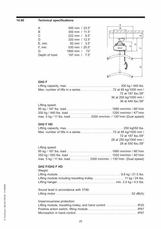
14 .00 . Technical .specifications
A 595 mm / 23.5” B 300 mm / 11.5”C 222 mm / 8.5”D 320 mm / 12.5”E, min. 82 mm / 3.5”F, min. 530 mm / 20.5”G 1850 mm / 73”Depth of hoist 197 mm / 7.5”
GH2 .FLifting capacity, max. . . . . . . . . . . . . . . . . . . . . . . . . . . . . . . 200 kg / 440 lbs.Max. number of lifts in a series . . . . . . . . . . . . . . . . . . .72 at 85 kg/1000 mm / 72 at 187 lbs./39” 36 at 200 kg/1000 mm / 36 at 440 lbs./39”Lifting speed:85 kg / 187 lbs. load . . . . . . . . . . . . . . . . . . . . . . . . . . 1680 mm/min / 66”/min200 kg / 440 lbs. load . . . . . . . . . . . . . . . . . . . . . . . . . 1200 mm/min / 47”/minmax. 5 kg / 11 lbs. load . . . . . . . . . . . .3300 mm/min. / 130”/min (Dual speed)
GH2 .F .HDLifting capacity, max. . . . . . . . . . . . . . . . . . . . . . . . . . . . . . . . . . 250 kg550 lbs.Max. number of lifts in a series . . . . . . . . . . . . . . . . . . .72 at 85 kg/1000 mm / 72 at 187 lbs./39” 28 at 250 kg/1000 mm / 28 at 550 lbs./39”Lifting speed:85 kg / 187 lbs. load . . . . . . . . . . . . . . . . . . . . . . . . . . 1680 mm/min / 66”/min250 kg / 550 lbs. load . . . . . . . . . . . . . . . . . . . . . . . . . 1020 mm/min / 40”/minmax. 5 kg / 11 lbs. load . . . . . . . . . . . 3300 mm/min. / 130”/min (Dual speed)
GH2 .F/GH2 .F .HDWeight:Lifting module. . . . . . . . . . . . . . . . . . . . . . . . . . . . . . . . . . . . . 9.8 kg / 21.5 lbs.Lifting module including travelling trolley . . . . . . . . . . . . . . . . . . 11 kg / 24 lbs. Lifting hanger . . . . . . . . . . . . . . . . . . . . . . . . . . . . . . . . . . min. 2.0 kg / 4.5 lbs.
Sound level in accordance with 3746:Lifting motor . . . . . . . . . . . . . . . . . . . . . . . . . . . . . . . . . . . . . . . . . . . . .52 dB(A)
Imperviousness protection:Lifting module, travelling trolley, and hand control . . . . . . . . . . . . . . . . . . IP20Positive action switch, lifting module . . . . . . . . . . . . . . . . . . . . . . . . . . . . . IP67Microswitch in hand control . . . . . . . . . . . . . . . . . . . . . . . . . . . . . . . . . . . . IP67
D
BA
C
FE
G
© G
uldm
ann
GB
-881
/08/
08 •
# 9
0069
0
© G
uldm
ann
GB
-881
/08/
08 •
# 9
0069
0
© G
uldm
ann
GB
-881
/08/
08 •
# 9
0069
0
© G
uldm
ann
GB
-881
/08/
08 •
# 9
0069
0
26
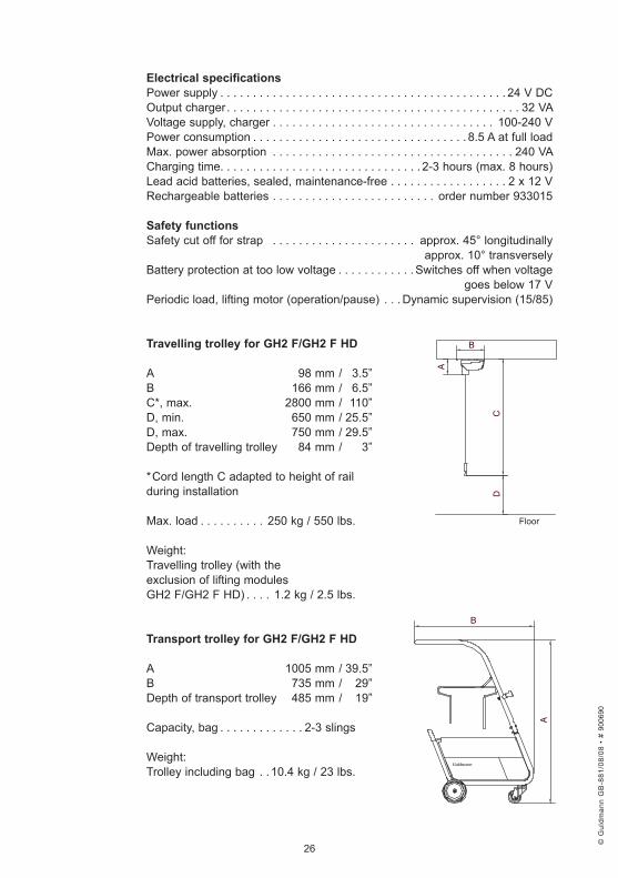
Electrical .specificationsPower supply . . . . . . . . . . . . . . . . . . . . . . . . . . . . . . . . . . . . . . . . . . . . 24 V DCOutput charger . . . . . . . . . . . . . . . . . . . . . . . . . . . . . . . . . . . . . . . . . . . . . 32 VAVoltage supply, charger . . . . . . . . . . . . . . . . . . . . . . . . . . . . . . . . . . 100-240 VPower consumption . . . . . . . . . . . . . . . . . . . . . . . . . . . . . . . . . 8.5 A at full loadMax. power absorption . . . . . . . . . . . . . . . . . . . . . . . . . . . . . . . . . . . . . 240 VACharging time. . . . . . . . . . . . . . . . . . . . . . . . . . . . . . . 2-3 hours (max. 8 hours)Lead acid batteries, sealed, maintenance-free . . . . . . . . . . . . . . . . . . 2 x 12 VRechargeable batteries . . . . . . . . . . . . . . . . . . . . . . . . . order number 933015
Safety .functionsSafety cut off for strap . . . . . . . . . . . . . . . . . . . . . . approx. 45° longitudinally approx. 10° transverselyBattery protection at too low voltage . . . . . . . . . . . . Switches off when voltage goes below 17 VPeriodic load, lifting motor (operation/pause) . . . Dynamic supervision (15/85)
Travelling .trolley .for .GH2 .F/GH2 .F .HD
A 98 mm / 3.5”B 166 mm / 6.5”C*, max. 2800 mm / 110”D, min. 650 mm / 25.5”D, max. 750 mm / 29.5”Depth of travelling trolley 84 mm / 3”
*Cord length C adapted to height of rail during installation
Max. load . . . . . . . . . . 250 kg / 550 lbs.
Weight:Travelling trolley (with the exclusion of lifting modules GH2 F/GH2 F HD) . . . . 1.2 kg / 2.5 lbs.
Transport .trolley .for .GH2 .F/GH2 .F .HD
A 1005 mm / 39.5”B 735 mm / 29”Depth of transport trolley 485 mm / 19”
Capacity, bag . . . . . . . . . . . . . 2-3 slings
Weight:Trolley including bag . .10.4 kg / 23 lbs.
B
A
D
A
B
C
Floor
© G
uldm
ann
GB
-881
/08/
08 •
# 9
0069
0
© G
uldm
ann
GB
-881
/08/
08 •
# 9
0069
0
© G
uldm
ann
GB
-881
/08/
08 •
# 9
0069
0
© G
uldm
ann
GB
-881
/08/
08 •
# 9
0069
0
27
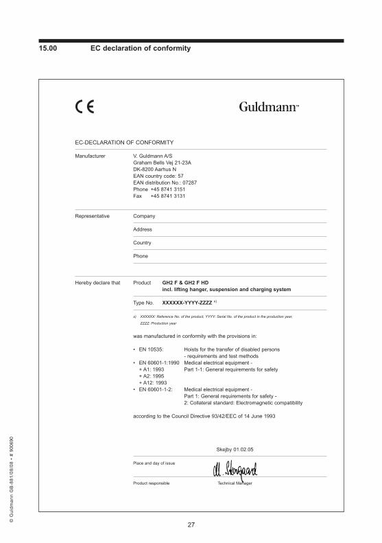
15 .00 . EC .declaration .of .conformity
EC-DECLARATION OF CONFORMITY
Manufacturer V. Guldmann A/SGraham Bells Vej 21-23ADK-8200 Aarhus NEAN country code: 57EAN distribution No.: 07287Phone +45 8741 3151Fax +45 8741 3131
Representative Company
Address
Country
Phone
Hereby declare that Product GH2 F & GH2 F HD incl. lifting hanger, suspension and charging system
Type No. XXXXXX-YYYY-ZZZZ x)
x) XXXXXX: Reference No. of the product, YYYY: Serial No. of the product in the production year,
ZZZZ: Production year
was manufactured in conformity with the provisions in:
• EN 10535: Hoists for the transfer of disabled persons - requirements and test methods
• EN 60601-1:1990 Medical electrical equipment - + A1: 1993 Part 1-1: General requirements for safety + A2: 1995 + A12: 1993• EN 60601-1-2: Medical electrical equipment -
Part 1: General requirements for safety - 2: Collateral standard: Electromagnetic compatibility
according to the Council Directive 93/42/EEC of 14 June 1993
Skejby 01.02.05
Place and day of issue
Product responsible Technical Manager
© G
uldm
ann
GB
-881
/08/
08 •
# 9
0069
0
© G
uldm
ann
GB
-881
/08/
08 •
# 9
0069
0
© G
uldm
ann
GB
-881
/08/
08 •
# 9
0069
0
© G
uldm
ann
GB
-881
/08/
08 •
# 9
0069
0
© G
uldm
ann
GB
-881
/08/
08 •
# 9
0069
0
V . .Guldmann .A/SHead Office:Graham Bells Vej 21-23ADK-8200 Århus NTlf. +45 8741 3100Fax +45 8741 [email protected]
© G
uldm
ann
GB
-881
/08/
08 •
# 9
0069
0