Embed Size (px)
Citation preview
I473
GB
01 1
9
3
1100
285
1
LOVATO ELECTRIC S.P.A.
24020 GORLE (BERGAMO) ITALIAVIA DON E. MAZZA, 12TEL. 035 4282111 E-mail [email protected] www.LovatoElectric.com
VLB3
GB VARIABLE SPEED DRIVES
Instruction manual
WARNING! – Carefully read the manual before the installation or use.– This equipment is to be installed by qualified personnel, complying to current standards, to avoid
damages or safety hazards. – Before any maintenance operation on the device, remove all the voltages from measuring and supply inputs and short-
circuit the CT input terminals.– The manufacturer cannot be held responsible for electrical safety in case of improper use of the equipment.– Products illustrated herein are subject to alteration and changes without prior notice. Technical data and descriptions in
the documentation are accurate, to the best of our knowledge, but no liabilities for errors, omissions or contingenciesarising there from are accepted.
– A circuit breaker must be included in the electrical installation of the building. It must be installed close by theequipment and within easy reach of the operator. It must be marked as the disconnecting device of the equipment: IEC /EN 61010-1 § 6.11.3.1.
– Clean the device with a soft dry cloth; do not use abrasives, liquid detergents or solvents.
ATTENZIONE!– Leggere attentamente il manuale prima dell’utilizzo e l’installazione.– Questi apparecchi devono essere installati da personale qualificato, nel rispetto delle vigenti normative
impiantistiche, allo scopo di evitare danni a persone o cose. – Prima di qualsiasi intervento sullo strumento, togliere tensione dagli ingressi di misura e di alimentazione e
cortocircuitare i trasformatori di corrente.– Il costruttore non si assume responsabilità in merito alla sicurezza elettrica in caso di utilizzo improprio del dispositivo.– I prodotti descritti in questo documento sono suscettibili in qualsiasi momento di evoluzioni o di modifiche. Le
descrizioni ed i dati a catalogo non possono pertanto avere alcun valore contrattuale.– Un interruttore o disgiuntore va compreso nell’impianto elettrico dell’edificio. Esso deve trovarsi in stretta vicinanza
dell’apparecchio ed essere facilmente raggiungibile da parte dell’operatore. Deve essere marchiato come il dispositivo diinterruzione dell’apparecchio: IEC/ EN 61010-1 § 6.11.3.1.
– Pulire l’apparecchio con panno morbido, non usare prodotti abrasivi, detergenti liquidi o solventi.
ATTENTION !– Lire attentivement le manuel avant toute utilisation et installation. – Ces appareils doivent être installés par un personnel qualifié, conformément aux normes en vigueur en
matière d'installations, afin d'éviter de causer des dommages à des personnes ou choses.– Avant toute intervention sur l'instrument, mettre les entrées de mesure et d'alimentation hors tension et court-circuiter
les transformateurs de courant.– Le constructeur n'assume aucune responsabilité quant à la sécurité électrique en cas d'utilisation impropre du
dispositif.– Les produits décrits dans ce document sont susceptibles d'évoluer ou de subir des modifications à n'importe quel
moment. Les descriptions et caractéristiques techniques du catalogue ne peuvent donc avoir aucune valeurcontractuelle.
– Un interrupteur ou disjoncteur doit être inclus dans l'installation électrique du bâtiment. Celui-ci doit se trouver toutprès de l'appareil et l'opérateur doit pouvoir y accéder facilement. Il doit être marqué comme le dispositif d'interruptionde l'appareil : IEC/ EN 61010-1 § 6.11.3.1.
– Nettoyer l’appareil avec un chiffon doux, ne pas utiliser de produits abrasifs, détergents liquides ou solvants.
UWAGA!– Przed użyciem i instalacją urządzenia należy uważnie przeczytać niniejszą instrukcję.– W celu uniknięcia obrażeń osób lub uszkodzenia mienia tego typu urządzenia muszą być instalowane przez
wykwalifikowany personel, zgodnie z obowiązującymi przepisami.– Przed rozpoczęciem jakichkolwiek prac na urządzeniu należy odłączyć napięcie od wejść pomiarowych i zasilania oraz zewrzeć
zaciski przekładnika prądowego.– Producent nie przyjmuje na siebie odpowiedzialności za bezpieczeństwo elektryczne w przypadku niewłaściwego użytkowania
urządzenia.– Produkty opisane w niniejszym dokumencie mogą być w każdej chwili udoskonalone lub zmodyfikowane. Opisy oraz dane
katalogowe nie mogą mieć w związku z tym żadnej wartości umownej. – W instalacji elektrycznej budynku należy uwzględnić przełącznik lub wyłącznik automatyczny. Powinien on znajdować się w
bliskim sąsiedztwie urządzenia i być łatwo osiągalny przez operatora. Musi być oznaczony jako urządzenie służące do wyłączaniaurządzenia: IEC/ EN 61010-1 § 6.11.3.1.
– Urządzenie należy czyścić miękką szmatką, nie stosować środkow ściernych, płynnych detergentow lub rozpuszczalnikow.
ACHTUNG!– Dieses Handbuch vor Gebrauch und Installation aufmerksam lesen. – Zur Vermeidung von Personen- und Sachschäden dürfen diese Geräte nur von qualifiziertem
Fachpersonal und unter Befolgung der einschlägigen Vorschriften installiert werden.– Vor jedem Eingriff am Instrument die Spannungszufuhr zu den Messeingängen trennen und die Stromwandler
kurzschlieβen.– Bei zweckwidrigem Gebrauch der Vorrichtung übernimmt der Hersteller keine Haftung für die elektrische Sicherheit.– Die in dieser Broschüre beschriebenen Produkte können jederzeit weiterentwickelt und geändert werden. Die im Katalog
enthaltenen Beschreibungen und Daten sind daher unverbindlich und ohne Gewähr.– In die elektrische Anlage des Gebäudes ist ein Ausschalter oder Trennschalter einzubauen. Dieser muss sich in
unmittelbarer Nähe des Geräts befinden und vom Bediener leicht zugänglich sein. Er muss als Trennvorrichtung für dasGerät gekennzeichnet sein: IEC/ EN 61010-1 § 6.11.3.1.
– Das Gerät mit einem weichen Tuch reinigen, keine Scheuermittel, Flüssigreiniger oder Lösungsmittel verwenden.
ADVERTENCIA – Leer atentamente el manual antes de instalar y utilizar el regulador. – Este dispositivo debe ser instalado por personal cualificado conforme a la normativa de instalación
vigente a fin de evitar daños personales o materiales.– Antes de realizar cualquier operación en el dispositivo, desconectar la corriente de las entradas de alimentación y
medida, y cortocircuitar los transformadores de corriente. – El fabricante no se responsabilizará de la seguridad eléctrica en caso de que el dispositivo no se utilice de forma
adecuada. – Los productos descritos en este documento se pueden actualizar o modificar en cualquier momento. Por consiguiente,
las descripciones y los datos técnicos aquí contenidos no tienen valor contractual. – La instalación eléctrica del edificio debe disponer de un interruptor o disyuntor. Éste debe encontrarse cerca del
dispositivo, en un lugar al que el usuario pueda acceder con facilidad. Además, debe llevar el mismo marcado que elinterruptor del dispositivo (IEC/ EN 61010-1 § 6.11.3.1).
– Limpiar el dispositivo con un trapo suave; no utilizar productos abrasivos, detergentes líquidos ni disolventes.
ПРЕДУПРЕЖДЕНИЕ!– Прежде чем приступать к монтажу или эксплуатации устройства, внимательно ознакомьтесь с одержанием
настоящего руководства.– Во избежание травм или материального ущерба монтаж должен существляться только квалифицированным персоналом
в соответствии с действующими нормативами.– Перед проведением любых работ по техническому обслуживанию устройства необходимо обесточить все измерительные
и питающие входные контакты, а также замкнуть накоротко входные контакты трансформатора тока (ТТ).– Производитель не несет ответственность за обеспечение электробезопасности в случае ненадлежащего использования
устройства.– Изделия, описанные в настоящем документе, в любой момент могут подвергнуться изменениям или
усовершенствованиям. Поэтому каталожные данные и описания не могут рассматриваться как действительные с точкизрения контрактов
– Электрическая сеть здания должна быть оснащена автоматическим выключателем, который должен быть расположенвблизи оборудования в пределах доступа оператора. Автоматический выключатель должен быть промаркирован какотключающее устройство оборудования: IEC /EN 61010-1 § 6.11.3.1.
– Очистку устройства производить с помощью мягкой сухой ткани, без применения абразивных материалов, жидкихмоющих средств или растворителей.
UPOZORNĚNÍ– Návod se pozorně pročtěte, než začnete regulátor instalovat a používat.– Tato zařízení smí instalovat kvalifikovaní pracovníci v souladu s platnými předpisy a normami pro předcházení
úrazů osob či poškození věcí. – Před jakýmkoli zásahem do přístroje odpojte měřicí a napájecí vstupy od napětí a zkratujte transformátory proudu.– Výrobce nenese odpovědnost za elektrickou bezpečnost v případě nevhodného používání regulátoru.– Výrobky popsané v tomto dokumentu mohou kdykoli projít úpravami či dalším vývojem. Popisy a údaje uvedené v katalogu nemají
proto žádnou smluvní hodnotu.– Spínač či odpojovač je nutno zabudovat do elektrického rozvodu v budově. Musejí být nainstalované v těsné blízkosti přístroje a
snadno dostupné pracovníku obsluhy. Je nutno ho označit jako vypínací zařízení přístroje: IEC/ EN 61010-1 § 6.11.3.1.– Přístroj čistěte měkkou utěrkou, nepoužívejte abrazivní produkty, tekutá čistidla či rozpouštědla.
DİKKAT!– Montaj ve kullanımdan önce bu el kitabını dikkatlice okuyunuz.– Bu aparatlar kişilere veya nesnelere zarar verme ihtimaline karşı yürürlükte olan sistem kurma normlarına göre
kalifiye personel tarafından monte edilmelidirler – Aparata (cihaz) herhangi bir müdahalede bulunmadan önce ölçüm girişlerindeki gerilimi kesip akım transformatörlerinede kısa
devre yaptırınız.– Üretici aparatın hatalı kullanımından kaynaklanan elektriksel güvenliğe ait sorumluluk kabul etmez.– Bu dokümanda tarif edilen ürünler her an evrimlere veya değişimlere açıktır. Bu sebeple katalogdaki tarif ve değerler herhangi bir
bağlayıcı değeri haiz değildir.– Binanın elektrik sisteminde bir anahtar veya şalter bulunmalıdır. Bu anahtar veya şalter operatörün kolaylıkla ulaşabileceği yakın
bir yerde olmalıdır. Aparatı (cihaz) devreden çıkartma görevi yapan bu anahtar veya şalterin markası: IEC/ EN 61010-1 § 6.11.3.1.– Aparatı (cihaz) sıvı deterjan veya solvent kullanarak yumuşak bir bez ile siliniz aşındırıcı temizlik ürünleri kullanmayınız.
AVERTIZARE! – Citiţi cu atenţie manualul înainte de instalare sau utilizare.– Acest echipament va fi instalat de personal calificat, în conformitate cu standardele actuale, pentru a evita
deteriorări sau pericolele. – Înainte de efectuarea oricărei operaţiuni de întreţinere asupra dispozitivului, îndepărtaţi toate tensiunile de la intrările de măsurare
şi de alimentare şi scurtcircuitaţi bornele de intrare CT.– Producătorul nu poate fi considerat responsabil pentru siguranţa electrică în caz de utilizare incorectă a echipamentului.– Produsele ilustrate în prezentul sunt supuse modificărilor şi schimbărilor fără notificare anterioară. Datele tehnice şi descrierile din
documentaţie sunt precise, în măsura cunoştinţelor noastre, dar nu se acceptă nicio răspundere pentru erorile, omiterile sauevenimentele neprevăzute care apar ca urmare a acestora.
– Trebuie inclus un disjunctor în instalaţia electrică a clădirii. Acesta trebuie instalat aproape de echipament şi într-o zonă uşoraccesibilă operatorului. Acesta trebuie marcat ca fiind dispozitivul de deconectare al echipamentului: IEC/EN 61010-1 § 6.11.3.1.
– Curăţaţi instrumentul cu un material textil moale şi uscat; nu utilizaţi substanţe abrazive, detergenţi lichizi sau solvenţi.

I473
GB
01 1
9
3
1100
285
2
CONTENTS
1 SAFETY INFORMATION ........................................................................................................................................................................................... 7
1.1 INTENDED USE OF VSD ................................................................................................................................................................................................................................................ 7
1.2 EXAMPLES OF UNINTENDED USE ................................................................................................................................................................................................................................ 7
1.3 QUALIFIED PERSONNEL ............................................................................................................................................................................................................................................... 7
1.4 SIGNAL WORDS AND SYMBOLS .................................................................................................................................................................................................................................. 7
1.4.1 ELEMENTS OF A SAFETY MESSAGE ........................................................................................................................................................................................................ 7
1.5 WARNING LABELS ON VSD .......................................................................................................................................................................................................................................... 7
1.6 BASIC SAFETY MEASURES........................................................................................................................................................................................................................................... 8
1.7 ELECTROMAGNETIC INFLUENCES................................................................................................................................................................................................................................ 8
1.8 RESIDUAL HAZARDS9
2 PRODUCT DESCRIPTION .......................................................................................................................................................................................... 10
3 MOUNTING ......................................................................................................................................................................................................... 11
3.1 DIMENSIONS AND MECHANICAL INSTALLATION ........................................................................................................................................................................................................ 11
3.1.1 DIMENSION 0,37KW ................................................................................................................................................................................................................................ 11
3.1.2 DIMENSION 0,75KW ................................................................................................................................................................................................................................ 11
3.1.3 DIMENSION 1,5KW..2,2KW...................................................................................................................................................................................................................... 12
3.1.4 DIMENSIONS 4KW..5,5KW ...................................................................................................................................................................................................................... 12
3.1.5 DIMENSIONS 7,5KW ... 11KW ................................................................................................................................................................................................................. 13
3.1.6 DIMENSIONS 15KW ... 22KW .................................................................................................................................................................................................................. 13
3.1.7 DIMENSIONS 30KW...45KW .................................................................................................................................................................................................................... 14
3.1.8 DIMENSIONS 55KW...75KW .................................................................................................................................................................................................................... 14
3.1.9 DIMENSIONS 90KW...110KW .................................................................................................................................................................................................................. 15
3.2 ELECTRICAL INSTALLATION......................................................................................................................................................................................................................................... 16
3.2.1 CONNECTION TO THE 400 V SYSTEM ..................................................................................................................................................................................................... 16
3.2.1.1 WIRING DIAGRAM ...................................................................................................................................................................................................................... 16
3.2.1.2 FUSES AND CABLE CROSS-SECTIONS ....................................................................................................................................................................................... 17
3.2.1.3 DC-BUS voltage operative range.................................................................................................................................................................................................. 22
3.2.1.4 Data of control connections......................................................................................................................................................................................................... 23
3.2.2 CONNECTION OF THE SAFETY MODULE VLBXSM................................................................................................................................................................................... 26
3.2.2.1 Important notes............................................................................................................................................................................................................................ 26
3.2.2.2 Connection plan............................................................................................................................................................................................................................ 26
3.2.2.3 Terminal Data ............................................................................................................................................................................................................................... 26
4 COMMISSIONING .................................................................................................................................................................................................. 27
4.1 OPERATING INTERFACES ............................................................................................................................................................................................................................................. 27
4.1.1 OVERVIEW ............................................................................................................................................................................................................................................... 27
4.1.2 KEYPAD.................................................................................................................................................................................................................................................... 27
4.1.2.1 KEYPAD OPERATING MODE ....................................................................................................................................................................................................... 27
4.1.2.2 KEYPAD STATUS DISPLAY ......................................................................................................................................................................................................... 28
4.1.2.3 FUNCTION OF KEYPAD KEYS IN OPERATING MODE .................................................................................................................................................................. 29
4.1.2.4 ERROR RESET WITH KEYPAD .................................................................................................................................................................................................... 29
4.1.2.5 KEYPAD PARAMETERISATION MODE......................................................................................................................................................................................... 30
4.1.2.6 CHANGING VSD SETTINGS BY MEANS OF THE KEYPAD (general operation) ............................................................................................................................ 31
4.1.2.7 SAVE PARAMETER SETTINGS WITH KEYPAD ............................................................................................................................................................................ 31
4.1.2.8 DISPLAY OF STATUS WORDS ON KEYPAD ................................................................................................................................................................................ 31
4.1.2.9 KEYPAD SETTINGS ..................................................................................................................................................................................................................... 32
4.1.3 USB ADAPTER.......................................................................................................................................................................................................................................... 33
4.2 COMMISSIONING PROCEDURE .................................................................................................................................................................................................................................... 34
4.3 GENERAL PARAMETER SETUP..................................................................................................................................................................................................................................... 34
4.3.1 DIAGNOSTIC ............................................................................................................................................................................................................................................ 34
4.3.2 BASIC SETUP ........................................................................................................................................................................................................................................... 34
4.3.3 MOTOR CONTROL MODES ...................................................................................................................................................................................................................... 35
5 FUNCTION & PARAMETER DESCRIPTION ...................................................................................................................................................................... 37
5.1 PARAMETER / FUNCTION OVERVIEW........................................................................................................................................................................................................................... 37
5.2 START, STOP AND ROTATING DIRECTION COMMANDS.............................................................................................................................................................................................. 38
5.2.1 CONTROL SELECTION.............................................................................................................................................................................................................................. 38

I473
GB
01 1
9
3
1100
285
3
5.2.2 FLEXIBLE I/O CONFIGURATION ............................................................................................................................................................................................................... 39
5.2.3 KEYPAD CONTROL................................................................................................................................................................................................................................... 39
5.2.4 KEYPAD FULL CONTROL ......................................................................................................................................................................................................................... 40
5.2.5 FLEXIBLE I/O CONFIGURATION OF THE START, STOP AND ROTATING DIRECTION COMMANDS ......................................................................................................... 41
5.2.6 CONTROL/RESTRICT DIRECTION OF ROTATION OF THE MOTOR........................................................................................................................................................... 47
5.2.7 CHANGING THE CONTROL SOURCE DURING OPERATION ..................................................................................................................................................................... 47
5.2.7.1 EXAMPLE: CHANGE-OVER FROM TERMINAL CONTROL TO KEYPAD CONTROL ....................................................................................................................... 48
5.2.7.2 EXAMPLE: CHANGE-OVER FROM TERMINAL CONTROL TO NETWORK CONTROL.................................................................................................................... 49
5.3 GROUP 1 – DIAGNOSTICS ............................................................................................................................................................................................................................................ 50
5.3.1 GENERAL DIAGNOSTIC DATA.................................................................................................................................................................................................................. 50
5.3.2 OUTPUT POWER ...................................................................................................................................................................................................................................... 50
5.3.3 OUTPUT ENERGY..................................................................................................................................................................................................................................... 50
5.3.4 ANALOG INPUT 1 DIAGNOSIS ................................................................................................................................................................................................................. 51
5.3.5 ANALOG INPUT 2 DIAGNOSIS ................................................................................................................................................................................................................. 51
5.3.6 ANALOG OUTPUT 1 VALUE...................................................................................................................................................................................................................... 51
5.3.7 HTL INPUT DIAGNOSTIC.......................................................................................................................................................................................................................... 51
5.3.8 HEATSINK TEMPERATURE MONITORING ............................................................................................................................................................................................... 51
5.3.9 I/O STATUS .............................................................................................................................................................................................................................................. 52
5.3.10 PROCESS CONTROLLER DIAGNOSIS ..................................................................................................................................................................................................... 52
5.3.11 MOTOR PROTECTION I2XT..................................................................................................................................................................................................................... 52
5.3.12 CONTROL / SETPOINT SOURCE.............................................................................................................................................................................................................. 53
5.3.13 VSD STATUS ........................................................................................................................................................................................................................................... 54
5.3.14 DEVICE OVERLOAD MONITORING (i*t) .................................................................................................................................................................................................. 54
5.3.15 SEQUENCER DIAGNOSTIC ...................................................................................................................................................................................................................... 55
5.3.16 ERROR CODE .......................................................................................................................................................................................................................................... 55
5.3.17 TIMER / COUNTER .................................................................................................................................................................................................................................. 55
5.3.18 HISTORY BUFFER ................................................................................................................................................................................................................................... 55
5.3.19 DEVICE DATA .......................................................................................................................................................................................................................................... 56
5.3.20 DEVICE NAME ......................................................................................................................................................................................................................................... 56
5.3.21 DEVICE MODULE..................................................................................................................................................................................................................................... 56
5.3.22 ADDITIONAL STATUS ............................................................................................................................................................................................................................. 56
5.4 GROUP 2 – BASIC SETUP ............................................................................................................................................................................................................................................. 57
5.4.1 DEFAULT CONTROL SOURCE .................................................................................................................................................................................................................. 57
5.4.2 DEFAULT SETPOINT SOURCE.................................................................................................................................................................................................................. 57
5.4.3 KEYPAD SETPOINTS ................................................................................................................................................................................................................................ 57
5.4.4 START AND STOP CONFIGURATION........................................................................................................................................................................................................ 58
5.4.4.1 START ON POWER UP ................................................................................................................................................................................................................ 59
5.4.4.2 STOPPING PERFORMANCE......................................................................................................................................................................................................... 59
5.4.5 MAINS VOLTAGE...................................................................................................................................................................................................................................... 60
5.4.6 FREQUENCY LIMITS ................................................................................................................................................................................................................................ 60
5.4.7 ACCELERATION / DECELERATION ........................................................................................................................................................................................................... 60
5.4.8 QUICKSTOP RAMP TIME (QSP) ............................................................................................................................................................................................................... 61
5.4.9 S-SHAPED RAMPS................................................................................................................................................................................................................................... 62
5.4.10 OPTICAL DEVICE IDENTIFICATION .......................................................................................................................................................................................................... 62
5.5 GROUP 3 - CONFIGURING THE MOTOR CONTROL....................................................................................................................................................................................................... 63
5.5.1 MOTOR DATA........................................................................................................................................................................................................................................... 63
5.5.2 MOTOR CONTROL MODE......................................................................................................................................................................................................................... 64
5.5.2.1 V/f CHARACTERISTIC CONTROL (VFC OPEN LOOP)................................................................................................................................................................... 64
5.5.2.1.1 Linear V/f characteristic................................................................................................................................................................................................ 64
5.5.2.1.2 Square-law V/f characteristic........................................................................................................................................................................................ 65
5.5.2.1.3 Multipoint user-definable V/f characteristic .................................................................................................................................................................. 65
5.5.2.1.4 Energy-saving V/f characteristic - (VFC Eco) ................................................................................................................................................................ 66
5.5.2.2 V/f CHARACTERISTIC CONTROL (VFC CLOSED LOOP) .............................................................................................................................................................. 66
5.5.2.3 SENSORLESS VECTOR CONTROL (SLVC) .................................................................................................................................................................................. 66
5.5.2.4 Servo control for asynchronous motors (SC-ASM)..................................................................................................................................................................... 68
5.5.2.5 Sensorless control for synchronous motors (SL-PSM)............................................................................................................................................................... 68
5.5.2.5.1 Stall monitoring............................................................................................................................................................................................................ 69
5.5.3 OPTIMISATION OF MOTOR CONTROL..................................................................................................................................................................................................... 69
5.5.3.1 V/f voltage boost ......................................................................................................................................................................................................................... 69
5.5.3.2 Skip frequencies .......................................................................................................................................................................................................................... 70

I473
GB
01 1
9
3
1100
285
4
5.5.3.3 Optimising the stalling behaviour ................................................................................................................................................................................................ 71
5.5.3.4 Slip compensation....................................................................................................................................................................................................................... 71
5.5.3.5 Oscillation damping..................................................................................................................................................................................................................... 72
5.5.4 OPTIMISATION OF THE CONTROL LOOPS............................................................................................................................................................................................... 72
5.5.4.1 Options for optimized motor tuning ............................................................................................................................................................................................. 72
5.5.4.1.1 Tuning of the motor and the speed controller............................................................................................................................................................... 73
5.5.4.1.2 Automatic motor identification (energized)................................................................................................................................................................... 73
5.5.4.1.3 Automatic motor calibration (non-energized) ............................................................................................................................................................... 73
5.5.4.2 Motor equivalent circuit diagram data ......................................................................................................................................................................................... 74
5.5.4.3 Motor controller settings ............................................................................................................................................................................................................. 74
5.5.4.3.1 Current controller ......................................................................................................................................................................................................... 74
5.5.4.3.2 Field controller.............................................................................................................................................................................................................. 74
5.5.4.3.3 Field weakening controller ............................................................................................................................................................................................ 75
5.5.4.3.4 Imax controller ............................................................................................................................................................................................................. 75
5.5.4.3.5 Flying restart controller ................................................................................................................................................................................................ 75
5.5.4.3.6 SLVC controller ............................................................................................................................................................................................................ 75
5.5.4.3.7 Slip controller ............................................................................................................................................................................................................... 75
5.5.4.4 Speed controller .......................................................................................................................................................................................................................... 76
5.5.5 CONFIGURING THE TORQUE CONTROL .................................................................................................................................................................................................. 76
5.5.6 ROTATION RESTRICTION ........................................................................................................................................................................................................................ 79
5.5.7 SWITCHING FREQUENCY......................................................................................................................................................................................................................... 79
5.5.8 MOTOR PROTECTION .............................................................................................................................................................................................................................. 79
5.5.8.1 Motor overload monitoring (i²*t)................................................................................................................................................................................................. 79
5.5.8.2 Motor temperature monitoring .................................................................................................................................................................................................... 81
5.5.8.3 Maximum overload current of the VSD........................................................................................................................................................................................ 81
5.5.8.4 Overcurrent monitoring ............................................................................................................................................................................................................... 81
5.5.8.5 Motor phase failure detection ...................................................................................................................................................................................................... 82
5.5.8.6 Motor speed monitoring.............................................................................................................................................................................................................. 82
5.5.8.7 Motor torque monitoring ............................................................................................................................................................................................................. 82
5.5.9 ENCODER SETTINGS................................................................................................................................................................................................................................ 83
5.5.9.1 HTL encoder ................................................................................................................................................................................................................................ 83
5.5.9.2 Encoder monitoring..................................................................................................................................................................................................................... 84
5.5.10 Dual rating................................................................................................................................................................................................................................................ 85
5.6 GROUP 4 – I/O SETUP................................................................................................................................................................................................................................................... 86
5.6.1 FUNCTION LIST (RUN/STOP/START/JOG/REVERSE)............................................................................................................................................................................... 86
5.6.2 SETPOINT SELECTION ............................................................................................................................................................................................................................. 88
5.6.2.1 Changing the setpoint source during operation: examples .......................................................................................................................................................... 89
5.6.3 MOTOR POTENTIOMETER ....................................................................................................................................................................................................................... 94
5.6.4 USER DEFINED FAULTS ........................................................................................................................................................................................................................... 94
5.6.5 SETPOINT SOURCE SEGMENT SETPOINTS............................................................................................................................................................................................. 94
5.6.6 HTL INPUT SETPOINT SOURCE ............................................................................................................................................................................................................... 95
5.6.7 ACTIVATING DC BRAKING MANUALLY.................................................................................................................................................................................................... 99
5.6.8 RELEASING HOLDING BRAKE MANUALLY .............................................................................................................................................................................................. 100
5.6.9 FUNCTIONS FOR PARAMETER CHANGE-OVER ....................................................................................................................................................................................... 100
5.6.10 UPS OPERATION...................................................................................................................................................................................................................................... 102
5.6.11 DIGITAL INPUT CONFIGURATION............................................................................................................................................................................................................ 103
5.6.12 FREQUENCY THRESHOLD SETUP............................................................................................................................................................................................................ 104
5.6.13 DIGITAL OUTPUTS CONFIGURATION ...................................................................................................................................................................................................... 104
5.6.14 ANALOG INPUT SETTINGS....................................................................................................................................................................................................................... 106
5.6.15 ANALOG OUTPUT SETTINGS ................................................................................................................................................................................................................... 107
5.6.16 PRESET SETPOINTS (FREQUENCY, PID, TORQUE) ................................................................................................................................................................................. 109
5.7 GROUP 5 – FIELDBUS................................................................................................................................................................................................................................................... 110
5.8 GROUP 6 – PID SETUP ................................................................................................................................................................................................................................................. 110
5.8.1 PID SETUP ............................................................................................................................................................................................................................................... 111
5.8.2 PID FUNCTION SELECTION...................................................................................................................................................................................................................... 112
5.8.3 PID SPEED LIMITS................................................................................................................................................................................................................................... 112
5.8.4 PID SETPOINT LIMITS ............................................................................................................................................................................................................................. 112
5.8.5 PID ACCELERATION / DECELERATION .................................................................................................................................................................................................... 112
5.8.6 PID INFLUENCE........................................................................................................................................................................................................................................ 113
5.8.7 PID ALARMS ............................................................................................................................................................................................................................................ 113

I473
GB
01 1
9
3
1100
285
5
5.8.8 PID IDLE (SLEEP) AND RINSE FUNCTION ............................................................................................................................................................................................... 113
5.9 GROUP 7 – AUXILIARY FUNCTIONS............................................................................................................................................................................................................................. 115
5.9.1 RESET PARAMETERS TO DEFAULT ......................................................................................................................................................................................................... 115
5.9.2 SAVING/LOADING THE PARAMETER SETTINGS...................................................................................................................................................................................... 115
5.9.3 KEYPAD SETUP........................................................................................................................................................................................................................................ 116
5.9.4 DELETE LOGBOOK ................................................................................................................................................................................................................................... 117
5.9.5 WIRELESS LAN (WLAN) .......................................................................................................................................................................................................................... 117
5.9.5.1 WLAN LED status displays ....................................................................................................................................................................................................... 117
5.9.5.2 WLAN basic settings ................................................................................................................................................................................................................ 117
5.9.5.2.1 Resetting WLAN settings to default setting ............................................................................................................................................................... 119
5.9.5.3 WLAN access point mode ........................................................................................................................................................................................................ 119
5.9.5.3.1 Establishing a direct WLAN connection between PC and VSD................................................................................................................................... 120
5.9.5.4 WLAN client mode.................................................................................................................................................................................................................... 120
5.9.6 DC BRAKE SETUP .................................................................................................................................................................................................................................... 121
5.9.6.1 Example: Automatic DC braking when starting the motor ........................................................................................................................................................ 122
5.9.6.2 Example: Automatic DC braking when stopping the motor ...................................................................................................................................................... 123
5.9.6.3 Activating DC braking manually................................................................................................................................................................................................ 125
5.9.7 BRAKE ENERGY MANAGEMENT .............................................................................................................................................................................................................. 126
5.9.7.1 Use of a brake resistor ............................................................................................................................................................................................................. 127
5.9.7.2 Stopping the deceleration ramp function generator ................................................................................................................................................................. 128
5.9.7.3 VSD motor brake...................................................................................................................................................................................................................... 128
5.9.8 LOAD LOSS DETECTION .......................................................................................................................................................................................................................... 129
5.9.9 HOLDING BRAKE CONTROL..................................................................................................................................................................................................................... 129
5.9.9.1 Holding brake control: basic setting ......................................................................................................................................................................................... 129
5.9.9.2 "Automatic" brake mode (automatic operation.......................................................................................................................................................................... 130
5.9.9.3 Brake holding load.................................................................................................................................................................................................................... 130
5.9.9.4 Brake closing level.................................................................................................................................................................................................................... 131
5.9.9.5 Manual release of the holding brake......................................................................................................................................................................................... 132
5.9.10 FLYING RESTART CIRCUIT ...................................................................................................................................................................................................................... 134
5.9.11 AUTOMATIC RESTART............................................................................................................................................................................................................................. 134
5.9.12 MAINS FAILURE CONTROL...................................................................................................................................................................................................................... 135
5.9.12.1 Activating the mains failure control .......................................................................................................................................................................................... 135
5.9.12.2 Restart protection..................................................................................................................................................................................................................... 135
5.9.12.3 Fast mains recovery ................................................................................................................................................................................................................. 136
5.9.12.4 Commissioning the mains failure control ................................................................................................................................................................................. 136
5.9.13 OSITION COUNTER .................................................................................................................................................................................................................................. 136
5.9.14 WRITE ACCESS PROTECTION.................................................................................................................................................................................................................. 137
5.9.15 FAVORITES SETUP................................................................................................................................................................................................................................... 137
5.9.16 PARAMETER CHANGE-OVER ................................................................................................................................................................................................................... 138
5.10 GROUP 8 – SEQUENCER............................................................................................................................................................................................................................................... 140
5.10.1 Segment configuration ............................................................................................................................................................................................................................. 141
5.10.2 Sequence configuration............................................................................................................................................................................................................................ 143
5.10.3 Sequencer basic settings.......................................................................................................................................................................................................................... 152
5.10.4 Sequencer control functions..................................................................................................................................................................................................................... 153
6 TROUBLESHOOTING .............................................................................................................................................................................................. 157
6.1 LED STATUS DISPLAY .................................................................................................................................................................................................................................................. 157
6.2 ERROR HANDLING........................................................................................................................................................................................................................................................ 157
6.2.1 Error types................................................................................................................................................................................................................................................ 157
6.2.2 Error configuration ................................................................................................................................................................................................................................... 158
6.2.3 Error reset ................................................................................................................................................................................................................................................ 158
6.2.4 Keypad error messages ............................................................................................................................................................................................................................ 158
6.3 ERROR HISTORY .......................................................................................................................................................................................................................................................... 159
6.3.1 ERROR HISTORY KEYPAD ....................................................................................................................................................................................................................... 159
6.3.2 ERROR HISTORY VLBXSW01 SOFTWARE............................................................................................................................................................................................... 159
6.4 ERROR MESSAGES....................................................................................................................................................................................................................................................... 160
7 UPDATE DEVICE FIRMWARE ..................................................................................................................................................................................... 171
8 Safe Torque Off (STO) module ................................................................................................................................................................................... 173

I473
GB
01 1
9
3
1100
285
6
9 MAINTENANCE ..................................................................................................................................................................................................... 174
9.1 ROUTINE INSPECTIONS................................................................................................................................................................................................................................................ 174
9.2 PRODUCT SUPPORT..................................................................................................................................................................................................................................................... 174
10 DECOMMISSIONING ............................................................................................................................................................................................... 174
10.1 SAFETY INSTRUCTIONS................................................................................................................................................................................................................................................ 174
10.2 REMOVAL AND DISPOSAL............................................................................................................................................................................................................................................ 174

I473
GB
01 1
9
3
1100
285
7
1 SAFETY INFORMATION1.1 INTENDED USE OF VSDThe VLB3 VSDs (Variable Speed Drive) are used for controlling low-voltage motors in industrial and commercial applications within the range of the VSD’s technical specifications.
1.2 EXAMPLES OF UNINTENDED USE– Commissioning of a VLB3 VSD in the event of visible damage or if its display shows any sign of damage.– Commissioning of a VLB3 VSD that is not fully mounted.– Illegal technical modifications or software modifications on a VLB3 VSD.– Using accessories not approved for the VLB3 VSD.– Operating a VLB3 VSD without necessary protecting covers or outside the technical specifications.– Operating a VLB3 VSD in explosive atmosphere.
This list shows a few examples of unintended use, it is not complete and not limited to the examples stated.
1.3 QUALIFIED PERSONNELOnly qualified personnel according to relevant international and national standards may work on or with the VSD. The necessary skills of qualified persons are defined as follows:– They have read and understand this operation manual.– They are familiar with installing, mounting, commissioning, and operating the VLB3 VSD.– They have the corresponding qualifications for their work.– They know safe work procedures and lockout/ tagout procedures to create a safe work area.– They know and can apply all regulations for the prevention of accidents, directives, and laws applicable at the place of use.
1.4 SIGNAL WORDS AND SYMBOLSThe following symbol and signal words are used in this manual to indicate dangers and important information:
The safety alert symbol is part of a safety message and is used to alert to potential hazards.
DANGER!DANGER indicates a hazardous situation which, if not avoided, will result in death or serious injury.
WARNING!WARNING indicates a hazardous situation which, if not avoided, could result in death or serious injury.
CAUTION!CAUTION indicates a hazardous situation which, if not avoided, could result in minor or moderate injury.
NOTICE!NOTICE indicates a situation which could lead to property damage.
This symbol indicates an important note or helpful advice to ensure trouble-free operation.
This symbol indicates a page reference or reference to another VLB3 manual.
1.4.1 ELEMENTS OF A SAFETY MESSAGE
WARNING! Safety alert symbol with signal word in color barDangerous electrical voltage Type and source of dangerDeath or severe injuries. Consequences of non-compliance All works on the VSD must only be Prevention measure(s)
carried out in the deenergised state. …
1.5 WARNING LABELS ON VSD
i
i
VLB3 warning labels

I473
GB
01 1
9
3
1100
285
8
Observe the following warning labels on the front side of the VSD:
WARNING LABEL DESCRIPTION
Dangerous electrical voltage Before working on the VSD, check whether all power connections are dead! After mains OFF, power connections X100 and X105 carry a dangerous electrical voltage for the time specified on the VSD! After switching off the mains voltage wait at least 180s before starting to work on the device.
High leakage current Carry out fixed installation and PE connection in compliance with standard EN 61800−5−1 or EN 60204−1 !
Hot surface Use personal protective equipment or wait until VSD has cooled down!
WARNING LABEL DESCRIPTION
Electrostatic sensitive devices Before working on the VSD, the staff must ensure to be free of electrostatic charge!
1.6 BASIC SAFETY MEASURES
WARNING!Workplace hazardsPossible death or severe personal injury.– Observe all specifications of the corresponding documentation supplied. This is the precondition for safe and trouble-free commissioning and operation of the VSD and for obtaining the product
features specified.– Observe the specific safety instructions in this operation manual.– Equip the VSD/drive system with additional monitoring and protection devices if required by national safety regulations.– Commissioning of the VSD and the related drive system (i.e. starting of the operation as directed) is prohibited until it is proven that the machine complies with the regulations of the
EC Directive 2006/42/EC (Machinery Directive); the standard EN 60204 must be observed.
WARNING!Dangerous electrical voltageAn electrical shock can cause death or severe personal injury.– Apply lockout/tagout procedures whenever possible.– Connect/disconnect all pluggable VSD connections only in deenergised condition!– Only remove the VSD from the installation in completely deenergised state.
NOTICE!Incorrect VSD installation Disregarding the following instructions may lead to VSD damage and damage to material assets:– The VSD must be installed and cooled according to the instructions given in the “VLB3 Mounting and switch-on instructions“. The ambient air must not exceed pollution degree 2 according to
EN 61800-5-1.– Ensure proper handling and avoid excessive mechanical stress. Do not bend any VSD components and do not change any insulation distances during transport or handling.
NOTICE!Incomplete or faulty VSD parameterizationDisregarding the following advices may lead to VSD damage and damage to material assets:– Always check if the procedural notes and circuit details described in this document can be adapted to the particular application.
1.7 ELECTROMAGNETIC INFLUENCESThe VLB3 VSDs can be installed in drive systems of category C2 according to EN 61800-3. These devices can cause radio interferences in residential areas. In this case, special measures can benecessary.
NOTICE!Possible electromagnetic interference of drive and control systemSporadic malfunctions can cause unsafe operation conditions.– Commissioning of the VSD and the related drive system (i.e. starting of the operation as directed) is only allowed when there is compliance with the EMC Directive (2004/108/EC).– The VSD must be installed in a housing (e.g. control cabinet) to meet the limit values for radio interferences valid at the site of installation.

I473
GB
01 1
9
3
1100
285
9
1.8 RESIDUAL HAZARDSConsider the following residual hazards in the risk assessment of the application.
WARNING!Unexpected drive motionPossible personal injury or property damage.If there is a short circuit of two power transistors in the VSD, a residual movement of up to 180°/number of pole pairs can occur at the connected motor! (For 4-pole motor: residual movementmax. 180°/2 = 90°).
WARNING!Dangerous residual voltage – long discharge time!An electrical shock can cause death or severe personal injury.– After the VSD or the drive system has been disconnected from the supply voltage, all live components and power terminals must not be touched immediately because capacitors in the VSD can
still be charged. – Observe the waiting time on the VSD label.
WARNING!High leakage currentVLB3 VSDs may cause a DC current in the PE conductor. Possible personal injury due to inappropriate or insufficient protective measures.– If a residual current device (RCD) is used for protection against direct or indirect contact for an VSD with three-phase supply, only a residual current device (RCD) of type B is permissible on the
supply side of the VSD. – If the VSD has a single-phase supply, a residual current device (RCD) of type A is also permissible. – Apart from using a residual current device (RCD), other protective measures can be taken as well, e.g. electrical isolation by double or reinforced insulation or isolation from the supply system
by means of a transformer.

I473
GB
01 1
9
3
1100
285
10
2 PRODUCT DESCRIPTION
2.1 CONNECTION TO THE IT SYSTEMInternal components have earth potential if the IT screws are not removed.Consequence: the monitoring functions of the IT system respond.Before connection to an IT system be abso-lutely sure to remove the IT screws.

I473
GB
01 1
9
3
1100
285
11
3 MOUNTING
3.1 DIMENSIONS AND MECHANICAL INSTALLATION
3.1.1 DIMENSION 0,37KW
3.1.2 DIMENSION 0,75KW
All dimensions in mm

I473
GB
01 1
9
3
1100
285
12
3.1.3 DIMENSION 1,5KW..2,2KW
3.1.4 DIMENSIONS 4KW..5,5KW
All dimensions in mm

I473
GB
01 1
9
3
1100
285
13
3.1.5 DIMENSIONS 7,5KW ... 11KW
3.1.6 DIMENSIONS 15KW ... 22KW
All dimensions in mm

I473
GB
01 1
9
3
1100
285
14
3.1.7 DIMENSIONS 30KW...45KW
3.1.8 DIMENSIONS 55KW...75KW
!!!!!!!!!!!!!!!!!
All dimensions in mm

I473
GB
01 1
9
3
1100
285
15
3.1.9 DIMENSIONS 90KW...110KW
All dimensions in mm

I473
GB
01 1
9
3
1100
285
16
3.2 ELECTRICAL INSTALLATION
3.2.1 CONNECTION TO THE 400 V SYSTEM
3.2.1.1 WIRING DIAGRAM

I473
GB
01 1
9
3
1100
285
17
3.2.1.2 FUSES AND CABLE CROSS-SECTIONS
Rated power kW 0.4 0.75
Cable installation in compliance with EN 60204-1
Laying system B2
Operation Without mains choke
Fuse
Characteristics gG/gL or gRL
Max. rated current A 10
Circuit breaker
Characteristics B
Max. rated current A 10
Operation With mains choke
Fuse
Characteristics gG/gL or gRL
Max. rated current A 10
Circuit breaker
Characteristics B
Max. rated current A 10
Earth-leakage circuit breaker
3-phase mains connection ≥ 30 mA, type B
Mains connection
Connection X100
Connection type Screw terminal
Min. cable cross-section mm² 1
Max. cable cross-section mm² 2.5
Stripping length mm 8
Tightening torque Nm 0.5
Required tool 0.5 x 3.0
Motor connection
Connection X105
Connection type Screw terminal
Min. cable cross-section mm² 1
Max. cable cross-section mm² 2.5
Stripping length mm 8
Tightening torque Nm 0.5
Required tool 0.5 x 3.0
PE connection
Connection PE
Connection type PE screw
Min. cable cross-section mm² 1
Max. cable cross-section mm² 6
Stripping length mm 10
Tightening torque Nm 2
Required tool Torx 20

I473
GB
01 1
9
3
1100
285
18
Rated power kW 1.5 2.2 4
Cable installation in compliance with EN 60204-1
Laying system B2
Operation Without mains choke
Fuse
Characteristics gG/gL or gRL
Max. rated current A 16 16 25
Circuit breaker
Characteristics B
Max. rated current A 16 16 25
Operation With mains choke
Fuse
Characteristics gG/gL or gRL
Max. rated current A 16 16 25
Circuit breaker
Characteristics B
Max. rated current A 16 16 25
Earth-leakage circuit breaker
3-phase mains connection ≥ 30 mA, type B ≥ 300 mA, type B
Mains connection
Connection X100
Connection type Screw terminal Screw terminal
Min. cable cross-section mm² 1 1.5
Max. cable cross-section mm² 2.5 6
Stripping length mm 8 9
Tightening torque Nm 0.5
Required tool 0.5 x 3.0 0.6 x 3.5
Motor connection
Connection X105
Connection type Screw terminal Screw terminal
Min. cable cross-section mm² 1 1.5
Max. cable cross-section mm² 2.5 6
Stripping length mm 8 9
Tightening torque Nm 0.5
Required tool 0.5 x 3.0 0.6 x 3.5
PE connection
Connection PE
Connection type PE screw
Min. cable cross-section mm² 1 1.5
Max. cable cross-section mm² 6 6
Stripping length mm 10 10
Tightening torque Nm 2 2
Required tool Torx 20

I473
GB
01 1
9
3
1100
285
19
Rated power kW 5.5 7.5 11 15
Cable installation in compliance with EN 60204-1
Laying system B2
Operation Without mains choke
Fuse
Characteristics gG/gL or gRL
Max. rated current A 25 32 32 63
Circuit breaker
Characteristics B
Max. rated current A 25 32 32 63
Operation With mains choke
Fuse
Characteristics gG/gL or gRL
Max. rated current A 25 32 32 63
Circuit breaker
Characteristics B
Max. rated current A 25 32 32 63
Earth-leakage circuit breaker
3-phase mains connection ≥ 300 mA, type B
Mains connection
Connection X100
Connection type Screw terminal
Min. cable cross-section mm² 1.5
Max. cable cross-section mm² 6 16 35
Stripping length mm 9 11 18
Tightening torque Nm 0.5 1.2 3.8
Required tool 0.6 x 3.5 0.8 x 4.0 0.8 x 5.5
Motor connection
Connection X105
Connection type Screw terminal
Min. cable cross-section mm² 1.5
Max. cable cross-section mm² 6 16 35
Stripping length mm 9 11 18
Tightening torque Nm 0.5 1.2 3.8
Required tool 0.6 x 3.5 0.8 x 4.0 0.8 x 5.5
PE connection
Connection PE
Connection type PE screw
Min. cable cross-section mm² 1.5 1.5 1.5
Max. cable cross-section mm² 6 16 25
Stripping length mm 10 11 16
Tightening torque Nm 2 3.4 4
Required tool Torx 20 PZ2

I473
GB
01 1
9
3
1100
285
20
Rated power kW 18.5 22 30 37
Cable installation in compliance with EN 60204-1
Laying system B2 C
Operation Without mains choke
Fuse
Characteristics gG/gL or gRL -
Max. rated current A 63 - - -
Circuit breaker
Characteristics B -
Max. rated current A 63 - - -
Operation With mains choke
Fuse
Characteristics gG/gL or gRL
Max. rated current A 63 63 80 100
Circuit breaker
Characteristics B
Max. rated current A 63 63 80 100
Earth-leakage circuit breaker
3-phase mains connection ≥ 300 mA, type B
Mains connection
Connection X100
Connection type Screw terminal
Min. cable cross-section mm² 1.5 10
Max. cable cross-section mm² 35 50
Stripping length mm 18 19
Tightening torque Nm 3.8 4
Required tool 0.8 x 5.5 Allen key 4.0
Motor connection
Connection X105
Connection type Screw terminal
Min. cable cross-section mm² 1.5 10
Max. cable cross-section mm² 35 50
Stripping length mm 18 19
Tightening torque Nm 3.8 4
Required tool 0.8 x 5.5 Allen key 4.0
PE connection
Connection PE
Connection type PE screw
Min. cable cross-section mm² 1.5
Max. cable cross-section mm² 25
Stripping length mm 16
Tightening torque Nm 4
Required tool PZ2

I473
GB
01 1
9
3
1100
285
21
Rated power kW 45 55 75
Cable installation in compliance with EN 60204-1
Laying system C F
Operation
Fuse
Characteristics -
Max. rated current A - - -
Circuit breaker
Characteristics -
Max. rated current A - - -
Operation With mains choke
Fuse
Characteristics gG/gL or gRL gR
Max. rated current A 125 160
Circuit breaker
Characteristics B -
Max. rated current A 125 - -
Earth-leakage circuit breaker
3-phase mains connection ≥ 300 mA, type B
Mains connection
Connection X100
Connection type Screw terminal
Min. cable cross-section mm² 10 25
Max. cable cross-section mm² 50 95
Stripping length mm 19 22
Tightening torque Nm 4 10
Required tool Allen key 4.0 Allen key 6.0
Motor connection
Connection X105
Connection type Screw terminal
Min. cable cross-section mm² 10 25
Max. cable cross-section mm² 50 95
Stripping length mm 19 22
Tightening torque Nm 4 10
Required tool Allen key 4.0 Allen key 6.0
PE connection
Connection PE
Connection type PE screw
Min. cable cross-section mm² 1.5 4
Max. cable cross-section mm² 25 25
Stripping length mm 16 16
Tightening torque Nm 4 4
Required tool PZ2 PZ2

I473
GB
01 1
9
3
1100
285
22
Rated power kW 90 110
Cable installation in compliance with EN 60204-1
Laying system F
Operation
Fuse
Characteristics ––
Max. rated current A ––
Circuit breaker
Characteristics ––
Max. rated current A ––
Operation With mains choke
Fuse
Characteristics gR
Max. rated current A 300
Circuit breaker
Characteristics ––
Max. rated current A ––
Earth-leakage circuit breaker
3-phase mains connection ≥ 300 mA, type B
Mains connection
Connection X100
Connection type Screw terminal
Min. cable cross-section mm² ––
Max. cable cross-section mm² 150
Stripping length mm 28
Tightening torque Nm 18
Required tool Allen key 8.0
Motor connection
Connection X105
Connection type Screw terminal
Min. cable cross-section mm² ––
Max. cable cross-section mm² 150
Stripping length mm 28
Tightening torque Nm 18
Required tool Allen key 8.0
PE connection
Connection PE
Connection type PE bolt
Min. cable cross-section mm² ––
Max. cable cross-section mm² 150
Stripping length mm ––
Tightening torque Nm 10
Required tool Key 13
3.2.1.3 DC-BUS voltage operative range
Rated mains voltage DC-Bus voltage range
400...480VAC 480...750VDC

I473
GB
01 1
9
3
1100
285
23
3.2.1.4 Data of control connections
DIGITAL INPUTS
Switching type PNP, NPN Parameterisable
PNP switching level
LOW V < +5 IEC 61131−2, type 1
HIGH V > +15
NPN switching level
LOW V > +15
HIGH V < +5
Input resistance kΩ 4.6
Cycle time ms 1 can be changed by software filtering
Electric strength of external volt- age V ± 30
Frequency input
Connection X3/DI3, X3/DI4
Frequency range kHz 0 … 100
Encoder input
Type Incremental HTL encoder
Two-track connection X3/DI3 Track A X3/DI4 Track B
Frequency range kHz 0...100
DIGITAL OUTPUTS
Switching level
LOW V < +5 IEC 61131−2, type 1
HIGH V > +15
Max. output current mA 100 Total current for DO1 and 24V
Cycle time ms 1
Short-circuit strength Unlimited period
Electric strength of external voltage V ± 30
Polarity reversal protection Integrated freewheeling diode for switchingthe inductive load
Overload behaviour Reduced voltage or periodic switch-off/on
Reset or switch-on behaviour Output is switched off LOW
ANALOG INPUTS
Cycle time ms 1
Resolution of A/D converter Bit 12
Operation as voltage input
Connection designation X3/AI1, X3/AI2
Input voltage DC V -10 … 10
Input resistance kΩ 70
Accuracy mV ± 50 Typical
Input voltage in case of open circuit V - 0.2...0.2 Display "0"
Electric strength of external voltage V ± 24
Operation as current input
Connection designation X3/AI1, X3/AI2
Input current mA 0...20
4...20 open-circuit monitored
Accuracy mA ± 0.1 Typical
Input current in case of open circuit mA < 0.1 Display "0"
Input resistance Ω < 250
Electric strength of external voltage V ± 24

I473
GB
01 1
9
3
1100
285
24
ANALOG OUTPUTS
Short-circuit strength Unlimited period
Electric strength of external voltage V + 24V
Operation as voltage output
Resolution of D/A converter Bit 12
Output voltage DC V 0 ... 10
Max. output current mA 5
Max. capacitive load μF 1
Accuracy mV ± 100 Typical
Operation as current output
Output current mA 0 ... 20
4 … 20 open-circuit monitored
Accuracy mA ± 0.3 Typical
10-V OUTPUT
Use Primarily for the supply of a potentiometer (1 ... 10 kΩ)
Output voltage DC
Typical V 10
Accuracy mV ± 100
Max. output current mA 10
Max. capacitive load μF 1
Short-circuit strength Unlimited period
Electric strength of external voltage V + 24
24-V INPUT
Use Input for mains-independent DC supply of the control electronics (incl. communication)
Input voltage DC
Typical V 24 IEC 61131-2
Range V 19.2 … 28.8
Input power
Typical W 3.6
Max. W 6 Depending on the use and state of inputs and outputs.
Input current
Typical A 0.150
Max. A 1.0 When switching on for 50 ms
Capacity to be charged μF 440
Polarity reversal protection When polarity is reversed: No function and no destruction
Suppression of voltage pulses Suppressor diode 30 V, bidirectional
Power supply unit SELV/PELV Externally to create a mains-independent DC supply
Max. current A 8.0 While looping-through
24-V OUTPUT
Use Primarily for the supply of digital inputs
Output voltage DC
Typical V 24
Range V 16 … 28
Max. output current mA 100 Total current for DO... and 24V
Short-circuit strength Unlimited period
Electric strength of external voltage V + 30
Excess current release Automatically resettable

I473
GB
01 1
9
3
1100
285
25
Relay output
Relay is not suitable for direct switching of an electromechanical holding brake! Use a corresponding suppressor circuit in case of an inductive or capacitive load!
Connection Terminal X9: COM Centre contact (common)
Terminal X9: NC Normally-closed contact
Terminal X9: NO Normally-open contact
Minimum DC contact load
Voltage V 10 A correct switching of the relay contacts needs both values
Current mA 10 to be exceeded simultaneously.
Switching voltage/switching current
Maximum AC 240 V A 3 According to UL: General Purpose
DC 24 V A 2 According to UL: Resistive
DC 240 V A 0.16
i
X9
COM
N
C N
O
PTC input
In the Lovato Electric setting, motor temperature monitoring is activated! In the delivery status, there is a wire jumper between the terminals T1 and T2. Before connecting a thermal sensor, remove the wire jumper.
Use Connection of PTC or thermal contact
Connection Terminal X109: T1 Terminal X109: T2
Sensor types PTC single sensor (DIN 44081) PTC triple sensor (DIN 44082) Thermal contact
iX1
09
T1
T2
Terminal description Relay output PTC input Control terminals
Connection X9 X109 X3
Connection type Screw terminal Screw terminal Spring terminal
Min. cable cross-section mm2 0.5 0.5 0.5
Max. cable cross-section mm2 1.5 1.5 1.5
Stripping length mm 6 6 9
Tightening torque Nm 0.2 0.2 ––
Required tool 0.4x2.5 0.4x2.5 0.4x2.5

I473
GB
01 1
9
3
1100
285
26
3.2.2.2 Connection plan
S1 safety switching deviceS2 passive sensor
S1 active sensor - example lightgrid
Passive sensors Active sensors
3.2.2.3 Terminal Data
Terminal description Unit Safety STO
Connection x1
Connection type Screw terminal
Min. cable cross-section mm2 0.5
Max. cable cross-section mm2 1.5
Stripping length mm 6
Tightening torque Nm 0.2
Required screwdriver 0.4x2.5
X1 Specification Unit min. typ. max.
SIA, SIB LOW signal V -3 0 +5
HIGH signal V +15 +24 +30
Running time ms 3
Input current SIA mA 10 14
Input current SIB mA 7 12
Input peak current mA 100
Tolerated test pulse ms 1
Switch-off time ms 50
Permissible distance of the test pulses ms 10
GS Reference potential for SIA and SIB
3.2.2 CONNECTION OF THE SAFETY MODULE VLBXSM
3.2.2.1 Important notes
Improper installation of the safety engineering system can cause an uncontrolled starting action of the drives.Possible consequences: Death or severe injuries– Safety engineering systems may only be installed and commissioned by qualified and skilled personnel.– All control components (switches, relays, PLC, ...) and the control cabinet must comply with the requirements of the EN ISO 13849-1 and the EN ISO 13849-2.– Switches, relays with a least IP54 enclosure.– Control cabinet with at least IP54 enclosure.– It is essential to use insulated wire end ferrules for wiring.– All safety relevant cables outside the control cabinet must be protected, e.g. by means of a cable duct.– Ensure that no short circuits can occur according to the specifications of the EN ISO 13849-2.– All further requirements and measures can be obtained from the EN ISO 13849-1 and the EN ISO 13849-2.– If an external force acts upon the drive axes, additional brakes are required. Please observe that hanging loads are subject to the force of gravity!– The user has to ensure that the VSD will only be used in its intended application within the specified environmental conditions. This is the only way to comply with the declared safety-related
characteristics.
DANGER!With the “Safe torque off” (STO) function, no “emergency stop” in terms - EN 60204-1 can be executed without additional measures. There is no isolation between the motor and VSD, no serviceswitch or maintenance switch!Possible consequence: death or severe injuries.– “Emergency stop” requires electrical isolation, e.g. by a central mains contactor.
Automatic restart if the request of the safety function is deactivated.Possible consequence: death or severe injuries.– You must provide external measures according to EN ISO 13849-1 which ensure that the drive only restarts after a confirmation.
NOTICE!OvervoltageDestruction of the safety component.– The maximum voltage (maximum rated) at the safety inputs is 32VDC. The user must make provisions to avoid that this voltage is exceeded.
SIA SIB VFD status
0 0
0 1 STO active
1 0
1 1 VFD enabled

I473
GB
01 1
9
3
1100
285
27
4 COMMISSIONING
DANGER!Hazards during parameter changeA parameter change gets immediately active. This can result in a unexpected reaction of the motor shaft.– Do Parameter change, if possible, only if the VSD is inhibited.
WARNING!Hazards during VSD installation and commissioningPossible death or severe personal injury.– Only authorized and qualified persons are allowed to install and commission the VSD.– Keep the manual at hand.– Proper lockout/ tagout procedures must be applied to prevent inadvertently starting of motor or making alive of equipment.– The motor shall be uncoupled from load and free to rotate before performing tests. Verify that the equipment is ready to be operated and that all safety circuits have been checked and are
operational.
4.1 OPERATING INTERFACESThree set-up methods with special tools and software are available for commissioning the VLB3.
4.1.1 OVERVIEW
Keypad VLBX C01– Change parameter– Diagnosis– Local control
If it’s only a matter of setting a few key parameters such as acceleration and deceleration time, this can be done quicklyon the keypad.
USB adapter VLBX C02– Change parameter (advanced)– Out of the box commissioning (parameter change without main power)– Diagnosis– Parameter management
If functions such as the motor potentiometer or sequence control for a positioning application need to be set, it’s best touse VLBXSW01 software.
WLAN VLBX C03– Change parameter (advanced)– Diagnosis– Parameter management
Use VLBXSW01 software and laptop wireless connection.
4.1.2 KEYPADThe keypad is an easy means for the local operation, parameterisation, and diagnostics of the VSD.– Type code: VLBX C01
– The keypad is simply connected to the diagnostic interface on the front of the VSD.– The keypad can also be connected and removed during operation.
4.1.2.1 KEYPAD OPERATING MODEAfter switching on the VSD, the keypad plugged in is in "Operating mode" after a short initialisation phase.
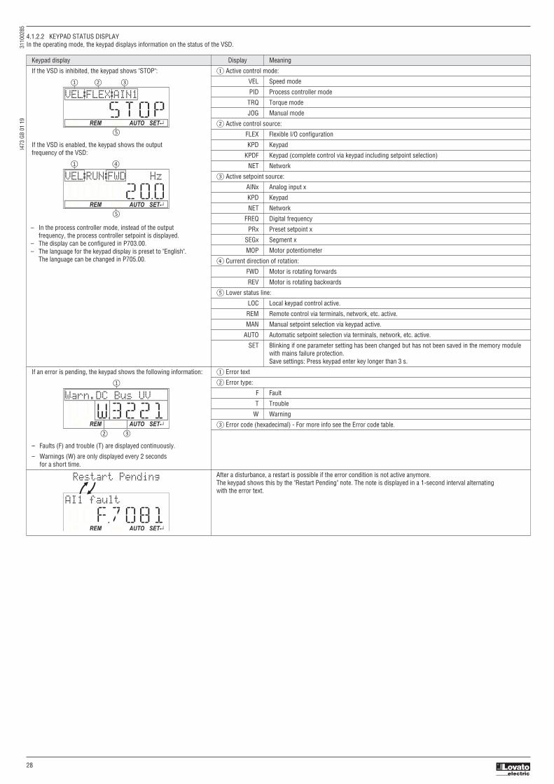
I473
GB
01 1
9
3
1100
285
28
4.1.2.2 KEYPAD STATUS DISPLAYIn the operating mode, the keypad displays information on the status of the VSD.
Keypad display Display Meaning
If the VSD is inhibited, the keypad shows "STOP": ① Active control mode:
VEL Speed mode
PID Process controller mode
TRQ Torque mode
JOG Manual mode
② Active control source:
FLEX Flexible I/O configuration
If the VSD is enabled, the keypad shows the output KPD Keypad
frequency of the VSD: KPDF Keypad (complete control via keypad including setpoint selection)
NET Network
③ Active setpoint source:
AINx Analog input x
KPD Keypad
NET Network
FREQ Digital frequency
PRx Preset setpoint x
SEGx Segment x
MOP Motor potentiometer
④ Current direction of rotation:
FWD Motor is rotating forwards
REV Motor is rotating backwards
⑤ Lower status line:
LOC Local keypad control active.
REM Remote control via terminals, network, etc. active.
MAN Manual setpoint selection via keypad active.
AUTO Automatic setpoint selection via terminals, network, etc. active.
SET Blinking if one parameter setting has been changed but has not been saved in the memory module with mains failure protection. Save settings: Press keypad enter key longer than 3 s.
If an error is pending, the keypad shows the following information: ① Error text
② Error type:
F Fault
T Trouble
W Warning
③ Error code (hexadecimal) - For more info see the Error code table.
– Faults (F) and trouble (T) are displayed continuously.
– Warnings (W) are only displayed every 2 seconds for a short time.
After a disturbance, a restart is possible if the error condition is not active anymore. The keypad shows this by the "Restart Pending" note. The note is displayed in a 1-second interval alternating with the error text.
STOP LOC REM MAN AUTO SET
VEL:FLEX:AIN1
OOOO2OOLOC REM MAN AUTO SET
HzVEL:RUN:FWD
O1W3221LOC REM MAN AUTO SET
VU suB CD.nraW
OOF7O81LOC REM MAN AUTO SET
AI1 fault
Restart Pending
– In the process controller mode, instead of the outputfrequency, the process controller setpoint is displayed.
– The display can be configured in P703.00.– The language for the keypad display is preset to "English". The language can be changed in P705.00.

I473
GB
01 1
9
3
1100
285
29
4.1.2.3 FUNCTION OF KEYPAD KEYS IN OPERATING MODEIn the operating mode, the keypad can be used for local control and for manual setpoint selection.
EXAMPLE: CHANGE SETPOINTIf the setpoints are selected manually via keypad, the frequency setpoint can be changed in the operating mode via the arrow keys (even while the motor is running):
Function of keypad keys in operating mode
Key Actuation Condition Action
Shortly Local keypad control active. Run motor. Display "LOC"
Remote control active Deactivate keypad triggered stop. Display "REM" The motor remains at standstill. Display "KSTOP" Display changes from "KSTOP" to "STOP".
Shortly No Jog operation Stop motor. Display "KSTOP"
Shortly Operating mode Change to parameterisation mode.
More than 3 s None (anytime possible) Save parameter settings in the user memory of the memory module.
Shortly During operation Scroll through information in the above status line.
Shortly Manual setpoint selection via keypad active. Change frequency setpoint. Display "MAN"
Shortly Operating mode Activate full keypad control (from version 4.1). Display "ON?" → Confirm with ↵ Control and setpoint selection can now only be carried out via keypad. Renewed clicking: Exit full keypad control. Display "OFF?" → Confirm with ↵ Shortly Local keypad control active. Reversal of rotation direction (from version 4.1). Display "LOC" Display "REV?" → Confirm with ↵
CTRL
R F
MAN SETLOC
VEL:KPD:KPD
000STOPMAN SETLOC
P202.01 Hz
000O2OOMAN SETLOC
P202.01 Hz
000O356
4.1.2.4 ERROR RESET WITH KEYPADUse the keypad key to reset a resettable error if the error condition no longer exists and no blocking time is active.
– The "Error code table" gives the blocking time (if available) for each error.
OOKSTOPREM AUTO SET
OOF7O81REM AUTO SET
AI1 fault
VEL:FLEX:AIN1
OOOO2OOREM AUTO SET
VEL:RUN:FWD Hz
1. Press keypad key. The error is reset. The motor remains stopped via keypad (display "KSTOP").2. In order to cancel the stop via keypad again: Press keypad key.

I473
GB
01 1
9
3
1100
285
30
4.1.2.5 KEYPAD PARAMETERISATION MODEIn the parameterisation mode of the keypad you can have actual values of the VSD displayed for purposes of diagnostics and change settings of the VSD.Use the ↵ to change from operating mode to the parameterisation mode.– If a write access protection is active for the VSD, the keypad automatically displays a log-in when changing to the parameterisation mode. You can either skip the log-in and thus keep the access
protection active or remove it temporarily by entering a valid PIN.– Use the to return to the operating mode.
PARAMETER GROUPSIn order to provide for quick access, all parameters of the VFD are divided into different groups according to their function.– Group 0 contains the configurable "Favorites". In the default setting these are the most common parameters for the solution of typical applications.– Based on the hundreds digit of the display code (Pxxx) you can quickly see in which group the parameter is to be found on the keypad:
FUNCTION OF THE KEYPAD KEYS IN THE PARAMETERISATION MODEIn the parameterisation mode, the arrow keys serve to select and change parameters.
Parameter Group/name Description
P1xx Group 1 - Diagnostics Diagnostic/display parameters for displaying device-internal process factors, current actual values, and status messages.
P2xx Group 2 - Basic setting Setting of the mains voltage, selection of the control and setpoint source, starting and stopping performance, frequency limits and ramp times.
P3xx Group 3 - Motor control Configuration of the motor and motor control
P4xx Group 4 - I/O setting Function assignment and configuration of the inputs and outputs
P5xx Group 5 - Network setting Configuration of the network (if available)
P6xx Group 6 - Process controller Configuration of the process controller
P7xx Group 7 - Additional functions Parameterisable additional functions
P8xx Group 8 - Sequencer The "sequencer" function serves to define a programmed sequence of speed setpoints, PID setpoints or torque setpoints for the motor control. Switching to the next setpoint can be executed in a time-based or event-based manner.
Function of the keypad keys in the parameterisation mode
Key Actuation Condition Action
Shortly Local keypad control active. Run motor. Display "LOC"
Remote control active Deactivate keypad triggered stop. Display "REM" The motor remains at standstill. Display "KSTOP" Display changes from "KSTOP" to "STOP".
Shortly No Jog operation Stop motor. Display "KSTOP"
Shortly Parameterisation mode Navigate to one level below. Group level → Parameter level → [SUB parameter level] → Editing mode
Editing mode Exit editing mode and accept new setting.
More than 3 s None (anytime possible) Save parameter settings in the user memory of the memory module.
Shortly Parameterisation mode Navigate to one level above. [SUB parameter level] → Parameter level → Group level → Operating mode
Editing mode Abort: Exit editing mode without accepting new setting.
Shortly Group level/Parameter level Navigate: Select group/parameter. Editing mode Change parameter setting.
Without function
Without function
CTRL
R F

I473
GB
01 1
9
3
1100
285
31
4.1.2.6 CHANGING VSD SETTINGS BY MEANS OF THE KEYPAD (general operation)
AUTO SETREM000O 15
AUTO SETREM
AUTO SETREMOP4OOxx
AUTO SETREM
AUTO SETREMOP42Oxx
AUTO SETREMOP42OO1
AUTO SETREMOP42OO2
1
AUTO SETREM
VEL:FLEX:AIN1
000STOP
GROUPOO GROUPO4
parameterisaonmode
Back
Back
Release brake
DO1 functionRelay function
Dig.out.function
gnittes O/I
tsil noitcnuF
Favorites
4.1.2.7 SAVE PARAMETER SETTINGS WITH KEYPADIf one parameter setting has been changed with the keypad but has not been saved in the memory module with mains failure protection, the SET display is blinking.In order to save parameter settings in the user memory of the memory module, press the keypad enter key longer than 3 s.
AUTO AUTO AUTOREM REM REM
VEL Saving Parameters deva S sretemaraP:FLEX:AIN1
SET SET SET000STOP SAVINGP SPSAVED
4.1.2.8 DISPLAY OF STATUS WORDS ON KEYPADSome diagnostics parameters contain bit-coded status words. Each single bit has a certain meaning.
Display of 16-bit status words on the keypad
AUTO SETREM
b.0000.0000.0000.0100
00xoOO4

I473
GB
01 1
9
3
1100
285
32
AUTO SETREM
b.0000.0000.0000.0001
HWXoOO1AUTO SETREM
b.0000.0000.0000.0000
LWXoOOO
4.1.2.9 KEYPAD SETTINGSFor the keypad various settings can be made, which are described in detail in the following subchapters.
Select language
Parameter Name / setting range / [default setting] Info
P705:00 Keypad language selection (KP language) Language selection for the keypad display.
0 No language selected
1 English
2 German
Change setpoint increment
Parameter Name / setting range / [default setting] Info
P701:00 Keypad setpoint increment (KP setp. incr.) Adaptation of the increment for keypad setpoints when a keypad arrow key is pressed once. 1 ... [1] ... 100 The value set serves as a multiplier for the preset increments. Setting 1 corresponds to the following increments: – 0.1 Hz for frequency setpoint P202:01. – 0.01 PUnit for process controller setpoint P202:02. – 0.1 % for torque setpoint P202:03. Notes: – With a setting > 1, the option of repeatedly changing the setpoint by pressing the key for a longer time is deactivated. – The setting only has an impact on the keypad setpoints. Example: with the setting "5", the keypad frequency setpoint is increased/decreased by 0.5 Hz every time the key is pressed.
Configure status displayDuring operation, the keypad displays the output frequency of the VLB3, or with an active PID control it shows the process controller setpoint. Alternatively, an optional diagnostic parameter can bedisplayed during operation.
Parameter Name / setting range / [default setting] Info
P703:00 Keypad status display (KP status displ.) 0 = normal display depending on the operating mode 0x00000000 ... [0x00000000] ... 0xFFFFFF00 – In case of an active frequency control, the keypad displays the output frequency of the drive. – In case of active PID control, the keypad displays the current Process controller setpoint in [P-Unit]. As an alternative, an optional diagnostic parameter can be set here, which is to be shown on the keypad during operation. – Format: 0xiiiiss00 (iiii = hexadecimal index, ss = hexadecimal subindex) – The lowest byte is always 0x00. – The keypad can be used to select the desired diagnostics parameter from a list.
P702:00 Speed display scaling (Scal.speed fact.) Factor for the scaling of the speed display in 0x400D (P101.00). 0.00 ... [0.00] ... 650.00 – With the setting "0.00", no scaling takes place. – Example: with the "16.50" and the actual frequency = 50 Hz, 0x400D (P101.00) shows the speed "825 units".
Configure R/F and CTRL keys Keypad rotation setup
Use the keypad to reverse the rotation direction at local keypad control.– After the key has been pressed, the reversal of rotation direction must be confirmed with the ↵ key. (The key serves to cancel the action.)
R F
R F
The keypad key – directly changes the keypad rotation setup in P708:02.– has no function in case of a bipolar setpoint selection (e. g. ±10 V). In this case, the direction of rotation is determined by the sign of the setpoint.– has no function if the rotation limitation "Only clockwise (CW) [0]" is set in P304:00.– has no function in the operating mode P301:00 = "MS: Torque mode [-1]".– has no function if the PID control is activated.– can be deactivated in P708:01.
R F
MANCOL TES
Keypad direction?
rEVMANCOL TES
Hz
2OOVEL:RUN:FWD
R FMANCOL TES
Hz
-2OOVEL:RUN:REV

I473
GB
01 1
9
3
1100
285
33
Keypad Full ControlThe "Keypad Full Control" control mode can be activated with the keypad key “CTRL”. Both the control and the setpoint selection are then made via the keypad. This special control mode can be, forinstance, used during the commissioning phase if external control and setpoint sources are not ready to use yet.
The keypad key CTRL– directly changes the setting in P708:03.– can be deactivated in P708:01.
Parameter
Parameter Name / setting range / [default setting] Info
P708:01 Keypad setup: CTRL & F/R key setup (Keypad setup: CTRL&F/R keys) Disable/enable CTRL and F/R key of the keypad. – From version 4.1
0 CTRL & F/R Disable
1 CTRL & F/R Enable
2 CTRL Enable F/R Disable
3 CTRL Disable F/R Enable
P708:02 Keypad setup: Select rotational direction (Keypad setup: Select rot.dir.) Instructed direction of rotation if local keypad control is active. – From version 4.1 – If the local keypad control is active, this setting can be directly changed via the keypad 0 Forward key if the key in P708:01 has not been disabled.
1 Reverse – When the remote control is changed over to local keypad control and
vice versa, this parameter is set to "Forward [0]".
P708:03 Keypad setup: Keypad Full Control (Keypad setup: Keypad Full Ctrl) Activate/deactivate full keypad control. – From version 4.1 – This setting can be changed directly via the keypad key CTRL if the key in P708:01 0 Off has not been disabled.
1 On – When the control mode is changed over, the motor is stopped and the "Forward"
2 Manual mode
direction of rotation is set.
R F
4.1.3 USB ADAPTERRequired materials– USB adapter (Type code: VLBX C02)– VLBXSW01 software– PC or laptop with free USB port– USB 2.0 cable (A plug on micro-B plug)
The VLBXSW01 software is available for free - see download area on the LOVATO Electric web (www.lovatoelectric.com)
Procedure1. Download and install the VLBXSW01 software.2. Connect USB adapter to VSD.3. Connect USB adapter to laptop with USB cable.
No external voltage or mains voltage is required to program the VSD.
4. Run VLBXSW01 software.5. Select “USB with module Lovato VLBXC02” for communication. Then click on “Insert” button.6. Program VSD:
Setting Guided setting windows
Diagnosis Actual status of VSD / IO / Errors / Controller
Parameter list Access to all parameters
Trend Record data trends from VSD values
For more information see documentation of the VLBXSW01 software.
7. Click on the following icon to save the parameters to the VSDs nonvolatile memory:
i
i
4.1.4 WI-FI ADAPTERRequired materials– Wi-Fi adapter (type code: VLBX C03).– VLBXSW01 software (version from 1.12)– PC or laptop with Wi-Fi connection.
Note. The Wi-Fi adapter is compatible with VLB3 with firmware revision >= 4.1.
The VLBXSW01 software is available for free - see download area on the LOVATO Electric web (www.lovatoelectric.com)
Procedure1. Download and install the VLBXSW01 software.2. Connect Wi-Fi adapter to VSD.3. Connect the PC to the WLAN generated by the Wi-Fi adapter.4. Run VLBXSW01 software.5. Select “Wi-Fi module VLBXC03” for communication. Then click on “Insert” button.6. Program VLB3 (are valid the same considerations given for USB adapter).
For details about Wi-Fi module VLBXC03 see chapter “5.9.4 WIRELESS LAN (WLAN)”.
i

I473
GB
01 1
9
3
1100
285
34
4.2 COMMISSIONING PROCEDUREUse the following table as a reminder that guides you through the commissioning procedure.
Step Action Information
1 Initial checks – Check delivery for completeness. – Check the nameplate information to ensure that you have the correct type of VSD for your motor/application. – Check for delivery damages. Don’t continue if your VSD seems to be damaged!
2 Module assembly See VLB3 installation manual, instruction I472 – Assembly your Safety Unit (Option)
3 Mechanical installation – Install the VSD according to the instruction.
4 Electrical installation – If you install the VSD to an IT network, remove the IT-screws. – Install the control wiring. – Install motor and supply wiring in accordance to the EMC requirements.
5 Functional test (if needed) Perform a uncoupled functional test for basic test
6 General parameter setup 4.4 General parameter setup (favorites) The VLB3 has linked the most common parameters to the favorites menu. With these parameters most common basic application can be solved.
7 Parameter setup (auxiliary functions) 5 Function & parameter description The VLB3 contains additional functions which can be used for more complex applications.
8 Testrun & tuning 5 Function & parameter description – Run the motor and check the performance of your application. – Adjust the corresponding parameter to tune your application.
9 Diagnose & troubleshooting 6 Troubleshooting Status LED and error messages are available for troubleshooting.
4.3 GENERAL PARAMETER SETUPThis chapter leads you through the favorites menu and gives you basic hints. For detailed information about the parameters and additional functions, see chapter “5 Function & parameter description”
4.3.1 DIAGNOSTIC
Parameter Type Description Default setting Unit
P100:0 Diagnostics Output frequency Actual value Hz
P104.0 Diagnostics Output motor current Actual value %
P106:0 Diagnostics Motor voltage Actual value VAC
P150:0 Diagnostics Error code Actual value –
Further diagnostic parameters are available in Group 1 – Diagnostics.
4.3.2 BASIC SETUP1. Select the default control location (terminal – flexible or keypad).2. Select the default frequency setpoint.3. Select the required start and stop method for your application.4. Check if correct mains voltage is set for your network.5. Set the motor frequency range (see illustration below).6. Set the motor acceleration/ deceleration time (see illustration below).
Parameter Type Description Default setting Unit
P200:0 Basic Setup Control source 0: Flexible –
P201:1 Basic Setup Frequency setpoint.source 2: Analog input 1 –
P203:1 Basic Setup Start method 0: Normal –
P203:3 Basic Setup Stop method 1: Standard Ramp –
P208:1 Basic Setup Mains voltage 230/400/480 Typecode dependent VAC
P210:0 Basic Setup Minimum frequency 0.0 Hz
P211:0 Basic Setup Maximum frequency 50.0 / 60.0 Typecode dependent Hz
P220:0 Basic Setup Acceleration time 1 5.0 sec
P221:0 Basic Setup Deceleration time 1 5.0 sec
Motor settings

I473
GB
01 1
9
3
1100
285
35
4.3.3 MOTOR CONTROL MODESMost applications like fans, pumps, and conveyors are possible in V/f (Voltage/frequency) mode. If the application requires more dynamic and speed assurance then the SLVC (Sensor less VectorControl) mode can be used.
1: P208:1 Mains voltage
2: P303:1 Base Voltage
5: P303:2 Base Frequency
6: P211:0 Maximum frequency
V/F mode
For V/f mode set the following parameters:
Example: 400V/50Hz MotorBase Voltage = 400VBase Frequency = 50 Hz
Parameter Type Description Default setting Unit
P300:0 Motor Control Motor control mode 6: VFC open loop –
P302:0 Motor Control V/f shape 0: Linear –
P303:1 Motor Control Base Voltage 230/400/480 Typecode dependent VAC
P303:2 Motor Control Base Frequency 50.0 / 60.0 Typecode dependent Hz
For SLVC mode refer to chapter “Motor control mode”.
MOTOR ROTATION RESTRICTIONSet this parameter if your application requires that the motor is running only in one direction:
Parameter Type Description Default setting Unit
P304:0 Motor Control Limitation of rotation 1: Both directions –
Tuning parameters
For most applications the default tuning parameters can be used:
Parameter Type Description Default setting Unit
P305:0 Motor control Switching frequency 21: 8kHz var/opt/4kHz min. kHz
P308:1 Motor control Max load for 60s 150 %
P316:1 Motor control Fixed V/f boost 0.4%...2.5% Typecode dependent %
P324:0 Motor control Max current 200.0 %
If the performance is insufficient during operation, see chapter “Motor Control setup” for tuning the parameters above.
Control selectionThe VLB3 can be controlled from various locations and in different ways.
Parameter Type Description Default setting Unit
P200:0 Basic Setup Control source 0: Flexible –
Basic functionalities:– VSD enable Enables the VSD. Signal must have the state TRUE (by Input or setting) to be able to start the motor.– Run/Stop Enables the running of the motor. Can be used as single signal or in combination with the signals Start Forward / Start Reverse. Signal must have the state TRUE (by Input or setting) to be able
to start the motor.– Start Forward / Start Reverse Used to start the motor (Positive edge triggered). Stop is down with the Run/Stop signal.– Run Forward / Run Reverse Used to run and stop the motor (Maintained signals)– Rotation invertion Inverts the speed setpoint– Fault Reset For a successful reset of a fault it is necessary to correct the condition that caused the fault first. Afterwards there are different possibilities to reset the fault:– Quick Stop (QSP) works as “pause” / “zero-speed” function. (The QSP ramp time can be set in P225:0)
In Flexible Control mode (P200:0) either VSD enable (P400:1) or Run/Stop (P400:2) must be assigned to I/O to ensure that the drive can always be stopped! (Exception: VSD is controlled from network, Network enable (P400:37) is HIGH)
i

I473
GB
01 1
9
3
1100
285
36
See chapter “5.2 Flexible I/O configuration” on page 32 for control application examples. See chapter “5.6.1 Function list (Run/Stop/Start/Jog/Reverse)” on page 76 for detailed information.
Parameter Type Description Default setting Unit
P400:1 I/O Setup VSD enable 1: TRUE –
P400:2 I/O Setup Run/Stop 11: Digital input 1 –
P400:3 I/O Setup Quick Stop [QSP] 0: Not connected –
P400:4 I/O Setup Reset fault 12: Digital input 2 –
P400:5 I/O Setup DC brake 0: Not connected –
P400:6 I/O Setup Start forward (CW) 0: Not connected –
P400:7 I/O Setup Start reverse (CCW) 0: Not connected –
P400:8 I/O Setup Run forward (CW) 0: Not connected –
P400:9 I/O Setup Run reverse (CCW) 0: Not connected –
P400:13 I/O Setup Invert rotation 13: Digital input 3 –
P400:18 I/O Setup Preset selection bit0 14: Digital input 4 –
P400:19 I/O Setup Preset selection bit1 15: Digital input 5 –
P400:20 I/O Setup Preset selection bit2 0: Not connected –
OUTPUT SELECTIONThe digital output and relay can be used as feedback signal for your control system.
Parameter Type Description Default setting Unit
P420:1 I/O Setup Relay function 51: Ready for operation –
P420:2 I/O Setup DO1 function 115: Release holding brake –
ANALOG INPUT 1 FOR SPEED SETPOINT
If you have defined the AI1 as your speed setpoint define the correct input scaling.
Parameter Type Description Default setting Unit
P430:1 I/O Setup AI1 input range 0: 0...10VDC –
P430:2 I/O Setup AI1 frequency @ min 0.0 Hz
P430:3 I/O Setup AI1 frequency @ max 50.0/60.0 *Typecode dependent Hz
ANALOG OUTPUT 1Analog output can be used as a feedback for your control system. Select the correct scaling and range (See Scaling):
Parameter Type Description Default setting Unit
P440:1 I/O Setup AO1 output range 1: 0...10VDC –
P440:2 I/O Setup AO1 function 1: Output frequency –
P440:3 I/O Setup AO1 min signal 0 –
P440:4 I/O Setup AO1 max signal 1000 –
FREQUENCY PRESETSDefine your basic preset frequency if required:
Parameter Type Description Default setting Unit
P450:1 I/O Setup Freq. preset 01 20.0 Hz
P450:2 I/O Setup Freq. preset 02 40.0 Hz
P450:3 I/O Setup Freq. preset 03 50.0/60.0 *Typecode dependent Hz
P450:4 I/O Setup Freq. preset 04 0.0 Hz
** Availability of scaling depending on type of control unit.
Speed setpoint

I473
GB
01 1
9
3
1100
285
37
5 FUNCTION & PARAMETER DESCRIPTION
5.1 PARAMETER / FUNCTION OVERVIEWThe VLB3 series is a multipurpose variable speed drive with a various amount of functionalities. For fast and easy commissioning the parameters are grouped. The group 0 “Favorites” contains alink to the most common used parameters. The following graphic shows an overview over the functionalities and where they can be programmed. For detailed information see the correspondingchapter.
Every parameter has a hexadecimal index number. Parameters which are visible on the keypad have also a parameter number. In the VLBXSW01 software the parameter number and thehexadecimal index are visible. Every parameter can have subindex.
Example Parameter number Index
Base Frequency P303.02 0x2B01:002
Control source P200.00 0x2824:000
P510:1 0x2321:1 Node ID (*)
1... [1]...247 Modbus node address
Parameter witch are not visible on the keypad are marked in the manual as P (without number).
Parameters or selections with marking (*) are not available on all control unit types.
i
Parameter number Index Subindex

I473
GB
01 1
9
3
1100
285
38
5.2 START, STOP AND ROTATING DIRECTION COMMANDS
5.2.1 CONTROL SELECTIONThe selected "control source" serves to provide the VLB3 with its start, stop, and reversal commands.Possible control sources:– Digital inputs– Keypad– NetworkThe following signal flow shows the internal control logics:
In order to control the VLB3 from the network, the network share P400:37 must be configured. It is important to note that the following functions are still active in network control mode:– VSD enable P400:1– Start/stop P400:2– Activate quick stop P400:3– Reset error P400:4– DC-injection brake P400:5– Jog forward (CW) P400:10– Jog reverse (CCW) P400:11All other function triggers are inactive while the VLB3 is in network control mode (0x2361:006 to 0x2361:025).
NOTICE!Stop commands are always active from any connected source, regardless of which control source is selected!If, for example, the network control is activated and a keypad is plugged in for diagnostic purposes, the motor is also stopped when the keypad key is pressed.Exception: a stop command has no effect in jog operation.
Details– The default setting "Flexible I/O configuration [0]" in P200:0 enables a flexible control of the VLB3 via digital inputs, network and keypad. The control of the VLB3 via the digital inputs is
preconfigured. For details see the subchapter "Flexible I/O configuration".– If the keypad is to be used as the control source for the application, set "Keypad [1]" in P200:0. For details, see subchapter "Keypad control". – The control source that is currently active is displayed in P125:1.
i
P200:00 0x2824 Control selection
0: Flexible I/O configuration 0: Flexible I/O configuration 1: Keypad This selection enables a flexible assignment of the start, stop, and rotating direction commands with digital signal sources. – Digital signal sources can be digital inputs, network and keypad. – The I/O configuration is made via the parameters P400:xx.
1: Keypad This selection enables the motor to be started exclusively via the start key of the keypad. Other signal sources for starting the motor are ignored. Note! – The functions "Enable VSD" P400:1 and "Run" P400:2 must be set to TRUE to start the motor. – If jog operation is active, the motor cannot be stopped via the keypad key.

I473
GB
01 1
9
3
1100
285
39
5.2.2 FLEXIBLE I/O CONFIGURATIONUse parameter (P400:xx) to individually adapt the VSD control to the respective application. This is basically effected by assigning digital signal sources ("triggers") to functions of the VSD.
A digital signal source can be assigned to several functions.Possible consequence: unforeseeable behaviour of the drive in case of incorrect assignment
Carry out assignment of a digital signal source to several functions with greater care.
Details– Each subcode of P400 is permanently assigned to a specific function. Functions are for example "Enable VSD", "Activate quick stop" or "Start forward (CW)".– For a function, exactly one (digital) trigger can be set:
i
– Possible triggers to be selected are for example the digital input and internal status signals of the VSD.– A list of all triggers available can be found in the description for the parameter P400:1.– If the trigger condition is met, the corresponding function is executed. More details with regard to the respective trigger conditions can be gathered from the functional descriptions in the
following subchapters.
Example: changing the function assignment of a digital inputTask for this example:1. The preset assignment of the digital input 3 for "Invert rotation" function is to be cancelled.2. Instead, the digital input 3 is to be assigned to the "Activate DC braking" function.For this purpose, the following two settings are required:
Default:
Trigger Function
Digital input 1 Run
Function Trigger Function
P400:13 Digital input 3 Invert rotation
New:
Function Trigger Function
P400:13 Not connected [0] Invert rotation
P400:5 Digital input 3 [13] Activate DC braking
5.2.3 KEYPAD CONTROLThe "Keypad" control selection enables the motor to be started exclusively via the start key of the keypad. Other signal sources for starting the motor are ignored.
DetailsIf the keypad is to be used as the sole control source for the application, selection "Keypad [1]" is to be set in P200:0.If the local keypad control is active, "LOC" is displayed in the lower status row of the keypad.The keys on the keypad then have the following function:
The following functions continue to be active:– P400:1: Enable VSD– P400:3: Activate quick stop– P400:5: Activate DC braking– P400:10: Jog foward (CW)– P400:11: Jog reverse (CCW)– P400:13: Reverse rotational direction– P400:43: Activate fault 1– P400:44: Activate fault 2
Function of the keypad keys in the parameterisation mode
Key Actuation Condition Action
Shortly Local keypad control active. Run motor. Display "LOC"
Shortly No Jog operation Stop motor. Display "KSTOP"
Shortly Operating mode Change to parameterisation mode.
Longer than 3 s None (anytime possible) Save parameter settings in the user memory of the memory module.
Shortly During operation Scroll through informaion in the above status line.
Shortly Operating mode Activate full keypad control Display “ON?” → confirm with ↵ Control and setpoint slection can now only be carried out via keypad. Renewed clocking: Exit full keypad control. Display “OFF?” → confirm with ↵ Shortly Local keypad control active. Reversal of rotation direction. Diplay “LOC” Display “REV?” → confirm with ↵
CTRL
R F

I473
GB
01 1
9
3
1100
285
40
5.2.4 KEYPAD FULL CONTROLThe "Keypad Full Control" control mode can be activated with the keypad key “CTRL”. Both the control and the setpoint selection are then made via the keypad. This special control mode can be,for instance, used during the commissioning phase if external control and setpoint sources are not ready to use yet.
CAUTION!If the "Keypad Full Control" control mode is active, the "Run" P400:2 function is internally set to TRUE.In this case, the motor cannot be stopped via this function. For stopping the motor, use the keypad key, deactivate the VSD enable or activate the "quick stop" function.
Details– After the “CTRL” key has been pressed, the activation of the control mode must be confirmed with the key. (The key serves to cancel the action.)– When the control mode is changed over, the motor is first stopped and the "Forward" direction of rotation is set. Then, the motor can be started and stopped via the keypad.
If the "Keypad Full Control" control mode is active,– the keypad shows the warning "Keypad full ctrl" alternately with the status display.– the set standard setpoint sources are ignored.– a change-over to other setpoint sources is not possible.– a change-over to network control is not possible.– the following functions continue to be active:– P400:1: Enable VSD– P400:3: Activate quick stop– P400:5: Activate DC braking– P400:10: Jog foward (CW)– P400:11: Jog reverse (CCW)– P400:13: Reverse rotational direction– P400:43: Activate fault 1– P400:44: Activate fault 2The control mode can be terminated again if the "CTRL" keypad key is pressed again.

I473
GB
01 1
9
3
1100
285
41
5.2.5 FLEXIBLE I/O CONFIGURATION OF THE START, STOP AND ROTATING DIRECTION COMMANDSConfiguration of the triggers for the basic functions for controlling the motor.
DetailsThe following table contains a short overview of the basic functions. For more details see the parameter descriptions.
Function Info
Enable VSD (P400:1) Enable/disable operation. – The function must be set to TRUE to start the motor. Either via digital input or by default setting "Constant TRUE [1]". – If the function is set to FALSE, the VSD is disabled. The motor becomes torqueless (coasts). See Example 6: Enable VSD.
Run (P400:2) Function 1: Start / stop motor (default setting) – Function 1 is active if no further start commands (start forward/start reverse) have been connected to triggers, no keypad control is active and no network control is active. TRUE: Let motor rotate forward (CW). FALSE: Stop motor. See Example 1: Start/stop (1 signal) and reversal.
Function 2: Start enable/stop motor – Function 2 is active if further start commands have been connected to triggers, keypad control is active or network control is active. TRUE: Start commands of the active control source are enabled. FALSE: Stop motor. See Example 2: Start forward/start reverse/stop (edge-controlled). See Example 3: Run forward/Run reverse/stop (status-controlled).
Activate quick stop (P400:3) Bring motor to a standstill in best time. See Example 4: Quick stop.
Start forward (P400:6) Start motor edge-controlled. – In order to be able to start the motor, the "Run" function must be set to TRUE. Start reverse (P400:7) – The motor is stopped by resetting the "Run" function to FALSE. – Functions are deactivated in case of keypad or network control. See Example 2: Start forward/start reverse/stop (edge-controlled).
Run forward (P400:8) Let the motor rotate in a status-controlled way. – In order to be able to start the motor, the "Run" function must be set to TRUE. Run reverse (P400:9) – Functions are deactivated in case of keypad or network control. See Example 3: Run forward/Run reverse/stop (status-controlled).
Jog foward (P400:10) Jog operation: Let the motor rotate in a status-controlled way with setpoint preset. CAUTION! The jog operation has a higher priority than the "Run" function, all other start commands and the keypad key . Jog reverse (P400:11) – If jog operation is active, the motor cannot be stopped with the previously mentioned functions! – However, jog operation can be interrupted by the "Quick stop" function. – Jog operation can always be activated, even in case of keypad or network control. See Example 5: Jog forward/Jog reverse.
Invert rotation (P400:13) Invert frequency setpoint. – Function can be used in combination with all start commands. – Function is deactivated in case of network control. See Example 1: Start/stop (1 signal) and reversal.
ASSIGNMENT GUIDELINESThe error message "Trigger/functions connected incorrectly" (error code 25216 | 0x6280) is output if one of the following assignment guidelines is not observed:– If the "flexible I/O configuration" is active as control source, the "Enable VSD" function or the "Run" function must be connected to a digital input in order that the motor can be stopped again any
time!– In case of keypad or network control, the two functions "Enable VSD" and "Run" can also be set to "Constant TRUE [1]" to start the motor.– The use of the "Start forward (CW)" and "Start reverse (CCW)" functions excludes the use of the "Run forward (CW)" and "Run reverse (CCW)" and vice versa.
Example 1: Start/stop (1 signal) and reversalThis example shows a simple control option via two switches which should be sufficient for many applications:– Switch S1 starts the motor in forward direction of rotation. Switch S1 in the initial position stops the motor again.– Switch S2 switches the direction of rotation.
R1 = Frequency setpoint selectionS1 = RunS2 = Invert rotation
The example uses the preset I/O configuration of the VSD:
Parameter Name Setting
P400:1 Enable VSD Constant TRUE [1]
P400:2 Run Digital input 1 [11]
P400:13 Invert rotation Digital input 3 [13]

I473
GB
01 1
9
3
1100
285
42
① If the VSD is enabled and no error is active, the motor can be started with the "Run" function in forward rotating direction.② If "Run" is set to FALSE, the motor is stopped with the stop method set in P203:3. In the example: Stop with standard ramp.
Example 2: Start forward/start reverse/stop (edge-controlled)
The "Run" function automatically becomes a "start enable" if the functions "Start forward (CW)"/ "Start reverse (CCW)" are connected to triggers.
This example shows an edge-controlled start/stop via three buttons:– In the non-operating state of button S1 (normally-closed contact), there is already a start enable.– Button S2 starts the motor in forward rotating direction.– Button S3 starts the motor in backward rotating direction.– Button S1 (normally-closed contact) stops the motor by (short-time) cancellation of the start command. The VSD then waits for the next start command via button S2/S3.
i
R1 = Frequency setpoint selectionS1 = StoppingS2 = Start forwardS3 = Start reverse
Parameter Name Setting
P400:1 Enable VSD Constant TRUE [1]
P400:2 Run Digital input 1 [11]
P400:4 Reset fault Not connected [0]
P400:6 Start forward Digital input 2 [12]
P400:7 Start reverse Digital input 3 [13]
P400:13 Invert rotation Not connected [0]

I473
GB
01 1
9
3
1100
285
43
① The "Run" functions serves as start enable for the functions "Start forward " and "Start reverse ". Without start enable, the motor cannot be started.② If the start command is cancelled, the motor is stopped with the stop method set in P203:3. In the example: Stop with standard ramp.③ If, at start enable, "Start forward " and "Start reverse " are already set to TRUE, the motor remains stopped and the VSD waits for the next valid start edge.
Example 3: Run forward/Run reverse/stop (status-controlled)
The "Run" function automatically becomes a "start enable" if the functions "Run forward (CW)"/"Run reverse (CCW)" are connected to triggers.
This example shows a status-controlled start/stop via three switches:– Switch S1 enables the start. Without start enable, the motor cannot be started.– Switch S2 starts the motor in forward direction of rotation.– Switch S3 starts the motor in backward direction of rotation.– The motor is stopped by cancelling the run commands (switches S2 and S3 open) or by cancelling the start enable (switch S1 open).
i
R1 = Frequency setpoint selectionS1 = Start enableS2 = Run forwardS3 = Run reverse
Parameter Name Setting
P400:1 Enable VSD Constant TRUE [1]
P400:2 Run Digital input 1 [11]
P400:4 Reset fault Not connected [0]
P400:8 Run forward Digital input 2 [12]
P400:9 Run reverse Digital input 3 [13]
P400:13 Invert rotation Not connected [0]

I473
GB
01 1
9
3
1100
285
44
① The "Run" functions serves as start enable for the functions "Run forward" and "Run reverse". Without start enable, the motor cannot be started.② If the start command is cancelled, the motor is stopped with the stop method set in P203:3. In the example: Stop with standard ramp. After a renewed start enable, the VSD waits for the next
run command.③ If, at start enable, either "Run forward " or "Run reverse" is set to TRUE, the motor starts into the triggered direction.④ The VSD always responds to the run command detected last (if start enable is available). In the example, the "Run reverse " command replaces the still active "Run forward " command.⑤ If, at start enable, both run commands are set to TRUE, the motor remains stopped until only one valid run command is available.
Example 4: Quick stop
This example illustrates the "quick stop" function. If quick stop is activated, the motor is brought to a standstill within the deceleration time set in P225:0.– Switch S1 starts the motor in forward direction of rotation. Switch S1 in the initial position stops the motor again.– Switch S2 activates the "quick stop" function.
Cancelling the quick stop causes a restart of the motor if “Run” is still active (switch S1 closed!)i
R1 = Frequency setpoint selectionS1 = RunS2 = Activate quick stop
Parameter Name Setting
P400:1 Enable VSD Constant TRUE [1]
P400:2 Run Digital input 1 [11]
P400:3 Activate quick stop Digital input 2 [12]
P400:4 Reset fault Not connected [0]
P220:0 Acceleration time 1 3.0 s
P221:0 Deceleration time 1 3.0 s
P225:0 Quick stop deceleration time 1.0 s

I473
GB
01 1
9
3
1100
285
45
① If quick stop is activated, the motor is decelerated to the frequency setpoint 0 Hz within a short period of time. The "Quick stop active [54]" status is set as long as quick stop is activated. The "Stop active [53]" status is not set.
② An active stop command is interrupted by a quick stop.③ If quick stop is cancelled again before standstill is reached, stopping is continued with the stop method set in P203:3. In the example: Stop with standard ramp.
Example 5: Jog forward/Jog reverseThis example illustrates the functions "Jog forward " and "Jog reverse " for Jog operation.– Switch S1 starts the motor in forward direction of rotation. Switch S1 in the initial position stops the motor again.– Button S2 starts the motor in forward direction of rotation with frequency preset 5.– Button S3 starts the motor in backward direction of rotation with frequency preset 6.– The motor rotates in jog operation as long as the respective button is pressed. If both buttons are pressed at the same time, the motor is stopped.
The jog operation has a higher priority than the "Run" function, all other start commands and the keypad key .
If jog operation is active, the motor cannot be stopped with the previously mentioned functions!– The jog operation is stopped by cancelling the functions "Jog foward "/"Jog reverse".– The jog operation can be interrupted with the "Activate quick stop" (P400:3) function.
i
R1 = Frequency setpoint selectionS1 = RunS2 = Jog forwardS3 = Jog reverse
Parameter Name Setting
P400:1 Enable VSD Constant TRUE [1]
P400:2 Run Digital input 1 [11]
P400:4 Reset fault Not connected [0]
P400:10 Jog forward Digital input 2 [12]
P400:11 Jog reverse Digital input 3 [13]
P400:13 Invert rotation Not connected [0]
P450:5 Frequency setpoint presets: Preset 5 15 Hz (is used for jog forward)
P450:6 Frequency setpoint presets: Preset 6 10 Hz (is used for jog reverse)

I473
GB
01 1
9
3
1100
285
46
① If "Jog foward" and "Jog reverse" are activated at the same time, the motor is stopped with the stop method set in P203:3 and the jog operation must be triggered again.② The jog operation cannot be terminated with the "Run" function but only by cancelling the jog command.
Example 6: Enable VSDThis example shows how to use the "Enable VSD" function for a separate enable input.– In idle state of switch S1 (normally-closed contact), "Enable VSD" is already available.– Switch S2 starts the motor in forward rotating direction (if switch S1 is closed). Switch S2 in initial position stops the motor again.– Switch S1 disables the VSD. The motor becomes torqueless (coasts).
R1 = Frequency setpoint selectionS1 = Disable VSDS2 = Run
Parameter Name Setting
P400:1 Enable VSD Digital input 1 [11]
P400:2 Run Digital input 2 [12]
P400:4 Reset fault Not connected [0]

I473
GB
01 1
9
3
1100
285
47
① If the VSD is enabled and no error is active, the motor can be started with the "Run" function in forward rotating direction.② If "Enable VSD" is set to FALSE, the VSD is disabled. The motor becomes torqueless and coasts to standstill as a function of the mass inertia of the machine.③ Without "Enable VSD", the motor cannot be started.④ In the default setting, the motor does not start if the "Run" function is set to TRUE during "Enable VSD" . After "Enable VSD", must be retriggered to start the motor.
5.2.6 CONTROL/RESTRICT DIRECTION OF ROTATION OF THE MOTORIn the default setting, both directions of motor rotation are enabled. Optionally, the direction of rotation can be restricted so that only a clockwise rotation (CW) of the motor is possible.
PreconditionsWiring of the motor phases must be carried out correctly with regard to the direction of motor rotation.In the documentation and the parameter selection texts, the following terms are used for the direction of rotation:– Forward = clockwise direction of rotation (CW)– Reverse = counter-clockwise direction of rotation (CCW)
DetailsThe direction of rotation of the motor can be controlled in various ways:– Via the function "Reverse rotational direction". Possible triggers for the function "Reverse rotational direction" are available for selection in P400:13, e.g. the digital inputs and internal status
signals of the drive.– Via the network. The definition of the direction of rotation is possible via the mappable NetWordIN1 data word or one of the predefined process data words.– By specifying a bipolar setpoint value via an analogue input. Either via a bipolar input range (-10 ... +10 V) or the configuration of a bipolar setting range.If a reversal of rotation is not required, the direction of rotation can be restricted in P304:0 to "Only clockwise (CW)[0]".
P304:0 0x283A Limitation of rotation
0: Only clockwise (CW) 0: Only clockwise (CW) 1: Both rotational directions The motor can only be rotated clockwise (CW). The transfer of negative frequency and PID setpoints to the motor control is prevented. – This function takes effect after the "Reverse rotational direction" function P400:13. – Since this function only prevents negative setpoints, counter-clockwise rotation (CCW) is possible if the motor has been wired for this rotating direction.
1: Both rotational directions Both directions of motor rotation are enabled.
Activate keypad control Activate network control Active control source P400:12 P400:37
FALSE / Not connected FALSE / Not connected Flexible I/O configuration (default setting) – The motor is controlled via the digital inputs.
FALSE / Not connected TRUE Network – Starting the motor is only possible via the network control word. – Exception: jog operation;.
TRUE Any Keypad – Starting the motor is only possible via the keypad key. – Exception: jog operation.
5.2.7 CHANGING THE CONTROL SOURCE DURING OPERATIONThe term "control sources" in this connection refers to the digital signal sources from which the VLB3 receives its start, stop, and reversal commands.Possible control sources:– Digital inputs– Keypad– Network
DetailsFirst, select P200:0 whether the start of the motor is to be configured flexibly (default setting) or exclusively via the keypad. If "Flexible I/O configuration" is set, a change-over from one control source to another can be effected during operation via the functions listed in the following table. The VLB3 not only supportssuch a change-over via its digital inputs, but also as a function of internal drive states.

I473
GB
01 1
9
3
1100
285
48
5.2.7.1 EXAMPLE: CHANGE-OVER FROM TERMINAL CONTROL TO KEYPAD CONTROL– The control is executed primarily via the I/O terminals: Switch S1 serves to start and stop the motor.– Switch S2 serves to optionally change over to local keypad control. In case of activated keypad control, the motor can only be started via the keypad key. However, the condition is that switch
S1 is closed.– If switch S1 is opened again or the keypad key is pressed, the motor is stopped (irrespective of the active control source).
R1 = Frequency setpoint selectionS1 = RunS2 = Activate keypad control
Parameter Name Setting
P400:1 Enable VSD Constant TRUE [1]
P400:2 Run Digital input 1 [11]
P400:4 Reset fault Not connected [0]
P400:12 Activate keypad control Digital input 2 [12]
P200:0 Control selection Flexible I/O configuration [0]
The status signals can be assigned to digital outputs.① When changing over to another control source, the motor is first stopped with the stop method set in P203:3.② The motor will also be stopped if the "Run" function is deactivated or the keypad key is pressed (irrespective of the active control source).③ After stopping with the keypad key and before a renewed start command from another control source, the key on the keypad must be pressed to cancel the keypad stop again
("KSTOP").

I473
GB
01 1
9
3
1100
285
49
5.2.7.2 EXAMPLE: CHANGE-OVER FROM TERMINAL CONTROL TO NETWORK CONTROL– The control is executed primarily via the I/O terminals. The switch S1 serves to start and stop the motor.– The switch S2 serves to activate the network control. In the case of activated keypad control, the motor can only be started via the network control word. However, the condition is that the
switch S1 is closed.– If the switch S1 is opened again, the motor is stopped (irrespective of the active control source).
R1 = Frequency setpoint selectionS1 = RunS2 = Activate network control
Parameter Name Setting
P400:1 Enable VSD Constant TRUE [1]
P400:2 Run Digital input 1 [11]
P400:4 Reset fault Not connected [0]
P400:37 Activate network control Digital input 2 [12]
P200:0 Control selection Flexible I/O configuration [0]
The status signals can be assigned to digital outputs.① When changing over to another control source, the motor is first stopped with the stop method set in P203:3.② The motor will also be stopped if the "Run" function is deactivated (irrespective of the active control source).③ Commands via the network are ignored if the network control is not active.

I473
GB
01 1
9
3
1100
285
50
5.3 GROUP 1 – DIAGNOSTICS
General:Bit coded status words are displayed on the keypad as described in the following picture:
Display of bit coded status word on keypad
5.3.1 GENERAL DIAGNOSTIC DATA
P100:0 0x2DDD:0 Output frequency
-- ... [Actual value] ... -- Hz Actual motor frequency
P101:0 0x400D:0 Scaled actual value
-- ... [Actual value] ... -- Units Actual motor speed in user units. Actual frequency x Scaling factor (P702:0)
P102:0 0x2B0E:0 Frequency setpoint
-- ... [Actual value] ... -- Hz Actual frequency setpoint
P103:0 0x6078:0 Actual motor current
-- ... [Actual value] ... -- % Actual motor current in % of P323:0
P104:0 0x2D88:0 Actual motor current
-- ... [Actual value] ... -- A Actual motor current
P105:0 0x2D87:0 DC-bus voltage
-- ... [Actual value] ... -- V Actual DC-Link voltage
P106:0 0x2D89:0 Actual motor voltage
-- ... [Actual value] ... -- VAC Actual motor voltage
P107:0 0x6077:0 Actual torque
-- ... [Actual value] ... -- % Actual motor torque (100% = Max. torque)
5.3.2 OUTPUT POWER
P108:1 0x2DA2:1 Effective power
-- ... [Actual value] ... -- kW Actual motor effective power
P108:2 0x2DA2:2 Apparent power
-- ... [Actual value] ... -- kVA Actual motor apparent power
5.3.3 OUTPUT ENERGY
P109:1 0x2DA3:1 Motor
-- ... [Actual value] ... -- kWh Estimated energy at the VSD output when the motor is being driven
P109:2 0x2DA3:2 Generator
-- ... [Actual value] ... -- kWh Estimated energy at the VSD output when the motor is regenerating

I473
GB
01 1
9
3
1100
285
51
5.3.4 ANALOG INPUT 1 DIAGNOSIS
P110:1 0x2DA4:1 Percent value
-- ... [Actual value] ... -- % Actual value of AI1 in % of the selected input range
P110:2 0x2DA4:2 Frequency value
-- ... [Actual value] ... -- Hz Actual value of AI1 as frequency setpoint
P110:3 0x2DA4:3 PID value
-- ... [Actual value] ... -- P Unit Actual value of AI1 as PID input
P110:4 0x2DA4:4 Torque value
-- ... [Actual value] ... -- % Actual value of AI1 as torque setpoint
P110:16 0x2DA4:16 Status analog input 1
-- ... [Actual value] ... -- Bit coded status of AI1
5.3.5 ANALOG INPUT 2 DIAGNOSIS
P111:1 0x2DA5:1 Percent value
-- ... [Actual value] ... -- % Actual value of AI2 in % of the selected input range
P111:2 0x2DA5:2 Frequency value
-- ... [Actual value] ... -- Hz Actual value of AI2 as frequency setpoint
P111:3 0x2DA5:3 PID value
-- ... [Actual value] ... -- P Unit Actual value of AI2 as PID input
P111:4 0x2DA5:4 Torque value
-- ... [Actual value] ... -- % Actual value of AI2 as torque setpoint
P111:16 0x2DA5:16 Status analog input 2
-- ... [Actual value] ... -- Bit coded status of AI2
5.3.6 ANALOG OUTPUT 1 VALUE
P112:1 0x2DAA:1 Voltage
-- ... [Actual value] ... -- V Actual output voltage of A01
P112:2 0x2DAA:2 Current
-- ... [Actual value] ... -- mA Actual output current of A01
5.3.7 HTL INPUT DIAGNOSTIC
P115:1 0x2642:1 Input frequency
Actual input value at the HTL input
P115:2 0x2642:2 Frequency setpoint
Actual input value at the HTL input scaled at frequency value
P115:3 0x2642:3 PID setpoint
Actual input value at the HTL input scaled at process controller value
P115:4 0x2642:4 Torque setpoint
Actual input value at the HTL input scaled as torque value percent (1001. = P325:0)
5.3.8 HEATSINK TEMPERATURE MONITORING
P117:1 0x2D84:1 Heatsink temperature
-- ... [Actual value] ... -- °C Actual heatsink temperature
– 0x2D84:002 Heatsink temperature warning threshold
50.0 ... [80.0]* ... 100.0 °C Warning threshold for temperature monitoring. * Default setting depending on the size. – If the heatsink temperature exceeds the threshold set here, the VSD outputs a warning. – The warning is reset with a hysteresis of approx. 5 °C. – If the heatsink temperature increases further and exceeds the nonadjustable error threshold (100 °C), the VSD changes to the "Fault" device status. The VSD is disabled and thus any further operation is stopped.

I473
GB
01 1
9
3
1100
285
52
5.3.9 I/O STATUS
P118:0 0x60FD:0 Digital inputs status
Bit # description: Status of digital input (Bit coded) 16: Level at digital input 1 17: Level at digital input 2 18: Level at digital input 3 19: Level at digital input 4 20: Level at digital input 5 21: Level at digital input 6 22: Level at digital input 7 25: Low active - NPN
P119:0 0x2DAC:0 Keypad status
Bit # description: Keypad status (Bit coded) 0: Start Key 1: Stop Key 2: Up Key 3: Down Key 4: Enter Key 5: Escape Key
P120:0 0x2DAD:0 Internal hardware states
Bit # description: Status of digital outputs and relay (Bit coded) 0: Relay 1: Digital output 1 10: Charge Relay
5.3.10 PROCESS CONTROLLER DIAGNOSIS
P121:1 0x401F:1 PID setpoint
-- ... [Actual value] ... -- PUnit Actual PID setpoint
P121:2 0x401F:2 PID feedback
-- ... [Actual value] ... -- PUnit Actual PID feedback
P121:3 0x401F:3 PID status
Bit # description: PID status (Bit coded) 0: Process controller off 1: PID output set to 0 2: PID I-component set to 0 3: PID influence shown 4: Setpoint = actual value 5: Sleep mode active
5.3.11 MOTOR PROTECTION I2XT
P123:0 0x2D4F:0 Motor utilisation (i²*t)
-- ... [Actual value] ... -- % Actual thermal load of the motor (I2xt)

I473
GB
01 1
9
3
1100
285
53
5.3.12 CONTROL / SETPOINT SOURCE
P125:1 0x282B:1 Active control source
--… [Actual value] …-- Display of the control source that is currently active. 0:Flexible I/O configuration 1:Network 2:Keypad 8:Keypad full control
P125:2 0x282B:2 Active setpoint source
--… [Actual value] …-- Display of the control source that is currently active. 0:Not selected 1: Analog input 1 2: Analog input 2 3: Keypad setpoint 4: HTL input 5: Network Setpoint 11: Setpoint preset 1 12: Setpoint preset 2 13: Setpoint preset 3 14: Setpoint preset 4 15: Setpoint preset 5 16: Setpoint preset 6 17: Setpoint preset 7 18: Setpoint preset 8 19: Setpoint preset 9 20: Setpoint preset 10 21: Setpoint preset 11 22: Setpoint preset 12 23: Setpoint preset 13 24: Setpoint preset 14 25: Setpoint preset 15 31: Segment preset 1 32: Segment preset 2 33: Segment preset 3 34: Segment preset 4 35: Segment preset 5 36: Segment preset 6 37: Segment preset 7 38: Segment preset 8 39: Last segment 50: Motor potentiometer 51: PID setpoint
P125:3 0x282B:3 Keypad LCD status
Bit # description: Bit-coded state of the keypad status displays. 0: LOC LOC=1 means local keypad control active. 1: REM REM=1 means remote control via terminals, network, etc. active. 2: MAN MAN=1 means manual setpoint selection via keypad active. 3: Auto Auto=1 means automatic setpoint selection via terminals, network, etc. active. 4: Set Set=1 means a parameter setting has been changed but not been saved yet in the memory module with mains failure protection.
P125:4 0x282B:4 Active drive mode
--… [Actual value] …-- Display of the active drive mode. 0: "Velocity mode" active. 1: PID control active. 2: “Torque mode” active. 4: "Jog foward (CW)" or "Jog reverse (CCW)" function active.
P125:5 0x282B:5 Most recently used control register
--… [Actual value] …-- Display of the network register for the control that was accessed last (e. g. 0x6040 or 0x400B:1). – Format: 0xiiiiss00 (iiii = hexadecimal index, ss = hexadecimal subindex) – The lowest byte is always 0x00.
P125:6 0x282B:6 Most recently used setpoint register
--… [Actual value] …-- Display of the network register for setpoint selection that was accessed last (e. g. 0x6042 or 0x400B:3). – Format: 0xiiiiss00 (iiii = hexadecimal index, ss = hexadecimal subindex) – The lowest byte is always 0x00.

I473
GB
01 1
9
3
1100
285
54
5.3.13 VSD STATUS
P126:1 0x282A:1 Cause of disable
Bit # description: Cause of controller stop (Bit coded) 0: Flexible I/O: Inhibit 1: Network inhibit 2: Axis inhibit 6: DC bus fault 7: Drive not ready 8: Quick stop actiive 9: Motor parameter identification 10: Auto brake 12: CiA 402 disabled 13: CIA402 Quick stop inhibit 14: STO inhibit 15: CiA402 mode disabled
P126:2 0x282A:2 Cause of quick stop
Bit # description: Cause of quick stop (Bit coded) 0: Flexible I/O: configuration 1: Network 2: Axis command 6: Error response
P126:3 0x282A:3 Cause of stop
Bit # description: Cause of stop (Bit coded) 0: Flexible I/O: Start disabled 1: Flexible I/O: Run forward 2: Flexible I/O: Run reverse 3: Flexible I/O: Jog forward 4: Flexible I/O: Jog reverse 5: Network 6: Keypad 7: Control mode transition 8: End of sequence 15: Waiting for start
P126:5 0x282A:5 Device status
0: Initialisation Actual state of VSD 2: Not Ready to Switch On 3: Switch On Disabled 4: Ready to Switch On 5: Switched on 6: Operation enabled 7: Disable Operation 8: Shut Down 9: Quick stop active 10: Fault reaction active 11: Fault
5.3.14 DEVICE OVERLOAD MONITORING (i*t)The VSD calculates the i*t utilisation in order to protect itself against thermal overload. In simple terms: a higher current or an overcurrent that continues for a longer time causes a higher i*tutilisation.
DANGER!Uncontrolled motor movements by pulse inhibit.When the device overload monitoring function is activated, pulse inhibit is set and the motor becomes torqueless. A load that is connected to motors without a holding brake may therefore causeuncontrolled movements! Without a load, the motor will coast.Only operate the VSD under permissible load conditions.
DetailsThe device overload monitoring function primarily offers protection to the power section.Indirectly, also other components such as filter chokes, circuit-board conductors, and terminals are protected against overheating. Short-time overload currents followed by recovery periods (timesof smaller current utilisation) are permissible. The monitoring function during operation checks whether these conditions are met, taking into consideration that higher switching frequencies andlower stator frequencies as well as higher DC voltages cause agreater device utilisation.– If the device utilisation exceeds the warning threshold set in 0x2D40:002 (default setting: 95 %), the VSD outputs a warning.– If the device utilisation exceeds the permanent error threshold 100 %, the VSD is disabled immediately and any further operation is stopped.– Device overload monitoring depends on the VSD load characteristic P306:1.– The device overload can be obtained from the configuration document.
P135:4 0x2D40:4 Device utilisation (i*t)
-- ... [Actual value] ... -- % Display of current device utilization
P135:5 0x2D40:5 Device utilisation (i*t): Error response
2: Trouble Selection of the response to be executed when the device overload monitoring function is triggered 3: Error Configuration of ixt error response Error code: 9090|0x2382 - ixt error
– 0x2D40:2 Device utilisation (i*t): Power unit warning threshold
0...[95]...101% If the device utilization exceeds the threshold set, the VSD outputs a warning. – With setting 0% or ≥100% the warning is deactivated.

I473
GB
01 1
9
3
1100
285
55
5.3.15 SEQUENCER DIAGNOSTIC
P140:1 0x2DAE:1 Sequencer diagnostics: Active step
Read only (from version 4.1) Display of the active step. 0 ≡ no sequence active.
P140:2 0x2DAE:2 Sequencer diagnostics: Step time elapsed
Read only: x.x s (from version 4.1) Display of the time that has passed since the start of the current step.
P140:3 0x2DAE:3 Sequencer diagnostics: Step time remaining
Read only: x.x s (from version 4.1) Display of the residual time for the current step.
P140:4 0x2DAE:4 Sequencer diagnostics: Steps complete
Read only (from version 4.1) Display of the number of steps that have been made since the start of the sequence.
P140:5 0x2DAE:5 Sequencer diagnostics: Steps remaining
Read only (from version 4.1) Display of the residual number of steps until the current sequence is completed. This includes the current step.
P140:6 0x2DAE:6 Sequencer diagnostics: Active sequence
Read only (from version 4.1) Display of the active sequence. 0 ≡ no sequence active.
P140:7 0x2DAE:7 Sequencer diagnostics: Active segment
Read only (from version 4.1) Display of the active segment. 0 ≡ no sequence active. 255 ≡ final sequence active.
P140:8 0x2DAE:8 Sequencer diagnostics: Relative sequence time remaining
Read only: x % (from version 4.1) Display of the residual time of the sequence in [%].
P140:9 0x2DAE:9 Sequencer diagnostics: Absolute sequence time remaining
Read only: x.x s (from version 4.1) Display of the residual time of the sequence in [s].
5.3.16 ERROR CODE
P150:0 0x603F:0 Error code
-- ... [Actual value] ... -- Actual pending error code. See chapter "Troubleshooting" for code explanation
5.3.17 TIMER / COUNTER
On the keypad timers are displayed in the following format:Days (d), Hours (h), Minutes (m), Seconds (s) (Example: 05d15h13m12s)
P151:1 0x2D81:1 Operating time
-- ... [Actual value] ... -- s Total operating time of VSD (VSD released)
P151:2 0x2D81:2 Power-on time
-- ... [Actual value] ... -- s Total time that VSD was powered on
P151:3 0x2D81:3 Control unit operating time
-- ... [Actual value] ... -- ns Total time that control unit was powered on. It includes the time where the control section is powered by USB adapter.
P151:4 0x2D81:4 Switching Cycles
-- ... [Actual value] ... -- Total number of power cycles
P151:5 0x2D81:5 Relay switching cycles
-- ... [Actual value] ... -- Total number of relay switchings
P151:6 0x2D81:6 Short-circuit counter
-- ... [Actual value] ... -- Total number of short circuit detections
P151:7 0x2D81:7 Earth fault counter
-- ... [Actual value] ... -- Total number of earth faults
P151:8 0x2D81:8 Clamp counter
-- ... [Actual value] ... -- Total number of active clamping
P151:9 0x2D81:9 Fan operating time
-- ... [Actual value] ... -- s Total time of running fan
5.3.18 HISTORY BUFFER
P155:0 0x2006:0 Error history buffer
-- ... [Actual value] ... -- See chapter "Troubleshooting"

I473
GB
01 1
9
3
1100
285
56
5.3.19 DEVICE DATA
P190:1 0x2000:1 Product code
-- ... [Actual value] ... -- Product code of VSD (If control unit and power unit were ordered separately it will indicate XXXXXXXXXXXXXXXXXXX)
P190:2 0x2000:2 Serial number
-- ... [Actual value] ... -- Serial number of VSD Example: 0000000000000000XYZXYZ
P190:4 0x2000:4 Ctrl unit firmware version
-- ... [Actual value] ... -- Example: 01.00.01.00
P190:5 0x2000:5 Control unit - firmware type
-- ... [Actual value] ... -- Example: IOFW51AC10
P190:6 0x2000:6 Ctrl unit bootloader version
-- ... [Actual value] ... -- Example: 00.00.00.13
P190:7 0x2000:7 Control unit- bootloader type
-- ... [Actual value] ... -- Example: IOBL51AOnn
P190:8 0x2000:8 Object directory version
-- ... [Actual value] ... -- Example: 108478
P190:10 0x2000:10 Power unit- firmware version
-- ... [Actual value] ... -- Example: 00196
P190:11 0x2000:11 Power unit - firmware type
-- ... [Actual value] ... -- Example: IDFW5AA
P190:12 0x2000:12 Power Unit bootloader vers.
-- ... [Actual value] ... --
P190:13 0x2000:13 Power unit - bootloader type
-- ... [Actual value] ... --
P190:14 0x2000:14 Firmware version
-- ... [Actual value] ... -- Firmware version of the plugged-in module (e.g. Wi-Fi module)
5.3.20 DEVICE NAME
P191:0 0x2001:0 Device name
-- ... [My Device] ... -- Configurable name of VSD
5.3.21 DEVICE MODULE
P192:4 0x2002:4 Control unit - type code
-- ... [Actual value] ... -- Type code of control unit
P192:5 0x2002:5 Power unit - product code
-- ... [Actual value] ... -- Type code of power unit
P192:6 0x2002:6 Control unit - serial number
-- ... [Actual value] ... --
P192:7 0x2002:7 Power unit - serial number
-- ... [Actual value] ... --
5.3.22 ADDITIONAL STATUS
P197:0 0x2040:0 Access protection status
Bit # description: Actual status of access protection 0: Full write access protected 0 = No protection 1: Write access only for favorites 1 = Only read access to all parameters 2 = Only read & write access on favorites group
P198:0 0x2827:0 Loaded parameter status
0: User settings Actual loaded parameter settings 1: Reset 60 Hz Settings 2: Reset 50 Hz Settings 3: OEM Settings

I473
GB
01 1
9
3
1100
285
57
5.4 GROUP 2 – BASIC SETUP
5.4.1 DEFAULT CONTROL SOURCE
P200:0 0x2824:0 Control source
0: Flexible Defines the default Control Source for Start, Stop and Rotation direction. The VSD can be controlled from several sources such 1: Keypad as terminals (Digital Inputs), Fieldbus or Keypad.
0: Flexible Control Start / Stop and rotation direction configured in P400.xx
1: Keypad Local or remote mounted keypad provides the start / stop commands to the VSD. Other sources for starting the VSD are ignored in this mode.
NOTE: Digital Input “VSD Enable” (P400:1), "Run/Stop" (P400:2) and Keypad Stop are always active!
5.4.2 DEFAULT SETPOINT SOURCEThe default setpoint selects the setpoint sources that will become active when no other setpoint is selected by any other means. The default setpoint values can come from external sources (AnalogInputs, Network, etc.) and internal sources (Presets).
P201:1 0x2860:1 Frequency control: Default setpoint source
1: Keypad frequency setpoint Default Frequency setpoint 2: Analog input 1 3: Analog input 2 1: Keypad frequency setpoint 4: HTL input Setpoint by Up and Down buttons on the optional local or remote keypad 5: Network frequency setpoint 11: Preset frequency val. 1 2: Analog input 1 12: Preset frequency val. 2 Selects analog input 1 as default setpoint. 13: Preset frequency val. 3 14: Preset frequency val. 4 3: Analog input 2 15: Preset frequency val. 5 Selects analog input 2 as default setpoint. 16: Preset frequency val. 6 17: Preset frequency val. 7 4: HTL input (from V4.1) 18: Preset frequency val. 8 The digital inputs DI3 and DI4 can be configurated as HTL input to use an HTL encoder as setpoint encoder or define the setpoint 19: Preset frequency val. 9 as reference frequency (“pulse train”) 20: Preset frequency val. 10 21: Preset frequency val. 11 5: Network frequency setpoint 22: Preset frequency val. 12 Selects the network as default setpoint 23: Preset frequency val. 13 24: Preset frequency val. 14 Frequency: 11..25: Preset val. 1..15 25: Preset frequency val. 15 Selects the preset values defined in P450:1 - P450:15 as default setpoint 31: Segment preset 1 32: Segment preset 2 PID: 11..18: Preset PID setpoint 1..18 33: Segment preset 3 Selects the preset values defined in P451:1 - P451:8 as default setpoint 34: Segment preset 4 35: Segment preset 5 Torque: 11..18: Preset torque setpoint 1..18 (from V4.1) 36: Segment preset 6 Selects the preset values defined in P452:1 - P452:8 as default setpoint 37: Segment preset 7 38: Segment preset 8 31-38: Preset segment (from V4.1) 50: Motor potentiometer (MOP) Select sequencer segment setting as default setpoint 50: Motor potentiometer (MOP) Default setpoint defined by MOP (Motorized potentiometer function). Two digital inputs (increase/decrease) control the setpoint
P201:2 0x2860:2 PID control : Default setpoint source
(Reference see P201:1) Default PID setpoint
P201:3 0x2860:3 Torque control : Default setpoint source
(Reference see P201:1) (from V4.1) Default torque setpoint
5.4.3 KEYPAD SETPOINTS
P202:1 0x2601:1 Keypad setpoint: frequency setpoint
0.0 … [20.0] … 599.0 Hz Default setting of the keypad setpoint for the operating mode P301:0 = "MS: Velocity mode [-2]".
P202:2 0x2601:2 Keypad setpoint: process controller setpoint
-300.00 … [0.00] … 300.00 PID unit Default setting of the keypad setpoint for the reference value of the PID control.
P202:3 0x2601:3 Keypad setpoint: torque setpoint
-400.00 … [100.0] … 400.0 % Default setting of the keypad setpoint for the operating mode P301:0 = "MS: Torque mode [-1]". (from version 4.1) 100% = Motor rated torque.

I473
GB
01 1
9
3
1100
285
58
5.4.4 START AND STOP CONFIGURATION
STARTING PERFORMANCEThe start can be optionally made with DC braking or flying restart circuit. Moreover, an automatic start can be activated after switch-on.The start method can be selected in P203:1. The following chart demonstrates the different start methods.
① Start method = "Normal [0]": After the start command, the motor is accelerated to the setpoint with the set acceleration time.② Start method = "DC braking [1]": After the start command, the "DC braking" function is active. Only after the hold time set in P704:2 has elapsed, the motor is accelerated to the setpoint with the
set acceleration time.③ For demonstrating the flying restart circuit: at the time of the start command, the motor is not at standstill (for instance by loads with high inertia such as fans or flywheels).④ Start method = "Flying restart circuit [2]": After the start command, the flying restart circuit is active. The flying restart circuit serves to restart a coasting motor on the fly during operation
without speed feedback. The synchronicity between VSD and motor is coordinated so that the transition to the rotating motor is effected without jerk at the time of connection.
P203:1 0x2838:1 Start method
0: Normal Defines starting method of the motor 1: Start with DC brake 2: Flying Start 0: Normal: VSD accelerates the motor in the selected direction when the start is initiated
1: Start with DC brake: VSD apply the DC Brake when the start is initiated, before beginning rotation of the motor. When the DC Brake delay time has elapsed the acceleration of the motor will begin. To activate DC Brake also P704:1 and P704:2 need to be set.
2: Flying Start: VSD can start on a rotating motor. During start the VSD detects the actual frequency and catches the motor. This feature provides smoother starting for high inertia loads like fans, flywheels, etc...
See chapter “5.9.5 DC Brake setup”, or DC brake setup.

I473
GB
01 1
9
3
1100
285
59
5.4.4.1 START ON POWER UPThe automatic start can be activated in P203:2.Preconditions for the automatic start:– Flexible I/O configuration is selected: P200:0 = "Flexible I/O configuration [0]"– For the start command, a digital input has been configured (In case of keypad or activated network control, an automatic start is not possible.)The following diagram demonstrates the function.
P203:2 0x2838:2 Start on Power up
0: Off Configuration of “Start on Power” function 1: On 0: Off Already present start/run signal upon application of mains power are ignored. The VSD needs a new start/run signal to start.
1: On The VSD starts automatically when mains power is applied and a valid start/run command is present.
① Start at power-up = “Off [0]”: After switching on the mains voltage, a renewed start command is required to start the motor.② Start at power-up = “On [1]”: After switching on the mains voltage, the motor starts automatically if a start command is active.
5.4.4.2 STOPPING PERFORMANCEIn the default setting, the motor is brought to a standstill after a stop command with standard ramp. Alternatively, coasting or ramping down with quick stop ramp can be selected with parameter P203:3. The following diagram demonstrates the different stop methods.
P203:3 0x2838:3 Stop method
0: Coasting Defines the stopping method of the motor 1: Standard tamp 2: Quick stop ramp 0: Coasting VSD will shut off the output of the motor and the motor will coast to stop based on the inertia of the machine.
1: Standard Ramp VSD will ramp down the motor according to the selected deceleration time P221:0 or P223:0.
2: Quick stop Ramp VSD will ramp down the motor according to the quick stop ramp P225:0.
① Stop method = “Coasting [0]”: The motor is coasting.② Stop method = “Standard ramp [1]”: The motor is brought to standstill with a deceleration time 1 (here: 10s).③ Stop method = “Quick stop ramp [2]”: The motor is brought to standstill with the deceleration time for quick stop (here: 1s).④ If “Enable VSD” is set to FALSE, the VSD is disabled. The motor becomes torqueless and coasts to standstill depending on the mass inertia of the machine (irrespective of the set stop method).

I473
GB
01 1
9
3
1100
285
60
5.4.5 MAINS VOLTAGEThe rated mains voltage set for the variable speed drive has an impact on the operating range of the VLB3.
By default, the rated mains voltage in P208:01 is set according to the product code of the VLB3.
The following results from the rated mains voltage set:– The error threshold for monitoring the DC-bus voltage and– The voltage threshold for braking operation ("brake chopper threshold").
Monitoring of the DC-bus voltage– The warning thresholds for monitoring are adjustable.– The error thresholds and reset thresholds for monitoring result from the rated mains voltage set in P208:01.– If the DC-bus voltage of the VLB3 falls below the undervoltage error threshold, the "Trouble" response is triggered.– Without external 24-V supply: the motor behaves according to P203:02.– With external 24-V supply: at undervoltage, the motor behaves according to "Trouble" response.– If the DC-bus voltage of the VLB3 exceeds the overvoltage error threshold, the "Fault" response is triggered.
The motor does not restart automatically after the overvoltage monitoring function has been activated.
P208:1 0x2540:1 Rated mains voltage
0: 230 Veff Configuration of the actual applied mains voltage (VAC). 1: 400 Veff 2: 480 Veff Note: Default value is type code dependent
P208:2 0x2540:2 Under voltage warning threshold
0 ... [Type Code dependent] ... 800 V Warning threshold for undervoltage If the DC-bus voltage falls below the threshold value the VSD reports a warning. Reset of the warning is done with a hysteresis of 10V.
P208:3 0x2540:3 Under voltage error threshold
-- ... [Actual value] ... -- V Error threshold for undervoltage If the DC-bus voltage falls below the threshold value the VSD changes to Error state.
P208:4 0x2540:4 Under voltage reset threshold
-- ... [Actual value] ... -- V Error reset threshold for undervoltage
P208:5 0x2540:5 Over voltage warning threshold
0 ... [Type Code dependent] ... 800 V Warning threshold for overvoltage If the DC-bus voltage exceeds the threshold value the VSD reports a warning. Reset of the warning is done with a hysteresis of 10V.
P208:6 0x2540:6 Over voltage error threshold
-- ... [Actual value] ... -- V Error threshold for overvoltage If the DC-bus voltage exceeds the threshold value the VSD changes to Error state.
P208:7 0x2540:7 Over voltage reset threshold
-- ... [Actual value] ... -- V Error reset threshold for overvoltage
5.4.6 FREQUENCY LIMITSMinimum Frequency and Maximum Frequency define the overall operating frequency range (Hz) of the VSD. All references setpoints (analog input frequency setpoints, preset frequency setpoints,network frequency setpoints, etc…) are limited this settings.
P210:0 0x2915:0 Minimum frequency
0.0 ... [0.0] ... 599.0 Hz Minimum motor frequency
P211:0 0x2916:0 Maximum frequency
0.0 ... [Type Code dependent] ... 599.0 Hz Maximum motor frequency
i
5.4.7 ACCELERATION / DECELERATIONTwo sets of Acceleration/Deceleration ramps are available. Two ways of switching between ACC/DEC 1 and ACC/DEC 2 are available:– External Trigger (i.e. Digital Input)– Ramp time switch level to trigger from ACC/DEC1 to ACC/DEC2 based on Frequency
Speed setpoint

I473
GB
01 1
9
3
1100
285
61
P400:39 0x2631:39 Activate ramp 2
0:Not connected Trigger for ACC/DEC2 selection: (Reference see P400:1) TRUE: Selects ACC2/DEC2 as ramp times
P220:0 0x2917:0 Acceleration time 1
0.0 ... [5.0] ... 3600.0 s Acceleration time 1 for the output frequency to increase from 0.0 Hz to Maximum frequency (P211:0)
P221:0 0x2918:0 Deceleration time 1
0.0 ... [5.0] ... 3600.0 s Deceleration time 1 for the output frequency to decrease from P211:0 Maximum Frequency to 0.0 Hz
P222:0 0x2919:0 Acceleration time 2
0.0 ... [5.0] ... 3600.0 s Acceleration time 2 for the output frequency to increase from 0.0 Hz to Maximum frequency (P211:0)
Note: MOP use ACC/DEC2
P223:0 0x291A:0 Deceleration time 2
0.0 ... [5.0] ... 3600.0 s Acceleration time 2 for the output frequency to decrease from Maximum Frequency (P211:0) to 0.0 Hz
Note: MOP use ACC/DEC2
P224:0 0x291B:0 Ramp time switch level
0.0 ... [0.0] ... 599.0 Hz Switch point between ACC/DEC1 and ACC/DEC2: Act frequency < Ramp time switch level (P224:0) --> Use Accel/Decel time #1 Act frequency > Ramp time switch level(P224:0) --> Use Accel/Decel time #2
0: Function Disabled
Note: Selection of ACC/DEC by P400:39, PID ACC/DEC sequencer ACC/DEC, Quickstops have higher priority
5.4.8 QUICKSTOP RAMP TIME (QSP)The “quick stop” function is an alternative stop method if the motor has to be stopped faster than normal.
P225:0 0x291C:0 Quick stop decel. time
0.0 ... [1.0] ... 3600.0 s Quick stop ramp time for the output frequency to decrease from Maximum frequency (P211:0) to 0.0 Hz
Note: In Cia402 Velocity mode (P301:0 = [2] Velocity mode (vl) ) the quick stop deceleration time is defined by P790:0.
Cancelling the quick stop causes a restart of the motor if the start command is still active and the VFD is enabled!
To activate the quick stop see Parameter P400:3.
Example for operating mode
i
Parameter Name Setting for this example
P400:1 Enable VSD Constant TRUE [1]
P400:2 Run Digital input 1 [11]
P400:3 Activate quick stop Digital input 2 [12]
P203:3 Stop method Standard ramp [1]
P211:0 Maximum frequency 50 Hz
P220:0 Acceleration time 1 4 s
P221:0 Deceleration time 1 3 s
P225:0 Quick stop deceleration time 1 s
① Quick stop is activated: The motor is brought to a standstill within the deceleration time set in P225:0.② If quick stop is active, the status signal "Quick stop active [54]" is set to TRUE. This status signal can be assigned via the Flexible I/O configuration of a function or a digital output.③ Quick stop is deactivated again: The motor accelerates again to the setpoint since the start command is still active.

I473
GB
01 1
9
3
1100
285
62
5.4.9 S-SHAPED RAMPSIn order to reduce the jerk and to therefore prevent the drive components from damage, a smoothing factor can be set for the acceleration/deceleration ramps.In the default setting, the motor is accelerated and decelerated with linear ramps since this is the most used configuration. The setting of a smoothing factor causes S-shaped ramps. This leads to asmoother starting and braking behaviour which, for instance, is used for sensitive machine parts with backlash. It has to be observed here that the setting of a smoothing factor causes longer acceleration and delay times.
P226:1 0x291E:1 Smooth factor
0.0 ... [0.0] ... 100.0 % Smothing factor for S-Shape characteristic ramping. Note: Smothing factor will extend ramp time: 50% --> 1.5 x configurated ramp time 100% --> 2 x configurated ramp time
5.4.10 OPTICAL DEVICE IDENTIFICATION
P230:1 0x2021:1 Optical tracking: start detection
0: Stop If activated (Start) the led "RDY" and "ERR" starts blinking. 1: Start It is useful to locate a VFD in applications including several interconnected VFD.
P230:2 0x2021:2 Optical tracking: blinking duration
0 … [5] … 3600s Blinking duration

I473
GB
01 1
9
3
1100
285
63
5.5 GROUP 3 - CONFIGURING THE MOTOR CONTROLThis chapter contains all functions and settings relevant for the motor control.
Basic procedure of commissioning the motor controlIn the first step, the rated data of the motor must be set. The other steps depend on the respective application case.There are several options for setting the motor data and optimising the control loops. Basically, you can select between a manual and an automatic process. Whether a setting can be applied or notdepends on the motor and the application. If possible, always use the possible setting listed first in the following diagram since this one leads to the most accurate results.
5.5.1 MOTOR DATAThe term "motor data" comprises all parameters only depending on the motor and only characterising the electrical behaviour of the machine. Motor data are independent of the application in whichthe VSD and the motor are used.When you enter the motor nameplate data, take into account the phase connection implemented for the motor (star or delta connection). Only enter the data applying to the connection typeselected.
P320:4 0x2C01:4 Motor rated speed
50 ... [1450] ... 50000 rpm Rated motor nominal speed (motor nameplate)
P320:5 0x2C01:5 Motor rated frequency
1.0 ... [50.0] ... 1000.0 Hz Rated motor nominal frequency (motor nameplate)
P320:6 0x2C01:6 Motor rated power
0.00 ... [Type Code dependent] ... 655.35 kW Rated motor nominal power (motor nameplate)
P320:7 0x2C01:7 Motor rated voltage
0 ... [Type Code dependent] ... 65535 V Rated motor nominal voltage (motor nameplate)
P320:8 0x2C01:8 Motor rated cosphi
0.00 ... [0.80] ... 1.00 Rated motor nominal cosphi (motor nameplate)
P323:0 0x6075 Motor rated current
0.001 ... [Type Code dependent] ... 500.000 A Rated motor nominal current (motor nameplate)
P325:0 0x6076 Motor rated torque
0.001...[Type Code dependent]...1000.000 Nm Rated motor nominal torque
P322:0 0x6080 Max motor speed
0 ... [6075] ... 480000 rpm Limitation of the maximum motor speed.
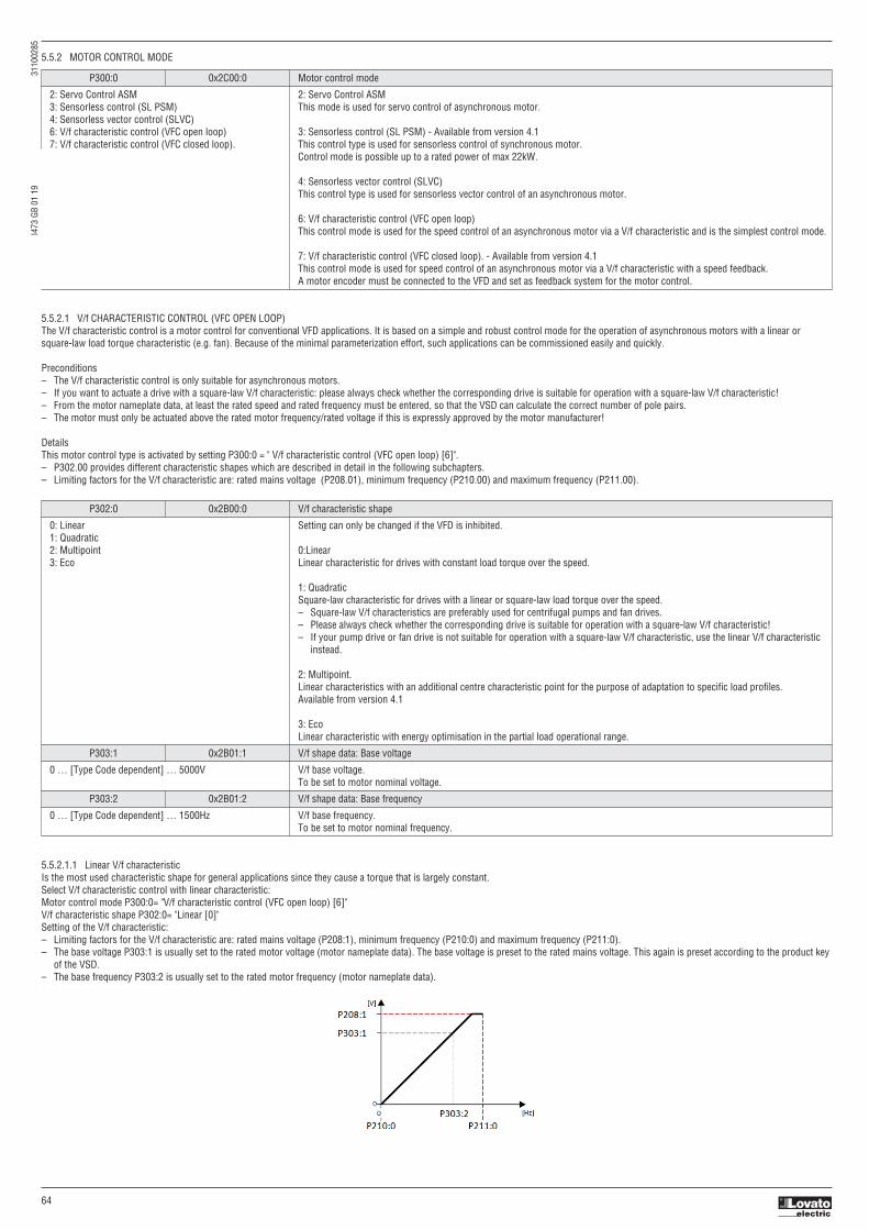
I473
GB
01 1
9
3
1100
285
64
5.5.2 MOTOR CONTROL MODE
P300:0 0x2C00:0 Motor control mode
2: Servo Control ASM 2: Servo Control ASM 3: Sensorless control (SL PSM) This mode is used for servo control of asynchronous motor. 4: Sensorless vector control (SLVC) 6: V/f characteristic control (VFC open loop) 3: Sensorless control (SL PSM) - Available from version 4.1 7: V/f characteristic control (VFC closed loop). This control type is used for sensorless control of synchronous motor. Control mode is possible up to a rated power of max 22kW.
4: Sensorless vector control (SLVC) This control type is used for sensorless vector control of an asynchronous motor.
6: V/f characteristic control (VFC open loop) This control mode is used for the speed control of an asynchronous motor via a V/f characteristic and is the simplest control mode.
7: V/f characteristic control (VFC closed loop). - Available from version 4.1 This control mode is used for speed control of an asynchronous motor via a V/f characteristic with a speed feedback. A motor encoder must be connected to the VFD and set as feedback system for the motor control.
5.5.2.1 V/f CHARACTERISTIC CONTROL (VFC OPEN LOOP)The V/f characteristic control is a motor control for conventional VFD applications. It is based on a simple and robust control mode for the operation of asynchronous motors with a linear orsquare-law load torque characteristic (e.g. fan). Because of the minimal parameterization effort, such applications can be commissioned easily and quickly.
Preconditions– The V/f characteristic control is only suitable for asynchronous motors.– If you want to actuate a drive with a square-law V/f characteristic: please always check whether the corresponding drive is suitable for operation with a square-law V/f characteristic!– From the motor nameplate data, at least the rated speed and rated frequency must be entered, so that the VSD can calculate the correct number of pole pairs. – The motor must only be actuated above the rated motor frequency/rated voltage if this is expressly approved by the motor manufacturer!
DetailsThis motor control type is activated by setting P300:0 = " V/f characteristic control (VFC open loop) [6]".– P302.00 provides different characteristic shapes which are described in detail in the following subchapters.– Limiting factors for the V/f characteristic are: rated mains voltage (P208.01), minimum frequency (P210.00) and maximum frequency (P211.00).
P302:0 0x2B00:0 V/f characteristic shape
0: Linear Setting can only be changed if the VFD is inhibited. 1: Quadratic 2: Multipoint 0:Linear 3: Eco Linear characteristic for drives with constant load torque over the speed.
1: Quadratic Square-law characteristic for drives with a linear or square-law load torque over the speed. – Square-law V/f characteristics are preferably used for centrifugal pumps and fan drives. – Please always check whether the corresponding drive is suitable for operation with a square-law V/f characteristic! – If your pump drive or fan drive is not suitable for operation with a square-law V/f characteristic, use the linear V/f characteristic instead.
2: Multipoint. Linear characteristics with an additional centre characteristic point for the purpose of adaptation to specific load profiles. Available from version 4.1
3: Eco Linear characteristic with energy optimisation in the partial load operational range.
P303:1 0x2B01:1 V/f shape data: Base voltage
0 … [Type Code dependent] … 5000V V/f base voltage. To be set to motor nominal voltage.
P303:2 0x2B01:2 V/f shape data: Base frequency
0 … [Type Code dependent] … 1500Hz V/f base frequency. To be set to motor nominal frequency.
5.5.2.1.1 Linear V/f characteristicIs the most used characteristic shape for general applications since they cause a torque that is largely constant.Select V/f characteristic control with linear characteristic:Motor control mode P300:0= "V/f characteristic control (VFC open loop) [6]"V/f characteristic shape P302:0= "Linear [0]"Setting of the V/f characteristic:– Limiting factors for the V/f characteristic are: rated mains voltage (P208:1), minimum frequency (P210:0) and maximum frequency (P211:0).– The base voltage P303:1 is usually set to the rated motor voltage (motor nameplate data). The base voltage is preset to the rated mains voltage. This again is preset according to the product key
of the VSD. – The base frequency P303:2 is usually set to the rated motor frequency (motor nameplate data).

I473
GB
01 1
9
3
1100
285
65
5.5.2.1.2 Square-law V/f characteristicThis is typically used in heating, ventilation and climate applications to control the speed of fans and pumps.
Each application that is provided with the features according to the affinity laws may possibly benefit from a square-law V/f characteristic.The affinity laws describe the relation between the speed and other variables:– The volume flow increases proportionately to the speed.– The required pressure behaves proportionately to the square of the speed.– The power input is proportionately to the cube of the speed. This means that already a minimal reduction of the speed may lead to substantial savings in energy consumption.
5.5.2.1.3 Multipoint user-definable V/f characteristic It is based on the linear V/f characteristic. An additional medium characteristic point, however, enables the adaptation to applications with special torque properties.
An application case for this characteristic shape are applications that require a higher torque at lower speeds. The additional medium characteristic point can be then configured in such a way thatmore voltage is provided in the lower frequency range of the characteristic. Otherwise, the same limits apply for the adaptive characteristic as for the linear characteristic.Select V/f characteristic control with adaptive characteristic:Motor control mode (P300:0) = "V/f characteristic control (VFC open loop) [6]"V/f characteristic shape (P302:0) = "Multipoint [2]"Setting of the V/f characteristic:– Limiting factors for the V/f characteristic are rated mains voltage (P208:01), minimum frequency (P210:00) and maximum frequency (P211:00).– The base voltage (P303:01) is usually set to the rated motor voltage (motor nameplate data). The base voltage is preset to the rated mains voltage. This again is preset according to the product
key of the VSD. – The base frequency (P303.02) is usually set to the rated motor frequency (motor nameplate data).– The additional medium characteristic point is defined based on the parameters P303:3 and P303:4.
By approximation, the square-law V/f characteristic corresponds to the curve for power input shown above. At low frequencies, the voltage is reduced since due to the type of load a lower voltage issufficient to generate the required power. All in all, this results in an energy-efficient system.Select V/f characteristic control with square-law characteristic:– Motor control mode P300:0 = "V/f characteristic control (VFC open loop) [6]"– V/f characteristic shape P302:0 = "Quadratic [1]"Setting of the V/f characteristic:– Limiting factors for the V/f characteristic are rated mains voltage (P208:1), minimum frequency (P210:0) and maximum frequency (P211:0).– The base voltage (P303:1) is usually set to the rated motor voltage (motor nameplate data). The base voltage is preset to the rated mains voltage. This again is preset according to the product
key of the VSD. – The base frequency (P303:2) is usually set to the rated motor frequency (motor nameplate data).
P303:3 0x2B01:3 V/f shape data: Midpoint voltage
0 … [0] … 5000V Definition of the voltage of medium characteristic point for user-definable V/f characteristic. Only relevant if P302:0=”Multipoint [2]”. Available from version 4.1
P303:4 0x2B01:4 V/f shape data: Midpoint frequency
0 … [0] … 1500Hz Definition of the frequency of medium characteristic point for user-definable V/f characteristic. Only relevant if P302:0=”Multipoint [2]”. Available from version 4.1

I473
GB
01 1
9
3
1100
285
66
5.5.2.1.4 Energy-saving V/f characteristic - (VFC Eco)With ECO mode the motor voltage of the VSD is detected by means of a linear characteristic as a function of the rotating field frequency or motor speed to be generated. Moreover, the motor isalways driven in the optimal efficiency range via a cosϕ control and the resulting voltage reduction (reduced copper losses in the asynchronous motor).
Select energy-saving V/f characteristic control with linear characteristic:Motor control mode P300:0 = "V/f characteristic control (VFC open loop) [6]"V/f characteristic shape P302:0 = "Eco [3]"
Setting of the V/f characteristic:– Limiting factors for the V/f characteristic are: rated mains voltage (P208:1), minimum frequency (P210:0) and maximum frequency (P211:0).– The base voltage (P303:1) is usually set to the rated motor voltage (motor nameplate data). The base voltage is preset to the rated mains voltage. This again is preset according to the product
key of the VSD. – The base frequency (P303:2) is usually set to the rated motor frequency (motor nameplate data).
Eco efficiency range:– The Eco efficiency range (grey) is between the V/f-standard characteristic (black) and the V/f Eco characteristic (green).– The V/f Eco characteristic (green) is defined by the operating point that results from the minimum voltage (P330:1) and the base frequency (P303:2).– The minimum voltage (P330:1) has to be set in percent with reference to the base voltage (P303:1).
5.5.2.2 V/f CHARACTERISTIC CONTROL (VFC CLOSED LOOP)The V/f characteristic control with feedback (VFC closed loop) can be used if an asynchronous motor with motor encoder is connected to the VSD.The speed feedback leads to the following advantages:– Stationary speed accuracy– Improved dynamics compared to the V/f characteristic control without feedback (VFC open loop) or to the encoderless vector control (SLVC)– Suitability for group drivesPreconditions– The V/f characteristic control (VFC closed loop) is only suitable for asynchronous motors.– The V/f characteristic control (VFC closed loop) requires a feedback of the speed. A motor encoder must be connected to the VSD and set as feedback system for the motor control.– For required settings see chapter “HTL encoder setup”.– If you want to actuate a drive with a square-law V/f characteristic: please always check whether the corresponding drive is suitable for operation with a square-law V/f characteristic!– From the motor nameplate data, at least the rated speed and rated frequency must be entered, so that the VSD can calculate the correct number of pole pairs.– The motor must only be actuated above the rated motor frequency/rated voltage if this is expressly approved by the motor manufacturer!
This motor control type is activated by setting P300:0 = " V/f characteristic control (VFC closed loop) [7]".– P302:0 provides different characteristic shapes.– Limiting factors for the V/f characteristic are rated mains voltage (P208:1), minimum frequency (P210:0) and maximum frequency (P211:0).– The slip compensation is deactivated in this motor control type. In case of V/f characteristic control with feedback, the slip is calculated and injected by the slip regulator.
5.5.2.3 SENSORLESS VECTOR CONTROL (SLVC)Sensorless (field-oriented) vector control for asynchronous motors is based on a decoupled, separate control for the torque-producing and the field-producing current component. In addition, theactual speed is reconstructed by means of a motor model so that a speed sensor is not required.Preconditions– Sensorless vector control (SLVC) is only suitable for asynchronous motors.– Operation of the sensorless vector control (SLVC) is only permissible for one single drive!– Operation of the sensorless vector control (SLVC) is not permissible for hoists!Supported operating modes (P301:0):– "MS: Velocity mode [-2]"– "MS: Torque mode [-1]"– "CiA: Velocity mode [2]"
This motor control type is activated by setting P300:0 = " Sensorless vector control (SLVC) [4]".Compared to the V/f characteristics, the sensorless vector control (SLVC) serves to achieve improved drive characteristics thanks to:– higher torque throughout the entire speed range– higher speed accuracy and higher concentricity factor– higher efficiency
P330:1 0x2B0D:1 VFC-ECO: Minimum voltage
20 … [20] … 100% Defining the operating point of the V/f ECO characteristic. The V/f ECO characteristic defines the lower limit of the eco efficiency range. 100% = Base voltage (P303:1).

I473
GB
01 1
9
3
1100
285
67
For a speed control with torque limitation in operating mode P301:0 = "MS: Velocity mode [-2]":1. Select the source in P337:1 for the positive torque limit source and set it accordingly.2. Select the source in P337:2: for the negative torque limit source and set it accordingly.Alternatively, the VSD can be configured in this motor control type in such a way that it controls a motor torque within a defined frequency range. For details, see chapter "Torque control w/ freq.limit".
P337:1 0x2949:1 Positive torque limit source
0: Max torque Selection of the source of positive torque limit. 1: Fixed limit 0.0% Available from version 4.1 2: Analog input 1 3: Analog input 2 0: Max torque 4: Positive torque limit Positive torque limit source = max torque (P326:0). 5: Network target torque 1: Fixed limit 0.0% Positive torque limit source = 0.0%
2: Analog input 1 The positive torque limit source is defined as analog signal via the analog input 1.
3: Analog input 2 The positive torque limit source is defined as analog signal via the analog input 2.
4: Positive torque limit Positive torque limit = Positive torque limit 0x60E0
5: Network target torque The positive torque limit source is defined as process data object via network.
P337:2 0x2949:2 Negative torque limit source
0: Max torque Selection of the source of negative torque limit. 1: Fixed limit 0.0% Available from version 4.1 2: Analog input 1 3: Analog input 2 0: Max torque 4: Negative torque limit Negative torque limit source = max torque (P326:0). 5: Network target torque 1: Fixed limit 0.0% Negative torque limit source = 0.0%
2: Analog input 1 The negative torque limit source is defined as analog signal via the analog input 1.
3: Analog input 2 The negative torque limit source is defined as analog signal via the analog input 2.
4: Negative torque limit Negative torque limit = Negative torque limit 0x60E1
5: Network target torque The negative torque limit source is defined as process data object via network.
P301:0 0x6060 Modes of operation
-2: MS: Velocity mode Selection of the operating mode. -1: MS: Torque mode 0: No mode change / no mode assigned -2: MS: Velocity mode 2: CiA: Velocity mode Vendor specify velocity mode.
-1: MS: Torque mode Vendor specify torque mode. Only possible in motor control type P300:0=”Sensorless vector control (SLVC) [4]” Available from version 4.1
0: No mode change / no mode assigned No operating mode (standstill).
2: CiA: Velocity mode CiA402 velocity mode.

I473
GB
01 1
9
3
1100
285
68
5.5.2.4 Servo control for asynchronous motors (SC-ASM)The field-oriented servo control is based on a decoupled, separated control of the torque-producing and field-producing current share. The motor control is based on a feedback, field-orientedand cascaded controller structure and enables a dynamic and stable operation in all four quadrants.
Preconditions– The servo control (SC ASM) is only suitable for asynchronous motors.– The servo control (SC ASM) is possible up to a rated power of maximally 45 kW.– The servo control (SC-ASM) requires a feedback of the speed. A motor encoder must be connected to the VSD and set as feedback system for the motor control.– For required settings see chapter "HTL encoder setup".
DetailsThis motor control type is activated by setting P300:0 = " Servo control (SC ASM)[2]".Basically, the servo control has the same advantages as the sensorless vector control (SLVC).Compared to the V/f characteristic control without feedback, the following can be achieved by means of the servo control:– A higher maximum torque throughout the entire speed range– A higher speed accuracy– A higher concentricity factor– A higher level of efficiency– The implementation of torque-actuated operation with speed limitation– The limitation of the maximum torque in motor and generator mode for speed-actuated operationFor a speed control with torque limitation in operating mode P301:0= "MS: Velocity mode [-2]":1. Select the source in P337:01 for the positive torque limit source and set it accordingly.2. Select the source in P337:02 for the negative torque limit source and set it accordingly.
5.5.2.5 Sensorless control for synchronous motors (SL-PSM)The sensorless control for synchronous motors is based on a decoupled, separated control of the torque-producing current and the current in field direction. In contrast to the servo control,the actual speed value and rotor position are reconstructed via a motor model.
NOTICEIn case of this motor control type, an adjustable, constant current is injected in the lower speed range. If this current is higher than the rated motor current, the motor may heat up inthe lower speed range. This effect increases if the motor is operated in the lower speed range for a longer period of time.Possible consequence: Destruction of the motor by overheating
Do not operate the motor for a longer period of time in the lower speed range.
For detecting and monitoring the motor temperature, we recommend a temperature feedback via PTC thermistor or thermal contact.
PreconditionsThe sensorless control for synchronous motors (SL-PSM) is possible up to a rated power of max 22kW.
This motor control type is activated by setting P300:0 = " Sensorless control (SLPSM) [3]".The motor model-based speed observer requires a rotating machine. Thus, as a matter of principle, the operational performance of the sensorless control for synchronous motors is divided intotwo ranges:1. Low speed range (|setpoint speed| < lower limit 0x2C11:001)– In the range of low speed, the speed of a synchronous motor cannot be observed. In this "Low speed range", an open-loop controlled operation takes place: For acceleration processes, the
current set in 0x2C12:001 is injected and for processes without acceleration (for instance standstill or constant setpoint speed) the current set in 0x2C12:002 is injected.2. High speed range (|setpoint speed| > lower limit 0x2C11:001)– In this area, the rotor flux position and the speed are reconstructed by means of an observer. The control is executed in a field-oriented way. Only the current required for generating the
necessary torque is injected.
Pole position identification (PLI)– For controlling a permanent-magnet synchronous motor, the pole position - the angle between the motor phase U and the field axis of the rotor - must be known.– In case of a drive at standstill, the VSD enable is directly followed by the "pole position identification (PLI)" which identifies the initial pole position.
Flying restart circuit– From firmware version 4.1 onwards, a flying restart circuit for the synchronous motor up to speeds lower than half the rated speed is supported.– If the flying restart circuit shall be used, set the start method "Flying restart circuit [2]" in P203:1. More settings are not required for the flying restart circuit at sensorless control of a
synchronous motor.
For a speed control with torque limitation in operating mode P301:0 = "MS: Velocity mode [-2]":1. Select the source in P337:1 for the positive torque limit source and set it accordingly.2. Select the source in P337:2 for the negative torque limit source and set it accordingly.
SL-PSM parametersThe parameters for this motor control type are calculated and set automatically while optimizing the control loops.
P352:1 0x2C03:1 Back EMF constant (BEMF constant)
0.0 ... [41.8] ... 100000.0 V/1000rpm Voltage induced by the motor (rotor voltage / 1000 rpm).
0x2C11:1 High speed range: Lower limit
5 ... [30] ... 100 % Definition of the lower limit of the high speed range. – The lower limit has a permanent hysteresis of 5 %.
0x2C11:2 High speed range: Tracking controller gain
0 ... [200] ... 65535 % Gain factor for tracking the rotor position in the motor model.
0x2C11:3 High speed range: Tracking controller reset time
0.00 ... [6.00] ... 655.35 ms Reset time for tracking the rotor position in the motor model.
0x2C11:4 High speed range: Tracking controller decouple time
0.0 ... [200.0] ... 6553.5 ms Temporal hysteresis for the switching back and forth from the open-loop controlled to the closed-loop controlled operation.
0x2C12:1 SM low speed range: Acceleration current
5 ... [70] ... 400 % R.m.s. current value for acceleration processes in the lower velocity range. – 100 % ≡ rated motor current (P323:0). – In case of a "100 %" setting and at standstill, a motor current flows that is square root of 2 higher than the rated current. But as soon as the motor rotates, the effective rated current flows.
0x2C12:2 SM low speed range: Standstill current
5 ... [40] ... 400 % R.m.s. current value for processes without acceleration (for instance standstill or constant setpoint speed) in the lower velocity range. – 100 % ≡ rated motor current (P323:0)

I473
GB
01 1
9
3
1100
285
69
5.5.2.5.1 Stall monitoringThe stalling monitoring for the sensorless control for synchronous motors (SL-PSM) switches off the drive if the motor is about to "stall". A possible cause may be an overload of the motor.PreconditionsThe stalling monitoring only works in the controlled area and if the motor is not operated in the field weakening range.
In order to detect the motor stalling, the cosine phi is used.Example:– For the cosine phi, the value "0.9" is set in P320:08 according to the data given on the motor nameplate.– The limit value for stalling monitoring is set in 0x2C11:006 to "80 %".– Stalling monitoring is triggered if the current cosine phi is lower than 0.72 (80 % of 0.9).
If stalling monitoring is triggered, the "Trouble" error response takes place. If the operating mode "MS: Velocity mode [-2]" is set in P301:0, the motor automatically restarts if the trouble does notexist anymore.
5.5.3 OPTIMISATION OF MOTOR CONTROLThe VSD provides different functions by means of which the drive behaviour can be further optimised.
Function Motor control type
VFC open loop VFC closed loop SC-ASM SL-PSM SLVC
V/f voltage boost
The parameterisable voltage boost makes it possible to improve the starting performace for applications requiring a high starting torque
Skip frequencies By means of three parameterisable skip frequencies, critical frequencies can be
suppressed which lead to mechanical resonances in the system
Optimising the stalling behaviour
For special motors which enable an operation in the field weakening range, the behaviour in the field weakening range can be adapted to the motor
Slip compensation In case of a load, the speed of an asynchronous motor decreases. This load-dependent speed drop is called slip. The slip compensation serves to counteract the load-dependent speed loss
Oscillation damping
The oscillation damping serves to reduce the oscillations during no-load operation which are caused by energy oscillating between the mechanical system (mass inertia) and the electrical system (DC bus)
Synchronous motor: Pole position identification (PPI) For controlling a permanent-magnet synchronous motor, the pole position - the angle between the motor phase U and the field axis of the rotor - must be known. This function serves to detect the pole position for the currently activated motor encoder
VFC open loop = V/f characteristic control VFC closed loop = V/f characteristic control with speed feedback SC-ASM = servo control for asynchronous motor SL-PSM = sensorless control for synchronous motor SLVC = sensorless vector control
5.5.3.1 V/f voltage boostThe voltage boost makes it possible to improve the starting performance for applications requiring a high starting torque.
PreconditionsThe function is only effective in the following motor control types:– V/f characteristic control (VFC open loop)– V/f characteristic control (VFC closed loop)Details– In P316:1 a permanent voltage boost can be set. ①– In P316:2 an additional voltage boost can be set for acceleration processes only. ②– Reference for the percentage setting of the voltage boost is the base voltage P303:1.
P316:1 0x2B12:1 Fixed boost
0.0 ... [Type Code dependent] ... 20.0 % Fixed (constant) voltage boost for V/f characteristic control without feedback. – 100 % ≡ V/f base voltage (P303.01) – For the purpose of optimising the starting performance for applications requiring a high starting torque.
P316:2 0x2B12:2 V/f voltage boost: Boost at acceleration
0.0 ... [0.0] ... 20.0 % Additional voltage boost for V/f characteristic control without feedback. – 100 % ≡ V/f base voltage (P303:1) – This voltage boost is only active while the motor is accelerated. It then acts in addition to the fixed voltage boost set in P316:1.

I473
GB
01 1
9
3
1100
285
70
5.5.3.2 Skip frequenciesBy means of the three skip frequencies, critical frequencies can be suppressed which lead to mechanical resonances in the system.
A blocking zone is active as soon as the frequency for this blocking zone is set to value unequal to "0 Hz".– The set frequency defines the centre of the range to be masked out. ①– The set bandwidth defines its total size. ②
Example: For a blocking zone, the frequency is set to 20 Hz and the bandwidth to 10 Hz.These settings mask out the range from 15 Hz to 25 Hz.Notes:– Skip frequencies are absolute values. With the setting "20 Hz", at the same time also the skip frequency "-20 Hz" is defined.– The VSD accelerates/decelerates the motor by the range to be masked out. A continuous operation within this range is not possible.– A blocking zone is not active if its bandwidth is set to "0 Hz".
Adjacent and overlapping ranges:– Example on the left: If the ranges are closely spaced, the ranges are passed through as shown.– Example on the right: If the ranges overlap, the lowest and highest value form a new range.
Valid and invalid ranges:– Example on the left: Skip frequency = 5 Hz, bandwidth = 10 Hz → Valid range (starts at ≥ 0)– Example on the right: Skip frequency = 4 Hz, bandwidth = 10 Hz → Invalid range (starts at < 0); is thus ignored.
P317:1 0x291F:1 Skip frequency 1
0.0 ... [0.0] ... 599.0 Hz Centre of frequency range 1 which is to be skipped.
P317:2 0x291F:2 Skip bandwidth 1
0.0 ... [0.0] ... 10.0 Hz Size of frequency range 1 which is to be skipped.
P317:3 0x291F:3 Skip frequency 2
0.0 ... [0.0] ... 599.0 Hz Centre of frequency range 2 which is to be skipped.
P317:4 0x291F:4 Skip bandwidth 2
0.0 ... [0.0] ... 10.0 Hz Size of frequency range 2 which is to be skipped.
P317:5 0x291F:5 Skip frequency 3
0.0 ... [0.0] ... 599.0 Hz Centre of frequency range 3 which is to be skipped.
P317:6 0x291F:6 Skip bandwidth 3
0.0 ... [0.0] ... 10.0 Hz Size of frequency range 3 which is to be skipped.
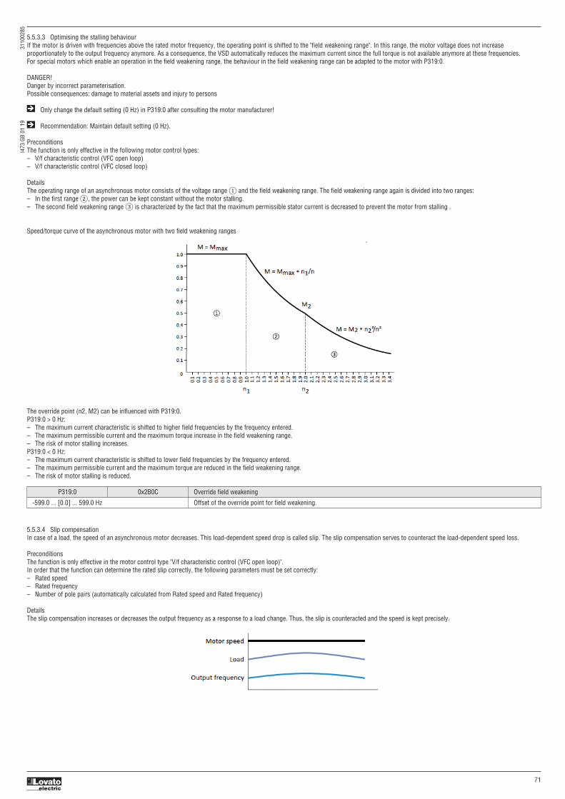
I473
GB
01 1
9
3
1100
285
71
5.5.3.3 Optimising the stalling behaviourIf the motor is driven with frequencies above the rated motor frequency, the operating point is shifted to the "field weakening range". In this range, the motor voltage does not increaseproportionately to the output frequency anymore. As a consequence, the VSD automatically reduces the maximum current since the full torque is not available anymore at these frequencies.For special motors which enable an operation in the field weakening range, the behaviour in the field weakening range can be adapted to the motor with P319:0.
DANGER!Danger by incorrect parameterisation.Possible consequences: damage to material assets and injury to persons
Only change the default setting (0 Hz) in P319:0 after consulting the motor manufacturer!
Recommendation: Maintain default setting (0 Hz).
PreconditionsThe function is only effective in the following motor control types:– V/f characteristic control (VFC open loop)– V/f characteristic control (VFC closed loop)
DetailsThe operating range of an asynchronous motor consists of the voltage range ① and the field weakening range. The field weakening range again is divided into two ranges:– In the first range ②, the power can be kept constant without the motor stalling.– The second field weakening range ③ is characterized by the fact that the maximum permissible stator current is decreased to prevent the motor from stalling .
Speed/torque curve of the asynchronous motor with two field weakening ranges
The override point (n2, M2) can be influenced with P319:0.P319:0 > 0 Hz:– The maximum current characteristic is shifted to higher field frequencies by the frequency entered.– The maximum permissible current and the maximum torque increase in the field weakening range.– The risk of motor stalling increases.P319:0 < 0 Hz:– The maximum current characteristic is shifted to lower field frequencies by the frequency entered.– The maximum permissible current and the maximum torque are reduced in the field weakening range.– The risk of motor stalling is reduced.
5.5.3.4 Slip compensationIn case of a load, the speed of an asynchronous motor decreases. This load-dependent speed drop is called slip. The slip compensation serves to counteract the load-dependent speed loss.
PreconditionsThe function is only effective in the motor control type "V/f characteristic control (VFC open loop)".In order that the function can determine the rated slip correctly, the following parameters must be set correctly:– Rated speed– Rated frequency– Number of pole pairs (automatically calculated from Rated speed and Rated frequency)
DetailsThe slip compensation increases or decreases the output frequency as a response to a load change. Thus, the slip is counteracted and the speed is kept precisely.
P319:0 0x2B0C Override field weakening
-599.0 ... [0.0] ... 599.0 Hz Offset of the override point for field weakening.

I473
GB
01 1
9
3
1100
285
72
The rated slip required for the slip compensation is calculated by the VSD according to the following formula:Rated slip [%] = (1 - (rated motor speed [rpm] / (120 * rated motor frequency [Hz] / number of poles))) * 100Calculation example:– Rated motor speed = 1750 rpm– Rated motor frequency = 60 Hz– Number of poles = 2 * Number of pole pairs = 2 * 2 = 4– Rated slip = (1 - (1750 / (120 * 60 / 4))) * 100 = 2.77 %The rated slip represents the reduction of the motor speed due to the motor load. At full speed and full load, the motor given in the example would rotate with 1750 rpm, which means 2.77 %below its synchronous speed of 1800 rpm. In order to compensate this speed loss, the VSD increases the output frequency by the rated slip multiplied by the rated motor frequency. In the example2.77 % * 60 Hz = 1.66 Hz increase at full load.In order to consider load changes, the influence of the rated slip on output frequency can be adapted in P315:1. A setting of 100 % corresponds to the rated slip of the machine in the nominaloperating point.With reference to the example above and a setpoint frequency of 60 Hz:– P315:1 = 100 %, the output frequency is = 61.66 Hz (60 Hz + 100 % * 1.66 Hz).– P315:1 = 50 %, the output frequency is = 60.83 Hz (60 Hz + 50 % * 1.66 Hz).Additionally, the filter time for the slip compensation can be adapted in P315:2 if required. The preset filter time is adapted to typical motors. If full load or nearly full load oscillations or instabilitiesoccur, we recommend an increase of the filter time.
5.5.3.5 Oscillation dampingThe oscillation damping serves to reduce the oscillations during no-load operation which are caused by energy oscillating between the mechanical system (mass inertia) and the electrical system(DC bus). Furthermore, the oscillation damping can also be used to compensate for resonances.
PreconditionsThe function is only effective in the following motor control types:– V/f characteristic control (VFC open loop)– V/f characteristic control (VFC closed loop)
RestrictionsObserve the following restrictions:– Damping is possible only for constant oscillations at a steady-state operating point.– Oscillations occurring sporadically cannot be damped.– Oscillation damping is not suitable for oscillations occurring during dynamic processes (e.g. accelerations or load changes).– Oscillation damping is only active if the setpoint speed is greater than 10 rpm and the DC bus voltage exceeds a value of 100 V.
DetailsThe determination of the oscillation is based on the active current. In order to obtain the alternating component of the active current, this current is differentiated. This signal is then passed througha PT1 filter.
Identification of the oscillationBefore the oscillation damping function can be parameterised, the oscillation has to be identified.One way to do this is to examine the motor current while oscillation damping is switched off (gain = 0 %). At steady-state operation, a constant current flows. If the drive oscillates, theseoscillations are also visible on the motor current. It is therefore possible to determine the frequency and the amplitude of the oscillation from the alternating component of the motor current. In thefollowing, this alternating component is referred to as "current oscillation".
Parameter settingThe gain of the oscillation signal is to be set according to the following equation:P318:1 = current amplitude * 100 % / (√2* maximum device current)The default time constant of the PT1 filter should be sufficient for most applications. If required, it is only possible to adapt the time constant via VLBXSW01 Generally, the time constant must be set so that the oscillation can be dampened, but that higher-frequency components are filtered from the signal. The time constant is determined from thereciprocal value of the double current oscillation frequency:P318:2 = 1 / (2 * oscillation frequency)
P315:1 0x2B09:1 Slip compensation: Gain
-200.00 ... [100.00] ... 200.00 % Adjustment in percent of the slip calculated. – For instance required for deviations of the real motor data from the nameplate data. – A setting of 100 % corresponds to the rated slip of the machine in the nominal operating point.
P315:2 0x2B09:2 Slip compensation: Filter time
1 ... [5] ... 6000 ms Filter time for the slip compensation. – The preset filter time is adapted to typical motors.
P351:4 0x2C02:4 Slip frequency
Read only: x.x Hz Display of the rated slip determined.
P318:1 0x2B0A:1 Gain
-100 ... [20] ... 100 % Gain of the oscillation signal. • With the setting 0, oscillation damping is deactivated.
P318:2 0x2B0A:2 Filter time
1 ... [5] ... 600 ms Time constant of the PT1 filter.
5.5.4 OPTIMISATION OF THE CONTROL LOOPSIf there is a need to improve the total power of the system, different options are available:a) Tuning of the motor and the speed controllerb) Automatic motor identification (energized)c) Automatic motor calibration (non-energized)Simply select an option that best suits your environment and requirements!
5.5.4.1 Options for optimized motor tuningThe option to be selected depends on the respective application. Depending on the selected option, different procedures become active and thus different parameter groups are influenced:– Rated motor data– VSD characteristic– Motor equivalent circuit diagram data– Motor controller settings– Speed controller settings.

I473
GB
01 1
9
3
1100
285
73
5.5.4.1.1 Tuning of the motor and the speed controllerThe following describes in general how to optimise the speed controller. This may be required if some parameters have on the load side of the drive system have changed or have not been set yet,such as:– Motor moment of inertia– Load moment of inertia– Type of coupling between moment of inertia of the motor and that of the load.
Preconditions– All rated motor data are known and set in the VSD (see chapter “motor data”).– All further options for optimisation have been executed before if possible. • Automatic motor identification (energized) • Automatic motor calibration (non-energized) – Optimisation is possible online or offline (with or without connected motor).
Required stepsAdapt the following parameters to your drive system using the engineering tool. Since this only changes load-dependent data, the other parameter groups must not be calculated again.
5.5.4.1.2 Automatic motor identification (energized)The automatic identification of the motor results in the best possible parameter settings. If the application enables you to energise the system during the optimisation, carry out this optimisation.
Preconditions– The motor must be cold.– All rated motor data are known and set in the VSD.– In P300:0 the motor control type required and suitable for the motor is selected.– In P301:0 the operating mode "MS: Velocity mode [-2]" or "CiA: Velocity mode [2]" is set.– DC-bus voltage is available.– The VSD is error-free and in the "Ready to switch on" or "Switched on" device state.– The motor is stopped (no start enable).– No VSD disable is active.– No quick stop is active.– No other axis command is active anymore.
General information on the identification– The automatic identification can take from some seconds to minutes.– The procedure can be aborted any time by VSD disable or cancellation of the start enable without settings being changed.– During and after the procedure, the LED "RDY" (blue) is permanently on.– After completing, a renewed start command is required to start the motor.
Required stepsSet P327:4 = "1".Issue the start command to start the procedure.
Optimisation processAs soon as the process has been started, the following steps are initiated:1. The VSD characteristic is automatically identified by the VSD.2. The motor equivalent circuit diagram data are automatically identified by the VSD.3. The motor controller settings are automatically calculated.4. The speed controller settings are automatically calculated
5.5.4.1.3 Automatic motor calibration (non-energized)If the application does not enable you to energise the system during the optimisation, carry out this optimisation.
Preconditions– All rated motor data are known and set in the VSD.– In P300:0 the motor control type required and suitable for the motor is selected.– The VSD is error-free and in the "Ready to switch on" or "Switched on" device state.– The VSD is disabled or the motor is stopped (no start enable).– No other axis command is active anymore.
Required stepsSet P327:5 = "1" to start the process.
P335:1 0x2910:1 Motor moment of inertia
0.00 ... [Type code dependent] ... 20000000.00 kg cm² Setting of the moment of inertia of the motor.
P335:2 0x2910:2 Load moment of inertia
0.00 ... [ Type code dependent ] ... 20000000.00 kg cm² Setting of the moment of inertia of the load. – Always adjust the setting to the current load, otherwise the optimization process cannot be executed successfully.
- 0x2910:3 Coupling
0: Stiff Selection of the type of coupling between the moment of inertia of the motor and that of the load. 1: Elastic 2: With backlash
- 0x2904 Actual speed filter time
0.0 ... [2.0] ... 50.0 ms Filter time for the actual speed value.
P327:4 0x2822:4 Identify motor data (energized)
0 ... [0] ... 1 1 = start automatic identification of the motor data. – VSD characteristics, motor equivalent circuit diagram data and controller settings are identified and set automatically. – During the procedure, the motor is energised!
P327:5 0x2822:5 Calibrate motor data (non-energized)
0 ... [0] ... 1 1 = start automatic calibration of the motor data. – A default VSD characteristic is loaded. – The motor equivalent circuit diagram data and controller settings are calculated on the basis of the currently set rated motor data. – The motor is not energised.

I473
GB
01 1
9
3
1100
285
74
Optimisation processAs soon as the process has been started, the following steps are initiated:1. A default VSD characteristic is loaded.2. The motor equivalent circuit diagram data is calculated based on the currently set rated motor data.3. The motor controller settings are automatically calculated.4. The speed controller settings are automatically calculated.
5.5.4.2 Motor equivalent circuit diagram dataThe motor equivalent circuit diagram data are automatically set if one of the following optimizations is carried out:– Automatic motor identification (energized) – Automatic motor calibration (non-energized).
5.5.4.3 Motor controller settingsAfter the motor settings have been made, the different control loops must be set. For a quick commissioning, the calculations and settings are made automatically if one of the followingoptimisations is carried out:– Automatic motor identification (energized) – Automatic motor calibration (non-energized)
DetailsThe following controllers have an influence in the respective motor control type:
5.5.4.3.1 Current controllerFor a quick commissioning, the calculations and settings are made automatically during the optimisation.
For typical applications, a manual adaptation of the parameters of the current controller is not recommended. A wrong setting may have a negative effect on the control. For special applications, contact the manufacturer before adapting the parameters.
PreconditionsThe current controller parameters are calculated based on the stator resistance and leakage inductance. Thus, the following parameters must be set correctly, either via optimisation or manually(according to manufacturer-data/motor data sheet):– 0x2C01:2: Stator resistance– 0x2C01:3: Stator leakage inductance
i
5.5.4.3.2 Field controllerFor a quick commissioning, the calculations and settings are made automatically during the optimisation.
The field controller is only effective in the following motor control types:– Servo control (SC ASM)– Sensorless vector control (SLVC)
For the manual adaptation of the parameters refer to the software VLBXSW01.
- 0x2C01:2 Motor parameters: Stator resistance
0.0000 ... [Type Code dependent] ... 125.0000 Ω Stator resistance General motor data. Carry out settings as specified by manufacturer data/motor data sheet.
- 0x2C01:3 Stator leakage inductance
0.000 ... [ Type Code dependent ]... 500.000 mH Stator leakage inductance General motor data. Carry out settings as specified by manufacturer data/motor data sheet.
P351:1 0x2C02:1 Motor parameter (ASM): Rotor resistance
0.0000 ... [ Type Code dependent ] ... 200.0000 Ω Rotor resistance Equivalent circuit data of the motor required for the motor model.
P351:2 0x2C02:2 Motor parameter (ASM): Mutual inductance
0.0 ... [ Type Code dependent ]... 50000.0 mH Mutual inductance Equivalent circuit data of the motor required for the motor model.
P351:3 0x2C02:3 Motor parameter (ASM): Magnetising current
0.00 ... [ Type Code dependent ] ... 500.00 A Magnetising current Equivalent circuit data of the motor required for the motor model.
Function Motor control type
VFC open loop VFC closed loop SC-ASM SL-PSM SLVC
Current controller
Field controller
Field weakening controller
Imax controller
Flying restart controller
SLVC controller
Slip controller
VFC open loop = V/f characteristic control VFC closed loop = V/f characteristic control with speed feedback SC-ASM = servo control for asynchronous motor SL-PSM = sensorless control for synchronous motor SLVC = sensorless vector control
P334:1 0x2942:1 Current controller parameters: Gain
0.00 ... [Type code dependent ] ... 750.00 V/A Gain factor Vp of the current controller.
P334:2 0x2942:2 Current controller parameters: Reset time
0.01 ... [Type code dependent ]... 2000.00 ms Reset time Ti of the current controller.
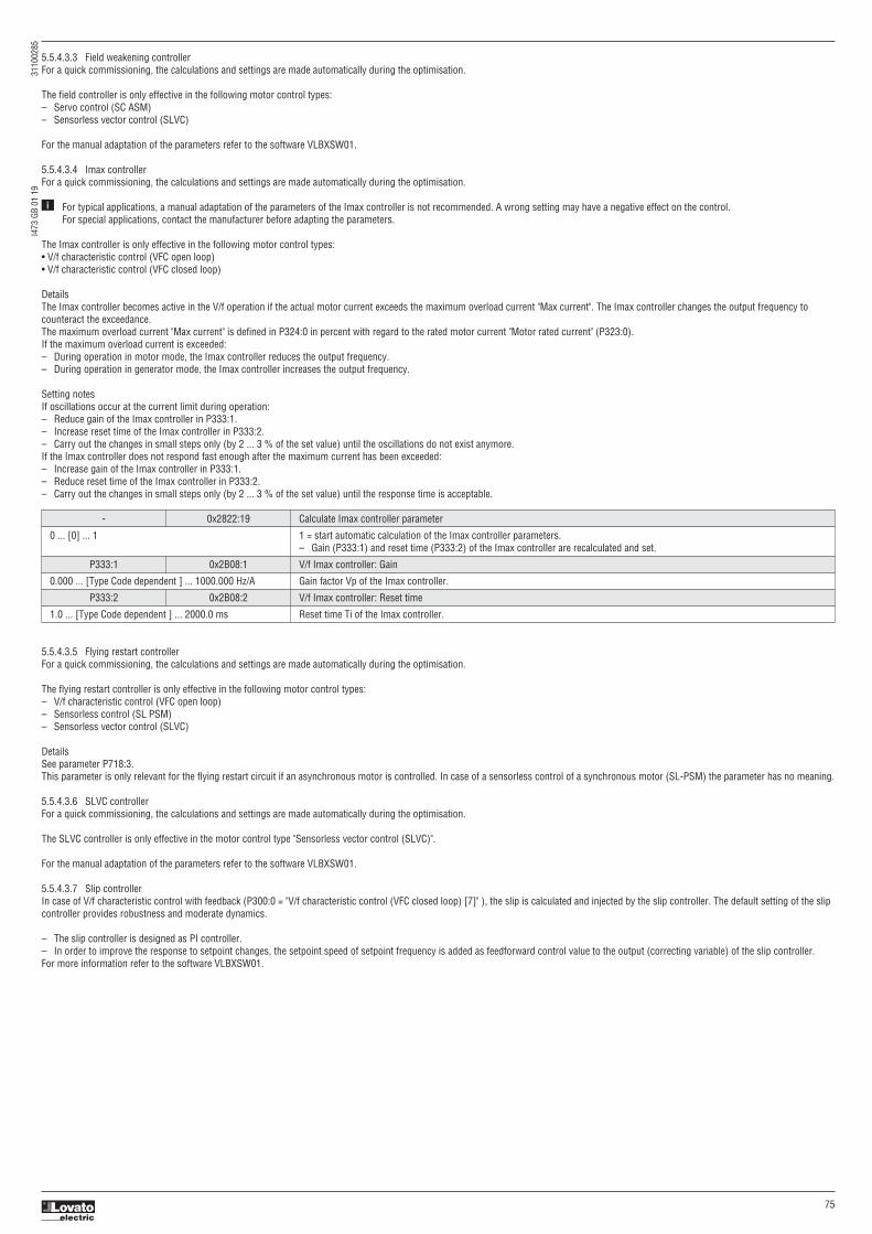
I473
GB
01 1
9
3
1100
285
75
5.5.4.3.3 Field weakening controllerFor a quick commissioning, the calculations and settings are made automatically during the optimisation.
The field controller is only effective in the following motor control types:– Servo control (SC ASM)– Sensorless vector control (SLVC)
For the manual adaptation of the parameters refer to the software VLBXSW01.
5.5.4.3.4 Imax controllerFor a quick commissioning, the calculations and settings are made automatically during the optimisation.
For typical applications, a manual adaptation of the parameters of the Imax controller is not recommended. A wrong setting may have a negative effect on the control. For special applications, contact the manufacturer before adapting the parameters.
The Imax controller is only effective in the following motor control types:• V/f characteristic control (VFC open loop)• V/f characteristic control (VFC closed loop)
DetailsThe Imax controller becomes active in the V/f operation if the actual motor current exceeds the maximum overload current "Max current". The Imax controller changes the output frequency tocounteract the exceedance.The maximum overload current "Max current" is defined in P324:0 in percent with regard to the rated motor current "Motor rated current" (P323:0).If the maximum overload current is exceeded:– During operation in motor mode, the Imax controller reduces the output frequency.– During operation in generator mode, the Imax controller increases the output frequency.
Setting notesIf oscillations occur at the current limit during operation:– Reduce gain of the Imax controller in P333:1.– Increase reset time of the Imax controller in P333:2.– Carry out the changes in small steps only (by 2 ... 3 % of the set value) until the oscillations do not exist anymore.If the Imax controller does not respond fast enough after the maximum current has been exceeded:– Increase gain of the Imax controller in P333:1.– Reduce reset time of the Imax controller in P333:2.– Carry out the changes in small steps only (by 2 ... 3 % of the set value) until the response time is acceptable.
i
- 0x2822:19 Calculate Imax controller parameter
0 ... [0] ... 1 1 = start automatic calculation of the Imax controller parameters. – Gain (P333:1) and reset time (P333:2) of the Imax controller are recalculated and set.
P333:1 0x2B08:1 V/f Imax controller: Gain
0.000 ... [Type Code dependent ] ... 1000.000 Hz/A Gain factor Vp of the Imax controller.
P333:2 0x2B08:2 V/f Imax controller: Reset time
1.0 ... [Type Code dependent ] ... 2000.0 ms Reset time Ti of the Imax controller.
5.5.4.3.5 Flying restart controllerFor a quick commissioning, the calculations and settings are made automatically during the optimisation.
The flying restart controller is only effective in the following motor control types:– V/f characteristic control (VFC open loop)– Sensorless control (SL PSM)– Sensorless vector control (SLVC)
DetailsSee parameter P718:3. This parameter is only relevant for the flying restart circuit if an asynchronous motor is controlled. In case of a sensorless control of a synchronous motor (SL-PSM) the parameter has no meaning.
5.5.4.3.6 SLVC controllerFor a quick commissioning, the calculations and settings are made automatically during the optimisation.
The SLVC controller is only effective in the motor control type "Sensorless vector control (SLVC)".
For the manual adaptation of the parameters refer to the software VLBXSW01.
5.5.4.3.7 Slip controllerIn case of V/f characteristic control with feedback (P300:0 = "V/f characteristic control (VFC closed loop) [7]" ), the slip is calculated and injected by the slip controller. The default setting of the slipcontroller provides robustness and moderate dynamics.
– The slip controller is designed as PI controller.– In order to improve the response to setpoint changes, the setpoint speed of setpoint frequency is added as feedforward control value to the output (correcting variable) of the slip controller.For more information refer to the software VLBXSW01.

I473
GB
01 1
9
3
1100
285
76
5.5.4.4 Speed controllerThe speed controller is automatically set if one of the following optimisations is carried out:– Automatic motor identification (energized) – Automatic motor calibration (non-energized).
For typical applications, a manual adaptation of the parameters of the speed controller is not recommended. A wrong setting may have a negative effect on the control. For special applications, contact the manufacturer before adapting the parameters.
The speed controller has an influence in the following motor control types:– Servo control (SC ASM)– Sensorless control (SL PSM)– Sensorless vector control (SLVC)The automatically calculated settings for the speed controller enable an optimal control behaviour for typical load requirements:– Minimum speed loss ①– Minimum settling time ②– Minimum overshoot ③
i
Setting notesIf oscillations occur during operation after high load requirements:– Reduce gain of the speed controller in P332:1.– Increase reset time of the speed controller in P332:2.If the speed loss is too high or the settling time too long during operation with high load requirements:– Increase gain of the speed controller in P332:1.
Note. If the gain is set too high or the reset time too low, the speed control loop can become unstable!
P332:1 0x2900:1 Speed controller settings: Gain
0.00000 ... [Type code dependent] ... 20000.00000 Nm/rpm Gain factor Vp of the speed controller.
P332:2 0x2900:2 Speed controller settings: Reset time
1.0 ... [Type code dependent ] ... 6000.0 ms Reset time Ti of the speed controller.
5.5.5 CONFIGURING THE TORQUE CONTROLIn general, the VSD is operated in a mode that controls the motor frequency. Alternatively, the VSD can be configured in such a way that it controls a motor torque within a defined frequency range.Typical applications for such a torque control with frequency limitation are winders and packaging machines.Torque control is available on VSD with firmware ≥4.1.
A torque control is only possible in the motor control type P300:0 = "Sensorless vector control (SLVC) [4]". After configuring the sensorless vector control (SLVC), one of the following optimisations must be carried out for a torque control as precise as possible:– Automatic motor identification (energized) – Automatic motor calibration (non-energized)
DetailsSetpoint selection:– Instead of a frequency setpoint in [Hz], a torque setpoint has to be defined for the torque control. This can be either a value in percent with reference to the rated motor torque set in P325:0 or a
value in [Nm] if defined via network.– The standard setpoint source for the torque control can be selected in P201:3 (default: Analog input 1).
Limitation of the torque range:– The positive and negative torque limit can be set independently of each other.
Frequency limitation / speed limitation:– The adjustable speed limits serve to protect against very high speeds. High speeds can occur if a pure torque is selected without a counter torque being available (load-free machine).– The torque control controls the assigned torque setpoint within the set speed limits. The actual speed results from the load conditions of the application. If the actual speed reaches the set speed
limits, it is kept on the respective limit value. This protective function is also called "speed limitation".– The lower and upper speed limit for speed limitation can be set independently of each other. They can also be defined via analog inputs or network.

I473
GB
01 1
9
3
1100
285
77
In the following, the steps required for configuring the torque control with frequency limitation are described.
Parameterisation required1. Set the operating mode "MS: Torque mode [-1]" in P301:0.2. Set the rated motor torque in P325:0.3. Set the permissible maximum torque in P326:0. – The setting is made in percent with reference to the rated motor torque set in P325:0.4. Select the source for the positive torque limit in P337:1. – Default setting: Maximum torque P326:0 – In case of selection "Analog Input 1 [2]": Set setting range in P430:11 and P430:12. – In case of selection "Analog Input 2 [3]": Set setting range in P431:11 and P431:12. – In case of selection "Positive torque limit [4]": Set the positive torque limit in 0x60E0.5. Select the source for the negative torque limit in P337:2. – Default setting: (-) Maximum torque P326:0. – In case of selection "Analog Input 1 [2]": Set setting range in P430:11 and P430:12. – In case of selection "Analog Input 2 [3]": Set setting range in P431:11 and P431:12. – In case of selection "Negative torque limit [4]": Set the negative torque limit in 0x60E1.6. Select the source for the upper speed limit in P340:3. – Default setting: Maximum frequency P211:0. – In case of selection "Analog Input 1 [2]": Set setting range in P430:2 and P430:3. – In case of selection "Analog Input 2 [3]": Set setting range in P431:2 and P431:3. – In case of selection "Upper speed limit [Hz] [4]": Set the upper speed limit in [Hz] in P340:5. – In case of selection "Upper speed limit [5]": Set the upper speed limit in [vel. unit in P340:1.7. Select the source for the lower speed limit in P340:4. – Default setting: (-) Maximum frequency P211:0. – In case of selection "Analog input 1 [2]": Set setting range P430:2 and P430:3. – In case of selection "Analog input 2 [3]": Set setting range in P431:2 and P431:3. – In case of selection "Lower frequency limit [4]": Set the lower speed limit in [Hz] in P340:6. – In case of selection "Lower speed limit [5]": Set the lower speed limit in [vel. unit] in P340:2.8. Select the standard setpoint source for the torque control in P201:3. – Default setting: Analog input 1. In case of this selection, set the setting range in P430:11 and P430:12. – In case of selection "Analog input 2 [3]": Set the setting range in P431:11 and P431:12. – Except for the network, the torque setpoint must be given in percent with regard to the P325:0 rated motor torque. – Via network the torque setpoint is selected via the mappable parameter P592:8 in [Nm / 2 scaling factor]. The scaling factor can be set in P592:9.9. Optionally: For a "smooth" change-over between different setpoint sources, adapt the ramp time for the torque setpoint in P336:2.
The torque control with frequency limitation is now active and the VSD responds to the torque setpoint given by the selected setpoint source.
P340:1 0x2946:1 Speed limitation: Upper speed limit
-480000 ... [0] ... 480000 vel. unit Upper limit for the speed limitation. – Setting is only effective with the selection "Upper speed limit [5]" in P340:3. Note – Entry via keypad is in rpm! – Via RPDO the unit is vel. unit and the scaling must be taken into account. – ±480000 rpm = ±231 [n-unit]
P340:2 0x2946:2 Speed limitation: Lower speed limit
-480000 ... [0] ... 480000 vel. unit Lower limit for speed limitation. – Setting is only effective with the selection "Lower speed limit [5]" in P340:4. Note – Entry via keypad is in rpm! – Via RPDO the unit is vel. unit and the scaling must be taken into account. – ±480000 rpm = ±231 [n-unit]
P340:3 0x2946:3 Speed limitation: Upper speed limit source
0: Maximum frequency Selection of the source for the upper speed limit. 1: Fixed Limit 0.0 Hz 2: Analog input 1 0: Maximum frequency 3: Analog input 2 Upper speed limit = Maximum frequency P211:0. 4: Upper frequency limit 5: Upper speed limit 1: Fixed Limit 0.0 Hz 6: Network target velocity Upper speed limit = 0.0Hz.
2: Analog input 1 The upper speed limit is defined as analog signal via the analog input 1.
3: Analog input 2 The upper speed limit is defined as analog signal via the analog input 2.
4: Upper frequency limit Upper speed limit = setting in P340:5 in [Hz].
5: Upper speed limit Upper speed limit = setting in P340:1 in [vel. unit].
6: Network target velocity The upper speed limit is defined as process data object via network.

I473
GB
01 1
9
3
1100
285
78
P340:4 0x2946:4 Speed limitation: Lower speed limit source
0: (-) Maximum frequency Selection of the source for the upper speed limit. 1: Fixed Limit 0.0 Hz 2: Analog input 1 0: (-) Maximum frequency 3: Analog input 2 Lower speed limit = (-) Maximum frequency P211:0. 4: Lower frequency limit 5: Lower speed limit 1: Fixed Limit 0.0 Hz 6: Network target velocity Lower speed limit = 0.0Hz.
2: Analog input 1 The lower speed limit is defined as analog signal via the analog input 1.
3: Analog input 2 The lower speed limit is defined as analog signal via the analog input 2.
4: Lower frequency limit Lower speed limit = setting in P340:6 in [Hz].
5: Lower speed limit Lower speed limit = setting in P340:2 in [vel. unit].
6: Network target velocity The upper speed limit is defined as process data object via network.
P340:5 0x2946:5 Speed limitation: Upper frequency limit
-1000.0 ... [50.0] ... 1000.0 Hz Upper limit for the speed limitation.
P340:6 0x2946:6 Speed limitation: Lower frequency limit
-1000.0 ... [50.0] ... 1000.0 Hz Lower limit for speed limitation.
P340:7 0x2946:7 Speed limitation: Actual upper speed limit
Read only [Hz] Display of the current upper limit for speed limitation.
P340:8 0x2946:8 Speed limitation: Actual lower speed limit
Read only [Hz] Display of the current lower limit for speed limitation.
P336:2 0x2948:2 Ramp time
0.0 ... [1.0] ... 60.0 s Ramp time for operating mode "MS: Torque mode". – The torque setpoint is led via a ramp generator. This provides for a "smooth" switch-over between different setpoint sources. – The set ramp time refers to the ramping up/down of 0 ... 100 % rated motor torque P325:0. At a lower setpoint selection, the ramp time is reduced accordingly.
P337:1 0x2949:1 Positive torque limit source
0: Max torque Selection of the source for the positive torque limit source. 1: Fixed Limit 0.0 Hz 2: Analog input 1 0: Max torque 3: Analog input 2 Positive torque limit source = Max torque P326:0. 4: Positive torque limit 5: Network target torque 1: Fixed Limit 0.0 Hz Positive torque limit source = 0.0 %.
2: Analog input 1 The positive torque limit source is defined as analog signal via the analog input 1.
3: Analog input 2 The positive torque limit source is defined as analog signal via the analog input 2.
4: Positive torque limit Positive torque limit source = Positive torque limit 0x60E0.
5: Network target torque The positive torque limit source is defined as process data object via network.
P337:2 0x2949:2 Negative torque limit source
0: (-) Max torque Selection of the source for the negative torque limit source. 1: Fixed Limit 0.0 Hz 2: Analog input 1 0: (-) Max torque 3: Analog input 2 Negative torque limit source = (-) Max torque P326:0. 4: Negative torque limit 5: Network target torque 1: Fixed Limit 0.0 Hz Negative torque limit source = 0.0 %.
2: Analog input 1 The negative torque limit source is defined as analog signal via the analog input 1.
3: Analog input 2 The negative torque limit source is defined as analog signal via the analog input 2.
4: Negative torque limit Negative torque limit source = Negative torque limit 0x60E1.
5: Network target torque The negative torque limit source is defined as process data object via network.
P337:3 0x2949:3 Actual positive torque limit
Read only: x.x % Display of the current positive torque limit. – 100 % ≡ Motor rated torque (P325:0).
P337:4 0x2949:4 Actual negative torque limit
Read only: x.x % Display of the current negative torque limit. – 100 % ≡ Motor rated torque (P325:0).
- 0x2DD5 Torque setpoint
Read only: x.xx Nm Display of the current torque setpoint.
See also parameters P452:1 … P452:8 (Torque setpoint presets).

I473
GB
01 1
9
3
1100
285
79
5.5.7 SWITCHING FREQUENCYThe VSD output is DC voltage that is sine-coded pulse width modulated (PWM) to approximate variable frequency AC voltage. The frequency of the PWM pulses is adjustable. This adjustment iscalled the PWM switching frequency.
General:– Higher switching frequencies will result in less audible noise but will cause the VSD to generate more heat and operate less efficiently.– Lower switching frequencies will result in more audible noise but will cause decreased earth leakage current, increased VSD efficiency and increased ambient operating temperature range.
P305:0 0x2939:0 Switching frequency
1: 4kHz var. / optimized Definition of the Switching Frequency 2: 8kHz var. / optimized 3: 16kHz var. / optimized 1, 2, 3: 5: 2kHz fix / optimized Optimized for best VSD performance (symmetrical modulation) 6: 4kHz fix / optimized Variable switching frequency: VSD reduces the switching frequency if output current or VSD temperature are too high. 7: 8kHz fix / optimized Minimal Switching Frequency is limited to 2 kHz. 8: 16kHz fix / optimized 11: 4kHz var. / min. Pv 5, 6, 7, 8: 12: 8kHz var. / min. Pv Optimized for best VSD performance (symmetrical modulation) 13: 16kHz var. / min. Pv Switching frequency is fixed. 15: 2kHz fix / min. Pv 16: 4kHz fix / min. Pv 11, 12, 13: 17: 8kHz fix / min. Pv Optimized for best VSD efficiency (asymmetrical modulation). 18: 16kHz fix / min. Pv Variable switching frequency: VSD reduces the switching frequency if output current or VSD temperature are too high. 21: 8kHz var./ opt./4kHz min. Minimal Switching Frequency is limited to 2 kHz. 22: 16kHz var./opt./4kHz min. 23: 16kHz var./opt./8kHz min 15, 16, 17, 18: 31: 8kHz var./ Pv/4kHz min. Optimized for best VSD efficiency (asymmetrical modulation). 32: 16kHz var./ Pv/4kHz min. Switching frequency is fixed. 33: 16kHz var./ Pv/8kHz min. 21, 22, 23: Optimized for best VSD performance (symmetrical modulation) Variable switching frequency: VSD reduces the switching frequency if output current or VSD temperature are too high. Minimal Switching Frequency is limited to 4 kHz or 8 kHz.
31, 32, 33: Optimized for best VSD efficiency (asymmetrical modulation). Variable switching frequency: VSD reduces the switching frequency if output current or VSD temperature are too high. Minimal Switching Frequency is limited to 4 kHz or 8 kHz.
5.5.8 MOTOR PROTECTIONMany monitoring functions integrated in the VFD can detect errors and thus protect the device or motor from being destroyed or overloaded.
5.5.8.1 Motor overload monitoring (i²*t)This function monitors the thermal utilisation of the motor, taking the motor currents recorded and a mathematical model as a basis.
DANGER!Fire hazard by overheating of the motor.Possible consequences: Death or severe injuries To achieve full motor protection, an additional temperature monitoring function with a separate evaluation must be installed. When actuating motors that are equipped with PTC thermistors or thermal contacts, always activate the PTC input.
DetailsThis function only serves to functionally protect the motor. It is not suitable for the safety-relevant protection against energy-induced hazards, since the implementation is not fail-safe.– When the thermal motor utilisation calculated reaches the threshold set in P308:1, the response set in P308:3 is triggered.– With the setting P308:3 = "No response [0]", the monitoring function is deactivated.
For a UL-compliant operation, leave P308:2 and P308:3 to the default setting! (speed compensation = "on [0]" and error response = "Fault [3]") In order to meet the UL requirements, the calculated motor load is internally saved when the VFD is switched off and loaded again when the VFD is switched on.
If a suitable motor temperature sensor is connected to the terminals X109/T1 and X109/T2 and the response to the triggering of the motor temperature monitoring in P309:2 is set to "Fault [3]", the response of the motor overload monitoring may be set other than "Fault [3]" in P308:3.
i
i
5.5.6 ROTATION RESTRICTIONThe rotation of the motor can be restricted to forward only.
P304:0 0x283A:0 Rotation restriction
0: Forward only The VSD can be limited to Forward (FWD) rotation only. This affects the final output setpoint for velocity and PID setpoint 1: Forward and reverse Note: This command only prevents negative velocity setpoints. Therefore it is still possible that the motor runs reverse (Example: Wrong wiring).

I473
GB
01 1
9
3
1100
285
80
The following two diagrams show the relation between the motor load and release time of the monitoring under the following conditions:– Maximum utilisation P308:1 = 150 %– Speed compensation P308:2 = "Off [1]" or output frequency ≥ 40 Hz
Depending on the setting in P308:1, the release time from the diagrams can be derived as follows:– Calculation of the load ratio: Load ratio = 150 % / maximum utilisation P308:1. (example: P308:1 = 75 % → load ratio = 150 % / 75 % = 2)– Calculation of the release time of the monitoring: Release time = actual load * load ratio (example: actual load = 75 % → release time = 75 % * 2 = 150 %)– Looking up the release time from the above table based on load * load ratio. (example: Load * load ratio = 150 % → release time = 60 s)
Speed compensation for protecting motors at low speedThe VFD comes with an implemented compensation for low speed. If the motor is driven with frequencies lower than 40 Hz, the speed compensation in P308:2 should be set to "On [0]" (defaultsetting). This setting serves to reduce the release time of the monitoring at low speed to consider the reduced natural ventilation at AC motors. The speed compensation for UL-compliant operationin P308:2 must be set to "On [0]" as well.If the speed compensation is activated, the release time is reduced as follows:– With an output frequency < 40 Hz: Reduced release time to 62.5 % + 37.5 % * output frequency [Hz] / 40 [Hz]– With an output frequency ≥ 40 Hz: No reduced release time
The following diagram shows the reduced release time with activated speed compensation.– Maximum utilisation P308:1 = 150 %– Speed compensation P308:2 = "On [0]"
The following diagram shows the possible permanent load with activated speed compensation without the monitoring being triggered.– Maximum utilisation P308:1 = 150 %– Speed compensation P308:2 = "On [0]"
Load * Load ratio Release time
110% Indefinite
135% 93s
150% 60s
200% 26s
250% 17s
Output frequency Release time
40Hz 60s
30Hz ≈41s
20Hz ≈31s
10Hz ≈23s
Output frequency Possible permanent load
40Hz 110%
30Hz 99%
20Hz 90%
10Hz 79%
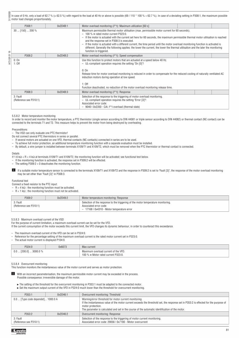
I473
GB
01 1
9
3
1100
285
81
In case of 0 Hz, only a load of 62.7 % (≈ 62.5 %) with regard to the load at 40 Hz or above is possible (69 / 110 * 100 % = 62.7 %). In case of a deviating setting in P308:1, the maximum possiblemotor load changes proportionately.
P308:1 0x2D4B:1 Motor overload monitoring (i²*t): Maximum utilization [60 s]
30 ... [150] ... 200 % Maximum permissible thermal motor utilisation (max. permissible motor current for 60 seconds). – 100 % ≡ rated motor current P323:0. – If the motor is actuated with the current set here for 60 seconds, the maximum permissible thermal motor utilisation is reached and the response set in P308:3 is executed. – If the motor is actuated with a different current, the time period until the motor overload monitoring function is activated is different. Generally the following applies: the lower the current, the lower the thermal utilisation and the later the monitoring function is triggered.
P308:2 0x2D4B:2 Motor overload monitoring (i²*t): Speed compensation
0: On Use this function to protect motors that are actuated at a speed below 40 Hz. 1: Off – UL-compliant operation requires the setting "On [0]"!
0: On Release time for motor overload monitoring is reduced in order to compensate for the reduced cooling of naturally ventilated AC induction motors during operation at low speed.
1: Off Function deactivated, no reduction of the motor overload monitoring release time.
P308:3 0x2D4B:3 Motor overload monitoring (i²*t): Response
3: Fault Selection of the response to the triggering of motor overload monitoring. (Reference see P310:1) – UL-compliant operation requires the setting "Error [3]"! Associated error code: – 9040 | 0x2350 - CiA: i²*t overload (thermal state)
5.5.8.2 Motor temperature monitoringIn order to record and monitor the motor temperature, a PTC thermistor (single sensor according to DIN 44081 or triple sensor according to DIN 44082) or thermal contact (NC contact) can beconnected to the terminals T1 and T2. This measure helps to prevent the motor from being destroyed by overheating.
Preconditions– The VSD can only evaluate one PTC thermistor! Do not connect several PTC thermistors in series or parallel.– If several motors are actuated on one VFD, thermal contacts (NC contacts) connected in series are to be used.– To achieve full motor protection, an additional temperature monitoring function with a separate evaluation must be installed.– By default, a wire jumper is installed between terminals X109/T1 and X109/T2, which must be removed when the PTC thermistor or thermal contact is connected.
DetailsIf 1.6 kΩ < R < 4 kΩ at terminals X109/T1 and X109/T2, the monitoring function will be activated; see functional test below.– If the monitoring function is activated, the response set in P309:2 will be effected.– The setting P309:2 = 0 deactivates the monitoring function.
If a suitable motor temperature sensor is connected to the terminals X109/T1 and X109/T2 and the response in P309:2 is set to "Fault [3]", the response of the motor overload monitoring may be set other than "Fault [3]" in P308:3.
Functional testConnect a fixed resistor to the PTC input:– R > 4 kΩ : the monitoring function must be activated.– R < 1 kΩ : the monitoring function must not be activated.
i
P309:2 0x2D49:2 Motor temperature monitoring: Response
3: Fault Selection of the response to the triggering of the motor temperature monitoring. (Reference see P310:1) Associated error code: – 17168 | 0x4310 - Motor temperature error
P324:0 0x6073 Max current
0.0 ... [200.0] ... 3000.0 % Maximum overload current of the VFD. 100 % ≡ Motor rated current P323:0.
P353:1 0x2D46:1 Overcurrent monitoring: Threshold
0.0 ... [Type code dependet]... 1000.0 A Warning/error threshold for motor current monitoring. If the instantaneous value of the motor current exceeds the threshold set, the response set in P353:2 is effected for the purpose of motor protection. The parameter is calculated and set in the course of the automatic identification of the motor.
P353:2 0x2D46:2 Overcurrent monitoring: Response
3: Fault Selection of the response to the triggering of motor current monitoring. (Reference see P310:1) Associated error code: 29056 | 0x7180 - Motor overcurrent
5.5.8.3 Maximum overload current of the VSDFor the purpose of current limitation, a maximum overload current can be set for the VFD.If the current consumption of the motor exceeds this current limit, the VFD changes its dynamic behaviour, in order to counteract this exceedance.
– The maximum overload current of the VFD can be set in P324:0.– Reference for the percentage setting of the maximum overload current is the rated motor current set in P323:0.– The actual motor current is displayed P104:0.
5.5.8.4 Overcurrent monitoringThis function monitors the instantaneous value of the motor current and serves as motor protection.
With an incorrect parameterisation, the maximum permissible motor current may be exceeded in the process. Possible consequence: irreversible damage of the motor.
The setting of the threshold for the overcurrent monitoring in P353:1 must be adapted to the connected motor. Set the maximum output current of the VFD in P324:0 much lower than the threshold for overcurrent monitoring.
i

I473
GB
01 1
9
3
1100
285
82
5.5.8.5 Motor phase failure detectionThe motor phase failure detection function can be activated for both synchronous and asynchronous motors.
Phase failure detection during operation is basically only suitable for applications which are operated with a constant load and speed. In all other cases, transient processes or unfavourableoperating points can cause maloperation.
If a current-carrying motor phase (U, V, W) fails during operation, the response selected in 310:1 is tripped if the following two conditions are met:– Condition 1: detection is activated. See P310:2.– Condition 2: a specific commutation angle (approx. 150° electrically) has been covered without the detection of a current flow.
5.5.8.6 Motor speed monitoringThis function monitors the motor speed during operation.
In order to detect the current motor speed, the VFD must be enabled and the motor must rotate.For an exact monitoring, rated motor speed P320:4 and rated motor frequency P320:5 must be set correctly.
If the motor speed reaches the threshold set in P350:1, the response set in P350:2 takes place.
P310:1 0x2D45:1 Motor phase failure detection: Response
0: No response Selection of the response following the detection of a motor phase failure. 1: Warning Associated error codes: 2: Trouble – 65289 | 0xFF09 - Motor phase missing 3: Fault – 65290 | 0xFF0A - Motor phase failure phase U – 65291 | 0xFF0B - Motor phase failure phase V – 65292 | 0xFF0C - Motor phase failure phase W
P310:2 0x2D45:2 Motor phase failure detection: Current threshold
1.0 ... [5.0] ... 25.0 % Current threshold for the activation of the motor phase failure detection function. – 100 % ≡ Maximum current 0x2DDF:002 – Background: in order to be able to reliably detect the failure of a motor phase, first a certain must flow for the current sensor system. The detection function is therefore only activated if the actual value of the motor current has exceeded the current threshold set here. – Display of the present motor current in P104:0.
P310:3 0x2D45:3 Motor phase failure detection: Voltage threshold
0.0 ... [10.0] ... 100.0 V Voltage threshold for the monitoring of several motor phases. – The V/f characteristic control enables the detection of several failed motor phases during operation. – Monitoring with regard to the failure of several motor phases is active if a response that is not "0: No response" is set in P310:1 and if the motor voltage exceeds the voltage threshold set here. – The monitoring function is triggered if the level of the motor current is lower than the device-dependent threshold for longer than 20 ms. – The monitoring function for the failure of several motor phases can be deactivated if the value "100.0 V" is set here.
P350:1 0x2D44:1 Overspeed monitoring: Threshold
50 ... [8000] ... 50000 rpm Warning/error threshold for motor speed monitoring. – If the motor speed reaches the threshold set, the response selected in P350:2 is effected. – The parameter is calculated and set in the course of the automatic identification of the motor.
P350:2 0x2D44:2 Overspeed monitoring: Response
3: Fault Selection of the response to the triggering of motor speed monitoring. (Reference see P310:1) Associated error code: 65286 | 0xFF06 - Motor overspeed
5.5.8.7 Motor torque monitoring
The motor torque monitoring can only be used for the following motor control types with speed controller:– Servo control (SC ASM)– Sensorless control (SL PSM)– Sensorless vector control (SLVC)
This function sets the internal status signal "Torque limit reached [79]" = TRUE if the maximum possible torque has been reached.The status signal is set irrespective of the response P329:1 and delay time P329:2 set for this monitoring.
P329:1 0x2D67:1 Maximum torque monitoring: Response
0: No response. Selection of response to reaching the maximum possible torque. For further possible settings, see P310:1. The selected response takes place if the status signal "Torque limit reached [79]" = TRUE and the deceleration time set in P329:2 has elapsed. Associated error code: 33553 | 0x8311 - Torque limit reached
P329:2 0x2D67:2 Maximum torque monitoring: Triggering delay
0.000 ... [0.000] ... 10.000 s Optional setting of a deceleration for triggering the response selected in P329:1. Typical application: – The motor should be driven at the torque limit for a short time without triggering the selected response. – Only after a longer operation (> set deceleration) at the torque limit, the selected response is to take place.
P326:0 0x6072 Max torque
0.0 ... [250.0] ... 3000.0 % Symmetrical selection of the maximum permissible torque. – 100 % ≡ Motor rated torque (P325:0) – This parameter serves to implement a statically and bipolarly acting torque limitation. This can be used, for instance, as overload protection of the mechanical transmission path/elements starting at the motor shaft. – This limitation acts irrespective of the torque limitations acting in unipolar mode that are set in 0x60E0 and x60E1.

I473
GB
01 1
9
3
1100
285
83
5.5.9 ENCODER SETTINGSIn general, an encoder is a measuring system which serves to detect the velocity/speed and possibly the position of a kinematics or motor.
The VLB3 exclusively supports HTL encoders.
5.5.9.1 HTL encoder
In case of the VLB3, the digital inputs DI3 and DI4 can be configured as HTL input to evaluate the signal of a cost-effective HTL encoder or a reference frequency ("pulse train").An HTL encoder can be used at the VLB3 for the following tasks:– As motor encoder for a motor speed feedback for speed control as precise as possible.– As setpoint encoder for defining a frequency setpoint.– As setpoint encoder for defining the reference value for the process controller.– As setpoint encoder for defining a torque setpoint.– As actual value encoder for the process controller.– As actual value encoder for the "position counter" function.
Preconditions– Single-track or two-track HTL encoder.– A single-track HTL encoder (track A) cannot be used for motor speed feedback.– A two-track HTL encoder (track A and B) must have a phase offset of exactly 90° between track A and B (error ≤ ±10°). VFD tracks are not required.– Encoder increments: ≤ 16384 increments per revolution– For supplying the encoder, the maximum supply current of the VFD must be considered.If necessary, an external 24V voltage supply for the encoder is required.
Restrictions– When the digital inputs DI3 and DI4 are configured as HTL input, these two digital inputs are no longer available for other control functions.– The HTL input can be either used for detecting an HTL encoder signal or a pulse train. They cannot be used at the same time.– The maximum input frequency of the digital inputs is 100 kHz. If this frequency is exceeded, an error is triggered.
Connections
Details
Encoder dimensioning: Calculate maximum number of increments per revolution of the encoder
Max. encoder increments = fmax [Hz] * 60s / nmax [rpm]
Max encoder increment = 100000 [Hz] * 60s / 1500 [rpm] = 4000 increments/revolution
fmax Maximum input freqeuncy of the digital inputs = 100kHz = 100000Hz
nmax Maximum encoder speed (in this example: 1500 rpm)
Max encoder increments Maximum number of increments per encoder revolution
Select an encoder with a maximum number of increments per revolution which is lower than or equal to the calculated number. The higher the number of increments per revolution, the more stable the system is.
i

I473
GB
01 1
9
3
1100
285
84
Setup:1. Set the selection "HTL encoder (AB) [1]" in P410:2 to configure the digital inputs DI3 and DI4 as encoder inputs.2. Set the encoder increment/revolution P341:1 according to the manufacturer data/encoder data sheet.3. Select the function of the encoder:P600:2 Feedback PID / P201:2 PID setpoint / P201:1 Frequency setpointNote: If SC or SLPSM mode is selected the encoder is automatically assigned as feedback.The actual encoder feedback is displayed in 0x2C42:6
P341:1 0x2C42:1 Encoder settings: Increments/revolution
1 ... [128] ... 16384 Encoder increment. Carry out setting according to manufacturer data/encoder data sheet.
P410:2 0x2630:2 Settings for digital inputs: Input function
0: Digital input Input function of the digital terminals DI3 and DI4. 1: HTL encoder (AB) 2: Pulse train 0: Digital input 3: Pulse train/direction DI3 = digital input DI4 = digital input
1: HTL encoder (AB) DI3 = HTL input for encoder track B DI4 = HTL input for encoder track A
2: Pulse train – available from version 4.1 DI3 = digital input DI4 = HTL input for pulse train
3: Pulse train/direction – available from version 4.1 DI3 = HTL input for direction specification; HIGH level = counter-clockwise (CCW) DI4 = HTL input for pulse train
- 0x2C42:6 Encoder settings: Actual velocity
Read only: x rpm Display of the speed currently detected by the encoder.
5.5.9.2 Encoder monitoringFor monitoring the HTL encoder, two monitoring functions are implemented in the VFD firmware:a) Encoder signal loss monitoring: Is triggered if a failure of the encoder signal is detected (e. g. due to open circuit or failure of the encoder current supply).b) Encoder maximum frequency monitoring: Is triggered if the calculated encoder maximum frequency is beyond the permissible frequency range of the digital inputs.
Preconditions– The encoder signal loss monitoring is only active if the HTL encoder • Is set as feedback system for the motor control or • Used as signal source for the "Position counter" function. – For the encoder signal loss monitoring ,the VSD must be enabled and the motor must rotate.– The encoder maximum frequency monitoring is active as soon as the HTL encoder has been configured.
Restrictions– The encoder signal loss monitoring does not work anymore if the "DC braking" function is active. – The response time of the encoder signal loss monitoring depends on the setting of the encoder increments/revolution in P341:1.– The settings of the speed controller can influence the encoder signal loss monitoring. If the reset time of the speed controller is very low or deactivated, an encoder signal loss cannot be
detected at switch-on.– If the HTL encoder is used as signal source for the "Position counter" function, an encoder signal loss cannot be detected at switch-on.– Combined with the "Holding brake control" function: • In order that the encoder signal loss monitoring is not triggered by mistake, monitoring will only be activated when the holding brake is released. • If Brake closing time P712:2 and Brake opening time P712:3 are not set correctly, the encoder signal loss monitoring can be triggered although an encoder signal is available.
Details on encoder signal loss monitoringThe encoder signal loss monitoring distinguishes between the following signal failures:a) Complete failure (no encoder signals available at all, e. g. in case the encoder current supply has failed)b) Only one track has failed (track A or track B)
In order to detect a complete failure, the VFD calculates internally two trigger thresholds for monitoring based on the configuration of the HTL encoder:1. Based on the encoder resolution set in P341:1, the minimum output frequency is calculated:
Note: The maximum time (tmax) per edge is 0.001 s. In order to prevent a false tripping, this value is multiplied by the factor 4.Calculation example:Number of pole pairs = 2Encoder resolution = 128 increments/revolution
2. The maximum permitted time is calculated in which a new signal edge of the encoder must arrive:
If the calculation with the (synchronous) encoder frequency at minimum output frequency (here: 2* 3.9 Hz) is carried out, the resulting time interval equals the maximum time per edge(here: 0.001s)
If the real encoder frequency is lower than the calculated minimum output frequency AND if the new signal edge has not arrived within the maximum permitted item, monitoring is triggered.The complete failure is displayed via the status bit 4 in 0x2C42:7.If only track A or B fails, signals are continued to be detected. In this case, however, the sign of the frequency changes with every new signal edge. In order to detect the failure of only one track, aninternal counter is increased by 1 every time the sign between two signal edges changes. If the sign is unchanged in two signal edges in a row, the counter is reset. If the counter reaches thecounter content "100", monitoring is triggered. The failure of only one track is displayed via the status bit 5 in 0x2C42:7.Both in case of a complete failure and in case only one track fails, the error message "Encoder open circuit" (error code 29445 | 0x7305) is output. The error response can be selected in P342:0.

I473
GB
01 1
9
3
1100
285
85
Details on encoder maximum frequency monitoringAfter the HTL encoder has been configured (or if the encoder settings are changed), the VFD internally calculates the maximum possible number of encoder pulses per second (hereinafter referredto as "encoder maximum frequency"):
If the calculated encoder maximum frequency is beyond the permissible frequency range of the digital inputs, monitoring is triggered:– The status bit 0 in 0x2C42:7 is set to "1".– The warning "Feedback system: speed limit" (error code 29573 | 0x7385) is output.
Calculation example 1:– Maximum input frequency of the digital inputs = 100 kHz– Encoder resolution P341:1 = 1024 increments/revolution– Max motor speed P322:0 = 3000 rpm
Result: The encoder maximum frequency monitoring is not triggered because the encoder maximum frequency is within the permissible frequency range of the digital inputs.
Calculation example 2:– Maximum input frequency of the digital inputs = 100 kHz– Encoder resolution P341:1 = 4096 increments/revolution– Max motor speed P322:0 = 3600 rpm
Result: the encoder maximum frequency monitoring is triggered because the encoder maximum frequency is beyond the permissible frequency range of the digital inputs.
P342:0 0x2C45 Encoder-error response
0: No response Selection of the response to the triggering of the encoder signal loss monitoring. 1: Warning Associated error code: 29445 | 0x7305 - Encoder open circuit 3: Fault
- 0x2C42:7 Encoder settings: Status
0 ... [0] ... 4294967295 Bit coded display of the status of encoder monitoring.
Bit 0 : Maximum encoder speed reached Bit 0 = “1” means that the calculated encoder maximum frequency is beyond permissible frequency Bit 4: No signal detected range of digital inputs. Bit 5: Encoder track A or B missing Bit 4 = “1” means that complete failure of the encoder signals has been detected. Bit 5 = “1” means that a failure of only one track (A or B) has been detected,
Duty selection P306:1
“Heavy Duty [0]” “Light Duty [1]”
Characteristics High dynamic requirements Low dynamic requirements
Typical applications Main tool drives, travelling drives, hoist drives, winders, Pumps, fans, general horizontal materials handling technology, forming drives and conveyors. line drives and centrifugal pumps.
Overload capacity 200% for 3s, 150% for 60s Reduced overload For details see instruction I472. For details see instruction I472.
If the VLB3 is reset to the default setting, the load characteristic is set to "Heavy Duty [0]”.
Parameters
i
5.5.10 Dual ratingThe VLB3 has two different load characteristics: "Light Duty" and "Heavy Duty". The load characteristic "Light Duty" enables a higher output current with restrictions regarding overload capacity, ambient temperature and switching frequency. As a result, the motor can be drivenby a less powerful variable speed drive. The selected load characteristic depends on the application.
NOTEThis function is available from firmware 5.1 and only for power sizes >= 4kW.
NOTELoad characteristic "Light Duty"In order to avoid irreversible damage to the VSD/motor: Based on the configuration document, check whether the VSD can be operated with the load characteristic "Light Duty". Comply with all data in the configuration document for this load characteristic and the corresponding mains voltage range. Among other things, this includes information on the type of
installation and required fuses, cable cross-sections, mains chokes and filters. Set the parameters only in accordance with the following specifications .
DetailsThe following table compares the two load characteristics:
P306:1 0x2D43:1 VSD load characteristic: Duty selection
0: Heavy Duty (heavy load) Selection of the load characteristic. 1: Light Duty (standard load) Further required settings: – Set the data of the motor used. – Set application-specific parameters such as current limits
0: Heavy Duty Load characteristic for high dynamic requirements.
1: Light Duty Load characteristic for low dynamic requirements. – The device overload monitoring (i*t) is adapted.

I473
GB
01 1
9
3
1100
285
86
5.6 GROUP 4 – I/O SETUP
5.6.1 FUNCTION LIST (RUN/STOP/START/JOG/REVERSE)Parameters P400:1…P400:49 contain the main functions of the VSD. The function can be assigned to a trigger. If the trigger is activated the function is executed. The digital trigger values cancome from external sources (Digital Inputs, Network, etc.) and internal sources (VSD status, faults, etc.) It is possible to assign more than one function to a single trigger.
Basic functionalities:– VSD enable Enables the VSD. Signal must have the state TRUE (by Input or setting) to be able to start the motor.– Run/Stop Enables the running of the motor. Can be used as single signal or in combination with the signals Start Forward / Start Reverse. Signal must have the state TRUE (by Input or setting) to be able
to start the motor.– Start Forward / Start Reverse Used to start the motor (Positive edge triggered). Stop is down with the Run/Stop signal.– Run Forward / Run Reverse Used to run and stop the motor (Maintained signals)– Rotation invertion Inverts the speed setpoint– JOG Forward / JOG Reverse JOG the motor with a fixed speed. Jog has higher priority than Run/Stop, Start or Run commands.– Fault Reset For a successful reset of a fault it is necessary to correct the condition that caused the fault first. Afterwards there are different possibilities to reset the fault:
Function to reset fault: Parameter Transition
Reset fault P400:4 FALSE > TRUE (Rising edge)
VSD enable P400:1 TRUE > FALSE (Falling Edge)
Run/Stop P400:2 TRUE > FALSE (Falling Edge)
Keypad STOP - FALSE > TRUE (Rising edge)
See chapter “5.2 Flexible I/O configuration”
In Flexible Control mode (P200:0) either VSD enable (P400:1) or Run/Stop (P400:2) must be assigned to I/O to ensure that the drive can always be stopped! (Exception: VSD is controlled from network, Network enable (P400:37) is HIGH)
NOTICE!The JOG functions have priority over Stop commands. If the VSD is currently JOGGING, pressing the STOP key on the keypad or triggering STOP command will NOT stop the motor!
P400:1 0x2631:1 VSD enable
0: Not connected State: 1: Constant TRUE TRUE enables the VSD. 11: Digital input 1 FALSE inhibits the VSD and the motor will cost stop. 12: Digital input 2 13: Digital input 3 Note: 14: Digital input 4 Signal must have the state TRUE (by Input or setting) to be able to start the motor 15: Digital input 5 50: Running 51: Ready to run 53: Stop active 54: Quick stop active 58: Device warning 59: Device fault active 60: Heatsink temp. warning 69: Rotation inverted 70: Frequency threshold exceeded 71: Actual speed = 0 78: Current threshold exceeded 79: Maximum torque 81: Error analog input 1 82: Error analog input 2 83: Loss of load 102: Sequence suspended 103: Sequence done 104: Local control active 105: Remote control active 106: Manual setpoint active 107: Automatic setpoint active
P400:2 0x2631:2 Run/Stop
11:Digital input 1 VSD Run/Stop signal (Reference see P400:1) State: TRUE will make the VSD ready to run FALSE will stop the motor according to the defined stop method
Note: Set 01 TRUE to disable the function
Signal must have the state TRUE (by Input or setting) to be able to start the motor
P400:3 0x2631:3 Quick stop
0:Not connected The quick stop function works as pause or zero speed function. If the quick stop is applied the motor will ramp down with the (Reference see P400:1) defined QSP ramp.
Note: 0: FALSE disables this functionality
i

I473
GB
01 1
9
3
1100
285
87
P400:4 0x2631:4 Reset fault
12:Digital input 2 Trigger for fault reset (Reference see P400:1) FALSE->TRUE transition the faults will be reset.
P400:5 0x2631:5 DC braking
0: Not connected Trigger = TRUE: Activate DC braking (Reference see P400:1) Trigger = FALSE: Deactivate DC braking
P400:6 0x2631:6 Start forward (CW)
0:Not connected Start forward signal (Edge triggered) (Reference see P400:1)
State: Transition FALSE-->TRUE will start the motor forward
Note: – Use P400:2 “Run/Stop” signal to stop the motor –Set the signal to 0: FALSE to disable the function – If a bipolar input (-10V..+10V) is used the direction is controlled by the reference signal
P400:7 0x2631:7 Start reverse (CCW)
0:Not connected Start reverse signal (Edge triggered) (Reference see P400:1) State: Transition FALSE-->TRUE will start the motor backward
Note: – Use P400:2 “Run/Stop” signal to stop the motor – Set the signal to 0: FALSE to disable the function – If a bipolar input (-10V..+10V) is used the direction is controlled by the reference signal
P400:8 0x2631:8 Run forward (CW)
0:Not connected Run forward signal (Maintained signal) (Reference see P400:1) State: TRUE will start the motor forward The last activated signal of run forward and run reverse defines the direction! FALSE of Run Forward and Run Reverse will stop the motor according to the defined stop method
Note: – Set the signal to 0: FALSE to disable the function – If a bipolar input (-10V..+10V) is used the direction is controlled by the reference signal
P400:9 0x2631:9 Run reverse (CCW)
0:Not connected Run reverse signal (Maintained signal) (Reference see P400:1)
State: TRUE will start the motor reverse The last activated Signal of Run Forward and Run Reverse defines the direction! FALSE of Run Forward and Run Reverse will stop the motor according to the defined stop method
Note: – Set the signal to 0: FALSE to disable the function – If a bipolar input (-10V..+10V) is used the direction is controlled by the reference signal
P400:10 0x2631:10 Jog forward (CW)
0:Not connected JOG Forward with preset frequency 5 (Reference see P400:1) State: TRUE will start the motor forward with preset frequency 5 FALSE will stop the motor If JOG forward and JOG reverse are applied at the same time the motor will stop and the JOG has to be retriggered!
WARNING: The JOG functions have priority over Stop commands. If the VSD is currently JOGGING, pressing the STOP key on the keypad or triggering STOP command will NOT stop the motor!
P400:11 0x2631:11 Jog reverse (CCW)
0:Not connected JOG Forward with preset frequency 6 (Reference see P400:1) State: TRUE will start the motor reverse with preset frequency 6 FALSE will stop the motor If JOG forward and JOG reverse are applied at the same time the motor will stop and the JOG has to be retriggered!
WARNING: The JOG functions have priority over Stop commands. If the VSD is currently JOGGING, pressing the STOP key on the keypad or triggering STOP command will NOT stop the motor!
P400:12 0x2631:12 Keypad control
0:Not connected Keypad Selection for Start/Stop command (Reference see P400:1) State: TRUE: Start and Stop commands coming from the keypad FALSE: Start and Stop commands are defined by the connection list
P400:13 0x2631:13 Invert rotation
13:Digital input 3 Rotation inversion signal (Reference see P400:1) State: TRUE: target reference setpoint is inverted (i.e. times -1) FALSE: the target reference setpoint in not inverted

I473
GB
01 1
9
3
1100
285
88
P400:14 0x2631:14 AI1 setpoint selection
0:Not connected Selects Analog input 1 as setpoint source (Reference see P400:1)
P400:15 0x2631:15 AI2 setpoint selection
0:Not connected Selects Analog input 2 as setpoint source (Reference see P400:1)
P400:16 0x2631:16 Keypad setpoint selection
0:Not connected Selects Keypad as setpoint source (Reference see P400:1)
P400:17 0x2631:17 Setpoint = Network
0: Not connected Selects Network as setpoint source. 116: Netw.Ref active Note: In Network mode (P400:37 = TRUE) the triggers P400:14 – P400:25 are not active. To select the network as setpoint source (Other Reference see P400:1) in network mode (P400:37 = TRUE) use the “Default setpoint source” (P201:1-2) or the corresponding control bits (AC Drive Control Word, C135 Control Word, NET-WordIN1).
116: TRUE if AC Drive Control Word (0x400B:1) bit 6 is active
P400:18 0x2631:18 Preset selection bit 0
14:Digital input 4 Preset frequency setpoint selection bit 0 (Reference see P400:1) Combination Example: bit0 and bit2 result in preset frequency 5
P400:19 0x2631:19 Preset selection bit 1
15:Digital input 5 Preset frequency setpoint selection bit 1 (Reference see P400:1)
P400:20 0x2631:20 Preset selection bit 2
0:Not connected Preset frequency setpoint selection bit 2 (Reference see P400:1)
P400:21 0x2631:21 Preset selection bit 3
0:Not connected Preset frequency setpoint selection bit 3 (Reference see P400:1)
Flexible I/O configuration or keypad control active Network control active P400:37 = FALSE P400:17 = FALSE P400:37 = TRUE
Prio 1: Functions for setpoint change-over Prio 1: Setpoint source selected via network control word. The priority of the functions results from the assigned triggers (in the order of the selection list): 1. Constant TRUE [1] Prio 2: Set standard setpoint source 2. Digital input 1 [11] – P201:1: Frequency control: Default setpoint source. 3. Digital input 2 [12] – P201:2: PID control: Default setpoint source. 4. Digital input 3 [13] – P201:3: Torque control. Default setpoint source. 5. ...
Prio 2: Set standard setpoint source – P201:1: Frequency control: Default setpoint source – P201:2: PID control: Default setpoint source – P201:3: Torque control: Default setpoint source
Example of allocating priority
Parameter Name Setting
P400:14 Activate AI1 setpoint Digital input 5 [15]
P400:16 Activate keypad setpoint Digital input 4 [14]
Digital input 4 Digital input 5 Active setpoint source
FALSE FALSE Standard setpoint source set in P201:1
FALSE TRUE Analog input 1
TRUE FALSE Keypad
TRUE TRUE Keypad (since "Digital input 4" trigger is higher in the selection list than "Digital input 5" trigger)
5.6.2 SETPOINT SELECTIONSince only one setpoint source can be active at a time, the following priorities apply:

I473
GB
01 1
9
3
1100
285
89
5.6.2.1 Changing the setpoint source during operation: examples
Example 1: Change-over from keypad setpoint to AI1/AI2 setpoint– The keypad is set as standard setpoint source.– The switch S1 starts the motor in the forward direction of rotation. The switch S1 in the initial position stops the motor again.– The switch S2 switches the direction of rotation.– The switch S3 activates analogue input 1 as setpoint source.– The switch S4 activates analogue input 2 as setpoint source.
If S3 and S4 are actuated at the same time, the analogue input 1 is active as setpoint source since the digital input 3 assigned to this function has a higher priority than the digital input 4.i
R1 = Frequency setpoint selection via AI1R2 = Frequency setpoint selection via AI2S1 = RunS2 = Reverse rotational directionS3 = Activate AI1 setpointS4 = Activate AI2 setpoint
Parameter Name Setting
P400:1 Enable VSD Constant TRUE [1]
P400:2 Run Digital input 1 [11]
P400:4 Reset fault Not connected [0]
P400:13 Reverse rotational direction Digital input 2 [12]
P400:14 Activate AI1 setpoint Digital input 3 [13]
P400:15 Activate AI2 setpoint Digital input 4 [14]
P400:18 Activate preset (bit 0) Not connected [0]
P200:0 Control selection Flexible I/O configuration [0]
P203:3 Stop method Standard ramp [1]
P201:1 Frequency control: Default setpoint source Keypad [1]

I473
GB
01 1
9
3
1100
285
90
The status signals can be assigned to digital outputs.① The change-over is initiated from keypad setpoint (standard setpoint source) to AI1 setpoint.② The change-over is initiated from AI1 setpoint to AI2 setpoint.③ The change-over is initiated from AI2 setpoint to AI1 setpoint since the digital input 3 has a higher priority than the digital input 4.④ The change-over is initiated to keypad setpoint (standard setpoint source).

I473
GB
01 1
9
3
1100
285
91
Example 2: Change-over from AI1 setpoint to keypad setpoint– The analog input 1 is set as standard setpoint source.– Switch S1 starts the motor in forward direction of rotation. Switch S1 in the initial position stops the motor again.– Switch S2 switches the direction of rotation.– Switch S3 activates the keypad as setpoint source. The keypad setpoint can be changed in the operating mode via the arrow navigation keys.
R1 = Frequency setpoint selectionS1 = RunS2 = Reverse rotational directionS3 = Activate keypad setpoint
Parameter Name Setting
P202:1 Keypad setpoints: Frequency setpoint 20.0 Hz
P400:1 Enable VSD Constant TRUE [1]
P400:2 Run Digital input 1 [11]
P400:4 Reset fault Not connected [0]
P400:13 Reverse rotational direction Digital input 2 [12]
P400:16 Activate keypad setpoint Digital input 3 [13]
P200:0 Control selection Flexible I/O configuration [0]
P203:3 Stop method Standard ramp [1]
P201:1 Frequency control: Default setpoint source Analog input 1 [2]
The status signals can be assigned to digital outputs. ① Change-over from analog input 1 (standard setpoint source) to keypad setpoint.② Change-over from keypad setpoint back to analog input 1 (standard setpoint source).

I473
GB
01 1
9
3
1100
285
92
Example 3: Change-over from keypad setpoint to preset 1 ... 7The four functions "Activate preset (bit 0)" ... " Activate preset (bit 3)" enable change-over of the setpoint to a parameterisable setpoint (preset value).
DetailsA preset is selected in a binary-coded fashion via the triggers assigned to the four functions "Activate preset (Bit 0)" ... " Activate preset (Bit 3)" in compliance with the following truth table:
If the frequency presets 8 ... 15 are required as well, the digital input 5 must be additionally assigned to the "Activate preset (bit 3)" function and the terminal DI5 must be interconnectedaccordingly.
i
Example for operating mode– The keypad is set as standard setpoint source.– Switch S1 starts the motor in forward direction of rotation. Switch S1 in the initial position stops the motor again.– The switches S2 ... S4 serve to switch over to the presets 1 ... 7 (see the following table).
Activate preset Selection
Bit 3 Bit 2 Bit 1 Bit 0 Preset Frequency PID setpoint Torque (P400:21) (P400:20) (P400:19) (P400:18) setpoint setpoint
FALSE FALSE FALSE FALSE No preset selected
FALSE FALSE FALSE TRUE Preset 1 P450:1 P451:1 P452:1
FALSE FALSE TRUE FALSE Preset 2 P450:2 P451:2 P452:2
FALSE FALSE TRUE TRUE Preset 3 P450:3 P451:3 P452:3
FALSE TRUE FALSE FALSE Preset 4 P450:4 P451:4 P452:4
FALSE TRUE FALSE TRUE Preset 5 P450:5 P451:5 P452:5
FALSE TRUE TRUE FALSE Preset 6 P450:6 P451:6 P452:6
FALSE TRUE TRUE TRUE Preset 7 P450:7 P451:7 P452:7
TRUE FALSE FALSE FALSE Preset 8 P450:8
TRUE FALSE FALSE TRUE Preset 9 P450:9 P451:8 P452:8
… … …
TRUE TRUE TRUE TRUE Preset 15 P450:15
Parameter Name Setting
P400:1 Enable VSD Constant TRUE [1]
P400:2 Run Digital input 1 [11]
P400:4 Reset fault Not connected [0]
P400:13 Reverse rotational direction Not connected [0]
P400:18 Activate preset (bit 0) Digital input 2 [12]
P400:19 Activate preset (bit 1) Digital input 3 [13]
P400:20 Activate preset (bit 2) Digital input 4 [14]
P200:0 Control selection Flexible I/O configuration [0]
P203:3 Stop method Standard ramp [1]
P201:1 Frequency control: Default setpoint source Keypad [1]
P450:1 Frequency setpoint presets: Preset 1 10 Hz
P450:2 Frequency setpoint presets: Preset 2 15 Hz
P450:3 Frequency setpoint presets: Preset 3 20 Hz
P450:4 Frequency setpoint presets: Preset 4 25 Hz
P450:5 Frequency setpoint presets: Preset 5 30 Hz
P450:6 Frequency setpoint presets: Preset 6 35 Hz
P450:7 Frequency setpoint presets: Preset 7 40 Hz
S1 = RunS2, S3, S4 = Preset selection:
S2 S3 S4
Off Off Off Keypad setpoint
On Off Off Preset 1
Off On Off Preset 2
On On Off Preset 3
Off Off On Preset 4
On Off On Preset 5
Off On On Preset 6
On On On Preset 7

I473
GB
01 1
9
3
1100
285
93
The status signals can be assigned to digital outputs. ① Change-over from keypad setpoint (standard setpoint source) to presets (first, preset 1 is selected).② Change-over back to keypad setpoint since no preset is selected anymore (digital inputs 2 ... 4 = FALSE).

I473
GB
01 1
9
3
1100
285
94
5.6.3 MOTOR POTENTIOMETER
With the motor potentiometer mode (MOP) the setpoint is controlled with two triggers (e.g. two digital inputs): “MOP setpoint up” (increase) and “MOP setpoint down” (decrease).
– The MOP is enabled by trigger P400:25 or can be set as default setpoint source.– Motor potentiometer up TRUE: Setpoint will increase with acceleration time 2 P222:0..– Motor potentiometer down TRUE: Setpoint will decrease with deceleration time 2 P223:0.– MOP is increasing/decreasing the setpoint according acceleration/deceleration time 2. The motor is following the setpoint with acceleration/deceleration time 1 also in MOP-mode.– If both triggers are TRUE or FALSE at the same time the setpoint will remain constant.– The start value of the MOP is defined with P413:0.
P400:23 0x2631:23 Motor potentiometer (MOP) up
0:Not connected State TRUE will increase the speed setpoint in MOP-Mode. (Reference see P400:1)
P400:24 0x2631:24 Motor potentiometer (MOP) down
0:Not connected State TRUE will decrease the speed setpoint in MOP-Mode. (Reference see P400:1)
P400:25 0x2631:25 Activate MOP setpoint
0:Not connected Trigger to enable the MOP-Mode. After enabling the speed is controlled by digital inputs MOP up / MOP down. (Reference see P400:1)
P413:0 0x4003:0 MOP Starting mode
0: Last value Defines the start setpoint value when MOP is enabled. 1: Init Value 0: Last value 2: Minimum Value MOP starts with the last MOP set value. 1: Init Value MOP starts with the value P414:1 for velocity mode, P414:2 for PID control, P414:3 for torque mode. 2: Minimum Value MOP starts with minimum frequency (P210:0) or minimum PID value (P605:1)
P414:1 0x4004:1 MOP Starting value: frequency
0.0 ... [0.0] ... 599.0 Hz Frequency start value for MOP-Mode Note: Only active if P413:0 is set to 1
P414:2 0x4004:2 MOP Starting value: PID
-300.00 ... [0.00] ... 300.00 PUnit Process controller start value for MOP-Mode Note: Only active if P413:0 is set to 1
P414:3 0x4004:3 MOP Starting value: Torque
0.0 ... [0.0] ... 1000,0% Torque start value for MOP-mode (100% = motor rated torque P325:0) Note: Only active if P413:0 is set to 1
5.6.4 USER DEFINED FAULTS
Two user defined fault can be configured. (Example: To stop motor in case of process fault) If a user defined fault occurs the VSD goes into fault state. After clearing the fault the resetting of theVSD is required.
P400:43 0x2631:43 User-defined fault 1
0:Not connected Configuration of user defined fault 1 (Reference see P400:1)
P400:44 0x2631:44 User-defined fault 2
0:Not connected Configuration of user defined fault 2 (Reference see P400:1)
5.6.5 SETPOINT SOURCE SEGMENT SETPOINTSThe four functions "Activate segment setpoint (bit 0)" ... " Activate segment setpoint´(bit 3)" enable a setpoint change-over to a segment setpoint parameterised for the "sequencer" function duringnormal operation.
See also chapter “Group 8 Sequencer”
A segment setpoint is selected in a binary-coded fashion via the triggers assigned to the four functions "Activate segment setpoint (bit 0)" ... " Activate segment setpoint´(bit 3)" in compliance withthe following truth table.
Activate segment setpoint Selection
Bit 3 Bit 2 Bit 1 Bit 0 Segment Frequency PID setpoint Torque (P400:29) (P400:28) (P400:27) (P400:26) setpoint setpoint
FALSE FALSE FALSE FALSE No segment setpoint selected
FALSE FALSE FALSE TRUE 1 P801:1 P801:6 P801:7
FALSE FALSE TRUE FALSE 2 P802:1 P802:6 P802:7
FALSE FALSE TRUE TRUE 3 P803:1 P803:6 P803:7
FALSE TRUE FALSE FALSE 4 P804:1 P804:6 P804:7
FALSE TRUE FALSE TRUE 5 P805:1 P805:6 P805:7
FALSE TRUE TRUE FALSE 6 P806:1 P806:6 P806:7
FALSE TRUE TRUE TRUE 7 P807:1 P807:6 P807:7
TRUE FALSE FALSE FALSE 8 P808:1 P808:6 P808:7
TRUE FALSE FALSE TRUE
... Invalid selection
TRUE TRUE TRUE TRUE

I473
GB
01 1
9
3
1100
285
95
P400:26 0x2631:26 Activate segment setpoint (bit 0)
0: Not connected Assignment of a trigger for the "Activate segment setpoint (bit 0)" function. (Reference see P400:1) Selection bit with the valency 20 for the bit-coded selection and activation of a parameterised segment setpoint. Trigger = FALSE: selection bit = "0". Trigger = TRUE: selection bit = "1". Notes: – During normal operation (no active sequence), this function serves to activate the setpoint of a segment (instead of an entire sequence in the sequencer operation). – This function is not intended for the use in the sequencer operation.
P400:27 0x2631:27 Activate segment setpoint (bit 1)
0: Not connected Assignment of a trigger for the "Activate segment setpoint (bit 1)" function. (Reference see P400:1) Selection bit with the valency 21 for the bit-coded selection and activation of a parameterised segment setpoint. Trigger = FALSE: selection bit = "0". Trigger = TRUE: selection bit = "1". Notes: – During normal operation (no active sequence), this function serves to activate the setpoint of a segment (instead of an entire sequence in the sequencer operation). – This function is not intended for the use in the sequencer operation.
P400:28 0x2631:28 Activate segment setpoint (bit 2)
0: Not connected Assignment of a trigger for the "Activate segment setpoint (bit 2)" function. (Reference see P400:1) Selection bit with the valency 22 for the bit coded selection and activation of a parameterised segment setpoint. Trigger = FALSE: selection bit = "0". Trigger = TRUE: selection bit = "1". Notes: – During normal operation (no active sequence), this function serves to activate the setpoint of a segment (instead of an entire sequence in the sequencer operation). – This function is not intended for the use in the sequencer operation
P400:29 0x2631:29 Activate segment setpoint (bit 3)
0: Not connected Assignment of a trigger for the "Activate segment setpoint´(bit 3)" function. (Reference see P400:1) Selection bit with the valency 23 for the bit coded selection and activation of a parameterised segment setpoint. Trigger = FALSE: selection bit = "0". Trigger = TRUE: selection bit = "1". Notes: – During normal operation (no active sequence), this function serves to activate the setpoint of a segment (instead of an entire sequence in the sequencer operation). – This function is not intended for the use in the sequencer operation.
5.6.6 HTL INPUT SETPOINT SOURCEThe digital inputs DI3 and DI4 can be configured as HTL input to evaluate the signal of a cost-effective HTL encoder or a reference frequency ("pulse train").Many cost-effective control systems have a pulse-train output as an alternative to a real analog output.– The HTL input can be defined as standard setpoint source. – The "Activate setpoint via HTL input” P400:22 function enables a setpoint change-over to the HTL input.
Preconditions– A setpoint change-over to the HTL input is only effected if no setpoint source with a higher priority has been selected. – For using the digital inputs DI3 and DI4 as HTL input, the corresponding input function must be set in P410:2.
See also chapter “5.5.8 Encoder settings”
Restrictions– When the digital inputs DI3 and DI4 are configured as HTL input, these two digital inputs are no longer available for other control functions.– The HTL input can be either used for detecting an HTL encoder signal or a pulse train. They cannot be used at the same time.– The maximum input frequency of the digital inputs is 100 kHz. If this frequency is exceeded, an error is triggered.
DetailsFor detecting a pulse train, the following two configurations are supported:a) input function P410:2 = "Pulse train [2]" (DI4 = input for pulse train, DI3 = normal digital input)
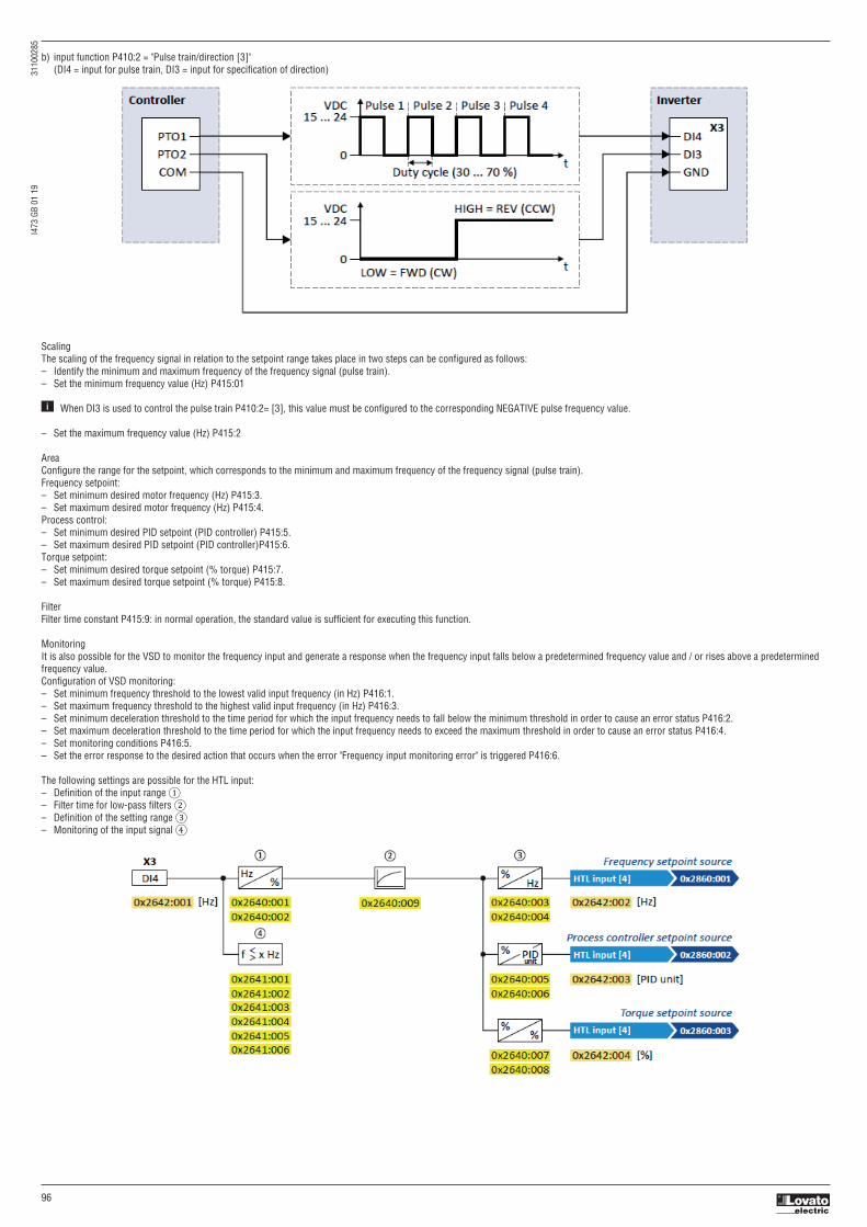
I473
GB
01 1
9
3
1100
285
96
b) input function P410:2 = "Pulse train/direction [3]" (DI4 = input for pulse train, DI3 = input for specification of direction)
ScalingThe scaling of the frequency signal in relation to the setpoint range takes place in two steps can be configured as follows:– Identify the minimum and maximum frequency of the frequency signal (pulse train).– Set the minimum frequency value (Hz) P415:01
When DI3 is used to control the pulse train P410:2= [3], this value must be configured to the corresponding NEGATIVE pulse frequency value.
– Set the maximum frequency value (Hz) P415:2
AreaConfigure the range for the setpoint, which corresponds to the minimum and maximum frequency of the frequency signal (pulse train).Frequency setpoint:– Set minimum desired motor frequency (Hz) P415:3.– Set maximum desired motor frequency (Hz) P415:4.Process control:– Set minimum desired PID setpoint (PID controller) P415:5.– Set maximum desired PID setpoint (PID controller)P415:6.Torque setpoint:– Set minimum desired torque setpoint (% torque) P415:7.– Set maximum desired torque setpoint (% torque) P415:8.
FilterFilter time constant P415:9: in normal operation, the standard value is sufficient for executing this function.
MonitoringIt is also possible for the VSD to monitor the frequency input and generate a response when the frequency input falls below a predetermined frequency value and / or rises above a predeterminedfrequency value.Configuration of VSD monitoring:– Set minimum frequency threshold to the lowest valid input frequency (in Hz) P416:1.– Set maximum frequency threshold to the highest valid input frequency (in Hz) P416:3.– Set minimum deceleration threshold to the time period for which the input frequency needs to fall below the minimum threshold in order to cause an error status P416:2.– Set maximum deceleration threshold to the time period for which the input frequency needs to exceed the maximum threshold in order to cause an error status P416:4.– Set monitoring conditions P416:5.– Set the error response to the desired action that occurs when the error "Frequency input monitoring error" is triggered P416:6.
The following settings are possible for the HTL input:– Definition of the input range ①– Filter time for low-pass filters ②– Definition of the setting range ③– Monitoring of the input signal ④
i

I473
GB
01 1
9
3
1100
285
97
For detecting an HTL encoder AB signal, the input function "HTL encoder (AB) [1]" must be set in P410:2 instead. More details for configuring the HTL encoder can be found in chapter "Encoder settings".
P400:22 0x2631:22 Activate setpoint via HTL input
0: Not connected Assignment of a trigger for the "Activate setpoint via HTL input" function. (Reference see P400:1) Trigger = TRUE: HTL input is used as setpoint source (if the trigger assigned has the highest setpoint priority). Trigger = FALSE: no action / deactivate function again.
P415:1 0x2640:1 HTL input settings: Minimum frequency
-100000.0 ... [0.0] ... 100000.0 Hz Definition of the input range of the HTL input.
P415:2 0x2640:2 HTL input settings: Maximum frequency
-100000.0 ... [0.0] ... 100000.0 Hz Definition of the input range of the HTL input.
P415:3 0x2640:3 HTL input settings: Minimum motor frequency
-1000.0 ... [0.0] ... 1000.0 Hz Definition of the setting range for operating mode "MS: Velocity mode". – Direction of rotation according to sign. – The standard setpoint source for operating mode P301:0 = "MS: Velocity mode [-2]" is selected in P201:1.
P415:4 0x2640:4 HTL input settings: Maximum motor frequency
1000.0 ... [50.0] ... 1000.0 Hz Definition of the setting range for operating mode "MS: Velocity mode". – Direction of rotation according to sign. – The standard setpoint source for operating mode P301:0 = "MS: Velocity mode [-2]" is selected in P201:1.
P415:5 0x2640:5 HTL input settings: Minimum PID setpoint
-300.00 ... [0.00] ... 300.00 PID unit Definition of the setting range for PID control. – The standard setpoint source for the reference value of PID control is selected in P201:2.
P415:6 0x2640:6 HTL input settings: Maximum PID setpoint
-300.00 ... [100.00] ... 300.00 PID unit Definition of the setting range for PID control. – The standard setpoint source for the reference value of PID control is selected in P201:2.
P415:7 0x2640:7 HTL input settings: Minimum torque setpoint
-400.0 ... [0.0] ... 400.0 % Definition of the setting range for operating mode "MS: Torque mode". – 100 % ≡ Motor rated torque P325:0. – Direction of rotation according to sign. – The standard setpoint source for operating mode P301:0 = "MS: Torque mode [-1]" is selected in P201:3.
P415:8 0x2640:8 HTL input settings: Minimum torque setpoint
-400.0 ... [100.0] ... 400. Definition of the setting range for operating mode "MS: Torque mode". – 100 % ≡ Motor rated torque P325:0. – Direction of rotation according to sign. – The standard setpoint source for operating mode P301:0 = "MS: Torque mode [-1]" is selected in P201:3.
P415:9 0x2640:9 HTL input settings: Filter time constant
0 ... [10] ... 10000 ms PT1 time constant for low-pass filter.
P416:1 0x2641:1 HTL input monitoring: Minimum frequency threshold
-214748364.8 ... [0.0] ... 214748364.7 Hz Settings for monitoring the HTL input.
P416:2 0x2641:2 HTL input monitoring: Minimum delay threshold
0.0 ... [5.0] ... 300.0 s Settings for monitoring the HTL input.
P416:3 0x2641:3 HTL input monitoring: Maximum frequency threshold
-214748364.8 ... [0.0] ... 214748364.7 Hz Settings for monitoring the HTL input.
P416:4 0x2641:4 HTL input monitoring: Maximum delay threshold
0.0 ... [5.0] ... 300.0 s Settings for monitoring the HTL input.
P416:5 0x2641:5 HTL input monitoring: Monitoring conditions
1: Below minimum frequency 1: Below minimum frequency 2: Above maximum frequency Input frequency < minimum frequency threshold P416:1 longer than the deceleration P416:2. 3: Below min. or above max. frequency 2: Above maximum frequency Input frequency > maximum frequency threshold P416:3 longer than the deceleration P416:4.
3: Below min. or above max. frequency Input frequency < minimum frequency threshold P416:1 longer than the deceleration P416:2 OR input frequency > maximum frequency threshold P416:3 longer than the deceleration P416:4.
P416:6 0x2641:6 HTL input monitoring: Error response
1: Warning Selection of the response to the triggering of the HTL input monitoring. (Reference see P310:1) • Associated error code: 28803 | 0x7083 - HTL input fault
Intended useThe HTL input can be used for the following tasks:– As a standard setpoint source
Intended use Parameter Setting
As a setpoint source for specifying a frequency setpoint. P201:1 HTL input [4]
As setpoint source for defining the reference value for P201:2 HTL input [4] the process controller.
As a setpoint source for specifying a torque setpoint. P201:3 HTL input [4]
As an alternative to the setting as a standard setpoint source, the "Activate setpoint via HTL input” P400:22 function can be used to enable a setpoint change-over to the HTL input.
– As an actual value source or feedforward source for the following functions:
Intended use Parameter Setting
As an actual value source for the process controller. P600:2 HTL input [6]
As a speed feedforward source for the process controller. P600:4 HTL input [9]

I473
GB
01 1
9
3
1100
285
98
P410:2 0x2630:2 Settings for digital inputs: Input function
0: Digital input Input function of the digital terminals DI3 and DI4. 1: HTL encoder (AB) 2: Pulse train 0: Digital input 3: Pulse train/direction DI3 = digital input DI4 = digital input
1: HTL encoder (AB) DI3 = HTL input for encoder track B DI4 = HTL input for encoder track A
2: Pulse train – available from version 4.1 DI3 = digital input DI4 = HTL input for pulse train
3: Pulse train/direction – available from version 4.1 DI3 = HTL input for direction specification; HIGH level = counter-clockwise (CCW) DI4 = HTL input for pulse train
Diagnostic parameters:– The input frequency is displayed in P115:1 (read only x.x Hz).– The scaled frequency value is displayed in P115:2 (read only x.x Hz).– The scaled process controller value is displayed in P115:3 (read only x.xx PID unit).– The scaled torque value is displayed in P115:4 (read only x.x%).
Configuration example.Example 1: Input range 10 ... 85 kHz ≡ setting range 0 ... 50 HzIn this configuration, a frequency setpoint between 0 and 50 Hz can be set with an HTL input frequency between 10 and 85 kHz.
Example 2: Pulse train as frequency setpoint sourceThis example shows a configuration to control the frequency setpoint of the VSD via pulse train:– Switch S1 starts the motor. Switch S1 in the initial position stops the motor again.– Scaling of the pulse train signal: Input range 10 ... 85 kHz ≡ setting range -50 ... 50 Hz.– HTL input monitoring is configured in such a way that a warning is output if the pulse train signal falls below the minimum input frequency of 10 kHz for longer than 2 s.
Parameter Name Setting
P415:1 HTL input settings: Minimum frequency 10000.0 Hz
P415:2 HTL input settings: Maximum frequency 85000.0 Hz
P415:3 HTL input settings: Minimum motor frequency 0.0 Hz
P415:4 HTL input settings: Maximum motor frequency 50.0 Hz
P415:9 HTL input settings: Filter time constant 10 ms
Switch S1: Run
PTO1: Pulse train output of the Controller
PTO2: Specification of direction of rotation of the Controller

I473
GB
01 1
9
3
1100
285
99
Parameter Name Setting
P400:1 Enable VSD Constant TRUE [1]
P400:2 Run Digital input 1 [11]
P410:2 Settings for digital inputs: Input function Pulse train/direction [3]
P210:1 Frequency control: Default setpoint source HTL input [4]
HTL input settings
P415:1 HTL input settings: Minimum frequency 10000.0 Hz
P415:2 HTL input settings: Maximum frequency 85000.0 Hz
P415:3 HTL input settings: Minimum motor frequency 0.0 Hz
P415:4 HTL input settings: Maximum motor frequency 50.0 Hz
P415:9 HTL input settings: Filter time constant 10 ms
HTL input monitoring
P416:1 Minimum frequency threshold 10000.0 Hz
P416:2 Minimum delay threshold 2.0 s
P416:5 Monitoring conditions Below minimum frequency [1]
P416:6 Error response Warning [1]
① If the VSD is enabled and no error is active, the motor can be started with the "Run" function. The motor follows the pulse train according to the set input and setting range.② The "counter-clockwise (CCW)" direction of rotation is requested externally (Controller; PTO2) via digital input DI3.③ If the pulse train signal falls below the input frequency of 10 kHz, for longer than 2 s, a warning is output.④ If "Run" is set to FALSE, the motor is stopped with the stop method set in P203:3. In the example: Stop with standard ramp.
5.6.7 ACTIVATING DC BRAKING MANUALLYBy means of the "Activate DC braking" function, DC braking can be activated manually
P400:5 0x2631:5 Activate DC braking
0: Not connected Trigger = TRUE: Activate DC braking. (Reference see P400:1) Trigger = FALSE: Deactivate DC braking. CAUTION! DC braking remains active as long as the trigger is set to TRUE.
P704:1 0x2B84:1 DC braking: Current
0.0 ... [0.0] ... 200.0 % Braking current for DC braking. 100 % ≡ rated motor current (P323:0)
For more information see chapter “DC BRAKE SETUP”

I473
GB
01 1
9
3
1100
285
100
5.6.8 RELEASING HOLDING BRAKE MANUALLYThe "Release holding brake" function serves to release the holding brake immediately. Brake application time and brake opening time as well as the conditions for the automatic operation are noteffective.
Preconditions– Observe setting and application notes in the chapter “5.9.8 Holding brake control” – The brake mode "Automatic [0]" or "Manual [1]" must be set in P712:1.– The "Release holding brake [115]" trigger has to be assigned to a digital output or, in the simplest case, to the relay which then switches the brake supply.
Details
Detailed information about the function and configuration of the holding brake control can be found in the chapter "5.9.8 Holding brake control".
5.6.9 FUNCTIONS FOR PARAMETER CHANGE-OVERThe VSD supports several parameter sets. The parameter set can be selected by means of the "Select parameter set (bit 0)" and "Select parameter set (bit 1)" functions.
DANGER!Changed parameter settings can become effective immediately depending on the activating method set in P755:0.The possible consequence is an unexpected response of the motor shaft while the VSD is enabled. If possible, only carry out parameter changes while the VSD is disabled. Certain device commands or settings which might cause a critical state of the drive behavior can generally only be carried our when the VSD is inhibited.
DetailsThe "parameter change-over" function provides a change-over between four sets with different parameter values for up to 32 freely selectable parameters. For details on the compilation of theparameters and setting of the value sets, see the chapter "5.9.1.5 Parameter change-over".A value set is selected in a binary-coded fashion via the triggers assigned to the two Select parameter set (bit 0)" and " Select parameter set (bit 1)" functions in compliance with the following truthtable:
P400:49 0x2631:49 Release holding brake
0: Not connected Assignment of a trigger for the "Release holding brake" function. (Reference see P400:1) Trigger = TRUE: Release holding brake (immediately). Trigger = FALSE: no action. Notes: – Function is only executed if the brake mode P712:1 is set to "Automatic [0]" or "Manual [1]". CAUTION! – The manually triggered "Release holding brake" command has a direct impact on the "Release holding brake [115]" trigger. Thus, the holding brake can be manually released if the power section is switched off! – The responsibility for a manual release of the holding brake has the external trigger source for the "Release holding brake" command!
Select parameter set Select parameter set Selection (bit 1) (bit 0) P400:42 P400:41
FALSE FALSE Value set 1
FALSE TRUE Value set 2
TRUE FALSE Value set 3
TRUE TRUE Value set 4

I473
GB
01 1
9
3
1100
285
101
Change-over is effected depending on the activation method selected in P755:0 when a state change of the selection inputs takes place or via the trigger assigned to the "Load parameter set"function.
P400:40 0x2631:40 Load parameter set
0: Not connected Assignment of a trigger for the "Load parameter set" function. (Reference see P400:1) Trigger = FALSE-TRUE edge: parameter change-over to the value set selected via "Select parameter set (bit 0)" and "Select parameter set (bit 1)". Trigger = FALSE: no action. Notes: – The activation method for the "Parameter change-over" function can be selected in P755:0.
P400:41 0x2631:41 Select parameter set (bit 0)
0: Not connected Assignment of a trigger for the "Select parameter set (bit 0)" function. (Reference see P400:1) Selection bit with the valency 20 for "Parameter change-over" function. Trigger = FALSE: selection bit = "0". Trigger = TRUE: selection bit = "1".
P400:42 0x2631:42 Select parameter set (bit 1)
0: Not connected Assignment of a trigger for the "Select parameter set (bit 1)" function. (Reference see P400:1) Selection bit with the valency 21 for "Parameter change-over" function. Trigger = FALSE: selection bit = "0". Trigger = TRUE: selection bit = "1".
P755:0 0x4046 Activation of parameter set
0: Via command (disable required) Selection of the activation method for the parameter change-over. 1: Via command (immediately) – If the selection is changed from "Via command... [0]/[1]" to "If the selection is changed...[2]/[3]" after switch-on, the parameter 2: If the selection is changed (disable required) set selected via the functions "Select parameter set (bit 0)" and "Select parameter set (bit 1)" is activated immediately. 3: If the selection is changed (immediately) In case of selection [2], however, this only takes place if the VSD is disabled, the motor is stopped or an error is active.
0: Via command (disable required) The parameter set selected via the functions "Select parameter set (bit 0)" and "Select parameter set (bit 1)" is activated if the trigger assigned to the "Load parameter set" function in P400:40 provides a FALSE-TRUE edge AND the VSD is inhibited, the motor is stopped or an error is active.
1: Via command (immediately) The parameter set selected via the functions "Select parameter set (bit 0)" and "Select parameter set (bit 1)" is immediately activated if the trigger assigned to the "Load parameter set" function in P400:40 provides a FALSE-TRUE edge.
2: If the selection is changed (disable required) The parameter set selected via the functions "Select parameter set (bit 0)" and "Select parameter set (bit 1)" is activated if the state of these selection bits changes AND the VSD is inhibited, the motor is stopped or an error is active.
3: If the selection is changed (immediately) The parameter set selected via the functions "Select parameter set (bit 0)" and "Select parameter set (bit 1)" is activated immediately if the state of these selection bits is changed.

I473
GB
01 1
9
3
1100
285
102
5.6.10 UPS OPERATIONThis function enables the operation of a three-phase 400V variable speed drive with an uninterruptible single phase 230V power supply (UPS) to be able to operate the motor with reduced load fora certain period in the event of a power failure.
NOTES– This function is available from firmware version 5.1– UPS operation is not suitable for a continuous operation. Possible consequence: Device overload Prevent a too frequent use of this function.
Restrictions– UPS operation is only available for VLB3 up to 11 kW.– For UPS operation, one reduced output current and one reduced overload are available only: • Output current: 60 % of the 400V rated current • Overload: 80 %/5 min, 120 %/3 s of the 400V rated current– In order to change over to UPS operation, a minimum delay of 10 s is required.
DetailsThe following figure shows the principal connection of the UPS to the VLB3. For further technical details, please contact the VSD manufacturer.
① A mutual locking is required for the contactors Q1 and Q2.② In this example, the digital input DI5 is used to activate the UPS operation. For this purpose, the function "Activate UPS operation" P400:55 must be assigned to trigger "Digital input 5 [15]".③ In order to change over to UPS operation, a minimum delay of 10 s is required.
The UPS operation can be alternatively activated via network. In this case, a bit of the mappable data word NetWordIN1 P590:1 must be assigned to the "Activate UPS operation [55]" function.
If the UPS operation is active,– The device overload monitoring (i*t) is adapted accordingly.– The DC limit values are reduced.– The phase failure detection is switched off.– The warning "UPS operation active" (error code 12672 | 0x3180) is output.– Trigger "UPS operation active [118]" is set to TRUE. The trigger can be assigned to a digital output.– Bit 15 ("UPS operation active") in the drive status word 2 0x2833 is set to "1".
Notes:– An additional limitation of speed, current, etc. can be realised via the application with the "Parameter change-over“ function.

I473
GB
01 1
9
3
1100
285
103
P400:55 0x2631:055 Activate UPS operation
0: Not connected Assignment of a trigger to the "Activate UPS operation" function. (Reference: see P400:1) Trigger = TRUE: Activate UPS operation. Trigger = FALSE: no action / deactivate function again.
HIGH active (default setting) LOW active
– Internally, the digital input terminals are set to LOW level via pulldown resistors. – Internally, the digital input terminals are set to HIGH level via pull-up resistors. – The current flows from the current supply (e.g. X3/24V) through the contact to the digital – The current flows from the digital input terminal through the contact to GND. input terminal (and internally via the pull-down resistor to GND). – If the contact is closed, the digital input is set to LOW level and is thus LOW active. – If the contact is closed, the digital input is set to HIGH level and is thus HIGH active.
Connection plan (example): Connection plan (example):
Parameter
Parameter
Parameter Designation Setting for this example
P400:1 VSD enable Constant TRUE [1]
P400:2 Run Digital input 1 [11]
P400:55 Activate UPS operation Digital input 5 [15]
The status signals can be assigned to digital outputs.
① In order to change over to UPS operation, a minimum delay is required.
5.6.11 DIGITAL INPUT CONFIGURATIONThe digital inputs are used for control operations. The following configurations are available for the digital inputs signals.
Assertion level "HIGH active" or "LOW active"The digital inputs can be configured in P410:1 HIGH active (default setting) or LOW active:
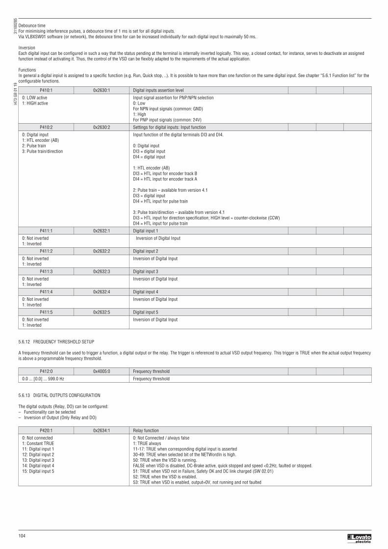
I473
GB
01 1
9
3
1100
285
104
Debounce timeFor minimising interference pulses, a debounce time of 1 ms is set for all digital inputs.Via VLBXSW01 software (or network), the debounce time for can be increased individually for each digital input to maximally 50 ms.
InversionEach digital input can be configured in such a way that the status pending at the terminal is internally inverted logically. This way, a closed contact, for instance, serves to deactivate an assignedfunction instead of activating it. Thus, the control of the VSD can be flexibly adapted to the requirements of the actual application.
FunctionsIn general a digital inpiut is assigned to a specific function (e.g. Run, Quick stop, ..). It is possible to have more than one function on the same digital input. See chapter “5.6.1 Function list” for theconfigurable functions.
P410:1 0x2630:1 Digital inputs assertion level
0: LOW active Input signal assertion for PNP/NPN selection 1: HIGH active 0: Low For NPN input signals (common: GND) 1: High For PNP input signals (common: 24V)
P410:2 0x2630:2 Settings for digital inputs: Input function
0: Digital input Input function of the digital terminals DI3 and DI4. 1: HTL encoder (AB) 2: Pulse train 0: Digital input 3: Pulse train/direction DI3 = digital input DI4 = digital input
1: HTL encoder (AB) DI3 = HTL input for encoder track B DI4 = HTL input for encoder track A
2: Pulse train – available from version 4.1 DI3 = digital input DI4 = HTL input for pulse train
3: Pulse train/direction – available from version 4.1 DI3 = HTL input for direction specification; HIGH level = counter-clockwise (CCW) DI4 = HTL input for pulse train
P411:1 0x2632:1 Digital input 1
0: Not inverted Inversion of Digital Input 1: Inverted
P411:2 0x2632:2 Digital input 2
0: Not inverted Inversion of Digital Input 1: Inverted
P411:3 0x2632:3 Digital input 3
0: Not inverted Inversion of Digital Input 1: Inverted
P411:4 0x2632:4 Digital input 4
0: Not inverted Inversion of Digital Input 1: Inverted
P411:5 0x2632:5 Digital input 5
0: Not inverted Inversion of Digital Input 1: Inverted
5.6.12 FREQUENCY THRESHOLD SETUP
A frequency threshold can be used to trigger a function, a digital output or the relay. The trigger is referenced to actual VSD output frequency. This trigger is TRUE when the actual output frequencyis above a programmable frequency threshold.
P412:0 0x4005:0 Frequency threshold
0.0 ... [0.0] ... 599.0 Hz Frequency threshold
5.6.13 DIGITAL OUTPUTS CONFIGURATION
The digital outputs (Relay, DO) can be configured:– Functionality can be selected– Inversion of Output (Only Relay and DO)
P420:1 0x2634:1 Relay function
0: Not connected 0: Not Connected / always false 1: Constant TRUE 1: TRUE always 11: Digital input 1 11-17: TRUE when corresponding digital input is asserted 12: Digital input 2 30-49: TRUE when selected bit of the NETWordIn is high. 13: Digital input 3 50: TRUE when the VSD is running. 14: Digital input 4 FALSE when VSD is disabled, DC-Brake active, quick stopped and speed <0,2Hz, faulted or stopped. 15: Digital input 5 51: TRUE when VSD not in Failure, Safety OK and DC link charged (SW 02.01) 52: TRUE when the VSD is enabled. 53: TRUE when VSD is enabled, output=0V, not running and not faulted

I473
GB
01 1
9
3
1100
285
105
30: Netword IN1 - bit 12 54: TRUE when quick stop is selected and active. 31: Netword IN1 - bit 13 55: TRUE if the integrated safety system has inhibited the VSD. 32: Netword IN1 - bit 14 56: TRUE when the VSD has a fault condition. 33: Netword IN1 - bit 15 57: TRUE when the VSD has a fault condition that is locked and cannot be reset. 34: NETWordIN2 - bit 0 58: TRUE when a warning is present. 35: NETWordIN2 - bit 1 59: TRUE when a trouble condition is present. 36: NETWordIN2 - bit 2 60: TRUE when the heat sink temperature exceeds the warning level 37: NETWordIN2 - bit 3 65: TRUE when a PTC fault is detected. 38: NETWordIN2 - bit 4 66: TRUE when a flying start or a restart is active 39: NETWordIN2 - bit 5 67: TRUE when the DC brake is on. 40: NETWordIN2 - bit 6 69: TRUE when output frequency is negative 41: NETWordIN2 - bit 7 70: TRUE when the output frequency is > the frequency threshold (P412:0) 42: NETWordIN2 - bit 8 71: TRUE when the output frequency is zero +/- 0.01Hz 43: NETWordIN2 - bit 9 72: TRUE when the VSD reaches the commanded setpoint and setpoint <> 0 Hz 44: NETWordIN2 - bit 10 73: TRUE when the PID feedback is equal to the programmed setpoint +/- 2% 45: NETWordIN2 - bit 11 74: TRUE when in Sleep mode 46: NETWordIN2 - bit 12 75: TRUE when a minimum alarm is triggered (reference to P608:1) 47: NETWordIN2 - bit 13 76: TRUE when a maximum alarm is triggered (reference to P608:2) 48: NETWordIN2 - bit 14 77: TRUE when no minimum/maximum alarm is active. (reference to P608:1 & P608:2) 49: NETWordIN2 - bit 15 78: TRUE when the actual motor current has exceeded the level in P324:0. 50: Running 79: TRUE when the actual torque has exceeded the level in P326:0, 0x60E0:0 or 0x60E1:0. 51: Ready for operation 81: TRUE when loss of the analog input 1 has been detected. P430:8-10 52: VSD enable 82: TRUE when loss of the analog input 2 has been detected. P431:8-10 53: Stop active 83: TRUE when no load is detected 54: Quick stop active 100: TRUE when the control is executed via the sequencer. 55: VSD disabled (safety) 101: TRUE if the sequence is running and is currently not suspended. 56: Fault active 102: TRUE if the sequence is currently suspended. 57: Fault interlocking 103: TRUE if the sequence is completed. 58: Device warning 104: TRUE when local (LOC) mode is active (local keypad control) 59: Trouble active 105: TRUE when remote (REM) mode is active (all control sources EXCEPT keypad control) 60: Heatsink temp. warn. active 106: TRUE when manual (MAN) mode is active (Keypad setpoint control) 65: PTC fault 107: TRUE when automatic (AUTO) mode is active (All setpoint sources other than Keypad) 66: Flying restart 108: TRUE when parameter set #1 is loaded and active. 67: DC brake active 109: TRUE when parameter set #2 is loaded and active. 69: Inverse rotation 110: TRUE when parameter set #3 is loaded and active. 70: Frequency thld exceeded 111: TRUE when parameter set #4 is loaded and active. 71: Actual speed = 0 112: TRUE after any parameter set 1…4 change-over has completed without error. 72: Setpoint speed reached 113: TRUE when any parameter set load fails. 73: PID feedback = setpoint 115: TRUE when brake release signal is TRUE (either by auto trigger or manual trigger). 74: PID idle state active 117: TRUE if a motor phase failure has been detected. 75: PID min alarm active 118: TRUE if UPS operation is active. 76: PID max alarm active 155: TRUE if the integrated safety system has triggered the “Safe Torque Off” (STO) function and if the safe inputs 77: PID min-max alarm active SIA and SIB = LOW (simultaneously). 78: At current limit 79: At torque limit 81: Error analog input 1 82: Error analog input 2 83: Loss of load 100: Sequencer controlled 101: Sequence active 102: Sequence suspended 103: Sequence done 104: Local control active 105: Remote control active 106: Manual setpoint active 107: Automatic setpoint active 108: Parameter set 1 active 109: Parameter set 2 active 110: Parameter set 3 active 111: Parameter set 4 active 112: Parmeter set load OK 113: Parameter set load fail 115: Holding brake release 117: Motor phase failure 118: UPS operation active 155: STO active
P420:2 0x2634:2 Digital output 1 function
115:Holding brake release Function of Digital Output 1 (Reference see P420:1) (Reference list see P420:1)
P421:1 0x2635:1 Inversion of relay output
0: Not inverted Inversion of Relay Output 1: Inverted
P421:2 0x2635:2 Inversion of digital output 1
0: Not inverted Inversion of Digital Output 1 1: Inverted

I473
GB
01 1
9
3
1100
285
106
5.6.14 ANALOG INPUT SETTINGS
The VSD is equipped with two analog inputs. These can be configured as reference or feedback singal.The following settings are available:– Input configuration– Input filter time / Input Dead time– Input monitoring function– Input scaling
** Availability of scaling depending on type of VSD.
P430:1 0x2636:1 AI 1 configuration
0: 0...10VDC Configuration of input range of Analog input 1. 1: 0...5VDC 2: 2...10VDC 3: -10...+10VDC 4: 4...20mA 5: 0...20mA
P430:2 0x2636:2 Analog input 1: Min frequency value [Hz]
-1000.0 ... [0.0] ... 1000.0 Hz Frequency scaling of the analog input Represents the minimum of the analog input value
P430:3 0x2636:3 Analog input 1: Max frequency value [Hz]
-1000.0 ... [50.0] ... 1000.0 Hz Frequency scaling of the analog input Represents the maximum of the analog input value
P430:4 0x2636:4 Analog input 1: Min PID value [Punit/%]
-300.00 ... [0.00] ... 300.00 PUnit/% PID scaling of the analog input Represents the minimum of the analog input value
P430:5 0x2636:5 Analog input 1: Max PID value [Punit/%]
-300.00 ... [100.00] ... 300.00 PUnit/% PID scaling of the analog input Represents the maximum of the analog input value
P430:6 0x2636:6 Analog input 1: Filter time
0 ... [10] ... 10000 ms Analog input filter time constant
P430:7 0x2636:7 Analog input 1: Deadband
0.0 ... [0.0] ... 100.0 % Configuration of the deadband such that any input value below this percentage will be treated as 0Hz. (In % of Max Input Value) Example: Deadband 10% of 50Hz: -10V … 10V Deadband -5Hz … 5 Hz 0 … 10V Deadband 0Hz … 5 Hz
P430:8 0x2636:8 Analog input 1: Monitoring threshold
-100.0 ... [0.0] ... 100.0 % Monitoring threshold of the analog input (example: 100% = 10V if AI1 is configured as 0-10V voltage input).
P430:9 0x2636:9 Analog input 1: Monitoring condition
0: Below trigger threshold Monitoring condition of the analog input 1. If the selected condition is met, the “Error of analog input 1 active [81]” trigger is set 1: Above trigger threshold to true.
P430:10 0x2636:10 Analog input 1: Error response
3:Fault The selected response takes place if the monitoring condition selected in P430:9 is met for at least 500ms. (Reference see P310:1)
P430:11 0x2636:11 Analog input 1: Min torque value
-400.0 ... [0.0] ... 400.0 % Definition of the setting range for operating mode “MS: Torque mode”. 100% = max permissible torque (P326:0). Direction of rotation according to sign. The standard setpoint source for operating mode P301:0 = “MS: Torque mode [1]” is selected in P201:3
P430:12 0x2636:12 Analog input 1: Max torque value
-400.0 ... [100.0] ... 400.0 % See P430:11

I473
GB
01 1
9
3
1100
285
107
P431:1 0x2637:1 AI2 configuration
0: 0...10VDC Configuration of input range of Analog input 2. 1: 0...5VDC 2: 2...10VDC 3: -10...+10VDC 4: 4...20mA 5: 0...20mA (*)
P431:2 0x2637:2 Analog input 2: Min value [Hz]
-1000.0 ... [0.0] ... 1000.0 Hz Frequency scaling of the analog input Represents the minimum of the analog input value
P431:3 0x2637:3 Analog input 2: Max value [Hz]
-1000.0 ... [50.0] ... 1000.0 Hz Frequency scaling of the analog input Represents the maximum of the analog input value
P431:4 0x2637:4 Analog input 2: Min value [Punit/%]
-300.00 ... [0.00] ... 300.00 PUnit/% PID/Torque scaling of the analog input Represents the minimum of the analog input value
P431:5 0x2637:5 Analog input 2: Max value [Punit/%]
-300.00 ... [100.00] ... 300.00 PUnit/% PID/Torque scaling of the analog input Represents the maximum of the analog input value
P431:6 0x2637:6 Analog input 2: Filter time
0 ... [10] ... 10000 ms Analog input filter time constant
P431:7 0x2637:7 Analog input 2: Deadband
0.0 ... [0.0] ... 100.0 % Configuration of the deadband such that any input value below this percentage will be treated as 0Hz. (In % of Max Input Value) Example: Deadband 10% of 50Hz: -10V … 10V Deadband -5Hz … 5 Hz 0 … 10V Deadband 0Hz … 5 Hz
P431:8 0x2637:8 Analog input 2: Monitoring level threshold
-100.0 ... [0.0] ... 100.0 % Monitoring threshold of the analog input
P431:9 0x2637:9 Analog input 2: Monitoring condition
0: Below trigger threshold Monitoring condition of the analog input 2. If the selected condition is met, the “Error of analog input 2 active [82]” trigger 1: Above trigger threshold is set to TRUE.
P431:10 0x2637:10 Analog input 2: Error response
3:Fault The selected response takes place if the monitoring condition selected in P431:9 is met for at least 500ms. (Reference see P310:1)
P431:11 0x2637:11 Analog input 2: Min torque value
-400.0 ... [0.0] ... 400.0 % Definition of the setting range for operating mode “MS: Torque mode”. 100% = max permissible torque (P326:0). Direction of rotation according to sign. The standard setpoint source for operating mode P301:0 = “MS: Torque mode [1]” is selected in P201:3
P431:12 0x2637:12 Analog input 2: Max torque value
-400.0 ... [100.0] ... 400.0 % See P431:11
5.6.15 ANALOG OUTPUT SETTINGS
The analog output can be used to send a feedback signal to the control system (I. e. Motor current, Actual Frequency, …). Different functions and output configurations are available.

I473
GB
01 1
9
3
1100
285
108
P440:1 0x2639:1 AO1 configuration
0: Disabled Configuration of Analog output signal 1 1: 0...10VDC 2: 0...5VDC 3: 2...10VDC 4: 4...20mA 5: 0...20mA
P440:2 0x2639:2 AO1 function
0: Not active Analog output function1 1: Output frequency 2: Frequency setpoint Scaling factors: 3: Analog input 1 1: [0.1 Hz] 4: Analog input 2 2: [0.1 Hz] 5: Motor current 3: [0.1 %] 6: Output power 4: [0.1 %] 7: Torque actual value 5: [0.1 A] 10: Sequencer controlled 6: [0.001 kW] 20: NETWordIN3 7: [0.1 %] 21: NETWordIN4 10: [0.01 V] 20: [0.1 %] 21: [0.1 %]
P440:3 0x2639:3 AO1 minimum signal
-- ... [0] ... -- Minimum scaling of the analog output 1 Setting x Scaling factor = Minimum analog output value:
Example: Setting 10, 'Actual output frequency' Minimum analog output value = 10 x 0.1 Hz = 1Hz
P440:4 0x2639:4 AO1 maximum signal
-- ... [1000] ... -- Maximum scaling of the analog Output 1 Setting x Scaling factor = Maximum analog output value:
Example: Setting 500, 'Actual output frequency' Maximum analog output value = 500 x 0.1 Hz = 50Hz

I473
GB
01 1
9
3
1100
285
109
5.6.16 PRESET SETPOINTS (FREQUENCY, PID, TORQUE)
The VSD has 15 preset frequency setpoints, 8 preset PID setpoints, 8 preset torque setpoints. They can be selected in two ways:– As default setpoint (Frequency: P201:1, PID: P201:2, Torque: P201:3)– Triggered by digital inputs (P400:18 – 400:21) The Preset setpoint selection is done by a binary combination of bits triggering the Preset Setpoint Selection Functions. Combination Example: bit0 and bit2 result in Preset 6
See chapter “5.6.2 Setpoint selection”
P450:1 0x2911:1 Frequency preset 1
0.0 ... [20.0] ... 599.0 Hz Frequency setpoint 1
P450:2 0x2911:2 Frequency preset 2
0.0 ... [40.0] ... 599.0 Hz Preset frequency setpoint 2
P450:3 0x2911:3 Frequency preset 3
0.0 ... [Type code dependent] ... 599.0 Hz Preset frequency setpoint 3
P450:4 0x2911:4 Frequency preset 4
0.0 ... [0.0] ... 599.0 Hz Preset frequency setpoint 4
P450:5 0x2911:5 Frequency preset 5
0.0 ... [0.0] ... 599.0 Hz Preset frequency setpoint 5 Note: Also used for Jog FWD
P450:6 0x2911:6 Frequency preset 6
0.0 ... [0.0] ... 599.0 Hz Preset frequency setpoint 6 Note: Also used for Jog REV
P450:7 0x2911:7 Frequency preset 7
0.0 ... [0.0] ... 599.0 Hz Preset frequency setpoint 7
P450:8 0x2911:8 Frequency preset 8
0.0 ... [0.0] ... 599.0 Hz Preset frequency setpoint 8
P450:9 0x2911:9 Frequency preset 9
0.0 ... [0.0] ... 599.0 Hz Preset frequency setpoint 9
P450:10 0x2911:10 Frequency preset 10
0.0 ... [0.0] ... 599.0 Hz Preset frequency setpoint 10
P450:11 0x2911:11 Frequency preset 11
0.0 ... [0.0] ... 599.0 Hz Preset frequency setpoint 11
P450:12 0x2911:12 Frequency preset 12
0.0 ... [0.0] ... 599.0 Hz Preset frequency setpoint 12
P450:13 0x2911:13 Frequency preset 13
0.0 ... [0.0] ... 599.0 Hz Preset frequency setpoint 13
P450:14 0x2911:14 Frequency preset 14
0.0 ... [0.0] ... 599.0 Hz Preset frequency setpoint 14
P450:15 0x2911:15 Frequency preset 15
0.0 ... [0.0] ... 599.0 Hz Preset frequency setpoint 15
P451:1-8 0x4022:1-8 Process controller preset 1-8
-300.00 ... [0.00] ... 300.00 PUnit Preset PID setpoint 1-8
P452:1-8 0x2912:1-8 Torque preset 1-8
-400.00 ... [100.0] ... 400.0 % Preset torque setpoint 1-8 – 100% = motor rated torque (P325:0) – Available from version 4.1.

I473
GB
01 1
9
3
1100
285
110
The digital inputs can be used to activate functions of the process controller. The specific assignment of the digital inputs and type of the contacts (switches or buttons, normally-closed contacts ornormally-open contacts) depends on the application.
Basic process controller settingsThe process controller is set in two steps:1. Basic settings2. Fine adjustment of the PID controller for an optimum control mode
Basic settingsBased on the default setting, we recommend the following proceeding:– Activate PID control: Set the desired operating mode (normal or reverse operation) in P600:1.– If the feedback of the variable is to take place via analog input 2 instead of analog input 1: Set P600:2 = "analog input 2 [2]".– Configure used analog input: • Configure input range. • Configure setting range for the PID control. • Adapt filter time to minimise impacts of the noise on the variable. • Set monitoring response to "No response [0]".– If a (temporary) change-over to a speed-controlled operation is to be possible via a digital input: • Assign a free digital input to the control function "Deactivate PID controller" in P400:45. As long as the digital input provides a TRUE signal, the PID control is ignored and the motor is driven
in a speed-controlled way. • Set acceleration time P606:1 and deceleration time P606:2 for speed-controlled drive control.– Select the standard setpoint source for the reference value in P201:2. • Functions for setpoint change-over can be used as well. • The keypad setpoint can be preset in P202:2. • If process controller presets are used, they have to be set in P451:1 ...P451:8. • If the analog input is used as setpoint source, it must be configured accordingly. • If the motor potentiometer is used as setpoint source, this function must be configured accordingly. – Set the speed range to be controlled in P600:3.– If the output value of the process controller is to be limited, adapt the following parameters: • P600:5: Min speed limit • P600:6: Max speed limit– Try out the following parameters with the default setting and only adapt them if required: • P604:0: Setpoint ramp • P607:1: Acceleration time for showing the process controller influence • P607:2: Deceleration for hiding the process controller influence– Diagnostics: Check current reference value and feedback of the variable: • The current reference value (setpoint) is displayed in P121:1. • The current variable (actual value) is displayed in P121:2.After the basic setting of the process controller has been carried out, a fine adjustment of the PID controller must be executed for an optimum control mode (see the following section).
Fine adjustment of the PID controllerThe dynamics of the PID controller is parameterised based on the gain of the P component P601:0, the reset time for the I component P602:0 and the gain of the D component P603:0. In thedefault setting, the process controller operates as PI controller, the D component is deactivated.
5.7 GROUP 5 – FIELDBUS
For information regarding the fieldbus parameters refer to the communication manual of VLB3 instruction I488, downlodable from the website www.LovatoElectric.com.
5.8 GROUP 6 – PID SETUPBy means of the process controller, a process variable can be regulated, for instance the pressure of a pump. The process controller is also referred to as "PID controller" (PID controller =proportional, integral and differential controller).The process controller is part of a closed control loop. The variable to be influenced (controlled variable) is measured continuously by means of a sensor and supplied to the VSD as an analogsignal (actual value) which, in the VSD, is then compared to the reference value (setpoint). The system deviation resulting therefrom is supplied to the process controller which, on this basis, decelerates or accelerates the motor speed according to the desired dynamic performance of thecontrol loop, so that, for instance, a pump always generates the desired pressure.
Connection plan (example)The following sample connection plan shows the control of a pump ①. The feedback of the variable (here: pressure) takes place via a pressure transducer ② connected to the analog input 1.

I473
GB
01 1
9
3
1100
285
111
Basics • If only the P component is used and the system operates in a steady-state status (reference value is constant and process variable is controlled to a fixed value), a certain system deviation
always continues to exist. This remaining system deviation is also called "stationary deviation". • The I component ensures that no permanent system deviation remains. Here, the reset time P602:0 determines how much the duration of the control deviation influences the control. A high
reset time means a lower influence of the I component and vice versa. • The D component does not respond to the height of the system deviation but to their rate of change only. The D component acts as a "damper" for overshoots. Overshoots may occur if the
control tries to respond quickly to changes in the system deviation or the reference value. Thus, the D component reduces the risk of instabilities due to overshoots.
For most applications, the setting of the gain of the P component and the reset time for the I component is sufficient for the fine adjustment. The setting of the gain of the D component may by required for a further stabilisation of the system especially if a quick response to system deviations is to take place.
Execute fine adjustment:1. Set the reset time for the I component to 6000 ms in P602:0 to deactivate the I component. • With this setting and the default setting of P603:0, the process controller operates as P controller.2. Increase gain of the P component step by step in P601:0 unit the system gets instable.3. Reduce gain again until the system is stable again.4. Reduce gain by another 15 %.5. Set reset time for the I component P602:0. • With this setting it should be noted that a too low reset time may cause overshoots, especially in case of high steps of the system deviation.6. Set optional gain of D component in P603:0. • With this setting it should be noted that the D component responds very sensitively to electrical disturbance on the feedback as well as digitisation errors.
i
5.8.1 PID SETUP
P600:1 0x4020:1 Operating mode
0: Disabled PID Operating mode 1: Normal operation 2: Reverse operation 0: Disabled: 3: Normal bi-drectional PID is disabled 4: Reverse bi-directional 1: Normal operation Direct acting system. Motor needs to increase the speed to increase the feedback signal. Example: Booster pump regulated by Pressure. (Increase of Motor speed results in an increase of the pressure) Motor can turn only in one direction
2: Reverse operation Motor needs to increase the speed to decrease the feedback signal. Example: Cooling water pump regulated by temperature. (Increase of the cooling pump speed results in a decrease of the temperature.) Motor can run only in one direction
3: Normal bi-directional Normal acting mode. Motor can run in both directions.
4: Reverse bi-directional Reverse acting mode. Motor can run in both directions.
P600:2 0x4020:2 Feedback source
1: Analog input 1 Selection of the PID feedback source 2: Analog input 2 Note: The PID set point and PID Feedback can be different signals! 3: DC Bus voltage 4: Motor Current 5: Network 6: HTL input
P600:3 0x4020:3 Controlled speed range
0 ... [100] ... 100 % Defines the % of the VSD output frequency that PID will regulate to. Example: P211:0 Max frequency = 50 Hz P600:3 PID Controlled sped range = 80 % --> Max calculated PID setpoint 40 Hz
P600:4 0x4020:4 Speed feedforward source
0: No Speed Added Selection of Speed feedforward source 1: Keypad frequency setpoint PID speed output = Speed feedforward source + PID controlled speed 2: Analog input 1 (Used for Trim control, Dancer control). The line speed (feed-forward) value is added to the calculated PID output frequency value 3: Analog input 2 (see PID block diagram above). 4: Preset frequency setpoint 1 5: Preset frequency setpoint 2 6: Preset frequency setpoint 3 7: Preset frequency setpoint 4 8: Network
P601:0 0x4048:0 P component gain
0.0 ... [5.0] ... 1000.0 % PID controller P gain % of max Frequency that results from a 1% PID Error Example: PID Error = 20 PUnits P601:0 P component gain = 2% P211:0 Maximum frequency = 50Hz --> PID Output = PID Error * P Gain * (Maximum frequency / 100) --> PID Output = 10 Hz
P602:0 0x4049:0 I component reset time
20 ... [400] ... 6000 ms PID controller adjustment time Tn - Value "6000 ms" deactivates the I component. - With P400:47 the I Part can be disabled

I473
GB
01 1
9
3
1100
285
112
P603:0 0x404A:0 D component gain
0.0 ... [0.0] ... 20.0 s PID controller D gain % of max Frequency that results from of 1%/s change of the PID Error
P604:0 0x404B:0 Setpoint ramp (PID)
0.0 ... [20.0] ... 100.0 s PID Setpoint ramp up/down time (Time from Analog Min to Analog Max)
5.8.2 PID FUNCTION SELECTION
P400:45 0x2631:45 Deactivate PID control
0:Not connected Switch off PID controller by external trigger (Reference see P400:1) Trigger=TRUE: if PID control is activated, ignore PID control and drive the motor in speed-controlled manner. Trigger=FALSE: if PID control is activated, drive the motor with PID control. Note. The PID control mode can be selected in P600:1.
P400:46 0x2631:46 PID output forced to 0
0:Not connected Switch off PID controller output to zero (Reference see P400:1) State: TRUE: The output of the PID controller is forced to 0. FALSE: No action
P400:47 0x2631:47 PID integrator disabled
0:Not connected Disable PID I-componed (integrator) by external Trigger (Reference see P400:1)
5.8.3 PID SPEED LIMITS
P600:5 0x4020:5 PID minimum speed limit
-100.0 ... [-100.0] ... 100.0 % – 100% = maximum frequency (P211:0) – The limitation becomes effective after the line speed has been added – The value set here also limits the I component of the PID (Integrator-Anti-Windup)
P600:6 0x4020:6 PID maximum speed limit
-100.0 ... [100.0] ... 100.0 % Maximum output value of the process controller – 100% = maximum frequency (P211:0) – The limitation becomes effective after the line speed has been added. – The value set here also limits the I component of the PID (Integrator-Anti-Windup)
5.8.4 PID SETPOINT LIMITS
P605:1 0x404E:1 Minimum setpoint
-300.00 ... [-300.00] ... 300.00 PUnit Minimum limitation of the PID setpoint
P605:2 0x404E:2 Maximum setpoint
-300.00 ... [300.00] ... 300.00 PUnit Maximum limitation of the PID setpoint
5.8.5 PID ACCELERATION / DECELERATION
P606:1 0x4021:1 Acceleration time
0.0 ... [1.0] ... 3600.0 s PID output Acceleration time (Time from 0 to Maximum frequency)
P606:2 0x4021:2 Deceleration time
0.0 ... [1.0] ... 3600.0 s PID output Deceleration time (Time from Maximum frequency)

I473
GB
01 1
9
3
1100
285
113
5.8.6 PID INFLUENCE
The Influence of the PID can be ramped up / down with a external Trigger.Example usage: winding application.
P400:48 0x2631:48 Activate PID influence ramp
1:Constant TRUE Assignment of a trigger for the "Activate PID influence ramp" function. (Reference see P400:1) Trigger = TRUE: the influence of the process controller is shown via a ramp. Trigger = FALSE or not connected: the influence of the process controller is hidden via ramp. Notes: – The influence of the process controller is always active (not only when PID control is activated). – Acceleration time for showing the influence of the process controller can be set in P607:1. – Deceleration time for hiding the influence of the process controller can be set in P607:2.
P607:1 0x404C:1 Ramp up time
0.0 ... [5.0] ... 999.9 s Ramp up time during switch ON of influencing (P400:48 PID influence ramps active) (Time from 0 to Maximum frequency)
P607:2 0x404C:2 Ramp Down Time
0.0 ... [5.0] ... 999.9 s Ramp down time during switch OFF of influencing (P400:48 PID influence ramps active) (Time from Maximum frequency to 0)
5.8.7 PID ALARMS
P608:1 0x404D:1 MIN alarm threshold
-300.00 ... [0.00] ... 300.00 PUnit Minimum alarm of PID feedback signal If PID feedback signal is lower than Min alarm level the signal is activated. Signal can be used to switch Digital Output / Relays / Network Output (Selection 75-77)
P608:2 0x404D:2 MAX alarm threshold
-300.00 ... [100.00] ... 300.00 PUnit Maximum alarm of PID feedback signal If PID feedback signal is high than Min alarm level the signal is activated. Signal can be used to switch Digital Output / Relays / Network Output (Selection 75-77)
P608:3 0x404D:3 Monitoring bandwidth PID feedback signal
0.00 ... [2.00] ... 100.00 % Hysteresis for status signal “PID feedback = setpoint [73]” (from V4.1) – 100% = configurated variable input range – Example: variable input range 0...10V → 2% = 0,2V – The status signal “PID feedback = setpoint [73] is TRUE if the controlled variable feedback = process controller setpoint (±hysteresis set here)
5.8.8 PID IDLE (SLEEP) AND RINSE FUNCTION
The PID has an integrated sleep & rinse function.– Sleep function: Stop PID if there is no demand from the process– Rinse function: Start the VSD periodically during sleep mode to prevent accumulation of deposits in the piping or the pump system.
Process controller idle stateIf the PID control is activated, this function sets the drive in process controller mode to an energy-saving idle state when no power is required.
A typical application for this function is a booster pump for water in a high-rise building. If no tenant opens the water tap or uses the shower for a longer period of time, the pump changes to theenergy-saving idle state. This usually happens at night. The idle state automatically ends as soon as a tenant opens the tap again. The pumps operates normally again until the condition for the idlestate is pending again.The conditions for activating and terminating the idle state can be set independently of one another:– P610:1 : Condition for activating the idle state.– P610:6: Condition for terminating the idle state.
P610:1 0x4023:1 PID sleep mode: Activation
0: Disabled Selection of the condition for activating the idle state. 1: Setpoint < threshold 2: Setpoint < threshold OR process variable > 0: Disabled feedback threshold Idle state deactivated. 3: Setpoint < threshold OR process variable < feedback threshold 1: Setpoint < threshold Activation of idle state if frequency setpoint P102:0 < frequency threshold P610:3 longer than the deceleration time P610:5.
2: Setpoint < threshold OR process variable > feedback threshold Activation of idle state if – Frequency setpoint P102:0 < frequency threshold P610:3 longer than the deceleration time P610:5 OR – Feedback variable P121:2 > feedback threshold P610:4 longer than the deceleration time P610:5.
3: Setpoint < threshold OR process variable < feedback threshold Activation of idle state if – Frequency setpoint P102:0 < frequency threshold P610:3 longer than the deceleration time P610:5 OR – Feedback variable P121:2 < feedback threshold P610:4 longer than the deceleration time P610:5.

I473
GB
01 1
9
3
1100
285
114
P610:2 0x4023:2 PID sleep mode: Stop method
0: Coasting Selection of the stop method after activation of the idle state. 1: Deceleration to standstill 2: Stop method set 0: Coasting The motor becomes torqueless (coasts down to standstill).
1: Deceleration to standstill The motor is brought to a standstill with deceleration time 1 (or deceleration time 2, if activated). – Deceleration time 1 can be set in P221:0. – Deceleration time 2 can be set in P223:0.
2: Stop method set The stop method set in P203:3 is used.
P610:3 0x4023:3 PID sleep mode: Frequency threshold
0.0 ... [0.0] ... 599.0 Hz Frequency threshold for the activation of the idle state. For comparing "output frequency < frequency threshold P610:3” in case of selection 1 ... 3 in P610:1.
P610:4 0x4023:4 PID sleep mode: Feedback threshold
-300.00 ... [0.00] ... 300.00 PID unit Feedback threshold for the activation of the idle state. – For comparing "fedback variable > feedback threshold P610:4 in case of selection 2 in P610:1. – For comparing "fedback variable < feedback threshold P610:4 in case of selection 3 in P610:1.
P610:5 0x4023:5 PID sleep mode: Delay time
0.0 ... [0.0] ... 300.0 s Minimum time for which the respective threshold must be underrun or exceeded before the idle state is activated.
P610:6 0x4023:6 PID sleep mode: Recovery
0: Setpoint > threshold OR system deviation >bandwidth Selection of the condition for terminating the idle state. 1: Process variable < recovery threshold 2: Process variable > recovery threshold 0: Setpoint > threshold OR system deviation >bandwidth Completion of idle state if – frequency setpoint P102:0 > (frequency threshold P610:3 + 2 Hz hysteresis) OR – in case of active PID control system deviation > bandwidth P610:7 and bandwidth P610:7 ≠ 0.
1: Process variable < recovery threshold Completion of idle state if the controlled variable fedback P121:2 < completion threshold P610:8.
2: Process variable > recovery threshold Completion of idle state if the controlled variable fedback P121:2 > completion threshold P610:8.
P610:7 0x4023:7 PID sleep mode: Bandwidth
0.00 ... [0.00] ... 300.00 PID unit Range around the process controller setpoint for terminating the idle state. 0.00 = Bandwidth deactivated.
P610:8 0x4023:8 PID sleep mode: Recovery threshold
-300.00 ... [0.00] ... 300.00 PID unit Termination threshold for idle state.
Process controller rinse functionThis function accelerates the motor in idle state of the process controller at regular intervals to a defined speed.
A typical application for this function is the rinsing of a pipe system with a pump that has been in an inactive state for a longer period to prevent deposits.– In order to activate the rinsing function, set the selection "Enabled [1]" in P615:1.– The following diagram demonstrates the function:
P615:1 0x4024:1 Automatic rinsing: Rinsing in idle state
0: Inhibited 1 = activate automatic rinsing in idle state. 1: Enabled
P615:2 0x4024:2 Automatic rinsing: Rinse interval
0.0 ... [30.0] ... 6000.0 min Time interval between two rinsing processes.
P615:3 0x4024:3 Automatic rinsing: Rinse speed
-599.0 ... [0.0] ... 599.0 Hz Speed setpoint for rinse function.
P615:4 0x4024:4 Automatic rinsing: Rinse period
0.0 ... [0.0] ... 6000.0 s Duration of a rinsing process.

I473
GB
01 1
9
3
1100
285
115
5.9 GROUP 7 – AUXILIARY FUNCTIONS
5.9.1 RESET PARAMETERS TO DEFAULTWith the "Load default settings" device command, all parameters can be reset to the default setting.
By executing this device command, all parameter settings made by the user are lost!
Details– All current parameters in the RAM memory of the VLB3 are overwritten by the default parameters stored in the firmware of the drive. (The persistent parameters in the memory module remain
unaffected by this measure.)
i
Afterwards the VLB3 can be parameterised again on the basis of this initial state.– Typical application: incorrect or unknown parameter settings.– The device command only has an effect on the RAM. For a permanent acceptance of the changes made, the data must subsequently be saved in the memory module. → See chapter
“Saving/loading the parameter settings”.
5.9.2 SAVING/LOADING THE PARAMETER SETTINGSIf parameter settings of the VSD are changed, these changes at first are only made in the RAM memory of the VSD. In order to save the parameter settings with mains failure protection, the VSD isprovided with a pluggable memory module and corresponding device commands.
DetailsThe memory module is provided with two memories, the user memory and the OEM memory.
User memoryThe user memory is used as power-failure-proof storage of parameter settings made by the user during commissioning/operation.– The SET display blinks on the keypad if a parameter setting has been changed but has not been saved in the memory module with mains failure protection. In order to save parameter settings in
the user memory of the memory module, press and hold the keypad "Enter" key for longer than 3 s.
– Parameter settings carried out with VLBXSW01 software or via network must be explicitly saved in the user memory by means of the "Save user data" device command, so that the changescarried out are not lost when the mains of the VSD are switched.
– Saving can also be made in the VLBXSW01 software via the button or the <F6> function key.– The device command "Load user data" serves to reload the data from the user memory into the RAM.
P700:1 0x2022:1 Device commands: Load default settings
0: Off / ready 1 ≡ reset all parameters in the RAM memory of the VSD to the default setting that is stored in the VSD firmware. 1: On / start – All parameter changes made by the user are lost during this process! 2: In progress – It may take some seconds to execute the task. When the task has been executed successfully, the value 0 is shown. 3: Action cancelled – Loading parameters has a direct effect on the cyclic communication: The data exchange for control is interrupted and a 4: No access communicationerror is generated. 5: No access (VSD disabled) – Setting can only be changed if the VSD is inhibited.

I473
GB
01 1
9
3
1100
285
116
OEM memoryThe OEM memory is provided for the storage of customised parameter settings by the OEM/ mechanical engineer. If the user carries out parameter settings with the keypad, they are always savedin the user memory if the keypad Enter key is pressed longer than 3 s. The OEM memory remains unaffected by these changes.– With the "Load OEM data" device command, the parameter settings preconfigured by the OEM/mechanical engineer can be reloaded to the RAM memory of the VSD at any time if required.– For saving parameter settings in the OEM memory, the "Save OEM data" device command must be executed explicitly. The parameter settings are simultaneously saved in the user memory.
Response after initial switch-on of the VSDAfter switch-on, the VSD first tries to load the parameter settings stored in the user memory.If the user memory is empty or damaged, an error message is output and the user must intervene:– Case 1 = user memory empty: → default setting is loaded automatically from the firmware → data are saved automatically in the user memory of the memory module.– Case 2 = user memory damaged: → Error message → default setting is loaded automatically → data are saved automatically in the user memory of the memory module.– Case 3 = OEM memory empty/damaged: → error message → data are loaded automatically from the user memory of the memory module.
P700:3 0x2022:3 Save user data
0: Off / ready 1 = save current parameter settings in the user memory of the memory module with mains failure protection. 1: On / start – It may take some seconds to execute the task. When the device command has been executed successfully, the value 0 is shown. 2: In progress – Do not switch off the supply voltage during the saving process and do not unplug the memory module from the VSD! 3: Action cancelled – When the VSD is switched on, all parameters are automatically loaded from the user memory of the memory module to the 4: No access RAM memory of the VSD. 5: No access (VSD disabled)
P700:4 0x2022:4 Load user data
0: Off / ready 1 = load data from the main memory of the memory module to the RAM memory of the VSD. 1: On / start – When the device command has been executed successfully, the value 0 is shown. 2: In progress – Loading parameters has a direct effect on the cyclic communication: The data exchange for control is interrupted and a 3: Action cancelled communication error is generated. 4: No access 5: No access (VSD disabled)
P700:5 0x2022:5 Load OEM data
0: Off / ready 1 = load data from the OEM memory of the memory module to the RAM memory of the VSD. 1: On / start – When the device command has been executed successfully, the value 0 is shown. 2: In progress – Loading parameters has a direct effect on the cyclic communication: The data exchange for control is interrupted and a 3: Action cancelled communication error is generated. 4: No access 5: No access (VSD disabled)
P700:6 0x2022:6 Save OEM data
0: Off / ready 1 = save current parameter settings in the OEM memory of the memory module with mains failure protection. 1: On / start – At the same time, the parameter settings are saved in the main memory of the memory module. 2: In progress – When the device command has been executed successfully, the value 0 is shown. 3: Action cancelled 4: No access 5: No access (VSD disabled)
Parameter
5.9.3 KEYPAD SETUP
P701:0 0x2862:0 Keypad setpoints
1 ... [1] ... 100 Defines the setpoint increment by pressing UP/DOWN buttons on the keypad. Preset increments: Frequency = 0.1 Hz, PID = 0.01 Punit, Torque = 1%
P702:0 0x4002:0 Speed display scaling
0.00 ... [0.00] ... 650.00 User unit can be shown on the keypad during running of hte motor. (Example: Calculated speed after gearbox) The scaling factor P702:0 defines the user unit: User unit = "Actual frequency" x P702:0 The scaled user unit is also shown in P101:0 (0x400D:0) Note: 0: Function disabled In PID mode the user unit has to be selected setting P703:0 to the scaled user unit (Set P703:0 = 0x400D0000)
P703:0 0x2864:0 Keypad display
0x0 ... [0x0] ... 0xFFFFFF00 The parameter which is show on the keypad during running of the motor can be configured. Format: 0xiiiiss00 (iiii = Index heximal, ss=subindex) Note: 0: Function disabled Only parameters from group 1 can be selected.
P705:0 0x2863:0 Keypad language selection
0: No Language 1: English 2: German Selects the language of the Keypad

I473
GB
01 1
9
3
1100
285
117
P708:1 0x2602:1 Keypad setup: CTRL & F/R key setup
0: CTRL & F/R Disable Disable/enable CTRL and F/R key of the keypad. 1: CTRL & F/R Enable Available from version 4.1 2: CTRL Enable F/R Disable 3: CTRL Disable F/R Enable
P708:2 0x2602:2 Keypad setup: Keypad rotation setup
0: Forward Instructed direction of rotation if local keypad control is active. 1: Reverse – If the local keypad control is active, this setting can be directly changed via the keypad key R-F if the key in P708:1 has not been disabled. – When the remote control is changed over to local keypad control and vice versa, this parameter is set to "Forward [0]". Available from version 4.1
P708:3 0x2602:3 Keypad setup: Keypad Full Control
0: Off Activate/deactivate full keypad control. 1: On – This setting can be changed directly via the keypad key CTRL if the key in P708:1 has not been disabled. – When the control mode is changed over, the motor is stopped and the "Forward" direction of rotation is set. Available from version 4.1
5.9.4 DELETE LOGBOOK
P700:15 0x2022:15 Device commands: Delete logbook
0: Off / ready 1 = delete all entries in the logbook. 1: On / start Setting can only be changed if the VSD is inhibited.
LED “Power” /green) LED “TX/RX” (yellow) LED “WLAN” (green) Status/meaning
off off off No supply voltage
Self-test (duration approx. 1 s)
on on on
off off Ready for operation - no active WLAN connection
Communication active
Flashing on
off Client mode - waiting for connection
blinking
off off Trouble
blinking
5.9.5 WIRELESS LAN (WLAN)The pluggable Wi-Fi module VLBXC03 enables:– an easy access to VSDs that are installed in difficult access areas,– an easy parameter setting without cable and instead of the keypad,– a comfortable monitoring and adaptation of the machine.The VSD can be accessed via WLAN with the VLBXSW01 software.VLBXC03 is compatible with VSD with firmware version >= 4.1.
5.9.5.1 WLAN LED status displaysInformation on the Wi-Fi module VLBXC03 status can be obtained quickly via the LED displays "Power", "TX/RX" and "WLAN" on the front of the Wi-Fi module.The meaning can be seen from the table below.
After being plugged in, the Wi-Fi module needs approx. 20 seconds until it is ready for operation.
5.9.5.2 WLAN basic settingsThe WLAN functionality can be configured via the following parameters.
– The WLAN module can be connected and removed during operation.– The WLAN module can either create an own WLAN network (access point mode, default setting) or implement itself as a WLAN client in an already existing WLAN network. For details see the
following subchapters.– The WLAN connection is encrypted. The WLAN encryption can be selected in 0x2441:9.– 0x2441:12 can be used to set that the name of the WLAN network, called SSID, is not visible for other WLAN devices. As a result, the number of WLAN networks displayed on PC can be
reduced.– Two data sources are possible for the WLAN settings: VSD and WLAN module. • Data source - VSD: The WLAN settings saved in the VSD are used. Each VSD has its own WLAN settings. • Data source - WLAN module: The WLAN settings saved in the WLAN module are used. In this "stand-alone" mode, the WLAN module can be plugged onto another VSD and then be used with the same settings (irrespective of the WLAN settings of the VSD).– The data source is activated with 0x2440.– The currently active data source is displayed in 0x2442:4.
i

I473
GB
01 1
9
3
1100
285
118
- 0x2440 Initiate WLAN
0: No action / no error Restart WLAN network with default setting or current settings. 1: Restart with current values 2: Restart with default values 0: No action / no error 11: Restart with current values Only status display.
1: Restart with current values Restart WLAN network with current settings of the WLAN parameters. The WLAN settings of the active data source (VSD or WLAN module) are used. – The active data source is displayed in 0x2442:4. – The data source is not changed by this selection.
2: Restart with default values Restart WLAN network with default setting of the WLAN parameters. – The WLAN settings saved in the WLAN module are deleted. – Active data source for the WLAN settings is now the VSD.
11: Restart with current values Restart WLAN network with current settings of the WLAN parameters. – The current settings are saved in the WLAN module. – Active data source for the WLAN settings is now the WLAN module.
- 0x2441:4 WLAN settings: DHCP
0: Disabled 1 = Dynamic Host Configuration Protocol (DHCP) is enabled. 1: Enabled – In the access point mode, the DHCP server of the WLAN module is activated. – In the client mode, the DHCP-client function is activated.
- 0x2441:5 WLAN settings: DHCP start address
0 ... [0] ... 4294967295 Definition of the start address when the Dynamic Host Configuration Protocol (DHCP) is used. – Only relevant for access point mode. – When 0 is set, the active IP address + 1 is used as start address.
- 0x2441:6 WLAN settings: WLAN operation mode
0: Access point mode Definition of the operating mode of the WLAN module. 1: Client mode 0: Access point mode For a direct connection to another WLAN device, the WLAN module creates an own WLAN network.
1: Client mode The WLAN module can be integrated as WLAN client into an already existing WLAN network.
- 0x2441:7 WLAN settings: WLAN SSID
Name (Service Set Identifier, SSID) of the WLAN network.
- 0x2441:8 WLAN settings: WLAN password
[“password”] Password (WLAN network key) of the WLAN network. – This password serves to secure the WLAN connections. – The password must have a minimum length of 8 digits.
- 0x2441:9 WLAN settings: WLAN security
0: WPA Selection of the WLAN encryption. 1: WPA2
- 0x2441:10 WLAN settings: WLAN access
0: Disabled Switch on/off WLAN. 1: Enabled
- 0x2441:11 WLAN settings: WLAN channel
1: Channel 1 Selection of the WLAN channel. 2: Channel 2 … 11: Channel 11
- 0x2441:12 WLAN settings: WLAN SSID broadcast
0: Activated 1 = the name of the WLAN network, called SSID, is not visible for other WLAN devices. 1: Deactivated
- 0x2442:4 Active WLAN settings: Active module mode
Read only Display of the active data source for the WLAN settings. 0: VSD This parameter indicates whether the settings used come from the VSD or from the WLAN module. 1: Stand alone 0: VSD The WLAN settings saved in the VSD are used.
1: Stand alone The WLAN settings saved in the WLAN module are used.
- 0x2442:5 Active WLAN settings: MAC address
Read only Display of the MAC address of the WLAN module.
- 0x2449 WLAN error
Read only Bit coded display of WLAN errors. Bit 2: WLAN error Bit 3: Memory problem Bit 4: WLAN connection problem Bit 7: WLAN off Bit 9: Client mode off Bit 12: TCP/IP configuration error Bit 13: Password length Bit 14: Access denied

I473
GB
01 1
9
3
1100
285
119
5.9.5.2.1 Resetting WLAN settings to default settingPossible reasons:– Password is not known anymore.– WLAN SSID is not visible and not known anymore.– WLAN module mode "stand-alone" shall be deactivated.0x2440 serves to reset all WLAN settings to the default setting. For this purpose, the VSD must be connected to the VLBXSW01 software via the USB module (VLBXC02) or an existing network.
Option 1: Reset via USB moduleRequired accessories:– USB module VLBXC02– USB 2.0 cable (A-plug on micro B-plug)– PC with installed VLBXSW01 software1. Remove the WLAN module VLBXC03 from the VSD and plug on the USB module VLBXC02 instead.2. Establish a connection between VSD and VLBXSW01 via the USB module.3. Set the parameter 0x2440 to "Restart with default values [2]".4. Remove the USB module from the VSD and plug on the WLAN module instead again.The default setting is loaded.
Option 2: Reset via networkHow to reset the WLAN settings to default setting via network:Requirements:– The VSD is ready for operation (supplied with voltage).– The VSD is connected to a functioning network.Required accessories:– PC with installed VLBXSW01. Moreover, the PC must be connected to the network which also implements the VSD.1. Establish a connection between the VSD and VLBXSW01 via the used network.2. Set the parameter 0x2440 to "Restart with default values [2]".The default setting is loaded.
5.9.5.3 WLAN access point modeIn the presetting, the WLAN module VLBXC03 is configured as WLAN access point because this is the most frequent application. In this operating mode, the WLAN module creates its own WLANnetwork for a direct connection to other WLAN devices.The supported WLAN device is a PC (with WLAN functionality) and the VLBXSW01 software.Details– In default setting, every VSD with WLAN functionality comes with an individual network name, called SSID.– In the default setting, the password for the WLAN network is called "password" and can be changed in 0x2441:8.
If the WLAN module is to be plugged onto the VSD for a longer period of time, it is important to select a safe password. Otherwise, a potential attacker might connect to the WLAN accesspoint and attack the device and other connected devices or networks.
Currently (status: 2017), a WLAN is considered as safe if the password consists of more than 20 characters, contains capital and small letters, numbers and special characters and cannot befound in any dictionary.
The following illustration displays the SSIDs as examples only:
i

I473
GB
01 1
9
3
1100
285
120
5.9.5.3.1 Establishing a direct WLAN connection between PC and VSDRequirements – The functional test described in the mounting and switch-on instructions has been completed successfully (without any errors or faults).– The VSD is ready for operation (supplied with voltage).– WLAN module VLBXC03 installed.– PC (with WLAN functionality) and installed VLBXSW01 software.
1. Plug the WLAN module VLBXC03 onto the front of the VSD.2. Open the network settings on the PC: "Control panel" → "Network and sharing center".3. Select the "Set up a new connection or network" option under "Change your network settings". The "Set Up a Connection or Network" dialog box is displayed.4. Select the "Manually connect to a wireless network" connection option and click the "Next" button. The "Manually connect to a wireless network" dialog box is displayed.5. Enter the SSID of the VSD as network name.6. Select "WPA2-Personal" as safety type.7. Select "AES" as encryption type.8. Enter the password as safety key for the WLAN network (default setting "password").9. Tick "Start this connection automatically".10. Click "Next". A note indicates that the connection has been added successfully.11. Click "Close".12. Start VLBXSW01 software. The "Add devices" dialog is shown.13. Select the connection “Wi-Fi module Lovato VLBXC03”.14. Click the Insert button. VLBXSW01 searches for connected devices via the communication path selected. When the connection has been established successfully, the VSD is displayed in the device list of VLBXSW01. The VSD parameters can now be accessed via the tabs of VLBXSW01.
5.9.5.4 WLAN client modeThe WLAN module VLBXC03 can be optionally configured as a WLAN client. In this operating mode, the WLAN module can be implemented into an already existing WLAN network.
How to configure the WLAN module as WLAN client:Requirements:– The WLAN settings of the VSD can be accessed via VLBXSW01.– Name (SSID) and password of the external WLAN network are known.1. Set the selection "Client mode [1]" in 0x2441:006.2. Set the name (SSID) of the external WLAN network in 0x2441:007.3. Set the password of the external WLAN network in 0x2441:008.4. Before activating the changed WLAN settings in the next step: Make sure that the name (SSID) and the password of the external WLAN network are set correctly. The restart of the WLAN
module in the client mode causes a termination of an existing WLAN connection in the access point mode!5. Restart the VSD or remove and replug the WLAN module to activate the changed WLAN settings.The WLAN module now tries as a client to establish a connection to the set external WLAN network.
Notes:– In the default setting, the WLAN client is configured as DHCP client in 0x2441:004.– Settings as IP address, subnetwork mask and gateway are automatically made by the DHCP server of the external WLAN network.– The active settings are displayed in 0x2442:001, 0x2442:002 and 0x2442:003.– A static IP configuration can be made via the parameters 0x2441:001, 0x2441:002 and 0x2441:003.

I473
GB
01 1
9
3
1100
285
121
- 0x2441:1 WLAN settings: IP address
0 ... [28485824] ... 4294967295 Definition of the IP address for the WLAN access point. – In the client mode, a static IP address can be set here for the WLAN client. In order that the static configuration becomes effective, DHCP must be disabled in 0x2441:004. – Byte order is "Big-Endian": 192.168.178.01 ≡ 0x01B2A8C0 (= 28485824)
- 0x2441:2 WLAN settings: Netmask
0 ... [16777215] ... 4294967295 Definition of the network mask for the WLAN access point. – In the client mode, a static network mask can be set here for the WLAN client. In order that the static configuration becomes effective, DHCP must be disabled in 0x2441:004. – Byte order is "Big-Endian": 255.255.255.0 ≡ 0x00FFFFFF (= 16777215)
- 0x2441:3 WLAN settings: Gateway
0 ... [28485824] ... 4294967295 Definition of the gateway for the WLAN access point. – In the client mode, a static gateway can be set here for the WLAN client. In order that the static configuration becomes effective, DHCP must be disabled in 0x2441:004. – Byte order is "Big-Endian": 192.168.178.1 ≡ 0x01B2A8C0 (= 28485824)
- 0x2442:1 Active WLAN settings: Active IP address
Read only Display of the active IP address. – If DHCP is activated, the active IP address usually derives from the configured static IP address of the device.
- 0x2442:2 Active WLAN settings: Active netmask
Read only Display of the active netmask.
- 0x2442:3 Active WLAN settings: Active gateway
Read only Display of the active gateway IP address.
- 0x2448:1 WLAN status: Connection time
Read only Display of the connection time in [s] since the current connection was established.
- 0x2448:2 WLAN status: Number of connections
Read only In access point mode: Display of the number of currently connected clients. In client mode: 0 ≡ not connected; 1 ≡ connected with external WLAN network.
- 0x2448:3 WLAN status: Rx frame counter
Read only Display of the number of request received via WLAN.
- 0x2448:4 WLAN status: Error statistics
Read only Display of the quality of the WLAN connection. A display value > 0 indicates communication problems.
5.9.6 DC BRAKE SETUP
The "DC braking" function generates a braking torque by injecting a DC current into the motor.The function can be used to shorten the braking of a load with high mass inertia. Another application is holding the motor shaft either before starting or while stopping.
NOTICEAvoid long-time activation of the "DC braking" function with a high braking current or a high braking voltage!Possible consequence: thermal motor overload. Only use the "DC braking" function in applications in which the load is only exceptionally stopped. Do not activate the "DC braking" function longer than necessary
The "DC braking" function is only possible if the VSD is enabled.
The function can be used as follows:
1. Automatically when the motor is started.– The start method "DC braking [1]" must be set in P203:1.– The DC braking is carried out with the braking current set in P704:1.– Only after the hold time P704:2 has elapsed, the motor is accelerated to the setpoint.
2. Automatically when the motor is stopped.– In order that the DC braking is automatically active when the motor is stopped, the corresponding operating threshold must be set in P704:3.– After a stop command, the motor is first decelerated as set. Only if the output frequency falls below the set operating threshold, the VSD stops the deceleration and activates DC braking.– DC braking is carried out with the braking current set in P704:1 for the hold time set in P704:2.– The exact behaviour depends on the stop method set in P203:3.
3. Manually (via the flexible I/O configuration).– The trigger P400:5 activates the DC braking manually.
The three options can also be combined, for instance automatic DC braking when starting and stopping the motor.
NOTICEMotor failure or damage.During DC-Brake the motor heats up. DC Braking should only be used in applications where the load is stopped infrequently and should only be applied for the minimum time required possible.
i
i

I473
GB
01 1
9
3
1100
285
122
P704:1 0x2B84:1 DC braking: Current
0.0 ... [0.0] ... 200.0 % Braking current for DC braking. 100 % ≡ rated motor current (P323:0)
P704:2 0x2B84:2 DC braking: Automatic hold time
0.0 ... [0.0] ... 1000.0 s Hold time for automatic DC braking. • The "Automatic DC braking" function is active for the time set here. • 1000.0 = infinite Note! Do not set this parameter to the value "1000.0" (infinite) if the DC braking is used during the start. The "Infinite" setting can be used to lock the rotor for an indefinite time while a stop is active. However, ensure here that the longer DC braking does not cause a thermal overload of the motor!
P704:3 0x2B84:3 DC braking: Automatic operating threshold
0.0 ... [0.0] ... 599.0 Hz Operating threshold for automatic DC braking. With the setting 0, the "Automatic DC braking" function is deactivated.
P704:4 0x2B84:4 DC braking: Demagnetization time
0 ... [100] ... 150 % In the default setting, the DC braking is activated after the standard demagnetising time has elapsed. This parameter can be used Available from version 4.1 to adapt the time. 100 % ≡ Default demagnetization time (P704:5) Note! A too short demagnetising time can cause an overcurrent error!
P704:5 0x2B84:5 DC braking: Default demagnetization time
Read only: x ms Display of the standard demagnetising time as a setting help for the user. Available from version 4.1 This time is calculated by the VSD: demagnetising time = 7 * rotor time constant
P704:6 0x2B84:6 DC braking: DC brake with drive disable
0 ... [0] ... 1 0: standard behaviour. 1: after the automatic DC braking hold time has elapsed, the motor is deenergised (by mean of pulse inhibit) until the setpoint exceeds the automatic DC braking operating threshold.
5.9.6.1 Example: Automatic DC braking when starting the motorIn order that the DC braking is automatically active when the motor is started, the start method "DC braking [1]" must be set in P203:1.– The DC braking is carried out with the braking current set in P704:1.– Only after the hold time P704:2 has elapsed, the motor is accelerated to the setpoint.
Parameter Name Setting
P400:1 Enable VSD Digital input 1 [11]
P400:2 Run Digital input 2 [12]
P400:4 Reset fault Not connected [0]
P203:1 Start method DC braking [1]
P201:1 Frequency control: Default setpoint source Frequency preset 1 [11]
P450:1 Frequency setpoint presets: Preset 1 40 Hz
P704:1 Current 50%
P704:2 Automatic hold time 10 s
The status signals can be assigned to digital outputs① A mutual locking is required for the contactors Q1 and Q2.After the start command, the DC braking is active. Only after the hold time P704:2 has elapsed, the motor is accelerated to the setpoint.② The motor is stopped with the stop method set in P203:3. In the example: Stop with standard ramp.③ If the VSD is disabled, the motor coasts.

I473
GB
01 1
9
3
1100
285
123
5.9.6.2 Example: Automatic DC braking when stopping the motorIn order that the DC braking is automatically active when the motor is stopped, the corresponding operating threshold must be set in P704:3.– After a stop command, the motor is first decelerated as set. Only if the output frequency falls below the set operating threshold, the VSD stops the deceleration and activates DC braking.– DC braking is carried out with the braking current set in P704:1 for the hold time set in P704:2.– The exact behaviour depends on the stop method set in P203:3.
Stop method = "Standard ramp [1]"
Parameter Name Setting
P400:1 Enable VSD Digital input 1 [11]
P400:2 Run Digital input 2 [12]
P400:4 Reset fault Not connected [0]
P203:3 Stop method Standard ramp [1]
P201:1 Frequency control: Default setpoint source Frequency preset 1 [11]
P450:1 Frequency setpoint presets: Preset 1 40 Hz
P704:1 Current 50%
P704:2 Automatic hold time 10 s
P704:3 Automatic operating threshold 15 Hz
The status signals can be assigned to digital outputs. ① With the stop method "Standard ramp [1]", the motor is first decelerated normally until the value falls below the operating threshold set in P704:3.② The DC braking becomes active for the hold time set in P704:2.③ If the VSD is disabled, the motor coasts. (DC braking is only possible if the VSD is enabled.)④ If there is a new start command within the hold time, the DC braking is cancelled. The motor is accelerated to the setpoint again.

I473
GB
01 1
9
3
1100
285
124
Stop method = "Quick stop ramp [2]"Same behaviour as with the stop method "Standard ramp [1]", except that the motor is decelerated with the quick stop ramp instead of the standard ramp.
Stop method = "Coasting [0]"
Parameter Name Setting
P400:1 Enable VSD Digital input 1 [11]
P400:2 Run Digital input 2 [12]
P400:4 Reset fault Not connected [0]
P203:3 Stop method Coasting [0]
P201:1 Frequency control: Default setpoint source Frequency preset 1 [11]
P450:1 Frequency setpoint presets: Preset 1 40 Hz
P704:1 Current 50%
P704:2 Automatic hold time 10 s
P704:3 Automatic operating threshold 15 Hz
The status signals can be assigned to digital outputs.① With the stop method "Coasting [0]", the motor first coasts down for a specified time. This "demagnetising time" serves to reduce the induced voltage.② The DC braking becomes active for the hold time set in P704:2.③ If the VSD is disabled, the motor coasts. (DC braking is only possible if the VSD is enabled.④ If there is a new start command within the hold time, the DC braking is cancelled. The motor is accelerated to the setpoint again.

I473
GB
01 1
9
3
1100
285
125
5.9.6.3 Activating DC braking manuallyBy means of the "Activate DC braking" function, DC braking can be activated manually.
PreconditionsThe current for DC braking must be set > 0 % so that the function can be executed.
Example for operating mode– Switch S1 starts the motor in forward direction of rotation. Switch S1 in the initial position stops the motor again.– Switch S2 activates DC braking.
P400:5 0x2631:5 Activate DC braking
0: Not connected Trigger = TRUE: Activate DC braking. (Reference see P400:1) Trigger = FALSE: Deactivate DC braking. CAUTION! DC braking remains active as long as the trigger is set to TRUE.
R1 = Frequency setpoint selection S1 = RunS2 = Activate DC braking
Parameter Name Setting
P400:1 Enable VSD Constant TRUE [1]
P400:2 Run Digital input 1[11]
P400:4 Reset fault Not connected [0]
P400:5 Activate DC braking Digital input 2 [12]
P200:0 Control selection Flexible I/O configuration [0]
P203:3 Stop method Standard ramp [1]
P201:1 Frequency control: Default setpoint source Analog input 1 [2]
P704:1 Current 10%
The status signals can be assigned to digital outputs. ① If DC braking is activated while the motor is running, the output pulses of the VSD are disabled immediately. For stopping the motor, the current set in P704:1 is injected. The exact drive behaviour depends on the settings for the "DC braking" function and the load properties.

I473
GB
01 1
9
3
1100
285
126
5.9.7 BRAKE ENERGY MANAGEMENT
When braking electrical motors, the kinetic energy of the drive train is fed back regeneratively to the DC bus. This energy causes a DC-bus voltage boost. If the energy fed back is too high, the VSDreports an error.Several different strategies can serve to avoid DC-bus overvoltage:– Use of a brake resistor– Stopping the deceleration ramp function generator when the active voltage threshold for the brake operation is exceeded– Use of the "VSD motor brake" function– Combination of the above named options– DC-bus connection
DetailsThe voltage threshold for braking operation results on the basis of the rated mains voltage set.
The voltage threshold for braking operation can be reduced by 0 ... 100 V. The reduction required must be set in P706:3. However, the reduction must be made to such an extent that the reducedvoltage threshold is still above the normal stationary DC-bus voltage.The active voltage threshold for the braking operation is displayed in P706:2.If the DC-bus voltage exceeds the voltage threshold for braking operation, the braking method selected in P706:1 is applied.– Optimum following of the actual frequency value to the frequency setpoint (e. g. quick stop of the motor) can always be achieved by the use of a brake resistor.– Stopping the deceleration ramp function generator enables smoother deceleration with lower torque oscillation.– The "VSD motor brake" function allows for quick braking without using a brake resistor.For process-related reasons, torque oscillations may occur.
① Voltage threshold for braking operation② Reduced threshold P706:3③ Active threshold P706:2
[A] Use of a brake resistor [B] Stopping the deceleration ramp function generator[C] VSD motor brake
Rated mains voltage Voltage thresholds for braking operation
Braking operation on Braking operation off
230V DC 390V DC 380V
400V DC 725V DC 710V
480V DC 780V DC 765V

I473
GB
01 1
9
3
1100
285
127
P706:1 0x2541:1 Brake energy management: Operating mode
0: Brake resistor Selection of the braking method. 1: Ramp function generator stop (RFGS) The braking method(s) selected is/are activated if the DC-bus voltage exceeds the voltage threshold for the braking operation 2: Brake resistor + RFGS shown in P706:2. 3: VSD motor brake (IMB) + RFGS 4: Brake resistor + IMB + RFGS 0: Brake resistor The integrated brake chopper (brake transistor) is used. 1: Ramp function generator stop (RFGS) The deceleration ramp function generator is stopped.
2: Brake resistor + RFGS The brake resistor is supplied with current and the deceleration ramp function generator is stopped.
3: VSD motor brake (IMB) + RFGS Braking with the "VSD motor brake" braking method in connection with "Deceleration ramp function generator stop" is executed.
4: Brake resistor + IMB + RFGS Braking is performed by combining all three braking procedures.
P706:2 0x2541:2 Brake energy management: Active threshold
Read only: x V Display of the active voltage threshold for the braking operation. – The voltage threshold shown depends on the mains voltage selected in P208:1 and the voltage value set in P706:3. – The voltage threshold must be higher than the stationary DC voltage in the DC bus.
P706:3 0x2541:3 Brake energy management: Reduced threshold
0 ... [0] ... 100 V The voltage threshold for the braking operation is reduced by the voltage value set here.
P706:5 0x2541:5 Brake energy management: Deceleration override time
0.0 ... [2.0] ... 60.0 s Maximum permissible time for the deceleration override by means of the braking method selected in P706:1. – If the DC-bus voltage does not fall below the voltage threshold for braking operation shown in P706:2 within this time, the motor is decelerated further. – The time is only reset if the voltage threshold shown in P706:2 is not reached.
5.9.7.1 Use of a brake resistorFor braking operation, optionally the brake chopper integrated in the VSD (brake transistor) can be used.
NOTICEIncorrect dimensioning of the brake resistor may result in the destruction of the integrated brake chopper (brake transistor). Only connect a brake resistor complying in terms of performance to terminals RB1 and RB2 of the VSD. Avoiding thermal overload of the brake resistor.
PreconditionsIn order that the integrated brake chopper is activated in the braking operation, one of thefollowing braking methods must be set in P706:1:– "Brake resistor [0]"– "Brake resistor + RFGS [2]"– "Brake resistor + IMB + RFGS [4]"In the default setting of P706:1, the integrated brake chopper is not activated in the brake operation!
Details– The brake resistor required is to be connected to terminals RB1 and RB2 of the VSD.– In P706:1, additionally the stopping function for the deceleration ramp function generator can be set when the brake resistor is controlled, in order to avoid overvoltage disconnection in the case
of lower deceleration times.– In the default setting and with a disabled VSD and an error status ("Error active"), the brake chopper is switched off. This behaviour can be changed in P706:6.Example: In a DC-bus connection with several VSDs, only one brake resistor is used. It is connected to the most powerful VSD in the DC-bus connection. This VSD then serves to change thebehaviour so that VSD disable and/or an error does not cause a switch-off of the brake chopper.
Internal protective functionThe following protective function prevents the brake chopper from being switched on permanently, e.g. due to too high voltages or wrong settings:– The brake chopper is switched off if it was switched on over a period of 4 s.– If the DC-bus voltage again falls below the voltage threshold for braking operation, the brake chopper can again be switched on for maximally 4 s without interruption.
Brake resistor monitoringThe VSD calculates and monitors the thermal load of the brake resistor to ensure that the brake resistor will not be overloaded.A correct calculation required the following settings according to the data on the nameplate of the brake resistor:– P707:2: Resistance value– P707:3: Rated power– P707:4: Maximum thermal loadThe calculated thermal load is not displayed in P707:7.The brake resistor monitoring is designed with two stages:– If the calculated thermal load exceeds the warning threshold set in P707:8 (default setting: 90 %), the response set in P707:10 takes place (default setting: "Warning"). The warning status will be
reset if the thermal load falls below the warning threshold - 20 %.– If the calculated thermal load exceeds the warning threshold set in P707:9 (default setting: 100 %), the response set in (P707:11) takes place (default setting: "Fault"). The error status will be
reset if the thermal load falls below the error threshold - 20 %.
i

I473
GB
01 1
9
3
1100
285
128
P706:6 0x2541:6 Brake energy management: Brake resistor response
0: Off: disable and error Behaviour of the integrated brake chopper if the VSD is disabled and if the error status is active. 1: On: disable / off: error 2: Off: disable / on: error 0: Off: disable and error 3: On: disable and error If the VSD is disabled and the error status is active, the brake chopper is switched off.
1: On: disable / off: error Brake chopper is switched off if the error status is active, but not if the VSD is disabled.
2: Off: disable / on: error Brake chopper is switched off if the VSD is disabled but not if the error status is active.
3: On: disable and error Brake chopper is not switched off if the VSD disabled and the error status is active.
P707:2 0x2550:2 Brake resistor: Resistance value
0.0 ... [Type Code dependent] ... 500.0 Ω Resistance value of the brake resistor connected. The value to be entered can be obtained from the brake resistor nameplate.
P707:3 0x2550:3 Brake resistor: Rated power
0 ... [Type Code dependent] ... 800000 W Rated power of the brake resistor connected. The value to be entered can be obtained from the brake resistor nameplate.
P707:4 0x2550:4 Brake resistor: Maximum thermal load
0.0 ... [Type Code dependent] ... 100000.0 kWs Thermal capacity of the brake resistor connected. The value to be entered can be obtained from the brake resistor nameplate.
P707:7 0x2550:7 Brake resistor: Thermal load
Read only: x.x % Display of the utilisation of the brake resistor connected.
P707:8 0x2550:8 Brake resistor: Warning threshold
50.0 ... [90.0] ... 150.0 % Warning threshold for brake resistor monitoring. – If the utilisation shown in P706:4 reaches the threshold set, the response selected in P707:10 is effected. – The warning is reset with a hysteresis of 20 %.
P707:9 0x2550:9 Brake resistor: Error threshold
50.0 ... [100.0] ... 150.0 % Error threshold for brake resistor monitoring. – If the utilisation shown in P706:4 reaches the threshold set, the response selected in P707:11 is effected. – Resetting the error is only possible if the hysteresis is lower than 20 %.
P707:10 0x2550:10 Brake resistor: Response to warning
1: Warning Selection of the response that is executed when the warning threshold for brake resistor monitoring is reached. (Reference see P310:1) Associated error code: 65334 | 0xFF36 - Brake resistor: overload warning
P707:11 0x2550:11 Brake resistor: Response to error
3: Fault Selection of the response to be executed when the error threshold for brake resistor monitoring is reached. (Reference see P310:1) Associated error code: 65282 | 0xFF02 - Brake resistor: overload fault
5.9.7.2 Stopping the deceleration ramp function generatorThe deceleration ramp function generator is stopped for a short time if the voltage threshold for braking operation is exceeded.
When this braking method is selected, the maximum permissible time for the deceleration override has to be set in P706:5.– If the DC-bus voltage does not fall below the voltage threshold for braking operation shown in P706:2 within this time, the motor is decelerated further.– The time is only reset if the voltage threshold shown in P706:2 is not reached.
5.9.7.3 VSD motor brakeWith this braking method, which can be selected in P706:1, the regenerative energy in the motor is converted as a result of dynamic acceleration/deceleration with downramping of the rampfunction generator.
NOTICEToo frequent braking may cause thermal overload of the motor. Avoid activating the "VSD motor brake" function over a longer time! In applications with a high mass inertia and long braking times (> 2 s), use the "DC braking" function.
Preconditions– The "VSD motor brake" braking method must not be used with vertical conveyors (hoists) or with active loads!– The "VSD motor brake" braking method only works in operating mode P301:0 = "MS: Velocity mode [-2]".– When this braking method is used, the motor overload monitoring is not adapted. A too frequent use of the VSD motor brake may cause an incorrect operation of the motor overload monitoring.
DetailsDuring the deceleration process, the ramp function generator is stopped. The frequency set in P706:4 is added to the frequency setpoint, taking the sign of the current actual frequency intoconsideration. Furthermore the ramp function generator is stopped in a state of overvoltage. If the DC-bus voltage falls below a defined DC-bus voltage potential, the additional frequency connectedis reduced again and the ramp function generator is re-activated.By the alternating acceleration and deceleration resulting from this circuit, the energy is converted thermally in the motor. For process-related reasons, torque oscillations may occur.
Setting instructionsGenerally, the smallest value possible required by the application for being able to still traverse the load to be moved in a controlled fashion should be set as additional frequency.Greater mass inertia values require an increase in the rated motor frequency set. Increasing the rated motor frequency, however, causes greater torque oscillations. A possible consequence is thereduced service life of mechanical components. Furthermore an increase in the rated motor frequency also increases the energy converted into heat in the motor. A possible consequence is thereduced service life of the motor.
i
P706:4 0x2541:4 Brake energy management: Additional frequency
0.0 ... [0.0] ... 10.0 Hz Frequency deviation which is connected to the deceleration ramp in a pulsative fashion when the "VSD motor brake" braking method is used.

I473
GB
01 1
9
3
1100
285
129
5.9.8 LOAD LOSS DETECTIONThis function serves to detect a load loss during operation and to then activate a specific function, for instance the switching of the relay.
If, during operation, the current motor current falls below the threshold set in P710:1 for at least the time set in P710:2, the internal status signal "Load loss detected [83]" is set to TRUE:
– The threshold is set in percent with reference to the rated motor current "Motor rated current" (P323:0).– The status signal "Load loss detected [83]" can be assigned, for instance, to a digital output or the relay via the flexible I/O configuration. – The load loss detection is not active with active DC braking.
5.9.9 HOLDING BRAKE CONTROLThis function serves as a low-wear control of a holding brake. The holding is usually mounted to the motor as an option. The holding brake can be automatically released via the start command forthe VSD or manually via an external control signal, for instance, by a higher-level Controller. The interaction of higher-level Controller and holding brake is especially important for verticalapplications. Horizontal applications need a less demanding holding brake control.
Preconditions– Observe that the holding brake is an important element of the machine's safety concept as a whole. Therefore be sure to carry out commissioning of this system part with particularcare!– Holding brakes are not intended for braking during operation. The increased wear caused by braking during operation may destroy the holding brake prematurely!– The holding brake control itself only outputs a digital trigger for releasing the holding brake. This trigger "Release holding brake [115]" must be assigned to a digital output or, in the simplest
case, to the relay when then switches the brake supply. – If the holding brake is to be controlled via a digital output, the use of an additional relay or power contactor is required. The digital output is not suited for direct control of a holding brake.– If, instead of an electrically releasing (self-holding) holding brake, an electrically holding (self-releasing) holding brake is to be controlled, a signal inversion for the digital output used or for the
relay is to be set!
See parameter P420:1 (Digital outputs function: Relay).
5.9.9.1 Holding brake control: basic settingThe following parameters must be set for the activation and basic setting of the holding brake control.
When a power contactor is used, the response time and release time of the contactor are added to the brake application and release time. Both times must also be taken into consideration forparameterising the brake application time and brake opening time!
i
P710:1 0x4006:1 Load loss detection: Threshold
0.0 ... [0.0] ... 200.0% Threshold for load loss detection. 100 % ≡ rated motor current (P323:0)
P710:2 0x4006:2 Load loss detection: Deceleration
0.0 ... [0.0] ... 300.0 s Tripping delay for load loss detection.
P712:1 0x2820:1 Holding brake control: Brake mode
0: Automatically (via device state) Selecting how the "Release holding brake" command is to be triggered. 1: Manually 2: Off 0: Automatically (via device state) The "Release holding brake" command is automatically carried out as a function of the device state and further conditions. CAUTION! Also in the automatic operation, a manual release of the holding brake is possible! For details see the following information for selection "Manually [1]".
1: Manually The "Release holding brake" command can also be initiated by the following external triggers: – Via the trigger assigned to the "Release holding brake" function in P400:49 if the network control is not active. – Via bit 14 in the CiA 402 control word 0x6040 if the network control is active. CAUTION! – The manually triggered "Release holding brake" command has a direct impact on the "Release holding brake [115]" trigger. Thus, the holding brake can be manually released if the power section is switched off! – The responsibility for a manual release of the holding brake has the external trigger source for the "Release holding brake" command!
2: Off The holding brake is deactivated.
P712:2 0x2820:2 Holding brake control: Brake closing time
0 ... [100] ... 10000 ms Application time (engagement time) of the holding brake. – Only effective in automatic operation.
P712:3 0x2820:3 Holding brake control: Brake opening time
0 ... [100] ... 10000 ms Release time (disengagement time) of the holding brake. – Only effective in automatic operation.
P712:15 0x2820:15 Holding brake control: Brake status
Read only Display of the holding brake status. 0: Active 1: Brake released

I473
GB
01 1
9
3
1100
285
130
5.9.9.2 "Automatic" brake mode (automatic operation)In automatic operation, the VSD automatically released the holding brake when the motor is started. In the stopped state, the holding brake is closed.
DANGER!Manual release of the holding brakeAlso in automatic operation, a manual release of the holding brake is possible. The manually triggered "Release holding brake" command has a direct impact on the "Release holding brake [115]"trigger. Thus, the holding brake can be manually released if the power section is switched off. The responsibility for a manual release of the holding brake has the external trigger source for the "Release holding brake" command!
PreconditionsAutomatic operation is only available if the operating mode "MS: Velocity mode [-2]" or "MS: Torque mode [-1]" is set in P301:0.
General mode of operationThe following diagram demonstrates the general functioning of the automatic operation:
① If the VSD is enabled and no error is active, the motor can be started with the "Run" function in forward rotating direction. The power section is switched on and the motor is magnetised first.② The holding brake is released. For this purpose, the output trigger "Release holding brake [115]" is set to TRUE. This trigger must be assigned to a digital output or, in the simplest case, to the
relay which then switches the brake supply.③ After the release time P712:3 has elapsed, the motor is accelerated to the setpoint. The brake status "Brake released [1]" is displayed in P712:15.④ If "Run" is set to FALSE, the motor is stopped with the stop method set in P203:3. In the example: Stop with standard ramp.⑤ Then the holding brake is closed again.⑥ After the closing time P712:2 has elapsed, the brake status "Active [0]" is displayed in P712:15.
If the power section is disabled, the holding brake is closed. Reasons for this can be an error, a fault, or the activation of the "Safe torque off (STO)" safety function.
5.9.9.3 Brake holding loadDepending on the application, a torque at the motor may be required at speed "0" of the motor shaft:– In order to hold loads in vertical applications and prevent "sagging".– In order to prevent a position loss in horizontal applications.For this purpose, a brake holding load can be set. The brake holding load can be optionally generated via a ramp to reduce a vibration stimulation that may be caused by the brake holding load.
PreconditionsEnsure that the VSD builds up a sufficient torque in the motor when releasing and applying the holding, in order to hold the load.– For this purpose, a V/f voltage boost can be set for the V/f characteristic control. – The parameters for the V/f voltage boost are automatically set when you carry out an automatic identification of the motor.
DetailsRelevant parameters:– P712:8: Brake holding load– P712:13: Holding load ramptimeSetting notes:– In case of applications with constant load, a constant value is suitable for the brake holding load.– If the load constantly changes, a approximate value for the brake holding load has to be considered.– Start with the setting "0 %" if you do not know the correct direction, otherwise with, for instance, "30 %". Afterwards change the setting upwards or downwards in 10-% steps.
i
P712:8 0x2820:8 Holding brake control: Brake holding load
-500.0 ... [0.0] ... 500.0 % By setting a holding load, the load can be held against the force of gravity in case of vertical applications, and a position loss can be prevented in case of horizontal applications. – The setting of "100 %" approximately corresponds to rated motor torque and slip frequency. Note! The torque for creating the holding load depends on the selected motor control type and its settings. Before using this function, make sure that you have set the motor control type correctly.
P712:13 0x2820:13 Holding brake control: Holding load ramptime
0 ... [0] ... 100 ms By setting a ramp time, a vibration stimulation can be reduced that might be caused by the brake holding load P712:8. Available from version 4.1

I473
GB
01 1
9
3
1100
285
131
General mode of operationThe following diagram demonstrates the general functioning in automatic operation:
① If the VSD is enabled and no error is active, the motor can be started with the "Run" function in forward rotating direction. The power section is switched on and the motor is magnetised first.② The brake holding load set in P712:8 is build up via the ramp set in P712:13.③ The holding brake is released. For this purpose, the output trigger "Release holding brake [115]" is set to TRUE. This trigger must be assigned to a digital output or, in the simplest case, to the
relay which then switches the brake supply.④ After the release time P712:3 has elapsed, the motor is accelerated to the setpoint. The brake status "Brake released [1]" is displayed in P712:15.⑤ In case the direction of rotation reverses, the holding brake remains released.⑥ If "Run" is set to FALSE, the motor is stopped with the stop method set in P203:3. In the example: Stop with standard ramp.⑦ Then the holding brake is closed again.⑧ After the closing time P712:2 has elapsed, the brake status "Active [0]" is displayed in P712:15. The brake holding load is reduced again via the ramp
5.9.9.4 Brake closing levelIn some cases, a low speed does not make any sense from the application point of view. This includes applications with unfavorable load features, such as static friction. In such applications anddepending on the type of control, a low speed may cause an unwanted behaviour. In order to prevent such an operating situation, a closing threshold can be set. The power section will only beswitched on and the holding brake is opened if the setpoint is higher than the closing threshold. In order to prevent the holding brake from being closed if the setpoint only shortly falls below theclosing threshold during operation, a delay time can be set in addition.
PreconditionsIf the holding brake is controlled manually via an external control signal: It must be ensured that the motor does not move while the motor control is deactivated by this function.
DetailsThe function is part of the holding brake control and does not have an independent functionality.Relevant parameters:– P712:7: Brake closing threshold– P712:12: Closing threshold delaySetting notes:– The function is active if the brake closing threshold is higher than 0 Hz.– In order that the brake can work correctly, the brake closing threshold must be set to a value that is greater than or equals the minimum frequency P210:0.– The brake closing threshold has a permanent hysteresis of 1 Hz in order to prevent an unwanted change-over. Exception: If the brake closing threshold is set to 0 Hz, the hysteresis is also 0 Hz.– If the brake closing threshold is set to 0 Hz, a start command is only required to release the holding brake during automatic operation.– This function can be combined with the setting of a holding load.
P712:7 0x2820:7 Holding brake control: Brake closing threshold
0.0 ... [0.2] ... 599.0 Hz Threshold for closing the holding brake. – The power section will only be switched on and the holding brake will be opened if the setpoint is higher than the threshold set here. – In order that the brake can work correctly, the brake closing threshold must be set to a value that is greater than or equals the minimum frequency P210:0. – The brake closing threshold has a permanent hysteresis of 1 Hz in order to prevent an unwanted change-over. Exception: If the brake closing threshold is set to 0 Hz, the hysteresis is also 0 Hz. – In case of a setting of "0 Hz", only a start command is required to release the holding break during automatic operation.
P712:12 0x2820:12 Holding brake control: Closing threshold delay
0 ... [0] ... 10000 ms By setting a deceleration, a closing of the holding brake can be prevented if the frequency only temporarily falls below the brake Available from version 4.1 closing threshold (P712:7).

I473
GB
01 1
9
3
1100
285
132
General mode of operationThe following diagram demonstrates the general functioning in automatic operation:
① If the VSD is enabled and no error is active, the motor can be started with the "Run" function in forward rotating direction. The power section is switched on and the motor is magnetised first.② The holding brake is released. For this purpose, the output trigger "Release holding brake [115]" is set to TRUE. This trigger must be assigned to a digital output or, in the simplest case, to the
relay which then switches the brake supply.③ After the release time P712:3 has elapsed, the motor is accelerated to the setpoint. The brake status "Brake released [1]" is displayed in P712:15.④ If the direction of rotation reverses, the holding brake remains released (even if the closing threshold delay is running.)⑤ If the setpoint selection and the internal setpoint for the motor control fall below the brake closing threshold set in P712:7, the output frequency is ramped down to "0 Hz". At the same time the
closing threshold delay set in P712:12 starts to run.⑥ If the values fall below the closing threshold longer than the closing threshold delay, the holding brake is closed again.⑦ After the closing time P712:2 has elapsed, the brake status "Active [0]" is displayed in P712:15.⑧ If "Run" is set to FALSE, the motor is stopped with the stop method set in P203:3. In the example: Stop with standard ramp. In this case, closing threshold and closing threshold delay are not
effective anymore.
5.9.9.5 Manual release of the holding brakeA manual release of the holding brake is possible in the modes "Automatic [0]" and "Manual [1]" via the following external triggers:– Via bit 14 in the CiA 402 Controlword 0x6040.– Via the trigger assigned in P400:49 of the "Release holding brake" function.
P400:49 0x2631:49 Function list: Release holding brake
0: Not connected Assignment of a trigger for the "Release holding brake" function. (Reference see P400:1) Trigger = TRUE: Release holding brake (immediately). Trigger = FALSE: no action. Notes: – Function is only executed if the brake mode P712:1 is set to "Automatic [0]" or "Manual [1]". CAUTION! – The manually triggered "Release holding brake" command has a direct impact on the "Release holding brake [115]" trigger. Thus, the holding brake can be manually released if the power section is switched off! – The responsibility for a manual release of the holding brake has the external trigger source for the "Release holding brake" command!

I473
GB
01 1
9
3
1100
285
133
Example for operating mode– Switch S1 starts the motor in forward direction of rotation. Switch S1 in the initial position stops the motor again.– Switch S2 opens the holding brake. For this purpose, in this example, trigger "Release holding brake [115]" is assigned to the relay that switches the brake supply.
R1 = Frequency setpoint selection S1 = RunS2 = Open holding brake
Parameter Name Setting
P400:1 Enable VSD Constant TRUE [1]
P400:2 Run Digital input 1[11]
P400:4 Reset fault Not connected [0]
P400:49 Open holding brake Digital input 2 [12]
P420:1 Relay output function Release holding brake [115]
P200:0 Control selection Flexible I/O configuration [0]
P203:3 Stop method Standard ramp [1]
P201:1 Frequency control: Default setpoint source Analog input 1 [2]
The status signals can be assigned to digital outputs.① As the holding brake is active, the motor does not yet start to rotate after the start command.② The holding brake is opened. The motor is led to the setpoint.③ In this example, the "Release holding brake [115]" trigger is assigned to the relay that switches the brake supply. In the idle state, the holding brake is applied. If the relay is energised, the holding brake is opened.④ Note: Holding brakes are not intended for braking during operation. The increased wear caused by braking during operation may destroy the holding brakes prematurely!

I473
GB
01 1
9
3
1100
285
134
5.9.10 FLYING RESTART CIRCUITThe flying restart function makes it possible to restart a coasting motor on the fly during operation without speed feedback. Synchronicity between the VSD and the motor is coordinated so that thetransition to the rotating drive is effected without jerk at the time of connection.
The following description and the listed parameters are valid for the flying restart circuit of an asynchronous motor. For information on a flying restart circuit in case of a sensorless control ofa synchronous motor, see chapter "5.5.2.5 Sensorless control for synchronous motors (SLPSM)".
Preconditions– Drive systems with speed feedback do not need a flying restart circuit because there is always a jerk-free synchronisation to the feedback speed.– The flying restart circuit operates safely and reliably in case of drives with high centrifugal masses. If several motors with different centrifugal masses are connected to the VSD, the flying restart
circuit must not be used.– The flying restart circuit serves to identify rotating field frequencies of up to maximally ±200 Hz.– Especially at high power, very high mass inertias and mains voltages higher than 440 V, a temporary overvoltage in the DC bus may occur. The use of a brake resistor can prevent this
behaviour.
Required settings before the flying restart circuit is used:1. The motor data must be set correctly. 2. The settings for the current controller and the flying restart controller must be adapted to the motor. The settings are made automatically if one of the following optimisations is carried out:
Automatic motor identification (energized) or Automatic motor calibration (non-energized).
DetailsThe VSD determines synchronicity by identifying the synchronous rotating field frequency.The "search" starts in positive direction.Duration:– The flying restart process is determined within approx. 0.5 ... 1.5 seconds.– The duration is influenced by the start frequency P718:1.Setting the function:1. As starting performance, set the selection "Flying restart circuit [2]" in P203:1. • Thus, every VSD enable causes a synchronisation to the rotating or standing drive. • After the VSD has been enabled, the motor can temporarily start or reverse if drives with low friction and low mass inertia are used. • If the VSD is operated with the default settings, no further settings are required for most applications.2. If required, adapt the current P718:1 and the start frequency P718:2 for the flying restart circuit. • Setting notes can be found in the "Info" column for the respective parameter.
For diagnostic purposes, the frequency detected when the motor has been restarted on the fly is displayed in P718:8.
i
P718:1 0x2BA1:1 Flying restart circuit: Current
0 ... [30] ... 100 % The current set here is injected into the motor during the flying restart process for the identification of the rotating field frequency. – 100 % ≡ Motor rated current (P323:0) – Reducing the current causes a reduction of the motor torque during the flying restart process. A short-time starting action or reversing of the motor is prevented with low flying restart currents. – If the current is set too low, the rotating field frequency cannot be identified correctly. – If the current is increased, this improves the robustness of the flying restart circuit. – In case of high mass inertias and high speeds, the flying restart circuit may cause an overvoltage in the DC bus if no brake resistor is connected. In this case, the current must be reduced.
P718:2 0x2BA1:2 Flying restart circuit: Start frequency
-599.0 ... [20.0] ... 599.0 Hz The frequency set here defines the starting point for the flying restart process. – The search starts in positive direction. – The default setting is adjusted to standard asynchronous motors. – In case of systems with a known search speed (e.g. torque-controlled drive systems that are to synchronise to a defined speed), the start frequency can be adapted for reducing the flying restart time.
P718:3 0x2BA1:3 Flying restart circuit: Restart time
1 ... [Type Code dependent] ... 60000 ms Integration time for controlling the flying restart circuit.
P718:8 0x2BA1:8 Flying restart circuit: Flying restart frequency
Read only: x.x Hz Display of the found frequency at which the motor has been successfully restarted on the fly.
P760:2 0x2839:2 Fault configuration: Restart delay
0.0 ... [3.0] ... 1000.0 s If a fault occurs, a restart is possible at the earliest after the time set here has elapsed.
P760:3 0x2839:3 Fault configuration: Number of restart attempts
0 ... [5] ... 255 Number of restart attempts after a fault. – 255 = unlimited number of restart attempts.
P760:4 0x2839:4 Fault configuration: Trouble counter reset time
0.1 ... [5.0] ... 3600.0 s Time of trouble-free operation after the expiry of which the fault counter is decreased by 1.
P760:5 0x2839:5 Fault configuration: Trouble counter
Read only Display of the current fault counter content. – The counter content is increased by 1 after each restart attempt.
5.9.11 AUTOMATIC RESTARTConfiguration of the restart behaviour after a fault.
The settings have no impact on errors and warnings of the VSD.i

I473
GB
01 1
9
3
1100
285
135
5.9.12 MAINS FAILURE CONTROLIn case of power failure, this function can decelerate the motor and use its rotational energy to maintain the DC-bus voltage for a certain period of time. This makes it possible to continue to let themotor run during a short-term failure of the mains voltage. After mains recovery, the operating status that was active before the failure is adopted again.
DetailsA failure of the mains voltage causes a continuous DC-bus voltage drop. If the mains failure control is enabled in P721:1, it will get active if the DC-bus voltage falls below the activation thresholdset in P721:2.As soon as the mains failure control is active, the motor is decelerated. Now the rotational energy of the motor is used to maintain the DC-bus voltage above the error threshold for undervoltageuntil the motor is decelerated to standstill in a controlled way. This process is controlled by the DC-bus voltage controller.
5.9.12.1 Activating the mains failure control1. Set the selection "Enabled [1]" in P721:1.2. Set the activation threshold in [%] with reference to the nominal DC-bus voltage in P721:2. • Recommended setting: 5 ... 10 % above the error threshold for undervoltage (display in P208:3).3. Set the voltage setpoint onto which the DC-bus voltage is to be maintained in P721:5. • Recommended setting: 95 ... 100 % (of the nominal DC-bus voltage).The mains failure control gets active with these settings if the DC-bus voltage falls below the activation threshold. The DC-bus voltage controller now generates the required operational energy fromthe rotational energy of the motor. The motor is decelerated by the mains failure control. Thus, the deceleration ramp is shorter than the one of a non-guided system (coasting drive).
After the mains failure control has been activated:1. The DC-bus voltage is controlled with the acceleration time set in P721:6 to the setpoint set in P721:5.2. An internally generated frequency setpoint is transferred to the motor control which enables the motor (via the frequency setpoint) to be decelerated to a frequency close to "0 Hz". • Starting value for the guided deceleration is the current output frequency. • The deceleration ramp (and hence the braking torque) results from the moment of inertia of the load machine(s), the power loss of the drive (system) and the set parameterisation.
Behaviour after mains recoveryIf, after mains recovery, the DC-bus voltage has exceeded the activation threshold (+hysteresis) again, an internal timing element is started. After the time period set in P721:7 has elapsed, themains failure control is stopped if the restart protection is not activated (default setting).
5.9.12.2 Restart protectionThe integrated restart protection is to prevent a restart in the lower frequency range if the mains voltage was only interrupted briefly (mains recovery before the motor stands still).– In the default setting P721:8 = 0 Hz, the restart protection is deactivated.– In order to activate the restart protection, set the restart threshold in [Hz] in P721:8 below which no automatic start shall take place after mains recovery.– If, in case of mains recovery, the output frequency is below the restart threshold, the restart protection gets active: • If the current DC-bus voltage is lower than the voltage setpoint P721:5, the motor is continued to be decelerated (until frequency 0 Hz). • If the current DC-bus voltage is higher than the voltage setpoint P721:5, the motor is accelerated in a controlled way until the output frequency exceeds the restart threshold.– If, in case of mains recovery, the output frequency is above the restart threshold, the motor is accelerated again to the frequency setpoint. Diagnostic parameters:– An active restart protection is displayed via the status bit 0 in P721:9 if the mains failure control is not active.
P721:1 0x2D66:1 Mains failure control: Enable function
0: Disabled 1 = enable mains failure control. 1: Enabled
P721:2 0x2D66:2 Mains failure control: DC-bus activation level
60 ... [Type Code dependet] ... 90 % Threshold below which the mains failure control is activated if it is enabled (P721:1 = 1). – 100 % ≡ nominal DC-bus voltage Recommended setting: – In general: 5 ... 10 % above the error threshold for undervoltage (display in P208:3). – 230V devices: 72 % – 400/480V devices: 82 %
P721:3 0x2D66:3 Mains failure control: Gain V-controller
0.00001 ... [0.01000] ... 0.50000 Hz/V Proportional gain of the DC-bus voltage controller
P721:4 0x2D66:4 Mains failure control: Reset time V-controller
5 ... [20] ... 2000 ms Reset time of the DC-bus voltage controller.
P721:5 0x2D66:5 Mains failure control: DC voltage setpoint
80 ... [100] ... 110 % Voltage setpoint onto which the DC-bus voltage is to maintained. – 100 % ≡ nominal DC-bus voltage
P721:6 0x2D66:6 Mains failure control: Setpoint ramp
1 ... [20] ... 16000 ms Acceleration time for the voltage setpoint set in P721:5. – The set acceleration time refers to the acceleration from 0 to 100 % of the nominal DC-bus voltage.
P721:7 0x2D66:7 Mains failure control: Clear time
1 ... [20] ... 60000 ms After the DC-bus voltage has exceeded the activation threshold P721:2 (+hysteresis) again, the time set here must be elapsed before the mains failure control is deactivated again if the restart protection is not activated (default setting).
P721:8 0x2D66:8 Mains failure control: Restart threshold
0.0 ... [0.0] ... 599.0 Hz Threshold for restart protection. Below the threshold set here no restart takes place after mains recovery.
P721:9 0x2D66:9 Mains failure control: Status mains failure control
Read only Bit coded display of the mains failure control status. Bit 0: Control active Bit 1: I-Reset active Bit 0: Control active 1 ≡ mains failure control active. – The DC-bus voltage has fallen below the activation threshold (P721:2). – The bit is reset to 0 after the DC-bus voltage has exceeded the activation threshold (+hysteresis) again and the clear time set in P721:7 has elapsed.
Bit 1: I-Reset active 1 ≡ I component of the speed controller of the motor control is reset. – Bit is set to 1 if bit 0 is set to 1 (mains failure control active). – Bit is reset to 0 if the frequency setpoint falls below 0.1 Hz.

I473
GB
01 1
9
3
1100
285
136
Terminating the active restart protectionIf, after mains recovery, the restart protection is active, it can be terminated by the following actions:– Error reset via the trigger set in P400:4.– Short-time VSD disable via the trigger set in P400:1.– Restart via the trigger set in P400:2.
5.9.12.3 Fast mains recoveryA fast mains recovery is caused by a short interruption at the energy supply company (for instance due to a thunderstorm) and by faulty components in the supply cables (for instance slip rings).The fast mains recovery causes a restart of the motor • if the restart protection is deactivated (P721:8 = 0 Hz, default setting) or • the restart protection does not get active (output frequency > P721:8).If this behaviour is not desired, you can decelerate the restart by setting a switch-off time in P721:7 or prevent it in connection with the restart protection.
5.9.12.4 Commissioning the mains failure controlCommissioning should be executed with motors without load:1. Let the motor rotate with a rated frequency of 100 %.2. Disable the VSD and measure the time until the motor has reached standstill. • The time can be measured with a stop watch or similar. • If a motor encoder is connected to the VSD and set as feedback system for the motor control, this signal can be output at the analog output and measured with an oscilloscope.3. Set the acceleration time for the voltage setpoint in P721:6 to approx. 1/10 of the time measured before.4. Set the switch-off time n P721:7 to the time measured before.
Fine adjustment of the mains failure controlFor the fine adjustment, you must repeat the following points several times:1. An end frequency as low as possible should be reached before the VSD reaches the error threshold for undervoltage: • Increase the proportional gain of the DC-bus voltage controller in P721:3. • Reduce the reset time of the DC-bus voltage controller in P721:4.2. If, during the mains failure control, monitoring for overvoltage in the DC bus is triggered: • Increase the reset time again in P721:4 until monitoring is not triggered anymore. • If required, additionally reduce the voltage setpoint in P721:5 onto which the DC-bus voltage is to be controlled.3. Increasing the delay time or reducing the braking torque is only possible to a limited extent: • Increasing the acceleration time in P721:6 reduces the initial braking torque and simultaneously increases the deceleration time. • Increasing the reset time of the DC-bus voltage controller in P721:4 reduces the braking torque and simultaneously increases the deceleration time. If the reset time is too high, the VSD
reaches the error threshold for undervoltage before standstill is reached. From this point on, the motor is not guided anymore.
5.9.13 POSITION COUNTERThis function counts the number of motor revolutions. The current counter content (actual position) can be output as process date via network to implement a simple position control in a higher-level Controller.
Preconditions– An HTL encoder must be connected to and set at the digital inputs DI3/DI4.– As an alternative, the number of motor revolutions from the motor model can be reconstructed. For this purpose, the motor control type "Sensorless control (SL PSM) [3]" must be selected and
set in P300:0. – The position control must be implemented in the Controller.
DetailsThe signal source for the position counter is selected in P711:1. The position counter can count forwards and backwards. The current counter content (actual position) is displayed in P711:3. Afterthe maximum or minimum value has been reached, an overflow takes place.Reset position counter:– The position counter is reset when the supply voltage is switched on.– The position counter can be set manually via the "Position counter reset" P400:54 function or the NetWordIN1 (P590:1) data word. For a reset via NetWordIN1, the "Position counter reset [54]"
function must be assigned to a bit of the data word. Depending on the selection in P711:2, the reset can be made either edge-controlled or status-controlled.
P400:54 0x2631:54 Function list: Position counter reset
0: Not connected Assignment of a trigger for the "Position counter reset" function. (Reference see P400:1) Trigger = FALSE-TRUE edge: Reset position counter manually. Available from version 4.1 Trigger = FALSE: no action. Notes: In P711:2 it can be selected whether the reset is to be effected edge-controlled (default setting) or status-controlled.
P711:1 0x2C49:1 Position counter: Signal source
0: Disabled Selection of the signal source for the position counter. 1: Feedback 1 (DI3/DI4) 5: Internal motor model 0: Disabled Available from version 4.1 Position counter is deactivated.
1: Feedback 1 (DI3/DI4) The motor revolutions are counted that are provided by an HTL encoder connected to the digital inputs DI3/DI4. – A motor revolution always equals to the increments/revolution set in P341:1 for the HTL encoder. This applies to all types of HTL encoders that can be set in P410:2: "HTL encoder (AB) [1]", "Pulse train [2]" and "Pulse train/direction [3]". – The counter content will be updated as well if the power section is switched off. – If an HTL encoder is used without detecting the direction of rotation, it is only counted forwards.
5: Internal motor model The motor revolutions reconstructed from the internal motor model of the sensorless control (SL PSM) are counted. – The counter content will not be updated if the power section is switched off. – After restarting the power section, the counting of the last counter content is continued.
P711:2 0x2C49:2 Position counter: Reset mode
0: Reset by rising edge Selection if the manual reset of the position counter is to be effected edge-controlled or status-controlled. 1: Reset by signal state true Available from version 4.1
P711:3 0x2C49:3 Position counter: Actual position
Read only Mappable parameter for providing the current counter content (actual position) via network. Available from version 4.1 Scaling (applies to every measuring method or encoder resolution): – Upper 16 bits: Counted revolutions (0 ... 65535, overflow possible) – Lower 16 bits: Current position within the revolution (0 ... 65535)

I473
GB
01 1
9
3
1100
285
137
5.9.14 WRITE ACCESS PROTECTIONOptionally a write access protection can be installed for the VSD parameters.
After activating the write access protection, you have to enter a valid PIN to remove the write access protection. Note down the defined PIN(s) and keep this information in a safe place! If youlose the PIN(s), the VSD can only be disabled by resetting it to the delivery status. This means, all parameter settings made by the user get lost!
The write access protection allows for the following configurations:– Full write access– Write access only to favorites or (when knowing PIN1) to all parameters– No write access or (when knowing PIN2) full write access– No write access or (when knowing PIN1) write access only to favorites or (when knowing PIN2) to all parametersThe following table compares the four possible configurations:
i
P730:0 0x203D PIN1 access protection
-1 ... [0] ... 9999 Configure PIN1 for write access protection. – 1 … 9999 = set/change PIN. – 0 = delete PIN (deactivate access protection). – When the PIN has been set successfully, the value -1 is shown; otherwise 0.
P731:0 0x203E PIN2 access protection
-1 ... [0] ... 9999 Configure PIN2 for write access protection. – 1 … 9999 = set/change PIN. – 0 = delete PIN (deactivate access protection). – When the PIN has been set successfully, the value -1 is shown; otherwise 0.
P197:0 0x2040 Access protection status
Read only Bit-coded display of the active access protection after login by PIN1/PIN2. Bit 0: No write access Bit 1: Only favorites changeable
P740:1 0x261C:1 Favorites settings: Parameter 1
See parameter list Definition of the Parameter 1 of “Favorites” parameters.
P740:2 0x261C:2 Favorites settings: Parameter 2
See parameter list Definition of the Parameter 2 of “Favorites” parameters.
P740:3 0x261C:3 Favorites settings: Parameter 3
See parameter list Definition of the Parameter 3 of “Favorites” parameters.
… … …
… …
P740:50 0x261C:50 Favorites settings: Parameter 50
See parameter list Definition of the Parameter 50 of “Favorites” parameters.
5.9.15 FAVORITES SETUPIn order to gain quick access using VLBXSW01 or the keypad, frequently used parameters of the VSD can be defined as "Favorites".– VLBXSW01 provides quick access to the "Favorites" via the Favorites tab.– On the keypad, the "Favorites" can be found in Group 0. For the selection of favorite parameters via keypad, see parameters from P740:1 (Favorites settings: Parameter 1) to P740:50 (Favorites
settings: Parameter 50).

I473
GB
01 1
9
3
1100
285
138
5.9.16 PARAMETER CHANGE-OVER
The VSD supports several parameter sets. The parameter set can be selected by means of the device commands "Load parameter set 1" ... "Load parameter set 4".
DANGER!Changed parameter settings can become effective immediately depending on the activating method set in P755:0.The possible consequence is an unexpected response of the motor shaft while the VSD is enabled. If possible, only carry out parameter changes while the VSD is disabled. Certain device commands or settings which might cause a critical state of the drive behavior can generally only be carried our when the VSD is inhibited.
DetailsThe "parameter change-over" function provides a change-over between four sets with different parameter values for up to 32 freely selectable parameters.The change-over via the device commands depends on the activation method set in P755:0:– Activation method = 1 or 3: Change-over takes place immediately.– Activation method = 0 or 2: The respective device command is only executed if the VSD is disabled.
The parameter list is compiled in the same way as that of the "Favorites" via configuration.VLBXSW01 provides a user-friendly parameterisation dialog for this purpose.
P700:7 0x2022:7 Load parameter set 1
0: Off / ready 1= load value set 1 of the "Parameter change-over" function. (Reference see P700:1) – The parameters specified in P750:1..P750:32 are set to the values set in P751:1..P751:32. – After successful execution, the value 0 is shown.
P700:8 0x2022:8 Load parameter set 2
0: Off / ready 1= load value set 2 of the "Parameter change-over" function. (Reference see P700:1) – The parameters specified in P750:1..P750:32 are set to the values set in P752:1..P752:32. – After successful execution, the value 0 is shown.
P700:9 0x2022:9 Load parameter set 3
0: Off / ready 1= load value set 3 of the "Parameter change-over" function. (Reference see P700:1) – The parameters specified in P750:1..P750:32 are set to the values set in P753:1..P753:32. – After successful execution, the value 0 is shown.
P700:10 0x2022:10 Load parameter set 4
0: Off / ready 1= load value set 4 of the "Parameter change-over" function. (Reference see P700:1) – The parameters specified in P750:1..P750:32 are set to the values set in P754:1..P754:32. – After successful execution, the value 0 is shown.
P700:11 0x2022:11 Save parameter set 1
0: Off / ready 1 = save value set 1 of the "Parameter change-over" function. (Reference see P700:1) – When the device command has been executed successfully, the value 0 is shown.
P700:12 0x2022:12 Save parameter set 2
0: Off / ready 1 = save value set 2 of the "Parameter change-over" function. (Reference see P700:1) – When the device command has been executed successfully, the value 0 is shown.
P700:13 0x2022:13 Save parameter set 3
0: Off / ready 1 = save value set 3 of the "Parameter change-over" function. (Reference see P700:1) – When the device command has been executed successfully, the value 0 is shown.
P700:14 0x2022:14 Save parameter set 4
0: Off / ready 1 = save value set 4 of the "Parameter change-over" function. (Reference see P700:1) – When the device command has been executed successfully, the value 0 is shown.
P750:1 0x4041:1 Parameter change-over: Parameter 1
0x00000000 ... [0x00000000] ... 0xFFFFFF00 Parameter 1 of the list “Parameter change-over” function.
P750:2 0x4041:2 Parameter change-over: Parameter 2
0x00000000 ... [0x00000000] ... 0xFFFFFF00 Parameter 2 of the list “Parameter change-over” function.
… … …
… …
P750:32 0x4041:32 Parameter change-over: Parameter 32
0x00000000 ... [0x00000000] ... 0xFFFFFF00 Parameter 32 of the list “Parameter change-over” function.
P751:1 0x4042:1 Parameter value set 1: Value of parameter 1
-2147483648 ... [0] ... 2147483647
P751:2 0x4042:2 Parameter value set 1: Value of parameter 2
-2147483648 ... [0] ... 2147483647
… … …
… …
P751:32 0x4042:32 Parameter value set 1: Value of parameter 32
-2147483648 ... [0] ... 2147483647

I473
GB
01 1
9
3
1100
285
139
P752:1 0x4043:1 Parameter value set 2: Value of parameter 1
-2147483648 ... [0] ... 2147483647
P752:2 0x4043:2 Parameter value set 2: Value of parameter 2
-2147483648 ... [0] ... 2147483647
… … …
… …
P752:32 0x4043:32 Parameter value set 2: Value of parameter 32
-2147483648 ... [0] ... 2147483647
P753:1 0x4044:1 Parameter value set 3: Value of parameter 1
-2147483648 ... [0] ... 2147483647
P753:2 0x4044:2 Parameter value set 3: Value of parameter 2
-2147483648 ... [0] ... 2147483647
… … …
… …
P753:32 0x4044:32 Parameter value set 3: Value of parameter 32
-2147483648 ... [0] ... 2147483647
P754:1 0x4045:1 Parameter value set 4: Value of parameter 1
-2147483648 ... [0] ... 2147483647
P754:2 0x4045:2 Parameter value set 4: Value of parameter 2
-2147483648 ... [0] ... 2147483647
… … …
… …
P754:32 0x4045:32 Parameter value set 4: Value of parameter 32
-2147483648 ... [0] ... 2147483647
P755:0 0x4046 Activation of parameter set
0: Via command (disable required) Selection of the activation method for the parameter change-over. 1: Via command (immediately) If the selection is changed from "Via command... [0]/[1]" to "If the selection is changed...[2]/[3]" after switch-on, the parameter set 2: If the selection is changed (disable required) selected via the functions "Select parameter set (bit 0)" and "Select parameter set (bit 1)" is activated immediately. In case of 3: If the selection is changed (immediately) selection [2], however, this only takes place if the VSD is disabled, the motor is stopped or an error is active.
0: Via command (disable required) The parameter set selected via the functions "Select parameter set (bit 0)" and "Select parameter set (bit 1)" is activated if the trigger assigned to the "Load parameter set" function in P400:40 provides a FALSE-TRUE edge AND the VSD is inhibited, the motor is stopped or an error is active.
1: Via command (immediately) The parameter set selected via the functions "Select parameter set (bit 0)" and "Select parameter set (bit 1)" is immediately activated if the trigger assigned to the "Load parameter set" function in P400.40 provides a FALSE-TRUE edge.
2: If the selection is changed (disable required) The parameter set selected via the functions "Select parameter set (bit 0)" and "Select parameter set (bit 1)" is activated if the state of these selection bits changes AND the VSD is inhibited, the motor is stopped or an error is active.
3: If the selection is changed (immediately) The parameter set selected via the functions "Select parameter set (bit 0)" and "Select parameter set (bit 1)" is activated immediately if the state of these selection bits is changed.
P756:1 0x4047:1 Parameter change-over error message: Status
Read only Error message for the "parameter change-over" function. 0: No fault – In the event of an error, an error status is shown here, and in 756:2 the number of the list entry in which the error 33803: Invalid data type has occurred is displayed (in connection with the value set selected). 33804: Range violation – If several errors occur at the same time, only the first incorrect list entry will be displayed. Hence, after limination of the displayed 33806: Invalid index error and repeated activation, more errors may be displayed. 33813: No element selected – The parameter list will always be processed from beginning to end, even if errors occur in the meantime. 33815: Writing impermissible 33816: Device not inhibited 33829: Invalid subindex 33837: Access impermissible 33860: Parameter not mappable 33865: No subindexes 33876: Parameter not changeable
P756:2 0x4047:2 Parameter change-over error message: List entry
Read only Error message for the "Parameter set changeover" function. – In the event of an error, the number of the list entry for which the error displayed in P756:1 has occurred is shown here.
See also the following parameters (for details consult the chapter GROUP 4 – I/O SETUP):P400:40 Load parameter set)P400:41 Select parameter set (bit 0)P400:42 Select parameter set (bit 1)

I473
GB
01 1
9
3
1100
285
140
5.10 GROUP 8 – SEQUENCERThe "sequencer" function serves to transfer a programmed sequence of setpoints to the motor control. The switch-over to the next setpoint can be made time-controlled or even-controlled.Optionally, the "sequencer" function can also trigger the digital and analog outputs.Sequencer function is available from firmware 4.1.
The sequencer only generates setpoints. However, the sequencer does not control the motor operation (does not output any start and stop commands).
Basics: Sequences, steps and segments– As a total, 8 sequences can be configured (with the numbers 1 to 8).– Each sequence consists of 16 configurable steps.– Each step of a sequence can call a "segment". • A segment contains, among other things preset setpoints (speed setpoint, PID control value, torque setpoint), a combined acceleration/deceleration for the speed setpoint and optionally a
configuration for the digital and analog outputs. • 8 different segments and one end segment can be configured.– Alternatively to calling a single segment, a complete sequence (with a higher number) can also be called from one step. This serves to implement nested sequences or summarise several
sequences to one sequence.
i
① Simple sequence with four steps.② Simple sequence with four steps that are passed through several times (number of cycles > 1). For each sequence, the number of cycles can be set individually.③ Nested sequence: Other (sub) sequences are called by one (main) sequence.
Commissioning For commissioning the sequencer, we recommend the following proceeding:1. Configure segments (including end segment). Details: see chapter “Segment configuration”.2. Configure sequences: a) Assign the segments to the single steps of a sequence. b) Set the number of cycles for the respective sequence. Details: See chapter “Sequence configuration”.3. Make the basic setting of the sequencer: a) Set the desired operating mode (time and/or step operation). b) Optionally: Adapt end of sequence mode and start of sequence mode. Details: See chapter “Sequencer basic settings”.4. Configure the control of the sequencer: a) Assign the functions for selecting a sequence to suitable triggers (e. g. digital inputs). b) Assign the functions for controlling the sequencer (start, stop, cancel, ...) to suitable triggers. Details: See chapter “Sequencer control functions”.
ControlThe functions listed in the following table serve to control the sequencer. For details, see chapter "Sequencer control functions".
Function Info
Select sequence (bit 0) ... Select sequence (bit 3) Bit coded selection of the sequence to be started.
Start sequence The selected sequence is started. The start can take place edge or status-controlled depending on the configuration.
Next sequence step Immediate jump to the next step irrespective of the time set for the segment
Pause sequence The sequencer stops in the current step. The expiration for the time set for the segment is stopped. The sequencer setpoint remains active.
Suspend sequence There is a temporal return to the normal setpoint control. The sequence is then continued at the point where it was suspended.
Stop sequence Direct jump to the end segment. The further execution depends on the selected end of sequence mode.
Abort sequence Immediate return to the normal setpoint control. The end segment is not executed anymore.

I473
GB
01 1
9
3
1100
285
141
DiagnosticsFor diagnosing the sequencer, the diagnostic parameters listed in chapter "Sequencer diagnostics" are available.
Internal status signalsThe sequencer provides different internal status signals (see the following table). These status signals can be assigned to the relay, the digital outputs or the status word.
5.10.1 Segment configurationEach step of a sequence can call a "segment". A segment contains, among other things preset setpoints (speed setpoint, PID control value, torque setpoint), a combined acceleration/decelerationfor the speed setpoint and optionally a configuration for the digital and analog outputs.
As a total, 8 segments and one end segment can be configured.– The settings are only effective if a sequence is active and the respective segment is executed.– Not all settings are relevant for all operating modes. If, for instance, the PID control is not used at all, no PID setpoint needs to be set for the segment.– The following figure shows the segment settings relevant for the operating mode P301:0 = "MS: Velocity mode [-2]".– The table below contains a short overview of the possible settings for each segment.
Function Info
"Sequencer controlled [100]" The control is executed via the sequencer (according to the configuration of the digital outputs for the current segment).
"Sequence active [101]" The sequence is running and is currently not suspended.
"Sequence suspended [102]" The sequence is currently suspended.
"Sequence done [103]" The sequence is completed (end segment was passed through).
Setting Info
Frequency setpoint ① Only relevant for the operating mode P301:0 = "MS: Velocity mode [-2]". Direction of rotation according to sign.
Acceleration/deceleration ② Only relevant for operating mode P301:0 = "MS: Velocity mode [-2]". The set time refers to the acceleration from standstill to the set maximum frequency. The deceleration is effected with the same ramp.
Time ③ Meaning for segment 1 ... 8: Runtime for the segment a ter the expiry of which it is switched over to the next step of the sequence. Only relevant for Sequencer mode P800:0 = "Time operation [1]" or "Time & step operation [3]".
④ Meaning for end segment: Delay time for activating the output states configured for the end segment.
Digital outputs ⑤ Optionally: Set digital outputs to a certain level for the execution time of the segment.
Analog outputs ⑥ Optionally: Set analog outputs to an adjustable voltage value for the execution time of the segment.
PID setpoint Only relevant if the PID control in P600:1 is activated.
Torque setpoint Only relevant for operating mode P301:0 = "MS: Torque mode [-1]".
NetWordOUT2 ⑦ Optionally: Set NetWordOUT2 data word for the execution time of the segment to an adjustable value. The NetWordOUT2 data word P591:2 can be mapped to a network register to transfer the set value as process date.
In the following, all parameters relevant for the segment configuration are given.
If the sequencer is active, write accessed to all parameters are blocked that concern the active segment configuration!i

I473
GB
01 1
9
3
1100
285
142
P801:1 0x4026:1 Sequencer segment 1: Frequency setpoint
- 599.0 ... [0.0] ... 599.0 Hz Frequency setpoint for the segment. – Only relevant for operating mode P301:0 = "MS: Velocity mode [-2]". – Direction of rotation according to sign.
P801:2 0x4026:2 Sequencer segment 1: Acceleration/deceleration
0.0 ... [5.0] ... 3600.0 s Acceleration/deceleration for the segment. – Only relevant for operating mode P301:0 = "MS: Velocity mode [-2]". – The set time refers to the acceleration from standstill to the set maximum frequency. The deceleration is effected with the same ramp.
P801:3 0x4026:3 Sequencer segment 1: Time
0.0 ... [0.0] ... 100000.0 s Runtime for the segment after the expiry of which it is switched over to the next step of the sequence. – Only relevant for Sequencer mode P800:0 = "Time operation [1]" or "Time & step operation [3]". – With the setting "0.0", the segment will be skipped.
P801:4 0x4026:4 Sequencer segment 1: Digital outputs
0 ... [0] ... 255 Optionally: Set digital outputs to the level set here for the execution time of the segment. Note! Bit 0: Relay In order that the control of a digital output is executed by the sequencer, the following assignment must be made for the respective Bit 1: Digital output 1 digital output: – Relay: P420:1 = "Sequencer controlled [100]" – Digital output 1: P420:2 = "Sequencer controlled [100]"
Bit 0: Relay 0 = X9/NO-COM open and NC-COM closed. 1 = X9/NO-COM closed and NC-COM open. An inversion set in P421:1 is taken into consideration here.
Bit 1: Digital output 1 0 = set digital output 1 to LOW level. 1 = set digital output 1 to HIGH level. An inversion set in P421:2 is taken into consideration here.
P801:5 0x4026:5 Sequencer segment 1: Analog outputs
0.00 ... [0.00] ... 10.00 VDC Optionally: Set analog output to the voltage value set here for the execution time of the segment. Note! In order that the control of an analog output is executed by the sequencer, the following assignment must be made: – Analog output 1: P440:2 = "Sequencer controlled [10]"
P801:6 0x4026:6 Sequencer segment 1: PID setpoint
-300.00 ... [0.00] ... 300.00 PID unit PID control value for the segment. – Only relevant if the PID control in P600:1 is activated.
P801:7 0x4026:7 Sequencer segment 1: Torque setpoint
-400.0 ... [100.0] ... 400.0 % Torque setpoint for the segment. – Only relevant for operating mode P301:0 = "MS: Torque mode [-1]".
To program the Sequencer segments 2/3/4/5/6/7/8:– Sequencer segment 2: see parameters from P802:1 to P802:7.– Sequencer segment 3: see parameters from P803:1 to P803:7.– Sequencer segment 4: see parameters from P804:1 to P804:7.– Sequencer segment 5: see parameters from P805:1 to P805:7.– Sequencer segment 6: see parameters from P806:1 to P806:7.– Sequencer segment 7: see parameters from P807:1 to P807:7.– Sequencer segment 8: see parameters from P808:1 to P808:7.
These parameters have the same meaning of the parameters of Sequencer segment 1 listed above (P801:1 … P801:7) but are valid for Sequencer segment 2/3/4/5/6/7/8.
P822:1 0x402E:1 End segment: Frequency setpoint
-599.0 ... [0.0] ... 599.0 Hz Frequency setpoint after the sequence has been completed, i. e., after the steps configured for the sequence have been passed through with the set numbers of cycles. – Only relevant for the operating mode P301:0 = "MS: Velocity mode [-2]" and if end of sequence mode P824:0 = "Keep running [0]". – Direction of rotation according to sign.
P822:2 0x402E:2 End segment: Acceleration/deceleration
0.0 ... [5.0] ... 3600.0 s If end of sequence mode = "continuous operation" (default setting): Acceleration/deceleration for reaching the frequency setpoint set for the end segment after the sequence has been processed. If end of sequence mode = "Stop" or "Stop and abort": Deceleration for reaching standstill after the sequence has been processed. – Only relevant for operating mode P301:0 = "MS: Velocity mode [-2]". – The set time refers to the acceleration from standstill to the set maximum frequency. The deceleration is effected with the same ramp.
P822:3 0x402E:3 End segment: Time
0.0 ... [0.0] ... 100000.0 s Delay time for activating the output states configured for the end segment. – This parameter has a different meaning than the time settings for the segments 1 ... 8! – The set deceleration time starts when the end segment is started to be processed. After the deceleration time has elapsed: – The digital outputs are (if configured accordingly) set to the levels set in P822:4. – The analog outputs are (if configured accordingly) set to the voltage value set in P822:5. – The NetWordOUT2 data word is set to the value set in 0x402E:008.
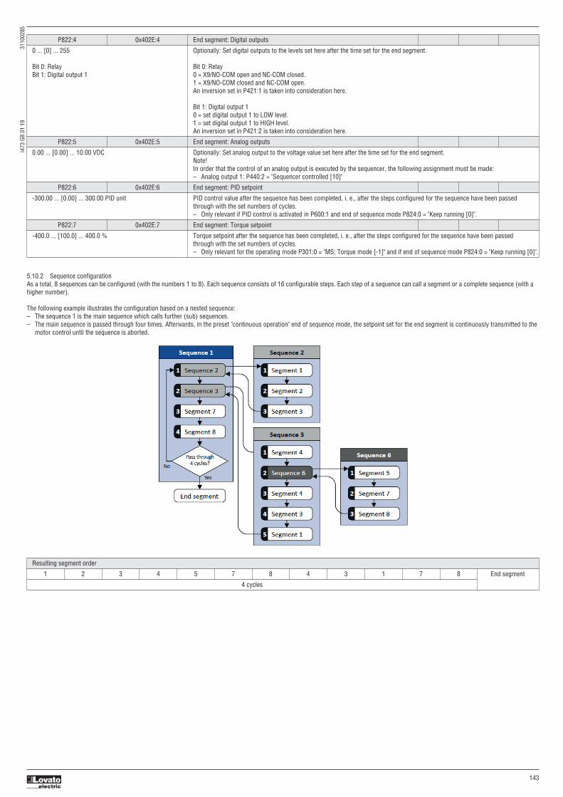
I473
GB
01 1
9
3
1100
285
143
P822:4 0x402E:4 End segment: Digital outputs
0 ... [0] ... 255 Optionally: Set digital outputs to the levels set here after the time set for the end segment.
Bit 0: Relay Bit 0: Relay Bit 1: Digital output 1 0 = X9/NO-COM open and NC-COM closed. 1 = X9/NO-COM closed and NC-COM open. An inversion set in P421:1 is taken into consideration here.
Bit 1: Digital output 1 0 = set digital output 1 to LOW level. 1 = set digital output 1 to HIGH level. An inversion set in P421:2 is taken into consideration here.
P822:5 0x402E:5 End segment: Analog outputs
0.00 ... [0.00] ... 10.00 VDC Optionally: Set analog output to the voltage value set here after the time set for the end segment. Note! In order that the control of an analog output is executed by the sequencer, the following assignment must be made: – Analog output 1: P440:2 = "Sequencer controlled [10]"
P822:6 0x402E:6 End segment: PID setpoint
-300.00 ... [0.00] ... 300.00 PID unit PID control value after the sequence has been completed, i. e., after the steps configured for the sequence have been passed through with the set numbers of cycles. – Only relevant if PID control is activated in P600:1 and end of sequence mode P824:0 = "Keep running [0]".
P822:7 0x402E:7 End segment: Torque setpoint
-400.0 ... [100.0] ... 400.0 % Torque setpoint after the sequence has been completed, i. e., after the steps configured for the sequence have been passed through with the set numbers of cycles. – Only relevant for the operating mode P301:0 = "MS: Torque mode [-1]" and if end of sequence mode P824:0 = "Keep running [0]".
Resulting segment order
1 2 3 4 5 7 8 4 3 1 7 8 End segment
4 cycles
5.10.2 Sequence configurationAs a total, 8 sequences can be configured (with the numbers 1 to 8). Each sequence consists of 16 configurable steps. Each step of a sequence can call a segment or a complete sequence (with ahigher number).
The following example illustrates the configuration based on a nested sequence:– The sequence 1 is the main sequence which calls further (sub) sequences.– The main sequence is passed through four times. Afterwards, in the preset "continuous operation" end of sequence mode, the setpoint set for the end segment is continuously transmitted to the
motor control until the sequence is aborted.

I473
GB
01 1
9
3
1100
285
144
Require parameter setting:
In the following, all parameters relevant for the sequence configuration are given.
If the sequencer is active, write accessed to all parameters are blocked that concern the active sequence configuration!i
Sequence 1 Sequence 2
Step 1 P830:1 = “Sequence 2 [-2]” P835:1 = “Segment 1 [1]”
Step 2 P830:2 = “Sequence 3 [-3]” P835:2 = “Segment 2 [2]”
Step 3 P830:3 = “Segment 7 [7]” P835:3 = “Segment 3 [3]”
Step 4 P830:4 = “Segment 8 [8]” P835:4 = “Skip step [0]”
Step 5 P830:5 = “Skip step [0]” …
Step … …
Step 16 P830:16 = Skip step [0]” P835:16 = Skip step [0]”
Number of cycles P831:0 = 4 P836:0 = 1
Sequence 3 Sequence 6
Step 1 P840:1 = “Segment 4 [4]” P855:1 = “Segment 5 [5]”
Step 2 P840:2 = “Sequence 6 [-6]” P855:2 = “Segment 7 [7]”
Step 3 P840:3 = “Segment 4 [4]” P855:3 = “Segment 8 [8]”
Step 4 P840:4 = “Segment 3 [3]” P855:4 = “Skip step [0]”
Step 5 P840:5 = “Segment 1 [1]”
Step 6 P840:6 = Skip step [0]” …
Step … …
Step 16 P840:16 = Skip step [0]” P855:16 = Skip step [0]”
Number of cycles P841:0 = 1 P856:0 = 1
P830:1 0x4030:1 Sequence 1: Step 1
-8 : Sequence 8 Configuration of the step 1 for sequence 1. -7 : Sequence 7 – Alternatively to calling a single segment, a complete sequence (with a higher number) can also be called from one step. -6: Sequence 6 This, for instance, serves to configure a main sequence from which several subsequences are called successively. -5 : Sequence 5 – With the setting "0", the respective step is skipped. -4 : Sequence 4 -3 : Sequence 3 -2: Sequence 2 0: Skip step 1: Segment 1 2: Segment 2 3: Segment 3 4: Segment 4 5: Segment 5 6: Segment 6 7: Segment 7 8: Segment 8
P830:2 0x4030:2 Sequence 1: Step 2
0: Skip step Configuration of the step 2 for sequence 1. (Reference: see P830:1)
P830:3 0x4030:3 Sequence 1: Step 3
0: Skip step Configuration of the step 3 for sequence 1. (Reference: see P830:1)
P830:4 0x4030:4 Sequence 1: Step 4
0: Skip step Configuration of the step 4 for sequence 1. (Reference: see P830:1)
P830:5 0x4030:5 Sequence 1: Step 5
0: Skip step Configuration of the step 5 for sequence 1. (Reference: see P830:1)
P830:6 0x4030:6 Sequence 1: Step 6
0: Skip step Configuration of the step 6 for sequence 1. (Reference: see P830:1)
P830:7 0x4030:7 Sequence 1: Step 7
0: Skip step Configuration of the step 7 for sequence 1. (Reference: see P830:1)
P830:8 0x4030:8 Sequence 1: Step 8
0: Skip step Configuration of the step 8 for sequence 1. (Reference: see P830:1)
P830:9 0x4030:9 Sequence 1: Step 9
0: Skip step Configuration of the step 9 for sequence 1. (Reference: see P830:1)
P830:10 0x4030:10 Sequence 1: Step 10
0: Skip step Configuration of the step 10 for sequence 1. (Reference: see P830:1)
P830:11 0x4030:11 Sequence 1: Step 11
0: Skip step Configuration of the step 11 for sequence 1. (Reference: see P830:1)
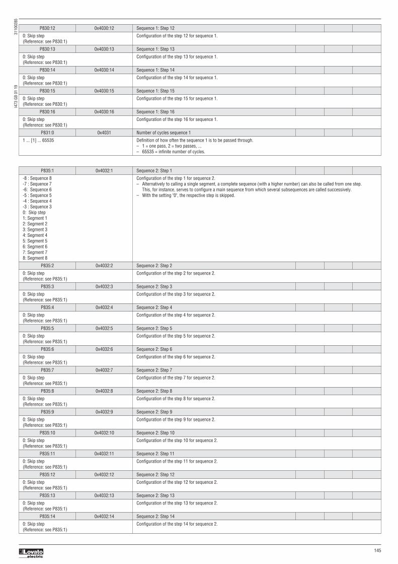
I473
GB
01 1
9
3
1100
285
145
P830:12 0x4030:12 Sequence 1: Step 12
0: Skip step Configuration of the step 12 for sequence 1. (Reference: see P830:1)
P830:13 0x4030:13 Sequence 1: Step 13
0: Skip step Configuration of the step 13 for sequence 1. (Reference: see P830:1)
P830:14 0x4030:14 Sequence 1: Step 14
0: Skip step Configuration of the step 14 for sequence 1. (Reference: see P830:1)
P830:15 0x4030:15 Sequence 1: Step 15
0: Skip step Configuration of the step 15 for sequence 1. (Reference: see P830:1)
P830:16 0x4030:16 Sequence 1: Step 16
0: Skip step Configuration of the step 16 for sequence 1. (Reference: see P830:1)
P831:0 0x4031 Number of cycles sequence 1
1 ... [1] ... 65535 Definition of how often the sequence 1 is to be passed through. – 1 = one pass, 2 = two passes, ... – 65535 = infinite number of cycles.
P835:1 0x4032:1 Sequence 2: Step 1
-8 : Sequence 8 Configuration of the step 1 for sequence 2. -7 : Sequence 7 – Alternatively to calling a single segment, a complete sequence (with a higher number) can also be called from one step. -6: Sequence 6 This, for instance, serves to configure a main sequence from which several subsequences are called successively. -5 : Sequence 5 – With the setting "0", the respective step is skipped. -4 : Sequence 4 -3 : Sequence 3 0: Skip step 1: Segment 1 2: Segment 2 3: Segment 3 4: Segment 4 5: Segment 5 6: Segment 6 7: Segment 7 8: Segment 8
P835:2 0x4032:2 Sequence 2: Step 2
0: Skip step Configuration of the step 2 for sequence 2. (Reference: see P835:1)
P835:3 0x4032:3 Sequence 2: Step 3
0: Skip step Configuration of the step 3 for sequence 2. (Reference: see P835:1)
P835:4 0x4032:4 Sequence 2: Step 4
0: Skip step Configuration of the step 4 for sequence 2. (Reference: see P835:1)
P835:5 0x4032:5 Sequence 2: Step 5
0: Skip step Configuration of the step 5 for sequence 2. (Reference: see P835:1)
P835:6 0x4032:6 Sequence 2: Step 6
0: Skip step Configuration of the step 6 for sequence 2. (Reference: see P835:1)
P835:7 0x4032:7 Sequence 2: Step 7
0: Skip step Configuration of the step 7 for sequence 2. (Reference: see P835:1)
P835:8 0x4032:8 Sequence 2: Step 8
0: Skip step Configuration of the step 8 for sequence 2. (Reference: see P835:1)
P835:9 0x4032:9 Sequence 2: Step 9
0: Skip step Configuration of the step 9 for sequence 2. (Reference: see P835:1)
P835:10 0x4032:10 Sequence 2: Step 10
0: Skip step Configuration of the step 10 for sequence 2. (Reference: see P835:1)
P835:11 0x4032:11 Sequence 2: Step 11
0: Skip step Configuration of the step 11 for sequence 2. (Reference: see P835:1)
P835:12 0x4032:12 Sequence 2: Step 12
0: Skip step Configuration of the step 12 for sequence 2. (Reference: see P835:1)
P835:13 0x4032:13 Sequence 2: Step 13
0: Skip step Configuration of the step 13 for sequence 2. (Reference: see P835:1)
P835:14 0x4032:14 Sequence 2: Step 14
0: Skip step Configuration of the step 14 for sequence 2. (Reference: see P835:1)

I473
GB
01 1
9
3
1100
285
146
P835:15 0x4032:15 Sequence 2: Step 15
0: Skip step Configuration of the step 15 for sequence 2. (Reference: see P835:1)
P835:16 0x4032:16 Sequence 2: Step 16
0: Skip step Configuration of the step 16 for sequence 2. (Reference: see P835:1)
P836:0 0x403 Number of cycles sequence 2
1 ... [1] ... 65535 Definition of how often the sequence 2 is to be passed through. – 1 = one pass, 2 = two passes, ... – 65535 = infinite number of cycles.
P840:1 0x4034:1 Sequence 3: Step 1
-8 : Sequence 8 Configuration of the step 1 for sequence 3. -7 : Sequence 7 – Alternatively to calling a single segment, a complete sequence (with a higher number) can also be called from one step. -6: Sequence 6 This, for instance, serves to configure a main sequence from which several subsequences are called successively. -5 : Sequence 5 – With the setting "0", the respective step is skipped. -4 : Sequence 4 0: Skip step 1: Segment 1 2: Segment 2 3: Segment 3 4: Segment 4 5: Segment 5 6: Segment 6 7: Segment 7 8: Segment 8
P840:2 0x4034:2 Sequence 3: Step 2
0: Skip step Configuration of the step 2 for sequence 3. (Reference: see P840:1)
P840:3 0x4034:3 Sequence 3: Step 3
0: Skip step Configuration of the step 3 for sequence 3. (Reference: see P840:1)
P840:4 0x4034:4 Sequence 3: Step 4
0: Skip step Configuration of the step 4 for sequence 3. (Reference: see P840:1)
P840:5 0x4034:5 Sequence 3: Step 5
0: Skip step Configuration of the step 5 for sequence 3. (Reference: see P840:1)
P840:6 0x4034:6 Sequence 3: Step 6
0: Skip step Configuration of the step 6 for sequence 3. (Reference: see P840:1)
P840:7 0x4034:7 Sequence 3: Step 7
0: Skip step Configuration of the step 7 for sequence 3. (Reference: see P840:1)
P840:8 0x4034:8 Sequence 3: Step 8
0: Skip step Configuration of the step 8 for sequence 3. (Reference: see P840:1)
P840:9 0x4034:9 Sequence 3: Step 9
0: Skip step Configuration of the step 9 for sequence 3. (Reference: see P840:1)
P840:10 0x4034:10 Sequence 3: Step 10
0: Skip step Configuration of the step 10 for sequence 3. (Reference: see P840:1)
P840:11 0x4034:11 Sequence 3: Step 11
0: Skip step Configuration of the step 11 for sequence 3. (Reference: see P840:1)
P840:12 0x4034:12 Sequence 3: Step 12
0: Skip step Configuration of the step 12 for sequence 3. (Reference: see P840:1)
P840:13 0x4034:13 Sequence 3: Step 13
0: Skip step Configuration of the step 13 for sequence 3. (Reference: see P840:1)
P840:14 0x4034:14 Sequence 3: Step 14
0: Skip step Configuration of the step 14 for sequence 3. (Reference: see P840:1)
P840:15 0x4034:15 Sequence 3: Step 15
0: Skip step Configuration of the step 15 for sequence 3. (Reference: see P840:1)
P840:16 0x4034:16 Sequence 3: Step 16
0: Skip step Configuration of the step 16 for sequence 3. (Reference: see P840:1)
P841:0 0x4035 Number of cycles sequence 3
1 ... [1] ... 65535 Definition of how often the sequence 3 is to be passed through. – 1 = one pass, 2 = two passes, ... – 65535 = infinite number of cycles.
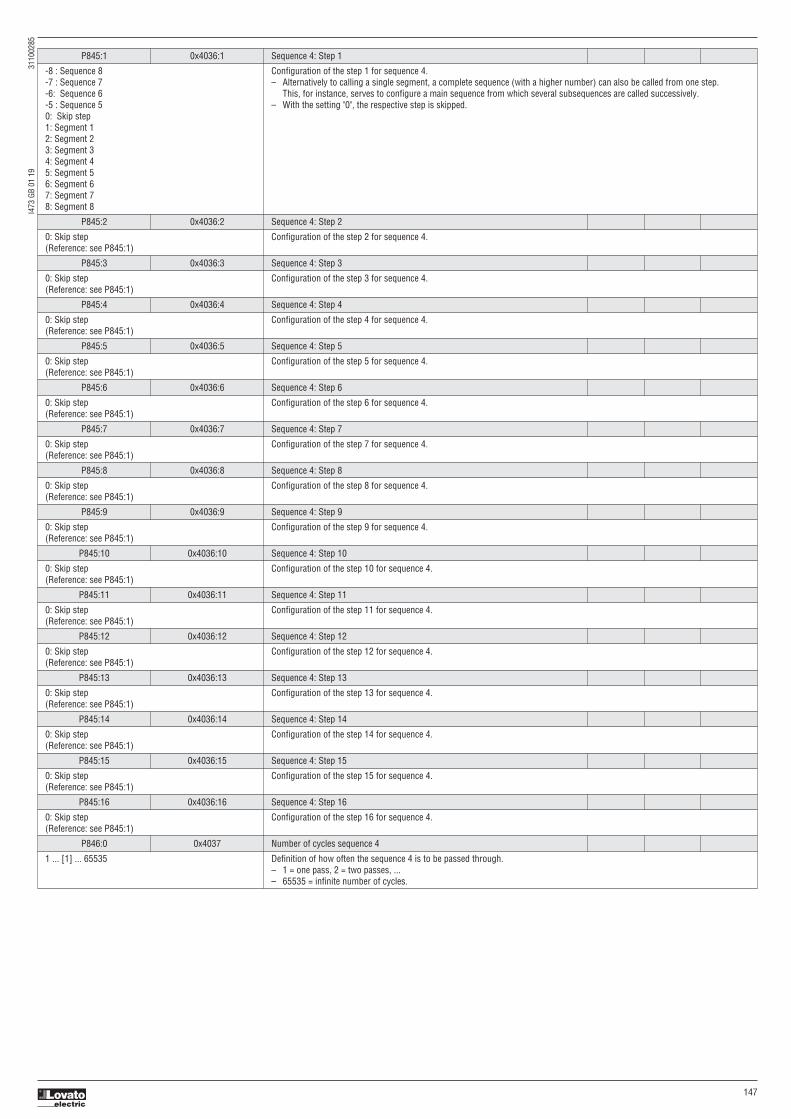
I473
GB
01 1
9
3
1100
285
147
P845:1 0x4036:1 Sequence 4: Step 1
-8 : Sequence 8 Configuration of the step 1 for sequence 4. -7 : Sequence 7 – Alternatively to calling a single segment, a complete sequence (with a higher number) can also be called from one step. -6: Sequence 6 This, for instance, serves to configure a main sequence from which several subsequences are called successively. -5 : Sequence 5 – With the setting "0", the respective step is skipped. 0: Skip step 1: Segment 1 2: Segment 2 3: Segment 3 4: Segment 4 5: Segment 5 6: Segment 6 7: Segment 7 8: Segment 8
P845:2 0x4036:2 Sequence 4: Step 2
0: Skip step Configuration of the step 2 for sequence 4. (Reference: see P845:1)
P845:3 0x4036:3 Sequence 4: Step 3
0: Skip step Configuration of the step 3 for sequence 4. (Reference: see P845:1)
P845:4 0x4036:4 Sequence 4: Step 4
0: Skip step Configuration of the step 4 for sequence 4. (Reference: see P845:1)
P845:5 0x4036:5 Sequence 4: Step 5
0: Skip step Configuration of the step 5 for sequence 4. (Reference: see P845:1)
P845:6 0x4036:6 Sequence 4: Step 6
0: Skip step Configuration of the step 6 for sequence 4. (Reference: see P845:1)
P845:7 0x4036:7 Sequence 4: Step 7
0: Skip step Configuration of the step 7 for sequence 4. (Reference: see P845:1)
P845:8 0x4036:8 Sequence 4: Step 8
0: Skip step Configuration of the step 8 for sequence 4. (Reference: see P845:1)
P845:9 0x4036:9 Sequence 4: Step 9
0: Skip step Configuration of the step 9 for sequence 4. (Reference: see P845:1)
P845:10 0x4036:10 Sequence 4: Step 10
0: Skip step Configuration of the step 10 for sequence 4. (Reference: see P845:1)
P845:11 0x4036:11 Sequence 4: Step 11
0: Skip step Configuration of the step 11 for sequence 4. (Reference: see P845:1)
P845:12 0x4036:12 Sequence 4: Step 12
0: Skip step Configuration of the step 12 for sequence 4. (Reference: see P845:1)
P845:13 0x4036:13 Sequence 4: Step 13
0: Skip step Configuration of the step 13 for sequence 4. (Reference: see P845:1)
P845:14 0x4036:14 Sequence 4: Step 14
0: Skip step Configuration of the step 14 for sequence 4. (Reference: see P845:1)
P845:15 0x4036:15 Sequence 4: Step 15
0: Skip step Configuration of the step 15 for sequence 4. (Reference: see P845:1)
P845:16 0x4036:16 Sequence 4: Step 16
0: Skip step Configuration of the step 16 for sequence 4. (Reference: see P845:1)
P846:0 0x4037 Number of cycles sequence 4
1 ... [1] ... 65535 Definition of how often the sequence 4 is to be passed through. – 1 = one pass, 2 = two passes, ... – 65535 = infinite number of cycles.

I473
GB
01 1
9
3
1100
285
148
P850:1 0x4038:1 Sequence 5: Step 1
-8 : Sequence 8 Configuration of the step 1 for sequence 5. -7 : Sequence 7 – Alternatively to calling a single segment, a complete sequence (with a higher number) can also be called from one step. -6: Sequence 6 This, for instance, serves to configure a main sequence from which several subsequences are called successively. 0: Skip step – With the setting "0", the respective step is skipped. 1: Segment 1 2: Segment 2 3: Segment 3 4: Segment 4 5: Segment 5 6: Segment 6 7: Segment 7 8: Segment 8
P850:2 0x4038:2 Sequence 5: Step 2
0: Skip step Configuration of the step 2 for sequence 5. (Reference: see P850:1)
P850:3 0x4038:3 Sequence 5: Step 3
0: Skip step Configuration of the step 3 for sequence 5. (Reference: see P850:1)
P850:4 0x4038:4 Sequence 5: Step 4
0: Skip step Configuration of the step 4 for sequence 5. (Reference: see P850:1)
P850:5 0x4038:5 Sequence 5: Step 5
0: Skip step Configuration of the step 5 for sequence 5. (Reference: see P850:1)
P850:6 0x4038:6 Sequence 5: Step 6
0: Skip step Configuration of the step 6 for sequence 5. (Reference: see P850:1)
P850:7 0x4038:7 Sequence 5: Step 7
0: Skip step Configuration of the step 7 for sequence 5. (Reference: see P850:1)
P850:8 0x4038:8 Sequence 5: Step 8
0: Skip step Configuration of the step 8 for sequence 5. (Reference: see P850:1)
P850:9 0x4038:9 Sequence 5: Step 9
0: Skip step Configuration of the step 9 for sequence 5. (Reference: see P850:1)
P850:10 0x4038:10 Sequence 5: Step 10
0: Skip step Configuration of the step 10 for sequence 5. (Reference: see P850:1)
P850:11 0x4038:11 Sequence 5: Step 11
0: Skip step Configuration of the step 11 for sequence 5. (Reference: see P850:1)
P850:12 0x4038:12 Sequence 5: Step 12
0: Skip step Configuration of the step 12 for sequence 5. (Reference: see P850:1)
P850:13 0x4038:13 Sequence 5: Step 13
0: Skip step Configuration of the step 13 for sequence 5. (Reference: see P850:1)
P850:14 0x4038:14 Sequence 5: Step 14
0: Skip step Configuration of the step 14 for sequence 5. (Reference: see P850:1)
P850:15 0x4038:15 Sequence 5: Step 15
0: Skip step Configuration of the step 15 for sequence 5. (Reference: see P850:1)
P850:16 0x4038:16 Sequence 5: Step 16
0: Skip step Configuration of the step 16 for sequence 5. (Reference: see P850:1)
P851:0 0x4039 Number of cycles sequence 5
1 ... [1] ... 65535 Definition of how often the sequence 5 is to be passed through. – 1 = one pass, 2 = two passes, ... – 65535 = infinite number of cycles.

I473
GB
01 1
9
3
1100
285
149
P855:1 0x403A:1 Sequence 6: Step 1
-8 : Sequence 8 Configuration of the step 1 for sequence 6. -7 : Sequence 7 – Alternatively to calling a single segment, a complete sequence (with a higher number) can also be called from one step. 0: Skip step This, for instance, serves to configure a main sequence from which several subsequences are called successively. 1: Segment 1 – With the setting "0", the respective step is skipped. 2: Segment 2 3: Segment 3 4: Segment 4 5: Segment 5 6: Segment 6 7: Segment 7 8: Segment 8
P855:2 0x403A:2 Sequence 6: Step 2
0: Skip step Configuration of the step 2 for sequence 6. (Reference: see P855:1)
P855:3 0x403A:3 Sequence 6: Step 3
0: Skip step Configuration of the step 3 for sequence 6. (Reference: see P855:1)
P855:4 0x403A:4 Sequence 6: Step 4
0: Skip step Configuration of the step 4 for sequence 6. (Reference: see P855:1)
P855:5 0x403A:5 Sequence 6: Step 5
0: Skip step Configuration of the step 5 for sequence 6. (Reference: see P855:1)
P855:6 0x403A:6 Sequence 6: Step 6
0: Skip step Configuration of the step 6 for sequence 6. (Reference: see P855:1)
P855:7 0x403A:7 Sequence 6: Step 7
0: Skip step Configuration of the step 7 for sequence 6. (Reference: see P855:1)
P855:8 0x403A:8 Sequence 6: Step 8
0: Skip step Configuration of the step 8 for sequence 6. (Reference: see P855:1)
P855:9 0x403A:9 Sequence 6: Step 9
0: Skip step Configuration of the step 9 for sequence 6. (Reference: see P855:1)
P855:10 0x403A:10 Sequence 6: Step 10
0: Skip step Configuration of the step 10 for sequence 6. (Reference: see P855:1)
P855:11 0x403A:11 Sequence 6: Step 11
0: Skip step Configuration of the step 11 for sequence 6. (Reference: see P855:1)
P855:12 0x403A:12 Sequence 6: Step 12
0: Skip step Configuration of the step 12 for sequence 6. (Reference: see P855:1)
P855:13 0x403A:13 Sequence 6: Step 13
0: Skip step Configuration of the step 13 for sequence 6. (Reference: see P855:1)
P855:14 0x403A:14 Sequence 6: Step 14
0: Skip step Configuration of the step 14 for sequence 6. (Reference: see P855:1)
P855:15 0x403A:15 Sequence 6: Step 15
0: Skip step Configuration of the step 15 for sequence 6. (Reference: see P855:1)
P855:16 0x403A:16 Sequence 6: Step 16
0: Skip step Configuration of the step 16 for sequence 6. (Reference: see P855:1)
P856:0 0x403B Number of cycles sequence 6
1 ... [1] ... 65535 Definition of how often the sequence 6 is to be passed through. – 1 = one pass, 2 = two passes, ... – 65535 = infinite number of cycles.

I473
GB
01 1
9
3
1100
285
150
P860:1 0x403C:1 Sequence 7: Step 1
-8 : Sequence 8 Configuration of the step 1 for sequence 7. 0: Skip step – Alternatively to calling a single segment, a complete sequence (with a higher number) can also be called from one step. 1: Segment 1 This, for instance, serves to configure a main sequence from which several subsequences are called successively. 2: Segment 2 – With the setting "0", the respective step is skipped. 3: Segment 3 4: Segment 4 5: Segment 5 6: Segment 6 7: Segment 7 8: Segment 8
P860:2 0x403C:2 Sequence 7: Step 2
0: Skip step Configuration of the step 2 for sequence 7. (Reference: see P860:1)
P860:3 0x403C:3 Sequence 7: Step 3
0: Skip step Configuration of the step 3 for sequence 7. (Reference: see P860:1)
P860:4 0x403C:4 Sequence 7: Step 4
0: Skip step Configuration of the step 4 for sequence 7. (Reference: see P860:1)
P860:5 0x403C:5 Sequence 7: Step 5
0: Skip step Configuration of the step 5 for sequence 7. (Reference: see P860:1)
P860:6 0x403C:6 Sequence 7: Step 6
0: Skip step Configuration of the step 6 for sequence 7. (Reference: see P860:1)
P860:7 0x403C:7 Sequence 7: Step 7
0: Skip step Configuration of the step 7 for sequence 7. (Reference: see P860:1)
P860:8 0x403C:8 Sequence 7: Step 8
0: Skip step Configuration of the step 8 for sequence 7. (Reference: see P860:1)
P860:9 0x403C:9 Sequence 7: Step 9
0: Skip step Configuration of the step 9 for sequence 7. (Reference: see P860:1)
P860:10 0x403C:10 Sequence 7: Step 10
0: Skip step Configuration of the step 10 for sequence 7. (Reference: see P860:1)
P860:11 0x403C:11 Sequence 7: Step 11
0: Skip step Configuration of the step 11 for sequence 7. (Reference: see P860:1)
P860:12 0x403C:12 Sequence 7: Step 12
0: Skip step Configuration of the step 12 for sequence 7. (Reference: see P860:1)
P860:13 0x403C:13 Sequence 7: Step 13
0: Skip step Configuration of the step 13 for sequence 7. (Reference: see P860:1)
P860:14 0x403C:14 Sequence 7: Step 14
0: Skip step Configuration of the step 14 for sequence 7. (Reference: see P860:1)
P860:15 0x403C:15 Sequence 7: Step 15
0: Skip step Configuration of the step 15 for sequence 7. (Reference: see P860:1)
P860:16 0x403C:16 Sequence 7: Step 16
0: Skip step Configuration of the step 16 for sequence 7. (Reference: see P860:1)
P861:0 0x403D Number of cycles sequence 7
1 ... [1] ... 65535 Definition of how often the sequence 7 is to be passed through. – 1 = one pass, 2 = two passes, ... – 65535 = infinite number of cycles.

I473
GB
01 1
9
3
1100
285
151
P865:1 0x403E:1 Sequence 8: Step 1
0: Skip step Configuration of the step 1 for sequence 8. 1: Segment 1 – Alternatively to calling a single segment, a complete sequence (with a higher number) can also be called from one step. 2: Segment 2 This, for instance, serves to configure a main sequence from which several subsequences are called successively. 3: Segment 3 – With the setting "0", the respective step is skipped. 4: Segment 4 5: Segment 5 6: Segment 6 7: Segment 7 8: Segment 8
P865:2 0x403E:2 Sequence 8: Step 2
0: Skip step Configuration of the step 2 for sequence 8. (Reference: see P865:1)
P865:3 0x403E:3 Sequence 8: Step 3
0: Skip step Configuration of the step 3 for sequence 8. (Reference: see P865:1)
P865:4 0x403E:4 Sequence 8: Step 4
0: Skip step Configuration of the step 4 for sequence 8. (Reference: see P865:1)
P865:5 0x403E:5 Sequence 8: Step 5
0: Skip step Configuration of the step 5 for sequence 8. (Reference: see P865:1)
P865:6 0x403E:6 Sequence 8: Step 6
0: Skip step Configuration of the step 6 for sequence 8. (Reference: see P865:1)
P865:7 0x403E:7 Sequence 8: Step 7
0: Skip step Configuration of the step 7 for sequence 8. (Reference: see P865:1)
P865:8 0x403E:8 Sequence 8: Step 8
0: Skip step Configuration of the step 8 for sequence 8. (Reference: see P865:1)
P865:9 0x403E:9 Sequence 8: Step 9
0: Skip step Configuration of the step 9 for sequence 8. (Reference: see P865:1)
P865:10 0x403E:10 Sequence 8: Step 10
0: Skip step Configuration of the step 10 for sequence 8. (Reference: see P865:1)
P865:11 0x403E:11 Sequence 8: Step 11
0: Skip step Configuration of the step 11 for sequence 8. (Reference: see P865:1)
P865:12 0x403E:12 Sequence 8: Step 12
0: Skip step Configuration of the step 12 for sequence 8. (Reference: see P865:1)
P865:13 0x403E:13 Sequence 8: Step 13
0: Skip step Configuration of the step 13 for sequence 8. (Reference: see P865:1)
P865:14 0x403E:14 Sequence 8: Step 14
0: Skip step Configuration of the step 14 for sequence 8. (Reference: see P865:1)
P865:15 0x403E:15 Sequence 8: Step 15
0: Skip step Configuration of the step 15 for sequence 8. (Reference: see P865:1)
P865:16 0x403E:16 Sequence 8: Step 16
0: Skip step Configuration of the step 16 for sequence 8. (Reference: see P865:1)
P866:0 0x403F Number of cycles sequence 8
1 ... [1] ... 65535 Definition of how often the sequence 8 is to be passed through. – 1 = one pass, 2 = two passes, ... – 65535 = infinite number of cycles.

I473
GB
01 1
9
3
1100
285
152
5.10.3 Sequencer basic settingsIn the presetting, the sequencer is disabled. In order to enable the sequencer, the desired sequencer mode (time and/or step operation) must be set. Moreover, different end of sequence modes andstart of sequences modes are available.
Sequencer mode (P800:0)– The sequencer can be operated in time and/or step operation.– The following diagram demonstrates the different sequencer modes:
End of sequence mode (P824:0)– The end of sequence mode defines the action after the end of the sequence.– In the default setting "Keep running [0]", the setpoint set for the end segment is continuously transmitted to the motor control until the sequence is aborted.– The following diagram demonstrates the different end of sequence modes:
Start of sequence mode (P820:0)– The start of sequence mode defines the action after the motor is stopped and restarted or after the motor has been restarted after an error occurred.– In the default setting "Restart sequencer [0]", the currently selected sequence is restarted.– The following diagram demonstrates the different start of sequence modes:

I473
GB
01 1
9
3
1100
285
153
P800:0 0x4025 Sequencer mode
0: Disabled Selection of the sequencer mode. 1: Time operation 2: Step operation 0: Disabled 3: Time & step operation 1: Time operation The switch-over to the next step of the sequence is made after the time set for the current segment has elapsed.
2: Step operation The switch-over to the next step of the sequence is made via the trigger assigned in P400.32 to the "Next sequence step" function.
3: Time & step operation The switch-over to the next step of the sequence is made via the trigger assigned in P400.32 to the "Next sequence step" function, but no later than after the time set for the current segment has elapsed.
P824:0 0x402F End of sequence mode
0: Keep running Selection of the action after the sequence has been completed, i. e., after the steps configured for the sequence have been passed 1: Stop through with the set numbers of cycles. 2: Stop and abort 3: Abort 0: Keep running The setpoint set for the end segment is continuously transmitted to the motor control until the sequence is aborted.
1: Stop The motor is stopped with the stop method set in P203:3. The setpoint is continued to be controlled by the sequencer. In order to return to the normal setpoint control, the sequence must be aborted. Note! After returning to the normal setpoint control, a start command is required to restart the motor.
2: Stop and abort The motor is stopped with the stop method set in P203:3. After standstill is reached, it is automatically returned to the normal setpoint control. Note! After returning to the normal setpoint control, a start command is required to restart the motor.
3: Abort Return to the normal setpoint control without stopping the motor.
P820:0 0x4040 Start of sequence mode
0: Restart sequencer Selection of the action after the motor has been stopped and restarted or after the motor has been restarted after an error occurred. 1: Restart current segment 2: Continue current segment 0: Restart sequencer 3: Start next segment The currently selected sequence is restarted. 4: No action 1: Restart current segment The current segment of the selected sequence is restarted.
2: Continue current segment The current segment of the selected sequence is continued (just like after a break).
3: Start next segment The next segment of the selected sequence is started.
4: No action For debugging purposes: The sequence is continued to be processed (including output states) even if the motor is stopped.
5.10.4 Sequencer control functionsThe following functions serve to control the sequencer.
Select sequenceA sequence is selected in a binary-coded fashion via the triggers assigned to the four functions "Select sequence (bit 0)" ... " Select sequence (bit 3)" in compliance with the following truth table:
Select sequence Selection
Bit 3 Bit 2 Bit 1 Bit 0 P400:53 P400:52 P400:51 P400:50
FALSE FALSE FALSE FALSE No sequence selected
FALSE FALSE FALSE TRUE Sequence 1
FALSE FALSE TRUE FALSE Sequence 2
FALSE FALSE TRUE TRUE Sequence 3
FALSE TRUE FALSE FALSE Sequence 4
FALSE TRUE FALSE TRUE Sequence 5
FALSE TRUE TRUE FALSE Sequence 6
FALSE TRUE TRUE TRUE Sequence 7
TRUE FALSE FALSE FALSE Sequence 8
TRUE FALSE FALSE TRUE
… Invalid selection
TRUE TRUE TRUE TRUE

I473
GB
01 1
9
3
1100
285
154
Start sequenceThe selected sequence is not started automatically. For starting the sequence, two functions are available:– P400:30: Run/abort sequence (status-controlled start)– P400:31: Start sequence (edge-controlled start)
Further control functionsThe following functions serve to control the started sequence:– P400:32: Next sequence step– P400:33: Pause sequence– P400:34: Suspend sequence– P400:35: Stop sequence– P400:36: Abort sequenceFor controlling the sequencer via network, the sequencer control functions can also be assigned to the NetWordIN1 data word P590:1.
P400:30 0x2631:030 Run/abort sequence
0: Not connected Assignment of a trigger for the "Run/abort sequence" function. (Reference see P400:1) Trigger = TRUE: Start selected sequence. Trigger = FALSE: Abort sequence. Notes: – The assigned trigger must remain set to TRUE for the duration of the sequence. – If the trigger bit is reset to FALSE, the sequence is aborted. In this case, the standard setpoint or the setpoint source selected via setpoint change-over is active again. – A sequence is selected in a binary-coded fashion via the trigger assigned to the four functions "Select sequence (bit 0)" P400:50 ... "Select sequence (bit 3)" P400:53. – For an edge-controlled start, the function "Start sequence" P400:31 is optionally available.
P400:31 0x2631:031 Start sequence
0: Not connected Assignment of a trigger for the "Start sequence" function. (Reference see P400:1) Trigger = FALSETRUE (edge): Start selected sequence. Trigger = TRUEFALSE (edge): No action. Notes: – After the start, the sequencer remains activated until the function "Stop sequence" P400:35 or the function "Abort sequence" P400:36 is executed. A normal stop command does not reset the start command for the sequencer. – For a status-controlled start, the function "Run/abort sequence" P400:30 is optionally available.
P400:32 0x2631:032 Next sequence step
0: Not connected Assignment of a trigger for the "Next sequence step" function. (Reference see P400:1) Trigger = FALSETRUE (edge): Next sequence step. Trigger = TRUEFALSE (edge): No action. Notes: – The execution of the current step is completed even if the time parameterized for the segment has not elapsed yet. – The function is only relevant for Sequencer mode P800:0 ="Step operation [2]" or "Time & step operation [3]". – A jump to the next sequence step is not possible if the sequence pauses, the sequence is suspended or the final segment is executed.
P400:33 0x2631:033 Pause sequence
0: Not connected Assignment of a trigger for the "Pause sequence" function. (Reference see P400:1) Trigger = TRUE: Pause sequence. Trigger = FALSE: Continue sequence. Notes: – During the pause, the sequence stops in the current step. The expiration of the time set for the segment is stopped. – The sequencer setpoint continues to remain active.
P400:34 0x2631:034 Suspend sequence
0: Not connected Assignment of a trigger for the "Suspend sequence" function. (Reference see P400:1) Trigger = TRUE: Suspend sequence. Trigger = FALSE: Continue sequence. Notes: – This function serves to temporarily change over to the standard setpoint or the setpoint source selected via setpoint change-over. – The sequence is continued at the point where it was suspended.
P400:35 0x2631:035 Stop sequence
0: Not connected Assignment of a trigger for the "Stop sequence" function. (Reference see P400:1) Trigger = FALSETRUE (edge): Stop sequence. Trigger = TRUEFALSE (edge): No action. Notes: – If the sequence is stopped, it is jumped to the final segment. – The further execution depends on the selected End of sequence mode P824:0.
P400:36 0x2631:036 Abort sequence
0: Not connected Assignment of a trigger for the "Abort sequence" function. (Reference see P400:1) Trigger = FALSETRUE (edge): Abort sequence. Trigger = TRUEFALSE (edge): No action. Notes: – This function serves to directly stop the sequence without the final segment being executed. In this case, the standard setpoint or the setpoint source selected via setpoint change-over is active again.
P400:50 0x2631:050 Select sequence (bit 0)
0: Not connected Assignment of a trigger for the "Select sequence (bit 0)" function. (Reference see P400:1) Selection bit with the valency 20 for bit coded selection of a sequence. Trigger = FALSE: selection bit = "0". Trigger = TRUE: selection bit = "1". Notes: – The selected sequence is not started automatically. – For a status-controlled start, the function "Run/abort sequence" P400:30 is available. – For an edge-controlled start, the function "Start sequence" P400:31 is available.

I473
GB
01 1
9
3
1100
285
155
P400:51 0x2631:051 Select sequence (bit 1)
0: Not connected Assignment of a trigger for the "Select sequence (bit 1)" function. (Reference see P400:1) Selection bit with the valency 21 for the bit-coded selection of a sequence. Trigger = FALSE: selection bit = "0". Trigger = TRUE: selection bit = "1". Notes: – The selected sequence is not started automatically. – For a status-controlled start, the function "Run/abort sequence" P400:30 is available. – For an edge-controlled start, the function "Start sequence" P400:31 is available.
P400:52 0x2631:052 Select sequence (bit 2)
0: Not connected Assignment of a trigger for the "Select sequence (bit 2)" function. (Reference see P400:1) Selection bit with the valency 22 for the bit-coded selection of a sequence. Trigger = FALSE: selection bit = "0". Trigger = TRUE: selection bit = "1". Notes: – The selected sequence is not started automatically. – For a status-controlled start, the function "Run/abort sequence" P400:30 is available. – For an edge-controlled start, the function "Start sequence" P400:31 is available.
P400:53 0x2631:053 Select sequence (bit 3)
0: Not connected Assignment of a trigger for the "Select sequence (bit 3)" function. (Reference see P400:1) Selection bit with the valency 23 for the bit-coded selection of a sequence. Trigger = FALSE: selection bit = "0". Trigger = TRUE: selection bit = "1". Notes: – The selected sequence is not started automatically. – For a status-controlled start, the function "Run/abort sequence" P400:30 is available. – For an edge-controlled start, the function "Start sequence" P400:31 is available.
Parameter Name Setting for this example
P400:1 Enable VSD Constant TRUE [1]
P400:2 Run Digital input 1 [11]
P400:4 Reset fault Not connected [0]
P400:13 Invert rotation Not connected [0]
P400:31 Start sequence Digital input 2 [12]
P400:36 Abort sequence Digital input 3 [13]
P400:50 Select sequence (bit 0) Constant TRUE [1]
P420:1 Relay Sequencer controlled [100]
P420:2 Digital output 1 Sequencer controlled [100]
Segment and sequence configuration In this example, only the sequence 1 is used. The sequence consists of two steps (segment 1 and segment 2).
P801:1 Sequencer segment 1: Frequency setpoint 40 Hz
P801:2 Sequencer segment 1: Acceleration/deceleration 20 s
P801:3 Sequencer segment 1: Time 18 s
P801:4 Sequencer segment 1: Digital outputs 0x00
P802:1 Sequencer segment 2: Frequency setpoint 30 Hz
P802:2 Sequencer segment 2: Acceleration/deceleration 15 s
P802:3 Sequencer segment 2: Time 14 s
P802:4 Sequencer segment 2: Digital outputs 0x02 (only relay)
P822:1 End segment: Frequency setpoint 10 Hz
P822:2 End segment: Acceleration/deceleration 8 s
P822:3 End segment: Time 10 s
P822:4 End segment: Digital outputs 0x04 (only digital output 1)
P830:1 Sequence 1: Step 1 Segment 1 [1]
P830:2 Sequence 1: Step 2 Segment 2 [2]
Sequencer basic settings
P800:0 Sequencer mode Time operation [1]
P824:0 End of sequence mode Keep running [0]
P820:0 Start of sequence mode Restart sequencer [0]
Example of operating modeIn the following example, the digital inputs 2 and 3 are used for controlling the sequencer.– The analog input 1 is set as standard setpoint source.– Switch S1 starts the motor in forward direction of rotation. Switch S1 in the initial position stops the motor again.– Button S2 starts the sequence, button S3 aborts the sequence. After the abortion, the normal setpoint control is active again.
R1 = frequency setpoint selectionS1 = RunS2 = Start sequenceS3 = Abort sequence

I473
GB
01 1
9
3
1100
285
156
① If the VSD is enabled and no error is active, the motor can be started with the "Run" function. As the sequence has not been started yet, first the normal setpoint control is active.② The "Start sequence" function is used to start the selected sequence in an edge-controlled way.③ Sequencer mode P800:0 = "Time operation [1]": The switch-over to the next step of the sequence is made after the time set for the current segment has elapsed.④ The segment 2 is configured here in such a way that the relay will be triggered during the time of processing.⑤ End of sequence mode P824:0 = "Keep running [0]": After the sequence has been processed, the setpoint set for the end segment is continuously transmitted to the motor control until the sequence is aborted.⑥ In case of the end segment, the time setting determines the delay after which the configured output states are to become active. Here, the end segment is configured in such a way that the
digital output 1 is set after 10 s have expired.⑦ If the "Run" function is set to FALSE, the motor is stopped with the stop method set in P203:3. The started sequence, however, remains active and the sequencer-controlled outputs keep their
state.⑧ Start of sequence mode P820:0 = "Restart sequencer [0]": If the "Run" function is set to TRUE again, the (still active) sequence is restarted.⑨ The "Abort sequence" function is used to abort the sequence in an edge-controlled way. In this case, the standard setpoint or the setpoint source selected via setpoint change-over is active
again.

I473
GB
01 1
9
3
1100
285
157
6 TROUBLESHOOTING
6.1 LED STATUS DISPLAY
The "RDY" and "ERR" LED status displays on the front of the VSD provide some quick information about certain operating states.
“RDY” LED (blue) “ERR” LED (red) Status/meaning
off off No supply voltage.
Initialisation (VSD is started).
on on
Safe torque off (STO) active.
off
blinking (1 Hz) Safe torque off (STO) sctive, warning active.
blinking fast (4 Hz)
off VSD inhibited.
VSD disabled, warning active.
blinking fast (4 Hz)
VSD disabled, error active.
on
blinking (2 Hz) VSD inhibited, no DC-bus voltage.
lit every 1.5s for a short time
USB module is connected, 5-V supply voltage for the USB module is available.
on for a short time every 1s
off VSD enabled.
The motor rotates according to the specified setpoint or quick stop active.
VSD enabled.
on blinking fast (4 Hz) The motor rotates according to the specified setpoint or quick stop active.
VSD enabled, quick stop as response to fault active.
blinking (1 Hz)
Firmware update active.
Both LEDs are blinking in a rapidly alternating mode
“Visual tracking” function is active.
Both LEDs are blinking in a very rapidly synchronous mode
6.2 ERROR HANDLING
Many functions integrated in the VSD can:– detect errors and thus protect VSD and motor from damages,– detect an operating error of the user,– output a warning or information if desired.
6.2.1 Error typesIn the event of an error, the VSD response is determined by the error type defined for the error.In the following, the different error types are described.
Error type "No response"The error is completely ignored (does not affect the running process).
Error type "Warning"A warning does not severely affect the process and may be also ignored in consideration of safety aspects.
Error type "Fault"The motor is brought to a standstill with the quick stop ramp.– The VSD will only be disabled after the quick stop is executed (motor at standstill) or after the time-out time set in 0x2826 has been elapsed. – Exception: In case of a serious fault, the VSD is disabled immediately. The motor becomes torqueless (coasts). For details see the table "Error messages".
Error type "Trouble"Just like "Fault", but the error state will be left automatically if the error condition is not active anymore.– Exception: In case of a severe trouble, the VSD is disabled immediately. The motor becomes torqueless (coasts). For details see the table "Error messages ". – The restart behaviour after trouble can be configured.
In the operating mode P301:0 = "Velocity mode [2]", the behavior in case of "Trouble" is just like in case of "Fault".i

I473
GB
01 1
9
3
1100
285
158
Comparison of the error typesThe following table compares the main differences of the error types:
6.2.2 Error configurationThe errors can be divided into two types:– Errors with predefined error type– Errors with configurable error typeEspecially critical errors are permanently set to the "Fault" error type in order to protect VSD and motor from damages.In case of errors with configurable error type, the default setting can be changed in consideration of safety aspects and the operational performance. The selection "No response [0]" is, however,only available for minor errors.The "Error messages" table lists the error type for each error. If the error type can be configured by the user, the "adjustable in" column displays the corresponding parameter.
6.2.3 Error resetIf the error condition is not active anymore, there are several options to reset an active error and thus leave the error state again:– Via the keypad key . – Via the trigger assigned to the “Reset fault" function. – Via the button in the software VLBXSW01.– In the default setting of 0x400E:008 (P505:8) via bit 7 in the mappable data word NetWordIN1 0x4008:001 (P590:1).– Via bit 7 in the mappable CiA 402 control word 0x6040.– Via bit 2 in the mappable AC Drive control word 0x400B:001 (P592:1).– Via bit 11 in the mappable Lovato control word 0x400B:002 (P592:2).Notes:– Certain errors can only be reset by mains switching.– Certain errors (e. g. earth fault or short circuit of the motor phases) may cause a blocking time. In this case, the error can be reset only after the blocking time has elapsed. An active blocking
time is displayed via bit 14 in the VSD status word 0x2831.The "Error messages" table gives the blocking time (if available) for each error. This table also shows whether mains switching is required for the error reset.
6.2.4 Keypad error messagesIf an error is pending, the keypad shows the following information:
Error type Logging in the Display in the VSD disable Motor stop Error reset is “ERR” LED (red) Error history buffer CiA 402 status required / Logbook word 0x6041 (P780:0)
No response No No No No No off
Warning Yes Yes, bit 7 No No No
blinking fast (4 Hz)
Trouble Yes Yes, bit 3 After quick stop or Quick stop ramp or No
immediately. coasting. blinking (1 Hz)
Error Yes Yes, bit 3 For details see table “Error messages” Yes
on
① Error text② Error type: F=Fault, T=Trouble, W=Warning③ Error code (hexadecimal)
Faults (F) and troubles (T) are displayed continuously.Warnings (W) are only displayed every 2 seconds for a short time.
After a disturbance, a restart is possible if the error condition is not active anymore. The keypad shows this by the "Restart Pending" note. The note is displayed in a 1-secondinterval alternating with the error text.

I473
GB
01 1
9
3
1100
285
159
6.3 ERROR HISTORY
6.3.1 ERROR HISTORY KEYPAD
Any time the VSD experiences an Error condition during operation it is captured in the VSD non-volatile memory. For historical Error tracking purposes the Errors can be viewed in P155.00. Thisparameter contains the actual Error codes, the time (in running hours) that the Error occurred and the count of Errors (in case of multiple instances of the same Error condition). The Error Historywill retain the 32 most recent Errors.
The data in the Error History is described below:
6.3.2 ERROR HISTORY VLBXSW01 SOFTWARE
Opens the error logbook
Reset the drive error
Time Time of the fault occurrence based on “Operation time (Control unit)” P150.03. If more than one fault of the same type is counted (Count >1) the first fault occurrence time is shown! [dd:hh:mm:ss]
Type Error type (Warning, Error, Trouble)
Occurred in Occurrence of the event
CiA 402 Error code Error Code
Text Error text
Count Number of sequential fault occurrences

I473
GB
01 1
9
3
1100
285
160
6.4 ERROR MESSAGESThe following table contains all error codes of the VSD in ascending order.
8784 0x2250 CiA: Continuous over current (internal) Keypad display: PU over current
Cause Error type/response Remedy
– Continuous overcurrent on the VSD/ motor side. Fault – Check motor and wiring for short circuits. – Overcurrent at the brake chopper (brake transistor). – The VSD is inhibited immediately. – Check brake resistor and wiring. – DC bus relay has not been closed due to a malfunction. The motor becomes torqueless (coasts). – The error can only be reset after a blocking time.
Blocking time: 5 s
8992 0x2320 CiA: Short circuit/earth leakage (internal) Keypad display: Earth leak
Cause Error type/response Remedy
– Short circuit/earth fault of motor cable Fault – Check motor cable. – Capacitive charging current of the motor cable too high. – The VSD is inhibited immediately. – Check length of the motor cable. The motor becomes torqueless (coasts). – Use shorter or lower-capacitance motor cable. – The error can only be reset after a blocking time.
Blocking time: 5 s
9024 0x2340 CiA: Short circuit (device internal) Keypad display: Motor shorted
Cause Error type/response Remedy
Short circuit of motor cable Fault Check motor cable for short circuit. – The VSD is inhibited immediately. The motor becomes torqueless (coasts). – The error can only be reset after a blocking time.
Blocking time: 5 s
9040 0x2350 CiA: i²*t overload (thermal state) Keypad display: i2t motor
Cause Error type/response Remedy
Motor thermally overloaded, e. g. by an impermissible Fault (Configurable) – Check drive dimensioning. continuous current or by frequent or too long acceleration – The error can only be reset after a blocking time. – Check machine/driven mechanics for exces- sive load.
processes. Blocking time: 5 s
Setting parameters: P308:3
9090 0x2382 I*t error Keypad display: Ixt error
Cause Error type/response Remedy
Device utilisation (I*t) too high by frequent and too long Fault (Configurable) Check drive dimensioning. acceleration processes. – The error can only be reset after a blocking time.
Blocking time: 3 s
Setting parameters: P135:5
9091 0x2383 I*t warning Keypad display: Ixt warning
Cause Error type/response Remedy
Device utilisation (I*t) too high by frequent and too long Warning Check drive dimensioning. acceleration processes.
9095 0x2387 Imax: Clamp responded too often Keypad display: Clamp timeout
Cause Error type/response Remedy
Maximum current of the axis (display in 0x2DDF:002) Fault – Select a flatter speed ramp. has been reached too often in succession. – Reduce the load. – Set Imax controller more dynamically.
9096 0x2388 SL-PSM stall detection active Keypad display: SL-PSM stall det.
Cause Error type/response Remedy
Overload of the motor with sensorless control for Trouble – Reduce load at the axis. synchronous motors (SL-PSM). – The VSD is inhibited immediately. – Check settings of the SL-PSM parameters. The motor becomes torqueless (coasts).
9098 0x238A Maximum current reached Keypad display: Imax reached
Cause Error type/response Remedy
The current motor current P103:0 is equal to or Information – Reduce the load on the motor or change the settings for the higher than the max. overload current P324:0. maximum overload current. P324:0.
12576 0x3120 Mains phase fault Keypad display: Mains Phase fail
Cause Error type/response Remedy
Mains phase failure Fault – Check wiring of the mains connection. – Check fuses.

I473
GB
01 1
9
3
1100
285
161
12672 0x3180 UPS operation active Keypad display: UPS oper. active
Cause Error type/response Remedy
Operation on uninterrupted 1x230V current supply (UPS) Warning Switch back to operation with regular mains voltage. has been activated: Only a reduced output current is provided.
12816 0x3210 DC bus overvoltage Keypad display: DC Bus OV
Cause Error type/response Remedy
DC-bus voltage has exceeded the error threshold for Fault – Reduce dynamic performance of the load profile. overvoltage due to a too high braking energy or a too high – Check mains voltage. mains voltage. The error threshold (display in P208:6) – Check settings for brake energy management. results from the setting of the rated mains voltage – Connect brake resistor to the power unit and activate the in P208:1. integrated brake chopper.
12817 0x3211 DC bus overvoltage warning Keypad display: Warn.DC Bus OV
Cause Error type/response Remedy
DC-bus voltage has exceeded the warning threshold for Warning – Reduce dynamic performance of the load profile. overvoltage set in P208:5 due to a too high braking energy – Check mains voltage. or a too high mains voltage. – Check settings for brake energy management. – Connect brake resistor to the power unit and activate the integrated brake chopper.
12832 0x3220 DC bus undervoltage Keypad display: DC Bus UV
Cause Error type/response Remedy
DC-bus voltage has fallen below the error threshold for Trouble – Check mains voltage. undervoltage. The error threshold (display in P208:3) – Check DC-bus voltage. results from the setting of the rated mains voltage – Check mains settings. in P208:1.
12833 0x3221 DC bus undervoltage warning Keypad display: Warn.DC Bus UV
Cause Error type/response Remedy
DC-bus voltage has fallen below the warning threshold Warning – Check mains voltage. for undervoltage set in P208:2. – Check DC-bus voltage. – Check mains settings.
12834 0x3222 DC-bus voltage to low for power up Keypad display: DC-bus on-UV
Cause Error type/response Remedy
The input voltage is too low to switch on the VSD. Warning – Check mains voltage. – Check mains settings.
16912 0x4210 PU: overtemperature fault Keypad display: PU Overtemp.
Cause Error type/response Remedy
The heatsink temperature of the power unit Fault – Provide for a sufficient cooling of the device. (display in P117:1) has exceeded the fixed error threshold – Clean fan and ventilation slots. (100 °C). – If required, replace fan. – Ambient temperature too high. – Fan or ventilation slots are polluted. – Fan is defective.
17024 0x4280 Heat sink temperature sensor fault Keypad display: Heatsink sensor
Cause Error type/response Remedy
Sensor for the temperature monitoring of the power unit Fault Hardware error: it is necessary to contact the manufacturer, is defective. The failure of the temperature monitoring since the device must be replaced. function poses the risk of overheating!
17025 0x4281 Heat sink fan warning Keypad display: Heatsink fan
Cause Error type/response Remedy
Warning of the heatsink fan. Warning Check/replace the heatsink fan.
17029 0x4285 PU overtemperature warning Keypad display: Warn.PU Overtemp
Cause Error type/response Remedy
The heatsink temperature of the power unit Warning – Provide for a sufficient cooling of the device. (display in P117:1) has exceeded the warning threshold – Clean fan and ventilation slots. set in 0x2D84:002. – If required, replace fan. – Ambient temperature too high. – Fan or ventilation slots are polluted. – Fan is defective.

I473
GB
01 1
9
3
1100
285
162
17168 0x4310 Motor temperature error Keypad display: Overtemp. motor
Cause Error type/response Remedy
The motor temperature sensor connected to terminals Fault (Configurable) – Check drive dimensioning. X109/T1 and X109/T2 measures a too high motor – The error can only be reset after a blocking time. – Check motor temperature sensor and wiring. temperature. Blocking time: 5 s – Motor too hot by impermissibly high cur- rents.
Setting parameters: P309:2 – Motor too hot by frequent and too long acceleration processes.
20754 0x5112 24 V supply critical Keypad display: 24V supply low
Cause Error type/response Remedy
24V voltage failed or too low. Warning – Check optional external 24V voltage supply (terminal X3/24E), if connected. – Check mains voltage.
20864 0x5180 Overload 24 V supply Keypad display: Overlaod 24V
Cause Error type/response Remedy
Output current at the 24V output or at the digital outputs Warning Check 24V output and digital outputs for earth fault or overload. too high.
21376 0x5380 OEM hardware incompatible Keypad display: Incomp. OEM HW
Cause Error type/response Remedy
The control unit (OEM hardware) is not compatible Fault – Use compatible hardware. with the power unit (OEM hardware). – The VSD is inhibited immediately. – Contact the OEM. The motor becomes torqueless (coasts). – The error can only be reset by mains switching.
24970 0x618A Internal fan warning Keypad display: Internal fan
Cause Error type/response Remedy
Warning of the internal fan. Warning Check/replace internal fan.
25216 0x6280 Trigger/functions connected incorrectly Keypad display: P400 config err
Cause Error type/response Remedy
The assignment directives have not been observed. Trouble Check and correct the assignment of the trig- gers for the functions. – If the "flexible I/O configuration" is active as control – With keypad or network control, the two functions "Enable VSD" source, the "Enable VSD" or "Run" function must be and "Run" can also be set to "Constant TRUE [1]" to start the motor. connected to a digital input in order that the motor can be stopped again any time! – The use of the "Start forward (CW)" and "Start reverse (CCW)" functions excludes the use of the "Run forward (CW)" and "Run reverse (CCW)" functions, and vice versa.
25217 0x6281 User-defined fault 1 Keypad display: User fault 1
Cause Error type/response Remedy
Flexible I/O configuration: the "Activate fault 1" function Fault Eliminate error cause and then reset error. was activated via the trigger selected in P400:43.
25218 0x6282 User-defined fault 2 Keypad display: User fault 2
Cause Error type/response Remedy
Flexible I/O configuration: the "Activate fault 2" function Fault Eliminate error cause and then reset error. was activated via the trigger selected in P400:44.
25232 0x6290 Warning invert rotation Keypad display: Invert rotation
Cause Error type/response Remedy
– Negative setpoint selection with an active limitation Warning – Check setpoint selection and trigger. of rotation P304:0. – The motor is brought to a standstill, since a reversal – Check setting in P304:0. – The "Reverse rotational direction" P400:13 function of the rotating direction is not permissible. was requested with an active limitation of rotation P304:0.
25233 0x6291 Maximuml allowed troubles exceeded Keypad display: Trouble overflow
Cause Error type/response Remedy
The number of permitted restart attempts after a fault set Fault Check and the eliminate the fault. in P760:3 was excee-ded. The fault occurred to frequently – The motor remains at a standstill, no automatic restart and could not be reset. is executed.

I473
GB
01 1
9
3
1100
285
163
25248 0x62A0 User-defined fault Keypad display: UserFault
Cause Error type/response Remedy
The "Activate fault" function was triggered via bit 10 of Fault Eliminate error cause and then reset error. the control word P592:2.
25249 0x62A1 Network: user fault 1 Keypad display: Netw.UserFault 1
Cause Error type/response Remedy
The "Activate fault 1" function was triggered via the Fault Eliminate error cause and then reset error. NetWordIN1 data word P590:1.
25250 0x62A2 Network: user fault 2 Keypad display: Netw.UserFault 2
Cause Error type/response Remedy
The "Activate fault 2" function was triggered via the Fault Eliminate error cause and then reset error. NetWordIN1 data word P590:1.
25265 0x62B1 NetWordIN1 configuration incorrect Keypad display: NetWordIN1 error
Cause Error type/response Remedy
Two bits of the NetWordIN1 data word P590:1 were Trouble Check and correct configuration of the NetWor- dIN1 data word. assigned to the same function. – The functions that are to be triggered via bits 0 ... 15 of the NetWordIN1 data word are defined in P505:1 ... P505:16.
25505 0x63A1 CU: load error ID tag Keypad display: CU ID tag error
Cause Error type/response Remedy
Calibration data of the control unit not compatible or faulty. Trouble – Update firmware of the VSD to the most recent version. – The VSD is inhibited immediately. – If the error persists, the control unit or the device has to be The motor becomes torqueless (coasts). replaced. In this case, please contact the manufacturer. – The error can only be reset by mains switching.
25506 0x63A2 PU: load error ID tag Keypad display: PU ID tag error
Cause Error type/response Remedy
Calibration data of the power unit not compatible or faulty. Trouble Update firmware of the VSD to the most recent version. – The VSD is inhibited immediately. – If the error persists, the power unit or the device has to be The motor becomes torqueless (coasts). replaced. In this case, please contact the manufacturer. – The error can only be reset by mains switching.
25507 0x63A3 Power unit unknown Keypad display: PU unknown
Cause Error type/response Remedy
The power unit installed is not supported by the software. Trouble Update firmware of the VSD to the most recent version. – The VSD is inhibited immediately. The motor becomes torqueless (coasts). – The error can only be reset by mains switching.
28800 0x7080 Assertion level monitoring (Low/High) Keypad display: Assertionlevel
Cause Error type/response Remedy
The last setting of the connection level differs from the Fault 1. Check setting in P410:1. saved setting. 2. Execute device command "Save user data" P700:3. 3. Switch VSD off and on again.
28801 0x7081 Analog input 1 fault Keypad display: AI1 fault
Cause Error type/response Remedy
The monitoring function of the input signal configured for Fault (Configurable) – Check input signal at analog input 1. analog input 1 in P430:8 and P430:9 has been triggered. Setting parameters: P430:10 – Check configuration of the monitoring function.
28802 0x7082 Analog input 2 fault Keypad display: AI2 fault
Cause Error type/response Remedy
The monitoring function of the input signal configured for Fault (Configurable) – Check input signal at analog input 2. analog input 2 in P431:8 and P431:9 has been triggered. Setting parameters: P431:10 – Check configuration of the monitoring function.
28803 0x7083 HTL input fault Keypad display: HTL input fault
Cause Error type/response Remedy
The monitoring of the input signal configured for the HTL No response (Configurable) – Check input signal at the HTL input. input has been triggered. Setting parameters: P416:6 – Check configuration of the monitoring function.
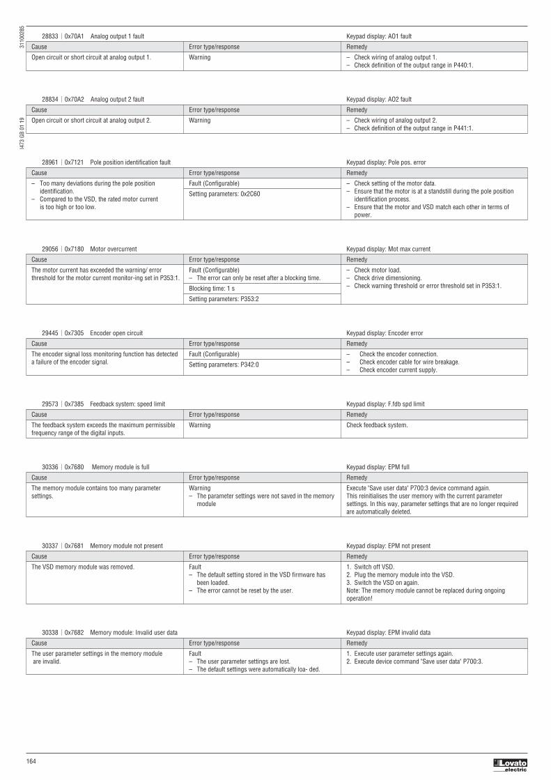
I473
GB
01 1
9
3
1100
285
164
28833 0x70A1 Analog output 1 fault Keypad display: AO1 fault
Cause Error type/response Remedy
Open circuit or short circuit at analog output 1. Warning – Check wiring of analog output 1. – Check definition of the output range in P440:1.
28834 0x70A2 Analog output 2 fault Keypad display: AO2 fault
Cause Error type/response Remedy
Open circuit or short circuit at analog output 2. Warning – Check wiring of analog output 2. – Check definition of the output range in P441:1.
28961 0x7121 Pole position identification fault Keypad display: Pole pos. error
Cause Error type/response Remedy
– Too many deviations during the pole position Fault (Configurable) – Check setting of the motor data. identification. Setting parameters: 0x2C60 – Ensure that the motor is at a standstill during the pole position – Compared to the VSD, the rated motor current identification process. is too high or too low. – Ensure that the motor and VSD match each other in terms of power.
29445 0x7305 Encoder open circuit Keypad display: Encoder error
Cause Error type/response Remedy
The encoder signal loss monitoring function has detected Fault (Configurable) – Check the encoder connection. a failure of the encoder signal. Setting parameters: P342:0 – Check encoder cable for wire breakage. – Check encoder current supply.
29573 0x7385 Feedback system: speed limit Keypad display: F.fdb spd limit
Cause Error type/response Remedy
The feedback system exceeds the maximum permissible Warning Check feedback system. frequency range of the digital inputs.
30336 0x7680 Memory module is full Keypad display: EPM full
Cause Error type/response Remedy
The memory module contains too many parameter Warning Execute "Save user data" P700:3 device command again. settings. – The parameter settings were not saved in the memory This reinitialises the user memory with the current parameter module settings. In this way, parameter settings that are no longer required are automatically deleted.
30337 0x7681 Memory module not present Keypad display: EPM not present
Cause Error type/response Remedy
The VSD memory module was removed. Fault 1. Switch off VSD. – The default setting stored in the VSD firmware has 2. Plug the memory module into the VSD. been loaded. 3. Switch the VSD on again. – The error cannot be reset by the user. Note: The memory module cannot be replaced during ongoing operation!
30338 0x7682 Memory module: Invalid user data Keypad display: EPM invalid data
Cause Error type/response Remedy
The user parameter settings in the memory module Fault 1. Execute user parameter settings again. are invalid. – The user parameter settings are lost. 2. Execute device command "Save user data" P700:3. – The default settings were automatically loa- ded.
29056 0x7180 Motor overcurrent Keypad display: Mot max current
Cause Error type/response Remedy
The motor current has exceeded the warning/ error Fault (Configurable) – Check motor load. threshold for the motor current monitor-ing set in P353:1. – The error can only be reset after a blocking time. – Check drive dimensioning.
Blocking time: 1 s – Check warning threshold or error threshold set in P353:1.
Setting parameters: P353:2

I473
GB
01 1
9
3
1100
285
165
30340 0x7684 Data not compl. saved before powerdown Keypad display: Save incomplete
Cause Error type/response Remedy
Saving of the parameter settings was interrupted by Warning 1. Check user parameter settings. (The loaded backup is an older an unexpected disconnection. – The user parameter settings were not fully saved. version.) been loaded. 2. If required, repeat the changes made last. – At the next switch-on, the data stored are copied to 3. Execute device command "Save user data" P700:3. the user memory.
30342 0x7686 Internal communication error Keypad display: Int. Comm.Err.
Cause Error type/response Remedy
Communication between the power unit and the control Fault 1. Switch off VSD. unit is faulty. 2. Install control unit correctly on power unit. 3. Switch the VSD on again.
30345 0x7689 Memory module: invalid OEM data Keypad display: OEM data invalid
Cause Error type/response Remedy
The OEM memory contains invalid parameter settings Warning – Execute device command "Save OEM data" P700:6. or is empty. – The user parameter settings were automatically loaded. – Thus, the user parameter settings get lost!
30346 0x768A Memory module: wrong type Keypad display: Wrong EPM
Cause Error type/response Remedy
The memory module connected is not supported by the Fault 1. Switch off VSD. VSD. – The default setting stored in the VSD firmware has 2. Replace plugged-in memory module by a memory module that been loaded. matches the VSD. – The error cannot be reset by the user. 3. Switch the VSD on again.
30352 0x7690 EPM firmware version incompatible Keypad display: EPM-FW incomp.
Cause Error type/response Remedy
The parameter settings saved in the memory module are Fault 1. Execute device command "Load default set-tings" P700:1. incompatible with the firmware ver- sion. – The data have been loaded into the RAM memory, 2. Execute "Save user data" P700:3 or "Save OEM data" P700:6 device but they are incompatible. command.
30353 0x7691 EPM data: firmware type incompatible Keypad display: EPM: FW incomp.
Cause Error type/response Remedy
The parameter settings saved in the memory module are Fault 1. Execute device command "Load default set-tings" P700:1. incompatible with the firmware type. – The data have been loaded into the RAM memory, 2. Execute "Save user data" P700:3 or "Save OEM data" P700:6 Example: Memory module of an VSD with an but they are incompatible. device command. application IO is used in an VSD with a standard IO.
30354 0x7692 EPM data: new firmware type detected Keypad display: UserCU not match
Cause Error type/response Remedy
The parameter settings saved in the memory module do Fault 1. Check parameter settings. not match the VSD hardware. – The data have been loaded into the RAM memory 2. Reset error. without being modified, and they are compatible. 3. Execute "Save user data" P700:3 or "Save OEM data" P700:6 device – The settings loaded must be accepted by the user command. (see remedy).
30355 0x7693 EPM data: PU size incompatible Keypad display: EPM PU size inco
Cause Error type/response Remedy
The parameter settings saved in the memory module are Fault 1. Execute device command "Load default settings" P700:1. incompatible with the VSD. – The data have been loaded into the RAM memory, 2. Execute "Save user data" P700:3 or "Save OEM data" P700:6 device but they are incompatible. command.
30356 0x7694 EPM data: new PU size detected Keypad display: EPM new PU size
Cause Error type/response Remedy
The parameter settings saved in the memory module Fault 1. Check parameter settings. comply with a different hardware. – The data have been loaded into the RAM memory 2. Reset error. Example: Memory module of an VSD with a power without being modified, and they are compatible. 3. Execute "Save user data" P700:3 or "Save OEM data" P700:6 device of 3 kW is used in an VSD with a power of 18.5 kW. – The settings loaded must be accepted by the user command. (see remedy).

I473
GB
01 1
9
3
1100
285
166
30357 0x7695 Invalid parameter changeover configuration Keypad display: InvalidChgovrCfg
Cause Error type/response Remedy
One or more parameters can no longer be used for the Warning 1. Check error message for parameter change-over in P756:1. "Parameter change-over" function. – The parameter change-over function is deactivated. 2. Correct the list entry shown in P756:2.
30358 0x7696 EPM data: unknown parameter found Keypad display: Unkn. Par in EPM
Cause Error type/response Remedy
The memory module contains parameter set- tings for Information Execute the "Save user data" P700:3 device command. one or several parameters that are not known to the This reinitialises the user memory with the current parameter settings. VSD. In this way, parameter settings that are no longer required are automatically deleted.
30359 0x7697 Parameter changes lost Keypad display: Parameter loss
Cause Error type/response Remedy
A voltage failure has occurred and changed parameter Fault 1. Execute parameter settings again. settings that had not been saved yet were available. – The parameter settings changed have been lost. 2. Execute device command "Save user data" P700:3.
33042 0x8112 Network: timeout explicit message Keypad display: TO expl. ms
Cause Error type/response Remedy
– Within the time-out period for explicit messages, Warning (Configurable) – Check cables and terminals. which has been parameterised by the scanner, Setting parameters: P515:6. – Plug network cables into the Ethernet port. no "explicit message" was received. – Check the requested package interval (RPI) of the explicit – The connection to the scanner has been interrupted. connection. – Failure of an explicit connection. – Increase time limit for explicit messages in the scanner.
33154 0x8182 CAN: bus off Keypad display: CAN bus off
Cause Error type/response Remedy
Too many faulty frames have been received. Trouble (Configurable) – Check wiring of the network. – Defective cable (e. g. loose contact). – Change to the "Bus-Off" communication status. – Check bus terminating resistor. – Two nodes with the same node address. Setting parameters: 0x2857:010 – Set the identical baud rate for each node of the network. – Assign a unique node address to each node of the network. – Eliminate EMC interferences.
33155 0x8183 CAN: warning Keypad display: CAN bus warning
Cause Error type/response Remedy
Too many faulty frames have been received. Warning (Configurable) – Check wiring of the network. – Defective cable (e. g. loose contact). Setting parameters: 0x2857:011 – Check bus terminating resistor. – Two nodes with the same node address. – Set the identical baud rate for each node of the network. – Assign a unique node address to each node of the network. – Eliminate EMC interferences.
33156 0x8184 CAN: heartbeat time-out consumer 1 Keypad display: CAN heartb. C1
Cause Error type/response Remedy
Within the heartbeat time P520:1, no heartbeat telegram Fault (Configurable) – Check communication with the heartbeat producer. was received by node 1 to be monitored. Setting parameters: 0x2857:005 – Reactivate heartbeat producer.
33157 0x8185 CAN: heartbeat time-out consumer 2 Keypad display: CAN heartb. C2
Cause Error type/response Remedy
Within the heartbeat time P520:2, no heartbeat telegram Fault (Configurable) – Check communication with the heartbeat producer. was received by node 2 to be monitored. Setting parameters: 0x2857:006 – Reactivate heartbeat producer.
33158 0x8186 CAN: heartbeat time-out consumer 3 Keypad display: CAN heartb. C3
Cause Error type/response Remedy
Within the heartbeat time P520:3, no heartbeat telegram Fault (Configurable) – Check communication with the heartbeat producer. was received by node 3 to be monitored. Setting parameters: 0x2857:007 – Reactivate heartbeat producer.
33159 0x8187 CAN: heartbeat time-out consumer 4 Keypad display: CAN heartb. C4
Cause Error type/response Remedy
Within the heartbeat time P520:4, no heartbeat telegram Fault (Configurable) – Check communication with the heartbeat producer. was received by node 4 to be monitored. Setting parameters: 0x2857:008 – Reactivate heartbeat producer.

I473
GB
01 1
9
3
1100
285
167
33168 0x8190 Network: watchdog timeout Keypad display: Watchdog timeout
Cause Error type/response Remedy
Time-out during cyclic data reception, e.g. due to an Trouble (Configurable) • Check wiring of the network. interrupted communication link to the master or missing Setting parameters: • Eliminate EMC interferences. cyclic data. P515:1 (PROFIBUS, EtherCAT, PROFINET)
33169 0x8191 Network: disruption of cyclic data exchange Keypad display: Cycl data error
Cause Error type/response Remedy
The communication partner has interrupted the cyclic No response (Configurable) – Check wiring of the network. data exchange. Setting parameters: P515:2 – The slave must receive new parameterisation and configuration files by the master, in order to be able to exchange data again.
33170 0x8192 Network: initialisation error Keypad display: Net. Init. error
Cause Error type/response Remedy
The initialisation of the communication stack has been Trouble (Configurable) Check master/slave configuration and restart the devices. interrupted due to an incorrect address setting or Setting parameters: communication configuration. 515:4 (PROFIBUS, EtherCAT, PROFINET)
33171 0x8193 Network: invalid cyclic process data Keypad display: Inv. cyclic data
Cause Error type/response Remedy
The cyclic process data received are invalid. Trouble (Configurable) Check cyclic process data sent by the master. Setting parameters: 515:5 (PROFIBUS, EtherCAT, PROFINET)
33185 0x81A1 Modbus: network time-out Keypad display: Modbus time-out
Cause Error type/response Remedy
No valid messages have been received via the Modbus Fault (Configurable) – Check communication with the master. for a longer time than the time-out time set in P515:2. Setting parameters: P515:1 – Check wiring. – Check bus termination.
33186 0x81A2 Modbus: incorrect request by master Keypad display: Modbus request
Cause Error type/response Remedy
The request by the master is invalid, e. g. invalid CRC Warning Check request by the master: checksum, non-supported function code, or impermissible – The VSD (slave) responds to the master with an – Value in the valid range? data access. error code: – Function code valid? 0x01 = invalid function code – No impermissible write access? (e. g. with regard to read-only 0x02 = invalid data address parameters) 0x03 = invalid data value 0x04 = slave device failure
33200 0x81B0 Network communication faulty Keypad display: Comm. faulty
Cause Error type/response Remedy
In case of the Ethernet communication interface, Trouble – Switch VSD off and on again. an internal software error has occurred. – In the event of a power failure during a firmware download, it is required to reload the firmware via the USB module and then restart the VSD.
33414 0x8286 Network: PDO mapping error Keypad display: PDO map error
Cause Error type/response Remedy
– Invalid PDO assignment by the master. Trouble (Configurable) Check data mapping in the master and slave. – Internal PDO assignment was changed and does not Setting parameters: comply with the configuration available in the master. P515:3 (PROFIBUS, EtherCAT, PROFINET)
33425 0x8291 CAN: RPDO1 time-out Keypad display: Timeout RPDO1
Cause Error type/response Remedy
RPDO1 was not received within the time-out period set Fault (Configurable) – Eliminate EMC interferences. in P540:5 or with the sync configured. Setting parameters: 0x2857:001 – Check bus load.

I473
GB
01 1
9
3
1100
285
168
33426 0x8292 CAN: RPDO2 time-out Keypad display: Timeout RPDO2
Cause Error type/response Remedy
RPDO2 was not received within the time-out period set Fault (Configurable) – Eliminate EMC interferences. in P541:5 or with the sync configured. Setting parameters: 0x2857:002 – Check bus load.
33427 0x8293 CAN: RPDO3 time-out Keypad display: Timeout RPDO3
Cause Error type/response Remedy
RPDO3 was not received within the time-out period set Fault (Configurable) – Eliminate EMC interferences. in P542:5 or with the sync configured. Setting parameters: 0x2857:003 – Check bus load.
33553 0x8311 Torque limit reached Keypad display: Torque limit
Cause Error type/response Remedy
Motor has reached the torque limit: No response (Configurable) – Observe load requirements. – P337:3: Actual positive torque limit Setting parameters: P329:1 – Reduce motor load. – P337:4: Actual negative torque limit – Check set torque limits and sources for the torque limits.
33664 0x8380 Function not allowed in selected operating mode Keypad display: Func. n. allowed
Cause Error type/response Remedy
The selected function is not permissible in the chosen Warning – Note: selection of torque mode [-1] in P301:0 with incompatible operating mode. motor control in P300:0. – Selection of torque mode [-1] in P301:0 – Check settings of operation modes. with incompatible motor control in P300:0. – Selection of invalid drive mode [0] in P301:0.
36992 0x9080 Keypad removed Keypad display: Keypad removed
Cause Error type/response Remedy
The keypad was removed while the keypad control was Fault – Plug keypad back in or activate another control source. activated.
65282 0xFF02 Brake resistor: overload fault Keypad display: BrkResistor OL.F
Cause Error type/response Remedy
The calculated thermal load of the brake resistor has Fault (Configurable) – Check drive dimensioning. reached the error threshold set in P707:9. – The error can only be reset after a blocking time. – Check settings for the brake energy manage- ment.
The regenerative energy is too high. Blocking time: 5 s Note: The error status will be reset if the ther- mal load falls below
Setting parameters: P707:11 the error threshold - 20 %.
65285 0xFF05 Safe Torque Off is locked Keypad display: STO locked
Cause Error type/response Remedy
The safety module or safety circuit of the device was Fault Hardware error: it is necessary to contact the manufacturer since detected as being defective. – The VSD is inhibited immediately. the device must be replaced. The motor becomes torqueless (coasts). – The error can only be reset by mains switching.
65286 0xFF06 Motor overspeed Keypad display: Motor overspeed
Cause Error type/response Remedy
The motor speed has reached the error threshold Fault (Configurable) Check application. for overspeed set in P35:1. – The error can only be reset after a blocking time.
Blocking time: 1 s
Setting parameters: P350:2
65289 0xFF09 Motor phase missing Keypad display: Mot.Phase miss.
Cause Error type/response Remedy
A failure of several motor phases has been detected. No response (Configurable) • Check wiring between VSD and motor. – The error can only be reset after a blocking time. • In case of a false tripping, adapt the settings for the motor phase
Blocking time: 2 s failure detection.
Setting parameters: P310:1

I473
GB
01 1
9
3
1100
285
169
65290 0xFF0A Motor phase failure phase U Keypad display: Phase U failure
Cause Error type/response Remedy
A failure of the motor phase U has been detected. No response (Configurable) • Check wiring between VSD and motor. – The error can only be reset after a blocking time. • In case of a false tripping, adapt the settings for the motor phase
Blocking time: 2 s failure detection.
Setting parameters: P310:1
65291 0xFF0B Motor phase failure phase V Keypad display: Phase V failure
Cause Error type/response Remedy
A failure of the motor phase V has been detected. No response (Configurable) • Check wiring between VSD and motor. – The error can only be reset after a blocking time. • In case of a false tripping, adapt the settings for the motor phase
Blocking time: 2 s failure detection.
Setting parameters: P310:1
65292 0xFF0C Motor phase failure phase W Keypad display: Phase W failure
Cause Error type/response Remedy
A failure of the motor phase W has been detected. No response (Configurable) • Check wiring between VSD and motor. – The error can only be reset after a blocking time. • In case of a false tripping, adapt the settings for the motor phase
Blocking time: 2 s failure detection.
Setting parameters: P310:1
65305 0xFF19 Motor parameter identification fault Keypad display: Motor ID fault
Cause Error type/response Remedy
During the automatic identification of the motor, Fault – Set motor data so that they comply with the data on the motor an error has occurred. nameplate. – Check wiring of the motor.
65311 0xFF1F FMF Error Keypad display: FMF Error
Cause Error type/response Remedy
Configuration or runtime error Fault – Check configuration – Check FMF error code 0x4050:002 to deter- mine the error cause.
65335 0xFF37 Automatic start disabled Keypad display: Auto start disab
Cause Error type/response Remedy
At mains connection, a start command was already Fault Deactivate starting command and reset error. available and the automatic start at power-up is set in P203:2 to "Off [0]".
65334 0xFF36 Brake resistor: overload warning Keypad display: BrkResistor OL.W
Cause Error type/response Remedy
The calculated thermal load of the brake resistor has Warning (Configurable) • Check drive dimensioning. reached the warning threshold set in P707:8. Setting parameters: P707:10 • Check settings for the brake energy management. The regenerative energy is too high. Note: The warning status is reset if the thermal load falls below the warning threshold of -20%.
65336 0xFF38 Load loss detected Keypad display: Load loss
Cause Error type/response Remedy
In a running motor, the motor load (current) is monitored. No response (Configurable) Check utilisation When the motor load falls below the threshold value Setting parameters: P710:3 specified in Load loss detection: threshold P710:1 for the period of time specified in Load loss detection:
delay time (P710:2), load loss protection is triggered.
65337 0xFF39 Motor overload Keypad display: Motor overload
Cause Error type/response Remedy
If the apparent motor current exceeds a defined threshold No response (Configurable) Check the motor load. value 0x4007:002 for a certain amount of time Setting parameters: 0x4007:003 0x4007:001, heavy duty moni- toring is triggered.

I473
GB
01 1
9
3
1100
285
170
65366 0xFF56 Maximum motor frequency reached Keypad display: Max. motor freq.
Cause Error type/response Remedy
– The maximum motor speed set in P322:0 is active. Warning Check application. – The maximum output frequency of the VSD has been reached.
65393 0xFF71 Wrong password Keypad display: Wrong password
Cause Error type/response Remedy
A wrong password has been entered several times. Warning Wait until the blocking time has elapsed and then enter the correct – The blocking time for entering a password is more password. than 10 seconds. (The blocking time is doubled every time an incorrect password is entered.) – No password can be entered as long as the blocking time is active.
65394 0xFF72 Warning Keypad display: Warning
Cause Error type/response Remedy
VSD is not compatible with the Controller/PLC Warning Use corresponding (compatible) OEM components. (brand protection). • No response from the VSD. – The Controller has not written a deactivation password • The decision on whether the machine will be in the parameter yet. commissioned or not is made by the Controller. – The deactivation password written by the Controller is incorrect.
65395 0xFF73 Fatal Error Keypad display: Fatal Error
Cause Error type/response Remedy
Error when reading the data from the control unit. Fault – Switch VSD off and on again. – Operation of the VSD is not possible. – If the error occurs again, the manufacturer must be contacted, since the control unit or the device has to be replaced.
65396 0xFF74 Power unit fatal error Keypad display: PU fatal error
Cause Error type/response Remedy
Error when reading the data from the power unit. Fault – Switch VSD off and on again. – Operation of the VSD is not possible. – If the error occurs again, the manufacturer must be contacted, since the control unit or the device has to be replaced.
65413 0xFF85 Keypad full control active Keypad display: Keypad full ctrl
Cause Error type/response Remedy
If the "Keypad Full Control" control mode is active. Warning Clicking the CTRL keypad key stops the control mode again. – Both the activity of controlling and the setpoint selection are carried out via the key-pad.

I473
GB
01 1
9
3
1100
285
171
7 UPDATE DEVICE FIRMWARE
The device firmware is continuously improved by the manufacturer. New firmware versions contain error corrections, function extensions and simplify the handling.A new firmware is always compatible with the older version:– A device with updated firmware and unchanged parameter settings shows the same behaviour as before.– Parameter settings must only be adapted if new functions are used.
RequiremetsTo update the firmware of VLB3 is necessary:1. The optional USB module, type code VLBXC022. A USB 2.0 cable (A plug on Micro-B plug).3. The software VLBXSW, freely downloadable from the website www.LovatoElectric.com in the section Downloads > Software & upgrades > Variable speed drives.
Notes– The voltage supply of the VLBXC02 module takes place via the USB connection.– The communication must not be interrupted during the firmware download.– The firmware update procedure can be done on VLB3 variable speed drivers with firmware revision >=4.1.
DetailsTogether with the VLBXSW software, the following tools are installed as well:
Procedure for the firmware update1. Download the file “Packages for VLBXSW” from the Lovato Electric website, section Downloads > Software & upgrades > Variable speed drives and extract the content in a folder on your PC.
Tool Brief description
VLBXSW00 Enables the installation of the following packages (“Packages for VLBXSW”, downloadable from Lovato Electric website): (package manager) – drivers for VLBXSW01 software – firmware files for variable speed drives.
VLBXSW01 Software for the parameter settings and monitoring of the variable speed drive. (configuration software)
VLBXSW02 Enables the update of the firmware for variable speed drives. (firmware loader) – The update can be made by the mechanical engineer or the end user depending on the access protection set for the device.
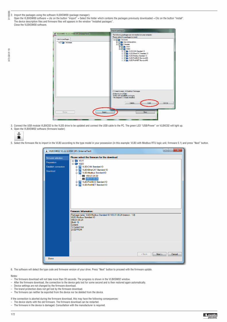
I473
GB
01 1
9
3
1100
285
172
2. Import the packages using the software VLBXSW00 (package manager): Open the VLBXSW00 software → clic on the button “Import” → Select the folder which contains the packages previously downloaded → Clic on the button “Install”. The device description files and firmware files will appears in the window “Installed packages”. Close the VLBXSW00 software.
3. Connect the USB module VLBXC02 to the VLB3 drive to be updated and connect the USB cable to the PC. The green LED “USB/Power” on VLBXC02 will light up.4. Open the VLBXSW02 software (firmware loader)
5. Select the firmware file to import in the VLB3 according to the type model in your possession (in this example: VLB3 with Modbus RTU logic unit, firmware 5.1) and press “Next” button.
6. The software will detect the type code and firmware version of your drive. Press “Next” button to proceed with the firmware update.
Notes:– The firmware download will not take more than 20 seconds. The progress is shown in the VLBXSW02 window.– After the firmware download, the connection to the device gets lost for some second and is then restored again automatically.– Device settings are not changed by the firmware download.– The brand protection does not get lost by the firmware download.– The firmware can neither be exported from the device nor be deleted from the device.
If the connection is aborted during the firmware download, this may have the following consequences:– The device starts with the old firmware. The firmware download can be restarted.– The firmware in the device is damaged. Consultation with the manufacturer is required.

I473
GB
01 1
9
3
1100
285
173
8 Safe Torque Off (STO) moduleThe motor cannot generate torque and movements of the drive.
DANGER!Automatic restart if the request of the safety function is deactivated.Possible consequences: Death or severe injuriesYou must provide external measures according to EN ISO 13849−1 which ensure that the drive only restarts after a confirmation.
DANGER!The power supply is not safely disconnected.Possible consequences: Death or serious injury due to electrical voltage.Turn off the power supply.
PreconditionsThe VLB3 variable speed drive must be equipped with the optional STO module, type code VLBXSM.
DetailsSafe disconnection of the drive1. A safety sensor requests the safety function.2. The pulse width modulation is safely switched off by the safety unit.The VSD switches to the STO active device status (0x6041, Bit15 = 0).The power drivers do not generate a rotating field anymore.The motor is safely switched to torqueless operation (STO).
The functional principle depicted applies to Basic Safety (STO) and Extended Safety. The terminals shown apply to Basic Safety.i
Functional principle of safety technology for Extended Safety and Basic Safety (STO)
X1 Control terminals of the safety unitSU Basic Safety (STO) or Extended SafetyµC MicrocontrollerPWM Pulse width modulationM Motor
Functional description
Functional sequence and error response have no adjustable parameters.
Truth table
i
If the GS connection is interrupted or in case of a short circuit/short circuit of GS to SIA/SIB, STO is active.i
Safe input / channel Drive Drive status word CiA402 status word
SIA SIB Device status Bit 55 Bit 155 Object 0x6041, bit 15
LOW LOW STO active 1 1 0
LOW HIGH Impermissible state 1 0 0
HIGH LOW Impermissible state 1 0 0
HIGH HIGH Drive enabled 0 0 1

I473
GB
01 1
9
3
1100
285
174
9 MAINTENANCE
The VLB3 VSD does not require any maintenance if the prescribed operating conditions are observed.
9.1 ROUTINE INSPECTIONS
NOTICE!It is a good practice to check the VSD during a routine inspection of the drive system: Remove dust from VSD housing if necessary. Check that ventilation slots are not covered or obstructed. Check the condition and tightness of the electric connections. The integrity of all earth / ground connections should be periodically checked.
DANGER!Dangerous electrical voltagePossible death or severe injuries due to electrical shock. All inspection works on the VSD must only be carried out in the deenergised state. After switching off the mains voltage, the capacitors in the VSD can still be charged. Observe the waiting time on the VSD label before commencing work.
9.2 PRODUCT SUPPORTLOVATO Electric S.p.A.Via Don E. Mazza, 1224020 Gorle, Bergamo, Italy
Phone: +39 0354282422Fax: +39 0354282295Email: [email protected]
10 DECOMMISSIONING
10.1 SAFETY INSTRUCTIONS
WARNING!Dangerous electrical voltageAn electrical shock can cause death or severe personal injury. Apply lockout/tagout procedures for decommissioning. Connect/disconnect all pluggable VSD connections only in deenergised condition! Only remove the VSD from the installation in completely deenergised state.
10.2 REMOVAL AND DISPOSALRecycle metal and plastic materials of the VSD. Ensure professional disposal of assembled PCBs.
Observe all applicable national regulations for the disposal of waste electronic equipment.
i