Embed Size (px)
Citation preview

GC Cryo-TrapModel 961for Liquid Nitrogen Cooling
Scientific Instrument Services, Inc.1027 Old York RoadRingoes, NJ 08551
Phone (908) 788-5550
Part #951001Mrevised 10/ /98

Notice
The information in this document is subject to change without notice.
Scientific Instrument Services (S.I.S.) makes no warranty of any kind with regard to the material containedin this manual, including, but not limited to, the implied warranties of merchantability and fitness of theequipment and techniques therein described for a particular purpose.
S.I.S. shall not be liable for errors contained herein or for incidental or consequential damages in connectionwith the furnishing, operation, performance or use of the GC Cryo-Trap described in this manual.
S.I.S. assumes no responsibility for the use or reliability of equipment that is not furnished by S.I.S.
The warranty of the GC Cryo-Trap is for 90 days and includes all parts and labor. All service and repairincluding warranty repairs will be performed at the repair facilities of Scientific Instrument Services inRingoes, NJ.
GC Cryo-Trap Installation Packages
Depending on the make and model of your Gas Chromatograph, one of the following installation kitsmust be ordered. No drilling or additional hardware is required. Multiple mounting brackets may be orderedfor installation in more than one GC. Kits for other makes and models will be added as required, so give usa call if you wish to use a GC not listed below.
Cryo-Trap Installation Kits
Part # Description900110 Cryo-Trap Installation Kit for Hewlett-Packard 5890A GC900111 Cryo-Trap Installation Kit for Hewlett-Packard 5890 Series I and II900112 Cryo-Trap Installation Kit for Hewlett-Packard 6890 GC900113 Cryo-Trap Installation Kit for Hewlett-Packard 5880 GC900120 Cryo-Trap Installation Kit for Varian 3400/3600/3700 GC with
1075/ 1040/ 1041 and 1077 Injectors900121 Cryo-Trap Installation Kit for Varian 3600 GC with 1078 Injector900122 Cryo-Trap Installation Kit for Varian 3800 GC900130 Cryo-Trap Installation Kit for Shimadzu GC-9A900140 Cryo-Trap Installation Kit for Finnigan GCQ GC/MS System
S.I.S. Short Path Thermal Desorption Program Chip
When the GC Cryo-Trap is used with the S.I.S. Model TD-2 Short Path Thermal Desorption system,the TD-2 program chip should be ordered. This upgrade allows the TD-2 controller to automatically controlthe switching of the GC Cryo-Trap from cooling to heating mode when the thermal desorption process iscomplete. This chip is for use ONLY with the Model TD-2 Short Path Thermal Desorption System. No chipis needed for use with the Model TD3 Short Path Thermal Desorption System.
951C Cryo-Trap IC Chip upgrade for SIS Model TD-2 Short Path Thermal Desorption System
2

Safety Information
WARNING Connecting the GC Cryo-Trap to a power source which is not equipped with a protective earth ground contact creates a shock hazard for the operator and can damage the instrument.
WARNING Make sure that only fuses with the required current rating and of the specified type are used for replacement. The use of incorrect or make shift fuses or the short-circuiting of the fuse creates a shock hazard for the operator and can damage the instrument.
WARNING Any adjustment, maintenance or repair of the opened instrument while it is connected to a power source should be avoided if possible and, if required, should be carried out only by trained persons who are aware of the hazards involved.
WARNING Hazardous Temperatures - Keep hands and fingers from the GC Cryo-Trap whenit is operating. The GC Cryo-Trap is subjected to both heating and cooling temperatures (-180° C to 400° C) which can cause severe burns.
WARNING The GC Cryo-Trap Model 961 is designed for cooling using liquid nitrogen only.Do NOT use CO2 or any other cooling gas.
WARNING Do not leave the Cryo-Trap in either the heated or cooled position unattended overnight. The GC Cryo-Trap will both heat and cool quickly to its final temperature. Therefore, in order to prolong the life of the Cryo-Trap, it should be turned off when not actively being utilized for analysis.
WARNING Due to the complexity of the internal wiring of the GC Cryo-Trap, disassembly and repair should not be attempted by the user. Disassembly will result in furtherdamage to the Cryo-Trap and will void all warranties.
WARNING Avoid using excessive heat in the Cryo-Trap to remove the trapped volatiles from the guard column. The Cryo-Trap heating temperature should not exceed the maximum rated temperature of the guard column or decomposition of the liquid phase will occur. This will readily be apparent with the appearance of siloxane peaks ( M/e ions at 207, 281, 267, 355) in the chromatogram.
ServiceAll service will be performed at the repair facilities of Scientific Instrument Services in Ringoes, NJ. If service is required, both the Cryo-Trap and its controller should be sent to the following address for repair.
Scientific Instrument Services, Inc.1027 Old York RdRingoes, NJ 08551Attn: Repair Dept.
3
General Information
Features:
• Dual Programmable Cryo-Cooling and Heating Cycles• Trap Compounds in the GC Oven at the Head of the GC Column• Trap is Positioned Directly under GC Injection Port • Low Dead Volume Cryo-Trapping System• Trap Volatiles down to -180°C using Liquid Nitrogen• Reduce Nitrogen usage by >90% as Compared to Whole Oven Cooling• Remote Input Connector for Cryo-Cooling to Heating Cycle Switching Via GC, Desorption
System or Manual Control• Rapid Heating up to 400°C at > 400° per minute• Remote Start Output Signal for Starting GC, MS or recorder
Applications
The GC Cryo-Trap is designed for the trapping of volatiles and semi-volatiles injected into the GC injection port via all of the following techniques:
• Thermal Desorption Sample Trapping• Purge and Trap Systems• GC Head Space Analysis• GC Syringe Injections• GC Pyrolysis• Multidimensional GC System Development
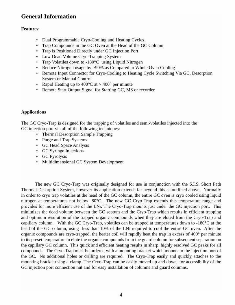
The new GC Cryo-Trap was originally designed for use in conjunction with the S.I.S. Short PathThermal Desorption System, however its application extends far beyond this as outlined above. Normallyin order to cryo trap volatiles at the head of the GC column, the entire GC oven is cryo cooled using liquidnitrogen at temperatures not below -80°C. The new GC Cryo-Trap extends this temperature range and provides for more efficient use of the LN2. The Cryo-Trap mounts just under the GC injection port. This minimizes the dead volume between the GC septum and the Cryo-Trap which results in efficient trappingand optimum resolution of the trapped organic compounds when they are eluted from the Cryo-Trap and capillary column. With the GC Cryo-Trap, volatiles can be trapped at temperatures down to -180°C at thehead of the GC column, using less than 10% of the LN2 required to cool the entire GC oven. After the organic compounds are cryo-trapped, the heater coil will rapidly heat the trap in excess of 400° per minuteto its preset temperature to elute the organic compounds from the guard column for subsequent separation onthe capillary GC column. This quick and efficient heating results in sharp, highly resolved GC peaks for allcompounds. The Cryo-Trap must be ordered with a mounting bracket which mounts to the injection port ofthe GC. No additional holes or drilling are required. The Cryo-Trap easily and quickly attaches to themounting bracket using a clamp. The Cryo-Trap can be easily moved up and down for accessibility of theGC injection port connection nut and for easy installation of columns and guard columns.
4
Description of System
The Cryo-Trap consists of a smallheating/cooling chamber which is 3/4" indiameter and 5" long (Figure # 1). In thecenter of the chamber is a small stainlesssteel capillary through which the capillarycolumn freely passes. Capillary columnsup to megabore (0.53 mm I.D.) diameterscan be used. Around the stainless steelcapillary tube a heating coil is wound toprovide for the rapid heating of the capillary tube. A thermocouple providesaccurate measurement of both the coolingand heating temperatures and provides thesignal for the accurate regulation of boththe heating and cooling of the Cryo-Trap bythe dual range temperature controller. Theliquid nitrogen for cooling is released intothe top connector in the Cryo-Trap, while thebottom connector serves as an outlet whichcan either be vented into the GC or a tubecan be attached to vent the expired LN2
external to the GC oven.
The control of the Cryo-Trap is provided via an independent Cryo-TrapController provided with the System .Both the Cryo Cooling and Heating temperatures are set via the digital temperature controller. The system canbe used either manually to switchbetween cooling and heating or can beoperated automatically via an input signal from a controlling device such asthe S.I.S. Short Path Thermal DesorptionSystem (Fig. 2) or other GC input. Thisinput switches the system from the normally cooling position to the heatingcycle. Cryo-Cooling temperatures downto -180°C can be set via the controllerusing liquid nitrogen as the cooling gas.Heating temperatures, to remove thetrapped volatiles from the trap, of up to400°C are achievable at a ramp rate ofabout 600° per minute. This provides morethan sufficient heating to release bothvolatiles and semi-volatiles from the trap efficiently with sharp and narrow peak shapes. Use care not toexceed the maximum rated temperature limit of the guard column or column bleed peaks will appear in yourchromatogram.
5
OFF
AUTOHEAT
COOL
Power
-60°CSET * 1 2
GC CRYO-TRAPScientific Instrument Services
Dual Temperature Rangeemperature Controller
GCCryo-Trap
Cooling Gas In
Heating Coil
Thermocouple
Cryo-Trap Cooling& Heating Chamber
Cooling Gas Exhaust
GC Capillary Columnor Megabore Guard Column
OFF
AUTOHEAT
COOL
Power
-60°CSET * 1 2
GC CRYO-TRAPScientific Instrument Services
Figure 2 GC Cryo-Trap Mounted in GC Oven
Power
-60 C1 2*SET
GC CRYO-TRAPScientific Instrument Services
AUTOOFF HEAT
CO
Desorb Cryo-TrapController
Thermal Desorption Unit
GC Injection Port
Megabore Guard Column
To GC Detector or MS
Cooling Gas
Heating Coil
CapillaryUnion
HPMounting Bracket
Thermocouple
GC Capillary Column
GC Cryo-Trap
Short Path Thermal Desorption System
Figure 1 GC Cryo-Trap

The Cryo-Trap System comes complete with Cryo-Trap, liquid nitrogen valve, and Dual TemperatureController. An installation kit for your make and model of GC must be ordered separately. Power requirements are 110 VAC, 3 amp max. An external supply of liquid nitrogen is required for the coolingoperation.
As described above, the systemwas originally designed to be used withthe S.I.S. Short Path ThermalDesorption System TD2 (Fig. 3). A newprogram chip can be installed in theTD2 controller which permits theremote 2 connector on the Short PathThermal Desorption System to be usedfor the automatic control of the Cryo-Trap. This will automatically switch theCryo-Trap to begin the cooling cyclewhen the initial gas purge step is begunon the Thermal Desorption System.When the desorption process is complete, the Thermal Desorption system will activate the Cryo-Trap toswitch from the cooling cycle to theheating cycle and begin the GC oventemperature program. The new ModelTD3 Short Path Thermal Desorption hasall the Cryo-Trap control circuitry builtin and does not require any additional program chips. Call SIS technical staff for more information.
Other applications of the Cryo-Trap include the trapping of volatiles from purge and trap systems,trapping of volatiles from GC head space systems, standard GC injection trapping and pyrolysis system trapping. This technique will permit the injection of larger samples over a longer period of time and willimprove peak shapes, especially of theearly fast eluting compounds. TheCryo-Trap could also be developed intoa system for Multidimensional GCanalysis, although to date this has notbeen done at S.I.S.
The chart at the right (Fig. 4)shows the usefulness of the GC Cryo-Trap for the trapping of straight chainhydrocarbons C-3 through C-9. For thisanalysis a Guard column was usedinside the Cryo-Trap which consisted ofa DB5 column, 0.53 mm I.D. x 150 mmlong x 1.5 u film thickness. At the exitof the Cryo-Trap a capillary union wasused to attach the guard column to aDB-5-MS capillary column, 0.25 mm x60 meter x 0.25 u film thickness. By
6
200
Power
-60 C1 2*SET
GC CRYO-TRAPScientific Instrument Services
AUTOOFF HEAT
COOL
Desorb
Mass Spec
Cryo Trap
GC Oven
Cryo-TrapController
Thermal Desorption Unit
CapillaryColumn
Figure 3 Complete GC/MS/TD/Cryo-Trap System
Figure 4 Trapping Efficiency of Hydrocarbons on GC Cryo-Trap as a Function of Trapping Temperature

decreasing the temperature of the Cryo-Trap from room temperature down to -180°C, the efficiency of trapping the volatiles was increased. Normal use of a cryo-cooling GC oven can just barely trap Hexane(melting point -95), however, by using the Cryo-Trap this can be extended down to pentane (Melting point -130)and even ethane when trapping at -180. We have been able to accurately quantify Acetone, ethyl acetate, methylenechloride, and chloroform in pharmaceuticalsusing the Cryo-Trap in conjunction with thedirect thermal extraction technique and theS.I.S. Short Path Thermal Desorption System.(Data available on our website atwww.sisweb.com).
Guard Columns
A wide variety of guard columns canbe used with the Cryo-Trap depending on theusers preference. The purpose of the guardcolumn is to trap the volatiles and semi-volatiles on the surface or on the liquidphase of this section of column inside theCryo-Trap and then to rapidly release these organics when the guard column is heated. Normally the guard column should not extend more than 20 mm beyond the bottom of the Cryo-Trap. A low dead volume connector is used to join the guard column to the GC capillary column (Fig. 2). A comparison of several guardcolumns is shown in Figure 5. This study compares a deactivated fused silica guard column, which trapsvolatiles based strictly on the melting point of the volatiles, to various liquid phase coated guard columns, whichincrease the range of low boilers which are trapped due to the interaction between the volatiles and the liquidphase coating. Thick film liquid phase coatings provide for the optimum retention of the low boilers, however they have a limited temperature range and may not release the higher boiling compounds. For theanalysis of volatiles, the thick film guard columns are normally used. For the analysis of semi-volatiles (suchas the PNA’s) uncoated deactivated fused silica columns are normally used. Megabore guard columns are recommended due to their larger surface area and ability to handle larger samples and samples with higher watercontent. In contrast microbore guard columns would provide for slightly higher resolution but are more susceptible to the formation of ice plugs if the samples contain any appreciable levels of water. Plot guardcolumns can be utilized to trap gases.
For optimum peak resolution, we recommend using a deactivated fused silica guard column. This guardcolumn provides a good surface for cryotrapping compounds with melting points down to the cryo-trap temperature. By using a megabore guard column, the occurrence of water plugs can be minimized in the cryo-trap section of this guard column. The larger internal diameter and surface permits the trapping of samples withhigher moisture content than microbore capillary guard columns.
By using guard columns with liquid phases, compounds with melting points below the cryo-trap temperature can be trapped. The thicker the liquid phase, the better the trapping efficiency. For example by using a 0.53mm I.D. DB-5 Megabore column with a 5.0 u film thickness, compounds with melting points down to -130 (i.e. Pentane)can be trapped at a cryo trap temperature of -70°C. When using these liquid phase coated guard columns, some loss inresolution, especially at the lower end of the chromatogram may be observed, but much lower volatiles will be trappedthan would otherwise be possible. When using these thick film megabore guard columns, make a union to your capillary column as close to the Cryo-Trap module as possible. If this is not done, additional loss in resolution will occursince the guard column will begin to act as the analysis column during temperature programming of the GC oven.
7
Figure 5 Effect of Guard Column on the Trapping Efficiency of Hydrocarbons at -60°C

Site PreparationConnecting Liquid Nitrogen
A low pressure (<50 psi) tank must be utilized to supply nitrogen in liquid phase to the remote liquidnitrogen valve. A minimum 1/4” o.d. stainless steel or copper line should supply the liquid nitrogen from thetank to the valve. The 1/4” copper line supplied with the Cryo-Trap should be used to carry the liquid nitrogen from the valve to the GC Cryo-Trap inside the GC oven. All of these lines and the liquid nitrogenvalve should be insulated if possible. Foam pipe insulation or a similar material can be used to prevent watercondensation and ice build-up. Insulation of the lines will also greatly decrease the time required to cool thelines and valve when the LN2 valve is first opened.
Installation of the GC-Cryotrap on the H.P. 5890 Gas Chromatograph
The GC-Cryotrap consists of three components; the Electronics Console, the Cryo-Trap Module andthe remote LN2 valve. The Electronics Console is designed to sit on top of or in close proximity to the GasChromatograph (Fig. 2 and 3). The Cryotrap Module is designed to be mounted inside the GC oven justunder the front injection port. A mounting bracket is clamped to the bottom of the injection port and the Cryo-Trap is then clamped to the mounting bracket. The only modification to the GC that is required is the removalof the GC injection port cover as explained below. The LN2 valve should be mounted as close as possible tothe entrance of the LN2 line into the GC oven wall. You may wish to cut the 1/4” copper line if it is too long.No additional mounting screws or drilling of holes is required.
8

Installation of the GC Cryo-Trap
Installation of the Cryo-Trap Module on the HP 5890 GC
Step 1
Begin by opening the GC oven door. The mounting bracket is to be mounted just under the injectionport (Figure 6). Initial installation can best be accomplished with the GC column removed. However, installation can be accomplished with the column installed provided that extreme care is taken by the installerto avoid breaking the GC column. First, loosen the 2 screws (Figure 6) and remove the protective coveringfrom beneath the injection port (Figure 7). Install the flat replacement protective cover supplied with the GCCryo-Trap installation package using the same two screws. (Figure 8)
9
Figure 6
Screws
Protectivecovering
Figure 7

Step 2
The Cryo-Trap mounting bracket isdesigned to clamp to the stem of the GCinjection port fitting that attaches to the GCinjection port (Figure 9) using the two hexhead bolts.
Step 3
The Cryo-Trap horizontal positionsare fixed, since the trap is aligned by themounting bracket directly under the GCinjection port. (Figure 9) To adjust the heightof the Cryo-Trap, loosen the hex nut on theCryo-Trap mounting bracket. (Figure 10)The Cryo-Trap can then be positioned up anddown slightly. This will permit the easyinstallation and attachment of the capillarycolumns.
10
Figure 8
Figure 9 Figure 10
InjectionPort System
Cryo-TrapMountingBracket
KnurledAdjustmentNuts
ReplacementProtectiveCover

Step 4
Feed the Electrical lead up behind theCryo-Trap module (Figure 11) and out throughone of the exit ports in the GC oven . A convenientGC oven exit to use is the port for a second GCinjection port. This second GC injection port exitis preferred due to its close proximity to the Cryo-Trap in the GC oven. Carefully move the insulation in this port to one side, or if preferredremove this plug of insulation for the easy passageof the electrical leads. Other exit ports such asspare detector ports could also be used.
Step 5 Next slide the 1/4” x 1.0 meter length of
copper tubing through the same hole that the electrical lead exited from the GC oven (Figure12).Attach the 1/4” nut from this cooling line to the topfitting of the Cryo-Trap module. Keep this copperline and electrical line as short as possible inside theGC oven and position so as not to interfere with theGC column. Use of the exhaust port is optional.
11
Figure 11
Figure 12
Model 951 Installation
Cooling Lineout throughOven Wall
LN2Connection

Step 6
Install the GC capillary column in the GCoven. Depending on whether the capillary columnitself or a guard column is to be used for trapping inthe cryo-trap, insert this capillary column inside theCryo-Trap module from the bottom. If necessaryloosen the Cryo-Trap clamp and slide the Cryo-Trapmodule upwards to allow more room for inserting thecapillary column inside the Cryo-Trap module. Ifyou have difficulty in finding the entrance hole at thebottom of the Cryo-Trap module, the Cryo-Trapmodule can be removed from the mounting clampbracket and turned slightly sideways to better viewthe bottom of the Cryo-Trap module for insertion ofthe capillary tubing.
12
Power
-60°CSET * 1 2
GC Cryo-Trap withGC Column
Injection PortNut
Capillary Union(optional)

Step 7
After the capillary column (or guard column)has been inserted through the Cryo-Trap module,attach the GC injection port fitting and appropriatecolumn ferrule (Figure 13). It is also advisable tocut the end of the capillary off after the ferrule hasbeen attached to avoid any possibility of ferrule contaminants from entering the column. Then slidethe column up into the GC injection port the requireddistance and tighten the fitting and ferrule to hold thecolumn in place.
Step 8
When the capillary column has beenattached, loosen the Cryo-Trap clamp and slide theCryo-Trap module up to provide a gap of between 2to 10 mm between the GC injection port capillary nutand the top of the Cryo-trap (Figure 14). This willminimize the dead volume between the injection portand the Cryo-Trap module and still maintain a thermal barrier between the injection port and theCryo-Trap module. Tighten the Cryo-Trap clamp tohold the Cryo-Trap module in place.
Step 9
If a guard column was used, cut the end ofthe guard column to within 25 mm from the bottomend of the Cryo-Trap module and join this end to thecapillary column using an appropriate fitting.When joining most microbore capillary columns tomegabore guard columns, the capillary column willslide inside the guard column for 10 to 20 mm tominimize any possibility of active metal surfacesbeing exposed to the samples being analyzed.
Note: We prefer to use the SGE low dead volumeunions for this connection.
Step 10
Tighten all fittings and attach the other endof the column to the detector or Mass Spectrometer.
13
Figure 14
Figure 13
Gap2 - 10 mm

Electronic Control Connections
Step 11
Attach the lead from the Cryo-Trapmodule to the connector labeled “Cryo-Trap” on the back of the Cryo-TrapElectronics console (Figure 15).
Step 12
Connect the plug at the end of theLN2 valve control lead to the LN2 valveconnector socket on the back of the CryoTrap controller. (See Figure 15)
Step 13
Connect 1/4” copper tubing fromyour source of liquid LN2 to the 1/4” fittingon the inlet side of the electronic LN2 valve(see Figure 16). The 1/4” copper tubingwhich was installed on the Cryo-Trap earlieris for connection to the outlet side of the LN2valve. This copper tubing should be kept asshort as possible, therefore we recommendthat it be cut shorter if possible. Connect theline leading from the GC Cryo-Trap to theoutlet end of the valve. The inlet and outletfittings are clearly marked on the valve. Allof these lines as well as the valve should beinsulated if possible. Foam pipe insulationhelps to prevent water condensation and icebuild-up on the lines.
14
MainFuse
HeaterFuse
Cryo-Trap
Remote Star t
LN Valve2
Figure 15
Figure 16
Remote StartConnector
LN2 ValveConnector
Cryo-Trap ThermocoupleConnector
Cryo-Trap HeaterConnector
LN2 Valve withcontroller leads
Inlet line withinsulation
Line to Cryo-Trap

Operation of the GC Cryo-Trap
Description of the Electronics Console
The electronics Console frontpanel consists of a main power switch, arotary select switch and the digital dualtemperature controller module.
Main Power Switch
The Power switch controls thepower to the entire Cryo-TrapElectronics Console as well as the cryo-Trap module. When this switch is turnedOFF, neither heating power or coolingliquid is input to the Cryo-Trap module.When the Cryo-Trap is not being used, itshould be left in the OFF position.
Rotary Select Switch
The rotary select switch permits the selection of the mode of operation. In the OFF position no heating power or LN2 liquid cooling is being supplied to the Cryo-Trap module. This is the normal standbyposition when the Cryo-Trap is not being actively utilized to trap or analyze a sample. In the COOLposition, liquid LN2 is supplied to the Cryo-Trap module to cool this module down to its preset cooling pointwhich has been pre selected and set via channel 2 on the temperature controller. The system will regulateand hold near this preset cooling temperature in the COOL position. In the HEAT position, current is supplied to the Cryo-Trap module to regulate its temperature to the value which has been pre selected viachannel 1 on the temperature controller. Both the HEAT and COOL positions on this rotary switch aredesigned for the manual operation of the Cryo-Trap. They can also be utilized to override or supplement theoperation of the automatic mode of operation.
The AUTO position on the rotary switch is designed for automatic operation and control of the heating and cooling cycles of the Cryo-Trap via an external input to the Electronics Console from an external device such as the S.I.S. Short Path Thermal Desorption System Model TD2 or other appropriatesystem. This controlling signal is provided via the remote input connector on the back of the ElectronicsConsole. The input consists of two wires. When these wires are shorted, via a closure of a switch betweenthese two inputs, the Cryo-Trap channel 2 is activated, which causes the system to operate in the COOLmode. When these wires are open, the Cryo-Trap operates in the HEAT mode and is controlled and regulated via channel 1 on the temperature controller.
15
Figure 16
Main PowerSwitch
Rotary Switch
TemperatureController

Digital Dual Temperature Controller
The Digital Dual Temperature Controller permits the user to input both the cryo cooling set point temperature for trapping volatiles in the Cryo-Trap module and the Heating set point temperature to elute thevolatiles from the Cryo-Trap module. A single thermocouple in the Cryo-Trap module provides the temperature signal feedback to the temperature controller to control and regulate both of these temperatures.The heating cycle temperatures are controlled via Channel 1 on the temperature controller and the cryo cooling cycles are controlled via Channel 2 on the temperature controller. The red LED display panel showsthe actual temperature in degrees Centigrade when the letter “C” is displayed in the last right digit of the LEDdisplay.
In order to set the heating and cooling temperatures to the users requirements, the SET button on theTemperature Controller should be pushed once. When this is done, the display will indicate a flashing “S”in the last right digit of the LED display. The left digits will display the current setting for the temperatureand either “1” or “2” will be lit at the bottom of the display. A “1” indicates that the Channel 1 temperatureor the heating preset temperature is being displayed and can be changed by the user at this time. To changethe temperature use the two arrow keys to either raise or lower the temperature to the required value. Whenfinished, push the SET button again. The new pre selected heating temperature has been stored and the system is ready for the next input. A “2” indicates that Channel 2 temperature or the Cooling temperature isbeing displayed and can be changed by the user. Use the two arrow keys to select the required COOLtemperature. When finished, push the SET button once again. Both the heating and cooling values selectedare now stored in the controller and will remain in the controller even if the main power switch is turned OFF.After the new set points have been input to the temperature controller, the display should once again read thecurrent Cryo-Trap temperature in degrees C and the letter “C” should appear in the right digit of the LEDdisplay.
NOTE: After you push the SET button to input data, the temperature will wait 10 seconds for you to inputor change the temperature settings. If no input is received within 10 seconds, the controller will exit the temperature edit mode and automatically return to the standard operating mode.
NOTE: Channel 1 (heating mode) only operates the heater in the Cryo-Trap. This circuit cannot cool downbelow room temperature. Likewise Channel 2 (cooling mode) only operates a valve which regulates thecooling of the Cryo-Trap. This circuit cannot heat the Cryo-Trap above room temperature.
Cryo-Trap Standard Operating Methodology
Modes of Operation
The GC Cryotrap has two basic modes of operation, manual and automatic. The automatic mode isdesigned to operate with the S.I.S. Short Path Thermal Desorption System Model TD2 as described later inthis manual, or other systems configured to operate using the remote cable to switch between heating andcooling. In the manual mode of operation, the system can be switched from heating to cooling, manually viathe rotary switch on the front panel of the Electronic console for the GC Cryo-Trap system.
16

Manual Mode
(1) Select the desired Cryo-Trap temperatures for both the Cooling and Heating cycles as described above.Normally a heating temperature between 100 and 250°C is used for the release of the trapped volatiles fromthe Cryo-Trap. Use care not to exceed the maximum temperature of the guard column. A Cryo-Cooling temperature between +10° and -180°C is normally used for the trapping of the volatile organics in the Cryo-Trap. The temperature you select depends on the compounds being analyzed.
(2) After the GC column is cooled down to its initial starting position as set by the GC, turn the rotary switchon the Cryo-Trap to the COOL position. This will cool the Cryo-Trap module down to the required coolingtemperature. When the cooling temperature is reached, the GC samples can be injected into the GC injection port for subsequent trapping in the Cryo-Trap.
(3) When the sampling is complete, turn the rotary switch on the Cryo-Trap to the HEAT position and beginthe GC column temperature program. The Cryo-Trap will rapidly heat up to the pre selected heating temperature to elute the volatiles from the guard column inside the Cryo-Trap module and elute these organics through the GC column.
(4) When the GC run is complete, turn the rotary switch to the OFF position until ready for the next sampleto be analyzed.
Automatic Mode of Operation
(1) Select the desired Cryo-Trap temperatures for both the Cooling and Heating cycles as described above.Normally a heating temperature between 100 and 250°C is used for the release of the trapped volatiles fromthe Cryo-Trap. Use care not to exceed the maximum temperature of the guard column. A Cryo-Cooling temperature between +10° and -180° C is normally used for the trapping of the volatile organics in the Cryo-Trap. The temperature you select depends on the compounds being analyzed.
(2) After the GC column is cooled down to its initial starting position, turn the rotary switch on the Cryo-Trap to the AUTO position. The temperature cycle of the Cryo-Trap is now controlled via the input fromthe remote cable as described previously.
(3) The remote device should be set up to cool the Cryo-Trap module down to the required cooling temperature (input connections are closed or shorted). When the cooling temperature is reached, the GCsamples can be injected into the GC injection port for subsequent trapping in the Cryo-Trap.
(4) When the sampling is complete, the remote device should switch to the heating cycle and begin the GCcolumn temperature program (input connection are open). The Cryo-Trap will rapidly heat up to the preselected heating temperature to elute the volatiles from the guard column inside the Cryo-Trap module andelute these organics through the GC column.
(5) When the GC run is complete, the rotary switch can be left in the AUTO position until ready for thenext sample to be analyzed.
17

Operation of the Cryo-Trap with the S.I.S. Short Path Thermal Desorption System Model TD2
(1) Select the desired Cryo-Trap temperatures for both the Cooling and Heating cycles as described above.Normally a heating temperature between 100 and 250° C is used for the release of the trapped volatiles fromthe Cryo-Trap. Use care not to exceed the maximum temperature of the guard column. A Cryo-Cooling temperature between +10° and -180° C is normally used for the trapping of the volatile organics in the Cryo-Trap. The temperature you select depends on the compounds being analyzed.
(2) After the GC column is cooled down to its initial starting position, turn the rotary switch on the Cryo-Trap to the AUTO position. The temperature cycle of the Cryo-Trap is now controlled via the input fromthe remote cable connected to the remote input 2 on the Short Path Thermal Desorption System as describedpreviously.
(3) The Cooling cycle for the Cryo-Trap is started by pushing the “Cryo Mode” button on the TD2 controller. The display should read “Cooling”.
(4) When the cooling temperature is reached, the “Auto Start” button on the Thermal Desorption System canbe pushed to initiate the Desorption Process. The GC samples are injected into the GC injection port for subsequent trapping in the Cryo-Trap.
(5) When the sampling is complete, the Thermal Desorption System will automatically switch the Cryo-Trapto the heating cycle and begin the GC column temperature program (input connection are open). The Cryo-Trap will rapidly heat up to the pre selected heating temperature to elute the volatiles from the guard columninside the Cryo-Trap module and elute these organics through the GC column.
(6) When the GC run is complete, the rotary switch can be left in the AUTO position until ready for thenext sample to be analyzed. The Cryo-Trap will remain in the heating mode until the Cooling Cycle is initialized as described above in step 3.
Trouble Shooting The GC Cryo-Trap
(1) Main power switch will not light.
Check the main fuses on the electronics console and replace if burned out. Replace with 1 Amp slow blow fuses, (S.I.S. part # 326-001).
(2) Cryo-Trap Heater will not heat
Check the heater fuse on the back of the Electronics Console and replace if necessary with a new 1 amp slo-blow fuse (S.I.S. part # 326-001).
Check that the heater/thermocouple cable is fully plugged into the plug in the electronics console.
Check that the heating temperature (Channel 1) has been set to a value above room temperature.
Check the resistance through the Cryo-Trap module heater with an ohm meter. Resistance through the heater should be approximately 66 ohms. If not close to this value the Cryo-Trap module should be returned to S.I.S. for servicing.
18

(3) Cryo-Trap will not cool
Check that the LN2 tank is not empty.
Check that cooling temperature (Channel 2) on the temperature controller has been set to a value lower than room temperature.
Listen for the clicking sound of the solenoid valve for the cooling gas. Switch the rotary switch between OFF and COOL. If no sound is heard the LN2 valve may be defective and should be sent in to S.I.S. for service.
(4) Temperature on the LED display reads a value in excess of 400 degrees.
Check the heater/thermocouple plug to assure that it is fully plugged into the socket on the back of the electronics controller.
Unplug the heater/thermocouple plug and measure the resistance through the thermocouple in the Cryo-Trap. The resistance should measure approximately 10 ohms. If the reading is infinite, the thermocouple is open and the Cryo-Trap should be sent to S.I.S. for service.
Specifications
Electrical Power: 110 volt, 60 Hz, 1.0 amp max.
Cryo-Trap module
Heater resistance: 66 ohmThermocouple resistance; 10 ohm at room temperature
19
Pin Configurations
Heater Not Used
Thermocouples

Installation of the GC Cryo-Trap on Varian and Other Manufacturers Gas Chromatographs
IntroductionThe Cryo-Trap can easily be installed in the Varian 3400 GC as well as other GC’s such as the
Shimadzu GC. The mounting bracket is essentially the same except that a GC injection port fitting must beutilized with the mounting bracket. This is described below. Referring to the pictures in the HP Installationsection of this manual may be helpful. The theory and operation and control of the Cryo-Trap are identicalto that described previously.
The GC Cryo-Trap consists of two components, the Electronics Console and the Cryo-Trap Module.The Electronics Console is designed to sit on top of or in close proximity to the Gas Chromatograph. TheCryo-Trap is designed to be mounted inside the GC oven just under the GC injection port. A mounting bracket designed for the Varian and other manufacturers is included with each system. This mounting bracket is designed to clamp to the 1/4” stem of the capillary fitting which attaches to the GC injection port.Therefore it is self aligning and no additional mounting screws or the drilling of holes is required.
Installation of the GC Cryo-Trap Module
Step 1
Begin by opening the door on the gas chromatograph and disconnecting the capillary column fromthe GC injection port. It is preferred that the entire capillary column be removed for the installation of theGC Cryo-Trap in order to prevent damage to the delicate capillary column.
Step 2
The Cryo-Trap mounting bracket is designed to clamp to the 1/4” stem of the GC injection port fitting (or GC insert) that attaches to the GC injection port. In some manufacturers of gas chromatographsthere may be sufficient length of this 1/4” unthreaded stem to permit the clamp of the Cryo-Trap mountingbracket to be attached. However in most instances it will be necessary to remove the capillary column nutand its associated injection port fitting from the GC injection port and install the nut and fitting supplied withthe GC Cryo-Trap Installation Kit. For the Varian 1078 Injector it is necessary to replace the standard vespelsleeve that comes in the Cryo-trap with the special vespel sleeve included in the installation kit ( #900121).The Cryo-trap will then clamp to the newly installed sleeve fitting that came in the Cryo-trap installation kit.
20

Step 3
The Cryo-Trap horizontal positions are fixed, since the trap is aligned by the mounting bracket directly under the GC injection port. To adjust the height of the Cryo-Trap, loosen the hex nut on the Cryo-Trap mounting bracket. The Cryo-Trap can then be positioned up and down slightly. This will permit theinstallation and attachment of the capillary columns.
21
Clamp
MountingBracket
Inlet
Knurled Nuts
Cryo-Trap
exit
1/4” Swagelok Nut
Clamp Hex Nuts
GC Injection PortFittings
Heater &ThermocoupleLeads
ElectricalLeads Box

Step 4
The Cryo-Trap leads, cooling gas lines, GC column and the installation of the electronics console areidentical to the installation in the Hewlett Packard Gas chromatographs.
22
OFF
AUTOHEAT
COOL
Power
-60°CSET * 1 2
GC CRYO-TRAPScientific Instrument Services
GC Capillary Column
To GC Detectoror MS
GC Injection Port
1/4” Swagelok Nut
GC Oven
MountingBracket
GC Cryo-Trap in GC Oven
Knurled Nut
Cryo-Trap
CapillaryUnion
GC InjectionPort Fitting