Embed Size (px)
Citation preview

Version 0
Southwest Microwave, Inc. Security Systems Division
INTREPID™
Graphic Control Module II Technical Manual SYSTEM CONTROLLER

2 Version 0
Trademark Notice and Certifications
INTREPID™, MicroPoint™ and MicroTrack™ are registered trademarks of Southwest Microwave, Inc. Copyright 1995 and 2010 Southwest Microwave, Inc. All rights Reserved. FCC Notice This equipment has been tested and found to comply with the limits for a Class B digital device, pursuant to part 15 of the FCC Rules. These limits are designed to provide reasonable protection against harmful interference in a residential installation. This equipment generates, uses, and can radiate radio frequency energy and, if not installed and used in accordance with the instructions, may cause harmful interference to radio communications. However, there is no guarantee that interference will not occur in a particular installation. If this equipment does cause harmful interference to radio or television reception, which can be determined by turning the equipment off and on, the user is encouraged to try to correct the interference by one or more of the following measures:
Reorient or relocate the receiving antenna. Increase the separation between the equipment and receiver. Connect the equipment into an outlet on a circuit different from that which the receiver is
connected. Consult the dealer or an experienced radio/TV technician for help.
Global Certifications for the GCM II FCC, CE, UL, NEMKO, TUV GS, GOST, C-Tick, VCCI, BSMI, CCC, PSB and IRAM. Global Certifications for the GCM II-HD FCC, CE and UL. The power supply is listed for NEMKO, UL, CE, BSMI and CCC.
Copyright Southwest Microwave, Inc. March, 2011
Southwest Microwave, Inc. 9055 South McKemy Street Tempe, Arizona 85284-2946
Tel: (480) 783-0201 Fax: (480) 783-0401
Email: [email protected] Web: www.southwestmicrowave.com

3 Version 0
Table of Contents 1. Introduction .......................................................................................................................................... 5
1.1 Limitations ...................................................................................................................................... 5 1.2 Basic System Requirements ........................................................................................................... 6
2. Hardware .............................................................................................................................................. 6
2.1 Graphic Control Module II (GCM II) ............................................................................................. 6 2.2 Interconnections .............................................................................................................................. 7 2.3 Typical Configuration ..................................................................................................................... 8
3. Definitions ............................................................................................................................................. 9
3.1 System Definitions.......................................................................................................................... 9 3.2 Basic Configurations .................................................................................................................... 10
4. Programming Menu........................................................................................................................... 11
4.1 Programming Tabs for GCM II .................................................................................................... 11
4.1.1 Login Screen .......................................................................................................................... 11 4.1.2 Properties Menu Tab .............................................................................................................. 11 4.1.3 Device Management Tab ....................................................................................................... 11 4.1.4 Zone Administration Tab ....................................................................................................... 11 4.1.5 Accounts Tab ......................................................................................................................... 11 4.1.6 Reports Tab ............................................................................................................................ 11 4.1.7 Logout Tab ............................................................................................................................. 12 4.1.8 Help Tab ................................................................................................................................ 12 4.1.9 About Tab .............................................................................................................................. 12
5. Programming Tabs ............................................................................................................................ 12
5.1 Login Screen ................................................................................................................................. 12 5.2 Properties Menu ............................................................................................................................ 13
5.2.1 General .................................................................................................................................. 13 5.2.2 Alarm Tags ............................................................................................................................ 14 5.2.3 System ................................................................................................................................... 15
5.2.3.1 Networking .................................................................................................................... 15 5.2.3.2 Date and Time ................................................................................................................ 15 5.2.3.1 Display ........................................................................................................................... 16 5.2.3.1 Port ................................................................................................................................. 17 5.2.3.1 Printer ............................................................................................................................ 17
5.2.4 Mount .................................................................................................................................... 18 5.2.5 Graphics................................................................................................................................. 19
5.2.5.1 Colors ............................................................................................................................. 20 5.2.5.2 Background Image ......................................................................................................... 20 5.2.5.3 Add Background Text and Graphics to Map ................................................................. 22 5.2.5.4 Graphical Objects .......................................................................................................... 23

4 Version 0
5.2.6 Sound ..................................................................................................................................... 25 5.2.7 Reporting ............................................................................................................................... 27 5.2.8 Management .......................................................................................................................... 28
5.2.8.1 Backup Files .................................................................................................................. 28 5.2.8.2 Restore Files .................................................................................................................. 28 5.2.8.3 Erase Site Data ............................................................................................................... 28 5.2.8.4 Update ............................................................................................................................ 30
5.3 Device Management Menu ........................................................................................................... 30
5.3.1 Discovery............................................................................................................................... 31 5.3.2 Change Name ........................................................................................................................ 34 5.3.3 Accept Configuration ............................................................................................................ 34 5.3.4 Connection Table .................................................................................................................. 35
5.4 Zone Administration Menu ........................................................................................................... 35
5.4.1 GCM II Zone Administration – Main Tab ............................................................................ 35
5.4.1.1 Add Zone ....................................................................................................................... 36 5.4.1.2 Zone Name ..................................................................................................................... 36 5.4.1.3 Comment ........................................................................................................................ 36 5.4.1.4 Graphics ......................................................................................................................... 36 5.4.1.5 Output Command ........................................................................................................... 38 5.4.1.6 Delete Zone .................................................................................................................... 39
5.4.2 GCM II Zone Administration – Inputs Tab ........................................................................... 39 5.4.3 GCM II Zone Administration – Outputs Tab ........................................................................ 42
5.5 Accounts Tab ................................................................................................................................ 44
5.5.1 Adding User Accounts .......................................................................................................... 44 5.5.2 Modifying User Accounts ..................................................................................................... 45
6. Print..................................................................................................................................................... 46 7. Logout ................................................................................................................................................. 46 8. Help ..................................................................................................................................................... 46 9. About ................................................................................................................................................... 46 10. GCM II Operations............................................................................................................................ 46
10.1 Secure State .................................................................................................................................. 46 10.2 Access State .................................................................................................................................. 47 10.3 Alarm State ................................................................................................................................... 48
11. Attachment A ..................................................................................................................................... 49

5 Version 0
1.0 Introduction The Graphic Control Module II (GCM II) is part of the INTREPID™ Series II family of products. Its’ function as a system controller is to be a “Poll Master” and poll all of the INTREPID Series II compatible IPP II (INTREPID Polling Protocol II) sensor devices, relay input devices, and relay output devices that are connected to its comports. When an alarm is detected on any device, it will send the command to set the appropriate graphics or relay(s) on the output device(s). It also has a Hexadecimal output for interfacing to other components such as CCTV. As a Poll Master, the GCM II communicates with other system devices using RS422 communications. This communication can be done over 22 or 24 gauge stranded twisted shielded pair wire (max 5,000 feet [1,500m]) or fiber optic devices. The GCM II operates from 110 VAC to 240 VAC. During installation, the GCM II will automatically detect each INTREPID Series II device that is connected to its’ comport(s) through a process called Device Discovery. This will provide a list of all possible alarm inputs and all possible relay outputs. From this Discovery list, the installer will be able to define up to 1024 Alarm Zone Records, which defines the relationships between alarm inputs and graphics, serial data and/or relay outputs. 1.1 Limitations When used in conjunction with other INTREPID Series II devices, a maximum of thirty two (32) devices can be connected to the GCM II as shown in Figure 1. Eight (8) to each port or thirty two (32) on any one (1) port or any combination as long as it does not exceed thirty two (32) devices. With eight (8) devices connected to a port, the alarm delivery time will be one (1) second. The system can also be configured as Fault Tolerant.
Figure 1 – Maximum Devices

6 Version 0
The address range for these devices is limited to address 0 to address 239. The GCM II has a fixed address of 254. Regardless of configuration total length of all RS422 communications wire between devices must not exceed 5,000 feet (1,500 meters). After configuration, the GCM II will poll each discovered device every 125ms for alarms. With the maximum of 8 devices connected to the RS422 communications port, any alarm will be received at the GCM II within a 1 second timeframe. 1.2 Basic System Requirements The computer is a custom configuration from Southwest Microwave using Linux as the operating system. The GCM II is supplied in one of two (2) hardware packages. The GCM II has the look of a normal desktop PC. The GCM II–HD is a heavy duty, no moving parts PC. There will be four (4) RS422 communications ports for connection to the INTREPID™ Series II field devices. It is recommended that only stranded/twisted shielded 22 or 24 gauge wire be used. The maximum distance between any two devices should not exceed 5,000 feet (1,500m). Most RS422 fiber optic devices can be used as well. Any variations from this schedule should reference TIA/EIA TSB 89 - Applications Guidelines for TIA-422-B. There will be two (2) RS232 ports, one (1) for a Hexadecimal output and the other for Southwest Microwave use only. There will also be a port for a mouse, printer, speakers and monitor. 2.0 Hardware 2.1 Graphic Control Module II (GCM II) The GCM II assigns alarm sources to relay outputs, serial data and graphics and serves as the poll master to monitor and maintain the communications link between other INTREPID Series II devices by RS422. The GCM II is packaged in two different packages as shown in Figure 2. One is a standard PC tower (GCM II) and the other is a heavy duty package (GCM II-HD) for harsh environments. For domestic USA orders a keyboard and mouse will be included. For all international orders a mouse and keyboard must be purchased locally. Additional international AC cords are provided. No printer, monitor or speakers are provided.
Figure 2 – GCM II Enclosure

7 Version 0
2.2 Interconnections Figure 3 shows the connection ports on the GCM II assembly. Inside the GCM II are a RS422 expander board that comes with a four (4) port cable and a RS232 board with two (2) fixed ports. The other connections are normal PC connections for printers, monitors (two port cable for video graphics card, P1 used for connecting monitor), speakers, RJ45 network and USB devices. The power switch needs to be set to the appropriate AC voltage before use.
Figure 3 – Graphic Control Module II (GCM II) Connections Figure 4 shows the connection ports on the GCM II-HD assembly. Inside the GCM II-HD is a RS422 expander board that comes with a four (4) port cable. Only Com 1 and Com 2 are active for the RS232 ports and LAN 1 for the RJ45 network port. The audio port uses a DIN connector (DIN adapter cable provided).
Figure 4 – Graphic Control Module II-HD (GCM II-HD) Connections Figure 5 shows the typical RS422 wiring diagram from the Graphic Control Module II (GCM II) RS422 port to other INTREPID™ Series II devices. In this case an Alarm Input Module II (AIM II) and a MicroTrack Processor II (MTP II) located on the perimeter. The GCM II and the Relay Output Module II-16 (ROM II-16) are located in the control room for relay output interface to other control room devices. The communications is RS422 and should use a 22 or 24 gauge twisted, stranded, shielded pair wire. Fiber optic devices can be used as well. Since this RS422 communications format is a point to point configuration, no termination device is required for the last unit on the line.

8 Version 0
The RS422 communications wiring is from the transmit side of one device to the receive side of the next device with the wiring from TX + to RX + and TX – to RX – as shown in Figure 5. A db9 solder cup with hood is provided for connection from field device wiring to the GCM II. Field soldering required.
COM 2
TB1
SHLD
SHLD
RS422
TX RX
MTP II on Perimeter
JB70A
GCM II
TX
SHLD
RX
COM2 RS422
+ - + -TX
SHLD
RX
COM1 RS422
+ - + -
TX RX TX RX
ROM II-16
TX
SHLD
RX
COM2 RS422
+ - + -TX
SHLD
RX
COM1 RS422
+ - + -
TX RX TX RX
AIM II on PerimeterControl Room
RS422-A To other Devices
RS422-B
RS422-D
RS422-C1
9
Pin 1 – TX -
9Pin 2 – TX +
Pin 3 – RX +
Pin 4 – RX -
Pin 5 – GND
RS422 db9 Pin Outs
Figure 5 –GCM II Communications Wiring Diagram 2.3 Typical Configuration Figure 6 shows a typical configuration using a GCM II, ROM II-16’s (2), AIM II, MTP II, PM II and a Microwave Link. Only two (2) of the four (4) ports of the GCM II are being used. The Control Room has a matrix switcher, lighting control system, paging system and an alarm panel. A laptop computer is shown as the configuration/programming tool to set up the sensors in the system. The JB70A Surge/Lightning protection module is shown on the outside of the control room and at the sensors. The GCM II, ROM II-16, AIM II and MTP II are connected together with the RS422 communications line from one (1) port of the GCM II. The other port of the GCM II is connected to the PM II. The Microwave Link alarm relay and tamper switches are wired into the AIM II. The two (2) ROM II -16’s are programmed so their relay outputs trigger inputs on the alarm panel, lighting control system, and pager system. The CCTV matrix is given alarm information from the GCM II’s Hexadecimal RS232 output port. A UPS is also shown and is recommended for backup of the INTREPID™ products.

9 Version 0
Matrix Switch
ROM II - 16
CCTVCCTV
AIM II
LightingController
Audio/Paging System
Configuration Tool
INTREPID
ROM II -16
JB70A
Control Room
MTP II
Alarm and Tamper Wiring
RS422 Wiring
Alarm Panel
* Note: Power Wiring not Shown
MicroTrack Sensor Cable
UPS
GCM II
JB70A
INTREPIDPM II
UIST II
JB70A
JB70A
Data
`
JB70A
Figure 6 – Typical GCM II Configuration 3.0 Definitions 3.1 System Definitions Before beginning the programming process, there are a few definitions and concepts to understand.
• GCM II – This is the Graphic Control Module II. Thirty two (32) INTREPID™ Series II devices can be connected to the communications ports (eight {8} on each port). It is the Poll Master in the system. It has a fixed address of 254. It can also be configured as a Fault Tolerant loop.
• MTP II – This is the MicroTrack™ Processor II. It will monitor up to two 656 feet (200m) buried
sensor cable sets and will report Alarms, Cable Faults, Communication Failure and Tamper back to the Poll Master on request. It has LED’s showing communications status, Alarm LED’s, Tamper LED and a Pulse LED to indicate the device application is functioning.
• AIM II – This is the Alarm Input Module II. It is used to bring auxiliary alarms from other sensors such
as: microwave sensors, infrared sensor and contact closures. Typically these are alarm and tamper contacts. It can accommodate normally open (N.O.) or normally closed (N.C.) contacts. The input can also be set as a supervised input. It has LED’s showing communications status and a Pulse LED to indicate the device application is functioning.

10 Version 0
• ROM II – This is the Relay Output Module II. It is available with 8 or 16 relay outputs. It has LED’s showing communications status, Alarm LED’s, and a Pulse LED to indicate the device application is functioning.
• PM II – This is the MicroPoint™ Processor II. It will monitor up to 1,444 feet (440m) of fence
mounted sensor cable and will report Alarms, Cable Faults, Communication Failures and Tamper back to the Poll Master on request. It has LED’s showing communications status, Alarm LED’s, Tamper LED and a Pulse LED to indicate the device application is functioning.
• Model 330 – This is a microwave intrusion link with transmitter and receiver. It has LED’s showing communications status, Alarm LED’s, Tamper LED and a Pulse LED to indicate the device application is functioning.
• Zone Record – The zone record consists of up to eight (8) inputs that can be assigned to up to eight (8) relay outputs. This information is what is programmed into the GCM II to control the alarm relay output functions. Inputs that can be assigned are: intrusion alarms from sensors such as microwaves, infrareds, etc., intrusion alarms from subcell groupings from MicroPoint II or MicroTrack II cables, enclosure tamper switches, cable faults, communication failures, supervised alarms, configuration change alarms, and service alarms.
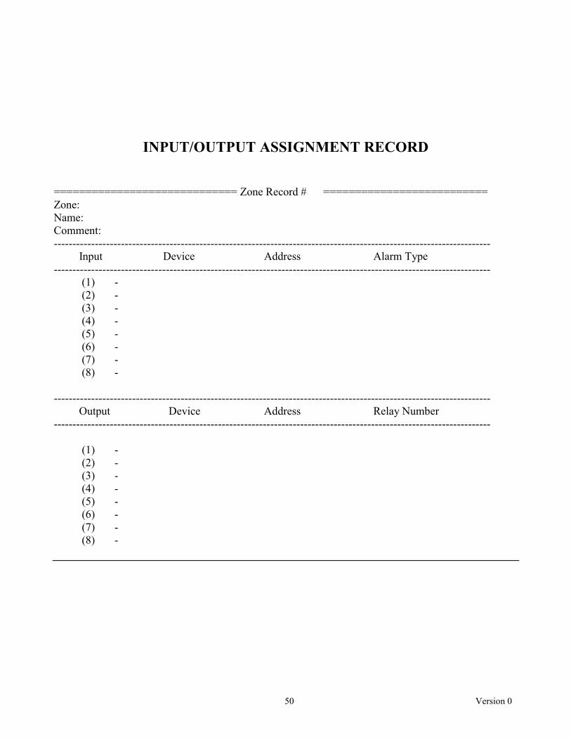
• Zone Record Input/Output Assignment Matrix – In Attachment A of this manual is a matrix to list
the inputs and outputs that will be assigned for a particular Zone Record. This should be saved for future reference. Additional copies can be made for other zone assignments.
3.2 Basic Configuration
Figure 7 shows a simple example system using the GCM II and relays for alarm annunciation. This configuration uses a PM II with two sensor cables, an AIM II, Model 300B microwave link, two (2) ROM II–16’s and the GCM II.
RO
M II–16 Tam
per
AIM
II Tamper
PM
II Tamper
MW
Rx Tam
per
MW
Tx Tamper
Zone 7 Alarm
Zone 6 Alarm
PM II C
omfail
RO
M II C
omfail
AIM II C
omfail
Zone 5 Alarm
Zone 4 Alarm
Zone 3 Alarm
Zone 2 Alarm
Zone 1 Alarm
MP
Cable A Fault
MP
Cable B Fault
Config C
hange Alarm
Service A
larm
RO
M II–16 Tam
per
Supervised A
larm
Figure 7 – Example System
11 Version 0
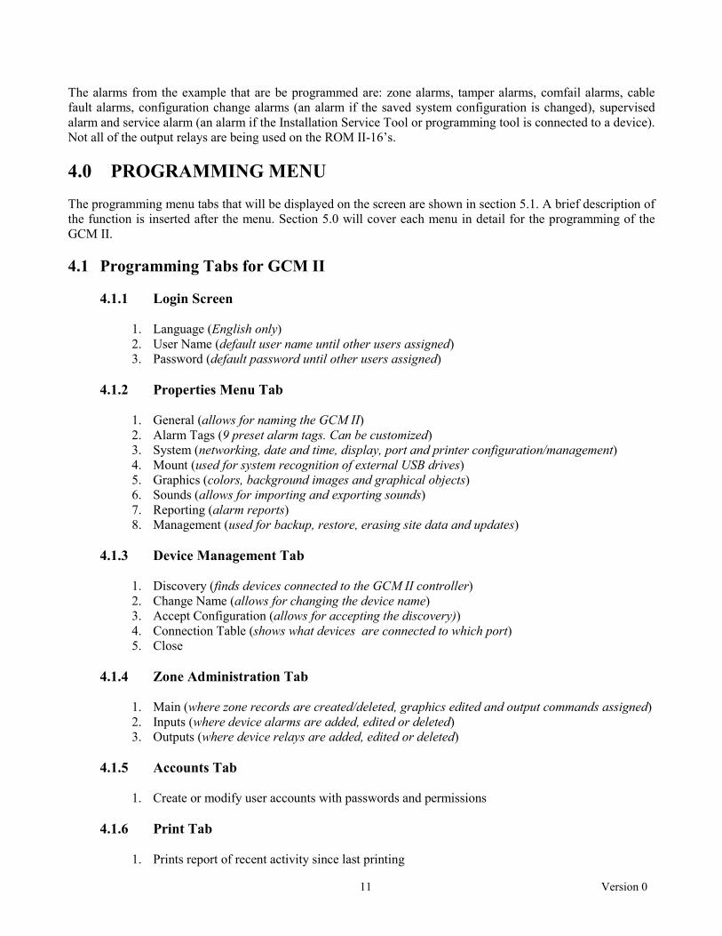
The alarms from the example that are be programmed are: zone alarms, tamper alarms, comfail alarms, cable fault alarms, configuration change alarms (an alarm if the saved system configuration is changed), supervised alarm and service alarm (an alarm if the Installation Service Tool or programming tool is connected to a device). Not all of the output relays are being used on the ROM II-16’s. 4.0 PROGRAMMING MENU The programming menu tabs that will be displayed on the screen are shown in section 5.1. A brief description of the function is inserted after the menu. Section 5.0 will cover each menu in detail for the programming of the GCM II. 4.1 Programming Tabs for GCM II 4.1.1 Login Screen
1. Language (English only) 2. User Name (default user name until other users assigned) 3. Password (default password until other users assigned)
4.1.2 Properties Menu Tab
1. General (allows for naming the GCM II) 2. Alarm Tags (9 preset alarm tags. Can be customized) 3. System (networking, date and time, display, port and printer configuration/management) 4. Mount (used for system recognition of external USB drives) 5. Graphics (colors, background images and graphical objects) 6. Sounds (allows for importing and exporting sounds) 7. Reporting (alarm reports) 8. Management (used for backup, restore, erasing site data and updates)
4.1.3 Device Management Tab
1. Discovery (finds devices connected to the GCM II controller) 2. Change Name (allows for changing the device name) 3. Accept Configuration (allows for accepting the discovery)) 4. Connection Table (shows what devices are connected to which port) 5. Close
4.1.4 Zone Administration Tab
1. Main (where zone records are created/deleted, graphics edited and output commands assigned) 2. Inputs (where device alarms are added, edited or deleted) 3. Outputs (where device relays are added, edited or deleted)
4.1.5 Accounts Tab
1. Create or modify user accounts with passwords and permissions 4.1.6 Print Tab
1. Prints report of recent activity since last printing
12 Version 0
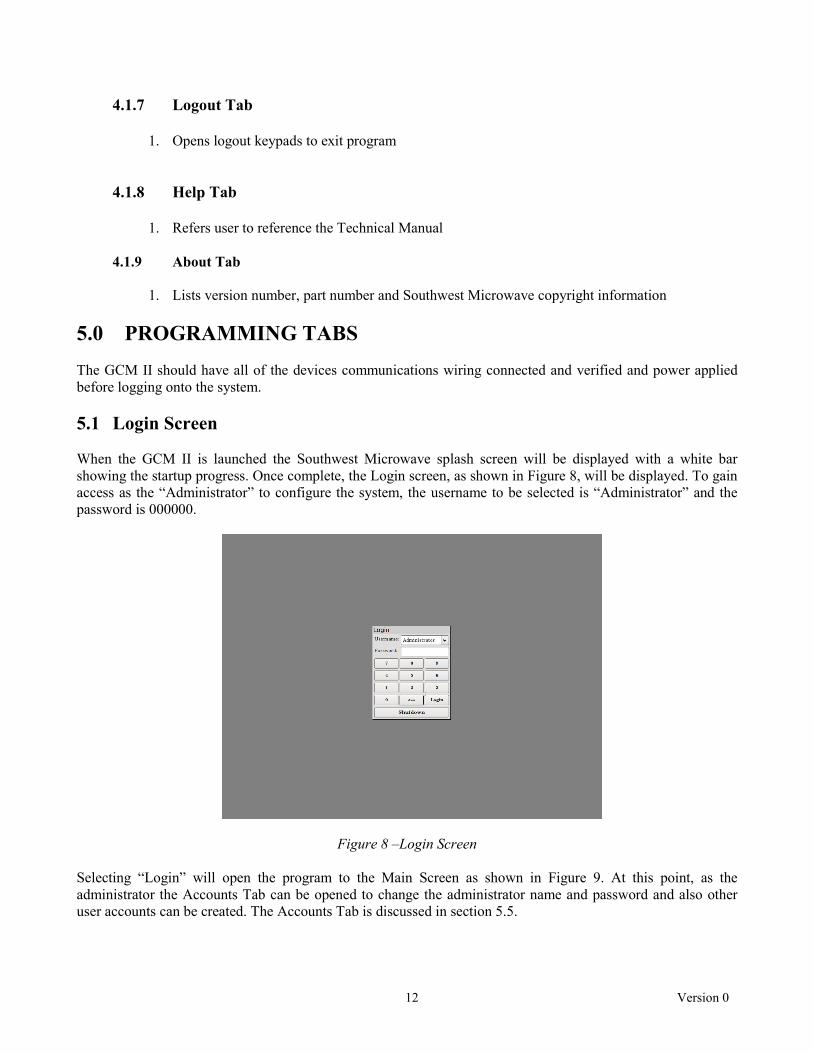
4.1.7 Logout Tab
1. Opens logout keypads to exit program 4.1.8 Help Tab
1. Refers user to reference the Technical Manual
4.1.9 About Tab
1. Lists version number, part number and Southwest Microwave copyright information 5.0 PROGRAMMING TABS The GCM II should have all of the devices communications wiring connected and verified and power applied before logging onto the system. 5.1 Login Screen When the GCM II is launched the Southwest Microwave splash screen will be displayed with a white bar showing the startup progress. Once complete, the Login screen, as shown in Figure 8, will be displayed. To gain access as the “Administrator” to configure the system, the username to be selected is “Administrator” and the password is 000000.
Figure 8 –Login Screen Selecting “Login” will open the program to the Main Screen as shown in Figure 9. At this point, as the administrator the Accounts Tab can be opened to change the administrator name and password and also other user accounts can be created. The Accounts Tab is discussed in section 5.5.

13 Version 0
Figure 9 – Main Screen 5.2 Properties Menu NOTE! When the GCM II has been programmed with a zone record the system will automatically start polling that zone record. Any alarm activity will be displayed on the screen and by the relay(s) or output command assignment(s). 5.2.1 General Selecting the “General” tab will open a “Site Name” text field box that allows for assigning a name to the GCM II as a reference as shown in Figure 10. The default name (Graphic Control Module II) will appear in the text field. Type an appropriate name in the field for the site or facility or location where the GCM II will be used. Select the “Update” button after the name in text field has been entered to keep the name or select “Cancel” to quit the operation. The text field will now display the new name. Select the “Close” button to return to the main screen.

14 Version 0
Figure 10 – General Tab 5.2.2 Alarm Tags Selecting the “Alarm Tags” tab will open the screen as shown in Figure 11. There are nine (9) default alarm tags defined. They are: Intruder, Staff, Test, Animal, Vegetation, Debris, Weather, Maintenance and Unknown. To activate alarm tagging, the check box next to “Tag Alarms” must be selected. The tag names can also be changed to meet site requirements. Highlight the word, type in new word then select “Update” to save the change. Note: changing the name after the system has been running will make it difficult to get search results from the log file for alarm reports.
Figure 11 – Alarm Tags

15 Version 0
5.2.3 System Selecting the “System” tab will open the tabs for control of Networking, Date and Time, Display, Port and Printer settings. 5.2.3.1 Networking Selecting the “Networking” tab will open the screen as shown in Figure 12. The networking settings are used to configure the GCM II when the UIST II on a server/workstation is connected through the GCM II, if system backup is to be done on a server or if a printer on a network is to be used. The settings provided are:
Host Name smiGcm
Local IP Address 192.168.1.2
Gateway IP Address 192.168.1.1
Network Address 192.168.1.0
Subnet Mask 255.255.255.0
If the GCM II is not being used with any network devices the DCHP box should be checked. If network settings are required, a companies IT person may be required to fill in the appropriate information. Once the settings have been set, select “Update” to save the changes.
Figure 12 – Network Settings 5.2.3.2 Date and Time Selecting the “Date and Time” tab will open the screen as shown in Figure 13. This tab will set the date and time for all information displayed on the screen and the time/date stamp in the log file. Selecting the pull down menu next to the “Date” line will open a calendar for selection of the month and day. Highlighting the hours, minutes or seconds in the “Time” line and selecting the directional arrows will change the time. Select the pull down menu next to the “Time Zone” to find the region where the GCM II will be used. Once the time and date have been set for the correct region, select “Update” to save the changes.

16 Version 0
Figure 13 – Date and Time 5.2.3.3 Display Selecting the “Display” tab will open the screen as shown in Figure 14. This tab will set the screen resolution for the graphics that will be used to monitor the system. From the pull down tab select the resolution that best fits the monitor that is being used. Once the resolution has been set, select “Update” to save the change.
Figure 14 – Display

17 Version 0
5.2.3.4 Port Selecting the “Port” tab will open the screen as shown in Figure 15. This tab will set the output port parameters for interfacing to other devices such as a CCTV matrix or cameras if a data stream interface is required. The parameters to be set are: Baud Rate, Stop Bits, Flow Control, Parity and Data Bits. Once the port has been set, select “Update” to save the changes. Check manufactures data for required settings.
Figure 15 – Port 5.2.3.5 Printer Selecting the “Printer” tab will open the screen as shown in Figure 16. This tab will Select, Configure and manage any printer connected to the GCM II.
Figure 16 – Printer

18 Version 0
Select the “Manage Printers” button to open the “Printer Configuration – Local Host” configuration screen. Select “New” to open the “Printer, Select Device” screen for setting the printer port or network port if used. For a stand alone GCM II select Port #1. Select “Forward” to open the list of printer manufactures and select the printer to be used. Select “Forward” to open the list of printer models and select the printer to be used. Select “Forward” to open the “Describe Printer” screen to assign a name, description and location to the printer. Select “Apply” to activate the printer. Selecting “Select/Configure Printer” will open the screen for setting properties and options for the printer. Once the printer has been selected and appropriate settings made, just close the screen. 5.2.4 Mount Selecting the “Mount” tab will open the screen as shown in Figure 17. This tab is used to find and recognize an external drive or network that will be used to import the graphic map, custom sounds and any custom graphical objects to be used by the system. The map to be imported must be in a *.jpeg format. Sounds can be a *.wav or *.mp3 file. Graphical objects need to be in a *.svg format.
Figure 17 – Mount, Remote There will be two (2) mount options available. One (1) option is “Remote” and the other option is “Removable”. The “Remote” option is to retrieve the information that may be stored on a server as shown in Figure 17. (The server must be configured as discussed in Section 5.2.3.1 – Networking). Information required to obtain the information are: Server, Share Name, User Name and Password. The “Removable” option is to retrieve the information from an external drive as shown in Figure 18. Select the arrow next to Device to find the appropriate drive (if more than one is connected). When found the device will be displayed. Select “Update Device” for the GCM II to recognize it. Once the correct drive is found, select “Mount” to enable the system to recognize that drive.

19 Version 0
After downloading any information “Unmount” must be selected before removing the external drive. Not performing this function will result in the information not being correctly copied to the drive or the server location.
Figure 18 – Mount, Removable 5.2.5 Graphics Selecting the “Graphics” tab will open the screen as shown in Figure 19. This tab is used to set up the colors drawn at the main display for all the zone graphical objects and shapes, the path to upload and download the background image and the path to upload and download graphical objects.
Figure 19 – Graphics

20 Version 0
5.2.5.1 Colors Selecting the “Colors” tab will open the screen as shown in Figure 19. This tab is used to set up the colors for all the graphical objects and shapes drawn on the main display. The actions to which colors can be set and their default colors are: Secure (Green), Alarm Unacknowledged (Blinking Red), Alarm Acknowledged (Red) and Access (Yellow). Optionally the objects or shapes can be set to blink or not blink by checking the box. By default the only one to blink is an Unacknowledged Alarm. Selecting the change color box will open a color pallet that can be used to change the color of any of these actions. The “Map” color is used to change the color of static test that has been placed on the map display. Select “Update” to save any changes. 5.2.5.2 Background Image Selecting the “Background Image” tab will open the screen as shown in Figure 20. This tab is used to upload, download or delete the graphical image that will be used to monitor the system. The recommended size is gauged by the monitor being used. Only one (1) background image is supported and must be a *.JPG format. Note: be sure the drive has been correctly mounted as stated in Section 5.2.4.
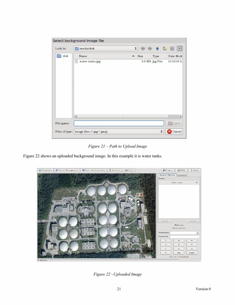
Figure 20 – Background Image To upload the image, select the “Browse” button next to “Image Upload” to open the “Select Background Image File” dialog box as shown in Figure 21. Find the *.JPG image on the external drive that will be used as the map to monitor the system and select “Open”. It will now be displayed in the Path to Upload Image box. Select “Image Upload” next to the browse button to import the image. A dialog box will open about the image size. Select “Fit” to have the map fit the monitor for size and resolution.
21 Version 0
Figure 21 – Path to Upload Image Figure 22 shows an uploaded background image. In this example it is water tanks.
Figure 22 –Uploaded Image

22 Version 0
To save the background image that may already exist on the GCM II or to save an image that was just uploaded, select the “Browse” button next to “Image Download” as shown in Figure 20 to open the “Select File for Saving Current Background Image” dialog box as shown in Figure 23.
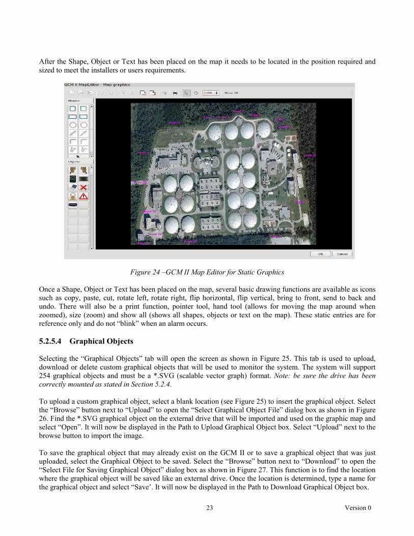
Figure 23 – Path to Download Image This function is to find the location where the image will be saved like an external drive. Once the location is determined, type a name for the image and select “Save”. It will now be displayed in the Path to Download Image box. Select “Image Download” to send it to the drive. Note: be sure the drive has been correctly unmounted as stated in Section 5.2.4 before removal. If the image being used needs to be deleted, select the “Delete Image” button. 5.2.5.3 Add Background Text and Graphics to Map Selecting the “Add Background Text and Graphics to Map” button as shown in Figure 20 will open the GCM II Map Editor – Map Graphics screen as shown in Figure 24. From here static shapes, static graphical objects and static text can be added to the map. In the case of Figure 24, static text has been added. Select a “Shape” or “Object” and drag it to the map. Available shapes are: square, dashed square, rectangle, dashed rectangle, circle, dashed circle, line, dashed line, curve, dashed curve, freehand line, dashed freehand line and text. Available objects are: microwave head right, microwave head left, MTP II, PM II, laptop computer, red X, lock, warning sign and INTREPID™ enclosure. For “Text” a text properties box will open. Type the required text in the properties box to be displayed on the map. Font choices and alignment are available for customization. If custom objects have been imported as described in Section 5.2.5.4, they would be shown here as well.
23 Version 0
After the Shape, Object or Text has been placed on the map it needs to be located in the position required and sized to meet the installers or users requirements.
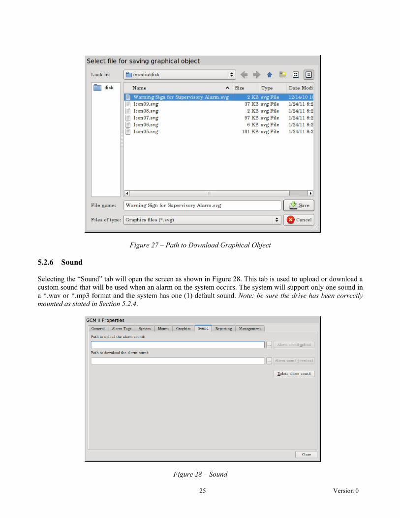
Figure 24 –GCM II Map Editor for Static Graphics Once a Shape, Object or Text has been placed on the map, several basic drawing functions are available as icons such as copy, paste, cut, rotate left, rotate right, flip horizontal, flip vertical, bring to front, send to back and undo. There will also be a print function, pointer tool, hand tool (allows for moving the map around when zoomed), size (zoom) and show all (shows all shapes, objects or text on the map). These static entries are for reference only and do not “blink” when an alarm occurs. 5.2.5.4 Graphical Objects Selecting the “Graphical Objects” tab will open the screen as shown in Figure 25. This tab is used to upload, download or delete custom graphical objects that will be used to monitor the system. The system will support 254 graphical objects and must be a *.SVG (scalable vector graph) format. Note: be sure the drive has been correctly mounted as stated in Section 5.2.4. To upload a custom graphical object, select a blank location (see Figure 25) to insert the graphical object. Select the “Browse” button next to “Upload” to open the “Select Graphical Object File” dialog box as shown in Figure 26. Find the *.SVG graphical object on the external drive that will be imported and used on the graphic map and select “Open”. It will now be displayed in the Path to Upload Graphical Object box. Select “Upload” next to the browse button to import the image. To save the graphical object that may already exist on the GCM II or to save a graphical object that was just uploaded, select the Graphical Object to be saved. Select the “Browse” button next to “Download” to open the “Select File for Saving Graphical Object” dialog box as shown in Figure 27. This function is to find the location where the graphical object will be saved like an external drive. Once the location is determined, type a name for the graphical object and select “Save’. It will now be displayed in the Path to Download Graphical Object box.

24 Version 0
Select “Download” to send it to the drive. Note: be sure the drive has been correctly unmounted as stated in Section 5.2.4 before removal.
Figure 25 – Default Graphical Objects
Figure 26 – Path to Upload Custom Graphical Object If the graphical object needs to be deleted, select the object and then select the “Delete Image” button as shown in Figure 25.
25 Version 0
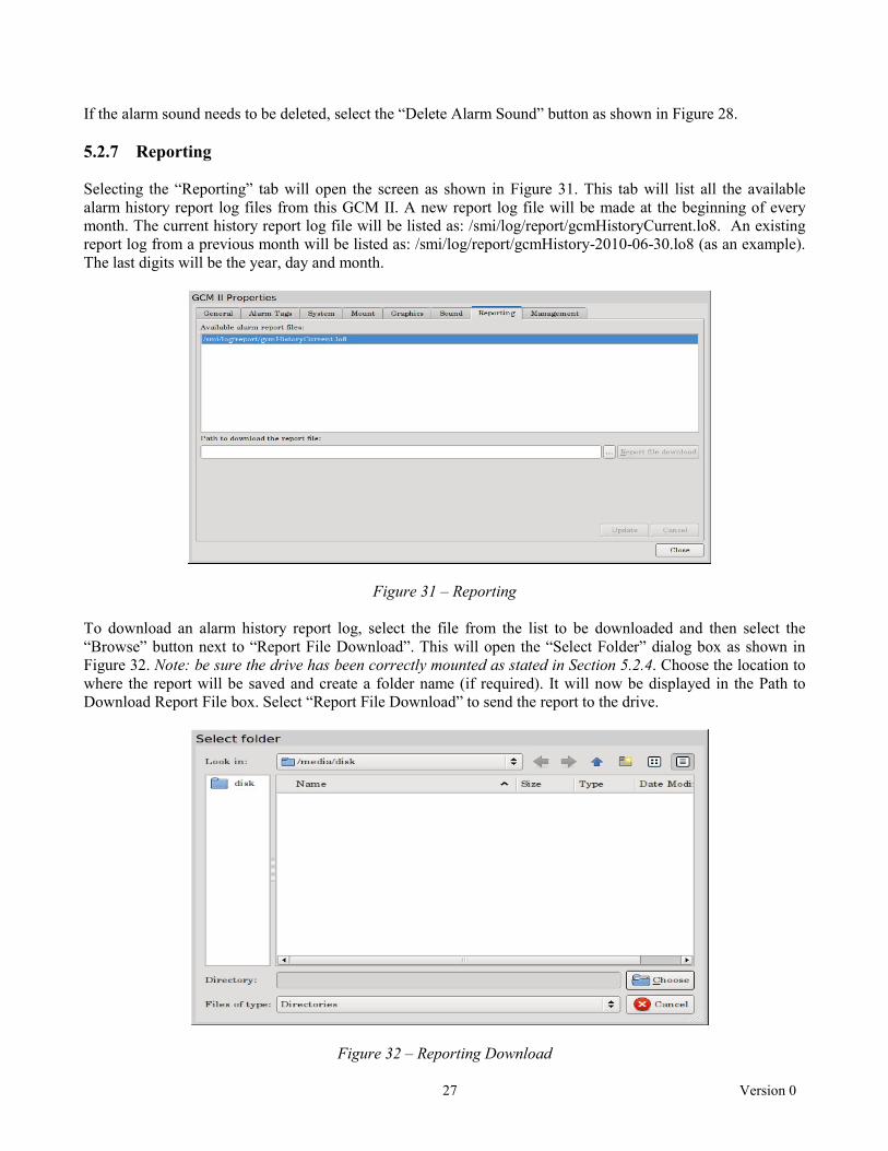
Figure 27 – Path to Download Graphical Object 5.2.6 Sound Selecting the “Sound” tab will open the screen as shown in Figure 28. This tab is used to upload or download a custom sound that will be used when an alarm on the system occurs. The system will support only one sound in a *.wav or *.mp3 format and the system has one (1) default sound. Note: be sure the drive has been correctly mounted as stated in Section 5.2.4.
Figure 28 – Sound

26 Version 0
To upload an alarm sound, select the “Browse” button next to “Alarm Sound Upload” to open the “Path to Upload Alarm Sound” dialog box as shown in Figure 29. Find the sound file on the external drive that will be used and select “Open”. It will now be displayed in the Path to Upload Alarm Sound box. Select “Alarm Sound Upload” next to the browse button to import the audio sound.
Figure 29 – Path to Upload Sound To save the sound that already exists on the GCM II, select the “Browse” button next to “Alarm Sound Download” to open the “Select File for Saving Current Alarm Sound” dialog box as shown in Figure 30. This function is to find the location where the alarm sound will be saved like an external drive. Once the location is determined, type a name for the alarm sound and select “Save”. It will now be displayed in the Path to Download Alarm Sound box. Select “Alarm Sound Download” to send it to the drive. Note: be sure the drive has been correctly unmounted as stated in Section 5.2.4 before removal.
Figure 30 – Path to Download Sound
27 Version 0
If the alarm sound needs to be deleted, select the “Delete Alarm Sound” button as shown in Figure 28. 5.2.7 Reporting Selecting the “Reporting” tab will open the screen as shown in Figure 31. This tab will list all the available alarm history report log files from this GCM II. A new report log file will be made at the beginning of every month. The current history report log file will be listed as: /smi/log/report/gcmHistoryCurrent.lo8. An existing report log from a previous month will be listed as: /smi/log/report/gcmHistory-2010-06-30.lo8 (as an example). The last digits will be the year, day and month.
Figure 31 – Reporting To download an alarm history report log, select the file from the list to be downloaded and then select the “Browse” button next to “Report File Download”. This will open the “Select Folder” dialog box as shown in Figure 32. Note: be sure the drive has been correctly mounted as stated in Section 5.2.4. Choose the location to where the report will be saved and create a folder name (if required). It will now be displayed in the Path to Download Report File box. Select “Report File Download” to send the report to the drive.
Figure 32 – Reporting Download

28 Version 0
The report now can be opened in Notepad™ or other document on another computer to evaluate the data. All keystroke functions, alarms, and events will be listed in the log along with a time and date stamp. The data can also be imported into other programs for making spreadsheets. The “Update” button will save the directory path for downloads of future reports. 5.2.8 Management Selecting the “Management” tab will open the screen as shown in Figure 33. This tab is used to upload or download the GCM II configuration files for backup and restoring, updating the GCM II and erasing all site data on the GCM II. Note: be sure the drive has been correctly mounted as stated in Section 5.2.4.
Figure 33 – Management Tab 5.2.8.1 Backup Files To backup the GCM II files from the “Backup/Restore” tab, select the “Browse” button next to “Backup” to open the dialog box as shown in Figure 34. Enter an appropriate file name for the information to be saved. The saved file will have a *.bzip2 extension. Select “Save” and the path will be displayed in the Path to Backup File box. Select “Backup” to save the information to the drive. A prompt will open stating “Operation in Progress”. Once completed, a dialog box with “Backup Successful” will be displayed. Select the “OK” button. 5.2.8.2 Restore Files To restore the GCM II files from the “Backup/Restore” tab, select the “Browse” button next to “Restore” to open the dialog box as shown in Figure 35. Find the correct backup file and select “Open”. The path will be displayed in the Path to Backup File for Restore box. Select “Restore” to upload the information to the GCM II. 5.2.8.3 Erase Site Data Selecting “Erase All Site Data” will remove all the site data that the GCM II has. A prompt stating “This will erase all the GCM II components data. This site will no longer be secure. Are you sure you want to erase all data” will be displayed. Yes or No are the options. It is recommended before installing the GCM II in a new site

29 Version 0
that this function be done. This will erase any potential data that may be on the GCM II from production testing from the factory or from a previous site where it may have been installed.
Figure 34 – Backup File
Figure 35 – Restore File

30 Version 0
5.2.8.4 Update Selecting the “Update” tab will open the screen as shown in Figure 36. This tab is used to update the GCM II software or operating system using an SMI information package (if required). Once the package is found select “Update” to send it to the GCM II
Figure 36 – Update Tab 5.3 Device Management Menu Selecting the “Device Management” tab will open the GCM II Device Management screen shown in Figure 37. This screen will be used for Discovery (discovers devices connected to the GCM II), Change Name (changing the name of a device), Accept Configuration (accepting configuration change) and Connection Table (what device are connected to which Com Ports).
Figure 37 – GCM II Device Management

31 Version 0
Typically the GCM II Devices Management screen will be blank (except for the headers and the GCM II itself) on a new installation. If it has been used before it will list previous discovered devices. It will list the Address (device address), Device Type (PM II, ROM II-16, etc), Port (A, B, C or D), Status (supported or un-supported) and Device Name (name entered for device). 5.3.1 Discovery Selecting the “Discovery” button will open the “Discovery Options” screen as shown in Figure 38. This screen will be used for discovering devices connected to the GCM II. The Device Discovery function will poll all IPP II address settings in the range from 0 to 239. The address of the GCM II is fixed at 254. The range of addresses to be polled must be entered in the “Minimum” and “Maximum” fields of Port A, Port B, Port C and/or Port D. The GCM II can have a maximum of 32 devices connected if the “Fault Tolerance” is “Disabled”. The Disabled Fault Tolerance configuration is an open loop where the communications from the GCM II port connects to the first device and ends at the last device as shown in Figure 1.
Figure 38 – Discovery Options If the “Fault Tolerance” button is “Enabled” there will be only two “Start Address” and “End Address” fields. The Fault Tolerance configuration is a closed loop as shown in Figure 39 where the communications from Port A of the GCM II connects to Port B and Port C connects to Port D through the devices. Figure 39 shows a configuration using eight (8) devices that will provide a one (1) second alarm delivery. Additional devices on the line will extend the alarm delivery by 125mS per device. Note: a maximum of 32 devices can be connected to the GCM II. Note: The address of the device must be with the discovery “Start” and “End” address. For example: if the discovery is set to find addresses 0 to 7 and a device is set to address 8, the GCM II will not find this device. Also the more addresses entered in the field the longer the search will take as the GCM II will poll for all addresses entered. For example: if there are only 8 devices connected and the Start and End address was set from 0 to 150, the GCM II will poll all 151 entered addresses.

32 Version 0
Figure 39 – Fault Tolerance Configuration To start the Device Discovery process, select the “Discover” button. If there are devices properly connected to the RS422 communications line that responds to the address poll, the GCM II will determine what type of device it is and will display it in the “New Devices” list as shown in Figure 40. This process will continuously repeat (blue scrolling bar) and update the list until the “Stop” button is selected to stop the discovery process. If there had been a previous discovery, this would be listed as “Previous Devices”.
Figure 40 – Discovery

33 Version 0
Once the “Stop” button has been selected the system will finish polling all connected devices. The “Discovery” screen will open with only the new discovered devices as shown in Figure 41. At this point any previous devices will be listed along with all new devices found. The discovery can be “Accepted” or “Rejected” by selecting one of these buttons. If there had been previous devices found and any defined zone(s) had been changed because of the new discovery, they would be listed as “Zone(s) in Error”. If the discovery is correct for all devices connected, select “Accept”. If not select “Reject”. Once accepted the GCM II Device Management screen will open listing all “Active Devices” as shown in Figure 42. All devices will now be polled by the GCM II.
Figure 41 – New Discovered Devices
Figure 42 –Discovered Devices

34 Version 0
5.3.2 Change Name If the name of the device needs to be changed or entered, select the device then select the “Change Name” button on the GCM II Device Management screen as shown in Figure 42. This will open the “Change Name” screen as shown in Figure 43. Enter the new name and select OK. The CGM II name is not changeable in this screen. If the name of the CGM II needs to be changed this must be done in the “Properties” tab under “General”.
Figure 43 – Change Device Name 5.3.3 Accept Configuration The “Accept Configuration” button on the GCM II Device Management screen as show in Figure 42 will only be active when a change has been made to a device. For example, if an input to an AIM II is change from a normally open (NO) to normally closed (NC) state, the device status will be “Compromised” as shown in Figure 44. If this change is a correct change, select the compromised device then select “Accept Configuration” to accept the change.
Figure 44 – Compromised Status

35 Version 0
5.3.4 Connection Table Selecting the “Connection Table” button on the GCM II Device Management screen as show in Figure 42 will open the “Connection Table” as shown in Figure 45. This table will list which devices by address are connect to which ports of the GCM II. In this example all devices are connected to Com Port A.
Figure 45 – Connection Table 5.4 Zone Administration Menu The “Zone Administration” menu allows for assigning inputs, outputs, zone name, comments, graphics, output commands, adding zones, deleting zones and updating changes as shown in Figure 46.
Figure 46 – Zone Administration 5.4.1 GCM II Zone Administration – Main Tab The “Main” tab will be used for creating new zones, assigning zone names, assigning zone comments, adding/editing graphics and entering Hex commands to interface with other devices such as cameras, matrix systems, DVR’s, etc It will also be used to delete zones and update the system once changes have been made.

36 Version 0
5.4.1.1 Add Zone Select the “Add Zone” button to create a new zone. For a new system, #0001 will be displayed in the “Defined Zones” tab, New Zone #0001 will be displayed in the “Zone Name” field and Comment #0001 will be displayed in the “Comment” field as shown in Figure 47. If it is an existing system it will start with the next number in line from the last zone created. The next time the “Add Zone” button is selected it will display #0002 and increase every time the button is selected. The GCM II is capable of having 1024 zones. The zones will be listed in alphabetical order so for numeric order there must be a four (4) digit number. Once zones are defined they will be listed in the “Defined Zones” field pull down tab.
Figure 47 – Add Zone 5.4.1.2 Zone Name The “Zone Name” field is used to assign a name to the zone being created. This name will be displayed in the Access/Secure and Alarm fields for the operators plus used in the alarm reports and log file. The most common entries are Zone 0001, Zone 0002, Zone 003, tamper, etc. 5.4.1.3 Comment The “Comment” field is used to assign a description or comment to the zone being created. This name will be used for reference only. The comment should be something unique about the zone, equipment or site. 5.4.1.4 Graphics Selecting the “Edit Graphics” button will open the screen to add active shapes, graphical objects or text for that zone to the map that has been imported for monitoring as shown in Figure 48. Select a “Shape” or “Object” and drag it to the map. Available shapes are: square, dashed square, rectangle, dashed rectangle, circle, dashed circle, line, dashed line, curve, dashed curve, freehand line, dashed freehand line and text. Available objects are: microwave head right (for tamper alarm), microwave head left (for tamper alarm), MTP II (for tamper alarm), PM II (for tamper alarm), laptop (for service alarm), lock (for configuration change alarm, red X (for communications failure alarm), warning sign (for supervisory alarm) and INTREPID™ enclosure (for the AIM II and ROM II tamper alarm). If custom objects have been imported as described in
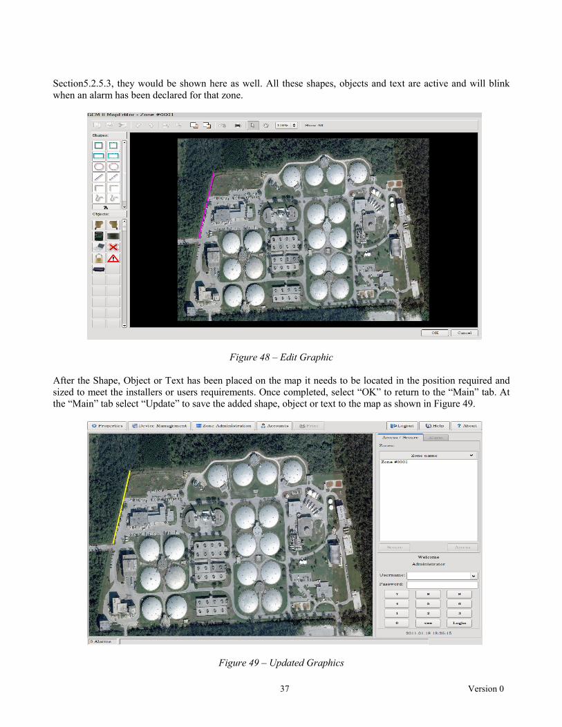
37 Version 0
Section5.2.5.3, they would be shown here as well. All these shapes, objects and text are active and will blink when an alarm has been declared for that zone.
Figure 48 – Edit Graphic After the Shape, Object or Text has been placed on the map it needs to be located in the position required and sized to meet the installers or users requirements. Once completed, select “OK” to return to the “Main” tab. At the “Main” tab select “Update” to save the added shape, object or text to the map as shown in Figure 49.
Figure 49 – Updated Graphics

38 Version 0
Once a shape, object or text has been placed on the map several basic drawing functions are available as icons such as, copy, paste, cut, rotate left, rotate right, flip horizontal, flip vertical, bring to front, send to back, undo, print, pointer tool, hand tool (allows for moving the map around), size (zoom) and show all (shows all shapes or objects on the map). 5.4.1.5 Output Command The “Output Command” is for inserting a Hexadecimal command string for that zone to interface with other devices such as cameras, camera matrix systems, DVR’s, etc. Please refer to that manufactures documentation for their command structure. The output command can have up to 64 characters. Figure 50 is an ASCII character to Hexadecimal numbers table that can be used as a reference for inserting the command string into the Output Command box.
ACSII Characters to Hexadecimal Numbers
Character Hex Character Hex Character Hex Character Hex
(nul) 00 (sp) 20 @ 40 ` 60 (soh) 01 ! 21 A 41 a 61 (stx) 02 " 22 B 42 b 62 (etx) 03 # 23 C 43 c 63 (eot) 04 $ 24 D 44 d 64 (enq) 05 % 25 E 45 e 65 (ack) 06 & 26 F 46 f 66 (bel) 07 ' 27 G 47 g 67 (bs) 08 ( 28 H 48 h 68 (ht) 09 ) 29 I 49 i 69 (nl) 0a * 2a J 4a j 6a (vt) 0b + 2b K 4b k 6b (np) 0c , 2c L 4c l 6c (cr) 0d ‐ 2d M 4d m 6d (so) 0e . 2e N 4e n 6e (si) 0f / 2f O 4f o 6f (dle) 10 0 30 P 50 p 70 (dc1) 11 1 31 Q 51 q 71 (dc2) 12 2 32 R 52 r 72 (dc3) 13 3 33 S 53 s 73 (dc4) 14 4 34 T 54 t 74 (nak) 15 5 35 U 55 u 75 (syn) 16 6 36 V 56 v 76 (etb) 17 7 37 W 57 w 77 (can) 18 8 38 X 58 x 78 (em) 19 9 39 Y 59 y 79 (sub) 1a : 3a Z 5a z 7a (esc) 1b ; 3b [ 5b { 7b

39 Version 0
(fs) 1c < 3c \ 5c | 7c (gs) 1d = 3d ] 5d } 7d (rs) 1e > 3e ^ 5e ~ 7e (us) 1f ? 3f _ 5f (del) 7f
Figure 50 – Hexadecimal Chart
As an example, an ASCII command is 5Ma2#a3\a for Go to camera 2, preset 3 on monitor 5. The Hex code to type into the Output Command filed is 35 4d 61 32 23 61 33 5c 61 (no spaces required – spaces are for clarity). Once all items from steps 5.4.1.1 to 5.4.1.5 have been completed for the zone, select the “Update” button to save the configured information. Once a zone is created and updated, the GCM II will begin polling that device for alarm information. Perform steps 5.4.1.1 to 5.4.1.5 for all zones that need to be created. 5.4.1.6 Delete Zone Any zone that has been created can be deleted. Select the zone to be deleted from the Defined Zones list and select the “Delete Zone” button. After deletion, select the “Update” button to save the configuration. 5.4.2 GCM II Zone Administration – Inputs Tab Selecting the “Inputs” tab will open the Inputs Assignment screen as shown in Figure 51. On a new installation the screen should be blank except for the headers which are: Address, Device Type, Device Name, Input Type, Cable ID, Start Subcell, End Subcell and Input. A maximum of eight (8) inputs can be assigned for any zone.
Figure 51 – Inputs Tab Selecting the “Add” button will open the “Modify Zone Input Assignment” screen as shown in Figure 52. On this screen, only devices that had been found during the discovery process will be listed in the Device Address, Type and Name pull down menu as well as the GCM II itself.

40 Version 0
Figure 52 – Modify Zone Input Assignment The pull down menu lists the Device Address, Device Type and Device Name of all discovered devices. Figure 52 show an Address of “0” (Device Address) for the PM II (Device Type) and PM II (Device Name). The Input Type pull down menu will list the assignable inputs for each device that has been discovered. The assignable inputs from devices are:
• Alarm Input Module II
Enclosure Tamper - activation of the tamper switch Comfail – loss of communications with the GCM II Device Configuration Change – any changes to the setup, such as NO vs. NC, Supervised vs.
Non-Supervised Alarm Input – activation of one of the 8 inputs Supervised Alarm – open or short of a Supervised Input
• Relay Output Module II
Enclosure Tamper - activation of the tamper switch Comfail – loss of communications with the GCM II Device Configuration Change – any changes to the setup, such as a change to the comfail
timeout jumper
• MicroTrack™ II
Enclosure Tamper - activation of the tamper switch Comfail – loss of communications with the GCM II Device Configuration Change – any changes to the setup, such as control parameters,
calibration, threshold, etc Cable Alarm – detection of an alarm by the sensor cable A or B Cable Fault – detection of a cable fault condition on the sensor cable A or B UIST II Service Alarm – activated when the Universal Installation Service Tool II is connected
to the sensor
• MicroPoint™ II
Enclosure Tamper - activation of the tamper switch Comfail – loss of communications with the GCM II Device Configuration Change – any changes to the setup, such as control parameters,
calibration, threshold, etc. Cable Alarm – detection of an alarm by the sensor cable A or B

41 Version 0
Cable Fault – detection of a cable fault condition on the sensor cable A or B UIST II Service Alarm – activated when the Universal Installation Service Tool II is connected
to the sensor External Input Alarm – detection of an alarm from an auxiliary device (MW, IR, gate contact,
etc.)
• Microwave Model 330
Enclosure Tamper - activation of the tamper switch, transmitter, receiver or transceiver Comfail – loss of communications with the GCM II Device Configuration Change – any changes to the setup, such as control parameters, threshold,
etc. Microwave Sensor Alarm – detection of an alarm by the sensor Path Fault – alarm from a change in the received signal strength (alignment) UIST II Service Alarm – activated when the Universal Installation Service Tool II is connected
to the sensor Auxiliary Input – detection of an alarm from an auxiliary device (MW, IR, gate contact, etc.)
• Graphic Control Module II
Line Break – notification that the communications line in the Fault Tolerant configuration has
been broken Select the device type, such as PM II as an example, from the drop down menu then select the type of alarm from that device to be assigned, such as Cable Alarm as an example. Selecting “OK” will now put the information into the “Inputs” tab. Selecting “Update” will save the assignment as shown in Figure 53.
Figure 53 – Assigned Input When assigning Cable Alarms from a PM II or MTP II the Input Type will ask for the Cable ID (A or B) and the Start and End Subcell numbers as shown in Figure 54. For Cable Faults it will ask for the cable ID (A or B). For an AIM II it will ask for the Input number.

42 Version 0
Figure 54 – Cable Alarm Assignment This same screen can also be used to “Edit” or “Delete” the information in a particular zone by selecting the entry and selecting the “Edit” or “Delete” button. Once an input is created and updated, the GCM II will begin polling that device for alarm information. Perform the input assignment for all zones that need to be created. 5.4.3 GCM II Zone Administration – Outputs Tab Selecting the “Outputs” tab will open the Outputs Assignment screen as shown in Figure 55. On a new installation the screen should be blank except for the headers which are: Address, Device Type, Device Name and Relay Number. A maximum of eight (8) outputs can be assigned for any zone.
Figure 55 – Outputs Tab Selecting the “Add” button will open the “Modify Zone Relay Output Assignment” screen as shown in Figure 56. On this screen, only devices with relay outputs, such as the ROM II-8 and ROM II-16 that have been found

43 Version 0
during the discovery process will be listed. The ROM II-8 has eight (8) relay outputs and the ROM II-16 has sixteen (16) relay outputs.
Figure 56 – Modify Zone Relay Output Assignment The pull down menu lists the Device Address, Device Type and Device Name of all discovered devices that have relay outputs. The Output Relay pull down menu will list the assignable relay numbers for each device that has been discovered. Select the device type, such as ROM II-16 as an example, from the drop down menu then select the relay number from that device to be assigned, such as Relay # 1 as an example. Selecting “OK” will now put the information into the “Outputs” tab. Selecting “Update” will save the assignment as shown in Figure 57.
Figure 57 – Assigned Relay Output This same screen can also be used to “Edit” or “Delete” the information in a particular zone by selecting the entry and selecting the “Edit” or “Delete” button. Once an output is created and updated, the GCM II will begin polling that device for alarm information. Perform the output assignment for all zones that need to be created.
44 Version 0
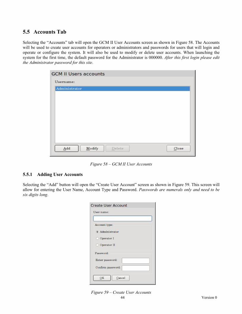
5.5 Accounts Tab Selecting the “Accounts” tab will open the GCM II User Accounts screen as shown in Figure 58. The Accounts will be used to create user accounts for operators or administrators and passwords for users that will login and operate or configure the system. It will also be used to modify or delete user accounts. When launching the system for the first time, the default password for the Administrator is 000000. After this first login please edit the Administrator password for this site.
Figure 58 – GCM II User Accounts 5.5.1 Adding User Accounts Selecting the “Add” button will open the “Create User Account” screen as shown in Figure 59. This screen will allow for entering the User Name, Account Type and Password. Passwords are numerals only and need to be six digits long.
Figure 59 – Create User Accounts

45 Version 0
There are three (3) types of user accounts:
Administrator - has access to all functions of the GCM II Operator I – has Access, Secure, Acknowledge, Reset and Print permissions Operator II – has Acknowledge, Reset and Print permissions only
Note: if the alarm tagging function has been activated, all users will have this permission. Enter the user’s name then select the account type for that user. Enter a password for that user then enter the password again for confirmation. Select “OK” to add the user to the list. Perform this operation for all users and administrators that will be operating this system. It is recommended that the Administrator create a list of all users and passwords for their records and reference. 5.5.2 Modifying User Accounts Selecting the “Modify” button will open the “Modify User Account” screen as shown in Figure 60. This screen will allow for modifying the User Name, Account Type and Password.
Figure 60 – Modify User Accounts Enter the edit for the user’s name. Select the account type for the edit of that user. Select “OK” to add these modifications. Perform this operation for all modifications to a user account. If the password for a user needs to be modified, select the “Change Password” button to open the ”Set Password” screen as shown in Figure 61. Enter the new password and then enter the password again for confirmation. Select “OK” to add these modifications. Perform this operation for all password modifications to a user account. If the password for the Administrator needs to be modified, select the “Change Password” button to open the “Set Password” screen. Enter the old/existing password then the new password and then enter the password again for confirmation. Select “OK” to add these modifications. Perform this operation for all password modifications to an administrator account.

46 Version 0
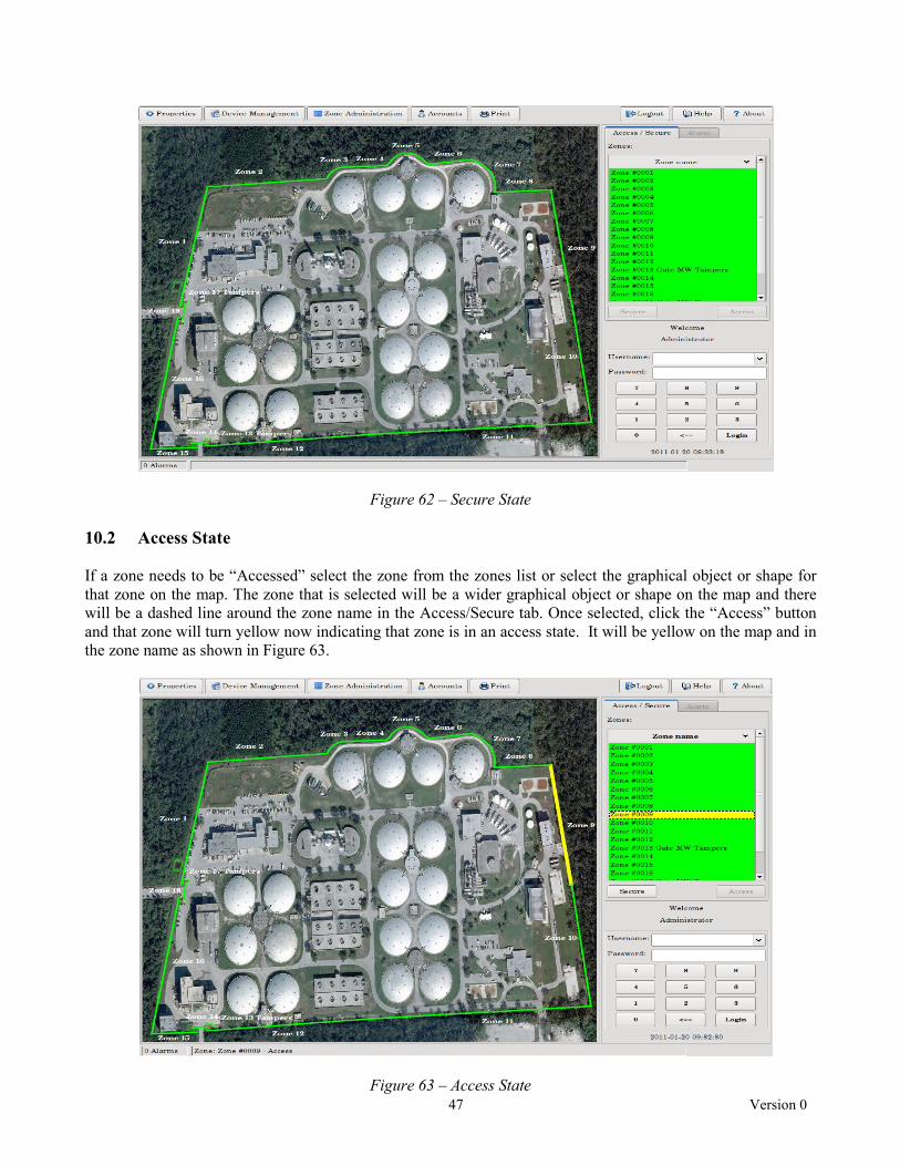
Figure 61 – Set Password The User Accounts can be deleted by selecting the user then selecting the “Delete” button. 6.0 Print The print function will print all system activity since the last report was printed once the “Print” button has been selected. Ensure a printer is connected and working properly before the print button is selected. If the printer is not connected or working properly and the print button have been selected, the system activity will be lost. 7.0 Logout Selecting the “Logout” tab will open the keypad to logout of the system. Enter the password and select logout to close out of the system. 8.0 Help The “Help” tab shows the Southwest Microwave, Inc. logo plus the GCM II and refers back to the manual. 9.0 About The “About” tab will list the copyright information, the version number of the GCM II and the part number. 10.0 GCM II Operations To operate the system first find the user name from the pull down menu above the keypad on the screen. Enter the password and select “Login”. The time and date is shown below the keypad. 10.1 Secure State In the “Secure” state all graphical objects or shapes on the map will be green to show they are in a secure state as shown in Figure 62. All zones listed in the “Zones” field under “Zone Name” in the Access/Secure tab will also be green showing that they are in a secure state.
47 Version 0
Figure 62 – Secure State 10.2 Access State If a zone needs to be “Accessed” select the zone from the zones list or select the graphical object or shape for that zone on the map. The zone that is selected will be a wider graphical object or shape on the map and there will be a dashed line around the zone name in the Access/Secure tab. Once selected, click the “Access” button and that zone will turn yellow now indicating that zone is in an access state. It will be yellow on the map and in the zone name as shown in Figure 63.
Figure 63 – Access State
48 Version 0
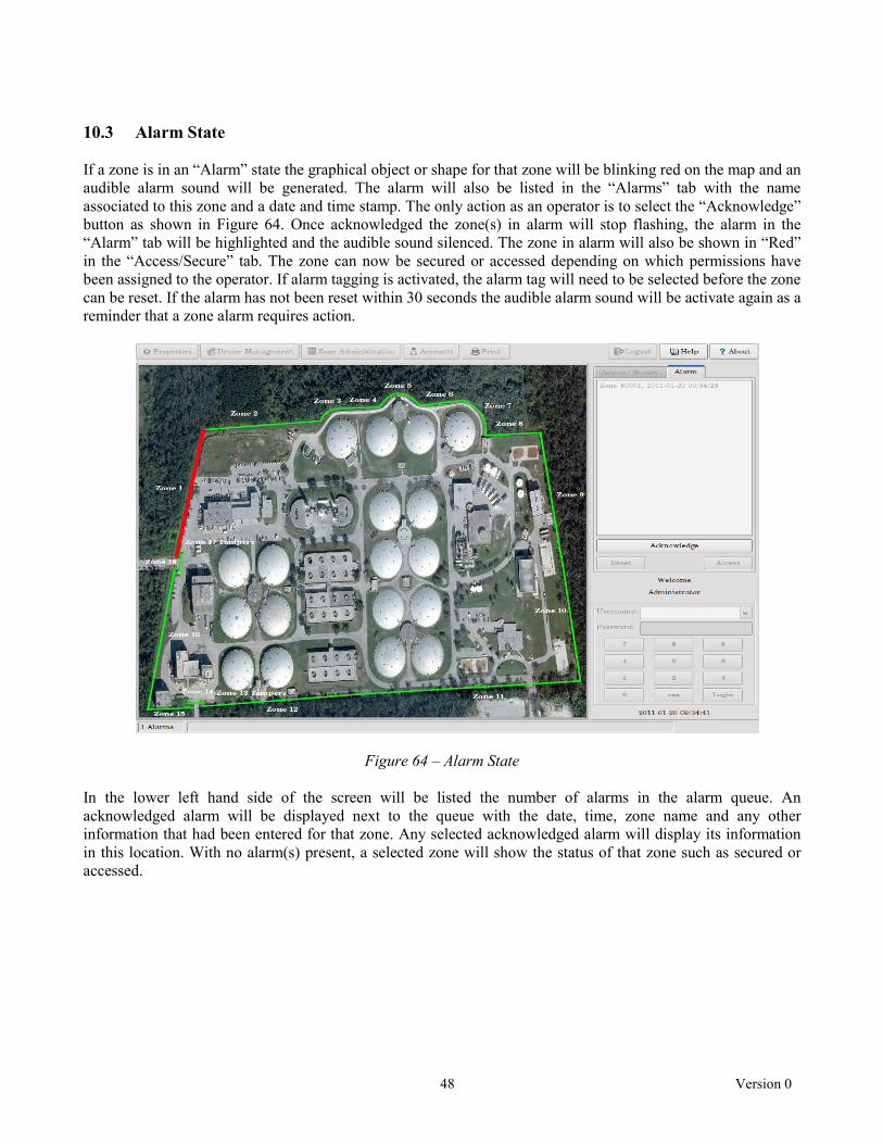
10.3 Alarm State If a zone is in an “Alarm” state the graphical object or shape for that zone will be blinking red on the map and an audible alarm sound will be generated. The alarm will also be listed in the “Alarms” tab with the name associated to this zone and a date and time stamp. The only action as an operator is to select the “Acknowledge” button as shown in Figure 64. Once acknowledged the zone(s) in alarm will stop flashing, the alarm in the “Alarm” tab will be highlighted and the audible sound silenced. The zone in alarm will also be shown in “Red” in the “Access/Secure” tab. The zone can now be secured or accessed depending on which permissions have been assigned to the operator. If alarm tagging is activated, the alarm tag will need to be selected before the zone can be reset. If the alarm has not been reset within 30 seconds the audible alarm sound will be activate again as a reminder that a zone alarm requires action.
Figure 64 – Alarm State In the lower left hand side of the screen will be listed the number of alarms in the alarm queue. An acknowledged alarm will be displayed next to the queue with the date, time, zone name and any other information that had been entered for that zone. Any selected acknowledged alarm will display its information in this location. With no alarm(s) present, a selected zone will show the status of that zone such as secured or accessed.

49 Version 0
ATTACHMENT A
50 Version 0
INPUT/OUTPUT ASSIGNMENT RECORD
============================= Zone Record # ========================== Zone: Name: Comment: --------------------------------------------------------------------------------------------------------------------- Input Device Address Alarm Type --------------------------------------------------------------------------------------------------------------------- (1) - (2) - (3) - (4) - (5) - (6) - (7) - (8) - --------------------------------------------------------------------------------------------------------------------- Output Device Address Relay Number --------------------------------------------------------------------------------------------------------------------- (1) - (2) - (3) - (4) - (5) - (6) - (7) - (8) -

51 Version 0