Embed Size (px)
Citation preview
FUGRO EARTHDATA, INC. GCMRC 2013 ORTHO IMAGERY AND DSM TASK ORDER NO. G13PD00082 JANUARY 17, 2013
Turning Spatial Data into Knowledge
GCMRC 2013 Ortho Imagery and DSM Propos a l
Submitted to: Robert Kelly
Commercial Partnerships Team – MS-665 United States Geological Survey
Geospatial Products and Services Contract National Geospatial Technical Operations Center
1400 Independence Road Rolla, MO 65401
Task Order No.: G13PD00082
Submitted by: Fugro EarthData, Inc. 7320 Executive Way
Frederick, Maryland 21704 TEL + 1 301 948 8550 FAX + 1 301 963 2064
FUGRO EARTHDATA, INC. GCMRC 2013 ORTHO IMAGERY AND DSM TASK ORDER NO. G13PD00082 JANUARY 17, 2013
Turning Spatial Data into Knowledge
Table of Contents 1 PROJECT OVERVIEW ............................................................................................................................ 1 2 PROJECT PLAN ..................................................................................................................................... 1 3 GROUND CONTROL .............................................................................................................................. 1 4 AIRBORNE IMAGE ACQUISITION ........................................................................................................ 1 4.1 ADS80-SH82 Flight Planning ................................................................................................................ 1 4.1.1 Preliminary Acquisition Plan ................................................................................................................ 2 4.1.2 Preliminary Flight Plan .......................................................................................................................... 3 4.2 Digital Camera Specifications .............................................................................................................. 3 4.3 Airborne GPS .......................................................................................................................................... 4 4.4 Calibration of the ADS80-SH82 Camera .............................................................................................. 4 4.5 Conditions during Aerial Image Acquisition ....................................................................................... 4 5 AEROTRIANGULATION ......................................................................................................................... 5 6 ORTHOPHOTO PRODUCTION .............................................................................................................. 5 6.1 Orthophoto Accuracy Standards, Datum, and Projection ................................................................. 5 6.2 Image Rectification, Radiometric Processing, and Conversions ..................................................... 6 7 DIGITAL SURFACE MODEL (DSM) ACCURACY ................................................................................. 6 8 METADATA AND MEDIA ....................................................................................................................... 7 9 PROJECT DELIVERABLES ................................................................................................................... 7 10 PROJECT SCHEDULE ........................................................................................................................... 7 11 ATTACHMENTS ...................................................................................................................................... 7
FUGRO EARTHDATA, INC. GCMRC 2013 ORTHO IMAGERY AND DSM TASK ORDER NO. G13PD00082 JANUARY 17, 2013
Turning Spatial Data into Knowledge 1
1 PROJECT OVERVIEW
In response to the Task Order Detail, received December 18, 2012, prepared by the United States Geological Survey (USGS), the Fugro team has prepared the following technical proposal and cost estimate for aerial acquisition and development to support 15 to 20 cm orthoimagery of the Grand Canyon from the 2 km upstream from the Glen Canyon Dam in Lake Powell to Pierce Ferry in Lake Mead.
2 PROJECT PLAN
For this task order, Fugro proposes to acquire all aerial photography using the Leica ADS80-SH82 digital camera, combined with airborne GPS and inertial measurement (IMU) data. This raw data will be processed using Fugro’s exclusive Pixel Factory™ system combined with an autocorrelated digital surface model to develop 20 cm ground sample distance (GSD) or better, 4-band digital orthophotography covering the Colorado River corridor from the Glen Canyon Dam at Lake Powell down to (but not including) Lake Mead, as defined by the USGS in Contract No. G11PC00014, Task Order G13PD00082 for GCMRC 2013 Ortho Imagery and DSM.
3 GROUND CONTROL
The ADS80-SH82 digital imaging makes extremely effective use of GPS and IMU technology. The Flight crew will coordinate with the GCMRC GPS survey crews to ensure that a minimum of two (2) GPS base stations are operating during airborne acquisition within approximately 30 km of the data acquisition and that the GPS constellation has an adequate number of satellites above the horizon to ensure sufficient Position Dilution of Precision (PDOP).
In coordination with the Fugro flight crew, all surveying activities will be performed by the GCMRC survey team. Fugro and the GCMRC survey team will work together to identify the number and locations of the ground control points to be used for quality assurance/quality control validation by the USGS on this project. The ground survey will be documented in the project metadata.
It is understood that the GCMRC surveyor needs to update the xls of control panels to reflect the NA2011 values. The surveyor will also review the new panel positions that were suggested by Fugro and indicate which panels the GCMRC can accommodate.
4 AIRBORNE IMAGE ACQUISITION
The following sections discuss the sensor to be used and the conditions required to complete the aerial image acquisition portion of the project to the required specifications and within the required time frame.
4.1 ADS80-SH82 Flight Planning
As defined in the task order, the area to be mapped covers the entire extent of the river corridor, starting approximately 2 km upstream from Glen Canyon Dam in Lake Powell and ending at Pierce Ferry in Lake Mead, including confluence segments of 7 major tributaries, specifically, the Little Colorado River to Blue Springs, the Paria River, Shinumo Creek, Kanab Creek, Bright Angel Creek, Tapeats Creek, and Havasu Creek. The data collection is to occur during low steady flow from Glen Canyon Dam, which will occur during steady low water conditions between the start of Memorial Day weekend in 2013 and the middle of June 2013.
The preliminary acquisition plan shown in Section 4.1.1 below identifies Fugro’s plan for acquiring this data in a five period beginning on the first day of stead low flow per the calculations provided in the “May-June 2013 FLOW_SCENARIO.xls” document.

FUGRO EARTHDATA, INC. GCMRC 2013 ORTHO IMAGERY AND DSM TASK ORDER NO. G13PD00082 JANUARY 17, 2013
Turning Spatial Data into Knowledge 2
4.1.1 Preliminary Acquisition Plan
Overflights will be coordinated with the Grand Canyon National Park Service (NPS) and will conform to park regulations (FAA Reg 93 Subpart U.doc and Special FAR 50-2.doc). Fugro and GCMRC will work with the Grand Canyon Park and Department of Interior aircraft safety officers to obtain a flight permit based on the project flight plan.
To obtain flight permits, Fugro will provide the pilots’ names and contact information and the type of aircraft (and its identification) to be used, as well as a flight plan (map) showing flight path and altitude of each flight line.
Fugro Pilots will take the NPS Flight Safety course prior to their arrival in Arizona, even if they have completed the course in prior years. Fugro Flight crews will meet at the Grand Canyon Airport with the Park Service flight coordinator the day before commencement of data collection for a final briefing.
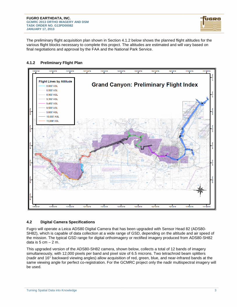
The acquisition flight plan is designed to acquire ADS80-SH82 digital imagery at a 15 to 20 cm GSD, with a planned minimum sidelap of 30%. Fugro will develop the required color orthoimagery at a 20 cm GSD or better except as noted below.
Note: The values of 8,000' and 11,000' represent ASL (above sea level) altitudes required for flying the aircraft. The ADS80 intrinsic GSD will be based on the AMT (above mean terrain) altitude. The greatest AMT altitude in project area is 5950', which yields a planned GSD of 20 cm. So, the GSD will be 20 cm or better throughout the project. The one exception is in areas where we must fly higher due to restricted airspace; in those areas the GSD increases to as much as 27 cm.
FUGRO EARTHDATA, INC. GCMRC 2013 ORTHO IMAGERY AND DSM TASK ORDER NO. G13PD00082 JANUARY 17, 2013
Turning Spatial Data into Knowledge 3
The preliminary flight acquisition plan shown in Section 4.1.2 below shows the planned flight altitudes for the various flight blocks necessary to complete this project. The altitudes are estimated and will vary based on final negotiations and approval by the FAA and the National Park Service.
4.1.2 Preliminary Flight Plan
4.2 Digital Camera Specifications
Fugro will operate a Leica ADS80 Digital Camera that has been upgraded with Sensor Head 82 (ADS80-SH82), which is capable of data collection at a wide range of GSD, depending on the altitude and air speed of the mission. The typical GSD range for digital orthoimagery or rectified imagery produced from ADS80-SH82 data is 5 cm – 2 m.
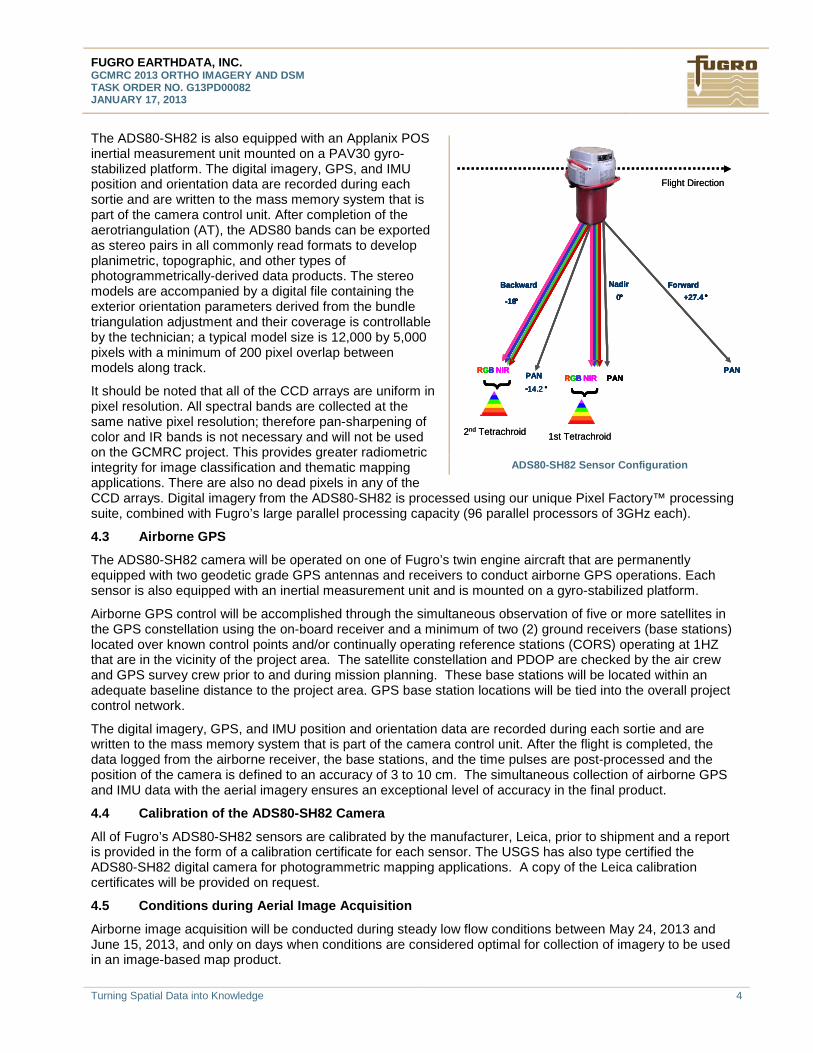
This upgraded version of the ADS80-SH82 camera, shown below, collects a total of 12 bands of imagery simultaneously, with 12,000 pixels per band and pixel size of 6.5 microns. Two tetrachroid beam splitters (nadir and 16° backward viewing angles) allow acquisition of red, green, blue, and near-infrared bands at the same viewing angle for perfect co-registration. For the GCMRC project only the nadir multispectral imagery will be used.
FUGRO EARTHDATA, INC. GCMRC 2013 ORTHO IMAGERY AND DSM TASK ORDER NO. G13PD00082 JANUARY 17, 2013
Turning Spatial Data into Knowledge 4
The ADS80-SH82 is also equipped with an Applanix POS inertial measurement unit mounted on a PAV30 gyro-stabilized platform. The digital imagery, GPS, and IMU position and orientation data are recorded during each sortie and are written to the mass memory system that is part of the camera control unit. After completion of the aerotriangulation (AT), the ADS80 bands can be exported as stereo pairs in all commonly read formats to develop planimetric, topographic, and other types of photogrammetrically-derived data products. The stereo models are accompanied by a digital file containing the exterior orientation parameters derived from the bundle triangulation adjustment and their coverage is controllable by the technician; a typical model size is 12,000 by 5,000 pixels with a minimum of 200 pixel overlap between models along track.
It should be noted that all of the CCD arrays are uniform in pixel resolution. All spectral bands are collected at the same native pixel resolution; therefore pan-sharpening of color and IR bands is not necessary and will not be used on the GCMRC project. This provides greater radiometric integrity for image classification and thematic mapping applications. There are also no dead pixels in any of the CCD arrays. Digital imagery from the ADS80-SH82 is processed using our unique Pixel Factory™ processing suite, combined with Fugro’s large parallel processing capacity (96 parallel processors of 3GHz each).
4.3 Airborne GPS
The ADS80-SH82 camera will be operated on one of Fugro’s twin engine aircraft that are permanently equipped with two geodetic grade GPS antennas and receivers to conduct airborne GPS operations. Each sensor is also equipped with an inertial measurement unit and is mounted on a gyro-stabilized platform.
Airborne GPS control will be accomplished through the simultaneous observation of five or more satellites in the GPS constellation using the on-board receiver and a minimum of two (2) ground receivers (base stations) located over known control points and/or continually operating reference stations (CORS) operating at 1HZ that are in the vicinity of the project area. The satellite constellation and PDOP are checked by the air crew and GPS survey crew prior to and during mission planning. These base stations will be located within an adequate baseline distance to the project area. GPS base station locations will be tied into the overall project control network.
The digital imagery, GPS, and IMU position and orientation data are recorded during each sortie and are written to the mass memory system that is part of the camera control unit. After the flight is completed, the data logged from the airborne receiver, the base stations, and the time pulses are post-processed and the position of the camera is defined to an accuracy of 3 to 10 cm. The simultaneous collection of airborne GPS and IMU data with the aerial imagery ensures an exceptional level of accuracy in the final product.
4.4 Calibration of the ADS80-SH82 Camera
All of Fugro’s ADS80-SH82 sensors are calibrated by the manufacturer, Leica, prior to shipment and a report is provided in the form of a calibration certificate for each sensor. The USGS has also type certified the ADS80-SH82 digital camera for photogrammetric mapping applications. A copy of the Leica calibration certificates will be provided on request.
4.5 Conditions during Aerial Image Acquisition
Airborne image acquisition will be conducted during steady low flow conditions between May 24, 2013 and June 15, 2013, and only on days when conditions are considered optimal for collection of imagery to be used in an image-based map product.
ADS80-SH82 Sensor Configuration
+27.4 °
-14.2 °PAN
PANRGB NIR PAN
0°
RGB NIR
-16°
{ {
ForwardBackward Nadir+27.4 °
-14.2 °PAN
PANRGB NIR PAN
0°
RGB NIR
-16°
{ {
ForwardBackward Nadir
2nd Tetrachroid 1st Tetrachroid
Flight Direction
+27.4 °
-14.2 °PAN
PANRGB NIR PAN
0°
RGB NIR
-16°
{ {
ForwardBackward Nadir+27.4 °
-14.2 °PAN
PANRGB NIR PAN
0°
RGB NIR
-16°
{ {
ForwardBackward Nadir
2nd Tetrachroid 1st Tetrachroid
Flight Direction
FUGRO EARTHDATA, INC. GCMRC 2013 ORTHO IMAGERY AND DSM TASK ORDER NO. G13PD00082 JANUARY 17, 2013
Turning Spatial Data into Knowledge 5
Minimal shadow conditions
Sun angle is 65° or greater above the horizon
Acquisition area is free of clouds, smoke, haze
Cloudy weather may extend the flight window during the project, but will require prior approval by the Bureau of Reclamation.
The GCMRC flight coordinator (Phil Davis) reserves the right to ground flights on any day based having unacceptable weather conditions (e.g., cloud cover or rain).
The flight crew will contact the GCMRC flight coordinator at 928-556-7084 each morning for that determination. Progress will also be reported to the GCMRC flight coordinator at the end of each day of flight, which is necessary for possible rescheduling of dam operations and positioning our GPS base stations.
A daily review of the day’s mission will be conducted in the field for identification of any necessary reflights.
5 AEROTRIANGULATION
Once ADS80-SH82 flights have been collected and accepted, data is transferred to Fugro’s production center in Frederick, Maryland, for processing. Following is a step-by-step description of the aerotriangulation (AT) process:
Step 1 The unprocessed ADS80-SH82 data and accompanying GPS and inertial measurement unit (IMU) data for one or more sorties is downloaded from the portable hard disks and checked to verify that no files are corrupted and that all data can be downloaded. Sample segments of the imagery are inspected in an uncorrected state to verify the integrity of each data sortie.
Step 2 The GPS/IMU parameters for each sortie are optimized using the ground control points and the error calibration map. The horizontal and vertical positions of all ground control points in the block are observed in each panchromatic band. AT is performed on the Forward, Back, and Nadir panchromatic channels, the results are propagated to all other channels after the bundle adjustment is completed.
Step 3 AT is accomplished as a component of Fugro’s exclusive Pixel Factory process. The ground control, GPS, and IMU information is ingested and tie points between strips are identified. Normally, only ten tie points distributed evenly along track are needed between adjacent flight lines.
Step 4 The AT produces a bundle adjustment for each data block (consisting of multiple lifts or sorties, averaging 5 to 7). The results of the adjustment are verified through the development of panchromatic orthophoto samples for the data sortie. The mosaic is validated using the aerotriangulation points only. This orthophoto product is inspected by the photogrammetric technician to identify any gross errors in the adjustment, as well as the identification of any voids or image quality problems.
6 ORTHOPHOTO PRODUCTION
The following section describes the proposed methodology to generate high resolution orthoimagery for the USGS.
6.1 Orthophoto Accuracy Standards, Datum, and Projection
Due to FAA restrictions on flight altitude within two commercial corridors in the collection area, some imagery may need to be collected at a lower native ground sample distance, however all of the final rectified imagery will have the same resolution. The final, corridor-wide image resolution will be decided after data collection, by a discussion between Fugro and the GCMRC flight coordinator (Phil Davis), which will be based on the
FUGRO EARTHDATA, INC. GCMRC 2013 ORTHO IMAGERY AND DSM TASK ORDER NO. G13PD00082 JANUARY 17, 2013
Turning Spatial Data into Knowledge 6
Fugro’s flight block estimates of GSD throughout the Canyon. The commercial-corridor flight restrictions may also affect the resultant positional accuracy of the orthorectified flight-line images; positional accuracy may deviate from the desired 30-cm RMSE68 positional accuracy. Fugro will state the final positional accuracies achieved for the project.
Completed orthophotography deliverables will reference the North American Datum 1983(NAD83) (NA2011), in Arizona State Plane (202 Arizona Central) projection and units in meters. The vertical datum for orthometric heights is NAVD 88 using GEIOD 12A.
6.2 Image Rectification, Radiometric Processing, and Conversions
The following section describes the digital image production for orthophotos using the Pixel Factory™ and Fugro’s proprietary software. This workflow is unique to Fugro and has been developed specifically for push-broom sensors like the ADS80-SH82.
Step 1 The new digital surface model (DSM) is autocorrelated and reviewed in the Pixel Factory™ processing system. The surface is reviewed for thoroughness and project area coverage. After noise removal, the DSM will be packaged and delivered in both orthometric and ellipsoidal heights. The DSM shall be mosaicked into USGS quarter quadrangle tiles with a 1 meter cell size. The DSM surface will also go through ground filtering to generate DEM for ortho rectification of the raw ADS80-SH82 imagery.
Step 2 Fugro will provide the GCMRC with pilot orthoimagery for selected portions of the overflights, as necessary, for review and approval of tone (color) and contrast of the imagery along with pixel resolution.
Step 3 The digital imagery for each acquisition sortie is differentially rectified to produce orthoimagery at the 15 to 20 cm pixel resolution using the cubic convolution algorithm in its processing of only the nadir multispectral imagery. As described in section 4.1.1, the intrinsic GSD will be based on the AMT altitude. The greatest AMT altitude in project area is 5950', which yields a planned GSD of 20 cm. So, the GSD will be 20 cm or better throughout the project. The one exception is in areas where the aircraft must fly higher due to restricted airspace; in those areas the GSD increases to as much as 27 cm.
Each individual strip of imagery from each flight line is rectified and radiometrically processed. The goal of the radiometric adjustment is to only balance the brightness along the track by performing a sun and/or gradient correction. There will be no processing to color balance and match between flight lines.
Step 4 Each flight line is inspected and passed through quality control review for accuracy issues related to the aerotriangulation and radiometry. The imagery will also be reviewed for missing data within the project area, corrupt data, and band mis-registration.
Step 5 The final orthoimage tiles are processed to the required projection and datum. These tiles are created as individual bands 16 bit flight lines that are processed into segments such that their size does not exceed 2 GB. The segment images shall be converted to GeoTIFF and contain a precise rotation angle in the georeferencing header.
Step 6 Once all products have been approved for quality and accuracy, digital files are then converted to GZIP format for delivery to GCMRC.
7 DIGITAL SURFACE MODEL (DSM) ACCURACY
Basic requirements include a Pixel Factory™ generated 1-meter cell dimension with a vertical accuracy near 25 cm RMSE68 (or better) for the project area. This will be a digital surface model (DSM) without any adjustment for vegetation canopy. As a result of flying at higher altitudes over some parts of the collection corridor because of FAA flight restrictions, we anticipate that the DSM vertical accuracy over the lower
FUGRO EARTHDATA, INC. GCMRC 2013 ORTHO IMAGERY AND DSM TASK ORDER NO. G13PD00082 JANUARY 17, 2013
Turning Spatial Data into Knowledge 7
elevation parts of the commercial corridor within the project area may be greater than the desired 25 cm RMSE68 and may be as large as 42 cm in such areas. Fugro will specify the bare-ground vertical accuracy (RMSE68) of the DSM achieved.
8 METADATA AND MEDIA
Project metadata records will be developed for the delivered orthoimagery and DSM in accordance with FGDC guidelines. Compliance with FGDC guidelines will be verified using the metadata parser (MP) available on the FGDC web portal. Metadata records will be peer reviewed to identify and correct any typographic or other errors that would not be flagged by automated tools. An initial metadata template will be provided to the GCMRC flight coordinator for review and acceptance prior to the production of the final project metadata.
The completed digital orthophotography and DSM will be delivered to USGS on portable media such as external hard drives.
9 PROJECT DELIVERABLES
The following table lists the project deliverables (Two digital copies of the deliverables will be provided in accordance with the “Data Standards and Delivery Requirements_07052012.doc”):
Deliverables
1. Technical Kickoff Meeting within 14 days of Task Order award
2. Aerial acquisition of orthoimagery between May 24 and June 15, 2013
3. Daily Acquisition Reports during orthoimagery acquisition
4. Monthly Progress Reports
5. Aerotriangulation Report in .PDF format (Proprietary information)
6. Data Accuracy Report in .PDF format (Proprietary information)
7. Compressed (using GZIP), orthorectified, geo-referenced, 12-bit images of the 4 bands collected within each flight line in GeoTIFF 5.0 format
8. Compressed (using GZIP), digital surface model (DSM) as 32-bit image mosaic tiles according to GCMRC QQQ_MAP_TILES.zip tiling scheme in GeoTIFF 5.0 format in orthometric and ellipsoidal heights
9. Footprint index maps of image acquisitions as Arc/Info region coverages 10. FGDC-compliant metadata developed using the metadata tool in Arc Catalog for
each file delivered.
10 PROJECT SCHEDULE
Project Milestone/Deliverable Schedule
Aerial Acquisition May 24 thru June 15, 2013 during steady low flow
Delivery of Final Products Within 150 days of completion of acquisition, but no later than November 15, 2013
11 ATTACHMENTS
Attachment A: Includes project boundary, proposed flight plan, existing and planned control layouts, and tile index in ESRI .shp format
Attachment B: Grand Canyon Orthoimagery Cost Proposal

FUGRO EARTHDATA, INC. GCMRC 2013 ORTHO IMAGERY AND DSM TASK ORDER NO. G13PD00082 JANUARY 17, 2013
Turning Spatial Data into Knowledge 8
Attachment C: Grand Canyon Orthoimagery Deliverable Tracking Log
![GCDAMP, Updated Science Advisors Program Charter and ......2016/06/14 · to the GCMRC [who] will lead the Scientific Advisors to GCMRC.” (4) (5) (6) GCMRC’s annual budget proposals,](https://img.pdfslide.net/doc/110x75/610e5e68e3380736566e5326/gcdamp-updated-science-advisors-program-charter-and-20160614-to-the.jpg)