Embed Size (px)
Citation preview

www.palsystem.com
GC/MS Application Note
Automated SPME: Extraction and Method Development Options with the PAL RTC and RSI
2 IngeniousNews 04/2017
Automated SPME: Extraction and Method Development Options with the PAL RTC and RSIMarc André Althoff1, Reto Bolliger2, Thomi Preiswerk2, Guenter Boehm2
1 Chemical Defense, Safety and Environmental Protection School, Sonthofen, Germany 2 CTC Analytics AG, Zwingen, Switzerland
Short Summary
- This application note highlights the versatility of the PAL System platform for performing different SPME experiments.
- All necessary SPME sample preparation steps and desirable options were implemented by a custom script.
- The individual experimental steps are discussed along with the presentation of the minimum hardware requirements to get started with automated SPME.
Introduction
SPME (Solid-phase Microextraction) as a solvent free extraction and sample preparation technique has been applied to numerous analytical task.However, many people hesitate to transfer manually performed SPME experiments to automated systems.Their main arguments are poor robustness, missing integration of SPME sequences into software solutions and high investment costs.
Here we introduce an affordable solution to overcome the perceived stumbling blocks. Furthermore, we present an unprecedented solution to the automation of the most complex SPME experiment on a standard PAL RTC.
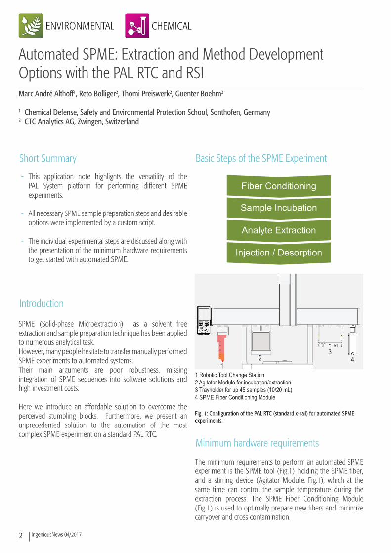
Basic Steps of the SPME Experiment
Minimum hardware requirements
The minimum requirements to perform an automated SPME experiment is the SPME tool (Fig.1) holding the SPME fiber, and a stirring device (Agitator Module, Fig.1), which at the same time can control the sample temperature during the extraction process. The SPME Fiber Conditioning Module (Fig.1) is used to optimally prepare new fibers and minimize carryover and cross contamination.
Fig. 1: Configuration of the PAL RTC (standard x-rail) for automated SPME experiments.
1 Robotic Tool Change Station2 Agitator Module for incubation/extraction3 Trayholder for up 45 samples (10/20 mL)4 SPME Fiber Conditioning Module
12
34
Fiber Conditioning
Sample Incubation
Analyte Extraction
Injection / Desorption
3IngeniousNews 04/2017
The automated exchange of tools possible with the Robotic Tool Change Station allows an automated workflow in the processing of SPME (e.g. automatic exchange of fibers, or screening of fibers) and experiments with other tools such as headspace or standard liquid injections.
The advanced SPME experiment and method development steps
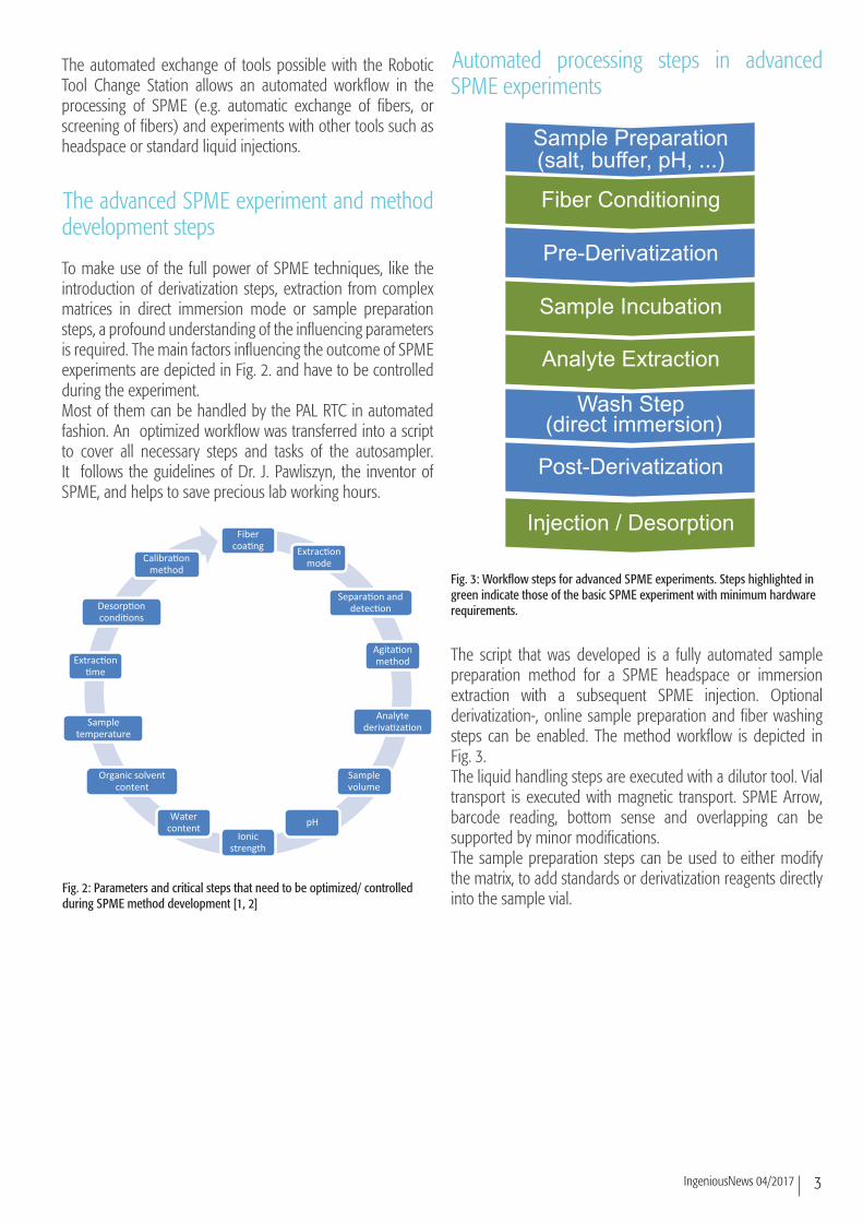
To make use of the full power of SPME techniques, like the introduction of derivatization steps, extraction from complex matrices in direct immersion mode or sample preparation steps, a profound understanding of the influencing parameters is required. The main factors influencing the outcome of SPME experiments are depicted in Fig. 2. and have to be controlled during the experiment.Most of them can be handled by the PAL RTC in automated fashion. An optimized workflow was transferred into a script to cover all necessary steps and tasks of the autosampler. It follows the guidelines of Dr. J. Pawliszyn, the inventor of SPME, and helps to save precious lab working hours.
Automated processing steps in advanced SPME experiments
The script that was developed is a fully automated sample preparation method for a SPME headspace or immersion extraction with a subsequent SPME injection. Optional derivatization-, online sample preparation and fiber washing steps can be enabled. The method workflow is depicted in Fig. 3. The liquid handling steps are executed with a dilutor tool. Vial transport is executed with magnetic transport. SPME Arrow, barcode reading, bottom sense and overlapping can be supported by minor modifications.The sample preparation steps can be used to either modify the matrix, to add standards or derivatization reagents directly into the sample vial.
Fig. 3: Workflow steps for advanced SPME experiments. Steps highlighted in green indicate those of the basic SPME experiment with minimum hardware requirements.
Fig. 2: Parameters and critical steps that need to be optimized/ controlled during SPME method development [1, 2]
Fiber coa�ng Extrac�on
mode
Separa�on and detec�on
Agita�on method
Analyte deriva�za�on
Sample volume
pHIonic
strength
Water content
Organic solvent content
Sample temperature
Extrac�on �me
Desorp�on condi�ons
Calibra�on method
Sample Preparation(salt, buffer, pH, ...)
Fiber Conditioning
Pre-Derivatization
Sample Incubation
Analyte Extraction
Wash Step (direct immersion)
Post-Derivatization
Injection / Desorption
4 IngeniousNews 04/2017
Automated processing steps in advanced SPME experiments (continued)
The numerous options to use derivatization reagents within the SPME experiment are all covered within the developed script. However, on fiber (pre and post of the injection or both) and in vial derivatization require additional equipment.In case of complex matrices containing, e.g. pulp, fiber or sugar it is most convenient to employ over-coted SPME fibers and to add a wash step prior to the injection in order to avoid the baking of those matrices on the fiber and enhance its lifetime. In the developed script a Fast Wash Module is used for an optional SPME fiber wash step following sample extraction. Here, the fiber can be exposed into a flushing solvent (usually water) for a short period of time. It is not recommended to use other wash modules since cross contamination may occur.
Hardware for advanced SPME experiments
With the basic hardware setup for automated SPME experiments (Fig 1.) all steps of a SPME experiment can be
performed. A PAL RTC or RSI according to Fig. 1 comprises the following tools and modules:
- Trayholder (for samples) - SPME Tool (or SPME Arrow Tool) - SPME (Arrow) Conditioning Module - Agitator Module
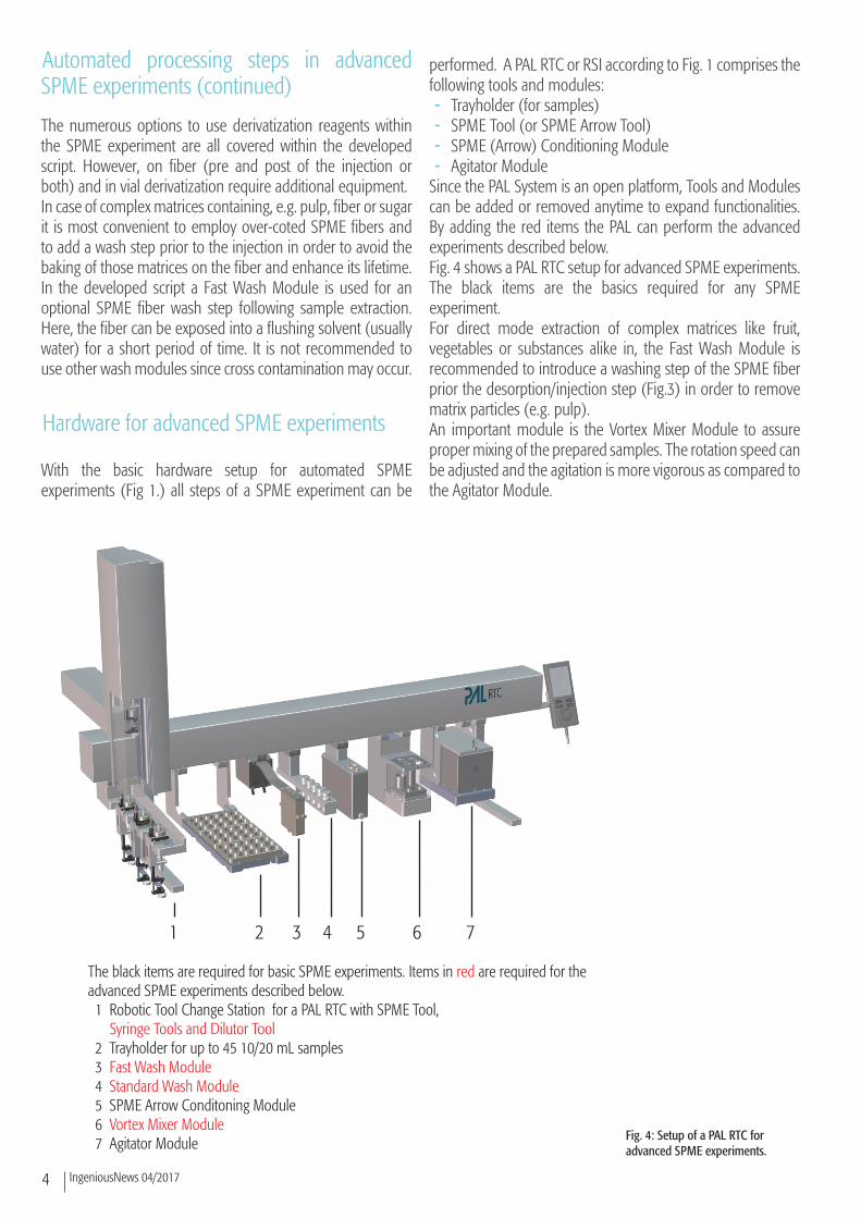
Since the PAL System is an open platform, Tools and Modules can be added or removed anytime to expand functionalities. By adding the red items the PAL can perform the advanced experiments described below. Fig. 4 shows a PAL RTC setup for advanced SPME experiments. The black items are the basics required for any SPME experiment. For direct mode extraction of complex matrices like fruit, vegetables or substances alike in, the Fast Wash Module is recommended to introduce a washing step of the SPME fiber prior the desorption/injection step (Fig.3) in order to remove matrix particles (e.g. pulp).An important module is the Vortex Mixer Module to assure proper mixing of the prepared samples. The rotation speed can be adjusted and the agitation is more vigorous as compared to the Agitator Module.
Fig. 4: Setup of a PAL RTC for advanced SPME experiments.
1 2 3 4 5 6 7
The black items are required for basic SPME experiments. Items in red are required for theadvanced SPME experiments described below. 1 Robotic Tool Change Station for a PAL RTC with SPME Tool, Syringe Tools and Dilutor Tool 2 Trayholder for up to 45 10/20 mL samples 3 Fast Wash Module 4 Standard Wash Module 5 SPME Arrow Conditoning Module 6 Vortex Mixer Module 7 Agitator Module

5IngeniousNews 04/2017
Hardware for advanced SPME experiments continued
The Dilutor Tool is essential in automated workflows for SPME method development experiments when it comes to sample preparation steps. It dispenses liquids from up to 4 different sources, e.g. to adjust the pH or salt concentration in the sam-ple. Furthermore, it can be used to dilute samples, prepare calibration curves for liquid injections or to transfer derivatiza-tion agents. Besides delivering larger volumes (Fig. 5) of liquids the Di-lutor can also be used to transfer small volumes with good precision applying the “Transfer Mode”.
Advanced scripting
To make use of the numerous options of the hardware mod-ules it is necessary to integrate the parameters in the respec-tive instrument software. In the present case Chromeleon 7.2 (Thermo Fisher Scientific) was used to execute experiments.The script is a fully automated sample preparation method for a SPME headspace or direct immersion extraction with a subsequent SPME injection. Optional derivatization-, online sample preparation and fiber washing steps can be enabled.The availability of that many options and adjustable parame-ters in a single script is unprecedented and offers almost un-limited flexibility to the (advanced) user. Fig. 6 is shows the user inferace within Chromeleon 7.2 software.The sample preparation workflow is shown in Fig. 7 (next page) and follows the automated processing steps illustrated in Fig. 3. By disabling the transparent fields it represents the same steps as in the basic SPME method.Users only have to place the necessary sampling vials manu-ally on the sampling tray of the autosampler and set up the experiments by filling out the fields of the graphical user inter-face shown in Fig. 6.
Application example
A first application example of this script can be found in a recent article [3]. It has to be noted that these results were obtained with the basic SPME equipment as depicted in Fig. 1. None of the additional options were used.The aim of the study was the development of a direct im-mersion SPME experiment and to compare it to a headspace extraction method. Pesticide-like organothiophosphates close-ly related to compounds covered in the Chemical Weapons Convention (CWC) [4] were chosen as analytes. The sampling matrices were different water and vegetation samples (foliage and grass). Various influencing parameters, e.g. salt addition and pH-value of the samples were investigated.For the first time, it could be shown that direct immersion
SPME from complex matrices is a suitable technique for the fast and reliable detection and analysis of different organo-phosphates closely related to the CWC.
Fig. 5: Depiction of the Dilutor Tool/Module in Delivery Mode (for large volumes) and below in Transfer Mode (for small volumes).
Fig.6: Screenshot from Chromeleon Software of some of the parameters that can be adjusted by the user by using the developed SPME script for the TriPlus RSH autosampler.
6 IngeniousNews 04/2017
In terms of sensitivity it is superior to head space SPME. Fur-thermore, LOD and LOQ levels in the low μg/mL range could be achieved.
Fiber type 65 μm PDMS/DVB, length: 1 cm(blue hub plain, 24 gauge)
Extraction time 3.0 min - 10.0 min (DI) / 30.0 min (HS)
Extraction temperature 20°C / 40°C / 60°C / 80°C
Sample matrices sea sand, grass, foliage, tap water, phosphate buffer solution
Phosphate buffer pH 4.00, 6.88, 9.22
Glimpse behind-the-scenes
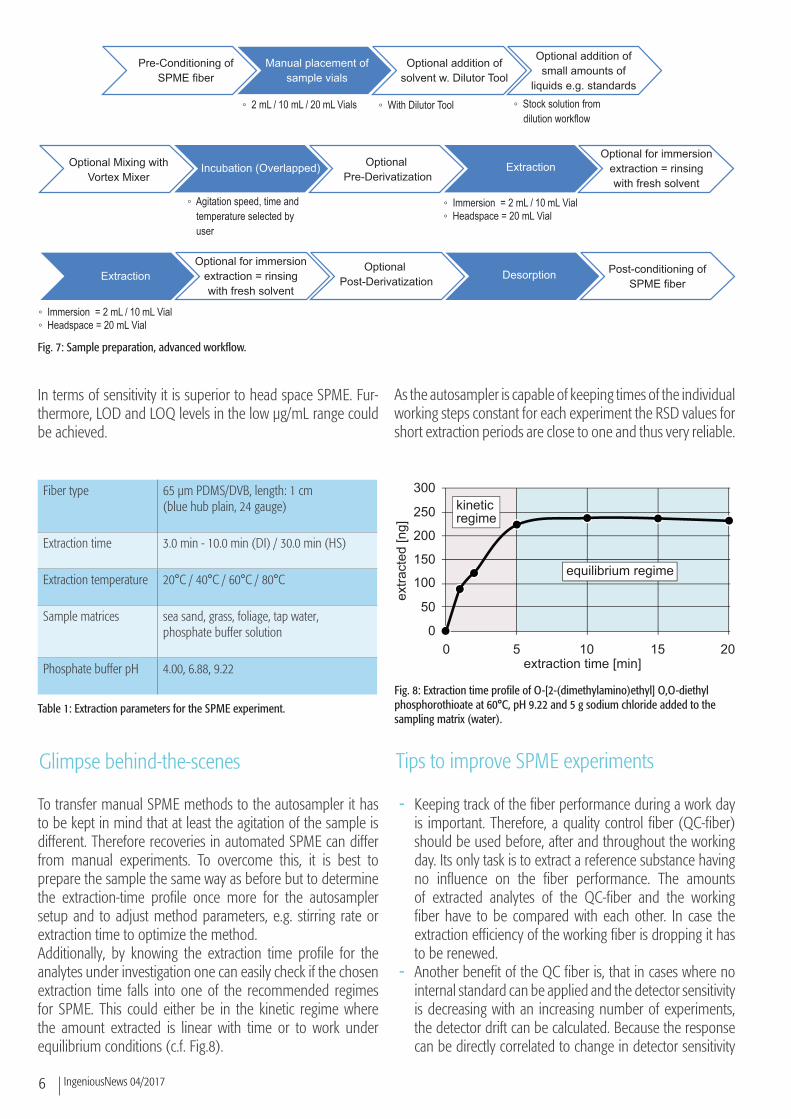
To transfer manual SPME methods to the autosampler it has to be kept in mind that at least the agitation of the sample is different. Therefore recoveries in automated SPME can differ from manual experiments. To overcome this, it is best to prepare the sample the same way as before but to determine the extraction-time profile once more for the autosampler setup and to adjust method parameters, e.g. stirring rate or extraction time to optimize the method.Additionally, by knowing the extraction time profile for the analytes under investigation one can easily check if the chosen extraction time falls into one of the recommended regimes for SPME. This could either be in the kinetic regime where the amount extracted is linear with time or to work under equilibrium conditions (c.f. Fig.8).
As the autosampler is capable of keeping times of the individual working steps constant for each experiment the RSD values for short extraction periods are close to one and thus very reliable.
Tips to improve SPME experiments
- Keeping track of the fiber performance during a work day is important. Therefore, a quality control fiber (QC-fiber) should be used before, after and throughout the working day. Its only task is to extract a reference substance having no influence on the fiber performance. The amounts of extracted analytes of the QC-fiber and the working fiber have to be compared with each other. In case the extraction efficiency of the working fiber is dropping it has to be renewed.
- Another benefit of the QC fiber is, that in cases where no internal standard can be applied and the detector sensitivity is decreasing with an increasing number of experiments, the detector drift can be calculated. Because the response can be directly correlated to change in detector sensitivity
Pre-Conditioning ofSPME fiber
Manual placement ofsample vials
Optional addition ofsolvent w. Dilutor Tool
Optional addition ofsmall amounts of
liquids e.g. standards
Optional Mixing withVortex Mixer
Incubation (Overlapped) Optional Pre-Derivatization
Optional for immersionextraction = rinsingwith fresh solvent
Extraction
Extraction Desorption Post-conditioning ofSPME fiber
Optional for immersionextraction = rinsingwith fresh solvent
Optional Post-Derivatization
◦ 2 mL / 10 mL / 20 mL Vials ◦ With Dilutor Tool ◦ Stock solution fromdilution workflow
◦ Agitation speed, time andtemperature selected byuser
◦ Immersion = 2 mL / 10 mL Vial◦ Headspace = 20 mL Vial
◦ Immersion = 2 mL / 10 mL Vial◦ Headspace = 20 mL Vial
Table 1: Extraction parameters for the SPME experiment.
0 5 10 15 20extraction time [min]
extra
cted
[ng]
0
50
100
150
200
250
300
equilibrium regime
kineticregime
Fig. 8: Extraction time profile of O-[2-(dimethylamino)ethyl] O,O-diethyl phosphorothioate at 60°C, pH 9.22 and 5 g sodium chloride added to the sampling matrix (water).
Fig. 7: Sample preparation, advanced workflow.

7IngeniousNews 04/2017
a correction factor can be determined and applied to the obtained results.
- With the availability of the Robotic Tool Change (RTC) the QC fiber can be easily mounted in a second SPME Tool and is ready for use at any point of time in the sample list.
- The proper presentation of SPME data can be very challenging to new users of this technique. In terms of quantifiable results one should always report the nanogram-amount extracted by the SPME fiber. These numbers can be obtained by the measurement of a calibration curve of a liquid injection. Here the number of moles injected into the system is known very precisely. A plot of ng injected versus peak area should result in a linear regression curve.
Hardware requirements
- The Standard- or Large Wash Module can be used as a reservoir for the analyte solution used in the online sample prep. The waste position is used for all dilutor priming and purge steps since the septa in this waste port strips off droplets from the needle. Thereby carry over can be reduced.
- All vials must be equipped with magnetic caps. - In case of a system reset, the remaining liquid present in
the dilutor syringe is ejected to port 2 at the dilutor valve. It is recommended to connect a waste container to this dilutor valve port.
- It’s important to prime the dilutor in a particular sequence to avoid contact of immiscible solvents or solutions. To prime the dilutor the dilutor tool must be coupled in the PAL Head.
Software requirements
The method has been implemented with: - Firmware 2.3.16102.1502 (for Thermo Scientific TriPlus RSH) - Chromeleon 7.2 SR4 MUb / Patch Files for PAL FW 2.3
AcknowledgementThe first author of this application note is very thankful to Prof. J. Pawliszyn for offering the chance to visit his labs at the University of Waterloo, ON, Canada and receiving an in-depth training on SPME from the inventor of this technique as well as reviewing this article.
References
[1] Risticevic, S.; Lord, H.; Gorecki, T.; Arthur, C. L.; Pawliszyn, J., Protocol for solid-phase microextraction method development. Nat. Protocols 2010, 5 (1), 122-139.
[2] Pawliszyn, J., Handbook of Solid-Phase Microextraction, Elsevier, 2011.
[3] Althoff, M.A.; Bertsch, A.; Metzulat, M.; Klapötke, T.M.; Karaghiosoff, K.L. Application of Headspace and Direct Immersion Solid-Phase Microextraction in the Analysis of Organothiophosphates related to the Chemical Weapons Convention from Water and Complex Matrices . Talanta, 2017, 174, 295-300.
[4] OPCW, Convention on the Prohibition of the Development, Production, Stockpiling and Use of Chemical Weapons and on Their Destruction. 1997: OPCW.

Imprint
Date of print: 12.2017
CTC Analytics AGIndustriestrasse 20CH-4222 ZwingenSwitzerland T +41 61 765 81 00Contact: [email protected]
Legal Statements
CTC Analytics AG reserves the right to make improvements and/or changes to the product(s) described in this document at any time without prior notice.
CTC Analytics AG makes no warranty of any kind pertaining to this product, including but not limited to implied warranties of merchantability and suitability for a particular purpose.
Under no circumstances shall CTC Analytics AG be held liable for any coincidental damage or damages arising as a consequence of or from the use of this document.
© 2017 CTC Analytics AG. All rights reserved. Neither this publication nor any part hereof may be copied, photocopied, reproduced, translated, distributed or reduced to electronic medium or machine readable form without the prior written permission from CTC Analytics AG, except as permitted under copyright laws.
CTC Analytics AG acknowledges all trade names and trademarks used as the property of their respective owners.
PAL is a registered trademark of CTC Analytics AG | Switzerland
www.palsystem.comVisit our homepage for more information.