Embed Size (px)
Citation preview
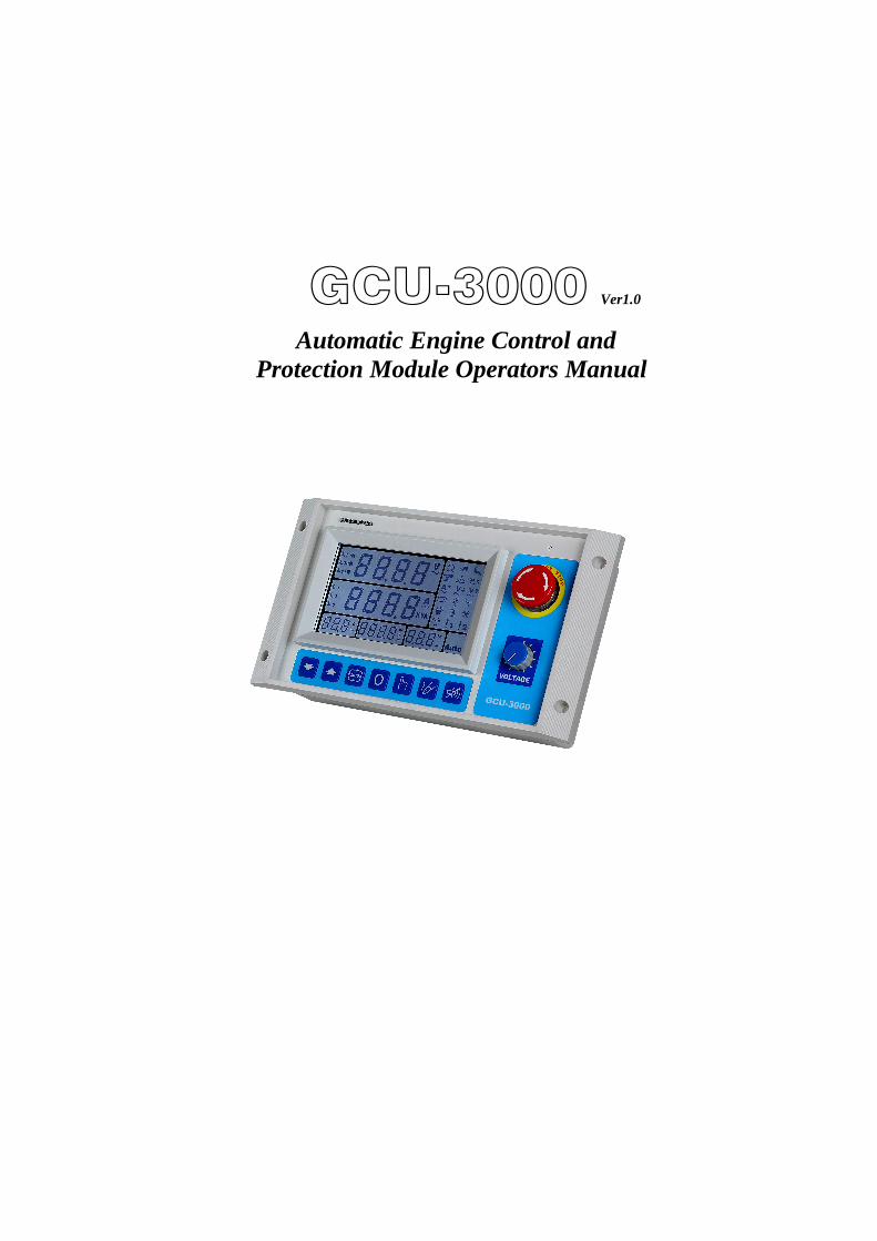
GCU-3000 Ver1.0 Automatic Engine Control and
Protection Module Operators Manual
GCU-3000 Automatic Engine Control and Protection Module
______________________________________________________________________________________
2
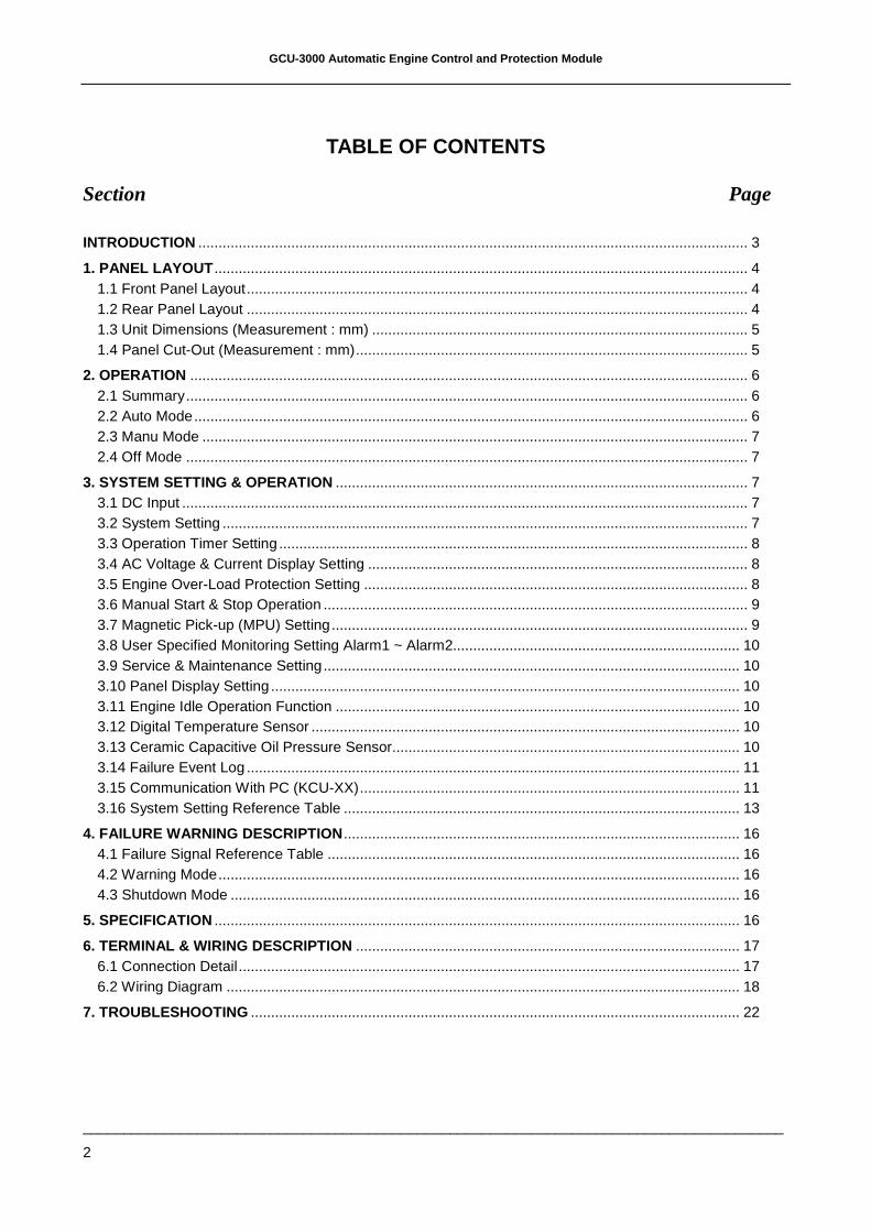
TABLE OF CONTENTS
Section Page
INTRODUCTION ........................................................................................................................................ 3
1. PANEL LAYOUT .................................................................................................................................... 4 1.1 Front Panel Layout............................................................................................................................ 4 1.2 Rear Panel Layout ............................................................................................................................ 4 1.3 Unit Dimensions (Measurement : mm) ............................................................................................. 5 1.4 Panel Cut-Out (Measurement : mm)................................................................................................. 5
2. OPERATION .......................................................................................................................................... 6 2.1 Summary........................................................................................................................................... 6 2.2 Auto Mode......................................................................................................................................... 6 2.3 Manu Mode ....................................................................................................................................... 7 2.4 Off Mode ........................................................................................................................................... 7
3. SYSTEM SETTING & OPERATION ...................................................................................................... 7 3.1 DC Input ............................................................................................................................................ 7 3.2 System Setting .................................................................................................................................. 7 3.3 Operation Timer Setting .................................................................................................................... 8 3.4 AC Voltage & Current Display Setting .............................................................................................. 8 3.5 Engine Over-Load Protection Setting ............................................................................................... 8 3.6 Manual Start & Stop Operation ......................................................................................................... 9 3.7 Magnetic Pick-up (MPU) Setting....................................................................................................... 9 3.8 User Specified Monitoring Setting Alarm1 ~ Alarm2....................................................................... 10 3.9 Service & Maintenance Setting....................................................................................................... 10 3.10 Panel Display Setting .................................................................................................................... 10 3.11 Engine Idle Operation Function .................................................................................................... 10 3.12 Digital Temperature Sensor .......................................................................................................... 10 3.13 Ceramic Capacitive Oil Pressure Sensor...................................................................................... 10 3.14 Failure Event Log .......................................................................................................................... 11 3.15 Communication With PC (KCU-XX).............................................................................................. 11 3.16 System Setting Reference Table .................................................................................................. 13
4. FAILURE WARNING DESCRIPTION .................................................................................................. 16 4.1 Failure Signal Reference Table ...................................................................................................... 16 4.2 Warning Mode................................................................................................................................. 16 4.3 Shutdown Mode .............................................................................................................................. 16
5. SPECIFICATION .................................................................................................................................. 16
6. TERMINAL & WIRING DESCRIPTION ............................................................................................... 17 6.1 Connection Detail............................................................................................................................ 17 6.2 Wiring Diagram ............................................................................................................................... 18
7. TROUBLESHOOTING ......................................................................................................................... 22
GCU-3000 Automatic Engine Control and Protection Module
______________________________________________________________________________________
3
INTRODUCTION The GCU-3000 is an integrated modular design Automatic Engine Control Protection Module quipped with the largest LCD display screen compare to most available engine controllers on the market. It is suitable for use on all conventional genset applications. The user friendly interface with easy to recognize warning icons and powerful functions to provide complete protection to the generators. Overall, the GCU-3000 pushes the definition of genset control protection to a whole new perspective.
The customer can program the GCU-3000 directly from the front panel without using a computer. Any new settings are recorded into the internal (EEPROM) and protected from erasure even without battery.
GCU-3000 is operated via 3 selectable operation modes, the automatic mode (AUTO), the manual mode (MANU) and the engine shutdown mode. The main features includes the followings
:
Integrated modular panel design
Large LCD display screen for instantaneous information display
Programmable repetition engine start
Programmable engine idle speed timer
Programmable engine cool down
Programmable maintenance notification
Engine standby space heater control
Digital temperature sensor
High precision oil pressure sensor
Full coverage of monitoring and protection
LCD screen display entry of instantaneous readings and information includes the following
:
Full phase AC phase voltage
Full phase AC line voltage
Full phase load current
Kilovolt ampere reading
AC frequency
Engine operating hour
Battery DC voltage
Oil pressure (Unit:
Psi or Bar)
Operating temperature (Unit: or )
Failure Warning icon display
Other than displaying selected fixed readings, the GCU-3000 can also allow cycling value display, enables user to obtain cycling repetition of all readings in a 2 sec succession.
The integrated modular design includes a front panel emergency stop button and built in potentiometer (VR) to allow users to carry out voltage adjustment on the Automatic Voltage Regulators (AVR) directly from the GCU-3000. Also it is equipped with full phase AC and DC voltage protection fuse to ensure system operation safely.
When generator failure occurs and engine stops. The built in warning buzzer will announce along with LCD warning display on the front panel. In the same time provide a remote failure warning signal to the distant location or operation room for monitoring use and to warn the operator or maintenance personnel. GCU-3000 is equipped with built in Failure Event Log program, that records up to 15 sets failure event logs. When a failure occurs the system automatically records the failure status and time of the event it records the failure status and time. All failure record can be read directly from the panel.
We have taken the lead to add the space heating function into the GCU-3000. With the constant temperature ability added. The generator is then able to maintain smooth and superior engine start even in the coldest weather.
GCU-3000 Monitoring and Protection:
High Engine Temperature Protection
Low Engine Oil Pressure Protection
Engine Over & Under Speed Protection
Full Phase AC Over & Under Voltage and missing phase Monitoring
Full Phase Load Current Monitoring
Battery Over & Under Voltage Monitoring
Low Fuel Level Monitoring
Temperature & Pressure Sensor Failure
Magnetic Pickup (MPU) Failure
The GCU-3000 also reserves 2 user defined warning signal inputs. This allows the user to freely plan out the preferred monitoring subject other than the already provided.
GCU-3000 Automatic Engine Control and Protection Module
______________________________________________________________________________________
4
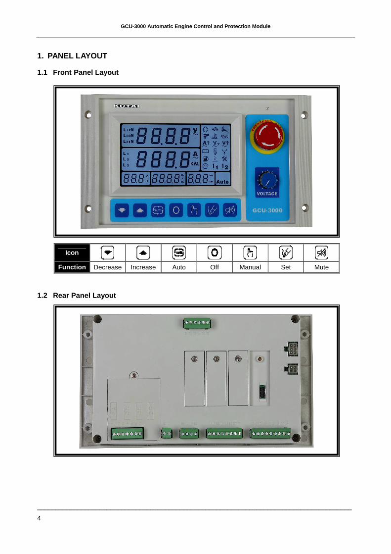
1. PANEL LAYOUT
1.1 Front Panel Layout
1.2 Rear Panel Layout
Icon
Function Decrease Increase Auto Off Manual Set Mute
GCU-3000 Automatic Engine Control and Protection Module
______________________________________________________________________________________
5
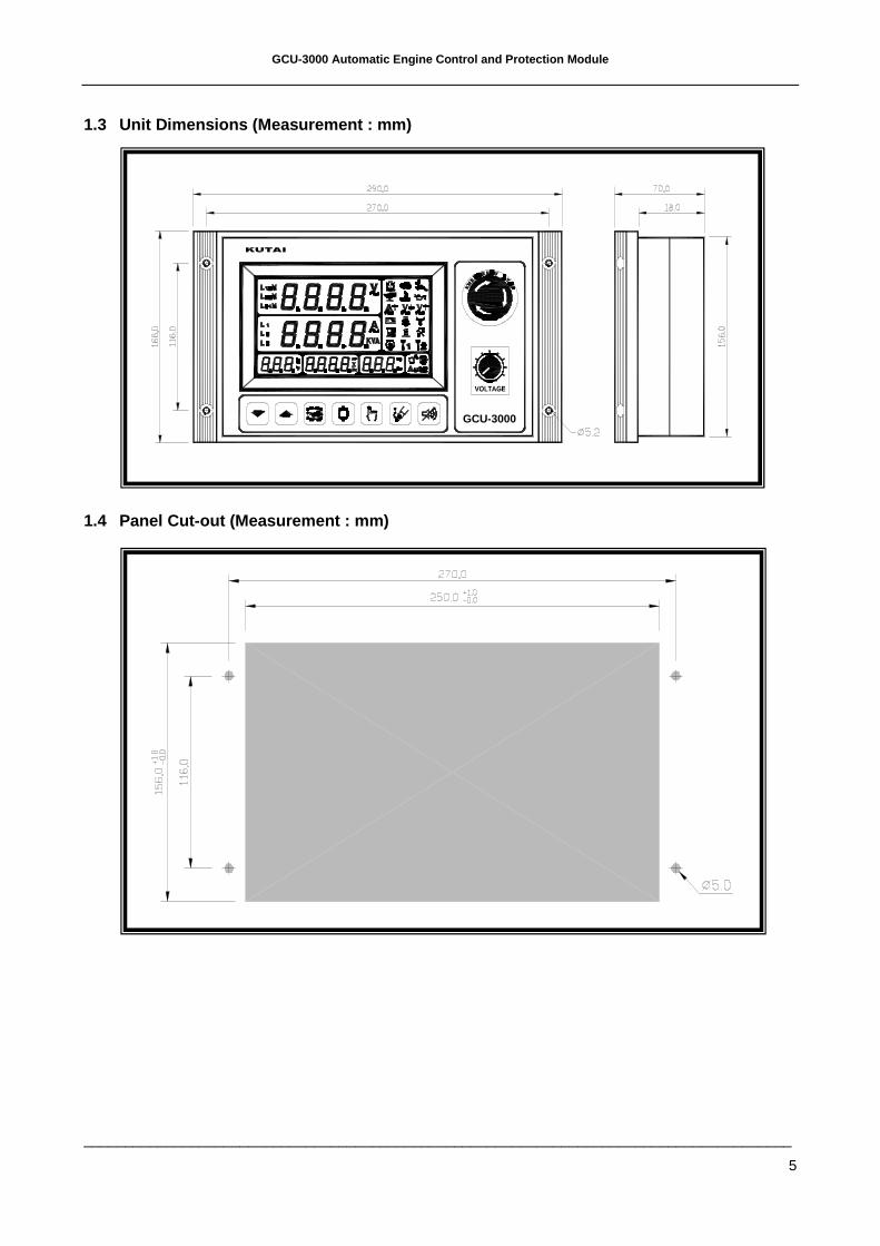
1.3 Unit Dimensions (Measurement : mm)
1.4 Panel Cut-out (Measurement : mm)
GCU-2000
GCU-3000
GCU-3000 Automatic Engine Control and Protection Module
______________________________________________________________________________________
6
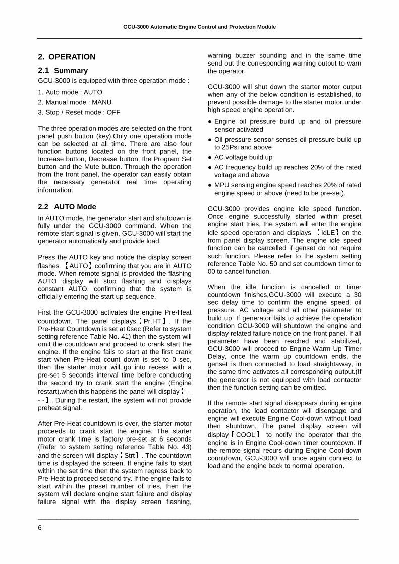
2. OPERATION
2.1 Summary GCU-3000 is equipped with three operation mode :
1. Auto mode : AUTO
2. Manual mode : MANU
3. Stop / Reset mode : OFF
The three operation modes are selected on the front panel push button (key).Only one operation mode can be selected at all time. There are also four function buttons located on the front panel, the Increase button, Decrease button, the Program Set button and the Mute button. Through the operation from the front panel, the operator can easily obtain the necessary generator real time operating information.
2.2 AUTO Mode
In AUTO mode, the generator start and shutdown is fully under the GCU-3000 command. When the remote start signal is given, GCU-3000 will start the generator automatically and provide load.
Press the AUTO key and notice the display screen flashes
【AUTO】confirming that you are in AUTO
mode. When remote signal is provided the flashing AUTO display will stop flashing and displays constant AUTO, confirming that the system is officially entering the start up sequence.
First the GCU-3000 activates the engine Pre-Heat countdown. The panel displays
【Pr.HT】. If the
Pre-Heat Countdown is set at 0sec (Refer to system setting reference Table No. 41) then the system will omit the countdown and proceed to crank start the engine. If the engine fails to start at the first crank start when Pre-Heat count down is set to 0 sec, then the starter motor will go into recess with a pre-set 5 seconds interval time before conducting the second try to crank start the engine (Engine restart).when this happens the panel will display
【- -
- -】. During the restart, the system will not provide preheat signal.
After Pre-Heat countdown is over, the starter motor proceeds to crank start the engine. The starter motor crank time is factory pre-set at 6 seconds (Refer to system setting reference Table No. 43) and the screen will display
【Strt】. The countdown
time is displayed the screen. If engine fails to start within the set time then the system regress back to Pre-Heat to proceed second try. If the engine fails to start within the preset number of tries, then the system will declare engine start failure and display failure signal with the display screen flashing,
warning buzzer sounding and in the same time send out the corresponding warning output to warn the operator.
GCU-3000 will shut down the starter motor output when any of the below condition is established, to prevent possible damage to the starter motor under high speed engine operation.
Engine oil pressure build up and oil pressure sensor activated
Oil pressure sensor senses oil pressure build up to 25Psi and above
AC voltage build up
AC frequency build up reaches 20% of the rated voltage and above
MPU sensing engine speed reaches 20% of rated engine speed or above (need to be pre-set).
GCU-3000 provides engine idle speed function. Once engine successfully started within preset engine start tries, the system will enter the engine idle speed operation and displays
【IdLE】on the
from panel display screen. The engine idle speed function can be cancelled if genset do not require such function. Please refer to the system setting reference Table No. 50 and set countdown timer to 00 to cancel function.
When the idle function is cancelled or timer countdown finishes,GCU-3000 will execute a 30 sec delay time to confirm the engine speed, oil pressure, AC voltage and all other parameter to build up. If generator fails to achieve the operation condition GCU-3000 will shutdown the engine and display related failure notice on the front panel. If all parameter have been reached and stabilized, GCU-3000 will proceed to Engine Warm Up Timer Delay, once the warm up countdown ends, the genset is then connected to load straightaway, in the same time activates all corresponding output.(If the generator is not equipped with load contactor then the function setting can be omitted.
If the remote start signal disappears during engine operation, the load contactor will disengage and engine will execute Engine Cool-down without load then shutdown, The panel display screen will display
【COOL】 to notify the operator that the
engine is in Engine Cool-down timer countdown. If the remote signal recurs during Engine Cool-down countdown, GCU-3000 will once again connect to load and the engine back to normal operation.
GCU-3000 Automatic Engine Control and Protection Module
______________________________________________________________________________________
7
Once the Engine Cool-down countdown ends,GCU-3000 will then execute engine stop countdown timer and stop the engine according to user setting to energize to start or energize to stop. The front panel display screen will display
【Stop】.
ATTENTION
When the generator is on Engine Cool-down the AMF-10 protection system remains in effect and if any failure occurs, the module bypasses the countdown and shutdown generator immediately.
2.3 MANUAL Mode
In MANU (manual) mode, operator is allowed to manually start and stop the generator. After the generator successfully started the engine, GCU-3000 will automatically connect to load. When switch over to
【OFF】or
【AUTO】mode the
generator will proceed normal procedure to shut down the generator.
Under manual mode, engine start and stop procedure is the same as in auto mode.
2.4 OFF Mode
OFF mode represents a shut down condition or failure reset mode. If
【OFF】mode is selected during
normal genset operation, the generator will proceed normal procedure to shut down the generator. the load contactor will disengage and engine will execute Engine Cool-down without load then shutdown.
If the system senses a major failure occurring during the normal operation, it will immediately shutdown the genset to prevent greater damage or injury. After the engine comes to a complete stop, the failure notice will displayed on the display screen. The service personnel can conduct service and repair according to the failure notice. If there are more than two cause of failure, all of the failure notice will be displayed on the display screen in the same time. By switching to the OFF mode, the failure notice will be erased from the panel screen.
3. SYSTEM SETTING & OPERATION
ATTENTION
Before proceeding the GCU-3000 system setting, user must first correctly install all the connection wirings and connect the Battery DC input. Please refer to chapter 1.1 Front Panel Layout for input key representation.
3.1 DC Input
GCU-3000 allows wide range of operating power inputs from 9~36VDC, incorrect DC voltage input will not cause damage to the module.
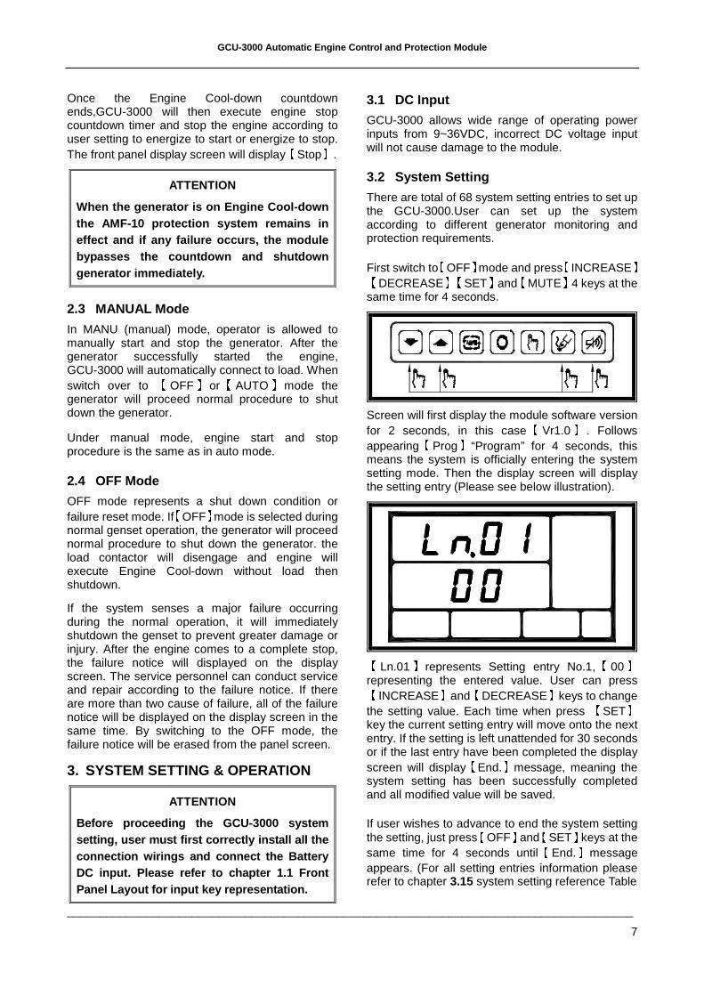
3.2 System Setting There are total of 68 system setting entries to set up the GCU-3000.User can set up the system according to different generator monitoring and protection requirements.
First switch to【
OFF】mode and press【
INCREASE】【DECREASE】【SET】and
【MUTE】4 keys at the
same time for 4 seconds.
Screen will first display the module software version for 2 seconds, in this case
【Vr1.0】 . Follows
appearing【
Prog】“Program” for 4 seconds, this means the system is officially entering the system setting mode. Then the display screen will display the setting entry (Please see below illustration).
【Ln.01】represents Setting entry No.1,
【00】
representing the entered value. User can press【INCREASE】and
【DECREASE】keys to change
the setting value. Each time when press 【
SET】 key the current setting entry will move onto the next entry. If the setting is left unattended for 30 seconds or if the last entry have been completed the display screen will display
【End.】message, meaning the
system setting has been successfully completed and all modified value will be saved.
If user wishes to advance to end the system setting the setting, just press
【OFF】and
【SET】keys at the
same time for 4 seconds until【
End.】message appears. (For all setting entries information please refer to chapter 3.15 system setting reference Table
GCU-3000 Automatic Engine Control and Protection Module
______________________________________________________________________________________
8
GCU-3000 is preset with factory setting when manufactured, if user wishes to restore the original factory setting, just press
【AUTO】and
【SET】keys
for 4 seconds until “Au.PO” message appears, meaning the factory setting has been restored.
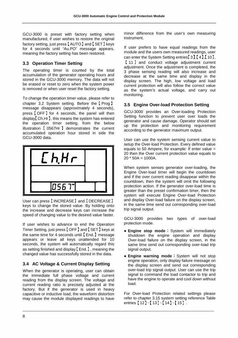
3.3 Operation Timer Setting
The operating timer is counted by the total accumulation of the generator operating hours and stored in the GCU-3000 memory. The data will not be erased or reset to zero when the system power is removed or when user reset the factory setting.
To change the operation timer value, please refer to chapter 3.2 System setting. Before the
【Prog】
message disappears (approximately 4 seconds), press
【OFF】for 4 seconds, the panel will then
display【
Ch.Hr】, this means the system has entered the operation timer setting, from the below illustration
【0567Hr 】 demonstrates the current
accumulated operation hour stored in side the GCU-3000 data.
User can press【
INCREASE】and【
DECREASE】keys to change the stored value. By holding onto the increase and decrease keys can increase the speed of changing value to the desired value faster.
If user wishes to advance to end the Operation Timer Setting, just press
【OFF】and
【SET】keys at
the same time for 4 seconds until【
End.】message appears or leave all keys unattended for 10 seconds, the system will automatically regard this as setting finished and display
【End.】, meaning the
changed value has successfully stored in the data.
3.4 AC Voltage & Current Display Setting
When the generator is operating, user can obtain the immediate full phase voltage and current reading from the display screen. The voltage and current reading ratio is precisely adjusted at the factory. But if the generator is used in heavy capacitive or inductive load, the waveform distortion may cause the module displayed readings to have
minor difference from the user’s own measuring instrument.
If user prefers to have equal readings from the module and the users own measured readings, user can enter the System Setting entries
【3】,【4】,【10】,【
11】and conduct voltage adjustment current adjustment. Once the adjustment is completed, the 3 phase sensing reading will also increase and decrease at the same time and display in the display screen. The high, low voltage and load current protection will also follow the correct value as the system’s actual voltage, and carry out monitoring.
3.5 Engine Over-load Protection Setting
GCU-3000 provides an Over-loading Protection Setting function to prevent user over loads the generator and cause damage. Operator should set up the protection and monitoring requirement according to the generator maximum output.
User can use the system sensing current value to setup the Over-load Protection. Every defined value equals to 50 Ampere, for example: If enter value = 20 then the Over current protection value equals to 20 * 50A = 1000A.
When system senses generator over-loading, the Engine Over-load timer will begin the countdown and if the over current reading disappear within the countdown, then the system will omit the following protection action. If the generator over-load time is greater than the preset confirmation timer, then the system will execute Engine Over-load Protection and display Over-load failure on the display screen, in the same time send out corresponding over-load trip signal output.
GCU-3000 provides two types of over-load protection mode.
Engine stop mode::::
System will immediately shutdown the engine operation and display Over-load failure on the display screen, in the same time send out corresponding over-load trip signal output.
Engine warning mode::::
System will not stop engine operation, only display failure message on the display screen and send out corresponding over-load trip signal output. User can use the trip signal to command the load contactor to trip and have the engine to operate and cool down without load.
For Over-load Protection related settings please refer to chapter 3.15 system setting reference Table entries
【12】、【13】、【14】、【15】.
GCU-3000 Automatic Engine Control and Protection Module
______________________________________________________________________________________
9
ATTENTION
When using GCU-3000 sensing current reading as the over-load protection value, user needs to pay special attention to the setting of the over-load current value as it can not exceed the CT primary rated value, other wise the field saturation can cause the system fail to obtain correct current reading and loose the Over-load Protection function.
For example::::
If CT ratio is 1000A : 5A, then over current setting can only set up to 1000A.
3.6 Manual Start & Stop Operation
Under normal operation, operator can start up the engine via the front panel operation key or from a remote signal. When any abnormality occurs during operation, the system will interfere and enforce engine stop in the same time activate the alarm output and display corresponding failure message and icon on the display screen.
Manual Start & Stop Operation mode is used to manually start and stop the newly assembled genset, and program and adjust the AC voltage and engine speed to the rated setting.
Before entering Manual Start & Stop Operation mode, operator should complete all wiring connections and step by step check and confirm the GCU-3000 system setting. When completed, please enter system setting entry
【67】and select Manual
start and stop operation mode.
Under Manual Start & Stop Operation mode, display screen manual mode icon will appear to notify the operating status. To start up the generator to proceed voltage and engine speed adjustment, please press the
【MANU】key on the front panel until
the engine is fired up, release the key to stop the starter motor. To stop the generator operation, press
【AUTO】key until the engine comes to a
complete stop.
Once the setting is completed, operator should reset the system back to normal operation. The operator do not need to enter system setting to change the operation, just press
【OFF】key, the
GCU-3000 will stop the generator according to system setting and automatically reset to normal operation mode.
For Manual Start & Stop Operation mode related settings please refer to chapter 3.15 System Setting Reference Table entries
【67】.
ATTENTION
Under manual operation,GCU-3000 will cancel all automatic protections, meaning if a failure occurs while in manual operation, the system will not automatically shutdown the engine. So it is strongly advised that manual operation is suitable for preliminary adjustment use only.
3.7 Magnetic Pick-up (MPU) Setting
MPU (Magnetic Pick-up) is the magnetic sensing device installed on the flywheel case. It detects the engine revolution according to the frequency measured on flywheel gear by the seconds. Most generators with electronics speed controllers / governors are equipped with it.
MPU rated frequency range:
100Hz ~ 10K Hz
To setup the MPU frequency, please enter manual mode. Manually start the engine to the rated speed (50Hz or 60Hz),Press
【SET】key, the system will
display and begin to read the current MPU frequency, after the reading is completed, the display screen will display
【Au.Po 】message,
confirming the setting is completed.
If the system detects the MPU frequency is below 100Hz,then it will consider it as MPU failure and display
【FAIL】message on the display screen, in the
same time the MPU signal failure iconwill appear on the display screen, confirming a setting procedure failure. At this point operator should first check for MPU failure, incorrect wiring or bad contact. Repeat the setup procedure after the cause of failure has be identified and cleared.
If the system detects the MPU frequency is above 10KHz, then it will consider it as MPU failure and display
【FAIL】message on the display screen, in
the same time the Engine Over speed failure icon will appear on the display screen, confirming a setting procedure failure. At this point operator should first check for MPU failure, incorrect wiring or bad contact. Repeat the setup procedure after the cause of failure has be identified and cleared.
GCU-3000 Automatic Engine Control and Protection Module
______________________________________________________________________________________
10
Some Electronics Speed Controllers / Governors do not allow sharing the use of magnetic sensing device with other device. If MPU is required to confirm the engine over speed warning in the installation then we recommend an extra independent Magnetic Pick-up (MPU) for sensing input signal. When GCU-3000 is programmed to adopt the use of MPU function, and if the MPU is malfunctioning or the signal wiring is open circuited, causing the system unable to read the MPU frequency signal, the system will shutdown the engine operation and MPU signal failure icon will appear on the display screen.
For MPU related settings please refer to chapter 3.15 System Setting Reference Table entries
【1】、【
16】、【17】、【18】、【19】、【20】、【44】.
3.8 User Specified Monitoring Setting
Alarm1 & Alarm2
The GCU-3000 is equipped with 2 spare inputs for user to add two extra protections to the system.
For User Specified Monitoring Setting Alarm1 & Alarm2 related settings please refer to chapter 3.15 System Setting Reference Table entries
【56】、【
57】、【58】、【59】、【60】、【61】.
3.9 Service & Maintenance Setting
GCU-3000 allows user to plan out service and maintenance period. When the engine operation hour accumulated to the set maintenance hours, the system will display the service and maintenance warning icon on the display screen to notify the operator to carry out the maintenance. When setting the service and maintenance timer, each value entered equals to 10hrs,for example if the operator enters 20 then the timer will equal to 20 * 10Hrs = 200Hrs.
After the maintenance is completed operator can reference from chapter 3.15 System Setting Reference Table entry
【68】 to clear the previous
record and set the future maintenance time.
For Service & Maintenance related settings please refer to chapter 3.15 System Setting Reference Table entries
【62】、【68】.
3.10 Panel Display Setting
GCU-3000 parameter display can be set to fix or cycling. When system is set to Cycling display, each of the parameter will be sequentially displayed and paused for 2 seconds. By pressing the
【INCREASE】
key, operator can select to read the AC Voltage or
AC Current parameter, pressing the【
DECREASE】key to select and view the instant readings from the subdivision parameters of phase voltage, Hr, V, Hz, coolant temperature measurement or and oil press measurement Psi or Bar.
When using the【
INCREASE】and【
DECREASE】keys to select specific parameter, the selected reading pauses pause for 30 seconds and if the system is left unattended the display will automatically return to cycling display.
For Panel Display related settings please refer to chapter 3.15 System Setting Reference Table entries
【63】、【64】、【65】.
3.11 Engine Idle Operation Function
The GCU-3000 is equipped with Engine Idle Operation Function to prevent generator directly connect to full load before the engine reaches rated speed and operating temperature which may cause the generator overload and execute engine stop. The program allows the engine to operate at an under rated frequency to warm up until the engine reaches the rated temperature and frequency. Operator can program the function according to the condition and condition on site.
For Engine Idle Operation Function related settings please refer to chapter 3.15 System Setting Reference Table entries
【50】.
3.12 Digital Temperature Sensor
The GCU-3000 exclusive Digital Temperature Sensor is the most accurate temperature sensor available on the market. It greatly improves the adjustment accuracy from the traditional thermal couple type and thermistor type sensors.
Digital Temperature Sensor accuracy:
-55 ~ 125 ±2
Temperature Display Unit: or
3.13 Ceramic Capacitive Oil Pressure
Sensor
The GCU-3000 exclusive Ceramic Capacitive Oil Pressure Sensor is the most accurate oil pressure sensor available on the market. It greatly improves the adjustment accuracy from the traditional oil pressure sensors.
Ceramic Capacitive Oil Pressure Sensor accuracy
:0 ~ 120 Psi ±2.5%
Oil Pressure display measurement:
Psi or Bar
GCU-3000 Automatic Engine Control and Protection Module
______________________________________________________________________________________
11
ATTENTION
GCU-3000 adopts Digital Temperature Sensor and Ceramic Capacitive Oil Pressure Sensor. The specification differs from the conventional sensors please do not replace with others. If you have any questions concerning the sensors please do not hesitate to contact with our technical staff.
3.14 Failure Event Log
GCU-3000 is equipped with a Failure Event Log program to assist the operator and servicing personnel to identify and determine the cause of failure according to the 15 recorded failure event logs. By pressing the
【INCREASE 】 and【
DECREASE】keys to recall the 15 failure events and proceed with necessary servicing and repairing to eliminate all failures. To end the program just press the
【OFF 】 key, or leave the system
unattended for 10 seconds and the system will automatically close the program and display
【End.】
on the display screen.
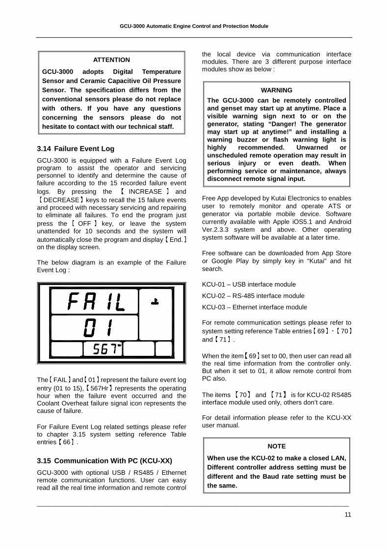
The below diagram is an example of the Failure Event Log :
The【
FAIL】and【
01】represent the failure event log entry (01 to 15),
【567Hr】represents the operating
hour when the failure event occurred and the Coolant Overheat failure signal icon represents the cause of failure.
For Failure Event Log related settings please refer to chapter 3.15 system setting reference Table entries
【66】.
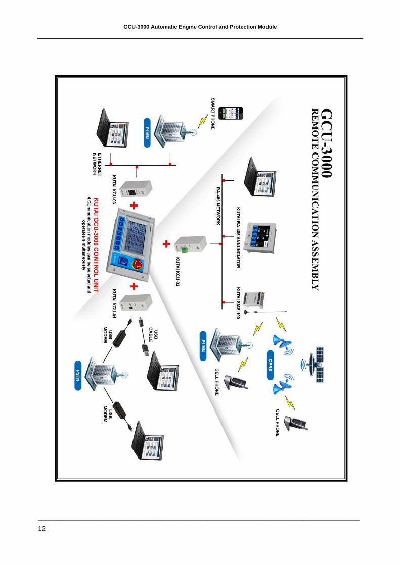
3.15 Communication With PC (KCU-XX)
GCU-3000 with optional USB / RS485 / Ethernet remote communication functions. User can easy read all the real time information and remote control
the local device via communication interface modules. There are 3 different purpose interface modules show as below :
WARNING
The GCU-3000 can be remotely controlled and genset may start up at anytime. Place a visible warning sign next to or on the generator, stating “Danger! The generator may start up at anytime!” and installing a warning buzzer or flash warning light is highly recommended. Unwarned or unscheduled remote operation may result in serious injury or even death. When performing service or maintenance, always disconnect remote signal input.
Free App developed by Kutai Electronics to enables user to remotely monitor and operate ATS or generator via portable mobile device. Software currently available with Apple iOS5.1 and Android Ver.2.3.3 system and above. Other operating system software will be available at a later time.
Free software can be downloaded from App Store or Google Play by simply key in “Kutai” and hit search.
KCU-01 – USB interface module
KCU-02 – RS-485 interface module
KCU-03 – Ethernet interface module
For remote communication settings please refer to system setting reference Table entries
【69】、【70】
and【
71】.
When the item【
69】set to 00, then user can read all the real time information from the controller only. But when it set to 01, it allow remote control from PC also.
The items 【
70】 and 【
71】 is for KCU-02 RS485 interface module used only, others don’t care.
For detail information please refer to the KCU-XX user manual.
NOTE
When use the KCU-02 to make a closed LAN, Different controller address setting must be different and the Baud rate setting must be the same.
GCU-3000 Automatic Engine Control and Protection Module
______________________________________________________________________________________
12
GCU-3000 Automatic Engine Control and Protection Module
______________________________________________________________________________________
13
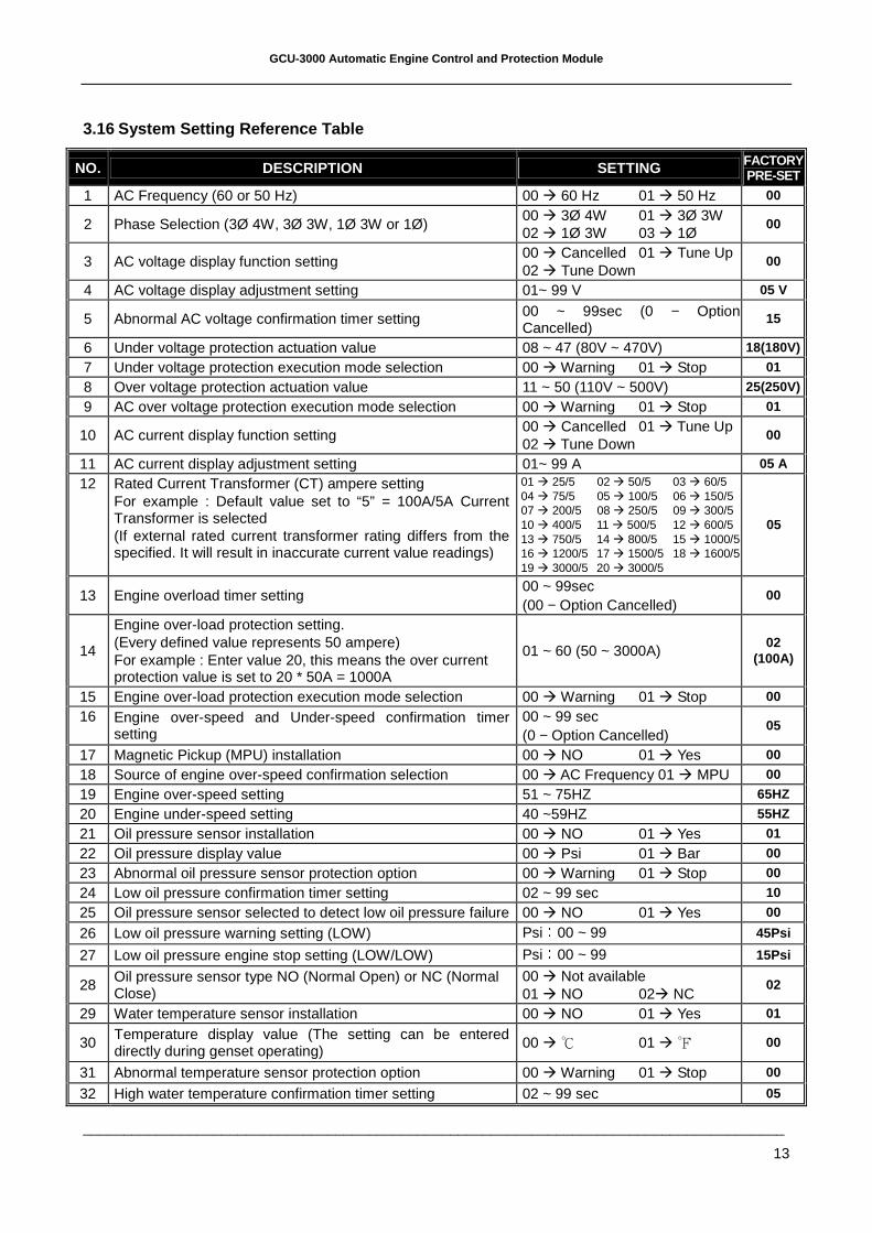
3.16 System Setting Reference Table
NO. DESCRIPTION SETTING FACTORY PRE-SET
1 AC Frequency (60 or 50 Hz) 00 60 Hz 01 50 Hz 00
2 Phase Selection (3Ø 4W, 3Ø 3W, 1Ø 3W or 1Ø) 00 3Ø 4W 01 3Ø 3W 02 1Ø 3W 03 1Ø
00
3 AC voltage display function setting 00 Cancelled 01 Tune Up 02 Tune Down
00
4 AC voltage display adjustment setting 01~ 99 V 05 V
5 Abnormal AC voltage confirmation timer setting 00 ~ 99sec (0 − Option Cancelled)
15
6 Under voltage protection actuation value 08 ~ 47 (80V ~ 470V) 18(180V)
7 Under voltage protection execution mode selection 00 Warning 01 Stop 01
8 Over voltage protection actuation value 11 ~ 50 (110V ~ 500V) 25(250V)
9 AC over voltage protection execution mode selection 00 Warning 01 Stop 01
10 AC current display function setting 00 Cancelled 01 Tune Up 02 Tune Down
00
11 AC current display adjustment setting 01~ 99 A 05 A
12 Rated Current Transformer (CT) ampere setting For example : Default value set to “5” = 100A/5A Current Transformer is selected (If external rated current transformer rating differs from the specified. It will result in inaccurate current value readings)
01 25/5 02 50/5 03 60/5 04 75/5 05 100/5 06 150/5 07 200/5 08 250/5 09 300/5 10 400/5 11 500/5 12 600/5 13 750/5 14 800/5 15 1000/5 16 1200/5 17 1500/5 18 1600/5 19 3000/5 20 3000/5
05
13 Engine overload timer setting 00 ~ 99sec (00 − Option Cancelled)
00
14
Engine over-load protection setting. (Every defined value represents 50 ampere) For example : Enter value 20, this means the over current protection value is set to 20 * 50A = 1000A
01 ~ 60 (50 ~ 3000A) 02
(100A)
15 Engine over-load protection execution mode selection 00 Warning 01 Stop 00
16 Engine over-speed and Under-speed confirmation timer setting
00 ~ 99 sec (0 − Option Cancelled)
05
17 Magnetic Pickup (MPU) installation 00 NO 01 Yes 00
18 Source of engine over-speed confirmation selection 00 AC Frequency 01 MPU 00
19 Engine over-speed setting 51 ~ 75HZ 65HZ
20 Engine under-speed setting 40 ~59HZ 55HZ
21 Oil pressure sensor installation 00 NO 01 Yes 01
22 Oil pressure display value 00 Psi 01 Bar 00
23 Abnormal oil pressure sensor protection option 00 Warning 01 Stop 00
24 Low oil pressure confirmation timer setting 02 ~ 99 sec 10
25 Oil pressure sensor selected to detect low oil pressure failure 00 NO 01 Yes 00
26 Low oil pressure warning setting (LOW) Psi:
00 ~ 99 45Psi
27 Low oil pressure engine stop setting (LOW/LOW) Psi:
00 ~ 99 15Psi
28 Oil pressure sensor type NO (Normal Open) or NC (Normal Close)
00 Not available 01 NO 02 NC
02
29 Water temperature sensor installation 00 NO 01 Yes 01
30 Temperature display value (The setting can be entered directly during genset operating)
00 01 00
31 Abnormal temperature sensor protection option 00 Warning 01 Stop 00
32 High water temperature confirmation timer setting 02 ~ 99 sec 05
GCU-3000 Automatic Engine Control and Protection Module
______________________________________________________________________________________
14
NO. DESCRIPTION SETTING FACTORY PRE-SET
33 Water temperature sensor selected to detect high water temperature failure
00 NO 01 Yes 00
34 High water temperature warning setting (HIGH) (Every defined value represents 5)
:
10 ~ 20 16(80 )
35 High water temperature engine stop setting (HIGH / HIGH) (Every defined value represents 5)
:
10 ~ 24 19(95 )
36 Is water temperature sensor selected to control space heater 00 NO 01 Yes 00
37 Space heater switch off temperature setting 00 ~ 50 25
38 Water temperature sensor type NO (Normal Open) or NC (Normal Close)
00 Not available 01 NO 02 NC
01
39 Battery under voltage protection setting 08 ~ 23 VDC 08 VDC
40 Battery over voltage protection setting 13 ~ 35 VDC 32 VDC
41 Engine pre-heat timer setting (Countdown) 00 ~ 99 sec 06
42 Allowed engine start attempt 01 ~ 09 Attempts 03
43 Starter motor cranking crank timer setting 02 ~ 30 sec 06
44 Magnetic Pickup (MPU) selected for confirming engine start 00 No 01 Yes 00
45 Oil pressure sensor selected for confirming engine start (25Psi)
00 No 01 Yes 00
46 Oil pressure switch selected for confirming engine start 00 No 01 Yes 01
47 Engine stop timer setting 02 ~ 99 sec 10
48 Engine stop (Energize to stop or energize to start) 00 Energize to stop 01 Energize to start
00
49 Engine cool-down timer setting 00 ~ 60 min 00
50 Engine idle speed timer setting 00 ~ 60 min 00
51 Engine warm up timer delay 00 ~ 99 sec 10
52 Failure warning buzzer activation 00 NO 01 Yes 01
53 Fuel level switch type NO (Normal Open) or NC (Normal Close)
00 Not available 01 NO 02 NC
00
54 Low fuel level confirmation timer 02 ~ 99 sec 10
55 Low fuel level warning execution 00 Warning 01 Stop 00
56 Customer defined Alarm1 as NO (Normal Open) or NC (Normal Close) type
00 No Alarm1 input signal 01 NO 02 NC
00
57 Customer defined Alarm1 confirmation timer 02 ~ 99 sec 10
58 Customer defined Alarm1 warning execution 00 Warning 01 Stop 00
59 Customer defined Alarm2 as NO (Normal Open) or NC (Normal Close) type
00 No Alarm2 input signal 01 NO 02 NC
00
60 Customer defined Alarm2 confirmation timer 02 ~ 99 sec 10
61 Customer defined Alarm2 warning execution 00 Warning 01 Stop 00
62 Engine service and maintenance timer setting (Every defined value represents 10 hrs) 00 ~ 99 (00 − Option cancelled) 00
63 AC voltage and Current display mode setting 00 Fixed Display 01 Cycling Display
01
64 Display line voltage (L1-N, L2-N, L3-N) if system is 3Ø (phase) 4W (wire)
00 NO 01 Yes 01
65 Display reading selection Hr, V or Hz 00 Hr 01 V 02 Hz 03 Cycling Display
02
66 Failure event log 00 NO 01 Yes 00
67 Manual start and stop operation mode 00 Normal 01 Manual 00
GCU-3000 Automatic Engine Control and Protection Module
______________________________________________________________________________________
15
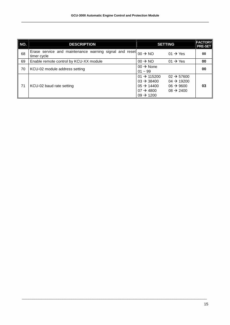
NO. DESCRIPTION SETTING FACTORY PRE-SET
68 Erase service and maintenance warning signal and reset timer cycle
00 NO 01 Yes 00
69 Enable remote control by KCU-XX module 00 NO 01 Yes 00
70 KCU-02 module address setting 00 None 01 ~ 99
00
71 KCU-02 baud rate setting
01 115200 02 57600 03 38400 04 19200 05 14400 06 9600 07 4800 08 2400 09 1200
03
GCU-3000 Automatic Engine Control and Protection Module
______________________________________________________________________________________
16
4. FAILURE WARNING DESCRIPTION
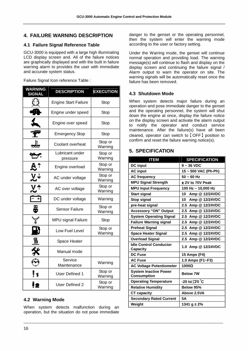
4.1 Failure Signal Reference Table
GCU-3000 is equipped with a large high illuminating LCD display screen and. All of the failure notices are graphically displayed and with the built in failure warning alarm to provides the user with immediate and accurate system status.
Failure Signal Icon reference Table :
WARNING SIGNAL DESCRIPTION EXECUTION
Engine Start Failure Stop
Engine under speed Stop
Engine over speed Stop
Emergency Stop Stop
Coolant overheat
Stop or Warning
Lubricant under
pressure Stop or Warning
Engine overload
Stop or Warning
AC under voltage
Stop or Warning
AC over voltage
Stop or Warning
DC under voltage Warning
Sensor Failure
Stop or Warning
MPU signal Failure Stop
Low Fuel Level
Stop or Warning
Space Heater
Manual mode
Service
Maintenance Warning
User Defined 1 Stop or Warning
User Defined 2 Stop or Warning
4.2 Warning Mode
When system detects malfunction during an operation, but the situation do not pose immediate
danger to the genset or the operating personnel, then the system will enter the warning mode according to the user or factory setting.
Under the Warring mode, the genset will continue normal operation and providing load. The warning message(s) will continue to flash and display on the display screen and continuing the failure signal / Alarm output to warn the operator on site. The warning signals will be automatically reset once the failure has been removed.
4.3 Shutdown Mode
When system detects major failure during an operation and pose immediate danger to the genset and the operating personnel, the system will shut down the engine at once, display the failure notice on the display screen and activate the alarm output to notify the operator and conduct service maintenance. After the failure(s) have all been cleared, operator can switch to
【OFF】position to
confirm and reset the failure warning notice(s).
5. SPECIFICATION
ITEM SPECIFICATION DC input 9 ~ 36 VDC
AC input 15 ~ 500 VAC (Ph-Ph)
AC frequency 50 ~ 60 Hz
MPU Signal Strength ±±±± 2V to 70V Peak
MPU Input Frequency 100 Hz ~ 10,000 Hz
Start signal 10 Amp @ 12/24VDC
Stop signal 10 Amp @ 12/24VDC
pre-heat signal 2.5 Amp @ 12/24VDC
Accessory “ON” Output 2.5 Amp @ 12/24VDC
System Operating Signal 2.5 Amp @ 12/24VDC
Failure Warning signal 2.5 Amp @ 12/24VDC
Preheat Signal 2.5 Amp @ 12/24VDC
Space Heater Signal 2.5 Amp @ 12/24VDC
Overload Signal 2.5 Amp @ 12/24VDC
Idle Control Conductor Capacity 1.0 Amp @ 12/24VDC
DC Fuse 15 Amps (F4)
AC Fuse 1.0 Amps (F1~F3)
AC Voltage Potentiometer 1000Ω
System Inactive Power Consumption Below 7W
Operating Temperature -20 to ++++70 °°°°C
Relative Humidity Below 95%
CT capacity Above 2.5VA
Secondary Rated Current 5A
Weight 1341 g ± 2%
GCU-3000 Automatic Engine Control and Protection Module
______________________________________________________________________________________
17
6. TERMINAL & WIRING DESCRIPTION
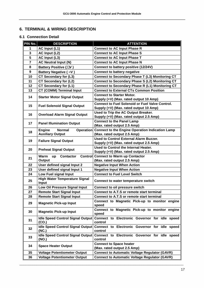
6.1 Connection Detail
PIN No. DESCRIPTION ATTENTION 1 AC Input (L1) Connect to AC Input Phase R 3 AC Input (L2) Connect to AC Input Phase S 5 AC Input (L3) Connect to AC Input Phase T 7 AC Neutral Input (N) Connect to AC Input Phase N 8 Battery Positive ( ++++V ) Connect to battery positive (12/24V) 9 Battery Negative ( −−−−V ) Connect to battery negative 10 CT Secondary for (L3) Connect to Secondary Phase T (L3) Monitoring CT 11 CT Secondary for (L2) Connect to Secondary Phase S (L2) Monitoring CT 12 CT Secondary for (L1) Connect to Secondary Phase R (L1) Monitoring CT 13 CT (COMM) Terminal Input Connect to External CTs Common Position
14 Starter Motor Signal Output Connect to Starter Motor. Supply (+V) (Max. rated output 10 Amp)
15 Fuel Solenoid Signal Output Connect to Fuel Solenoid or Fuel Valve Control. Supply (+V) (Max. rated output 10 Amp)
16 Overload Alarm Signal Output Used to Trip the AC Output Breaker. Supply (+V) (Max. rated output 2.5 Amp)
17 Panel Illumination Output Connect to the Panel Lamp (Max. rated output 2.5 Amp)
18 Engine Normal Operation Auxiliary Output
Connect to the Engine Operation Indication Lamp (Max. rated output 2.5 Amp)
19 Failure Signal Output Used to Control External Alarm Buzzer. Supply (+V) (Max. rated output 2.5 Amp)
20 Preheat Signal Output Used to Control the Internal Heater. Supply (+V) (Max. rated output 2.5 Amp)
21 Warm up Contactor Control Output
Connect to Warm up Contactor (Max. rated output 2.5 Amp)
22 User defined signal Input 2 Negative Input When Action 23 User defined signal Input 1 Negative Input When Action 24 Low Fuel signal Input Connect to Fuel Level Swit ch
25 High Water Temperature Signal Input Connect to water temperature switch
26 Low Oil Pressure Signal Input Connect to oil pre ssure switch 27 Remote Start Signal Input Connect to A.T.S or re mote start terminal 28 Remote Start Signal Input Connect to A.T.S or re mote start terminal
29 Magnetic Pick-up Input Connect to Magnetic Pick-up to monitor engine speed
30 Magnetic Pick-up Input Connect to Magnetic Pick-up to monitor engine speed
31 Idle Speed Control Signal Output (CO.)
Connect to Electronic Governor for idle speed control
32 Idle Speed Control Signal Output (NC.)
Connect to Electronic Governor for idle speed control
33 Idle Speed Control Signal Output (NO.)
Connect to Electronic Governor for idle speed control
34 Space Heater Output Connect to Space heater (Max. rated output 2.5 Amp)
35 Voltage Potentiometer Output Connect to Automati c Voltage Regulator (GAVR) 36 Voltage Potentiometer Output Connect to Automati c Voltage Regulator (GAVR)
GCU-3000 Automatic Engine Control and Protection Module
______________________________________________________________________________________
18
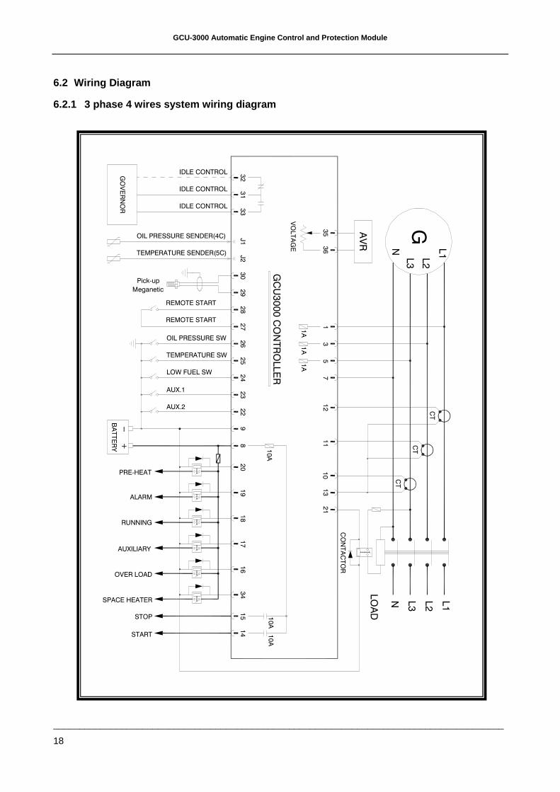
6.2 Wiring Diagram
6.2.1 3 phase 4 wires system wiring diagram
AUXILIARY
SPACE HEATER
STOP
START
OVER LOAD
RUNNING
PRE-HEAT
ALARM
AUX.2
AUX.1
LOW FUEL SW
BATTERY
+GOVERNOR
OIL PRESSURE SW
REMOTE START
REMOTE START
TEMPERATURE SW
Pick-up
Meganetic
OIL PRESSURE SENDER(4C)
TEMPERATURE SENDER(5C)
IDLE CONTROL
IDLE CONTROL
IDLE CONTROL
1A
GCU3000 CONTROLLER
CONTACTOR
10A
34
15
14
10A
16
L3
LOAD
N L1
L2
10A
17
18
19
20
21
10
13
22
89
23
24
11
712
30
26
25
27
28
29
13
5
1A
1A
VOLTAGE
J2
J1
33
31
35
36
GL3
AVR N L1L2
32
CT
CT
CT
GCU-3000 Automatic Engine Control and Protection Module
______________________________________________________________________________________
19
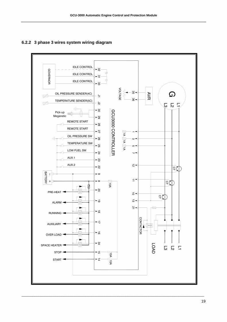
6.2.2 3 phase 3 wires system wiring diagram
VOLTAGE
L1
LOW FUEL SW
OIL PRESSURE SENDER(4C)
TEMPERATURE SENDER(5C)
IDLE CONTROL
IDLE CONTROL
IDLE CONTROL
Meganetic
Pick-up
REMOTE START
TEMPERATURE SW
REMOTE START
OIL PRESSURE SW
33
32
31
J1
J2
G
27
29
30
28
31
5
26
25
24 7
12
ALARM
RUNNING
PRE-HEAT
+
BATTERY
AUX.2
AUX.1
START
STOP
SPACE HEATER
AUXILIARY
OVER LOAD
13
23
22
98
11
10
19
20
10A
18
21
15
17
16
34
10A
10A
14
LOAD
L3
L2
L1
36
35 AVR
1A
1A
1A
GCU3000 CONTROLLER
L3
L2
GOVERNOR
CONTACTOR
CT
CT
CT

GCU-3000 Automatic Engine Control and Protection Module
______________________________________________________________________________________
20
6.2.3 1 phase 3 wires system wiring diagram
AUXILIARY
SPACE HEATER
STOP
START
OVER LOAD
RUNNING
PRE-HEAT
ALARM
AUX.2
AUX.1
LOW FUEL SW
BATTERY
+
OIL PRESSURE SW
REMOTE START
REMOTE START
TEMPERATURE SW
Pick-up
Meganetic
OIL PRESSURE SENDER(4C)
TEMPERATURE SENDER(5C)
IDLE CONTROL
IDLE CONTROL
IDLE CONTROL
1A
GCU3000 CONTROLLER
10A
34
15
14
10A
16
LOAD
L2
N L1
10A
17
18
19
20
21
10
13
22
89
23
24
11
712
30
26
25
27
28
29
13
5
1A
1A
VOLTAGE
J2
J1
33
31
35
36
GAVR
L2
N L1
32GOVERNOR
CONTACTOR
CT
CT
GCU-3000 Automatic Engine Control and Protection Module
______________________________________________________________________________________
21
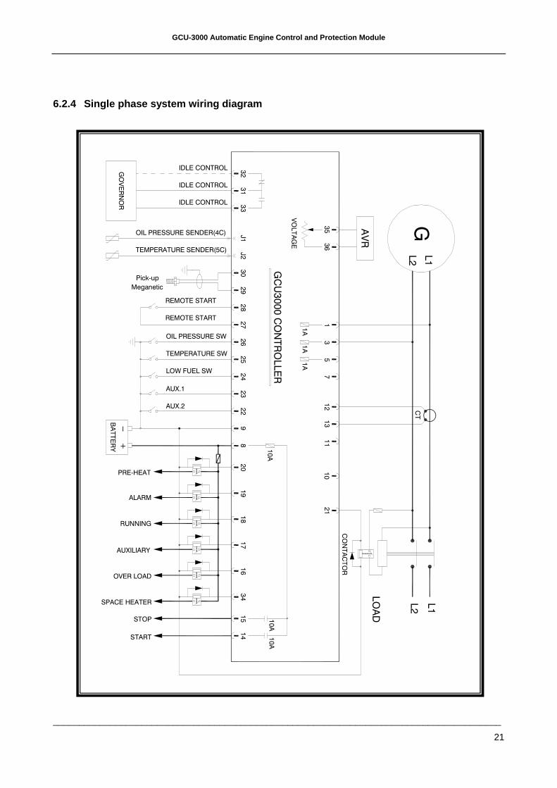
6.2.4 Single phase system wiring diagram
SPACE HEATER
START
STOP
OVER LOAD
AUXILIARY
ALARM
RUNNING
AUX.2
+
BATTERY
PRE-HEAT
TEMPERATURE SW
REMOTE START
OIL PRESSURE SW
LOW FUEL SW
AUX.1
TEMPERATURE SENDER(5C)
OIL PRESSURE SENDER(4C)
REMOTE START
Meganetic
Pick-up
IDLE CONTROL
IDLE CONTROL
IDLE CONTROL
19
10A
14 10A
15
34
16
17
18
21
LOAD
L1
L2
28
GCU3000 CONTROLLER
820
10A
922
11
10
12
24
23
25
27
26 1A
57
1A
31
1A
VOLTAGE
J2
29
30
J1
36
35
31
33
32
L2
GAVR
L1
13
CT
GOVERNOR
CONTACTOR
GCU-3000 Automatic Engine Control and Protection Module
______________________________________________________________________________________
22
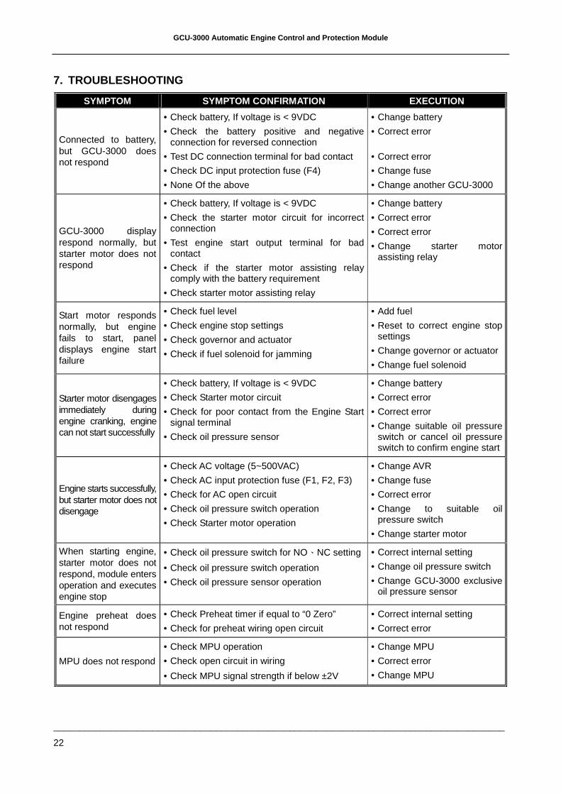
7. TROUBLESHOOTING
SYMPTOM SYMPTOM CONFIRMATION EXECUTION
Connected to battery, but GCU-3000 does not respond
• Check battery, If voltage is < 9VDC
• Check the battery positive and negative connection for reversed connection
• Test DC connection terminal for bad contact
• Check DC input protection fuse (F4)
• None Of the above
• Change battery
• Correct error
• Correct error
• Change fuse
• Change another GCU-3000
GCU-3000 display respond normally, but starter motor does not respond
• Check battery, If voltage is < 9VDC
• Check the starter motor circuit for incorrect connection
• Test engine start output terminal for bad contact
• Check if the starter motor assisting relay comply with the battery requirement
• Check starter motor assisting relay
• Change battery
• Correct error
• Correct error
• Change starter motor assisting relay
Start motor responds normally, but engine fails to start, panel displays engine start failure
• Check fuel level
• Check engine stop settings
• Check governor and actuator
• Check if fuel solenoid for jamming
• Add fuel
• Reset to correct engine stop settings
• Change governor or actuator
• Change fuel solenoid
Starter motor disengages immediately during engine cranking, engine can not start successfully
• Check battery, If voltage is < 9VDC
• Check Starter motor circuit
• Check for poor contact from the Engine Start signal terminal
• Check oil pressure sensor
• Change battery
• Correct error
• Correct error
• Change suitable oil pressure switch or cancel oil pressure switch to confirm engine start
Engine starts successfully, but starter motor does not disengage
• Check AC voltage (5~500VAC)
• Check AC input protection fuse (F1, F2, F3)
• Check for AC open circuit
• Check oil pressure switch operation
• Check Starter motor operation
• Change AVR
• Change fuse
• Correct error
• Change to suitable oil pressure switch
• Change starter motor
When starting engine, starter motor does not respond, module enters operation and executes engine stop
• Check oil pressure switch for NO、NC setting
• Check oil pressure switch operation
• Check oil pressure sensor operation
• Correct internal setting
• Change oil pressure switch
• Change GCU-3000 exclusive oil pressure sensor
Engine preheat does not respond
• Check Preheat timer if equal to “0 Zero”
• Check for preheat wiring open circuit
• Correct internal setting
• Correct error
MPU does not respond
• Check MPU operation
• Check open circuit in wiring
• Check MPU signal strength if below ±2V
• Change MPU
• Correct error
• Change MPU
GCU-3000 Automatic Engine Control and Protection Module
______________________________________________________________________________________
23
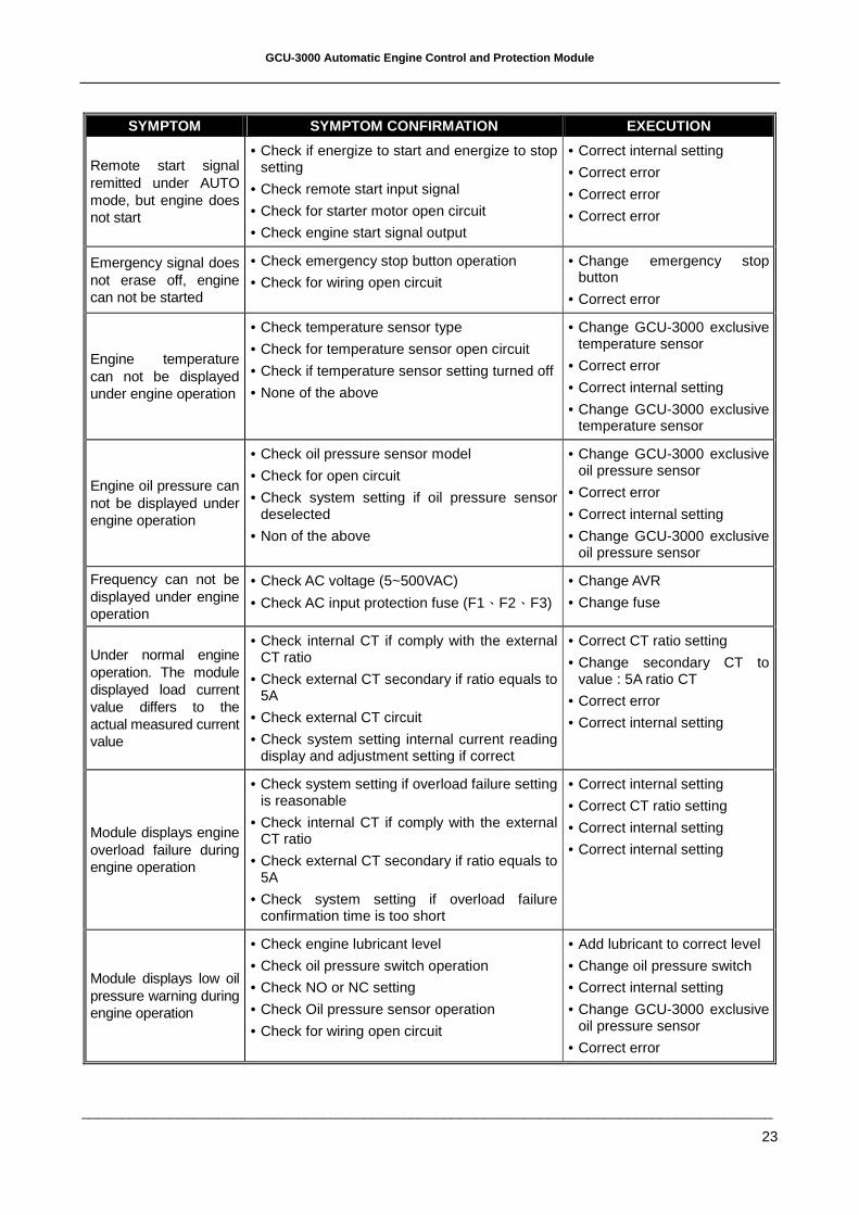
SYMPTOM SYMPTOM CONFIRMATION EXECUTION
Remote start signal remitted under AUTO mode, but engine does not start
• Check if energize to start and energize to stop setting
• Check remote start input signal
• Check for starter motor open circuit
• Check engine start signal output
• Correct internal setting
• Correct error
• Correct error
• Correct error
Emergency signal does not erase off, engine can not be started
• Check emergency stop button operation
• Check for wiring open circuit
• Change emergency stop button
• Correct error
Engine temperature can not be displayed under engine operation
• Check temperature sensor type
• Check for temperature sensor open circuit
• Check if temperature sensor setting turned off
• None of the above
• Change GCU-3000 exclusive temperature sensor
• Correct error
• Correct internal setting
• Change GCU-3000 exclusive temperature sensor
Engine oil pressure can not be displayed under engine operation
• Check oil pressure sensor model
• Check for open circuit
• Check system setting if oil pressure sensor deselected
• Non of the above
• Change GCU-3000 exclusive oil pressure sensor
• Correct error
• Correct internal setting
• Change GCU-3000 exclusive oil pressure sensor
Frequency can not be displayed under engine operation
• Check AC voltage (5~500VAC)
• Check AC input protection fuse (F1、F2、F3)
• Change AVR
• Change fuse
Under normal engine operation. The module displayed load current value differs to the actual measured current value
• Check internal CT if comply with the external CT ratio
• Check external CT secondary if ratio equals to 5A
• Check external CT circuit
• Check system setting internal current reading display and adjustment setting if correct
• Correct CT ratio setting
• Change secondary CT to value : 5A ratio CT
• Correct error
• Correct internal setting
Module displays engine overload failure during engine operation
• Check system setting if overload failure setting is reasonable
• Check internal CT if comply with the external CT ratio
• Check external CT secondary if ratio equals to 5A
• Check system setting if overload failure confirmation time is too short
• Correct internal setting
• Correct CT ratio setting
• Correct internal setting
• Correct internal setting
Module displays low oil pressure warning during engine operation
• Check engine lubricant level
• Check oil pressure switch operation
• Check NO or NC setting
• Check Oil pressure sensor operation
• Check for wiring open circuit
• Add lubricant to correct level
• Change oil pressure switch
• Correct internal setting
• Change GCU-3000 exclusive oil pressure sensor
• Correct error
GCU-3000 Automatic Engine Control and Protection Module
______________________________________________________________________________________
24
SYMPTOM SYMPTOM CONFIRMATION EXECUTION
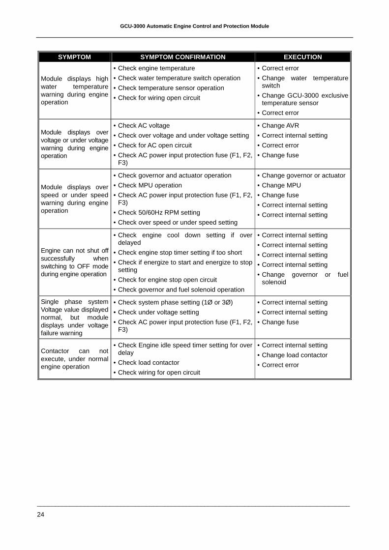
Module displays high water temperature warning during engine operation
• Check engine temperature
• Check water temperature switch operation
• Check temperature sensor operation
• Check for wiring open circuit
• Correct error
• Change water temperature switch
• Change GCU-3000 exclusive temperature sensor
• Correct error
Module displays over voltage or under voltage warning during engine operation
• Check AC voltage
• Check over voltage and under voltage setting
• Check for AC open circuit
• Check AC power input protection fuse (F1, F2, F3)
• Change AVR
• Correct internal setting
• Correct error
• Change fuse
Module displays over speed or under speed warning during engine operation
• Check governor and actuator operation
• Check MPU operation
• Check AC power input protection fuse (F1, F2, F3)
• Check 50/60Hz RPM setting
• Check over speed or under speed setting
• Change governor or actuator
• Change MPU
• Change fuse
• Correct internal setting
• Correct internal setting
Engine can not shut off successfully when switching to OFF mode during engine operation
• Check engine cool down setting if over delayed
• Check engine stop timer setting if too short
• Check if energize to start and energize to stop setting
• Check for engine stop open circuit
• Check governor and fuel solenoid operation
• Correct internal setting
• Correct internal setting
• Correct internal setting
• Correct internal setting
• Change governor or fuel solenoid
Single phase system Voltage value displayed normal, but module displays under voltage failure warning
• Check system phase setting (1Ø or 3Ø)
• Check under voltage setting
• Check AC power input protection fuse (F1, F2, F3)
• Correct internal setting
• Correct internal setting
• Change fuse
Contactor can not execute, under normal engine operation
• Check Engine idle speed timer setting for over delay
• Check load contactor
• Check wiring for open circuit
• Correct internal setting
• Change load contactor
• Correct error