Embed Size (px)
Citation preview

1 PROCAVORK PLAN NO. I PROCEDUREIWORK P U N TILE: I PAGE: 6 of 52 I
8.0 INSTRUCTIONS
2403.002
8.1 PERFORMANCE DISCHARGE TEST SET UP.
8.1.1 Removal of 2D12 from service:
UNIT 11 2D12 PERFORMANCE TEST ELECTRICAL MAINTENANCE
A. Verify Charger 2D32 is powered up and supplying power for Bus 2D02.
R N : 005 CHANGE: 02-1
B. Obtain assistance from Operations to aid g d //I?-99 with the removal of 2D12 from service.
C. Open the battery disconnect switch, 2D52 $hl / / . /999
WARNING The 2D02 side of the fuse connections are energized. Avoid contact when 11 removing the fuses. II
8.1.2 Remove the 1800 amp fuses.
WARNING The Battery side of the fuse connections are energized. Avoid contact when removing the fuses.
IL 11
8.1.3 Remove the pin indicating fuses from 2D42.
8.1.4 Verify that Handswitch AS1 on 2D42 is in the ,PA /L&99 "NORMAL" position.
WARNING The 2D02 side of the fuse connections are energized. Avoid contact when bolting cables from test load device.
8.1.5 Bolt the cables from the test load device to the battery side of the 1800 amp fuse connector.

1 PRDCIWORK PLAN NO. ( PROCFiDURWORK P U N TmE: PAGE: 7of52 1 I UNIT 11 2D12 PERFORMANCE TEST REV:
ELECTRICAL MAINTENANCE CHANOE: 02-1
NOTE This section is to determine the condition of battery connections before the performance discharge test. No repair is to be effected if a high resistance reading is noted. This connection or connections must be watched during the discharge test for excessive heating.
QC HOLD A QC inspector must be present to witness the reading of the battery connection resistances and sign Data Sheet 1 upon coE?pletion.
NOTE 1
A Second person shall verify micro-ohmreadings as they are being recorded on Data Sheet 1 and sign Data Sheet 1 upon completion.
8.1.6 Measure the cell-to-cell and terminal connection resistance to the nearest micro-ohm as directed below:
NOTE The DLRO's batterv test meter will indicate the relative state of charge of 1 the DLRO battery.- I
A. Check the DLRO display and measuring , circuit batteries.
B. IF the DLRO's batteries are low, THEN connect the charser to the unit =he batteries are OK, THEN mark this step N/A.
C. Separate the two sets of test leads and connect the DLRO as follows:
#, , 1. Connect the black lead wire of the '&&(I /-15-'?9
first set, (marked 'C") to the terminal marked 'Cl".
2. Connect the red lead wire of the first /-1$'-9 set, (marked 'Pn) to the terminal marked "PI'
3. Connect the black lead wire of the &d/,-!g-9 second set, (marked "C") to the terminal marked "CZ'.
4 . Connect the red lead wire of the second set, (Marked "P') to the terminal marked 'P2".

NOTE The user should select the lowest range possible on the DLRO that is greater than 150 micro-ohms, this will ensure that they are measuring micro-ohms to the right of the decimal point.
PROCJWORK PLAN NO.
2403.002
D. Set the DLRO to the lowest possible resistance range, that is greater than 150 micro-ohms.
E. Turn the ONIOFF switch to the 'ON' (lock) &/ 1- I%-* position
PROCEDURVWORK PLAN TITLE:
UNIT 11 2D12 PERFORMANCE TEST ELECTRICAL MAINTENANCE
NOTE - Each of the two test probes has the letter "P' on one face. This side of each probe should be in the same orientation to one another e , if the "Pn on one probe is facing inside, the 'P" on the other probe should also face inside.)
4
PAGE: 8 of 52 REV: 005 CHANGE: 02-1
I -
The probes should not be placed across a voltage source! The test probes should not be connected to a positive and negative posts of the same cell. I
- - the bus cable connection. Connections may be measured in any sequence so long as each connection on Data Sheet 3 is tested.
a
NOTE The micro-ohm test for the intercell strap and cable connections should be measured from: battery post to battery post, battery post to terminal plate, and terminal plate to all cable terminal lugs.
NOTE In the step below, the statement 'connect the test probes to the left most ..: is an attempt to explain the measuring technique to you the user. It is not an instruction or limitation implying that you must begin at the left-most cell or that you cannot begin with cell number 1, besinnina with
F. Repeat the following steps 1 through 4 for all battery terminal to battery terminal. battery terminal to terminal plate and terminal plate to terminal lugs and record the "As Found' micro-ohm readings on data sheet 1.
ACCEPTANCE - IF any recorded 'As Found" reading in the following steps CRITERION exceeds the Technical Specification allowable value of
150 micro-ohms: THEN initiate a Condition Report and have the Cognizant Supervisor and/or the Maintenance Engineer perform an evaluation to determine if it is safe to proceed with the Service Discharge Test.

PROCJWORK PLAN NO. PROCEDURWORK P U N TITLE: PAGE: 9 d s 2 I 1 2403.002 I u ~ r r 11 2 ~ 1 2 PERFORMANCE TEST ELECTRICAL MAINTENANCE I
IF any single 'As Found" .reading obtained in the - following steps is questionable (too high exceeding 150 micro-ohms), THEN move the "Forward/Reverse" lever to "Reverse" and average the two readings, IF average of the two readings is acceptable, - THEN proceed with remainder of test. - IF average of two readings is still questionable, - THEN initiate a Condition Report and have the Cognizant Supervisor and/or Maintenance Engineer perform an evaluation to determine if it is safe to proceed with the Service Discharge Test,
For battery terminal to battery terminal connections:
a. Connect the probes to the left-most positive post (PI) of one cell and the left-most negative post (N1) of the adjacent cell. Obtain reading and record on data sheet 1.
b. Connect the probes to the next left-most positive post (P2) and to the next left-most negative post (N2) of adjacent cell. Obtain reading and record on data sheet 1.
For battery terminal to terminal plate connections:
a. IF testing positive posts to terminal sate, THEN connect the probes to the left- most positive post (PI) of cell and the terminal plate. K E N connect the probes to the next positive post (P2) of same cell and the terminal plate. Obtain reading and record on data sheet 1.
b. IF testing negative posts to terminal plate, THEN connect the probes to the left- most negative post (Nl) of cell and the terminal plate. THEN connect the probes to the next nesative post (N2) of same cell and the terminal plate. Obtain reading and record on data sheet 1.
For terminal plate to wire terminal lug connections, connect the probes to the plate and each wire lug connected to the plate. Perform this step for each lug listed on data sheet, obtain readings and record on data sheet 1.

8.2 MEASURING CELL TEMPERATURE
PROCJWORK PLAN NO.
2403.002
8.2.1 Measure the cell temperature of each individual cell as listed on Attachment 1.
CAUTION use extreme caution when inserting and removina the thermometer from the 3
PROCEDUREWORK PLAN TITLE: .
UNK 11 2D12 PERFORMANCE TEST ELECTRICAL MAINTENANCE
sampling tube to avoid breaking the thermomete;. If breakage occurs and parts of the thermometer remain in the battery, the Electrical Maintenance Supervisor should be notified as soon as possible.
PAGE: 10 d 52 RN: 005 CHANGE: 02-1
NOTE IF the front sample tube is bent or broken, - THEN the thermometer may be placed in the rear sample tube.
I I
NOTE A Second Person shall observe, sign and verify after completion, that steps A through C have been completed for all cells listed on Attachment 1 and this value recorded.
NOTE Repeat steps 8.2.1.A through 8.2.1.C until all of the cells listed on Attachment 1 been measured.
I I
A. Place the thermometer in the sample tube of the individual cell being measured. Thermometer should rest on the upper sample tube housing.
B. Leaving the thermometer in .zhe cell being measured for 15 seconds will allow the reading to stabilize.
C. Record the temperature to the nearest OF for each cell on Attachment 1.
SECOND PERSON VERIFIER
An Second Person Verifier shall verify here and on Attachment 1 that A
temperature values were properly recorded
/ -@r~ 1- - econd persyfverifier Date

D. IF any of the monitored cells have bent or Eoken sample tubes, or broken thermometer parts in the cell, THEN record the cell number in the space - provided below, and notify the Electrical Maintenance Supervisor:
PROCJWORK PLAN NO.
2403.002
IF NOT, THEN mark this step N/A.
Supervisor Remarks:
PROCEDUREWORK PLAN TITLE:
UNIT 11 2012 PERFORMANCE TEST ELECTRICAL MAINTENANCE
E. IF any cell temperature deviates more than 3°C (5OF) from the other cells during inspection, THEN notify the Electrical Maintenance - Supervisor:
PAGE: 11 of52 REV: 005 CHANGE: 02-1
-
IF NOT, THEN mark this step N/A.
Supervisor Remarks:
F. Calculate and record on Attachment 1 the average cell temperature of the monitored cells listed on Attachment 1.
8.3 BATTERY PERFORMRNCE DISCHARGE TEST
8.3.1 Connect any remaining battery load test set control wiring needed for load monitoring or control.
8.3.2 Determine and record on Attachment 1 and below the discharge current correction factor (K Factor) based upon the average cell temperature obtained in Step 8.2.1 and the Table on Attachment 1.
(K Factor) Discharge Current Correction Factor: I- 000

SECOND PERSON VERIFIER
PROCJWORK P U N NO.
2403.002
A Second Person Verifier shall determine and record below the discharge current correction factor (K Factor) based upon the average cell temperature obtained in Step 8.2.1 and the Table on Attachment 1.
(K Factor) Discharge Factor: 1- @QU
!
PROCEOURWORK P U N T m E :
UNIT 11 2012 PERFORMANCE TEST ELECTRICAL MAINTENANCE
8.3.3 Calculate the actual di!k&kge current by dividing 258 by the K Factor from Step 8.3.2.
PAGE: 12Of52 REV: 005 CHANGE: 02-1
258 amps - /-8ou = , 25-57 Rated discharge K Factor Actual discharge current current
258 Amps = 2q5 ~ m p s (K)
SECOND PERSON VERIFIER
A Second Person Verifier is to calculate the actual discharge current by dividing 258 by the K Factor from Step 8.3.2 and record below.
258 amps + /.Q@ = 258 Rated discharge K Factor Actual discharge current current
258 Amps = 2 553 (K)
8.3.4 Set up the load tester to amps calculated in Steps 8.3.3 and 9 hours of discharge. cu / - z z9
SECOND PERSON VERIFIER
A Second Person Verifier shall verify that up correctly for a 9 hour discharge at the in Step 8.3.3.
W.@ 1- - Date
8.3.5 Cognizant Supervisor shauerify calculations are correct and has granted permission to start the test.
A L L /m- e 7 Cognizant supervisor- ate
8.3.6 Close 2D52 disconnect switch.
--
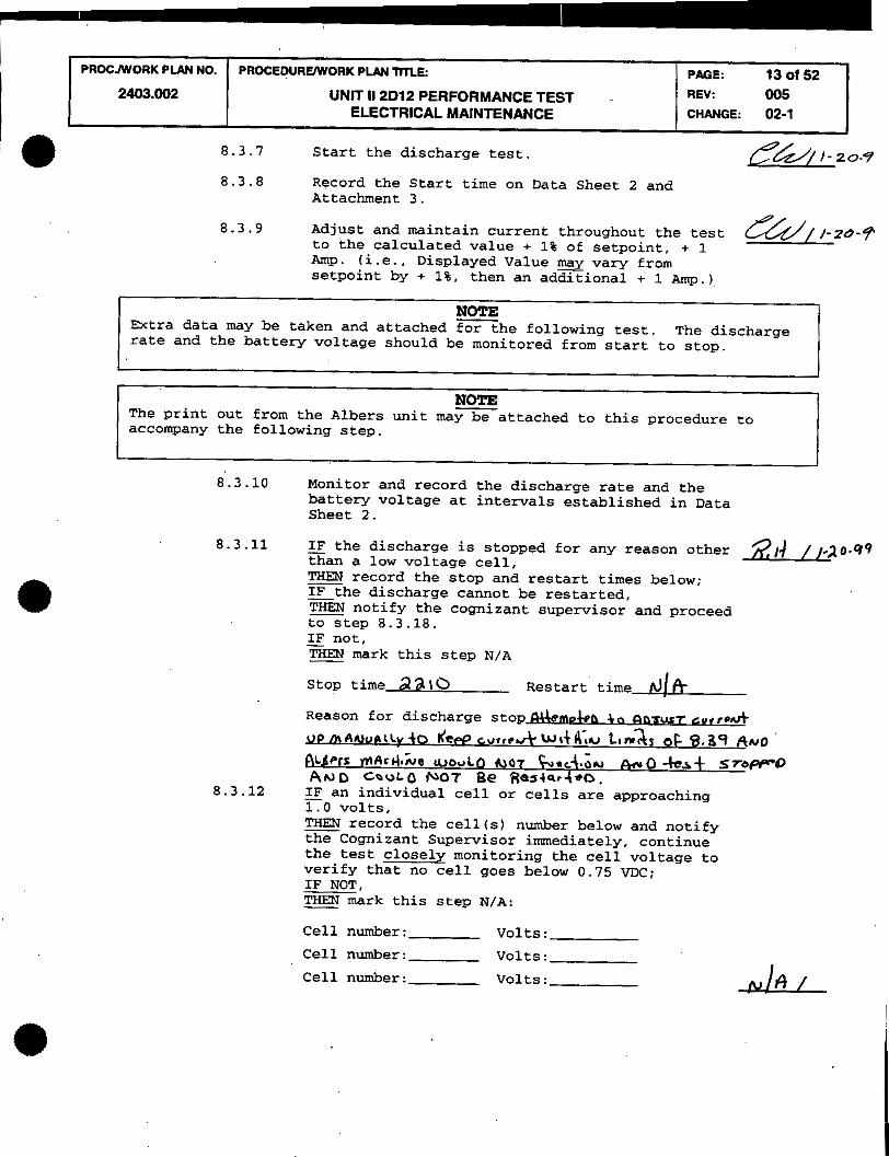
8.3.7 Start the discharge test.
8.3.8 Record the Start time on Data Sheet 2 and Attachment 3.
PROCJWORK PLAN NO.
2403.002
8.3.9 Adjust and maintain current throughout the test @/ ,-//.lo-? to the calculated value + 1% of setpoint, + 1 Amp. (i.e., Displayed Value may vary from setpoint by + 1%, then an adGional + 1 AITQ.)
NOTE - hrtra data may be taken and attached for the following test. The discharge rate and the battery voltage should be monitored from start to stop.
NOTE - The print out from the Albers unit may be attached to this procedure to accompany the following step.
8.3.10 Monitor and record the discharge rate and the battery voltage at intervals established in Data Sheet 2.
8.3.11 IF the discharge is stopped for any reason other - than a low voltage cell, 217' //*20.99 = record the stop and restart times below; IF the discharge cannot be restarted, - THEN notify the cognizant supervisor and proceed - to step 8.3.18.
PROCEDUREWORK PLAN TmE:
IF not, - THEN mark this step N/A -
UNIT 11 2D12 PERFORMANCE TEST ELECTRICAL MAINTENANCE
stop time d a \ O Restart time hl!& Reason for discharge stopAemokb 4, an=-7 cur,*&
f i m o i w v + o ~ P P c w r r u t wd~;., L,,& op $339 A,,,0
8.3.12 IF an individual cell or cells are approaching 1.0 volts.
PAGE: 13 of 52 REV: 005 CHANGE: 02-1
~ - - - , THEN record the cell(s) number below and notify - the Cognizant Supervisor immediately, continue the test closely monitoring the cell voltage to verify that no cell goes below 0.75 M C ; IF NOT, THEN mark this step N/A: - Cell number: Volts:
Cell number: Volts:
Cell number: Volts:
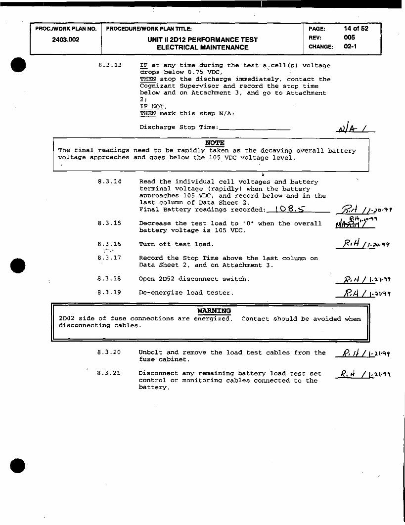
8.3.13 - IF at any time during the test a,.cell(s) voltage drops below 0.75 VDC, THEN stop the discharge immediately, contact the Cognizant Supervisor and record the stop time below and on Attachment 3. and go to Attachment 2:
PROCJWORK P M NO.
2403.002
IF NOT, THEN mark this step N/A:
Discharge Stop Time:
NOTE - The final readings need to be rapidly taken as the decaying overall battery voltage approaches and goes below the 105 VDC voltage level.
PROCEDURUWORK PLEA lHLE:
UNIT 11 2D12 PERFORMANCE TEST ELECTRICAL MAINTENANCE
b 8.3.14 ~ e a d the individual cell voltages and battery
terminal voltage (rapidly) when the battery approaches 105 VDC, and record below and in the
PAGE: 14 of 52 REV: 005 CHANGE: 02-1
last column of Data Sheet 2. Final Battery readings recorded: 1 0 8. <
8.3.15 Decrease the test load to "0' when the overall battery voltage is 105 VDC.
8.3.16 Turn off test load. . .. - 8 .
8.3.17 Record the Stop Time above the last column on Data Sheet 2, and on Attachment 3.
8.3.18 Open 2D52 disconnect switch.
8.3.19 De-energize load tester.
WARNING 2D02 side of fuse connections are energized. Contact should be avoided when 1) disconnecting cables. II
8.3.20 Unbolt and remove the load test cables from the p, 1 ) / I-~I+, fuse' cabinet.
8.3.21 Disconnect any remaining battery load test set R. 4 / 1-21-97 control or monitoring cables connected to the battery.

PROCmORK PLAN NO. PROCEDURVWORK PLPH TITLE: PAGE: 15 of 52 I I 2403.002 I UNIT 11 2D12 PERFORMANCE TEST REV:
ELECTRICAL MAINTENANCE CHANGE: 02-1
8.4 EQUALIZE CHARGE AND BATTERY RESTORATION
8.4.1 Place the battery on equalize charge by one of the following methods as directed by Cognizant Supervision. Supervision to record below the method to be used.
J Method 1 - Method 2 - Method 3 -
"Method 1" A.
B.
C.
D.
Install the pin indicating fuses in 2D42.
Install the 1800 Amp fuses.
Close the 2D52 Disconnect Switch
Verify that the electrical lineup is restored and the charger is working properly.
Record below .the charger being used.
Charger used:
Place the battery on an equalize charge. (Charger set point is 135.2 to 138 volts) Record below the equalizing start time and voltage.
1- - Start time Date Voltage
NOTE Step 8.5 may be performed at any time after Step 8.4.1.F has been accomplished.
G. Record below the equalize voltage at the battery after 15 hours from the start of equalization.
Battery Terminal Voltage: VDC
MT&E used: Cal. Due: L H. =EN the equalize charge current reaches
the range of 11-22 amps (end of charge current) , THEN place the battery on float charge. - Record below the equalizing stop time, date, and voltage.
/ - - / Stop time Date Voltage
2

~ R O C J ~ O R K PIAN N O I PROCEDURE~ORK PLAN m~: I PAGE: 16ot52 1
'Method 2"
I
. A. Install the pin indicating fuses in 2D42. . /
B. Install the 1800 Amp fuses. L
2403.002
C. Close the 2D52 Disconnect Switch. 2 D. Verify that the electrical lineup is
restored and the charger is working d
properly.
. ..
UNIT 11 2D12 PERFORMANCE TEST ELECTRICAL MAINTENANCE
E. Record below the charger being used.
REV. 005 CHANGE: 02-1
Charger used:
F. Place the battery on an equalize charge and set the equalize voltage to 140 VDC bin 139 max 140) (maximum allowable system voltage). Record below the equalizing start time and voltage.
1- Start time Date Voltage
NOTE Step 8.5 may he performed at any time after Step 8.4 .I.F has been accomplished.
G. Monitor electrolyte temperature to ensure it does not exceed 120 de9.F during the high level equalize charge.
H. Record below the equalize voltage at the battery after 15 hours fromthe start of ,equalization.
Battery Terminal Voltage: VDC
MT&E used: Cal . Due: .
I. the equalize charge current reaches the range of 11-22 amps (end of charge current) , Reset the equalize charge back to 135.2 to 138 volts, THEN place the battery on float charge Record below the equalizing stop time, date, and voltage.
/ - / - Stop time Date Voltage

PROCJWORK P M NO. PROCEDUREWORK PLAN TITLE:
a 'Method 3" A. Install the pin indicating fuses in 2D42.
NOTE
PAGE: 17 of 52 I 2403.002
I A Temp. Mod. may be required to power the spare battery charger. I B. Bolt 2-2/C 210 AWG cables or greater from /-31.99
the snare 200 A m battery charger (SCI
UNIT 11 2D12 PERFORMANCE TEST ELECTRICAL MAINTENANCE
~ o d e l - ~ ~ ~ 2 0 0 or equal) t o the battery side of the 1800 Amp fuse connector.
C. Close the 2D52 Disconnect Switch. ~ ? / L * J / - W
REV: 005 CHANGE: 02-1
NOTE Charging at the higher equalize voltage of 144 min. - 145 max. will create more gas and heat than at the normal equalize charge of 135.2 to 138 volts
D. Place the battery bank on a high level equalize charge of 144 min. - 145 max. volts and perform the following.
1. Record below the equalizing start time and voltage. /$a0 /I w- 99 /VW. 9%-
0 Start time Date Voltage
NOTE - Step 8.5 may be performed at any time after Step 8.4.1.D.1 has been accomplished.
2. Monitor the current supplied by the spare battery charger.
3. Maintain charger voltage at 144 min - 145 max.
4. Monitor electrolyte temperature to ensure it does not exceed 1200 F. during the high level equalize charge.
5. When the equalize charge current reaches the range of 20 amps or below, 'open' Disconnect switch 2D52 and measure the current by using a Fluke Digital Multimeter 884211 across J1 and J2 of 2D42. (100mv = 20 amps)

6. Stop the equalize charge (by deenergizing the spare battery charger) when the current reaches the range of 11-22 amps as measured in 2D42. Record below the equalizing stop time, date and final measurement reading.
/5: /Jf / /-2/-97 - Stoptime Date Mv
/5 Amps
PROCJWORK PLAN NO.
2403.002
Step D complete
E. Verify 2052 Disconnect switch is open. /-g- 59
F. Verify that the spare battery charger is disconnected and determinate the cables from the charger and 2D42.
G. Install the 1800 amp fuses.
H. Close the 2D52 Disconnect switch.
I. Place the battery on float charge.
NOTE V 124.7 VDC is the Tech Spec value (lower limit) for a 58 cell bank's float voltage. However, the as left float voltage should be 127.6 to 130.5 when measured at the battery terminal.
PROCEDUREM'ORK PLAN mLE:
UNIT 11 2D12 PERFORMANCE TEST ELECTRICAL MAINTENANCE
ACCEPTANCE CRITERION
PAGE: 18 of 52 REV: 005 CHANGE: 02-1
8.4.2 Record thefloat voltage measured at the battery below:
Voltage /29.3 IF the float voltage "is notm within 127.6 to V - 130.5 volts,
notify the Electrical Supervisor and/or S/S for an evaluation of the problem. IF the float voltage is below 124.7 VDC, - THEN "imediately" notify the Electrical Supervisor and S/S that a possible Tech Spec violation exists.
8.5 BATTERY CAPACITY CALCULATION
8.5.1 - IF Attachment 2 was used, THEN use the new calculated T, from step 15 of - Attachment 2: IF NOT, THEN obtain T, from Data Sheet 2, (Start Time - Stop Time)

I PROC.NYORK PLAN NO. I PROCEDUREfWORK PLAN TITLE:
I 2403.002 I UNIT 11 2D12 PERFORMANCE TEST ELECTRICAL MAINTENANCE
PAGE: 19 of 52
CHANGE: 005-03-1
3 ,.\V"
8.5.2 - IF the discharge was stopped in step 8 x 1 , g t A //-z%*? THEN the time that the discharge was stopped (from data in 8.2.11) must be subtracted from the T, to obtain the actual length of the test (T,) for stew 8.5.3: IFFNOT,
THEN mark this step N/A.
NOTE The following calculations is required to comply with Tech Spec step 4.8.2.3 E.
8.5.3 Determine the capacity of the battery by completing the following equation:
% capacity at 77OF = (T, / T,) x 100
T, = Actual time of the test in minutes.
TS = Rated time to specified terminal voltage in minutes (8 hrs. or 480 minutes)
T, (minutes) d q % x 100 = /63.7 % capacity 480 minutes
SECOND PERSON VERIFIER
A Second Person Verifier shall repeat the calculations for determining the capacity of the battery.
480 minutes /-27-57 1- Date
8.5.4 Notify Systems ~ngineering to evaluate the calculated capacity to determine compliance with Tech Spec. 4.8.2.3.E and 4.8.2.3.F
8.6 BATTERY MAINTENRNCE
PROCNORK PLAN NO.
2403.002
*
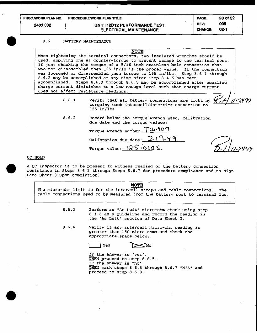
NOTE When tightening the 'terminal connectors, two insulated wrenches should be used. applying one as counter-torque to prevent damage to the terminal post. If just checking the torque of a 5/16 inch stainless bolt connection that was not disassembled then 125 in/lb is the proper value. If the connection was loosened or disassembled then torque to 165 in/lbs. Step 8.6.1 through 8.6.2 may be accomplished at any time after Step 8.4.6 has been accomplished. Steps 8.6.3 through 8.6.5 may be accomplished after equalize charge current diminishes to a low enough level such that charge current does not affect resistance readings.
8.6.1 Verify that all battery connections are tight by torquing each intercell/intertier connection to , 125 in/lbs
8.6.2 Record below the torque wrench used, calibration due date and the torque values:
Torque wrench number: TLb-Wq
PROCEDUREWORK PLAN TITLE:
UNIT 11 2D12 PERFORMANCE TEST ELECTRICAL MAINTENANCE
Calibration due date: a'\?-? 9 Torque value: I 2 S I ' i j L Q S .
PACiE: 20 d 52 REY: 005 CHANGE: 02-1
QC HOLD
A QC inspector is to be present to witness reading of the battery connection resistance in Steps 8.6.3 through Steps 8.6.7 for procedure compliance andto sign Data Sheet 3 upon completion.
NOTE The micro-ohm limit is for the intercell straps and cable connections. The cable connections need to be measured from the batten post to terminal lug.
8.6.3 Perform an "As Left. micro-ohm check using step 8.1.6 as a guideline and record the reading in the 'As Left" section of Data Sheet 3.
8.6.4 Verify if any intercell micro-ohm reading is greater than 150 micro-ohms and check the appropriate space below:
0 Yes IF the answer is "yes", - THEN proceed to step 8.6.5. IF the answer is "no', - THEN mark steps 8.6.5 through 8.6.7 "N/Am and proceed to step 8.6.8.

IF NOT, THEN mark the following steps N/A.
PROCmORK PIAN NO.
2403.002
-
A. Open disconnect switch 2D52.
B. Disassemble the affected connection(s) . &Ifi / C. Clean and neutralize the affected
connections using baking soda and water, ALL
8.6.5 - IF the answer to 8.6.4 was 'Yes', THEN perform the following; --
PROCEDUREWORK PLAN TITLE:
UNIT 11 2D12 PERFORMANCE TEST ELECTRICAL MAINTENANCE
then coat the connections Der C&D Manual
PAGE: 21 OI 52 REV: 005 CHANGE: 02-1
(TM C 173.0010) and reassemble
D. Torque the affected connections to 165 in/lbs.
E. Micro-ohm the affected connections. d!LL F. Record the micro-ohm readings of the
affected connections on Data Sheet flagging A
them as the second "As Left" reading. IF the second 'As Left" reading 3 - acceptable, THEN proceed to step 8.6.7. - IF the second 'As Left' reading is NOT - acceptable, THEN proceed to step 8.6.6.
8.6.6 IF the reading is still unacceptable, THEN perform the following. IF the reading is acceptable, %EN mark steps A through F "N/A" and proceed to - step 8.6.7.
A. Verify Disconnect Switch 2D52 is open. -Jd!L.L B. Replace the affected parts. flh / C. Clean and neutralize replacement parts and ,VJQ /
coat connections per C&D Manual (TM C 173.0010) and reassemble.
D. Torque connections to 165 in/lbs. ~ l d /
E. Obtain "As Left" resistance readings. ALL F. Record action taken and readings on the "As R)/h /
Left" comments section of Data Sheet 3.

8.6.7 Close Disconnect Switch 2D52
PROCNORK PLAN NO.
2403.002
8.6.8 Place the battery bank on Float charge and record the time. date and float voltage below:
Time and Date / S Y c /-3k99 lo at voltage 49,3Y VDC
PROCEDURVWORK PIAN TITLE:
UNIT 11 2D12 PERFORMANCE TEST ELECTRICAL MAINTENANCE
8.6.9 Perform 3 random specific gravity readings on the 2D12 battery bank, using procedure 2403.023 as a guide, to determine if stratification of these cells exist.
PAGE: 22 01 52 R N : 005 CHANGE: 02-1
A. IF stratification of the tested cells - -l--+-lyte exists, -----*-.
I mix the e1ect;olyte in each cell of the battery bank for 30 minutes on each cell, using a variable speed micro pump, with suction taken from the top of the cells throuqh the flame arrestor hole, and discharge through the sample.tube to the bottom of the cells; - -
IF NOT, THEN mark this step N/A. -
B. Perform all sections of Quarterly 2403.023. &+//-ZT- except the micro-ohm readings, and attach it to this procedure.
9.0 RESTOFATION AND CHECKOUT
9.1 - IF any Condition Reports were issued during the performance of this procedure,
LZ?? / / -24-69 THEN attach a copy of the Condition Report to this procedure; IF NOT -, THEN mark this step N/A.
9.2 Verify that the requirements of Housekeeping Level I1 have ~////-Z+W been met.
9.3 Verify that the measuring and test equipment have no known / 5 / / > - z q - 9 5 deficiency.
9 . 4 Verify with operations that 2D12 has been returned to its normal operation/lineup.
NOTE - 124.7 VDC is the Tech Spec value (lower limit) for a 58 cell bank's float voltage. However, the as left float voltage should be 127.6 to 130.5 when measured at the battery terminal.
9.5 Verify that the battery bank float voltage is between 127.6 &/ -2r -% and 130.5 VDC when on normal float charge.
I

I 2403.002 UNlT 11 2012 PERFORMANCE TEST ELECTRICAL MAINTENANCE
PROCJWORK PLAN NO.
9.6 Verify that all cell-to-cell and terminal connections are - / J - Z G ~ ? less than or equal to 150 mocro-ohms.
PROCEOURWORK P U N TITLE: PAGE: 23 O? 52 I
9.7 Verify that the battery log book has been updated to include the following:
9.7.1 Date this procedure was performed.
9.7.2 Time this procedure was started. d&// -2c- 5 7
9.7.3 Time this procedure was completed. 65' / I -2c-57
9.7.4 Any problems encountered and corrective action &#//-2q-?? taken.
9.7.5 Performer of this procedure. EN/ /-=-4y 9.8 Notify the Unit 2 Operations S/S that 2012 Performance 0 / / / - 2 ~ - 9
Discharge Test is complete.
9.9 Perform post-test check of torque wrenches on Torque Tester and record the following:
Equip. No. 77- 0 0 4 ~ a l . Due ~ a t e q / 3 / 4 4 Equip. No. Cal. Due Date-L-L- Et;/ / , -2-537
9.10 All setpoints and tolerances in this procedure have been checked and are verified to be within the specified and any exceptions are noted.
10.1 ATTACHMENTS
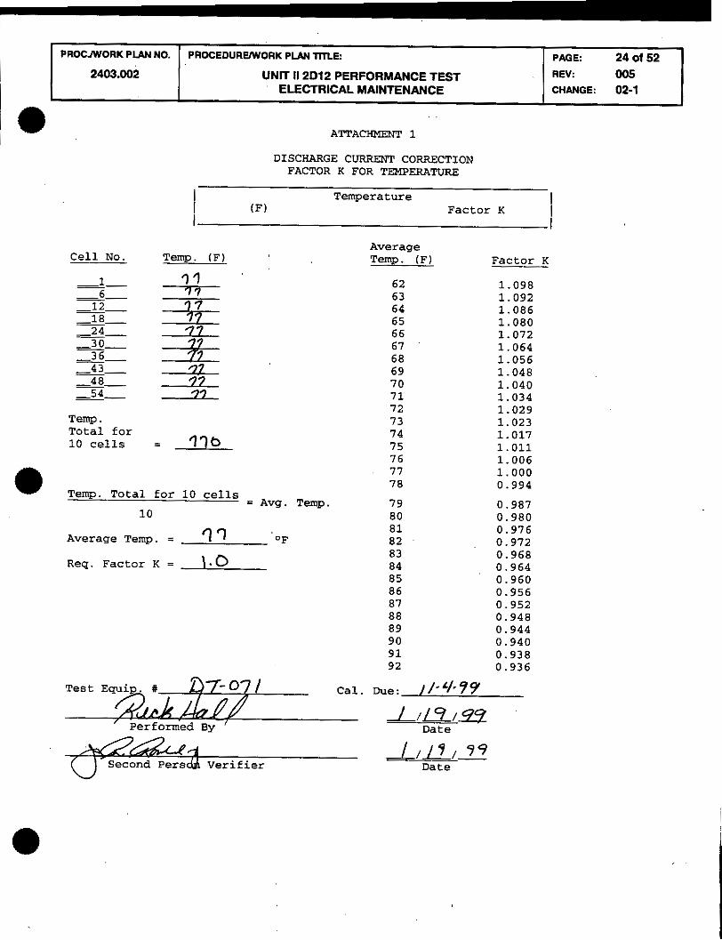
10.1.1 Attachment 1 - Discharge Current Correction K Factor For Temperature
10.1.2 Attachment 2 - Jumpering Low Voltage Cells 10.1.3 Attachment 3 - Calculation for Total Down Time 10.1.4 Data Sheet 1 - "As Found" Resistance 10.1.5 Datasheet 2 - Performance Discharge Test Battery Bank
Voltage
10.1.6 Data Sheet 3 - "As Left" Resistance
FORMS 10.2
10.2.1 None
ATTACHMENT 1
PROCNORK PLAN NO.
2403.002
DISCHARGE CURRENT CORRECTION FACTOR K FOR TEMPERATURE
I I
Temperature (F) Factor K
I I I I
Average Temp. (F) Temp. (F) Factor K
PROCEDUREWORK PLAN TITLE:
u ~ r r 11 2 ~ 1 2 PERFORMANCE TEST ELECTRICAL MAINTENANCE
77 1 . 0 0 0 7 8
Temp. Total for 1 0 cel ls 0.994
= Avg. Temp. 1 0
7 9 0.987 80 0 .980
Average Temp. = ? 7 81 OF
0.976 82 0.972
4
PAGE: 24 of 52 REV: 005 CHANGE: 02-1
Req. Factor K = 1.0
Cal. Due: / / - ' / ,99
///9/99 Date
Second ~ers& Verifier / 9 9
Date

ATTACHMENT 2 Page 1 of 5
PERFORMANCE TEST CELL JIIMPERING PROCEDURE
PROCJWORK PLAN NO.
2403.002
NOTE
This attachment provides a method to BY-PASS a low voltage cell. I
PROCEDUREWORK PLPH TITLE:
UNIT 11 2D12 PERFORMANCE TEST ELECTRICAL MAINTENANCE
NOTE Maintenance Engineering shall review Attachment 2 if attachment is required for procedure completion.
PAQE: 25 of 52 REV: 005 CHANGE: 02-1
NOTE
I A Second Person Verifier shall verify the content of steps 10, 11, and 15. I -----
Two - 250 mcm cables with 3/8 - 1/2 l G a b l e s approximate length is 10 feet will be needed for the cell jumpering. These are available in the Maintenance Facility Battery Storage Room.
1. Record the number of the cell(s) at or below 0.75 VDC, the Stop Time, the Cell Voltage and the Bank Voltage below and on Attachment 3.
Cell Number: Cell Voltage: Stop Time: Bank Voltage:
Cell Number: Cell V o l t a g e : Stop Time: Bank Voltage:
Cell Number: Cell V o l t a g e : Stop Time: Bank Voltage:
Cell Number: Cell Voltage: Stop Time: Bank Voltage:
NOTE At this time the Cognizant supervisorshall make the judgement to determine if the cell(s) should be jumpered or to continue the test with the cell(s) installed. This judgement should be based on Total Test Time, overall Bank Voltage, and the number of cells at or below 0.75 volts.
IF the Cognizant Supervisor's judgement is to continue the test with the 2. - cell (s) installed,
restart the discharge at the calculated current and record the restart time below and on Attachment 3. Continue recording data on Data Sheet 2 and discharge the bank until the bank voltage approaches 105 vdc, N/A Steps 3 through 11 of this attachment and continue with Step 12.
IF the Cognizant Supervisor's judgement is to jumper the cell(s), - THEN mark "Restart Time" below N/A and continue with Step 3. - Restart Time: 1- -
Cognizant Supervisor Date

ATTACHMENT 2 Page 2 of 5
PROCNORK PIAN NO.
2403.002
3. Open 2D52 Disconnect Switch.
Figure 1
PROCEDUREMTORK PLAN mLE:
UNIT I1 2D12 PERFORMANCE TEST ELECTRICAL MAINTENANCE
WARNING Jumpering, shorting or connecting the positive and negative lugs of a single cell may cause equipment damage or personnel injury.
PAGE: 26 of 52 REV: 005 CHANGE: 02-1
NOTE Jumpering of end cell may be accomplished by using the inter-tier or inter- bank cables.
a 4. Using Figure 1 as a guide only and presuming 'B" is the affected cell then remove bolts and intercell connection straps from the low voltage cell and its adjacent cell terminals.
NOTE Based on which is the low cell you may be jumpering the negative of A to the positive of C. As shown below in figure 2.

I PROCMORK PLAN NO. I PROCEDUREWORK PLAN mLE: I PAGE: 27 of 52 1
ATTACHMF.tiT 2 Page 3 of 5
2403.002
5. Bolt a (250 mcm) jumper from the left negative Battery A terminal / to the left positive Battery C terminal, using the same stainless bolts as used in the intercell connection straps.
6. Bolt another (250 mcm) jumper from the right negative Battery A ' / terminal to the right positive Battery C terminal, using the same
- stainless bolts as used in the intercell connection straps.
UNIT 11 2012 PERFORMANCE TEST ELECTRICAL MAINTENANCE
7. Torque terminal bolts to 165 in/lbs and record below the torque value and the recal date:
REV: 005 CHANGE: 02-1
Torque wrench number:
Torque value:
Recal Date:
8. Discharge the battery to a new voltage of
105 - (1.81 x # of Cells Jumpered) - new voltage Example :
105 - (1.81 x 1 cell ) = 103.19 M C
105 - (1.81 x 2 cells) = 101.38 VDC
105 - (1.81 x ) - New Discharge Voltage
SECOND PERSON VERIFIER 2
A Second Person Verifier shall verify the "New Discharge VoltageY in step 8 is correct.
- Second Person Verifier Date
9. Close 2D52 Disconnect Switch.
CAVTIMP
While discharging, continue to watch for cells falling below .75 M C .
10. Restart discharge at the new calculated current. 2

I 2403.002 I UNIT I1 2D12 PERFORMANCE TEST ELECTRICAL MAINTENANCE
PAGE: 28 of 52 REV. 005 CHANGE: 02-1
ATTACHMENT 2 Page 4 of 5
11. Record the restart time (below and on Attachment 3 1 , and battery terminal voltage after the load is applied:
Discharge started at Amps
Time restarted:
Overall battery terminal voltage VDC
SECOND PERSON VERIFIER
A Second Person Verifier shall verify step 11 was correctly completed.
1- - Second Person Verifier Date
12. Read and record in the last column of Data Sheet 2, the discharge battery overall bank voltage and cell voltages in the final moments before the minimum calculated voltage is reached.
13. Stop the test and de-energize the test equipment. Record the Stop Time on Attachment 3, on Data Sheet 2 and below:
Stop Time:
a 14. Open 2D52 disconnect switch.
15. Find the Down Time and old T, from Attachment 3 and use below to figure the New T,:
Old TI - Down Time - - New T, 2
SECOND PERSON VERIFIER
A Second Person Verifier shall verify the "New TAm in step 15 is correct.
1- - Second Person Verifier Date

PROCJWORK PIAN NO.
ATTACHMENT 2 Page 5 of 5
PROCEDURWORK PLAN TITLE: PAGE: 29 d 52 I 2403.002
16. IF cells were jumpered due to low voltage, THEN Engineering and the Cognizant Supervisor must be notified and 2 an evaluation made of cell condition prior to re-assembly of battery connections.
17. 2 cells were jumpered, THEN restore battery connections as follows:
UNIT 11 2D12 PERFORMANCE TEST ELECTRICAL MAINTENANCE
A . Clean and neutralize the affected connections using baking soda and water.
REV: 005 CHANGE: 02-1
B. Coat the connections per C&D Manual (TM C 173.0010) and / reassemble.
18. IF cells were jumpered, torque the connections to 165 in/lbs and record below the
torque value used and the recal date of the torque wrench used.
Torque wrench number:
Torque value: . . . . . . . . Calibration due date: '
19. 2 cells were jumpered, THEN micro-ohm the affected connections and record the affected - 2 connections on Data Sheet, flagging them as the second "As Left" reading.
20. Mark Steps 8.3.13 through 8.3.19 N/A and proceed with Step 8.3.20 /
NOTE - I ( Maintenance Engineering's signature is not needed to continue the work. 1
J 21. Plant Engineering has reviewed data of Attachment 2.
/ - Maintenance Engineering Date

ATTACHMENT 3
CALCULATION FOR TOTAL DOWN TIME
1. Start Time, Stop Time
(A) Start Time: (B) stop Time: 2 2 \0
(C) Start Time: (D) Stop Time:
(E) Start Time: (F) Stop Time:
( G ) Start Time: (H) Stop Time:
SECOND PERSON VERIFIER
PROCNYORK PLAN NO.
2403.002
A Second Person Verifier shall verify the "Start. Stop" time in step 1 is correct.
NOTE - The Total Down Time Calculation is for the Total Time the test is stopped for jumpering cellts), broken test equipment etc. The Final Stop Time (last stop time from above) shall not be used in the calculation.
Total Down Time
PROCEWRVWORK PLlW TITLE:
UNIT 11 2D12 PERFORMANCE TEST ELECTRICAL MAINTENANCE
Total Down Time (in minutes) = (C - B) + ( E - D) + (G - F)
PAGE: 30 Of 52 REV: 005 CHANGE: 02-1
Total Down Time - - - (in minutes) = (- ) + ( ) + ( ) =
I I
SECOND PERSON VERIFIER
A Second Person Verifier shall verify the 'Start. Stop' time in step I is correct.
1 -- Second Person Verifier Date
3. Old T, Calculation
Old T, = (A) - (Final Stop Time) Old T, =
SECOND PERSON VERIFIER
A Second Person Verifier shall verify calculations are correct in step 3.
L- Second Person Verifier Date

DATA SHEET 1
"AS FOUND"
PROCNYORK PLAN NO.
2403.002
Page 1 of 9
BATTERY BANK -'=-
PROCEDUREWORK P U N m E :
UNIT 11 2D12 PERFORMANCE TEST ELECTRICAL MAINTENANCE
RECORD RESISTANCE I IN MICRO-OHMS FOR I
-LISTED CONNECTIONS I -16~1-17Pll 16N2-17~21
-17~1-18~11 17N2-18~21 I
-18~1-19~11 18N2-19P21 I
- 19~1-20Pll 19N2-20~21 I 26 1 2 I
-21~1-22~11 21N2-22~21 I 23 2-7 1
- 22~1-23~11 22N2-23~21 2 5 / 1 2 I
-23~1-24~11 23N2-24~21
9 3 1 39 1 -24~1-25~11 24N2-25~21
27 1 24- 1 - 25~1-26Pl( 25N2-26~21
I 2 3 I
- 26~1-27~11 26N2-27P2
- 27~1-28~11 27N2-28~21
PAGE: 31 OI 5 2 REV: 005 CHANGE: 02-1
BATTERY RACk CELL TO CELI CONNECTIONI
16 - 17
BATTERY RACI CELL TO CELl -CONNECTION!
1 - 2
RECORD RESISTANCE I IN MICRO-OHMS FOR I

I PROCNVORK P M NO. I PROCEDUREWORK P M mLE: PAGE: 32 ot 52 I I UNIT 11 2D12 PERFORMANCE TEST
ELECTRICAL MAINTENANCE
DATA SHEET 1 Page 2 of 9 -
"AS FOUND" BATTERY BANK -=-
3ATTERY RACKI RECORD RESISTANCE I 3ELL TO CELL[ IN MICRO-OHMS FOR I -CONNECTIONS I -LISTED CONNECTIONS I
46~1-47~11 46~2-47~21 46 - 47 1 - 2 I
1 2403.002 I UNIT 11 2D12 PERFORMANCE TEST ELECTRICAL MAINTENANCE
PROCNYORK P U N NO. PAGE: 33 of 52 REV: 005 CHANGE: 02-1
PROCEDURVWORK P W TilLE:
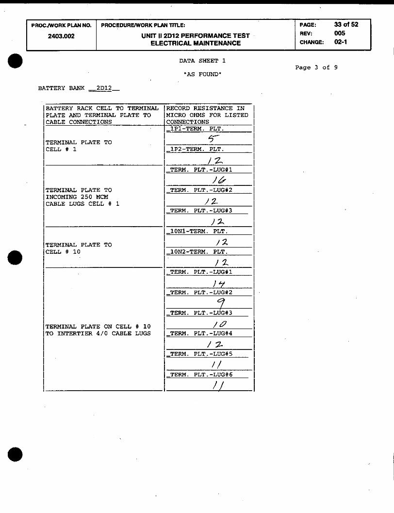
DATA SHEET 1
'AS FOUND'
BATTERY BANK -2D12
BATTERY RACK CELL TO TERMINAL IRECORD RESISTANCE IN I PLATE AND TERMINAL PLATE TO MICRO OHMS FOR LISTED I [CABLE CONNECTIONS CONNECTIONS
- I 1P1-TERM. PLT. I ! ! I TERMINAL PLATE TO !CELL # 1
I 5- I I !-~P~-TERM. PLT.
I !
I I I & I I TERMINAL PLATE TO I I -TERM. PLT. -LUG#2 I /INCOMING 250 MCM I I CABLE LUGS CELL # 1 12 I
I !-TERM. PLT. -LUG#3
I !
I I 12 I
I !-~ON~-TERM. PLT.
I I I TERMINAL PLATE TO CELL # 10
I / 2 I I 1 -10N2-TERM. PLT.
I I
I l y I I I-TERM. PLT. -LUG112
I I
0 I I / 1 -TERM. PLT . -~d~113 !
TERMINAL PLATE ON CELL # 10 1 1 0 TO INTERTIER 4/0 CABLE LUGS !-TERM. PLT.-LUG#4
I I
I I 1 -TERM. PLT . -LUG#6 !
Page 3 of 9

DATA SHEET 1 Page 4 of 9
'AS FOUND"
P AOE: 34 d 52 REV: 005 CHANGE: 02-1
PROCNVORK PLAN NO.
2403.002
BATTERY BANK -=-
PROCEDUREmORK P U N llll.E:
UNIT 11 2D12 PERFORMANCE TEST ELECTRICAL MAINTENANCE
BATTERY RACK CELL TO TERMINAL RECORD RESISTANCE IN I PLATE AND TERMINAL PLATE TO [MICRO OHMS FOR LISTED I CABLE CONNECTIONS CONNECTIONS
- I 11P1-TERM. PLT. I !
TERMINAL PLATE TO CELL # 11
/z I
I-I~PZ-TERM. PLT. I !
I / / I -TERM. PLT . -LUG#l
I I
I 5- I I /-TERM. PLT. -LUG#2 I I ' 5- I -TERM. PLT . -LUG113
i I I
TERMINAL PLATE ON CELL # 11 / 2- TO INTERTIER 4/0 CABLE LUGS - 1 TEPM. PLT.-LUG14 I
! I l Y I I TERM. PLT.-LUG#5
I !- ! I
13 I
I TERM. PLT.-LUG#6
I I- !
TERMINAL PLATE TO CELL # 20
I / y TERMINAL PLATE ON CELL 1) 20 TERM. PLT.-LUG#2
I I
/ / I I . , I !-TERM. PLT. -LUG#3 !

DATA SHEET 1
'AS FOUND'
---
BATTERY BANK -=- Page 5 of 9
PAGE: 35 of 52 REV: 005 CHANGE: 02-1
PROCJWORK PLAN NO.
2403.002
BATTERY RACK CELL TO TERMINAL PLATE AND TERMINAL PLATE TO W L E CONNECTIONS
PROCEDURVWORK PLAN TmE:
UNIT 11 2D12 PERFORMANCE TEST ELECTRICAL MAINTENANCE
TERMINAL PLATE ON CELL # 20 To INTERTIER 4/0 CABLE LUGS
TERMINAL PLATE TO CELL # 21
TERMINAL PLATE ON CELL # 21 TO INTERTIER 4/0 CABLE LUGS
TERMINAL PLATE TO CELL # 30
RECORD RESISTANCE IN I EtCRO OHMS FOR LISTED I ZONNECTIONS - TERM. PLT.-LUG#4
i I
1 / I I , . - TERM. PLT.-LUG#5 i
7 I - TERM. PLT.-LUG#6
I I
/ 2 - 21P1-TERM. PLT.
/ / I I - 21P2-TERM. PLT. I
- TERM. PLT.-LUG#l I /6 I
-TERM. PLT.-LUG112 I I
/& I - TERM. PLT.-LUG#3 I
1 3 I I - TERM. PLT.-LUG114 I
I 5 I I
- TERM. PLT.-LUG#5 I
- TERM. PLT.-LUG#6 1 ) D I
- 3ON1-TERM. PLT. I !
) / I
-3ON2-TERM. PLT. I

DATA SHEET 1
'AS FOUND"
-
BATTERY BANK -2D12-
PROCJWORK PLAN NO.
2403.002
BATTERY RACK CELL TO TERMINAL PLATE RND TERMINAL PLATE TO CABLE CONNECTIONS
PROCEDURWORK PLAN m L E :
UNIT 11 2D12 PERFORMANCE TEST ELECTRICAL MAINTENANCE
TERMINAL PLATE TO OUTGOING 250 MCM CABLE LUGS CELL # 30
PAGE: 36 d 52 REV: 005 CHANGE: 02-1
TERMINAL PLATE TO 2ELL # 31
TERMINAL PLATE TO INCOMING 250 MCM :ABLE LUGS CELL # 31
TERMINAL PLATE TO :ELL # 40
PERMINAL PLATE ON CELL # 40 l'0 INTERTIER 4/0 CABLE LUGS
RECORD RESISTANCE IN MICRO OHMS FOR LISTED I "NNECTIONS -TERM. PLT.-LUG#1
i !
I / I
-TERM. PLT.-LUG#2 I I
14 I - TERM. PLT.-LUGI13
I I
/L/ -31P1-TERM. PLT.
I I
/y I -31P2-TERM. PLT.
I I
4 - - TERM. PLT.-LUG#l
/ f i i - TERM. PLT.-LUG#2 I
/Y I -TERM. PLT.-LUG#3
I I
-40N1-TERM. _lL_l PLT . / 2
-40N2-TERM. PLT. I I
7) ! - TERM. PLT.-LUG#1 1
/&' I - TERM. PLT.-LUG#2
I I
$ I I
- TERM. PLT.-LUG#3 I 7 !
Page 6 of 9

I PROCNYORK PLAN NO. I P R O C E D U R ~ R K PLAN TITLE: PAGE: 37 ot 52 I I 2403.002 I UNIT 11 2D12 PERFORMANCE TEST REV:
ELECTRICAL MAINTENANCE CHANGE: 0°5 02-1 1
BATTERY BANK -=- BATTERY RACK CELL TO TERMINAL PLATE AND TERMINAL PLATE TO CABLE CONNECTIONS
TERMINAL PLATE ON CELL # 40 TO INTERTIER 4/0 CABLE LUGS
TERMINAL PLATE TO CELL # 41
TERMINAL PLATE ON CELL # 41 TO INTERTIER 4/0 CABLE LUGS
TERMINAL PLATE TO CELL # 50
TERMINAL PLATE CELL # 50 INTERTIER 4/0 CABLE LUGS
DATA SHEET 1
"AS FOUND"
RECORD RESISTANCE IN MICRO OHMS FOR LISTED CONNECTIONS -TERM. PLT.-LUG#5
/&' - TERM. PLT.-LUG#6
// -41P1-TERM. PLT.
i I
- 8
41P2-TERM. PLT. I I
1.5 I -TERM. PLT.-LUG#1
I I
18 I
- TERM. PLT.-LUG#2 - I
I / 7 I I
- TERM. PLT.-LUG#5
/ 7 -TERM. PLT.-LUG#6
I I
J 3 I -50N1-TERM. PLT.
/ 53 -50N2-TERM. PLT.
i I I
I4 -TERM. PLT.-LUG#1
I I
17 I -TERM. PLT.-LUG#2
I I
l I I I
Page 7 of 9

DATA SHEET 1 . Paae 8 of 9
PROCJWORK P U N NO.
2403.002
"AS FOUND"
BATTERY BANK -2D12- -
BATTERY RACK CELL TO TERMINAL RECORD RESISTANCE IN I JPLATE AND TERMINAL PLATE TO MICRO OHMS FOR LISTED I JCABLE CONNECTIONS
I [CONNECTIONS - I TERM. PLT.-LUG#3 I
I !
PROCEDUREWORK PLAN TITLE:
UNIT 11 2D12 PERFORMANCE TEST ELECTRICAL MAINTENANCE
I I I / I
I
I I-TERM. PLT.-LUG#4 I
I I
TERMINAL PLATE ON CELL # 50 1 / 4 I IT0 INTERTIER 4/0 CABLE LUGS TERM. PLT.-LUG#5 I
I I I- 4 1 I / -TERM . PLT . LUG# 6 I I /q I I-~IP~-TERM. PLT. I
i I TERMINAL PLATE TO CELL # 51 i -51P2-TERM. PLT. I I
I I
i 1 5- I
I I-TERM. PLT.-LUG#I I
I I
I I
I 1 / 3 1 1-TERM. PLT. -LUG#2
I I
I I / Y I 1-TERM. PLT. -LUG#3
I I I
I [TERMINAL PLATE ON CELL # 51 1 /TO INTERTIER 4/0 CABLE LUGS
I / 1-TERM. PLT. -LUG#4
I I
I I I / 5-
I 1 -TERM. PLT . -LUG115 I
I I / D I I -TERM. PLT. -LUG#6
i I I
I I ITERMINAL PLATE TO 1 CELL # 58
I ~ _ ~ ~ N ~ - T E R M . PLT.
I I I I
PAGE: 38 d 52 REV: 005 CHANGE: 02-1

PROCNORK P U N NO. PROCEDUREWORK PLPN TILE:
2403.002 UNIT 11 2D12 PERFORMANCE TEST ELECTRICAL MAINTENANCE
PAGE: 39 of 52 REV: 005 CHANGE: 02-1
-- - ~-
DATA SHEET 1
'AS FOUND"
BATTERY BANK -=- BATTERY RACK CELL TO TERMINAL ~RECORD RESISTANCE IN I PLATE AND TERMINAL PLATE TO (MICRO OHMS FOR LISTED I CABLE CONNECTIONS CONNECTIONS
1-TERM. PLT.-LUG#1 i I
I 1 7 I TERMINAL PLATE TO OUTGOING 250 MCM CABLE LUGS CELL #58
COMMENTS :
Test Equip. and Cal. Due. Date: Ln 0- ~o//5%3?7 /
I-, / /
/ -1 /
Performed by: .......... D-99 D te
Second Person Verifi &-%
QC Witnessed by: ... 9%-S, 7 Date
. ~ ._

DATA SHEET 2 Page 1 of 4
PROCmORK PLAN NO.
2403.002
Performance Discharge Test Battery Bank and Cell Voltages
Battery Bank 2D12 Start Time 1 3 5 7
I Cell l I 12 Hours l 13 ours l ' 14 Hours
PROCEDUREWORK P W mLE:
UNIT 11 2D12 PERFORMANCE TEST ELECTRICAL MAINTENANCE
Performed by 1 /- 20- 99 - Signature Date
PAGE: 40 ot52 REV: 005 CHANGE: 02-1

DATA SHEET 2 Page 2 of 4
PROCJWORK PLAN NO.
2403.002
Performance Discharge Test Battery Bank and Cell Voltages
Battery Bank
Performed by Signature Date
PROCEDUREWORK PLAN TmE:
UNIT 11 2D12 PERFORMANCE TEST ELECTRICAL MAINTENANCE
PAGE: 41 d 52 REV: 005 CHANGE: 02-1

PROCAVORK PLAN NO. PROCEDUREWORK PLAN l H U 5 PAGE: 42 of 52 1
DATA SHEET 2 Page 3 of 4
2403.002
Performance Discharge Test Battery Bank and Cell Voltages
Battery Bank 2D12
Performed by fd& ,6 - 1 / - 21 -99 Signature Date
UNIT 11 2D12 PERFORMANCE TEST ELECTRICAL MAINTENANCE
- NOTE -
Terminal voltage of 105 volts may be reached before a hour or % hour reading can be taken. Indicate the number of minutes past the hour or half hour above the column where the last reading was taken at test completion.
REV: 005 CHANGE: 02-1
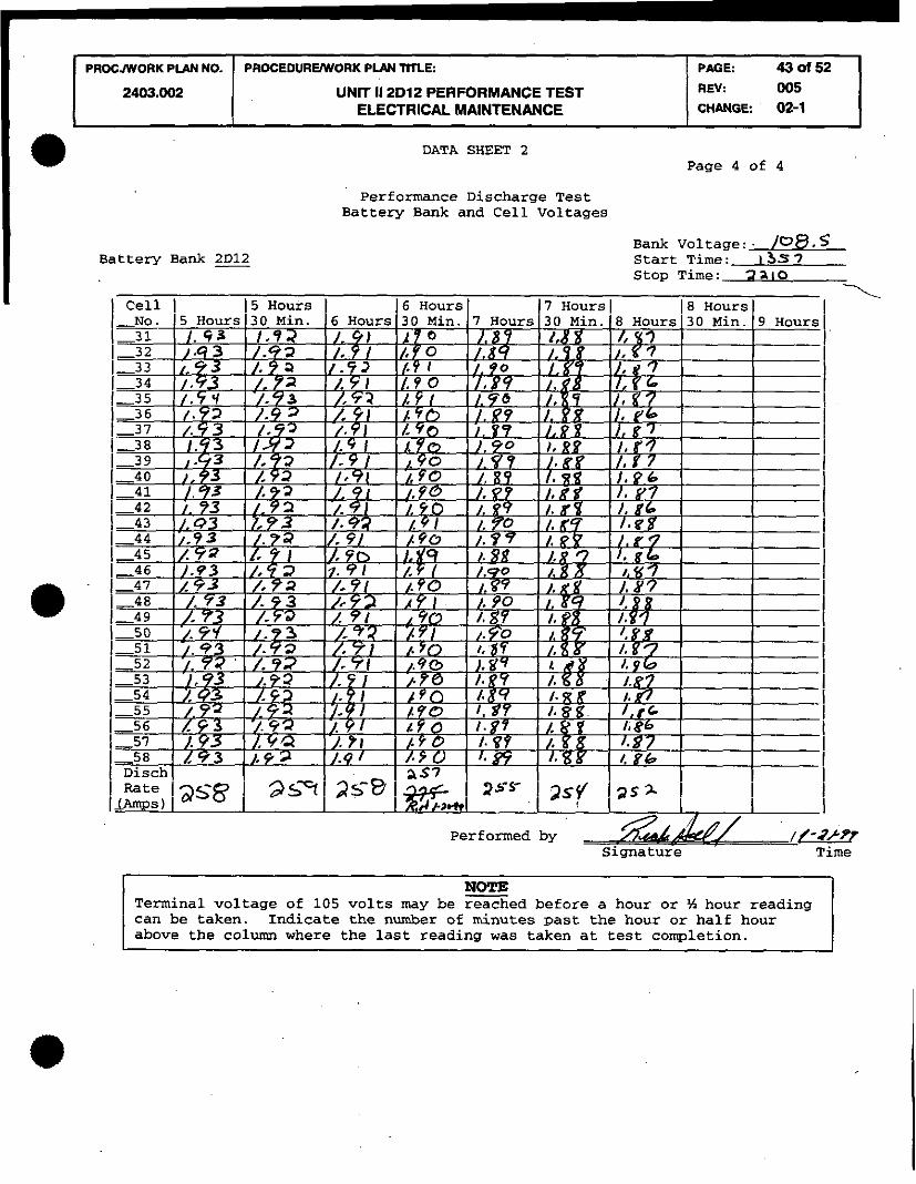
Performance Discharge Test Battery Bank and Cell Voltages
PROCAVORK PLAN NO.
2403.002
Battery Bank 2D12 Bank Voltage: . / ~ 8 . 5 Start Time: I 3s 7 Stop Time: 3 x 1 0
. -'. I
DATA SHEET 2 Page 4 of 4
PROCEDUREWORK PLAN llll-E:
UNIT 11 2D12 PERFORMANCE TEST ELECTRICAL MAINTENANCE
Performed by /- signature Time
PAGE: 43 of 52 REV: 005 CHANGE: 02-1
NOTE Terminal voltage of 105 volts may be reached before a hour or 5 hour reading can be taken. Indicate the number of minutes past the hour or half hour above the column where the last reading was taken at test cornletion.

PROCJWORK PLAN NO.
Page 1 of 9 "AS LEFT"
2403.002
BATTERY BANK -2D12 --
PROCEDUREWORK P M TllLE:
BATTERY RACK! RECORD RESISTANCE CELL TO CELL! IN MICRO-OHMS FOR
PAGE:
DATA SHEET 3
UNIT il2D12 PERFORMANCE TEST , ELECTRICAL MAINTENANCE
BATTERY RACK^ RECORD RESISTANCE I CELL TO CELL[ IN MICRO-OHMS FOR 1
'440152 1 REV: 005 CHANGE: 02-1

DATA SHEET 3
"AS LEFT"
PAGE: 45 oIS2 REV: 005 CHANGE: 02-1
PROCMORK P U N NO.
2403.002
BATTERY BANK -a-
PROCEDUREMTORK PLAN m L E :
UNIT 11 2D12 PERFORMANCE TEST ELECTRICAL MAINTENANCE
4TTERY RACK\ RECORD RESISTANCE I ELL TO CELL^ IN MICRO-OHMS FOR I ~ONNECTIONSI-LISTED CONNECTIONS I
31~1-32~11 31~2-32~21 31 - 32
1-32~1-33~1) 32~2-33~21 32 - 33
1-33~1-34~11 33N2-34~21 33 - 34
1-34~1-35~11 34N2-35~21 34 - 35
35 - 36
1-36~1-37~11 36~2-37~21
Page 2 of 9
ATTERY RACK^ RECORD RESISTANCE ELL TO CELL( IN MICRO-OHMS FOR CONNECTIONSI-LISTED CONNECTIONS
46~1-47~11 46N2-47P2 46 - 47
1-47~1-48~11 47N2-48P2 47 - 48 1 2 3 k 2 -
1-48~1-49~11 48N2-49P2

DATA SHEET 3
.AS LEFT"
PLPlN TITLE:
UNIT 11 2D12 PERFORMANCE TEST ELECTRICAL MAINTENANCE
BATTERY BANK -2D12-
PAGE: 46 of 52 R N : 005 CHANGE: 02-1
(BATTERY RACK CELL TO TERMINAL )RECORD RESISTANCE IN I PLATE AND TERMINAL PLATE TO IMICRO OHMS FOR LISTED I (CABLE CONNECTIONS CONNECTIONS
/ 1P1-TERM. PLT. I
I - I I I TERMINAL PLATE TO
(CELL # I I
I b I I I-1~2-TERM. PLT.
I I
'I ! i I I
I l- TERM. PLT.-LUG111 I
i TERMI IN^ PLATE TO INCOMING 250 MCM [CABLE LUGS CELL # I I i I I I I I I ON-T:. PLT. 1 I I \TERMINAL PLATE TO ]CELL # 10 1-10~2-TERM. PLT.
I I
i I I I I 1-TERM. PLT.-LUG#3 I I I (TERMINAL PLATE ON CELL # 10 1 I6 I IT0 INTERTIER 4/0 CABLE LUGS !-TERM. PLT.-LUG#4 I I
I I
I I 1-TERM. PLT.-LUG#5
I I I I I I 1-TERM. PLT.-LUG#6 I I I I
Page 3 of 9

1 PROCJWORK PLAN NO. I PROCEDUREWORK P U N mLE: 1 PffiE: 470152 1 UNIT 11 2D12 PERFORMANCE TEST
ELECTRICAL MAINTENANCE
DATA SHEET 3
"AS LEFT"
BATTERY BANK -=- ~BATTERY RACK CELL TO TERMINAL IRECORD RESISTANCE IN I PLATE AND TERMINAL PLATE TO /MICRO OHMS FOR LISTED I j CABLE CONNECTIONS 1 CONNECTIONS
- I 11P1-TERM. PLT. i I I I (TERMINAL PLATE TO 1 CELL # 11
I - I I ' I-~~P~-TERM. PLT.
I I
I I 81 I 1 TERM. PLT.-LUG#l 1 I I I 1-TERM. PLT.-LUG112 I
!- TERM. PLT.-LUG#3 I (TERMINAL PLATE ON CELL # 11 \.A\ [TO INTERTIER 4 / 0 CABLE LUGS I -TERM. -PLT. -LUG#4 !
I /
I I 20~1-TERM. PLT. 1 I TERMINAL PLATE TO /CELL # 20 1-2 0N2 -TERM. PLT . I I In
. -- ~TERMINAL PLATE ON CELL # 20 TERM. PLT.-LUG#2 /TO INTERTIER 410 CABLE LUGS 1- I
Q I
Page 4 of 9
1 I v ! !-TERM. PLT. -LUG#3 I

DATA SHEET 3
"AS LEFT"
BATTERY BANK -=-
PAGE: 48 ot 52 REV: 005 CHANGE: 02-1
PROCmORK PIAN NO.
2403.002
3ATTERY RACK CELL TO TERMINAL IRECORD RESISTANCE IN I PLATE AND TERMINAL PLATE TO IMICRO OHMS FOR LISTED (
PROCEDUREWORK PLAN TITLE:
UNIT 11 2D12 PERFORMANCE TEST ELECTRICAL MAINTENANCE
:ABLE CONNECTIONS CONNECTIONS I TERM. PLT.-LUG#4 I - ! I / - 7 I
TERMINAL PLATE ON CELL # 20 1-TERM. PLT.-LUG#5 r0 INTERTIER 4/0 CABLE LUGS I
I 9 I
TERMINAL PLATE TO CELL # 21
' Y I I 1-21~2-Ty. PLT. I I
TERMINAL PLATE ON CELL # 21 I TO INTERTIER 4/0 CABLE LUGS [-TERM. PLT.-LUG#4
I !
I 1- 30N1-TERM. PLT. 1 I rl I
TERMINAL PLATE TO CELL # 30
i I ~-~ON~-TERM. PLT.
I I I
Page 5 of 9

1 PRmlwMTORK PLAN NO. I PROCEDURENORK PLAN TmE:
DATA SHEET 3
'AS LEFT"
PAGE: 49 ot 52 . . .- -- . . - . -
2403.002
BATTERY BANK -2DJ.2-
I
3ATTERY RACK CELL TO TERMINAL 'LATE AND TERMINAL PLATE TO :ABLE CONNECTIONS
TERM. PLT.-LUG#l I
I- I Y !
UNIT 11 2D12 PERFORMANCE TEST ELECTRICAL MAINTENANCE
. - PERMINAL PLATE TO 1-TERM. PLT.-LUG#2 I IUTGOING 250 MU4 :ABLE LUGS CELL # 30 "(1 I
1-TERM. PLT.-LUG#3 !
REV. 005 CHANGE: 02-1
1-31P1-TERM. PLT. I TERMINAL PLATE TO
I :ELL # 31
I 8 1-31P2-TERM. PLT. I .
. - FERMINAL PLATE TO 1-TERM. PLT.-LUG#2 INCOMING 250 MCM
I CABLE LUGS CELL # 31
I /8 I I 1-TERM. PLT.-LUG#3
I I
I b I I 1-40~1-TERM. PLT.
I I h
I I
TERMINAL PLATE TO CELL # 40
I ?3 I -~ONZ-TERM. PLT .
i I l-7
I I
TERM. PLT.-LUG#l -1-1
I TERMINAL PLATE ON CELL # 40 1 / 15 TO INTERTIER 4/0 CABLE LUGS 1-TERM. ~LT.- LUG#^
i I a A
I I
Page 6 of 9

DATA SHEET 3
'AS LEFT'
PAGE: 50 of 52 REV: 005 CHANGE 02-1
PROCJWORK P U N NO.
2403.002
BATTERY BANK -=- I
PROCEDURWRK PLBN TmE:
UNIT II 2D12 PERFORMANCE TEST ELECTRICAL MAINTENANCE
1ERMINAL PLATE ON CELL # 40 ( / ( 10 INTERTIER 4/0 CABLE LUGS !-TERM. PLT.-LUG#6 !
IATTERY RACK CELL TO TERMINAL IRECORD RESISTANCE IN I
I /o I I I-~~PI'-TERM. PLT. I P
I I
'LATE AND TERMINAL PLATE TO !ABLE CONNECTIONS
:ERMINAL PLATE TO 3 :ELL # 41 I
MICRO OHMS FOR LISTED I CONNECTIONS
I . I
TERM. PLT.-LUG#l I
I- !
- I TERM. PLT.-LUG#5 I !
'ERMINAL PLATE ON CELL # 41 :O INTERTIER 4/0 CABLE LUGS !-TERM. PLT.-LUG#4
1-TERM. PLT. -LUE#6 ! i 1 A I-~ON~-TERM. PLT.
I I - I
I
TERMINAL PLATE TO CELL # 50
i 5 1-50~2-TE~. PLT.
I U
I - TERM. PLT.-LUG#1 . m i TERMINAL PLATE CELL 1) so i / 5 INTERTIER 4/0 CABLE LUGS TERM. PLT.-LUG#2 I I- .? I
Page 7 of 9

DATASHEET 3
I
Page 8 of 9
I
"AS LEFT"
BATTERY BANK -2D12- -
BATTERY RACK CELL TO TERMINAL (RECORD RESISTANCE IN I PLATE AND TERMINAL PLATE TO MICRO OHMS FOR LISTED 1 CABLE CONNECTIONS CONNECTIONS
(-TERM. PLT.-LUG#3 I I
- - I - - - .
PROCmORK PIAN NO.
2403.002
I/// (-TERM. PLT.-LUG#4 I
r E m m u PUTE ON c n L r 50 I 8 I TO INTERTIER 4/0 CABLE LUGS 1-TERM. PLT.-LUG#5 I
I 4 !
I V I-~~P~-TERM. PLT.
I
PERMINAL PLATE TO I I 6 I
:ELL # 51 ~ - ~ ~ P ~ - T E R M . PLT. I
I <- I I
PROCEDUREMORK PLbN TILE:
UNIT 11 2D12 PERFORMANCE TEST ELECTRICAL MAINTENANCE
I I 1s I TERM. PLT.-LUG#2
I ! - !
PAGE: 51 of 52 REV: 005 CHANGE: 02-1
I L 1 !-TERM. PLT . -LUG# 3 !
?ERMINAL PLATE ON CELL # 51 ?O INTERTIER 4/0 CABLE LUGS
I 1 / I
1 -TERM. PLT. -LUG04 I I
IQI ! - TERM. PLT.-LUG#6 I 1 1 6 1 I-~~N~-TERM. PLT.
I 'ERMINAL PLATE TO 'ELL # 58 I-I I-~~NZ-TERM. PLT. I
I PROCNYORK P U N NO. ( PROCEDUREWORK PLPH TITLE: PAGE: 52 d 52 I UNIT 11 2D12 PERFORMANCE TEST
ELECTRICAL MAINTENANCE
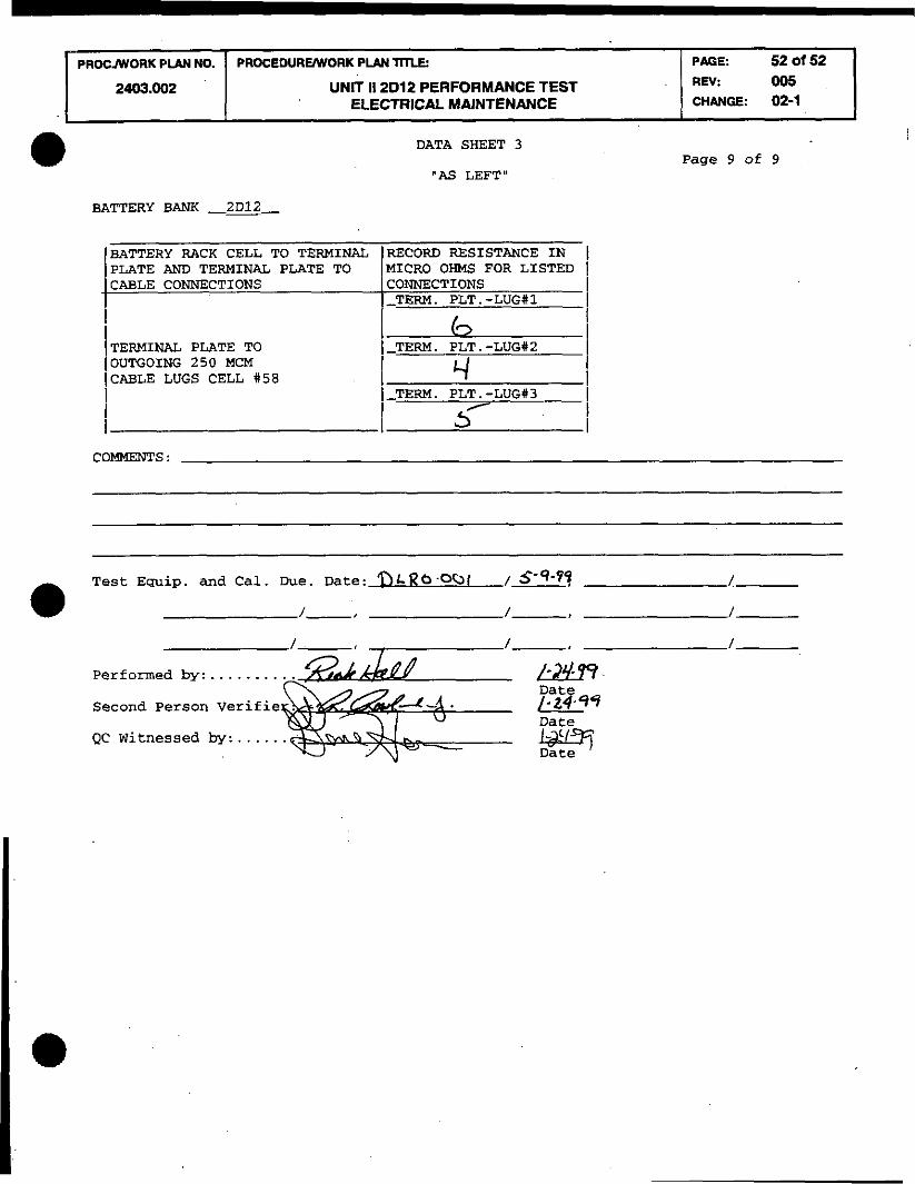
DATA SHEET 3
"AS LEFT"
BATTERY BANK _2012
/BATTERY RACK CELL TO TERMINAL IRECORD RESISTANCE IN I /PLATE AND TERMINAL PLATE TO MICRO OHMS FOR LISTED I CABLE CONNECTIONS CONNECTIONS
!-TERM. PLT.-LUG#I I !
i (TERMINAL PLATE TO
I lOUTGOING 250 MCM (CABLE LUGS CELL #58
kTERM. : I 7
I
Page 9 of 9
COMMENTS :
........ Performed by: k2.m Date
Second Person Verifie /-2499
. . . . . . QC Witnessed by: