Embed Size (px)
Citation preview

GE Grid AutomationEducation Seminar for Industries

2
GE Multilin Contacts
• Eduardo Iglesias, Regional Sales Manager305-898-6539, [email protected]
• Mike Ramlachan, Technical Application Engineer 201-780-6601 [email protected]
• Terrence Smith, Technical Application Director423-304-0843, [email protected]

GE Digital Energy Multilin:
Motor Protective Relay Offerings
GE Digital Energy MultilinMotor Protection Relay Offerings
Low VoltageMM200/MM300
Medium Voltage339
Medium Voltage369
Medium Voltage869
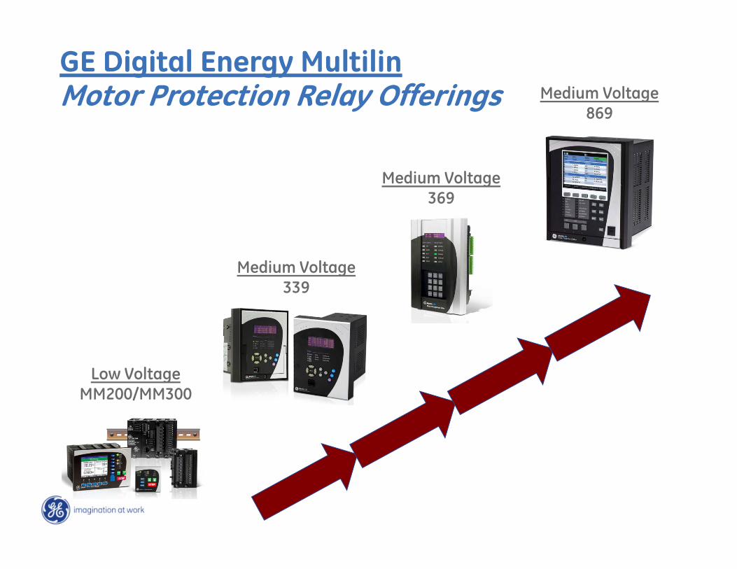
Key Differences – Low Voltage Motor Protection
Feature
MM200 MM300
Warranty (years) 10 10Hardware Din Rail Din Rail or Panel MountDisplay Opt Status & Control Opt Status & Control, Opt Graphic Display w/ USBContact Inputs/Outputs 7/3 6/2 std, 24/16 optHarsh Conformal Coating Std StdNetwork Options No Opt 10/100MB Copper RJ45 – Modbus TCP/IP
RS485 Port 1 – Modbus, 1 – Profibus or DeviceNet 1 – Modbus, Opt – Profibus or DeviceNetDeviceNet or Profibus Yes Yes
Front USB Port w/ Opt HDD Display w/ Opt Graphic Display, w/ Opt HDD DisplayWaveform (samples / cycle) No 32 - OptCounters Trips, Starts, Running & Stopped Hours Trips, Starts, Running & Stopped HoursEvent Recorder No Opt – 256 EventsPower Metering No Yes, Opt 3 Phase VoltageLearned Data Acceleration Time, Starting Current,
Starting TCUAcceleration Time, Starting Current, Starting TCU
RTD Inputs No Up to 6 OptProgrammable Logic No OptProgrammable LEDs Yes YesStarter Types FVNR, FVR, Two Speed FVNR, FVR, Two Speed, Wye Delta, Soft Start, Inverter
Standard Functions Thermal Overload, Under Current, Current Unbalance, Mechanical Jam, Ground Fault37UC, 46, 49, 50G, 50LR, 50M, 51G, 66, 86
Thermal Overload, Under Current, Current Unbalance, Mechanical Jam, Ground Fault
37UC, 46, 49, 50G, 50LR, 50M, 51G, 66, 86Optional Functions N/A Underpower, Phase Overvoltage / Undervoltage, Auxiliary Undervoltage, Phase
Reversal, VT Fuse Failure, RTD Overtemperature, Undervoltage Restart37UP, 38, 27P, 27Aux, 47. 59
Internal CTs 5A FLA, 2 or 3 CT connection 5A FLA, 2 or 3 CT connectionData Logger No OptTime Sync No Opt SNTP
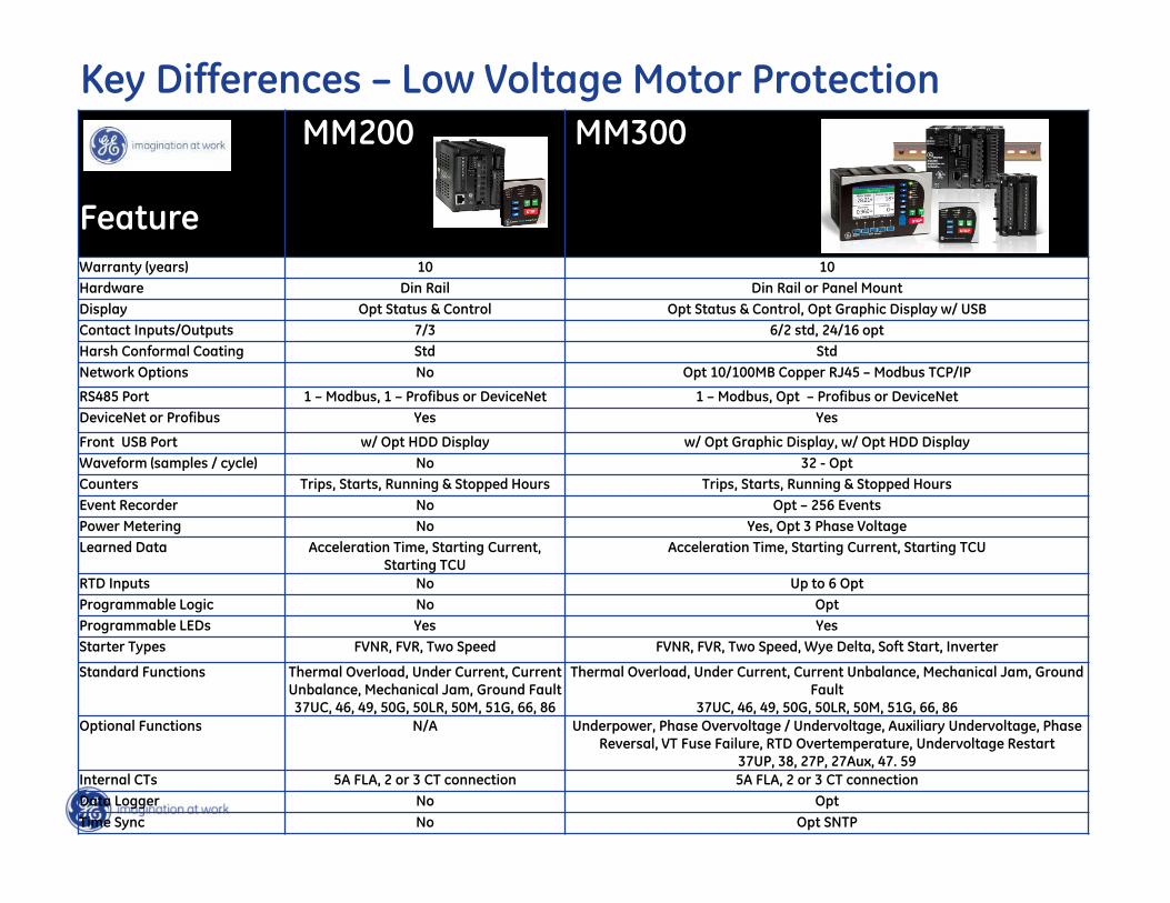
Key Differences – Medium Voltage Motor Protection
Feature
339 369 869
Warranty (years) 10 10 10Hardware Draw-out or Fixed Fixed Draw-outDisplay LCD LCD ColorContact Inputs/Outputs 10/6 6/4 7/5 Std, 7/5 OptHarsh Conformal Coating Opt Opt StdRemovable Power Supply No No Yes (no Electrolytic Capacitors)Network Options 100MB Copper RJ45 and Fiber
Optic MTRJ - Opt10MB Copper RJ45 100MB Copper RJ45 Std,
Dual Fiber Optic ST – Opt, WiFi - Opt
RS485 Port 1 2 Std, 1 Opt 1Modbus Serial and TCP/IP Yes Yes YesIEC61850 GOOSE Opt Copper & Fiber Optic Ethernet No Opt - Fiber Ethernet only
Front USB Port Yes No YesWaveform (samples / cycle) 32 16 128Current and Voltage Harmonics No No Yes (up to 25th)Power Metering Opt Opt YesdcMA Inputs No No 4 Opt – June 2015dcMA Outputs No 1 Std, 3 Opt 7 Opt – June 2015RTD Inputs Opt – up to 12 with RMIO 12 Opt 6-12 OptProgrammable Logic Logic Elements No OptProgrammable LEDs Opt No YesStandard Functions 14, 37, 46, 48, 49, 50P, 50N, 50G,
50LR, 50M, 50BF, 51G, 66, 8614, 19, 37, 46, 49, 50P, 50G, 50LR, 50M, 51P, 51G, 66, 86
14, 19, 37, 46, 49, 50P, 50N, 50G, 50_2, 50LR, 50M, 50BF, 51P, 51N, 51G, 66, 86
Optional Functions 27P/47/59P/59_2/81/VTFF 38, 27P/32/47/55/59/81 38, 27P/47/59P/59N/59X/81/VTFF, 32/55/59_2, 67P/67N/87
Broken Rotor Bar No No OptData Logger No Yes YesMotor Start/Stop Report Yes Yes YesTime Sync IRIG-B, SNTP No IRIG-B, SNTP (opt) & IEEE 1588 (opt)

AC Motor Protection Fundamentals
Motor Electrical Protection
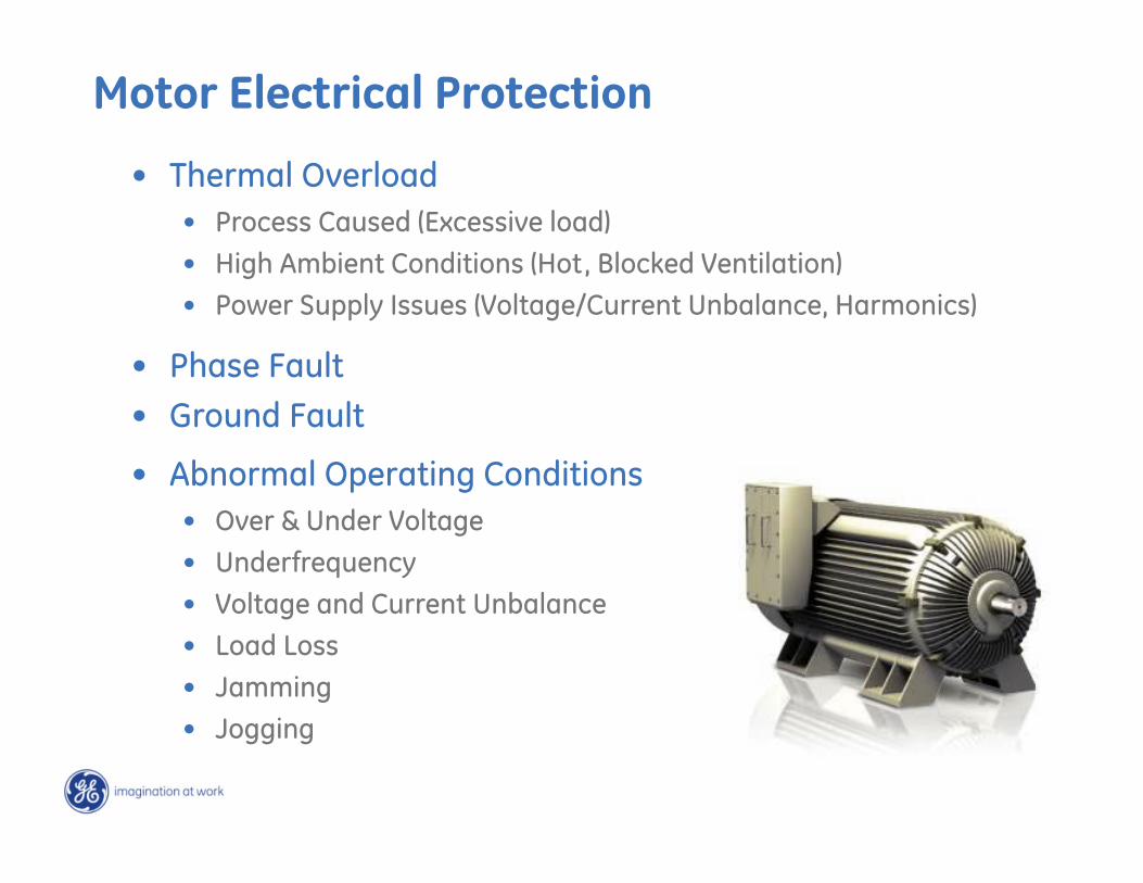
• Thermal Overload• Process Caused (Excessive load)• High Ambient Conditions (Hot, Blocked Ventilation)• Power Supply Issues (Voltage/Current Unbalance, Harmonics)
• Phase Fault• Ground Fault
• Abnormal Operating Conditions• Over & Under Voltage• Underfrequency• Voltage and Current Unbalance• Load Loss• Jamming• Jogging
Risks for an Overheated Motor
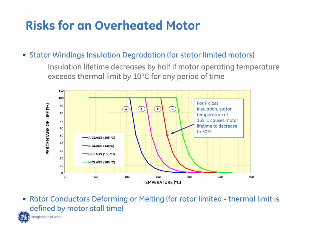
• Stator Windings Insulation Degradation (for stator limited motors)
Insulation lifetime decreases by half if motor operating temperature exceeds thermal limit by 10ºC for any period of time
0
10
20
30
40
50
60
70
80
90
100
110
0 50 100 150 200 250 300
TEMPERATURE (ºC)
PERC
ENTA
GE
OF
LIFE
(%)
A-CLASS (105 ºC)
B-CLASS (130ºC)
F-CLASS (155 ºC)
H-CLASS (180 ºC)
A B F H
For F class insulation, stator temperature of 165ºC causes motor lifetime to decrease to 50%
• Rotor Conductors Deforming or Melting (for rotor limited - thermal limit is defined by motor stall time)
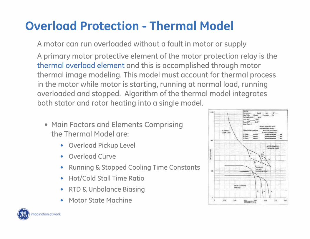
A motor can run overloaded without a fault in motor or supply
A primary motor protective element of the motor protection relay is the thermal overload element and this is accomplished through motor thermal image modeling. This model must account for thermal process in the motor while motor is starting, running at normal load, running overloaded and stopped. Algorithm of the thermal model integrates both stator and rotor heating into a single model.
• Main Factors and Elements Comprisingthe Thermal Model are:
• Overload Pickup Level
• Overload Curve
• Running & Stopped Cooling Time Constants
• Hot/Cold Stall Time Ratio
• RTD & Unbalance Biasing
• Motor State Machine
Overload Protection - Thermal Model
Thermal Model - Motor States
• Motor Stopped:Current < “0” threshold & contactor/breaker is open.
• Motor Starting: Previous state is “Stopped” & Current > “0” threshold. Motor current must increase to the level higher than overload pickup within seconds otherwise motor algorithm will declare the “Running” state.
• Motor Running: Previous state is “Starting” or “Overloading” & Current drops below overload pickup level.
• Motor Overloading: Previous state is “Running” & Current raises above overload pickup level. Thermal Capacity Used (TCU) begins to accumulate
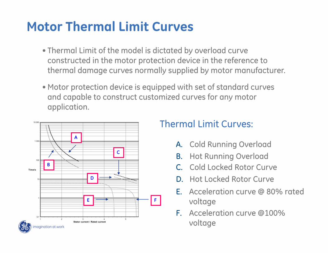
Motor Thermal Limit Curves
Thermal Limit Curves:
B. Hot Running OverloadB
A. Cold Running OverloadA
D. Hot Locked Rotor CurveD
C
C. Cold Locked Rotor Curve
F. Acceleration curve @100% voltage
FE. Acceleration curve @ 80% rated
voltageE
• Thermal Limit of the model is dictated by overload curve constructed in the motor protection device in the reference to thermal damage curves normally supplied by motor manufacturer.
• Motor protection device is equipped with set of standard curves and capable to construct customized curves for any motor application.
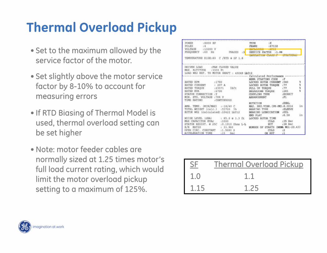
Thermal Overload Pickup
• Set to the maximum allowed by the service factor of the motor.
• Set slightly above the motor service factor by 8-10% to account for measuring errors
• If RTD Biasing of Thermal Model is used, thermal overload setting can be set higher
• Note: motor feeder cables are normally sized at 1.25 times motor’s full load current rating, which would limit the motor overload pickup setting to a maximum of 125%.
SF Thermal Overload Pickup1.0 1.11.15 1.25
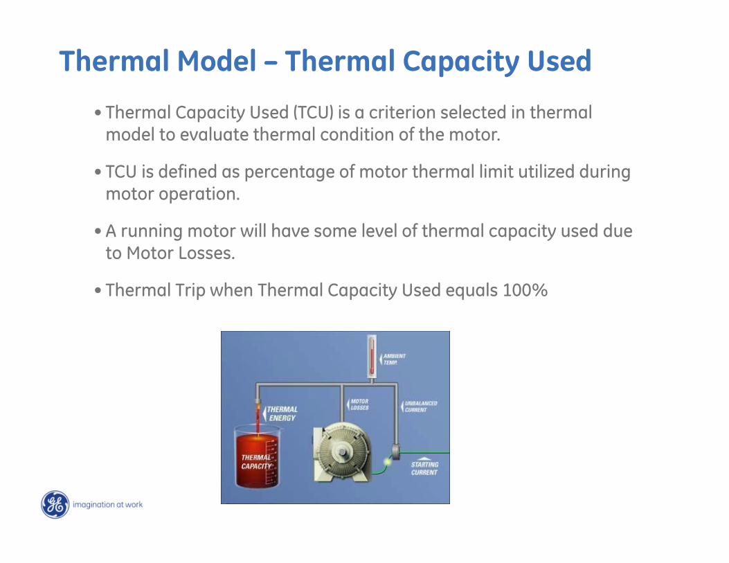
• Thermal Capacity Used (TCU) is a criterion selected in thermal model to evaluate thermal condition of the motor.
• TCU is defined as percentage of motor thermal limit utilized during motor operation.
• A running motor will have some level of thermal capacity used due to Motor Losses.
• Thermal Trip when Thermal Capacity Used equals 100%
Thermal Model – Thermal Capacity Used
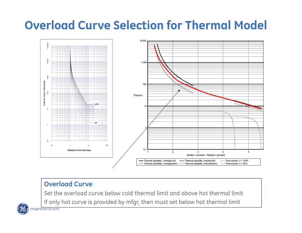
Overload CurveSet the overload curve below cold thermal limit and above hot thermal limitIf only hot curve is provided by mfgr, then must set below hot thermal limit
Overload Curve Selection for Thermal Model
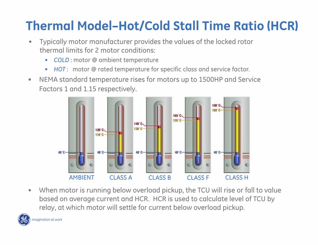
Thermal Model–Hot/Cold Stall Time Ratio (HCR)• Typically motor manufacturer provides the values of the locked rotor
thermal limits for 2 motor conditions: • COLD : motor @ ambient temperature• HOT : motor @ rated temperature for specific class and service factor.
• When motor is running below overload pickup, the TCU will rise or fall to value based on average current and HCR. HCR is used to calculate level of TCU by relay, at which motor will settle for current below overload pickup.
• NEMA standard temperature rises for motors up to 1500HP and Service Factors 1 and 1.15 respectively.
AMBIENT CLASS A CLASS B CLASS F CLASS H
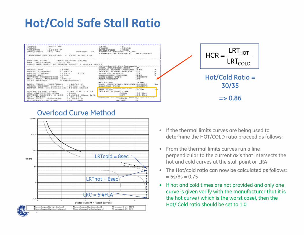
Hot/Cold Ratio = 30/35
=> 0.86
Hot/Cold Safe Stall Ratio
COLD
HOT
LRTLRT
HCR
• If the thermal limits curves are being used to determine the HOT/COLD ratio proceed as follows:
• From the thermal limits curves run a line perpendicular to the current axis that intersects the hot and cold curves at the stall point or LRA
• The Hot/cold ratio can now be calculated as follows: = 6s/8s = 0.75
• If hot and cold times are not provided and only one curve is given verify with the manufacturer that it is the hot curve ( which is the worst case), then the Hot/ Cold ratio should be set to 1.0
LRC = 5.4FLA
LRTcold = 8sec
LRThot = 6sec
Overload Curve Method
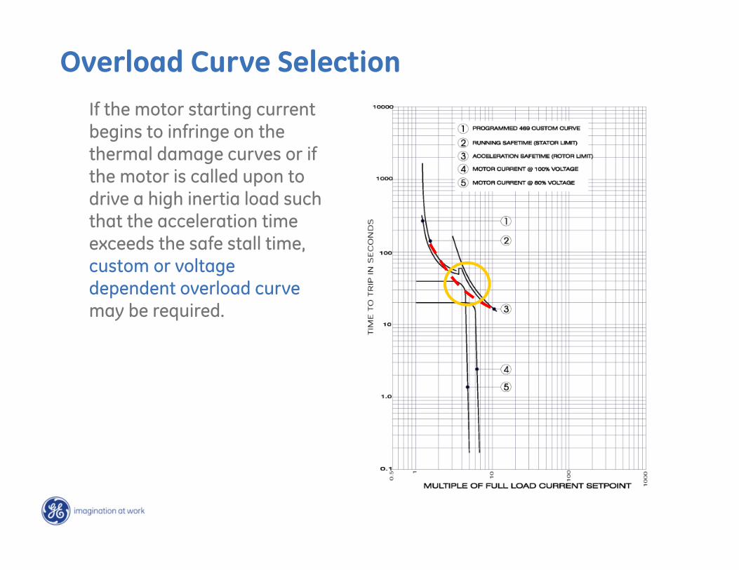
If the motor starting current begins to infringe on the thermal damage curves or if the motor is called upon to drive a high inertia load such that the acceleration time exceeds the safe stall time, custom or voltage dependent overload curvemay be required.
Overload Curve Selection
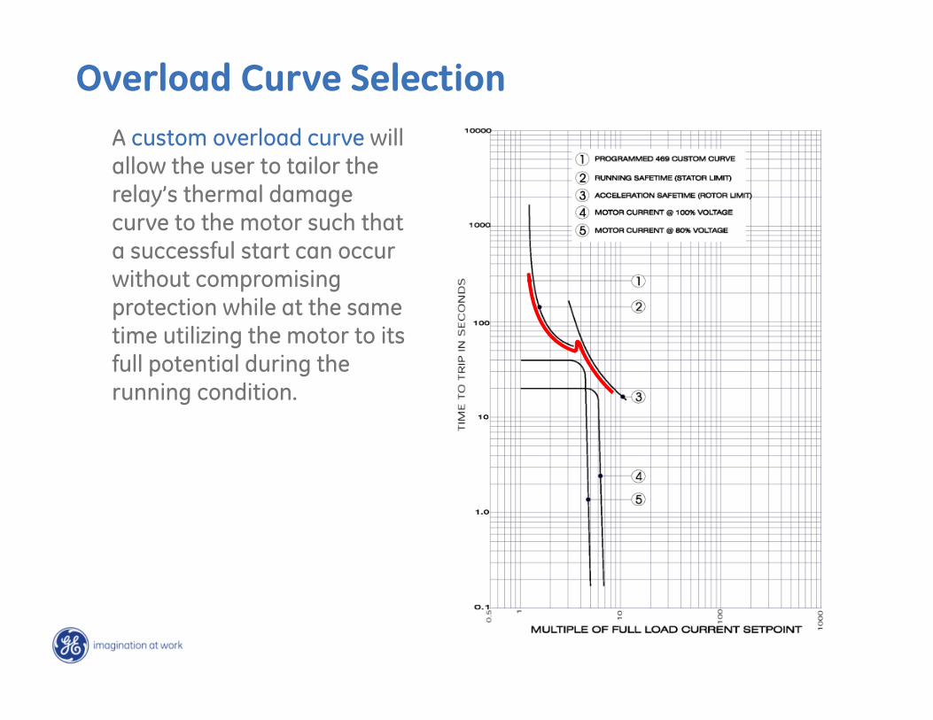
Overload Curve SelectionA custom overload curve will allow the user to tailor the relay’s thermal damage curve to the motor such that a successful start can occur without compromising protection while at the same time utilizing the motor to its full potential during the running condition.
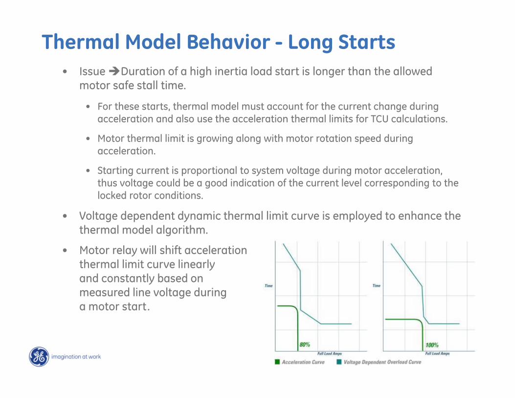
Thermal Model Behavior - Long Starts• Issue Duration of a high inertia load start is longer than the allowed
motor safe stall time.
• For these starts, thermal model must account for the current change during acceleration and also use the acceleration thermal limits for TCU calculations.
• Motor thermal limit is growing along with motor rotation speed during acceleration.
• Starting current is proportional to system voltage during motor acceleration, thus voltage could be a good indication of the current level corresponding to the locked rotor conditions.
• Voltage dependent dynamic thermal limit curve is employed to enhance the thermal model algorithm.
• Motor relay will shift accelerationthermal limit curve linearlyand constantly based onmeasured line voltage duringa motor start.
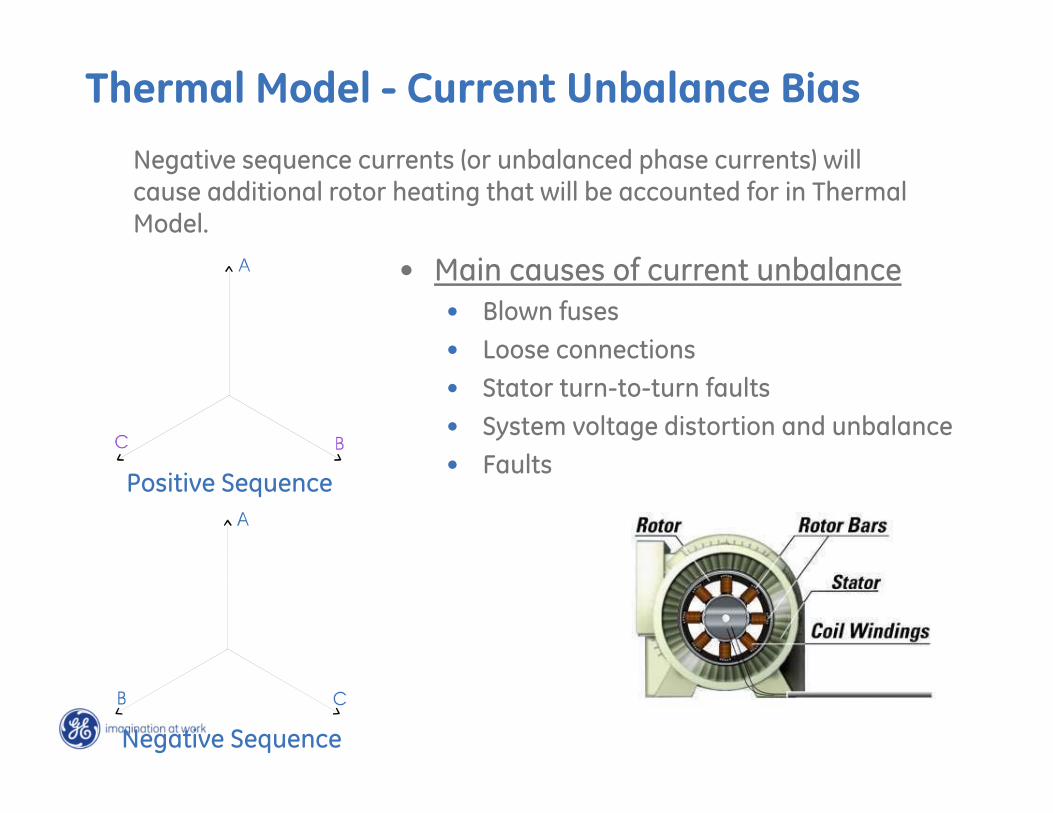
Thermal Model - Current Unbalance BiasNegative sequence currents (or unbalanced phase currents) will cause additional rotor heating that will be accounted for in Thermal Model.
Positive Sequence
Negative Sequence
• Main causes of current unbalance• Blown fuses• Loose connections• Stator turn-to-turn faults• System voltage distortion and unbalance• Faults
Thermal Model - Current Unbalance Bias
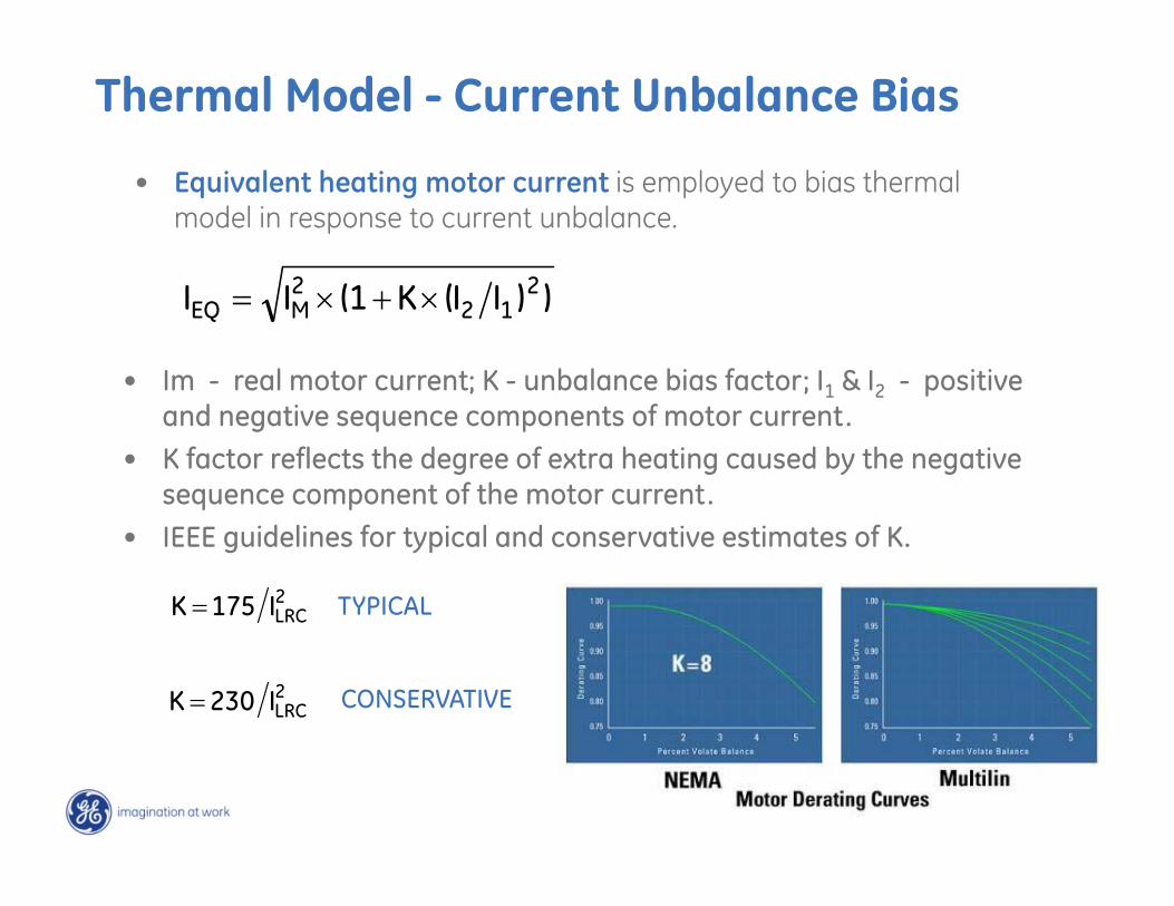
• Equivalent heating motor current is employed to bias thermal model in response to current unbalance.
))II(K(1II 212
2MEQ
• Im - real motor current; K - unbalance bias factor; I1 & I2 - positive and negative sequence components of motor current.
• K factor reflects the degree of extra heating caused by the negative sequence component of the motor current.
• IEEE guidelines for typical and conservative estimates of K.
2LRCI175K TYPICAL
2LRCI230K CONSERVATIVE
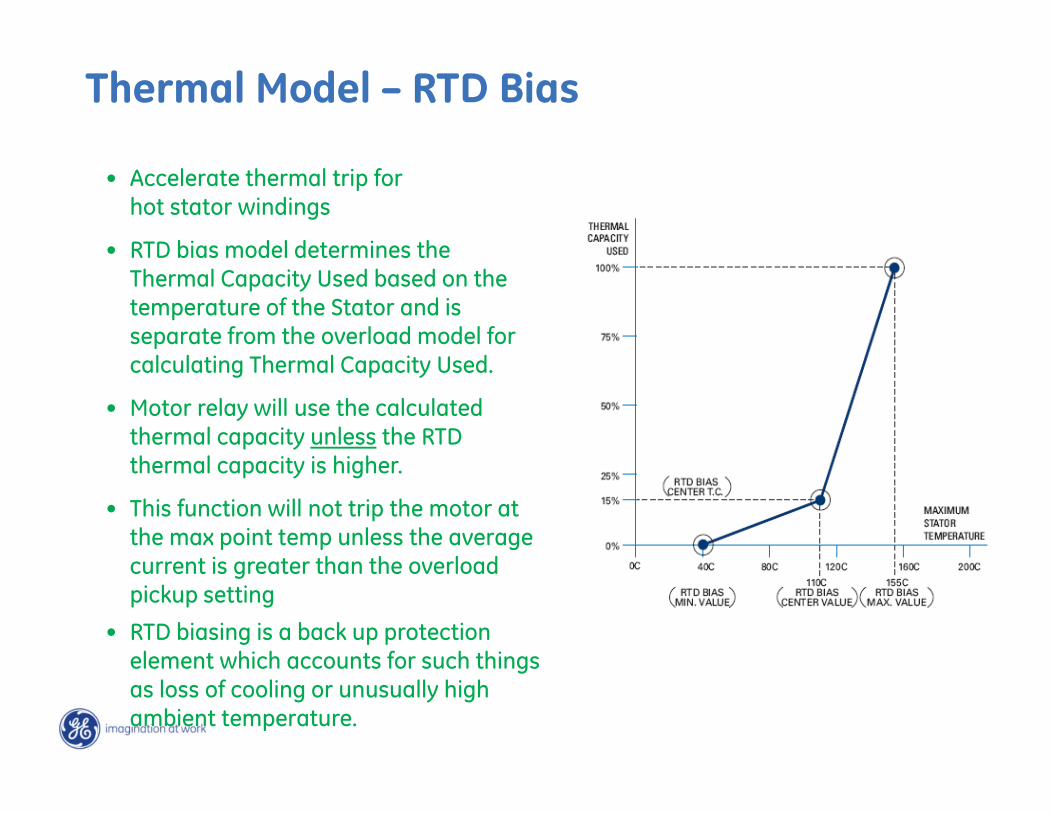
• Accelerate thermal trip for hot stator windings
• RTD bias model determines the Thermal Capacity Used based on the temperature of the Stator and is separate from the overload model for calculating Thermal Capacity Used.
• Motor relay will use the calculated thermal capacity unless the RTD thermal capacity is higher.
• This function will not trip the motor at the max point temp unless the average current is greater than the overload pickup setting
• RTD biasing is a back up protection element which accounts for such things as loss of cooling or unusually high ambient temperature.
Thermal Model – RTD Bias
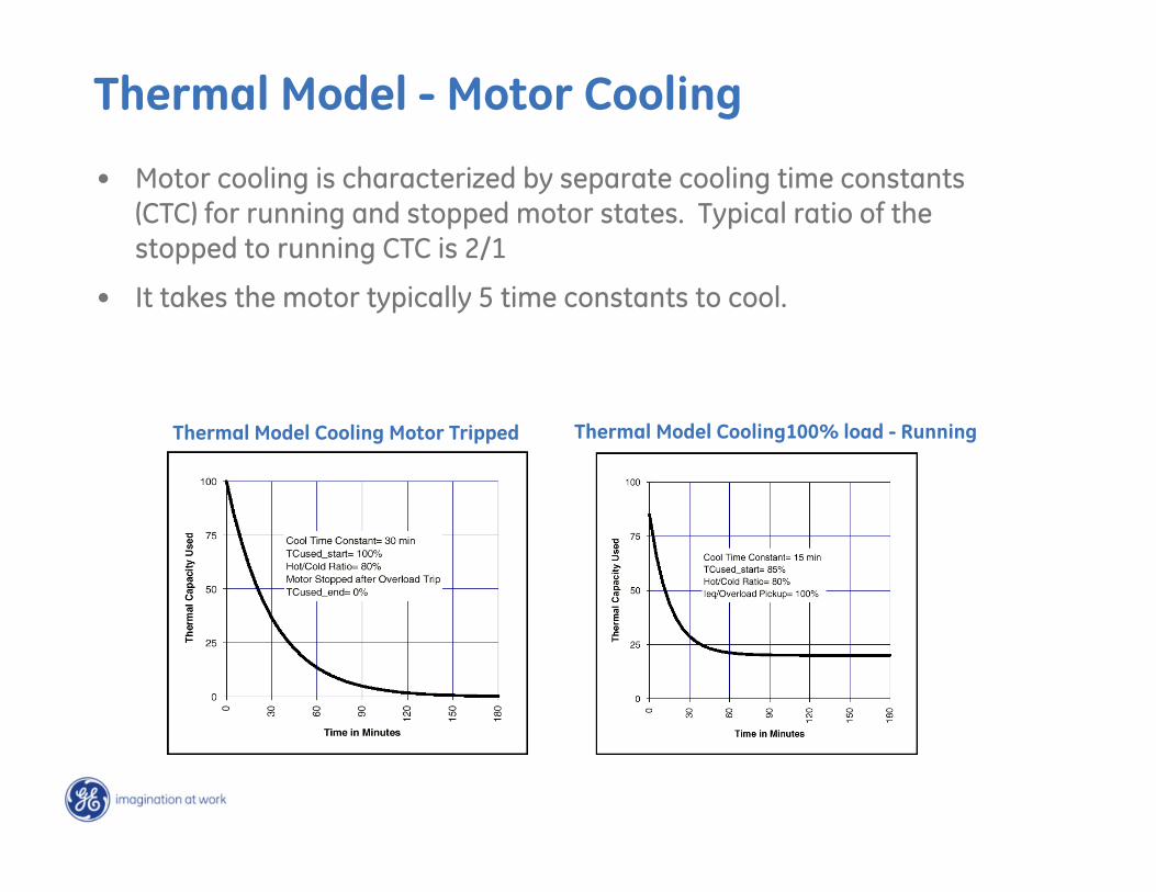
Thermal Model - Motor Cooling
• Motor cooling is characterized by separate cooling time constants (CTC) for running and stopped motor states. Typical ratio of the stopped to running CTC is 2/1
• It takes the motor typically 5 time constants to cool.
Thermal Model Cooling100% load - RunningThermal Model Cooling Motor Tripped
• The overall result of an overvoltage condition is a decrease in load current and poor power factor.
• Although old motors had robust design, new motors are designed close to saturation point for better utilization of core materials and increasing the V/Hz ratio cause saturation of air gap flux leading to motor heating.
• The overvoltage element should be set to 110% of the motors nameplate unless otherwise started in the data sheets.
Overvoltage Protection
• The overall result of an undervoltage condition is an increase in current and motor heating and a reduction in overall motor performance.
• The undervoltage protection element can be thought of as backup protection for the thermal overload element. In some cases, if an undervoltage condition exists it may be desirable to trip the motor faster than thermal overload element.
• The undervoltage trip should be set to 90% of nameplate unless otherwise stated on the motor data sheets.
• Motors that are connected to the same source/bus may experience a temporary undervoltage, when one of motors starts. To override this temporary voltage sags, a time delay setpoint should be set greater than the motor starting time.
Undervoltage Protection
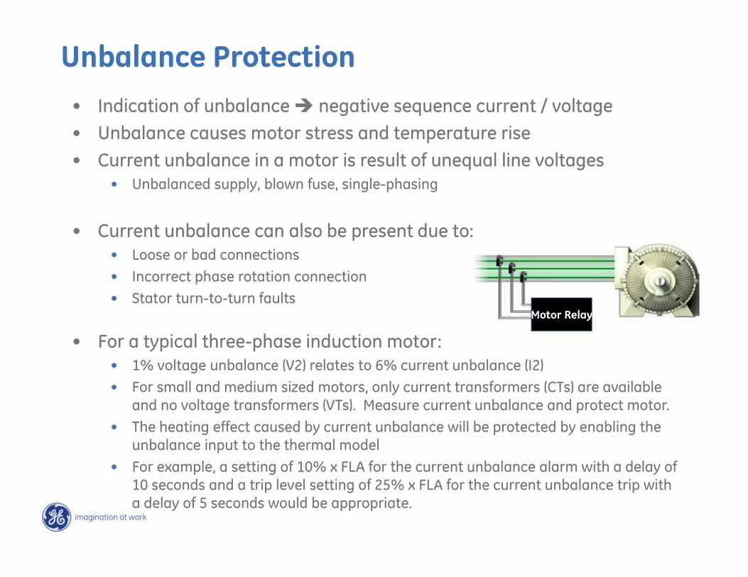
Unbalance Protection• Indication of unbalance negative sequence current / voltage• Unbalance causes motor stress and temperature rise• Current unbalance in a motor is result of unequal line voltages
• Unbalanced supply, blown fuse, single-phasing
• Current unbalance can also be present due to:• Loose or bad connections• Incorrect phase rotation connection• Stator turn-to-turn faults
• For a typical three-phase induction motor:• 1% voltage unbalance (V2) relates to 6% current unbalance (I2)• For small and medium sized motors, only current transformers (CTs) are available
and no voltage transformers (VTs). Measure current unbalance and protect motor. • The heating effect caused by current unbalance will be protected by enabling the
unbalance input to the thermal model• For example, a setting of 10% x FLA for the current unbalance alarm with a delay of
10 seconds and a trip level setting of 25% x FLA for the current unbalance trip with a delay of 5 seconds would be appropriate.
Motor Relay
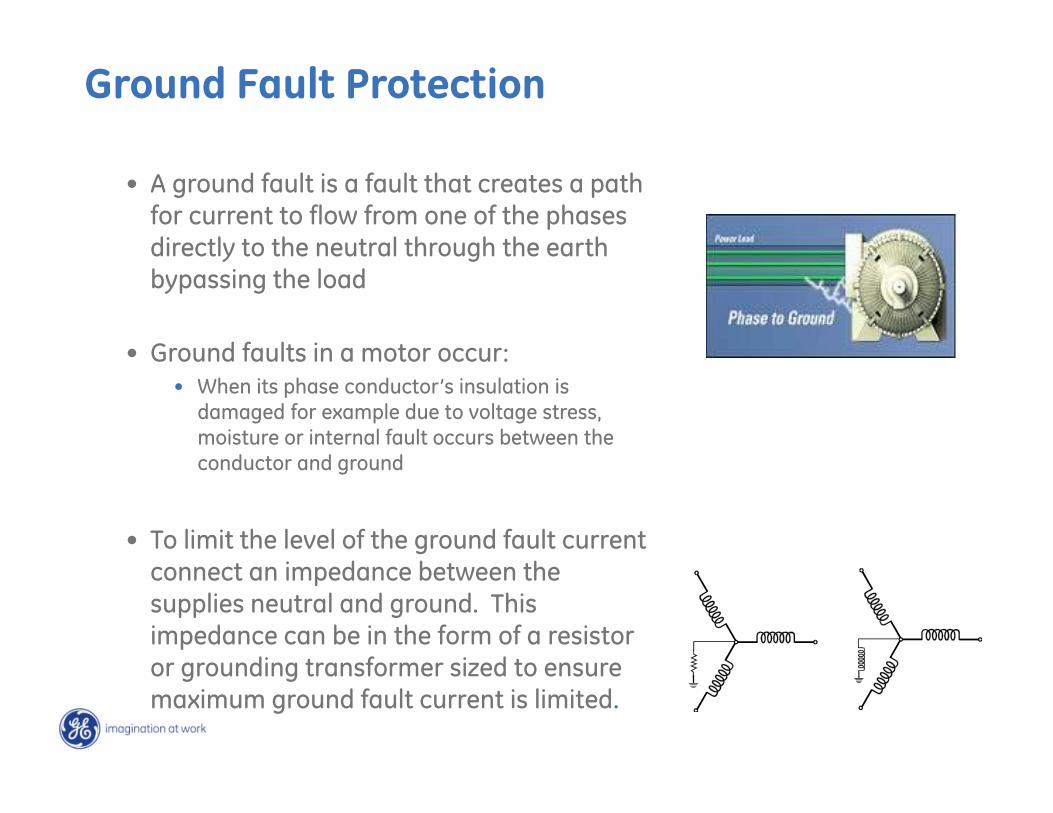
• A ground fault is a fault that creates a path for current to flow from one of the phases directly to the neutral through the earth bypassing the load
• Ground faults in a motor occur:• When its phase conductor’s insulation is
damaged for example due to voltage stress, moisture or internal fault occurs between the conductor and ground
• To limit the level of the ground fault current connect an impedance between the supplies neutral and ground. This impedance can be in the form of a resistor or grounding transformer sized to ensure maximum ground fault current is limited.
Ground Fault Protection
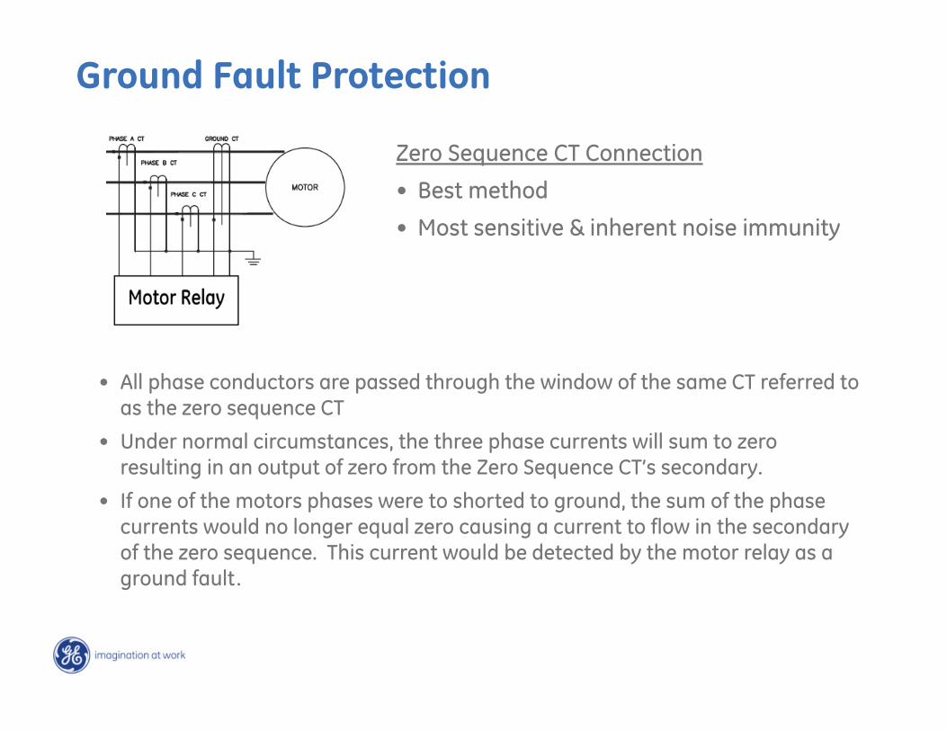
• All phase conductors are passed through the window of the same CT referred to as the zero sequence CT
• Under normal circumstances, the three phase currents will sum to zero resulting in an output of zero from the Zero Sequence CT’s secondary.
• If one of the motors phases were to shorted to ground, the sum of the phase currents would no longer equal zero causing a current to flow in the secondary of the zero sequence. This current would be detected by the motor relay as a ground fault.
Zero Sequence CT Connection
• Best method
• Most sensitive & inherent noise immunity
Ground Fault Protection
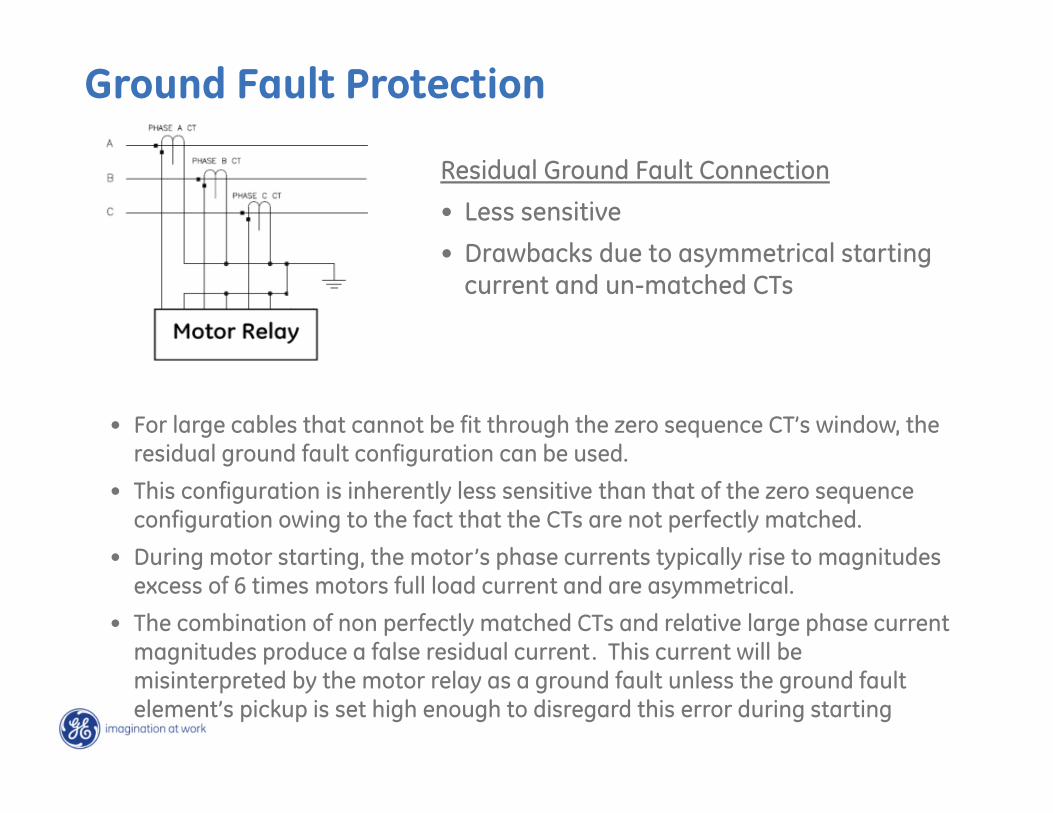
• For large cables that cannot be fit through the zero sequence CT’s window, the residual ground fault configuration can be used.
• This configuration is inherently less sensitive than that of the zero sequence configuration owing to the fact that the CTs are not perfectly matched.
• During motor starting, the motor’s phase currents typically rise to magnitudes excess of 6 times motors full load current and are asymmetrical.
• The combination of non perfectly matched CTs and relative large phase current magnitudes produce a false residual current. This current will be misinterpreted by the motor relay as a ground fault unless the ground fault element’s pickup is set high enough to disregard this error during starting
Residual Ground Fault Connection
• Less sensitive
• Drawbacks due to asymmetrical starting current and un-matched CTs
Ground Fault Protection
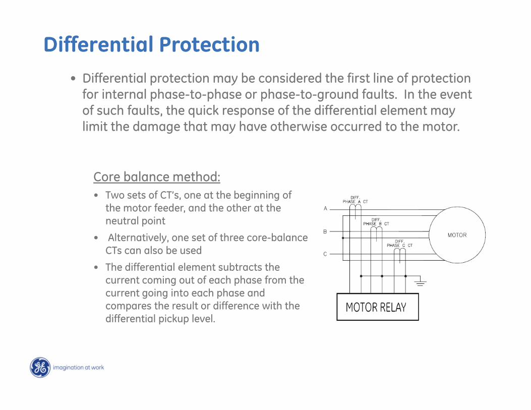
Differential Protection• Differential protection may be considered the first line of protection
for internal phase-to-phase or phase-to-ground faults. In the event of such faults, the quick response of the differential element may limit the damage that may have otherwise occurred to the motor.
Core balance method:• Two sets of CT’s, one at the beginning of
the motor feeder, and the other at the neutral point
• Alternatively, one set of three core-balance CTs can also be used
• The differential element subtracts the current coming out of each phase from the current going into each phase and compares the result or difference with the differential pickup level.
Differential Protection
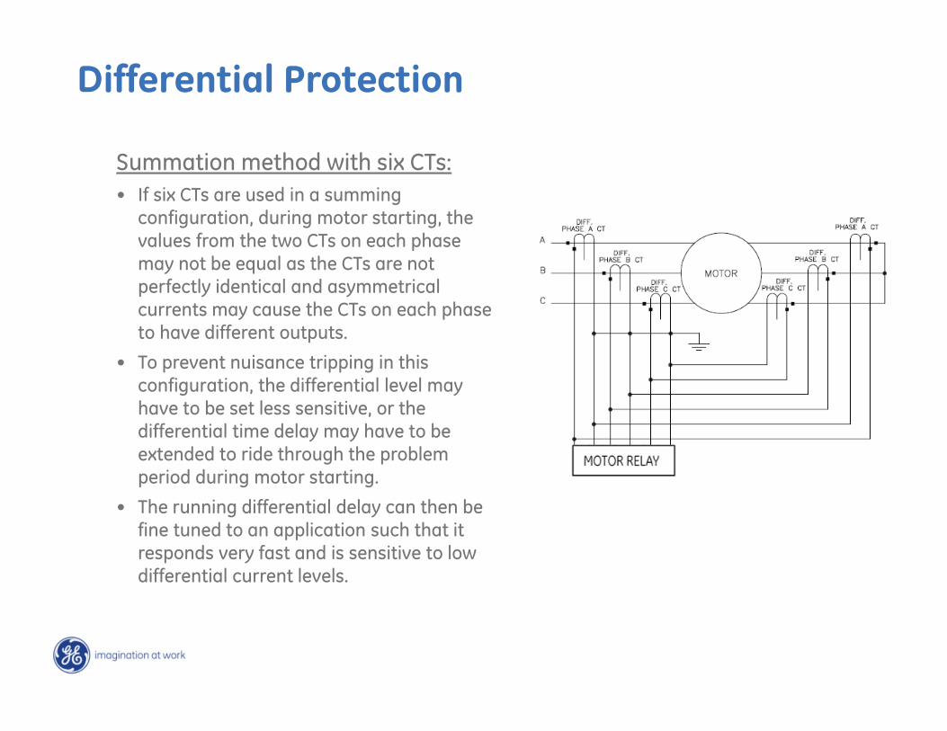
Summation method with six CTs:• If six CTs are used in a summing
configuration, during motor starting, the values from the two CTs on each phase may not be equal as the CTs are not perfectly identical and asymmetrical currents may cause the CTs on each phase to have different outputs.
• To prevent nuisance tripping in this configuration, the differential level may have to be set less sensitive, or the differential time delay may have to be extended to ride through the problem period during motor starting.
• The running differential delay can then be fine tuned to an application such that it responds very fast and is sensitive to low differential current levels.
Differential Protection
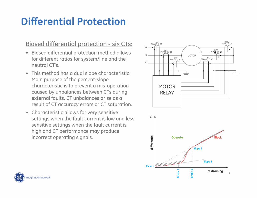
Biased differential protection - six CTs:• Biased differential protection method allows
for different ratios for system/line and the neutral CT’s.
• This method has a dual slope characteristic. Main purpose of the percent-slope characteristic is to prevent a mis-operation caused by unbalances between CTs during external faults. CT unbalances arise as a result of CT accuracy errors or CT saturation.
• Characteristic allows for very sensitive settings when the fault current is low and less sensitive settings when the fault current is high and CT performance may produce incorrect operating signals.
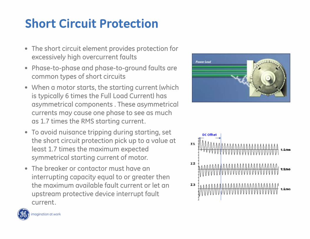
• The short circuit element provides protection for excessively high overcurrent faults
• Phase-to-phase and phase-to-ground faults are common types of short circuits
• When a motor starts, the starting current (which is typically 6 times the Full Load Current) has asymmetrical components . These asymmetrical currents may cause one phase to see as much as 1.7 times the RMS starting current.
• To avoid nuisance tripping during starting, set the short circuit protection pick up to a value at least 1.7 times the maximum expected symmetrical starting current of motor.
• The breaker or contactor must have an interrupting capacity equal to or greater then the maximum available fault current or let an upstream protective device interrupt fault current.
Short Circuit Protection
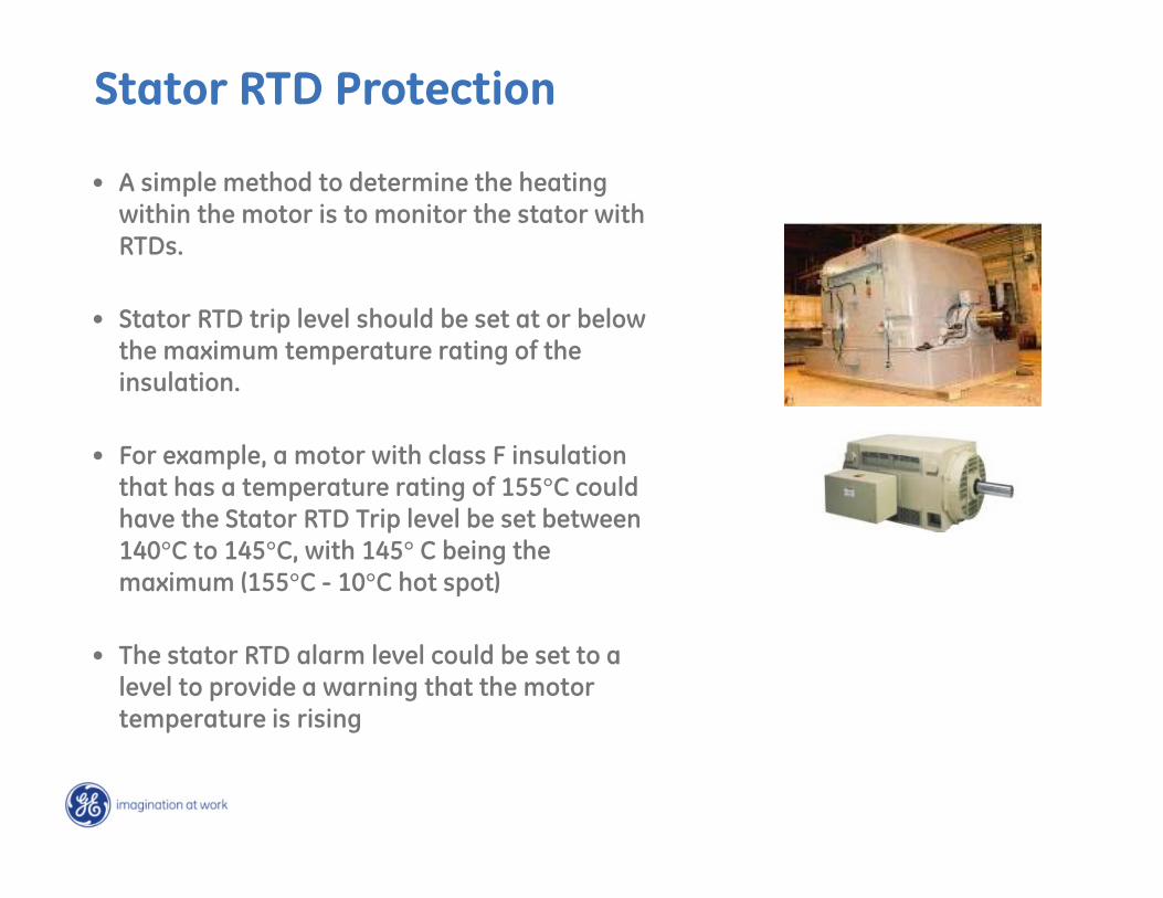
• A simple method to determine the heating within the motor is to monitor the stator with RTDs.
• Stator RTD trip level should be set at or below the maximum temperature rating of the insulation.
• For example, a motor with class F insulation that has a temperature rating of 155°C could have the Stator RTD Trip level be set between 140°C to 145°C, with 145° C being the maximum (155°C - 10°C hot spot)
• The stator RTD alarm level could be set to a level to provide a warning that the motor temperature is rising
Stator RTD Protection
Broken Rotor Bar (BRB) Detection
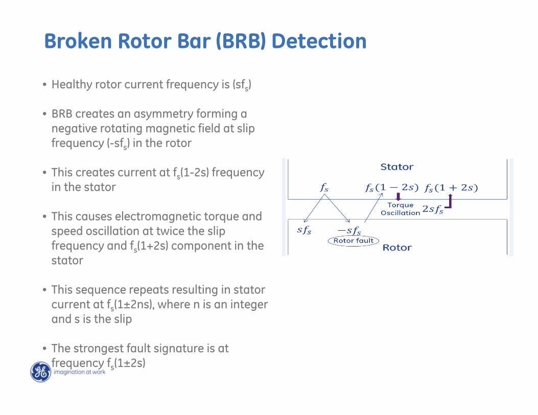
• Healthy rotor current frequency is (sfs)
• BRB creates an asymmetry forming a negative rotating magnetic field at slip frequency (-sfs) in the rotor
• This creates current at fs(1-2s) frequency in the stator
• This causes electromagnetic torque and speed oscillation at twice the slip frequency and fs(1+2s) component in the stator
• This sequence repeats resulting in stator current at fs(1±2ns), where n is an integer and s is the slip
• The strongest fault signature is at frequency fs(1±2s)
Broken Rotor Bar Detection
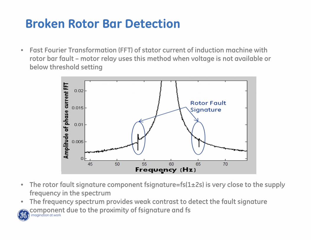
• The rotor fault signature component fsignature=fs(1±2s) is very close to the supply frequency in the spectrum
• The frequency spectrum provides weak contrast to detect the fault signature component due to the proximity of fsignature and fs
• Fast Fourier Transformation (FFT) of stator current of induction machine with rotor bar fault – motor relay uses this method when voltage is not available or below threshold setting
Power Based Broken Rotor Bar Detection
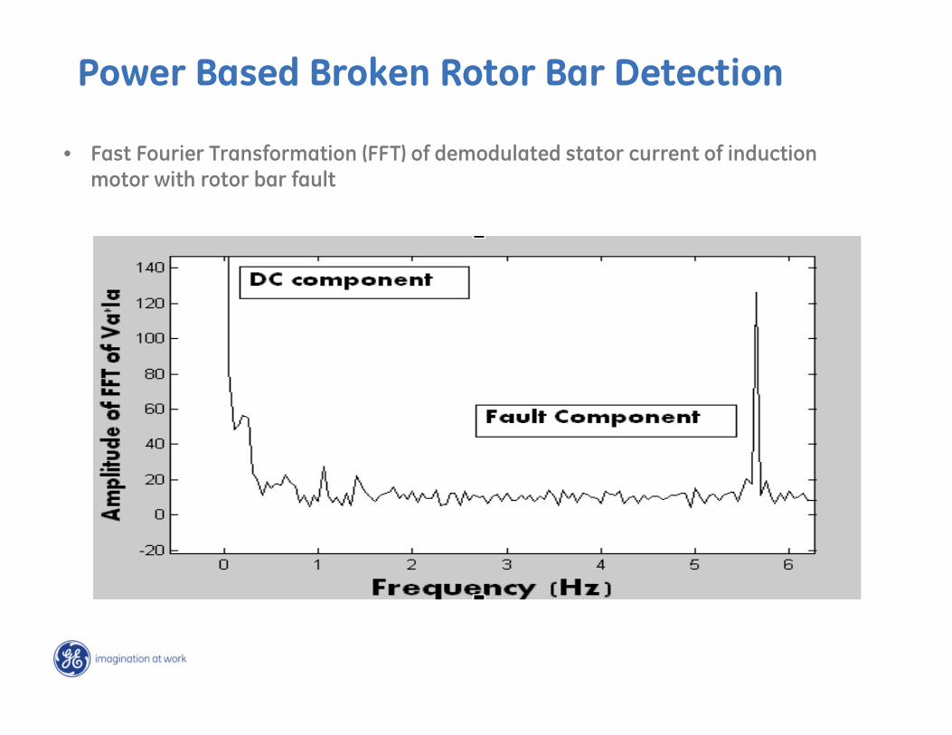
• Fast Fourier Transformation (FFT) of demodulated stator current of induction motor with rotor bar fault
Broken Rotor Bar Detection
Additional Protection Methods
• Start InhibitThis function will limit starts when the motor is already hot.
• Starts/Hour
• Time Between Starts (Jogging)
• Bearing RTD Protection
• Acceleration TripSet higher than the maximum starting time to avoid nuisance tripping when the voltage is lower or for varying loads during acceleration.
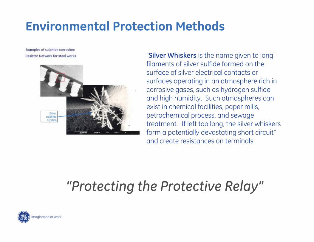
“Silver Whiskers is the name given to long filaments of silver sulfide formed on the surface of silver electrical contacts or surfaces operating in an atmosphere rich in corrosive gases, such as hydrogen sulfide and high humidity. Such atmospheres can exist in chemical facilities, paper mills, petrochemical process, and sewage treatment. If left too long, the silver whiskers form a potentially devastating short circuit” and create resistances on terminals
Environmental Protection Methods
“Protecting the Protective Relay”
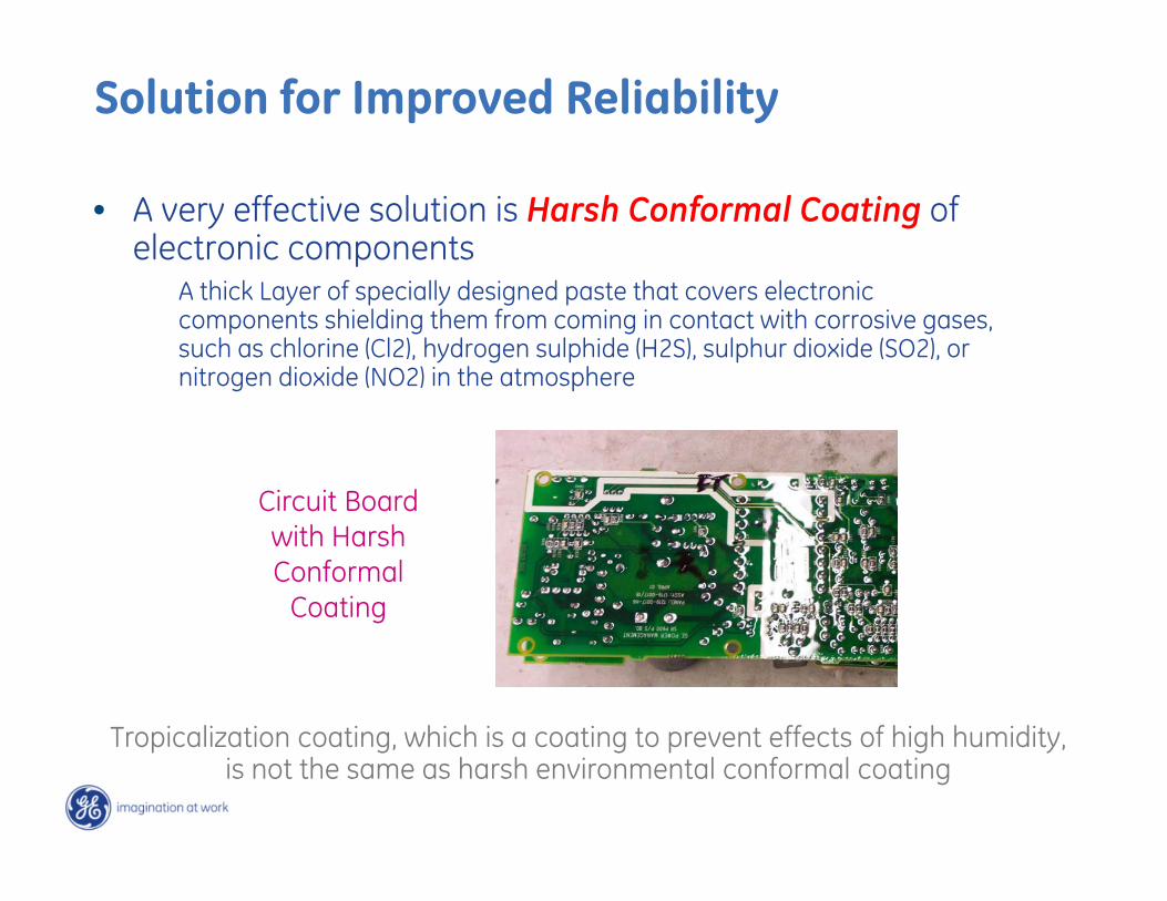
• A very effective solution is Harsh Conformal Coating of electronic components
A thick Layer of specially designed paste that covers electronic components shielding them from coming in contact with corrosive gases, such as chlorine (Cl2), hydrogen sulphide (H2S), sulphur dioxide (SO2), or nitrogen dioxide (NO2) in the atmosphere
Tropicalization coating, which is a coating to prevent effects of high humidity, is not the same as harsh environmental conformal coating
Circuit Board with Harsh Conformal
Coating
Solution for Improved Reliability

Motor Thermal Lockout:
Why Can’t I Start My Motor?
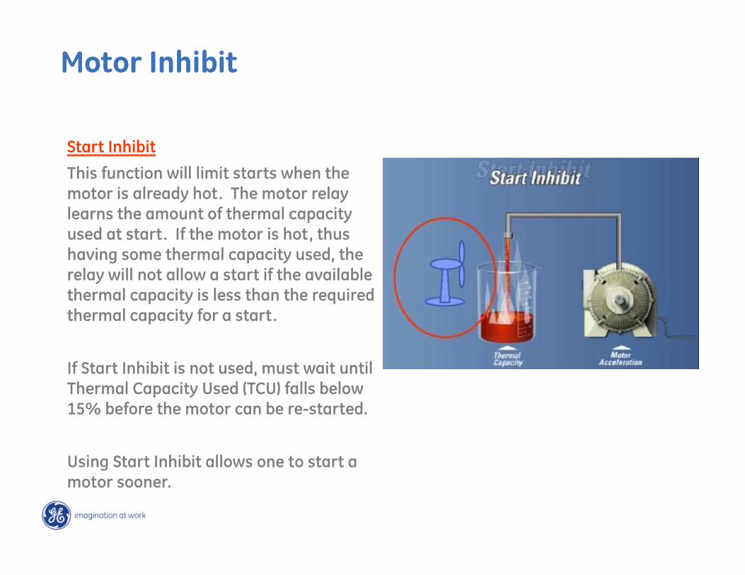
Start Inhibit
This function will limit starts when the motor is already hot. The motor relay learns the amount of thermal capacity used at start. If the motor is hot, thus having some thermal capacity used, the relay will not allow a start if the available thermal capacity is less than the required thermal capacity for a start.
If Start Inhibit is not used, must wait until Thermal Capacity Used (TCU) falls below 15% before the motor can be re-started.
Using Start Inhibit allows one to start a motor sooner.
Motor Inhibit
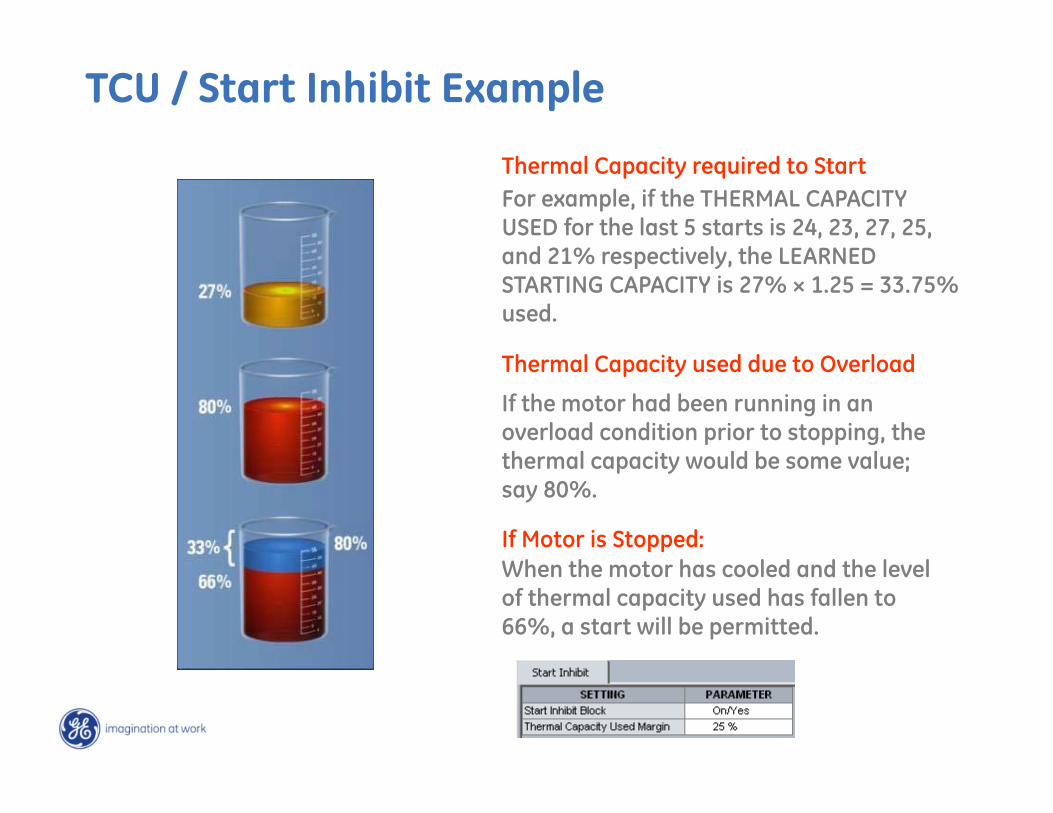
Thermal Capacity required to Start
Thermal Capacity used due to Overload
When the motor has cooled and the level of thermal capacity used has fallen to 66%, a start will be permitted.
If the motor had been running in an overload condition prior to stopping, the thermal capacity would be some value; say 80%.
For example, if the THERMAL CAPACITY USED for the last 5 starts is 24, 23, 27, 25, and 21% respectively, the LEARNED STARTING CAPACITY is 27% × 1.25 = 33.75% used.
If Motor is Stopped:
TCU / Start Inhibit Example
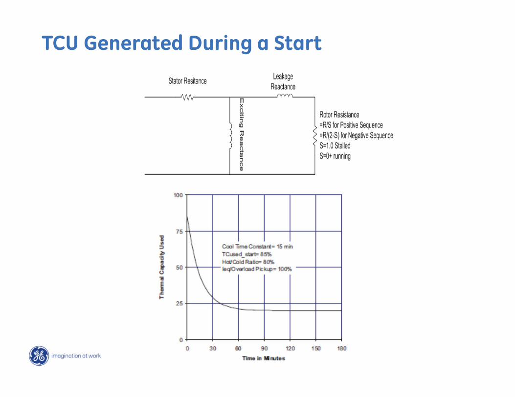
TCU Generated During a Start
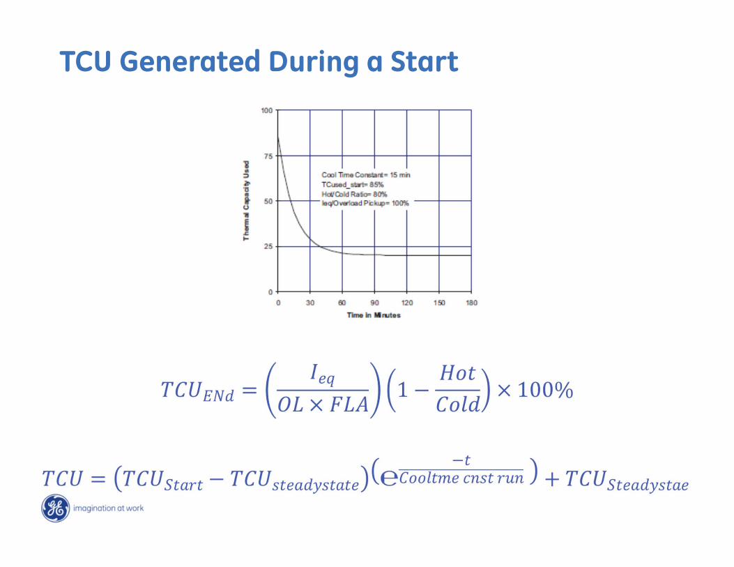
TCU Generated During a Start

Case Study:
Start Inhibit Set Too High
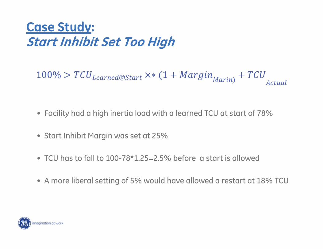
• Facility had a high inertia load with a learned TCU at start of 78%
• Start Inhibit Margin was set at 25%
• TCU has to fall to 100-78*1.25=2.5% before a start is allowed
• A more liberal setting of 5% would have allowed a restart at 18% TCU
Case Study:Start Inhibit Set Too High
• Start Inhibit needs to match the application
• With high inertia motor applications, enabling the start inhibit feature is not helpful
• If the motor start TCU is a reasonable level (such as less than 60%), it is always recommend to enable the start inhibit function with reasonable TCU used margin setting to prevent unnecessary start inhibit blocks
Case Study:Start Inhibit Set Too High – Lessons Learned

Case Study:
Cooling Time Constant Set as Cooling Time
• Facility found cooling times of 60 minutes (running) and 125 minutes (stop)….
• And set these times as cooling time constants in the motor relay
• This lay dormant for several years…….
• Until a trip occurred
Case Study:Cooling Time Constants Set as Cooling Times
Case Study:Cooling Time Constants Set as Cooling Times
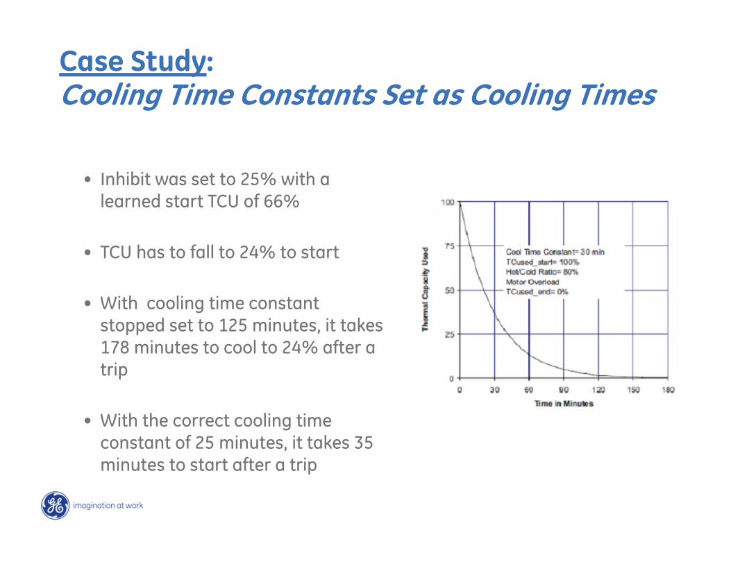
• Inhibit was set to 25% with a learned start TCU of 66%
• TCU has to fall to 24% to start
• With cooling time constant stopped set to 125 minutes, it takes 178 minutes to cool to 24% after a trip
• With the correct cooling time constant of 25 minutes, it takes 35 minutes to start after a trip
Case Study:
Hot/Cold Ratio Set Incorrectly
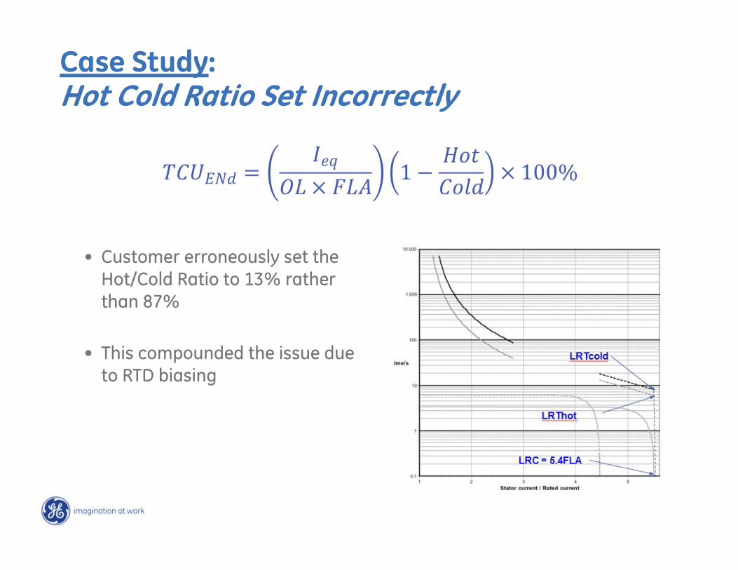
Case Study:Hot Cold Ratio Set Incorrectly
• Customer erroneously set the Hot/Cold Ratio to 13% rather than 87%
• This compounded the issue due to RTD biasing
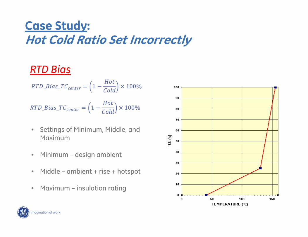
• Settings of Minimum, Middle, and Maximum
• Minimum – design ambient
• Middle – ambient + rise + hotspot
• Maximum – insulation rating
Case Study:Hot Cold Ratio Set Incorrectly
RTD Bias
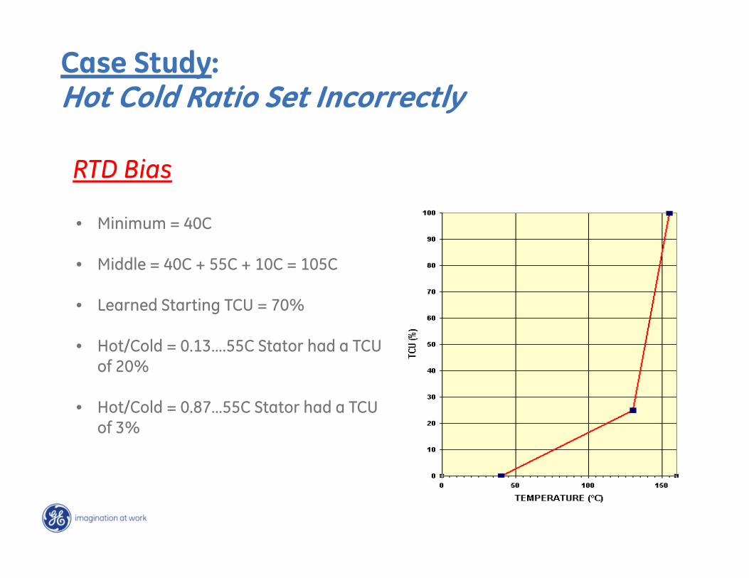
Case Study:Hot Cold Ratio Set Incorrectly
RTD Bias
• Minimum = 40C
• Middle = 40C + 55C + 10C = 105C
• Learned Starting TCU = 70%
• Hot/Cold = 0.13….55C Stator had a TCU of 20%
• Hot/Cold = 0.87…55C Stator had a TCU of 3%
Case Study:
Restart of a High Inertia Load
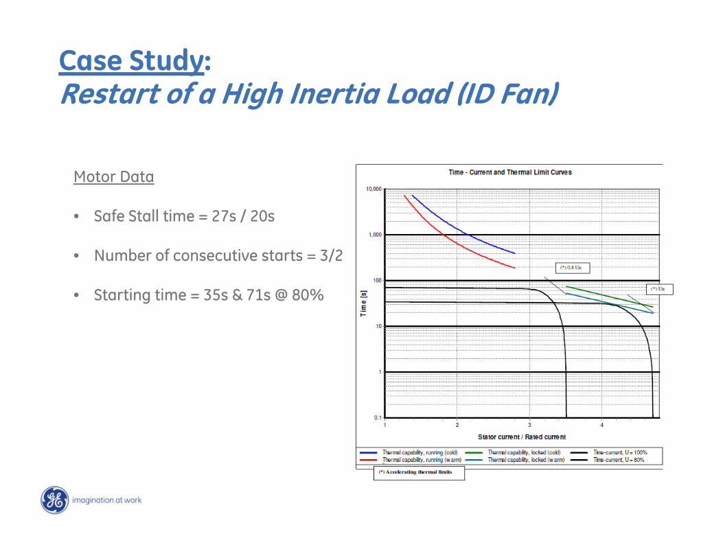
Case Study:Restart of a High Inertia Load (ID Fan)
Motor Data
• Safe Stall time = 27s / 20s
• Number of consecutive starts = 3/2
• Starting time = 35s & 71s @ 80%
Case Study:Restart of High Inertia Load – Lessons Learned
• Immediate Restart may not be available
• Voltage Dependent curves help with starting, but not restart
• Soft starting methods can help the situation
• It is necessary to obtain accurate information about the motor before designing the motor relay set points
• In some cases, it is necessary to consult the motor manufacturer when it comes to the selection of the overload curves in an application where the motor starting curves and thermal damage curves are very close to one other

Case Study:
Other Blocking Elements
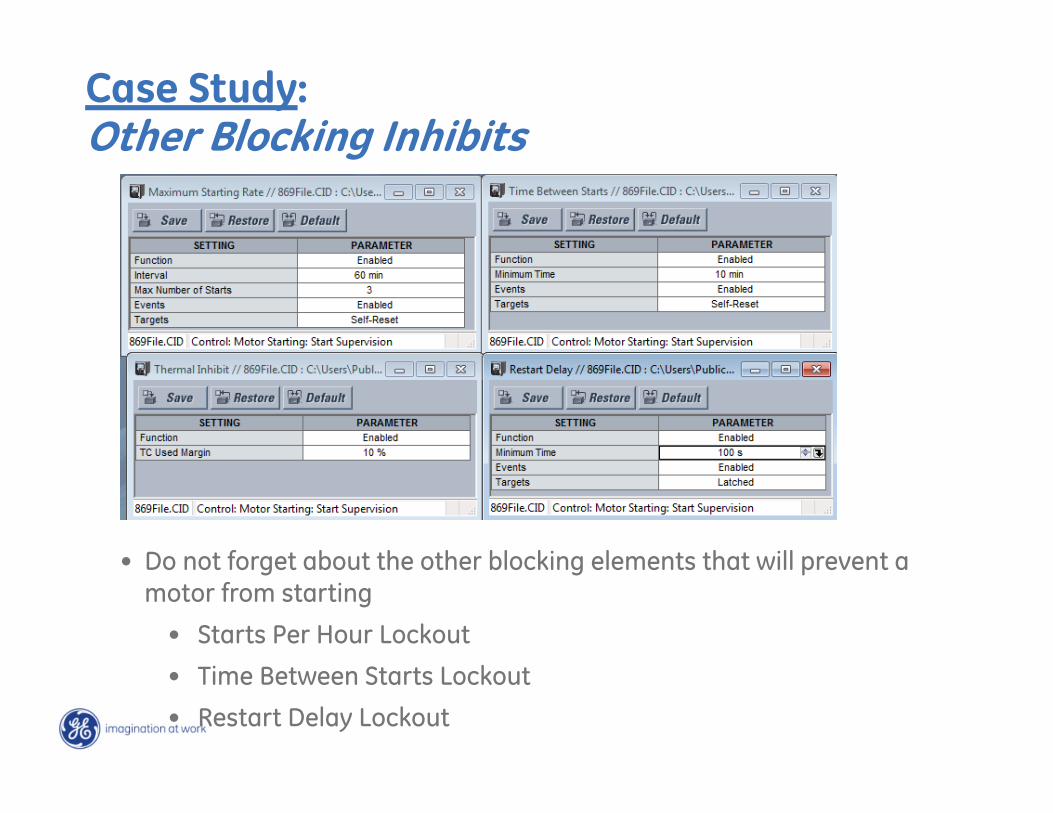
Case Study:Other Blocking Inhibits
• Do not forget about the other blocking elements that will prevent a motor from starting
• Starts Per Hour Lockout
• Time Between Starts Lockout
• Restart Delay Lockout
If I have a motor relay with a thermal model, are other inhibits really necessary?
Yes
Final Thoughts on Motor LockoutOther Blocking Inhibits
• The inhibit margins, if set too high can prevent a timely restart of the motor
• Cooling time and cooling time constants are not the same thing. You must know what value the motor relay is expecting, usually cooling time constant
• The ratio of the hot to cold safe stall time affects the motor steady state thermal capacity used, which can affect the motor thermal model and inhibit restart
• High inertia loads use large quantities of thermal capacity used during a start. This requires significant cooling times in the event of a trip.
• Starts per hour, restart rate, and time between starts may be redundant, but is probably necessary from a warranty standpoint

SR to 8 Series Retrofit

Modern Industrial Communications

Architectures
Parallel Redundancy Protocol (PRP)
IEEE 1588 Precision Time Protocol (PTP)
Ethernet Network Communications

ArchitecturesEthernet Network Communications
Historic Perspective:Trend along the history of protective relaying -continuous addition of features with the purpose of:
Increased protection reliability; Faster protection; More selective protection.
This trend triggered a continuous evolution of the communications infrastructure
First: point-to-point communications between transmission line terminals;
Later: system wide networks with fixed architectures and manually configured paths;
More recently: the Ethernet Use of the TCP/IP stack, based on the OSI model
Ethernet Network Communications Architectures
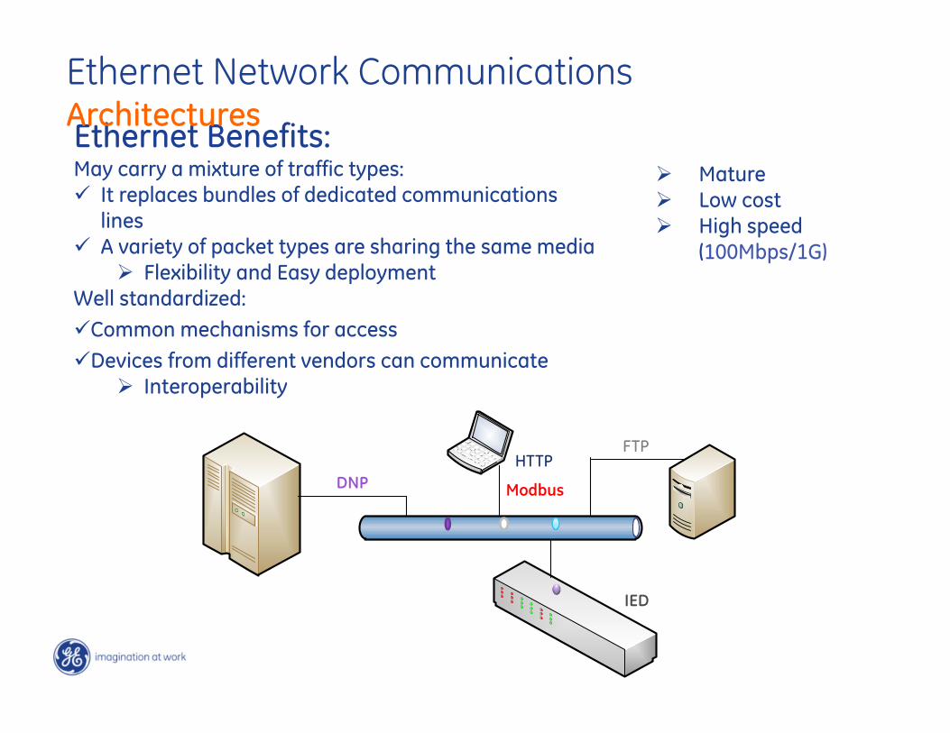
Ethernet Benefits:May carry a mixture of traffic types: It replaces bundles of dedicated communications
lines A variety of packet types are sharing the same media
Flexibility and Easy deploymentWell standardized:Common mechanisms for accessDevices from different vendors can communicate
Interoperability
ModbusDNP
FTPHTTP
IED
Mature Low cost High speed
(100Mbps/1G)
Ethernet Network Communications Architectures

A switch is a common connection point for devices in a network Used to connect segments of a Local Area Network (LAN) Contains multiple ports When a packet arrives at one port, it is copied only to the ports
that need to transmit that packet Switches operate at the Data Link Layer (layer 2) of the OSI
Reference Model LANs that use switches to join segments are called switched
LANs or, in the case of Ethernet networks, switched Ethernet LANs
Ethernet Devices - Switches
Ethernet Network Communications Architectures
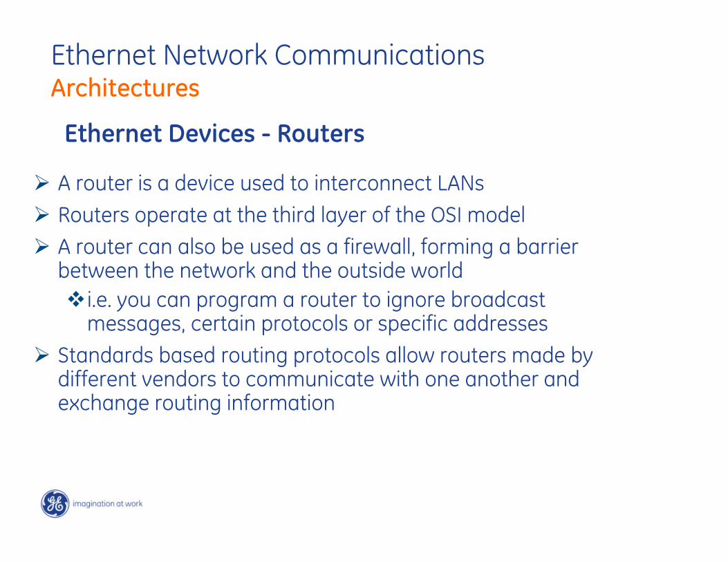
A router is a device used to interconnect LANs Routers operate at the third layer of the OSI model A router can also be used as a firewall, forming a barrier
between the network and the outside worldi.e. you can program a router to ignore broadcast
messages, certain protocols or specific addresses Standards based routing protocols allow routers made by
different vendors to communicate with one another and exchange routing information
Ethernet Devices - Routers
Ethernet Network Communications Architectures
Parallel Redundancy Protocol (PRP)
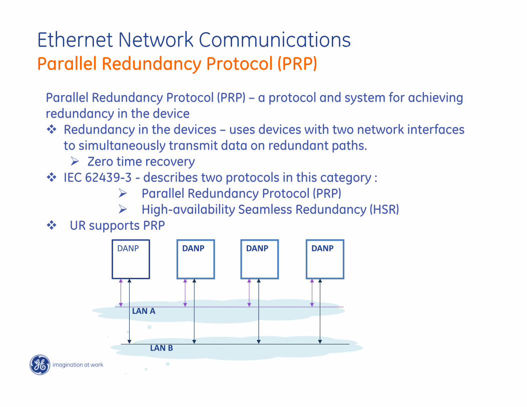
Parallel Redundancy Protocol (PRP) – a protocol and system for achieving redundancy in the device Redundancy in the devices – uses devices with two network interfaces
to simultaneously transmit data on redundant paths. Zero time recovery
IEC 62439-3 - describes two protocols in this category : Parallel Redundancy Protocol (PRP) High-availability Seamless Redundancy (HSR)
UR supports PRP
LAN B
DANP DANP DANP DANP
LAN A
Ethernet Network Communications Parallel Redundancy Protocol (PRP)
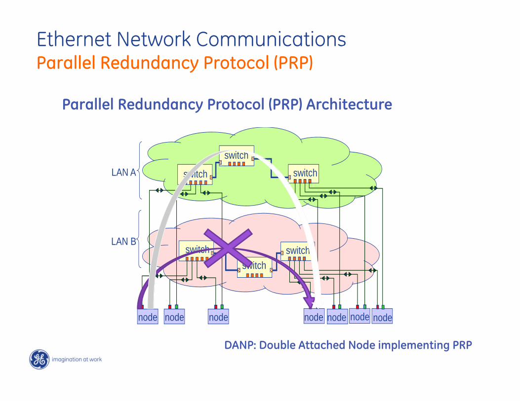
Parallel Redundancy Protocol (PRP) Architecture
node node node node node node node
switch
switch
switchswitch
switch
switchLAN A
LAN B
DANP: Double Attached Node implementing PRP
Ethernet Network Communications Parallel Redundancy Protocol (PRP)
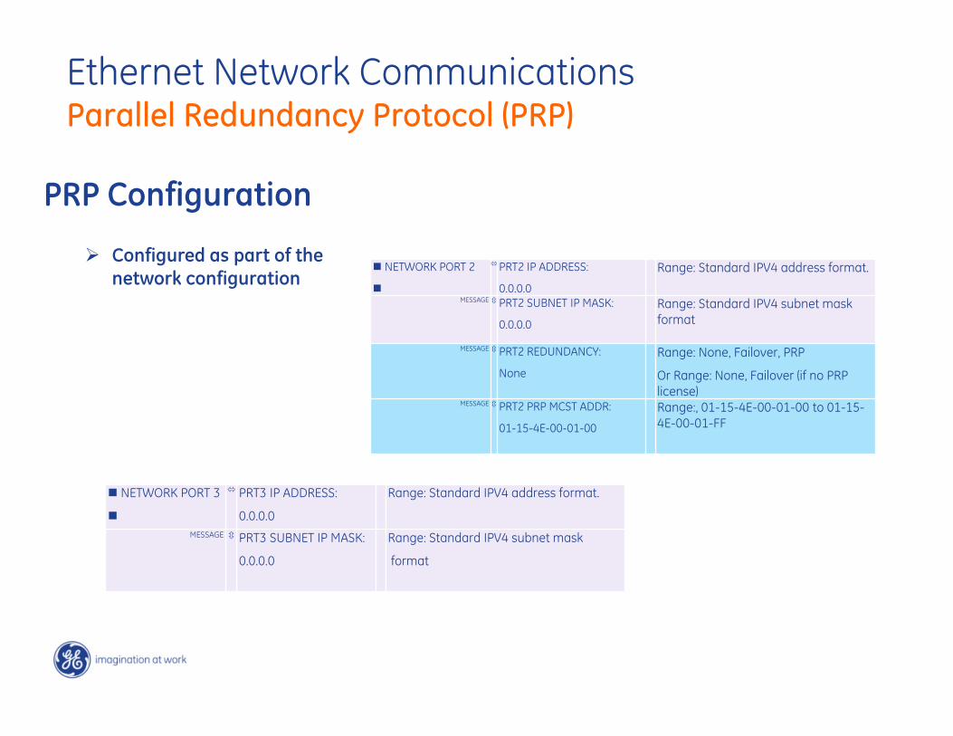
PRP Configuration
NETWORK PORT 2
PRT2 IP ADDRESS:
0.0.0.0
Range: Standard IPV4 address format.
MESSAGE PRT2 SUBNET IP MASK:
0.0.0.0
Range: Standard IPV4 subnet mask format
MESSAGE PRT2 REDUNDANCY:
None
Range: None, Failover, PRP
Or Range: None, Failover (if no PRP license)
MESSAGE PRT2 PRP MCST ADDR:
01-15-4E-00-01-00
Range:, 01-15-4E-00-01-00 to 01-15-4E-00-01-FF
NETWORK PORT 3
PRT3 IP ADDRESS:
0.0.0.0
Range: Standard IPV4 address format.
MESSAGE PRT3 SUBNET IP MASK:
0.0.0.0
Range: Standard IPV4 subnet mask
format
Configured as part of the network configuration
Ethernet Network Communications Parallel Redundancy Protocol (PRP)

Precision Time Protocol (PTP)
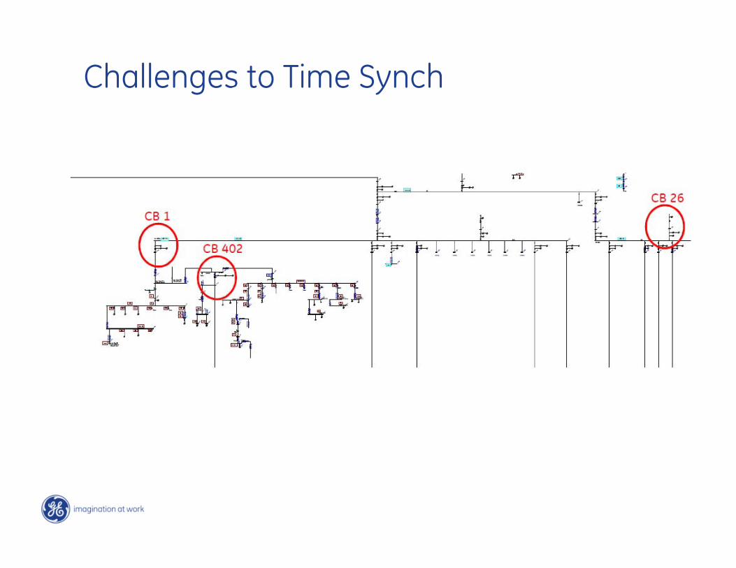
Challenges to Time Synch
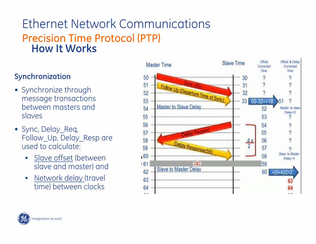
How It Works
Synchronization
• Synchronize through message transactions between masters and slaves
• Sync, Delay_Req, Follow_Up, Delay_Resp are used to calculate: • Slave offset (between
slave and master) and• Network delay (travel
time) between clocks
Ethernet Network Communications Precision Time Protocol (PTP)
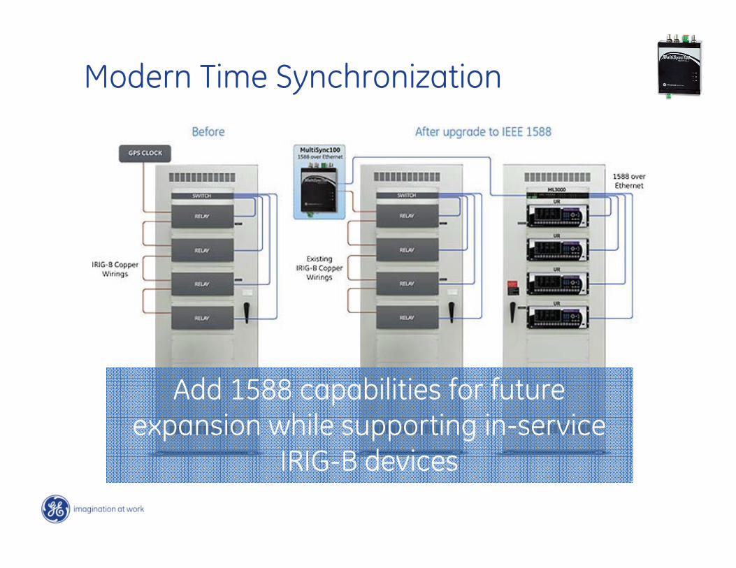
Modern Time Synchronization
Add 1588 capabilities for future expansion while supporting in-service
IRIG-B devices
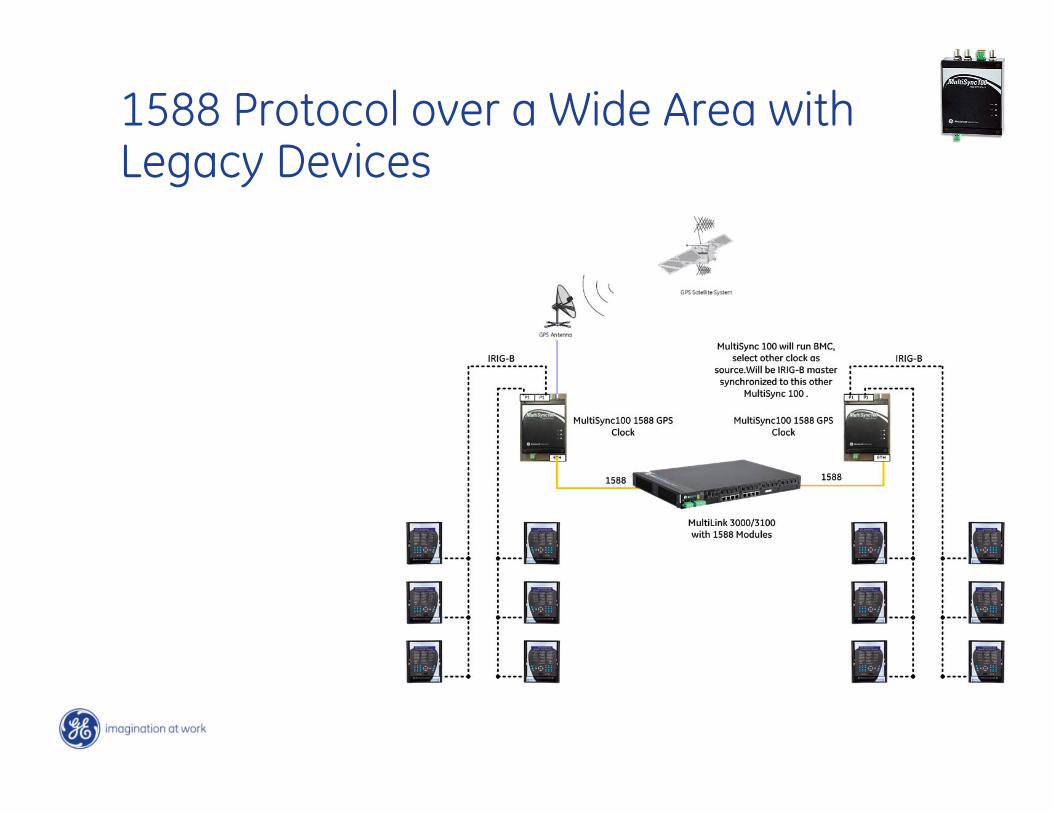
1588 Protocol over a Wide Area with Legacy Devices

What we’ll cover
• GE Digital Energy Multilin Motor Protective Relay Offerings
• AC Motor Protection Fundamentals
• Motor Thermal Lockout – Case Studies
82

83
Eliminate the Arc Flash Hazard
8484
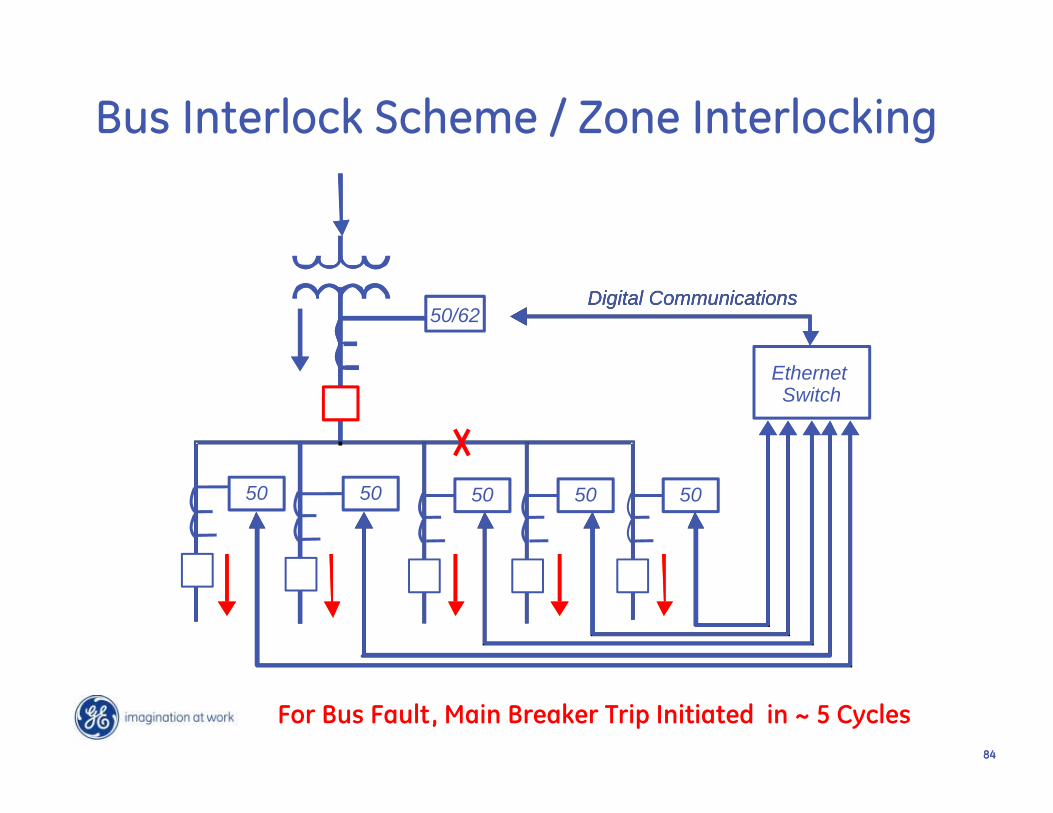
50/62
EthernetSwitch
Digital CommunicationsDigital Communications
5050 50 50 50
Bus Interlock Scheme / Zone Interlocking
For Bus Fault, Main Breaker Trip Initiated in ~ 5 Cycles
8585
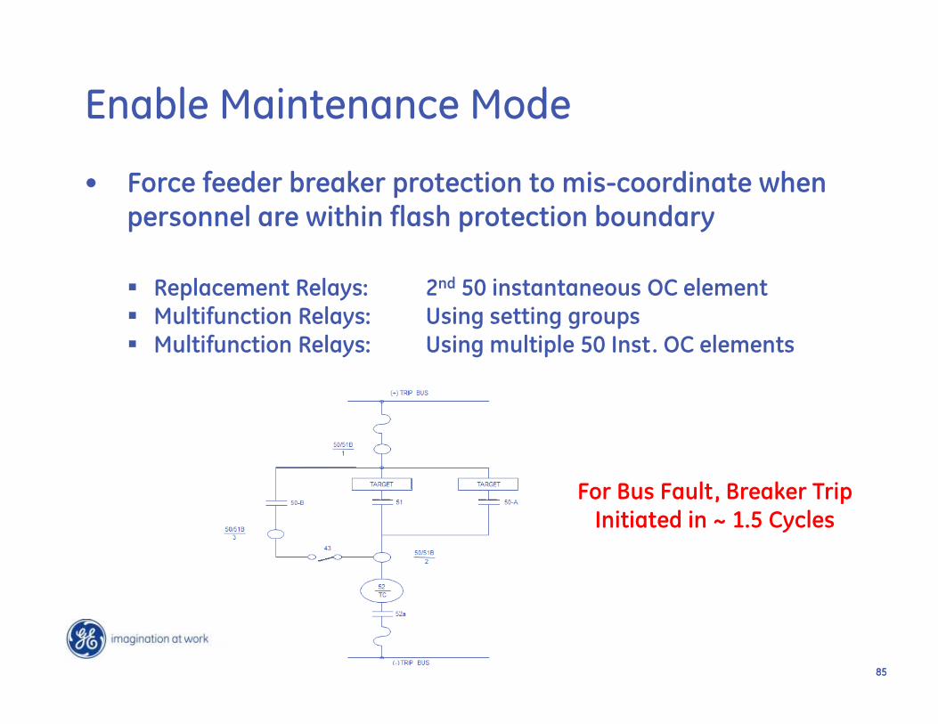
• Force feeder breaker protection to mis-coordinate when personnel are within flash protection boundary
Replacement Relays: 2nd 50 instantaneous OC element Multifunction Relays: Using setting groups Multifunction Relays: Using multiple 50 Inst. OC elements
Enable Maintenance Mode
For Bus Fault, Breaker Trip Initiated in ~ 1.5 Cycles
8686
87
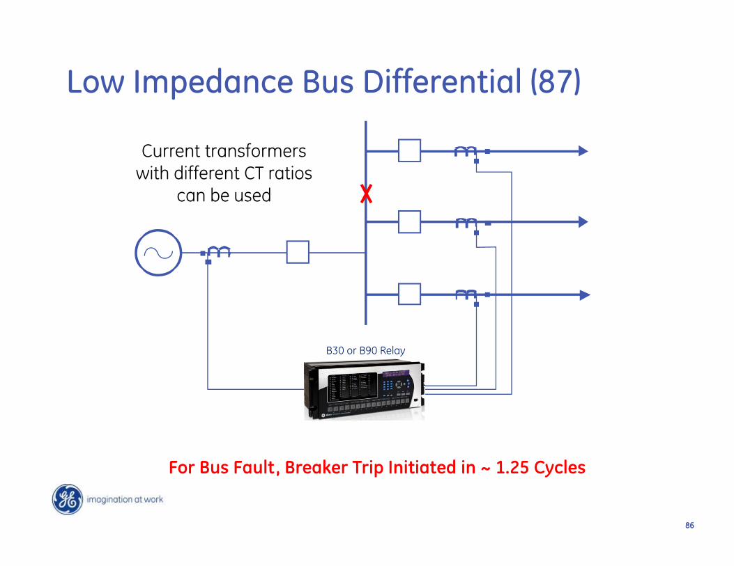
Low Impedance Bus Differential (87)
For Bus Fault, Breaker Trip Initiated in ~ 1.25 Cycles
B30 or B90 Relay
Current transformers with different CT ratios
can be used
8787
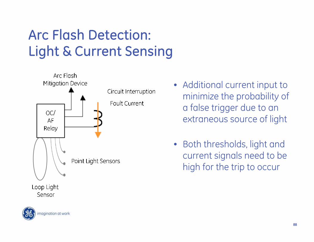
Arc Flash Detection with Light Sensing
Limitations of light only sensing:
• Fiber loops could be damaged due to bending or pinching• Difficult to re-route the damaged fiber loop• Arc flash device may malfunction if light sensing threshold
is not high enough• No additional security
8888
• Additional current input to minimize the probability of a false trigger due to an extraneous source of light
• Both thresholds, light and current signals need to be high for the trip to occur
Arc Flash Detection: Light & Current Sensing
8989
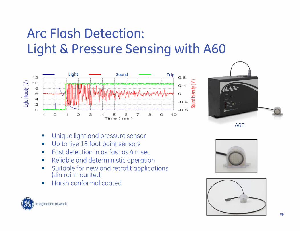
Unique light and pressure sensor Up to five 18 foot point sensors Fast detection in as fast as 4 msec Reliable and deterministic operation Suitable for new and retrofit applications
(din rail mounted) Harsh conformal coated
Arc Flash Detection: Light & Pressure Sensing with A60
A60
9090
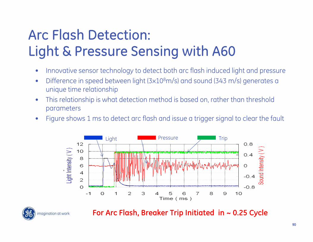
• Innovative sensor technology to detect both arc flash induced light and pressure• Difference in speed between light (3x10⁸m/s) and sound (343 m/s) generates a
unique time relationship• This relationship is what detection method is based on, rather than threshold
parameters• Figure shows 1 ms to detect arc flash and issue a trigger signal to clear the fault
PressureLight Trip
Arc Flash Detection: Light & Pressure Sensing with A60
For Arc Flash, Breaker Trip Initiated in ~ 0.25 Cycle
9191
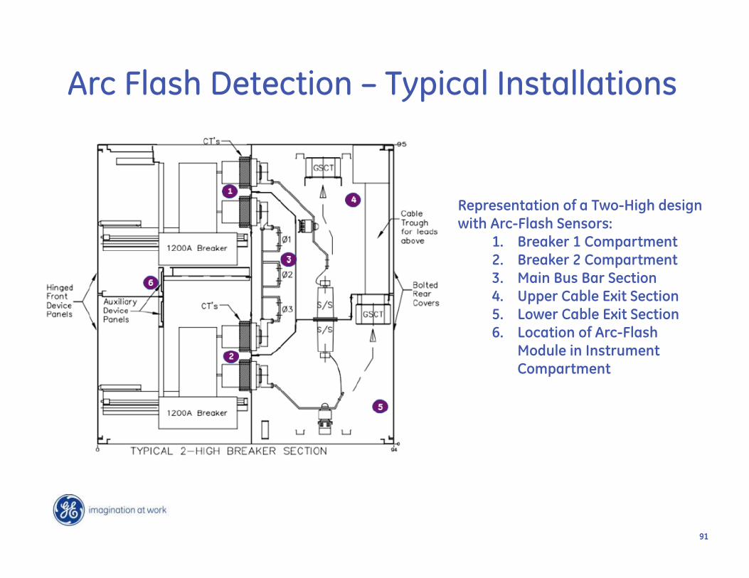
Representation of a Two-High design with Arc-Flash Sensors:
1. Breaker 1 Compartment2. Breaker 2 Compartment3. Main Bus Bar Section4. Upper Cable Exit Section5. Lower Cable Exit Section6. Location of Arc-Flash
Module in Instrument Compartment
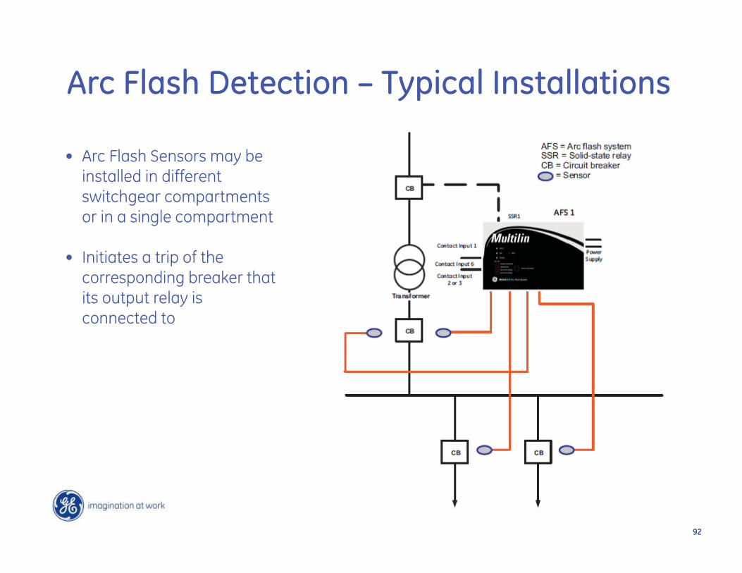
Arc Flash Detection – Typical Installations
9292
• Arc Flash Sensors may be installed in different switchgear compartments or in a single compartment
• Initiates a trip of the corresponding breaker that its output relay is connected to
Arc Flash Detection – Typical Installations
9393
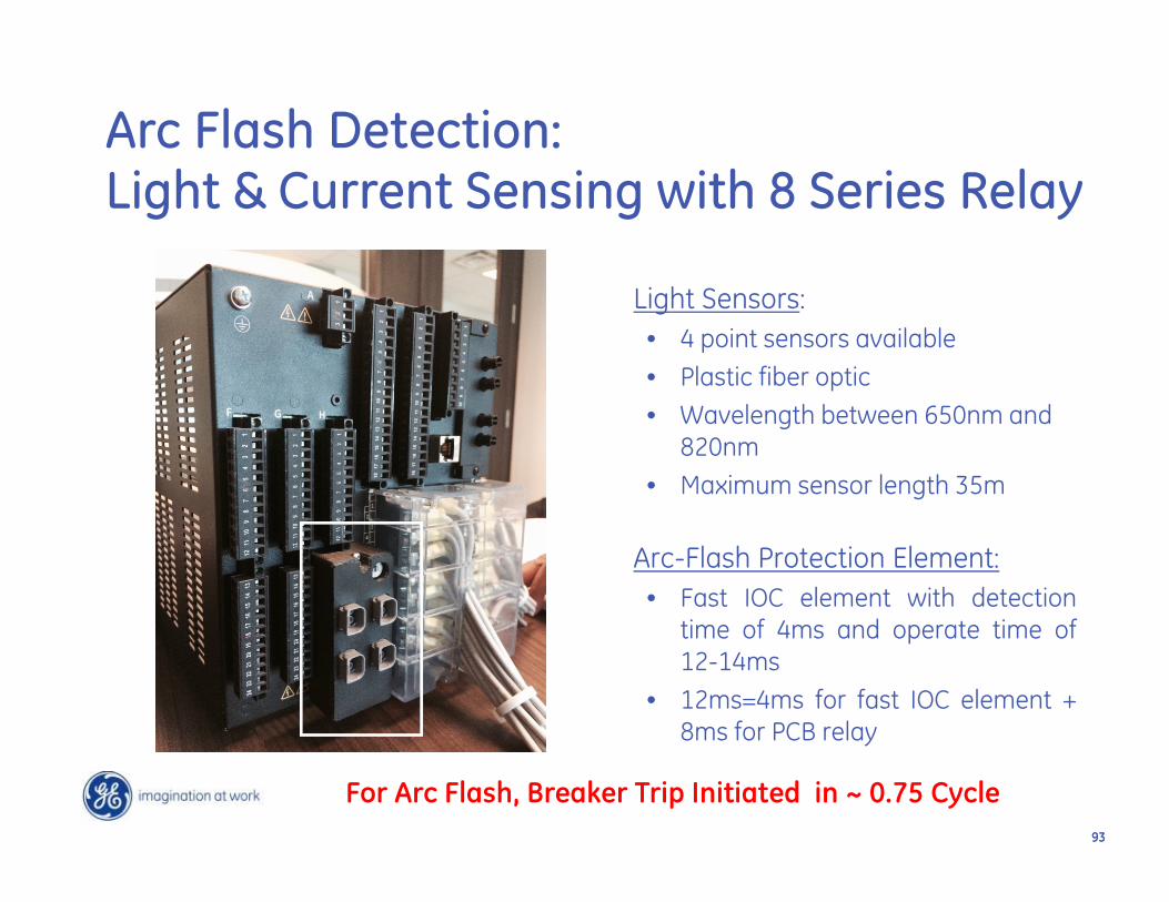
Light Sensors:• 4 point sensors available• Plastic fiber optic• Wavelength between 650nm and
820nm• Maximum sensor length 35m
Arc-Flash Protection Element:• Fast IOC element with detection
time of 4ms and operate time of12-14ms
• 12ms=4ms for fast IOC element +8ms for PCB relay
Arc Flash Detection: Light & Current Sensing with 8 Series Relay
For Arc Flash, Breaker Trip Initiated in ~ 0.75 Cycle
Page 94GE Digital Energy
www.GEDigitalEnergy.com
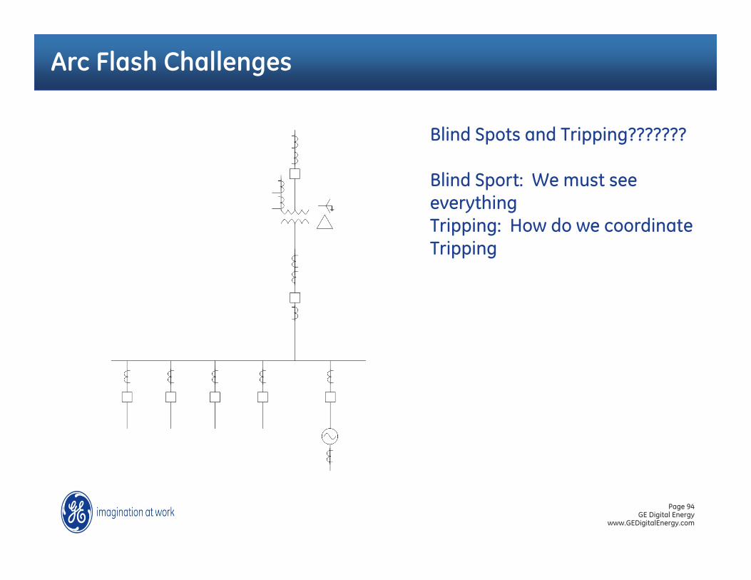
Arc Flash Challenges
Blind Spots and Tripping???????
Blind Sport: We must see everythingTripping: How do we coordinate Tripping
Page 95GE Digital Energy
www.GEDigitalEnergy.com
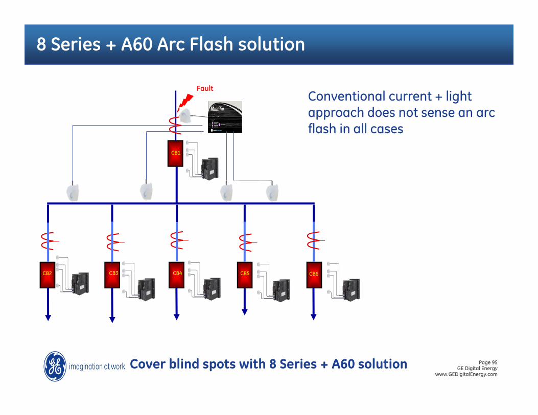
8 Series + A60 Arc Flash solution
Conventional current + light approach does not sense an arc flash in all cases
Cover blind spots with 8 Series + A60 solution
CB1
CB5CB4CB3CB2 CB6
Fault
Page 96GE Digital Energy
www.GEDigitalEnergy.com
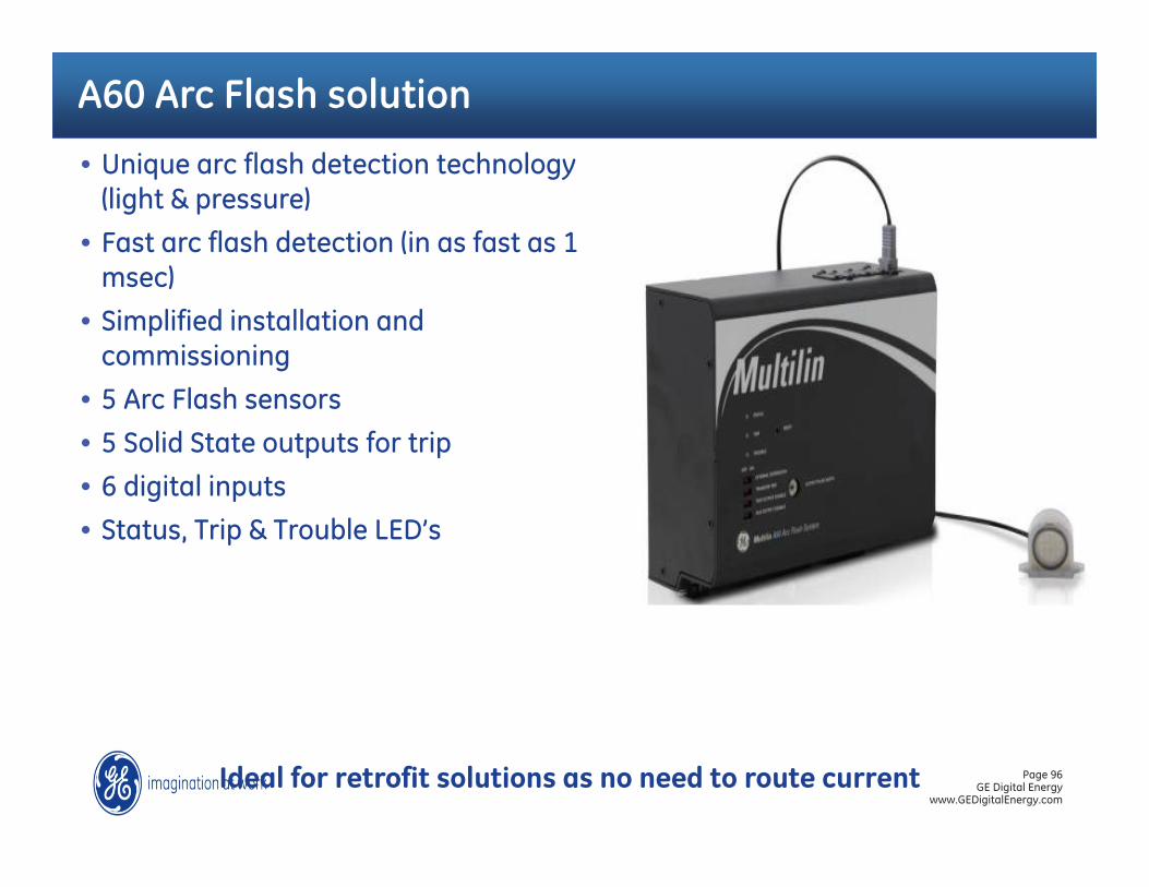
A60 Arc Flash solution
Ideal for retrofit solutions as no need to route current
• Unique arc flash detection technology (light & pressure)
• Fast arc flash detection (in as fast as 1 msec)
• Simplified installation and commissioning
• 5 Arc Flash sensors
• 5 Solid State outputs for trip
• 6 digital inputs
• Status, Trip & Trouble LED’s
Page 97GE Digital Energy
www.GEDigitalEnergy.com
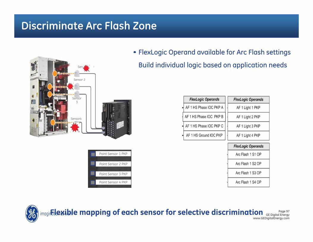
Discriminate Arc Flash Zone
• FlexLogic Operand available for Arc Flash settings
• Build individual logic based on application needs
Flexible mapping of each sensor for selective discrimination
Sensor 1
Sensor 2
Sensor 3
Sensor4
Point Sensor 1 PKP
Point Sensor 3 PKP
Point Sensor 2 PKP
Point Sensor 4 PKP

98
Lessons LearnedThrough Event Analysis

99
Incorrect Current Transformer Wiring Causes Bus Fault During
Power Transformer Energization
100100
• I have energized the transformer• As soon as I pickup load, I get a transformer
differential
The Story
101
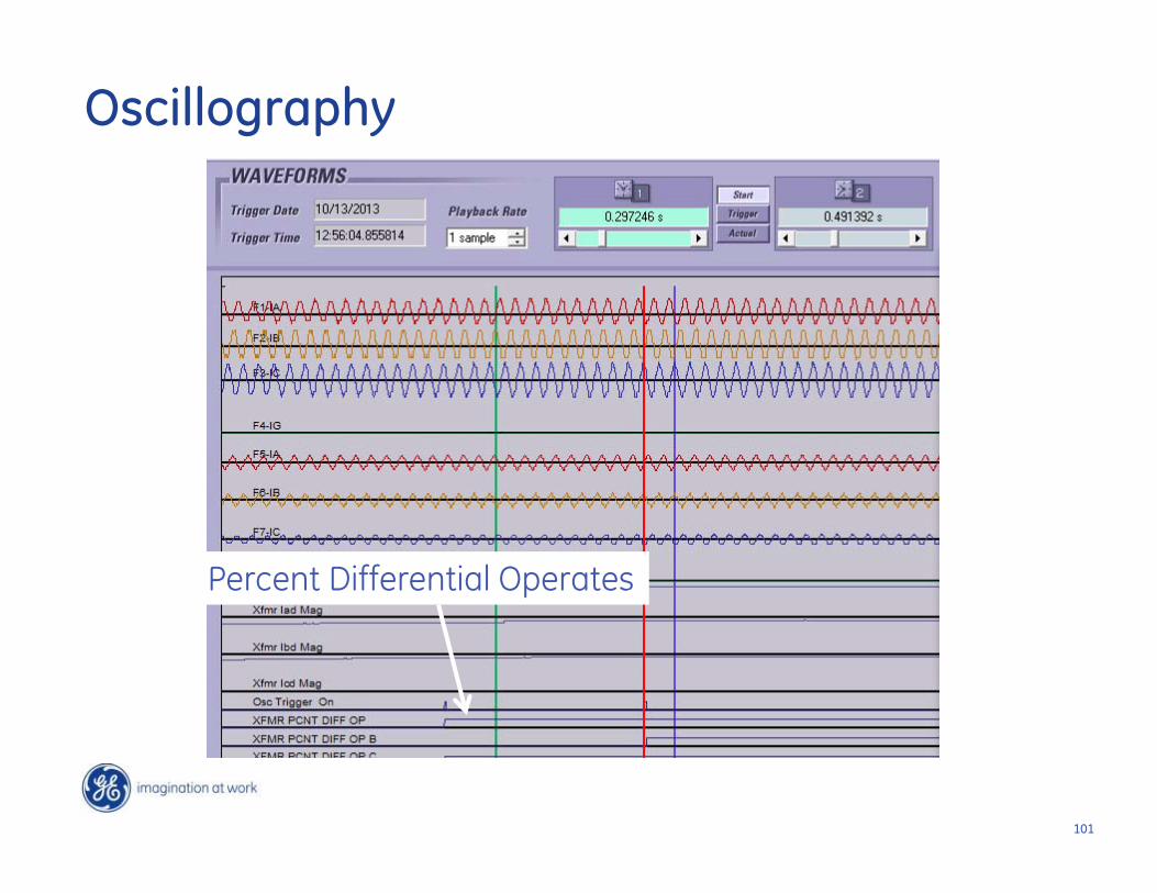
Percent Differential Operates
Oscillography
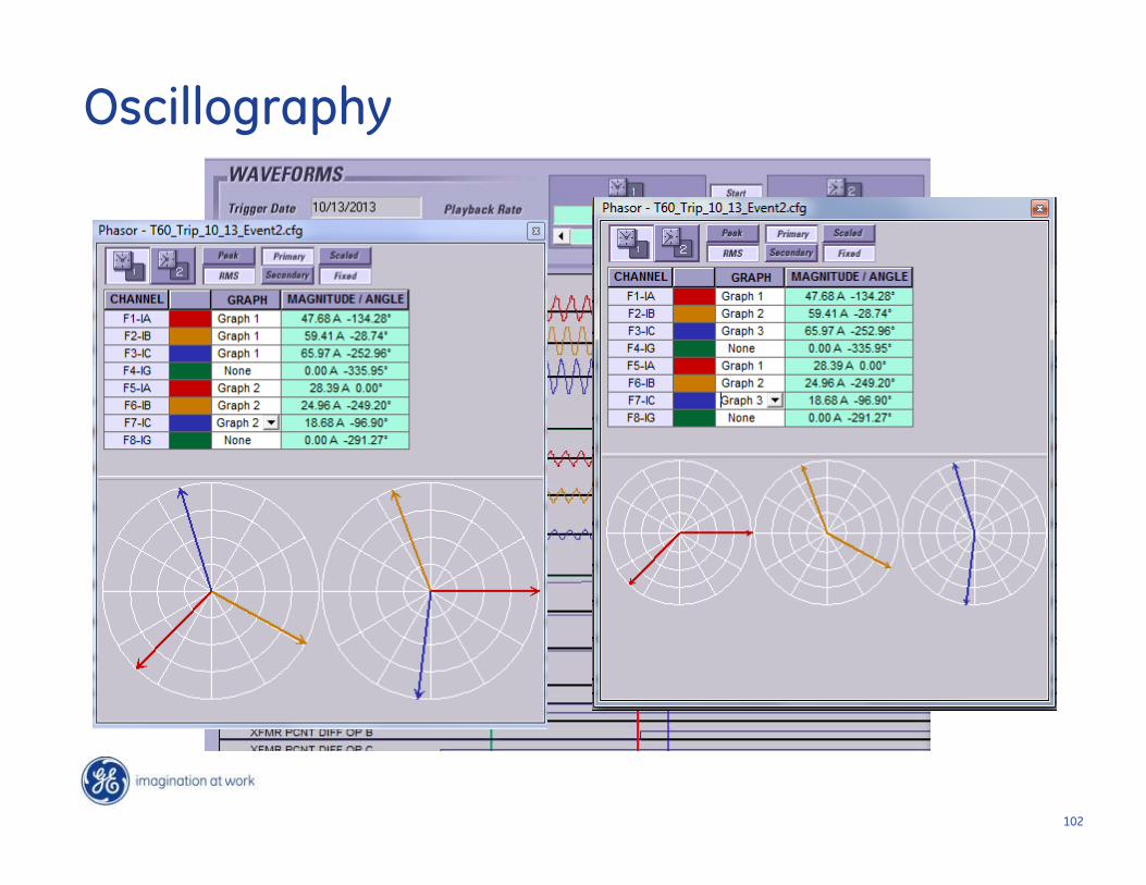
102
Oscillography
103
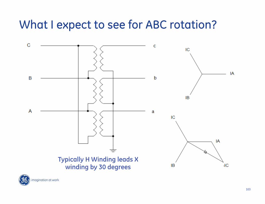
Typically H Winding leads X winding by 30 degrees
What I expect to see for ABC rotation?
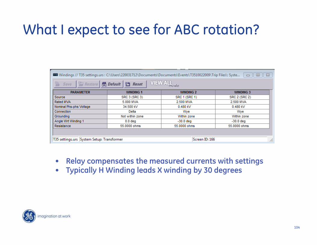
104
• Relay compensates the measured currents with settings• Typically H Winding leads X winding by 30 degrees
What I expect to see for ABC rotation?
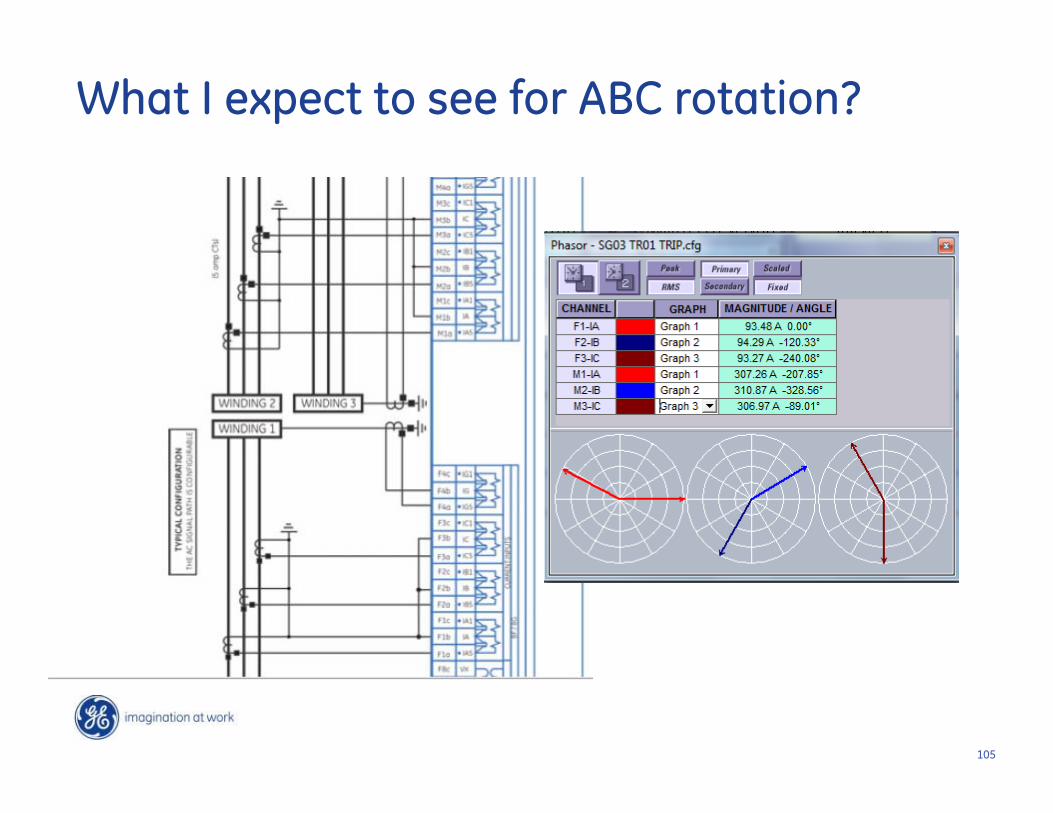
105
What I expect to see for ABC rotation?
106
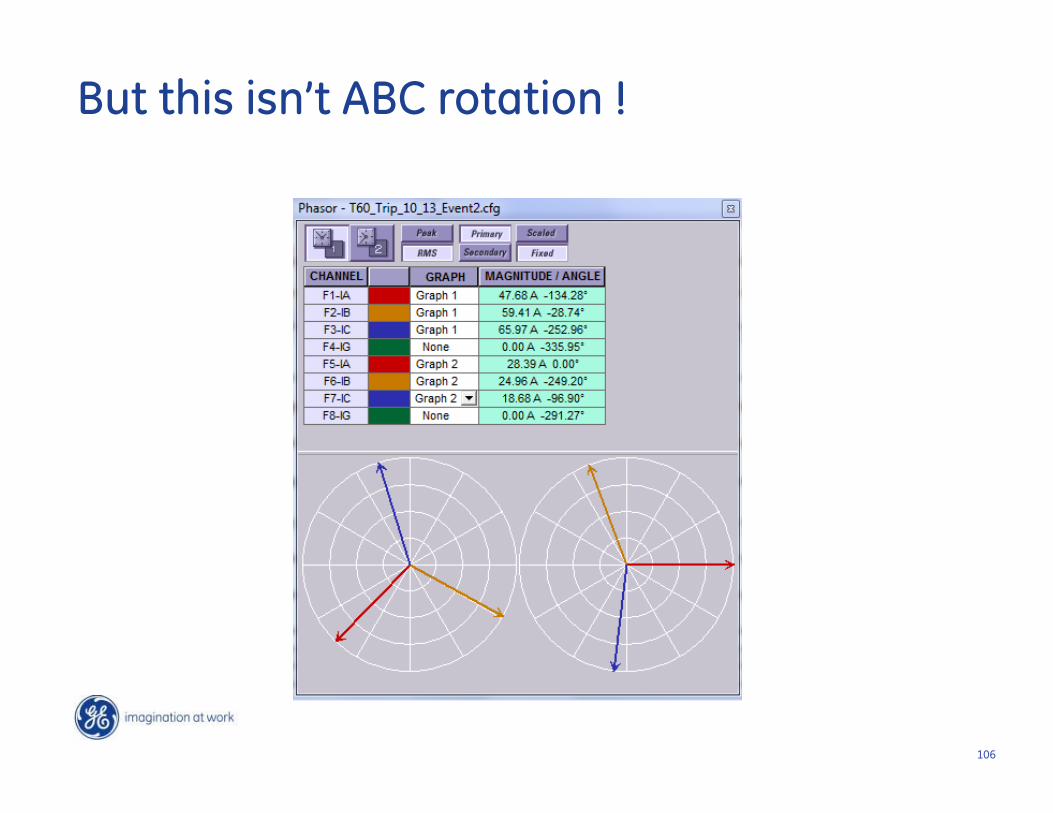
But this isn’t ABC rotation !
107
Typically H Winding lags X winding by 30 degrees on ACB rotation
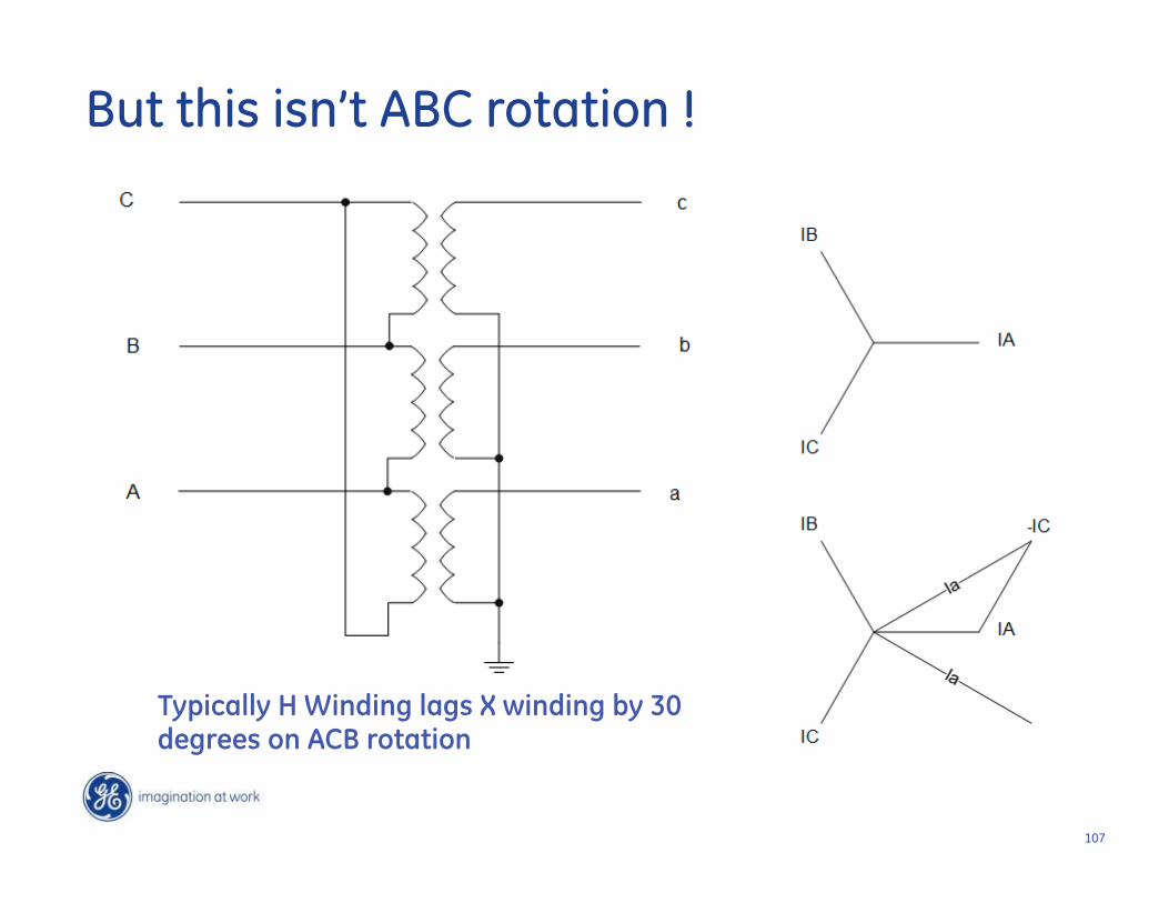
But this isn’t ABC rotation !
108
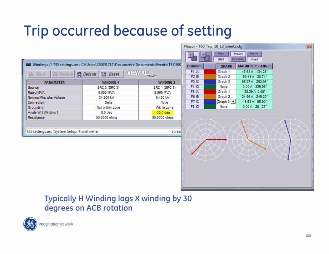
Typically H Winding lags X winding by 30 degrees on ACB rotation
Trip occurred because of setting

109
Swapping phases on the High side changes my transformer from 30 lag to
30 lead
c
a
C
A
What happens if I swap phases on my H winding?

110
Erroneous Power ReadingsUnearth Differential
Wiring Problems
111111
• Industrial customer complained of wrong power readings in transformer differential relay
• Examination of metering values showed A and C phase watts negative with B phase watts positive
• Not possible for a 3-phase motor load
The Story
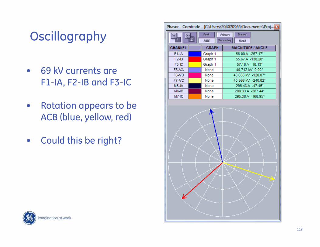
112
• 69 kV currents are F1-IA, F2-IB and F3-IC
• Rotation appears to be ACB (blue, yellow, red)
• Could this be right?
Oscillography
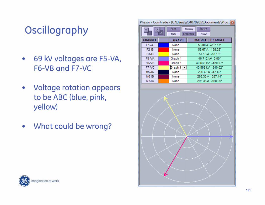
113
• 69 kV voltages are F5-VA, F6-VB and F7-VC
• Voltage rotation appears to be ABC (blue, pink, yellow)
• What could be wrong?
Oscillography
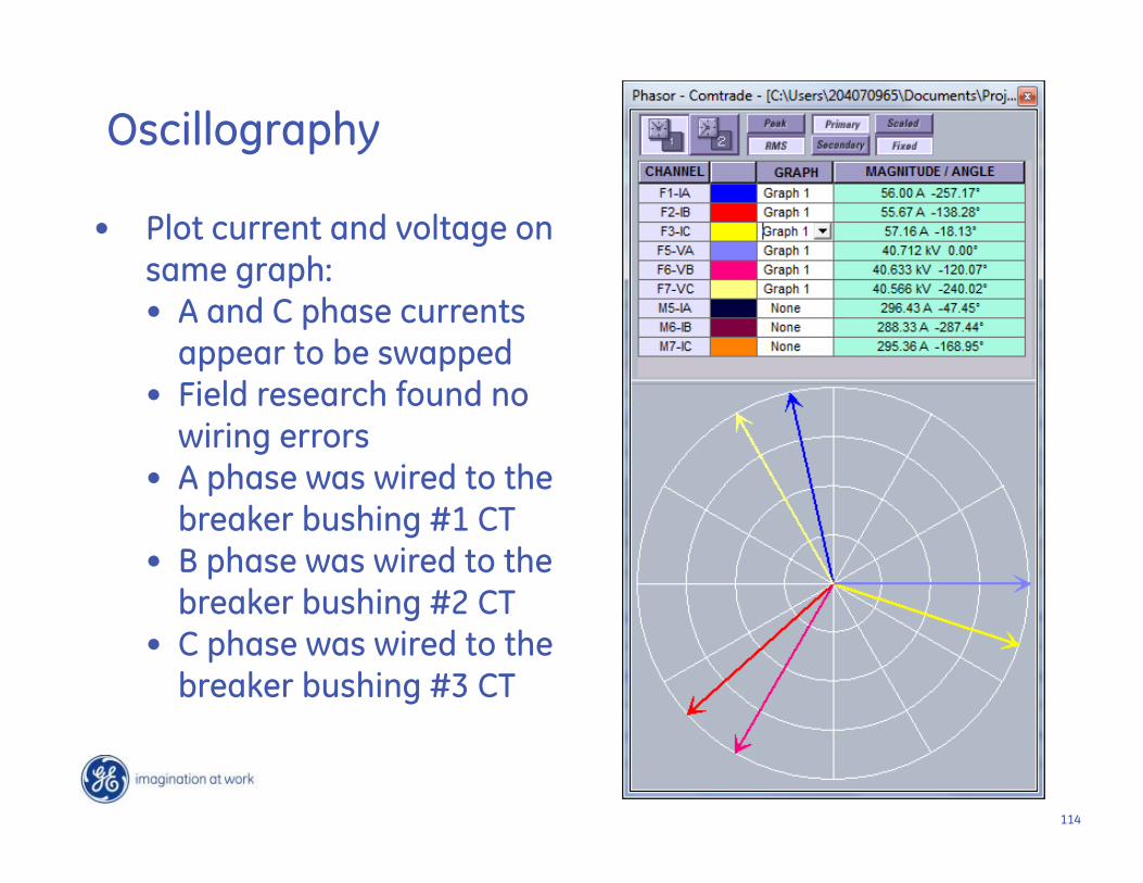
114
• Plot current and voltage on same graph:• A and C phase currents
appear to be swapped• Field research found no
wiring errors• A phase was wired to the
breaker bushing #1 CT• B phase was wired to the
breaker bushing #2 CT• C phase was wired to the
breaker bushing #3 CT
Oscillography
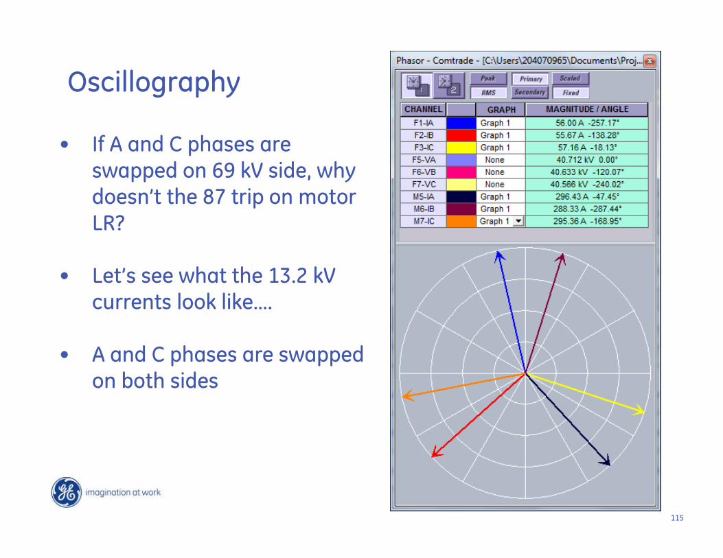
115
• If A and C phases are swapped on 69 kV side, why doesn’t the 87 trip on motor LR?
• Let’s see what the 13.2 kV currents look like….
• A and C phases are swapped on both sides
Oscillography
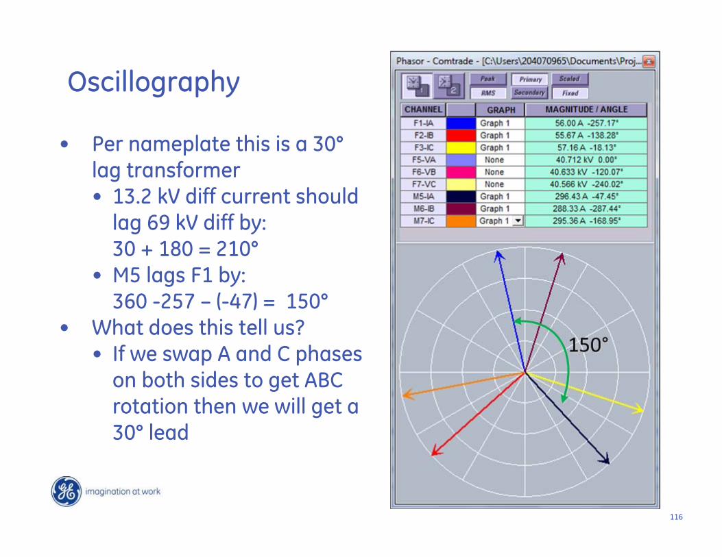
116
• Per nameplate this is a 30°lag transformer• 13.2 kV diff current should
lag 69 kV diff by: 30 + 180 = 210°
• M5 lags F1 by: 360 -257 – (-47) = 150°
• What does this tell us?• If we swap A and C phases
on both sides to get ABC rotation then we will get a 30° lead
Oscillography
117
X1X2X3
X0
H3 H2 H1
X0X1
X2
X3
H1
H2H3
Nameplate
X0
A (H3)Installed
B (H2)C (H1)A (X3)
B (X2)C (X1)
A B C
A B C
115,000 –13,800/7970 GY
20 MVA
2000/5 A
200/5 A
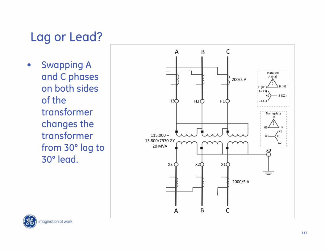
• Swapping A and C phases on both sides of the transformer changes the transformer from 30° lag to 30° lead.
Lag or Lead?
118
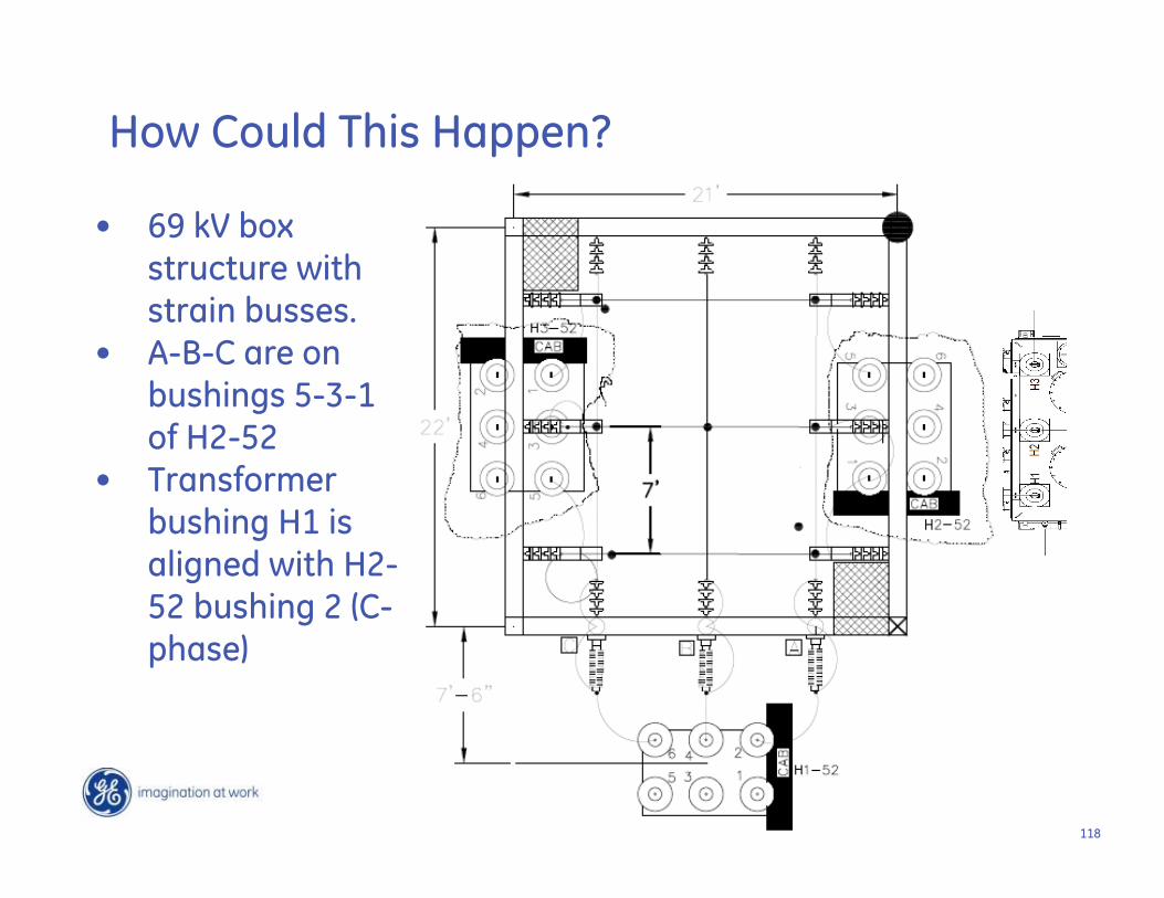
• 69 kV box structure with strain busses.
• A-B-C are on bushings 5-3-1 of H2-52
• Transformer bushing H1 is aligned with H2-52 bushing 2 (C-phase)
How Could This Happen?
119119
• Reconnect A-phase CT lead on 52-H2 to bushing 3 CT
• Reconnect C-phase CT lead on 52-H2 to bushing 1 CT
• Reconnect A-phase CT lead on Transformer to bushing X3 CT
• Reconnect C-phase CT lead on Transformer to bushing X1 CT
• Change phase shift angle to -330° (+30°)
Final Solution

120
Incorrect Current Transformer Wiring Causes Differential
Tripping During Power Transformer Energization
121121
• I’ve installed a new autotransformer with differential protection
• As soon as I energize the transformer the differential relay trips
The Story
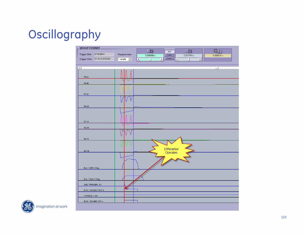
122
Oscillography
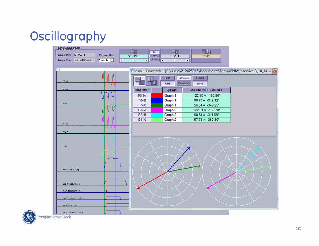
123
Oscillography
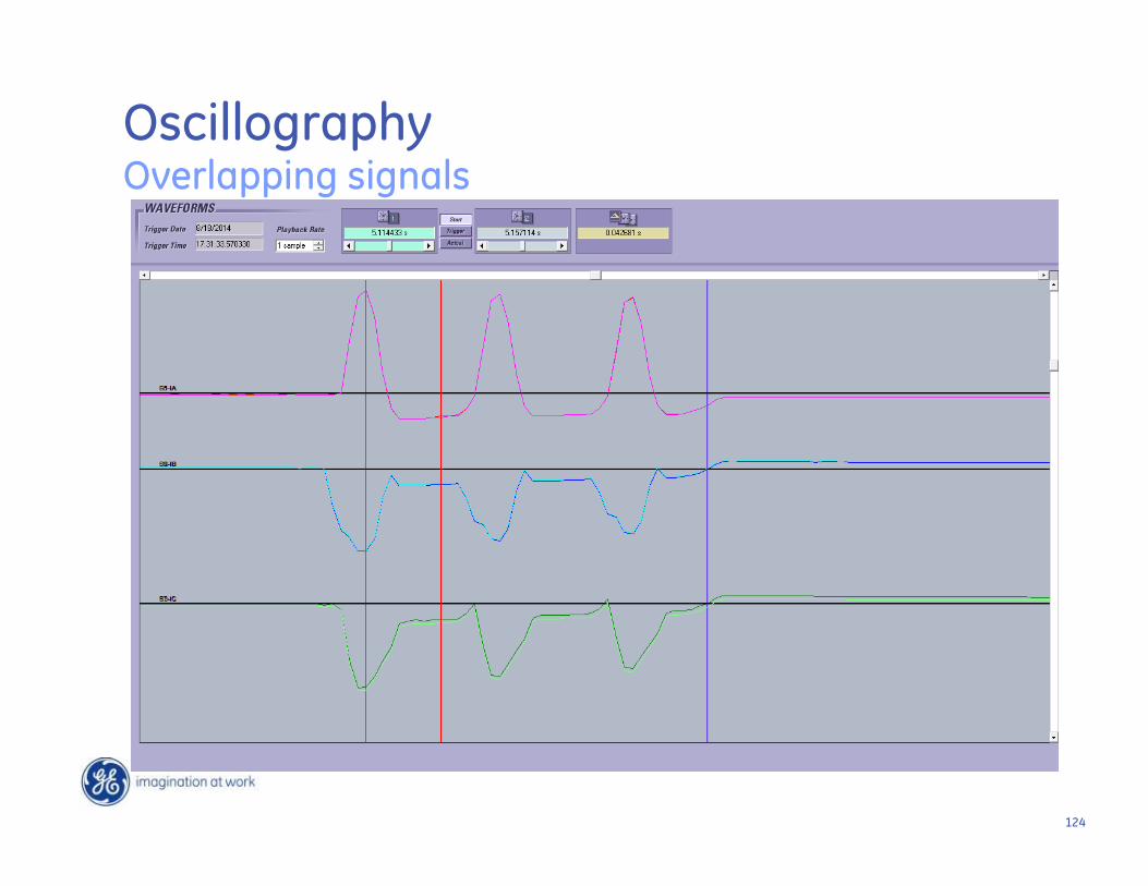
124
Oscillography Overlapping signals
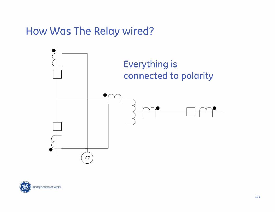
125
Everything is connected to polarity
How Was The Relay wired?
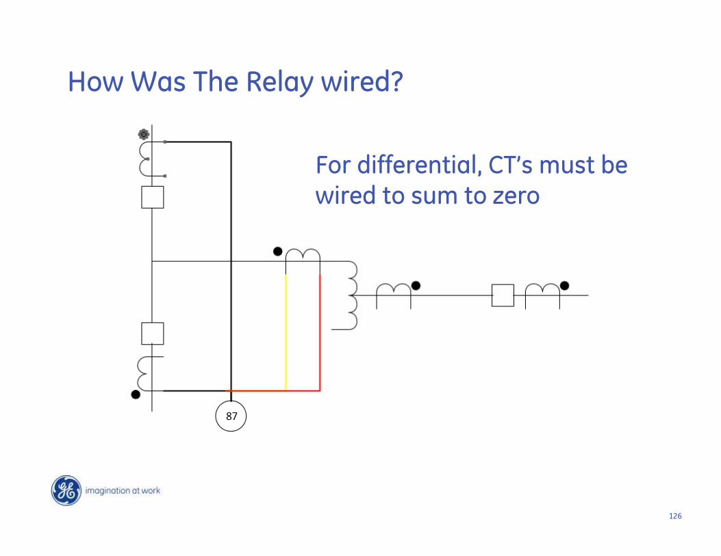
126
For differential, CT’s must be wired to sum to zero
How Was The Relay wired?
127
System Fault Causes Generator
Underfrequency Trip
128128
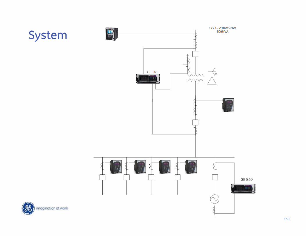
• Facility is intertied to a Utility sub-transmission system that is fed radially
• Generator tripped on under-frequency rather than separating from the utility to clear the fault
The Story
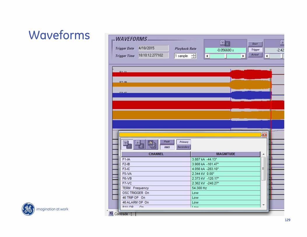
129129
Waveforms
130130
System
GE G60
131131
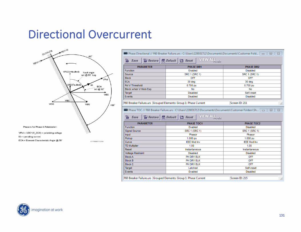
Directional Overcurrent

132
Paralleling Switchgear Trip
133133
The Story
• This relay trips every time I close the breaker• It is tripping on overcurrent• You need to send me a new relay because this
one is obviously bad
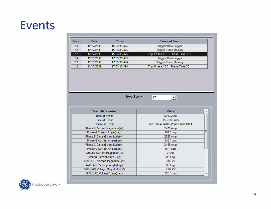
134134
Events
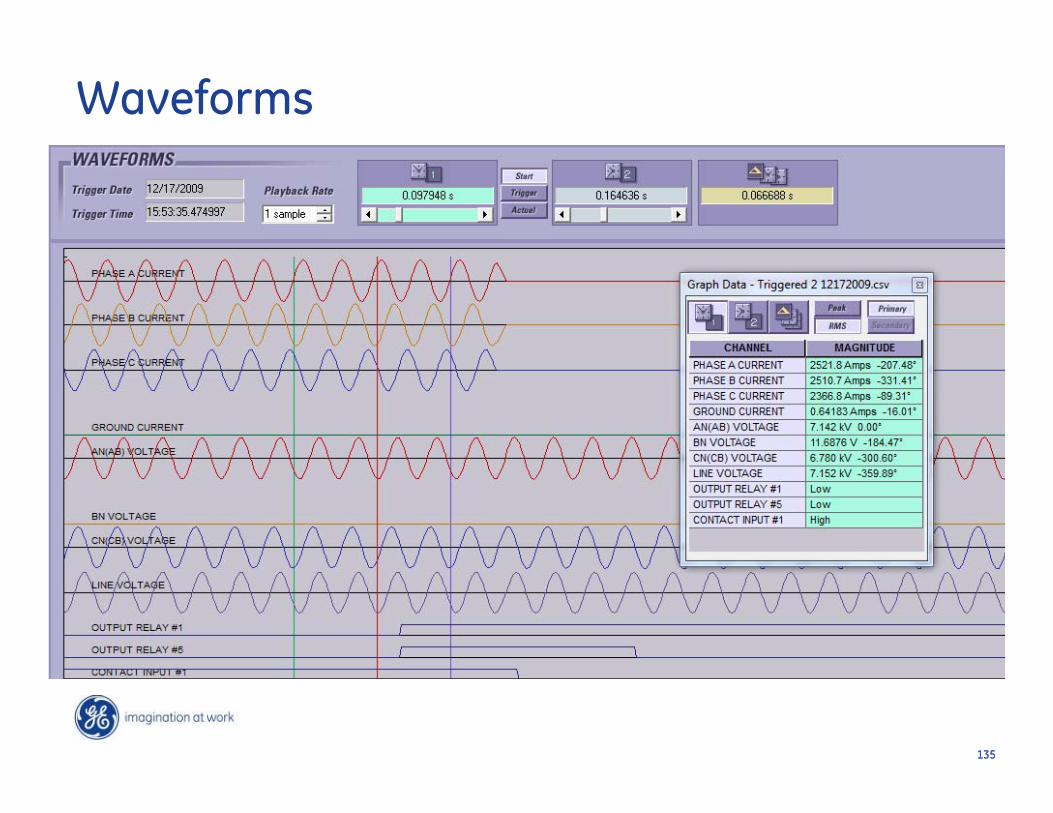
135135
Waveforms
136136
How microprocessor relays fail?
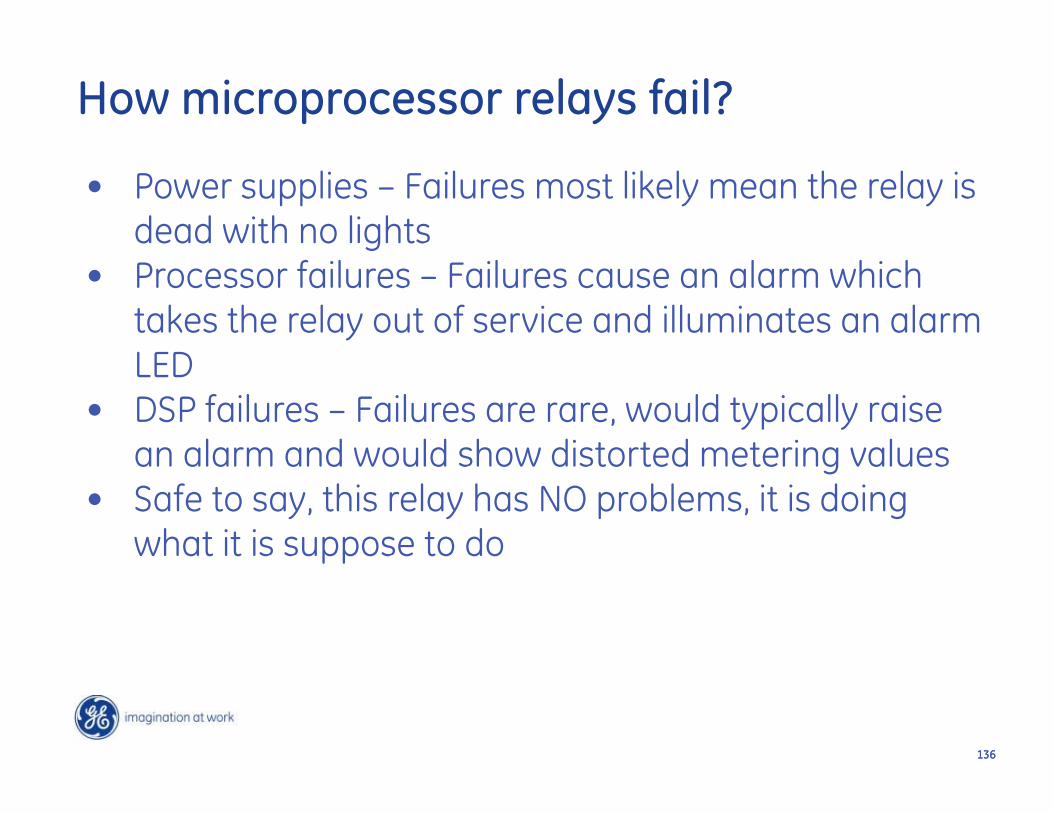
• Power supplies – Failures most likely mean the relay is dead with no lights
• Processor failures – Failures cause an alarm which takes the relay out of service and illuminates an alarm LED
• DSP failures – Failures are rare, would typically raise an alarm and would show distorted metering values
• Safe to say, this relay has NO problems, it is doing what it is suppose to do
137137
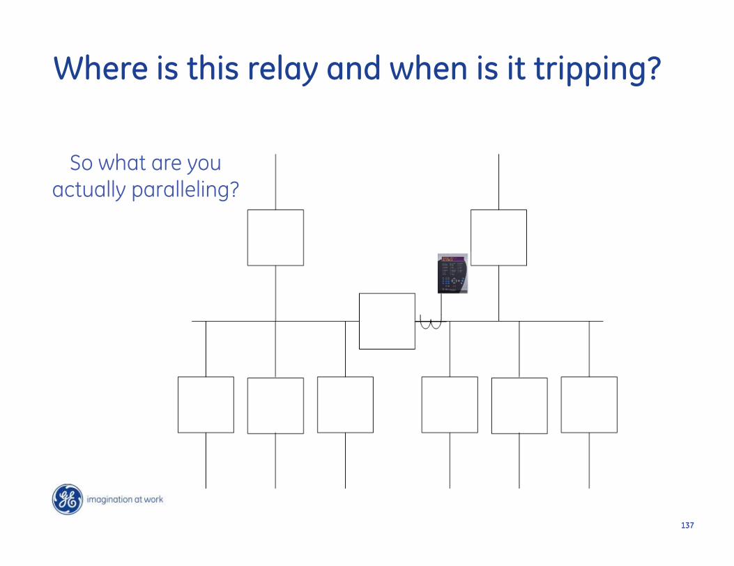
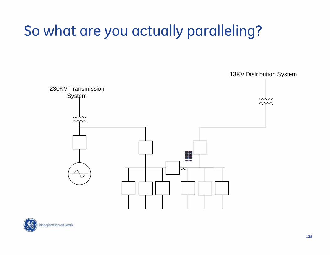
So what are you actually paralleling?
Where is this relay and when is it tripping?
138138
230KV Transmission System
13KV Distribution System
So what are you actually paralleling?

139139

Appendix

Useful Links www.gedigitalenergy.com/multilin
• For free training and how to videos: http://www.gedigitalenergy.com/Resources.htm
• For More Information on the 850 Relay: https://www.gedigitalenergy.com/multilin/catalog/850.htm
• For More Information on the 869 Relay: https://www.gedigitalenergy.com/multilin/catalog/869.htm
• For More Information on the 845 Relay: https://www.gedigitalenergy.com/multilin/catalog/845.htm
• For More Information on the UR Relay: https://www.gedigitalenergy.com/multilin/catalog/urfamily.htm
• For More Information on the C90 Plus:https://www.gedigitalenergy.com/multilin/catalog/c90plus.htm
• For More Information on the A60:https://www.gedigitalenergy.com/multilin/catalog/a60.htm
• For More Information on the Multilink Ethernet Switches: https://www.gedigitalenergy.com/multilin/catalog/multilink.htm
• For More Information on the MultiSync100 GPS Clock: https://www.gedigitalenergy.com/Multilin/catalog/multisync.htm
• For More Information on the Viewpoint Monitoring Software: https://www.gedigitalenergy.com/multilin/enervista/viewpoint/monitoring.htm