Embed Size (px)
Citation preview
Drive Technology \ Drive Automation \ System Integration \ Services
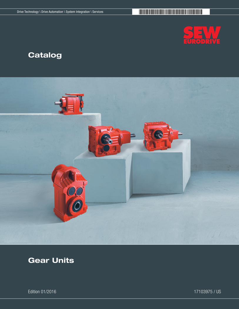
Gear Units
Edition 01/2016 17103975 / US
Catalog

SEW-EURODRIVE—Driving the worldSEW-EURODRIVE—Driving the world
Contents
3Gear Units – 2016
1
2
3
4
5
6
7
8
9
10
11
12
13
14
15
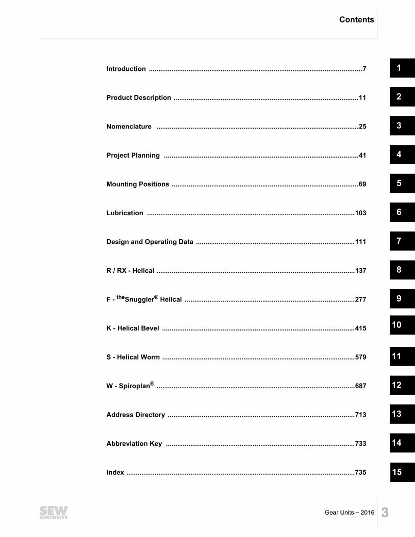
Introduction .................................................................................................................7
Product Description ..................................................................................................11
Nomenclature ...........................................................................................................25
Project Planning .......................................................................................................41
Mounting Positions ...................................................................................................69
Lubrication ..............................................................................................................103
Design and Operating Data ....................................................................................111
R / RX - Helical .........................................................................................................137
F - theSnuggler® Helical ..........................................................................................277
K - Helical Bevel ......................................................................................................415
S - Helical Worm ......................................................................................................579
W - Spiroplan® .........................................................................................................687
Address Directory ...................................................................................................713
Abbreviation Key ....................................................................................................733
Index .........................................................................................................................735
Contents
4 Gear Units – 2016
1 Introduction .............................................................................................................71.1 The SEW-EURODRIVE Group of Companies................................................71.2 Products and systems from SEW-EURODRIVE ............................................81.3 Additional documentation .............................................................................101.4 Copyright ......................................................................................................10
2 Product Description..............................................................................................112.1 General information ......................................................................................112.2 Environmental protection ..............................................................................142.3 Extended storage..........................................................................................152.4 Important ordering information......................................................................162.5 Nameplate information..................................................................................192.6 Input components .........................................................................................20
3 Nomenclature .......................................................................................................253.1 Overview.......................................................................................................253.2 Shaft and flange combinations .....................................................................303.3 Input assemblies...........................................................................................39
4 Project Planning ...................................................................................................414.1 List of application variables...........................................................................414.2 Project planning assistance ..........................................................................424.3 Selection procedure......................................................................................434.4 Gear efficiency and thermal losses...............................................................444.5 Service factor and inertia ..............................................................................464.6 Axial forces and overhung loads...................................................................514.7 AM adapter with IEC/NEMA motor ...............................................................554.8 AR adapter with torque limiting coupling ......................................................574.9 AD input shaft ..............................................................................................604.10 RM - extended bearing housing....................................................................644.11 DUO - Oil aging monitor ...............................................................................67
5 Mounting Positions...............................................................................................695.1 General information ......................................................................................695.2 R-series helical .............................................................................................725.3 F-series helical-parallel.................................................................................775.4 K-series helical-bevel....................................................................................805.5 S-series helical-worm ...................................................................................935.6 SPIROPLAN® ...............................................................................................99
6 Lubrication ..........................................................................................................1036.1 Greases and table keys ..............................................................................1036.2 Lubricant tables ..........................................................................................1046.3 Fill quantities...............................................................................................106
7 Design and Operating Data................................................................................1117.1 Tolerances ..................................................................................................1117.2 Foot or flange mounting..............................................................................1127.3 Torque arm mounting .................................................................................1127.4 TorqLOC® mounting system ......................................................................113
Contents
5Gear Units – 2016
7.5 Hollow shaft with key ..................................................................................1157.6 Hollow shaft with key - Standard design.....................................................1167.7 Hollow shaft with key - Recommended design ...........................................1197.8 Bolts and eyebolts ......................................................................................1247.9 Reduced backlash ......................................................................................1257.10 Flange detail dimensions - RF.. and R..F ..................................................1267.11 Flange detail dimensions - FF.., KF.., SF.. and WF.. .................................1277.12 Flange detail dimensions - FAF.., KAF.., SAF.. and WAF.. .......................1287.13 Hollow shaft covers.....................................................................................1297.14 Chamfers on hollow shafts .........................................................................1307.15 General dimension notes............................................................................1317.16 Explanation of dimensions..........................................................................1327.17 Overview of selection tables .......................................................................135
8 R / RX - Helical.....................................................................................................1378.1 R/RX.. AM...................................................................................................1378.2 R / RX.. AD .................................................................................................1738.3 R/RX.. AM.. [NEMA dimensions] ................................................................2208.4 R/RX..AM.. [IEC dimensions]......................................................................2638.5 R.. R.. AM.. [compound dimensions] ..........................................................2668.6 R/RX.. AD.. [dimensions] ............................................................................2678.7 R.. R.. AD.. [compound dimensions]...........................................................2698.8 R/RX.. AD/P [dimensions]...........................................................................2708.9 R.. AR.. [dimensions] ..................................................................................2728.10 Output shaft sizes .......................................................................................274
9 F - theSnuggler® Helical ......................................................................................2779.1 F.. AM .........................................................................................................2779.2 F.. AD..........................................................................................................3059.3 F.. AM.. [NEMA dimensions].......................................................................3449.4 F..AM.. [IEC dimensions)]...........................................................................3989.5 F.. R.. AM.. [compound dimensions]...........................................................4019.6 F.. AD.. [dimensions] ..................................................................................4029.7 F.. R.. AD.. [compound dimensions] ...........................................................4049.8 F.. AD../P [dimensions] ...............................................................................4059.9 F.. AR.. [dimensions] ..................................................................................4079.10 Output shaft sizes .......................................................................................409
10 K - Helical Bevel ..................................................................................................41510.1 K.. AM.........................................................................................................41510.2 K.. AD .........................................................................................................44910.3 K.. AM.. [NEMA dimensions] ......................................................................49210.4 K.. AM.. [IEC dimensions]...........................................................................56210.5 K.. R.. AM.. [compound NEMA dimensions] ...............................................56510.6 K.. AD.. [dimensions] ..................................................................................56610.7 K.. R.. AD.. [compound dimensions]...........................................................56810.8 K.. AD../P [dimensions]...............................................................................56910.9 K.. AR.. [dimensions] ..................................................................................57110.10 Output shaft sizes .......................................................................................573
Contents
6 Gear Units – 2016
11 S - Helical Worm..................................................................................................57911.1 S.. AM ........................................................................................................57911.2 S.. AD ........................................................................................................59211.3 S.. AM.. [NEMA dimensions] ......................................................................61211.4 S.. AM.. [IEC dimensions]...........................................................................64611.5 S.. R.. AM.. [compound dimensions] ..........................................................64811.6 S.. AD.. [dimensions] ..................................................................................64911.7 S.. R.. AD.. [compound dimensions]...........................................................65111.8 S.. AD../P [dimensions]...............................................................................65211.9 S.. AR.. [dimensions] ..................................................................................65311.10 Mechanical ratings......................................................................................65411.11 Output shaft sizes .......................................................................................682
12 W - Spiroplan®.....................................................................................................68712.1 W.. AM........................................................................................................68712.2 W.. AD ........................................................................................................69112.3 W.. AM.. [NEMA dimensions] .....................................................................69512.4 W.. AM.. [IEC dimensions]..........................................................................70412.5 W.. AD.. [dimensions] .................................................................................70512.6 W.. AR.. [dimensions] .................................................................................70712.7 Output shaft sizes .......................................................................................708
13 Address Directory...............................................................................................713
14 Abbreviation Key ................................................................................................733
15 Index.....................................................................................................................735
1The SEW-EURODRIVE Group of CompaniesIntroduction
7Gear Units – 2016
1
2
3
4
5
6
7
8
9
10
11
12
13
14
15
16
17
18
19
20
21
22
1 Introduction1.1 The SEW-EURODRIVE Group of Companies
Global presenceSEW-EURODRIVE is driving the world with innovative drive solutions for all branches andevery application. Products and systems from SEW-EURODRIVE are used in a multitude ofapplications worldwide. Be it in the automotive, building materials, food and beverage ormetal-processing industry, the decision to use drive technology "made by SEW-EURODRIVE" stands for reliability and quality.
We currently have 15 manufacturing plants, 79 assembly plants in 48 countries, and acomprehensive range of services that represents our commitment to outstanding quality.
Complete solutionsThe SEW-EURODRIVE modular concept offers millions of combinations. This wideselection enables you to choose the correct drive for all applications, based upon your re-quired speed, torque, available space, and ambient conditions. We offer many gradual sizesof gear units so there is always a unit that closely matches your torque requirement to pro-vide the best economic solution and to prevent unnecessary oversizing.
Gearmotors are powered by MOVITRAC® or MOVIDRIVE® frequency inverters orMOVIAXIS® multi-axis servo inverters, providing a single-source solution for all of yourneeds. Whether its electronics or mechanical systems, SEW-EURODRIVE is responsiblefor the complete development, production and assembly of all products in order to providethe utmost in flexibility.
Products of the servo drive system provide precision and dynamics, including low backlashservo gear units, compact servomotors, and MOVIAXIS® multi-axis servo inverters. Fromsingle-axis or multi-axis applications all the way to synchronized processes, servo drivesystems by SEW-EURODRIVE offer a flexible and customized implementation of yourapplication.
For economical decentralized installations, SEW-EURODRIVE offers components such asMOVIMOT®, the gearmotor with integrated frequency inverter or MOVI-SWITCH®, thegearmotor with integrated switching and protection. Our hybrid cables have been designedspecifically to ensure cost-effective solutions, independent of the system size or system type.
The latest developments from SEW-EURODRIVE include: MOVITRANS® - contactlessenergy transfer, MOVIPRO® - decentralized drive control, and MOVIFIT®- decentralizedintelligence.
Power, quality, and sturdy design define the industrial gear units available from SEW-EURODRIVE. With high torque capacity and a modular concept, the industrial gear unitsonce again provide optimum adaptation of a standard product for a wide range ofdemanding applications.
Worldwide partnerOur global presence, extensive product range, and broad spectrum of services make SEW-EURODRIVE the ideal partner for demanding applications in all industries and applications.
1 Products and systems from SEW-EURODRIVEIntroduction
8 Gear Units – 2016
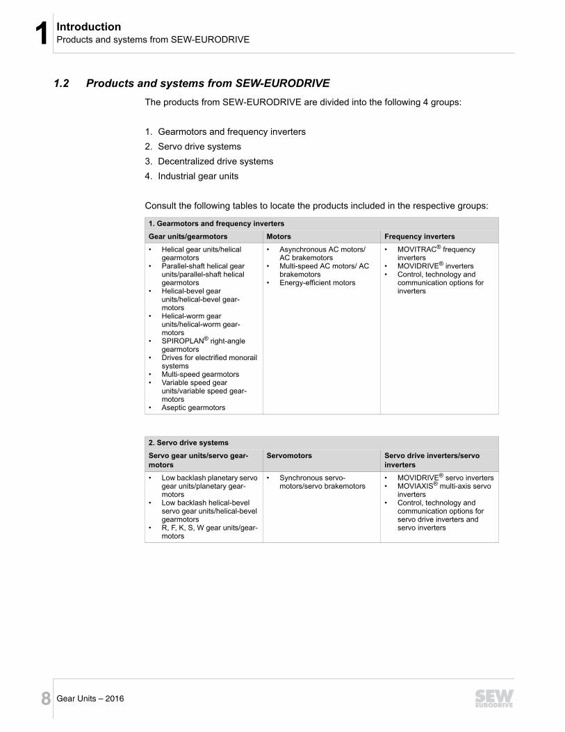
1.2 Products and systems from SEW-EURODRIVE
The products from SEW-EURODRIVE are divided into the following 4 groups:
1. Gearmotors and frequency inverters
2. Servo drive systems
3. Decentralized drive systems
4. Industrial gear units
Consult the following tables to locate the products included in the respective groups:
1. Gearmotors and frequency inverters
Gear units/gearmotors Motors Frequency inverters
• Helical gear units/helical gearmotors
• Parallel-shaft helical gear units/parallel-shaft helical gearmotors
• Helical-bevel gear units/helical-bevel gear-motors
• Helical-worm gear units/helical-worm gear-motors
• SPIROPLAN® right-angle gearmotors
• Drives for electrified monorail systems
• Multi-speed gearmotors• Variable speed gear
units/variable speed gear-motors
• Aseptic gearmotors
• Asynchronous AC motors/ AC brakemotors
• Multi-speed AC motors/ AC brakemotors
• Energy-efficient motors
• MOVITRAC® frequency inverters
• MOVIDRIVE® inverters• Control, technology and
communication options for inverters
2. Servo drive systems
Servo gear units/servo gear-motors
Servomotors Servo drive inverters/servo inverters
• Low backlash planetary servo gear units/planetary gear-motors
• Low backlash helical-bevel servo gear units/helical-bevel gearmotors
• R, F, K, S, W gear units/gear-motors
• Synchronous servo-motors/servo brakemotors
• MOVIDRIVE® servo inverters• MOVIAXIS® multi-axis servo
inverters• Control, technology and
communication options for servo drive inverters and servo inverters
1Products and systems from SEW-EURODRIVEIntroduction
9Gear Units – 2016
1
2
3
4
5
6
7
8
9
10
11
12
13
14
15
16
17
18
19
20
21
22
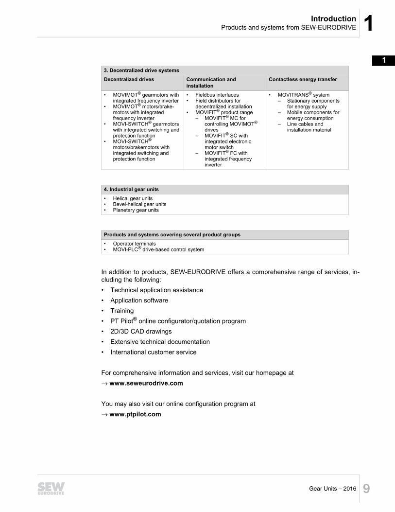
In addition to products, SEW-EURODRIVE offers a comprehensive range of services, in-cluding the following:
• Technical application assistance
• Application software
• Training
• PT Pilot® online configurator/quotation program
• 2D/3D CAD drawings
• Extensive technical documentation
• International customer service
For comprehensive information and services, visit our homepage at
www.seweurodrive.com
You may also visit our online configuration program at
www.ptpilot.com
3. Decentralized drive systems
Decentralized drives Communication and installation
Contactless energy transfer
• MOVIMOT® gearmotors with integrated frequency inverter
• MOVIMOT® motors/brake-motors with integrated frequency inverter
• MOVI-SWITCH® gearmotors with integrated switching and protection function
• MOVI-SWITCH® motors/brakemotors with integrated switching and protection function
• Fieldbus interfaces• Field distributors for
decentralized installation• MOVIFIT® product range
– MOVIFIT® MC for controlling MOVIMOT® drives
– MOVIFIT® SC with integrated electronic motor switch
– MOVIFIT® FC with integrated frequency inverter
• MOVITRANS® system– Stationary components
for energy supply– Mobile components for
energy consumption– Line cables and
installation material
4. Industrial gear units
• Helical gear units • Bevel-helical gear units• Planetary gear units
Products and systems covering several product groups
• Operator terminals• MOVI-PLC® drive-based control system
1 Additional documentationIntroduction
10 Gear Units – 2016
1.3 Additional documentation
Content of this publication
This "Gear Units" catalog provides a detailed description of the following product groupsfrom SEW-EURODRIVE:
• R.., F.., K.., S.., and SPIROPLAN® W gear units in combination with
• AM adapter• AD input shaft assembly• AR Torque limiting coupling
For information on options for the motors, refer to the catalogs "DR.. AC Motors".
For additional information on R.., F.., K.., S.. and SPIROPLAN® W gear units in combinationwith the AQ adapter for servomotors, refer to the "Servo Gear Units" catalog.
Additional documentation
The following catalogs are available from SEW-EURODRIVE in addition to this "Gear Units"catalog:
• Servo gear units
• Synchronous servo gearmotors
• DRN.. gearmotors
• DR.. AC motors
• MOVIMOT® gearmotors
These catalogs offer the following information:
• Product descriptions
• Technical data and inverter assignments
• Important information about tables and dimension sheets
• Description of the different types
• Selection tables
• Dimension sheets
• Technical data
• Notes on adapter mounting
1.4 Copyright
© 2016 - SEW-EURODRIVE. All rights reserved.
Copyright law prohibits the unauthorized duplication, modification, distribution, and use ofthis document, in whole or in part.