Embed Size (px)
Citation preview

1/0
2- 2013
sqfasfsa
1
DOM
Measuring range: 0.5…36 L/h and 150…2500 L/min
Viscosity range: 0…1000 cP(higher with special cut rotors)
Accuracy: ±0.2 %…1% of reading
Material: aluminium, ductile iron or stainless steel
pmax: 400 bar; tmax: 120 °C
Pulse output, LCD display, 4…20 mA, alarms, mechanical register
Gear Wheel FIowmeter for Viscous Liquids
measuring
•
monitoring
•
analysing
KOBOLD Messring GmbHNordring 22-24D-65719 Hofheim/Ts.
Head Offi ce: +49 (0) 6192 299-0
+49 (0) 6192 23398 [email protected] www.kobold.com
KOBOLD companies worldwide:
ARGENTINA, AUSTRIA, BELGIUM, BULGARIA, CANADA, CHILE, CHINA, COLUMBIA, CZECHIA, DOMINICAN REPUBLIC, EGYPT, FRANCE, GERMANY, GREAT BRITAIN, HUNGARY, INDIA, INDO-NESIA, ITALY, MALAYSIA, MEXICO, NETHERLANDS, PERU, POLAND, ROMANIA, SINGAPORE, SOUTH KOREA, SPAIN, SWITZERLAND, TAIWAN, THAILAND, TUNISIA, TURKEY, USA, VIETNAM

2 www.kobold.com 1/0
2- 2013
DOM-A20... DOM-A60
Body/fl anges: aluminium
Gear wheels: aluminium
Bearing: hardened steel rollers
(only for lubricating fuels or oil)
DOM-S, DOM-H
Body/fl anges: stainless steel 1.4401 (SS 316)
Gear wheels: stainless steel 1.4401 (SS 316)
Bearing: ceramic
DOM-D
Body/fl anges: ductile iron
Gear wheels: aluminium
Bearing: hardened steel rollers
(only for lubricating fuels or oil)
O-Rings: FPM (standard): -15 ... +120 °C
EPR (ethylene propylene rubber):
-20 ... +120 °C (for ketones only)
PTFE encapsulated FPM: -20 ... +120 °C
NBR: -20 ... +100 °C
Cover: glass reinforced nylon, stainless steel
(options HE, DE)
Accuracy: ±1% of reading (DOM-x05…DOM-x15)
± 0.5% of reading (DOM-x20…DOM-x35)
± 0.2% of reading (DOM-x40…DOM-x60
turndown 15 : 1)
Repeatability: typ. ± 0.03 %
Protection class: IP 66/67
Temperature range: -20 °C ... +80 °C for options L0, Z and B
and -20 °C ... +120 °C for pulse output,
for options Z and B with cooling fi ns
and for option M
Cable entry: M 20 x 1.5 (standard), ½" NPT adapter
(option)
ATEX-approval
(option Z4): II 2G EEx ia IIB T4 (-20 °C ≤ Ta ≤ +60 °C
(option HE, DE): II 2G Ex d IIB T6 (-20°C ≤ Ta ≤ +70°C)
II 2G Ex d IIB T4 (-20°C ≤ Ta ≤ +120°C)
I M2 Ex d I Mb (st. steel models only)
Principle of Operation
The Oval Gear meters are positive displacement fl owmeters
where the passage of liquid causes two oval gears to rotate
within a precision measuring chamber and with each rotation
a fi xed volume of liquid passes through the meter. Magnets
embedded within the gears initiate a high resolution pulse
train output. The pulse output can be wired directly to proc-
ess control and monitoring equipment or can be used as an
input to instruments supplied with or fi tted directly onto the
meter.
The fl owmeter is available as a blind transmitter with pulse
output capable of interfacing to most monitoring and control
instrumentation or the meter can be fi tted with or supplied
with instruments such as totalisers, rate totalisers or batch
controllers. These instruments also have monitoring and con-
trol output options including 4-20 mA, scaled pulse, fl owrate
alarms and batch control logic (preset metering).
This technology allows precise fl ow measurement and dis-
pensing of most clean liquids regardless of their conductivity,
with other liquid characteristics having no or minimal effect on
meter performance. This metering technology does not re-
quire fl ow profi le conditioning or straightline runs as required
with alternative fl ow technologies making the installation rela-
tively compact and low cost.
Positive displacement fl owmeters are an inexpensive means
to accurately meter high viscosity clean liquids as high as 1
million centipoises however, the appropriate meter must be
sized so that the pressure drop across the primary measu-
ring elements (oval rotor), does not exceed the maximum
capability of either.
Areas of Application
For all viscous, non abrasive clean liquids like:
Petroleum Oil Chemicals
Grease Fuels Ink etc.
Pastes Water
Stainless steel fl owmeters are suited to most water based
products and chemicals and aluminum meters are suitable
for fuels, fuel oils & lubricating liquids.
Technical Details
Material DOM-A05 ... DOM-A15
Body: aluminium
Gear wheels: stainless steel 1.4401 (SS 316)
Bearing: ceramic
Maximum Pressure (threaded version)
with fl anges, maximum pressure rating as above or as per fl ange rating,
whichever is lower1) restricted to max. 40 bar with options M1, M32) restricted to max. 30 bar with options M1, M3
Model Maximum pressure [bar] DOM-A.. DOM-S.. DOM-H.. DOM-D..
DOM-x05.. 15 34 400 –
DOM-x10.. 15 34 400 –
DOM-x15.. 15 34 400 –
DOM-x20.. 681) 681) 400 –
DOM-x25.. 681) 681) 400 –
DOM-x30.. 30 30 400 –
DOM-x35.. 20 382) 300 –
DOM-x40.. 20 – – –
DOM-x45.. 12 12 – 12
DOM-x50.. 12 – – -
DOM-x55.. 10 – – 10
DOM-x60.. 10 – – -
Gear Wheel Flowmeter Model DOM
No responsibility taken for errors;
subject to change without prior notice.
liquid in transit
liquid exits the
meas. chamber
liquid entering
the meas. chamber

3www.kobold.com 1/0
2- 2013
Recommended Filter
DOM-x05 ... DOM-x15 < 75 μm micron (200 mesh)
DOM-x20 ... DOM-x35 < 150 μm micron (100 mesh)
DOM-x40 ... DOM-x60 < 350 μm micron (45 mesh)
Pulse Output
Reed switch pulse output
The reed switch output is a two wire normally open SPST
voltage free contact ideal for installations without power or for
use in hazardous area locations when Intrinsically Safe (I.S.)
philosophy is adopted.
Note: when using the reed switch output the liquid tempera-
ture must not change at a rate greater than 10 ºC per minute.
In general the reed switch life will exceed 2 billion actuations
when switching less than 5 VDC/10 mA.
Power supply: max. 30 VDC, max. 200 mA
Hall effect sensor pulse output
The hall effect sensor is a high resolution solid state 3 wire
device providing an unsourced, open collector, NPN transis-
tor output. The term “un-sourced” means that no voltage is
applied to the output from within the fl owmeter, it must be
pulled to a “high” or “on” state by between 5 - 24 VDC supplied
from an external source, typically the receiving instrument.
The pulse output between signal and -0 V is a voltage square
wave with the high level being the DC voltage available at the
open collector and the low level being -0 V.
The receiving instrument must incorporate a pull up resistor
(typically greater than 10 kΩ in most instruments) which ties
the open collector to the available DC voltage level when the
hall sensor is not energized. When energized the open collec-
tor output is pulled to ground through the emitter (-0 V).
Power supply: max. 5-24 VDC, max. 20 mA
Quadrature hall effect pulse output (...D0)
Two hall effect sensors arranged to give separate outputs out
of phase with one another.
The quadrature output is typically suited to custody transfer
applications where signal integrity verifi cation is required, it is
also used for metering bi-directional fl ow.
Power supply: max. 8 - 24 VDC, max. 20 mA
Mechanical totaliser (...M1 and ...M3)
The fl owmeters type DOM-x20 up for DOM-x60 are available
with a mechanical totaliser with either 3- or 4-digit resetable
totaliser and indication of accumulated total value. The mo-
tion of the rotors is transmitted to the mechanical register
totaliser via an interfaceing reduction gear train and dynamic
seal assembly.
Model ..Z1 ..Z3 ..Z5 ..B1
Function dual
totaliser rate
totaliser rate
totaliser batch
controller
Power source
battery-powered yes yes yes no
external (drives out put,
backlighting) 8 - 24 VDC 8 - 24 VDC 8 - 24 VDC 12 - 24 VDC
LCD display
-line 1 / no. of digits 7.5 mm/5 9 mm/8 17 mm/6 9 mm/8
-line 2 / no. of digits 3.6 mm/8 – 7 mm/8 –
selectable units yes yes yes yes
decimal point yes yes yes yes
subscripts displayed yes yes yes yes
accumulative total yes yes yes yes
resettable total yes yes yes no
Linearisation no yes no no
rate display no yes yes no
backlighting no no yes no
Input type
un-powered sensors see ZOD datasheet
powered sensors see ZOD datasheet
Outputs
4-20 mA (750 Ω) no yes no no
high/low fl ow alarm no NPN/PNP NPN no
batch end & control no no no NPN/PNP
pulse outputs NPN/PNP NPN/PNP NPN NPN/PNP
2 x SPDT relays no optional* no optional*
Installation
IP 66/67 yes yes yes yes
cable entries 1 x gland
(meter
mount)
2 x glands
(remote)
3 x M 20 3 x M 16 3 x M 20
intrinsic safe (option) no yes no no
mounting meter mount, wall, pipe or panel mounting
temperature range -20 ... +80 °C (Option: -20 ... +120 °C)
Electronic with LCD display
*replaces solid state outputs
Gear Wheel Flowmeter Model DOM
No responsibility taken for errors;
subject to change without prior notice.
4 www.kobold.com 1/0
2- 2013
0 80 160 240 320 400 480 560 DOM-x15
0 15 30 45 60 75 90 105 DOM-x10
0 5 10 15 20 25 30 35 DOM-x05
L
L
D
D
P
PDO
M-x
05/1
0
DO
M-x
15
0 0
0,01 0,2
+1.0%0-1.0%
0,02 0,4
0,03 0,6
DOM-x15
DOM-x05/10
DOM-x15
DOM-x05/10DOM-x15
DOM-x05/10
L: Light Oil
D: Diesel
P: Petrol
Pre
ssur
e D
rop
(bar
)
Acc
urac
y in
%
Flow Rate (L/h)
ΔP
bar (
PS
I)
0.2 (2.9)
0.4 (5.9)
0.6 (8.8)
0.8 (11.8)
1.0 (14.7)
1.2 (17.6)
25% 50% 75% 100%
+0.5
0
-0.5
1,000cP
500cP
60cP
3cP1cP
0.4cP
Flow Rate
Err
or in
%
Gasoline: 0.4cP
Water: 1cP
Heavy Oil: 60cP
Light Oil: 3cP
1 10 100 1000 10 000 100 000 1 000 000 0
Viscosity (cP)
Pre
ssur
e D
rop
(bar
)
1,3
1,2
1,1
1,0
0,9
0,8
0,7
0,6
0,5
0,4
0,3
0,2
0,1
1,3
1,2
1,1
1,0
0,9
0,8
0,7
0,6
0,5
0,4
0,3
0,2
0,1
Bar
Max. allowablepressure drop
Standard - 100%
Standard - 25%
Standard - 50%
Special cut - 50%
Special cut - 100%Special cut - 25%
Special cut - 10%
Special cut - 5%
L
D
P
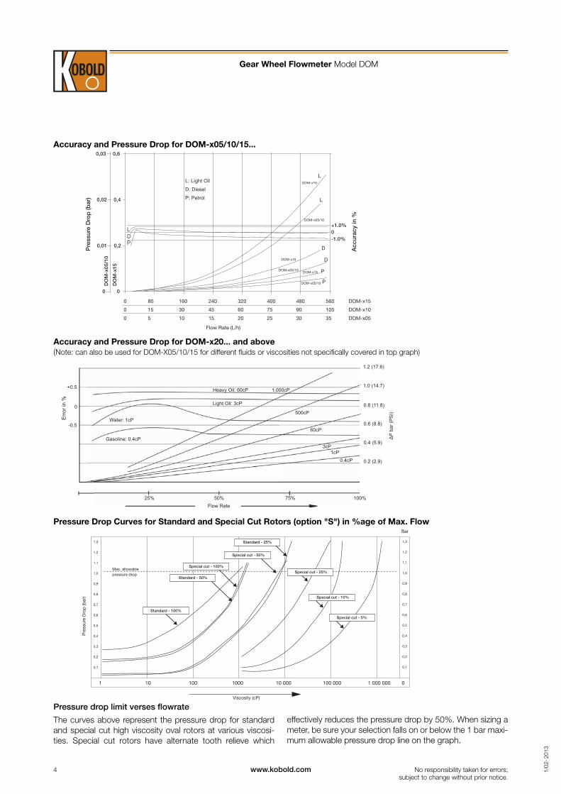
Accuracy and Pressure Drop for DOM-x20... and above
(Note: can also be used for DOM-X05/10/15 for different fl uids or viscosities not specifi cally covered in top graph)
Accuracy and Pressure Drop for DOM-x05/10/15...
Pressure Drop Curves for Standard and Special Cut Rotors (option "S") in %age of Max. Flow
Pressure drop limit verses fl owrate
The curves above represent the pressure drop for standard
and special cut high viscosity oval rotors at various viscosi-
ties. Special cut rotors have alternate tooth relieve which
effectively reduces the pressure drop by 50%. When sizing a
meter, be sure your selection falls on or below the 1 bar maxi-
mum allowable pressure drop line on the graph.
Gear Wheel Flowmeter Model DOM
No responsibility taken for errors;
subject to change without prior notice.

5www.kobold.com 1/0
2- 2013
For NPT connection change "DOM-xxxx Rx..." into "DOM-xxxx Nx"
For PPS rotors (PTFE fi lled) change "DOM-A xxxx" into "DOM-7 xxxx" and "DOM-S xxxx" into "DOM-8 xxxx"
PPS rotors not possible for "DOM-x05,-x10,-x40, -x60 and DOM-D1) not for DOM-x05, -x10, -x15, 3-digit recommended for DOM-x20, -x25, 4-digit recommended for DOM-x25 and larger; 2) not available for DOM-x05, -x10,
-x15, -x20, only available for DOM-A.. Option 'R' not available with DOM-A25..; 3) only available for DOM-A20.. to DOM-A60.., DOM-S15.. to DOM-S35.. and
DOM-D..; 4) should be chosen when using DOM instrinsically safe circuits as "simple apparatus".; 5) not available with Ductile iron housing
Meas. range[L/min]
Connec-tion
female
Housing material O-ringmaterial Electronics Option
Aluminium Stainless steel Ductile iron
0.5 - 36 L/h G ¹⁄8 DOM-A05H R1 DOM-S05H R1 –
1 = FPM
(stan-
dard)
2 = EPR
3 = PTFE
encaps.
FPM
4 = NBR
R04)= Reed switch pulse
output
H0 = Hall sensor (NPN)/ reed
switch pulse output
HE5)= as HO + ATEX (Exd)
D0 = Quad Hall sensor 2
phased outputs (NPN)
DE5)= as DO + ATEX (Exd)
L0 = 4 ... 20 mA loop
powered analogue
output
LE = as LO + ATEX (Exd)
Z1 = dual LCD totaliser,
pulse output (ZOD-Z1)
Z3 = LCD totaliser, rate,
outputs: 4-20 mA,
alarm, pulse (ZOD-Z3)
Z4 = Electronics "Z3" +
ATEX (Exi)
Z5 = dual LCD totaliser/rate,
outputs: alarm, pulse
(ZOD-Z5)
B1 = LCD batch controller,
totaliser, pulse output
(ZOD-B1)
M1 = mech. totaliser 3-digit1)
M3 = mech. totaliser 4-digit1)
XX = special option,
specifi ed in clear text
0 = without
A2) = coupled
with air
eliminator-
strainer
ZAL
C = cooling fi n
for LCD
electronic
D2) = option
A + C
R2) = option A
+ check
valve
E2) = option
R + C
S3)= special cut
rotors for
higher
viscosities
Y = special op-
tion (specify
in clear text)
2 - 100 L/h G ¼ DOM-A10H R2 DOM-S10H R2 –
15 - 550 L/h G ³⁄8 DOM-A15H R3 DOM-S15H R3 –
1 - 40 G ½ DOM-A20H R4 DOM-S20H R4 –
10 - 150 G 1 DOM-A25H R6 DOM-S25H R6 –
15 - 250 G 1½ DOM-A30H R8 DOM-S30H R8 –
30 - 450 G 2 DOM-A35H R9 DOM-S35H R9 –
50 - 580 G 2 DOM-A40H R9 – –
35 - 750 G 3 DOM-A45H RB DOM-S45H RB DOM-D45H RB1 = FPM
(stan-
dard)
2 = EPR
4 = NBR
50 - 1000 G 3 DOM-A50H RB – –
75 - 1500 G 4 DOM-A55H RC – DOM-D55H RC
150 - 2500 G 4 DOM-A60H RC – –
Order Details Thread Connection (Example: DOM-A05H R1 1 H0 0)
Special Cut Rotors for higher viscositiesFor viscosity > 1000 cP, special cut rotors option "S" should be used
to reduce pressure drop. This applies to DOM-x15 and larger sizes.
For higher viscosities, the fl owmeter max.
Flowrate is de-rated according to the attached chart. Example: DOM-
x25 measuring oil at 8000 cP, max. fl ow 150 LPM x 0.5 = 75 LPM
new maximum fl ow rate.
Maximum Flowrate Multiplier (for higher viscosities)
Viscosities (cP)
Standard rotor Special cut rotor
≤ 1 000 1 1
≤ 2 000 0.5 1
≤ 4 000 0.42 0.84
≤ 6 000 0.33 0.66
≤ 8 000 0.25 0.5
≤ 30 000 0.15 0.3
≤ 60 000 0.12 0.25
≤ 150 000 0.1 0.2
≤ 250 000 0.05 0.1
≤ 1 000 000 0.025 0.05
Output Pulse Resolution
ModelMeasuring
range[L/min]
Pulse / litre
Reed switch
Hall-sensor
Quadr.hallsensor
DOM-x05 0.5 - 36 L/h 2890 2890 2890
DOM-x10 2 - 100 L/h 1050 1050 1050
DOM-x15 15 - 550 L/h 355 710 710
DOM-x20 1 - 40 83 166 166
DOM-x25 10 - 150 27 107 53.5
DOM-x30 15 - 250 13 52.6 26.3
DOM-x35 30 - 450 6.5 26 13
DOM-x40 50 - 580 4.93 19.73 9.86
DOM-x45 35 - 750 2.32 9.3 4.65
DOM-x50 50 - 1000 1.55 6.2 3.1
DOM-x55 75 - 1500 1.1 4.4 2.2
DOM-x60 150 - 2500 0.56 2.24 1.12
Gear Wheel Flowmeter Model DOM
No responsibility taken for errors;
subject to change without prior notice.

6 www.kobold.com 1/0
2- 2013
Meas. range
[L/min]
ConnectionDIN fl ange
PN16
Housing material O-ringmaterial
Electronics OptionAluminium Stainless steel Ductile iron
10 - 150 DN 25 / 1" DOM-A25H F6 DOM-S25H F6 –
1= FPM
(stan-
dard)
2= EPR
3= PTFE
encaps.
FPM
4= NBR
R04)= Reed switch pulse output
H0 = Hall sensor (NPN)/ reed
switch pulse output
HE5)= as HO + ATEX (Exd)
D0 = Quad Hall sensor 2
phased outputs (NPN)
DE5)= as DO + ATEX (NPN)
L0 = 4 ... 20 mA loop powered
analogue output
LE = as LO + ATEX (Exd)
Z1 = dual LCD totaliser, pulse
output (ZOD-Z1)
Z3 = LCD totaliser, rate,
outputs: 4-20 mA, alarm,
pulse (ZOD-Z3)
Z4= Electronics "Z3" + ATEX
(Exi)
Z5 = dual LCD totaliser/rate,
outputs: alarm, pulse
(ZOD-Z5)
B1= LCD batch controller,
totaliser, pulse output
(ZOD-B1)
M1= mech. totaliser 3-digit1)
M3 = mech. totaliser 4-digit1)
XX = special option,
specifi ed in clear text
0 = without
A2) = coupled
with air
eliminator-
strainer ZAL
C = cooling fi n
for LCD
electronic
D2) = option
A + C
R2) = option
A + check
valve
E2) = option
R + C
S3)= special cut
rotors for
higher
viscosities
Y = special
option
(specify in
clear text)
15 - 250 DN 40 / 1½" DOM-A30H F8 DOM-S30H F8 –
30 - 450 DN 50 / 2" DOM-A35H F9 DOM-S35H F9 –
50 - 580 DN 50 / 2" DOM-A40H F9 – –
35 - 750 DN 80 / 3" DOM-A45H FB DOM-S45H FB DOM-D45H FB
1= FPM
(stan-
dard)
2= EPR
4= NBR
50 - 1000 DN 80 / 3" DOM-A50H FB – –
75 - 1500 DN 100 / 4" DOM-A55H FC – DOM-D55H FC
150 - 2500 DN 100 / 4" DOM-A60H FC – –
Meas. range[L/min]
Connection Housing materialstainless steel
O-ringmaterial Electronics Option
0.5 - 36 L/h G ¹⁄8 DOM-H05H R1
1 = FPM
(standard)
2 = EPR
3 = PTFE
encaps. FPM
4 = NBR
H0 = Hall sensor pulse output
(NPN)
HE = as HO + ATEX (Exd)
R0 = pulse output (reed switch)
L0 = 4 ... 20 mA loop powered
analogue output
LE = as LO + ATEX (Exd)
Z1 = dual LCD totaliser, pulse
output (ZOD-Z1)
Z3 = LCD totaliser, rate, outputs:
4-20 mA, alarm, pulse (ZOD-
Z3)
Z4 = Electronics "Z3" + ATEX (Exi)
Z5 = dual LCD totaliser/rate, out-
puts: alarm, pulse (ZOD-Z5)
B1 = LCD batch controller, totaliser,
pulse output (ZOD-B1)
XX = special option, specifi ed in
clear text
0 = without
C = cooling fi n for LCD
electronic
S1)= special cut rotors for
higher viscosities
Y = special option
(specify in clear text)
2 - 100 L/h G ¼ DOM-H10H R2
15 - 550 L/h G ¼ DOM-H15H R2
1 - 40 G ½ DOM-H20H R4
10 - 150 G 1 DOM-H25H R6
15 - 250 G 1½ DOM-H30H R8
30 - 450 G 2 DOM-H35H R9
For NPT connection change “DOM-xxxx Rx...“ into “DOM-xxxxNx“.
For PPS rotors (PTFE fi lled) change "DOM-H xxxx" into "DOM-9 xxxx" PPS rotors not possible for "DOM-H05xxxx and DOM-H10xxxx
1) only available for DOM-H15... to DOM-H35...
Order Details Flange Connection (Example: DOM-A45H F8 1 Z3 C)
Order Details High Pressure (Example: DOM-H35H R9 1 R0 S)
Gear Wheel Flowmeter Model DOM
No responsibility taken for errors;
subject to change without prior notice.
ANSI-150 RF fl ange change “DOM-xxxx Fx...“ into “DOM-xxxx Ax“. ANSI-300 RF fl ange change “DOM-xxxx Fx...“ into “DOM-xxxx Bx“ (only 1", 1½, 2")
For PPS rotors (PTFE fi lled) change "DOM-A xxxx" into "DOM-7 xxxx" and "DOM-S xxxx" into "DOM-8 xxxx".
PPS rotors not possible for "DOM-x05,-x10,-x40, -x60 and DOM-D1) 3-digit recommended for DOM-x25, 4-digit recommended for DOM-x25 and larger; 2) only available for DOM-A... Option 'R' not available with DOM-A25...3) only available for DOM-A..., DOM-S25... to DOM-S35.... and DOM-D; 4) should be chosen when using DOM instrinsically safe circuits as "simple apparatus".; 5) not available with Ductile iron housing

7www.kobold.com 1/0
2- 2013
A
50 (DOM-H05, DOM-H10)60 (DOM-H15), 92 (DOM-H20)
B
Z3/B1 Z5 Z1
CZ3/B1 Z5 Z1
B
C
68
50
cover
Z5 Z3/B1Z1
B
A
Ø180Ø160 (DOM-x30) (DOM-x35),Ø110 (DOM-x20) Ø 120 (DOM-x25)
(DOM-x40)
cover
cover
cover
mounting footprint
mech. register
B
242 (DOM-x45)292 (DOM-x50, DOM-x55)332 (DOM-x60)
Z1Z3/B1
Z5
A
cover
cover
Ø 120 (DOM-H25)Ø 160 (DOM-H30)Ø 180 (DOM-H35)
A
B
Z1Z5Z3/B1
Dimensions for DOM-A(S)...
DOM-x05 .... DOM-x15
DOM-x20 .... DOM-x40
DOM-x45 .... DOM-x60
DOM-H25 .... DOM-H35
DOM-H05 .... DOM-H20
Model
A (mm) B (mm) C (mm)
Thread connection
Flangeconnection
Cover Z1 Z3, B1 Z5 M1M3
Cover Z1 Z3, B1 Z5
DOM-x05 - [68] - 92 [90] 113 [113] 122 [121] 125 [125] - 72 [74] 94 [94] 124 [124] 96 [96]
DOM-x10 - [68] - 92 [90] 113 [113] 122 [121] 125 [125] - 72 [74] 94 [94] 124 [124] 96 [96]
DOM-x15 - [95] - 99 [117] 120 [140] 129 [148] 132 [152] - 72 [100] 94 [100] 124 [124] 96 [100]
DOM-x20 110 [112] - 106 [122] 145 [145] 154 [153] 157 [157] 178 [120] [120] [124] [120]
DOM-x25 137 (176) [152] 198 (237) 120 [141] 160 [164] 168 [172] 172 [176] 188 [120] [120] [120] [120]
DOM-x30 188 [217] 252 155 [165] 195 [188] 203 [196] 207 [200] 227 [160] [160] [160] [160]
DOM-x35 212 [236] 2741) (277) 170 [187] 210 [210] 218 [218] 222 [222] 237 [180] [180] [180] [180]
DOM-x40 212 2741) 220 260 268 271 286 - - - -
DOM-x45 266 354 213 (206) 252 (249) 260 (257) 264 (260) 270 - - - -
DOM-x50 294 382 229 269 277 281 288 - - - -
DOM-x55 294 388 274 314 322 326 333 - - - -
DOM-x60 320 414 352 391 399 403 415 - - - -
Note: Dimensions of DOM-D-45/55 are same as those of DOM-A-45/55, Dimensions for DOM-S... are specifi ed in () only when they are different from DOM-A,
Dimensions of DOM-H... are specifi ed in [ ].1) Dimensions for DIN fl anges, 272 mm for ANSI fl anges
Dimensions for DOM-A(S)[H]… (± 2 mm)
mounting footprint
mech. register
Gear Wheel Flowmeter Model DOM
No responsibility taken for errors;
subject to change without prior notice.

8 www.kobold.com 1/0
2- 2013
D
B
A
C
358 (DOM-A25...)370 (DOM-A30...)380 (DOM-A35/40...)
B
D C
A
410 (DOM-A45...)436 (DOM-A50...)457 (DOM-A55...)477 (DOM-A60...)
Dimensions for DOM-A… with option "A" (± 2 mm)
Dimensions for DOM-A25… DOM-A40 with option “A”
Dimensions for DOM-A45… DOM-A60 with option “A”
Model
Thread connection (G or NPT)
Flanged connection (DIN PN16 or ANSI 150RF)
A B C D A B C D
DOM-A25 298 338 270 151 360 368 300 213
DOM-A30 288 400 291 141 360 432 363 213
DOM-A35 300 429 353 141 360* 459* 383* 213*
DOM-A40 300 429 353 141 360* 459* 383* 213*
DOM-A45 326 507 439 161 421 578 483 265
DOM-A50 326 535 467 161 421 606 511 265
DOM-A55 439 586 499 219 540 660 546 329
DOM-A60 439 612 525 219 540 686 572 329
* +1mm for DIN fl anges
inlet
fl owmeter
1" NPT-screwed vapour outlet
(both sides)air eliminator
2" strainer
see table for options
outlet
inlet
1" NPT-screwed vapour outlet
(both sides)air eliminator
3" strainer for DOM-A45/50...
4" strainer for DOM-A55/60...
outlet
see table for options
fl owmeter
Gear Wheel Flowmeter Model DOM
No responsibility taken for errors;
subject to change without prior notice.


![arXiv:1407.0927v1 [cs.SE] 3 Jul 2014Landing-Gear Extended Landing-Gear Retracted Landing-Gear Box Landing Wheel Door Figure 1: Landing Gear System such as airport runways [11]. Three](https://img.pdfslide.net/doc/110x75/5e9397289f16a23cdf089611/arxiv14070927v1-csse-3-jul-2014-landing-gear-extended-landing-gear-retracted.jpg)