Embed Size (px)
Citation preview
8/3/2019 Gearing Analysis for Wind Turbine
http://slidepdf.com/reader/full/gearing-analysis-for-wind-turbine 1/18
Dem-Wind-die-Zähne-gezeigt-Format-KISSsoft-E.doc 1 of 18
Showing the teeth at the wind…
H. Dinner, KISSsoft AG, [email protected]
Wind turbines are getting bigger, wind turbine gearboxes more
complex, their number of gears increases and a gearbox failure –
and, with it, the resulting operational stop– is more and more
expensive.
At the same time, the wind farm operator depends from the wind
turbine manufacturer and the latter is then again dependent from
gearbox manufacturers. On the other hand, the gearboxmanufacturer has a knowledge head-start in comparison with wind
turbine manufacturer and he, in turn, knows more about the power
trains in its equipment than the operator. This situation prompts
disputes and opens the flood gates between the partners.
The objective is to drive the partners towards an interchange of knowledge allowing at
the same time a participating responsibility. An interchange of knowledge can only exist
when all partners do have a sufficient amount of it.
The objective of this article is, with the example of a toothing calculation, to delineate
the necessary knowledge basis for a fair and qualified dialog.
1 Problem Definition
In the wind turbine gearbox dimensioning and verification, there are some specific problems
atypical of transmissions in the power generation field:
- loading: fluctuating torques, excessive overloads due to vibration, torque change of
sense, site-dependent loading, etc.
- power: high torques at low speeds, high power density
- operation: temperature fluctuations, cold starts, idling, loading at standstill
- gearbox dimensions: lightweight design required, soft bearing, bending torque on the
input shaft (especially for three-point bearing)- accessibility: the gearbox is of difficult access, tool transportation is difficult.
Besides the technical side, some questions on the collaboration between the gearbox supplier
and the buyer frequently pop up:
- methodology safety in the calculation and its documentation
- safer data flow within an between all the partners involved
- understandability of assumptions and calculation methodologies
- consensus between the partners concerning assumptions and characteristic values to
be attained
- quick verification of the manufacturer’s gearbox calculation by the buyer.
G e a r i n g
a n a l y s i s f o r w i n d t u r b i n e ,
s e e n a s a
p r o c e s s
8/3/2019 Gearing Analysis for Wind Turbine
http://slidepdf.com/reader/full/gearing-analysis-for-wind-turbine 2/18
Dem-Wind-die-Zähne-gezeigt-Format-KISSsoft-E.doc 2 of 18
A few economical aspects are also atypical:
- wind turbine gearboxes have atypically long delivery times, the market is rarefied
- the number of suppliers is comparatively small, a few renown ones are strongly
associated with equipment manufacturers
- equipment and gearboxes are certified by third parties- high number of damages connected to high costs
It is thus most interesting to incorporate all partners in a dialog so that all of them could
understand, assume and share the risks. Prerequisite to this understanding is a think-tank of
the peculiarities of wind turbine gearboxes and transmissions in general, as well as effective
methodologies and tools, in order to permit relevant information interchange on the gearboxes
employed.
2 Wind Turbine Gearboxes
2.1 Systematic
Most wind turbine installations are equipped with similar gearboxes; typical are three-stage
spur wheel gearbox (lower capacity area), one-stage planetary gearbox with two spur wheel
stages (middle capacity area) and two-stage planetary gearbox with one spur wheel stage
(higher capacity area). In addition to that, there are at present some interesting variants, see
Fig. 2.2-1.
The majority of wind turbine installations has one rotor only that generally is upwind
oriented. Likewise, most installations have one generator only, i. e., the gearbox has exactly
one input and one output.
Conceivably and partially implemented, are the four combinations in Fig. 2.1-1. The
execution with several generators or rotors is unusual; the author does not know of any
installation with several rotors and several generators.
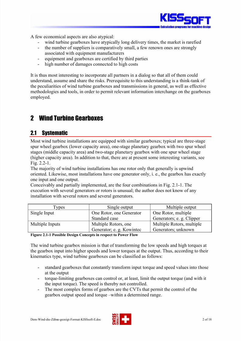
Types Single output Multiple output
Single Input One Rotor, one Generator
Standard case
One Rotor, multiple
Generators; e. g. Clipper
Multiple Inputs Multiple Rotors, one
Generator; e. g. Kowintec
Multiple Rotors, multiple
Generators; unknown
Figure 2.1-1 Possible Design Concepts in respect to Power Flow
The wind turbine gearbox mission is that of transforming the low speeds and high torques at
the gearbox input into higher speeds and lower torques at the output. Thus, according to their
kinematics type, wind turbine gearboxes can be classified as follows:
- standard gearboxes that constantly transform input torque and speed values into those
at the output
- torque-limiting gearboxes can control or, at least, limit the output torque (and with it
the input torque). The speed is thereby not controlled.
- The most complex forms of gearbox are the CVTs that permit the control of the
gearbox output speed and torque –within a determined range.
8/3/2019 Gearing Analysis for Wind Turbine
http://slidepdf.com/reader/full/gearing-analysis-for-wind-turbine 3/18
Dem-Wind-die-Zähne-gezeigt-Format-KISSsoft-E.doc 3 of 18
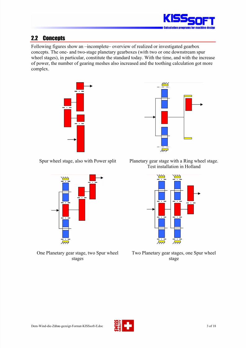
2.2 Concepts
Following figures show an –incomplete– overview of realized or investigated gearbox
concepts. The one- and two-stage planetary gearboxes (with two or one downstream spur
wheel stages), in particular, constitute the standard today. With the time, and with the increase
of power, the number of gearing meshes also increased and the toothing calculation got more
complex.
Spur wheel stage, also with Power split Planetary gear stage with a Ring wheel stage.
Test installation in Holland
One Planetary gear stage, two Spur wheel
stages
Two Planetary gear stages, one Spur wheel
stage
8/3/2019 Gearing Analysis for Wind Turbine
http://slidepdf.com/reader/full/gearing-analysis-for-wind-turbine 4/18
Dem-Wind-die-Zähne-gezeigt-Format-KISSsoft-E.doc 4 of 18
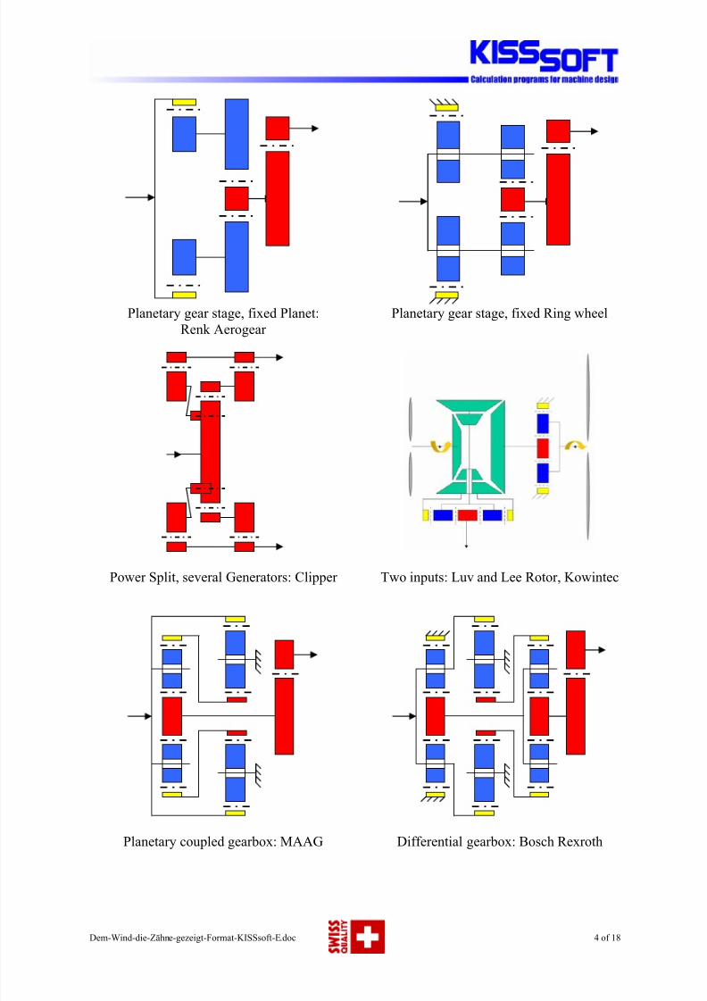
Planetary gear stage, fixed Planet:
Renk Aerogear
Planetary gear stage, fixed Ring wheel
Power Split, several Generators: Clipper Two inputs: Luv and Lee Rotor, Kowintec
Planetary coupled gearbox: MAAG Differential gearbox: Bosch Rexroth
8/3/2019 Gearing Analysis for Wind Turbine
http://slidepdf.com/reader/full/gearing-analysis-for-wind-turbine 5/18
Dem-Wind-die-Zähne-gezeigt-Format-KISSsoft-E.doc 5 of 18
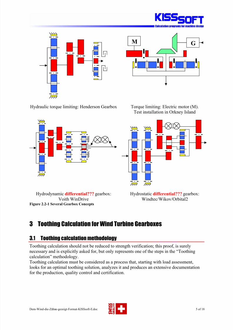
Hydraulic torque limiting: Henderson Gearbox Torque limiting: Electric motor (M).
Test installation in Orkney Island
Hydrodynamic differential??? gearbox:
Voith WinDrive
Hydrostatic differential??? gearbox:
Windtec/Wikov/Orbital2Figure 2.2-1 Several Gearbox Concepts
3 Toothing Calculation for Wind Turbine Gearboxes
3.1 Toothing calculation methodology
Toothing calculation should not be reduced to strength verification; this proof, is surely
necessary and is explicitly asked for, but only represents one of the steps in the “Toothing
calculation” methodology.
Toothing calculation must be considered as a process that, starting with load assessment,
looks for an optimal toothing solution, analyzes it and produces an extensive documentation
for the production, quality control and certification.
M G
8/3/2019 Gearing Analysis for Wind Turbine
http://slidepdf.com/reader/full/gearing-analysis-for-wind-turbine 6/18
Dem-Wind-die-Zähne-gezeigt-Format-KISSsoft-E.doc 6 of 18
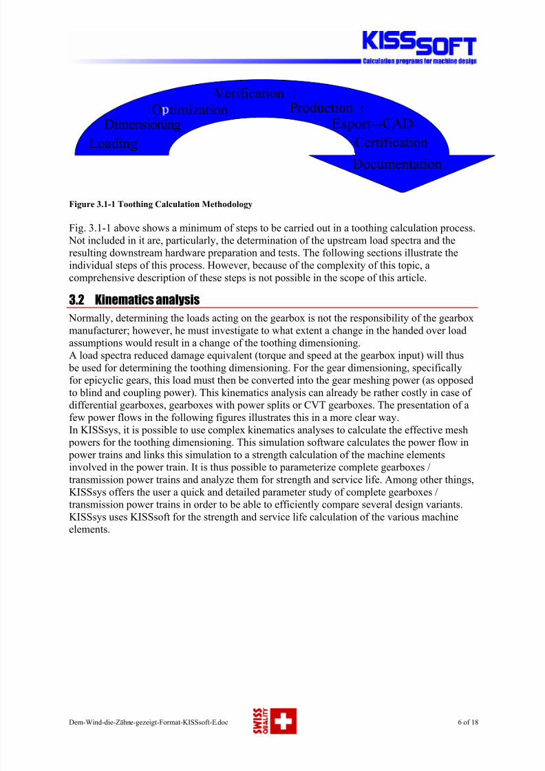
Figure 3.1-1 Toothing Calculation Methodology
Fig. 3.1-1 above shows a minimum of steps to be carried out in a toothing calculation process.
Not included in it are, particularly, the determination of the upstream load spectra and the
resulting downstream hardware preparation and tests. The following sections illustrate the
individual steps of this process. However, because of the complexity of this topic, acomprehensive description of these steps is not possible in the scope of this article.
3.2 Kinematics analysis
Normally, determining the loads acting on the gearbox is not the responsibility of the gearbox
manufacturer; however, he must investigate to what extent a change in the handed over load
assumptions would result in a change of the toothing dimensioning.
A load spectra reduced damage equivalent (torque and speed at the gearbox input) will thus
be used for determining the toothing dimensioning. For the gear dimensioning, specifically
for epicyclic gears, this load must then be converted into the gear meshing power (as opposed
to blind and coupling power). This kinematics analysis can already be rather costly in case of
differential gearboxes, gearboxes with power splits or CVT gearboxes. The presentation of afew power flows in the following figures illustrates this in a more clear way.
In KISSsys, it is possible to use complex kinematics analyses to calculate the effective mesh
powers for the toothing dimensioning. This simulation software calculates the power flow in
power trains and links this simulation to a strength calculation of the machine elements
involved in the power train. It is thus possible to parameterize complete gearboxes /
transmission power trains and analyze them for strength and service life. Among other things,
KISSsys offers the user a quick and detailed parameter study of complete gearboxes /
transmission power trains in order to be able to efficiently compare several design variants.
KISSsys uses KISSsoft for the strength and service life calculation of the various machine
elements.
Ex ort→CAD
Documentation
Dimensioni
Loading
O timizationVerification
Production
Certification
Auslegung
Optimierung Nachrechnung
HerstellungCAD Export
Dokumentation
ZertifizierungBelastung
Export→CAD
Documentation
Dimensioning
Loading
O timizationVerification
Production
Certification
8/3/2019 Gearing Analysis for Wind Turbine
http://slidepdf.com/reader/full/gearing-analysis-for-wind-turbine 7/18
Dem-Wind-die-Zähne-gezeigt-Format-KISSsoft-E.doc 7 of 18
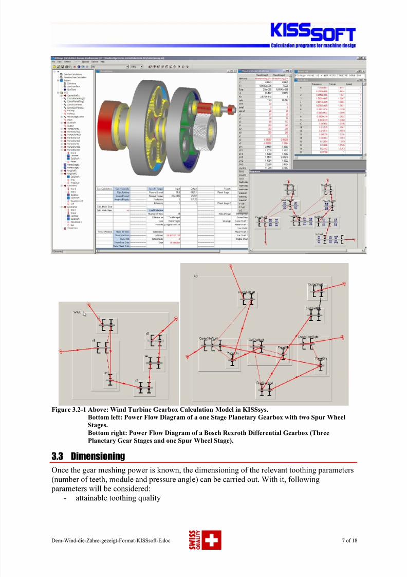
Figure 3.2-1 Above: Wind Turbine Gearbox Calculation Model in KISSsys.
Bottom left: Power Flow Diagram of a one Stage Planetary Gearbox with two Spur Wheel
Stages.
Bottom right: Power Flow Diagram of a Bosch Rexroth Differential Gearbox (Three
Planetary Gear Stages and one Spur Wheel Stage).
3.3 Dimensioning
Once the gear meshing power is known, the dimensioning of the relevant toothing parameters
(number of teeth, module and pressure angle) can be carried out. With it, following
parameters will be considered:
- attainable toothing quality
8/3/2019 Gearing Analysis for Wind Turbine
http://slidepdf.com/reader/full/gearing-analysis-for-wind-turbine 8/18
Dem-Wind-die-Zähne-gezeigt-Format-KISSsoft-E.doc 8 of 18
- material characteristics
- reference transmission ratio and acceptable deviation
- requested service life / safety
- installation conditions / mountability
It is especially important to consider here, the mountability conditions of the first planetarystage, because both the ring gear maximum possible diameter (manufacturing) and the
necessary planet wheel diameter (space for the planet bearings) restrict the manufacturer’s
liberty.
3.4 Toothing optimization
The toothing can afterwards be optimized, the variation of the following parameters being the
most usual:
- tooth depth (reaching an optimum transverse contact ratio)
- helix angle (reaching an optimum overlap ratio)
- addendum modification (influences specific slippage and strength)
- fillet optimization (e. g. bigger radius by tool module different than gear module)
- profile- and face modification (improving contact pattern, reducing meshing shock)
- surface treatment (hardening, smoothing)
Some selected points will be shortly described in the following sections.
3.4.1 Tooth depth optimization
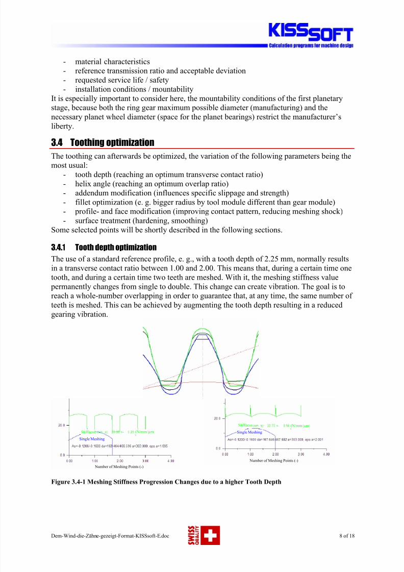
The use of a standard reference profile, e. g., with a tooth depth of 2.25 mm, normally results
in a transverse contact ratio between 1.00 and 2.00. This means that, during a certain time one
tooth, and during a certain time two teeth are meshed. With it, the meshing stiffness value
permanently changes from single to double. This change can create vibration. The goal is to
reach a whole-number overlapping in order to guarantee that, at any time, the same number of teeth is meshed. This can be achieved by augmenting the tooth depth resulting in a reduced
gearing vibration.
Figure 3.4-1 Meshing Stiffness Progression Changes due to a higher Tooth Depth
Single Meshing
Stiffness
Stiffness
(N/mm/µm
(N/mm/µm
Number of Meshing Points (-)
Number of Meshing Points (-)
Single Meshing
8/3/2019 Gearing Analysis for Wind Turbine
http://slidepdf.com/reader/full/gearing-analysis-for-wind-turbine 9/18
Dem-Wind-die-Zähne-gezeigt-Format-KISSsoft-E.doc 9 of 18
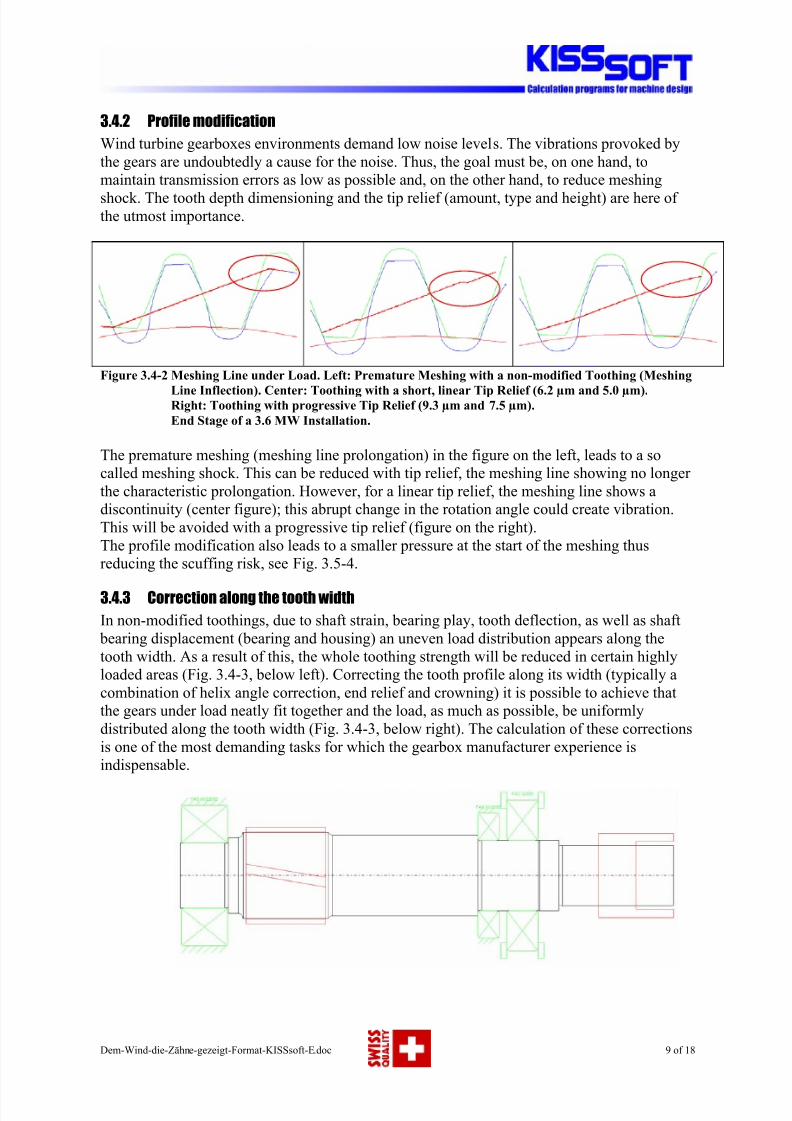
3.4.2 Profile modification
Wind turbine gearboxes environments demand low noise levels. The vibrations provoked by
the gears are undoubtedly a cause for the noise. Thus, the goal must be, on one hand, to
maintain transmission errors as low as possible and, on the other hand, to reduce meshing
shock. The tooth depth dimensioning and the tip relief (amount, type and height) are here of the utmost importance.
Figure 3.4-2 Meshing Line under Load. Left: Premature Meshing with a non-modified Toothing (Meshing
Line Inflection). Center: Toothing with a short, linear Tip Relief (6.2 µm and 5.0 µm).Right: Toothing with progressive Tip Relief (9.3 µm and 7.5 µm).
End Stage of a 3.6 MW Installation.
The premature meshing (meshing line prolongation) in the figure on the left, leads to a so
called meshing shock. This can be reduced with tip relief, the meshing line showing no longer
the characteristic prolongation. However, for a linear tip relief, the meshing line shows a
discontinuity (center figure); this abrupt change in the rotation angle could create vibration.
This will be avoided with a progressive tip relief (figure on the right).
The profile modification also leads to a smaller pressure at the start of the meshing thus
reducing the scuffing risk, see Fig. 3.5-4.
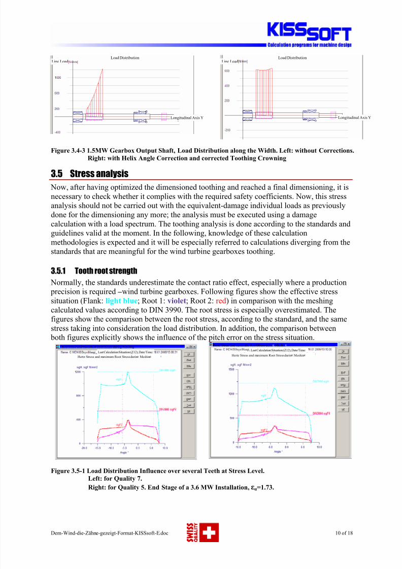
3.4.3 Correction along the tooth width
In non-modified toothings, due to shaft strain, bearing play, tooth deflection, as well as shaft
bearing displacement (bearing and housing) an uneven load distribution appears along the
tooth width. As a result of this, the whole toothing strength will be reduced in certain highly
loaded areas (Fig. 3.4-3, below left). Correcting the tooth profile along its width (typically a
combination of helix angle correction, end relief and crowning) it is possible to achieve that
the gears under load neatly fit together and the load, as much as possible, be uniformly
distributed along the tooth width (Fig. 3.4-3, below right). The calculation of these corrections
is one of the most demanding tasks for which the gearbox manufacturer experience is
indispensable.
8/3/2019 Gearing Analysis for Wind Turbine
http://slidepdf.com/reader/full/gearing-analysis-for-wind-turbine 10/18
Dem-Wind-die-Zähne-gezeigt-Format-KISSsoft-E.doc 10 of 18
Figure 3.4-3 1.5MW Gearbox Output Shaft, Load Distribution along the Width. Left: without Corrections.
Right: with Helix Angle Correction and corrected Toothing Crowning
3.5 Stress analysis
Now, after having optimized the dimensioned toothing and reached a final dimensioning, it is
necessary to check whether it complies with the required safety coefficients. Now, this stressanalysis should not be carried out with the equivalent-damage individual loads as previously
done for the dimensioning any more; the analysis must be executed using a damage
calculation with a load spectrum. The toothing analysis is done according to the standards and
guidelines valid at the moment. In the following, knowledge of these calculation
methodologies is expected and it will be especially referred to calculations diverging from the
standards that are meaningful for the wind turbine gearboxes toothing.
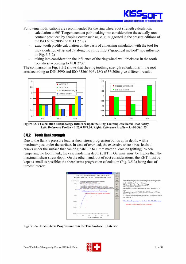
3.5.1 Tooth root strength
Normally, the standards underestimate the contact ratio effect, especially where a production
precision is required – wind turbine gearboxes. Following figures show the effective stress
situation (Flank: light blue; Root 1: violet; Root 2: red) in comparison with the meshing
calculated values according to DIN 3990. The root stress is especially overestimated. The
figures show the comparison between the root stress, according to the standard, and the same
stress taking into consideration the load distribution. In addition, the comparison between
both figures explicitly shows the influence of the pitch error on the stress situation.
Figure 3.5-1 Load Distribution Influence over several Teeth at Stress Level.
Left: for Quality 7.
Right: for Quality 5. End Stage of a 3.6 MW Installation, εα=1.73.
Load Distribution
Longitudinal Axis YLongitudinal Axis Y
Load DistributionLine Load Line Load
Load Distribution
Hertz Stress and maximum Root Stress durin Meshin
Hertz Stress and maximum Root Stress during Meshing
Last Calculation Situation (Z12), Date/Time:Hertz Stress and maximum Root Stress durin Meshin
Hertz Stress and maximum Root Stress durin Meshin
Last Calculation Situation (Z12), Date/Time:
8/3/2019 Gearing Analysis for Wind Turbine
http://slidepdf.com/reader/full/gearing-analysis-for-wind-turbine 11/18
Dem-Wind-die-Zähne-gezeigt-Format-KISSsoft-E.doc 11 of 18
Following modifications are recommended for the ring wheel root strength calculation:
- calculation at 60° Tangent contact point, taking into consideration the actually root
contour produced by shaping cutter such as, e. g., suggested in the present editions of
the ISO 6336:2006 (or VD I 2737)
- exact tooth profile calculation on the basis of a meshing simulation with the tool for the calculation of Y F and Y S along the entire fillet (“graphical method”, see influence
on Fig. 3.5-2)
- taking into consideration the influence of the ring wheel wall thickness in the tooth
root stress according to VDI 2737.
The comparison in Fig. 3.5-2 shows that the ring toothing strength calculations in the root
area according to DIN 3990 and ISO 6336:1996 / ISO 6336:2006 give different results.
Figure 3.5-2 Calculation Methodology Influence upon the Ring Toothing calculated Root Safety.
Left: Reference Profile = 1.25/0.38/1.00. Right: Reference Profile = 1.40/0.38/1.25.
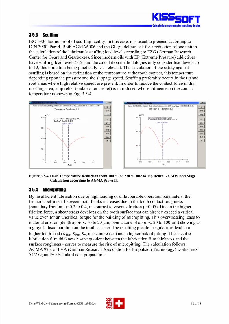
3.5.2 Tooth flank strength
Due to the flank’s pressure load, a shear stress progression builds up in depth, with a
maximum just under the surface. In case of overload, the excessive shear stress leads to
cracks under the surface that can originate 0.5 to 1 mm material erosion (pitting). When
tempering the tooth flank, the case hardening depth (EHT in German) must be higher than the
maximum shear stress depth. On the other hand, out of cost considerations, the EHT must be
kept as small as possible; the shear stress progression calculation (Fig. 3.5-3) being thus of
utmost interest.
Figure 3.5-3 Hertz Stress Progression from the Toot Surface → Interior.
0.8
0.85
0.9
0.95
1
1.05
1.1
1.15
YF3 YFS3 SF3
ISO6336 (erweitert) B Grafische MethodeGra hical Method
(extended)
0
0.5
1
1.5
2
2.5
3
YF3 YS3 SF3
ISO6336 C
ISO6336 B
ISO6336 (erweitert) B Gra hical Method
(extended)
Case Hardening Depth Pair 1 (Wheel 1 Material measured Value)
Name: Ex. 1 (Spur wheel), Date 15.01.2006/21:27:03
Hardening Depth Pair 1 (Wheel 1 Material measured Value)
Depth (my) Shear Stress Progression (determining the Hardening Depth)
(σH=1020.8 N/mm2
; ro_r= 19.3 mm)Maximum Shear Stress Depth (mm) 0.274EHT Suggestion : 0548 mm
(Suggestion acc. alternating Flexure Stress, Niemann : 0.922
mm)(Suggestion acc. AGMA 2101. Fig. 13: Normal 0.879 mm,Heavy 1.326 mm)
!! For production with grinding allowance, indicate the half on
the drawing) !!
Shear Stress Progression ( on the Basis of the Flank P ressure)
Material measured Value (from Database)
Vickers Hardness (HV)
8/3/2019 Gearing Analysis for Wind Turbine
http://slidepdf.com/reader/full/gearing-analysis-for-wind-turbine 12/18
Dem-Wind-die-Zähne-gezeigt-Format-KISSsoft-E.doc 12 of 18
3.5.3 Scuffing
ISO 6336 has no proof of scuffing facility; in this case, it is usual to proceed according to
DIN 3990, Part 4. Both AGMA6006 and the GL guidelines ask for a reduction of one unit in
the calculation of the lubricant’s scuffing load level according to FZG (German Research
Center for Gears and Gearboxes). Since modern oils with EP (Extreme Pressure) addictiveshave scuffing load levels >12, and the calculation methodologies only consider load levels up
to 12, this limitation being practically less relevant. The calculation of the safety against
scuffing is based on the estimation of the temperature at the tooth contact, this temperature
depending upon the pressure and the slippage speed. Scuffing preferably occurs in the tip and
root areas where high relative speeds are present. In order to reduce the contact force in this
meshing area, a tip relief (and/or a root relief) is introduced whose influence on the contact
temperature is shown in Fig. 3.5-4.
Figure 3.5-4 Flash Temperature Reduction from 300 °C to 230 °C due to Tip Relief. 3.6 MW End Stage.
Calculation according to AGMA 925-A03.
3.5.4 Micropitting
By insufficient lubrication due to high loading or unfavourable operation parameters, the
friction coefficient between tooth flanks increases due to the tooth contact roughness
(boundary friction, µ=0.2 to 0.4, in contrast to viscous friction µ=0.05). Due to the higher
friction force, a shear stress develops on the tooth surface that can already exceed a critical
value even for an uncritical torque for the building of micropitting. This overstressing leads to
material erosion (depth approx. 10 to 20 µm, over a zone of approx. 20 to 100 µm) showing as
a grayish discolouration on the tooth surface. The resulting profile irregularities lead to a
higher tooth load ( K Hα, K Fα, K ν, noise increases) and a higher risk of pitting. The specific
lubrication film thickness λ – the quotient between the lubrication film thickness and the
surface roughness – serves to measure the risk of micropitting. The calculation follows
AGMA 925, or FVA (German Research Association for Propulsion Technology) worksheets
54/259; an ISO Standard is in preparation.
Temperature at Tooth Contact (θB)
Date/Time:
Temperature at Tooth Contact [θ B ]
θ B
X Si
Helpθ B
Temperature at Tooth Contact [θ B ]
Maximum Contact Temperature 301.2Scuffing Probability 26.09 %
X Si
Temperature at Tooth Contact (θB)
Help
8/3/2019 Gearing Analysis for Wind Turbine
http://slidepdf.com/reader/full/gearing-analysis-for-wind-turbine 13/18
Dem-Wind-die-Zähne-gezeigt-Format-KISSsoft-E.doc 13 of 18
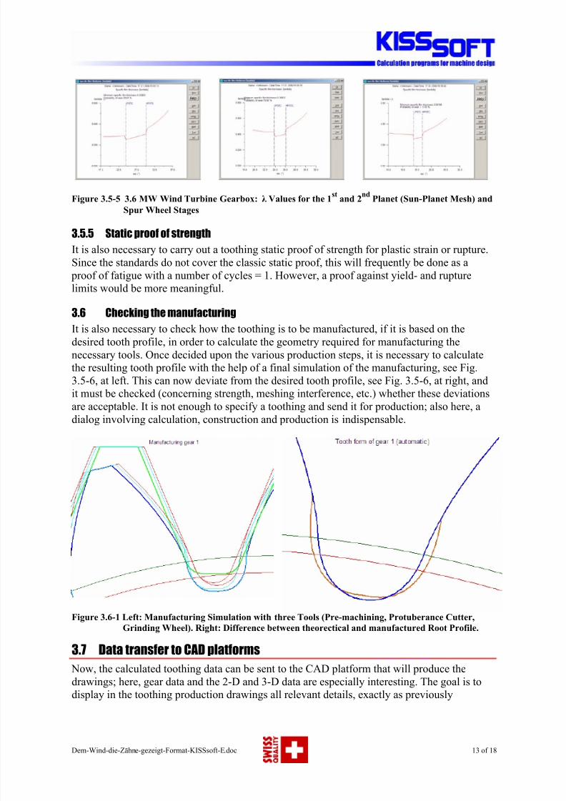
Figure 3.5-5 3.6 MW Wind Turbine Gearbox: λ Values for the 1st
and 2nd
Planet (Sun-Planet Mesh) and
Spur Wheel Stages
3.5.5 Static proof of strength
It is also necessary to carry out a toothing static proof of strength for plastic strain or rupture.
Since the standards do not cover the classic static proof, this will frequently be done as a
proof of fatigue with a number of cycles = 1. However, a proof against yield- and rupturelimits would be more meaningful.
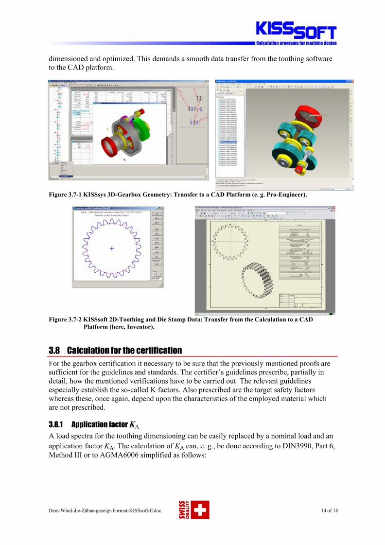
3.6 Checking the manufacturing
It is also necessary to check how the toothing is to be manufactured, if it is based on the
desired tooth profile, in order to calculate the geometry required for manufacturing the
necessary tools. Once decided upon the various production steps, it is necessary to calculate
the resulting tooth profile with the help of a final simulation of the manufacturing, see Fig.
3.5-6, at left. This can now deviate from the desired tooth profile, see Fig. 3.5-6, at right, and
it must be checked (concerning strength, meshing interference, etc.) whether these deviations
are acceptable. It is not enough to specify a toothing and send it for production; also here, a
dialog involving calculation, construction and production is indispensable.
Figure 3.6-1 Left: Manufacturing Simulation with three Tools (Pre-machining, Protuberance Cutter,
Grinding Wheel). Right: Difference between theorectical and manufactured Root Profile.
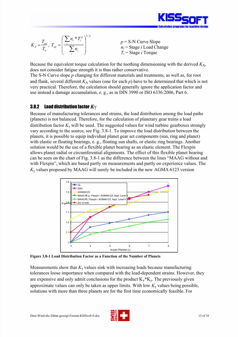
3.7 Data transfer to CAD platforms
Now, the calculated toothing data can be sent to the CAD platform that will produce the
drawings; here, gear data and the 2-D and 3-D data are especially interesting. The goal is to
display in the toothing production drawings all relevant details, exactly as previously
HelpHelp Help
8/3/2019 Gearing Analysis for Wind Turbine
http://slidepdf.com/reader/full/gearing-analysis-for-wind-turbine 14/18
Dem-Wind-die-Zähne-gezeigt-Format-KISSsoft-E.doc 14 of 18
dimensioned and optimized. This demands a smooth data transfer from the toothing software
to the CAD platform.
Figure 3.7-1 KISSsys 3D-Gearbox Geometry: Transfer to a CAD Platform (e. g. Pro-Engineer).
Figure 3.7-2 KISSsoft 2D-Toothing and Die Stamp Data: Transfer from the Calculation to a CAD
Platform (here, Inventor).
3.8 Calculation for the certification
For the gearbox certification it necessary to be sure that the previously mentioned proofs are
sufficient for the guidelines and standards. The certifier’s guidelines prescribe, partially in
detail, how the mentioned verifications have to be carried out. The relevant guidelinesespecially establish the so-called K factors. Also prescribed are the target safety factors
whereas these, once again, depend upon the characteristics of the employed material which
are not prescribed.
3.8.1 Application factor K A
A load spectra for the toothing dimensioning can be easily replaced by a nominal load and an
application factor K A. The calculation of K A can, e. g., be done according to DIN3990, Part 6,
Method III or to AGMA6006 simplified as follows:
8/3/2019 Gearing Analysis for Wind Turbine
http://slidepdf.com/reader/full/gearing-analysis-for-wind-turbine 15/18
Dem-Wind-die-Zähne-gezeigt-Format-KISSsoft-E.doc 15 of 18
n
eq
AT
T K = ,
p
i
i
i
p
ii
eqn
T n
T
/1
*
=
∑∑
p = S-N Curve Slope
ni = Stage i Load Change
T i = Stage i Torque
Because the equivalent torque calculation for the toothing dimensioning with the derived K A,
does not consider fatigue strength it is thus rather conservative.
The S-N Curve slope p changing for different materials and treatments, as well as, for root
and flank, several different K A values (one for each p) have to be determined that which is not
very practical. Therefore, the calculation should generally ignore the application factor and
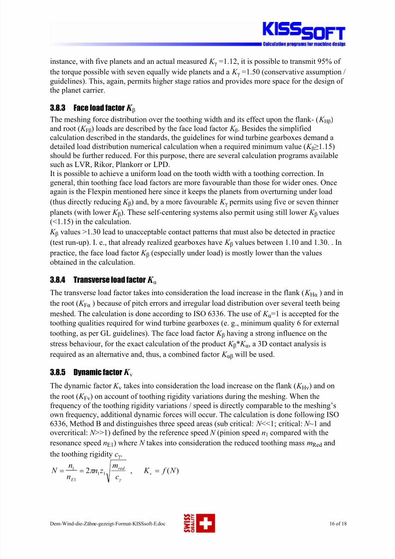
use instead a damage accumulation, e. g., as in DIN 3990 or ISO 6336:2006, Part 6.3.8.2 Load distribution factor K γ
Because of manufacturing tolerances and strains, the load distribution among the load paths
(planets) is not balanced. Therefore, for the calculation of planetary gear trains a load
distribution factor K γ will be used. The suggested values for wind turbine gearboxes strongly
vary according to the source, see Fig. 3.8-1. To improve the load distribution between the
planets, it is possible to equip individual planet gear set components (sun, ring and planet)
with elastic or floating bearings, e. g., floating sun shafts, or elastic ring bearings. Another
solution would be the use of a flexible planet bearing as an elastic element. The Flexpin
allows planet radial or circumferential alignments. The effect of this flexible planet bearing
can be seen on the chart of Fig. 3.8-1 as the difference between the lines “MAAG without and
with Flexpin”, which are based partly on measurements and partly on experience values. The
K γ values proposed by MAAG will surely be included in the new AGMA 6123 version
Figure 3.8-1 Load Distribution Factor as a Function of the Number of Planets
Measurements show that K γ values sink with increasing loads because manufacturing
tolerances loose importance when compared with the load-dependent strains. However, they
are expensive and only admit conclusions for the product K v*K γ. The previously given
approximate values can only be taken as upper limits. With low K γ values being possible,
solutions with more than three planets are for the first time economically feasible. For
1
1.1
1.2
1.3
1.4
1.5
1.6
3 4 5 6 7 8
Anzahl Planeten [-]
K gamma [-]
GL
DNV
AGMA6123
MAAG ohne Flexpin / AGMA6123, Appl. Level 3
MAAG mit Flexpin / AGMA6123, Appl. Level 4
IEC 61400
/
/o
8/3/2019 Gearing Analysis for Wind Turbine
http://slidepdf.com/reader/full/gearing-analysis-for-wind-turbine 16/18
Dem-Wind-die-Zähne-gezeigt-Format-KISSsoft-E.doc 16 of 18
instance, with five planets and an actual measured K γ =1.12, it is possible to transmit 95% of
the torque possible with seven equally wide planets and a K γ =1.50 (conservative assumption /
guidelines). This, again, permits higher stage ratios and provides more space for the design of
the planet carrier.
3.8.3 Face load factor K β
The meshing force distribution over the toothing width and its effect upon the flank- ( K Hβ)
and root ( K Fβ) loads are described by the face load factor K β. Besides the simplified
calculation described in the standards, the guidelines for wind turbine gearboxes demand a
detailed load distribution numerical calculation when a required minimum value ( K β≥1.15)
should be further reduced. For this purpose, there are several calculation programs available
such as LVR, Rikor, Plankorr or LPD.
It is possible to achieve a uniform load on the tooth width with a toothing correction. In
general, thin toothing face load factors are more favourable than those for wider ones. Once
again is the Flexpin mentioned here since it keeps the planets from overturning under load(thus directly reducing K β) and, by a more favourable K γ permits using five or seven thinner
planets (with lower K β). These self-centering systems also permit using still lower K β values
(<1.15) in the calculation.
K β values >1.30 lead to unacceptable contact patterns that must also be detected in practice
(test run-up). I. e., that already realized gearboxes have K β values between 1.10 and 1.30. . In
practice, the face load factor K β (especially under load) is mostly lower than the values
obtained in the calculation.
3.8.4 Transverse load factor K α
The transverse load factor takes into consideration the load increase in the flank ( K Hα ) and in
the root ( K Fα ) because of pitch errors and irregular load distribution over several teeth being
meshed. The calculation is done according to ISO 6336. The use of K α=1 is accepted for the
toothing qualities required for wind turbine gearboxes (e. g., minimum quality 6 for external
toothing, as per GL guidelines). The face load factor K β having a strong influence on the
stress behaviour, for the exact calculation of the product K β* K α, a 3D contact analysis is
required as an alternative and, thus, a combined factor K αβ will be used.
3.8.5 Dynamic factor K v
The dynamic factor K ν takes into consideration the load increase on the flank ( K Hν) and onthe root ( K Fv) on account of toothing rigidity variations during the meshing. When the
frequency of the toothing rigidity variations / speed is directly comparable to the meshing’s
own frequency, additional dynamic forces will occur. The calculation is done following ISO
6336, Method B and distinguishes three speed areas (sub critical: N <<1; critical: N ~1 and
overcritical: N >>1) defined by the reference speed N (pinion speed n1 compared with the
resonance speed nE1) where N takes into consideration the reduced toothing mass mRed and
the toothing rigidity cγ.
γ
π c
m z n
n
n N red
E
11
1
1 2== , )( N f K v =
8/3/2019 Gearing Analysis for Wind Turbine
http://slidepdf.com/reader/full/gearing-analysis-for-wind-turbine 17/18
Dem-Wind-die-Zähne-gezeigt-Format-KISSsoft-E.doc 17 of 18
Because of the low speed, wind turbine gearboxes will be operated in the sub critical area and
the K ν values will be accordingly set. The certification directives for wind turbine gearboxes,
as well as the relevant standards estipulate a K ν ≥ 1.05 value. Should a lower value be used, a
measurement or more detailed calculation must be carried out.
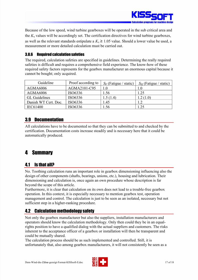
3.8.6 Required calculation safeties
The required, calculation safeties are specified in guidelines. Determining the really required
safeties is difficult and requires a comprehensive field experience. The know-how of these
required safety factors represents for the gearbox manufacturer an enormous capital because it
cannot be bought; only acquired.
Guideline Proof according to S F (Fatigue / static) S H (Fatigue / static)
AGMA6006 AGMA2101-C95 1.0 1.0
AGMA6006 ISO6336 1.56 1.25
GL Guidelines ISO6336 1.5 (1.4) 1.2 (1.0)Danish WT Cert. Doc. ISO6336 1.45 1.2
IEC61400 ISO6336 1.56 1.25
3.9 Documentation
All calculations have to be documented so that they can be submitted to and checked by the
certification. Documentation costs increase steadily and is necessary here that it could be
automatically produced.
4 Summary
4.1 Is that all?
No. Toothing calculation runs an important role in gearbox dimensioning influencing also the
design of other components (shafts, bearings, unions, etc.), housing and lubrication. Their
dimensioning and calculation is, once again an own procedure whose description is far
beyond the scope of this article.
Furthermore, it is clear that calculation on its own does not lead to a trouble-free gearbox
operation. In this context, it is especially necessary to mention gearbox test, operationmanagement and control. The calculation is just to be seen as an isolated, necessary but not
sufficient step in a higher-ranking procedure.
4.2 Calculation methodology safety
Not only the gearbox manufacturer but also the suppliers, installation manufacturers and
operators should know the calculation methodology. Only then could they be in an equal-
rights position to have a qualified dialog with the actual suppliers and customers. The risks
inherent to the acceptance officer of a gearbox or installation will then be transparent and
could be mutually shared.
The calculation process should be as such implemented and controlled. Still, it is
unfortunately that, also among gearbox manufacturers, it will not consistently be seen as a
8/3/2019 Gearing Analysis for Wind Turbine
http://slidepdf.com/reader/full/gearing-analysis-for-wind-turbine 18/18
process which must work in all departments in a self-evident way. Past are the days in which
the calculation department calculates something, then the manufacturer builds something else
and in the end, the production produces something different. To avoid this, we need tools that
could be employed during the entire process. These tools must also be in a position to convey
information in a safe way from component suppliers (e. g., gear manufactures) to gearboxmanufacturers and then, via equipment manufacturers, to the end customers (the operators).
The latter would thus be able to take care of maintenance and repairs under their own
responsibility because all the relevant information will be available, even when the
maintenance contract with the equipment manufacturer has expired.
4.3 What next?
In gearbox manufacturing, the calculation must be conceived as a process which also involves
manufacturing and production. By many gearbox manufacturers it is not yet introduced the
need for all departments to intensively intercommunicate, being still strongly obstinate in
pursuing the department-thinking mentality with the result of losing much information and
energy at the many interfaces. .
In the wind energy area, the calculation conception must also include, in addition to the
gearbox manufacturer, the load team, the equipment manufacturer, certification officers and
the end customer. Besides this, it is necessary some effort on part of the equipment
manufacturer and, especially, the operator, in order to be able to collaborate in this process.
The dialog with the gearbox manufacturer requires a considerably amount of knowledge
which the certification officers must possess, by the equipment manufacturers strongly
disappears and, by the operator rarely exists.
This ought to be changed!
5 Bibliography
U. Giger, G.P. Fox, Leistungsverzweigte Planetengetriebe in Windenergieanlagen mit
flexibler Planetenlagerung, ATK03
R. Grzybowski, B. Niederstucke, Betriebsfestigkeitsberechnung von Getrieben in
Windenergieanlagen mit Verweildauerkollektiven, Allianz Report 2004
R. Poore, T. Lettenmaier, Alternative Design Study Report: Wind PACT Advanced Wind
Turbine Drive Train Designs Study, NREL/SR-500-33196
H. Dinner, Gleichberechtigter Dialog als Erfolgsrezept, Verzahnungsberechnung für Windenergieanlagengetriebe, Antriebstechnik 5/2006
F. D. Krull, T. Siegenbruck, Windenergieanlagen fordern hohe Leistungsdichten, Ermittlung
der Breitenlastverteilung in Planetengetrieben, Antriebstechnik 9/2004
H. Dinner, Integrated Dimensioning, Optimization, Verification and producing Drawings for
Wind turbine gearboxes, Planet Trains, Haus der Technik, März 07